GAPS Guidelines GAP.17.4.0 A Publication of Global Asset Protection Services LLC STEEL INDUSTRY ABSTRACT INTRODUCTION The reduction of iron ore to make ferrous metals is believed to have begun sometime around 2000 B.C. According to archaeological evidence, these metals were first used for tools, weapons and jewelry. The earliest reduction process was probably nothing more than embedding ore in burning charcoal and collecting the molten metal. Since then, many process refinements have been made that enable accurate control of the metallurgical properties of today’s steels. Raw materials for the production of steel include iron ore, limestone, coal, alloy metals and oxygen. Processing is done in four major steps: mining, reduction, refining and fabrication. Mining is usually done separately while the other operations are usually incorporated into one facility. Finished products include structural shapes, bars, rod, wire, pipe, plate and sheet (strip). Figure 1 shows a simplified flow chart and Figure 2 a process flow diagram for manufacturing steel products. More detailed information may be found in Making, Shaping and Treating of Steel, an AISE publication. The large loss potentials in the steel industry are those associated with the furnaces and rolling mills. Blast furnaces, steel-making furnaces and reheat furnaces present molten metal spill hazards, and some of them also present the hazards associated with fuel firing. Rolling mills include the hazards of combustible cooling, hydraulic and rolling fluids and additional loss exposures from large motors and gear drives. Most equipment in the steel industry is very expensive and can take a long time to replace. Furthermore, environmental regulations often require older equipment to be upgraded. For these reasons, both the property and business interruption portions of a loss can be very large. It is therefore important that a steel processing facility install proper protection for all hazards and implement excellent loss prevention programs. PROCESSES AND HAZARDS Mining Iron ore is collected by open pit mining when the ore is near the surface, but is sometimes collected by vertical shaft mining. Mining involves large, specialized mobile equipment such as drills, power shovels, drag lines, loaders and hauling vehicles. It also involves equipment such as conveyors, crushers, stackers, reclaimers and buildings for maintenance and storage. Mining operations usually include water treatment facilities. Larger mining operations may also have their own power generation equipment. In open pit mining, drills make holes for the charges that blast open the mining pit. Shovels and drag lines move the loosened rock, and loaders put it onto vehicles or conveyors. Underground mining also requires costly equipment for digging shafts and tunnels, hauling ore from the mine and keeping the mine dry. Before ore leaves the mining area, it is usually crushed, washed, screened, stacked and blended with a special blending rake. Such preparation of ore is called beneficiation. 100 Constitution Plaza, Hartford, Connecticut 06103 Copyright 2015, Global Asset Protection Services LLC Global Asset Protection Services LLC and its affiliated organizations provide loss prevention surveys and other risk management, business continuity and facility asset management services. Unless otherwise stated in writing, our personnel, publications, services, and surveys do not address life safety or third party liability issues. The provision of any service is not meant to imply that every possible hazard has been identified at a facility or that no other hazards exist. Global Asset Protection Services LLC and its affiliated organizations do not assume, and shall have no liability for the control, correction, continuation or modification of any existing conditions or operations. We specifically disclaim any warranty or representation that compliance with any advice or recommendation in any document or other communication will make a facility or operation safe or healthful, or put it in compliance with any law, rule or regulation. If there are any questions concerning any recommendations, or if you have alternative solutions, please contact us.

Welcome message from author
This document is posted to help you gain knowledge. Please leave a comment to let me know what you think about it! Share it to your friends and learn new things together.
Transcript
GAPS Guidelines GAP.17.4.0
A Publication of Global Asset Protection Services LLC
STEEL INDUSTRY ABSTRACT
INTRODUCTION The reduction of iron ore to make ferrous metals is believed to have begun sometime around 2000 B.C. According to archaeological evidence, these metals were first used for tools, weapons and jewelry. The earliest reduction process was probably nothing more than embedding ore in burning charcoal and collecting the molten metal. Since then, many process refinements have been made that enable accurate control of the metallurgical properties of today’s steels.
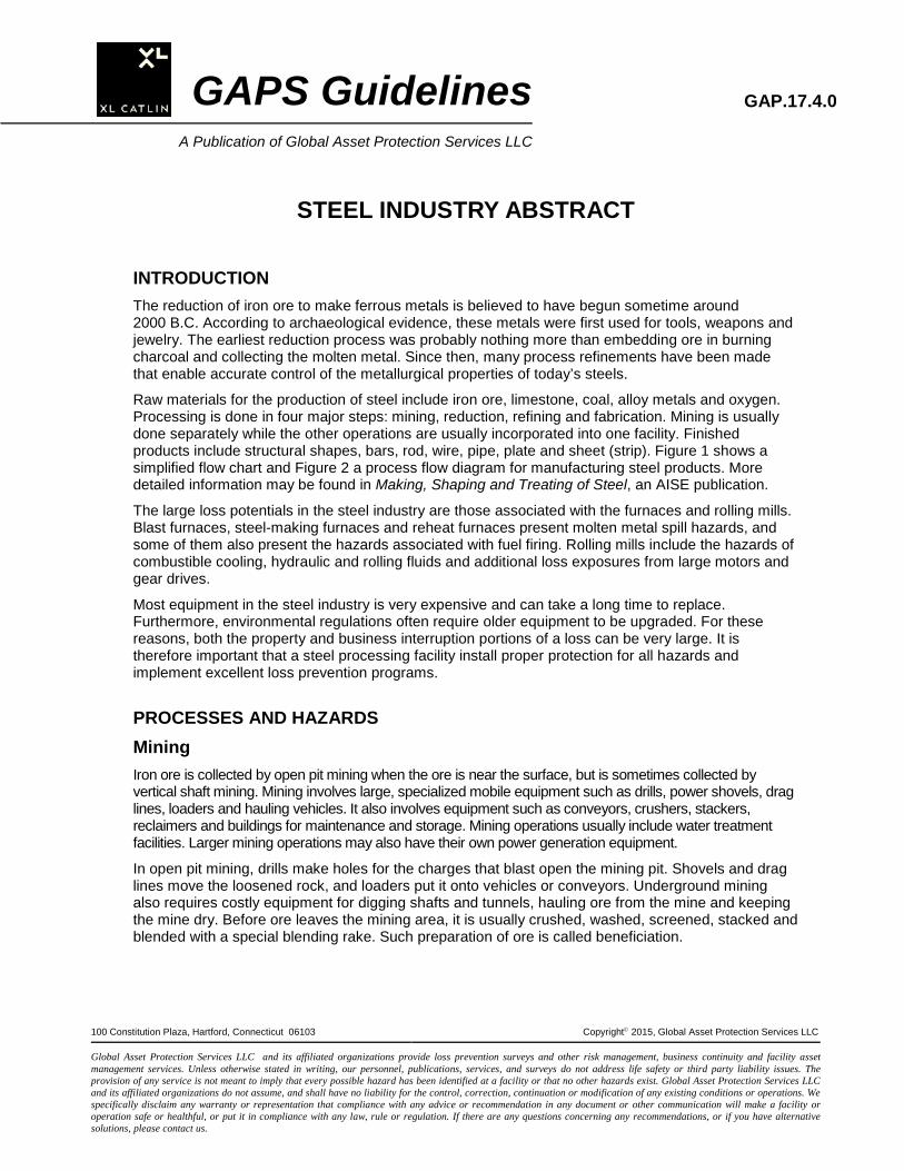
Raw materials for the production of steel include iron ore, limestone, coal, alloy metals and oxygen. Processing is done in four major steps: mining, reduction, refining and fabrication. Mining is usually done separately while the other operations are usually incorporated into one facility. Finished products include structural shapes, bars, rod, wire, pipe, plate and sheet (strip). Figure 1 shows a simplified flow chart and Figure 2 a process flow diagram for manufacturing steel products. More detailed information may be found in Making, Shaping and Treating of Steel, an AISE publication.
The large loss potentials in the steel industry are those associated with the furnaces and rolling mills. Blast furnaces, steel-making furnaces and reheat furnaces present molten metal spill hazards, and some of them also present the hazards associated with fuel firing. Rolling mills include the hazards of combustible cooling, hydraulic and rolling fluids and additional loss exposures from large motors and gear drives.
Most equipment in the steel industry is very expensive and can take a long time to replace. Furthermore, environmental regulations often require older equipment to be upgraded. For these reasons, both the property and business interruption portions of a loss can be very large. It is therefore important that a steel processing facility install proper protection for all hazards and implement excellent loss prevention programs.
PROCESSES AND HAZARDS Mining Iron ore is collected by open pit mining when the ore is near the surface, but is sometimes collected by vertical shaft mining. Mining involves large, specialized mobile equipment such as drills, power shovels, drag lines, loaders and hauling vehicles. It also involves equipment such as conveyors, crushers, stackers, reclaimers and buildings for maintenance and storage. Mining operations usually include water treatment facilities. Larger mining operations may also have their own power generation equipment.
In open pit mining, drills make holes for the charges that blast open the mining pit. Shovels and drag lines move the loosened rock, and loaders put it onto vehicles or conveyors. Underground mining also requires costly equipment for digging shafts and tunnels, hauling ore from the mine and keeping the mine dry. Before ore leaves the mining area, it is usually crushed, washed, screened, stacked and blended with a special blending rake. Such preparation of ore is called beneficiation.
100 Constitution Plaza, Hartford, Connecticut 06103 Copyright 2015, Global Asset Protection Services LLC
Global Asset Protection Services LLC and its affiliated organizations provide loss prevention surveys and other risk management, business continuity and facility asset management services. Unless otherwise stated in writing, our personnel, publications, services, and surveys do not address life safety or third party liability issues. The provision of any service is not meant to imply that every possible hazard has been identified at a facility or that no other hazards exist. Global Asset Protection Services LLC and its affiliated organizations do not assume, and shall have no liability for the control, correction, continuation or modification of any existing conditions or operations. We specifically disclaim any warranty or representation that compliance with any advice or recommendation in any document or other communication will make a facility or operation safe or healthful, or put it in compliance with any law, rule or regulation. If there are any questions concerning any recommendations, or if you have alternative solutions, please contact us.
GAP.17.4.0
Figure 1. Simplified Flow Chart For Manufacturing Steel Products.
GAPS Guidelines 2 A Publication of Global Asset Protection Services LLC
GAP.17.4.0
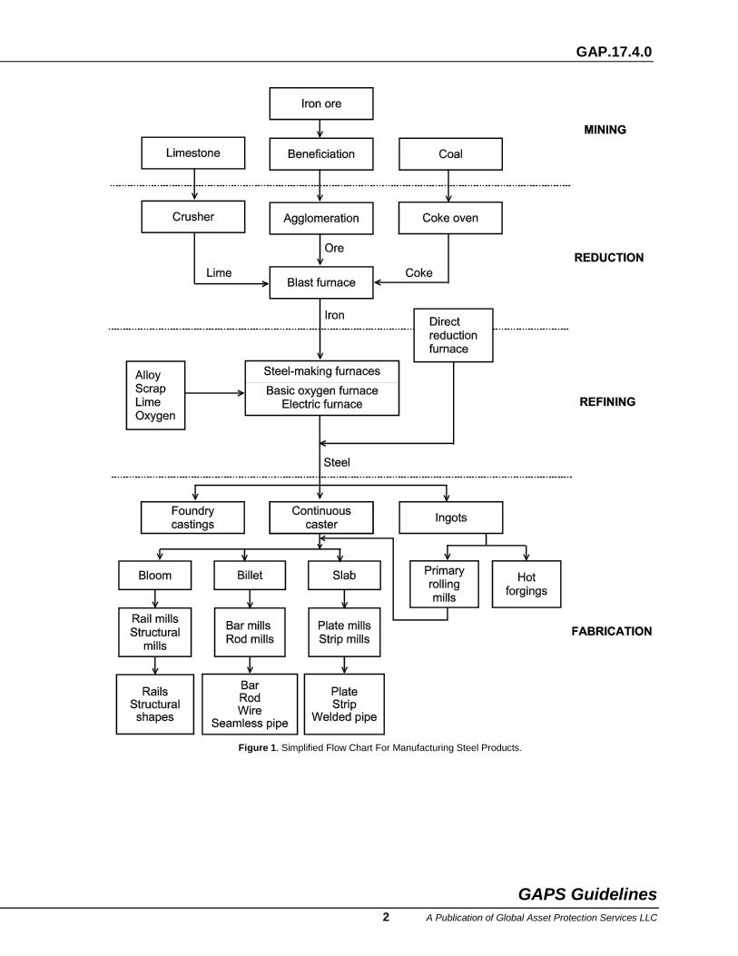
Figure 2. Process Flow Diagram For Manufacturing Steel Products.
Loss exposure in mining operations includes machinery breakdown and fire in mobile equipment. Hydraulic oil and diesel fuel fires are common, as is electrical breakdown in motors. Conveyor belt fires can destroy conveyor structural supports. Conveyor or crusher breakdown can result in long downtime and disrupt material flow to the processing facility’s blast furnace.
Reduction (Iron Making)
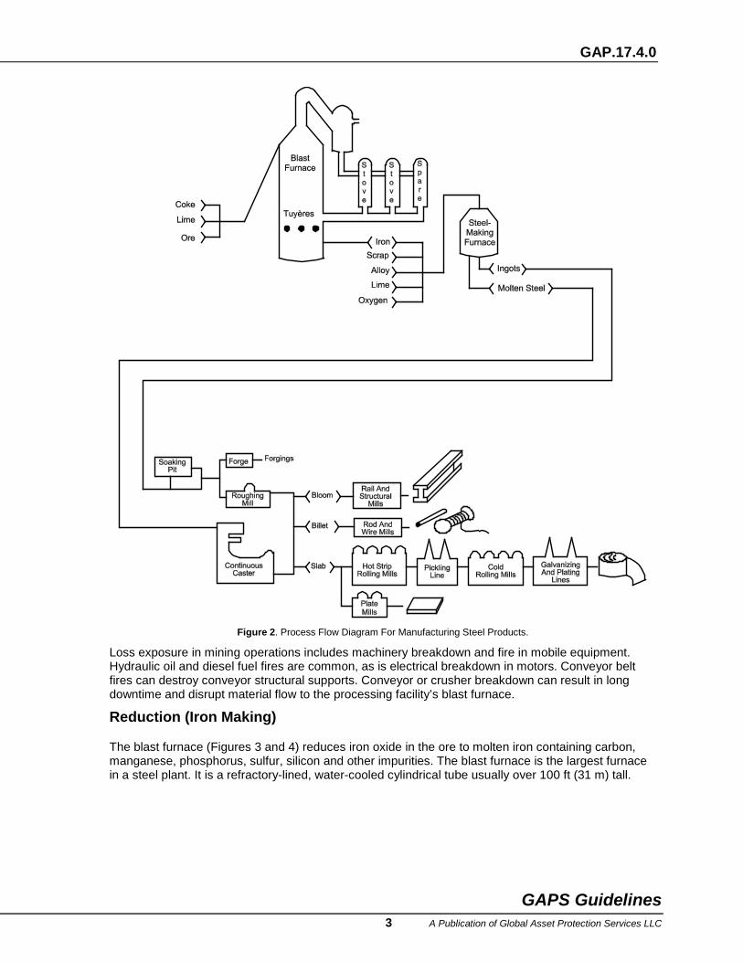
The blast furnace (Figures 3 and 4) reduces iron oxide in the ore to molten iron containing carbon, manganese, phosphorus, sulfur, silicon and other impurities. The blast furnace is the largest furnace in a steel plant. It is a refractory-lined, water-cooled cylindrical tube usually over 100 ft (31 m) tall.
GAPS Guidelines 3 A Publication of Global Asset Protection Services LLC
GAP.17.4.0
Figure 3. Blast Furnace.
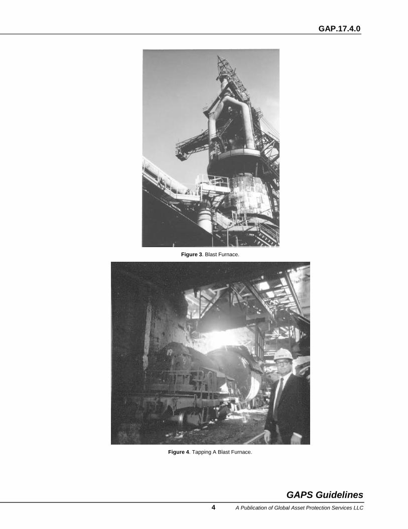
Figure 4. Tapping A Blast Furnace.
GAPS Guidelines 4 A Publication of Global Asset Protection Services LLC
GAP.17.4.0
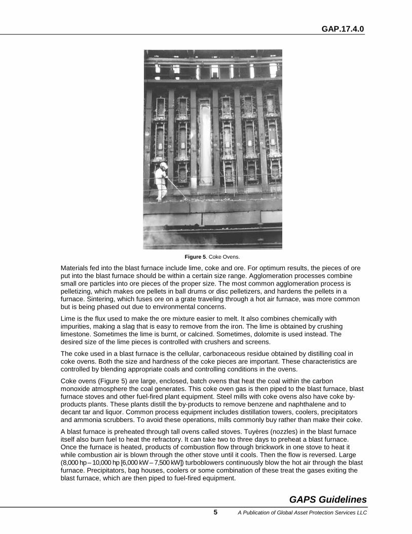
Figure 5. Coke Ovens.
Materials fed into the blast furnace include lime, coke and ore. For optimum results, the pieces of ore put into the blast furnace should be within a certain size range. Agglomeration processes combine small ore particles into ore pieces of the proper size. The most common agglomeration process is pelletizing, which makes ore pellets in ball drums or disc pelletizers, and hardens the pellets in a furnace. Sintering, which fuses ore on a grate traveling through a hot air furnace, was more common but is being phased out due to environmental concerns.
Lime is the flux used to make the ore mixture easier to melt. It also combines chemically with impurities, making a slag that is easy to remove from the iron. The lime is obtained by crushing limestone. Sometimes the lime is burnt, or calcined. Sometimes, dolomite is used instead. The desired size of the lime pieces is controlled with crushers and screens.
The coke used in a blast furnace is the cellular, carbonaceous residue obtained by distilling coal in coke ovens. Both the size and hardness of the coke pieces are important. These characteristics are controlled by blending appropriate coals and controlling conditions in the ovens.
Coke ovens (Figure 5) are large, enclosed, batch ovens that heat the coal within the carbon monoxide atmosphere the coal generates. This coke oven gas is then piped to the blast furnace, blast furnace stoves and other fuel-fired plant equipment. Steel mills with coke ovens also have coke by-products plants. These plants distill the by-products to remove benzene and naphthalene and to decant tar and liquor. Common process equipment includes distillation towers, coolers, precipitators and ammonia scrubbers. To avoid these operations, mills commonly buy rather than make their coke.
A blast furnace is preheated through tall ovens called stoves. Tuyères (nozzles) in the blast furnace itself also burn fuel to heat the refractory. It can take two to three days to preheat a blast furnace. Once the furnace is heated, products of combustion flow through brickwork in one stove to heat it while combustion air is blown through the other stove until it cools. Then the flow is reversed. Large (8,000 hp – 10,000 hp [6,000 kW – 7,500 kW]) turboblowers continuously blow the hot air through the blast furnace. Precipitators, bag houses, coolers or some combination of these treat the gases exiting the blast furnace, which are then piped to fuel-fired equipment.
GAPS Guidelines 5 A Publication of Global Asset Protection Services LLC
GAP.17.4.0
Loss exposures from the blast furnace include molten metal breakout, cooling water leaks and steam explosions, turboblower breakdown and combustion explosions involving the carbon monoxide rich blast furnace gas. The blast furnace is run continuously between refractory relinings, so there is no chance to inspect or repair it at any other time. Pollution control equipment used with the blast furnace also presents a fire loss potential.
Refining (Steel Making) Steel-making furnaces refine molten iron into steel by removing carbon and adding oxygen, lime, scrap and alloys. The amount and types of additives, furnace temperature, and length of the oxygen blow all affect the characteristics of the steel.
Some steel recipes call for additional materials. For example, calcium carbide is added to remove sulfur from some steels. This additive is a concern because it forms acetylene when exposed to water. To make stainless steel, argon is mixed with the oxygen used to blow the furnace. This achieves higher carbon removal. Depending on the type and grade of steel being made, other additives such as nickel, chrome, manganese, molybdenum, and silicon may also be used.
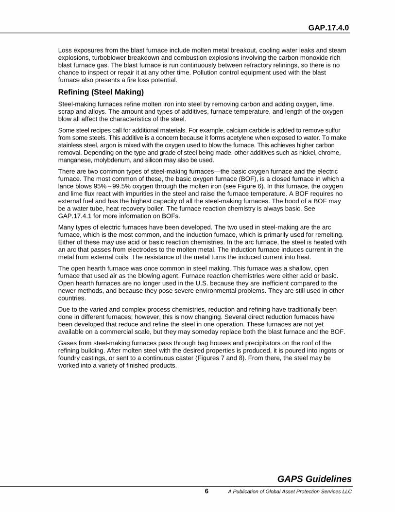
There are two common types of steel-making furnaces—the basic oxygen furnace and the electric furnace. The most common of these, the basic oxygen furnace (BOF), is a closed furnace in which a lance blows 95% – 99.5% oxygen through the molten iron (see Figure 6). In this furnace, the oxygen and lime flux react with impurities in the steel and raise the furnace temperature. A BOF requires no external fuel and has the highest capacity of all the steel-making furnaces. The hood of a BOF may be a water tube, heat recovery boiler. The furnace reaction chemistry is always basic. See GAP.17.4.1 for more information on BOFs.
Many types of electric furnaces have been developed. The two used in steel-making are the arc furnace, which is the most common, and the induction furnace, which is primarily used for remelting. Either of these may use acid or basic reaction chemistries. In the arc furnace, the steel is heated with an arc that passes from electrodes to the molten metal. The induction furnace induces current in the metal from external coils. The resistance of the metal turns the induced current into heat.
The open hearth furnace was once common in steel making. This furnace was a shallow, open furnace that used air as the blowing agent. Furnace reaction chemistries were either acid or basic. Open hearth furnaces are no longer used in the U.S. because they are inefficient compared to the newer methods, and because they pose severe environmental problems. They are still used in other countries.
Due to the varied and complex process chemistries, reduction and refining have traditionally been done in different furnaces; however, this is now changing. Several direct reduction furnaces have been developed that reduce and refine the steel in one operation. These furnaces are not yet available on a commercial scale, but they may someday replace both the blast furnace and the BOF.
Gases from steel-making furnaces pass through bag houses and precipitators on the roof of the refining building. After molten steel with the desired properties is produced, it is poured into ingots or foundry castings, or sent to a continuous caster (Figures 7 and 8). From there, the steel may be worked into a variety of finished products.
GAPS Guidelines 6 A Publication of Global Asset Protection Services LLC
GAP.17.4.0
Figure 6. Pouring From A Basic Oxygen Furnace.
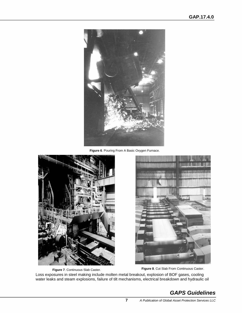
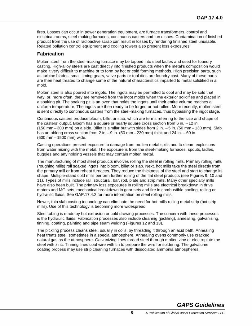
Figure 7. Continuous Slab Caster.
Figure 8. Cut Slab From Continuous Caster.
Loss exposures in steel making include molten metal breakout, explosion of BOF gases, cooling water leaks and steam explosions, failure of tilt mechanisms, electrical breakdown and hydraulic oil
GAPS Guidelines 7 A Publication of Global Asset Protection Services LLC
GAP.17.4.0
fires. Losses can occur in power generation equipment, arc furnace transformers, control and electrical rooms, steel-making furnaces, continuous casters and tun dishes. Contamination of finished product from the use of radioactive scrap can result in losses by rendering finished steel unusable. Related pollution control equipment and cooling towers also present loss exposures.
Fabrication Molten steel from the steel-making furnace may be tapped into steel ladles and used for foundry casting. High-alloy steels are cast directly into finished products when the metal’s composition would make it very difficult to machine or to form by hot or cold forming methods. High precision parts, such as turbine blades, small timing gears, valve parts or tool dies are foundry cast. Many of these parts are then heat treated to change some of the natural characteristics imparted to metal solidified in a mold.
Molten steel is also poured into ingots. The ingots may be permitted to cool and may be sold that way, or, more often, they are removed from the ingot molds when the exterior solidifies and placed in a soaking pit. The soaking pit is an oven that holds the ingots until their entire volume reaches a uniform temperature. The ingots are then ready to be forged or hot rolled. More recently, molten steel is sent directly to continuous casters from the steel-making furnaces, thus bypassing the ingot stage.
Continuous casters produce bloom, billet or slab, which are terms referring to the size and shape of the casters’ output. Bloom has a square or nearly square cross section from 6 in. – 12 in. (150 mm – 300 mm) on a side. Billet is similar but with sides from 2 in. – 5 in. (50 mm – 130 mm). Slab has an oblong cross section from 2 in. – 9 in. (50 mm – 230 mm) thick and 24 in. – 60 in. (600 mm – 1500 mm) wide.
Casting operations present exposure to damage from molten metal spills and to steam explosions from water mixing with the metal. The exposure is from the steel-making furnaces, spouts, ladles, buggies and any holding vessels that may contain molten metal.
The manufacturing of most steel products involves rolling the steel in rolling mills. Primary rolling mills (roughing mills) roll soaked ingots into bloom, billet or slab. Next, hot mills take the steel directly from the primary mill or from reheat furnaces. They reduce the thickness of the steel and start to change its shape. Multiple-stand cold mills perform further rolling of the flat steel products (see Figures 9, 10 and 11). Types of mills include rail, structural, bar, rod, plate and strip mills. Many other specialty mills have also been built. The primary loss exposures in rolling mills are electrical breakdown in drive motors and MG sets, mechanical breakdown in gear sets and fire in combustible cooling, rolling or hydraulic fluids. See GAP.17.4.2 for more information on steel rolling mills.
Newer, thin slab casting technology can eliminate the need for hot mills rolling metal strip (hot strip mills). Use of this technology is becoming more widespread.
Steel tubing is made by hot extrusion or cold drawing processes. The concern with these processes is the hydraulic fluids. Fabrication processes also include cleaning (pickling), annealing, galvanizing, tinning, coating, painting and pipe seam welding (Figures 12 and 13).
The pickling process cleans steel, usually in coils, by threading it through an acid bath. Annealing heat treats steel, sometimes in a special atmosphere. Annealing ovens commonly use cracked natural gas as the atmosphere. Galvanizing lines thread steel through molten zinc or electroplate the steel with zinc. Tinning lines coat wire with tin to prepare the wire for soldering. The galvalume coating process may use strip cleaning furnaces with dissociated ammonia atmospheres.
GAPS Guidelines 8 A Publication of Global Asset Protection Services LLC
GAP.17.4.0
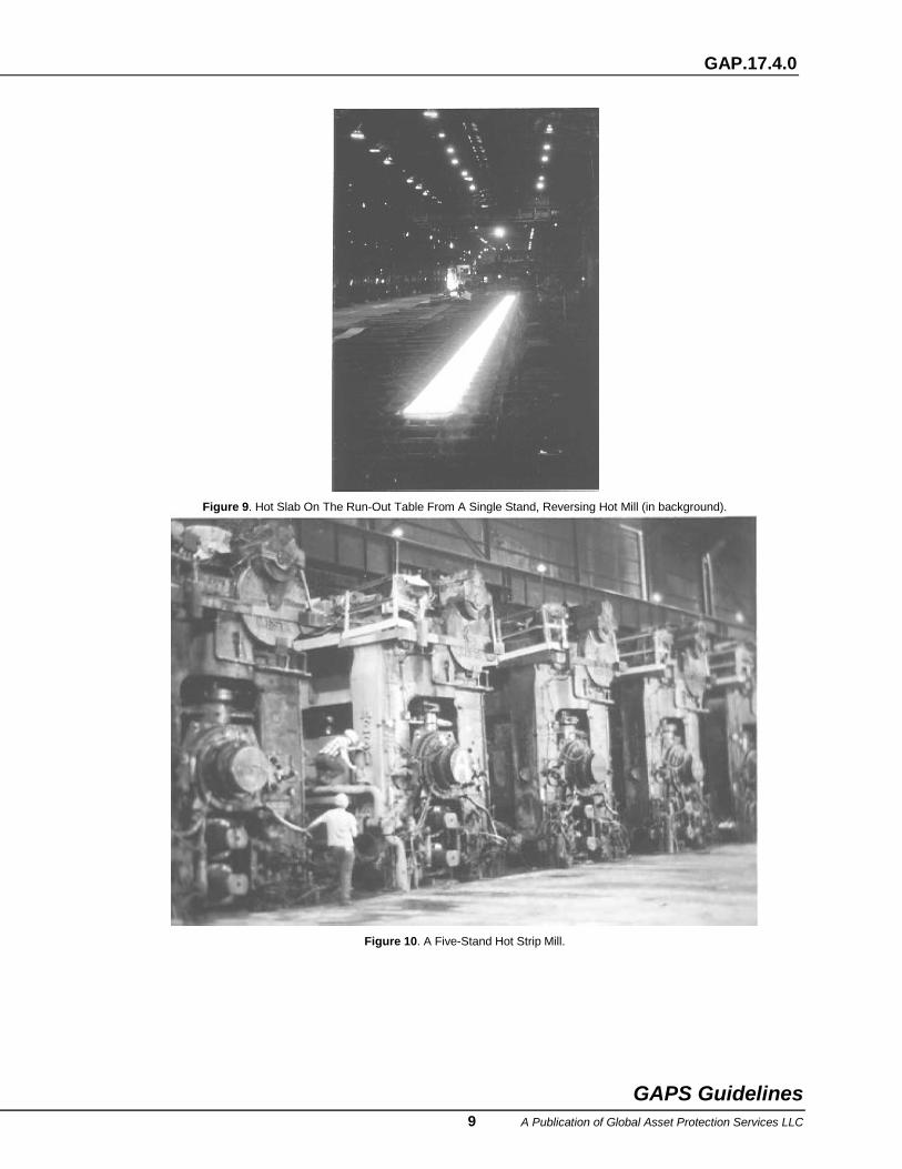
Figure 9. Hot Slab On The Run-Out Table From A Single Stand, Reversing Hot Mill (in background).
Figure 10. A Five-Stand Hot Strip Mill.
GAPS Guidelines 9 A Publication of Global Asset Protection Services LLC
GAP.17.4.0
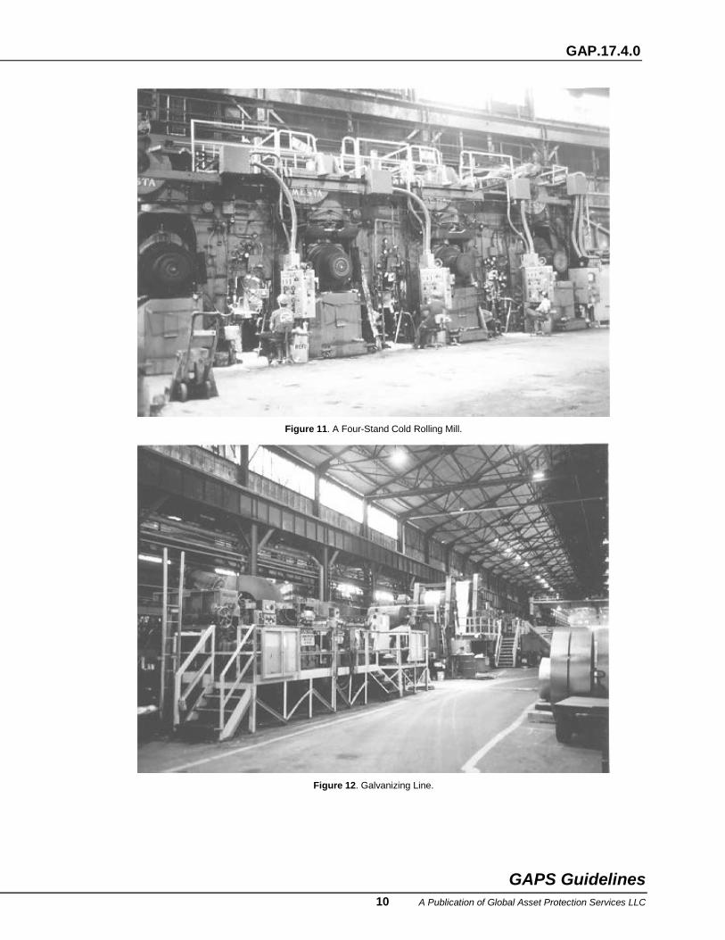
Figure 11. A Four-Stand Cold Rolling Mill.
Figure 12. Galvanizing Line.
GAPS Guidelines 10 A Publication of Global Asset Protection Services LLC
GAP.17.4.0
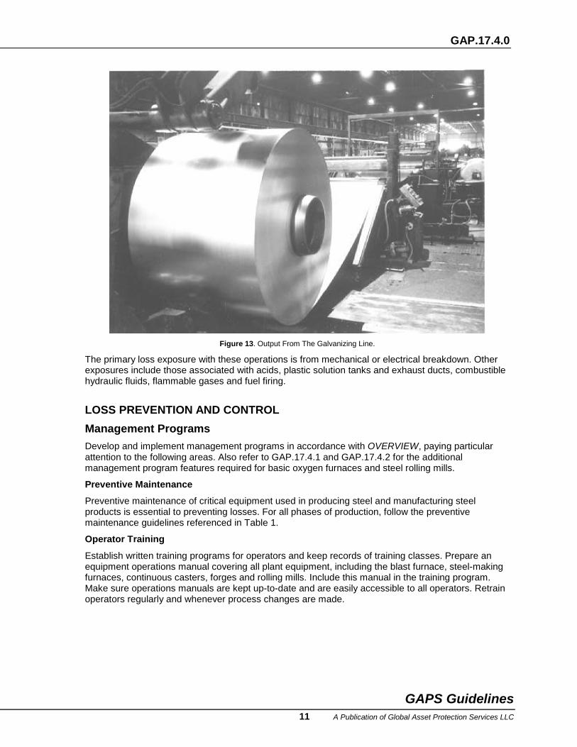
Figure 13. Output From The Galvanizing Line.
The primary loss exposure with these operations is from mechanical or electrical breakdown. Other exposures include those associated with acids, plastic solution tanks and exhaust ducts, combustible hydraulic fluids, flammable gases and fuel firing.
LOSS PREVENTION AND CONTROL Management Programs Develop and implement management programs in accordance with OVERVIEW, paying particular attention to the following areas. Also refer to GAP.17.4.1 and GAP.17.4.2 for the additional management program features required for basic oxygen furnaces and steel rolling mills.
Preventive Maintenance
Preventive maintenance of critical equipment used in producing steel and manufacturing steel products is essential to preventing losses. For all phases of production, follow the preventive maintenance guidelines referenced in Table 1.
Operator Training
Establish written training programs for operators and keep records of training classes. Prepare an equipment operations manual covering all plant equipment, including the blast furnace, steel-making furnaces, continuous casters, forges and rolling mills. Include this manual in the training program. Make sure operations manuals are kept up-to-date and are easily accessible to all operators. Retrain operators regularly and whenever process changes are made.
GAPS Guidelines 11 A Publication of Global Asset Protection Services LLC

GAP.17.4.0
TABLE 1 Preventive Maintenance Of Steel Manufacturing Equipment
Equipment Guidelines Turbine-generators and turboblowers GAP.1.3.0 Transformers GAP.5.9.1 Refractory Perform weekly thermographic inspection Water cooling systems Control water quality and measure piping thickness. Inspect at
furnace relines Forging and extrusion presses Follow manufacturers’ recommendations for metals inspection
and nondestructive testing
Pre-emergency Planning
Provide and properly store and maintain spare operating elements for turbine-generators, crushers, conveyors, ladles, pumps, motors, gears and all other equipment critical to maintaining operations.
Acquaint emergency response teams with possible emergency scenarios for each process in the facility and train them how to respond to these scenarios. Drill the emergency response teams regularly.
Hazard Evaluation
Evaluate the effect on process equipment and mechanical and electrical services of incidents involving each part of the process. Based on this evaluation, design or protect the process to minimize the effects of these incidents. For example, provide adequate diking, backup electrical power, non-electrically dependent cooling water supplies and backup cooling water systems as needed to prevent incidents from resulting in a major loss of production.
Mining Use noncombustible construction for buildings. Cut off boiler and electric generating rooms with 3 h rated fire barrier walls and 3 h rated automatic closing fire doors. Cut off office and switchgear areas with 2 h rated walls and 1!/2 h rated automatic closing fire doors.
Reserve an adequate portion of the mine water supply for fire protection. See GAP.14.1.1.0 for information on the amount of water that should be reserved. Provide a separate system of looped underground fire protection mains in accordance with NFPA 24 and GAP.14.5.0.1 to supply hydrants and sprinkler systems. Space hydrants at 250 ft (75 m) intervals.
Provide automatic wet or dry pipe sprinkler systems in building areas with combustible occupancy in accordance with NFPA 13 and GAP.12.1.1.0. Such buildings commonly found in mining operations include conveyor transfer houses and buildings for maintenance, water treatment, offices and storage.
Protect belt conveyors in accordance with GAP.9.3.1. Protect drive motor enclosures with double-shot carbon dioxide systems designed in accordance with NFPA 12 and GAP.13.3.1. Locate hydrants and/or hose connections to permit hose streams to reach all parts of the conveyor gallery.
Provide automatic water or foam extinguishing systems for hydraulic and lube oil reservoirs for crushers and conveyors in accordance with NFPA 13, NFPA 15 or NFPA 16 and with GAP.12.1.1.0 or GAP.12.3.1.1, as appropriate. Design systems for 0.25 gpm/ft2 (10.2 L/min/m2). Dike, drain and trap oil reservoirs. Protect hydraulic systems in accordance with GAP.9.2.4.
Arrange and protect fossil fired electric generating equipment and hydroelectric generating equipment in accordance with NFPA 850 and GAP.17.12.1. Protect turbine-generators as specified in GAP.6.1.1.0.3. Protect power transformers in accordance with GAP.5.9.2.
In mining, boilers may be used for building heat or for generating electrical power. Install combustion safeguards for these boilers in accordance with NFPA 85 and GAP.4.0.1.
Store and handle explosives in accordance with the Bureau of Mines regulations and NFPA 495. Protect bulk storage of flammable and combustible liquids in accordance with NFPA 30 and
GAPS Guidelines 12 A Publication of Global Asset Protection Services LLC
GAP.17.4.0
GAP.8.1.0. Handle these liquids in safety containers and keep only one day’s supply outside the bulk storage facilities.
Provide portable dry chemical or CO2 extinguishers on mobile mining equipment. Choose the size, type and location of extinguishers as appropriate for the equipment power supplies, oil systems and mechanical operations. Consider providing fixed protection for large, important mobile equipment.
Protect hydraulic oil systems in accordance with GAP.9.2.4.
Reduction Protect belt conveyors in accordance with GAP.9.3.1. Protect drive motor enclosures with double-shot carbon dioxide systems designed in accordance with NFPA 12 and GAP.13.3.1. Locate hydrants and/or hose connections to permit hose streams to reach all parts of the conveyor gallery.
Install combustion safeguards for sintering furnaces, pelletizer furnaces and coke ovens in accordance with NFPA 86 and GAP.4.0.1. Provide controls appropriate for the fuels being burned in the blast furnace stoves and tuyères.
Provide main and backup cooling water systems for the blast furnace. If electric pumps provide both cooling water systems, supply power to each pump from separate utility sources. Monitor the quality and flow of the cooling water.
Protect turboblower hydraulic systems in accordance with GAP.9.2.4. Turboblower drives could be turbines or large electric motors. Protect the turbine drives in accordance with GAP.6.1.1.0.3 and GAP.17.12.1 and the motor enclosures with double-shot carbon dioxide systems.
Provide automatic water or foam extinguishing systems for hydraulic and lube oil reservoirs for turboblowers in accordance with NFPA 13, NFPA 15 or NFPA 16 and with GAP.12.1.1.0 or GAP.12.3.1.1, as appropriate. Design systems for 0.25 gpm/ft2 (10.2 L/min/m2) over the protected area. Dike, drain and trap oil reservoirs. Protect hydraulic fluid systems in accordance with GAP.9.2.4.
Monitor the temperature beneath the blast furnace refractory floor with thermocouples. Place the thermocouples far enough apart vertically to yield a meaningful temperature gradient for the type of refractory and arrange the thermocouples so they may be replaced between furnace shutdowns.
When the blast furnace is relined, check all cooling water system components and repair and replace components as necessary. The cooling system should be designed and maintained to last longer than the longest expected operating period of the furnace. Blast furnaces commonly operate from four to ten years between relinings.
Use noncombustible bags in bag houses, or provide sprinkler protection. Refer to GAP.9.3.2.1 for information about the design and protection of precipitators.
Locate coke by-products plants as far away as practical from all other buildings and structures. Protect distillation operations in accordance with GAP.9.6.2.1.
Refining Use noncombustible construction for buildings. Cut off boiler and electric generating rooms with 3 hour rated fire barrier walls and 3 hour rated automatic closing fire doors. Cut off office and switchgear areas with 2 hour rated walls and 1!/2 hour rated automatic closing fire doors.
Arrange pits, dikes and diversionary dikes to protect the building and equipment from molten metal spills. Use refractory to protect surfaces exposed to molten metal spills. Use refractory or a suitable heat-resistant coating to protect building structural members exposed to molten metal spills. Coating materials meeting UL 1709 for 1!/2 hours and ASTM E 119 criteria for 3 hours are acceptable.
Provide automatic wet or dry pipe sprinkler systems in areas with combustible occupancy in accordance with NFPA 13 and GAP.12.1.1.0.
Provide automatic sprinkler or water spray protection for hydraulic and lube oil reservoirs for furnace tilting mechanisms in accordance with NFPA 13, NFPA 15 or NFPA 16 and with GAP.12.1.1.0 or
GAPS Guidelines 13 A Publication of Global Asset Protection Services LLC
GAP.17.4.0
GAP.12.3.1.1, as appropriate. Design systems for 0.25 gpm/ft2 (10.2 L/min/m2) over the protected area. Dike, drain and trap oil reservoirs. Protect hydraulic fluid systems in accordance with GAP.9.2.4.
Cover scrap for the steel-making furnaces and keep it as free from moisture as possible. Control all incoming scrap through secure gates, and monitor the scrap for radioactivity. Protect BOFs in accordance with GAP.17.4.1. Provide main and backup cooling water sources for furnaces and tun dishes. Monitor the quality and flow of the cooling water.
Use noncombustible bags in bag houses, or provide sprinkler protection. Refer to GAP.9.3.2.1 for information about the design and protection of precipitators.
In refining operations, boilers may be used for building heat or for generating electrical power. Install combustion safeguards for these boilers in accordance with NFPA 85 and GAP.4.0.1.
Protect power, rectifier and arc furnace transformers in accordance with GAP.5.9.2. Provide at least one spare transformer of each type used. If transformers in the plant vary and they are not interchangeable, more spares should be kept.
Arrange and protect fossil fired electric generating equipment, cable tunnels and cable spreading rooms in accordance with NFPA 850 and GAP.17.12.1.
Fabrication Use noncombustible construction for buildings. Cut off boiler rooms and warehouse areas with 3 hour rated fire barrier walls and 3 hour rated automatic closing fire doors. Cut off office and switchgear areas with 2 hour rated walls and 1!/2 hour rated automatic closing fire doors.
Provide automatic sprinkler protection in areas with combustible occupancy in accordance with NFPA 13 and GAP.12.1.1.0.
Arrange pits, dikes and diversionary dikes to protect the building and equipment from molten metal spills. Use refractory to protect surfaces exposed to molten metal spills. Use refractory or a suitable heat-resistant coating to protect building structural members exposed to molten metal spills. Coating materials meeting UL 1709 and ASTM E 119 criteria for three hours are acceptable.
Provide automatic sprinkler or water spray protection for hydraulic and lube oil reservoirs in accordance with NFPA 13, NFPA 15 or NFPA 16 and with GAP.12.1.1.0 or GAP.12.3.1.1, as appropriate. Design systems for 0.25 gpm/ft2 (10.2 L/min/m2) over the protected area. Dike, drain and trap oil reservoirs. Protect hydraulic fluid systems in accordance with GAP.9.2.4.
Install combustion safeguards on holding furnaces in accordance with NFPA 86 and GAP.4.0.1.
Rolling presents the highest loss exposure of the steel fabrication methods and it requires specialized protection. Refer to GAP.17.4.2 for a complete treatment of the loss prevention and control measures needed for these operations.
Properly protect finishing operations. Provide automatic sprinklers for plastic ductwork on pickling lines in accordance with GAP.2.3.2. Install combustion safeguards on annealing ovens in accordance with in accordance with NFPA 86 and GAP.4.0.1. Protect hydraulic and lube oil systems and other systems using combustible liquids in accordance with GAP.17.4.2.
PHOTOGRAPHS
Taken at National Steel Corporation, Granite City, IL. Courtesy of National Steel Corporation.
GAPS Guidelines 14 A Publication of Global Asset Protection Services LLC
Related Documents