The Red Book ™ B1. Steel Frame Wall Systems. Contents. SUBJECT PAGE Steel Stud Selection Tables B2 Introduction B4 Design Considerations B4 Installation B6 Components B7 System Specifications Single Stud B9 Staggered Stud B16 Double Stud B20 Shaft Wall B23 Resilient Mount & Furring B24 SecurityWall ™ B25 External Walls B28 Laminated Services Walls B33 Cinema Wall B34 Column & Beam B35 System Installation Details B36 to B46 SECTION ‘B’

Welcome message from author
This document is posted to help you gain knowledge. Please leave a comment to let me know what you think about it! Share it to your friends and learn new things together.
Transcript

The Red Book™B1.
Steel Frame Wall Systems.
Contents.SUBJECT PAGE
Steel Stud Selection Tables B2
Introduction B4
Design Considerations B4
Installation B6
Components B7
System Specifications
Single Stud B9
Staggered Stud B16
Double Stud B20
Shaft Wall B23
Resilient Mount & Furring B24
SecurityWall™ B25
External Walls B28
Laminated Services Walls B33
Cinema Wall B34
Column & Beam B35
System Installation Details B36 to B46
SECTION ‘B’

B2. The Red Book™
TABLE B1. MAXIMUM WALL HEIGHT WITH RONDO LIPPED STEEL STUDS.NON LOADBEARING INTERNAL WALLS – NON FIRE RATED OR FIRE RATED.
Walls Generally (Load UDL = 0.25kPa).
2.783.213.392.60
3.353.743.783.30
3.944.164.533.60
4.174.44.534.30
3.734.164.323.80
4.405.035.264.10
4.675.235.435.00
4.604.985.214.40
4.855.525.734.80
5.125.765.945.80
5.207.017.207.00
5.407.657.807.80
0.50 0.50 0.75 1.15 0.55 0.75 1.15 0.55 0.75 1.15 0.75 1.15
6mm
13mm
16mm
CSR 080 (–/180/180 only)
Stud Depth mm
Stud Gauge BMT
Min. Lining Thickness
Wall Frame
and Lining
Configuration
64
Maximum Wall Height (m)
76 92 15051
NOTES TO TABLES B1 AND B2.1. The values in Tables B1 and B2 have been prepared and published by Rondo Building Services Pty Ltd.2. Single stud walls, lined both sides exceeding 4.4m height must have a minimum of one row of noggings.3. Staggered stud wall systems use 64mm lipped studs and a 92mm width track with the CSR Gyprock® Staggered Stud Clip.
600mm max. cts
2.32
2.32
2.32
2.84
2.84
2.84
3.00
3.16
3.16
3.00
3.54
3.54
3.00
3.27
3.27
3.00
3.86
3.86
3.00
4.08
4.08
3.00
3.73
3.73
3.00
4.24
4.24
3.00
4.73
4.73
3.00
5.73
5.73
3.00
5.99
6.86
–
–
–
–
2.80
3.48
3.00
3.98
–
–
–
–
–
–
–
–
–
–
–
–
–
–
–
–
One Row Nogging6mm
Two Rows Nogging6mm
Three Rows Nogging6mm
6mm
BOXED STUDS6mm
600mm max. cts
600mm max. cts
TABLE B2. MAXIMUM WALL HEIGHT WITH RONDO LIPPED STEEL STUDS.NON LOADBEARING WALLS – NON FIRE RATED OR FIRE RATED.Walls of Shafts and Fire Isolated Exits Generally (Load UDL = 0.35kPa).
Stud Selection Tables.
600mm max. cts
2.432.823.012.60
2.953.313.463.30
3.503.763.853.60
3.713.954.004.00
3.283.673.813.80
3.814.444.634.10
3.814.614.484.48
3.814.424.634.40
3.814.865.024.80
3.815.075.215.21
3.815.716.396.39
3.815.716.926.92
0.50 0.50 0.75 1.15 0.55 0.75 1.15 0.55 0.75 1.15 0.75 1.15
6mm
13mm
16mm
CSR 080 (–/180/180 only)
Stud Depth mm
Stud Gauge BMT
Min. Lining Thickness
Wall Frame
and Lining
Configuration
64
Maximum Wall Height (m)
76 92 15051
600mm max. cts
–
–
2.54
–
2.96
–
3.0
3.17
2.67
2.67
3.0
3.24
3.0
3.65
2.67
2.67
3.0
3.76
3.0
3.81
3.0
3.81
3.0
3.81
One Row Nogging6mm
Two Rows Nogging6mm
600mm max. cts
–
–
2.4
3.20
2.6
3.55
2.8
–
–
–
–
–
–
–
–
–
–
–
–
–
–
–
–
–
6mm
BOXED STUDS6mm
300mm max. cts
300mm max. cts
Boxed Studs
300mm max. cts
300mm max. cts
Boxed Studs
Tables B1 to B3 provide maximum height information for non-loadbearing steel frame wall systems lined withGyprock® plasterboard and/or CSR Fibre Cement. Table B4 provides maximum height information for Gyprock®
Shaftwall Systems. Table B5 provides wall spanning information for Laminated Services Systems. Span tables forSecurityWall™, Cinema Wall and ExpressWall™ systems are provided in the respective installation guides.
For information on stud selection for loadbearing walls, or alternative lateral pressures, please contact the stud manufacturer.

The Red Book™B3.
TABLE B3. MAXIMUM WALL HEIGHT FOR STAGGERED STEEL STUDS LINED TWO SIDES OR WALLS LINED ONE SIDE ONLY.
NON LOADBEARING WALLS.
Walls Generally (Load UDL = 0.25kPa).
TABLE B4. MAXIMUM WALL HEIGHT FOR SHAFTWALL SYSTEMS.
88 88 88 120 120 120
Stud Depth/BMT mm
Min. Cavity Width
Min. Lining Thickness
Wall Frame
and Lining
Configuration
Wall Frame
and Lining
Configuration
Rondo
Stud
Type
64CH55
102CH55
FRL –/60/60
System CSR970
FRL –/120/120
System CSR971, 972
3.60
4.30
3.20
4.00
3.60
4.30
3.40
4.30
Maximum Wall Height (m)
3.50
3.86
3.50
3.87
4.17
3.87
4.11
4.37
4.11
4.82
4.96
4.82
4.93
5.44
5.30
4.93
5.81
5.65
13mm GYPROCKFYRCHEK
2 layers x 13mmGYPROCK FYRCHEK
9mm CSR Fibre Cement
Wallboard
StramitSupplier
Steel Stud Type TH64075
64/0.75
TH64100
64/1.00
TH64120
64/1.20
TH96075
96/0.75
TH96100
96/1.00
TH96120
96/1.20
600mm max. cts
300mm max. cts
300mm max. cts
600mm max. cts
76 85 85 144 144
Stud Depth/BMT mm
Min. Cavity Width
Min. Lining Thickness
Wall Frame
and Lining
Configuration Maximum Wall Height (m)
3.00
3.00
3.00
3.44
3.50
3.44
3.71
3.90
3.71
4.93
5.90
5.90
4.93
6.40
6.00
13mm GYPROCKFYRCHEK
2 layers x 13mmGYPROCK FYRCHEK
9mm CSR Fibre Cement
Wallboard
Rhino Steel LysaghtSupplier
Steel Stud Type UniSpan 53
53/–
TS61-075
61/0.75
TS61-100
61/1.00
TS120-070
120/0.70
TS120-090
120/0.90
600mm max. cts
300mm max. cts
300mm max. cts
UDL 0.25kPa UDL 0.35kPa UDL 0.25kPa UDL 0.35kPa
Maximum Wall Height (m)
B4. The Red Book™
Introduction.CSR Gyprock and Fibre Cement (GFC) steel
frame wall systems use zinc coated steel componentswith one or more layers of Gyprock® plasterboardand/or CSR Fibre Cement linings fixed to one orboth sides. A wide choice of systems is available forboth fire rated and non-fire rated applications in non-loadbearing and loadbearing situations.
These wall systems are most often used in internalnon-loadbear ing applications, in commercial,industr ial, institutional, residential and high-r iseresidential construction. Systems are also available forexternal walls
DesignConsiderations.
STRUCTURAL DESIGN.
All walls must be designed for the applied loads.Guidance is given for the selection of Rondo studs andLysaght, Stramit or UniSpan top hat sections for non-loadbearing internal walls only.
Load bear ing walls and walls subject to windpressures shall be appropriately designed to meet therelevant Australian Standards or construction manuals.
Non Loadbearing Walls.
Maximum wall height and the required stud sizemay be selected from Table B1 to B5, appropriate forthe selected system. These walls are designed for lateralloads only, using the composite action of the frame andsheeting.
Non load bearing walls in this manual have beendesigned as follows:
• Minimum design pressure of 0.25kPa and amaximum deflection of (height ÷ 240) or 30mmmaximum. (Based on BCA Specification C1.8, 3.4(b))
• Fire rated walls lined with GYPROCKFYRCHEK with studs selected from Table C2meet the requirements of BCA Specification C1.8Clause 3.4 – Walls generally.
Internal wall studs are friction fitted into trackswith no clearance at the bottom and a minimumallowance for vertical expansion of 15mm at the top.Where vertical building movement is expected anadditional gap is required. In this case deflection headtracks must be used. Refer to Section ‘Z’ for details.
Staggered stud walls using top hats are fixed to thebase track and use Rondo Nº126/152 clip at the toptrack. Staggered stud walls using Rondo C studs mustuse the CSR staggered stud clip to restrain the studfrom twisting.
Wall tracks must be fixed to floors and ceilings at600mm maximum centres. Each plate fixing isrequired to withstand a shear load of 0.75kN for aUDL of 0.25kPa and 1.1kN for UDL of 0.35kPa.
Tall residential buildings often have operable doorsand windows, resulting in internal walls being subjectto wind pressure. In these cases, walls must be designedfor the appropriate loads.
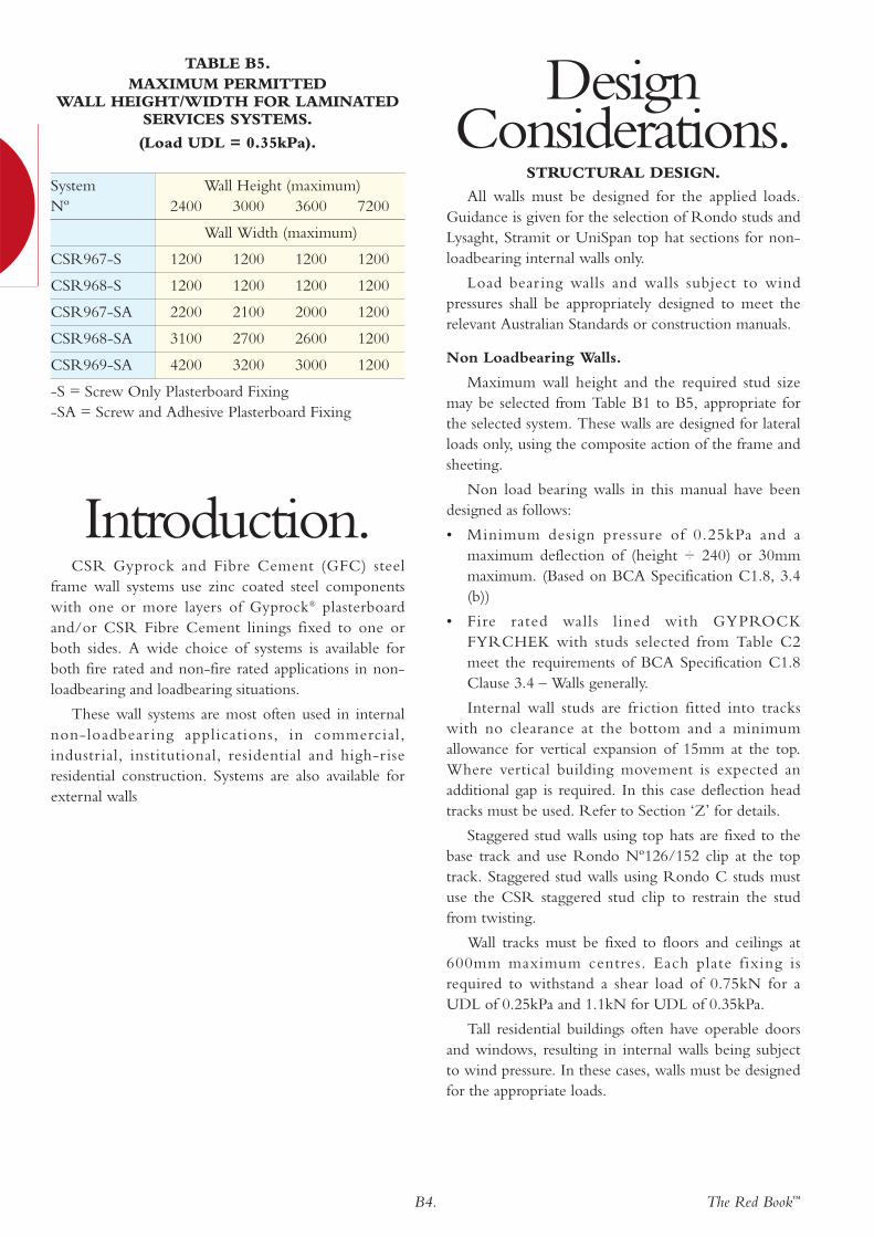
System Wall Height (maximum)Nº 2400 3000 3600 7200
Wall Width (maximum)
CSR967-S 1200 1200 1200 1200
CSR968-S 1200 1200 1200 1200
CSR967-SA 2200 2100 2000 1200
CSR968-SA 3100 2700 2600 1200
CSR969-SA 4200 3200 3000 1200
-S = Screw Only Plasterboard Fixing-SA = Screw and Adhesive Plasterboard Fixing
TABLE B5. MAXIMUM PERMITTED
WALL HEIGHT/WIDTH FOR LAMINATEDSERVICES SYSTEMS.
(Load UDL = 0.35kPa).
The Red Book™B5.
Loadbearing Walls.
Walls designed as load bearing and lined withGYPROCK FYRCHEK meet the requirements ofBCA Specification C1.8 Clause 3.4 – Walls generally.
The building designer must ensure load bearingwalls have been designed:
• To resist all applied loads.
• To be in accordance with AS4600 or AS3740.
• Assuming no contr ibution to axial strength isrequired of the wall linings.
To meet the stated Fire Resistance Level (FRL), theaxial load capacity of some wall systems is reduced.This is a result of the steel weakening at hightemperature during a fire test. The systems are notedwith an Axial Capacity Reduction percentage(ACR%). For these systems, the designer must increasethe applied loads before selecting stud size tocompensate for the axial capacity reduction percentage,as shown in the system specification.
Studs are to be placed at 600mm maximum centreswith nogging provided as detailed in Table B1 or B2,or as noted in the system table.
The capacity of head and base tracks for wallssubject to wind loads must be checked. Typically, studsare cleated at head and base with a Rondo anglebracket. Contact Rondo for more information ondesigning walls subject to wind loads.
FIRE RESISTANCE.
The steel frame wall systems in this manual aresuitable for the stated FRL when designed inaccordance with the structural considerations above.
CSR GFC fire rated steel stud wall systems havebeen designed with fire protection that limits thetemperature of the steel framing to a maximum of450°C at the fire resistance level (FRL) stated.Therefore the structural design of the framing needonly provide for normal temperature conditions, andno additional consideration of fire rating is required. Insome systems this temperature is exceeded and theaxial capacity of the stud must be reduced tocompensate for the loss of strength. The percentagereduction is noted for each affected systems. For moreinformation regarding the fire resistance of steel studwalls, refer to BRANZ assessment FAR 2357.
To protect structural steel beams and columns thatare entirely within a wall, the FRL of the wall systemmust be at least equivalent to that required by thestructural member. For example, a wall system withFRL 90/90/90 provides FRL 90/–/– for a steelcolumn within the wall.
Framing & Lining.
Steel framed walls required to have an FRL mustcomply with the following:
• Framing must be made from steel of BMT 0.5mmto 2.0mm.
• Wall plates must be fixed to the fire rated supportstructure with steel fasteners such as expansionanchors, easy drive masonry anchors and powerdriven fasteners.
• Plasterboard must be screw or nail fixed only,adhesive is not permitted.
• In wet areas, Gyprock Fyrchek MR™ must be usedin lieu of Gyprock Fyrchek™.
• For single layer applications, butt joints must bebacked by either a stud or nogging. This is notrequired for recessed joints.
• For double layer vertically sheeted applications, buttjoints may be reinforced using laminating screwswithout the need for framing support.
• Joints in the outer layer of all systems lined withplasterboard or Wallboard must be set withGyprock® paper tape. As a minimum, a single coatfinish may be used.
• Joints in external systems lined with CSR FibreCement Texture Base Sheet must be set with thetape and compound recommended for the texturecoating system
• Spacing of girts in horizontally framed systems mustbe as shown in installation detail FIG B17.
For general installation information, refer to FIGB2 to B18.
For information on frame design and detailing,including treatment at junctions, sub floor and roofareas, cavity barriers and penetrations, refer to Section‘Z’ of this manual, and brochure NºGYP544, GyprockSteel Frame Wall Systems.
The Fire Resistance Level (FRL) of the systemsdetailed in this section will not be detr imentallyaffected by;
• Increasing the thickness of the wall.
• Increasing the cross-sectional dimensions of theframing elements.
• Decreasing the stud spacing.
• Decreasing the fixing centres of wall sheet materials.
• The inclusion of bulk cavity insulation materialssuch as Glasswool, Rockwool and Polyester.
• The use of Fyrchek™ MR plasterboard in lieu ofFyrchek™ plasterboard of the same thickness.
• Additional layers of plasterboard or CSR FibreCement.

B6. The Red Book™
• Wall curved in plan with a radius of curvature noless than 3m.
• The addition of a timber cladding.
• The addition of any other cladding meeting BCASpec C1.1 Clause 2.4.
Caulking.
To attain the specified FRL, all perimeter gaps andpenetrations must be carefully and completely filledwith appropriate caulking material. CSR Gyprock FireMastic or other tested fire and acoustic rated materialof equivalent or better performance must be used.
Details for fire sealing of penetrations is given inSection ‘Z’.
Vermiculite plaster has no capacity to accommodatebuilding movement and may not be suitable for use as ageneral purpose fire rated caulking. Its use is specified insome wall/ceiling junctions, refer to brochureNºGYP570, Gyprock® Ceiling Systems Installation Guide.
ACOUSTIC PERFORMANCE.
The acoustic performance of wall systems isexpressed in terms of Rw and Rw+Ctr whereappropriate. The performance of the as-built systemmay be affected by – sound flanking, the effectivenessof workmanship and caulking, the presence andtreatment of penetrations, and the inclusion ofstructural elements and bridging items. Refer toSection ‘A’ for detailed information on addressingthese issues.
General Notes.
• The acoustic performance of systems may beadversely affected by the use of studs with higherBMT or closer spacings than those specified, oradditional linings fixed with battens.
• The acoustic performance of CSR wall systems isnot adversely affected by the order of lining sheetsthat are fixed direct to framing. In non fire ratedsystems, to attain the stated acoustic performance,use CSR Gyprock Wet Area Acrylic Sealant, CSRGyprock Fire Mastic or other tested acoustic ratedmaterial of equivalent or better performance.
Installation.FRAMING.
CSR GFC recommends steel componentsmanufactured by Rondo Building Services Pty Ltd.Additional information on the steel components canbe obtained from the Rondo Building Services PtyLtd, telephone 1300 367 663. For information onLysaght, Stramit or UniSpan top hat sections, pleaserefer to the appropriate component manufacturer, andthe Gyprock® Steel Frame Wall Systems InstallationGuide, NºGYP544. Other steel components ofequivalent performance may be used, however it is theresponsibility of the manufacturer of the component tosubstantiate equivalent performance with therecommended component.
For detailed information on wall junctions,intersections, frame attachments and penetrations, referto Section ‘Z’ of this manual.
Walls curved in plan may be built with steel studframes. Selection information on stud centres andplasterboard thickness for various curvatures can befound in brochure NºGYP544, Gyprock® Steel FrameWall Systems.
WALLBOARD & PLASTERBOARD FIXING.
Walls may be built to achieve a particular ‘Level ofFinish’ as defined in AS/NZS2589.1. The Level ofFinish specified can have requirements for framealignment, jointing and back blocking methods, andsheet orientation. CSR Fibre Cement Wallboard andGyprock® plasterboard may be installed vertically orhorizontally, although for some Levels of Finishhorizontal sheeting must be used.
Walls lined with Gyprock® plasterboard or CSRFibre Cement Wallboard may be finished with tiles.For tiles greater than 32kg/m2 or over 6.5mmthickness, specific installation details apply. Refer tothe appropriate installation manual.
PLASTERBOARD JOINTING & FINISHING.
Refer to the Gyprock® Residential InstallationGuide, NºGYP547 and CSR Fibre Cement Wet AreaLining Systems, NºFC101 for detailed jointing andfinishing information.
It should be noted that:
• Multi-layered systems only require jointing andfinishing of the outer layer.
The Red Book™B7.
• It is a requirement of the BCA that a water resistanttaping compound, such as CSR Gyprock FibreCement Wet Area Base Coat be used at verticalwall junctions and horizontal and vertical jointswithin wet areas such as showers.
CONTROL JOINTS.
Control joints must be installed to allow forstructural movement. Allowance for movement mustbe made through the frame, lining and any tiles. Referto Section ‘Z’ of this manual for details.
Control joints must be installed at all constructionjoints in the building and at the following locations:
• Non-tiled internal walls with fibre cement outerlayer – at 7.2m maximum centres.
• Tiled internal walls with fibre cement outer layer –at 4.2m maximum centres.
• Walls with plasterboard outer layer – at 12mmaximum centres.
• External walls – refer to the appropriate installationmanual.
EXTERNAL WALLS.
Gyprock® GFC external wall systems rely on arange of cladding systems to provide weatherresistance. There is a range of effectiveness of thesesystems, and CSR Gyprock recommends the claddingbe installed with a drained cavity. Cavity systems allowdrainage and drying of any water that penetrates, andare known to have good long-term performance.
Sarking is also recommended to provide additionalweather protection to framing and lining.
External walls require specific design forcondensation control and energy efficiency, dependingon the climate and internal environment. ContactCSR Bradford for information on thermal insulationsystems and products.
Components.LINING & FIXING MATERIALS.
Refer to Section ‘A’ for detailed information onCSR Gyprock and Fibre Cement lining products,fixings, adhesive and accessories.
For details on CSR Fibre Cement Texture BaseSheet, refer to brochure NºFC122, CSR FibreCement Texture Base Sheet for Applied FinishSystems’
FRAMING.
CSR Gyprock and CSR Fibre Cement recommendsteel components manufactured by Rondo BuildingServices Pty Ltd. Additional information on the steelcomponents can be obtained from the Rondo BuildingServices Pty Ltd, telephone 1300 367 663.
For information on Lysaght, Stramit or UniSpantop hat sections, please refer to the appropr iatecomponent manufacturer, and the Gyprock® SteelFrame Wall Systems Installation Guide, NºGYP544.
Other steel components of equivalent performancemay be used, however it is the responsibility of themanufacturer of the component to substantiateequivalent performance with the recommendedcomponent.
B8. The Red Book™
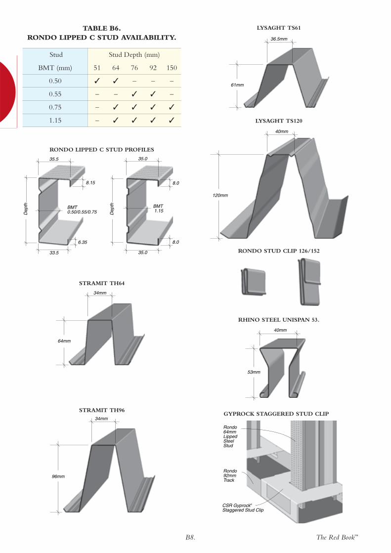
Stud Stud Depth (mm)
BMT (mm) 51 64 76 92 150
0.50 ✓ ✓ – – –
0.55 – – ✓ ✓ –
0.75 – ✓ ✓ ✓ ✓
1.15 – ✓ ✓ ✓ ✓
CSR Gyprock® Staggered Stud Clip
Rondo 92mm Track
Rondo 64mm Lipped Steel Stud
GYPROCK STAGGERED STUD CLIP
6.35
Dep
th
33.5 35.0
35.5
8.15
35.0
8.0
BMT0.50/0.55/0.75 D
epth
8.0
BMT 1.15
RONDO LIPPED C STUD PROFILES
RHINO STEEL UNISPAN 53.
STRAMIT TH64
STRAMIT TH96
53mm
40mm
64mm
34mm
RONDO STUD CLIP 126/152
96mm
34mm
120mm
40mm
LYSAGHT TS120
61mm
36.5mm
LYSAGHT TS61TABLE B6.RONDO LIPPED C STUD AVAILABILITY.

The Red Book™B9.
– / – / –
(a) Nil 41/30 42/32 43/33 43/34 45/37
(b) 50 Glasswool Partition batts 47/36 47/37 48/38 48/39 50/42
(c) 75 Glasswool Partition batts - 48/38 49/39 49/40 51/43
(d) ASB3/TSB3 Polyester batts 46/35 47/37 48/38 48/39 50/42
(e) 60 Soundscreen™ R1.6 batts RW - 48/38 49/39 49/40 51/43
WALL THICKNESS mm 81 94 106 122 180
CSR 030
SIDE ONE
• 1 x 10mm GYPROCKAQUACHEK plasterboard.
SIDE TWO
• 2 x 10mm GYPROCKSOUNDCHEKplasterboard.
– / – / –
(a) Nil 36/25 37/27 38/28 38/29 40/31
(b) 50 Glasswool Partition batts 42/31 42/32 43/33 43/34 45/36
(c) 75 Glasswool Partition batts - 43/33 44/34 44/35 46/37
(d) ASB3/TSB3 Polyester batts 41/30 42/32 43/33 43/34 45/36
(e) 60 Soundscreen™ R1.6 batts RW - 43/33 44/34 44/35 46/37
WALL THICKNESS mm 71 84 96 112 170
CSR 025
BOTH SIDES
• 1 x 10mm GYPROCKSOUNDCHEKplasterboard.
– / – / –
(a) Nil 44/35 45/36 45/36 46/38 48/40
(b) 50 Glasswool Partition batts 50/41 50/41 50/41 51/43 53/45
(c) 75 Glasswool Partition batts - 51/42 51/42 52/44 54/46
(d) ASB3/TSB3 Polyester batts 49/40 50/41 50/41 51/43 53/45
(e) 60 Soundscreen™ R1.6 batts RW - 51/42 51/42 52/44 54/46
WALL THICKNESS mm 103 116 128 144 202
CSR 020BOTH SIDES
• 2 x 13mm GYPROCKPlasterboard CD.
– / – / –
(a) Nil 40/29 41/30 42/32 42/32 44/35
(b) 50 Glasswool Partition batts 46/35 46/35 47/37 47/37 49/40
(c) 75 Glasswool Partition batts - 47/36 48/38 48/38 50/41
(d) ASB3/TSB3 Polyester batts 45/34 46/35 47/37 47/37 49/40
(e) 60 Soundscreen™ R1.6 batts RW - 47/36 48/38 48/38 50/41
WALL THICKNESS mm 90 103 115 131 189
CSR 015
SIDE ONE
• 1 x 13mm GYPROCKPlasterboard CD.
SIDE TWO
• 2 x 13mm GYPROCKPlasterboard CD.
– / – / –
(a) Nil 35/24 36/25 37/27 37/27 39/30
(b) 50 Glasswool Partition batts 41/30 41/30 42/32 42/32 45/36
(c) 75 Glasswool Partition batts - 42/31 43/33 43/33 45/36
(d) ASB3/TSB3 Polyester batts 40/29 41/30 42/32 42/32 45/36
(e) 60 Soundscreen™ R1.6 batts RW - 42/31 43/33 43/33 45/36
WALL THICKNESS mm 77 90 102 118 176
CSR 010BOTH SIDES
• 1 x 13mm GYPROCKPlasterboard CD.
– / – / –
(a) Nil 33/21 34/23 34/23 35/25 36/27
(b) 50 Glasswool Partition batts 39/27 39/28 39/28 40/30 41/32
(c) 75 Glasswool Partition batts - 40/29 40/29 41/31 42/33
(d) ASB3/TSB3 Polyester batts 38/26 39/28 39/28 40/30 41/32
(e) 60 Soundscreen™ R1.6 batts RW - 40/29 40/29 41/31 42/33
WALL THICKNESS mm 71 84 96 112 170
CSR 005BOTH SIDES
• 1 x 10mm GYPROCKPlasterboard CD.
ACOUSTICOPINION
PKA-A025
FRLReport/Opinion
SYSTEM Nº
WALL LININGS
SYSTEM SPECIFICATION TYPICAL LAYOUT
• Lining material as per system table.
• Steel Studs at 600mm maximum centres.
• Lining material as per system table.
NOTES:
Acoustic performance valid for studs of 0.50 to 0.80 BMT.
STUD DEPTH mm 51 64 76 92 150
CAVITY INFILL (Refer to Section ‘A’) Rw / Rw+Ctr
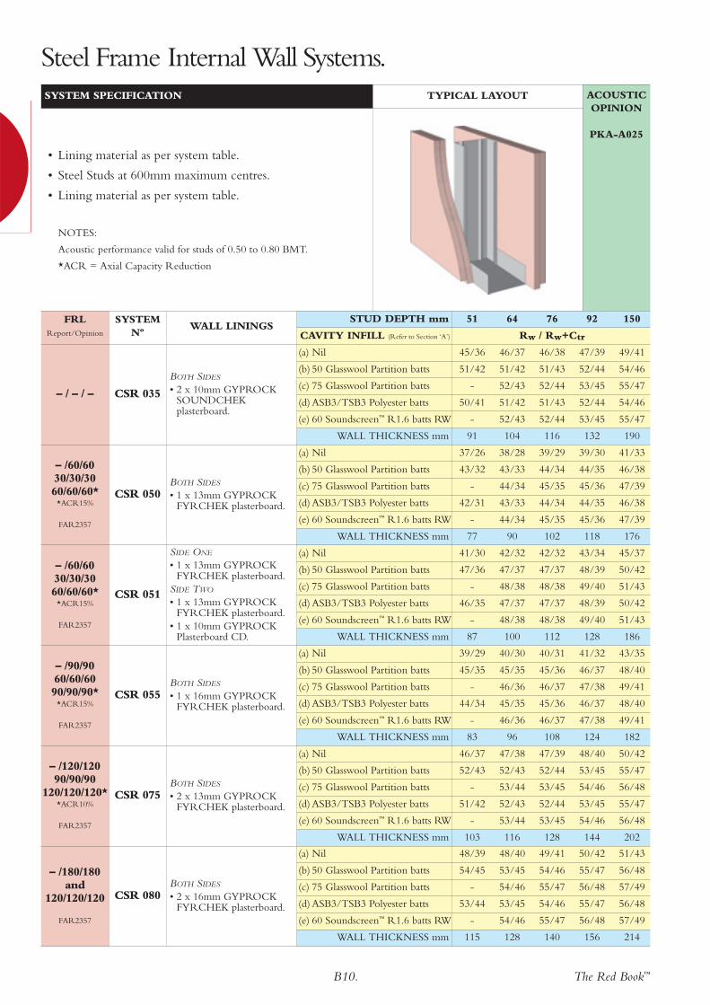
Steel Frame Internal Wall Systems.
B10. The Red Book™
– /180/180and
120/120/120
FAR2357
(a) Nil 48/39 48/40 49/41 50/42 51/43
(b) 50 Glasswool Partition batts 54/45 53/45 54/46 55/47 56/48
(c) 75 Glasswool Partition batts - 54/46 55/47 56/48 57/49
(d) ASB3/TSB3 Polyester batts 53/44 53/45 54/46 55/47 56/48
(e) 60 Soundscreen™ R1.6 batts RW - 54/46 55/47 56/48 57/49
WALL THICKNESS mm 115 128 140 156 214
CSR 080BOTH SIDES
• 2 x 16mm GYPROCKFYRCHEK plasterboard.
– /120/12090/90/90
120/120/120**ACR10%
FAR2357
(a) Nil 46/37 47/38 47/39 48/40 50/42
(b) 50 Glasswool Partition batts 52/43 52/43 52/44 53/45 55/47
(c) 75 Glasswool Partition batts - 53/44 53/45 54/46 56/48
(d) ASB3/TSB3 Polyester batts 51/42 52/43 52/44 53/45 55/47
(e) 60 Soundscreen™ R1.6 batts RW - 53/44 53/45 54/46 56/48
WALL THICKNESS mm 103 116 128 144 202
CSR 075BOTH SIDES
• 2 x 13mm GYPROCKFYRCHEK plasterboard.
– /90/9060/60/6090/90/90*
*ACR15%
FAR2357
(a) Nil 39/29 40/30 40/31 41/32 43/35
(b) 50 Glasswool Partition batts 45/35 45/35 45/36 46/37 48/40
(c) 75 Glasswool Partition batts - 46/36 46/37 47/38 49/41
(d) ASB3/TSB3 Polyester batts 44/34 45/35 45/36 46/37 48/40
(e) 60 Soundscreen™ R1.6 batts RW - 46/36 46/37 47/38 49/41
WALL THICKNESS mm 83 96 108 124 182
CSR 055BOTH SIDES
• 1 x 16mm GYPROCKFYRCHEK plasterboard.
– /60/6030/30/3060/60/60*
*ACR15%
FAR2357
(a) Nil 41/30 42/32 42/32 43/34 45/37
(b) 50 Glasswool Partition batts 47/36 47/37 47/37 48/39 50/42
(c) 75 Glasswool Partition batts - 48/38 48/38 49/40 51/43
(d) ASB3/TSB3 Polyester batts 46/35 47/37 47/37 48/39 50/42
(e) 60 Soundscreen™ R1.6 batts RW - 48/38 48/38 49/40 51/43
WALL THICKNESS mm 87 100 112 128 186
CSR 051
SIDE ONE
• 1 x 13mm GYPROCKFYRCHEK plasterboard.
SIDE TWO
• 1 x 13mm GYPROCKFYRCHEK plasterboard.
• 1 x 10mm GYPROCKPlasterboard CD.
– /60/6030/30/3060/60/60*
*ACR15%
FAR2357
(a) Nil 37/26 38/28 39/29 39/30 41/33
(b) 50 Glasswool Partition batts 43/32 43/33 44/34 44/35 46/38
(c) 75 Glasswool Partition batts - 44/34 45/35 45/36 47/39
(d) ASB3/TSB3 Polyester batts 42/31 43/33 44/34 44/35 46/38
(e) 60 Soundscreen™ R1.6 batts RW - 44/34 45/35 45/36 47/39
WALL THICKNESS mm 77 90 102 118 176
CSR 050BOTH SIDES
• 1 x 13mm GYPROCKFYRCHEK plasterboard.
– / – / –
(a) Nil 45/36 46/37 46/38 47/39 49/41
(b) 50 Glasswool Partition batts 51/42 51/42 51/43 52/44 54/46
(c) 75 Glasswool Partition batts - 52/43 52/44 53/45 55/47
(d) ASB3/TSB3 Polyester batts 50/41 51/42 51/43 52/44 54/46
(e) 60 Soundscreen™ R1.6 batts RW - 52/43 52/44 53/45 55/47
WALL THICKNESS mm 91 104 116 132 190
CSR 035
BOTH SIDES
• 2 x 10mm GYPROCKSOUNDCHEKplasterboard.
ACOUSTICOPINION
PKA-A025
FRLReport/Opinion
SYSTEM Nº
WALL LININGS
SYSTEM SPECIFICATION TYPICAL LAYOUT
• Lining material as per system table.
• Steel Studs at 600mm maximum centres.
• Lining material as per system table.
NOTES:
Acoustic performance valid for studs of 0.50 to 0.80 BMT.
*ACR = Axial Capacity Reduction
STUD DEPTH mm 51 64 76 92 150
CAVITY INFILL (Refer to Section ‘A’) Rw / Rw+Ctr
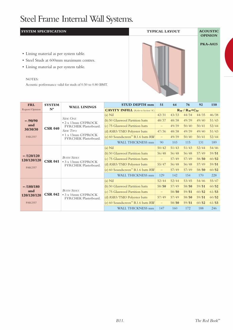
Steel Frame Internal Wall Systems.
The Red Book™B11.
– /180/180and
120/120/120
FAR2357
(a) Nil 52/44 52/44 53/45 54/46 55/47
(b) 50 Glasswool Partition batts 58/50 57/49 58/50 59/51 60/52
(c) 75 Glasswool Partition batts – 58/50 59/51 60/52 61/53
(d) ASB3/TSB3 Polyester batts 57/49 57/49 58/50 59/51 60/52
(e) 60 Soundscreen™ R1.6 batts RW – 58/50 59/51 60/52 61/53
WALL THICKNESS mm 147 160 172 188 246
CSR 042BOTH SIDES
• 3 x 16mm GYPROCKFYRCHEK Plasterboard.
– /120/120120/120/120
FAR2357
(a) Nil 50/42 51/43 51/43 52/44 54/46
(b) 50 Glasswool Partition batts 56/48 56/48 56/48 57/49 59/51
(c) 75 Glasswool Partition batts – 57/49 57/49 58/50 60/52
(d) ASB3/TSB3 Polyester batts 55/47 56/48 56/48 57/49 59/51
(e) 60 Soundscreen™ R1.6 batts RW – 57/49 57/49 58/50 60/52
WALL THICKNESS mm 129 142 154 170 228
CSR 041BOTH SIDES
• 3 x 13mm GYPROCKFYRCHEK Plasterboard.
– /90/90and
30/30/30
FAR2357
(a) Nil 42/31 43/33 44/34 44/35 46/38
(b) 50 Glasswool Partition batts 48/37 48/38 49/39 49/40 51/43
(c) 75 Glasswool Partition batts – 49/39 50/40 50/41 52/44
(d) ASB3/TSB3 Polyester batts 47/36 48/38 49/39 49/40 51/43
(e) 60 Soundscreen™ R1.6 batts RW – 49/39 50/40 50/41 52/44
WALL THICKNESS mm 90 103 115 131 189
CSR 040
SIDE ONE
• 2 x 13mm GYPROCKFYRCHEK Plasterboard.
SIDE TWO
• 1 x 13mm GYPROCKFYRCHEK Plasterboard.
ACOUSTICOPINION
PKA-A025
FRLReport/Opinion
SYSTEM Nº
WALL LININGS
SYSTEM SPECIFICATION TYPICAL LAYOUT
• Lining material as per system table.
• Steel Studs at 600mm maximum centres.
• Lining material as per system table.
NOTES:
Acoustic performance valid for studs of 0.50 to 0.80 BMT.
STUD DEPTH mm 51 64 76 92 150
CAVITY INFILL (Refer to Section ‘A’) Rw / Rw+Ctr
Steel Frame Internal Wall Systems.

B12. The Red Book™
– / – / –
(a) Nil 38/27 39/28 39/29 40/30 42/33
(b) 50 Glasswool Partition batts 44/33 44/33 44/34 45/35 47/38
(c) 75 Glasswool Partition batts - 45/34 45/35 46/36 48/39
(d) ASB3/TSB3 Polyester batts 43/32 44/33 44/34 45/35 47/38
(e) 60 Soundscreen™ R1.6 batts RW - 45/34 45/35 46/36 48/39
WALL THICKNESS mm 73 86 98 114 172
CSR 606
SIDE ONE
• 1 x 9mm CSR FibreCement Wallboard.
SIDE TWO
• 1 x 13mm GYPROCKPlasterboard CD.
– / – / –
(a) Nil 36/25 36/25 37/27 38/28 39/30
(b) 50 Glasswool Partition batts 42/31 41/30 42/32 43/33 44/35
(c) 75 Glasswool Partition batts - 42/31 43/33 44/34 45/36
(d) ASB3/TSB3 Polyester batts 41/30 41/30 42/32 43/33 44/35
(e) 60 Soundscreen™ R1.6 batts RW - 42/31 43/33 44/34 45/36
WALL THICKNESS mm 70 83 95 111 169
CSR 605
SIDE ONE
• 1 x 6mm CSR FibreCement Wallboard.
SIDE TWO
• 1 x 13mm GYPROCKPlasterboard CD.
– / – / –
(a) Nil 36/25 37/27 37/27 38/28 40/31
(b) 50 Glasswool Partition batts 42/31 42/32 42/32 43/33 45/36
(c) 75 Glasswool Partition batts - 43/33 43/33 44/34 46/37
(d) ASB3/TSB3 Polyester batts 41/30 42/32 42/32 43/33 45/36
(e) 60 Soundscreen™ R1.6 batts RW - 43/33 43/33 44/34 46/37
WALL THICKNESS mm 67 80 92 108 166
CSR 031
SIDES ONE
• 1 x 6mm CSR FibreCement Wallboard
SIDES TWO
• 1 x 10mm GYPROCKSOUNDCHEKplasterboard.
– / – / –
(a) Nil 42/33 43/34 43/34 44/36 46/38
(b) 50 Glasswool Partition batts 48/39 48/39 48/39 49/41 51/43
(c) 75 Glasswool Partition batts - 49/40 49/40 50/42 52/44
(d) ASB3/TSB3 Polyester batts 47/38 48/39 48/39 49/41 51/43
(e) 60 Soundscreen™ R1.6 batts RW - 49/40 49/40 50/42 52/44
WALL THICKNESS mm 75 88 100 116 174
CSR 602BOTH SIDES
• 1 x 12mm CSR FibreCement Wallboard.
– / – / –
(a) Nil 40/30 41/32 41/32 42/33 44/36
(b) 50 Glasswool Partition batts 46/36 46/37 46/37 47/38 49/41
(c) 75 Glasswool Partition batts - 47/38 47/38 48/39 50/42
(d) ASB3/TSB3 Polyester batts 45/35 46/37 46/37 47/38 49/41
(e) 60 Soundscreen™ R1.6 batts RW - 47/38 47/38 48/39 50/42
WALL THICKNESS mm 69 82 94 110 168
CSR 601BOTH SIDES
• 1 x 9mm CSR FibreCement Wallboard.
– / – / –
(a) Nil 36/25 37/27 37/27 38/28 40/31
(b) 50 Glasswool Partition batts 42/31 42/32 42/32 43/33 45/36
(c) 75 Glasswool Partition batts - 43/33 43/33 44/34 46/37
(d) ASB3/TSB3 Polyester batts 41/30 42/32 42/32 43/33 45/36
(e) 60 Soundscreen™ R1.6 batts RW - 43/33 43/33 44/34 46/37
WALL THICKNESS mm 63 76 88 104 162
CSR 600BOTH SIDES
• 1 x 6mm CSR FibreCement Wallboard.
ACOUSTICOPINION
PKA-A025
FRLReport/Opinion
SYSTEM Nº
WALL LININGS
SYSTEM SPECIFICATION TYPICAL LAYOUT
• Lining material as per system table.
• Steel Studs at 600mm maximum centres.
• Lining material as per system table.
NOTES:
Acoustic performance valid for studs of 0.50 to 0.80 BMT.
STUD DEPTH mm 51 64 76 92 150
CAVITY INFILL (Refer to Section ‘A’) Rw / Rw+Ctr
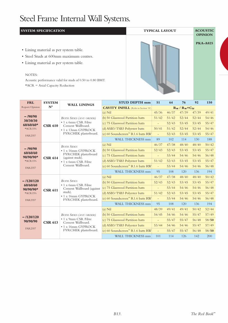
Steel Frame Internal Wall Systems.
The Red Book™B13.
– /120/12090/90/90
FAR2357
(a) Nil 48/39 49/41 49/41 50/42 52/44
(b) 50 Glasswool Partition batts 54/45 54/46 54/46 55/47 57/49
(c) 75 Glasswool Partition batts - 55/47 55/47 56/48 58/50
(d) ASB3/TSB3 Polyester batts 53/44 54/46 54/46 55/47 57/49
(e) 60 Soundscreen™ R1.6 batts RW - 55/47 55/47 56/48 58/50
WALL THICKNESS mm 101 114 126 142 200
CSR 613
BOTH SIDES (ANY ORDER)• 1 x 9mm CSR Fibre
Cement Wallboard.• 1 x 16mm GYPROCK
FYRCHEK plasterboard.
– /120/12060/60/6090/90/90*
*ACR15%
FAR2357
(a) Nil 46/37 47/38 48/40 48/40 50/42
(b) 50 Glasswool Partition batts 52/43 52/43 53/45 53/45 55/47
(c) 75 Glasswool Partition batts - 53/44 54/46 54/46 56/48
(d) ASB3/TSB3 Polyester batts 51/42 52/43 53/45 53/45 55/47
(e) 60 Soundscreen™ R1.6 batts RW - 53/44 54/46 54/46 56/48
WALL THICKNESS mm 95 108 120 136 194
CSR 611
BOTH SIDES
• 1 x 6mm CSR FibreCement Wallboard (againststuds).
• 1 x 16mm GYPROCKFYRCHEK plasterboard.
– /90/9060/60/6090/90/90*
*ACR15%
FAR2357
(a) Nil 46/37 47/38 48/40 48/40 50/42
(b) 50 Glasswool Partition batts 52/43 52/43 53/45 53/45 55/47
(c) 75 Glasswool Partition batts - 53/44 54/46 54/46 56/48
(d) ASB3/TSB3 Polyester batts 51/42 52/43 53/45 53/45 55/47
(e) 60 Soundscreen™ R1.6 batts RW - 53/44 54/46 54/46 56/48
WALL THICKNESS mm 95 108 120 136 194
CSR 614
BOTH SIDES
• 1 x 16mm GYPROCKFYRCHEK plasterboard(against studs).
• 1 x 6mm CSR FibreCement Wallboard.
– /90/9030/30/3060/60/60*
*ACR15%
FAR2357
(a) Nil 45/36 46/37 47/39 47/39 49/41
(b) 50 Glasswool Partition batts 51/42 51/42 52/44 52/44 54/46
(c) 75 Glasswool Partition batts - 52/43 53/45 53/45 55/47
(d) ASB3/TSB3 Polyester batts 50/41 51/42 52/44 52/44 54/46
(e) 60 Soundscreen™ R1.6 batts RW - 52/43 53/45 53/45 55/47
WALL THICKNESS mm 89 102 114 130 188
CSR 610
BOTH SIDES (ANY ORDER)• 1 x 6mm CSR Fibre
Cement Wallboard.• 1 x 13mm GYPROCK
FYRCHEK plasterboard.
ACOUSTICOPINION
PKA-A025
FRLReport/Opinion
SYSTEM Nº
WALL LININGS
SYSTEM SPECIFICATION TYPICAL LAYOUT
• Lining material as per system table.
• Steel Studs at 600mm maximum centres.
• Lining material as per system table.
NOTES:
Acoustic performance valid for studs of 0.50 to 0.80 BMT.
*ACR = Axial Capacity Reduction
STUD DEPTH mm 51 64 76 92 150
CAVITY INFILL (Refer to Section ‘A’) Rw / Rw+Ctr
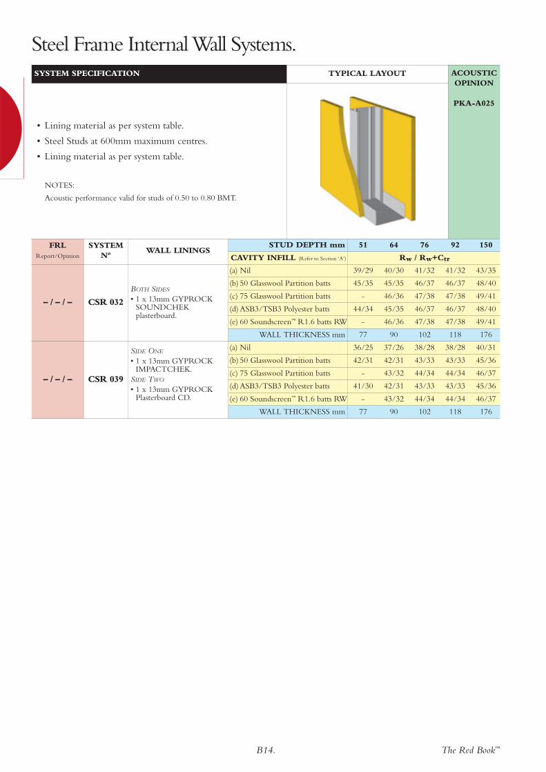
Steel Frame Internal Wall Systems.
B14. The Red Book™
– / – / –
(a) Nil 36/25 37/26 38/28 38/28 40/31
(b) 50 Glasswool Partition batts 42/31 42/31 43/33 43/33 45/36
(c) 75 Glasswool Partition batts - 43/32 44/34 44/34 46/37
(d) ASB3/TSB3 Polyester batts 41/30 42/31 43/33 43/33 45/36
(e) 60 Soundscreen™ R1.6 batts RW - 43/32 44/34 44/34 46/37
WALL THICKNESS mm 77 90 102 118 176
CSR 039
SIDE ONE
• 1 x 13mm GYPROCKIMPACTCHEK.
SIDE TWO
• 1 x 13mm GYPROCKPlasterboard CD.
– / – / –
(a) Nil 39/29 40/30 41/32 41/32 43/35
(b) 50 Glasswool Partition batts 45/35 45/35 46/37 46/37 48/40
(c) 75 Glasswool Partition batts - 46/36 47/38 47/38 49/41
(d) ASB3/TSB3 Polyester batts 44/34 45/35 46/37 46/37 48/40
(e) 60 Soundscreen™ R1.6 batts RW - 46/36 47/38 47/38 49/41
WALL THICKNESS mm 77 90 102 118 176
CSR 032
BOTH SIDES
• 1 x 13mm GYPROCKSOUNDCHEKplasterboard.
ACOUSTICOPINION
PKA-A025
FRLReport/Opinion
SYSTEM Nº
WALL LININGS
SYSTEM SPECIFICATION TYPICAL LAYOUT
• Lining material as per system table.
• Steel Studs at 600mm maximum centres.
• Lining material as per system table.
NOTES:
Acoustic performance valid for studs of 0.50 to 0.80 BMT.
STUD DEPTH mm 51 64 76 92 150
CAVITY INFILL (Refer to Section ‘A’) Rw / Rw+Ctr
Steel Frame InternalWall Systems.

The Red Book™B15.
Fire rated fromlined side only
– /120/120and
120/120/120
FAR2357
(a) Nil 36/34
PLASTERBOARD
MASS kg/m2 37.5
CSR 093 • 3 x 16mm GYPROCKFYRCHEK plasterboard.
Fire rated fromlined side only
– /90/90and
90/90/90
FAR2357
(a) Nil 35/33
PLASTERBOARD
MASS kg/m2 31.5
CSR 092 • 3 x 13mm GYPROCKFYRCHEK plasterboard.
Fire rated fromlined side only
– /60/60and
60/60/60
FAR2357
(a) Nil 33/31
PLASTERBOARD
MASS kg/m2 25.0
CSR 091 • 2 x 16mm GYPROCKFYRCHEK plasterboard.
Fire rated fromlined side only
– /30/30and
30/30/30
FAR2357
(a) Nil 31/29
PLASTERBOARD
MASS kg/m2 21.0
CSR 090 • 2 x 13mm GYPROCKFYRCHEK plasterboard.
– / – / –
(a) Nil 31/30
PLASTERBOARD
MASS kg/m2 13.0
CSR 089 • 1 x 13mm GYPROCKSOUNDCHEK plasterboard.
ACOUSTICOPINION
PKA-A025
FRLReport/Opinion
SYSTEM Nº
WALL LININGS LAYOUT
SYSTEM SPECIFICATION
• Steel Studs at 600mm maximum centres.
• Lining material as per system table.
STUD DEPTH mm ALL
CAVITY INFILL Rw / Rw+Ctr
Steel Frame Internal Wall Systems.

B16. The Red Book™
– / – / –
(a) Nil 44/36 46/38 50/42 52/44
(b) 50 Glasswool Partition batts 52/44 54/46 58/50 60/52
(c) 75 Glasswool Partition batts 53/45 55/47 59/51 61/53
(d) ASB3/TSB3 Polyester batts 52/44 54/46 58/50 60/52
(e) 60 Soundscreen™ R1.6 batts RW 53/45 55/47 59/51 61/53
WALL THICKNESS mm 116 132 190 240
CSR 130
BOTH SIDES
• 2 x 10mm GYPROCKSOUNDCHEKplasterboard.
– / – / –
(a) Nil 39/30 41/32 45/37 47/39
(b) 50 Glasswool Partition batts 47/38 49/40 53/45 55/47
(c) 75 Glasswool Partition batts 48/39 50/41 54/46 56/48
(d) ASB3/TSB3 Polyester batts 47/38 49/40 53/45 55/47
(e) 60 Soundscreen™ R1.6 batts RW 48/39 50/41 54/46 56/48
WALL THICKNESS mm 102 118 176 226
CSR 131
BOTH SIDES
• 1 x 13mm GYPROCKSOUNDCHEKplasterboard.
– / – / –
(a) Nil 40/30 42/32 46/37 49/41
(b) 50 Glasswool Partition batts 48/38 50/40 54/45 57/49
(c) 75 Glasswool Partition batts 49/39 51/41 55/46 58/50
(d) ASB3/TSB3 Polyester batts 48/38 50/40 54/45 57/49
(e) 60 Soundscreen™ R1.6 batts RW 49/39 51/41 55/46 58/50
WALL THICKNESS mm 102 118 176 226
CSR 135
SIDE ONE
• 1 x 6mm CSR FibreCement Wallboard..
SIDE TWO
• 2 x 10mm GYPROCKSOUNDCHEKplasterboard.
– / – / –
(a) Nil 36/26 38/29 42/33 44/36
(b) 50 Glasswool Partition batts 44/34 46/37 50/41 52/44
(c) 75 Glasswool Partition batts 45/35 47/38 51/42 53/45
(d) ASB3/TSB3 Polyester batts 44/34 46/37 50/41 52/44
(e) 60 Soundscreen™ R1.6 batts RW 45/35 47/38 51/42 53/45
WALL THICKNESS mm 96 112 170 220
CSR 125
BOTH SIDES
• 1 x 10mm GYPROCKSOUNDCHEKplasterboard.
– / – / –
(a) Nil 35/25 37/27 41/32 44/36
(b) 50 Glasswool Partition batts 43/33 45/35 49/40 52/44
(c) 75 Glasswool Partition batts 44/34 46/36 50/41 53/45
(d) ASB3/TSB3 Polyester batts 43/33 45/35 49/40 52/44
(e) 60 Soundscreen™ R1.6 batts RW 44/34 46/36 50/41 53/45
WALL THICKNESS mm 102 118 176 226
CSR 110
BOTH SIDES
• 1 x 13mm GYPROCKPlasterboard CD.
– / – / –
(a) Nil 33/22 35/25 39/30 41/32
(b) 50 Glasswool Partition batts 41/30 43/33 47/38 49/40
(c) 75 Glasswool Partition batts 42/31 44/34 48/39 50/41
(d) ASB3/TSB3 Polyester batts 41/30 43/33 47/38 49/40
(e) 60 Soundscreen™ R1.6 batts RW 42/31 44/34 48/39 50/41
WALL THICKNESS mm 96 112 170 220
CSR 105BOTH SIDES
• 1 x 10mm GYPROCKPlasterboard CD.
ACOUSTICOPINION
PKA-A025
Does NOT meet BCA
DiscontinuousConstruction
FRLReport/Opinion
SYSTEM Nº
WALL LININGS
SYSTEM SPECIFICATION TYPICAL LAYOUT
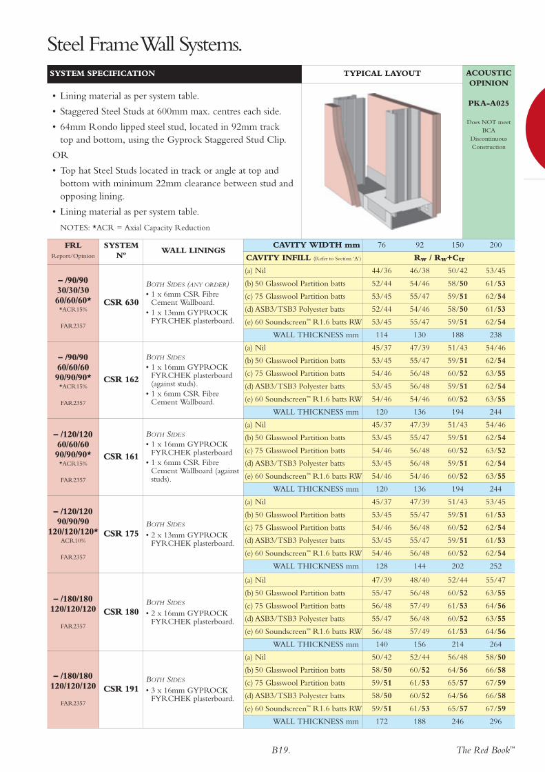
• Lining material as per system table.
• Staggered Steel Studs at 600mm maximum centres eachside.
• 64mm Rondo lipped steel stud, located in 92mm tracktop and bottom, using the Gyprock Staggered Stud Clip.
OR
• Top hat Steel Studs located in track or angle at top andbottom with minimum 22mm clearance between stud andopposing lining.
• Lining material as per system table.
CAVITY WIDTH mm 76 92 150 200
CAVITY INFILL (Refer to Section ‘A’) Rw / Rw+Ctr
Steel Frame Internal Wall Systems.

The Red Book™B17.
– / – / –
(a) Nil 37/27 39/29 43/34 46/38
(b) 50 Glasswool Partition batts 45/35 47/37 51/42 54/46
(c) 75 Glasswool Partition batts 46/36 48/38 52/43 55/47
(d) ASB3/TSB3 Polyester batts 45/35 47/37 51/42 54/46
(e) 60 Soundscreen™ R1.6 batts RW 46/36 48/38 52/43 55/47
WALL THICKNESS mm 98 114 172 222
CSR 633
SIDE ONE
• 1 x 9mm CSR FibreCement Wallboard.
SIDE TWO
• 1 x 13mm GYPROCKPlasterboard CD.
– / – / –
(a) Nil 36/26 38/28 42/33 45/37
(b) 50 Glasswool Partition batts 44/34 46/36 50/41 53/45
(c) 75 Glasswool Partition batts 45/35 47/37 51/42 55/46
(d) ASB3/TSB3 Polyester batts 44/34 46/36 50/41 53/45
(e) 60 Soundscreen™ R1.6 batts RW 45/35 47/37 51/42 54/46
WALL THICKNESS mm 102 118 176 226
CSR 632
SIDE ONE
• 1 x 13mm GYPROCKIMPACTCHEK.
SIDE TWO
• 1 x 13mm GYPROCKPlasterboard CD.
– / – / –
(a) Nil 35/25 37/27 41/32 44/36
(b) 50 Glasswool Partition batts 43/33 45/35 49/40 52/44
(c) 75 Glasswool Partition batts 44/34 46/36 50/41 53/45
(d) ASB3/TSB3 Polyester batts 43/33 45/35 49/40 52/44
(e) 60 Soundscreen™ R1.6 batts RW 44/34 46/36 50/41 53/45
WALL THICKNESS mm 95 111 169 219
CSR 631
SIDE ONE
• 1 x 6mm CSR FibreCement Wallboard.
SIDE TWO
• 1 x 13mm GYPROCKPlasterboard CD.
– / – / –
(a) Nil 39/30 41/32 45/37 48/40
(b) 50 Glasswool Partition batts 47/38 49/40 53/45 56/48
(c) 75 Glasswool Partition batts 48/39 50/41 54/46 57/49
(d) ASB3/TSB3 Polyester batts 47/38 49/40 53/45 56/48
(e) 60 Soundscreen™ R1.6 batts RW 48/39 50/41 54/46 57/49
WALL THICKNESS mm 94 110 168 218
CSR 620BOTH SIDES
• 1 x 9mm CSR FibreCement Wallboard.
ACOUSTICOPINION
PKA-A025
Does NOT meet BCA
DiscontinuousConstruction
FRLReport/Opinion
SYSTEM Nº
WALL LININGS
SYSTEM SPECIFICATION TYPICAL LAYOUT
• Lining material as per system table.
• Staggered Steel Studs at 600mm maximum centres eachside.
• 64mm Rondo lipped steel stud, located in 92mm track topand bottom, using the Gyprock Staggered Stud Clip.
OR
• Top hat Steel Studs located in track or angle at top andbottom with minimum 22mm clearance between stud andopposing lining.
• Lining material as per system table.
CAVITY WIDTH mm 76 92 150 200
CAVITY INFILL (Refer to Section ‘A’) Rw / Rw+Ctr
Steel Frame InternalWall Systems.

B18. The Red Book™
– /120/12090/90/90
FAR2357
(a) Nil 47/39 49/41 53/45 55/47
(b) 50 Glasswool Partition batts 55/47 57/49 61/53 61/55
(c) 75 Glasswool Partition batts 56/48 58/50 62/54 64/56
(d) ASB3/TSB3 Polyester batts 55/47 57/49 61/53 63/55
(e) 60 Soundscreen™ R1.6 batts RW 56/48 58/50 62/54 64/56
WALL THICKNESS mm 126 142 200 250
CSR 160
BOTH SIDES (ANY ORDER)• 1 x 16mm GYPROCK
FYRCHEK plasterboard.• 1 x 9mm CSR Fibre
Cement Wallboard.
– /90/9060/60/6090/90/90*
*ACR15%
FAR2357
(a) Nil 43/34 44/35 49/41 51/43
(b) 50 Glasswool Partition batts 51/42 52/43 57/49 59/51
(c) 75 Glasswool Partition batts 56/43 53/44 58/50 60/52
(d) ASB3/TSB3 Polyester batts 51/42 52/43 57/49 59/51
(e) 60 Soundscreen™ R1.6 batts RW 52/43 53/44 58/50 60/52
WALL THICKNESS mm 121 137 195 245
CSR 157
SIDE ONE
• 1 x 16mm GYPROCKFYRCHEK plasterboard.
SIDE TWO
• 1 x 16mm GYPROCKFYRCHEK plasterboard.
• 1 x 13mm GYPROCKFYRCHEK plasterboard.
– /90/9060/60/6090/90/90*
*ACR15%
FAR2357
(a) Nil 39/30 40/31 44/36 47/39
(b) 50 Glasswool Partition batts 47/38 48/39 52/44 55/47
(c) 75 Glasswool Partition batts 48/39 49/40 53/45 56/48
(d) ASB3/TSB3 Polyester batts 47/38 48/39 52/44 55/47
(e) 60 Soundscreen™ R1.6 batts RW 48/39 49/40 53/45 56/48
WALL THICKNESS mm 108 124 182 232
CSR 155BOTH SIDES
• 1 x 16mm GYPROCKFYRCHEK plasterboard.
– /60/6030/30/3060/60/60*
*ACR15%
FAR2357
(a) Nil 41/31 43/34 47/39 49/41
(b) 50 Glasswool Partition batts 49/39 51/42 55/47 57/49
(c) 75 Glasswool Partition batts 50/40 52/43 56/48 58/50
(d) ASB3/TSB3 Polyester batts 49/39 51/42 52/47 57/49
(e) 60 Soundscreen™ R1.6 batts RW 50/40 52/43 56/48 58/50
WALL THICKNESS mm 115 131 189 239
CSR 154
SIDE ONE
• 1 x 13mm GYPROCKFYRCHEK plasterboard.
SIDE TWO
• 1 x 13mm GYPROCKFYRCHEK plasterboard.
• 1 x 13mm GYPROCKPlasterboard CD.
– /90/9030/30/30
FAR2357
(a) Nil 42/32 43/34 47/39 50/42
(b) 50 Glasswool Partition batts 50/40 51/42 55/47 58/50
(c) 75 Glasswool Partition batts 51/41 52/43 56/48 59/51
(d) ASB3/TSB3 Polyester batts 50/40 51/42 55/47 58/50
(e) 60 Soundscreen™ R1.6 batts RW 51/41 52/43 56/48 59/51
WALL THICKNESS mm 115 131 189 239
CSR 152
SIDE ONE
• 1 x 13mm GYPROCKFYRCHEK plasterboard.
SIDE TWO
• 2 x 13mm GYPROCKFYRCHEK plasterboard.
– /60/6030/30/3060/60/60*
*ACR15%
FAR2357
(a) Nil 37/27 39/30 43/35 45/37
(b) 50 Glasswool Partition batts 45/35 47/38 51/43 53/45
(c) 75 Glasswool Partition batts 46/36 48/39 52/44 54/46
(d) ASB3/TSB3 Polyester batts 45/35 47/38 51/43 53/45
(e) 60 Soundscreen™ R1.6 batts RW 46/36 48/39 52/44 54/46
WALL THICKNESS mm 102 118 176 226
CSR 150BOTH SIDES
• 1 x 13mm GYPROCKFYRCHEK plasterboard.
ACOUSTICOPINION
PKA-A025
Does NOT meet BCA
DiscontinuousConstruction
FRLReport/Opinion
SYSTEM Nº
WALL LININGS
SYSTEM SPECIFICATION TYPICAL LAYOUT
• Lining material as per system table.
• Staggered Steel Studs at 600mm max. centres each side.
• 64mm Rondo lipped steel stud, located in 92mm tracktop and bottom, using the Gyprock Staggered Stud Clip.
OR
• Top hat Steel Studs located in track or angle at top andbottom with minimum 22mm clearance between stud andopposing lining.
• Lining material as per system table.
NOTES: *ACR = Axial Capacity Reduction
CAVITY WIDTH mm 76 92 150 200
CAVITY INFILL (Refer to Section ‘A’) Rw / Rw+Ctr
Steel FrameWall Systems.
The Red Book™B19.
– /180/180120/120/120
FAR2357
(a) Nil 50/42 52/44 56/48 58/50
(b) 50 Glasswool Partition batts 58/50 60/52 64/56 66/58
(c) 75 Glasswool Partition batts 59/51 61/53 65/57 67/59
(d) ASB3/TSB3 Polyester batts 58/50 60/52 64/56 66/58
(e) 60 Soundscreen™ R1.6 batts RW 59/51 61/53 65/57 67/59
WALL THICKNESS mm 172 188 246 296
CSR 191BOTH SIDES
• 3 x 16mm GYPROCKFYRCHEK plasterboard.
– /180/180120/120/120
FAR2357
(a) Nil 47/39 48/40 52/44 55/47
(b) 50 Glasswool Partition batts 55/47 56/48 60/52 63/55
(c) 75 Glasswool Partition batts 56/48 57/49 61/53 64/56
(d) ASB3/TSB3 Polyester batts 55/47 56/48 60/52 63/55
(e) 60 Soundscreen™ R1.6 batts RW 56/48 57/49 61/53 64/56
WALL THICKNESS mm 140 156 214 264
CSR 180BOTH SIDES
• 2 x 16mm GYPROCKFYRCHEK plasterboard.
– /120/120 90/90/90
120/120/120*ACR10%
FAR2357
(a) Nil 45/37 47/39 51/43 53/45
(b) 50 Glasswool Partition batts 53/45 55/47 59/51 61/53
(c) 75 Glasswool Partition batts 54/46 56/48 60/52 62/54
(d) ASB3/TSB3 Polyester batts 53/45 55/47 59/51 61/53
(e) 60 Soundscreen™ R1.6 batts RW 54/46 56/48 60/52 62/54
WALL THICKNESS mm 128 144 202 252
CSR 175BOTH SIDES
• 2 x 13mm GYPROCKFYRCHEK plasterboard.
– /120/12060/60/6090/90/90*
*ACR15%
FAR2357
(a) Nil 45/37 47/39 51/43 54/46
(b) 50 Glasswool Partition batts 53/45 55/47 59/51 62/54
(c) 75 Glasswool Partition batts 54/46 56/48 60/52 63/52
(d) ASB3/TSB3 Polyester batts 53/45 56/48 59/51 62/54
(e) 60 Soundscreen™ R1.6 batts RW 54/46 54/46 60/52 63/55
WALL THICKNESS mm 120 136 194 244
CSR 161
BOTH SIDES
• 1 x 16mm GYPROCKFYRCHEK plasterboard
• 1 x 6mm CSR FibreCement Wallboard (againststuds).
– /90/9060/60/6090/90/90*
*ACR15%
FAR2357
(a) Nil 45/37 47/39 51/43 54/46
(b) 50 Glasswool Partition batts 53/45 55/47 59/51 62/54
(c) 75 Glasswool Partition batts 54/46 56/48 60/52 63/55
(d) ASB3/TSB3 Polyester batts 53/45 56/48 59/51 62/54
(e) 60 Soundscreen™ R1.6 batts RW 54/46 54/46 60/52 63/55
WALL THICKNESS mm 120 136 194 244
CSR 162
BOTH SIDES
• 1 x 16mm GYPROCKFYRCHEK plasterboard(against studs).
• 1 x 6mm CSR FibreCement Wallboard.
– /90/9030/30/3060/60/60*
*ACR15%
FAR2357
(a) Nil 44/36 46/38 50/42 53/45
(b) 50 Glasswool Partition batts 52/44 54/46 58/50 61/53
(c) 75 Glasswool Partition batts 53/45 55/47 59/51 62/54
(d) ASB3/TSB3 Polyester batts 52/44 54/46 58/50 61/53
(e) 60 Soundscreen™ R1.6 batts RW 53/45 55/47 59/51 62/54
WALL THICKNESS mm 114 130 188 238
CSR 630
BOTH SIDES (ANY ORDER)• 1 x 6mm CSR Fibre
Cement Wallboard.• 1 x 13mm GYPROCK
FYRCHEK plasterboard.
ACOUSTICOPINION
PKA-A025
Does NOT meet BCA
DiscontinuousConstruction
FRLReport/Opinion
SYSTEM Nº
WALL LININGS
SYSTEM SPECIFICATION TYPICAL LAYOUT
• Lining material as per system table.
• Staggered Steel Studs at 600mm max. centres each side.
• 64mm Rondo lipped steel stud, located in 92mm tracktop and bottom, using the Gyprock Staggered Stud Clip.
OR
• Top hat Steel Studs located in track or angle at top andbottom with minimum 22mm clearance between stud andopposing lining.
• Lining material as per system table.
NOTES: *ACR = Axial Capacity Reduction
CAVITY WIDTH mm 76 92 150 200
CAVITY INFILL (Refer to Section ‘A’) Rw / Rw+Ctr
Steel FrameWall Systems.
B20. The Red Book™
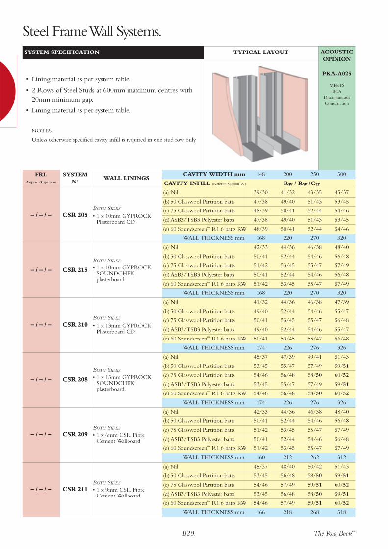
– / – / –
(a) Nil 45/37 48/40 50/42 51/43
(b) 50 Glasswool Partition batts 53/45 56/48 58/50 59/51
(c) 75 Glasswool Partition batts 54/46 57/49 59/51 60/52
(d) ASB3/TSB3 Polyester batts 53/45 56/48 58/50 59/51
(e) 60 Soundscreen™ R1.6 batts RW 54/46 57/49 59/51 60/52
WALL THICKNESS mm 166 218 268 318
CSR 211BOTH SIDES
• 1 x 9mm CSR FibreCement Wallboard.
– / – / –
(a) Nil 42/33 44/36 46/38 48/40
(b) 50 Glasswool Partition batts 50/41 52/44 54/46 56/48
(c) 75 Glasswool Partition batts 51/42 53/45 55/47 57/49
(d) ASB3/TSB3 Polyester batts 50/41 52/44 54/46 56/48
(e) 60 Soundscreen™ R1.6 batts RW 51/42 53/45 55/47 57/49
WALL THICKNESS mm 160 212 262 312
CSR 209BOTH SIDES
• 1 x 6mm CSR FibreCement Wallboard.
– / – / –
(a) Nil 45/37 47/39 49/41 51/43
(b) 50 Glasswool Partition batts 53/45 55/47 57/49 59/51
(c) 75 Glasswool Partition batts 54/46 56/48 58/50 60/52
(d) ASB3/TSB3 Polyester batts 53/45 55/47 57/49 59/51
(e) 60 Soundscreen™ R1.6 batts RW 54/46 56/48 58/50 60/52
WALL THICKNESS mm 174 226 276 326
CSR 208
BOTH SIDES
• 1 x 13mm GYPROCKSOUNDCHEKplasterboard.
– / – / –
(a) Nil 41/32 44/36 46/38 47/39
(b) 50 Glasswool Partition batts 49/40 52/44 54/46 55/47
(c) 75 Glasswool Partition batts 50/41 53/45 55/47 56/48
(d) ASB3/TSB3 Polyester batts 49/40 52/44 54/46 55/47
(e) 60 Soundscreen™ R1.6 batts RW 50/41 53/45 55/47 56/48
WALL THICKNESS mm 174 226 276 326
CSR 210BOTH SIDES
• 1 x 13mm GYPROCKPlasterboard CD.
– / – / –
(a) Nil 42/33 44/36 46/38 48/40
(b) 50 Glasswool Partition batts 50/41 52/44 54/46 56/48
(c) 75 Glasswool Partition batts 51/42 53/45 55/47 57/49
(d) ASB3/TSB3 Polyester batts 50/41 52/44 54/46 56/48
(e) 60 Soundscreen™ R1.6 batts RW 51/42 53/45 55/47 57/49
WALL THICKNESS mm 168 220 270 320
CSR 215
BOTH SIDES
• 1 x 10mm GYPROCKSOUNDCHEKplasterboard.
– / – / –
(a) Nil 39/30 41/32 43/35 45/37
(b) 50 Glasswool Partition batts 47/38 49/40 51/43 53/45
(c) 75 Glasswool Partition batts 48/39 50/41 52/44 54/46
(d) ASB3/TSB3 Polyester batts 47/38 49/40 51/43 53/45
(e) 60 Soundscreen™ R1.6 batts RW 48/39 50/41 52/44 54/46
WALL THICKNESS mm 168 220 270 320
CSR 205BOTH SIDES
• 1 x 10mm GYPROCKPlasterboard CD.
ACOUSTICOPINION
PKA-A025
MEETSBCA
DiscontinuousConstruction
FRLReport/Opinion
SYSTEM Nº
WALL LININGS
SYSTEM SPECIFICATION TYPICAL LAYOUT
• Lining material as per system table.
• 2 Rows of Steel Studs at 600mm maximum centres with20mm minimum gap.
• Lining material as per system table.
NOTES:
Unless otherwise specified cavity infill is required in one stud row only.
CAVITY WIDTH mm 148 200 250 300
CAVITY INFILL (Refer to Section ‘A’) Rw / Rw+Ctr
Steel FrameWall Systems.

The Red Book™B21.
– /120/12060/60/6090/90/90*
*ACR15%
FAR2357
(a) Nil 51/43 54/46 56/48 57/49
(b) 50 Glasswool Partition batts 59/51 62/54 64/56 65/57
(c) 75 Glasswool Partition batts 60/52 63/55 65/57 66/58
(d) ASB3/TSB3 Polyester batts 59/51 62/54 64/56 65/57
(e) 60 Soundscreen™ R1.6 batts RW 60/52 63/55 65/57 66/58
WALL THICKNESS mm 192 244 294 344
CSR 212
BOTH SIDES
• 1 x 6mm CSR FibreCement Wallboard (againststuds).
• 1 x 16mm GYPROCKFYRCHEK plasterboard.
– /90/9060/60/6090/90/90*
*ACR15%
FAR2357
(a) Nil 44/36 47/39 49/41 50/42
(b) 50 Glasswool Partition batts 52/44 55/47 57/49 58/50
(c) 75 Glasswool Partition batts 53/45 56/48 58/50 59/51
(d) ASB3/TSB3 Polyester batts 52/44 55/47 57/49 58/50
(e) 60 Soundscreen™ R1.6 batts RW 53/45 56/48 58/50 59/51
WALL THICKNESS mm 180 232 282 332
CSR 255BOTH SIDES
• 1 x 16mm GYPROCKFYRCHEK plasterboard.
– /90/9060/60/6090/90/90*
*ACR15%
FAR2357
(a) Nil 50/42 53/45 55/47 56/48
(b) 50 Glasswool Partition batts 58/50 61/53 63/55 64/56
(c) 75 Glasswool Partition batts 59/51 62/54 64/56 65/57
(d) ASB3/TSB3 Polyester batts 58/50 61/53 63/55 64/56
(e) 60 Soundscreen™ R1.6 batts RW 59/51 62/54 65/56 65/57
WALL THICKNESS mm 200 252 302 352
CSR 206
BOTH SIDES
• 1 x 16mm GYPROCKFYRCHEK plasterboard.
• 1 x 10mm GYPROCKPlasterboard CD.
– /90/9060/60/6090/90/90*
*ACR15%
FAR2357
(a) Nil 44/36 47/39 49/41 50/42
(b) 2 x 50 Glasswool Partition batts 55/47 58/50 60/52 61/53
(c) 2 x 75 Glasswool Partition batts 56/48 59/51 61/53 62/54
(d) 2 x ASB3/TSB3 Polyester batts 55/47 58/50 60/52 61/53
(e) 2 x 60 Soundscreen™ R1.6 batts 56/48 59/51 61/53 62/54
WALL THICKNESS mm 180 232 282 332
CSR 218BOTH SIDES
• 1 x 16mm GYPROCKFYRCHEK plasterboard.
– /90/9030/30/3060/60/60*
*ACR15%
FAR2357
(a) Nil 50/42 53/45 55/47 56/48
(b) 50 Glasswool Partition batts 58/50 61/53 63/55 64/56
(c) 75 Glasswool Partition batts 59/51 62/54 64/56 65/57
(d) ASB3/TSB3 Polyester batts 58/50 61/53 63/55 64/56
(e) 60 Soundscreen™ R1.6 batts RW 59/51 62/54 64/56 65/57
WALL THICKNESS mm 186 238 288 338
CSR 207
BOTH SIDES
• 1 x 13mm GYPROCKFYRCHEK plasterboard.
• 1 x 6mm CSR FibreCement Wallboard.
– /60/6030/30/3060/60/60*
*ACR15%
FAR2357
(a) Nil 43/35 45/37 47/39 49/41
(b) 50 Glasswool Partition batts 51/43 53/45 55/47 57/49
(c) 75 Glasswool Partition batts 52/44 54/46 56/48 58/50
(d) ASB3/TSB3 Polyester batts 51/43 53/45 55/47 57/49
(e) 60 Soundscreen™ R1.6 batts RW 52/44 54/46 56/48 58/50
WALL THICKNESS mm 174 226 276 326
CSR 250BOTH SIDES
• 1 x 13mm GYPROCKFYRCHEK plasterboard.
ACOUSTICOPINION
PKA-A025
MEETS BCA
DiscontinuousConstruction
FRLReport/Opinion
SYSTEM Nº
WALL LININGS
SYSTEM SPECIFICATION TYPICAL LAYOUT
• Lining material as per system table.
• 2 Rows of Steel Studs at 600mm maximum centres with20mm minimum gap.
• Lining material as per system table.
NOTES:
Unless otherwise specified cavity infill is required in one stud row only.
CSR 218 requires batts in each stud row.
CAVITY WIDTH mm 148 200 250 300
CAVITY INFILL (Refer to Section ‘A’) Rw / Rw+Ctr
Steel Frame InternalWall Systems.

– /180/180120/120/120
FAR2357
(a) Nil 56/48 58/50 60/52 62/54
(b) 50 Glasswool Partition batts 64/56 66/58 68/60 70/62
(c) 75 Glasswool Partition batts 65/57 67/59 69/61 71/63
(d) ASB3/TSB3 Polyester batts 64/56 66/58 68/60 70/62
(e) 60 Soundscreen™ R1.6 batts RW 65/57 67/59 69/61 71/63
WALL THICKNESS mm 244 296 346 396
CSR 220BOTH SIDES
• 3 x 16mm GYPROCKFYRCHEK plasterboard.
– /180/180120/120/120
FAR2357
(a) Nil 52/44 55/47 57/49 58/50
(b) 50 Glasswool Partition batts 60/52 63/55 65/57 66/58
(c) 75 Glasswool Partition batts 61/53 64/56 66/58 67/59
(d) ASB3/TSB3 Polyester batts 60/52 63/55 65/57 66/58
(e) 60 Soundscreen™ R1.6 batts RW 61/53 64/56 66/58 67/59
WALL THICKNESS mm 212 264 314 364
CSR 280BOTH SIDES
• 2 x 16mm GYPROCKFYRCHEK plasterboard.
– /120/120120/120/120
FAR2357
(a) Nil 54/46 57/49 59/51 61/53
(b) 50 Glasswool Partition batts 62/54 65/57 67/59 69/61
(c) 75 Glasswool Partition batts 63/55 66/58 68/60 70/62
(d) ASB3/TSB3 Polyester batts 62/54 65/57 67/59 69/61
(e) 60 Soundscreen™ R1.6 batts RW 63/55 66/58 68/60 70/62
WALL THICKNESS mm 226 278 328 378
CSR 219BOTH SIDES
• 3 x 13mm GYPROCKFYRCHEK plasterboard.
– /120/12090/90/90
120/120/120**ACR10%
FAR2357
(a) Nil 51/43 53/45 55/47 57/49
(b) 50 Glasswool Partition batts 59/51 61/53 63/55 65/57
(c) 75 Glasswool Partition batts 60/52 62/54 64/56 66/58
(d) ASB3/TSB3 Polyester batts 59/51 61/53 63/55 65/57
(e) 60 Soundscreen™ R1.6 batts RW 60/52 62/54 64/56 66/58
WALL THICKNESS mm 200 252 302 352
CSR 275BOTH SIDES
• 2 x 13mm GYPROCKFYRCHEK plasterboard
– /120/12090/90/90
FAR2357
(a) Nil 53/45 55/47 57/49 59/51
(b) 50 Glasswool Partition batts 61/53 63/55 65/57 67/59
(c) 75 Glasswool Partition batts 62/54 64/56 66/58 68/60
(d) ASB3/TSB3 Polyester batts 61/53 63/55 65/57 67/59
(e) 60 Soundscreen™ R1.6 batts RW 62/54 64/56 66/58 68/60
WALL THICKNESS mm 198 250 300 350
CSR 640
BOTH SIDES
• 1 x 9mm CSR FibreCement Wallboard,.
• 1 x 16mm GYPROCKFYRCHEK plasterboard.
– /90/9030/30/30
FAR2357
(a) Nil 47/39 50/42 52/44 54/46
(b) 2 x 50 Glasswool Partition batts 58/50 61/53 63/55 65/57
(c) 2 x 75 Glasswool Partition batts 59/51 62/54 64/56 66/58
(d) 2 x ASB3/TSB3 Polyester batts 58/50 61/53 63/55 65/57
(e) 2 x 60 Soundscreen™ R1.6 batts 59/51 62/54 64/56 66/58
WALL THICKNESS mm 187 239 289 339
CSR 217
SIDE ONE
• 2 x 13mm GYPROCKFYRCHEK plasterboard.
SIDE TWO
• 1 x 13mm GYPROCKFYRCHEK plasterboard.
B22. The Red Book™
ACOUSTICOPINION
PKA-A025
MEETS BCA
DiscontinuousConstruction
FRLReport/Opinion
SYSTEM Nº
WALL LININGS
SYSTEM SPECIFICATION TYPICAL LAYOUT
• Lining material as per system table.
• 2 Rows of Steel Studs at 600mm maximum centres with20mm minimum gap.
• Lining material as per system table.
NOTES:
Unless otherwise specified cavity infill is required in one stud row only.
CSR 217 requires batts in each stud row.
*ACR = Axial Capacity Reduction.
CAVITY WIDTH mm 148 200 250 300
CAVITY INFILL (Refer to Section ‘A’) Rw / Rw+Ctr
Steel Frame InternalWall Systems.

The Red Book™B23.
– /120/120
Test FR 1429Report/Opinion
BRANZ LOP 549
(a) Nil 42/31 44/35
(b) 50 Glasswool Partition batts 48/37 49/40
(c) 75 Glasswool Partition batts – 50/41
(d) ASB3/TSB3 Polyester batts 46/35 49/40
(e) 60 Soundscreen™ R1.6 batts RW – 51/42
WALL THICKNESS mm 96 134
CSR 972
BETWEEN STUDS
• 1 x 25mm GYPROCKSHAFT LINER PANEL.
SIDE ONE
• 1 x 16mm GYPROCKFYRCHEK plasterboard.
SIDE TWO
• 1 x 16mm GYPROCKFYRCHEK plasterboard.
– /120/120
Test SI 1517Report/Opinion
FTO 108FTO 109CSIRO
FCO 0085
(a) Nil 42/32 44/36
(b) 50 Glasswool Partition batts 48/38 49/41
(c) 75 Glasswool Partition batts – 50/42
(d) ASB3/TSB3 Polyester batts 46/36 49/41
(e) 60 Soundscreen™ R1.6 batts RW – 51/43
WALL THICKNESS mm 96 134
CSR 971
BETWEEN STUDS
• 1 x 25mm GYPROCKSHAFT LINER PANEL.
SIDE ONE
• 2 x 16mm GYPROCKFYRCHEK plasterboard.
– /60/60
BRANZ LOP 493
(a) Nil 38/27 40/31
(b) 50 Glasswool Partition batts 44/33 45/36
(c) 75 Glasswool Partition batts – 46/37
(d) ASB3/TSB3 Polyester batts 42/31 45/36
(e) 60 Soundscreen™ R1.6 batts RW – 47/38
WALL THICKNESS mm 80 118
CSR 970
BETWEEN STUDS
• 1 x 25mm GYPROCKSHAFT LINER PANEL.
SIDE ONE
• 1 x 16mm GYPROCKFYRCHEK plasterboard.
ACOUSTICOPINION
PKA-A025
FRLReport/Opinion
SYSTEM Nº
WALL LININGS
SYSTEM SPECIFICATION TYPICAL LAYOUT
• Lining material as per system table.
• 64 or 102mm C-H Metal Studs at 600mm maximumcentres.
• Lining material as per system table.
STUD DEPTH mm 64 102
CAVITY INFILL (Refer to Section ‘A’) Rw / Rw+Ctr
Steel Frame Shaftwall Systems.

B24. The Red Book™
– /180/180and
120/120/120
FAR2357
(a) Nil 48/40 49/41 51/43 54/46
(b) 50 Glasswool Partition batts 55/47 56/48 58/50 61/53
(c) 75 Glasswool Partition batts 56/48 57/49 59/51 62/54
(d) ASB3/TSB3 Polyester batts 55/47 56/48 58/50 61/53
(e) 60 Soundscreen™ R1.6 batts RW 56/48 57/49 59/51 62/54
MIN. WALL THICKNESS mm 156 168 184 242
CSR 062BOTH SIDES
• 2 x 16mm GYPROCKFYRCHEK plasterboard.
– /120/12090/90/90
120/120/120**ACR10%
FAR2357
(a) Nil 47/39 48/40 49/41 52/44
(b) 50 Glasswool Partition batts 54/46 55/47 56/48 59/51
(c) 75 Glasswool Partition batts 55/47 56/48 57/49 60/52
(d) ASB3/TSB3 Polyester batts 52/46 55/47 56/48 59/51
(e) 60 Soundscreen™ R1.6 batts RW 55/47 56/48 57/49 60/52
MIN. WALL THICKNESS mm 144 156 172 230
CSR 061BOTH SIDES
• 2 x 13mm GYPROCKFYRCHEK plasterboard.
– /90/90and
30/30/30
FAR2357
(a) Nil 43/34 44/35 46/37 49/41
(b) 50 Glasswool Partition batts 50/41 51/42 53/44 56/48
(c) 75 Glasswool Partition batts 51/42 52/43 54/45 57/49
(d) ASB3/TSB3 Polyester batts 50/41 51/42 53/44 56/48
(e) 60 Soundscreen™ R1.6 batts RW 51/42 52/43 54/45 57/49
MIN. WALL THICKNESS mm 131 143 159 217
CSR 060
SIDE ONE (MOUNT SIDE)• 2 x 13mm GYPROCK
FYRCHEK plasterboard.SIDE TWO
• 1 x 13mm GYPROCKFYRCHEK plasterboard.
ACOUSTICOPINION
PKA-A025
FRLReport/Opinion
SYSTEM Nº
WALL LININGS
SYSTEM SPECIFICATION TYPICAL LAYOUT
• Lining material as per system table.
• Steel Studs at 600mm maximum centres.
• Continuous nogging aligned with every Gyprock® ResilientMount.
• Gyprock® Resilient Mounts screw fixed to one side of stud
• RONDO Nº308 or Nº129 Furring Channel clipped toresilient mounts.
• Lining material as per system table.
NOTES:
*ACR = Axial Capacity Reduction.
STUD SIZE mm 64 76 92 150
CAVITY INFILL (Refer to Section ‘A’) Rw / Rw+Ctr
Steel Frame InternalWall Systems.
The Red Book™B25.
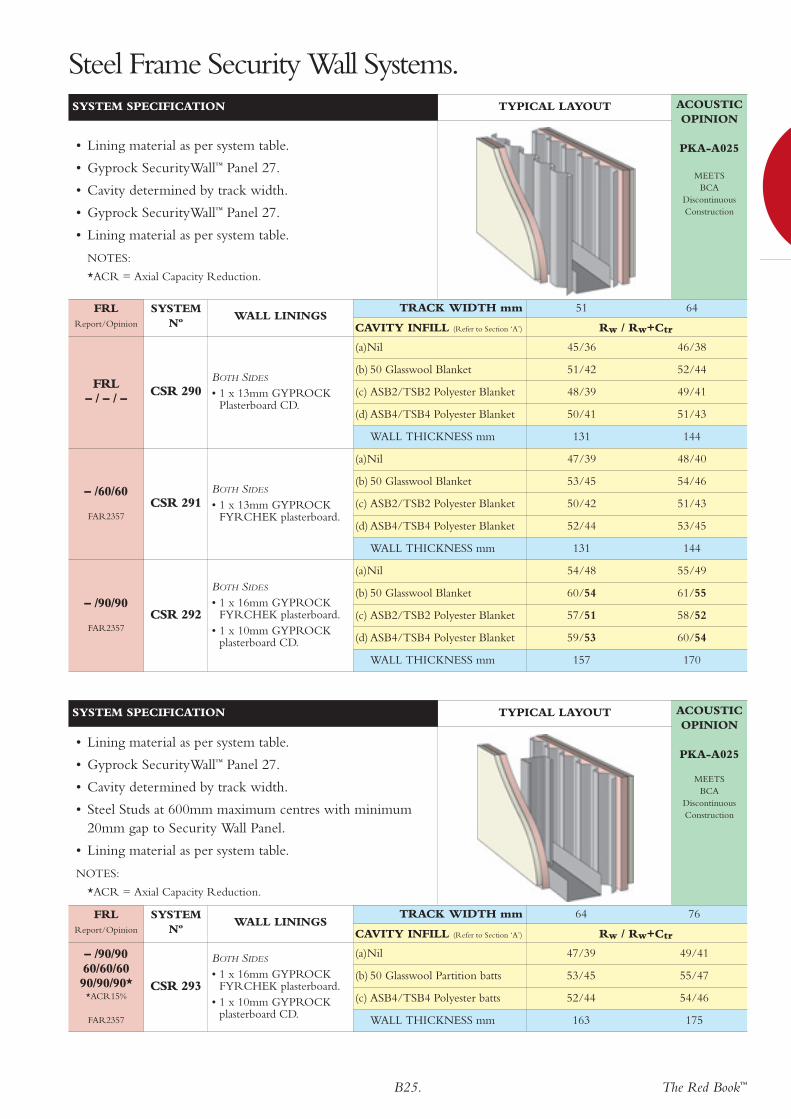
– /90/90
FAR2357
(a)Nil 54/48 55/49
(b) 50 Glasswool Blanket 60/54 61/55
(c) ASB2/TSB2 Polyester Blanket 57/51 58/52
(d) ASB4/TSB4 Polyester Blanket 59/53 60/54
WALL THICKNESS mm 157 170
CSR 292
BOTH SIDES
• 1 x 16mm GYPROCKFYRCHEK plasterboard.
• 1 x 10mm GYPROCKplasterboard CD.
– /60/60
FAR2357
(a)Nil 47/39 48/40
(b) 50 Glasswool Blanket 53/45 54/46
(c) ASB2/TSB2 Polyester Blanket 50/42 51/43
(d) ASB4/TSB4 Polyester Blanket 52/44 53/45
WALL THICKNESS mm 131 144
CSR 291BOTH SIDES
• 1 x 13mm GYPROCKFYRCHEK plasterboard.
FRL– / – / –
(a)Nil 45/36 46/38
(b) 50 Glasswool Blanket 51/42 52/44
(c) ASB2/TSB2 Polyester Blanket 48/39 49/41
(d) ASB4/TSB4 Polyester Blanket 50/41 51/43
WALL THICKNESS mm 131 144
CSR 290BOTH SIDES
• 1 x 13mm GYPROCKPlasterboard CD.
ACOUSTICOPINION
PKA-A025
MEETSBCA
DiscontinuousConstruction
FRLReport/Opinion
SYSTEM Nº
WALL LININGS
SYSTEM SPECIFICATION TYPICAL LAYOUT
• Lining material as per system table.
• Gyprock SecurityWall™ Panel 27.
• Cavity determined by track width.
• Gyprock SecurityWall™ Panel 27.
• Lining material as per system table.
NOTES:
*ACR = Axial Capacity Reduction.
TRACK WIDTH mm 51 64
CAVITY INFILL (Refer to Section ‘A’) Rw / Rw+Ctr
Steel Frame Security Wall Systems.
– /90/9060/60/6090/90/90*
*ACR15%
FAR2357
(a)Nil 47/39 49/41
(b) 50 Glasswool Partition batts 53/45 55/47
(c) ASB4/TSB4 Polyester batts 52/44 54/46
WALL THICKNESS mm 163 175
CSR 293
BOTH SIDES
• 1 x 16mm GYPROCKFYRCHEK plasterboard.
• 1 x 10mm GYPROCKplasterboard CD.
ACOUSTICOPINION
PKA-A025
MEETSBCA
DiscontinuousConstruction
FRLReport/Opinion
SYSTEM Nº
WALL LININGS
SYSTEM SPECIFICATION TYPICAL LAYOUT
• Lining material as per system table.
• Gyprock SecurityWall™ Panel 27.
• Cavity determined by track width.
• Steel Studs at 600mm maximum centres with minimum20mm gap to Security Wall Panel.
• Lining material as per system table.
NOTES:
*ACR = Axial Capacity Reduction.
TRACK WIDTH mm 64 76
CAVITY INFILL (Refer to Section ‘A’) Rw / Rw+Ctr

– /90/90
FAR2357
(a)Nil 48/42 49/43 50/44
(b) 50 Glasswool Blanket 54/48^ 55/49 56/50
(c) ASB2/TSB2 Polyester Blanket 51/45^ 52/46 53/47
(d) ASB4/TSB4 Polyester Blanket – – 55/49^
(e) 75 Glasswool Blanket – 56/50^ 57/51^
WALL THICKNESS mm 160 183 196
CSR 297BOTH SIDES
• 1 x 16mm GYPROCKFYRCHEK plasterboard.
– /90/90
FAR2357
(a)Nil 50/44 52/46 53/47
(b) 50 Glasswool Blanket 56/50^ 58/52 59/53
(c) ASB2/TSB2 Polyester Blanket 53/47^ 55/49 56/50
(d) ASB4/TSB4 Polyester Blanket – – 58/52^
(e) 75 Glasswool Blanket – 59/53^ 60/54^
WALL THICKNESS mm 180 203 216
CSR 295
BOTH SIDES
• 1 x 16mm GYPROCKFYRCHEK plasterboard.
• 1 x 10mm GYPROCKplasterboard CD.
B26. The Red Book™
– /60/60
FAR2357
(a)Nil 46/40 48/42 49/43
(b) 50 Glasswool Blanket 52/46^ 54/48 55/49
(c) ASB2/TSB2 Polyester Blanket 51/45^ 51/47 54/48
(d) ASB4/TSB4 Polyester Blanket – – 56/50^
(e) 75 Glasswool Blanket – 55/49^ 56/50^
WALL THICKNESS mm 154 177 190
CSR 294BOTH SIDES
• 1 x 13mm GYPROCKFYRCHEK plasterboard.
ACOUSTICOPINION
PKA-A025
MEETSBCA
DiscontinuousConstruction
SYSTEM SPECIFICATION TYPICAL LAYOUT
• Lining material as per system table.
• Gyprock SecurityWall™ Panel 50.
• Cavity determined by track width.
• Gyprock SecurityWall™ Panel 50.
• Lining material as per system table.
Steel Frame Security Wall Systems.
FRLReport/Opinion
SYSTEM Nº
WALL LININGSTRACK WIDTH mm 28 51 64
CAVITY INFILL (Refer to Section ‘A’) Rw / Rw+Ctr
Steel Frame Security Wall Systems.
NOTES:
^SecurityWall Panel ribs offset to enable insulation to fit.

The Red Book™B27.
Steel Frame Security Wall Systems.Steel Frame Security Wall Systems.
– /90/9060/60/6090/90/90*
*ACR15%
FAR2357
(a)Nil 50/43 51/44 51/44
(b) 75 Glasswool Blanket 57/50 58/51 58/51
(c) ASB4/TSB4 Polyester Blanket 55/48 56/49 56/49
WALL THICKNESS mm 166 178 194
CSR 298BOTH SIDES
• 1 x 16mm GYPROCKFYRCHEK plasterboard.
– /90/9060/60/6090/90/90*
*ACR15%
FAR2357
(a)Nil 50/43 51/44 52/45
(b) 75 Glasswool Blanket 57/50 58/51 59/52
(c) ASB4/TSB4 Polyester Blanket 55/48 56/49 57/50
WALL THICKNESS mm 186 198 214
CSR 296
BOTH SIDES
• 1 x 16mm GYPROCKFYRCHEK plasterboard.
• 1 x 10mm GYPROCKplasterboard CD.
ACOUSTICOPINION
PKA-A025
MEETSBCA
DiscontinuousConstruction
FRLReport/Opinion
SYSTEM Nº
WALL LININGS
SYSTEM SPECIFICATION TYPICAL LAYOUT
• Lining material as per system table.
• Gyprock SecurityWall™ Panel 50.
• Cavity determined by track width.
• Steel Studs at 600mm maximum centres with minimum20mm gap to Security Wall Panel.
• Lining material as per system table.
TRACK WIDTH mm 64 76 92
CAVITY INFILL (Refer to Section ‘A’) Rw / Rw+Ctr

B28. The Red Book™
120/120/120 (from outside only)
FAR2357
1200CSR 942
EXTERNAL SIDE
• 3 x 16mm GYPROCKFYRCHEK MRplasterboard
90/90/90 (from outside only)
FAR2357
900CSR 941
EXTERNAL SIDE
• 3 x 13mm GYPROCKFYRCHEK MRplasterboard
60/60/60(from outside only)
FAR2357
600CSR 940
EXTERNAL SIDE
• 2 x 16mm GYPROCKFYRCHEK MRplasterboard
ACOUSTICOPINION
PKA-A025
FRLReport/Opinion
SYSTEM Nº
WALL LININGS
SYSTEM SPECIFICATION TYPICAL LAYOUT
• Structural steel girts to engineer’s detail. Maximumspacing as per system table.
• GYPROCK FYRCHEK MR plasterboard, as per systemtable.
• Vapour barrier
• Galvanised steel battens fixed through plasterboard to steelgirts.
• External cladding.
MAXIMUM GIRT SPACING(MM)
CAVITY INFILL(Refer to Section ‘A’)
Rw
Steel Frame ExternalWall Systems.
60/60/60(from outside only)
FAR2357
(a) Nil 40940 +
ExpressWall
EXTERNAL SIDE
• 2 x 16mm GYPROCKFYRCHEK MR plasterboard.
ACOUSTICOPINION
PKA-A025
FRLReport/Opinion
SYSTEM Nº
WALL LININGS
SYSTEM SPECIFICATION TYPICAL LAYOUT
• Structural steel girts to engineer’s detail (600mm max.centres).
• GYPROCK FYRCHEK MR plasterboard, as per systemtable.
• CSR ExpressWall™ top hat framing system as detailed inbrochure Nº FC126,
• CSR ExpressWall™ Facade System.
CAVITY INFILL Rw
(a)Nil 33
(a)Nil 35
(a)Nil 36

The Red Book™B29.
60/60/60(from outside only)
FAR2357
(a) Nil 44
(b) 75 Comfortseal™ R1.5 batts 51
(c) 75 Soundscreen™ R2.0 RW 51
WALL THICKNESS mm 113
CSR 128INTERNAL WALL SIDE
• 1 x 16mm GYPROCKFYRCHEK plasterboard.
60/60/60(from outside only)
FAR2357
(a) Nil 43
(b) 75 Comfortseal™ R1.5 batts 50
(c) 75 Soundscreen™ R2.0 RW 50
WALL THICKNESS mm 107
CSR 127INTERNAL WALL SIDE
• 1 x 10mm GYPROCKPlasterboard CD.
60/60/60
FAR2357
(a) Nil 38-42
(b) 75 Comfortseal™ R1.5 batts 41-45
(c) 75 Soundscreen™ R2.0 RW 42-46
TYPICAL WALL THICKNESS mm 138
CSR 122INTERNAL WALL SIDE
• 1 x 16mm GYPROCKFYRCHEK plasterboard.
60/60/60*(from outside only)
*ACR5%FAR2357
(a) Nil 36-40
(b) 75 Comfortseal™ R1.5 batts 39-43
(c) 75 Soundscreen™ R2.0 RW 40-44
TYPICAL WALL THICKNESS mm 132
CSR 121INTERNAL WALL SIDE
• 1 x 10mm GYPROCKPlasterboard CD.
ACOUSTICOPINION
PKA-A025
FRLReport/Opinion
SYSTEM Nº
WALL LININGS
SYSTEM SPECIFICATION TYPICAL LAYOUT
• External cladding material on timber or steel battens.
• Vapour barrier.
• 1 x 16mm GYPROCK FYRCHEK MR plasterboard
• Steel studs at 600mm maximum centres.
• Lining material as per system table.
NOTES:
Acoustic performance valid for studs of 0.50 to 0.80 BMT.
*ACR = Axial Capacity Reduction.
STUD DEPTH mm 76mm
CAVITY INFILL (Refer to Section ‘A’) Rw
Steel Frame ExternalWall Systems.
ACOUSTICOPINION
PKA-A025
FRLReport/Opinion
SYSTEM Nº
WALL LININGS
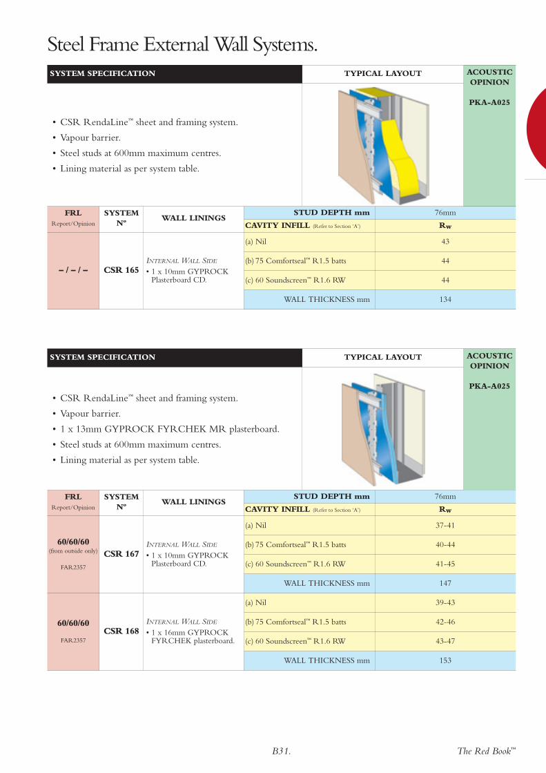
SYSTEM SPECIFICATION TYPICAL LAYOUT
• 1 x 7.5mm CSR Fibre Cement Texture Base Sheet.
• Vapour barrier.
• 1 x 13mm GYPROCK FYRCHEK MR plasterboard
• Steel studs at 600mm maximum centres.
• Lining material as per system table.
NOTES:
Acoustic performance valid for studs of 0.50 to 0.80 BMT.
STUD DEPTH mm 76mm
CAVITY INFILL (Refer to Section ‘A’) Rw

B30. The Red Book™
FRL90/90/90
FAR2357and refer to Masonry
Manufacturer
(a) Nil 55
(b) 75 Comfortseal™ R1.5 batts 61
(c) 60 Soundscreen™ R1.6 RW 64
WALL THICKNESS mm 252
CSR 186
EXTERNAL WALL SIDE
• Masonry veneer wall withFRL 90/90/90.
INTERNAL WALL SIDE
• 2 x 13mm GYPROCKFYRCHEK plasterboard.
FRL60/60/60
FAR2357 and refer to Masonry
Manufacturer
(a) Nil 51
(b) 75 Comfortseal™ R1.5 batts 57
(c) 60 Soundscreen™ R1.6 RW 60
WALL THICKNESS mm 242
CSR 185
EXTERNAL WALL SIDE
• Masonry veneer wall withFRL 60/60/60.
INTERNAL WALL SIDE
• 1 x 16mm GYPROCKFYRCHEK plasterboard.
ACOUSTICOPINION
PKA-A025
FRLReport/Opinion
SYSTEM Nº
WALL LININGS
SYSTEM SPECIFICATION TYPICAL LAYOUT
• Fire rated masonry veneer wall.
• Steel studs at 600mm maximum centres with 40mmminimum gap to masonry.
• Lining material as per system table.
STUD DEPTH mm 76mm
CAVITY INFILL (Refer to Section ‘A’) Rw
90/90/90
FAR2357
(a) Nil 50
(b) 75 Comfortseal™ R1.5 batts 56
(c) 60 Soundscreen™ R1.6 RW 59
WALL THICKNESS mm 203
HEBELRWS
INTERNAL WALL SIDE
• 2 x 13mm GYPROCKFYRCHEK plasterboard.
60/60/60
FAR2357
(a) Nil 49
(b) 75 Comfortseal™ R1.5 batts 55
(c) 60 Soundscreen™ R1.6 RW 58
WALL THICKNESS mm 193
HEBELRWS
INTERNAL WALL SIDE
• 1 x 16mm GYPROCKFYRCHEK plasterboard.
FRLReport/Opinion
SYSTEM Nº
WALL LININGSSTUD DEPTH mm 76mm
CAVITY INFILL (Refer to Section ‘A’) Rw
Steel Frame External Wall Systems.
ACOUSTICOPINION
PKA-A025
SYSTEM SPECIFICATION TYPICAL LAYOUT
• CSR Hebel Powerpanel AAC (75mm) screw fixed tobattens.
• Steel studs at 600mm maximum centres.
• Lining material as per system table.
The Red Book™B31.
STUD DEPTH mm 76mm
CAVITY INFILL (Refer to Section ‘A’) Rw
Steel Frame External Wall Systems.ACOUSTICOPINION
PKA-A025
SYSTEM SPECIFICATION TYPICAL LAYOUT
• CSR RendaLine™ sheet and framing system.
• Vapour barrier.
• Steel studs at 600mm maximum centres.
• Lining material as per system table.
– / – / –
(a) Nil 43
(b) 75 Comfortseal™ R1.5 batts 44
(c) 60 Soundscreen™ R1.6 RW 44
WALL THICKNESS mm 134
CSR 165INTERNAL WALL SIDE
• 1 x 10mm GYPROCKPlasterboard CD.
FRLReport/Opinion
SYSTEM Nº
WALL LININGS
60/60/60
FAR2357
(a) Nil 39-43
(b) 75 Comfortseal™ R1.5 batts 42-46
(c) 60 Soundscreen™ R1.6 RW 43-47
WALL THICKNESS mm 153
CSR 168INTERNAL WALL SIDE
• 1 x 16mm GYPROCKFYRCHEK plasterboard.
60/60/60(from outside only)
FAR2357
(a) Nil 37-41
(b) 75 Comfortseal™ R1.5 batts 40-44
(c) 60 Soundscreen™ R1.6 RW 41-45
WALL THICKNESS mm 147
CSR 167INTERNAL WALL SIDE
• 1 x 10mm GYPROCKPlasterboard CD.
FRLReport/Opinion
SYSTEM Nº
WALL LININGSSTUD DEPTH mm 76mm
CAVITY INFILL (Refer to Section ‘A’) Rw
ACOUSTICOPINION
PKA-A025
SYSTEM SPECIFICATION TYPICAL LAYOUT
• CSR RendaLine™ sheet and framing system.
• Vapour barrier.
• 1 x 13mm GYPROCK FYRCHEK MR plasterboard.
• Steel studs at 600mm maximum centres.
• Lining material as per system table.
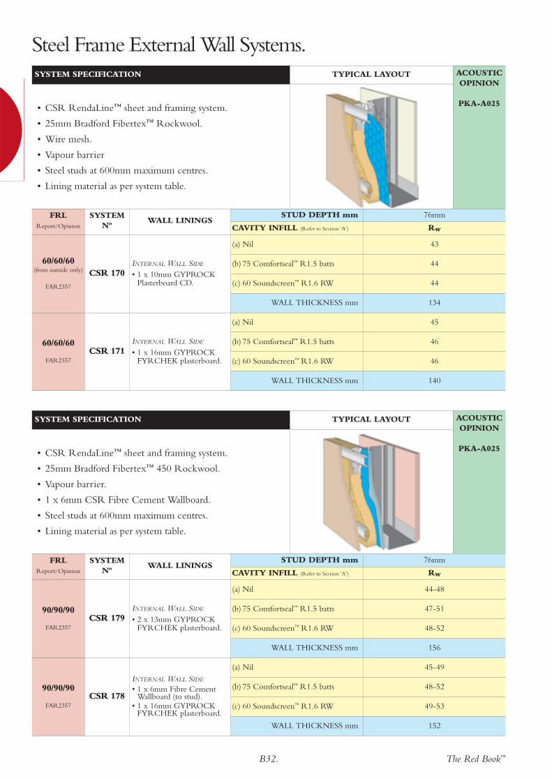
B32. The Red Book™
Steel Frame External Wall Systems.
60/60/60
FAR2357
(a) Nil 45
(b) 75 Comfortseal™ R1.5 batts 46
(c) 60 Soundscreen™ R1.6 RW 46
WALL THICKNESS mm 140
CSR 171INTERNAL WALL SIDE
• 1 x 16mm GYPROCKFYRCHEK plasterboard.
60/60/60(from outside only)
FAR2357
(a) Nil 43
(b) 75 Comfortseal™ R1.5 batts 44
(c) 60 Soundscreen™ R1.6 RW 44
WALL THICKNESS mm 134
CSR 170INTERNAL WALL SIDE
• 1 x 10mm GYPROCKPlasterboard CD.
FRLReport/Opinion
SYSTEM Nº
WALL LININGSSTUD DEPTH mm 76mm
CAVITY INFILL (Refer to Section ‘A’) Rw
ACOUSTICOPINION
PKA-A025
SYSTEM SPECIFICATION TYPICAL LAYOUT
• CSR RendaLine™ sheet and framing system.
• 25mm Bradford Fibertex™ Rockwool.
• Wire mesh.
• Vapour barrier
• Steel studs at 600mm maximum centres.
• Lining material as per system table.
90/90/90
FAR2357
(a) Nil 45-49
(b) 75 Comfortseal™ R1.5 batts 48-52
(c) 60 Soundscreen™ R1.6 RW 49-53
WALL THICKNESS mm 152
CSR 178
INTERNAL WALL SIDE
• 1 x 6mm Fibre CementWallboard (to stud).
• 1 x 16mm GYPROCKFYRCHEK plasterboard.
90/90/90
FAR2357
(a) Nil 44-48
(b) 75 Comfortseal™ R1.5 batts 47-51
(c) 60 Soundscreen™ R1.6 RW 48-52
WALL THICKNESS mm 156
CSR 179INTERNAL WALL SIDE
• 2 x 13mm GYPROCKFYRCHEK plasterboard.
FRLReport/Opinion
SYSTEM Nº
WALL LININGSSTUD DEPTH mm 76mm
CAVITY INFILL (Refer to Section ‘A’) Rw
ACOUSTICOPINION
PKA-A025
SYSTEM SPECIFICATION TYPICAL LAYOUT
• CSR RendaLine™ sheet and framing system.
• 25mm Bradford Fibertex™ 450 Rockwool.
• Vapour barrier.
• 1 x 6mm CSR Fibre Cement Wallboard.
• Steel studs at 600mm maximum centres.
• Lining material as per system table.

The Red Book™B33.
– /120/120
FCO 1786(a) Nil 37
CSR969SA
EXTERNAL SIDE
• 1 x 16mm GYPROCKFYRCHEK plasterboard.
• 1 x 25mm GYPROCKSHAFT LINER PANEL.
• 1 x 16mm GYPROCKFYRCHEK plasterboard(screw & adhesive fixing).
– /120/120
FCO 1786(a) Nil 36
CSR968SA
EXTERNAL SIDE
• 3 x 16mm GYPROCKFYRCHEK plasterboard(screw & adhesive fixing).
– /120/120
FCO 1786(a) Nil 36
CSR968S
EXTERNAL SIDE
• 3 x 16mm GYPROCKFYRCHEK plasterboard(screw fixing).
– /90/90
FCO 1786(a) Nil 35
CSR967SA
EXTERNAL SIDE
• 3 x 13mm GYPROCKFYRCHEK plasterboard(screw & adhesive fixing).
– /90/90
FCO 1786(a) Nil 35
CSR967S
EXTERNAL SIDE
• 3 x 13mm GYPROCKFYRCHEK plasterboard(screw fixing).
ACOUSTICOPINION
PKA-A025
FRLReport/Opinion
SYSTEM Nº
WALL LININGS
SYSTEM SPECIFICATION TYPICAL LAYOUT
• Perimeter framing 25/50 x 50 x 0.8 BMT steel angle.
• 3 x GYPROCK FYRCHEK/SHAFT LINER PANELlaminated with screws (S), or screws and adhesive (SA).
CAVITY INFILL (Refer to Section ‘A’) Rw
Steel Frame LaminatedServices Systems.

B34. The Red Book™
120/120/120
FAR2357
(a) 2 x Tontine Acoustisorb-1 81
(b) 2 x 110 Bradford Glasswool Building Blanket 81
(c) 2 x Autex AAB32-100 81
MINIMUM WALL THICKNESS mm 503
CSR 947BOTH SIDES
• 4 x 16mm GYPROCKFYRCHEK plasterboard
120/120/120
FAR2357
(a) 2 x Tontine Acoustisorb-1 79
(b) 2 x 110 Bradford Glasswool Building Blanket 79
(c) 2 x Autex AAB32-100 79
MINIMUM WALL THICKNESS mm 487
CSR 946
SIDE ONE
• 3 x 16mm GYPROCKFYRCHEK plasterboard
SIDE TWO
• 4 x 16mm GYPROCKFYRCHEK plasterboard
120/120/120
FAR2357
(a) 2 x Tontine Acoustisorb-1 77
(b) 2 x 110 Bradford Glasswool Building Blanket 77
(c) 2 x Autex AAB32-100 77
MINIMUM WALL THICKNESS mm 471
CSR 945BOTH SIDES
• 3 x 16mm GYPROCKFYRCHEK plasterboard
ACOUSTICOPINION
PKA-A025
FRLReport/Opinion
SYSTEM Nº
WALL LININGS
SYSTEM SPECIFICATION TYPICAL LAYOUT
• Lining material as per system table.
• Steel columns, to engineer’s design.
• Girts fixed to columns with GYPROCK CINEMAWALL MOUNTS.
• Top hat sections at 900mm maximum centres toengineer’s design.
• 2 x layers glasswool or polyester insulation. Refer toinsulation specification.
• Lining material as per system table.
CAVITY INFILL (Refer to Section ‘A’) Rw
Steel Frame CinemaWall Systems.
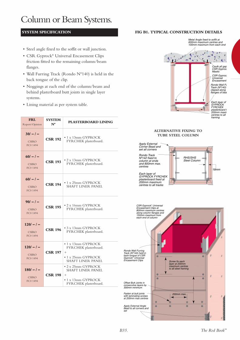
The Red Book™B35.
Column or Beam Systems.
30/ – / –
CSIROFC0 1494
CSR 192 • 1 x 13mm GYPROCKFYRCHEK plasterboard.
60/ – / –
CSIROFC0 1494
CSR 193 • 2 x 13mm GYPROCKFYRCHEK plasterboard.
60/ – / –
CSIROFC0 1494
CSR 194 • 1 x 25mm GYPROCK SHAFT LINER PANEL
90/ – / –
CSIROFC0 1494
CSR 195 • 2 x 16mm GYPROCKFYRCHEK plasterboard.
120/ – / –
CSIROFC0 1494
CSR 196 • 3 x 13mm GYPROCKFYRCHEK plasterboard.
120/ – / –
CSIROFC0 1494
CSR 197
• 1 x 13mm GYPROCKFYRCHEK plasterboard.
+• 1 x 25mm GYPROCK
SHAFT LINER PANEL
180/ – / –
CSIROFC0 1494
CSR 198
• 2 x 25mm GYPROCK SHAFT LINER PANEL
+• 1 x 13mm GYPROCK
FYRCHEK plasterboard.
SYSTEM SPECIFICATION FIG B1. TYPICAL CONSTRUCTION DETAILS
• Steel angle fixed to the soffit or wall junction.
• CSR Gyprock® Universal Encasement Clipsfriction fitted to the remaining column/beamflanges.
• Wall Furring Track (Rondo Nº140) is held in theback tongue of the clip.
• Noggings at each end of the column/beam andbehind plasterboard butt joints in single layersystems.
• Lining material as per system table.
CSR GyprockUniversal Encasement
Caulk all gapCSR GyprockMastic
Metal Angle fixed to soffit at 600mm maximum centres and 100mm maximum from each end
Rondo Wall FuTrack (Nº140) clipped along flanges of bea
Each layer of GYPROCK FYRCHEK plasterboard f200mm maximcentres to all framing
FRLReport/Opinion
SYSTEM Nº
PLASTERBOARD LINING
Rondo Track Nº142 fixed to column at ends and 800mm max. centres
Apply External Corner Bead and set all corners
Each layer of GYPROCK FYRCHEK plasterboard fixed at 200mm maximum centres to all tracks
RHS/SHSSteel Column
18mm
ALTERNATIVE FIXING TO TUBE STEEL COLUMN
Screw fix each layer at 200mm maximum centres to all steel framing
CSR Gyprock ® Universal Encasement Clips at 800mm maximum centres along column flanges and 150mm maximum from each end of column
Rondo Wall Furring Track (Nº140) held in back tongue of CSR Gyprock ® Universal Encasement Clips
Apply External Angle Bead to all corners and set
Offset Butt Joints in consecutive layers by 300mm minimum
Fasten at butt joints with laminating screws at 200mm max centres
200mm max.
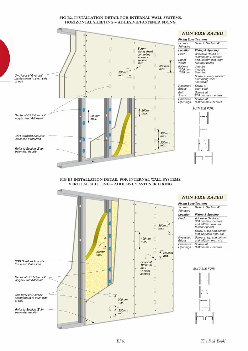
B36. The Red Book™
One layer of Gyprock® plasterboard to each side of wall
200mmmin.
200mmmin.
300mmmax.
300mm max.
300mm max.
400mm max.
Daubs of CSR Gyprock®
Acrylic Stud Adhesive
Screw at 1200mm max. vertical centres
Refer to Section ‘Z’ for perimeter details
CSR Bradford Acoustic Insulation if required
FIG B3 INSTALLATION DETAIL FOR INTERNAL WALL SYSTEMS. VERTICAL SHEETING – ADHESIVE/FASTENER FIXING.
Fixing & SpacingAdhesive Daubs at300mm max. centresand 200mm min. fromfastener pointsScrew at top and bottomand 1200mm max. ctsScrew at top and bottomand 400mm max. ctsScrews at 300mm max. centres
LocationField
RecessedEdgesCorners &Openings
Fixing SpecificationsScrews Refer to Section ‘A’Adhesive
SUITABLE FOR:
300mmmax.
200mm min.
200mm min.
300mm max.
200mmmax.
300mm max.
One layer of Gyprock® plasterboard to each side of wall
Daubs of CSR Gyprock®
Acrylic Stud Adhesive
Refer to Section ‘Z’ for perimeter details
CSR Bradford Acoustic Insulation if required
Screw along sheet centreline at every second stud
FIG B2. INSTALLATION DETAIL FOR INTERNAL WALL SYSTEMS. HORIZONTAL SHEETING – ADHESIVE/FASTENER FIXING.
Fixing & SpacingAdhesive Daubs at300mm max. centresand 200mm min. fromfastener points3 daubs4 daubs5 daubsScrew at every secondstud along sheetcentrelineScrew at each studScrews at 200mm max. centresScrews at 300mm max. centres
LocationField
Sheet Width900mm1200mm1350mm
RecessedEdgesButtJointsCorners &Openings
Fixing SpecificationsScrews Refer to Section ‘A’Adhesive
SUITABLE FOR:
NON FIRE RATED
NON FIRE RATED

The Red Book™B37.
300mmmax.
200mmmax.
300mmmax.
400mmmax.
400mmmax.
400mmmax.
Two layers of Gyprock® plasterboard to each side of wall
Daubs of CSR Gyprock®
Acrylic Stud Adhesive
Refer to Section ‘Z’ for perimeter details
CSR Bradford Acoustic Insulation if required
200mmmin.
Screw at 1200mm max. vertical centres
FIG B4. INSTALLATION DETAIL FOR INTERNAL WALL SYSTEMS. VERTICAL SHEETING – ADHESIVE/FASTENER FIXING.
Fixing & SpacingScrews at top andbottom and at 400mmmax. centres
1st Layer RecessedEdges &Field
Fixing & SpacingAdhesive Daubs at300mm max. centresand 200mm min. fromfastener pointsScrew at top and bottomand 1200mm max.ctsScrew at top and bottomand 400mm max. ctsScrews at 300mm max. centres
2nd LayerField
RecessedEdgesCorners &Openings
Fixing SpecificationsScrews Refer to Section ‘A’Adhesive
SUITABLE FOR:
300mmmax.
300mmmax.
300mmmax.One layer of GYPROCK
FYRCHEK plasterboard to each side of wall in accordance with system specifications
Refer to Section ‘Z’ for perimeter details
CSR Bradford Acoustic Insulation if required
FIG B5. INSTALLATION DETAIL FOR INTERNAL WALL SYSTEMS. SINGLE LAYER – VERTICAL SHEETING.
Fixing & SpacingScrews at 300mm max.centresScrews at 300mm max. centresScrews at 200mm max. centresScrews at 300mm max. centres
LocationField
RecessedEdgesButtJointsCorners &Openings
Fixing SpecificationsScrews Refer to Section ‘A’
SUITABLE FOR:
NON FIRE RATED
FIRE RATED
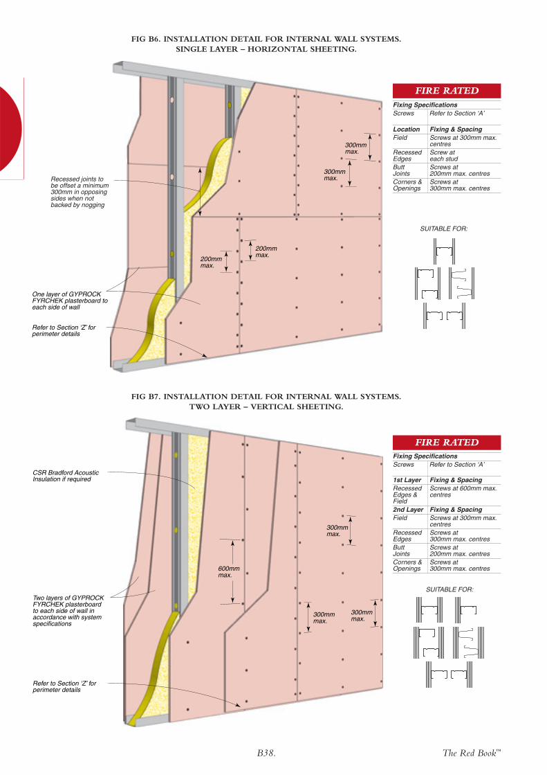
B38. The Red Book™
300mmmax.
300mmmax.
200mmmax.
200mmmax.
One layer of GYPROCK FYRCHEK plasterboard to each side of wall
Refer to Section ‘Z’ for perimeter details
Recessed joints to be offset a minimum 300mm in opposing sides when not backed by nogging
FIG B6. INSTALLATION DETAIL FOR INTERNAL WALL SYSTEMS. SINGLE LAYER – HORIZONTAL SHEETING.
Fixing & SpacingScrews at 300mm max.centresScrew at each studScrews at 200mm max. centresScrews at 300mm max. centres
LocationField
RecessedEdgesButtJointsCorners &Openings
Fixing SpecificationsScrews Refer to Section ‘A’
300mmmax.
300mmmax.
600mmmax.
300mmmax.
Two layers of GYPROCK FYRCHEK plasterboard to each side of wall in accordance with system specifications
Refer to Section ‘Z’ for perimeter details
CSR Bradford Acoustic Insulation if required
FIG B7. INSTALLATION DETAIL FOR INTERNAL WALL SYSTEMS. TWO LAYER – VERTICAL SHEETING.
Fixing & SpacingScrews at 600mm max.centres
1st Layer RecessedEdges &Field
Fixing & SpacingScrews at 300mm max.centresScrews at 300mm max. centresScrews at 200mm max. centresScrews at 300mm max. centres
2nd LayerField
RecessedEdgesButtJointsCorners &Openings
Fixing SpecificationsScrews Refer to Section ‘A’
SUITABLE FOR:
FIRE RATED
FIRE RATED
SUITABLE FOR:
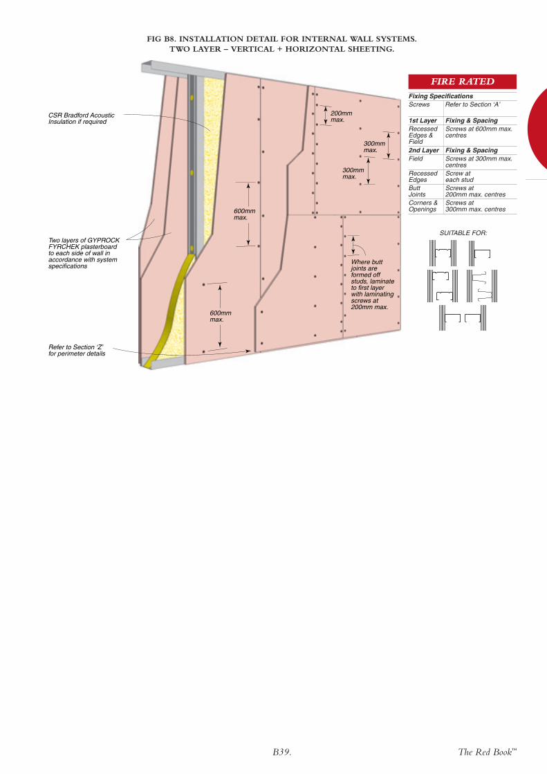
The Red Book™B39.
600mmmax.
600mmmax.
Two layers of GYPROCK FYRCHEK plasterboard to each side of wall in accordance with system specifications
Refer to Section ‘Z’ for perimeter details
CSR Bradford Acoustic Insulation if required
300mmmax.
300mmmax.
200mmmax.
Where butt joints are formed off studs, laminate to first layer with laminating screws at 200mm max.
FIG B8. INSTALLATION DETAIL FOR INTERNAL WALL SYSTEMS. TWO LAYER – VERTICAL + HORIZONTAL SHEETING.
Fixing & SpacingScrews at 600mm max.centres
1st Layer RecessedEdges &Field
Fixing & SpacingScrews at 300mm max.centresScrew at each studScrews at 200mm max. centresScrews at 300mm max. centres
2nd LayerField
RecessedEdgesButtJointsCorners &Openings
Fixing SpecificationsScrews Refer to Section ‘A’
FIRE RATED
SUITABLE FOR:

B40. The Red Book™
Offset all joints 300mm min. from previous layer
600mm600mm
300mm 300mm
400mm
400mm
400mm
Refer to Section ‘Z’ for perimeter details
FIG B9. INSTALLATION DETAIL FOR INTERNAL WALL SYSTEMS. THREE LAYER – VERTICAL OR HORIZONTAL SHEETING.
SUITABLE FOR:
FIRE RATED
Fixing & SpacingScrews at 600mm max.centres on studs
Fixing & SpacingScrews at 300mm max.centres on studs
Laminating Screws at200mm max. centresScrews at 300mm max.centresFixing & SpacingLaminating screws at400x400mm max. grid
1st Layer RecessedEdges,Field,Corners &Openings2nd LayerRecessedEdgesFieldButt Joints
Corners &Openings3rd LayerRecessedEdges,Field, ButtJointsCorners &Openings
Fixing Specifications forVertical Sheeting (shown)Screws Refer to Section ‘A’
FIRE RATED
Fixing & SpacingScrews at 600mm max.centres on studs
Fixing & SpacingScrews at 600mm max.centres on studsScrews at 300mm max.centres on studsScrews at 300mm max.centresScrews at 200mm max.centres on studsFixing & SpacingLaminating screws at400x400mm max. grid
1st Layer RecessedEdges,Field, Butt Joints,Corners &Openings2nd LayerRecessedEdgesField
Corners &OpeningsButt Joints
3rd LayerRecessedEdges,Field, ButtJointsCorners &Openings
Fixing Specifications forHorizontal SheetingScrews Refer to Section ‘A’

The Red Book™B41.
35 x 35 x 0.8mm angle screw fixed at 400mm centres to each stud
Nogging as required
First layer
Fix first side as for second side
Refer to Section ‘Z’ for perimeter details
Set 3rd layer joints from accessible side
Set Joints in at least one layer
Offset all joints 300mm min. from previous layer
600mm600mm
300mm 300mm
400mm
400mm400mm
FIG B10. INSTALLATION DETAIL FOR INTERNAL WALL SYSTEMS. TWO OR THREE LAYER – VERTICAL OR HORIZONTAL SHEETING.
SUITABLE FOR:
Alternative stud type for in-line stud framing
FIRE RATED
Fixing & SpacingScrews at 600mm max.centres on studs
Fixing & SpacingScrews at 300mm max.centres on studs
Laminating Screws at200mm max. centresScrews at 300mm max.centresFixing & SpacingLaminating screws at400x400mm max. grid
1st Layer RecessedEdges,Field,Corners &Openings2nd LayerRecessedEdgesFieldButt Joints
Corners &Openings3rd LayerRecessedEdges,Field, ButtJointsCorners &Openings
Fixing Specifications forVertical Sheeting (shown)Screws Refer to Section ‘A’
FIRE RATED
Fixing & SpacingScrews at 600mm max.centres on studs
Fixing & SpacingScrews at 600mm max.centres on studsScrews at 300mm max.centres on studsScrews at 300mm max.centresScrews at 200mm max.centres on studsFixing & SpacingLaminating screws at400x400mm max. grid
1st Layer RecessedEdges,Field, Butt Joints,Corners &Openings2nd LayerRecessedEdgesField
Corners &OpeningsButt Joints
3rd LayerRecessedEdges,Field, ButtJointsCorners &Openings
Fixing Specifications forHorizontal SheetingScrews Refer to Section ‘A’
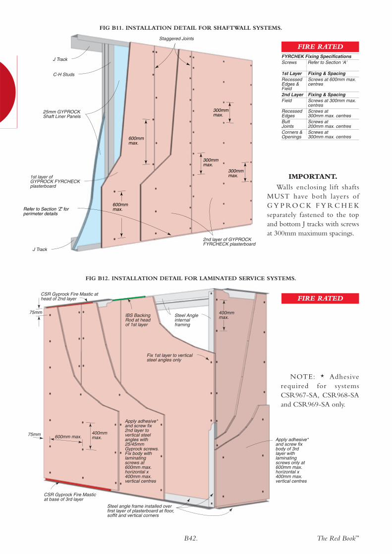
B42. The Red Book™
Steel Angle internal framing
Steel angle frame installed over first layer of plasterboard at floor, soffit and vertical corners
Fix 1st layer to vertical steel angles only
Apply adhesive* and screw fix 2nd layer to vertical steel angles with 25/45mm Gyprock screws. Fix body with laminating screws at 600mm max. horizontal x 400mm max. vertical centres
Apply adhesive* and screw fix body of 3rd layer with laminating screws only at 600mm max. horizontal x 400mm max. vertical centres
75mm 600mm max.400mmmax.
400mmmax.
75mm
CSR Gyprock Fire Mastic at head of 2nd layer
CSR Gyprock Fire Mastic at base of 3rd layer
IBS Backing Rod at head of 1st layer
FIG B12. INSTALLATION DETAIL FOR LAMINATED SERVICE SYSTEMS.
NOTE: * Adhesiverequired for systemsCSR967-SA, CSR968-SAand CSR969-SA only.
J Track
C-H Studs
Staggered Joints
25mm GYPROCKShaft Liner Panels
J Track
2nd layer of GYPROCK FYRCHECK plasterboard
1st layer ofGYPROCK FYRCHECKplasterboard
Refer to Section ‘Z’ for perimeter details
300mmmax.
300mmmax.
600mmmax.
600mmmax.
300mmmax.
Fixing & SpacingScrews at 600mm max.centres
1st Layer RecessedEdges &Field
Fixing & SpacingScrews at 300mm max.centresScrews at 300mm max. centresScrews at 200mm max. centresScrews at 300mm max. centres
2nd LayerField
RecessedEdgesButtJointsCorners &Openings
FYRCHEK Fixing SpecificationsScrews Refer to Section ‘A’
FIRE RATED
FIRE RATED
FIG B11. INSTALLATION DETAIL FOR SHAFTWALL SYSTEMS.
IMPORTANT.
Walls enclosing lift shaftsMUST have both layers ofG Y P RO C K F Y R C H E Kseparately fastened to the topand bottom J tracks with screwsat 300mm maximum spacings.
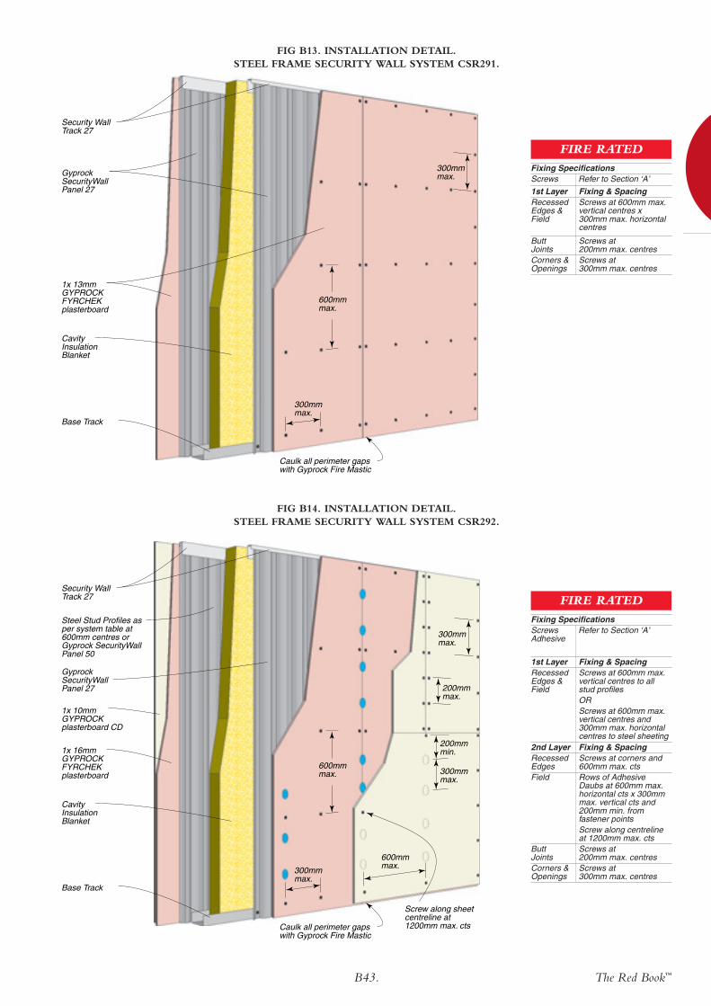
The Red Book™B43.
Security Wall Track 27
1x 10mm GYPROCK plasterboard CD
1x 16mm GYPROCK FYRCHEK plasterboard
Cavity Insulation Blanket
Gyprock SecurityWall Panel 27
Base Track
200mmmin.
600mmmax.
200mmmax.
300mmmax.
300mmmax.
600mmmax.300mm
max.
Screw along sheet centreline at 1200mm max. cts Caulk all perimeter gaps
with Gyprock Fire Mastic
Steel Stud Profiles as per system table at 600mm centres or Gyprock SecurityWall Panel 50
FIG B14. INSTALLATION DETAIL.STEEL FRAME SECURITY WALL SYSTEM CSR292.
Fixing & SpacingScrews at 600mm max.vertical centres x300mm max. horizontalcentres
1st Layer RecessedEdges &Field
Screws at 200mm max. centresScrews at 300mm max. centres
ButtJointsCorners &Openings
Fixing SpecificationsScrews Refer to Section ‘A’
FIRE RATED
FIG B13. INSTALLATION DETAIL.STEEL FRAME SECURITY WALL SYSTEM CSR291.
Fixing SpecificationsScrews Refer to Section ‘A’Adhesive
Fixing & SpacingScrews at 600mm max.vertical centres to allstud profiles ORScrews at 600mm max.vertical centres and300mm max. horizontalcentres to steel sheeting
1st Layer RecessedEdges &Field
Fixing & SpacingScrews at corners and600mm max. ctsRows of AdhesiveDaubs at 600mm max.horizontal cts x 300mmmax. vertical cts and200mm min. fromfastener pointsScrew along centrelineat 1200mm max. ctsScrews at 200mm max. centresScrews at 300mm max. centres
2nd LayerRecessedEdgesField
ButtJointsCorners &Openings
FIRE RATED
Security Wall Track 27
1x 13mm GYPROCK FYRCHEK plasterboard
Cavity Insulation Blanket
Gyprock SecurityWall Panel 27
Base Track
600mmmax.
300mmmax.
300mmmax.
Caulk all perimeter gaps with Gyprock Fire Mastic

B44. The Red Book™
Fixing & SpacingScrews at 600mm max.vertical centres to allstud profiles ORScrews at 600mm max.vertical centres x216mm max. horizontalcentres to all steel ribs
1st Layer RecessedEdges &Field
Fixing & SpacingScrews at 433mm max.ctsRows of AdhesiveDaubs at 600mm max.horizontal cts x 300mmmax. vertical cts and200mm min. fromfastener pointsScrew along centrelineat 1300mm max.ctsScrews at 200mm max. centresScrews at 300mm max. centres
2nd LayerRecessedEdgesField
ButtJointsCorners &Openings
Fixing SpecificationsScrews Refer to Section ‘A’Adhesive
FIRE RATED
FIG B16. INSTALLATION DETAIL.STEEL FRAME SECURITY WALL SYSTEM CSR296.
FIG B15. INSTALLATION DETAIL.STEEL FRAME SECURITY WALL SYSTEM CSR294.
Fixing & SpacingScrews at 600mm max.vertical centres x216mm max. horizontalcentres to all steel ribs
1st Layer Top,Bottom &Field
Screws at 216mm max. centresScrews at 300mm max. centres
ButtJointsCorners &Openings
Fixing SpecificationsScrews Refer to Section ‘A’
FIRE RATEDSecurity Wall Track 50
1x 13mm GYPROCK FYRCHEK plasterboard
Cavity InsulationBlanket
Gyprock SecurityWall Panel 50
Base Track
600mmmax.
300mmmax.
216mmmax.
Caulk all perimeter gaps with Gyprock Fire Mastic
Security Wall Track 50
1x 10mm GYPROCK plasterboard CD
1x 16mm GYPROCK FYRCHEK plasterboard
Cavity InsulationBatts
Gyprock SecurityWall Panel 50
Head Track
Base Track
Steel Stud Profiles as per system table at 600mm centres or Gyprock SecurityWall Panel 50
200mm min.
600mmmax.
200mmmax.
300mmmax.
300mm max.
600mmmax.
433mmmax.433mm
max.
216mmmax.
Screw along sheet centreline at 1200mm max. cts Caulk all perimeter gaps
with Gyprock Fire Mastic
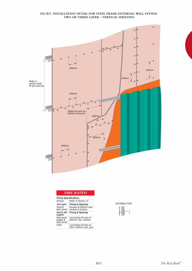
The Red Book™B45.
Refer to system table for girt spacing
200mm
200mm
200mm
400mm
Offset all joints by 300mm minimum
200mm
200mm
400mm
FIG B17. INSTALLATION DETAIL FOR STEEL FRAME EXTERNAL WALL SYSTEM. TWO OR THREE LAYER – VERTICAL SHEETING
SUITABLE FOR:Fixing & SpacingScrews at 200mm max.centres to all girts
1st Layer Field & Butt Joints
Fixing & Spacing
Laminating Screws at 200mm max. centres
Laminating Screws at 400 x 400mm max. grid
2nd & 3rdLayersRecessedEdges &Butt JointsField
Fixing SpecificationsScrews Refer to Section ‘A’
FIRE RATED
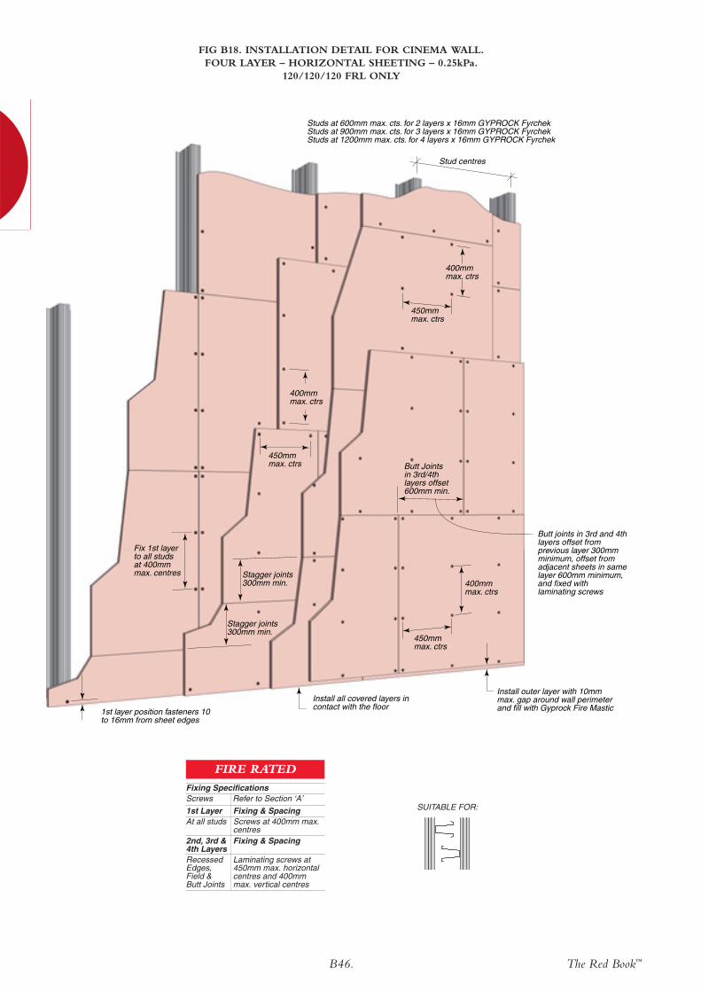
B46. The Red Book™
1st layer position fasteners 10 to 16mm from sheet edges
Stagger joints300mm min.
Stagger joints300mm min.
Fix 1st layerto all studsat 400mmmax. centres
400mmmax. ctrs
Butt Joints in 3rd/4th layers offset 600mm min.
Install all covered layers in contact with the floor
Install outer layer with 10mm max. gap around wall perimeter and fill with Gyprock Fire Mastic
450mmmax. ctrs
450mmmax. ctrs
450mmmax. ctrs
400mmmax. ctrs
400mmmax. ctrs
Butt joints in 3rd and 4th layers offset from previous layer 300mm minimum, offset from adjacent sheets in same layer 600mm minimum, and fixed with laminating screws
Studs at 600mm max. cts. for 2 layers x 16mm GYPROCK FyrchekStuds at 900mm max. cts. for 3 layers x 16mm GYPROCK FyrchekStuds at 1200mm max. cts. for 4 layers x 16mm GYPROCK Fyrchek
Stud centres
FIG B18. INSTALLATION DETAIL FOR CINEMA WALL. FOUR LAYER – HORIZONTAL SHEETING – 0.25kPa.
120/120/120 FRL ONLY
SUITABLE FOR:Fixing & SpacingScrews at 400mm max.centres
1st Layer At all studs
Fixing & Spacing
Laminating screws at 450mm max. horizontalcentres and 400mmmax. vertical centres
2nd, 3rd &4th LayersRecessedEdges,Field & Butt Joints
Fixing SpecificationsScrews Refer to Section ‘A’
FIRE RATED
Related Documents


