Concrete in Australia | Vol 44 No 1 29 TECHNICAL PAPERS 1.0 INTRODUCTION Concrete is a brittle material and has an inherent weakness in resisting in tension. Concrete cracks under low levels of tensile stress and usually fails by sudden propagation of these cracks. In order to prevent brittle failure, appropriate load carrying mechanism must be provided across the crack, such as, steel reinforcement. A similar concept is applicable for the case of steel fibre reinforced concrete (SFRC), where discontinuous fibres are added as reinforcement to bridge cracks and to transmit tensile stresses across cracks, thereby improving the ductility and the performance of the SFRC. SFRC has long been used in international pavement construction. Over the last 50 years, many residential and industrial pavements, public roads, motorways, railway track slabs and also airfield concrete pavement runways have been constructed with SFRC. In Australia, for the past 20 to 30 years, the use of SFRC for large industrial pavements has become common practice and it has seen moderate take up of this technology in track slabs and airfield concrete pavement. is paper presents an overview of the SFRC pavement design methodology using plastic analysis method and provides a guidance to practitioners on how to specify steel fibres. It also provides a brief review on the durability of steel fibre reinforced concrete. e conditions of some steel fibre reinforced concrete pavements constructed some 20 years ago in Australia are also reported herein. 2.0 STRUCTURAL THICKNESS DESIGN OF SFRC PAVEMENT 2.1 AUSTRALIA DESIGN GUIDELINES A concrete pavement must be of sufficient thickness to be able to withstand the various types of loading ranging from dynamic wheel loads that are applied to it by heavy vehicles to distributed loading from stacked materials. e objective of thickness design is to ensure satisfactory performance of the pavement under all the applied loads, by preventing the occurrence of excessive flexural, fatigue and bearing stresses. e Austroads Guide to Pavement Technology Part 2: Pavement Structural Design 1 and CCAA T48 Guide to Industrial Floors and Pavements 2 are commonly used in Australia for concrete pavement design. e design procedures are generally adopted from USA Portland Cement Association 3 method, which is in turn fundamentally based on the theoretical studies of pavement slab behaviour by Westergaard 4-8 . e Westergaard as well as Austroads and CCAA T48 thickness design approach uses the elasticity theory by assuming that the concrete section is uncracked. e design is more or less done for plain concrete. e computed maximum bending moment is compared to the maximum flexural capacity of the concrete, i.e. the cracking moment. As an example, Figure 1(a) shows a concrete pavement loaded to the point of flexural rupture. e maximum bending moment occurs at the bottom of the slab and, hence, the positive bending moment governs the design. It is important to note that when the maximum capacity is reached for positive bending moment, the negative bending moment is still far below maximum. SFRC behaves very differently as that of plain concrete. e addition of steel fibres to concrete enhance the post crack tensile strength and provides significant ductility to the concrete composite. Simply transferring design approaches for plain concrete pavement to SFRC pavement will hardly lead to success. SFRC pavement can still be designed in the same way using the Westergaard elastic analysis approach. Such an approach has been adopted by the Austroads 1 . However, this design approach under- estimates the load carrying capacity of SFRC pavements, as it does not take the ductile behaviour associated with the SFRC into account. In fact steel fibres only become active after cracking of the concrete matrix, therefore, the performance of the fibres in the concrete matrix does not play a role for the design. Strictly speaking, the use of elastic analysis design approach is not appropriate. 2.2 SFRC PAVEMENT DESIGN CONCEPT Figure 2 shows a typical relationship between load (moment or stress) and deflection of a SFRC pavement loaded to the point of flexural rupture observed in many studies including Skarendahl and Westerberg 9 , Beckett and Humphreys 10 and Falkner et al. 11 . e pavement behaves linear-elastically up to the proportional limit (F R ). is is equal to a plain concrete pavement flexural capacity where the maximum bending moment has occurred at the bottom of the slab. As the elastic limit is exceeded, crack begins to form at the bottom of the pavement. With SFRC, the fibres bridge the crack and provide post cracking strength and, hence, a bending STEEL FIBRE CONCRETE PAVEMENTS: THINNER AND MORE DURABLE TIAN SING NG BOSFA PTY LTD, AUSTRALASIA TREVOR NYAN SOE HTUT DEPARTMENT OF CIVIL ENGINEERING CURTIN UNIVERSITY, WESTERN AUSTRALIA Steel fibre reinforced concrete has been widely used for pavement construction. e conventional pavement design methodology and that of adopted by the Australian pavement design guidelines are generally based on elastic theory. e addition of steel fibres to concrete enhances the post crack tensile strength and provides significant ductility. Consequently, the use of elastic theory for designing steel fibre reinforced concrete pavement will be overly conservative and non-economical. Steel fibre reinforced concrete pavement can be designed using plastic analysis method such as yield line theory. is paper outlines the design methodology of steel fibre reinforced concrete pavement and how to specify steel fibres in order to guarantee a minimum level of quality and performance. It also provides a review on the durability of steel fibre reinforced concrete. e conditions of steel fibre reinforced concrete pavements constructed some 20 years ago in Australia are also presented herein.

Welcome message from author
This document is posted to help you gain knowledge. Please leave a comment to let me know what you think about it! Share it to your friends and learn new things together.
Transcript
Concrete in Australia | Vol 44 No 1 29PB Concrete in Australia | Vol 44 No 1
TECHNICAL PAPERS
1.0 INTRODUCTIONConcrete is a brittle material and has an inherent weakness in resisting in tension. Concrete cracks under low levels of tensile stress and usually fails by sudden propagation of these cracks. In order to prevent brittle failure, appropriate load carrying mechanism must be provided across the crack, such as, steel reinforcement. A similar concept is applicable for the case of steel fibre reinforced concrete (SFRC), where discontinuous fibres are added as reinforcement to bridge cracks and to transmit tensile stresses across cracks, thereby improving the ductility and the performance of the SFRC.
SFRC has long been used in international pavement construction. Over the last 50 years, many residential and industrial pavements, public roads, motorways, railway track slabs and also airfield concrete pavement runways have been constructed with SFRC. In Australia, for the past 20 to 30 years, the use of SFRC for large industrial pavements has become common practice and it has seen moderate take up of this technology in track slabs and airfield concrete pavement.
This paper presents an overview of the SFRC pavement design methodology using plastic analysis method and provides a guidance to practitioners on how to specify steel fibres. It also provides a brief review on the durability of steel fibre reinforced concrete. The conditions of some steel fibre reinforced concrete pavements constructed some 20 years ago in Australia are also reported herein. 2.0 STRUCTURAL THICKNESS DESIGN OF SFRC PAVEMENT
2.1 AUSTRALIA DESIGN GUIDELINESA concrete pavement must be of sufficient thickness to be able to withstand the various types of loading ranging from dynamic wheel loads that are applied to it by heavy vehicles to distributed loading from stacked materials. The objective of thickness design is to ensure satisfactory performance of the pavement under all the applied loads, by preventing the occurrence of excessive flexural, fatigue and bearing stresses. The Austroads Guide to Pavement Technology Part 2: Pavement Structural Design1 and CCAA T48 Guide to Industrial Floors and Pavements2 are commonly used in Australia for concrete pavement design. The design procedures are generally adopted from USA Portland Cement Association3 method, which is in turn
fundamentally based on the theoretical studies of pavement slab behaviour by Westergaard4-8.
The Westergaard as well as Austroads and CCAA T48 thickness design approach uses the elasticity theory by assuming that the concrete section is uncracked. The design is more or less done for plain concrete. The computed maximum bending moment is compared to the maximum flexural capacity of the concrete, i.e. the cracking moment.
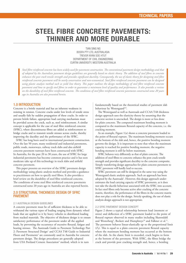
As an example, Figure 1(a) shows a concrete pavement loaded to the point of flexural rupture. The maximum bending moment occurs at the bottom of the slab and, hence, the positive bending moment governs the design. It is important to note that when the maximum capacity is reached for positive bending moment, the negative bending moment is still far below maximum.
SFRC behaves very differently as that of plain concrete. The addition of steel fibres to concrete enhance the post crack tensile strength and provides significant ductility to the concrete composite. Simply transferring design approaches for plain concrete pavement to SFRC pavement will hardly lead to success.
SFRC pavement can still be designed in the same way using the Westergaard elastic analysis approach. Such an approach has been adopted by the Austroads1. However, this design approach under-estimates the load carrying capacity of SFRC pavements, as it does not take the ductile behaviour associated with the SFRC into account. In fact steel fibres only become active after cracking of the concrete matrix, therefore, the performance of the fibres in the concrete matrix does not play a role for the design. Strictly speaking, the use of elastic analysis design approach is not appropriate.
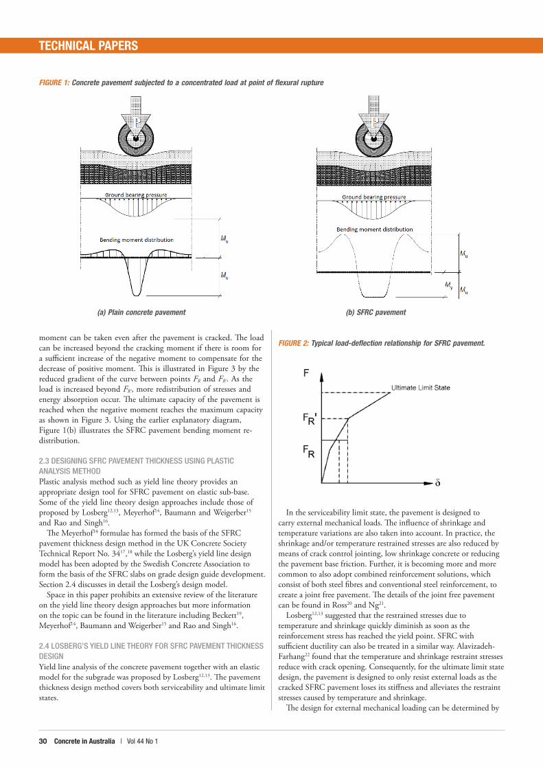
2.2 SFRC PAVEMENT DESIGN CONCEPTFigure 2 shows a typical relationship between load (moment or stress) and deflection of a SFRC pavement loaded to the point of flexural rupture observed in many studies including Skarendahl and Westerberg9, Beckett and Humphreys10 and Falkner et al.11. The pavement behaves linear-elastically up to the proportional limit (FR). This is equal to a plain concrete pavement flexural capacity where the maximum bending moment has occurred at the bottom of the slab. As the elastic limit is exceeded, crack begins to form at the bottom of the pavement. With SFRC, the fibres bridge the crack and provide post cracking strength and, hence, a bending
STEEL FIBRE CONCRETE PAVEMENTS: THINNER AND MORE DURABLE
TIAN SING NGBOSFA PTY LTD, AUSTRALASIA
TREVOR NYAN SOE HTUTDEPARTMENT OF CIVIL ENGINEERING
CURTIN UNIVERSITY, WESTERN AUSTRALIA
Steel fibre reinforced concrete has been widely used for pavement construction. The conventional pavement design methodology and that of adopted by the Australian pavement design guidelines are generally based on elastic theory. The addition of steel fibres to concrete enhances the post crack tensile strength and provides significant ductility. Consequently, the use of elastic theory for designing steel fibre reinforced concrete pavement will be overly conservative and non-economical. Steel fibre reinforced concrete pavement can be designed using plastic analysis method such as yield line theory. This paper outlines the design methodology of steel fibre reinforced concrete pavement and how to specify steel fibres in order to guarantee a minimum level of quality and performance. It also provides a review on the durability of steel fibre reinforced concrete. The conditions of steel fibre reinforced concrete pavements constructed some 20 years ago in Australia are also presented herein.
Concrete in Australia | Vol 44 No 1 3130 Concrete in Australia | Vol 44 No 1
TECHNICAL PAPERS
moment can be taken even after the pavement is cracked. The load can be increased beyond the cracking moment if there is room for a sufficient increase of the negative moment to compensate for the decrease of positive moment. This is illustrated in Figure 3 by the reduced gradient of the curve between points FR and FR'. As the load is increased beyond FR', more redistribution of stresses and energy absorption occur. The ultimate capacity of the pavement is reached when the negative moment reaches the maximum capacity as shown in Figure 3. Using the earlier explanatory diagram, Figure 1(b) illustrates the SFRC pavement bending moment re-distribution.
2.3 DESIGNING SFRC PAVEMENT THICKNESS USING PLASTIC ANALYSIS METHOD Plastic analysis method such as yield line theory provides an appropriate design tool for SFRC pavement on elastic sub-base. Some of the yield line theory design approaches include those of proposed by Losberg12,13, Meyerhof14, Baumann and Weigerber15 and Rao and Singh16.
The Meyerhof14 formulae has formed the basis of the SFRC pavement thickness design method in the UK Concrete Society Technical Report No. 3417,18 while the Losberg’s yield line design model has been adopted by the Swedish Concrete Association to form the basis of the SFRC slabs on grade design guide development. Section 2.4 discusses in detail the Losberg’s design model.
Space in this paper prohibits an extensive review of the literature on the yield line theory design approaches but more information on the topic can be found in the literature including Beckett19, Meyerhof14, Baumann and Weigerber15 and Rao and Singh16.
2.4 LOSBERG’S YIELD LINE THEORY FOR SFRC PAVEMENT THICKNESS DESIGN Yield line analysis of the concrete pavement together with an elastic model for the subgrade was proposed by Losberg12,13. The pavement thickness design method covers both serviceability and ultimate limit states.
In the serviceability limit state, the pavement is designed to carry external mechanical loads. The influence of shrinkage and temperature variations are also taken into account. In practice, the shrinkage and/or temperature restrained stresses are also reduced by means of crack control jointing, low shrinkage concrete or reducing the pavement base friction. Further, it is becoming more and more common to also adopt combined reinforcement solutions, which consist of both steel fibres and conventional steel reinforcement, to create a joint free pavement. The details of the joint free pavement can be found in Ross20 and Ng21.
Losberg12,13 suggested that the restrained stresses due to temperature and shrinkage quickly diminish as soon as the reinforcement stress has reached the yield point. SFRC with sufficient ductility can also be treated in a similar way. Alavizadeh-Farhang22 found that the temperature and shrinkage restraint stresses reduce with crack opening. Consequently, for the ultimate limit state design, the pavement is designed to only resist external loads as the cracked SFRC pavement loses its stiffness and alleviates the restraint stresses caused by temperature and shrinkage.
The design for external mechanical loading can be determined by
(a) Plain concrete pavement (b) SFRC pavement
FIGURE 2: Typical load-deflection relationship for SFRC pavement.
FIGURE 1: Concrete pavement subjected to a concentrated load at point of flexural rupture
Concrete in Australia | Vol 44 No 1 3130 Concrete in Australia | Vol 44 No 1
TECHNICAL PAPERS
assuming that the pavement is in cracked state and using the yield line theory. The following condition apply:
where Fd is the design load, g() is a function for relevant yield line pattern, while m and m' are the bending moment capacities for positive (bottom of the pavement) and negative (top of the pavement) yield lines and can be determined as:
where ffl is the SFRC design flexural strength according to Table 1 and h is the slab thickness. Solutions for g() for various loading cases can be found in Losberg12, 13.
Table 1 presents the adopted design values for the SFRC flexural strength, ffl, based on the current state of practice. In general, the post crack flexural strength of SFRC is used to carry the positive moment while the negative moment capacity is commonly determined from the flexural strength of the plain concrete or first crack flexural strength, fct,f, so as to prevent the formation of crack on top of the pavement.
Where fR,1, fR,3 and fR,4 are the residual flexural strengths at 0.5 mm, 2.5 mm and 3.5 mm crack mouth opening displacements, respectively, measured from the EN1465123 three point notched bending test.
The y() is a function for calculating the SFRC design flexural strength based on the latest or fourth edition of the UK Concrete Society Technical Report No. 3418 and has been improved from the previous of third edition of the Technical Report No. 3417. In
the previous edition of the report, the average post crack flexural strength over a net deflection of 3 mm, (fct,f × Re,3), was adopted; in some situations, the use of fct,f × Re,3 is conservative and, in other situations, unreliable, depending on the width of the pavement crack opening.
Yield line theory considers the equilibrium between the total occurring moments to the total moment capacities. Hence, by relating equation (2) and ffl values in Table 1, the overall design formula can be written as:
Ultimate limit state:
Serviceability limit state:
where MS and MT are restraining moment due to shrinkage and temperature variation, respectively.
It is important to note that when using the above equations for design, engineers have to apply the material reduction factor, fibre orientation factor and member size factor to account for the variation in SFRC strength and properties, randomness of fibre orientation and distribution in the concrete.
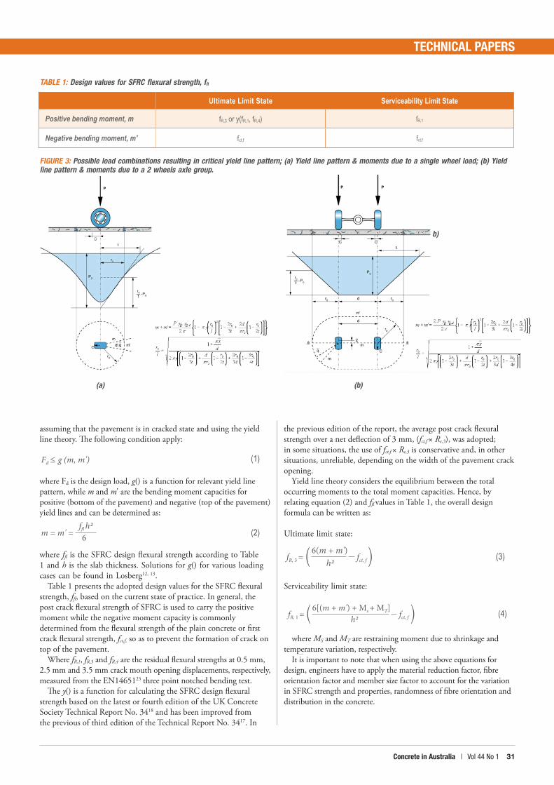
TABLE 1: Design values for SFRC flexural strength, ffl
(a) (b)
b)
FIGURE 3: Possible load combinations resulting in critical yield line pattern; (a) Yield line pattern & moments due to a single wheel load; (b) Yield line pattern & moments due to a 2 wheels axle group.
(1)Fd ≤ g (m, m')
(2)6ffl h2
m = m' =
(3)h2
fR, 3 = fct, f
6(m + m')
(4)h2fR, 1 = fct, f
6[(m + m') + Ms + MT]
Ultimate Limit State Serviceability Limit State
Positive bending moment, m fR,3 or y(fR,1, fR,4) fR,1
Negative bending moment, m' fct,f fct,f
Concrete in Australia | Vol 44 No 1 3332 Concrete in Australia | Vol 44 No 1
TECHNICAL PAPERS
2.5 EXAMPLE OF PLAIN CONCRETE AND SFRC PAVEMENT THICKNESS DESIGNA concrete pavement is to be designed to support loading from a truck with an axle load of 200 kN with a wheel spacing of 1.8m. The number of load repetitions over the design life is estimated to be 208,000. The equivalent Young’s modulus for the soil can be taken as 31.8 MPa and the concrete strength is assumed to be 40 MPa. Estimate the thickness of the pavement.
Plain Concrete Pavement Thickness Design:This design example is extracted from the CCAA2 Appendix D Example 1. Based on the guideline, the minimum pavement thickness required is 230 mm.
SFRC Pavement Thickness Design using the Losberg’s yield line theory:Step 1: Define material reduction factor and load factor
The material reduction factor for SFRC, both in compression and tension, is taken as 1/1.5 = 0.67 as per the recommendation of the fib Mode Code 201024.
The load factor is assumed to 1.2 (as opposed to 1.1 according to Table 1.16 of CCAA2).
Further, in this SFRC pavement thickness sizing, the dynamic load allowance, α, is assumed to be 40%. Effectively, the total load factor used in the design is
1.2 × (1+α) = 1.68
Step 2: Determine the critical yield line pattern:An axle load consists of 2 wheels. As it is not known beforehand
which yield line pattern is the most critical one, all possible load combinations, i.e. a single wheel load (Figure 3(a)) or an axle load, i.e. 2 wheels load (Figure 3(b)), have to be considered.
Assume initially that the SFRC pavement is 160 mm thick, Table 2 below summarises the occurring moments from the two load combinations. In this design, the 2 wheels load generates the most critical yield line pattern. Step 3: Calculate the restraint stresses due to shrinkage and temperature variation:
Take the pavement as having a saw cut at every 6 m centres, more or less similar to that of unreinforced plain concrete pavement, and having 2 layers of plastic underlays to reduce the friction of the pavement and the subbase and the temperature variation between top and bottom of the pavement section is 10 oC. The resulting moments due to shrinkage and temperature variation are 3.7 kNm/m and 2.9 kNm/m, respectively.
Step 4: Determine the required SFRC design flexural strength:The plain flexural strength of a 40 MPa concrete, fct,f, is 3.8 MPa,
determined from AS 3600.For ultimate limit state, the required SFRC design flexural
strength is determined using Equation (3):
On the other hand, the required SFRC design flexural strength for serviceability limit state design is calculated using Equation (4):
Step 5: Choose the steel fibre type, manufacturing brand and dosage:Based on the above design criteria and assumption, provide 30 kg/
m3 of a commercially available Dramix® 3D 65/60BG end hooked steel fibres where the fR,1 and fR,3 values are in excess of the required 0.6 MPa and 3.1 MPa, respectively.
Design engineers should be aware that not all fibres perform equally. The design engineer has a responsibility and duty of care to confirm that the specified steel fibre products and fibre dosage can satisfy the design properties; Section 4 below provides a guide on how to specify steel fibres.
From the above example, it is of interest to note that SFRC reduces the required pavement thickness from 230 mm to 160 mm when compared to that of plain concrete pavement. It represents 35% of reduction in pavement thickness. This design is not only a cost saving solution but it also allows faster and more efficient installation, and more sustainable by reducing the amount of concrete used. Equally important, it does not compromises the safety and quality.
As can be noted in the example, the required fR,1 value is only 0.6 MPa. Analysis shows that the pavement can be constructed as large as 50 m x 50 m panel or even larger without any joint using the same fibre and dosage. Nonetheless, the pavement size is generally being limited by the concrete supply or the ability to pour and finish the pavement in due time. Hence, by working closely with all parties involved with the project, it is possible to reduce the number of joints, increase the joint spacing and move toward large-pour jointless pavement and offer the most economical solution.
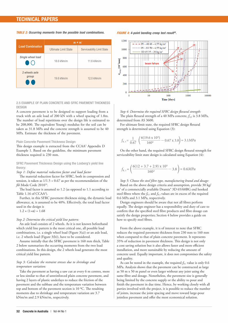
TABLE 2: Occurring moments from the possible load combinations. FIGURE 4: 4-point bending creep test result38.
Load Combinationm + m'
Ultimate Limit State Serviceability Limit State
Single wheel load18.6 kNm/m 11.6 kNm/m
2 wheels axle group
19.6 kNm/m 12.0 kNm/m
1602fR, 1 = 3.8 = 0.6MPa6(12 + 3.7 + 2.9) x 103
1fR, 3 = 0.67 x 3.80.67 1602 = 3.1MPa6(19.6 x 10³)
Concrete in Australia | Vol 44 No 1 3332 Concrete in Australia | Vol 44 No 1
TECHNICAL PAPERS
3.0 SPECIFYING STEEL FIBRES SFRC pavement design using plastic analysis method may be required to undergo significant moment redistribution and, therefore, specifying steel fibres that can guarantee a minimum level of quality and performance are critical so as to achieve a significant level of ductility.
3.1 STEEL FIBRE MATERIAL QUALITY Ensuring the steel fibres are manufactured in a quality controlled environment should be seen as a minimum requirement for any steel fibre reinforced concrete (SFRC) specification; just as AS/NZS 467125 is specified as a minimum requirement for reinforcing steel.
How to Specify:• Steel fibres should be manufactured in accordance with EN
14889-126, system 1 for structural use or, ISO 1327027 Class A.• A Declaration of Performance (DoP) should be supplied to the
project engineer or interested party and will be used to check against the CE label attached to delivered pallets of fibre.
• Fibres without a DoP and corresponding CE label attached to delivered product do not comply.
Presently, no Australian based manufacturing standard for steel fibre quality control exists. Both EN14889-1 and ISO 13270 are cited in AS 5100.528 and draft AS 3600 (DR AS 360029) as a minimum requirement for steel fibres.
3.2 STEEL FIBRE PERFORMANCE AND DOSAGEThe performance of SFRC generally increases with increasing fibre dosage. However, it is not practical, not economical and not sustainable to specify an excessive high dosage of fibre in a concrete for which the extra dosage is not structurally required.
An over-dosage of steel fibres will also result in decrease in SFRC workability, increase the risk of fibre balling and, more importantly, up to a certain fibre dosage, the addition of fibre dosage does not further improve the SFRC performance due to the weaker cementitious matrix and crack paths find ways of minimum resistance and are likely to divert around fibre ends30.
On the other hand, an absolute minimum fibre dosage shall be specified to ensure minimum overlap between fibres and provide consistency network of fibres in the concrete just like the minimum lap splice requirement for conventional reinforcement. Therefore, the fibre dosage of SFRC are governed by the maximum of:
a. Minimum fibre dosage for ensuring the required SFRC performance; and
b. Minimum fibre dosage based on minimum overlap.
Minimum fibre dosage for ensuring the required SFRC performance The minimum fibre dosage is to satisfy the limit states design requirements as discussed in Section 2 above. SFRC performance can be determined by either undertaking the EN 1465123 three point notched beam bending test and/or, if available, using the credible steel fibre manufacturers and suppliers data sheet.
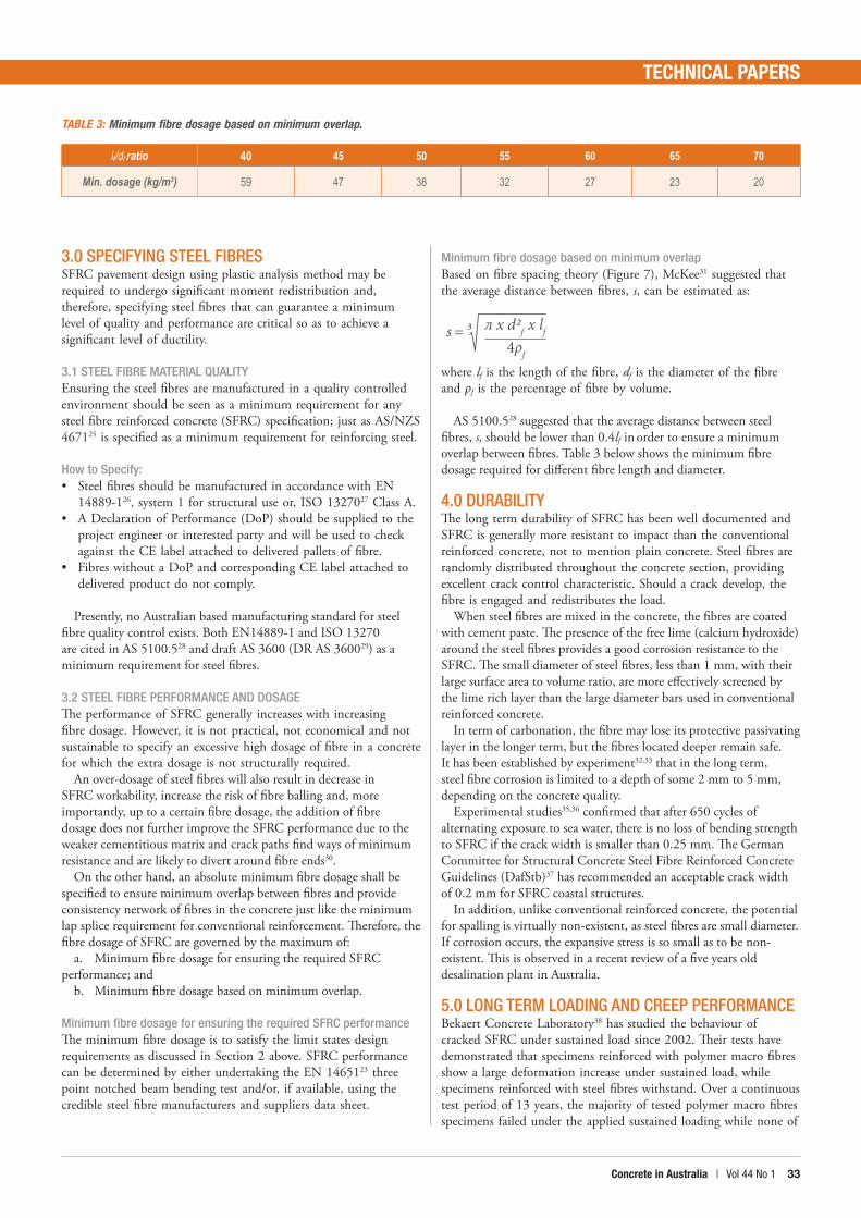
Minimum fibre dosage based on minimum overlap Based on fibre spacing theory (Figure 7), McKee31 suggested that the average distance between fibres, s, can be estimated as:
where lf is the length of the fibre, df is the diameter of the fibre and ρf is the percentage of fibre by volume.
AS 5100.528 suggested that the average distance between steel fibres, s, should be lower than 0.4lf in order to ensure a minimum overlap between fibres. Table 3 below shows the minimum fibre dosage required for different fibre length and diameter.
4.0 DURABILITYThe long term durability of SFRC has been well documented and SFRC is generally more resistant to impact than the conventional reinforced concrete, not to mention plain concrete. Steel fibres are randomly distributed throughout the concrete section, providing excellent crack control characteristic. Should a crack develop, the fibre is engaged and redistributes the load.
When steel fibres are mixed in the concrete, the fibres are coated with cement paste. The presence of the free lime (calcium hydroxide) around the steel fibres provides a good corrosion resistance to the SFRC. The small diameter of steel fibres, less than 1 mm, with their large surface area to volume ratio, are more effectively screened by the lime rich layer than the large diameter bars used in conventional reinforced concrete.
In term of carbonation, the fibre may lose its protective passivating layer in the longer term, but the fibres located deeper remain safe. It has been established by experiment32,33 that in the long term, steel fibre corrosion is limited to a depth of some 2 mm to 5 mm, depending on the concrete quality.
Experimental studies35,36 confirmed that after 650 cycles of alternating exposure to sea water, there is no loss of bending strength to SFRC if the crack width is smaller than 0.25 mm. The German Committee for Structural Concrete Steel Fibre Reinforced Concrete Guidelines (DafStb)37 has recommended an acceptable crack width of 0.2 mm for SFRC coastal structures.
In addition, unlike conventional reinforced concrete, the potential for spalling is virtually non-existent, as steel fibres are small diameter. If corrosion occurs, the expansive stress is so small as to be non-existent. This is observed in a recent review of a five years old desalination plant in Australia.
5.0 LONG TERM LOADING AND CREEP PERFORMANCEBekaert Concrete Laboratory38 has studied the behaviour of cracked SFRC under sustained load since 2002. Their tests have demonstrated that specimens reinforced with polymer macro fibres show a large deformation increase under sustained load, while specimens reinforced with steel fibres withstand. Over a continuous test period of 13 years, the majority of tested polymer macro fibres specimens failed under the applied sustained loading while none of
TABLE 3: Minimum fibre dosage based on minimum overlap.
lf/df ratio 40 45 50 55 60 65 70
Min. dosage (kg/m3) 59 47 38 32 27 23 20
s =3 л x d2f x lf
4ρf
Concrete in Australia | Vol 44 No 1 3534 Concrete in Australia | Vol 44 No 1
TECHNICAL PAPERS
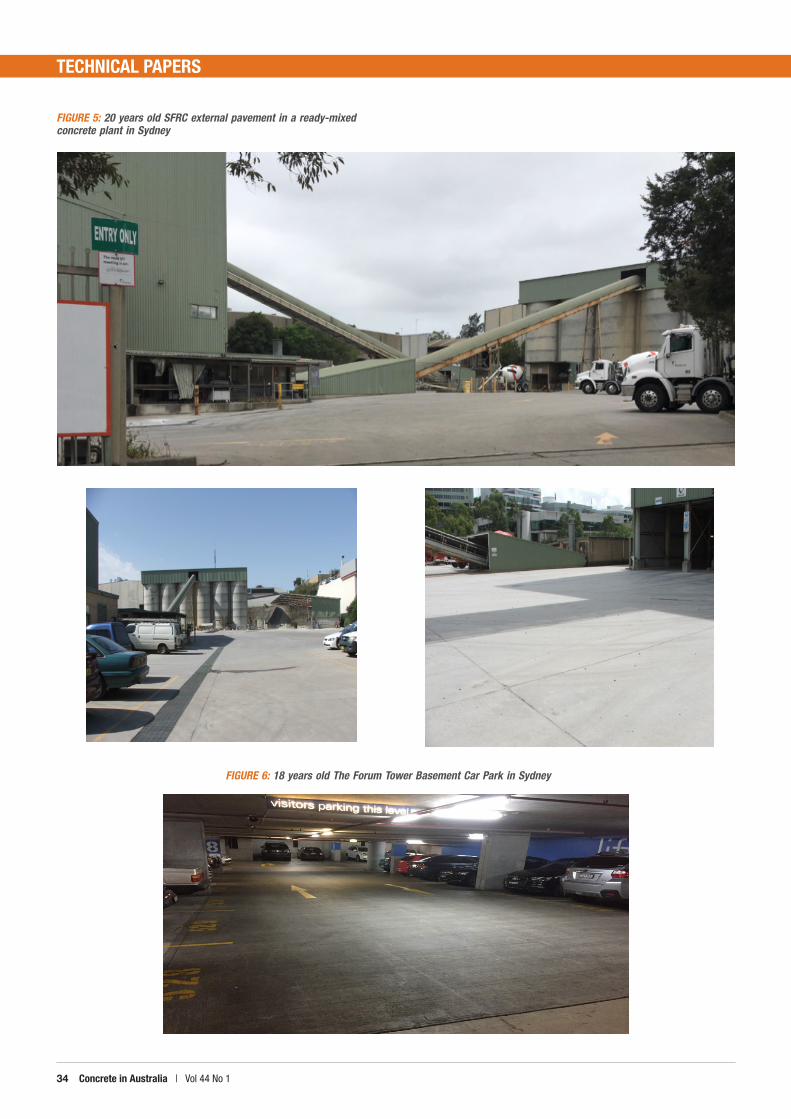
FIGURE 5: 20 years old SFRC external pavement in a ready-mixed concrete plant in Sydney
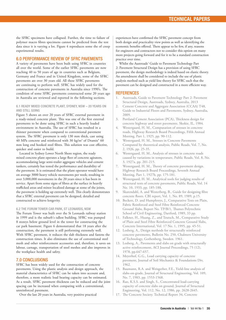
FIGURE 6: 18 years old The Forum Tower Basement Car Park in Sydney
Concrete in Australia | Vol 44 No 1 3534 Concrete in Australia | Vol 44 No 1
TECHNICAL PAPERS
the SFRC specimens have collapsed. Further, the time to failure of polymer macro fibres specimens cannot be predicted from the test data since it is varying a lot. Figure 4 reproduces some the of creep experimental results.
6.0 PERFORMANCE REVIEW OF SFRC PAVEMENTSA variety of pavements have been built using SFRC in countries all over the world. Some of the earlier SFRC pavements are now reaching 40 to 50 years of age in countries such as Belgium, Germany and France and in United Kingdom, some of the SFRC pavements are over 30 years old. All these SFRC pavements are continuing to perform well. SFRC has widely used for the construction of concrete pavements in Australia since 1990’s. The condition of some SFRC pavements constructed some 20 years ago in Australia are reviewed and reported in the following sections.
6.1 READY MIXED CONCRETE PLANT, SYDNEY, NSW – 20 YEARS ON AND STILL GOING Figure 5 shows an over 20 years of SFRC external pavement in a ready-mixed concrete plant. This was one of the first external pavements to be done using SFRC in such a heavily loaded environment in Australia. The use of SFRC has resulted in a thinner pavement when compared to conventional pavement system. The SFRC pavement is only 130 mm thick, cast using 40 MPa concrete and reinforced with 30 kg/m3 of Dramix® 60 mm long end hooked steel fibres. This solution was cost effective, quicker and easier to build.
Located in Sydney Lower North Shore region, the ready mixed concrete plant operates a large fleet of concrete agitators, accommodating large semi-trailer aggregate vehicles and cement tankers, certainly has tested the performance and durability of the pavement. It is estimated that the plant operator would have on average 3000 heavy vehicle movements per week; resulting in over 3,000,000 movements in the 20 years since it has been in service. Apart from some signs of fibres at the surface in heavily trafficked areas and minor localized damage at some of the joints, the pavement is holding up extremely well. This clearly demonstrates that a SFRC external pavement can be designed, detailed and constructed to achieve longevity.
6.2 THE FORUM TOWER CAR PARK, ST LEONARDS, NSW The Forum Tower was built over the St Leonards railway station in 1999 and is the suburb's tallest building. SFRC was pumped 8 storeys below ground level in the tower for constructing the car park basement. Figure 6 demonstrated that 18 years after the construction, the pavement is still performing extremely well. With SFRC pavement, it reduces the slab thickness and fastens the construction times. It also eliminates the use of conventional steel mesh and other reinforcement accessories and, therefore, it saves on labour, carnage, transportation of steel meshes and also improves in the workplace health and safety.
7.0 CONCLUSIONSSFRC has been widely used for the construction of concrete pavements. Using the plastic analysis and design approach, the material characteristics of SFRC can be taken into account and, therefore, a more realistic load bearing capacity can be estimated. As a result, SFRC pavement thickness can be reduced and the joint spacing can be increased when comparing with a conventional, unreinforced pavement.
Over the last 20 years in Australia, very positive practical
experiences have confirmed the SFRC pavement concept from both design and practicality view points as well as identifying the economic benefits offered. There appear to be few, if any, reasons for engineers and contractors not to consider this option on many more projects going forward and for it to be a standard construction practice over time.
Whilst the Austroads1 Guide to Pavement Technology Part 2: Pavement Structural Design has a provision of using SFRC pavement, the design methodology is indeed based on elastic theory. An amendment shall be considered to include the use of plastic analysis method such as yield line theory for SFRC such that the pavement can be designed and constructed in a more efficient way.
REFERENCES1. Austroads, Guide to Pavement Technology Part 2: Pavement
Structural Design, Austroads, Sydney, Australia, 20132. Cement Concrete and Aggregate Association (CCAA) T48,
Guide to Industrial Floors and Pavements, Sydney, Australia, 2009.
3. Portland Cement Association (PCA), Thickness design for concrete highway and street pavements. Skokie, IL, 1984.
4. Westergaard, H. M., Computation of stresses in concrete roads, Highway Research Board Proceedings, Fifth Annual Meeting, Part 1, 1925, pp. 90-112.
5. Westergaard, H. M., Stresses in Concrete Pavements Computed by theoretical analysis, Public Roads, Vol. 7, No. 2, 1926, pp. 25-35.
6. Westergaard, H. M., Analysis of stresses in concrete roads caused by variations in temperature, Public Roads, Vol. 8, No. 3, 1927a, pp. 201-215.
7. Westergaard, H. M., Theory of concrete pavement design. Highway Research Board Proceedings, Seventh Annual Meeting, Part 1, 1927b, pp. 175-181.
8. Westergaard, H. M., Analytical tools for judging results of structural tests of concrete pavements, Public Roads, Vol. 14 No. 10, 1933, pp. 185-188,
9. Skarendahl, A. and Westerberg, B., Guide for designing fibre concrete floors. CBI report, Vol. 1, No. 89, 1989, p.15.
10. Beckett, D. and Humphreys, J., Comparative Tests on Plain, Fabric Reinforced and Steel Fibre Reinforced Concrete Ground Slabs, Report No. TP/B/1, Thames Polytechnic School of Civil Engineering, Dartford, 1989, 33 pp.
11. Falkner, H., Huang, Z., and Teutsch, M., Comparative Study of Plain and Steel Fibre Reinforced Concrete Ground Slabs, Concrete International, Vol. 17 No. 1, 1995, pp. 45-51.
12. Losberg, A., Design methods for structurally reinforced concrete pavements, Bulletin No. 250, Chalmers University of Technology, Gothenberg, Sweden. 1961.
13. Losberg, A., Pavements and slabs on grade with structurally active reinforcement, ACI Journal Proceedings, 75 (12), 1978, pp.647-657.
14. Meyerhof, G.G., Load carrying capacity of concrete pavement, Journal of Soil Mechanics & Foundations Div, 1962.
15. Baumann, R.A. and Weisgerber, F.E., Yield-line analysis of slabs-on-grade, Journal of Structural Engineering, Vol. 109, No. 7, 1983, pp. 1553-1568.
16. Rao, K.S.S. and Singh, S., Concentrated load-carrying capacity of concrete slabs on ground, Journal of Structural Engineering, Vol. 112, No. 12, 1986, pp. 2628-2645.
17. The Concrete Society. Technical Report 34, Concrete
Concrete in Australia | Vol 44 No 1 PB36 Concrete in Australia | Vol 44 No 1
TECHNICAL PAPERS
industrial ground floors – a guide to their design and construction, Third Edition, Camberley, UK, 2003.
18. The Concrete Society. Technical Report 34, Concrete industrial ground floors – a guide to their design and construction. , Fourth Edition, Camberley, UK, 2014.
19. Beckett, D., Concrete industrial ground slabs. Chapter 1 - Design Applications of Raft Foundations, 2000, p. 1-38.
20. Ross, A., Joint free restrained slabs: SFRC combined with mesh, Australian Society for Concrete Pavements (ASCP), 2015, Coffs Harbour.
21. Ng, T. S., Structural Application of Steel Fibres Reinforced Concrete with and without Conventional Reinforcement, Proceedings of the 28th Biennial Conference of the Concrete Institute of Australia, October, 2017, Adelaide.
22. Alavizadeh-Farhang, A., Concrete structures subjected to combined mechanical and thermal loading. TRITA-BKN. Bulletin No. 60, 2000.
23. EN 14651, Test method for metallic fibre concrete. Measuring the flexural tensile strength (limit of proportionality (LOP), residual). British Standards institution, London, 2005.
24. Fédération internationale du béton (fib), fib model code for concrete structures 2010. Berlin, Germany, 2013.
25. AS/NZS 4671, Steel reinforcing materials, Standards Australia/Standards New Zealand, Sydney, 2001.
26. EN 14889-1, Fibres for concrete - Part 1: Steel fibres - Definitions, specifications and conformity, European Committee for Standardization, 2006.
27. ISO 13270, Steel fibres for concrete - Definitions and specifications, International Organization for Standardization, 2013.
28. AS 5100.5, Bridge Design Part 5: Concrete, Standards Australia, Sydney, 2017.
29. DR AS 3600, Draft for Public Comment Australian Standard - Concrete structures (Revision of AS 3600-2009), Standards
Australia, Sydney, 2017.30. Foster, S.J., Htut, T.N.S., and Ng, T.S., High performance
fibre reinforced concrete: fundamental behaviour and modelling, Proceedings of the 8th International Conference on Fracture Mechanics Concrete and Concrete Structures (FraMCoS-8), Toledo, Spain, 2013, pp. 69-78.
31. McKee, D.C., The Properties of an Expansive Cement Mortar Reinforced with Random Wire Fibers, Doctoral dissertation, University of Illinois at Urbana-Champaign, 1969.
32. Kern, E. and Schorn, H., 23 Jahre alter Stahlfaserbeton. Beton‐und Stahlbetonbau, Vol. 86, No. 9, 1991, pp. 205-208.
33. Nemegeer, D., Vanbrabant, J. and Stang, H., Final report on durability of steel fibre reinforced concrete. Subtask 5.1 Durability of SFRC, Brite Euram Project BRPR-CT98, 2000.
34. Dubois, F. and Nouguier, H., Durability of Steel Fibrous Concrete Used for the Manufacture of Containers for Nuclear Waste Storage. Elsevier Applied Science, 1989, pp. 573-581.
35. Hannant, D.J. and Edgington, J., Durability of steel fibre concrete. RILEM Symposium on Fibre Reinforced Cement and Concrete, Volume 1, September 1975, pp. 159-169.
36. Mangat, P.S. and Gurusamy, K., Permissible crack widths in steel fibre reinforced marine concrete, Materials and Structures, Vol. 20, No. 5, 1987, pp. 338-347.
37. Deutscher Ausschuß für Stahlbeton (DAfStb), Commentary on the DAfStb Guideline "Steel Fibre Reinforced Concrete" DAfStb-Heft 614, Berlin, Germany, 2015.
38. Van Bergen, S., Pouillon, S. and Vitt, G., Experiences from 14 Years of Creep Testing of Steel and Polymer Fiber Reinforced Concrete. In: Serna P., Llano-Torre A., Cavalaro S. (eds) Creep Behaviour in Cracked Sections of Fibre Reinforced Concrete. RILEM book series, Vol 14. Springer, Dordrech, 2017, pp. 41-52.
Related Documents


