Steel expansion joints General description of steel expansion joints Steel expansion joints are used in appliances, machines, apparatus and pipe systems where space is restricted ■ to compensate for movement ■ to compensate for expansion ■ to reduce tension ■ to absorb noise and oscillation transmission ■ to compensate for ground and foundation settlement ■ as adapters to compensate for installation inaccuracies ■ as dismantling pieces for fittings Steel expansion joints are flexible pipe connection elements and are used in a variety of industrial applica- tions: ■ Machine engineering ■ Domestic industry ■ Chemical industry ■ Process plant engineering ■ Gas and water supply ■ Exhaust technology STENFLEX ® steel expansion joints have served with distinction for more than 45 years. They are the preferred flexible pipe connection elements of choice in manufactured appliances, machinery, apparatus and piping en- gineering. Constant further development and in- novations update our product range to meet the needs of current and changing markets, and fulfil the re- quirements of industry in regard to: ■ Operating safety ■ Reliability ■ Pressure and temperature resistance ■ Vacuum stability ■ Flexibility ■ Impermeability ■ Corrosion resistance ■ No maintenance ■ Long service life The large-scale industrial manufac- ture of steel bellows, constant control of compliance with all manufacturing, business and quality processes in line with EN ISO 9001:2008 and decades of experience in the development and manufacture of steel expansion joints: all this guarantees a uniform product of the highest standard. It underlines the STENFLEX ® Quality Claim. Our expertise in expansion joint engi- neering is reflected in the long service life and consequently in the high op- erational reliability of our steel expan- sion joints, thanks to the excellent production functionality and quality. Purpose For decades our steel expansion joints have been used in a wide variety of applications, and guarantee trou- ble-free operation on-site. STENFLEX ® has been assessed and approved as manufacturer of steel ex- pansion joints, on the basis of AD norms of the Pressure Equipment Di- rective and international standards. Calculations are based among other factors, on AD 2000-B12, DIN EN 14917 and EJMA. STENFLEX ® steel expansion joints have been certified by numerous classification, and ac- ceptance societies, and bear the CE mark. Our engineers together with our R&D department are always available for technical consultation, and ready to help in solving specific application problems at any time. 6 1

Welcome message from author
This document is posted to help you gain knowledge. Please leave a comment to let me know what you think about it! Share it to your friends and learn new things together.
Transcript
Steel expansion jointsGeneral description of steel expansion joints
Steel expansion joints are used in appliances, machines, apparatus and pipe systems where space is restricted
■ to compensate for movement■ to compensate for expansion■ to reduce tension■ to absorb noise and oscillation
transmission■ to compensate for ground and
foundation settlement■ as adapters to compensate for
installation inaccuracies■ as dismantling pieces for fittings
Steel expansion joints are flexiblepipe connection elements and areused in a variety of industrial applica-tions:
■ Machine engineering■ Domestic industry■ Chemical industry■ Process plant engineering■ Gas and water supply■ Exhaust technology
STENFLEX® steel expansion jointshave served with distinction for morethan 45 years. They are the preferredflexible pipe connection elements ofchoice in manufactured appliances,machinery, apparatus and piping en-gineering.Constant further development and in-novations update our product rangeto meet the needs of current andchanging markets, and fulfil the re-quirements of industry in regard to:■ Operating safety■ Reliability■ Pressure and temperature
resistance■ Vacuum stability■ Flexibility■ Impermeability■ Corrosion resistance■ No maintenance■ Long service life
The large-scale industrial manufac-ture of steel bellows, constant controlof compliance with all manufacturing,business and quality processes in linewith EN ISO 9001:2008 and decadesof experience in the development andmanufacture of steel expansion joints:all this guarantees a uniform productof the highest standard. It underlinesthe STENFLEX® Quality Claim.
Our expertise in expansion joint engi-neering is reflected in the long servicelife and consequently in the high op-erational reliability of our steel expan-sion joints, thanks to the excellentproduction functionality and quality.
Purpose
For decades our steel expansionjoints have been used in a wide varietyof applications, and guarantee trou-ble-free operation on-site.
STENFLEX® has been assessed andapproved as manufacturer of steel ex-pansion joints, on the basis of ADnorms of the Pressure Equipment Di-rective and international standards.Calculations are based among otherfactors, on AD 2000-B12, DIN EN14917 and EJMA. STENFLEX® steelexpansion joints have been certifiedby numerous classification, and ac-ceptance societies, and bear the CEmark.
Our engineers together with our R&Ddepartment are always available fortechnical consultation, and ready tohelp in solving specific applicationproblems at any time.
61
STENFLEX® steel expansion jointsvary according to the following crite-ria:■ type (universal/lateral/angular ex-
pansion joints)■ pipe connection type (flange, weld-
ing end or threaded connection)■ material quality of the bellows (rat-
ed to the media transported in thepipes)
■ bellows structure (rated to themovement, pressure and tempera-ture load)
Our expansion joints are deliveredready for installation. STENFLEX®manufactures expansion joints innominal widths DN 15 – DN 2800 andfor nominal pressure rates PN 1 - PN25. A wide range of materials is used,with temperature resistance from–196 °C to +900 °C.
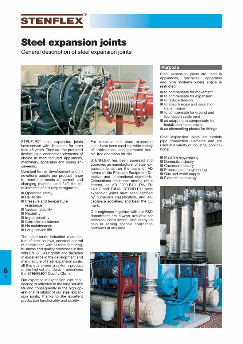
Lateral expansion jointsStructure:Steel bellows with laterally movable restraints and flanges or welding ends. Movement absorption:Lateral shift of the expansion joint is possible. The restraint absorbs axial reac-tion force and relieves the pressure on the pipe's fixed points. Lateral expansionjoints, with two bellows and a connecting pipe are used to absorb large move-ment.Fixed points:Only light fixed points are required to absorb lateral movement and frictionforce.
Axial expansion jointsStructure:Steel bellows with connection parts (flange, welding end or threaded connec-tion). Movement absorption:Axial shift, and slight all-round movement of the expansion joint is possible. Ax-ial expansion joints with two bellows are used to absorb larger movement.Fixed points:Robust pipe fixed points and correct pipe routing are necessary to absorb theaxial forces.
Angular expansion jointsStructure:Steel bellows with hinge restraint and flanges or welding ends. The rotating axis ofthe hinge restraint is in the middle of the bellows. Movement absorption:Angular movement of the expansion joint is possible. The angular joints regu-late a defined angular movement, absorb axial reaction force and relieve thepressure on the pipe's fixed points. We differentiate between angular expansion joints with a hinge (bellows angularmovement guided on one plane) and angular expansion joints with a cardanhinge restraint (bellows movement guided on two planes).Fixed points: Only light fixed points are required to absorb angular movementforce and friction force.
Together with the standard and basicversions featured in the catalogue,special versions can also be devel-oped and produced on request, forspecial operating conditions or spe-cial structures.
Connection parts (that deviate fromDIN) such as EN, ISO, ANSI, VG, SAEstandards etc. are also available.
STENFLEX® steel expansion joints arerated theoretically using state-of-the-art computing techniques (which in-clude the Finite Element Method).They are optimized under experimen-tal conditions. National and interna-tional calculation standards are usedto rate the bellows.Our development engineers use themost up-to-date development toolsthroughout the development stage tovalidate the construction process interms of form, function and installa-
tion. Hence we can offer our cus-tomers the following advantages:
Development/Design
Versions
■ Design and development in linewith the specific requirements, re-sulting in safe and extremelydurable expansion joints
■ Efficient products by incorporatingsuperior functionality
■ Structures that are easy to install■ Reduced lead times for special
designs
62
Bellowsmaterial
Food-product industry, film and photo industry, nitrogen fertilizer industry, silencerand exhaust purification systems, low tem-perature technology
Chemical industry, oil, soap and textile industries, dyeing plant, dairies, breweries,pharmaceutical industry, petrochemical andcoal-tar industry, water supply and watertreatment
Furnace and apparatus construction, airpre-heaters, steel and metallurgical industry
Steel and metallurgical industry
Chemical engineering, plant for air purifica-tion, oil and gas extraction, reprocessingplant, acid production, petrol facilities
Material qualitiesSTENFLEX® expansion joint bellowsare manufactured from top qualitysheet metal. Different material quali-ties are used to cover the many oper-ating conditions in various industrialapplications.
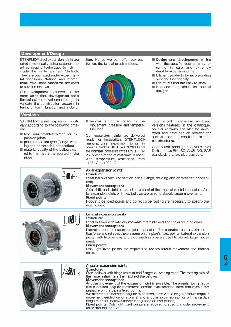
StructureSTENFLEX® steel bellows are avail-able in a variety of structures and ver-sions. The steel bellows is the flexibleelement of every expansion joint. Itmust fulfil the requirement for goodmovability with simultaneous pres-sure resistance.
Variable parameters (wall thickness,number of plies, convolution geome-try, number of convolutions) deter-mine the pressure resistance, move-ment absorption and spring rate (self-resisting force) of the bellows. One-ply, two-ply and multi-ply bellows aremanufactured from various materialswith different wall thicknesses.
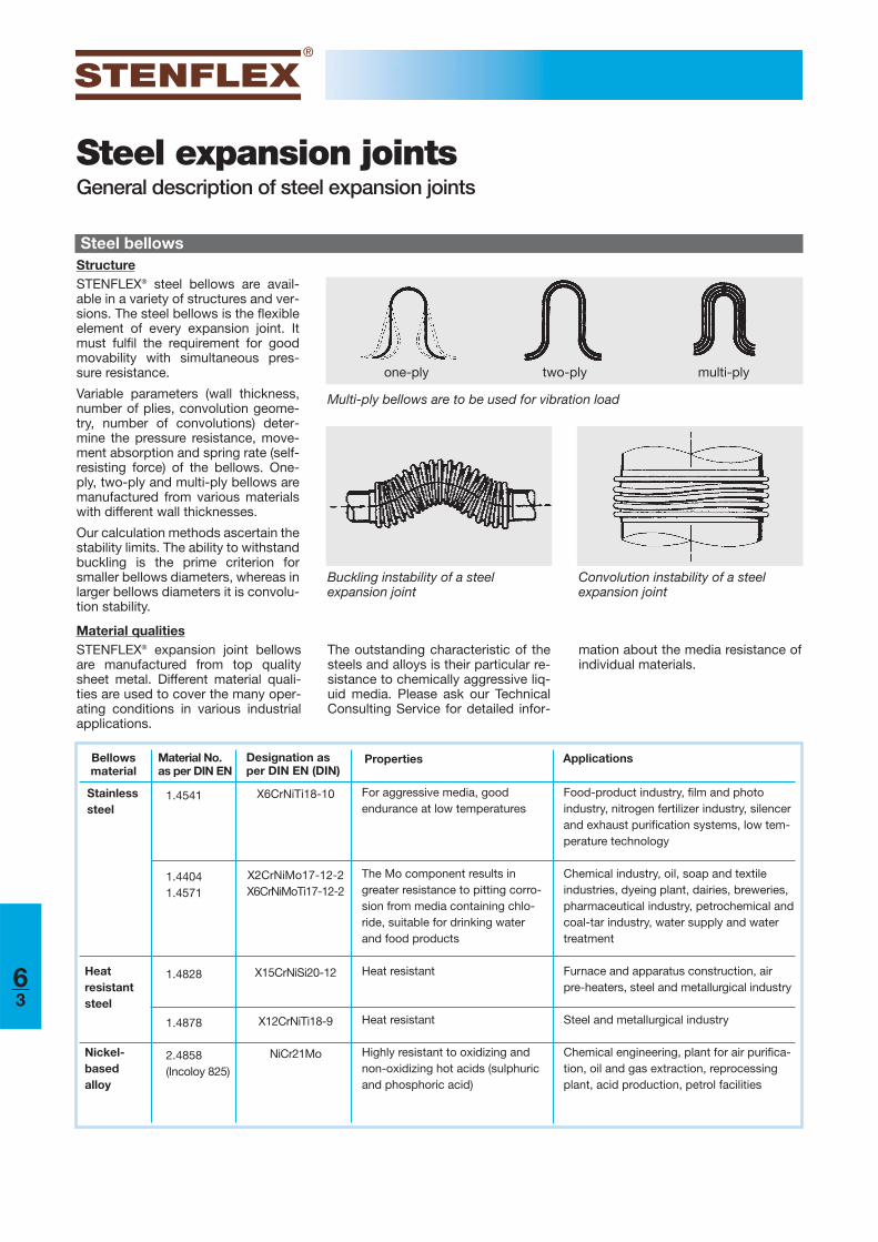
Our calculation methods ascertain thestability limits. The ability to withstandbuckling is the prime criterion forsmaller bellows diameters, whereas inlarger bellows diameters it is convolu-tion stability.
Steel expansion jointsGeneral description of steel expansion joints
Steel bellows
one-ply two-ply multi-ply
Buckling instability of a steel expansion joint
Convolution instability of a steel expansion joint
Properties Applications
Stainlesssteel
For aggressive media, good endurance at low temperatures
The Mo component results ingreater resistance to pitting corro-sion from media containing chlo-ride, suitable for drinking waterand food products
Heat resistant
Heat resistant
Highly resistant to oxidizing andnon-oxidizing hot acids (sulphuricand phosphoric acid)
Material No.as per DIN EN
1.4541
1.44041.4571
1.4828
1.4878
2.4858(Incoloy 825)
X6CrNiTi18-10
X2CrNiMo17-12-2X6CrNiMoTi17-12-2
X15CrNiSi20-12
X12CrNiTi18-9
NiCr21Mo
Designation asper DIN EN (DIN)
Heatresistantsteel
Nickel-based alloy
The outstanding characteristic of thesteels and alloys is their particular re-sistance to chemically aggressive liq-uid media. Please ask our TechnicalConsulting Service for detailed infor-
Multi-ply bellows are to be used for vibration load
mation about the media resistance ofindividual materials.
63
Rating, service life
Steel bellows, as a rule, are rated for atemperature of +20 °C, the nominalpressure and a load of 1000 load cy-cles.
One load cycle refers to the proce-dure beginning at zero position, fromwhere the expansion joint moves tothe maximum elongation (positive)position, back through the zero posi-tion to the maximum compression(negative) position, and back to thezero position.
Together with the tolerable operatingconditions
■ pressure■ temperature■ movement■ number of load cycles
the following parameters can also in-fluence the service life of expansionjoints:
■ corrosion■ high-frequency oscillations■ sympathetic vibration■ pressure shocks■ temperature shocks■ incorrect installation
Corrosion can be caused by incorrectselection or combination of materials,conveyance of aggressive media andinappropriate cleaning with chemicalagents.
High-frequency oscillations and sym-pathetic vibration must be avoided byall means, because this will result infatigue failure/fracture.
Pressure and temperature shocksmust be avoided. It is important not toexceed the permitted maximum val-ues.
Incorrect installation can be prevent-ed by compliance with our installationand assembly instructions.
In the case of unrestrained expansionjoints, the absence of fixed points cancause the pipeline to shift. This usual-ly destroys the expansion joint.
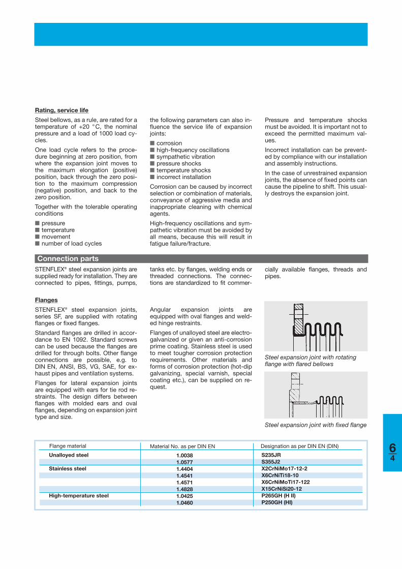
Steel expansion joint with rotatingflange with flared bellows
Steel expansion joint with fixed flange
tanks etc. by flanges, welding ends orthreaded connections. The connec-tions are standardized to fit commer-
Flanges
STENFLEX® steel expansion joints,series SF, are supplied with rotatingflanges or fixed flanges.
Standard flanges are drilled in accor-dance to EN 1092. Standard screwscan be used because the flanges aredrilled for through bolts. Other flangeconnections are possible, e.g. toDIN EN, ANSI, BS, VG, SAE, for ex-haust pipes and ventilation systems.
Flanges for lateral expansion jointsare equipped with ears for tie rod re-straints. The design differs betweenflanges with molded ears and ovalflanges, depending on expansion jointtype and size.
Connection parts
Angular expansion joints areequipped with oval flanges and weld-ed hinge restraints.
Flanges of unalloyed steel are electro-galvanized or given an anti-corrosionprime coating. Stainless steel is usedto meet tougher corrosion protectionrequirements. Other materials andforms of corrosion protection (hot-dipgalvanizing, special varnish, specialcoating etc.), can be supplied on re-quest.
STENFLEX® steel expansion joints aresupplied ready for installation. They areconnected to pipes, fittings, pumps,
cially available flanges, threads andpipes.
Flange material Material No. as per DIN EN Designation as per DIN EN (DIN)
Unalloyed steel
Stainless steel
High-temperature steel
1.0038 1.05771.44041.45411.45711.48281.04251.0460
S235JRS355J2X2CrNiMo17-12-2X6CrNiTi18-10X6CrNiMoTi17-122X15CrNiSi20-12P265GH (H II)P250GH (HI)
64
Steel expansion jointsGeneral description of steel expansion joints
Welding end material Material No. as per DIN EN Designation as per DIN EN (DIN)
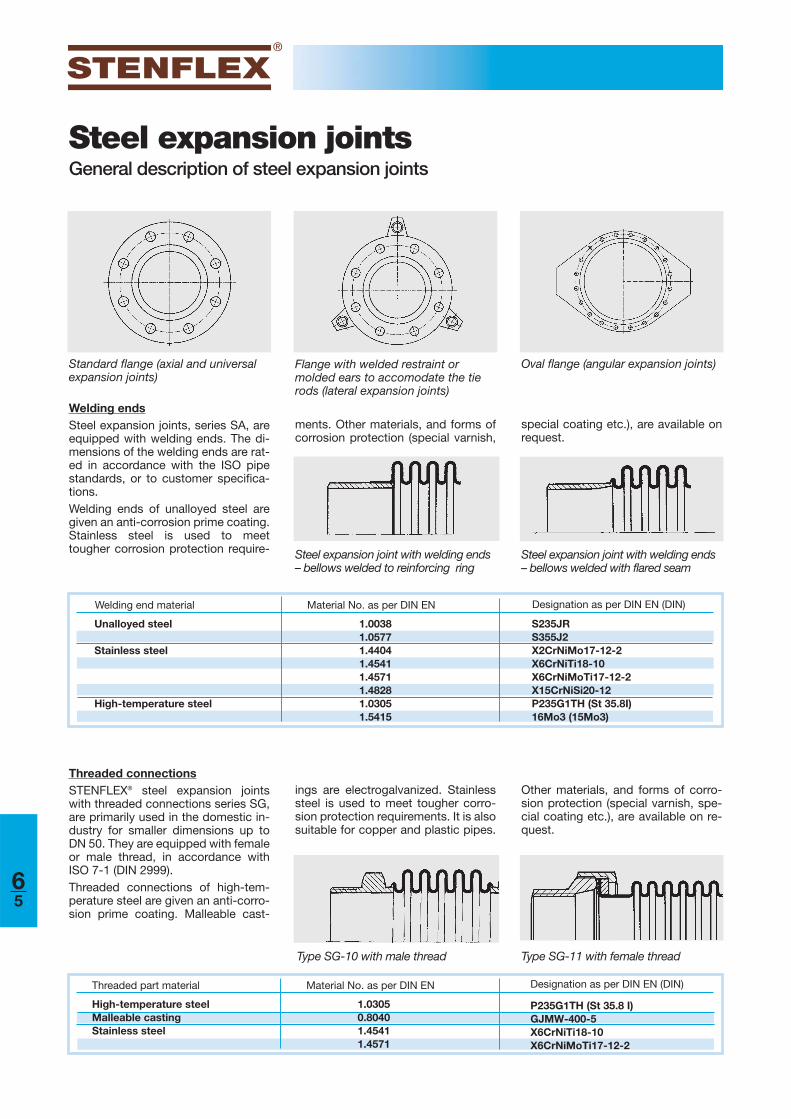
Threaded connectionsSTENFLEX® steel expansion jointswith threaded connections series SG,are primarily used in the domestic in-dustry for smaller dimensions up toDN 50. They are equipped with femaleor male thread, in accordance withISO 7-1 (DIN 2999).Threaded connections of high-tem-perature steel are given an anti-corro-sion prime coating. Malleable cast-
Welding endsSteel expansion joints, series SA, areequipped with welding ends. The di-mensions of the welding ends are rat-ed in accordance with the ISO pipestandards, or to customer specifica-tions. Welding ends of unalloyed steel aregiven an anti-corrosion prime coating.Stainless steel is used to meettougher corrosion protection require-
Type SG-10 with male thread
Steel expansion joint with welding ends– bellows welded to reinforcing ring
Steel expansion joint with welding ends– bellows welded with flared seam
Type SG-11 with female thread
ments. Other materials, and forms ofcorrosion protection (special varnish,
ings are electrogalvanized. Stainlesssteel is used to meet tougher corro-sion protection requirements. It is alsosuitable for copper and plastic pipes.
Threaded part material Material No. as per DIN EN Designation as per DIN EN (DIN)
High-temperature steelMalleable castingStainless steel
1.03050.80401.45411.4571
P235G1TH (St 35.8 I)GJMW-400-5X6CrNiTi18-10X6CrNiMoTi17-12-2
Other materials, and forms of corro-sion protection (special varnish, spe-cial coating etc.), are available on re-quest.
special coating etc.), are available onrequest.
Standard flange (axial and universal expansion joints)
Oval flange (angular expansion joints)Flange with welded restraint or molded ears to accomodate the tierods (lateral expansion joints)
Unalloyed steel
Stainless steel
High-temperature steel
1.00381.05771.44041.45411.45711.48281.03051.5415
S235JRS355J2X2CrNiMo17-12-2X6CrNiTi18-10X6CrNiMoTi17-12-2X15CrNiSi20-12P235G1TH (St 35.8I)16Mo3 (15Mo3)
65
Material tie rod restraint
Designation as per DIN EN (DIN) or strength class
Unalloyed steelEarsTie rodsNutsSpherical washers/conical seats
Stainless steelEars
Tie rods, nuts
Spherical washers/conical seatsHigh-temperature steel
EarsTie rods, nuts
S235JR5.6, 8.85, 8C15
X6CrNiTi18-10X6CrNiMoTi17-12-250, 7050, 70X8CrNiS18-9
16Mo3 (15Mo3)42CrMo421CrMoV5-7
Material No. as per DIN EN
1.0038
1.0401
1.45411.4571
A2A4
1.4305
1.54151.72251.7709
Restraints
Outer restraint with spherical washersand conical seats (lateral expansion joints)
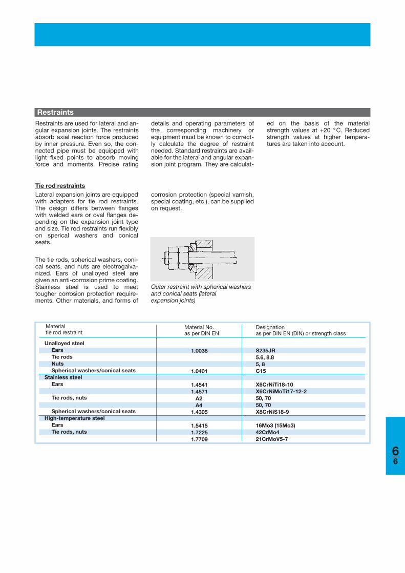
details and operating parameters ofthe corresponding machinery orequipment must be known to correct-ly calculate the degree of restraintneeded. Standard restraints are avail-able for the lateral and angular expan-sion joint program. They are calculat-
Restraints are used for lateral and an-gular expansion joints. The restraintsabsorb axial reaction force producedby inner pressure. Even so, the con-nected pipe must be equipped withlight fixed points to absorb movingforce and moments. Precise rating
ed on the basis of the materialstrength values at +20 °C. Reducedstrength values at higher tempera-tures are taken into account.
Tie rod restraintsLateral expansion joints are equippedwith adapters for tie rod restraints.The design differs between flangeswith welded ears or oval flanges de-pending on the expansion joint typeand size. Tie rod restraints run flexiblyon sperical washers and conicalseats.
The tie rods, spherical washers, coni-cal seats, and nuts are electrogalva-nized. Ears of unalloyed steel are given an anti-corrosion prime coating.Stainless steel is used to meettougher corrosion protection require-ments. Other materials, and forms of
corrosion protection (special varnish,special coating, etc.), can be suppliedon request.
66
Steel expansion jointsGeneral description of steel expansion joints
STENFLEX® steel expansion jointscan be provided with the followingaccessories:■ Internal guide sleeve■ Guide sleeve■ Protective cover
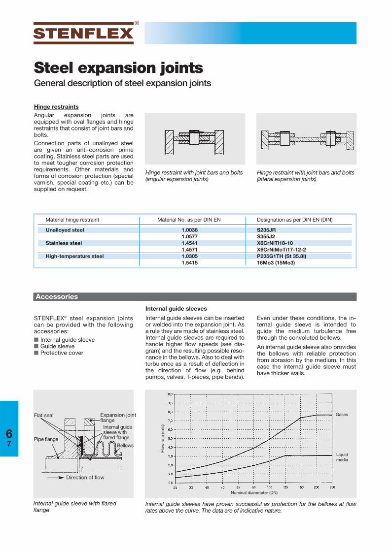
Internal guide sleeves
Internal guide sleeves can be insertedor welded into the expansion joint. Asa rule they are made of stainless steel.Internal guide sleeves are required tohandle higher flow speeds (see dia-gram) and the resulting possible reso-nance in the bellows. Also to deal withturbulence as a result of deflection inthe direction of flow (e.g. behindpumps, valves, T-pieces, pipe bends).
Even under these conditions, the in-ternal guide sleeve is intended toguide the medium turbulence freethrough the convoluted bellows.
An internal guide sleeve also providesthe bellows with reliable protectionfrom abrasion by the medium. In thiscase the internal guide sleeve musthave thicker walls.
Internal guide sleeves have proven successful as protection for the bellows at flowrates above the curve. The data are of indicative nature.
Internal guide sleeve with flaredflange
Expansion jointflange
Internal guidesleeve with flared flange
BellowsPipe flange
Flat seal
Direction of flow
Accessories
Hinge restraint with joint bars and bolts(angular expansion joints)
Material hinge restraint Material No. as per DIN EN Designation as per DIN EN (DIN)
Unalloyed steel
Stainless steel
High-temperature steel
1.00381.05771.45411.45711.03051.5415
S235JRS355J2X6CrNiTi18-10X6CrNiMoTi17-12-2P235G1TH (St 35.8I)16Mo3 (15Mo3)
Hinge restraintsAngular expansion joints areequipped with oval flanges and hingerestraints that consist of joint bars andbolts.Connection parts of unalloyed steelare given an anti-corrosion primecoating. Stainless steel parts are usedto meet tougher corrosion protectionrequirements. Other materials andforms of corrosion protection (specialvarnish, special coating etc.) can besupplied on request.
Hinge restraint with joint bars and bolts(lateral expansion joints)
Gases
Liquidmedia
Nominal diameteter (DN)
Flow
rat
e (m
/s)
67
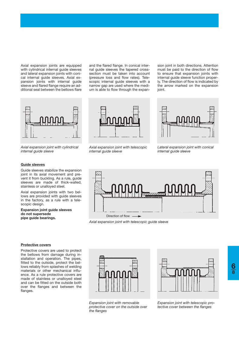
Guide sleeves
Guide sleeves stabilize the expansionjoint in its axial movement and pre-vent it from buckling. As a rule, guidesleeves are made of thick-walled,stainless or unalloyed steel.
Axial expansion joints with two bel-lows are provided with guide sleevesin the factory, as a rule with a tele-scopic design.
Expansion joint guide sleeves do not supersede pipe guide bearings.
Axial expansion joint with telescopic guide sleeve
Protective covers
Protective covers are used to protectthe bellows from damage during in-stallation and operation. The pipes,fitted to the outside, protect the bel-lows reliably from splashes of weldingmaterials or other mechanical influ-ence. As a rule protective covers aremade of stainless or unalloyed steeland can be fitted on the outside bothover the flanges and between theflanges.
Expansion joint with removable protective cover on the outside overthe flanges
Expansion joint with telescopic pro-tective cover between the flanges
Direction of flow
Axial expansion joint with cylindrical internal guide sleeve
Axial expansion joint with telescopic internal guide sleeve
Axial expansion joints are equippedwith cylindrical internal guide sleevesand lateral expansion joints with coni-cal internal guide sleeves. Axial ex-pansion joints with internal guidesleeve and flared flange require an ad-ditional seal between the bellows flare
Lateral expansion joint with conical internal guide sleeve
and the flared flange. In conical inter-nal guide sleeves the tapered cross-section must be taken into account(pressure loss and flow rates). Tele-scopic internal guide sleeves with anarrow gap are used where the medi-um is able to flow through the expan-
sion joint in both directions. Attentionmust be paid to the direction of flowto ensure that expansion joints withinternal guide sleeve function proper-ly. The direction of flow is indicated bythe arrow marked on the expansionjoint.
68
Steel expansion jointsCompensation systems
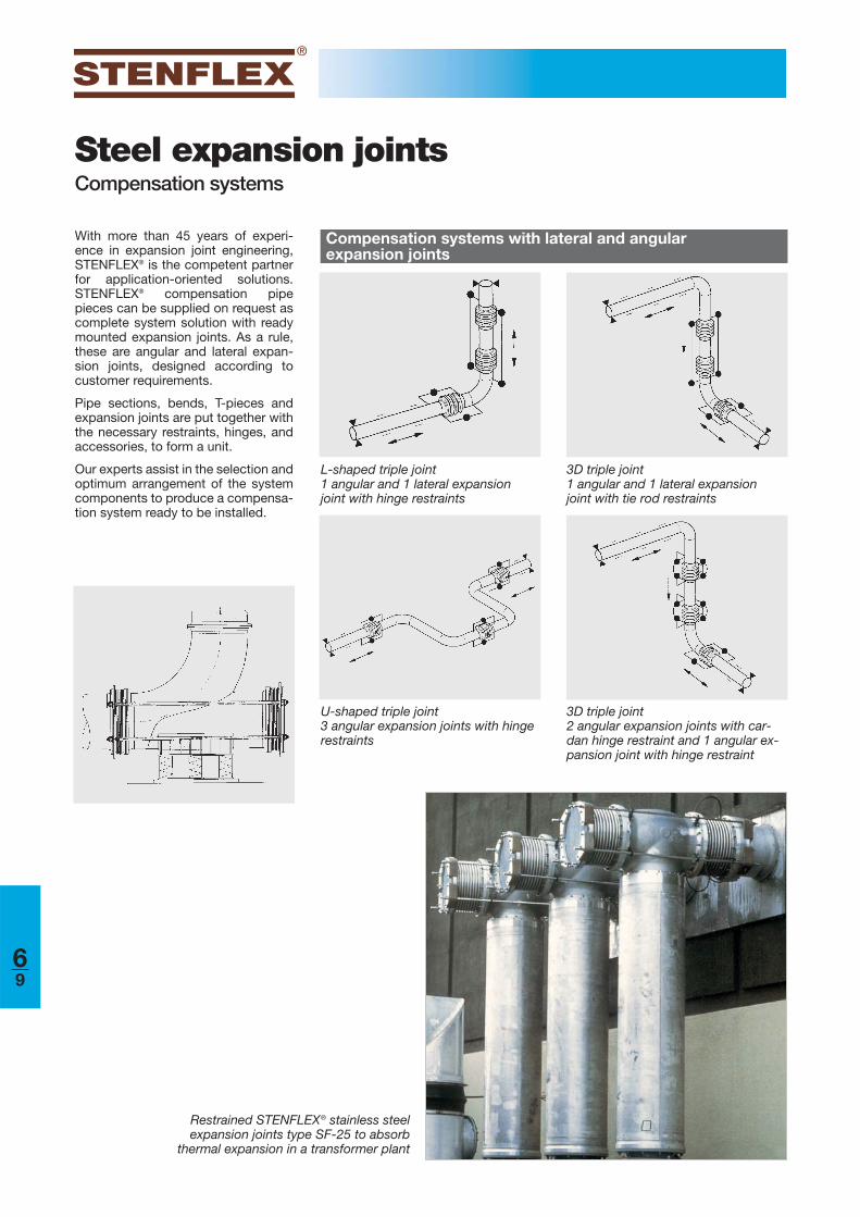
With more than 45 years of experi-ence in expansion joint engineering,STENFLEX® is the competent partnerfor application-oriented solutions.STENFLEX® compensation pipepieces can be supplied on request ascomplete system solution with readymounted expansion joints. As a rule,these are angular and lateral expan-sion joints, designed according tocustomer requirements.
Pipe sections, bends, T-pieces andexpansion joints are put together withthe necessary restraints, hinges, andaccessories, to form a unit.
Our experts assist in the selection andoptimum arrangement of the systemcomponents to produce a compensa-tion system ready to be installed.
Compensation systems with lateral and angular expansion joints
L-shaped triple joint1 angular and 1 lateral expansionjoint with hinge restraints
3D triple joint 1 angular and 1 lateral expansionjoint with tie rod restraints
U-shaped triple joint3 angular expansion joints with hingerestraints
3D triple joint2 angular expansion joints with car-dan hinge restraint and 1 angular ex-pansion joint with hinge restraint
Restrained STENFLEX® stainless steel expansion joints type SF-25 to absorb
thermal expansion in a transformer plant
69
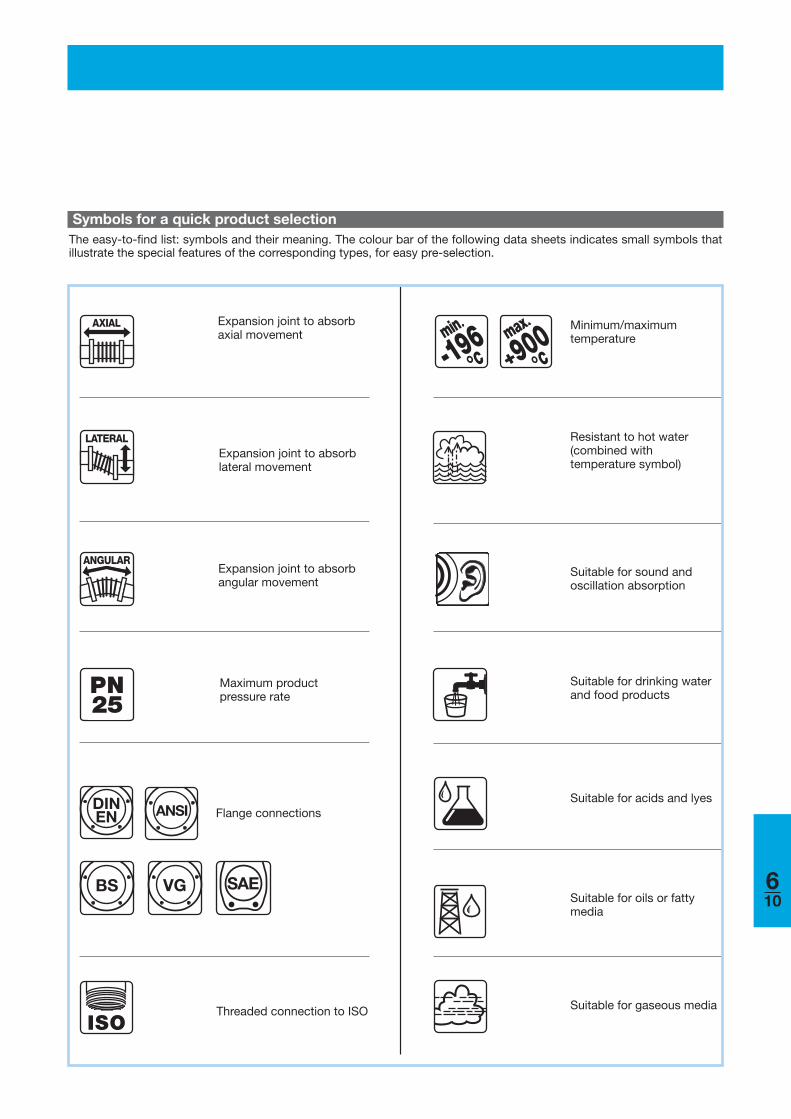
900°
Minimum/maximum temperature
Symbols for a quick product selection
ISO
Expansion joint to absorb axial movement
Threaded connection to ISO
Resistant to hot water (combined with temperature symbol)
Suitable for drinking waterand food products
Suitable for acids and lyes
Suitable for oils or fatty media
Suitable for gaseous media
DINEN ANSI
Expansion joint to absorb lateral movement
Expansion joint to absorb angular movement
Maximum product pressure rate
Flange connections
The easy-to-find list: symbols and their meaning. The colour bar of the following data sheets indicates small symbols thatillustrate the special features of the corresponding types, for easy pre-selection.
Suitable for sound and oscillation absorption
25
BS VG SAE
-196min
°°
610
Steel expansion jointsApplications/Possible uses/Industries
611
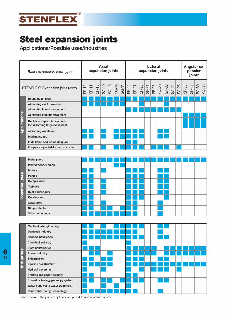
Metal pipes
Plastic/copper pipes
Motors
Pumps
Compressors
Turbines
Heat exchangers
Condensers
Separators
Biogas plants
Solar technology
Reducing tension
Absorbing axial movement
Absorbing lateral movement
Absorbing angular movement
Double or triple joint systems for absorbing large movement
Absorbing oscillation
Muffling sound
Installation and dismantling aid
Compensating for installation inaccuracies
SF-1
0
SF-1
1
SF-1
3
SA-1
0
SA-1
3
SG-1
0
SG-1
1
SF-2
0
SF-2
1
SF-2
3
SF-2
4
SF-2
5
SA-2
0
SA-2
3
SA-2
4
SA-2
5
SF-3
2
SF-3
3
SA-3
0
SA-3
3
App
licat
ions
Po
ssib
le u
ses
Basic expansion joint types
STENFLEX® Expansion joint types
Axial expansion joints
Lateral expansion joints
Angular ex-pansion
joints
Table showing the prime applications, possible uses and industries.
Mechanical engineering
Domestic industry
Heating installation
Chemical industry
Plant construction
Power industry
Shipbuilding
Pipeline construction
Hydraulic systems
Printing and paper industry
Exhaust technology/gas supply systems
Water supply and water treatment
Renewable energy technology
Ind
ustr
ies
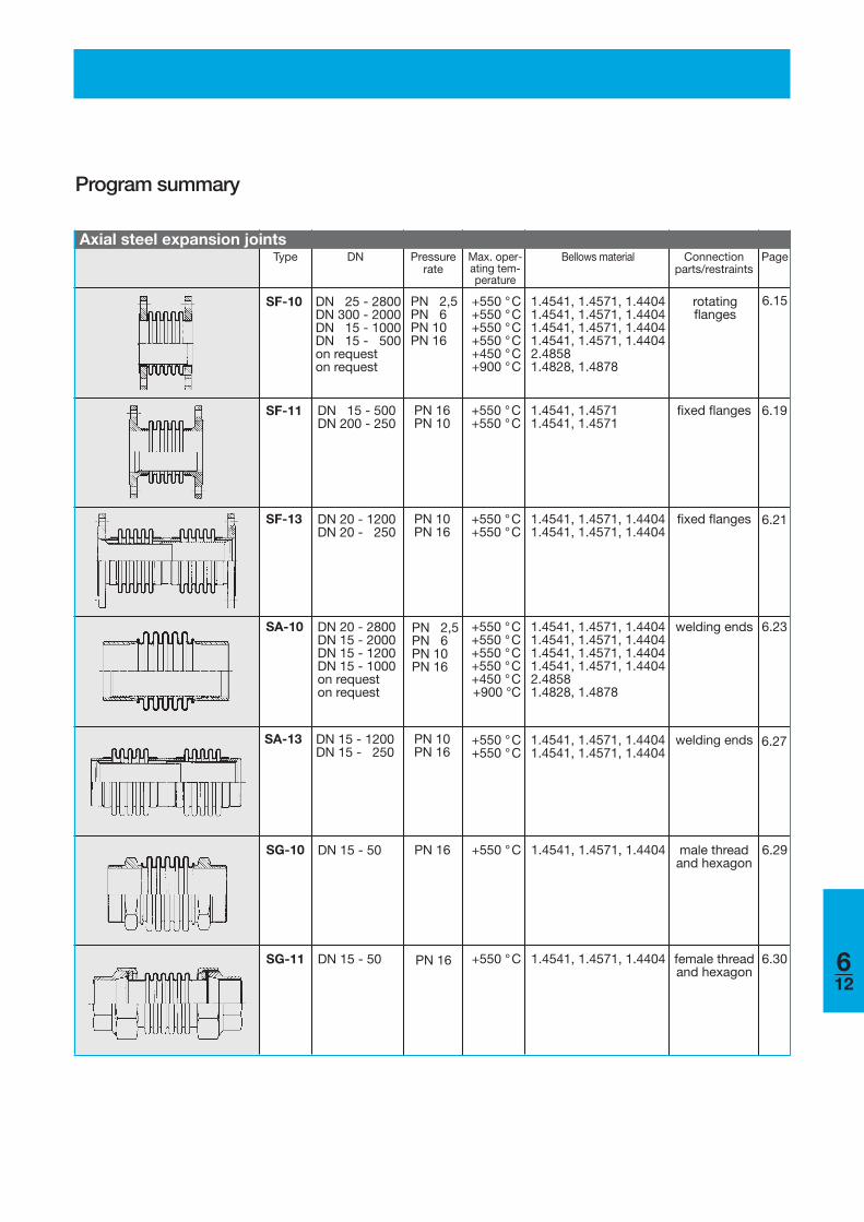
Program summary
Type DN Pressurerate
Max. oper-ating tem-perature
Bellows material Connectionparts/restraints
Page
612
SF-10 DN 25 - 2800DN 300 - 2000DN 15 - 1000DN 15 - 500on requeston request
PN 2,5PN 6PN 10PN 16
+550 °C+550 °C+550 °C+550 °C+450 °C+900 °C
1.4541, 1.4571, 1.44041.4541, 1.4571, 1.44041.4541, 1.4571, 1.44041.4541, 1.4571, 1.44042.48581.4828, 1.4878
rotatingflanges
DN 15 - 500DN 200 - 250
PN 16PN 10
+550 °C+550 °C
1.4541, 1.45711.4541, 1.4571
fixed flanges 6.19
DN 20 - 1200DN 20 - 250
PN 10PN 16
+550 °C+550 °C
1.4541, 1.4571, 1.44041.4541, 1.4571, 1.4404
fixed flanges 6.21
DN 20 - 2800DN 15 - 2000DN 15 - 1200DN 15 - 1000on requeston request
+550 °C+550 °C+550 °C+550 °C+450 °C+900 °C
1.4541, 1.4571, 1.44041.4541, 1.4571, 1.44041.4541, 1.4571, 1.44041.4541, 1.4571, 1.44042.48581.4828, 1.4878
welding ends 6.23
DN 15 - 1200DN 15 - 250
PN 10PN 16
+550 °C+550 °C
1.4541, 1.4571, 1.44041.4541, 1.4571, 1.4404
welding ends 6.27
SF-11
SF-13
SA-10
SA-13
Axial steel expansion joints
PN 2,5PN 6PN 10PN 16
6.15
DN 15 - 50 PN 16 +550 °C 1.4541, 1.4571, 1.4404 male threadand hexagon
DN 15 - 50 PN 16 +550 °C 1.4541, 1.4571, 1.4404 female threadand hexagon
6.29SG-10
SG-11 6.30
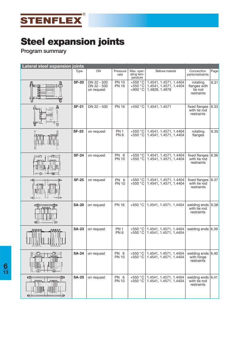
Steel expansion jointsProgram summary
Type DN Pressurerate
Max. oper-ating tem-perature
Bellows material Connectionparts/restraints
Page
613
SF-24 on request PN 6PN 10
+550 °C+550 °C
1.4541, 1.4571, 1.44041.4541, 1.4571, 1.4404
fixed flangeswith tie rodrestraints
6.36
on request +550 °C+550 °C
1.4541, 1.4571, 1.44041.4541, 1.4571, 1.4404
fixed flangeswith tie rodrestraints
6.37
on request PN 16 +550 °C 1.4541, 1.4571, 1.4404 welding endswith tie rodrestraints
6.38
SF-25
SA-20
Lateral steel expansion joints
PN 6PN 10
DN 32 - 500DN 32 - 500on request
PN 10PN 16
+550 °C+550 °C+900 °C
1.4541, 1.4571, 1.44041.4541, 1.4571, 1.44041.4828, 1.4878
rotatingflanges with
tie rod restraints
DN 32 - 500 PN 16 +550 °C 1.4541, 1.4571 fixed flangeswith tie rodrestraints
on request PN 1PN 6
+550 °C+550 °C
1.4541, 1.4571, 1.44041.4541, 1.4571, 1.4404
rotatingflanges
SF-20
SF-21
SF-23
6.31
6.33
6.35
+550 °C+550 °C
on request PN 1PN 6
1.4541, 1.4571, 1.44041.4541, 1.4571, 1.4404
welding ends 6.39
on request PN 6PN 10
+550 °C+550 °C
1.4541, 1.4571, 1.44041.4541, 1.4571, 1.4404
welding endswith hingerestraints
6.40
on request PN 6PN 10
+550 °C+550 °C
1.4541, 1.4571, 1.44041.4541, 1.4571, 1.4404
welding endswith tie rodrestraints
6.41
SA-23
SA-24
SA-25
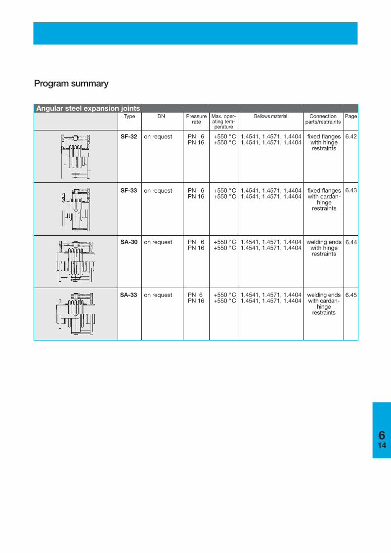
Program summary
Type DN Pressurerate
Max. oper-ating tem-perature
Bellows material Connectionparts/restraints
Page
614
on request PN 6PN 16
+550 °C+550 °C
1.4541, 1.4571, 1.44041.4541, 1.4571, 1.4404
fixed flangeswith hinge restraints
on request PN 6PN 16
+550 °C+550 °C
1.4541, 1.4571, 1.44041.4541, 1.4571, 1.4404
fixed flangeswith cardan-
hinge restraints
on request PN 6PN 16
+550 °C+550 °C
1.4541, 1.4571, 1.44041.4541, 1.4571, 1.4404
welding endswith hingerestraints
on request PN 6PN 16
+550 °C+550 °C
1.4541, 1.4571, 1.44041.4541, 1.4571, 1.4404
welding endswith cardan-
hinge restraints
SF-32
Angular steel expansion joints
SF-33
SA-30
SA-33
6.42
6.43
6.44
6.45
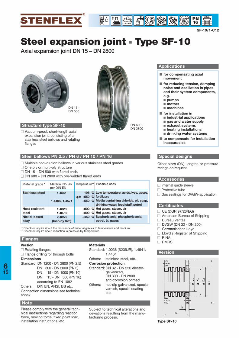
Version
Steel expansion joint ■ Type SF-10Axial expansion joint DN 15 – DN 2800
■ for compensating axial movement
■ for reducing tension, dampingnoise and oscillation in pipesand their system components,e.g. ■ pumps■ motors■ machines
■ for installation in■ industrial applications■ gas and water supply■ exhaust systems■ heating installations■ drinking water systems
■ to compensate for installationinaccuracies
Applications
SF-10/1-C12
900°° -196min
°DINEN
Structure type SF-10■■ Vacuum-proof, short-length axial
expansion joint, consisting of astainless steel bellows and rotatingflanges
Special designs
Other sizes (DN), lengths or pressureratings on request.
FlangesVersion■■ Rotating flanges■■ Flange drilling for through boltsDimensionsStandard: DN 1200 - DN 2800 (PN 2,5)
DN 300 - DN 2000 (PN 6)DN 15 - DN 1000 (PN 10)DN 15 - DN 500 (PN 16)according to EN 1092
Others: DIN EN, ANSI, BS etc.Connection dimensions see technicalannex
Accessories■■ Internal guide sleeve■■ Protective tube■■ Gas sealings for DVGW-application
NotePlease comply with the general tech-nical instructions regarding reactionforce, moving force, fixed point load,installation instructions, etc.
Certificates■■ CE (DGR 97/23/EG)■■ American Bureau of Shipping■■ Bureau Veritas■■ DVGW (DN 32 - DN 200)■■ Germanischer Lloyd■■ Lloyd´s Register of Shipping■■ RINA■■ RMRS
DN 15 - DN 500
MaterialsStandard: 1.0038 (S235JR), 1.4541,
1.4404Others: stainless steel, etc.Corrosion protectionStandard: DN 32 - DN 250 electro-
galvanized, DN 300 - DN 2800 anti-corrosion primed
Others: hot-dip galvanized, specialvarnish, special coatingetc.
Steel bellows PN 2.5 / PN 6 / PN 10 / PN 16■■ Multiple convolution bellows in various stainless steel grades■■ One ply or multi-ply structure■■ DN 15 – DN 500 with flared ends■■ DN 600 – DN 2800 with pre-welded flared ends
Material grade * Material No. asper DIN EN
Possible usesTemperature**
Stainless steel
Heat-resistantsteelNickel-based alloy
1.4541
1.4404, 1.4571
1.48281.48782.4858
(Incoloy 825)
-196 °Cup to +550 °C
+550 °C
+900 °C+800 °C+450 °C
Low temperature, acids, lyes, gases,fertilizersMedia containing chloride, oil, soap,drinking water, food stuff, petrolHot gases, steam, airHot gases, steam, airSulphuric acid, phosphoric acid,petrol, öl, gases
* Check or inquire about the resistance of material grades to temperature and medium.** Check or inquire about reduction in pressure by temperature.
DN 600 - DN 2800
Subject to technical alterations anddeviations resulting from the manu-facturing process.
Type SF-10
615
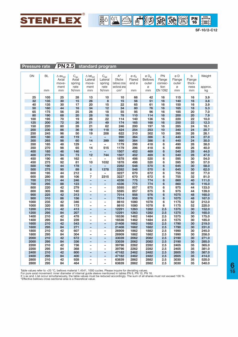
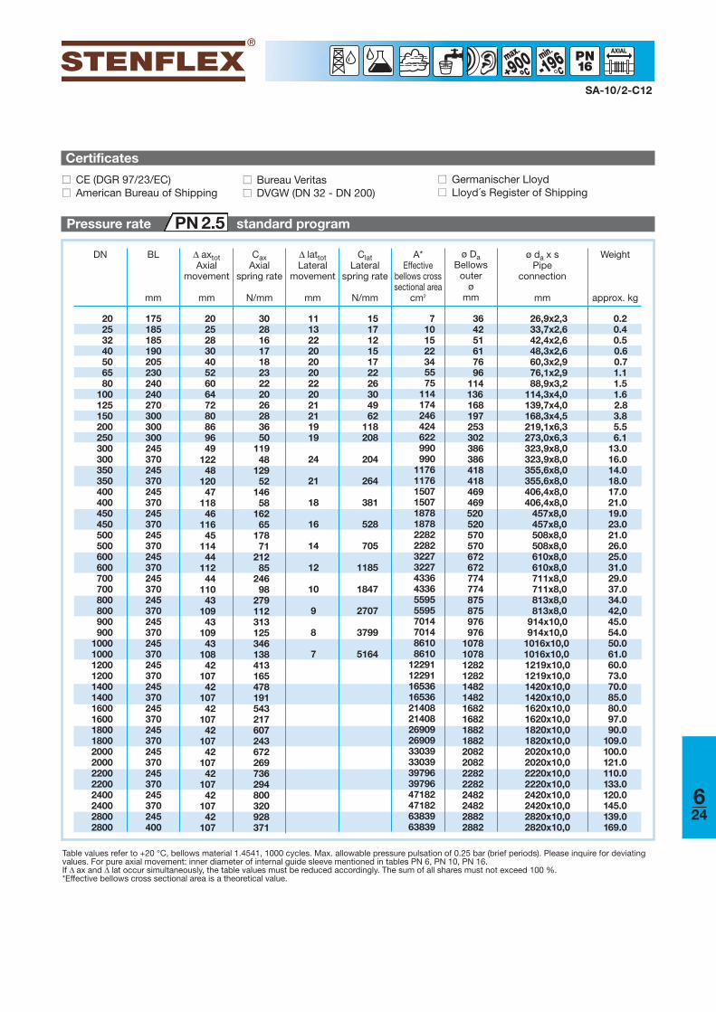
SF-10/2-C12
Table values refer to +20 °C, bellows material 1.4541, 1000 cycles. Please inquire for deviating values.For pure axial movement: inner diameter of internal guide sleeve mentioned in tables PN 6, PN 10, PN 16.If Δ ax and Δ lat occur simultaneously, the table values must be reduced accordingly. The sum of all shares must not exceed 100 %.*Effective bellows cross sectional area is a theoretical value.
900°° -196min
°°DINEN
DN BL
mm
Δ axtotAxial
move-mentmm
CaxAxial
springrate
N/mm
Δ lattotLateralmove-mentmm
ClatLateralspringrate
N/mm
A*Effective
bellows crosssectional area
cm2
ø d4Flaredend ø
mm
ø DaBellows
outer ø
mm
Weight
approx.kg
bFlangethick-nessmm
PNFlange
connec-tion
EN 1092
ø DFlangeouter
ømm
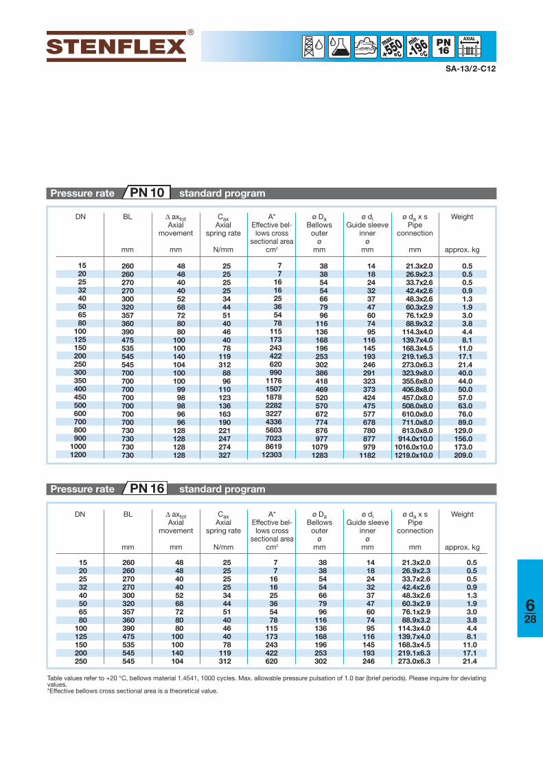
Pressure rate standard programPN 2.5
616
25 105 25 28 13 10 10 68 42 16 115 16 3.932 135 30 15 26 8 15 56 51 16 140 16 3.840 135 30 17 20 15 22 65 61 16 150 16 3.950 160 44 16 34 12 34 80 76 16 165 18 5.365 175 56 25 26 18 55 95 96 16 185 20 7.080 190 68 20 28 18 78 110 114 16 200 20 7.9
100 195 70 19 26 22 114 140 136 16 220 22 10.0125 200 72 26 21 49 174 165 168 16 250 22 12.3150 220 80 28 21 62 246 200 197 16 285 24 16.1200 230 86 36 19 118 424 254 253 10 340 24 20.7250 245 96 50 19 208 622 310 302 10 395 26 26.1300 180 48 119 – – 990 364 386 6 440 24 27.0300 265 98 60 14 399 990 364 386 6 440 24 30.0350 185 48 129 – – 1179 396 418 6 490 26 38.0350 270 98 65 14 515 1179 396 418 6 490 26 40.0400 185 46 146 – – 1507 452 469 6 540 28 44.0400 270 94 73 12 744 1507 452 469 6 540 28 47.0450 190 46 162 – – 1878 498 520 6 595 30 54.0450 275 92 81 10 1032 1878 498 520 6 595 30 57.0500 190 44 178 – – 2282 548 570 6 645 30 58.0500 275 90 89 8 1378 2282 548 570 6 645 30 62.0600 195 44 212 – – 3227 670 672 6 755 32 77.0600 280 88 106 7 2315 3227 670 672 6 755 32 81.0700 210 44 246 – – 4336 775 774 6 860 40 111.0700 295 88 123 – – 4336 775 774 6 860 40 116.0800 220 42 279 – – 5595 857 875 6 975 44 133.0 800 305 86 140 – – 5595 857 875 6 975 44 139.0900 225 42 313 – – 7014 958 976 6 1075 48 160.0 900 310 86 156 – – 7014 958 976 6 1075 48 167.0
1000 235 42 346 – – 8610 1080 1078 6 1175 52 212.0 1000 320 86 173 – – 8610 1080 1078 6 1175 52 220.01200 210 42 413 – – 12291 1263 1282 2.5 1375 30 152.0 1200 295 84 207 – – 12291 1263 1282 2.5 1375 30 160.01400 210 42 478 – – 16536 1462 1484 2.5 1575 30 175.0 1400 295 84 239 – – 16536 1462 1484 2.5 1575 30 185.01600 210 42 543 – – 21408 1662 1682 2.5 1790 30 219.0 1600 295 84 271 – – 21408 1662 1682 2.5 1790 30 231.01800 210 42 607 – – 26909 1862 1882 2.5 1990 30 245.0 1800 295 84 304 – – 26909 1862 1882 2.5 1990 30 258.02000 210 42 672 – – 33039 2062 2082 2.5 2190 30 271.0 2000 295 84 336 – – 33039 2062 2082 2.5 2190 30 285.02200 210 42 736 – – 39796 2262 2282 2.5 2405 35 365.0 2200 295 84 368 – – 39796 2262 2282 2.5 2405 35 381.02400 210 42 800 – – 47182 2462 2482 2.5 2605 35 387.0 2400 295 84 400 – – 47182 2462 2482 2.5 2605 35 414.02800 210 42 928 – – 63839 2862 2882 2.5 3030 35 520.0 2800 295 84 464 – – 63839 2862 2882 2.5 3030 35 540.0
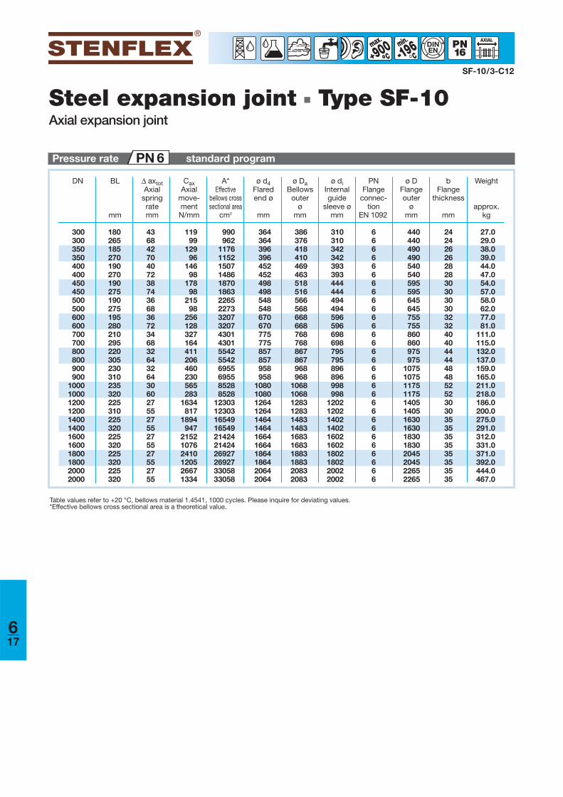
Steel expansion joint ■ Type SF-10Axial expansion joint
DN BL
mm
Δ axtotAxial
springratemm
CaxAxial
move-mentN/mm
A*Effective
bellows crosssectional area
cm2
ø d4Flaredend ø
mm
ø DaBellows
outer ø
mm
Weight
approx.kg
bFlange
thickness
mm
ø DFlangeouter
ømm
ø diInternalguide
sleeve ø mm
PNFlange
connec-tion
EN 1092
Pressure rate standard programPN 6
SF-10/3-C12
900°° -196min
°DINEN
Table values refer to +20 °C, bellows material 1.4541, 1000 cycles. Please inquire for deviating values.*Effective bellows cross sectional area is a theoretical value.
617
180265185270190270190275190275195280210295220305230310235320225310225320225320225320225320
300300350350400400450450500500600600700700800800900900
100010001200120014001400160016001800180020002000
436842704072387436683672346832643264306027552755275527552755
11999
12996
14698
17898
21598
256128327164411206460230565283
1634817
1894947
215210762410120526671334
990962
117611521507148618701863226522733207320743014301554255426955695585288528
12303123031654916549214242142426927269273305833058
364364396396452452498498548548670670775775857857958958
108010801264126414641464166416641864186420642064
386376418410469463518516566568668668768768867867968968
106810681283128314831483168316831883188320832083
310310342342393393444444494494596596698698795795896896998998
1202120214021402160216021802180220022002
440440490490540540595595645645755755860860975975
10751075117511751405140516301630183018302045204522652265
242426262828303030303232404044444848525230303535353535353535
27.029.038.039.044.047.054.057.058.062.077.081.0
111.0115.0132.0137.0159.0165.0211.0218.0186.0200.0275.0291.0312.0331.0371.0392.0444.0467.0
666666666666666666666666666666
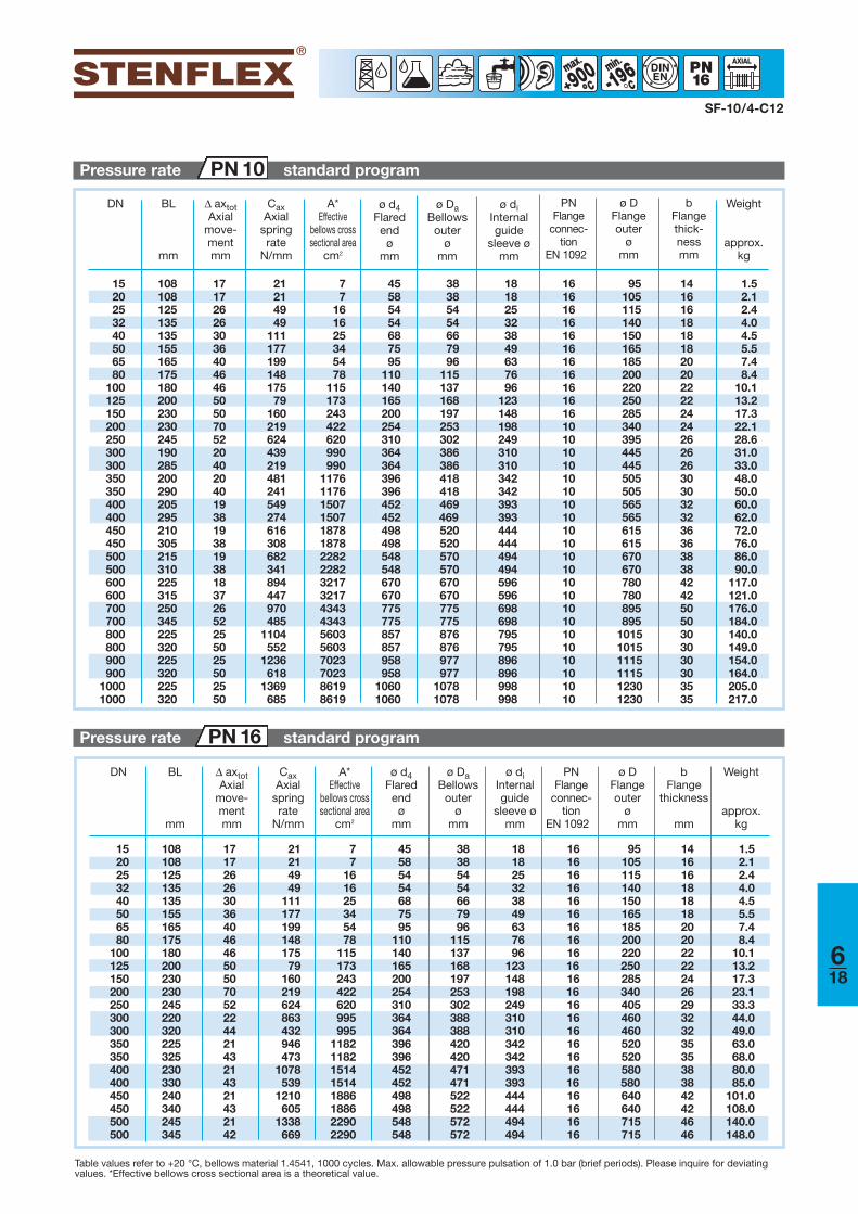
SF-10/4-C12
900°° -196min
°DINEN
Pressure rate standard programPN 10
Table values refer to +20 °C, bellows material 1.4541, 1000 cycles. Max. allowable pressure pulsation of 1.0 bar (brief periods). Please inquire for deviatingvalues. *Effective bellows cross sectional area is a theoretical value.
DN BL
mm
Δ axtotAxial
move-mentmm
CaxAxial
springrate
N/mm
A*Effective
bellows crosssectional area
cm2
ø d4Flaredend ø
mm
ø DaBellows
outer ø
mm
Weight
approx.kg
bFlangethick-nessmm
PNFlange
connec-tion
EN 1092
ø DFlangeouter
ømm
DN BL
mm
Δ axtotAxial
move-mentmm
CaxAxial
springrate
N/mm
A*Effective
bellows crosssectional area
cm2
ø d4Flaredend ø
mm
ø DaBellows
outer ø
mm
Weight
approx.kg
bFlange
thickness
mm
ø DFlangeouter
ømm
ø diInternalguide
sleeve ø mm
PNFlange
connec-tion
EN 1092
Pressure rate standard programPN 16
ø diInternalguide
sleeve ø mm
618
15 108 17 7 45 38 18 16 95 1420 108 17 7 58 38 18 16 105 1625 125 26 16 54 54 25 16 115 1632 135 26 16 54 54 32 16 140 1840 135 30 25 68 66 38 16 150 1850 155 36 34 75 79 49 16 165 1865 165 40 54 95 96 63 16 185 2080 175 46 78 110 115 76 16 200 20
100 180 46 115 140 137 96 16 220 22125 200 50 173 165 168 123 16 250 22150 230 50 243 200 197 148 16 285 24200 230 70 422 254 253 198 10 340 24250 245 52 620 310 302 249 10 395 26300 190 20 990 364 386 310 10 445 26300 285 40 990 364 386 310 10 445 26350 200 20 1176 396 418 342 10 505 30350 290 40 1176 396 418 342 10 505 30400 205 19 1507 452 469 393 10 565 32400 295 38 1507 452 469 393 10 565 32450 210 19 1878 498 520 444 10 615 36 450 305 38 1878 498 520 444 10 615 36500 215 19 2282 548 570 494 10 670 38500 310 38 2282 548 570 494 10 670 38600 225 18 3217 670 670 596 10 780 42600 315 37 3217 670 670 596 10 780 42700 250 26 4343 775 775 698 10 895 50700 345 52 4343 775 775 698 10 895 50800 225 25 5603 857 876 795 10 1015 30 800 320 50 5603 857 876 795 10 1015 30900 225 25 7023 958 977 896 10 1115 30 900 320 50 7023 958 977 896 10 1115 30
1000 225 25 8619 1060 1078 998 10 1230 35 1000 320 50 8619 1060 1078 998 10 1230 35
15 108 17 21 7 45 38 18 16 95 1420 108 17 21 7 58 38 18 16 105 1625 125 26 49 16 54 54 25 16 115 1632 135 26 49 16 54 54 32 16 140 1840 135 30 111 25 68 66 38 16 150 1850 155 36 177 34 75 79 49 16 165 1865 165 40 199 54 95 96 63 16 185 2080 175 46 148 78 110 115 76 16 200 20
100 180 46 175 115 140 137 96 16 220 22125 200 50 79 173 165 168 123 16 250 22150 230 50 160 243 200 197 148 16 285 24200 230 70 219 422 254 253 198 16 340 26250 245 52 624 620 310 302 249 16 405 29300 220 22 863 995 364 388 310 16 460 32300 320 44 432 995 364 388 310 16 460 32350 225 21 946 1182 396 420 342 16 520 35350 325 43 473 1182 396 420 342 16 520 35400 230 21 1078 1514 452 471 393 16 580 38400 330 43 539 1514 452 471 393 16 580 38450 240 21 1210 1886 498 522 444 16 640 42450 340 43 605 1886 498 522 444 16 640 42500 245 21 1338 2290 548 572 494 16 715 46500 345 42 669 2290 548 572 494 16 715 46
21214949
11117719914817579
160219624439219481241549274616308682341894447970485
1104552
1236618
1369685
1.52.12.44.04.55.57.48.4
10.113.217.322.128.631.033.048.050.060.062.072.076.086.090.0
117.0121.0176.0184.0140.0149.0154.0164.0205.0217.0
1.52.12.44.04.55.57.48.4
10.113.217.323.133.344.049.063.068.080.085.0
101.0108.0140.0148.0
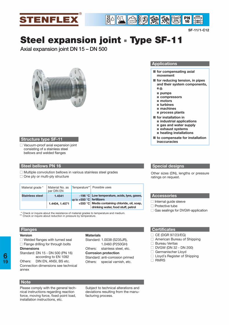
Steel expansion joint ■ Type SF-11Axial expansion joint DN 15 – DN 500
■ for compensating axial movement
■ for reducing tension, in pipesand their system components,e.g. ■ pumps■ compressors■ motors■ turbines■ machines■ process plants
■ for installation in■ industrial applications■ gas and water supply■ exhaust systems■ heating installations
■ to compensate for installationinaccuracies
Applications
-196min
°°550°°
DINEN
Structure type SF-11■■ Vacuum-proof axial expansion joint
consisting of a stainless steel bellows and welded flanges
FlangesVersion■■ Welded flanges with turned seal■■ Flange drilling for through boltsDimensionsStandard: DN 15 - DN 500 (PN 16)
according to EN 1092Others: DIN EN, ANSI, BS etc. Connection dimensions see technicalannex
MaterialsStandard: 1.0038 (S235JR),
1.0460 (P250GH)Others: stainless steel, etc.Corrosion protectionStandard: anti-corrosion primedOthers: special varnish, etc.
Steel bellows PN 16■■ Multiple convolution bellows in various stainless steel grades■■ One ply or multi-ply structure
* Check or inquire about the resistance of material grades to temperature and medium.** Check or inquire about reduction in pressure by temperature.
SF-11/1-C12
Material grade * Material No. asper DIN EN
Possible usesTemperature**
Stainless steel 1.4541
1.4404, 1.4571
-196 °Cup to +550 °C
+550 °C
Low temperature, acids, lyes, gases,fertilizersMedia containing chloride, oil, soap,drinking water, food stuff, petrol
NotePlease comply with the general tech-nical instructions regarding reactionforce, moving force, fixed point load,installation instructions, etc.
Subject to technical alterations anddeviations resulting from the manu-facturing process.
Special designs
Other sizes (DN), lengths or pressureratings on request.
Accessories■■ Internal guide sleeve■■ Protective tube■■ Gas sealings for DVGW-application
Certificates■■ CE (DGR 97/23/EG)■■ American Bureau of Shipping■■ Bureau Veritas■■ DVGW (DN 32 - DN 200)■■ Germanischer Lloyd■■ Lloyd´s Register of Shipping■■ RMRS
619
Versions
Type SF-11
-196min
°°550°°
DINEN
SF-11/2-C12
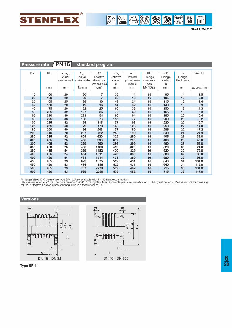
For larger sizes (DN) please see type SF-16. Also available with PN 10 flange connection.Table values refer to +20 °C, bellows material 1.4541, 1000 cycles. Max. allowable pressure pulsation of 1.6 bar (brief periods). Please inquire for deviatingvalues. *Effective bellows cross sectional area is a theoretical value.
DN BL
mm
Δ axtotAxial
movement
mm
CaxAxial
spring rate
N/mm
A*Effective
bellows crosssectional area
cm2
ø DaBellows
outerø
mm
ø diInternal
guide sleeveinner ømm
Weight
approx. kg
bFlange
thickness
mm
PNFlange
connec-tion
EN 1092
ø DFlangeouter
ømm
Pressure rate standard programPN 16
DN 40 - DN 500DN 15 - DN 32 620
15 100 20 30 7 36 14 16 95 1420 100 20 30 7 36 18 16 105 1625 105 25 28 10 42 24 16 115 1632 150 20 49 16 54 32 16 140 1840 175 26 132 25 66 38 16 150 1850 205 32 197 36 79 49 16 165 1865 210 36 221 54 96 64 16 185 2080 225 38 188 78 115 77 16 200 20
100 235 42 175 115 137 96 16 220 20125 265 50 79 173 168 123 16 250 22150 290 50 156 243 197 150 16 285 22200 310 70 237 422 253 199 16 340 24250 335 52 624 620 302 250 16 405 26300 255 25 455 993 387 299 16 460 28300 405 52 379 990 386 299 16 460 28350 260 25 496 1180 419 329 16 520 30350 415 54 379 1182 420 329 16 520 30400 265 24 564 1511 470 380 16 580 32400 420 54 431 1514 471 380 16 580 32450 265 23 693 1875 519 431 16 640 34450 420 53 484 1886 522 431 16 640 34500 265 23 767 2278 569 482 16 715 36500 420 53 535 2290 572 482 16 715 36
1.52.02.43.94.35.36.48.29.7
14.017.224.936.049.056.071.079.088.098.0
104.0115.0134.0147.0
Versions
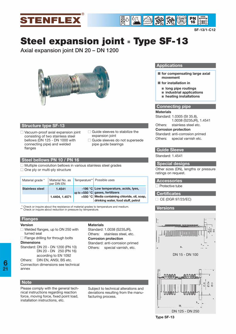
Steel expansion joint ■ Type SF-13Axial expansion joint DN 20 – DN 1200
■ for compensating large axialmovement
■ for installation in
■ long pipe routings■ industrial applications■ heating installations
Applications
SF-13/1-C12
550°° -196min
°°DINEN
Structure type SF-13■■ Vacuum-proof axial expansion joint
consisting of two stainless steel bellows (DN 125 - DN 1000 withconnecting pipe) and weldedflanges
FlangesVersion■■ Welded flanges, up to DN 250 with
turned seal■■ Flange drilling for through boltsDimensionsStandard: DN 20 - DN 1200 (PN 10)
DN 20 - DN 250 (PN 16)according to EN 1092
Others: DIN EN, ANSI, BS etc. Connection dimensions see technicalannex
MaterialsStandard: 1.0038 (S235JR), Others: stainless steel, etc.Corrosion protectionStandard: anti-corrosion primedOthers: special varnish, etc.
Steel bellows PN 10 / PN 16■■ Multiple convolution bellows in various stainless steel grades■■ One ply or multi-ply structure
* Check or inquire about the resistance of material grades to temperature and medium.** Check or inquire about reduction in pressure by temperature.
■■ Guide sleeves to stabilize the expansion joint
■■ Guide sleeves do not supersedepipe guide bearings
Accessories■■ Protective tube
Certificates■■ CE (DGR 97/23/EC)
Connecting pipeMaterialsStandard: 1.0305 (St 35.8),
1.0038 (S235JR), 1.4541Others: stainless steel etc.Corrosion protectionStandard: anti-corrosion primedOthers: special varnish etc.
Special designsOther sizes (DN), lengths or pressureratings on request.
Material grade * Material No. asper DIN EN
Possible usesTemperature**
Stainless steel 1.4541
1.4404, 1.4571
-196 °Cup to +550 °C
+550 °C
Low temperature, acids, lyes, gases, fertilizersMedia containing chloride, oil, soap,drinking water, food stuff, petrol
NotePlease comply with the general tech-nical instructions regarding reactionforce, moving force, fixed point load,installation instructions, etc.
Subject to technical alterations anddeviations resulting from the manu-facturing process.
Guide SleeveStandard: 1.4541
621
DN 15 - DN 100
DN 125 - DN 250
Type SF-13
SF-13/2-C12
550°° -196min
°°DINEN
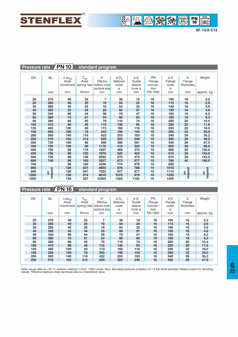
Table values refer to +20 °C, bellows material 1.4541, 1000 cycles. Max. allowable pressure pulsation of 1.0 bar (brief periods). Please inquire for deviatingvalues. *Effective bellows cross sectional area is a theoretical value.
DN BL
mm
Pressure rate standard programPN 16
Δ axtotAxial
movement
mm
CaxAxial
spring rate
N/mm
A*Effective
bellows crosssectional area
cm2
ø DaBellows
outer ø
mm
ø diGuidesleeveinner ø
mm
Weight
approx. kg
bFlange
thickness
mm
PNFlange
connec-tion
EN 1092
ø DFlangeouter
ømm
Pressure rate standard programPN 10
622
20 270 48 25 7 38 18 16 105 16 2.225 285 40 25 16 54 24 16 115 16 2.932 285 40 25 16 54 32 16 140 16 3.940 320 52 34 25 66 37 16 150 16 4.650 340 68 44 36 79 47 16 165 18 6.265 380 72 51 54 96 60 16 185 18 8.380 380 80 40 78 116 74 16 200 20 10.4
100 410 80 46 115 136 95 16 220 20 11.6125 495 100 40 173 168 116 16 250 22 18.0150 555 100 78 243 196 145 16 285 22 23.0200 565 140 119 422 253 193 10 340 26 35.2250 570 104 312 620 302 246 10 395 29 46.0300 720 100 88 990 386 291 10 445 26 67.0350 720 100 96 1176 418 323 10 505 30 85.0400 720 99 110 1507 469 373 10 565 32 105.0450 730 98 123 1878 520 424 10 615 36 124.0500 730 98 136 2282 570 475 10 670 38 143.0600 740 96 163 3227 672 577 10 780 42 185.0700 96 190 4336 774 678 10 895 800 128 221 5603 876 780 10 1015 900 128 247 7023 977 877 10 1115
1000 128 274 8619 1079 979 10 12301200 128 327 12303 1283 1182 10 1455
20 270 48 25 7 38 18 16 105 1625 285 40 25 16 54 24 16 115 1632 285 40 25 16 54 32 16 140 1640 320 52 34 25 66 37 16 150 1650 340 68 44 36 79 47 16 165 1865 380 72 51 54 96 60 16 185 1880 380 80 40 78 116 74 16 200 20
100 410 80 46 115 136 95 16 220 20125 495 100 40 173 168 116 16 250 22150 555 100 78 243 196 145 16 285 22200 565 140 119 422 253 193 16 340 26250 570 104 312 620 302 246 16 405 29
on
req
uest
on
req
uest
2.22.93.94.66.28.3
10.411.618.023.035.247.9
on
req
uest
DN BL
mm
Δ axtotAxial
movement
mm
CaxAxial
spring rate
N/mm
A*Effective
bellows crosssectional area
cm2
ø DaBellows
outer ø
mm
ø diGuidesleeveinner ø
mm
Weight
approx. kg
bFlange
thickness
mm
PNFlange
connec-tion
EN 1092
ø DFlangeouter
ømm
Versions
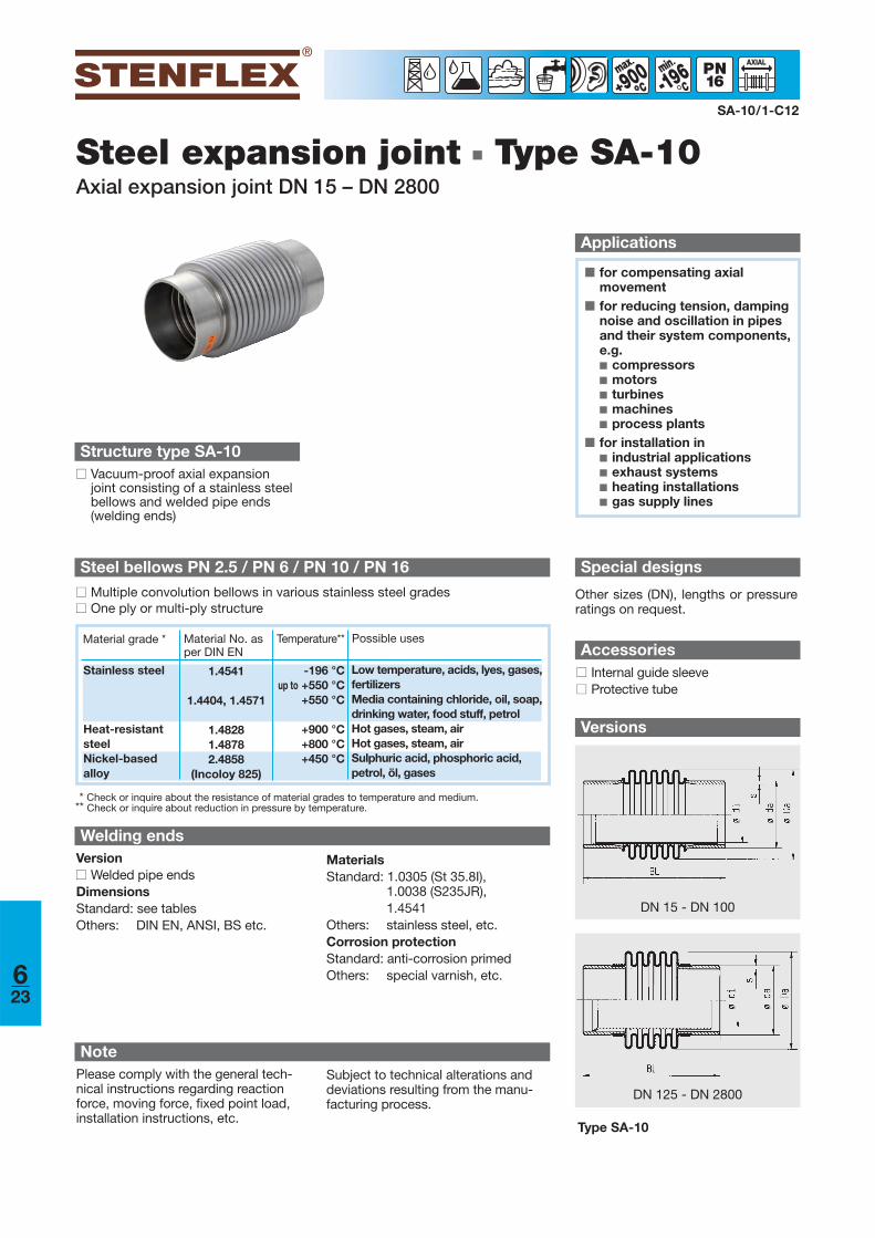
Steel expansion joint ■ Type SA-10Axial expansion joint DN 15 – DN 2800
■ for compensating axial movement
■ for reducing tension, dampingnoise and oscillation in pipesand their system components,e.g. ■ compressors■ motors■ turbines■ machines■ process plants
■ for installation in■ industrial applications■ exhaust systems■ heating installations■ gas supply lines
Applications
SA-10/1-C12
-196min
°
DN 125 - DN 2800
DN 15 - DN 100
Structure type SA-10■■ Vacuum-proof axial expansion
joint consisting of a stainless steel bellows and welded pipe ends(welding ends)
Welding endsVersion■■ Welded pipe endsDimensionsStandard: see tablesOthers: DIN EN, ANSI, BS etc.
MaterialsStandard: 1.0305 (St 35.8I),
1.0038 (S235JR), 1.4541
Others: stainless steel, etc.Corrosion protectionStandard: anti-corrosion primedOthers: special varnish, etc.
Steel bellows PN 2.5 / PN 6 / PN 10 / PN 16
Accessories■■ Internal guide sleeve■■ Protective tube
900°°
Type SA-10
Special designs
Other sizes (DN), lengths or pressureratings on request.
■■ Multiple convolution bellows in various stainless steel grades■■ One ply or multi-ply structure
Material grade * Material No. asper DIN EN
Possible usesTemperature**
Stainless steel
Heat-resistantsteelNickel-based alloy
1.4541
1.4404, 1.4571
1.48281.48782.4858
(Incoloy 825)
-196 °Cup to +550 °C
+550 °C
+900 °C+800 °C+450 °C
Low temperature, acids, lyes, gases,fertilizersMedia containing chloride, oil, soap,drinking water, food stuff, petrolHot gases, steam, airHot gases, steam, airSulphuric acid, phosphoric acid,petrol, öl, gases
* Check or inquire about the resistance of material grades to temperature and medium.** Check or inquire about reduction in pressure by temperature.
NotePlease comply with the general tech-nical instructions regarding reactionforce, moving force, fixed point load,installation instructions, etc.
Subject to technical alterations anddeviations resulting from the manu-facturing process.
623
DN BL
mm
Δ axtotAxial
movement
mm
CaxAxial
spring rate
N/mm
Δ lattotLateral
movement
mm
ClatLateral
spring rate
N/mm
A*Effective
bellows crosssectional area
cm2
Weight
approx. kg
ø da x sPipe
connection
mm
Pressure rate standard programPN 2.5
Certificates
■■ Bureau Veritas■■ DVGW (DN 32 - DN 200)
SA-10/2-C12
-196min
°
Table values refer to +20 °C, bellows material 1.4541, 1000 cycles. Max. allowable pressure pulsation of 0.25 bar (brief periods). Please inquire for deviatingvalues. For pure axial movement: inner diameter of internal guide sleeve mentioned in tables PN 6, PN 10, PN 16.If Δ ax and Δ lat occur simultaneously, the table values must be reduced accordingly. The sum of all shares must not exceed 100 %.*Effective bellows cross sectional area is a theoretical value.
■■ CE (DGR 97/23/EC)■■ American Bureau of Shipping
ø DaBellows
outerø
mm
900°°
■■ Germanischer Lloyd■■ Lloyd´s Register of Shipping
624
20 175 20 30 11 15 7 36 26,9x2,3 0.225 185 25 28 13 17 10 42 33,7x2,6 0.432 185 28 16 22 12 15 51 42,4x2,6 0.540 190 30 17 20 15 22 61 48,3x2,6 0.650 205 40 18 20 17 34 76 60,3x2,9 0.765 230 52 23 20 22 96 76,1x2,9 1.180 240 60 22 22 26 114 88,9x3,2 1.5
100 240 64 20 20 30 136 114,3x4,0 1.6125 270 72 26 21 49 168 139,7x4,0 2.8150 300 80 28 21 62 197 168,3x4,5 3.8200 300 86 36 19 118 253 219,1x6,3 5.5250 300 96 50 19 208 302 273,0x6,3 6.1300 245 49 119 386 323,9x8,0 13.0300 370 24 204 386 323,9x8,0 16.0350 245 418 355,6x8,0 14.0350 370 21 264 418 355,6x8,0 18.0400 245 469 406,4x8,0 17.0400 370 18 381 469 406,4x8,0 21.0450 245 520 457x8,0 19.0450 370 16 528 520 457x8,0 23.0500 245 570 508x8,0 21.0500 370 14 705 570 508x8,0 26.0600 245 672 610x8,0 25.0600 370 12 1185 672 610x8,0 31.0700 245 774 711x8,0 29.0700 370 10 1847 774 711x8,0 37.0800 245 875 813x8,0 34.0800 370 9 2707 875 813x8,0 42,0900 245 976 914x10,0 45.0900 370 8 3799 976 914x10,0 54.0
1000 245 1078 1016x10,0 50.01000 370 7 5164 1078 1016x10,0 61.01200 245 1282 1219x10,0 60.01200 370 1282 1219x10,0 73.01400 245 1482 1420x10,0 70.01400 370 1482 1420x10,0 85.01600 245 1682 1620x10,0 80.01600 370 1682 1620x10,0 97.01800 245 1882 1820x10,0 90.01800 370 1882 1820x10,0 109.02000 245 2082 2020x10,0 100.02000 370 2082 2020x10,0 121.02200 245 2282 2220x10,0 110.02200 370 2282 2220x10,0 133.02400 245 2482 2420x10,0 120.02400 370 2482 2420x10,0 145.02800 245 2882 2820x10,0 139.02800 400 2882 2820x10,0 169.0
12248
12047
11846
11645
11444
11244
11043
10943
10943
10842
10742
10742
10742
10742
10742
10742
10742
107
4812952
14658
16265
17871
21285
24698
279112313125346138413165478191543217607243672269736294800320928371
5575
114174246424622990990
117611761507150718781878228222823227322743364336559555957014701486108610
12291122911653616536214082140826909269093303933039397963979647182471826383963839
DN BL
mm
Δ axtotAxial move-
ment
mm
CaxAxial spring
rate
N/mm
A*Effective
bellows crosssectional area
cm2
Weight
approx. kg
ø diGuide sleeve
innerø
mm
ø da x sPipe
connection
mm
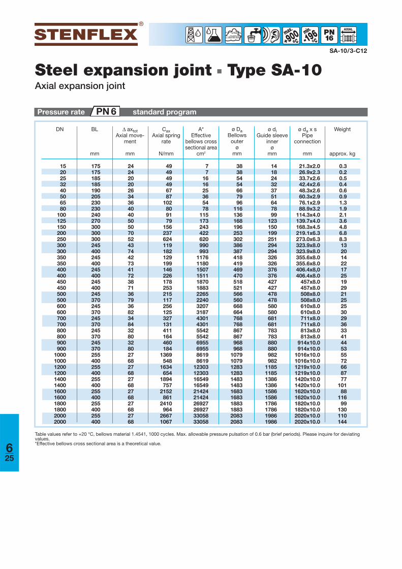
Pressure rate standard programPN 6
Steel expansion joint ■ Type SA-10Axial expansion joint
SA-10/3-C12
ø DaBellows
outerø
mm
Table values refer to +20 °C, bellows material 1.4541, 1000 cycles. Max. allowable pressure pulsation of 0.6 bar (brief periods). Please inquire for deviatingvalues.*Effective bellows cross sectional area is a theoretical value.
-196min
°°900°°
625
1520253240506580
100125150200250300300350350400400450450500500600600700700800800900900
100010001200120014001400160016001800180020002000
175175185185190205230230240270300300300245400245400245400245400245370245370245370245370245370255400255400255400255400255400255400
24242020263436404050507052437442734172387136793682348432803280276827682768276827682768
494949496787
102809179
156237624119182129199146226178253215117256125327131411164460184
1369548
1634654
1894757
2152861
2410964
26671067
77
161625365478
115173243422620990993
117611801507151118701883226522403207318743014301554255426955695586198619
12303123031654916549214242142426927269273305833058
38385454667996
116136168196253302386387418419469470518521566560668664768768867867968968
107910791283128314831483168316831883188320832083
141824323751647899
123150199251294294326326376376427427478478580580681681783783880880982982
1185118513861386158615861786178619861986
21.3x2.026.9x2.333.7x2.642.4x2.648.3x2.660.3x2.976.1x2.988.9x3.2
114.3x4.0139.7x4.0168.3x4.5219.1x6.3273.0x6.3323.9x8.0323.9x8.0355.6x8.0355.6x8.0406.4x8,0406.4x8.0
457x8.0457x8.0508x8.0508x8.0610x8.0610x8.0711x8.0711x8.0813x8.0813x8.0
914x10.0914x10.0
1016x10.01016x10.01219x10.01219x10.01420x10.01420x10.01620x10.01620x10.01820x10.01820x10.02020x10.02020x10.0
0.30.20.50.40.60.91.31.92.13.64.86.88.31320142217251929212525302936334144535572668777
10188
11699
130110144
DN BL
mm
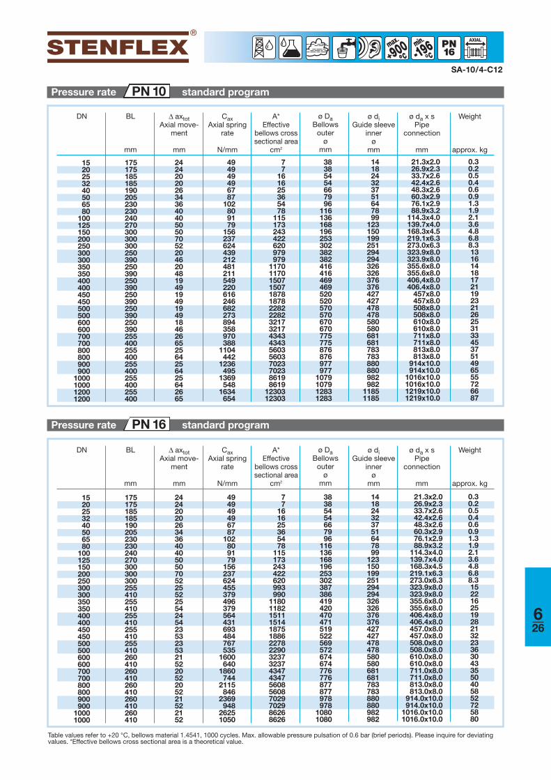
Table values refer to +20 °C, bellows material 1.4541, 1000 cycles. Max. allowable pressure pulsation of 0.6 bar (brief periods). Please inquire for deviatingvalues. *Effective bellows cross sectional area is a theoretical value.
Pressure rate standard programPN 16
SA-10/4-C12
DN BL
mm
Pressure rate standard programPN 10
-196min
°°900°°
Δ axtotAxial move-
ment
mm
CaxAxial spring
rate
N/mm
A*Effective
bellows crosssectional area
cm2
Weight
approx. kg
ø diGuide sleeve
innerø
mm
ø da x sPipe
connection
mm
ø DaBellows
outerø
mm
Δ axtotAxial move-
ment
mm
CaxAxial spring
rate
N/mm
A*Effective
bellows crosssectional area
cm2
Weight
approx. kg
ø diGuide sleeve
innerø
mm
ø da x sPipe
connection
mm
ø DaBellows
outerø
mm
626
1520253240506580
100125150200250300300350350400400450450500500600600700700800800900900
1000100012001200
175175185185190205230230240270300300300250390250390250390250390250390250390255400255400255400255400255400
2424202026343640405050705220462048194919491949184626652564256425642665
494949496787
102809179
156237624439212481211549220616246682273894358970388
1104442
1236495
1369548
1634654
77
161625365478
115173243422620979979
117011701507150718781878228222823217321743434343560356037023702386198619
1230312303
38385454667996
116136168196253302382382416416469469520520570570670670775775876876977977
1079107912831283
141824323751647899
123150199251294294326326376376427427478478580580681681783783880880982982
11851185
21.3x2.026.9x2.333.7x2.642.4x2.648.3x2.660.3x2.976.1x2.988.9x3.2
114.3x4.0139.7x4.0168.3x4.5219.1x6.3273.0x6.3323.9x8.0323.9x8.0355.6x8.0355.6x8.0406,4x8.0406.4x8.0
457x8.0457x8.0508x8.0508x8.0610x8.0610x8.0711x8.0711x8.0813x8.0813x8.0
914x10.0914x10.0
1016x10.01016x10.01219x10.01219x10.0
0.30.20.50.40.60.91.31.92.13.64.86.88.313161418172119232126253133453751496555726687
1520253240506580
100125150200250300300350350400400450450500500600600700700800800900900
10001000
175175185185190205230230240270300300300255410255410255410255410255410260410260410260410260410260410
242420202634364040505070522552255424542353235321522052205221522152
494949496787
102809179
156237624455379496379564431693484767535
1600640
1860744
2115846
2369948
26251050
77
161625365478
115173243422620993990
118011821511151418751886227822903237323743474347560856087029702986268626
38385454667996
116136168196253302387386419420470471519522569572674674776776877877978978
10801080
141824323751647899
123150199251294294326326376376427427478478580580681681783783880880982982
21.3x2.026.9x2.333.7x2.642.4x2.648.3x2.660.3x2.976.1x2.988.9x3.2
114.3x4.0139.7x4.0168.3x4.5219.1x6.3273.0x6.3323.9x8.0323.9x8.0355.6x8.0355.6x8.0406.4x8.0406.4x8.0457.0x8.0457.0x8.0508.0x8.0508.0x8.0610.0x8.0610.0x8.0711.0x8.0711.0x8.0813.0x8.0813.0x8.0
914.0x10.0914.0x10.0
1016.0x10.01016.0x10.0
0.30.20.50.40.60.91.31.92.13.64.86.88.31522162519282132233630433550405852725880
Versions
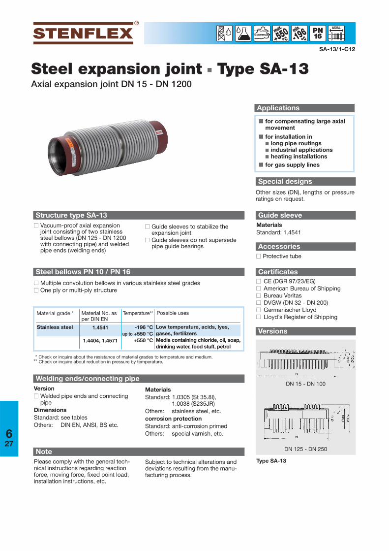
Steel expansion joint ■ Type SA-13Axial expansion joint DN 15 - DN 1200
■ for compensating large axialmovement
■ for installation in■ long pipe routings■ industrial applications■ heating installations
■ for gas supply lines
Applications
SA-13/1-C12
-196min
°°550°°
Structure type SA-13
■■ Guide sleeves to stabilize the expansion joint
■■ Guide sleeves do not supersedepipe guide bearings
Welding ends/connecting pipeVersion■■ Welded pipe ends and connecting
pipeDimensionsStandard: see tablesOthers: DIN EN, ANSI, BS etc.
MaterialsStandard: 1.0305 (St 35.8I),
1.0038 (S235JR)Others: stainless steel, etc.corrosion protectionStandard: anti-corrosion primedOthers: special varnish, etc.
Steel bellows PN 10 / PN 16
■■ Multiple convolution bellows in various stainless steel grades■■ One ply or multi-ply structure
■■ Vacuum-proof axial expansionjoint consisting of two stainlesssteel bellows (DN 125 - DN 1200with connecting pipe) and weldedpipe ends (welding ends)
Accessories■■ Protective tube
Certificates■■ CE (DGR 97/23/EG)■■ American Bureau of Shipping■■ Bureau Veritas■■ DVGW (DN 32 - DN 200)■■ Germanischer Lloyd■■ Lloyd´s Register of Shipping
Special designsOther sizes (DN), lengths or pressureratings on request.
Guide sleeveMaterialsStandard: 1.4541
* Check or inquire about the resistance of material grades to temperature and medium.** Check or inquire about reduction in pressure by temperature.
Material grade * Material No. asper DIN EN
Possible usesTemperature**
Stainless steel 1.4541
1.4404, 1.4571
-196 °Cup to +550 °C
+550 °C
Low temperature, acids, lyes, gases, fertilizersMedia containing chloride, oil, soap,drinking water, food stuff, petrol
NotePlease comply with the general tech-nical instructions regarding reactionforce, moving force, fixed point load,installation instructions, etc.
Subject to technical alterations anddeviations resulting from the manu-facturing process.
627
DN 125 - DN 250
DN 15 - DN 100
Type SA-13
-196min
°°550°°
SA-13/2-C12
DN BL
mm
DN BL
mm
Δ axtotAxial
movement
mm
CaxAxial
spring rate
N/mm
A*Effective bel-lows cross
sectional areacm2
ø DaBellows
outerø
mm
Weight
approx. kg
ø diGuide sleeve
innerø
mm
ø da x sPipe
connection
mm
Δ axtotAxial
movement
mm
CaxAxial
spring rate
N/mm
A*Effective bel-lows cross
sectional areacm2
ø DaBellows
outerø
mm
Weight
approx. kg
ø diGuide sleeve
innerø
mm
ø da x sPipe
connection
mm
Table values refer to +20 °C, bellows material 1.4541, 1000 cycles. Max. allowable pressure pulsation of 1.0 bar (brief periods). Please inquire for deviatingvalues. *Effective bellows cross sectional area is a theoretical value.
Pressure rate standard programPN 16
Pressure rate standard programPN 10
628
1520253240506580
100125150200250300350400450500600700800900
10001200
260260270270300320357360390475535545545700700700700700700700730730730730
484840405268728080
1001001401041001009998989696
128128128128
2525252534445140464078
1193128896
110123136163190221247274327
77
161625365478
115173243422620990
117615071878228232274336560370238619
12303
38385454667996
116136168196253302386418469520570672774876977
10791283
141824323747607495
116145193246291323373424475577678780877979
1182
21.3x2.026.9x2.333.7x2.642.4x2.648.3x2.660.3x2.976.1x2.988.9x3.2
114.3x4.0139.7x4.0168.3x4.5219.1x6.3273.0x6.3323.9x8.0355.6x8.0406.8x8.0457.0x8.0508.0x8.0610.0x8.0711.0x8.0813.0x8.0
914.0x10.01016.0x10.01219.0x10.0
0.50.50.50.91.31.93.03.84.48.1
11.017.121.440.044.050.057.063.076.089.0
129.0156.0173.0209.0
1520253240506580
100125150200250
260260270270300320357360390475535545545
484840405268728080
100100140104
2525252534445140464078
119312
38385454667996
116136168196253302
141824323747607495
116145193246
77
161625365478
115173243422620
0.50.50.50.91.31.93.03.84.48.1
11.017.121.4
21.3x2.026.9x2.333.7x2.642.4x2.648.3x2.660.3x2.976.1x2.988.9x3.2
114.3x4.0139.7x4.0168.3x4.5219.1x6.3273.0x6.3

Steel expansion joint ■ Type SG-10Axial expansion joint DN 15 – DN 50
Versions
■ for compensating axial movement
■ for reducing tension, in pipesand their system components,e.g.■ pumps■ compressors■ motors■ turbines■ machines
■ to compensate for installationinaccuracies
■ for installation in■ heating installations■ drinking water systems
■ for pipe systems of stainless orunalloyd steel
■ for copper or plastic pipes■ for pressfitting systems
Applications
SG-10/C12
-196min
°550° ISO
152025324050
125130145185200225
242420202634
494949498787
383854546678
R 1/2”R 3/4”R 1”R 1 1/4”R 1 1/2”R 2”
7.07.0
16.016.025.035.0
0.250.250.520.540.801.20
131517191924
DN BL
mm
Δ axtotAxial
move-mentmm
CaxAxial
springrate
N/mm
A*Effective
bellows crosssectional area
cm2
Weight
approx.kg
LLength of
thread
mm
D1Male
thread ø
inch
Structure type SG-10■■ Vacuum-proof axial expansion
joint consisting of a stainless steel bellows and threaded connectionparts
Table values refer to +20 °C, bellows material 1.4541, 1000 cycles. Max. allowable pressure pulsationof 1.6 bar (brief periods). Please inquire for deviating values.*Effective bellows cross sectional area is a theoretical value.
Pressure rate standard programPN 16
Threaded connection partsVersion■■ Male threadDimensionsStandard: R 1/2“ – R 2“ ISO 7-1
(DIN 2999)
MaterialsStandard: 1.4541Others: stainless steel
Steel bellows PN 16■■ Multiple convolution bellows in various stainless steel grades■■ One ply structure
■■ Connection parts with hexagon insert bit and male thread
Certificates■■ CE (DGR 97/23/EC)
ø DaBellows
outerø
mm
SWWidthacross
mm
Type SG-10
DN 15 - DN 25
DN 32 - DN 50
323246---
* Check or inquire about the resistance of material grades to temperature and medium.** Check or inquire about reduction in pressure by temperature.
Material grade * Material No. asper DIN EN
Possible usesTemperature**
Stainless steel 1.4541
1.4404, 1.4571
-196 °Cup to +550 °C
+550 °C
Low temperature, acids, lyes, gases, fertilizersMedia containing chloride, oil, soap,drinking water, food stuff, petrol
NotePlease comply with the general tech-nical instructions regarding reactionforce, moving force, fixed point load,installation instructions, etc.
Subject to technical alterations anddeviations resulting from the manu-facturing process.
629

Version
Steel expansion joint ■ Type SG-11Axial expansion joint DN 15 – DN 50
■ for compensating axial movement
■ for reducing tension, in pipesand their system components,e.g. ■ pumps■ compressors■ motors■ turbines■ machines
■ to compensate for installationinaccuracies
■ for installation in■ exhaust systems■ heating installations
■ gas supply lines
Applications
SG-11/C12
350° ISO
152025324050
130135150158154161
185190212224226245
242426303036
283049
111111177
363654666679
Rp 1/2”Rp 3/4”Rp 1”Rp 1 1/4”Rp 1 1/2”Rp 2”
G 1”G 1 1/4”G 1 1/2”G 2”G 2 1/4”G 2 3/4”
57
16252535
253138485366
384753667390
0.50.80.91.31.72.6
DN BL
mm
GL
mm
Δ axtotAxial
movement
mm
CaxAxial
spring rate
N/mm
A*Effective
bellows crosssectional area
cm2
Weight
approx.kg
ø D3Unionnut ø
inch
Width acrossSW 1
mm
SW 2
mm
ø D2Female thread
øinch
Table values refer to +20 °C, bellows material 1.4541, 1000 cycles. Max. allowable pressure pulsation of 1.6 bar (brief periods). Please inquire for deviatingvalues.*Effective bellows cross sectional area is a theoretical value.
Structure type SG-11■■ Bellows with flared ends, connec-
tion parts with union nut and flatpacking
■■ Connection parts with femalethread
Pressure rate standard programPN 16
■■ Vacuum-proof axial expansion jointconsisting of a stainless steel bellows and threaded connectionparts
Threaded connection partsVersion■■ Female thread■■ Union nut with female thread acc.
ISO 228-1DimensionsStandard: Female thread Rp 1/2“
- Rp 2“ acc. ISO 7-1 (DIN 2999)
MaterialsStandard: GJMW-400-5
(malleable casting)Corrosion protectionStandard: electrogavanized
Steel bellows PN 16■■ Multiple convolution bellows in various stainless steel grades■■ One ply structure
Certificates■■ CE (DGR 97/23/EG)■■ DVGW (DN 25 -DN 50)
ø DaBellows
outer ø
mm
Type SG-11
* Check or inquire about the resistance of material grades to temperature and medium.** Check or inquire about reduction in pressure by temperature.
Material grade * Material No. asper DIN EN
Possible usesTemperature**
Stainless steel 1.4541
1.4404, 1.4571
-196 °Cup to +550 °C
+550 °C
Low temperature, acids, lyes, gases, fertilizersMedia containing chloride, oil, soap,drinking water, food stuff, petrol
NotePlease comply with the general tech-nical instructions regarding reactionforce, moving force, fixed point load,installation instructions, etc.
Subject to technical alterations anddeviations resulting from the manu-facturing process.
630
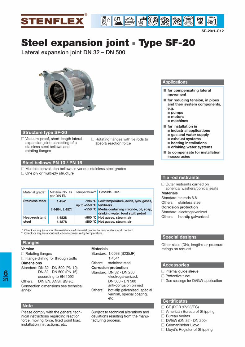
Steel expansion joint ■ Type SF-20Lateral expansion joint DN 32 – DN 500
SF-20/1-C12
-196min
°DINEN
Structure type SF-20■■ Rotating flanges with tie rods to
absorb reaction force
FlangesVersion■■ Rotating flanges■■ Flange drilling for through boltsDimensionsStandard: DN 32 - DN 500 (PN 10)
DN 32 - DN 500 (PN 16)according to EN 1092
Others: DIN EN, ANSI, BS etc. Connection dimensions see technicalannex
MaterialsStandard: 1.0038 (S235JR),
1.4541Others: stainless steelCorrosion protectionStandard: DN 32 - DN 250
electrogalvanized, DN 300 - DN 500 anti-corrosion primed
Others: hot-dip galvanized, specialvarnish, special coating,etc.
Steel bellows PN 10 / PN 16■■ Multiple convolution bellows in various stainless steel grades■■ One ply or multi-ply structure
■■ Vacuum-proof, short-length lateralexpansion joint, consisting of astainless steel bellows and rotating flanges
Accessories■■ Internal guide sleeve■■ Protective tube■■ Gas sealings for DVGW-application
Certificates■■ CE (DGR 97/23/EG)■■ American Bureau of Shipping■■ Bureau Veritas■■ DVGW (DN 32 - DN 200)■■ Germanischer Lloyd■■ Lloyd´s Register of Shipping
Tie rod restraints■■ Outer restraints carried on
spherical washers/conical seats MaterialsStandard: tie rods 8.8 Others: stainless steelCorrosion protectionStandard: electrogalvanizedOthers: hot-dip galvanized
900°°
■ for compensating lateralmovement
■ for reducing tension, in pipesand their system components,e.g. ■ pumps■ motors■ machines
■ for installation in■ industrial applications■ gas and water supply■ exhaust systems■ heating installations■ drinking water systems
■ to compensate for installationinaccuracies
Applications
Material grade* Material No. asper DIN EN
Possible usesTemperature**
Stainless steel
Heat-resistantsteel
1.4541
1.4404, 1.4571
1.48281.4878
-196 °Cup to +550 °C
+550 °C
+900 °C+800 °C
Low temperature, acids, lyes, gases,fertilizersMedia containing chloride, oil, soap,drinking water, food stuff, petrolHot gases, steam, airHot gases, steam, air
* Check or inquire about the resistance of material grades to temperature and medium.** Check or inquire about reduction in pressure by temperature.
Special designs
Other sizes (DN), lengths or pressureratings on request.
NotePlease comply with the general tech-nical instructions regarding reactionforce, moving force, fixed point load,installation instructions, etc.
Subject to technical alterations anddeviations resulting from the manu-facturing process.
631
Version
SF-20/2-C12
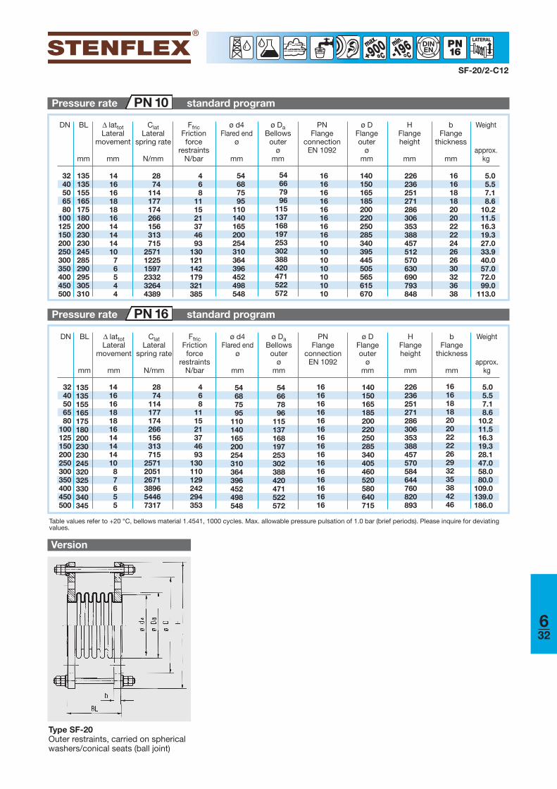
Table values refer to +20 °C, bellows material 1.4541, 1000 cycles. Max. allowable pressure pulsation of 1.0 bar (brief periods). Please inquire for deviatingvalues.
DN BL
mm
Δ lattotLateral
movement
mm
ClatLateral
spring rate
N/mm
FfricFrictionforce
restraintsN/bar
ø DaBellows
outerø
mm
ø d4Flared end
ø
mm
Weight
approx.kg
bFlange
thickness
mm
PNFlange
connection EN 1092
ø DFlangeouter
ømm
HFlangeheight
mm
Type SF-20Outer restraints, carried on sphericalwashers/conical seats (ball joint)
Pressure rate standard programPN 16
Pressure rate standard programPN 10
-196min
°°DINEN900
°°
632
3240506580
100125150200250300350400450500
1416161818161414141087655
2874
114177174266156313715
257120512671389654467317
468
111521374693
130110129242294353
226236251271286306353388457570584644760820893
5.05.57.18.6
10.211.516.319.328.147.058.080.0
109.0139.0186.0
3240506580
100125150200250300350400450500
1416161818161414141076544
2874
114177174266156313715
257112251597233232644389
468
111521374693
130121142179321385
226236251271286306353388457512570630690793848
5.05.57.18.6
10.211.516.319.327.033.940.057.072.099.0
113.0
135135155165175180200230230245285290295305310
54687595
110140165200254310364396452498548
54667996
115137168197253302388420471522572
161616161616161610101010101010
140150165185200220250285340395445505565615670
161618182020222224262630323638
135135155165175180200230230245320325330340345
54687595
110140165200254310364396452498548
54667896
115137168197253302388420471522572
161616161616161616161616161616
140150165185200220250285340405460520580640715
161618182020222226293235384246
DN BL
mm
Δ lattotLateral
movement
mm
ClatLateral
spring rate
N/mm
FfricFrictionforce
restraintsN/bar
ø DaBellows
outerø
mm
ø d4Flared end
ø
mm
Weight
approx.kg
bFlange
thickness
mm
PNFlange
connection EN 1092
ø DFlangeouter
ømm
HFlangeheight
mm
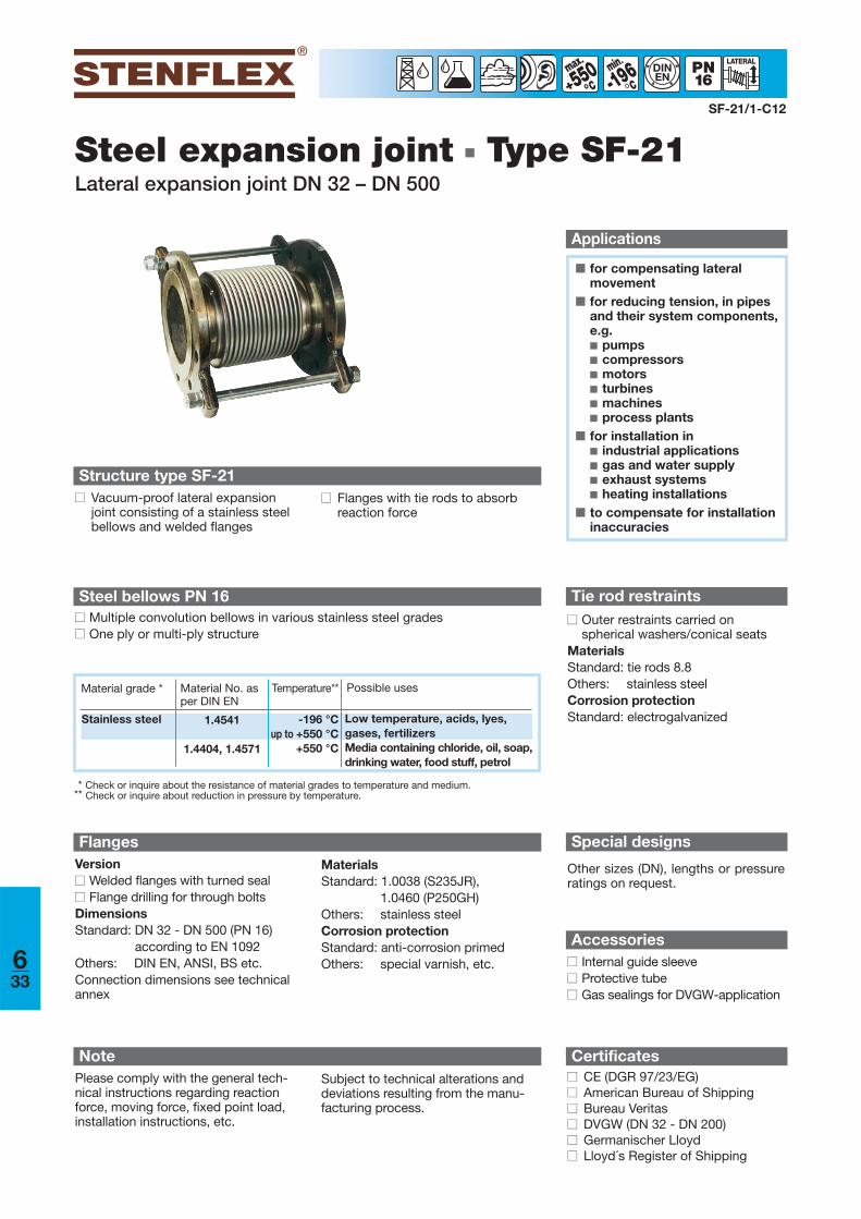
Steel expansion joint ■ Type SF-21Lateral expansion joint DN 32 – DN 500
SF-21/1-C12
-196min
°550°
DINEN
Structure type SF-21■■ Vacuum-proof lateral expansion
joint consisting of a stainless steelbellows and welded flanges
■■ Flanges with tie rods to absorb reaction force
FlangesVersion■■ Welded flanges with turned seal■■ Flange drilling for through boltsDimensionsStandard: DN 32 - DN 500 (PN 16)
according to EN 1092Others: DIN EN, ANSI, BS etc. Connection dimensions see technicalannex
MaterialsStandard: 1.0038 (S235JR),
1.0460 (P250GH)Others: stainless steelCorrosion protectionStandard: anti-corrosion primedOthers: special varnish, etc.
Steel bellows PN 16■■ Multiple convolution bellows in various stainless steel grades■■ One ply or multi-ply structure
■ for compensating lateralmovement
■ for reducing tension, in pipesand their system components,e.g. ■ pumps■ compressors■ motors■ turbines■ machines■ process plants
■ for installation in■ industrial applications■ gas and water supply■ exhaust systems■ heating installations
■ to compensate for installationinaccuracies
Applications
* Check or inquire about the resistance of material grades to temperature and medium.** Check or inquire about reduction in pressure by temperature.
Material grade * Material No. asper DIN EN
Possible usesTemperature**
Stainless steel 1.4541
1.4404, 1.4571
-196 °Cup to +550 °C
+550 °C
Low temperature, acids, lyes, gases, fertilizersMedia containing chloride, oil, soap,drinking water, food stuff, petrol
NotePlease comply with the general tech-nical instructions regarding reactionforce, moving force, fixed point load,installation instructions, etc.
Subject to technical alterations anddeviations resulting from the manu-facturing process.
Accessories■■ Internal guide sleeve■■ Protective tube■■ Gas sealings for DVGW-application
Certificates■■ CE (DGR 97/23/EG)■■ American Bureau of Shipping■■ Bureau Veritas■■ DVGW (DN 32 - DN 200)■■ Germanischer Lloyd■■ Lloyd´s Register of Shipping
Tie rod restraints■■ Outer restraints carried on
spherical washers/conical seats MaterialsStandard: tie rods 8.8 Others: stainless steelCorrosion protectionStandard: electrogalvanized
Special designs
Other sizes (DN), lengths or pressureratings on request.
633
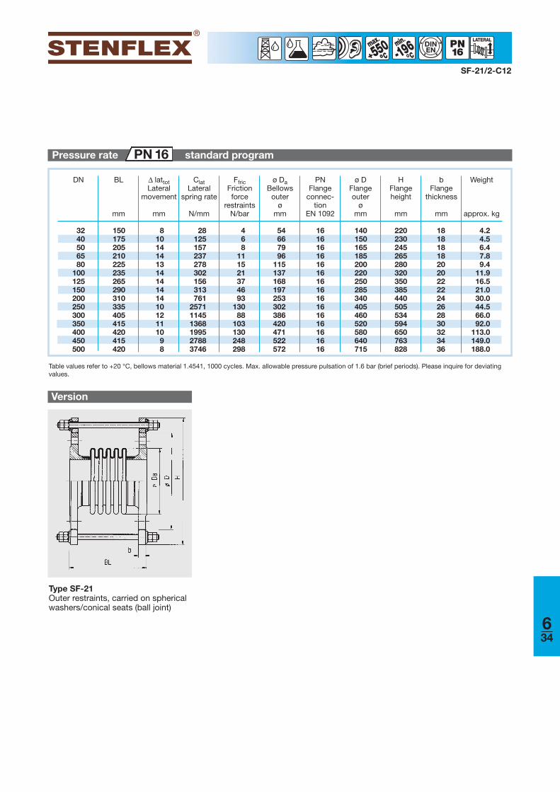
Version
-196min
°°550°°
DINEN
SF-21/2-C12
Type SF-21Outer restraints, carried on sphericalwashers/conical seats (ball joint)
DN BL
mm
Δ lattotLateral
movement
mm
ClatLateral
spring rate
N/mm
FfricFrictionforce
restraintsN/bar
ø DaBellows
outerø
mm
PNFlange
connec-tion
EN 1092
Weight
approx. kg
bFlange
thickness
mm
ø DFlangeouter
ømm
HFlangeheight
mm
Pressure rate standard programPN 16
Table values refer to +20 °C, bellows material 1.4541, 1000 cycles. Max. allowable pressure pulsation of 1.6 bar (brief periods). Please inquire for deviatingvalues.
634
3240506580
100125150200250300350400450500
150175205210225235265290310335405415420415420
810141413141414141012111098
28125157237278302156313761
257111451368199527883746
468
111521374693
13088
103130248298
54667996
115137168197253302386420471522572
161616161616161616161616161616
140150165185200220250285340405460520580640715
220230245265280320350385440505534594650763828
181818182020222224262830323436
4.24.56.47.89.4
11.916.521.030.044.566.092.0
113.0149.0188.0

Version
Steel expansion joint ■ Type SF-23Lateral expansion joint
■ for compensating simultaneous axial and lateralmovement
■ for reducing tension, in pipesand their system components,e.g.
■ pumps■ compressors■ motors■ turbines■ machines■ process plants
■ for installation in ■ long pipe routings■ industrial application■ exhaust systems■ heating installations
■ to compensate for installationinaccuracies
Applications
SF-23/C12
-196min
°550°
DINEN
Structure type SF-23■■ Vacuum-proof lateral expansion
joint consisting of two stainlesssteel bellows with connecting pipeand rotating flanges
Type SF-23
■■ Suitable for simultaneous movements
■■ Long connecting pipes allow largelateral movements
FlangesVersion■■ Rotating flanges■■ Flange drilling for through boltsDimensionsStandard: DN 50 - DN 1000 (PN 6)
according to EN 1092Others: DIN EN, ANSI, BS etc. Connection dimensions see technicalannex
MaterialsStandard: 1.0038 (S235JR)Others: stainless steel, etc. Corrosion protectionStandard: DN 50 - DN 250
electrogalvanized, DN 300 - DN 1000 anti-corrosion primed
Others: hot-dip galvanized, special varnish, specialcoating etc.
Steel bellows PN 1 / PN 6■■ Multiple convolution bellows in various stainless steel grades■■ One ply or multi-ply structure■■ DN 50 – DN 500 with flared ends■■ DN 600 – DN 1000 with pre-welded flared ends
Certificates■■ CE (DGR 97/23/EC)■■ American Bureau of Shipping■■ Bureau Veritas■■ Germanischer Lloyd■■ Lloyd´s Register of Shipping
Special designs
Other sizes (DN), lengths or pressureratings on request.
* Check or inquire about the resistance of material grades to temperature and medium.** Check or inquire about reduction in pressure by temperature.
Material grade * Material No. asper DIN EN
Possible usesTemperature**
Stainless steel 1.4541
1.4404, 1.4571
-196 °Cup to +550 °C
+550 °C
Low temperature, acids, lyes, gases, fertilizersMedia containing chloride, oil, soap,drinking water, food stuff, petrol
NotePlease comply with the general tech-nical instructions regarding reactionforce, moving force, fixed point load,installation instructions, etc.
Subject to technical alterations anddeviations resulting from the manu-facturing process.
Connecting pipe/guide sleeveMaterialsStandard: 1.0305 (St 35.8)
1.0038 (S235JR)Others: stainless steel etc.Corrosion protectionStandard: anti-corrosion primedOthers: special varnish etc.
635
Customized
production
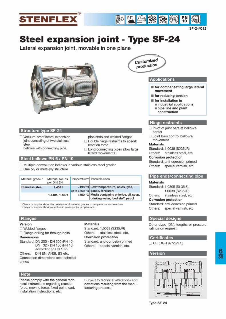
636
Version
Steel expansion joint ■ Type SF-24Lateral expansion joint, movable in one plane
■ for compensating large lateralmovement
■ for reducing tension■ for installation in
■ industrial applications■ pipe line and plant
construction
Applications
SF-24/C12
-196min
°°550°°
DINEN
Structure type SF-24■■ Vacuum-proof lateral expansion
joint consisting of two stainlesssteel bellows with connecting pipe,
Customized
production
pipe ends and welded flanges■■ Double hinge restraints to absorb
reaction force■■ Long connecting pipes allow large
lateral movements
FlangesVersion■■ Welded flanges■■ Flange drilling for through boltsDimensionsStandard: DN 200 - DN 500 (PN 10)
DN 32 - DN 150 (PN 16)according to EN 1092
Others: DIN EN, ANSI, BS etc. Connection dimensions see technicalannex
MaterialsStandard: 1.0038 (S235JR)Others: stainless steel, etc.Corrosion protectionStandard: anti-corrosion primedOthers: special varnish, etc.
Steel bellows PN 6 / PN 10■■ Multiple convolution bellows in various stainless steel grades■■ One ply or multi-ply structure
Certificates■■ CE (DGR 97/23/EC)
Hinge restraints■■ Pivot of joint bars at bellow’s
center■■ Joint bars control bellow’s
movementMaterialsStandard: 1.0038 (S235JR)Others: stainless steel, etc.Corrosion protectionStandard: anti-corrosion primedOthers: special varnish, etc.
Pipe ends/connecting pipeMaterialsStandard: 1.0305 (St 35.8),
1.0038 (S235JR)Others: stainless steel, etc.Corrosion protectionStandard: anti-corrosion primedOthers: special varnish, etc.
Special designsOther sizes (DN), lengths or pressureratings on request.
Type SF-24
* Check or inquire about the resistance of material grades to temperature and medium.** Check or inquire about reduction in pressure by temperature.
Material grade * Material No. asper DIN EN
Possible usesTemperature**
Stainless steel 1.4541
1.4404, 1.4571
-196 °Cup to +550 °C
+550 °C
Low temperature, acids, lyes, gases, fertilizersMedia containing chloride, oil, soap,drinking water, food stuff, petrol
NotePlease comply with the general tech-nical instructions regarding reactionforce, moving force, fixed point load,installation instructions, etc.
Subject to technical alterations anddeviations resulting from the manu-facturing process.

Customized
production
Version
Steel expansion joint ■ Type SF-25Lateral expansion joint, movable in all planes
■ for compensating large lateralmovement
■ for 3D movement absorptionin pipe systems
■ for reducing tension■ for installation in
■ industrial applications■ pipe line and plant
construction
Applications
SF-25/C12
550°°
DINEN
Structure type SF-25■■ Vacuum-proof lateral expansion
joint consisting of two stainlesssteel bellows with connecting pipe,pipe ends and welded flanges
■■ Tie rods to absorb reactiong force■■ Long connecting pipes allow large
movements
Certificates■■ CE (DGR 97/23/EC)
Tie rod restraints■■ Outer restraints, carried on
spherical washers and conicalseats
MaterialsStandard: tie rods 8.8Others: stainless steel, etc.Corrosion protectionStandard: electrogalvanized
Pipe ends/connecting pipeMaterialsStandard: 1.0305 (St 35.8),
1.0038 (S235JR)Others: stainless steel, etc.Corrosion protectionStandard: anti-corrosion primedOthers: special varnish, etc.
-196min
°°
Special designs
Other sizes (DN), lengths or pressureratings on request.
Type SF-25
FlangesVersion■■ Welded flanges■■ Flange drilling for through boltsDimensionsStandard: DN 200 - DN 500 (PN 10)
DN 32 - DN 150 (PN 16)according to EN 1092
Others: DIN EN, ANSI, BS etc. Connection dimensions see technicalannex
MaterialsStandard: 1.0038 (S235JR)Others: stainless steel, etc.Corrosion protectionStandard: anti-corrosion primedOthers: special varnish, etc.
Steel bellows PN 10■■ Multiple convolution bellows in various stainless steel grades■■ One ply or multi-ply structure
* Check or inquire about the resistance of material grades to temperature and medium.** Check or inquire about reduction in pressure by temperature.
Material grade * Material No. asper DIN EN
Possible usesTemperature**
Stainless steel 1.4541
1.4404, 1.4571
-196 °Cup to +550 °C
+550 °C
Low temperature, acids, lyes, gases, fertilizersMedia containing chloride, oil, soap,drinking water, food stuff, petrol
NotePlease comply with the general tech-nical instructions regarding reactionforce, moving force, fixed point load,installation instructions, etc.
Subject to technical alterations anddeviations resulting from the manu-facturing process.
637
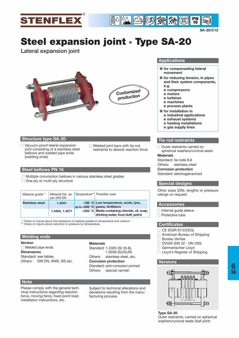
Customized
production
638
Steel expansion joint ■ Type SA-20Lateral expansion joint
SA-20/C12
-196min
°550°
DINEN
Structure type SA-20■■ Vacuum-proof lateral expansion
joint consisting of a stainless steel bellows and welded pipe ends(welding ends)
■■ Welded joint bars with tie rod restraints to absorb reaction force
Steel bellows PN 16
■■ Multiple convolution bellows in various stainless steel grades■■ One ply or multi-ply structure
Welding endsVersion■■ Welded pipe endsDimensionsStandard: see tablesOthers: DIN EN, ANSI, BS etc.
MaterialsStandard: 1.0305 (St 35.8),
1.0038 (S235JR)Others: stainless steel, etc.Corrosion protectionStandard: anti-corrosion primed Others: special varnish
Certificates■■ CE (DGR 97/23/EG)■■ American Bureau of Shipping■■ Bureau Veritas■■ DVGW (DN 32 - DN 200)■■ Germanischer Lloyd■■ Lloyd´s Register of Shipping
■ for compensating lateralmovement
■ for reducing tension, in pipesand their system components,e.g. ■ compressors■ motors■ turbines■ machines■ process plants
■ for installation in■ industrial applications■ exhaust systems■ heating installations■ gas supply lines
Applications
* Check or inquire about the resistance of material grades to temperature and medium.** Check or inquire about reduction in pressure by temperature.
Material grade * Material No. asper DIN EN
Possible usesTemperature**
Stainless steel 1.4541
1.4404, 1.4571
-196 °Cup to +550 °C
+550 °C
Low temperature, acids, lyes, gases, fertilizersMedia containing chloride, oil, soap,drinking water, food stuff, petrol
NotePlease comply with the general tech-nical instructions regarding reactionforce, moving force, fixed point load,installation instructions, etc.
Subject to technical alterations anddeviations resulting from the manu-facturing process.
Tie rod restraints■■ Outer restraints carried on
spherical washers/conical seats MaterialsStandard: tie rods 8.8 Others: stainless steelCorrosion protectionStandard: electrogalvanized
Accessories■■ Internal guide sleeve■■ Protective tube
Special designs
Other sizes (DN), lengths or pressureratings on request.
Versions
Type SA-20Outer restraints, carried on sphericalwashers/conical seats (ball joint)
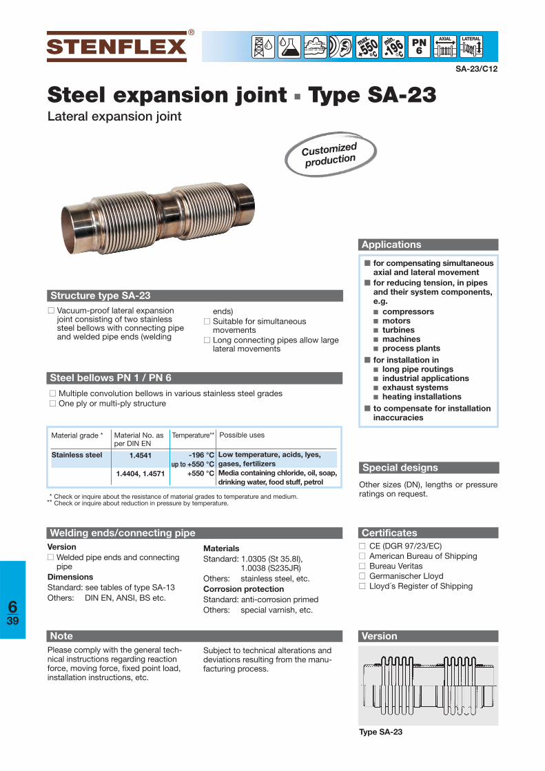
Version
Steel expansion joint ■ Type SA-23Lateral expansion joint
■ for compensating simultaneousaxial and lateral movement
■ for reducing tension, in pipesand their system components,e.g. ■ compressors■ motors■ turbines■ machines■ process plants
■ for installation in■ long pipe routings■ industrial applications■ exhaust systems■ heating installations
■ to compensate for installationinaccuracies
Applications
SA-23/C12
-196min
°550°
Structure type SA-23■■ Vacuum-proof lateral expansion
joint consisting of two stainlesssteel bellows with connecting pipeand welded pipe ends (welding
ends)■■ Suitable for simultaneous
movements■■ Long connecting pipes allow large
lateral movements
Steel bellows PN 1 / PN 6
■■ Multiple convolution bellows in various stainless steel grades■■ One ply or multi-ply structure
Type SA-23
Certificates■■ CE (DGR 97/23/EC)■■ American Bureau of Shipping■■ Bureau Veritas■■ Germanischer Lloyd■■ Lloyd´s Register of Shipping
Special designs
Other sizes (DN), lengths or pressureratings on request.
Customized
production
Welding ends/connecting pipeVersion■■ Welded pipe ends and connecting
pipeDimensionsStandard: see tables of type SA-13Others: DIN EN, ANSI, BS etc.
MaterialsStandard: 1.0305 (St 35.8I),
1.0038 (S235JR)Others: stainless steel, etc.Corrosion protectionStandard: anti-corrosion primed Others: special varnish, etc.
* Check or inquire about the resistance of material grades to temperature and medium.** Check or inquire about reduction in pressure by temperature.
Material grade * Material No. asper DIN EN
Possible usesTemperature**
Stainless steel 1.4541
1.4404, 1.4571
-196 °Cup to +550 °C
+550 °C
Low temperature, acids, lyes, gases, fertilizersMedia containing chloride, oil, soap,drinking water, food stuff, petrol
NotePlease comply with the general tech-nical instructions regarding reactionforce, moving force, fixed point load,installation instructions, etc.
Subject to technical alterations anddeviations resulting from the manu-facturing process.
639
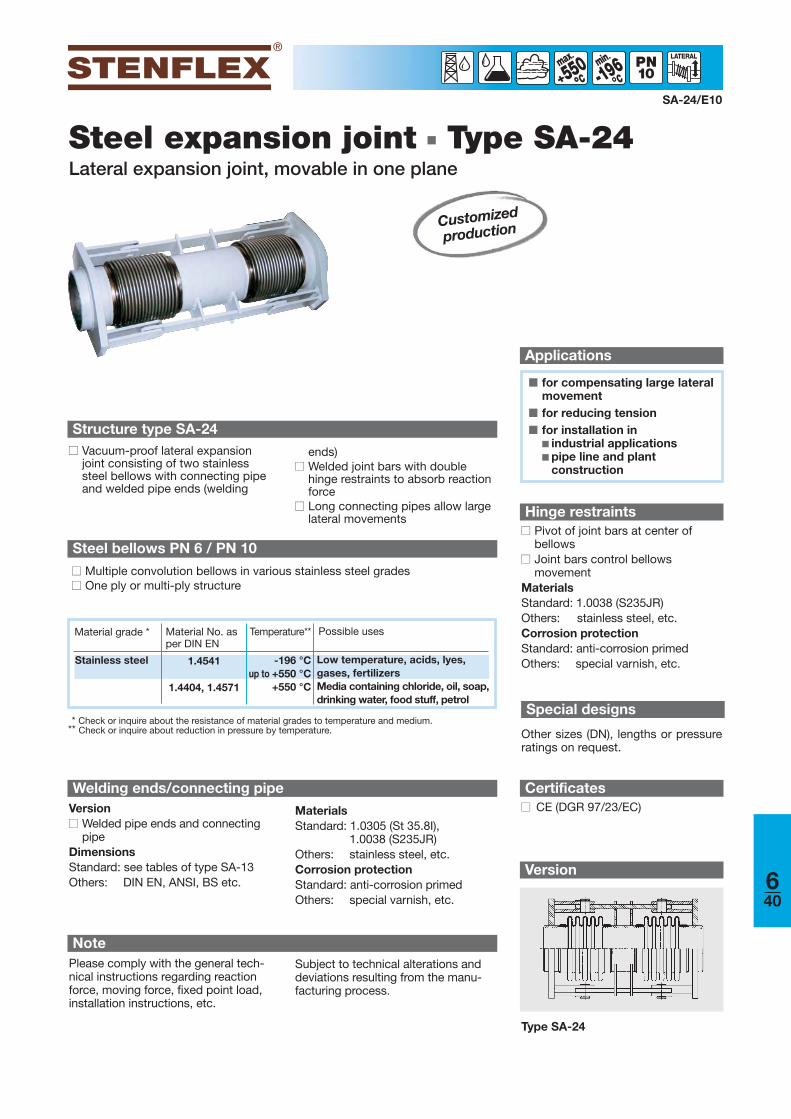
Version
Steel expansion joint ■ Type SA-24Lateral expansion joint, movable in one plane
■ for compensating large lateralmovement
■ for reducing tension■ for installation in
■ industrial applications■ pipe line and plant
construction
Applications
SA-24/E10
-196min
°°550°°
Type SA-24
Certificates■■ CE (DGR 97/23/EC)
Structure type SA-24■■ Vacuum-proof lateral expansion
joint consisting of two stainlesssteel bellows with connecting pipeand welded pipe ends (welding
ends)■■ Welded joint bars with double
hinge restraints to absorb reactionforce
■■ Long connecting pipes allow largelateral movements
Customized
production
Steel bellows PN 6 / PN 10
■■ Multiple convolution bellows in various stainless steel grades■■ One ply or multi-ply structure
Welding ends/connecting pipeVersion■■ Welded pipe ends and connecting
pipeDimensionsStandard: see tables of type SA-13Others: DIN EN, ANSI, BS etc.
MaterialsStandard: 1.0305 (St 35.8I),
1.0038 (S235JR)Others: stainless steel, etc.Corrosion protectionStandard: anti-corrosion primed Others: special varnish, etc.
* Check or inquire about the resistance of material grades to temperature and medium.** Check or inquire about reduction in pressure by temperature.
Material grade * Material No. asper DIN EN
Possible usesTemperature**
Stainless steel 1.4541
1.4404, 1.4571
-196 °Cup to +550 °C
+550 °C
Low temperature, acids, lyes, gases, fertilizersMedia containing chloride, oil, soap,drinking water, food stuff, petrol
NotePlease comply with the general tech-nical instructions regarding reactionforce, moving force, fixed point load,installation instructions, etc.
Subject to technical alterations anddeviations resulting from the manu-facturing process.
Hinge restraints■■ Pivot of joint bars at center of
bellows ■■ Joint bars control bellows
movementMaterialsStandard: 1.0038 (S235JR)Others: stainless steel, etc.Corrosion protectionStandard: anti-corrosion primedOthers: special varnish, etc.
Special designs
Other sizes (DN), lengths or pressureratings on request.
640
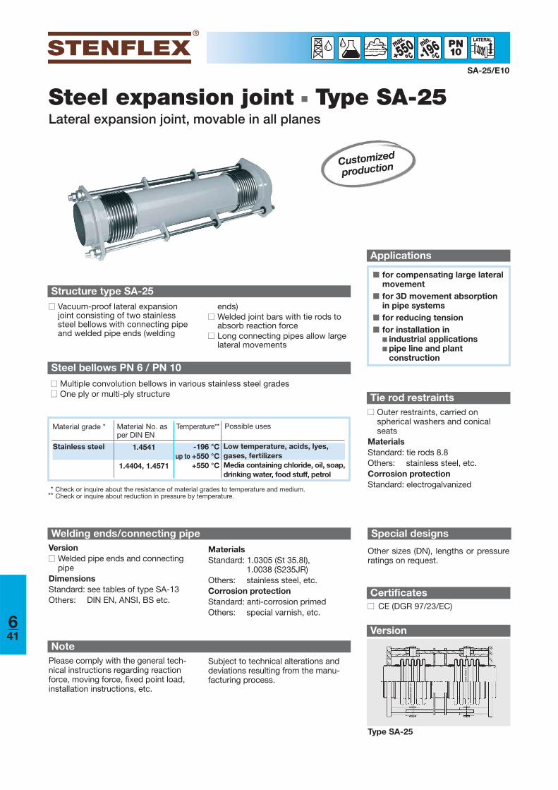
Version
Steel expansion joint ■ Type SA-25Lateral expansion joint, movable in all planes
SA-25/E10
-196min
°°550°°
■ for compensating large lateralmovement
■ for 3D movement absorptionin pipe systems
■ for reducing tension■ for installation in
■ industrial applications■ pipe line and plant
construction
Applications
Type SA-25
Structure type SA-25■■ Vacuum-proof lateral expansion
joint consisting of two stainlesssteel bellows with connecting pipeand welded pipe ends (welding
ends)■■ Welded joint bars with tie rods to
absorb reaction force■■ Long connecting pipes allow large
lateral movements
Certificates■■ CE (DGR 97/23/EC)
Tie rod restraints■■ Outer restraints, carried on
spherical washers and conicalseats
MaterialsStandard: tie rods 8.8 Others: stainless steel, etc.Corrosion protectionStandard: electrogalvanized
Customized
production
Steel bellows PN 6 / PN 10
■■ Multiple convolution bellows in various stainless steel grades■■ One ply or multi-ply structure
Welding ends/connecting pipeVersion■■ Welded pipe ends and connecting
pipeDimensionsStandard: see tables of type SA-13Others: DIN EN, ANSI, BS etc.
MaterialsStandard: 1.0305 (St 35.8I),
1.0038 (S235JR)Others: stainless steel, etc.Corrosion protectionStandard: anti-corrosion primed Others: special varnish, etc.
* Check or inquire about the resistance of material grades to temperature and medium.** Check or inquire about reduction in pressure by temperature.
Material grade * Material No. asper DIN EN
Possible usesTemperature**
Stainless steel 1.4541
1.4404, 1.4571
-196 °Cup to +550 °C
+550 °C
Low temperature, acids, lyes, gases, fertilizersMedia containing chloride, oil, soap,drinking water, food stuff, petrol
NotePlease comply with the general tech-nical instructions regarding reactionforce, moving force, fixed point load,installation instructions, etc.
Subject to technical alterations anddeviations resulting from the manu-facturing process.
Special designs
Other sizes (DN), lengths or pressureratings on request.
641
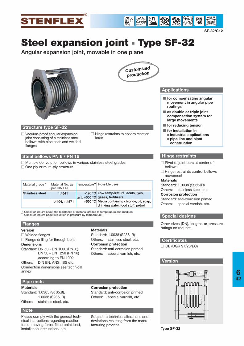
Steel expansion joint ■ Type SF-32Angular expansion joint, movable in one plane
Applications
SF-32/C12
-196min
°°550°°
DINEN
Structure type SF-32■■ Vacuum-proof angular expansion
joint consisting of a stainless steel bellows with pipe ends and weldedflanges
■ for compensating angularmovement in angular piperoutings
■ as double or triple joint compensation system forlarge movements
■ for reducing tension■ for installation in
■ industrial applications■ pipe line and plant
construction
■■ Hinge restraints to absorb reactionforce
FlangesVersion■■ Welded flanges■■ Flange drilling for through boltsDimensionsStandard: DN 50 - DN 1000 (PN 6)
DN 50 - DN 250 (PN 16)according to EN 1092
Others: DIN EN, ANSI, BS etc. Connection dimensions see technicalannex
MaterialsStandard: 1.0038 (S235JR)Others: stainless steel, etc.Corrosion protectionStandard: anti-corrosion primed Others: special varnish, etc.
Steel bellows PN 6 / PN 16■■ Multiple convolution bellows in various stainless steel grades■■ One ply or multi-ply structure
Certificates■■ CE (DGR 97/23/EC)
Hinge restraints■■ Pivot of joint bars at center of
bellows ■■ Hinge restraints control bellows
movementMaterialsStandard: 1.0038 (S235JR)Others: stainless steel, etc.Corrosion protectionStandard: anti-corrosion primed Others: special varnish, etc.
Pipe ends
Version
Type SF-32
Customized
production
* Check or inquire about the resistance of material grades to temperature and medium.** Check or inquire about reduction in pressure by temperature.
Material grade * Material No. asper DIN EN
Possible usesTemperature**
Stainless steel 1.4541
1.4404, 1.4571
-196 °Cup to +550 °C
+550 °C
Low temperature, acids, lyes, gases, fertilizersMedia containing chloride, oil, soap,drinking water, food stuff, petrol
Special designs
Other sizes (DN), lengths or pressureratings on request.
NotePlease comply with the general tech-nical instructions regarding reactionforce, moving force, fixed point load,installation instructions, etc.
Subject to technical alterations anddeviations resulting from the manu-facturing process.
MaterialsStandard: 1.0305 (St 35.8),
1.0038 (S235JR)Others: stainless steel, etc.
Corrosion protectionStandard: anti-corrosion primed Others: special varnish, etc.
642

Steel expansion joint ■ Type SF-33Angular expansion joint, cardanic movable
■ for compensating angularmovement in angular and deflecting pipe routings
■ as double or triple joint compensation system forlarge movements
■ for reducing tension■ for installation in
■ industrial applications■ pipe line and plant
construction
Applications
SF-33/E10
-196min
°°550°°
DINEN
Version
Structure type SF-33■■ Vacuum-proof angular expansion
joint consisting of a stainless steel bellows with pipe ends and weldedflanges
Type SF-33
■■ Welded cardan hinge restraints toabsorb reaction force Cardan hinge restraints
■■ Pivot of joint bars at center of bellows
■■ Hinge restraints control bellowsmovement
MaterialsStandard: 1.0038 (S235JR)Others: stainless steel, etc.Corrosion protectionStandard: anti-corrosion primed Others: special varnish, etc.
Pipe endsMaterialsStandard: 1.0305 (St 35.8),
1.0038 (S235JR)Others: stainless steel, etc.
Corrosion protectionStandard: anti-corrosion primed Others: special varnish, etc.
Customized
production
FlangesVersion■■ Welded flanges■■ Flange drilling for through boltsDimensionsStandard: DN 50 - DN 500 (PN 6)
DN 50 - DN 250 (PN 16)according to EN 1092
Others: DIN EN, ANSI, BS etc. Connection dimensions see technicalannex
MaterialsStandard: 1.0038 (S235JR)Others: stainless steel, etc.Corrosion protectionStandard: anti-corrosion primed Others: special varnish, etc.
Steel bellows PN 6 / PN 16■■ Multiple convolution bellows in various stainless steel grades■■ One ply or multi-ply structure
Certificates■■ CE (DGR 97/23/EC)
* Check or inquire about the resistance of material grades to temperature and medium.** Check or inquire about reduction in pressure by temperature.
Material grade * Material No. asper DIN EN
Possible usesTemperature**
Stainless steel 1.4541
1.4404, 1.4571
-196 °Cup to +550 °C
+550 °C
Low temperature, acids, lyes, gases, fertilizersMedia containing chloride, oil, soap,drinking water, food stuff, petrol
Special designs
Other sizes (DN), lengths or pressureratings on request.
NotePlease comply with the general tech-nical instructions regarding reactionforce, moving force, fixed point load,installation instructions, etc.
Subject to technical alterations anddeviations resulting from the manu-facturing process.
643
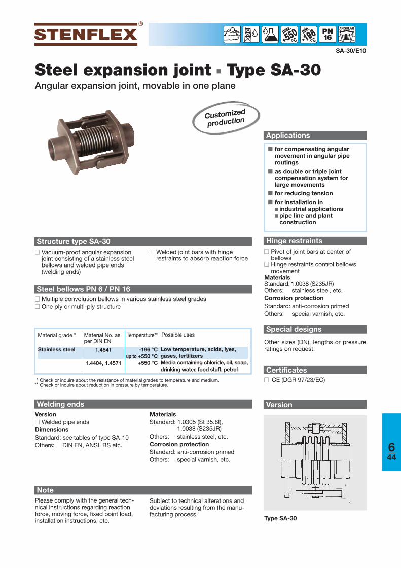
Steel expansion joint ■ Type SA-30Angular expansion joint, movable in one plane
■ for compensating angularmovement in angular piperoutings
■ as double or triple joint compensation system forlarge movements
■ for reducing tension■ for installation in
■ industrial applications■ pipe line and plant
construction
Applications
SA-30/E10
Version
Hinge restraints■■ Pivot of joint bars at center of
bellows ■■ Hinge restraints control bellows
movementMaterialsStandard: 1.0038 (S235JR)Others: stainless steel, etc.Corrosion protectionStandard: anti-corrosion primed Others: special varnish, etc.
-196min
°°550°°
Type SA-30
Structure type SA-30■■ Vacuum-proof angular expansion
joint consisting of a stainless steelbellows and welded pipe ends(welding ends)
■■ Welded joint bars with hinge restraints to absorb reaction force
Certificates■■ CE (DGR 97/23/EC)
Customized
production
Steel bellows PN 6 / PN 16■■ Multiple convolution bellows in various stainless steel grades■■ One ply or multi-ply structure
* Check or inquire about the resistance of material grades to temperature and medium.** Check or inquire about reduction in pressure by temperature.
Material grade * Material No. asper DIN EN
Possible usesTemperature**
Stainless steel 1.4541
1.4404, 1.4571
-196 °Cup to +550 °C
+550 °C
Low temperature, acids, lyes, gases, fertilizersMedia containing chloride, oil, soap,drinking water, food stuff, petrol
Welding endsVersion■■ Welded pipe ends DimensionsStandard: see tables of type SA-10Others: DIN EN, ANSI, BS etc.
MaterialsStandard: 1.0305 (St 35.8I),
1.0038 (S235JR)Others: stainless steel, etc.Corrosion protectionStandard: anti-corrosion primed Others: special varnish, etc.
NotePlease comply with the general tech-nical instructions regarding reactionforce, moving force, fixed point load,installation instructions, etc.
Subject to technical alterations anddeviations resulting from the manu-facturing process.
Special designs
Other sizes (DN), lengths or pressureratings on request.
644
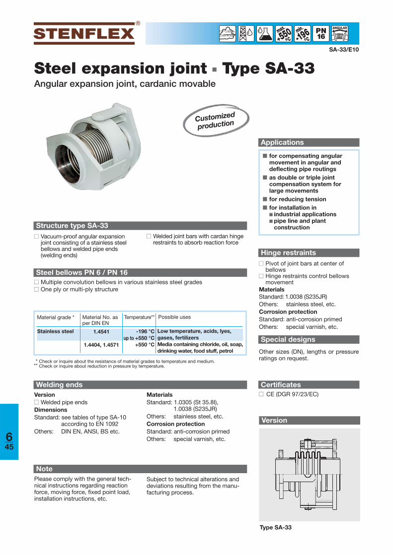
Steel expansion joint ■ Type SA-33Angular expansion joint, cardanic movable
■ for compensating angularmovement in angular and deflecting pipe routings
■ as double or triple joint compensation system forlarge movements
■ for reducing tension■ for installation in
■ industrial applications■ pipe line and plant
construction
Applications
SA-33/E10
-196min
°°550°°
Version
Type SA-33
Structure type SA-33■■ Vacuum-proof angular expansion
joint consisting of a stainless steel bellows and welded pipe ends(welding ends)
■■ Welded joint bars with cardan hingerestraints to absorb reaction force
Customized
production
Steel bellows PN 6 / PN 16■■ Multiple convolution bellows in various stainless steel grades■■ One ply or multi-ply structure
* Check or inquire about the resistance of material grades to temperature and medium.** Check or inquire about reduction in pressure by temperature.
Material grade * Material No. asper DIN EN
Possible usesTemperature**
Stainless steel 1.4541
1.4404, 1.4571
-196 °Cup to +550 °C
+550 °C
Low temperature, acids, lyes, gases, fertilizersMedia containing chloride, oil, soap,drinking water, food stuff, petrol
Welding endsVersion■■ Welded pipe ends DimensionsStandard: see tables of type SA-10
according to EN 1092Others: DIN EN, ANSI, BS etc.
MaterialsStandard: 1.0305 (St 35.8I),
1.0038 (S235JR)Others: stainless steel, etc.Corrosion protectionStandard: anti-corrosion primed Others: special varnish, etc.
NotePlease comply with the general tech-nical instructions regarding reactionforce, moving force, fixed point load,installation instructions, etc.
Subject to technical alterations anddeviations resulting from the manu-facturing process.
Hinge restraints■■ Pivot of joint bars at center of
bellows ■■ Hinge restraints control bellows
movementMaterialsStandard: 1.0038 (S235JR)Others: stainless steel, etc.Corrosion protectionStandard: anti-corrosion primed Others: special varnish, etc.
Certificates■■ CE (DGR 97/23/EC)
Special designs
Other sizes (DN), lengths or pressureratings on request.
645
Related Documents