ARCH 631 Note Set 21.1 F2012abn 1 Steel Design Notation: a = name for width dimension A = name for area A g = gross area, equal to the total area ignoring any holes A req’d-adj = area required at allowable stress when shear is adjusted to include self weight A w = area of the web of a wide flange section, as is A web AISC= American Institute of Steel Construction ASD = allowable stress design b = name for a (base) width = name for height dimension b f = width of the flange of a steel beam cross section B = width of a column base plate B 1 = factor for determining M u for combined bending and compression c = largest distance from the neutral axis to the top or bottom edge of a beam. as is c max c 1 = coefficient for shear stress for a rectangular bar in torsion C b = modification factor for moment in ASD & LRFD steel beam design C m = modification factor accounting for combined stress in steel design C v = web shear coefficient d = name for depth = depth of a wide flange section D = shorthand for dead load DL = shorthand for dead load E = shorthand for earthquake load = modulus of elasticity f a = axial stress f b = bending stress f p = bearing stress f v = shear stress f v-max = maximum shear stress f y = yield stress F = shorthand for fluid load F a = allowable axial (compressive) stress F b = allowable bending stress F cr = flexural buckling stress F e = elastic critical buckling stress F p = allowable bearing stress F u = ultimate stress prior to failure F y = yield strength F yw = yield strength of web material h = name for a height h c = height of the web of a wide flange steel section H = shorthand for lateral pressure load I = moment of inertia with respect to neutral axis bending I y = moment of inertia about the y axis J = polar moment of inertia k = distance from outer face of W flange to the web toe of fillet = shape factor for plastic design of steel beams K = effective length factor for columns, as is k l = name for length, as is L = column base plate design variable L = name for length or span length, as is l = shorthand for live load L b = unbraced length of a steel beam in LRFD design L e = effective length that can buckle for column design, as is e L r = shorthand for live roof load = maximum unbraced length of a steel beam in LRFD design for inelastic lateral-torsional buckling L p = maximum unbraced length of a steel beam in LRFD design for full plastic flexural strength LL = shorthand for live load LRFD = load and resistance factor design m = edge distance for a column base plate M = internal bending moment M a = required bending moment (ASD) M max = maximum internal bending moment M max-adj = maximum bending moment adjusted to include self weight

Welcome message from author
This document is posted to help you gain knowledge. Please leave a comment to let me know what you think about it! Share it to your friends and learn new things together.
Transcript

ARCH 631 Note Set 21.1 F2012abn
1
Steel Design
Notation:
a = name for width dimension
A = name for area
Ag = gross area, equal to the total area
ignoring any holes
Areq’d-adj = area required at allowable stress
when shear is adjusted to include
self weight
Aw = area of the web of a wide flange
section, as is Aweb
AISC= American Institute of Steel
Construction
ASD = allowable stress design
b = name for a (base) width
= name for height dimension
bf = width of the flange of a steel beam
cross section
B = width of a column base plate
B1 = factor for determining Mu for
combined bending and compression
c = largest distance from the neutral
axis to the top or bottom edge of a
beam. as is cmax
c1 = coefficient for shear stress for a
rectangular bar in torsion
Cb = modification factor for moment in
ASD & LRFD steel beam design
Cm = modification factor accounting for
combined stress in steel design
Cv = web shear coefficient
d = name for depth
= depth of a wide flange section
D = shorthand for dead load
DL = shorthand for dead load
E = shorthand for earthquake load
= modulus of elasticity
fa = axial stress
fb = bending stress
fp = bearing stress
fv = shear stress
fv-max = maximum shear stress
fy = yield stress
F = shorthand for fluid load
Fa = allowable axial (compressive) stress
Fb = allowable bending stress
Fcr = flexural buckling stress
Fe = elastic critical buckling stress
Fp = allowable bearing stress
Fu = ultimate stress prior to failure
Fy = yield strength
Fyw = yield strength of web material
h = name for a height
hc = height of the web of a wide flange
steel section
H = shorthand for lateral pressure load
I = moment of inertia with respect to
neutral axis bending
Iy = moment of inertia about the y axis
J = polar moment of inertia
k = distance from outer face of W
flange to the web toe of fillet
= shape factor for plastic design of
steel beams
K = effective length factor for columns,
as is k
l = name for length, as is L
= column base plate design variable
L = name for length or span length, as is
l
= shorthand for live load
Lb = unbraced length of a steel beam in
LRFD design
Le = effective length that can buckle for
column design, as is e
Lr = shorthand for live roof load
= maximum unbraced length of a
steel beam in LRFD design for
inelastic lateral-torsional buckling
Lp = maximum unbraced length of a
steel beam in LRFD design for full
plastic flexural strength
LL = shorthand for live load
LRFD = load and resistance factor design
m = edge distance for a column base
plate
M = internal bending moment
Ma = required bending moment (ASD)
Mmax = maximum internal bending moment
Mmax-adj = maximum bending moment
adjusted to include self weight
ARCH 631 Note Set 21.1 F2012abn
2
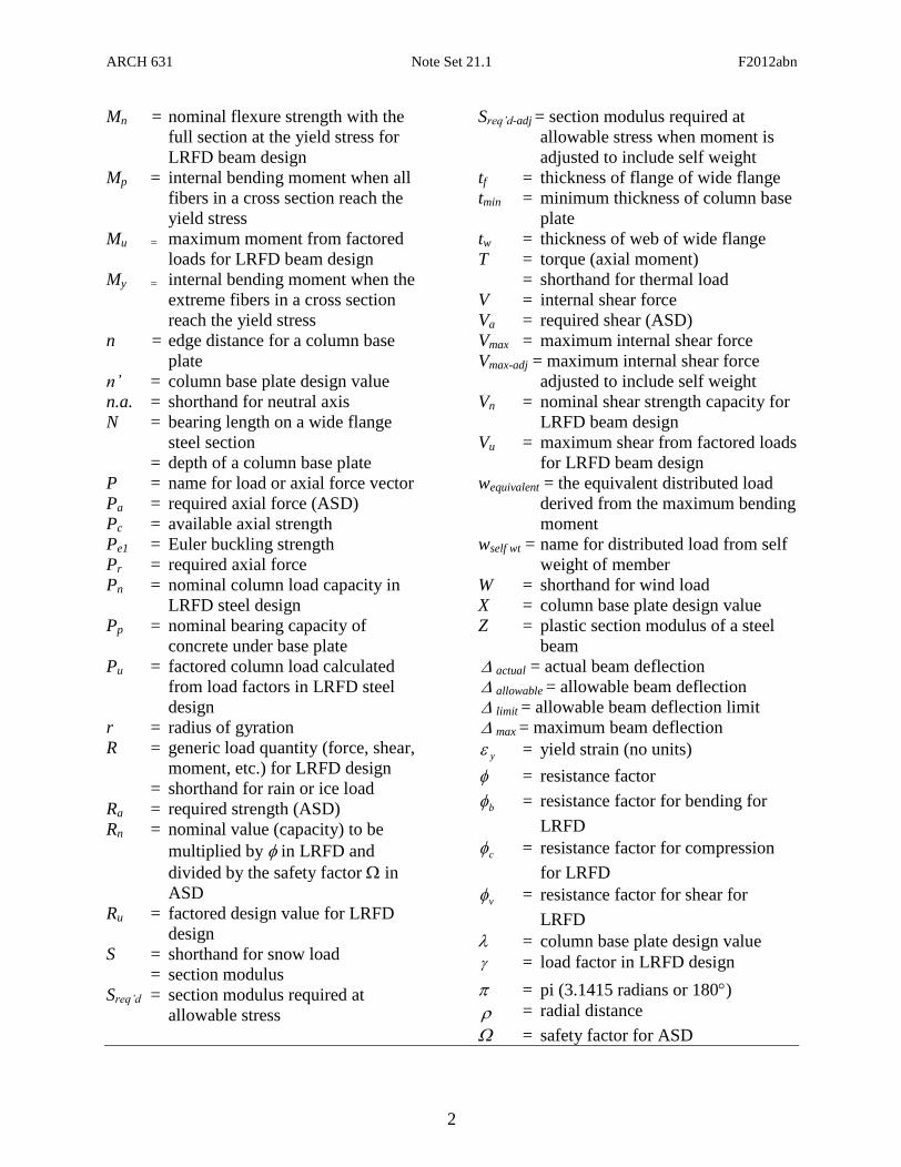
Mn = nominal flexure strength with the
full section at the yield stress for
LRFD beam design
Mp = internal bending moment when all
fibers in a cross section reach the
yield stress
Mu = maximum moment from factored
loads for LRFD beam design
My = internal bending moment when the
extreme fibers in a cross section
reach the yield stress
n = edge distance for a column base
plate
n’ = column base plate design value
n.a. = shorthand for neutral axis
N = bearing length on a wide flange
steel section
= depth of a column base plate
P = name for load or axial force vector
Pa = required axial force (ASD)
Pc = available axial strength
Pe1 = Euler buckling strength
Pr = required axial force
Pn = nominal column load capacity in
LRFD steel design
Pp = nominal bearing capacity of
concrete under base plate
Pu = factored column load calculated
from load factors in LRFD steel
design
r = radius of gyration
R = generic load quantity (force, shear,
moment, etc.) for LRFD design
= shorthand for rain or ice load
Ra = required strength (ASD)
Rn = nominal value (capacity) to be
multiplied by in LRFD and
divided by the safety factor in
ASD
Ru = factored design value for LRFD
design
S = shorthand for snow load
= section modulus
Sreq’d = section modulus required at
allowable stress
Sreq’d-adj = section modulus required at
allowable stress when moment is
adjusted to include self weight
tf = thickness of flange of wide flange
tmin = minimum thickness of column base
plate
tw = thickness of web of wide flange
T = torque (axial moment)
= shorthand for thermal load
V = internal shear force
Va = required shear (ASD)
Vmax = maximum internal shear force
Vmax-adj = maximum internal shear force
adjusted to include self weight
Vn = nominal shear strength capacity for
LRFD beam design
Vu = maximum shear from factored loads
for LRFD beam design
wequivalent = the equivalent distributed load
derived from the maximum bending
moment
wself wt = name for distributed load from self
weight of member
W = shorthand for wind load
X = column base plate design value
Z = plastic section modulus of a steel
beam
actual = actual beam deflection
allowable = allowable beam deflection
limit = allowable beam deflection limit
max = maximum beam deflection
y = yield strain (no units)
= resistance factor
b = resistance factor for bending for
LRFD
c = resistance factor for compression
for LRFD
v = resistance factor for shear for
LRFD
= column base plate design value
= load factor in LRFD design
= pi (3.1415 radians or 180)
= radial distance
= safety factor for ASD
ARCH 631 Note Set 21.1 F2012abn
3
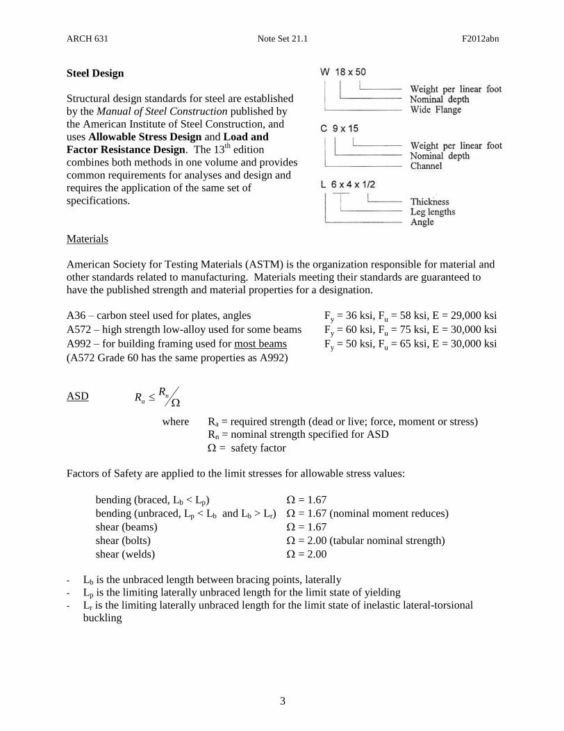
Steel Design
Structural design standards for steel are established
by the Manual of Steel Construction published by
the American Institute of Steel Construction, and
uses Allowable Stress Design and Load and
Factor Resistance Design. The 13th
edition
combines both methods in one volume and provides
common requirements for analyses and design and
requires the application of the same set of
specifications.
Materials
American Society for Testing Materials (ASTM) is the organization responsible for material and
other standards related to manufacturing. Materials meeting their standards are guaranteed to
have the published strength and material properties for a designation.
A36 – carbon steel used for plates, angles Fy = 36 ksi, Fu = 58 ksi, E = 29,000 ksi
A572 – high strength low-alloy used for some beams Fy = 60 ksi, Fu = 75 ksi, E = 30,000 ksi
A992 – for building framing used for most beams Fy = 50 ksi, Fu = 65 ksi, E = 30,000 ksi
(A572 Grade 60 has the same properties as A992)
ASD
where Ra = required strength (dead or live; force, moment or stress)
Rn = nominal strength specified for ASD
= safety factor
Factors of Safety are applied to the limit stresses for allowable stress values:
bending (braced, Lb < Lp) = 1.67
bending (unbraced, Lp < Lb and Lb > Lr) = 1.67 (nominal moment reduces)
shear (beams) = 1.67
shear (bolts) = 2.00 (tabular nominal strength)
shear (welds) = 2.00
Lb is the unbraced length between bracing points, laterally
Lp is the limiting laterally unbraced length for the limit state of yielding
Lr is the limiting laterally unbraced length for the limit state of inelastic lateral-torsional
buckling
n
a
RR

ARCH 631 Note Set 21.1 F2012abn
4
LRFD
where = resistance factor
= load factor for the type of load
R = load (dead or live; force, moment or stress)
Ru = factored load (moment or stress)
Rn = nominal load (ultimate capacity; force, moment or stress)
Nominal strength is defined as the
capacity of a structure or component to resist the effects of loads, as determined by
computations using specified material strengths (such as yield strength, Fy, or ultimate
strength, Fu) and dimensions and formulas derived from accepted principles of structural
mechanics or by field tests or laboratory tests of scaled models, allowing for modeling
effects and differences between laboratory and field conditions
Factored Load Combinations
The design strength, nR , of each structural element or structural assembly must equal or exceed
the design strength based on the ASCE-7 combinations of factored nominal loads:
1.4(D + F)
1.2(D + F) + 1.6(L + H) + 0.5(Lr or S or R)
1.2D + 1.6(Lr or S or R) + (L or 0.8W)
1.2D + 1.6W + L + 0.5(Lr or S or R)
1.2D + 1.0E + L + 0.2S
0.9D + 1.6W + 1.6 H
0.9D + 1.0E + 1.6 H
Criteria for Design of Beams
Allowable normal stress or normal stress from LRFD should not be
exceeded:
Knowing M and Fb, the minimum section modulus fitting the limit is:
Besides strength, we also need to be concerned about serviceability. This involves things like
limiting deflections & cracking, controlling noise and vibrations, preventing excessive
settlements of foundations and durability. When we know about a beam section and its material,
we can determine beam deformations.
y
ad'req
F
MZ
nu RR iiu RRwhere
)MMor/MM( nbuna I
McfForF bnb
b
d'reqF
MS

ARCH 631 Note Set 21.1 F2012abn
5
Determining Maximum Bending Moment
Drawing V and M diagrams will show us the maximum values for design. Computer
applications are very helpful.
Determining Maximum Bending Stress
For a prismatic member (constant cross section), the maximum normal stress will occur at the
maximum moment.
For a non-prismatic member, the stress varies with the cross section AND the moment.
Deflections
Elastic curve equations can be found in handbooks, textbooks, design manuals, etc...Computer
programs can be used as well.
Elastic curve equations can be superpositioned ONLY if the stresses are in the elastic range.
The deflected shape is roughly the same shape flipped as the bending moment diagram but is
constrained by supports and geometry.
Allowable Deflection Limits
All building codes and design codes limit deflection for beam types and damage that could
happen based on service condition and severity.
Use LL only DL+LL
Roof beams:
Industrial L/180 L/120
Commercial
plaster ceiling L/240 L/180
no plaster L/360 L/240
Floor beams:
Ordinary Usage L/360 L/240
Roof or floor (damageable elements) L/480
Lateral Buckling
With compression stresses in the top of a beam, a sudden “popping” or buckling can happen
even at low stresses. In order to prevent it, we need to brace it along the top, or laterally brace it,
or provide a bigger Iy.
valueL
allowableactual
ARCH 631 Note Set 21.1 F2012abn
6
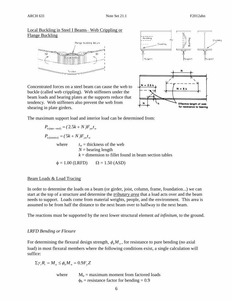
Local Buckling in Steel I Beams– Web Crippling or
Flange Buckling
Concentrated forces on a steel beam can cause the web to
buckle (called web crippling). Web stiffeners under the
beam loads and bearing plates at the supports reduce that
tendency. Web stiffeners also prevent the web from
shearing in plate girders.
The maximum support load and interior load can be determined from:
where tw = thickness of the web
N = bearing length
k = dimension to fillet found in beam section tables
= 1.00 (LRFD) = 1.50 (ASD)
Beam Loads & Load Tracing
In order to determine the loads on a beam (or girder, joist, column, frame, foundation...) we can
start at the top of a structure and determine the tributary area that a load acts over and the beam
needs to support. Loads come from material weights, people, and the environment. This area is
assumed to be from half the distance to the next beam over to halfway to the next beam.
The reactions must be supported by the next lower structural element ad infinitum, to the ground.
LRFD Bending or Flexure
For determining the flexural design strength, nb M , for resistance to pure bending (no axial
load) in most flexural members where the following conditions exist, a single calculation will
suffice:
where Mu = maximum moment from factored loads
b = resistance factor for bending = 0.9
ZFMMR ynbuii 9.0
wywn tF)Nk.(P 52end)(max
wywn tF)Nk(P 5(interior)
ARCH 631 Note Set 21.1 F2012abn
7
E
1
fy = 50ksi
y = 0.001724
f
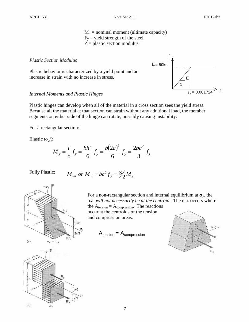
Mn = nominal moment (ultimate capacity)
Fy = yield strength of the steel
Z = plastic section modulus
Plastic Section Modulus
Plastic behavior is characterized by a yield point and an
increase in strain with no increase in stress.
Internal Moments and Plastic Hinges
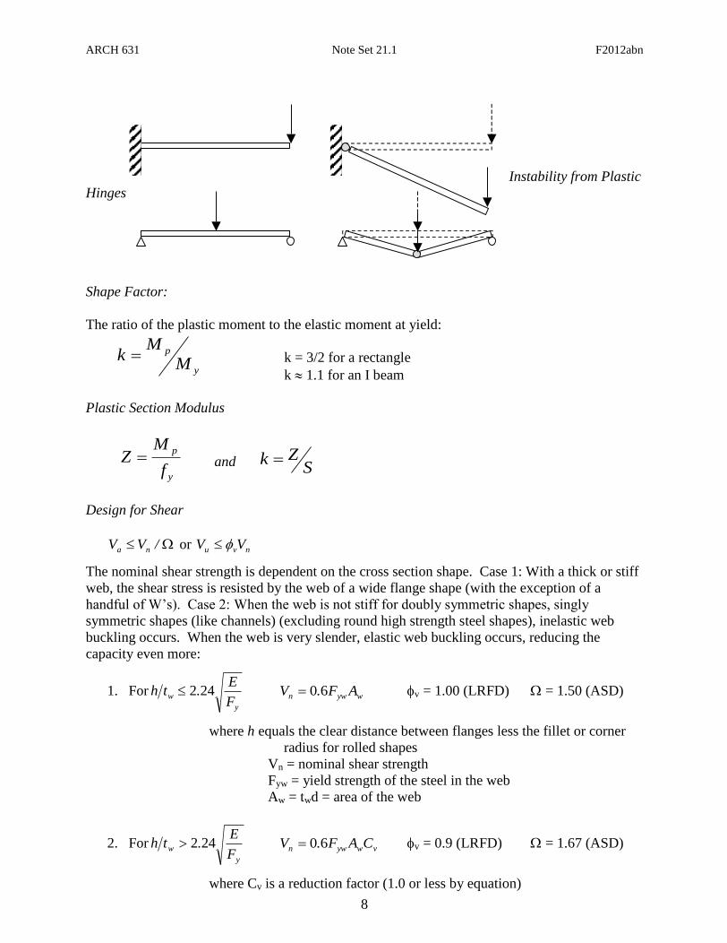
Plastic hinges can develop when all of the material in a cross section sees the yield stress.
Because all the material at that section can strain without any additional load, the member
segments on either side of the hinge can rotate, possibly causing instability.
For a rectangular section:
Elastic to fy:
Fully Plastic:
For a non-rectangular section and internal equilibrium at y, the
n.a. will not necessarily be at the centroid. The n.a. occurs where
the Atension = Acompression. The reactions
occur at the centroids of the tension
and compression areas.
yyyyy f
bcf
cbf
bhf
c
IM
3
2
6
2
6
222
yypult MfbcMorM2
32
Atension = Acompression
ARCH 631 Note Set 21.1 F2012abn
8
Instability from Plastic
Hinges
Shape Factor:
The ratio of the plastic moment to the elastic moment at yield:
k = 3/2 for a rectangle
k 1.1 for an I beam
Plastic Section Modulus
y
p
f
MZ and S
Zk
Design for Shear
/VV na or nvu VV
The nominal shear strength is dependent on the cross section shape. Case 1: With a thick or stiff
web, the shear stress is resisted by the web of a wide flange shape (with the exception of a
handful of W’s). Case 2: When the web is not stiff for doubly symmetric shapes, singly
symmetric shapes (like channels) (excluding round high strength steel shapes), inelastic web
buckling occurs. When the web is very slender, elastic web buckling occurs, reducing the
capacity even more:
1. Fory
wF
E.th 242 wywn AF.V 60 v = 1.00 (LRFD) = 1.50 (ASD)
where h equals the clear distance between flanges less the fillet or corner
radius for rolled shapes
Vn = nominal shear strength
Fyw = yield strength of the steel in the web
Aw = twd = area of the web
2. Fory
wF
E.th 242 vwywn CAF.V 60 v = 0.9 (LRFD) = 1.67 (ASD)
where Cv is a reduction factor (1.0 or less by equation)
y
p
M
Mk

ARCH 631 Note Set 21.1 F2012abn
9
Design for Flexure
/MM na or nbu MM
b = 0.90 (LRFD) = 1.67 (ASD)
The nominal flexural strength Mn is the lowest value obtained according to the limit states of
1. yielding, limited at lengthy
ypF
Er.L 761 , where ry is the radius of gyration in y
2. lateral-torsional buckling limited at length rL
3. flange local buckling
4. web local buckling
Beam design charts show available moment, Mn/ and nb M , for unbraced length, Lb, of the
compression flange in one-foot increments from 1 to 50 ft. for values of the bending coefficient
Cb = 1. For values of 1<Cb2.3, the required flexural strength Mu can be reduced by dividing it
by Cb. (Cb = 1 when the bending moment at any point within an unbraced length is larger than
that at both ends of the length. Cb of 1 is conservative and permitted to be used in any case.
When the free end is unbraced in a cantilever or overhang, Cb = 1. The full formula is provided
below.)
NOTE: the self weight is not included in determination of nb M
Compact Sections
For a laterally braced compact section (one for which the plastic moment can be reached before
local buckling) only the limit state of yielding is applicable. For unbraced compact beams and
non-compact tees and double angles, only the limit states of yielding and lateral-torsional
buckling are applicable.
Compact sections meet the following criteria: yf
f
F
E.
t
b380
2 and
yw
c
F
E.
t
h763
where:
bf = flange width in inches
tf = flange thickness in inches
E = modulus of elasticity in ksi
Fy = minimum yield stress in ksi
hc = height of the web in inches
tw = web thickness in inches
With lateral-torsional buckling the nominal flexural strength is
p
pr
pb
xyppbn MLL
LL)SF.M(MCM
70
ARCH 631 Note Set 21.1 F2012abn
10
where Cb is a modification factor for non-uniform moment diagrams where, when both ends
of the beam segment are braced:
Mmax = absolute value of the maximum moment in the unbraced beam segment
MA = absolute value of the moment at the quarter point of the unbraced beam segment
MB = absolute value of the moment at the center point of the unbraced beam segment
MC = absolute value of the moment at the three quarter point of the unbraced beam
segment length.
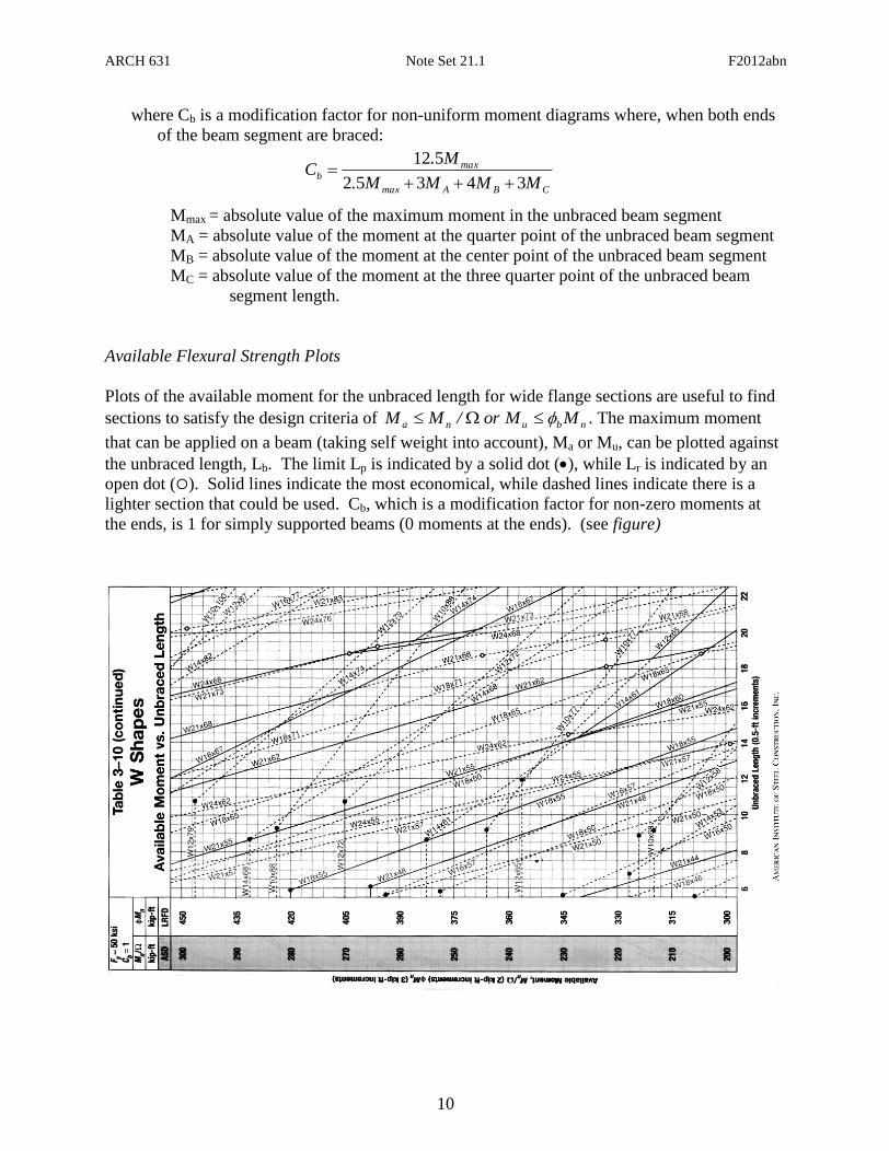
Available Flexural Strength Plots
Plots of the available moment for the unbraced length for wide flange sections are useful to find
sections to satisfy the design criteria of nbuna MMor/MM . The maximum moment
that can be applied on a beam (taking self weight into account), Ma or Mu, can be plotted against
the unbraced length, Lb. The limit Lp is indicated by a solid dot (), while Lr is indicated by an
open dot (). Solid lines indicate the most economical, while dashed lines indicate there is a
lighter section that could be used. Cb, which is a modification factor for non-zero moments at
the ends, is 1 for simply supported beams (0 moments at the ends). (see figure)
CBAmax
maxb
MMMM.
M.C
34352
512
ARCH 631 Note Set 21.1 F2012abn
11
dt
V
A
V
A
Vf
wweb
v 2
3max
Ib
VQf maxv
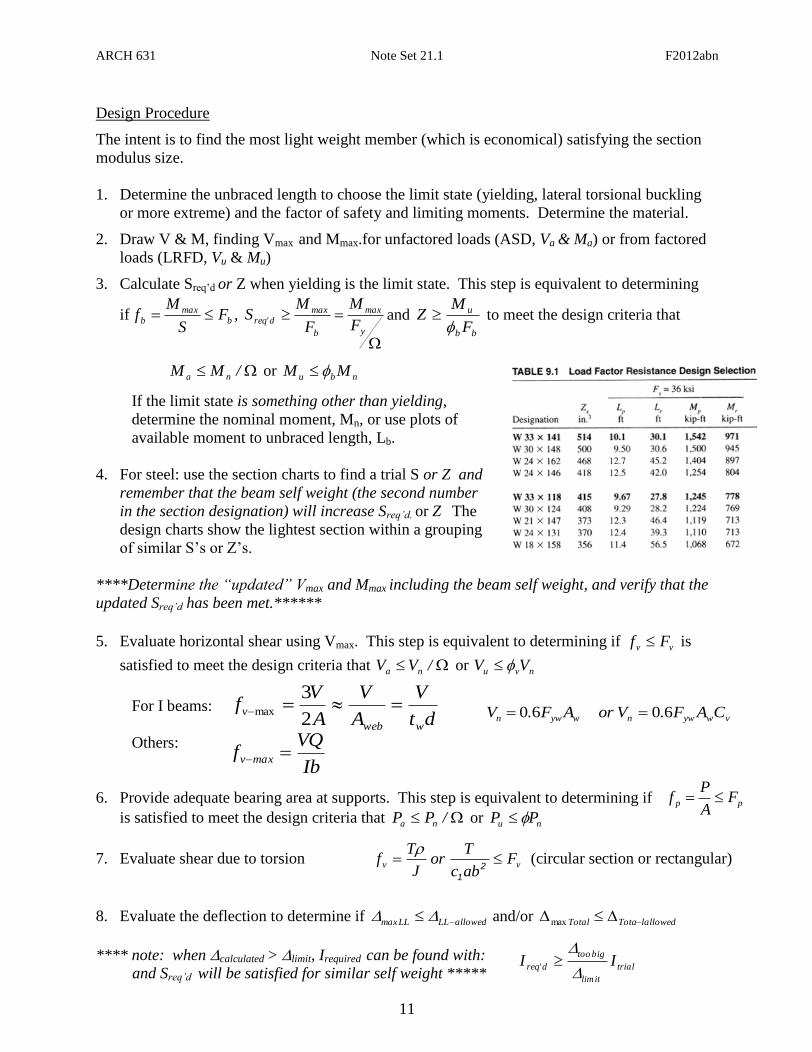
Design Procedure
The intent is to find the most light weight member (which is economical) satisfying the section
modulus size.
1. Determine the unbraced length to choose the limit state (yielding, lateral torsional buckling
or more extreme) and the factor of safety and limiting moments. Determine the material.
2. Draw V & M, finding Vmax and Mmax.for unfactored loads (ASD, Va & Ma) or from factored
loads (LRFD, Vu & Mu)
3. Calculate Sreq’d or Z when yielding is the limit state. This step is equivalent to determining
if bmax
b FS
Mf ,
y
max
b
max
d'req F
M
F
MS and
bb
u
F
MZ
to meet the design criteria that
/MM na or nbu MM
If the limit state is something other than yielding,
determine the nominal moment, Mn, or use plots of
available moment to unbraced length, Lb.
4. For steel: use the section charts to find a trial S or Z and
remember that the beam self weight (the second number
in the section designation) will increase Sreq’d. or Z The
design charts show the lightest section within a grouping
of similar S’s or Z’s.
****Determine the “updated” Vmax and Mmax including the beam self weight, and verify that the
updated Sreq’d has been met.******
5. Evaluate horizontal shear using Vmax. This step is equivalent to determining if vv Ff is
satisfied to meet the design criteria that /VV na or nvu VV
For I beams:
Others:
6. Provide adequate bearing area at supports. This step is equivalent to determining if
is satisfied to meet the design criteria that /PP na or nu PP
7. Evaluate shear due to torsion vv Fabc
Tor
J
Tf
2
1
(circular section or rectangular)
8. Evaluate the deflection to determine if allowedLLLLmax and/or lallowedTotaTotal max
**** note: when calculated > limit, Irequired can be found with:
and Sreq’d will be satisfied for similar self weight *****
trial
itlim
bigtoo
d'req II
pp FA
Pf
wywn AF.V 60 vwywn CAF.Vor 60
ARCH 631 Note Set 21.1 F2012abn
12
FOR ANY EVALUATION:
Redesign (with a new section) at any point that a stress or serviceability criteria is
NOT satisfied and re-evaluate each condition until it is satisfactory.
Load Tables for Uniformly Loaded Joists & Beams
Tables exist for the common loading situation of uniformly distributed load. The tables either
provide the safe distributed load based on bending and deflection limits, they give the allowable
span for specific live and dead loads including live load deflection limits.
If the load is not uniform, an equivalent uniform load can be calculated
from the maximum moment equation:
If the deflection limit is less, the design live load to
check against allowable must be increased, ex.
Criteria for Design of Columns
If we know the loads, we can select a section that is adequate for strength & buckling.
If we know the length, we can find the limiting load satisfying strength & buckling.
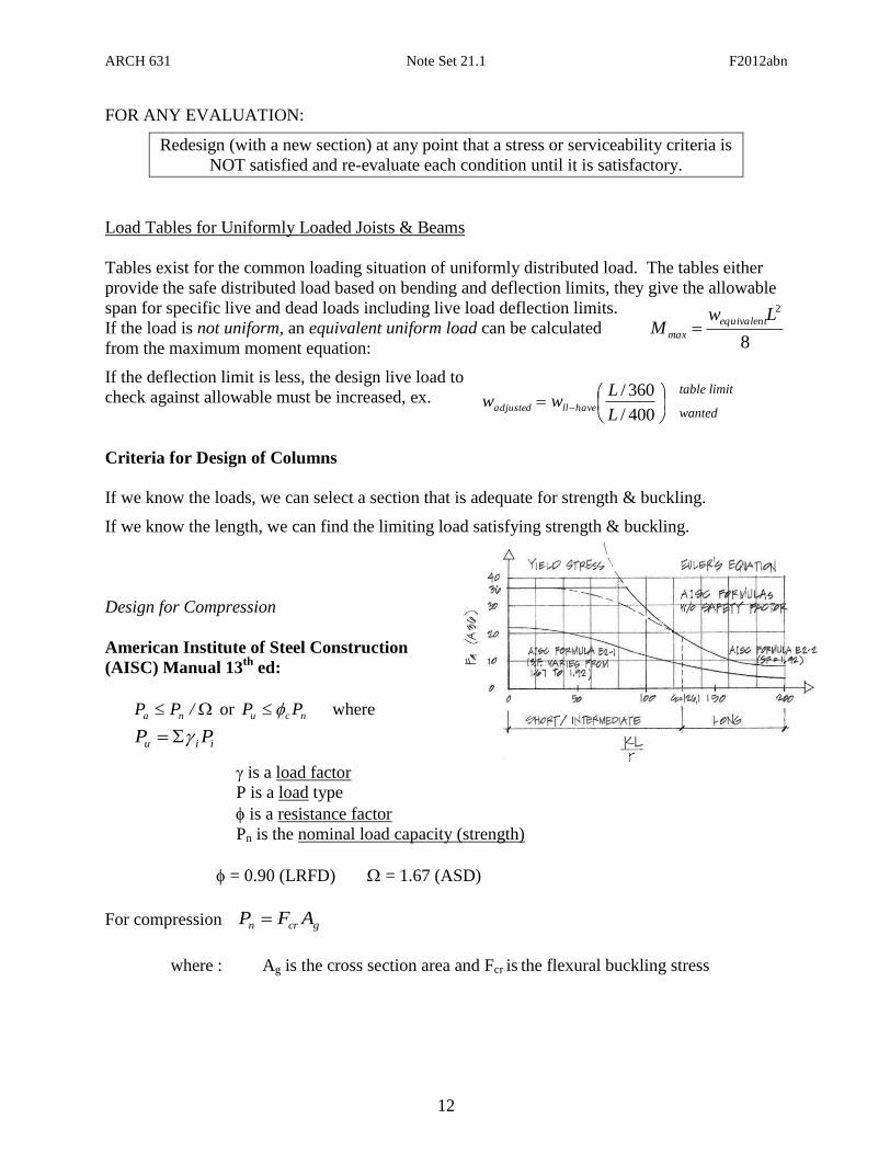
Design for Compression
American Institute of Steel Construction
(AISC) Manual 13th
ed:
/PP na or ncu PP where
iiu PP
is a load factor
P is a load type
is a resistance factor
Pn is the nominal load capacity (strength)
= 0.90 (LRFD) = 1.67 (ASD)
For compression gcrn AFP
where : Ag is the cross section area and Fcr is the flexural buckling stress
400/
360/
L
Lww havelladjusted
table limit
wanted
8
2LwM
equivalent
max

ARCH 631 Note Set 21.1 F2012abn
13
The flexural buckling stress, Fcr, is determined as follows:
when yF
E.
r
KL714 or ( ye F.F 440 ):
y
F
F
cr F.F e
y
6580
when yF
E.
r
KL714 or ( ye F.F 440 ):
ecr F.F 8770
where Fe is the elastic critical buckling stress: 2
2
rKL
EFe
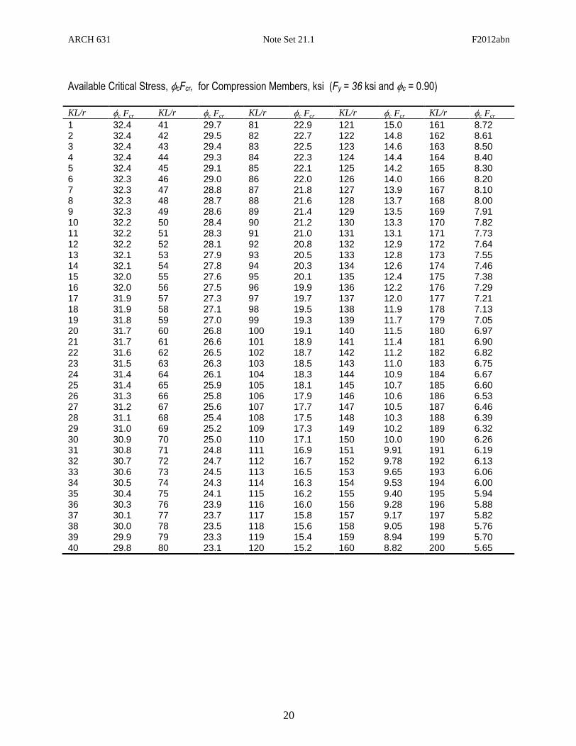
Design Aids
Tables exist for the value of the flexural buckling stress based on slenderness ratio. In addition,
tables are provided in the AISC Manual for Available Strength in Axial Compression based on
the effective length with respect to least radius of gyration, ry. If the critical effective length is
about the largest radius of gyration, rx, it can be turned into an effective length about the y axis
with the fraction rx/ry.
Sam
ple
AIS
C T
ab
le f
or
Avail
ab
le S
tren
gth
in
Axia
l
Com
pre
ssio
n
ARCH 631 Note Set 21.1 F2012abn
14
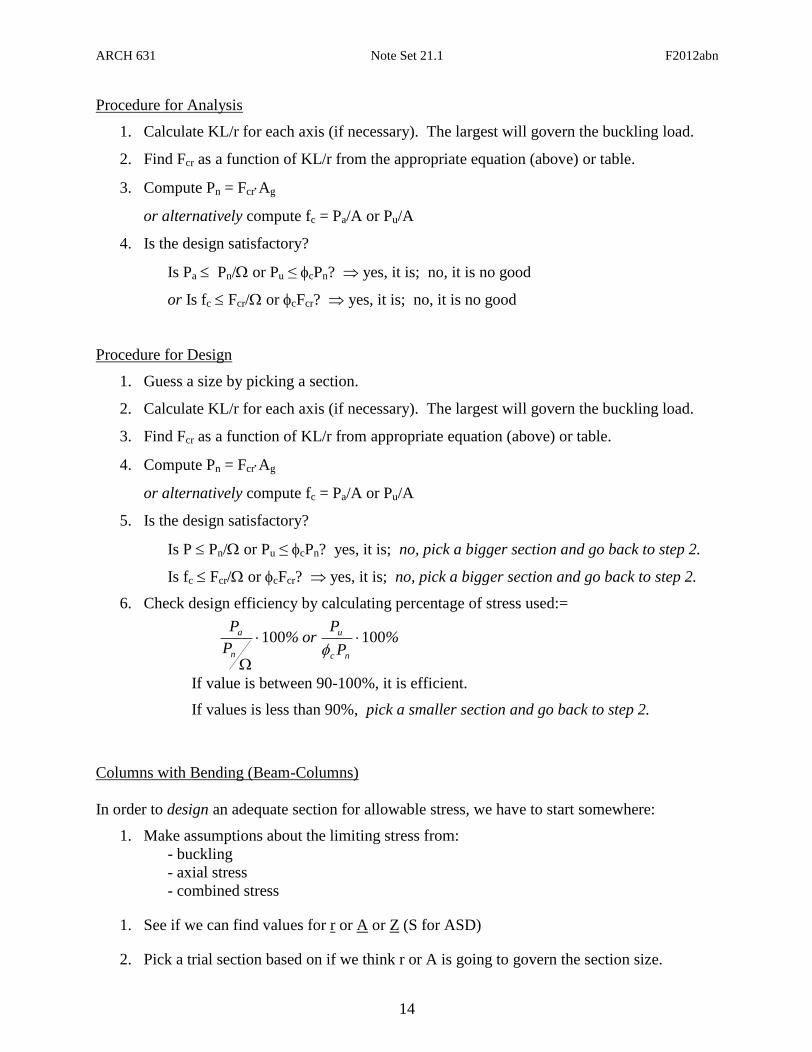
Procedure for Analysis
1. Calculate KL/r for each axis (if necessary). The largest will govern the buckling load.
2. Find Fcr as a function of KL/r from the appropriate equation (above) or table.
3. Compute Pn = FcrAg
or alternatively compute fc = Pa/A or Pu/A
4. Is the design satisfactory?
Is Pa Pn/ or Pu ≤ cPn? yes, it is; no, it is no good
or Is fc Fcr/ or cFcr? yes, it is; no, it is no good
Procedure for Design
1. Guess a size by picking a section.
2. Calculate KL/r for each axis (if necessary). The largest will govern the buckling load.
3. Find Fcr as a function of KL/r from appropriate equation (above) or table.
4. Compute Pn = FcrAg
or alternatively compute fc = Pa/A or Pu/A
5. Is the design satisfactory?
Is P Pn/ or Pu ≤ cPn? yes, it is; no, pick a bigger section and go back to step 2.
Is fc Fcr/ or cFcr? yes, it is; no, pick a bigger section and go back to step 2.
6. Check design efficiency by calculating percentage of stress used:=
If value is between 90-100%, it is efficient.
If values is less than 90%, pick a smaller section and go back to step 2.
Columns with Bending (Beam-Columns)
In order to design an adequate section for allowable stress, we have to start somewhere:
1. Make assumptions about the limiting stress from:
- buckling
- axial stress
- combined stress
1. See if we can find values for r or A or Z (S for ASD)
2. Pick a trial section based on if we think r or A is going to govern the section size.
%P
Por%
P
P
nc
u
n
a 100100

ARCH 631 Note Set 21.1 F2012abn
15
3. Analyze the stresses and compare to allowable using the allowable stress method or
interaction formula for eccentric columns.
4. Did the section pass the stress test?
- If not, do you increase r or A or S?
- If so, is the difference really big so that you could decrease r or A or S to make it
more efficient (economical)?
5. Change the section choice and go back to step 4. Repeat until the section meets the
stress criteria.
Design for Combined Compression and Flexure:
The interaction of compression and bending are included in the form for two conditions based on
the size of the required axial force to the available axial strength. This is notated as Pr (either P
from ASD or Pu from LRFD) for the axial force being supported, and Pc (either Pn/ for ASD or
cPn for LRFD). The increased bending moment due to the P-∆ effect must be determined and
used as the moment to resist.
For 20.P
P
c
r : 019
8.
M
M
M
M
P
P
ny
y
nx
x
n
0.19
8
nyb
uy
nxb
ux
nc
u
M
M
M
M
P
P
(ASD) (LRFD)
For 20.P
P
c
r : 012
.M
M
M
M
P
P
ny
y
nx
x
n
0.12
nyb
uy
nxb
ux
nc
u
M
M
M
M
P
P
(ASD) (LRFD)
where:
for compression c = 0.90 (LRFD) = 1.67 (ASD)
for bending b = 0.90 (LRFD) = 1.67 (ASD)
For a braced condition, the moment magnification factor B1 is determined by
where Cm is a modification factor accounting for end conditions
When not subject to transverse loading between supports in plane of bending:
= 0.6 – 0.4 (M1/M2) where M1 and M2 are the end moments and M1<M2. M1/M2 is
positive when the member is bent in reverse curvature (same direction), negative
when bent in single curvature.
When there is transverse loading between the two ends of a member:
= 0.85, members with restrained (fixed) ends
= 1.00, members with unrestrained ends
Pe1 =Euler buckling strength
2
2
1
rKl
EAPe
011 1
1 .)PP(
CB
eu
m
ARCH 631 Note Set 21.1 F2012abn
16
Criteria for Design of Connections and Tension Members
Refer to the specific note set.
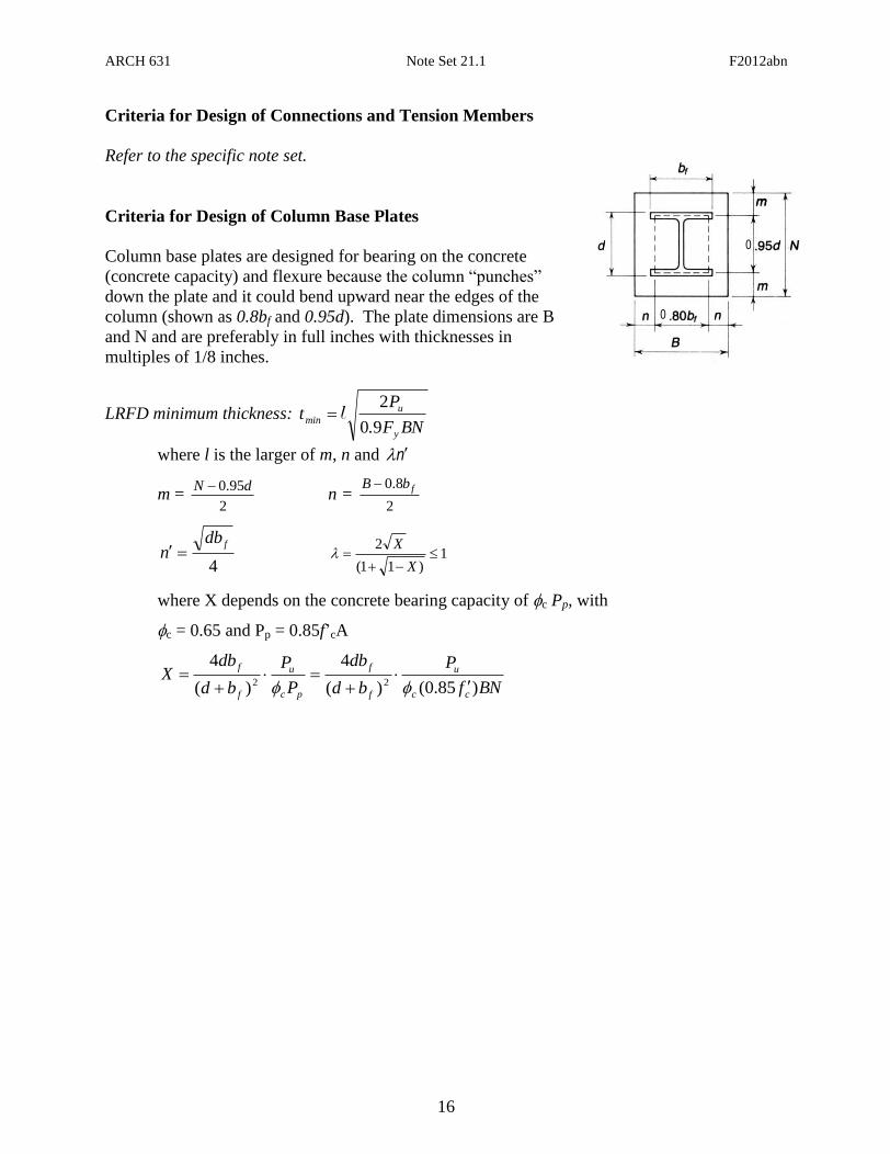
Criteria for Design of Column Base Plates
Column base plates are designed for bearing on the concrete
(concrete capacity) and flexure because the column “punches”
down the plate and it could bend upward near the edges of the
column (shown as 0.8bf and 0.95d). The plate dimensions are B
and N and are preferably in full inches with thicknesses in
multiples of 1/8 inches.
LRFD minimum thickness: BNF.
Pt
y
u
min90
2l
where l is the larger of m, n and n
m = 2
95.0 dN n =
2
8.0 fbB
4
fdbn 1
)11(
2
X
X
where X depends on the concrete bearing capacity of c Pp, with
c = 0.65 and Pp = 0.85f’cA
BNf
P
bd
db
P
P
bd
dbX
cc
u
f
f
pc
u
f
f
)85.0()(
4
)(
422
0
0
ARCH 631 Note Set 21.1 F2012abn
17
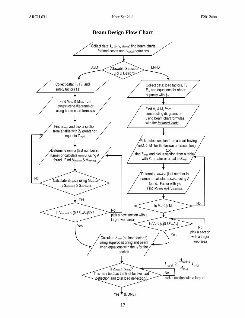
Beam Design Flow Chart
is max limits? This may be both the limit for live load deflection and total load deflection.)
Collect data: Fy, Fu, and
safety factors
Allowable Stress or LRFD Design?
ASD LRFD
Collect data: L, , , limits; find beam charts
for load cases and actual equations
Collect data: load factors, Fy, Fu, and equations for shear
capacity with V
Find Vmax & Mmax from constructing diagrams or
using beam chart formulas Find Vu & Mu from constructing diagrams or using beam chart formulas
with the factored loads
Find Zreq’d and pick a section from a table with Zx greater or
equal to Zreq’d
Determine self wt (last number in
name) or calculate self wt. using A found. Find Mmax-adj & Vmax-adj.
Calculate Sreq’d-adj using Mmax-adj.
Is Sx(picked) Sreq’d-adj?
Yes
Pick a steel section from a chart having
bMn Mu for the known unbraced length
OR
Is Vu v(0.6FywAw)
Yes
Is Vmax-adj (0.6FywAw)/.? No pick a new section with a larger web area
No pick a section with a larger
web area Calculate max (no load factors!) using superpositioning and beam chart equations with the Ix for the
section
No
pick a section with a larger Ix
Yes (DONE)
No Determine self wt (last number in
name) or calculate self wt. using A
found. Factor with D. Find Mu-max-adj & Vu-max-adj.
trial
itlim
bigtoo
d'req II
find Zreq’d and pick a section from a table with Zx greater or equal to Zreq’d
Yes
Is Mu bMn No
ARCH 631 Note Set 21.1 F2012abn
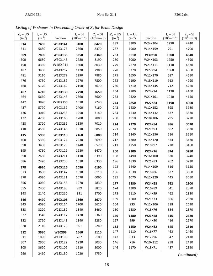
18
Listing of W shapes in Descending Order of Zx for Beam Design
Zx – US
(in.3)
Ix – US
(in.4) Section
Ix – SI
(106mm.
4)
Zx – SI
(103mm.3)
Zx – US
(in.3)
Ix – US
(in.4) Section
Ix – SI
(106mm.
4)
Zx – SI
(103mm.3)
514 7450 W33X141 3100 8420 289 3100 W24X104 1290 4740
511 5680 W24X176 2360 8370 287 1900 W14X159 791 4700
509 7800 W36X135 3250 8340 283 3610 W30X90 1500 4640
500 6680 W30X148 2780 8190 280 3000 W24X103 1250 4590
490 4330 W18X211 1800 8030 279 2670 W21X111 1110 4570
487 3400 W14X257 1420 7980 278 3270 W27X94 1360 4560
481 3110 W12X279 1290 7880 275 1650 W12X170 687 4510
476 4730 W21X182 1970 7800 262 2190 W18X119 912 4290
468 5170 W24X162 2150 7670 260 1710 W14X145 712 4260
467 6710 W33X130 2790 7650 254 2700 W24X94 1120 4160
464 5660 W27X146 2360 7600 253 2420 W21X101 1010 4150
442 3870 W18X192 1610 7240 244 2850 W27X84 1190 4000
437 5770 W30X132 2400 7160 243 1430 W12X152 595 3980
436 3010 W14X233 1250 7140 234 1530 W14X132 637 3830
432 4280 W21X166 1780 7080 230 1910 W18X106 795 3770
428 2720 W12X252 1130 7010 224 2370 W24X84 986 3670
418 4580 W24X146 1910 6850 221 2070 W21X93 862 3620
415 5900 W33X118 2460 6800 214 1240 W12X136 516 3510
408 5360 W30X124 2230 6690 212 1380 W14X120 574 3470
398 3450 W18X175 1440 6520 211 1750 W18X97 728 3460
395 4760 W27X129 1980 6470 200 2100 W24X76 874 3280
390 2660 W14X211 1110 6390 198 1490 W16X100 620 3240
386 2420 W12X230 1010 6330 196 1830 W21X83 762 3210
378 4930 W30X116 2050 6190 192 1240 W14X109 516 3150
373 3630 W21X147 1510 6110 186 1530 W18X86 637 3050
370 4020 W24X131 1670 6060 185 1070 W12X120 445 3050
356 3060 W18X158 1270 5830 177 1830 W24X68 762 2900
355 2400 W14X193 999 5820 174 1300 W16X89 541 2870
348 2140 W12X210 891 5700 173 1110 W14X99 462 2830
346 4470 W30X108 1860 5670 169 1600 W21X73 666 2820
343 4080 W27X114 1700 5620 164 933 W12X106 388 2690
333 3220 W21X132 1340 5460 160 1330 W18X76 554 2670
327 3540 W24X117 1470 5360 159 1480 W21X68 616 2620
322 2750 W18X143 1140 5280 157 999 W14X90 416 2570
320 2140 W14X176 891 5240 153 1550 W24X62 645 2510
312 3990 W30X99 1660 5110 147 1110 W16X77 462 2460
311 1890 W12X190 787 5100 147 833 W12X96 347 2410
307 2960 W21X122 1230 5030 146 716 W10X112 298 2410
305 3620 W27X102 1510 5000 146 1170 W18X71 487 2390
290 2460 W18X130 1020 4750 (continued)
ARCH 631 Note Set 21.1 F2012abn
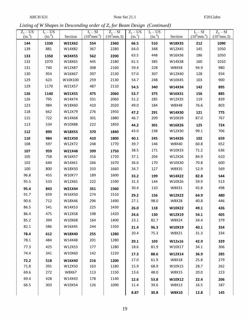
19
Zx – US
(in.3)
Ix – US
(in.4) Section
Ix – SI
(106mm.
4)
Zx – SI
(103mm.3)
Zx – US
(in.3)
Ix – US
(in.4) Section
Ix – SI
(106mm.
4)
Zx – SI
(103mm.3)
144 1330 W21X62 554 2360 66.5 510 W18X35 212 1090
139 881 W14X82 367 2280 64.0 348 W12X45 145 1050
133 1350 W24X55 562 2200 63.5 448 W16X36 186 1050
132 1070 W18X65 445 2180 61.5 385 W14X38 160 1010
131 740 W12X87 308 2160 59.4 228 W8X58 94.9 980
130 954 W16X67 397 2130 57.0 307 W12X40 128 934
129 623 W10X100 259 2130 54.7 248 W10X45 103 900
129 1170 W21X57 487 2110 54.5 340 W14X34 142 895
126 1140 W21X55 475 2060 53.7 375 W16X31 156 885
126 795 W14X74 331 2060 51.2 285 W12X35 119 839
123 984 W18X60 410 2020 49.0 184 W8X48 76.6 803
118 662 W12X79 276 1950 47.2 291 W14X30 121 775
115 722 W14X68 301 1880 46.7 209 W10X39 87.0 767
113 534 W10X88 222 1850 44.2 301 W16X26 125 724
112 890 W18X55 370 1840 43.0 238 W12X30 99.1 706
110 984 W21X50 410 1800 40.1 245 W14X26 102 659
108 597 W12X72 248 1770 39.7 146 W8X40 60.8 652
107 959 W21X48 399 1750 38.5 171 W10X33 71.2 636
105 758 W16X57 316 1720 37.1 204 W12X26 84.9 610
102 640 W14X61 266 1670 36.6 170 W10X30 70.8 600
100 800 W18X50 333 1660 34.7 127 W8X35 52.9 569
96.8 455 W10X77 189 1600 33.2 199 W14X22 82.8 544
95.5 533 W12X65 222 1590 31.3 144 W10X26 59.9 513
95.4 843 W21X44 351 1560 30.4 110 W8X31 45.8 498
91.7 659 W16X50 274 1510 29.2 156 W12X22 64.9 480
90.6 712 W18X46 296 1490 27.1 98.0 W8X28 40.8 446
86.5 541 W14X53 225 1430 26.0 118 W10X22 49.1 426
86.4 475 W12X58 198 1420 24.6 130 W12X19 54.1 405
85.2 394 W10X68 164 1400 23.1 82.7 W8X24 34.4 379
82.1 586 W16X45 244 1350 21.4 96.3 W10X19 40.1 354
78.4 612 W18X40 255 1280 20.4 75.3 W8X21 31.3 334
78.1 484 W14X48 201 1280 20.1 103 W12x16 42.9 329
77.3 425 W12X53 177 1280 18.6 81.9 W10X17 34.1 306
74.4 341 W10X60 142 1220 17.3 88.6 W12X14 36.9 285
72.2 518 W16X40 216 1200 17.0 61.9 W8X18 25.8 279
71.8 391 W12X50 163 1180 15.9 68.9 W10X15 28.7 262
69.6 272 W8X67 113 1150 13.6 48.0 W8X15 20.0 223
69.4 428 W14X43 178 1140 12.6 53.8 W10X12 22.4 206
66.5 303 W10X54 126 1090 11.4 39.6 W8X13 16.5 187
8.87 30.8 W8X10 12.8 145
Listing of W Shapes in Descending order of Zx for Beam Design (Continued)
ARCH 631 Note Set 21.1 F2012abn
20
Available Critical Stress, cFcr, for Compression Members, ksi (Fy = 36 ksi and c = 0.90) KL/r c Fcr KL/r c Fcr KL/r c Fcr KL/r c Fcr KL/r c Fcr
1 32.4 41 29.7 81 22.9 121 15.0 161 8.72 2 32.4 42 29.5 82 22.7 122 14.8 162 8.61 3 32.4 43 29.4 83 22.5 123 14.6 163 8.50 4 32.4 44 29.3 84 22.3 124 14.4 164 8.40 5 32.4 45 29.1 85 22.1 125 14.2 165 8.30 6 32.3 46 29.0 86 22.0 126 14.0 166 8.20 7 32.3 47 28.8 87 21.8 127 13.9 167 8.10 8 32.3 48 28.7 88 21.6 128 13.7 168 8.00 9 32.3 49 28.6 89 21.4 129 13.5 169 7.91 10 32.2 50 28.4 90 21.2 130 13.3 170 7.82 11 32.2 51 28.3 91 21.0 131 13.1 171 7.73 12 32.2 52 28.1 92 20.8 132 12.9 172 7.64 13 32.1 53 27.9 93 20.5 133 12.8 173 7.55 14 32.1 54 27.8 94 20.3 134 12.6 174 7.46 15 32.0 55 27.6 95 20.1 135 12.4 175 7.38 16 32.0 56 27.5 96 19.9 136 12.2 176 7.29 17 31.9 57 27.3 97 19.7 137 12.0 177 7.21 18 31.9 58 27.1 98 19.5 138 11.9 178 7.13 19 31.8 59 27.0 99 19.3 139 11.7 179 7.05 20 31.7 60 26.8 100 19.1 140 11.5 180 6.97 21 31.7 61 26.6 101 18.9 141 11.4 181 6.90 22 31.6 62 26.5 102 18.7 142 11.2 182 6.82 23 31.5 63 26.3 103 18.5 143 11.0 183 6.75 24 31.4 64 26.1 104 18.3 144 10.9 184 6.67 25 31.4 65 25.9 105 18.1 145 10.7 185 6.60 26 31.3 66 25.8 106 17.9 146 10.6 186 6.53 27 31.2 67 25.6 107 17.7 147 10.5 187 6.46 28 31.1 68 25.4 108 17.5 148 10.3 188 6.39 29 31.0 69 25.2 109 17.3 149 10.2 189 6.32 30 30.9 70 25.0 110 17.1 150 10.0 190 6.26 31 30.8 71 24.8 111 16.9 151 9.91 191 6.19 32 30.7 72 24.7 112 16.7 152 9.78 192 6.13 33 30.6 73 24.5 113 16.5 153 9.65 193 6.06 34 30.5 74 24.3 114 16.3 154 9.53 194 6.00 35 30.4 75 24.1 115 16.2 155 9.40 195 5.94 36 30.3 76 23.9 116 16.0 156 9.28 196 5.88 37 30.1 77 23.7 117 15.8 157 9.17 197 5.82 38 30.0 78 23.5 118 15.6 158 9.05 198 5.76 39 29.9 79 23.3 119 15.4 159 8.94 199 5.70 40 29.8 80 23.1 120 15.2 160 8.82 200 5.65

ARCH 631 Note Set 21.1 F2012abn
21
Available Critical Stress, cFcr, for Compression Members, ksi (Fy = 50 ksi and c = 0.90) KL/r c Fcr KL/r c Fcr KL/r c Fcr KL/r c Fcr KL/r c Fcr
1 45.0 41 39.8 81 27.9 121 15.4 161 8.72 2 45.0 42 39.6 82 27.5 122 15.2 162 8.61 3 45.0 43 39.3 83 27.2 123 14.9 163 8.50 4 44.9 44 39.1 84 26.9 124 14.7 164 8.40 5 44.9 45 38.8 85 26.5 125 14.5 165 8.30 6 44.9 46 38.5 86 26.2 126 14.2 166 8.20 7 44.8 47 38.3 87 25.9 127 14.0 167 8.10 8 44.8 48 38.0 88 25.5 128 13.8 168 8.00 9 44.7 49 37.8 89 25.2 129 13.6 169 7.91 10 44.7 50 37.5 90 24.9 130 13.4 170 7.82 11 44.6 51 37.2 91 24.6 131 13.2 171 7.73 12 44.5 52 36.9 92 24.2 132 13.0 172 7.64 13 44.4 53 36.6 93 23.9 133 12.8 173 7.55 14 44.4 54 36.4 94 23.6 134 12.6 174 7.46 15 44.3 55 36.1 95 23.3 135 12.4 175 7.38 16 44.2 56 35.8 96 22.9 136 12.2 176 7.29 17 44.1 57 35.5 97 22.6 137 12.0 177 7.21 18 43.9 58 35.2 98 22.3 138 11.9 178 7.13 19 43.8 59 34.9 99 22.0 139 11.7 179 7.05 20 43.7 60 34.6 100 21.7 140 11.5 180 6.97 21 43.6 61 34.3 101 21.3 141 11.4 181 6.90 22 43.4 62 34.0 102 21.0 142 11.2 182 6.82 23 43.3 63 33.7 103 20.7 143 11.0 183 6.75 24 43.1 64 33.4 104 20.4 144 10.9 184 6.67 25 43.0 65 33.0 105 20.1 145 10.7 185 6.60 26 42.8 66 32.7 106 19.8 146 10.6 186 6.53 27 42.7 67 32.4 107 19.5 147 10.5 187 6.46 28 42.5 68 32.1 108 19.2 148 10.3 188 6.39 29 42.3 69 31.8 109 18.9 149 10.2 189 6.32 30 42.1 70 31.4 110 18.6 150 10.0 190 6.26 31 41.9 71 31.1 111 18.3 151 9.91 191 6.19 32 41.8 72 30.8 112 18.0 152 9.78 192 6.13 33 41.6 73 30.5 113 17.7 153 9.65 193 6.06 34 41.4 74 30.2 114 17.4 154 9.53 194 6.00 35 41.1 75 29.8 115 17.1 155 9.40 195 5.94 36 40.9 76 29.5 116 16.8 156 9.28 196 5.88 37 40.7 77 29.2 117 16.5 157 9.17 197 5.82 38 40.5 78 28.8 118 16.2 158 9.05 198 5.76 39 40.3 79 28.5 119 16.0 159 8.94 199 5.70 40 40.0 80 28.2 120 15.7 160 8.82 200 5.65
Related Documents