Steam Turbine (Theory and Questions& Answers)

Welcome message from author
This document is posted to help you gain knowledge. Please leave a comment to let me know what you think about it! Share it to your friends and learn new things together.
Transcript
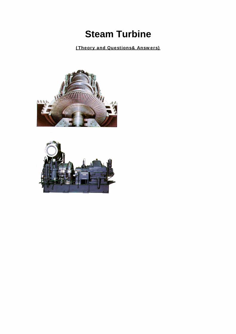
Steam Turbine
(Theory and Questions& Answers)
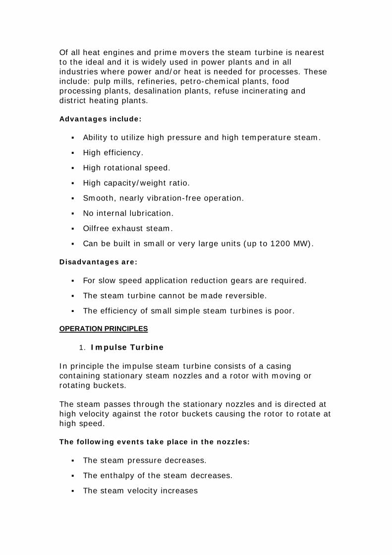
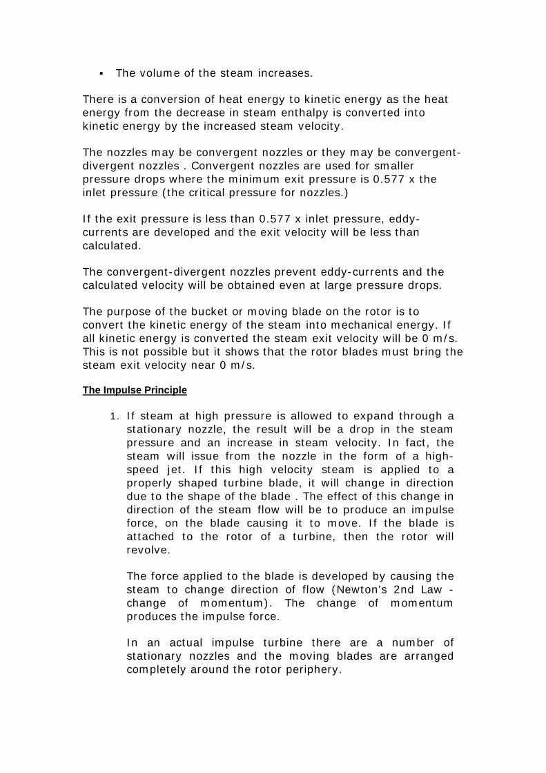
Upper casing removed. As prime mover pumps.
STEAM TURBINES
1. INTRODUCTION
Of all heat engines and prime movers the steam turbine is nearest to the ideal and it is widely used in power plants and in all industries where power and/or heat is needed for processes. These include: pulp mills, refineries, petro-chemical plants, food processing plants, desalination plants, refuse incinerating and district heating plants.
Advantages include:
Ability to utilize high pressure and high temperature steam.
High efficiency.
High rotational speed.
High capacity/weight ratio.
Smooth, nearly vibration-free operation.
No internal lubrication.
Oilfree exhaust steam.
Can be built in small or very large units (up to 1200 MW).
Disadvantages are:
For slow speed application reduction gears are required.
The steam turbine cannot be made reversible.
The efficiency of small simple steam turbines is poor.
OPERATION PRINCIPLES
1. Impulse Turbine
In principle the impulse steam turbine consists of a casing containing stationary steam nozzles and a rotor with moving or rotating buckets.
The steam passes through the stationary nozzles and is directed at high velocity against the rotor buckets causing the rotor to rotate at high speed.
The following events take place in the nozzles:
The steam pressure decreases.
The enthalpy of the steam decreases.
The steam velocity increases
The volume of the steam increases.
There is a conversion of heat energy to kinetic energy as the heat energy from the decrease in steam enthalpy is converted into kinetic energy by the increased steam velocity.
The nozzles may be convergent nozzles or they may be convergent-divergent nozzles . Convergent nozzles are used for smaller pressure drops where the minimum exit pressure is 0.577 x the inlet pressure (the critical pressure for nozzles.)
If the exit pressure is less than 0.577 x inlet pressure, eddy-currents are developed and the exit velocity will be less than calculated.
The convergent-divergent nozzles prevent eddy-currents and the calculated velocity will be obtained even at large pressure drops.
The purpose of the bucket or moving blade on the rotor is to convert the kinetic energy of the steam into mechanical energy. If all kinetic energy is converted the steam exit velocity will be 0 m/s. This is not possible but it shows that the rotor blades must bring the steam exit velocity near 0 m/s.
The Impulse Principle
1. If steam at high pressure is allowed to expand through a stationary nozzle, the result will be a drop in the steam pressure and an increase in steam velocity. In fact, the steam will issue from the nozzle in the form of a high-speed jet. If this high velocity steam is applied to a properly shaped turbine blade, it will change in direction due to the shape of the blade . The effect of this change in direction of the steam flow will be to produce an impulse force, on the blade causing it to move. If the blade is attached to the rotor of a turbine, then the rotor will revolve.
The force applied to the blade is developed by causing the steam to change direction of flow (Newton's 2nd Law - change of momentum). The change of momentum produces the impulse force.
In an actual impulse turbine there are a number of stationary nozzles and the moving blades are arranged completely around the rotor periphery.
Note that the pressure drops and the velocity increases as the steam passes through the nozzles. Then as the steam passes through the moving blades the velocity drops but the pressure remains the same.
The fact that the pressure does not drop across the moving blades is the distinguishing feature of the impulse turbine. The pressure at the inlet to the moving blades is the same as the pressure at the outlet from the moving blades.
If the moving blades of a turbine are shaped in such a way that the steam expands and drops in pressure as it passes through them, then a reaction will be produced which gives a force to the blades. This reaction effect can be illustrated by considering a container filled with high-pressure steam.
If there is no escape opening or nozzle for the steam, then the pressure will be the same on all walls of the container and the container will remain at rest. If, however, the container has an escape opening or nozzle, then steam will expand through the opening and drop in pressure. Therefore there will be an unbalanced pressure on the wall opposite to the opening and a reaction force R will be produced causing the container to move reaction Effect.
A reaction turbine has rows of fixed blades alternating with rows of moving blades. The steam expands first in the stationary or fixed blades where it gains some velocity as it drops in pressure. It then enters the moving blades where its direction of flow is changed thus producing an impulse force on the moving blades. In addition, however, the steam upon passing through the moving blades, again expands and further drops in pressure giving a reaction force to the blades.
This sequence is repeated as the steam passes through additional rows of fixed and moving blades.
Note that the steam pressure drops across both the fixed and the moving blades while the absolute velocity rises in the fixed blades and drops in the moving blades.
The distinguishing feature of the reaction turbine is the fact that the pressure does drop across the moving blades. In other words there is a pressure difference
between the inlet to the moving blades and the outlet from the moving blades.
Special Aspects of Reaction Turbines
There is a difference in pressure across the moving blades. The steam will therefore tend to leak around the periphery of the blades instead of passing through them. Blade clearances therefore must be kept to a minimum.
Also, due to pressure drop across the moving blades, an unbalanced thrust will be developed upon the rotor and some arrangement must be made to balance this.
Impulse Turbine Staging
In order for the steam to give up all its kinetic energy to the moving blades in an impulse turbine, it should leave the blades at zero absolute velocity. This condition will exist if the blade velocity is equal to one half of the steam velocity. Therefore, for good efficiency the blade velocity should be about one half of the steam velocity.
If the steam was expanded from admission pressure down to final exhaust pressure in a single set of nozzles (single stage) then the velocity of the steam leaving the nozzles might he in the order of 1100 m per second. In order to have good efficiency the blade velocity would have 10 be about 550 m per second, which would require excessively high rev/mm of the turbine rotor and failure due to centrifugal force could result.
In addition to this objection, excessively high steam velocity will cause high friction losses in nozzles and blading.
In order to reduce steam velocity and blade velocity, the following methods may be used:
Pressure compounding.
Velocity compounding.
Pressure-velocity compounding.
Pressure Compounding.
The expansion of steam from boiler pressure to exhaust pressure is carried out in a number of steps or stages. Each stage has a set of nozzles and a row of moving blades. The rows of moving blades are separated from each other by partitions or diaphragms, into which the nozzles are set. As only a portion of the velocity available is
developed in each set of nozzles, the blade velocity is kept down to a reasonable amount.
This type of compounding is known as the Rateau method.
In this arrangement, the pressure of the steam drops in each set of nozzles as indicated by the pressure graph. The steam velocity is increased by each pressure drop and then decreases again in each row of moving blades, as the velocity graph shows.
Velocity Compounding
1. This design consists of one set of nozzles in which the steam is expanded from initial to exhaust pressure. The velocity of the steam resulting from this expansion is absorbed in two or more rows of moving blades. Rows of fixed or guide blades, attached to the casing, are set between rows of moving blades and receive and redirect the steam to the next row of moving blades. As the velocity is absorbed in more than one row of moving blades, the blade speed is less than if the velocity was all absorbed in one row of blades.
This type of compounding is known as the Curtis method.
The pressure drops from inlet pressure to exhaust pressure in the single set of nozzles as the pressure graph shows. This large single pressure drop produces high steam velocity, which is absorbed in the two rows of moving blades. Note that there is no pressure or velocity drop in the fixed guide blades.
2. Pressure-Velocity Compounding
This is a combination of the first two methods of compounding, namely pressure compounding and velocity compounding.
The steam is expanded in two or more sets of nozzles in series, each set having velocity compounded blades to receive the steam issuing from the nozzles.
The steam pressure drops in each set of nozzles and the resulting velocity increase in each case is absorbed by in two rows of moving blades having a row of stationary blades between them.
The methods of reducing rotor speeds, namely, pressure compounding, velocity compounding, and pressure-velocity compounding have all applied to impulse turbines.
In the case of the reaction turbine, it is not necessary to make special blade arrangements to reduce rotor speed. This is because the pressure drops across each row of moving blades as well as across each row of fixed blades and consequently the pressure drops in even stages and small amounts all through the machine. This requires, however, a large number of alternate rows of fixed and moving blades resulting in a long machine. Therefore, in order to reduce the number of blade rows necessary, reaction turbines frequently have a velocity compounded impulse stage at the inlet end of the machine.
TYPES OF TURBINES
1. Condensing Turbines With the condensing turbine, the steam exhausts to the condenser and the latent heat of the steam is transferred to the cooling water. The condensed steam is returned to the boiler as feedwater
2. Condensing-Bleeder Turbines The condensing-bleeder turbine reduces the condenser losses as steam is bled off at several points of the turbine. The bleed-steam is used for feedwater heating; up to 20% of the total steam flow may be bled off.
3. Back-Pressure Turbines Back-pressure turbines are often used in industrial plants, the turbine acts as a reducing station between boiler and process steam header. The process steam pressure is kept constant and the generator output depends on the demand for process steam.
The backpressure turbine may also have bleed points and is then called a back-pressure-bleeder-turbine.
4. Extraction Turbines Extraction turbines are turbines where steam is extracted at one or more points at constant pressure.
Extraction turbines may be single or double-extraction-condensing turbines or single-or double-extraction back-pressure turbines. The extraction turbines may, besides extraction points, have bleed points for feedwater heating.
5. Topping Turbines Topping turbines have been used when old boilers are replaced with new high pressure boilers. The turbine is a backpressure turbine exhausting to the old boiler header still supplying steam to the old lower pressure turbines.
6. Mixed Pressure Turbines Mixed pressure turbines are used where excess steam from process is available for the low pressure part of the turbine, while steam at boiler pressure may be added to the high pressure part of the turbine when more load is applied to the turbine.
Cross Compound Turbines
Cross compound turbines are large turbines with parallel shafts with a generator on each shaft. The steam flows through the high pressure turbine, then is crossed-over to the low pressure turbine.
Tandem Compound Turbines
Tandem compound turbines are large turbines consisting of two or more turbines in series coupled together as one shaft and applied to one generator.
TURBINE PARTS
1. Turbine Casings Casings or cylinders are of the horizontal split type. This is not ideal, as the heavy flanges of the joints are slow to follow the temperature changes of the cylinder walls. However, for assembling and inspection purposes there is no other solution.
The casings are heavy in order to withstand the high pressures and temperatures. It is general practice to let the thickness of walls and flanges decrease from inlet- to exhaust-end.
Large casings for low-pressure turbines are of welded plate construction, while smaller L. P. casings are of cast iron, which may be used for temperatures up to 230°C. Casings for intermediate pressures are generally of cast carbon steel able to withstand up to 425°C. The high temperature high-pressure casings for temperatures exceeding 550°C are of cast alloy steel such as 3 Cr iMo (3% Chromium + 1% Molybdenum.)
The reason for using different casing materials is that materials at the given maximum temperatures and under constant pressure continue to deform with very slowly increasing strain of the material; this phenomenon is called "Creep".

The casing joints are made steam tight, without the use of gaskets, by matching the flange faces very exactly and very smoothly. The boltholes in the flanges are drilled for smoothly fitting bolts, but dowel pins are often added to secure exact alignment of the flange joint. The assembled casing is then machined off inside on a boring-mill, where grooves are made for the diaphragms (for impulse turbines) or for the stationary blades (reaction turbines). Borings are also made for shaft seals and in many cases for the bearings also.
For high-pressures the flanges of the casings must be very heavy and will heat up much slower than the casing walls. Flange heating, by steam through machined channels between the flanges or holes drilled axially through the upper and lower flanges, is often applied.
Double casings are used for very high steam pressures. The high pressure is applied to the inner casing, which is open at the exhaust end, letting the turbine exhaust to the outer casings the pressure is divided between the casings, and most important, the temperature is also divided of the flange and is forced to flow round the bolt by means of baffle and thermal stresses on casings and flanges are greatly reduced. Radiation losses are also decreased. The inner casing may be assembled with shrink rings giving an ideal casing without flanges.
2. Turbine Rotors The design of a turbine rotor depends on the operating principle of the turbine.
The impulse turbine with pressure drop across the stationary blades must have seals between stationary blades and the rotor. The smaller the sealing area, the smaller the leakage; therefore the stationary blades are mounted in diaphragms with labyrinth seals around the shaft. This construction requires a disc rotor.
The reaction turbine has pressure drops across the moving as well as across the stationary blades and the use of a disc rotor would create a large axial thrust across each disc. The application of a drum rotor eliminates the axial thrust caused by the discs, but not the axial thrust caused by the differential pressure across the moving blades,
3. Disc Rotors:
All larger disc rotors are now machined out of a solid forging of nickelsteel; this should give the strongest rotor and a fully balanced rotor. It is rather expensive, as the weight of the final rotor is approximately 50% of the initial forging.Older or smaller disc rotors have shaft and discs made in separate pieces with the discs shrunk on the shaft. The bore of the discs is made
0.1% smaller in diameter than the shaft. The discs are then heated until they easily are slid along the shaft and located in the correct position on the shaft and shaft key. A small clearance between the discs prevents thermal stress in the shaft.
2. Drum Rotors
The first reaction turbines had solid forged drum rotors. They were strong, generally well balanced as they were machined over the total surface. With the increasing size of turbines the solid rotors got too heavy and the hollow drum rotor was introduced. This rotor is made of two or more pieces. For good balance the drum must be machined both outside and inside and the drum must be open at one end. The second part of the rotor is the drum end cover with shaft. The end cover is made with a shrink fit and welded .
Hollow Drum Rotor
A fairly light and rigid drum rotor may be manufactured from discs welded together to form a drum. Before welding, the rotor is heated by induction heating, then the welding is performed with automatic welding machines for the "Argon-arc" process, where the arc burns in an argon atmosphere.
Most rotors are now made of nickel alloy-steels with elastic limits of around 300 x 10 pascals Rotors for high outputs and high temperatures are generally made of chromium-nickel-molybdenum steels with elastic limits of 600 - 700) x 106 pascals.
Turbine Bearings
Journal Bearings
The bearings for small turbines are often self-aligning spherical ball or roller-bearings or they may be ring lubricated sleeve bearings with bronze or babbitt lining .
2, Thrust Bearings
The main purposes of the thrust bearing are:
1, to keep the rotor in an exact position in the casing.
2, to absorb any axial thrust on the rotor.
From the thrust bearing the shaft must be free to expand in either direction, thus a shaft can have only one thrust bearing. The thrust bearing should be located at the steam inlet, where the blade clearances are most critical. When shafts of a tandem compound turbine are joined together with solid couplings, only one thrust bearing can be applied. If flexible couplings take up the axial expansion, each shaft must have a thrust bearing .
The axial thrust is very small for impulse turbines as the pressure is equal across the rotor discs ensured by equalizing holes in the discs. A simple thrust bearing such as a ball bearing for small turbines and radial babbitt facing on journal bearings for larger turbines is very common.
The pressure drop across the moving blades of reaction turbines creates a heavy axial thrust in the direction of steam flow through the turbine and a thrust bearing suitable for heavy axial loading is needed. The tilting pad Kingsbury or Michel thrust bearings operating on the same principle as the tilting pad journal bearing are generally applied. The axial thrust in impulse turbines does not require tilting pad thrust bearings, but due to their excellent performance, they are the most common thrust bearing for large impulse turbines. The axial thrust in reaction turbines can be nearly eliminated by the use of balance or dummy pistons. With the correct size of a dummy piston exposed to two different bleed point pressures, the thrust is nearly equalized, There is a small leakage across the labyrinth seal of the dummy piston as steam leaks from the high to the lower bleed point .
The axial position of the rotor is very important and an axial position indicator is often applied to the thrust bearing. It may be a large dial micrometer with alarm setting for an axial movement of 0.4 millimetre and shutdown at 0.8 millimetre, An oil pressure gage connected to an oil leak-off device may also be used as an axial position indicator .
The oil is supplied at say 500 kPa, flows through an orifice and leaks off through a nozzle The pressure between orifice and nozzle depends on the distance between the nozzle and shaft thrust collar; the larger the distance the lower the pressure. The pressure gage can be calibrated in millimetre clearance and may have alarm and shutdown settings.
Turbine Seals
1.Blade Seals
The efficiency of reaction turbines depends to a large extent on the blade seals; radial as well as axial seals are often part of the shroud with the seal clearances kept as small as possible. As protection for the axial seals some manufacturers apply an adjustable thrust bearing. The whole thrust block is cylindrical and fits like a piston in the cylinder with the whole thrust block able to be axially adjusted . During startup the thrust block is pushed against a stop in the direction of exhaust for maximum seal clearances. When the turbine is heated up and has been on load for a short time the thrust block is pulled forward against a forward stop for minimum seal clearance and maximum blade efficiency.
Shaft Seals
Shaft seals must be provided in order to prevent or at least reduce steam leakage where the shafts extend through the casings. Also when low pressure turbines are under vacuum the seals must prevent air from leaking into the casing.
Ordinary soft packing may be used for shaft sealing in small turbines. Carbon rings are also very common for small turbines. The carbon ring is made up of three segments butting together tightly under the pressure of a garter spring. The ring has a few hundreds of a millimetre clearance around the shaft and is prevented from turning by a locking pin. The ring has a slight side clearance in the housing allowing it to move freely in radial directions. Carbon rings are self-lubricating but have a tendency to corrode the shaft when the turbine is shut down. The presence of moisture accelerates the corrosion. The carbon rings are from 10 to 25 millimetres wide and may cause heating when they ride on the shaft. They are, for that reason, limited to shafts less than 150 millimetres in diameter. For larger diameter shafts where the surface speed is high, labyrinth seals are applied. The labyrinth seal consists of a number of rings (a) 1 - 2 millimetres thick fixed to the shaft, tapered at the outer periphery to nearly knife-sharp with a clearance to the casing of a few hundreds of a millimetre. The rings are of brass or stainless steel, the sharp edge gives better sealing and rubs off easily without excessive heating in case of a slightly eccentric shaft. Some labyrinth seals are very simple, others are complicated.
Carbon Ring Seal
High pressure turbines operating at 12 090 to 15 000 kPa cause a sealing problem, as a straight labyrinth seal for that pressure would be extremely long or have lots of steam leaking through. The
problem is solved by a series of steam pockets between sets of labyrinth seals. The high pressure steam leaks through 100 - 200 millimetres of labyrinth seal into the first pocket, which is connected to the H. P exhaust, thus any steam leaking through the seal is used in the I P. Turbine. After the first pocket the steam leaks through the second seal 75 -150 millimetres long and into the second pocket connected to an H.P. feedwater heater. Then steam leaks through the third labyrinth seal to the third pocket connected to the I P. exhaust. The steam then leaks through the fourth seal into the fourth pocket, which is connected to the L. P shaft seals supplying them with sealing steam. On the steam line between pocket number 4 and the L. P. seals are two connections with pressure control valves. One is a spill-over valve to the condenser, which will open to the condenser if the gland st~am exceeds the set point of a few centimetres of water above atmospheric pressure. The other connection has a control valve to supply gland steam when the pressure decreases to near atmospheric pressure. This valve operates during start-ups and low loads.
Neither the carbon nor the labyrinth shaft seals prevent all leakage. If a positive or leak-proof seal is needed, a water seal may be installed. The water seal consists of an impeller on the turbine shaft which rotates in a waterfilled casing and water thrown out from the impeller forms a leak-proof water barrier . Water seals are mainly applied to L. P glands to guard against air leakage, but they may also be applied as the final seal for H.P. and I. P. glands.
The water seal cannot operate properly at low speed and gland steam must be applied for sealing during start-up until the turbine speed is approximately 2000 rev/mm. Water seals are supplied with clean cool condensate from the extraction pump. It may be supplied directly or via a head tank with automatic level-control
The diaphragms of impulse turbines have labyrinth seals at the shaft. These seals are made of brass of stainless steel and are in six segments, each segment is springloaded and kept against a stop allowing a very small clearance between seal and shaft. In case of a bent shaft, the shaft may push the segment back against the spring pressure, preventing serious damage to shaft or seal.
Turbine Couplings
The purpose of couplings is to transmit power from the prime mover to the driven piece of machinery. For heavy loads the solid flange coupling is used . The flanges are generally integral parts of the shafts, but they may be separate parts for smaller turbines. In this case each coupling part has a tapered bore and keyway to fit the
tapered end of the shaft. Following the taper the shaft has a large thread allowing the coupling to be secured tightly with a large nut.
The friction between the coupling halves and the shear force of the bolts transmits the power. For maximum shear stress the bolts must be fitted ( ie they must fit in the holes without clearance at the shear point. The coupling bolts should be undercut, that is machined off to a diameter slightly less than the bottom diameter of the thread to avoid any strain on the thread.
In some cases the couplings must compensate for axial expansion and contraction of the rotors and in this case a flexible coupling is applied. The outer half has internal gears, while the inner part has matching external gears. The coupling works like the spline on a driveshaft for a car.
The couplings for very large shafts will need a large diameter if the bolts are used to transmit the power. The bolts can be much smaller if they are not allowed to trasnsmit power. In the coupling shear pins carry the load. The area exposed to shear is the shear pin diameter x length x number of shear pins. This design allows the shear pins to be located at a large radius from the shaft centre The coupling bolts are not fitted as they are exposed to tensile stress only.
Turbine Blades
The efficiency of the turbine depends more than anything else on the design of the turbine blades. The impulse blades must be designed to convert the kinetic energy of the steam into mechanical energy. The same goes for the reaction blades, which furthermore must convert heat energy to kinetic energy. The later years' increase in blade efficiency is due to increased aerodynamic shape calculated by computers and the milling of blades on automatic milling machines.
It is not always possible to give the blades the theoretically best profile, as several other considerations must be taken. The blade must be made strong enough to withstand high temperatures and stresses from heavy, often pulsating steam loads. There is also the stress due to centrifugal force ( for large L.P blades the centrifugal force on a single blade may exceed 200 tonnes ) Vibrations and resonant vibrations in particular must be taken into account and finally there is erosion and corrosion.
The material that comes closest to the ideal for all mentioned considerations is a chromium-nickel steel, for instance 17 Cr'13 Ni - steel.
1. Stationary Blades and Nozzles
The first set of nozzles for an impulse turbine is the control set and is divided into three to six sections with each section having a steam control valve. For smaller turbines all sections may be located in the upper half of the casing, while the sections for larger turbines cover the entire circumference. All stages following the control stage have the nozzles located in diaphragms. The diaphragms are in halves and fitted into grooves in the casing. Locking pieces in the upper part of the casing prevent the diaphragm from turning. All modern diaphragms are of an all-welded construction.
The stationary blades in reaction turbines are fitted into grooves in the casing halves; keys as shown lock the blades in place. In some cases, the blades have keys or serration on one side of the root and a caulking strip on the other side of the root is used to tighten the blades solidly in the grooves. The blades are often supplied with a shroud band with radial and/or axial sealing strips to minimize leakage losses.
The stationary blades for a Curtis wheel are attached to the casings, as are the stationary blades for reaction turbines.
When a turbine is left cold and at standstill, the weight of the rotor will tend to bend the rotor slightly. If left at standstill while the turbine is still hot, the lower half of the rotor will cool off faster than the upper half and the rotor will bend upwards "hog". In both cases, the turbine would be difficult if not impossible to start up. To overcome the problem the manufacturer supplies the larger turbines with a turning or barring gear consisting of an electric motor which through several sets of reducing gears turns the turbine shaft at low speed. The first turning gears turned the shaft at approximately 20 rev/mm, later increased to 40 and up to 60 rev/mm as proper lubrication is difficult to obtain at low speed; the same goes for the hydrogen seals of generators. Some turning gears, electric or hydraulic, turn the shaft 1 800 at set times over a period of 24 hours.
Before a cold turbine is started up it should be on the barring gear for approximately three hours. When a turbine is shut down, it should be barring for the next 24 hours. If a hydrogen cooled generator is involved the turbine should be kept on barring gear to prevent excessive loss of hydrogen, All barring gears are interlocked with a lubricating oil pressure switch and an engagement limit switch operated by the engagement handle.

Large turbines with heavy rotors are generally equipped with a jacking oil pump, supplying the lower part of the bearings with oil at approximately 10 000 kPa, thereby lifting the shaft and supplying lubricating oil.
The jacking oil is applied before start-up of the turning gears and for slow rev/mm the oil is left on, but for high rev/mm (50 - 60 rev/mm) it is generally shut down as soon as the turning gear is up to speed.
STEAM TURBINE GOVERNING
1. Nozzle Governing With nozzle governing a series of nozzle valves open in sequence as the load increases. This type of governing is most efficient and is used for impulse turbines.
2. Throttle Governing With throttle governing a single large control valve controls the load from 0% to 100%. For large turbines two control valves operating in parallel replace a large single valve.
When steam is throttled, the superheat increases and the turbine exhaust steam is drier, reducing the turbine blade erosion, but with the drier steam entering the condenser, the condenser losses increase. Throttling of steam through a valve is an isenthalpic ( constant enthalpy) process and no heat is lost. The so-called throttling losses occur in the condenser,
3. By-pass Governing or Overload Governing
This system is used on impulse as well as reaction turbines, An extra set of control valves admit steam to the space behind the Curtis wheel or for a reaction turbine to an annular space behind the first 8 - 12 stages. By-passing part of the turbine increases the turbine capacity (overloads the turbine) but at a reduced efficiency. The by-pass valves are smaller than the regular governor valves, as too much by-pass steam may starve the by-passed stages rotating in steam at very high density and the blades may overheat.
1. Turbine Governors The two general types of governors used are the speed sensitive governor and the pressure sensitive governor. Speed sensitive governors are applied to all kinds of turbines,
Pressure sensitive governors are applied to back pressure and extraction turbines in connection with the speed sensitive governor.
Speed Governing:
The frequency of 60 Hz is used as the set point or balance between supply and demand of an electric network, Any over supply of energy will increase the frequency and an under supply will decrease the frequency. The supply must at any time be equal to the demand in order to keep the frequency at exactly 60 Hz.
The speed governor is a proportional-action controller, each change in power causes a change in the turbine speed. The governor controls the opening of the control valves as a function of this speed change. Because of the governor speed droop, the frequency is not constant over the full range of load without external adjustment. Governor speed droop is the percent change in speed required for a load change equal to the rated capacity of the turbine. It is the same as % proportional band for controllers.
The speed sensitive governor may be:
a)Mechanical
b)Mechanical-hydraulic
c)Electro-hydraulic
A turbine manufacturer may use all three types depending on the size of ~e turbine; he may furthermore use several systems for each type. It is therefore impossible to describe more than a single example, such as the standard mechanical-hydraulic system applied to most Parsons turbines.
AUXILIARY OIL
Power oil at approximately 500 kPa is supplied from pump A, through overspeed relay B up to speed droop setting valve F, to main stop valve oil cylinder C and up to control valve K. The oil downstream of F is pilot oil 100 - 400 kPa) up to governor relay G and up to pilot cylinder H.
The flyballs operate the piston in the governor relay, and thereby controls the leak-off at the right end of the piston.
Assuming the turbine speed increases, the flyballs move outwards and move the relay piston to the right, increasing the leak-off and lowering the pilot oil pressure causing the piston in pilot cylinder H to move downwards. As the piston in cylinder J is stationary, the pilot piston in H will via the linkage move control piston K downwards, opening the oil drain for cylinder J and the piston in J moves downwards, but in doing so the control piston K will be moved upwards as the piston in H is stationary. When K comes back to the neutral position, oil can no longer drain out from J and the governor valve has taken up the position corresponding to the pilot oil pressure.
Turning the handwheel L clockwise will move the relay bushing to the right, decrease the leak-off, increase the pilot oil pressure for further opening of the governor valve and increasing the load. Turning L counterclockwise will reduce the turbine load.
For smaller turbines the pilot oil may be applied directly to cylinder J and K and H are omitted. The valve F is locked in a set position, but if F is opened up more, the increased oil-flow in the pilot oil system makes the system less sensitive, ie , the speed droop is increased; closing in on F decreases the speed droop.
It has been pointed out that nozzle governing is more efficient than throttle governing and that is one of the reasons for using a velocity compounded impulse wheel as control stage for an impulse reaction turbine. The second reason is that at high pressure the leakage losses around the reaction blades is excessive. Somewhere in one of the boiler lectures it was pointed out how a few extra 1~J per kg steam could increase the pressure. When we expand the steam through the turbine we find that at the high pressure a few kJ per kg steam require a large pressure drop. For instance an adiabatic expansion of steam at 12 000 kPa and 5000 C to 7000 kPa releases 170 kj/kg, but the same type of expansion from 40 kPa to 10 kPa also releases 170 kJ/kg, and that is the second reason for the combination of Curtis-Parsons.
1. Overspeed Trip
The high rotational speed of steam turbines creates large centrifugal forces, as these forces increase with the square of the speed. Therefore an absolute reliable overspeed protection must be provided.
The overspeed trip is mechanical-hydraulic and shows clearly the operating principle of all overspeed trips for turbines with hydraulic governor systems. The springloaded tripping bolt located in the turbine shaft has the centre of gravity slightly off the centre of the shaft in direction of the bolt head The nut at the end of the bolt provides a stop for the bolt in tripped position and for the tripping speed adjustment. During normal operation the main spring holds the relay rod against the tripping lever; piston A has closed the oil drain and H.P. oil passes between pistons A and B to the stop valve.
When turbine speed increases to the trip setting, usually 110% of operating speed, the centrifugal force overcomes the bolt spring, the bolt moves to the tripping position, strikes the tripping lever, unlatching the relay rod and the main spring moves the relay to the tripped position in which piston A opens the stop valve oil-port to drain, while piston B closes off the H.P. oil inlet port.
For all hydraulic systems the overspeed trip closes off for H.P. oil and opens the stop valve oil cylinder to drain allowing the valve to close under spring force.
A steam turbine based power plant consists of raising high pressure steam in a boiler from the thermal energy and expanding the steam in a turbine to generate shaft power which in turn is converted into electricity in the generator. Axial flow steam turbines consist of circularly distributed stationary blades called nozzles which direct steam on to rotating blades or buckets mounted radially on a rotating wheel. Typically, the blades are short in proportion to the radius of the wheel, and the nozzles are approximately rectangular in cross section. Several stages of expansions are obtained by using a series of nozzles and buckets, with the exhaust from the buckets of one stage flowing directly into the nozzles of the following stage. A compact machine can be built economically with ten or more stages for optimum use of high pressure steam and vacuum exhaust by mounting the wheels of a number of stages on a single shaft, and supporting the nozzles of all stages from a continuous housing. Large axial turbines must be operated under such conditions that the exhaust steam does not contain more than 10 to 13% of liquid since condensate droplets could seriously erode the high velocity nozzles and blades. The moisture content of the exhaust is dependent upon the inlet steam
pressure/temperature combination. Special moisture removal stages may be incorporated in the design when the steam superheat temperature is limited.
Steam may be utilized directly in the steam turbine without any superheat as may be done with low pressure steam, or superheated to increase the cycle efficiency. Reheat may also be included to further increase the ef ficiency of converting heat to power by superheating the steam after partial expansion and admitting the steam thus reheated back into the turbine.
QUESTION SHEET
Make a blade sketch and the steam pressure and velocity graphs for an impulse turbine with one Curtis and two Rateau stages.
Explain the following terms and list their advantages and disadvantages:
Nozzle governing
Throttle governing
By-pass governing
a ) Explain the working principle of a Kingsbury thrust bearing.
b) Explain the operating principle of an oil pressure thrust bearing position indicator.
4. The formula for centrifugal force is in x
where in mass in kg, V = velocity in metre/s
of the centre of gravity of blade
r radius to centre of gravity of blade
Using above formula find the centrifugal force in kilonewtons of a turbine blade having a mass of 4.6 kg and rotating at 3600 rev/mm when T = 1.5 metres.
5 Sketch and describe an overspeed tripping device.
6. Compare a back-pressure turbine and an extraction-condensing turbine and list their advantages and disadvantages.
7. What is the purpose of a dummy piston and what factors enter into its design?
8. Sketch a solid flange coupling and explain where it would be used.
QUESTIONS & ANSWERS ON STEAM TURBINE:
1. What is a stage in a steam turbine?
Answer:
In an impulse turbine, the stage is a set of moving blades behind the nozzle. In a reaction turbine, each row of blades is called a "stage." A single Curtis stage may consist of two or more rows of moving blades.
2. What is a diaphragm?
Answer:
Partitions between pressure stages in a turbine's casing are called diaphragms. They hold the vane-shaped nozzles and seals between the stages. Usually labyrinth-type seals

are used. One-half of the diaphragm is fitted into the top of the casing, the other half into the bottom.
3. What is a radial-flow turbine?
Answer:
In a radial-flow turbine, steam flows outward from the shaft to the casing. The unit is usually a reaction unit, having both fixed and moving blades. They are used for special jobs and are more common to European manufacturers, such as Sta-Laval (now ABB).
4. What are four types of turbine seals?
Answers:
1. Carbon rings fitted in segments around the shaft and held together by garter or retainer springs.
2. Labyrinth mated with shaft serration’s or shaft seal strips.
3. Water seals where a shaft runner acts as a pump to create a ring of water around the shaft. Use only treated water to avoid shaft pitting.
4. Stuffing box using woven or soft packing rings that are compressed with a gland to prevent leakage along the shaft.
5. In which turbine is tip leakage a problem?
Answer:
Tip leakage is a problem in reaction turbines. Here, each vane forms a nozzle; steam must flow through the moving nozzle to the fixed nozzle. Steam escaping across the tips of the blades represents a loss of work. Therefore, tip seals are used prevent this.
6. What are two types of clearance in a turbine?
Answer:
1. Radial - clearance at the tips of the rotor and casing.
2. Axial - the fore-and-aft clearance, at the sides of the rotor and the casing.
7. What are four types of thrust hearings?
Answer:
1. Babbitt-faced collar bearings.
2. Tilting pivotal pads.
3. Tapered land bearings.
4. Rolling-contact (roller or ball) bearings.
8. What is the function of a thrust bearing?
Answer:
Thrust bearings keep the rotor in its correct axial position.
9. What is a balance piston?
Answer:
Reaction turbines have axial thrust because pressure on the entering side is greater than pressure on the leaving side of each stage. To counteract this force, steam is admitted to a dummy (balance) piston chamber at the low-pressure end of the rotor. Some designers also use a balance piston on impulse turbines that have a high thrust. Instead of piston, seal strips are also used to duplicate a piston's counter force.
10. Why should a steam or moisture separator be installed in the steam line next to a steam turbine?
Answer:
All multistage turbines, low-pressure turbines, and turbines operating at high pressure with saturated steam should have a moisture separator in order to prevent rapid blade wear from water erosion.
11. What are some conditions that may prevent a turbine from developing full power?
Answers:
1. The machine is overloaded.
2. The initial steam pressure and temperature are not up to design conditions.
3. The exhaust pressure is too high.
4. The governor is set too low.
5. The steam strainer is clogged.
6. Turbine nozzles are clogged with deposits.
7. Internal wear on nozzles and blades.
12. Why is it necessary to open casing drains and drains on the steam line going to the turbine when a turbine is to be started?
Answers:
To avoid slugging nozzles and blades inside the turbine with condensate on start-up; this can break these components from impact. The blades were designed to handle steam, not water.
13. What is steam rate as applied to turbo-generators?
Answer:
The steam rate is the pounds of steam that must be supplied per kilowatt-hour of generator output at the steam turbine inlet.
14. What are the two basic types of steam turbines?
Answers:
1. Impulse type.
2. Reaction type.
15. What is the operating principle of an impulse turbine?
Answer:
The basic idea of an impulse turbine is that a jet of steam from a fixed nozzle pushes against the rotor blades and impels them forward. The velocity of the steam is about
twice as fast as the velocity of the blades. Only turbines utilizing fixed nozzles are classified as impulse turbines.
16. What is the operating principle of a reaction turbine?
Answer:
A reaction turbine utilizes a jet of steam that flows from a nozzle on the rotor. Actually, the steam is directed into the moving blades by fixed blades designed to expand the steam. The result is a small increase in velocity over that of the moving blades. These blades form a wall of moving nozzles that further expand the steam. The steam flow is partially reversed by the moving blades, producing a reaction on the blades. Since the pressure drop is small across each row of nozzles (blades), the speed is comparatively low. Therefore, more rows of moving blades are needed than in an impulse turbine.
17. What are topping and superposed turbines?
Answer:
Topping and superposed turbines arc high-pressure, non-condensing units that can be added to an older, moderate-pressure plant. Topping turbines receive high-pressure steam from new high-pressure boilers. The exhaust steam of the new turbine has the same pressure as the old boilers and is used to supply the old turbines.
18. What is an extraction turbine?
Answer:
In an extraction turbine, steam is withdrawn from one or more stages, at one or more pressures, for heating, plant process, or feedwater heater needs. They are often called "bleeder turbines."
19. What is a combination thrust and radial bearing?
Answer:
This unit has the ends of the babbitt bearing extended radially over the end of the shell. Collars on the rotor face these thrust pads, and the journal is supported in the bearing between the thrust collars.
20. What is a tapered-land thrust bearing?
Answer:
The babbitt face of a tapered-land thrust bearing has a series of fixed pads divided by radial slots. The leading edge of each sector is tapered, allowing an oil wedge to build up and carry the thrust between the collar and pad.
21. What is important to remember about radial bearings?
Answer:
A turbine rotor is supported by two radial bearings, one on each end of the steam cylinder. These bearings must be accurately aligned to maintain the close clearance between the shaft and the shaft seals, and between the rotor and the casing. If excessive bearing wear lowers the he rotor, great harm can be done to the turbine.
22. How many governors are needed for safe turbine operation? Why?
Answer:
Two independent governors are needed for safe turbine operation. One is an overspeed or emergency trip that shuts off the steam at 10 percent above running speed (maximum speed). The second, or main governor, usually controls speed at a constant rate; however, many applications have variable speed control.
23. How is a flyball governor used with a hydraulic control?
Answer:
As the turbine speeds up, the weights are moved outward by centrifugal force, causing linkage to open a pilot valve that admits and releases oil on either side of a piston or
on one side of a spring-loaded piston. The movement of the piston controls the steam valves.
24. What is a multi-port governor valve? Why is it used?
Answer:
In large turbines, a valve controls steam flow to groups of nozzles. The number of open valves controls the number of nozzles in use according to the load. A bar-lift or cam arrangement operated by the governor opens and closes these valves in sequence. Such a device is a multi-port valve. Using nozzles at full steam pressure is more efficient than throttling the steam.
25. What is meant by critical speed?
Answer:
It is the speed at which the machine vibrates most violently. It is due to many causes, such as imbalance or harmonic vibrations set up by the entire machine. To minimize damage, the turbine should be hurried through the known critical speed as rapidly as possible. (Caution, be sure the vibration is caused by critical speed and not by some other trouble).
26. How is oil pressure maintained when starting or stopping a medium-sized turbine?
Answer:
An auxiliary pump is provided to maintain oil pressure. Some auxiliary pumps are turned by a hand crank; others are motor-driven. This pump is used when the integral pump is running too slowly to provide pressure, as when starting or securing a medium-sized turbine.
27. Besides lubrication, which are two functions of lubricating oil in some turbines?
Answer:
In large units, lube oil cools the bearings by carrying off heat to the oil coolers. Lube oil in some turbines also acts
as a hydraulic fluid to operate the governor speed-control system.
28. What is meant by the water rite of a turbine?
Answer:
29. What is the difference between partial and full arc admission?
Answer:
In multi-valve turbine inlets, partial arc ad mission allows the steam to enter per valve opening in a sequential manner, so as load is increased, more valves open to admit steam. This can cause uneven heating on the high-pressure annulus as the valves are individually opened with load increase. In full-arc admission, all regulating valves open but only at a percentage of their full opening. With load increase, they all open more fully. This provides more uniform heating around the high-pressure part of the turbine. Most modern controls start with full-arc and switch to partial arc to reduce throttling losses through the valves.
30. At what points does corrosion fatigue does show up?
Answer:
It attacks trailing edges, near the base of the foil and also the blade-root serration’s.
31. Besides lubrication, what are two functions of lubricating oil in some turbines?
Answer:
In larger units, lube oil cools the bearings by carrying off heat to the oil coolers. Lube oil in some turbines also acts as a hydraulic fluid to operate the governor speed-control system.
32. But despite these preventive measures, damage due to moisture impingement has
been found, in certain cases, in the shield and beyond. Why?
Answers:
1. Shields are designed and fabricated on the basis of predicted range of steam/water quantities impacting the blades at specific angles.
2. Now if the operating conditions deviate significantly from design parameters then the erosion damage will occur. And in some cases it may go beyond nominal erosion wear and warrant repair.
3. Also the corrosion of casing can occur due to blockage/clogging of water drains or extraction thereby forcing the water back into the casing. If this condensate water is carried over to steam path and impacts the blade, thermal-fatigue failure can occur within a short period.
33. By monitoring the exhaust steam temperature, how can the blade deposition be predicted?
Answers:
1. Immediately after the 1st commissioning, the different values of exhaust temperature for different steam flow rates are precisely determined and plotted against steam flow. This will produce the first actual graph. This is for a clean turbine.
2. Similar graphs are to be drawn at later periods for comparing with the initial graph.
3. A rise in exhaust steam temperature under the same conditions refers to deposit formation.
4. An increase of exhaust steam temperature by more than 10% in the range of 70 to l00% steam flow, indicates inadmissible blade depositions. Shutdown is to be taken and blades are to be washed off deposits.
34. Do the radial axial-bore cracks occur in the LP rotor/shaft alone?
Answer:
These are also known to occur in the HP as well as HP rotors.
35. Do you stop cooling-water flow through a steam condenser as soon as the turbine is slopped?
Answer:
You should keep the cooling water circulating for about 15 mill or more so that the condenser has a chance to cool down gradually and evenly. Be sure to have cooling water flowing through the condenser before starting up in order to prevent live steam from entering the condenser unless it is cooled. Overheating can cause severe leaks and other headaches.
36. Do you think that turbine blade failure is the only cause of unreliability of steam turbines? Does upgrading of turbine means replacement of blades and/or improvement of blade design?
Answers:
1. Like the blades, the steam-turbine rotors are highly stressed components. They are subject to cracking by a variety of failure mechanisms. Rotor failures do occur. And when they occur the result is catastrophic with the complete destruction of the unit and the total loss of generating capacity.
2. Therefore, special attention should be given to rotor upgrading and repairing techniques.
37. FACTORS BLADE FAILURES
Unknown 26%
Stress-Corrosion Cracking 22%
High-Cycle Fatigue 20%
Corrosion-Fatigue Cracking 7%
Temperature Creep Rupture 6%
Low-Cycle Fatigue 5%
Corrosion 4%
Other causes 10%
TOTAL 100%
1. Besides, many damage mechanisms operate in combination of
a. poor steam/water chemistry,
b. certain blade design factors that vary from one turbine manufacture to other,
c. system operating parameters,
1. How can damaged tenons be repaired?
Answers:
By adopting modern welding techniques, tenons can be rebuilt This in some cases results in extended blade life.
2. How can problems of "excessive vibration or noise" due to piping strain be avoided on steam turbines?
Answers:
1. The inlet as well as exhaust steam lines should be firmly supported to avoid strains from being imposed on the turbine.
2. Adequate allowance should be made for expansion of steam pipes due to heat.
3. How can steam turbines be classified?
Answers:
By the action of steam:
1. Impulse.
2. Reaction.
3. Impulse and reaction combined.
The number of step reductions involved:
4. Single stage.
5. Multi-stage.
6. Whether there is one or more revolving vanes separated by stationary reversing vanes.
The direction of steam flow:
7. Axial.
8. Radial.
9. Mixed.
10. Tangential.
11. Helical.
12. Reentry.
The inlet steam pressure:
13. High pressure.
14. Medium pressure.
15. Low pressure.
The final pressure:
16. Condensing.
17. Non-condensing.
The source of steam:
18. Extraction.
19. Accumulator.
4. How can the deposits be removed?
Answers:
1. Water soluble deposits may be washed off with condensate or wet steam.
2. Water insoluble deposits are removed mechanically after dismantling the turbine.
3. Experience shows that water soluble deposits are embedded in layers of water-insoluble deposits. And when the washing process is carried out, water soluble parts of the deposit dissolve away leaving a loose, friable skeleton of water-insoluble deposits which then break loose and wash away.
5. How can the detection of deposits in a turbine be made during operation?
Answers:
1. Pressure monitoring.
2. Internal efficiency monitoring.
3. Monitoring exhaust steam temperature.
4. Monitoring specific steam consumption.
6. How can the disadvantages of the impulse turbine question 7 be overcome?
Answers:
1. Velocity compounding
2. Pressure compounding
3. Pressure-Velocity compounding.
7. How can the fatigue damage on high-pressure blades be corrected?
Answers:
Fatigue-damage on high-pressure blades arises due to vibration induced by partial-arc admission. This can be corrected by switching over to full arc admission technique.
8. How can the misalignment be rectified?
Answer:
The bolts holding the flanges together are to be tightened. The coupling is to be checked for squareness between the bore and the face. At the same time axial clearance is to be checked. Using gauge block and feeler gauges, the gap between coupling faces 1800 apart is to be measured.
After rotating the coupling-half 1800, the gap at the same points is to be measured. After this, the other coupling is to be rotated 1800 and the gap at the same points is to be re-measured. These measures should come within a few thousands of an inch. Dividing the coupling faces into four intervals, the distance between the coupling faces at this intervals is to be measured with the aid of a gauge block and feeler gauges. These gap measurements should come within 0.005 inch for proper angular shaft alignment. After proper alignment at room temperature, the two halves of the coupling are to be connected.
9. How can the problem of excessive speed variation due to throttle assembly friction be overcome?
Answer:
The throttle should be dismantled. Moving parts should be checked for free and smooth movement. Using very fine-grained emery paper, the throttle valve seats and valve steam should be polished.
10. How can the speed variation be reduced by making a governor droop adjustment?
Answer:
If the internal droop setting is increased, the speed variation will reduce.
11. How do the problems of vibration and fatigue arise with steam turbine blades?
Answers:
1. These arise due to flow irregularities introduced because of manufacturing defects, e.g. lack of control over tolerances.
2. System operating parameter, e.g. low flow may excite various modes of vibration in the blades.
12. How does deposit formation on turbine blades affect turbine efficiency?
Answer:
About 500 g of deposits distributed more or less evenly all over the blading section can bring down turbine efficiency by 1%.
13. How does improper governor lubrication arise and
Answers:
1. In the event of low governor oil level or if the oil is dirty or foamy, it will cause improper governor lubrication.
What is the remedy to it?
2. The dirty or foamy lube oil should be drained off, governor should be flushed and refilled with a fresh charge of proper oil.
3. In the event of low level, the level should be built up by make- up lube oil.
14. How does pressure monitoring ensure detection of turbine deposits?
Answers:
1. Pressure of steam expanding in the turbine is measured at characteristic points, i.e., at the wheel chamber, points of pass-out, inlet/outlet of HP, IP and LP stages of the turbine.
2. The turbine manufacturer provides the pressure characteristics in the form of graphs.
3. At 1st commissioning, the user supplements these theoretical curves with those derived from actual measurements. These are actual pressure characteristics for a clean turbine. Now these pressure characteristics are compared with those obtained during operation in the later period.
4. Under identical conditions, an increase in pressure shows the formation of deposits.
5. For a steam throughput in the range 70-100%, an increase in wheel chamber pressure of more than 10% indicates severe blade depositions.
15. How does solid-particle erosion occur?
Answer:
Solid-particle erosion, i.e. SPE occurs in the high-pressure blades. And it takes place when hard particles of iron exfoliated by steam from superheater tubes, reheater tubes, steam headers and steam leads strike on the surface of turbine blades.
16. How does the damage to turbine-blades tell upon the efficiency of the unit?
Answer:
The damage to blade profiles changes the geometry of steam flow path and thereby reducing the efficiency of the unit.
17. How does the dirty safety trip valve trip the safety trip at normal speed?
Answers:
Dirt may find its way to the safety trip valve and get deposited around the spring end cap end. This will block the clearance between the safety trip valve and the spring end cap. As a result the steam pressure in the spring cap gets lowered allowing the valve to close.
What is the remedy to it?
The spring end cap as well as safety trip valve should be cleaned.
18. How does the foreign-particle damage of turbine blades arise?
Answer:
It occurs due to impact on blades by foreign particles (debris) left in the system following outages and become steam-borne later.
19. How does the internal efficiency monitoring lead to the detection of turbine deposits?
Answers:
1. Process heat drop.
2. Adiabatic heat drop.
3. The process heat drop and adiabatic heat drop are obtained from a Mollier-Chart for the corresponding values of steam parameters - pressure and temperature - at initial and final conditions.
20. How does this modification reduce the vibration fatigue damage?
Answers:
1. Joining the blade segments together at the shroud band increases the length of the arc-to a maximum of 360° that alters the natural frequency of the blade grouping from the operating vibration mode.
2. This design has gained considerable success in commercial service.
21. How is a flyball governor used with a hydraulic control?
Answer:
As the turbine speeds up, the weights are moved outward by centrifugal force, causing linkage to open a pilot valve that admits and releases oil on either side of a piston or on one side of a spring-loaded piston. The movement of the piston controls the steam valves.
22. How is oil pressure maintained when starting or stopping a medium-sized turbine?
Answer:
An auxiliary pump is provided to maintain oil pressure. Some auxiliary pumps are turned by a hand crank; others are motor-driven. This pump is used when the integral pump is running too slowly to provide pressure, as when starting or securing a medium-sized turbine.
23. How is pressure compounding accomplished?
Answers:
1. This is accomplished by an arrangement with alternate rows of nozzles and moving blades.
2. Steam enters the 1st row of nozzles where it suffers a partial drop of pressure and in lieu of that its velocity gets increased. The high velocity steam passes on to the 1st row of moving blades where its velocity is reduced.
3. The steam then passes into the 2nd row of nozzles where its pressure is again partially reduced and velocity is again increased. This high velocity steam passes from the nozzles to the 2nd row of blades where its velocity is again reduced.
4. Thus pressure drop takes place in successive stages. Since a partial pressure drop takes place in each stage, the steam velocities will not be so high with the effect that the turbine will run slower.
24. How is pressure-velocity compounding accomplished?
Answers:
1. It is a combination of pressure compounding and velocity compounding.
2. Steam is expanded partially in a row of nozzles whereupon its velocity gets increased. This high velocity steam then enters a few rows of velocity compounding whereupon its velocity gets successively reduced.
3. The velocity of the steam is again increased in the subsequent row of nozzles and then again it is allowed to pass onto another set of velocity compounding that brings about a stage-wise reduction of velocity of the steam.
4. This system is continued.
25. How is the washing of turbine blades carried out with the condensate?
Answers:
1. The washing is carried out with the condensate at 100°C.
2. The turbine is cooled or heated up to 100°C and filled with the condensate via a turbine drain.
3. The rotor is turned or barred by hand and the condensate is drained after 2 to 4 hours.
4. It is then again filled with the condensate at 100°C (but up to the rotor center-level), the rotor is rotated and the condensate is drained after sometime. This process is repeated several times.
26. How is turbine blade washing with wet steam carried out?
Answers:
1. Wet steam produced usually by injecting cold condensate into the superheated steam, is introduced to the turbine which is kept on running at about 20% of nominal speed.
2. For backpressure turbine the exhaust steam is let out into the open air through a gate valve. For a condensing turbine, the vacuum pump is kept out of service while cooling water is running, with the effect that the entering cooling steam is condensed. The condensate is drained off.
3. The washing steam condition is gradually adjusted to a final wetness of 0.9 to 0.95.
Note, it is important:
4. not to change washing steam temperature by 10°C/min,
5. to keep all turbine cylinder drains open.
27. How is velocity compounding accomplished?
Answers:
1. This is accomplished by an arrangement with alternate rows of fixed blades and moving blades. The mounted on the casing while the
moving blades are keyed in series on a common shaft. The function of the fixed blades is to correct the direction of entry of steam to the next row of moving blades.
2. The high velocity steam leaving the nozzles passes on to the 1st row of moving blades where it suffers a partial velocity drop.
3. Its direction is then corrected by the next row of fixed blades and then it enters the 2nd row of moving blades. Here the steam velocity is again partially reduced. Since only part of the velocity of the steam is used up in each row of the moving blades, a slower turbine results. This is how velocity compounding works.
28. How many governors are needed for safe turbine operation? Why?
Answer:
Two independent governors are needed for safe turbine operation:
1. One is an overspeed or emergency trip that shuts off the steam at 10 percent above running speed (maximum speed).
2. The second, or main governor, usually controls speed at a constant rate; however, many applications have variable speed control.
29. How many types of particle-impact damage occur in turbine blades?
Answers:
1. Erosion/corrosion.
2. Foreign-particle impacts.
3. Solid-particle erosion.
4. Water damage.
30. How to prevent turbine deposition?
Answers:
By upgrading the quality of steam. That is by ensuring proper:
1. Boiler feedwater quality.
2. Steam boiler model.
3. Boiler design.
4. Boiler operation.
31. How will you detect that misalignment is the probable cause of excessive vibration?
Answers:
1. Coupling to the driven machine is to be disconnected.
2. The turbine is to be run alone.
3. If the turbine runs smoothly, either misalignment, worn coupling or the driven equipment is the cause of the trouble.
32. How would you slop a leaky tube in a condenser that was contaminating the feed-water?
Answer:
To stop a leaky tube from contaminating the feedwater, shut down, remove the water-box covers, and fill the steam space with water. By observing the tube ends you can find the leaky tube. An alternate method is to put a few pounds of air pressure in the steam space, flood the water boxes to the top inspection plate, and observe any air bubbles. Once you have found the leaky tube, drive a tapered bronze plug (coated with white lead) into each end of the tube to cut it out of service. This allows you to use the condenser since the tubes need not be renewed until about 10 percent of the tubes are plugged.
33. How would you stop air from leaking into a condenser?
Answer:
First, find the leak by passing a flame over the suspected part while the condenser is under vacuum. Leaks in the
flange joints or porous castings can be stopped with asphalt paint or shellac. Tallow or heavy grease will stop leaks around the valve stems. Small leaks around the porous castings, flange nuts, or valve stems can always be found by the flame test. So, you might have to put the condenser under a few pounds of air pressure and apply soapsuds to the suspected trouble parts.
34. In how many patterns are tie wires used?
Answers:
1. In one design, tie wire is passed through the blade vane.
2. In another design, an integral stub is jointed by welding/brazing.
35. In some weld-repair cases, it has been found that the Stellite survived while the filler material eroded away. Why?
Answers:
If Inconel is used as the filler material, it has the inferior resistance to erosion in comparison to the Stellite insert. So filler material erodes away underneath.
36. In steam turbines, is there any alternative to the shrunk-on-disc design?
Answers:
Two designs are available at present:
1. Welded rotor in which each individual disc is welded, instead of shrunk, onto the main shaft.
2. Monobloc rotor in which the entire shaft and blade assembly is manufactured from a single forging.
37. In which case does upgrading imply life extension of steam turbines?
Answer:
For a capital-short electric utility plant, upgrading comes to mean extending the life of that plant scheduled for retirement.
38. In which cases does erosion corrosion damage appear?
Answer:
It is commonly encountered in nuclear steam turbines and old fossil-fuel-fired units that employ lower steam temperatures and pressures.
39. In which cases does moisture-impingement and washing erosion occur?
Answers:
1. These are encountered in the wet sections of the steam turbine.
2. For nuclear power plants, these wet sections can involve parts of high-pressure cylinder.
40. In which cases does upgrading mean up-rating the turbine capacity?
Answer:
For an electric utility system facing uncertain load growth, upgrading is chiefly up-rating. It is an inexpensive way to add capacity in small increments.
41. In which part of the steam turbine does corrosion fatigue occur?
Answer:
In the wet stages of the LP cylinder.
42. In which part of the steam turbine does stress corrosion cracking (SCC) occur?
Answer:
In the wet stages of the low-pressure turbine.
43. In which section of the steam-turbine rotors is the problem of rotor failure mostly prevalent?
Answers:
Rotor failures occur mostly on the large low-pressure rotors.
Basic causes of the problems are:
1. Normal wear.
2. Fatigue failure due to high stress.
3. Design deficiency.
4. Aggressive operating environment
44. In which turbine is this pressure compounding used?
Answer:
In the Rateau turbine.
45. In which turbine is tip leakage a problem?
Answer:
Tip leakage is a problem in reaction turbines. Here, each vane forms a nozzle; steam must how through the moving nozzle to the fixed nozzle. Steam escaping across the tips of the blades represents a loss of work. Therefore, tip seals are used to prevent this.
46. In which turbine is velocity compounding utilized?
Answer:
In the Curtis turbine.
47. In which turbines, is this pressure-velocity compounding principle employed?
Answer:
In the Curtis turbine.
48. In which zone of steam turbines has temperature-creep rupture been observed?
Answer:
Damage due to creep is encountered in high temperature (exceeding 455°C) zones. That is, it has been found to occur in the control stages of the high-pressure and intermediate-pressure turbines where steam temperature sometimes exceed 540°C. In the reheat stage, it has been observed that creep has caused complete lifting of the blade shroud bands.
49. Is there any adverse effect off full-arc admission operation?
Answer:
At low loads, this results in a heat-rate penalty, due to throttling over the admission valves.
50. Is there any alternative to the shrunk-on-disc design?
Answers:
Two designs are available at present:
1. Welded rotor in which each individual discs are welded, instead of shrunk, onto the main shaft.
2. Monobloc rotor in which the entire shaft and blade assembly is manufactured from a single forging.
51. Is there any factor other than corrodents and erodents that contributes to turbine blade failure?
Answers:
1. Turbine blade damage and failures can be effected by vibration and fatigue.
a. These arise due to flow irregularities introduced because of manufacturing defects, e.g. lack of control over tolerances.
b. System operating parameter, e.g. low flow may excite various modes of vibration in the blades.
1. Is there any other type of racking occurring in HP/IP rotors and causing rotor failures?
Answers:
1. Blade-groove-wall cracking.
2. Rotor-surface cracking.
2. Of all the factors that contribute to the unreliability of steam turbines, which one is the most prominent?
Answer:
It is the problem of turbine blade failures that chiefly contribute to the unreliability of steam turbines.
3. Rim cracking continues to be a problem of shrunk-on-disc type rotors in utility steam turbines. Where does it occur?
Answer:
Cracking has been located at the outer corners of tile grooves where the blade root attaches to the rotor.
4. So can you recommend this technique as a permanent measure?
Answer:
No, this can be recommended in extreme cases or at best temporarily.
5. So what should be the more sound approach?
Answers:
1. The more reasonable and better approach is to replace the damaged blades with new ones that are stiffened by:
a. Serrating the interface surface of individual blades so they interlock, or
b. Welding the blades together.
c. In some cases, a single monolithic block is machined out to manufacture the blades in a group.
d. In some other cases, blades themselves are directly welded into the rotor.
1. Steam blowing from a turbine gland is wasteful. Why else should it be avoided?
Answer:
It should be avoided because the steam usually blows into the bearing, destroying the lube oil in the main bearing. Steam blowing from a turbine gland also creates condensate, causing undue moisture in plant equipment.
2. The consequences of turbine depositions have three effects?
Answers:
1. Economic Effect:
a. Reduction in turbine output
b. Decrease in efficiency requiring higher steam consumption.
1. Effect of Overloading and Decreasing Reliability in Operation:
a. Pressure characteristic in the turbine gets disturbed with the effect that thrust and overloading of thrust bearing increase.
b. Blades are subjected to higher bending stresses.
c. Natural vibrations of the blading are affected.
d. Vibration due to uneven deposition on turbine blading.
e. Valve jamming due to deposits on valve stems.
1. Corrosion Effect:
a. Fatigue corrosion.
b. Pitting corrosion.
c. Stress corrosion.
1. Usually it has been found that SCC attack takes place particularly at keyways of shrunk-on-disc rotors of low-pressure turbines. Why are keyways prone to SCC attack?
Answers:
1. Keyways shrunk-fit each disc onto tile rotor shaft. They improve the rigidity of the connection between the disc and the central shaft However, key ways are subjected to abnormal centrifugal forces due to high overspeed, that reduce the amount of shrink. Tangential stresses tend to gravitate at the keyway connection and steam tends to condense.
2. It is a one-piece-construction, and thus has inherent rigidity.
3. Advanced steel making techniques enable building of monobloc rotors almost free from non-metallic inclusions and gas bubbles. Even large monobloc rotors of clean steel are being manufactured today.
4. It exhibits lower inherent stresses.
5. The chance of disc loosening during operation is eliminated.
6. Highly stressed keyway is eliminated.
2. What are four types of thrust bearings?
Answers:
1. babbitt-faced collar bearings
2. tilting pivotal pads
3. tapered land bearings
4. rolling-contact (roller or ball) bearings
3. What are four types of turbine seals?
Answer:
1. Carbon rings fitted in segments around the shaft and held together by garter or retainer springs.
2. Labyrinths mated with shaft serrations or shaft seal strips.
3. Water seals where a shaft runner acts as a pump to create a ring of water around the shaft. Use only treated water to avoid shaft pitting.
4. Stuffing box using woven or soft packing rings that are compressed with a gland to prevent leakage along the shaft.
4. What are some common troubles in surface-condenser operation?
Answer:
The greatest headache to the operator is loss of vacuum caused by air leaking into the surface condenser through the joints or packing glands. Another trouble spot is cooling water leaking into the steam space through the ends of the tubes or through tiny holes in the tubes. The tubes may also become plugged with mud, shells, debris, slime, or algae, thus cutting down on the cooling-water supply, or the tubes may get coated with lube oil from the reciprocating machinery. Corrosion and dezincification of the tube metal are common surface-condenser troubles. Corrosion may be uniform, or it may occur in small holes or pits. Dezincification changes the nature of the metal and causes it to become brittle and weak.
5. What are the advantages of steam turbines over reciprocating steam engines?
Answers:
1. Steam turbine has higher thermal efficiency than reciprocating steam engines.
2. The brake horsepower of steam turbines can range from a few HP to several hundred thousand HP in single units. Hence they are quite suitable for large thermal power stations.
3. Unlike reciprocating engines, the turbines do not need any flywheel, as the power delivered by the turbine is uniform.
4. Steam turbines are perfectly balanced and hence present minimum vibrational problem.
5. High rpm l8000 - 24000 can be developed in steam turbines but such a high speed generation is not possible in the case of reciprocating steam engines.
6. Some amount of input energy of steam is lost as the reciprocating motion of the piston is converted to circular motion.
7. Unlike reciprocating steam engines, no internal lubrication is required for steam turbines due to the absence of rubbing parts.
8. Steam turbines, if well designed and properly maintained, are more reliable and durable prime movers than steam engines.
6. What are the advantages of velocity compounding?
Answers:
1. The velocity compounding system is easy to operate and operation is more reliable.
2. Only two or three stages are required. Therefore, first cost is less.
3. Since the total pressure drop takes place only in nozzles and not in the blades, the turbine casing need not be heavily built. Hence the economy in material and money.
4. Less floor space is required.
7. What are the advantages of welded rotors?
Answers:
1. Welded rotor is a composed body built up by welding the individual segments. So the limitations on forgings capacity do not apply.
2. Welding discs together results in a lower stress level. Therefore, more ductile materials can be chosen to resist SCC attack.
3. There are no keyways. So regions of high stress concentrations are eliminated.
8. What are the basic causes of the problem of rotor failure?
Answers:
1. Normal wear.
2. Fatigue failure due to high stress.
3. Design deficiency.
4. Aggressive operating environment
9. What are the causes of radial axial-bore cracks on HP/IP rotors/shafts?
Answers:
1. The predominant cause is creep, which may act with or without low cycle fatigue.
2. Also the cracks result due to poor creep ductility due to faulty heat treatment process.
10. What are the differences between impulse and reaction turbines?
Answers:
1. The impulse turbine is characterized by the fact that it requires nozzles and that the pressure drop of steam takes place in the nozzles.
2. The reaction turbine, unlike the impulse turbines has no nozzles, as such. It consists of a row of blades mounted on a drum. The drum blades are separated by rows of fixed blades mounted in the turbine casing. These fixed blades serve as nozzles as well as the means of correcting the direction of steam onto the moving blades.
3. In the case of reaction turbines, the pressure drop of steam takes place over the blades. This pressure drop produces a reaction and hence cause the motion of the rotor.
11. What are the disadvantages of velocity compounding?
Answers:
1. Steam velocity is too high and that is responsible for appreciable friction losses.
2. Blade efficiency decreases with the increase of the number of stages.
3. With the increase of the number of rows, the power developed in successive rows of blade decreases. For as much as, the same space and material are required for each stage, it means, therefore, that all stages are not economically efficient.
12. What are the factors that contribute to bearing failure in a steam turbine?
Answers:
1. Improper lubrication.
Only the recommended lubricant should be used.
2. Inadequate water-cooling.
a. The jacket temperature should be maintained in the range of 37-60°C
b. The flow of cooling water should be adjusted accordingly.
1. Misalignment.
It is desirable that ball bearings should fit on the turbine shaft with a light press fit. If the fitting is too tight, it will cause cramping. On the other hand, if the fitting is too loose it will cause the inner race to turn on the shaft. Both conditions are undesirable. They result in wear, excessive vibration and overheating. And bearing failure becomes the ultimate result.
2. Bearing fit.
3. Excessive thrust.
4. Unbalance.
5. Rusting of bearing.
1. What are the losses in steam turbines?
Answers:
1. Residual Velocity Loss - This is equal to the absolute velocity of the steam at the blade exit.
2. Loss due to Friction - Friction loss occurs in the nozzles, turbine blades and between the steam and rotating discs. This loss is about 10%.
3. Leakage Loss.
4. Loss due to Mechanical Friction - Accounts for the loss due to friction between the shaft and bearing.
5. Radiation Loss - Though this loss is negligible, as turbine casings are insulated, it occurs due to heat leakage from turbine to ambient air which is at a much lower temperature than the turbine.
6. Loss due to Moisture - In the lower stages of the turbine, the steam may become wet as the velocity of water particles is lower than that of steam. So a part of the kinetic energy of steam is lost to drag the water particles along with it.
2. What are the main causes of turbine vibration?
Answer:
1. unbalanced parts
2. poor alignment of parts
3. loose parts
4. rubbing parts
5. lubrication troubles
6. steam troubles
7. foundation troubles
8. cracked or excessively worn parts
3. What are the points of SCC attack?
Answers:
1. SCC attack predominates where corrodents deposit and build up i.e. in those blading areas
where flowing steam cannot provide a washing effect.
2. What are these points in particular?
a. Tie wires.
b. Tie wire holes.
c. Brazings.
d. Blade covers.
e. Tenon holes.
1. At what points does corrosion fatigue does show up?
It attacks trailing edges, near the base of the foil and also the blade-root serration’s.
1. What are the possible causes for the turbine not running at rated speed?
Answers:
1. The possible causes are:
a. too many hand valves closed,
b. oil relay governor set too low,
c. inlet steam pressure too low or exhaust pressure too high,
d. load higher than turbine rating,
e. throttle valve not opening fully,
f. safety trip valve not opening properly,
g. nozzles plugged,
h. steam strainer choked.
1. What are the possible causes of a governor not operating?
Answers:
1. Restriction of throttle valve reflex.
2. Failure of governor control on start-up.
If it is found that after start-up, the speed increases continuously and the governor is not closing the throttle valve, it may be that the governor pump has been installed in the wrong direction.
2. What are the possible causes of excessive vibration or noise in a steam turbine?
Answers:
1. Misalignment.
2. Worn bearings.
3. Worn coupling to driven machine.
4. Unbalanced coupling to driven machine.
5. Unbalanced wheel.
6. Piping strain.
7. Bent shaft.
3. What are the possible causes of the speed of the turbine rotor increasing excessively as the load is decreased?
Answers:
1. Throttle valve not closing fully.
2. Wearing of throttle valve seats.
4. What are the stresses to which a steam turbine rotor is subjected during its service life?
Answers:
1. Mechanical stress - The factors that contribute to mechanical stress in the shaft are the centrifugal forces and torque’s generated due to revolving motion of the shaft as well as bending arising during steady-state operation.
2. Thermal stress - Transient operating phases i.e. startup and shutdown the genesis of thermal stress induced to the turbine shaft.
3. Electrically induced stress - They originate due to short circuits and faulty synchronization.
5. What are these points in particular?
Answers:
1. Tie wires.
2. Tie wire holes.
3. Brazings.
4. Blade covers.
5. Tenon holes.
6. What are three types of condensers?
Answer:
1. surface (shell-and-tube)
2. jet
3. barometric.
7. What are topping and superposed turbines?
Answer:
Topping and superposed turbines are high-pressure, non-condensing units that can be added to an older, moderate-pressure plant. Topping turbines receive high-pressure steam from new high-pressure boilers. The exhaust steam of the new turbine is at the same pressure as the old boilers and is used to supply the old turbines.
8. What are two types of clearance in a turbine?
Answers:
1. radial - the clearance at the tips of the rotor and casing
2. axial - the fore-and-aft clearance, at the sides of the rotor and the casing
9. What design modification is adopted to reduce susceptibility of last low-pressure stages to fatigue failure?
Answer:
One modification is to join the blade segments together at the shroud band.
10. What does "upgrading" generally means in the context of steam turbines?
Answer:
Upgrading is a most widely used tern. It encompasses a variety of meanings verses life extension, modernization and up-rating of steam turbines.
11. What does the term "ramp rat" mean?
Answer:
Ramp rate is used in bringing a turbine up to operating temperature and is the degrees Fahrenheit rise per hour that metal surfaces are exposed to when bringing a machine to rated conditions. Manufactures specify ramp rates for their machines in order to avoid thermal stresses. Thermocouples are used in measuring metal temperatures.
12. What factors are responsible for turbine-blade failures?
Answers:
1. In the high pressure cylinder, the turbine blades are mostly affected by:
a. solid-particle erosion (SPE),
b. high cycle fatigue,
1. Whereas in the last few stages of the low-pressure cylinder, the blade damage is mainly afflicted by:
a. erosion,
b. corrosion,
c. stress/fatigue damage mechanism.
d. According to EPRI (Electric Power Research Institute, USA) data stress-corrosion cracking and fatigue are the chief exponents for turbine-blade failures in utility industries.
1. What factors cause excessive steam leakage under carbon rings?
Answers:
1. Dirt under rings. - steam borne scale or dirt foul up the rings if steam is leaking under the carbon rings.
2. Shaft scored.
3. Worn or broken carbon rings.
These should be replaced with a new set of carbon rings. The complete ring is to be replaced.
2. What factors contribute to excessive speed variation of the turbine?
Answers:
1. Improper governor droop adjustment.
2. Improper governor lubrication.
3. Throttle assembly friction.
4. Friction in stuffing box.
5. High inlet steam pressure and light load.
6. Rapidly varying load.
3. What is a balance piston?
Answer:
Reaction turbines have axial thrust because pressure on the entering side is greater than pressure on the leaving side of each stage. To counteract this force, steam is admitted to a dummy (balance) piston chamber at the low-pressure end of the rotor. Some designers also use a balance piston on impulse turbines that have a high thrust. Instead of pistons, seal strips are also used to duplicate a piston's counter force.
4. What is a combination thrust and radial bearing?
Answer:
This unit has the ends of the babbitt bearing extended radially over the end of the shell. Collars on the rotor face these thrust pads, and the journal is supported in the bearing between the thrust collars.
5. What is a diaphragm (turbine)?
Answer:
Partitions between pressure stages in a turbine's casing are called diaphragms. They hold the vane-shaped nozzles and seals between the stages. Usually labyrinth-type seals are used. One-half of the diaphragms are fitted into the top of the casing, the other half into the bottom.
6. What is a multiport governor valve? Why is it used?
Answer:
In large turbines, a valve controls steam flow to groups of nozzles. The number of open valves controls the number of nozzles in use according to the load. A bar-lift or cam arrangement operated by the governor, opens and close the valves in sequence. Such a device is a multiport valve. Using nozzles at full steam pressure is more efficient than throttling the steam.
7. What is a radial-flow turbine?
Answer:
In a radial-flow turbine, steam flows outward from the shaft to the casing. The unit is usually a reaction unit, having both fixed and moving blades. They are used for special jobs and are more common to European manufacturers.
8. What is a shrunk-on-disc rotor?
Answer:
These are built by heat expanding the discs, so that upon cooling they shrink on the main rotor forging.
9. What is a stage in a steam turbine?
Answer:
In an impulse turbine, the stage is a set of moving blades behind the nozzle. In a reaction turbine, each row of blades is called a "stage." A single Curtis stage may consist of two or more rows of moving blades.
10. What is a tapered-land thrust bearing?
Answer:
The babbitt face of a tapered-land thrust bearing has a series of fixed pads divided by radial slots. The leading edge of each sector is tapered, allowing an oil wedge to build up and carry the thrust between the collar and pad.
11. What is an air ejector?
Answer:
An air ejector is a steam siphon that removes non-condensable gases from the condenser.
12. What is an extraction turbine?
Answer:
In an extraction turbine, steam is withdrawn from one or more stages, at one or more pressures, for heating, plant process, or feedwater heater needs. They are often called "bleeder turbines."
13. What is combined-cycle cogeneration?
Answer:
A combined cycle using a gas turbine or diesel, usually driving a generator in which the exhaust gases are directed to a waste heat-recovery boiler or heat-recovery steam generator (HRSG). The steam from the HRSG is then directed to a steam turbo-generator for additional electric power production. The use of the exhaust heat from a gas turbine improves the overall thermal efficiency. In cogeneration, electric power is produced, but part of the steam from the HRSG or from extraction from the steam turbine is used for process heat, hence the term cogeneration-the simultaneous production of electric power and process heat steam.
14. What is done when cracks due to SCC or corrosion-fatigue are found?
Answer:
The damaged blade is usually replaced, as repairing is difficult.
15. What is gland-sealing steam?
Answer:
Low-pressure steam is led to a sealing gland. The steam seals the gland, which may be a carbon ring or of the labyrinth type, against air at the vacuum end of the shaft.
16. What is important to remember about radial bearings?
Answer:
A turbine rotor is supported by two radial bearings, one on each end of the steam cylinder. These bearings must be accurately aligned to maintain the close clearances between the shaft and the shaft seals, and between the rotor and the casing. lf excessive bearing wear lowers the rotor, great harm can be done to the turbine.
17. What is meant by critical speed?
Answer:
It is the speed at, which the machine vibrates most violently. It is due to many causes, such as imbalance or harmonic vibrations set up by the entire machine. To minimize damage, the turbine should be hurried through the known critical speed as rapidly as possible.
Caution: Be sure the vibration is caused by critical speed and not by some other trouble.
18. What is meant by the water rate of a turbine?
Answer:
It is the amount of water (steam) used by the turbine in pounds per horsepower per hour or kilowatts per hour.
19. What is the cause of axial-bore cracks?
Answer:
Inadequate toughness of rotor steel and transient thermal stresses.
20. What is the cause of circumferential cracking?
Answer:
High cycle fatigue with or without corrosion.
21. What is the cause of turbine deposits?
Answers:
The turbine deposits are steam-born foreign matters settled on turbine blades. Substances dissolved in the BFW transfer partly from the water to steam, during the process of evaporation. They get dissolved in the steam and are carried into the steam turbine.
22. What is the definition of a steam turbine?
Answers:
A steam turbine is a prime mover that derives its energy of rotation due to conversion of the heat energy of steam into kinetic energy as it expands through a series of nozzles mounted on the casing or produced by the fixed blades.
1. Neilson defines it: The turbine is a machine in which a rotary motion is obtained by the gradual change of the momentum of the fluid.
2. Graham's definition: The turbine is a prime mover in which a rotary motion is obtained by the centrifugal force brought into action by changing the direction of a jet of a fluid (steam) escaping from the nozzle at high velocity.
23. What is the difference between partial and full arc admission?
Answer:
In multi-valve turbine inlets, partial arc admission allows the steam to enter per valve opening in a sequential manner, so as load is increased, more valves open to admit steam. This can cause uneven heating on the high-pressure annulus as the valves are individually opened with load increase. In full-arc admission, all regulating valves open but only at a percentage of their full opening. With load increase, they all open more fully. This provides more uniform heating around the high-pressure part of the turbine. Most modern controls start with full-arc and switch to partial arc to reduce throttling losses through the valves.
24. What is the essential distinguishing feature between a steam turbine and reciprocating steam engine?
Answers:
1. In a steam turbine, the heat energy of steam is converted into kinetic energy by allowing it to expand through a series of nozzles and this kinetic energy of steam is then imparted to the turbine blades mounted on a shaft free to rotate to drive this prime mover.
2. In a reciprocating steam engine, the pressure energy of steam is directly utilized to overcome the external resistance. Here, the utilization of the KE of input steam is negligibly small.
25. What is the function of a gland drain?
Answer:
The function of a gland drain is to draw off water from sealing-gland cavities created by the condensation of the sealing steam. Drains are led to either the condenser air-ejector tube nest or the feedwater heaters. Often, gland drains are led to a low-pressure stage of the turbine to extract more work from the gland-sealing steam.
26. What is the function of a thrust bearing?
Answer:
Thrust bearings keep the rotor in its correct axial position.
27. What is the harm if the rotor is oversped?
Answer:
Overspeed rotor grows radially causing heavy rub in the casing and the seal system. As a result, considerable amount of shroud-band and tenon-rivet head damage occurs.
28. What is the nature of circumferential cracking in shrunk-on-disc rotors in steam turbines?
Answer:
Regions of high stress concentration give birth to this type of cracking. It begins in corrosion pits and propagates towards the bore by high-cycle fatigue. It may culminate in a catastrophe, if it penetrates the bore (happily this usually does not occur).
29. What is the nature of rotor surface cracks in steam turbines?
Answer:
They are shallow in depth and have been located in heat grooves and other small radii at labyrinth-seal areas along the rotor.
30. What is the operating principle of a reaction turbine?
Answer:
A reaction turbine utilizes a jet of steam that flows from a nozzle on the rotor. Actually, the steam is directed into the moving blades by fixed blades designed to expand the steam. The result is a small increase in velocity over that of the moving blades. These blades form a wall of moving nozzles that further expand the steam. The steam flow is partially reversed by the moving blades, producing a reaction on the blades. Since the pressure drop is small
across each row of nozzles (blades), the speed is comparatively low. Therefore, more rows of moving blades are needed than in an impulse turbine.
31. What is the possible cause of slow start up of a steam turbine?
Answer:
This may be due to high starting torque required by the driven equipment.
32. What is the potential problem of shrunk-on-disc type rotor?
Answers:
1. It is the failure due to circumferential cracks, which are not limited to old rotors of early models (1960), but they also take place on present-day rotors.
2. As a result corrodent impurities like chlorides concentrate at key ways. This factor coupled with high stress concentration lead to SCC attack on keyway areas.
33. What is the principle of a steam turbine?
Answers:
1. If high-velocity steam is allowed to blow on to a curved blade, the steam will suffer a change in direction as it passes across the blade, and leaves it as shown.
2. As a result of its change in direction across the blade, the steam will impart a force to the blade. This force will act in the direction shown.
3. Now if the blade were free in the direction of force as depicted. if, therefore, a number of blades were fixed on the circumference of a disc which is free to rotate on a shaft, then steam blown across the blades in the way described, would cause the disc to rotate. This is the working principle of a steam turbine.
34. What is the purpose of a turning gear?
Answer:
Heat must be prevented from warping the rotors of large turbines or high-temperature turbines of 400°C or more. When the turbine is being shut down, a motor-driven turning gear is engaged to the turbine to rotate the spindle and allow uniform cooling.
35. What is the remedy for a bent steam turbine shaft causing excessive vibration?
Answers:
1. The run-out of the shaft near the center as well as the shaft extension should be checked.
2. If the run-out is excessive, the shaft is to be replaced.
36. What is the remedy for rotor-surface cracking?
Answer:
Current rotor/shaft should be machined off (skin-peeling).
37. What is the remedy of the damage to blade profiles?
Answers:
1. Upgrading the turbine and depending on the extent of damage, upgrading may involve:
a. weld repair of affected zones of the blade,
b. replacement of damaged blades by new ones and of new design,
c. replacement of base material,
d. application of protective coatings to guard against corrosion and erosion damage.
1. What are the remedies to this failure?
Answers:
2. For existing rotor, weld repair may be a choice; otherwise retire it.
3. For new rotors, materials with improved pitting resistance should be used.
1. What is the safe maximum tripping speed of a turbine operating at 2500 rpm?
Answer:
The rule is to trip at 10 percent overspeed. Therefore, 2500 x 1.10 = 2750 rpm.
2. What is the solution to the problem of SCC/corrosion fatigue of steam turbine blades?
Answer:
It involves changing the blade material as well as minimizing the presence of corrodents in steam to a permissible level.
3. What is to be done for erosion-induced damage on high-and low-pressure stage blading?
Answers:
1. In such cases welding repair can be a good solution and this can be carried out during a normal maintenance outage without removing the blade. Using oxyacetylene torch, Stellite is generally deposited onto the damaged site. Following this, the weld is subjected to stress-relieving and re-profiling.
2. In case of erosion penetrating the erosion shield and extending to the base material, a filler material of consistent or identical composition of blade material is used.
3. In some cases use is made of Inconel alloy to build up the metal base. Therefore, using welding or brazing technique, a new shield can be attached to the blade. If brazing technique is followed, the rebuilt section is stress-relieved prior to the attachment of shield to it. If, on the other hand, the shield is attached by welding, then they are stress-relieved together.

4. What is to be done in case of cracks originating at the lacing-wire holes?
Answers:
1. These are to be weld-repaired. However the following factors must be considered:
a. The length of the crack that appears on the pressure and/or suction face.
b. Whether the cracks propagate towards inlet end, discharge end and or both.
1. What maybe the possible causes for the safety trip to trip at normal speed?
Answers:
1. Excessive vibration.
2. Leakage in the pilot valve.
3. Deposition of dirt in the safety trip valve.
2. What maybe the possible causes for the safety trip tripping during load variation?
Answers:
1. Light load and high inlet steam pressure.
2. Safety trip set very close to the operating speed of turbine.
3. What other parts of the steam turbine blades suffer from damage?
Answers:
1. Blade roots.
2. Shroud band.
4. What provisions in the layout of a combined-cycle should be considered?
Answer:
It is important to consider the use of a bypass stack that will permit operating the gas turbo-generator in case of a
forced outage on the HRSG or steam turbo-generator. However, in certain states, such as California, also to be considered are NO limits that require steam injection and loading to limit the exhaust temperature coming out of the simple-cycle gas turbine so that they do not exceed jurisdictional limits.
5. What remedial measures you can suggest to cope with radial axial-bore cracks?
Answer:
For new rotors, modified heat treatment process is recommended while for existing rotors de-rating the turbine or replacement of the rotor may be a solution.
6. What should be done if excessive vibration is due to an unbalanced turbine wheel?
Answers:
1. The turbine wheel is to be checked if it became unbalanced due to overspeeding.
2. The turbine wheel must be re-balanced or replaced.
3. What should be the remedial action?
Answers:
4. For new rotors, control cleanliness of the steel.
5. i.e. inclusion and segregates free and more homogeneous steel shaft is required.
6. For current rotors, replace the rotor, grind and overbore.
7. What should be the remedial actions for blade-groove-wall cracking?
Answers:
1. Modified heat treatment of new rotors is a sound and lasting remedy.
2. For current rotors, cracks should be machined off and lighter blades should be installed. Better, retire the cracked shaft.
8. What should you do if you lost vacuum while operating a condensing turbine plant?
Answer:
If vacuum is lost shut down immediately. The condenser cannot stand steam pressure; the condenser tubes may leak from excessive temperature. Excessive pressure will also damage the shell, the exhaust, and the low-pressure parts of the turbine.
9. What steps are taken to minimize damage from moisture on steam turbine blades?
Answers:
The following measures are employed at the design stage:
1. Stellite inserts.
2. Hardening of the base metal.
3. Moisture-removal devices to combat impingement corrosion due to moisture.
10. What steps are taken to minimize damage from moisture?
Answers:
1. Stellite inserts.
2. Hardening of the base metal.
3. Moisture-removal devices to combat impingement corrosion due to moisture.
11. What steps/modifications should be implemented to curtail the damage from moisture impingement on steam turbine blades?
Answers:
1. The drainage system should be redesigned. Larger drains are to be provided.
2. More effective water-catchers are to be in-stalled.

3. Radial seals are to be eliminated to remove water before it can chance upon the blades.
4. Nozzle trailing edges are to be thinned to promote the formation of smaller and less harmful droplets.
12. What steps/modifications should be implemented to curtail the damage from moisture impingement?
Answers:
1. The drainage system should be redesigned. Larger drains are to be provided.
2. More effective water-catchers are to be in-stalled.
3. Radial seals are to be eliminated to remove water before it can chance upon the blades.
4. Nozzle trailing edges are to be thinned to promote the formation of smaller and less harmful droplets.
13. What type of deposits are formed on steam turbine blading?
Answers:
1. Water-soluble deposits.
a. NaCl, Na2SO4, NaOH and Na3PO4
1. Water-insoluble deposits.
a. SiO2 (mainly).
1. What types of cracking occur in the LP rotor shaft?
Answers:
1. Radial axial-bore cracks.
2. Circumferential cracks.
2. When "stall flutter" occurs?
Answers:
This problem is encountered when operating limits are exceeded i.e., when turbine exhaust pressure exceeds the value what the manufacturer has recommended. Stall flutter induces stress in the blades
3. When does SPE damage usually occur on steam turbine blades?
Answer:
It occurs usually during startup or abrupt load change.
4. When does SPE damage usually occur?
Answer:
It occurs usually during startup or abrupt load change.
5. When does upgrading mean modernization of utility industry?
Answer:
Upgrading is really modernization to all those units other than those facing uncertain load growth and low-capital utility system. It involves replacement of damaged parts/components by state-of-the-art components without scrapping the entire machine.
6. Where are velocity compounded steam turbines mostly employed?
Answers:
1. They are chiefly used as the prime mover for:
a. Centrifugal pumps.
b. Centrifugal compressors.
c. Low capacity turbo-generators.
d. Feed pumps of high capacity power plants.
1. Where do water-soluble deposits prevail?
Answer:

In the high-and intermediate-pressure sections of steam turbines.
2. Where is pitting corrosion mostly prevalent?
Answer:
Upstream of LP stages as well as wet stages of LP cylinder.
3. Where would you look for a fault if the air ejector did not raise enough vacuum?
Answer:
In this case, the trouble is usually in the nozzle. You will probably find that:
1. the nozzle is eroded
2. the strainer protecting the nozzle is clogged
3. the steam pressure to the nozzle is too low
4. Which factors affect the extent of an upgrading program?
Answers:
1. Age of the unit.
2. How it has been operated.
Note: Turbines less than quarter of a century old can simply be upgraded to their original design conditions.
5. Why are free-standing blades in the last low-pressure stage favored more, in some cases, than those that are coupled and shrouded together?
Answers:
1. These free-standing blades are known to provide good and adequate protection against stresses and aggressive environment.
2. They eliminate all areas viz. shroud/tenon interface and tie-wire/hole area where corrodents can collect
6. Why are simple impulse turbines not so common?
Answers:
1. Since the whole pressure drop from boiler to condenser pressure takes place in a single row of nozzles, the velocity of the steam entering the turbine is very high. If some of this velocity is used up in a single row of turbine blading, as in the de Laval turbine, the speed of the rotation of the wheel will be too high to be blades are be useful for practical purposes, as there is the danger of structural failures due to excessive centrifugal stresses.
2. Steam exits from the turbine with a sufficiently high velocity, meaning a considerable loss of kinetic energy.
7. Why are some groups of steam turbine blades, particularly the first or control stages more prone to fatigue failures than others?
Answer:
Blades in the first or control stages are under partial-arc admission that forces the blades to move into and out of the steam flow causing alternating high-and low-impact forces. This periodic change of impact forces imparts fatigue stress that makes such groups of blades susceptible to fatigue failure.
8. Why could a turbine wheel become unbalanced?
Answer:
If the turbine is kept idle for a long spell without complete drainage of exhaust casing, the solid matter can deposit in the lower half of the wheel causing unbalance.
9. Why do blade roots suffer from damage?
Answers:
1. Fatigue is the common cause to the effect of blade root damage. Also a generic type of fault
often assists this factor in design or manufacturer.
2. Moreover, the root-fillet radii are subjected to a high degree of stress concentration with the effect that they crack relatively easily.
10. Why do electrically induced stresses occur in steam turbine rotors occur?
Answer:
They originate due to short circuits and faulty synchronization.
11. Why do shroud bands suffer from damage?
Answer:
Steam borne solid particles and moisture strike the shroud band continually and in that process they remove material from rivet heads until the rivet becomes too weak to exercise its clamping effect whereupon it fails to hold the band in place.
12. Why do thermal stress occur in the steam turbine rotors?
Answer:
Transient operating phases i.e. startup and shutdown the genesis of thermal stress induced to the turbine shaft.
13. Why do these two types of cracking take place?
Answers:
1. The cause to the effect of blade-groove-wall cracking is creep with or without low cycle fatigue.
2. Faulty heat treatment procedure results in poor creep ductility that may also contribute to this type of faults.
3. Whereas thermal fatigue have been identified as the single cause to rotor-surface cracking.
14. Why does mechanical stress occur in turbine rotors?
Answer:
The factors that contribute to mechanical stress in the shaft are the centrifugal forces and torque’s generated due to revolving motion of the shaft as well as bending arising during steady-state operation.
15. Why does SCC occur at the intermediate pressure stage in the steam turbine?
Answer:
Steam turbines of nuclear power plants usually operate on wetter steam, than those of thermal power plants. So even at the intermediate pressure stage, steam becomes wet and it precipitates the impurities i.e. corrodents dissolved in it These corrodents deposit and build up on rotor shaft causing stress-corrosion-cracking.
16. Why is it poor practice to allow turbine oil to become too cool?
Answer:
If the turbine oil is allowed to become too cool, condensation of atmospheric moisture takes place in the oil and starts rust on the polished surfaces of the journals and bearings. Condensed moisture may also interfere with lubrication.
17. Why is there a relief valve on a turbine casing?
Answer:
The turbine casing is fitted with spring-loaded relief valves to prevent damage by excessive steam pressure at the low-pressure end if the exhaust valve is closed accidentally. Some casings on smaller turbines are fitted with a sentinel valve, which serves only to warn the operator of overpressure on the exhaust end. A spring-loaded relief valve is needed to relieve high pressure.
18. Why must condensate be subjected to salinity tests where brackish cooling water is used?
Answer:
Condensate may leak from the cooling-water side to the steam side of the condenser and contaminate the feedwater, thus causing scale to form in the boilers. Or brackish cooling water may leak into the steam space from cracked or porous lubes or from around the joints at the end of the tube ends, etc. By taking salinity readings of the condensate, leaks may be found before they can do any harm.
19. Why must steam turbines be warmed up gradually?
Answer:
Although it is probable that a turbine can, if its shaft is straight, be started from a cold condition without warming up, such operation does not contribute to continued successful operation of the unit. The temperature strains set up in the casings and rotors by such rapid heating have a harmful effect. The turbine, in larger units especially, should be warmed slowly by recommended warm-up ramp rates because of close clearances.
20. Why were cracks at the bore common for high-pressure and intermediate-pressure rotors of the early sixties in steam turbines?
Answers:
1. These rotors were manufactured from forgings which were not "clean" steel and that's why cracks were initiated at the sites of inclusions, and
2. Segregation bands in the steel. This coupled with low inherent toughness of rotor materials resulted in bore cracks.
STEAM TURBINES AUXILLARIES:
1. Where is an evaporative condenser used in practice?
Answer:
In those cases where the shortage of cooling water is acute.
2. What should be the basic criteria for an efficient steam condenser?
Answers:
1. Maximum amount of steam condensed per unit area of available heat transfer surface.
2. Minimum quantity of circulating coolant required.
3. Minimum heat transfer surface required per kW capacity
4. Minimum power drawn by the auxiliaries.
3. Why must a vacuum be maintained in the steam condenser?
Answers:
1. By maintaining a vacuum in the steam condenser, the efficiency of the steam-power plant can be increased as greater the vacuum in the system, greater will be the enthalpy drop of steam. Therefore, more work will be available per kg of steam condensing.
2. Secondly, the non-condensate (air) can be removed from the condensate-steam circuit by pulling and maintaining a vacuum in the steam side. Therefore, the condensate can be used as boiler feed.
4. What are the limitations of a surface condenser?
Answers:
1. It is very bulky and as such requires more floor space.
2. Its manufacturing, running and maintenance costs are high.
5. What should be the requirements of an ideal surface condenser used for steam power plants?
Answers:
1. Uniform distribution of exhaust steam throughout the heat transfer surface of the condenser.
2. Absence of condensate subcooling.
3. There should not be any leakage of air into the condenser.
4. There should not be any tube leakage.
5. The heat transfer surface in contact with cooling water must be free from any deposit as scaling reduces the efficiency of heat exchangers.
6. What do you mean by vacuum?
Answer:
Vacuum means any pressure below atmospheric pressure.
7. How is vacuum in a condenser usually measured?
Answer:
It is measured by means of a Bourdon pressure gauge, which is calibrated to read the pressure in mm of mercury below atmospheric pressure.
8. On what factors does the degree of vacuum in a condenser depend?
Answers:
It depends on the partial pressure of steam and the partial pressure of air in the condenser.
9. What is the vacuum efficiency of a condenser?
Answers:
It is the ratio of the actual vacuum at the steam inlet to the maximum obtainable vacuum in a perfect condensing plant, i.e., it is the ratio of actual vacuum to ideal vacuum.
10. What are the effects of air leakage in the condenser?
Answers:
1. It increases the back pressure on the turbine with the effect that there is less heat drop and low thermal efficiency of the plant
2. The pressure of air in the condenser lowers the partial pressure of steam, which means steam, will condense at a lower temperature and that will require greater amount of cooling water.
3. It reduces the rate of condensation of steam, because air having poor thermal conductivity impairs the overall heat transfer from the steam-air mixture.
11. What is a steam condenser?
Answers:
1. It is a heat exchanger wherein steam is condensed either in direct contact with cooling water or indirect contact with cooling water through a heat transfer medium separating them.
2. That is, a steam condenser is either a direct contact or indirect contact heat exchanger.
12. How many types of steam condensers are known?
Answers:
1. Jet Condensers - direct contact heat exchanger.
2. Surface Condensers - indirect contact heat exchanger.
13. What is a surface condenser?
Answer:
It is a shell-and-tube heat exchanger in which steam is condensed on the shell-side while cooling water flows through the tubes. The condensate and cooling water leave the system separately.
14. How does the down-flow type surface condenser act?
Answer:
Exhaust steam is admitted to the top of the condenser, which is a tube-and-shell type crossflow heat exchanger. Cooling water flows through the tubes and extracts heat from the steam, which is on the shell-side. Mter having been condensed on the surface of the water tubes, steam is converted into condensate which is discharged from the condenser bottom.
15. How does the central flow type surface condenser work?
Answer:
It is also a shell-and-tube type crossflow heat exchanger at the center of which is located the suction of an air extraction pump, so that the entire steam moves radially inward and comes in better contact with the outer surface of the nest of tubes through which the cooling water flows. The steam condensate is extracted from the bottom by the condensate-extraction pump.
16. How does the inverted type surface condenser work?
Answer:
In this type of condenser, steam is admitted at the bottom and flows upwards in cross-flow with the cooling water flowing in the tubes. The air extraction pump draws its suction from the top of the condenser, maintaining a steady upward current of steam, which after having been condensed on the outer surface of water tubes is removed by the condensate extraction pump.
17. How does the evaporative condenser function?
Answer:
Exhaust steam from the turbine is condensed inside the finned tubes as cooling water rains down from the top through the nozzles. A part of the cooling water in contact with the tube surface evaporates by drawing enthalpy from the steam, which upon losing its latent heat condenses and discharges out as condensate.
18. What are the primary functions of a condenser?
Answers:
There are two important functions of a condenser:
1. It reduces the back pressure upon the turbine by a considerable degree and therefore, the work done per kg of steam during expansion is increased
2. The exhaust steam condensate can be recycled as boiler feedwater
19. Why else is steam from an HRSG used?
Answer:
For steam injection into the gas turbine for NOx control.
20. What gas is used in the SCR method of controlling NOx?
Answer:
Air-diluted ammonia vapor is injected into the flue gas stream before it enters the catalyst units consisting of honeycomb-shaped ceramic material. These cells, with the ammonia vapor, convert nitrogen oxides to nitrogen and water vapor for discharge into the atmosphere.
21. What is a steam condenser?
Answers:
1. It is a heat exchanger wherein steam is condensed either in direct contact with cooling water or indirect contact with cooling water
through a heat transfer medium separating them.
2. That is, a steam condenser is either a direct contact or indirect contact heat exchanger.
22. How many types of steam condenser are known?
Answers:
1. Jet Condensers - direct contact heat exchanger.
2. Surface Condensers - indirect contact heat exchanger using water.
3. Air Condensers - direct contact heat exchangers using air.
23. What is a jet condenser?
Answers:
1. It is a direct contact heat exchanger in which steam to be condensed comes into direct contact with the cooling water (cold condensate) which is usually introduced in the form of a spray from a jet.
2. Upon contact with the cooling water, the steam gives up its enthalpy and gets cooled and ultimately settles as condensate.
24. What is a surface condenser?
Answer:
It is a shell-and-tube heat exchanger in which steam is condensed on the shell-side while cooling water flows through the tubes. The condensate and cooling water leave the system separately.
25. How many types of jet condensers are known?
Answers:
1. Parallel flow jet type condenser - It is a kind of jet condenser in which both exhaust steam
and cooling water enter the condenser at the top, both flow downward and the steam condensate discharges out from the bottom of the condenser.
2. Contra flow type jet condenser - The cooling fluid (cold condensate) and exhaust steam flow in a counter-current direction - steam goes up and cold condensate rains down.
3. Ejector type jet condenser - It is one kind of jet condenser in which the mixing of cooling water and steam takes place in a series of combining cones and the kinetic energy of the steam is expended to drain off the condensate and cooling water from the condenser. Cooling water is forced through a series of cones and gets mixed with steam coming through ports. As the cooling water flows through the series of nozzles, it suffers more and more pressure drop and at the same time its velocity gradually increases. Due to this pressure drop, more and more steam is drawn through the ports, gets intimately mixed with the cooling water jet and condenses thereafter.
26. What is the principle of operation of a high-level-parallel-flow jet condenser?
Answer:
This condenser, also called barometric condenser, works as follows - The condenser is mounted on a long pipe (at least 10.34 m) called barometric leg which acts in a way identical to a barometer. Now if water is used in a barometer then the barometric height would be 10.34 m. If some vacuum exists in the condenser, the height of water column (h) will be less than 10.34 in. Now it is possible, by using this condenser leg, to drain away the condensate from the condenser.
27. How many types of surface condensers are known?
Answers:
1. Down flow type - Exhaust steam is admitted to the top of the condenser, which is a tube-and-shell type cross flow heat exchanger. Cooling water flows through the tubes and extracts heat from the steam which is on the shell-side. After having been condensed on the surface of the water tubes, steam is converted into condensate, which is discharged from the condenser bottom.
2. Central flow type - It is also a shell-and-tube type cross flow heat exchanger at the center of which is located the suction of an air extraction pump so that the entire steam moves radially inward and comes in better contact with the outer surface of the nest of tubes through which the cooling water flows. The steam condensate is extracted from the bottom by the condensate-extraction pump.
3. Inverted flow type - In this type of condenser, steam is admitted at the bottom and flows upwards in cross-flow with the cooling water flowing in the tubes. The air extraction pump draws its suction from the top of the condenser, maintaining a steady upward current of steam, which after having been condensed on the outer surface of water tubes is removed by the condensate extraction pump.
4. Evaporative condenser type - Exhaust steam from the turbine is condensed inside the finned tubes as cooling water rains down from the top through the nozzles. A part of the cooling water in contact with the tube surface evaporates by drawing enthalpy from the steam, which upon losing its latent heat condenses and discharges out as condensate.
28. Where is the evaporative condenser used in practice?
Answers:
In those cases where the shortage of cooling water is acute.
29. What are the two prime functions of a condenser?
Answers:
1. It reduces the backpressure upon the turbine by a considerable degree and therefore, the work done per kg of steam during expansion is increased.
2. The exhaust steam condensate can be recycled as boiler feedwater.
30. What are the auxiliary equipment required for operating a steam condenser?
Answers:
1. Cooling water (which may be cold condensate) circulation pump. Generally, it is a centrifugal one.
2. Arrangement for cooling the condensate (i.e., a heat exchanger) in case the condensate is recycled to extract heat from the exhaust steam.
3. An air pump or steam ejector to remove air and other non-condensing gases from the condenser.
4. An extraction pump (usually centrifugal) to remove the condensate from the condenser.
31. What should be the basic criteria for an efficient steam condenser?
Answer:
1. Maximum amount of steam condensed per unit area of available heat transfer surface.
2. Minimum quantity of circulating coolant required.
3. Minimum heat transfer surface required per kW capacity.
4. Minimum power drawn by the auxiliaries.
32. Why is vacuum maintained in the steam condenser?
Answers:
1. By maintaining a vacuum in the steam condenser, the efficiency of the steam-power
plant can be increased as greater the vacuum in the system, greater will be the enthalpy drop of steam. Therefore, more work will be available per kg of steam condensing.
2. Secondly, the non-condensate (air) can be removed from the condensate-steam circuit by pulling and maintaining a vacuum in the steam side. Therefore, the condensate can be used as boiler feed.
33. What are the advantages of a jet condenser over a surface condenser?
Answers:
1. Simplicity in design.
2. Lower in manufacturing cost.
3. Lower maintenance cost.
4. Occupies lesser floor space.
5. Requires lesser amount of cooling water.
34. What are the advantages of a surface condenser over a jet condenser?
Answers:
1. It imparts to power generation plant a higher thermal efficiency.
2. The condensate can be reused as boiler feedwater.
3. Auxiliary power requirement is less than that of a jet condenser.
4. Less amount of air is carried to the boiler.
35. What are the limitations of a surface condenser?
Answers:
1. It is very bulky and as such requires more floor space.
2. Its manufacturing, running and maintenance costs are high.
36. What should be the requirements of an ideal surface condenser used for steam power plants?
Answers:
1. Uniform distribution of exhaust steam throughout the heat transfer surface of the condenser.
2. Absence of condensate subcooling.
3. There should not be any leakage of air into the condenser.
4. There should not be any tube leakage.
5. The heat transfer surface in contact with cooling water must be free from any deposit as scaling reduces the efficiency of heat exchangers.
37. What do you mean by vacuum?
Answer:
Vacuum means any pressure below atmospheric pressure.
38. How is vacuum in a condenser usually measured?
Answers:
It is measured by means of a Bourdon pressure gauge, which is calibrated to read the pressure in mm of mercury below atmospheric pressure.
39. If the gauge pressure of a condenser is 630 mm of Hg, what will be the absolute pressure in the condenser?
Answer:
It means the pressure in the condenser is 630 mm below atmospheric pressure. The atmospheric pressure is 760 mm of Hg, the absolute pressure in the condenser.
40. On what factors does the degree of vacuum in a condenser depend?
Answer:
It depends on the partial pressure of steam and the partial pressure of air in the condenser.
41. How could air enter the condenser?
Answers:
1. With the boiler feedwater as dissolved gases.
2. Flange leakage.
3. Cooling water (for jet condenser) containing a certain amount of dissolved air in it.
42. What are the effects of air leakage in the condenser?
Answers:
1. It increases the backpressure on the turbine with the effect that there is less heat drop and low thermal efficiency of the plant.
2. The pressure of air in the condenser lowers the partial pressure of steam, which means steam, will condense at a lower temperature and that will require greater amount of cooling water.
3. It reduces the rate of condensation of steam, because air having poor thermal conductivity impairs the overall heat transfer from the steam-air mixture.
43. What basic governor troubles are apt to occur?
Answers:
1. Hunting-alternate speeding and slowing of the engine, which means that the governor is too sensitive to load changes.
2. Sticking-failure to control speed, allowing the engine to run away or slow down-which means that the governor is not sensitive to load changes or parts are binding or worn.
44. What is a governor safety stop?

Answers:
On throttling-type governors, the safety stop is a weighted arm that needs the support of a governor belt. If the belt breaks, the idler arm drops and shuts the steam supply valve to the engine. On Corliss units, the flyballs fall to the lowest position and knock off the safety cams; the cams disengage the catch blocks on the steam intake valves so that no steam is admitted to the engine.
45. Why is condensation or excessive carryover dangerous to reciprocating engines?
Answer:
Because water is non-compressible. If an excessive amount of water gets into the cylinder, it will wreck the engine.
46. Why should a steam or moisture separator be installed in the steam line next to a steam turbine?
Answer:
All multistage turbines, low-pressure turbines, and turbines operating at high pressure with saturated steam should have a moisture separator in order to prevent rapid blade wear from water erosion.
47. Under what conditions may a relief valve not be required on the exhaust end of a turbine?
Answer:
If the manufacturer has provided that the turbine shells are constructed for full-inlet steam pressure for the entire length of the shell. It is absolutely essential to have a relief valve to protect the shell in the event an exhaust valve is closed and high-pressure steam is admitted to the shell on the front end of the machine. Explosions have occurred when this happened.
48. What are some conditions that may prevent a turbine from developing full power?
Answers:
1. The machine is overloaded.
2. The initial steam pressure and temperature are not up to design conditions.
3. The exhaust pressure is too high.
4. The governor is set too low.
5. The steam strainer is clogged.
6. Turbine nozzles are clogged with deposits.
7. Internal wear on nozzles and blades.
49. Why is it necessary to open casing drains and drains on the steam line going to the turbine when a turbine is to be started?.
Answers:
To avoid slugging nozzles and blades inside the turbine with condensate on start-up; this can break these components from impact. The blades were designed to handle steam, not water.
50. What three methods are used to restore casing surfaces that are excessively eroded?
Answers:
1. Metal-spraying.
2. Welding.
3. Insertion of filler strips or patch plates. The manufacturer should be consulted on the metallurgy involved so that the best method can be selected.
51. What is steam rate as applied to turbo-generators?
Answer:
The steam rate is the pounds of steam that must be supplied per kilowatt-hour of generator output at the steam turbine inlet.
52. What is the most prevalent source of water induction into a steam turbo-generator?
Answer:
Leaking water tubes in feedwater heaters, which have steam on the shell side supplied from turbine extraction lines. The water at higher pressure can flow back into the turbine because the extraction steam is at a lower pressure. Check valves are needed on the steam extraction line to prevent the back-flow of water into the turbine.
53. What is a regenerative cycle?
Answer:
In the regenerative cycle, feedwater is passed through a series of feed-water heaters and is heated by steam extracted from stages of a steam turbine. This raises the feedwater to near the temperature of boiler water, thus increasing the thermal efficiency of the cycle.
54. What is the re-heating cycle?
Answer:
In the re-heating cycle, superheated steam is expanded in a high-pressure turbine and then returned to the boiler's re-heater to raise the temperature of the steam to the inlet temperature, usually to around 537°C; it is then returned to the turbine to be expanded through intermediate-pressure turbines. In some cases, the steam is again returned for re-heating in the boiler and then expanded in the lower-pressure sections of the turbine. The main purpose of re-heating the steam on large turbo-generators is to avoid condensation in the lower-pressure sections of the turbine, which can rapidly cause blade erosion problems from wet steam.
55. What does the Willans line show?
Answer:
The Willians line is a plot of throttle flow versus the load, usually expressed in kilowatts; generally it is a straight line except for low and high loads. The Willians line is used to show steam rates at different loads on the turbine.
56. What are the two basic types of turbines?
Answer:
1. Impulse type.
2. Reaction type.
57. What is the operating principle of an impulse turbine?
Answer:
The basic idea of an impulse turbine is that a jet of steam from a fixed nozzle pushes against the rotor blades and impels them forward. The velocity of the steam is about twice as fast as the velocity of the blades. Only turbines utilizing fixed nozzles are classified as impulse turbines.
58. What is the operating principle of a reaction turbine?
Answer:
A reaction turbine utilizes a jet of steam that flows from a nozzle on the rotor. Actually, the steam is directed into the moving blades by fixed blades designed to expand the steam. The result is a small increase in velocity over that of the moving blades. These blades form a wall of moving nozzles that further expand the steam. The steam flow is partially reversed by the moving blades, producing a reaction on the blades. Since the pressure drop is small across each row of nozzles (blades), the speed is comparatively low. Therefore, more rows of moving blades are needed than in an impulse turbine.
59. What are topping and superposed turbines?
Answer:
Topping and superposed turbines arc high-pressure, non-condensing units that can be added to an older, moderate-pressure plant. Topping turbines receive high-pressure steam from new high-pressure boilers. The exhaust steam of the new turbine has the same pressure as the old boilers and is used to supply the old turbines.
60. What is an extraction turbine?
Answer:
In an extraction turbine, steam is withdrawn from one or more stages, at one or more pressures, for heating, plant process, or feedwater heater needs. They are often called "bleeder turbines."
61. What is a radial-flow turbine?
Answer:
In a radial-flow turbine, steam flows outward from the shaft to the casing. The unit is usually a reaction unit, having both fixed and moving blades. They are used for special jobs and are more common to European manufacturers, such as Sta-Laval (now ABB).
62. What is a stage in a steam turbine?
Answer:
In an impulse turbine, the stage is a set of moving blades behind the nozzle. In a reaction turbine, each row of blades is called a "stage." A single Curtis stage may consist of two or more rows of moving blades.
63. What is a diaphragm?
Answer:
Partitions between pressure stages in a turbine's casing are called diaphragms. They hold the vane-shaped nozzles and seals between the stages. Usually labyrinth-type seals are used. One-half of the diaphragm is fitted into the top of the casing, the other half into the bottom.
64. What are four types of turbine seals?
Answers:
1. Carbon rings fitted in segments around the shaft and held together by garter or retainer springs.
2. Labyrinth mated with shaft serration’s or shaft seal strips.
3. Water seals where a shaft runner acts as a pump to create a ring of water around the shaft. Use only treated water to avoid shaft pitting.
4. Stuffing box using woven or soft packing rings that are compressed with a gland to prevent leakage along the shaft.
65. In which turbine is tip leakage a problem?
Answer:
Tip leakage is a problem in reaction turbines. Here, each vane forms a nozzle; steam must flow through the moving nozzle to the fixed nozzle. Steam escaping across the tips of the blades represents a loss of work. Therefore, tip seals are used prevent this.
66. What are two types of clearance in a turbine?
Answer:
1. Radial - clearance at the tips of the rotor and casing.
2. Axial - the fore-and-aft clearance, at the sides of the rotor and the casing.
67. What are four types of thrust hearings?
Answer:
1. Babbitt-faced collar bearings.
2. Tilting pivotal pads.
3. Tapered land bearings.
4. Rolling-contact (roller or ball) bearings.
68. What is the function of a thrust bearing?
Answer:
Thrust bearings keep the rotor in its correct axial position.
69. What is a balance piston?
Answer:
Reaction turbines have axial thrust because pressure on the entering side is greater than pressure on the leaving side of each stage. To counteract this force, steam is admitted to a dummy (balance) piston chamber at the low-pressure end of the rotor. Some designers also use a balance piston on impulse turbines that have a high thrust. Instead of piston, seal strips are also used to duplicate a piston's counter force.
70. What is a combination thrust and radial bearing?
Answer:
This unit has the ends of the babbitt bearing extended radially over the end of the shell. Collars on the rotor face these thrust pads, and the journal is supported in the bearing between the thrust collars.
71. What is a tapered-land thrust bearing?
Answer:
The babbitt face of a tapered-land thrust bearing has a series of fixed pads divided by radial slots. The leading edge of each sector is tapered, allowing an oil wedge to build up and carry the thrust between the collar and pad.
72. What is important to remember about radial bearings?
Answer:
A turbine rotor is supported by two radial bearings, one on each end of the steam cylinder. These bearings must be accurately aligned to maintain the close clearance between the shaft and the shaft seals, and between the rotor and the casing. If excessive bearing wear lowers the he rotor, great harm can be done to the turbine.
73. What is gland-sealing steam?
Answer:
It is the low-pressure steam that is led to a sealing gland. The steam seals the gland, which may be either a carbon
ring or labyrinth type against air at the vacuum end of the shaft.
74. What is the function of a gland drain?
Answer:
The function of a gland drain is to draw of water from sealing-gland cavities created by the condensation of sealing steam.
75. What is an air ejector?
Answer:
An air ejector is a steam siphon that removes non-condensable gases from the condenser.
76. How many governors are needed for safe turbine operation? Why?
Answer:
Two independent governors are needed for safe turbine operation. One is an overspeed or emergency trip that shuts off the steam at 10 percent above running speed (maximum speed). The second, or main governor, usually controls speed at a constant rate; however, many applications have variable speed control.
77. How is a flyball governor used with a hydraulic control?
Answer:
As the turbine speeds up, the weights are moved outward by centrifugal force, causing linkage to open a pilot valve that admits and releases oil on either side of a piston or on one side of a spring-loaded piston. The movement of the piston controls the steam valves.
78. What is a multi-port governor valve? Why is it used?
Answer:

In large turbines, a valve controls steam flow to groups of nozzles. The number of open valves controls the number of nozzles in use according to the load. A bar-lift or cam arrangement operated by the governor opens and closes these valves in sequence. Such a device is a multi-port valve. Using nozzles at full steam pressure is more efficient than throttling the steam.
79. What is meant by critical speed?
Answer:
It is the speed at which the machine vibrates most violently. It is due to many causes, such as imbalance or harmonic vibrations set up by the entire machine. To minimize damage, the turbine should be hurried through the known critical speed as rapidly as possible. (Caution, be sure the vibration is caused by critical speed and not by some other trouble).
80. How is oil pressure maintained when starting or stopping a medium-sized turbine?
Answer:
An auxiliary pump is provided to maintain oil pressure. Some auxiliary pumps are turned by a hand crank; others are motor-driven. This pump is used when the integral pump is running too slowly to provide pressure, as when starting or securing a medium-sized turbine.
81. Why is it poor practice to allow turbine oil to become too cool?
Answer:
If a turbine oil is allowed to become too cold, condensation of atmospheric moisture takes place in the oil and starts rust on the polished surfaces of the journal bearings. Condensed moisture my interfere with lubrication.
82. Steam blowing from a turbine gland is wasteful. Why else should it be avoided?
Answer:
It should be avoided because the steam usually blows into the bearing, destroying the lubrication oil in the main bearing. Steam blowing from a turbine gland also creates condensate, causing undue moisture in plant equipment.
83. Besides lubrication, which are two functions of lubricating oil in some turbines?
Answer:
In large units, lube oil cools the bearings by carrying off heat to the oil coolers. Lube oil in some turbines also acts as a hydraulic fluid to operate the governor speed-control system.
84. What is meant by the water rite of a turbine?
Answer:
85. It is the amount of water (steam) used by the turbine in pounds per horsepower per hour or kilowatts per hour.
86. What are five types of condensers?
Answer:
1. Surface (shell-and-tube).
2. Jet condenser.
3. Barometric condenser.
4. Air-cooled condenser.
5. Evaporative condenser.
87. Why is there a relief valve on a turbine casing?
Answer:
The turbine casing is fitted with spring-loaded relief valves to prevent damage by excessive steam pressure at the low-pressure end if the exhaust valve is closed accidentally. Some casings on smaller turbines are fitted
with a sentinel valve, which serves only to warn the operator of over-pressure of the exhaust end. A spring-loaded relic valve is needed to relieve high pressure.
88. Why must steam turbines be warmed up gradually?
Answer:
Although it is probable that a turbine can, if its shaft is straight, be started from a cold condition without warming up, such operation does not contribute to continued successful operation of the unit. The temperature strains set up in the casings and rotors by such rapid heating have a harmful effect. The turbine, in larger units especially should be warmed slowly by recommended warm-up ramp rates because of close clearances.
89. What should you lost vacuum while operating a condensing turbine plant?
Answer:
If vacuum is lost shut down immediately. The condenser cannot stand steam pressure, the condenser tubes may leak from excessive temperature. Excessive pressure will also damage the shell, the exhaust and the low-pressure parts of the turbine.
90. What are the main causes of turbine vibration?
Answers:
1. Unbalanced parts.
2. Poor alignment of parts.
3. Loose parts.
4. Rubbing parts.
5. Lubrication troubles.
6. steam troubles.
7. Foundation troubles.
8. Cracked or excessively worn parts.
91. What is the purpose of a turning gear?
Answer:
Heat must be prevented from warping the rotors of large turbines or high-temperature turbines of 400°C or more. When the turbine is being shut down, a motor-driven turning gear is engaged to the turbine to rotate the spindle and allow uniform cooling.
92. What does he term "ramp" rate mean?
Answer:
Ramp rate is used in bringing a turbine up to operating temperature and is the degrees Celsius rise per hour that metal surfaces are exposed to when bringing a machine to rated conditions. Manufacturers specify ramp rates or their machines in order to avoid thermal stresses. Thermocouples are used in measuring metal temperatures.
93. What is the difference between partial and full arc admission?
Answer:
In multi-valve turbine inlets, partial arc ad mission allows the steam to enter per valve opening in a sequential manner, so as load is increased, more valves open to admit steam. This can cause uneven heating on the high-pressure annulus as the valves are individually opened with load increase. In full-arc admission, all regulating valves open but only at a percentage of their full opening. With load increase, they all open more fully. This provides more uniform heating around the high-pressure part of the turbine. Most modern controls start with full-arc and switch to partial arc to reduce throttling losses through the valves.
94. What are some common troubles in surface-condenser operation?
Answer:
The greatest headache to the operator is loss of vacuum caused by air leaking into the surface condenser through

the joints or packing glands. Another trouble spot is cooling water leaking into the steam space through the ends of the tubes or through tiny holes in the tubes. The tubes may also become plugged with mud, shells, debris, slime or algae, thus cutting down on the cooling water supply. Corrosion may be uniform, or it may occur in small holes or pits.
95. Where would you look for a fault if the air ejector didn't raise enough vacuum?
Answers:
1. In this case, the trouble is usually in the nozzle. You will probably find that the nozzle is eroded.
2. The strainer protecting the nozzle is clogged.
3. The steam pressure to the nozzle is too low.
96. How would you stop air from leaking into a condenser?
Answer:
First find the leak by passing a flame over the suspected part while the condenser is under vacuum. Leaks in the flange joints or porous castings can be stopped with asphalt paint or shellac.
97. Do you stop cooling water flow through a steam condenser as soon as the turbine is stopped?
Answer:
You should keep the cooling water circulating for about 15 minutes (also see the manufacturer’s recommendation) or more so that the condenser has a chance to cool down gradually and evenly. Be sure to have cooling water flowing through the condenser before starting up in order to prevent steam from entering the condenser unless it is cooled. Overheating cause severe leaks and other headaches.
98. How would you stop a leaky tube in a condenser that was contaminating the feed water?
Answer:
To stop leaky tube from contaminating the feedwater, shut down, remove the water-box covers, and fill the steam space with water. By observing tube ends, you can find the leaky tube. An alternate method is to pressurize (30 kPa) the steam space with air. Then flood the water boxes to the top inspection plate and observe any air bubbles. Once you have found the leaky tube or tubes, drive a tape bronze plug (well-coated with white lead) into each end of the tube to cut it out service. This allows you to use the condenser since the tubes need not be renewed until about 10 percent of the tubes are plugged.
99. Why must condensate be subjected to salinity tests where brackish cooling water used?
Answer:
Condensate may leak from the cooling-water side to the steam side of condenser and contaminate the feedwater, thus causing scale to form in the boilers, brackish cooling water may leak into the steam space from cracked or porous tubes or ruin around the joints at the end of the tube ends, etc. By taking salinity readings of the condensate, leaks may be found before they can do any harm.
Related Documents