COMBINED CYCLE JOURNAL, Third Quarter 2008 27 SPECIAL ISSUE: OUTAGE HANDBOOK TURBINE BYPASS SYSTEMS S team-turbine bypass sys- tems are used in combined- cycle plants during startup, shutdown, and load rejection. The most common arrangement, shown in Fig 1, allows plant opera- tors to route high-pressure (HP) superheated steam through a pres- sure control valve/desuperheat- er station to the cold-reheat line, thereby bypassing the steam tur- bine’s HP cylinder. This typically is referred to as the “HP bypass.” In addition to the HP bypass, an IP/LP-turbine bypass allows opera- tors to condition and dump steam from the hot-reheat line directly to the condenser via another pressure control valve/desuperheater station. This generally is called the “hot- reheat bypass,” or more simply, the “HRH bypass.” The service life of a bypass system can be shortened dramatically by poor design and installation practices and by ignoring control issues that cause severe thermal stresses conducive to metal fatigue. Cracking attributed to thermal fatigue has occurred in valve trim, bodies, desuperheaters, and downstream piping, and is most acute in plants cycling daily (Fig 2). All plants with turbine bypass systems should establish preven- tive maintenance and inspection programs to determine if cracks are How to verify proper operation of bypass, spray-water valves Spray-water valve Condensate pump HP bypass to cold reheat pressure- control valve/desuperheater (details in Fig 3) HP IP LP Spray-water control valve Block valve HP superheater HRSG HP evaporator Economizer Reheater Cold-reheat line Hot-reheat line Feedwater heater Feedwater pump Deaerator Condenser Sparger Pressure control valve/desuperheater Hot-reheat or IP/LP bypass to condenser details in Fig 3) OD ID A B C D 2. Life of bypass system compo- nents can be shortened dramatically by poor design and installation prac- tices and by failure to confirm periodi- cally the proper operation of critical valves during startup, shutdown, and normal operation. Photo A shows crack originating in the heat-affected zone between the bypass valve and its desuperheating section; crack in B is in the heat-affected zone of another weld in the bypass system; crack- ing of valve trim caused by thermal shock is in C; and a valve-body crack caused by quenching of hot metal is evident in D 1. Steam-turbine bypass arrangement is typical for a combined-cycle plant. HP bypass routes high-pressure superheated steam to the cold-reheat line; IP/ LP bypass reduces the pressure and temperature of hot-reheat steam

Steam Turbine Bypass Control
Jan 16, 2016
Bypass control system of steam turbine, how to control steam turbine while starting.
Welcome message from author
This document is posted to help you gain knowledge. Please leave a comment to let me know what you think about it! Share it to your friends and learn new things together.
Transcript
COMBINED CYCLE JOURNAL, Third Quarter 2008 27
SPECIAL ISSUE: OUTAGE HANDBOOK TURBINE BYPASS SYSTEMS
Steam-turbine bypass sys-tems are used in combined-cycle plants during startup, shutdown, and load rejection.
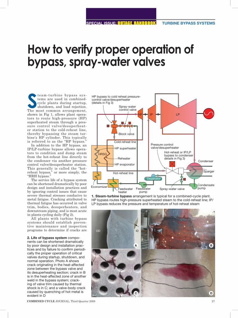
The most common arrangement, shown in Fig 1, allows plant opera-tors to route high-pressure (HP) superheated steam through a pres-sure control valve/desuperheat-er station to the cold-reheat line, thereby bypassing the steam tur-bine’s HP cylinder. This typically is referred to as the “HP bypass.”
In addition to the HP bypass, an IP/LP-turbine bypass allows opera-tors to condition and dump steam from the hot-reheat line directly to the condenser via another pressure control valve/desuperheater station. This generally is called the “hot-reheat bypass,” or more simply, the “HRH bypass.”
The service life of a bypass system can be shortened dramatically by poor design and installation practices and by ignoring control issues that cause severe thermal stresses conducive to metal fatigue. Cracking attributed to thermal fatigue has occurred in valve trim, bodies, desuperheaters, and downstream piping, and is most acute in plants cycling daily (Fig 2).
All plants with turbine bypass systems should establish preven-tive maintenance and inspection programs to determine if cracks are
How to verify proper operation of bypass, spray-water valves
Spray-water valveCondensatepump
HP bypass to cold reheat pressure-control valve/desuperheater (details in Fig 3)
HP IP LP
Spray-water control valve
Block valve
HP superheater
HRSG
HP evaporator
Economizer
Reheater
Cold-reheat line
Hot-reheat line
Feedwater heater
Feedwaterpump
Deaerator
Condenser
Sparger
Pressure control valve/desuperheater
Hot-reheat or IP/LP bypass to condenser details in Fig 3)
OD ID
A B
C D
2. Life of bypass system compo-nents can be shortened dramatically by poor design and installation prac-tices and by failure to confirm periodi-cally the proper operation of critical valves during startup, shutdown, and normal operation. Photo A shows crack originating in the heat-affected zone between the bypass valve and its desuperheating section; crack in B is in the heat-affected zone of another weld in the bypass system; crack-ing of valve trim caused by thermal shock is in C; and a valve-body crack caused by quenching of hot metal is evident in D
1. Steam-turbine bypass arrangement is typical for a combined-cycle plant. HP bypass routes high-pressure superheated steam to the cold-reheat line; IP/LP bypass reduces the pressure and temperature of hot-reheat steam
28 COMBINED CYCLE JOURNAL, Third Quarter 2008
SPECIAL ISSUE: OUTAGE HANDBOOKTURBINE BYPASS SYSTEMS
present or likely to develop. Normal measures of plant cyclic life—such as number of starts, duration of starts, number of trips, etc—are not adequate for gauging the condition of bypass systems. Rather, the fol-
lowing must be inspected, reviewed, and evaluated periodically to obtain a true assessment of condition:n Temperature gradients in the
bypass system.n Adjacent pipes and butt welds. n Steam valves, spray valves, desu-
perheaters, and dump devices.n Desuperheater control
logic, and startup and shutdown data from the plant historian.Perhaps the last thing
a roving operator wants to see on rounds is steam (or water) leaking out from the insulation at a bypass sta-tion. No way to tell at first sight if a catastrophic event is about to occur.
Most plants have pro-grams in place for periodic inspection of bypass sys-tems, as outlined by Steve Freitas of CCI-Control Com-ponents Inc, Rancho Santa Margarita, Calif, in the 2008 Outage Handbook (access www.combinedcyclejour-nal.com/archives.html, click 3Q/2007, click “Key elements of successful PM programs for turbine bypass systems” on cover.
But relatively few combined-cycle facilities run sophisticated diag-nostics on their bypass stations to ensure they are operating as design-ers intended and to verify that the designers’ intentions are correct for how plants must operate today (for example, cycling rather than base-load as designed).
Planning forensicsThe case history that follows chroni-cles work undertaken by personnel at InterGen’s La Rosita Power Project, Mexicali, Mexico (sidebar), and CCI engineers to determine the root cause of cracks discovered in the HRH and HP bypass systems for one of the plant’s three gas turbine/heat-recov-ery steam generator trains (so-called Unit C). Details were provided by La Rosita’s J Andres Felix, associate plant engineer, and CCI’s Dan Wat-son, development engineer.
Many plant-operations experts recommend that the type of diag-nostic study conducted at La Rosita be done during the commissioning of every plant and repeated about six months before each hot-gas-path or major inspection—depending on service duty—to ensure needed parts are available for the outage.
Felix said La Rosita contacted CCI well in advance of an upcoming major inspection/overhaul and that the vendor recommended the study profiled here. Reasoning was simple: Knowing the root cause of the crack-ing, the plant could implement cor-rective during the outage. La Ros-ita runs base-load in summer and cycles (usually daily) during most other months. It had operated about 40,000 equivalent hours by the time
this study was conducted in March 2008.
Review of information gathered during annual inspections and sent to CCI for the development of a meaningful proposal revealed the following per-tinent details about Unit C:n HRH bypass. A crack was discovered a few inches downstream of the first weld after the spray nozzles (Fig 3). The crack extended completely around the P22 (2¼ chrome) pipe, but only extended through the pipe wall at the 6 o’clock posi-tion, as evidenced by a water drip. Bulging of the pipe at that position was noted by engineers.n HP bypass. Cracks invis-ible to the naked eye were
found on the (1) pressure-control valve’s body drain pipe after the first elbow, (2) first weld down-stream of the spray nozzles, (3) on the weld connecting the bypass pipe to the cold-reheat header (P22 to P91 joint). Note that P91 is 9% chrome/1% molybdenum. It took about a day for CCI engi-
neers to instrument both bypass sta-
HOT-REHEAT BYPASS VALVE/DESUPERHEATER
HP-TURBINE BYPASS VALVE/DESUPERHEATER
~10 ft
~10 ft
TC1
TC2
TC3
TC4
TC5
TC6
TC7
TC8
TC9
Cross section 1 Cross section 2 Cross section 3
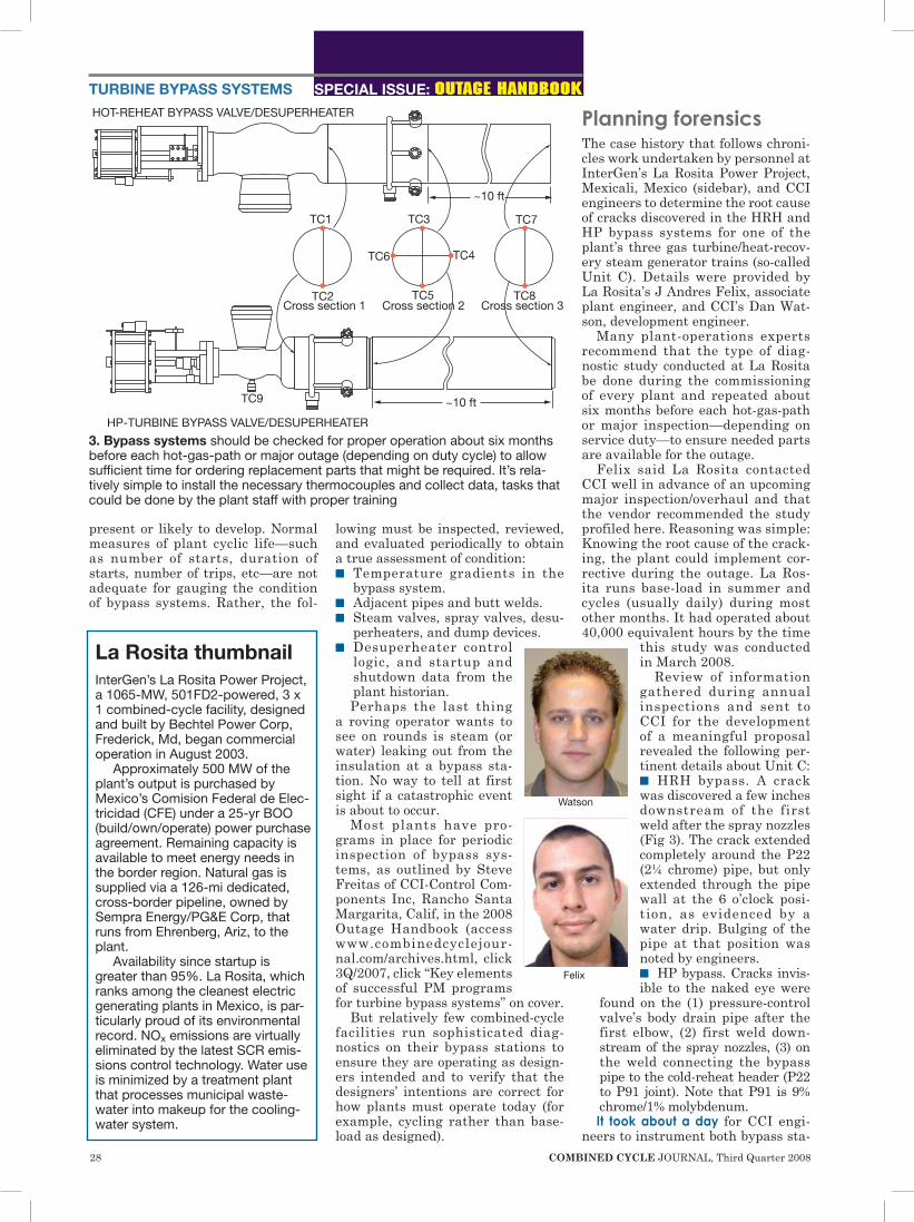
3. Bypass systems should be checked for proper operation about six months before each hot-gas-path or major outage (depending on duty cycle) to allow sufficient time for ordering replacement parts that might be required. It’s rela-tively simple to install the necessary thermocouples and collect data, tasks that could be done by the plant staff with proper training
Watson
Felix
La Rosita thumbnail InterGen’s La Rosita Power Project, a 1065-MW, 501FD2-powered, 3 x 1 combined-cycle facility, designed and built by Bechtel Power Corp, Frederick, Md, began commercial operation in August 2003.
Approximately 500 MW of the plant’s output is purchased by Mexico’s Comision Federal de Elec-tricidad (CFE) under a 25-yr BOO (build/own/operate) power purchase agreement. Remaining capacity is available to meet energy needs in the border region. Natural gas is supplied via a 126-mi dedicated, cross-border pipeline, owned by Sempra Energy/PG&E Corp, that runs from Ehrenberg, Ariz, to the plant.
Availability since startup is greater than 95%. La Rosita, which ranks among the cleanest electric generating plants in Mexico, is par-ticularly proud of its environmental record. NOx emissions are virtually eliminated by the latest SCR emis-sions control technology. Water use is minimized by a treatment plant that processes municipal waste-water into makeup for the cooling-water system.
Y&F fuel control valves, isolation valves, inlet guide vane actuators,and other accessories control an install base of over 10,000 turbines.
Our Global Sales and Service Network deliversengineered fuel control solutions
for industrial gas turbinesworldwide.
Whether it’s liquid,natural gas, Naphtha,or IGCC Syngas,we can meet your needs.
LiquidBypass
Valve
IGVSevereService
Actuator
CombinedValve
NaturalGas Valve
IGCC Valves
Naphtha Dump Valve
EMA Controller
LiquidFuel Splitter
PID with Dual LVDT Conditioner
Isolation Valve
EMAGas Control
1”, 2”, 3”
ELEC
TRIC
HYD
RA
ULI
C
www.yf.com • Tel. 315.457.3110 • [email protected]
A Leader in Electrically and HydraulicallyActuated Combustion Turbine Fuel Controls.
30 COMBINED CYCLE JOURNAL, Third Quarter 2008
SPECIAL ISSUE: OUTAGE HANDBOOKTURBINE BYPASS SYSTEMS
tions for diagnostic evaluation. Fig 3 shows this includes installation of eight Type K thermocouples (TCs) on both pressure control valves, plus another on the body of the HP bypass valve. Transducers also were installed on both the HRH and HP bypass and spray-water-control valves to accurately measure valve position.
The diagram shows where the TCs were located to detect temperature patterns indicative of abnormal or improper valve and/or desuperheater behavior. The transducers help iden-tify errors between the valve demand signals transmitted by the plant control system (DCS) and the actual positions of the valves.
Data were recorded continuously over two-day periods by CCI engineers on both the HRH and HP bypass sys-tems. The plan was to capture data from two startups and two shutdowns of the gas and steam turbines. While this goal was achieved for Unit C, the steam turbine was in continuous operation during the test period.
The analysis that follows focuses on the startups. During shutdowns, the HRH and HP bypasses did not operate, or opened only a small amount for a very brief period. How-ever, the primary goal, to identify the root cause of cracking, was achieved. Finally, engineers noticed some unusual behavior of the HP bypass system during normal plant opera-tion, as well as during startup, and that is covered as well.
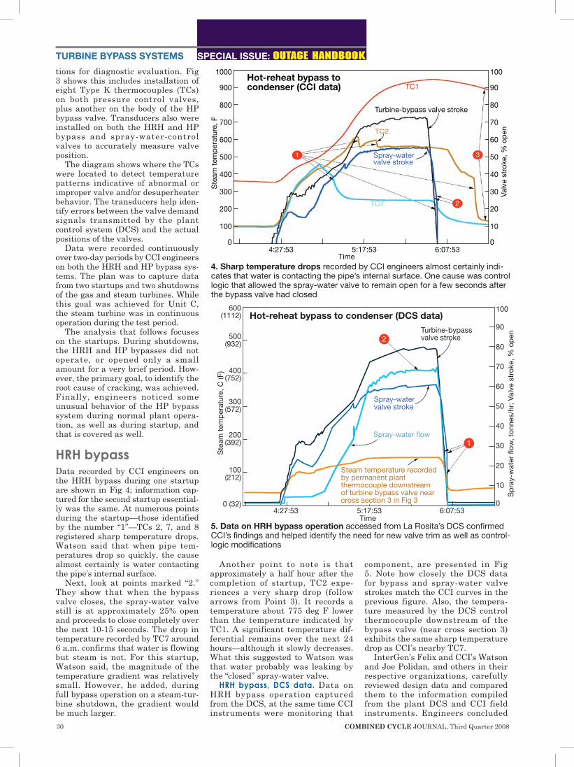
HRH bypassData recorded by CCI engineers on the HRH bypass during one startup are shown in Fig 4; information cap-tured for the second startup essential-ly was the same. At numerous points during the startup—those identified by the number “1”—TCs 2, 7, and 8 registered sharp temperature drops. Watson said that when pipe tem-peratures drop so quickly, the cause almost certainly is water contacting the pipe’s internal surface.
Next, look at points marked “2.” They show that when the bypass valve closes, the spray-water valve still is at approximately 25% open and proceeds to close completely over the next 10-15 seconds. The drop in temperature recorded by TC7 around 6 a.m. confirms that water is flowing but steam is not. For this startup, Watson said, the magnitude of the temperature gradient was relatively small. However, he added, during full bypass operation on a steam-tur-bine shutdown, the gradient would be much larger.
Another point to note is that approximately a half hour after the completion of startup, TC2 expe-riences a very sharp drop (follow arrows from Point 3). It records a temperature about 775 deg F lower than the temperature indicated by TC1. A significant temperature dif-ferential remains over the next 24 hours—although it slowly decreases. What this suggested to Watson was that water probably was leaking by the “closed” spray-water valve.
HRH bypass, DCS data. Data on HRH bypass operation captured from the DCS, at the same time CCI instruments were monitoring that
component, are presented in Fig 5. Note how closely the DCS data for bypass and spray-water valve strokes match the CCI curves in the previous figure. Also, the tempera-ture measured by the DCS control thermocouple downstream of the bypass valve (near cross section 3) exhibits the same sharp temperature drop as CCI’s nearby TC7.
InterGen’s Felix and CCI’s Watson and Joe Polidan, and others in their respective organizations, carefully reviewed design data and compared them to the information compiled from the plant DCS and CCI field instruments. Engineers concluded
Ste
am t
emp
erat
ure,
F
1000
900
800
700
600
500
400
300
200
100
0
100
90
80
70
60
50
40
30
20
10
0
Time4:27:53 5:17:53 6:07:53
Valv
e st
roke
, % o
pen
Hot-reheat bypass to condenser (CCI data)
1
2
3
TC1
Turbine-bypass valve stroke
TC2
Spray-watervalve stroke
TC7
4. Sharp temperature drops recorded by CCI engineers almost certainly indi-cates that water is contacting the pipe’s internal surface. One cause was control logic that allowed the spray-water valve to remain open for a few seconds after the bypass valve had closed
Ste
am t
emp
erat
ure,
C (F
)
600 (1112)
500 (932)
400 (752)
300 (572)
200 (392)
100 (212)
0 (32)
100
90
80
70
60
50
40
30
20
10
04:27:53 5:17:53 6:07:53
Time S
pra
y-w
ater
flow
, ton
nes/
hr; V
alve
str
oke,
% o
pen
Hot-reheat bypass to condenser (DCS data)Turbine-bypass valve stroke
Spray-water valve stroke
Spray-water flow
Steam temperature recorded by permanent plant thermocouple downstream of turbine bypass valve near cross section 3 in Fig 3
2
1
5. Data on HRH bypass operation accessed from La Rosita’s DCS confirmed CCI’s findings and helped identify the need for new valve trim as well as control-logic modifications

32 COMBINED CYCLE JOURNAL, Third Quarter 2008
SPECIAL ISSUE: OUTAGE HANDBOOKTURBINE BYPASS SYSTEMS
that approximately 20% more spray water was being injected into the steam flow than was indicated by designers’ calculations.
Startup data from the technical specifications indicated a fully open bypass valve handling a steam flow of 219 tonnes (T, a metric ton or 2205 lb)/hr and a matching spray-water requirement of 72.4 T/hr. Test data captured during the carefully moni-tored start last spring showed the bypass valve was never more than 80% open. All other operating condi-tions either matched, or were very close to, those calculated by design-ers.
When the bypass valve is at 80% stroke, spray-water requirement should be 57.9 T/hr, or 80% of the
72.4-T/hr design value. DCS data show that the actual flow rate was about 69 T/hr—nearly 20% more than it should have been. The differ-ence could be caused by instrumenta-tion error or an error in control.
Engineers concluded that the HRH bypass system had the following four major problems, presented in the order of their severity:
1. Spray-water valve was leak-ing, allowing water to flow into the bypass piping. Evidence: The sharp temperature drop recorded by TC2 (Fig 4) about a half hour after startup was completed. The continual flow of water cooled the bottom of the pipe to near spray-water temperature while the top of the pipe at the same cross section (Fig 3) was 775 deg F hotter.
A temperature gradient of this mag-nitude creates enormous stresses on the pipe and may be the primary rea-son that the pipe cracked. Recommendation. Replace the plug, seat, and trim in the spray-water valve to eliminate the leak.
This work was done.2. Poor synchronization of the
bypass and spray-water valves dur-ing closing. As mentioned earlier, the spray-water valve closed about 15 seconds after the bypass valve closed. Never allow water to enter the bypass system when there is no steam flow. This is one of the primary causes of pipe quenching.
During the La Rosita startups ana-lyzed by plant and CCI engineers, the thermal gradients measured on the pipe wall were relatively small (not shown on the diagrams to reduce clutter). But the effects on the bypass-valve outlet diffuser were almost certainly more severe. Also, bypass operation during a steam-turbine shutdown would likely cause even more severe tempera-ture quenching of the outlet piping and the valve’s outlet diffuser. Such sharp reductions in temperature cre-ate additional piping stress and are conducive to cracking, especially dur-ing cyclic operation. Recommendations. (A) Change con-trol logic to ensure that the spray-water valve opens after—and closes before—the bypass valve, so there never is spray-water flow without steam flow. (B) Modify control logic to inject the proper amount of spray water during startups. (C) Review DCS data for other operating cases to verify accuracy of spray-water flow.
Felix said the service firm La Ros-ita uses for its control-systems work was assigned the task of trouble-shooting spray-water valve control logic. One issue identified was with the enthalpy-calculational routine and the equation governing that was corrected. Also, the interlock that prevents spray water from entering the bypass system when steam flow ceases was adjusted simply by tweak-ing the 4-20-mA signal setting that controls the opening and closing of the spray valve.
Tests conducted by the plant fol-lowing these adjustments confirmed proper valve operation because no delta T was observed.
3. Too much spray water was injected for the given startup steam flow. This was corrected with chang-es to the control logic described in the previous item.
4. Sharp temperature drops dur-ing startup are evident from the TC2 data shown in Fig 4. Engineers were
HP-turbine bypass to cold-reheat line (CCI data)
Ste
am t
emp
erat
ure,
F
1000
900
800
700
600
500
400
300
200
100
0
100
90
80
70
60
50
40
30
20
10
0
Valv
e st
roke
, % o
pen
4:53:14 5:59:54 7:06:34Time
TC2
TC6
TC4
TC5
Turbine-bypassvalve stroke
Spray-watervalve stroke
TC7
2
1
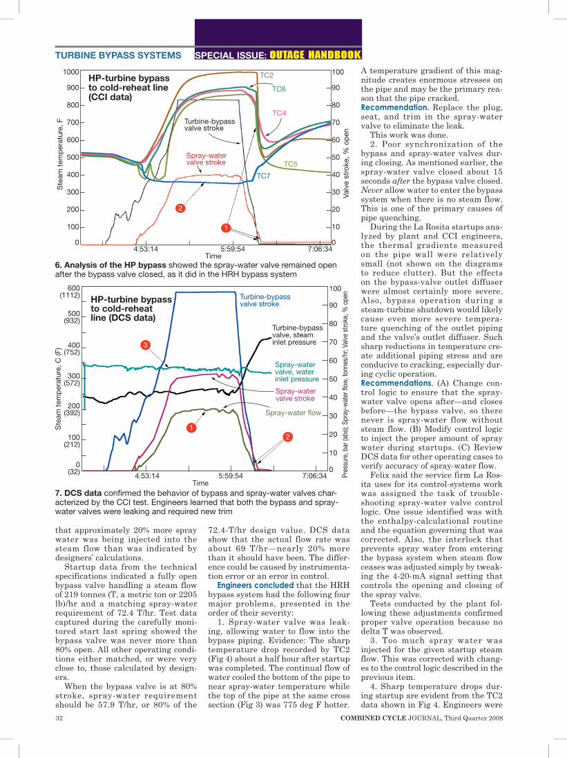
6. Analysis of the HP bypass showed the spray-water valve remained open after the bypass valve closed, as it did in the HRH bypass system
600 (1112)
500 (932)
400 (752)
300 (572)
200 (392)
100 (212)
0 (32)
Ste
am t
emp
erat
ure,
C (F
)
100
90
80
70
60
50
40
30
20
10
0
Pres
sure
, bar
(abs
); Sp
ray-
wat
er fl
ow, t
onne
s/hr
; Val
ve s
troke
, % o
pen
HP-turbine bypass to cold-reheat line (DCS data)
Turbine-bypass valve stroke
4:53:14 5:59:54 7:06:34 Time
Spray-water valve, water inlet pressure
Spray-water valve stroke
Spray-water flow
Turbine-bypass valve, steam inlet pressure
1
3
2
7. DCS data confirmed the behavior of bypass and spray-water valves char-acterized by the CCI test. Engineers learned that both the bypass and spray-water valves were leaking and required new trim

Answers for energy.
Getting more and more energy from fewer and fewer resources is our never-ending mission.In addition to excellent availability and utmost reliability, efficiency is a key requirement when it comes to supplying energy for the world’s steadily growing megacities. Basically, it’s all about making best use of all resources. We apply this principle across the entire energy conversion chain to take efficiency to totally new levels. Our new 800 kV transformer, for example, makes possible the efficient transmission of electric energy in the gigawatt range over distances of 1,000 kilometers and more. And our new generation of gas turbines makes combined cycle power plants deliver a record-breaking efficiency of more than 60 percent. www.siemens.com/energy
How can we get by with less when the whole world keeps asking for more?
CCJournal-January2009.indd 1 12/18/08 11:09:20 AM
34 COMBINED CYCLE JOURNAL, Third Quarter 2008
not sure while these occurred and no action was taken.
Other recommendations made by CCI included the following: (1) Inspect the inside of the pipe and the valve’s outlet diffuser for dam-age that my not be visible from the outside. (2) Service and inspect all spray nozzles. (3) Calibrate spray-water flow meters. Plant completed most of the work suggested and
scheduled the remainder for future outages.
HP bypassData recorded by CCI engineers on the HP bypass during one startup are shown in Fig 6; information captured for the second startup was similar. Lower two arrows originat-ing at Point 1 in the diagram show
that when the bypass valve closes, the spray-water valve is still open approximately 8% and proceeds to close over the next two minutes.
The negative temperature gradi-ent observed on the curves for TCs 2, 4, 5, and 6 at about 6:30 a.m. confirmed spray water was flowing when steam was not. As noted in the section on the HRH bypass, such a large gradient causes an enormous amount of pipe stress. It could even-tually lead to cracking if the root cause is not corrected—especially considering the unit’s daily-start/shutdown regimen.
Point 2 reveals that TC7 was at saturation temperature for the duration of the startup. This sug-gests that the pipe was either in constant contact with water or the steam at that location actually was at saturation temperature. Either way, too much spray water was being injected.
DCS data. Information on HP bypass operation captured from the DCS, at the same time CCI instru-ments were monitoring that compo-nent, are presented in Fig 7. Note that DCS data on the stroke of bypass and spray-water valves exhibit the same behavior as that identified by CCI in Fig 6.
Comparison of design and operat-ing data for the HP bypass, as was done for the HRH bypass, revealed
1000
900
800
700
600
500
400
300
200
100
0
Ste
am t
emp
erat
ure,
F
100
90
80
70
60
50
40
30
20
10
0
Valv
e st
roke
, % o
pen
HP-turbine bypass to cold-reheat line, “normal” plant operation (CCI data)
TC2TC2
TC4 TC4
TC5
Turbine-bypass valve stroke
Turbine-bypass valve stroke
Spray-water valve stroke
Day 1, 12:06:34 Day 1, 21:49:54 Day 2, 7:33:14Time
2
1
3
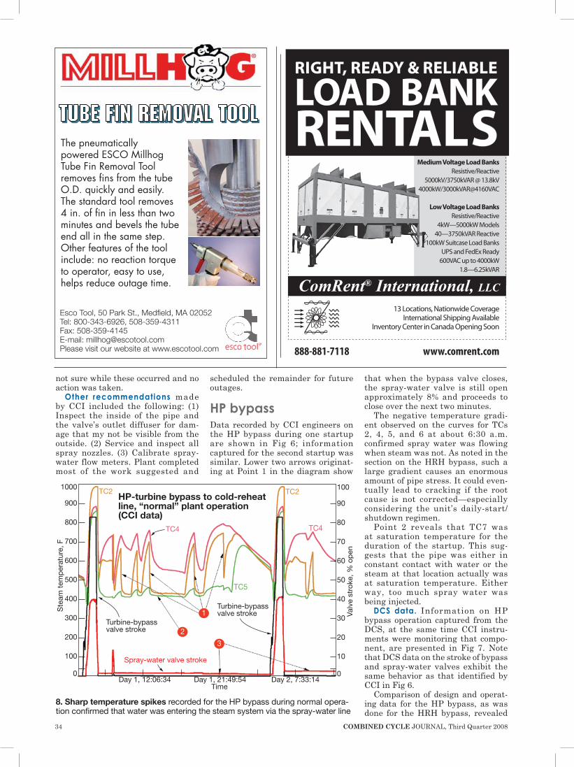
8. Sharp temperature spikes recorded for the HP bypass during normal opera-tion confirmed that water was entering the steam system via the spray-water line
888-881-7118
RIGHT, READY & RELIABLE
LOAD BANK RENTALS
www.comrent.com
13 Locations, Nationwide Coverage International Shipping Available
Inventory Center in Canada Opening Soon
Medium Voltage Load BanksResistive/Reactive
5000kV/3750kVAR @ 13.8kV4000kW/3000kVAR@4160VAC
Low Voltage Load BanksResistive/Reactive
4kW—5000kW Models40—3750kVAR Reactive
100kW Suitcase Load BanksUPS and FedEx Ready
600VAC up to 4000kW1.8—6.25kVAR
ComRent® International, LLC
The pneumatically powered ESCO Millhog Tube Fin Removal Tool removes fins from the tube O.D. quickly and easily. The standard tool removes 4 in. of fin in less than two minutes and bevels the tube end all in the same step. Other features of the tool include: no reaction torque to operator, easy to use, helps reduce outage time.
Esco Tool, 50 Park St., Medfield, MA 02052Tel: 800-343-6926, 508-359-4311Fax: 508-359-4145 E-mail: [email protected] visit our website at www.escotool.com

COMBINED CYCLE JOURNAL, Third Quarter 2008 35
that approximately 82% more spray water was being injected during startup than specified. Specifically, a wide-open bypass valve handles 166 T/hr of main steam and requires 18.8 T/hr of spray water. During the startup evaluated, the bypass valve reached a maximum stroke of 97% and should have been supplied 18.2 T/hr of spray water. But actual flow was 33.2 T/hr. As mentioned earlier, this could be caused by instrument or control error.
The spray-water inlet pressure during the startup observed was 55 bar (abs). According to the design specifications, the inlet pressure should have been 42.2 bar (abs) for all operating conditions. Thus the spray-valve inlet pressure was about 30% higher than specified.
Conclusions. Engineers concluded that the HP bypass system had the following three major problems, pre-sented in the order of their severity:
1. Poor synchronization of the bypass and spray-water valves dur-ing closing. During the startups evaluated, injection of spray water after steam flow had ceased resulted in the rapid reduction in pipe wall temperature as measured by TCs 2, 4, 5, and 6 in Fig 6. The 500-deg-F temperature drop experienced quali-fies as “thermal shock” and one of the main reasons for the cracks at the desuperheater outlet.
2. Bypass and spray-water valves were leaking.
3. Too much spray water was injected for the given startup steam flow.
Recommendations and action taken by the plant to correct the root causes of the HP bypass prob-lems experienced were the same as those for the HRH bypass described earlier, with one exception: Plug, seat, and trim were replaced for the bypass valve, in addition to the spray-water valve.
Normal plant operationHP bypass data also were recorded between the two startups ana-lyzed—that is, during normal plant operation. However, the TC curves in Fig 8 were not what engineers considered “normal,” exhibiting sharp temperature spikes while the unit was in service (region between the startup peaks for the first and second days at the left- and right-hand sides of the chart). During this time there was no movement of the bypass or spray-water valves.
From the detailed information col-lected during the first startup (Figs 6 and 7), engineers knew that the HP bypass valve was leaking and con-stantly passing steam to the down-stream piping. This would cause high-
er downstream temperatures, ones that should be relatively constant.
However, curves TC2 and TC4 reveal sharp drops in the down-stream temperature, as the arrows from Point 1 highlight. Only injec-tion of water could make this occur. Engineers concluded that either of the following was happening: The spray-water valve was slightly open and constantly passing water, or it was closed and leaking.
More evidence is provided by curve TC5, which remained at or very near saturation temperature and exhibit-ed only small temperature variations (Point 2). Data from TC3 (not shown to minimize graphics “clutter”), col-lected at the top of the same pipe cross section as TC5, was constantly 300 to 400 deg F higher than the TC5 readings, proving water was flowing along the bottom of the pipe.
Finally, position-feedback data from the spray-water valve indi-cated that it might have been from 2% to 4% open during operation (fol-low arrows from Point 3). But based on DCS data, engineers determined that the zero point for the spray-wa-ter valve’s position-feedback mea-surement may have been skewed by movement of the feedback trans-ducer. Conclusion: The spray-water valve actually was shut off during normal operation, reinforcing the belief that it was leaking. ccj
PHONE: 323.832.8316 www.GasTurbineInletAirFilters.com
Produce More Power Protect Your BladesReduce Heat Rate Reduce Water Washes
Related Documents