Steam Sterilization Cycle Modeling and Optimization for T EAM M EMBERS Jared Humphreys Mike Arena Matt Lototski John Chaplin Colin Bradley A DVISOR Greg Kowalski S PONSOR - M ICROFLUIDICS Mimi Panagiotou Dan Dalessio

Steam Sterilization Cycle Modeling and Optimization for T EAM M EMBERS Jared Humphreys Mike Arena Matt Lototski John Chaplin Colin Bradley A DVISOR Greg.
Dec 16, 2015
Welcome message from author
This document is posted to help you gain knowledge. Please leave a comment to let me know what you think about it! Share it to your friends and learn new things together.
Transcript

Steam Sterilization Cycle Modeling and Optimization for
TEAM MEMBERSJared Humphreys
Mike ArenaMatt LototskiJohn ChaplinColin Bradley
ADVISORGreg
Kowalski
SPONSOR - MICROFLUIDICSMimi Panagiotou
Dan Dalessio

Background
● Manufacture machines called “Microfluidizers”
● These machines force product through fixed geometry micro-channels using intense pressure
● Product goes in as random large particles and exits as uniformly sized nanoparticles

Background● Used in a growing number of pharmaceutical,
personal care, biotechnology, food and chemical applications
● System must be sterilized between each processing session to ensure purity of product
● Sterilization cycle is multi-staged and time consuming
● Wetted surface must be exposed to steam at 121°C for at least 20 minutes per ASME BPE-a-2004 requirements
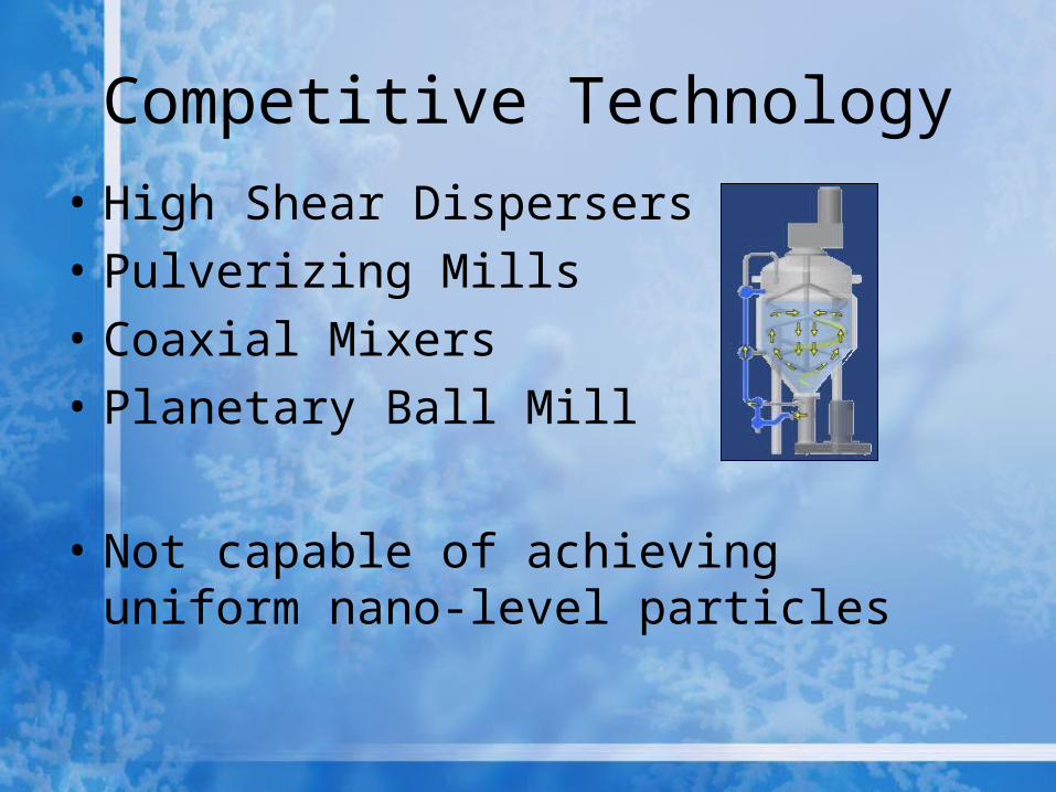
Competitive Technology• High Shear Dispersers• Pulverizing Mills• Coaxial Mixers• Planetary Ball Mill
• Not capable of achieving uniform nano-level particles

Project Goals• To verify that all
sections of the system which come in contact with the product are heated to 121°C or higher for at least 20 minutes during the steam sterilization cycle
• Find a solution to stop the intensifier pump seal failure
Product Chamber
Piston
Failing Seal
FAILING SEAL WITHIN INTENSIFIER PUMPS
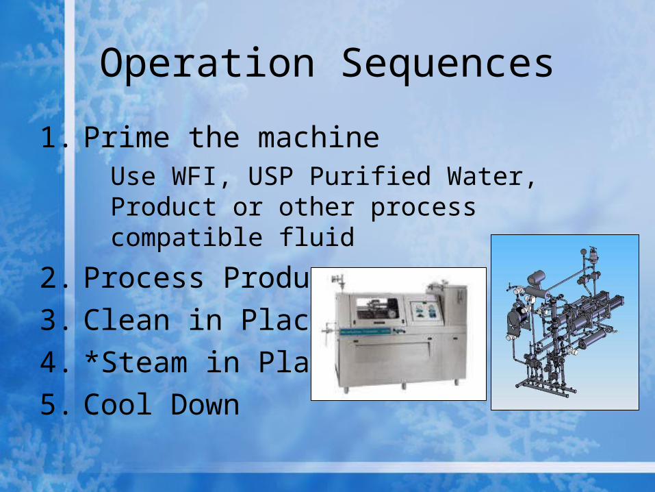
Operation Sequences
1. Prime the machineUse WFI, USP Purified Water, Product or other process compatible fluid
2. Process Product3. Clean in Place4. *Steam in Place* 5. Cool Down

Steam in Place Process
● Steam in Place – 3 Stages● Heat product wetted piping and outside
of chambers first● Saturated steam from boiler at 138° C
and 35 psig is passed through the system
● Temperature and pressure are monitored at the system inlet and outlet

Intensifier Pump Process
Piston
Check Valve #1
Check Valve #2
Seal
To Chambers
Step 1
Step 2

Seal Failure
• Seal failure method “thermal degradation”
• Seal material: TIVAR H.O.T.• Maximum seal operating
temperature: 135°C• Excessive temperature exposure or
thermal cycling causes the seal to crack and become softer

Deliverables
● Computer simulation of steam in using computational fluid dynamics software (Fluent)
● Analysis of simulation to determine that current process complies with ASME sterilization requirements
● Recommendations of changes to current process to eliminate seal failure

Solidworks Model
● Extremely complex● Incompatible with
Fluent analysis as-is● Many components
needed to be remodeled with interior flow path defined (heat exchangers, pumps, valves)

Area of Concern
• Focus area of current system successfully modeled in Solidworks
• File imported to Gambit for 3D meshing and subsequent Fluent Analysis
• Determined temperature around the seals to aid design solutions
Temperature and Pressure Sensors
Intensifier Pumps
Chambers

Pressure Outlet Calculations
P1-P2 = (64*μ*V*L)/(2*D2) P1-0 = [(64)*(0.000013 Ns/m2)*(7.4 m/s)*(.3
m)]/[(2)*(0.000078m)2]P1 = 151,794 Pa
P1 = inlet pressureP2 = outlet pressureμ = viscosityV = velocityD = DiameterL = length of chambers
P1*V1=P2*V2
(35psig)(1.1in^2)=P2(13.81in^2)
P2 = 2.95 psi Draw Pressure
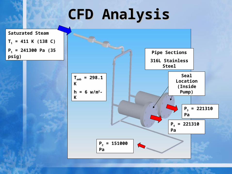
Saturated Steam
T1 = 411 K (138 C)
P1 = 241300 Pa (35 psig)
Tamb = 298.1 K
h = 6 w/m2-K
P2 = 151000 Pa
Pipe Sections
316L Stainless Steel
CFD AnalysisCFD Analysis
P4 = 221310 Pa
P3 = 221310 Pa
Seal Location (Inside Pump)

GAMBIT MeshGAMBIT Mesh

Static Pressure (Pa)Static Pressure (Pa)
P2 = 151000 Pa
P4 = 221310 Pa
P3 = 221310 Pa
P1 = 241300 Pa

Static Temperature (K)Static Temperature (K)
Seal Temperatures ~408 K (135’ C)

Velocity (m/s)Velocity (m/s)

Reynolds NumberReynolds Number
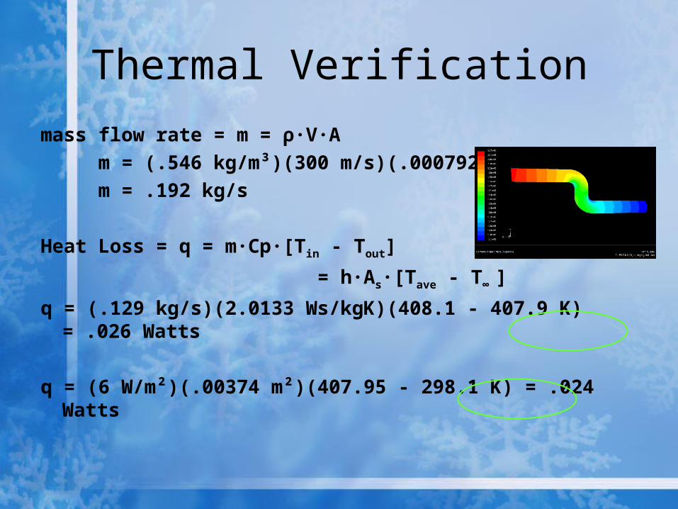
Thermal Verification
mass flow rate = m = ρ·V·A m = (.546 kg/m³)(300 m/s)(.000792 m²) m = .192 kg/s
Heat Loss = q = m·Cp·[Tin - Tout]
= h·As·[Tave - T∞ ]
q = (.129 kg/s)(2.0133 Ws/kgK)(408.1 - 407.9 K) = .026 Watts
q = (6 W/m²)(.00374 m²)(407.95 - 298.1 K) = .024 Watts

Proposed Solution
• By decreasing inlet temperature 5°, seal temperatures are well below limits (130° C max)
• Transient analysis shows inlet temperature adjustment does not significantly affect warm-up time
• Does not require any modification to current system design

Static Temperature (K)Static Temperature (K)
Decreased Inlet Temp 406 K (133°C)
Seal Temperatures
~403 K (130°C)
Future Work
• Remodel pump chambers in GAMBIT to enable analysis with piston motion simulated
• Model remaining steam phases to ensure reduced steam temperature can be used throughout entire sterilization process

Questions?
Related Documents