Steam Power Plants Components Lecture 4 Dr: Aly Hassan Elbatran

Welcome message from author
This document is posted to help you gain knowledge. Please leave a comment to let me know what you think about it! Share it to your friends and learn new things together.
Transcript
Steam Power Plants Components Lecture 4Dr: Aly Hassan Elbatran
2
Steam Power Plant Components Steam Generator components

3
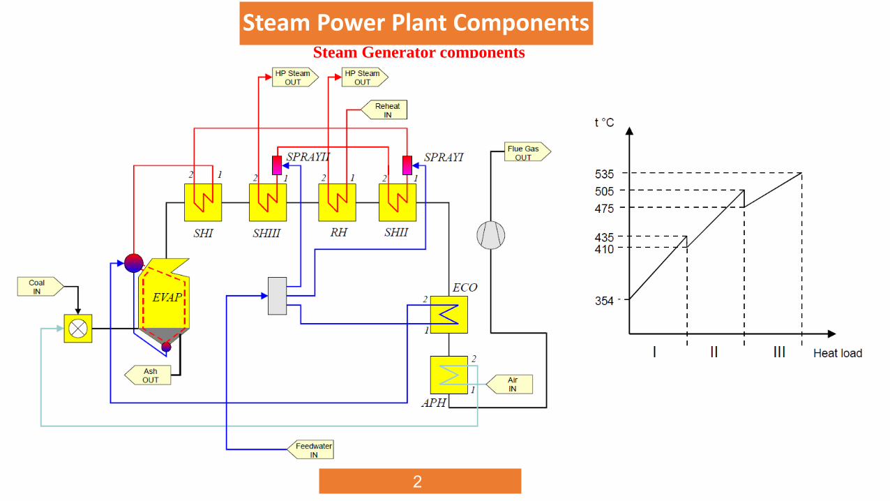
Steam Power Plant Components
Steam Generator components
T-s diagram representing the heat surfaces in a boiler

4
Steam Power Plant Components
Steam Generator components
T-Q diagram representing the heat surfaces in a boiler
5
Steam Power Plant Components
Steam Generator components
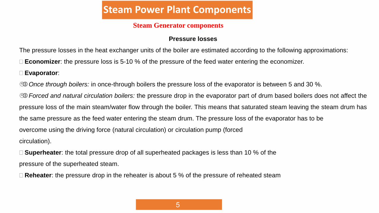
Pressure losses
The pressure losses in the heat exchanger units of the boiler are estimated according to the following approximations:
Economizer: the pressure loss is 5-10 % of the pressure of the feed water entering the economizer.
Evaporator:
Once through boilers: in once-through boilers the pressure loss of the evaporator is between 5 and 30 %.
Forced and natural circulation boilers: the pressure drop in the evaporator part of drum based boilers does not affect the
pressure loss of the main steam/water flow through the boiler. This means that saturated steam leaving the steam drum has
the same pressure as the feed water entering the steam drum. The pressure loss of the evaporator has to be
overcome using the driving force (natural circulation) or circulation pump (forced
circulation).
Superheater: the total pressure drop of all superheated packages is less than 10 % of the
pressure of the superheated steam.
Reheater: the pressure drop in the reheater is about 5 % of the pressure of reheated steam

6
Boiler Performance Definitions

7
Boiler Performance Definitions
8
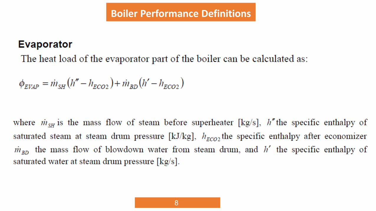
Boiler Performance Definitions

9
Boiler Performance Definitions
10
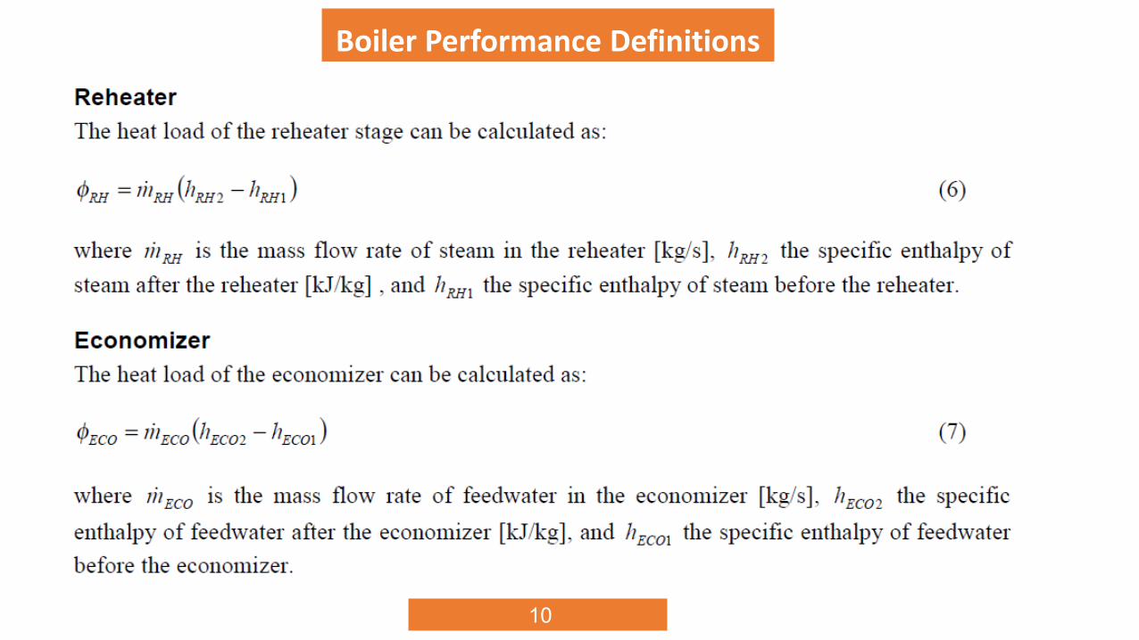
Boiler Performance Definitions
11
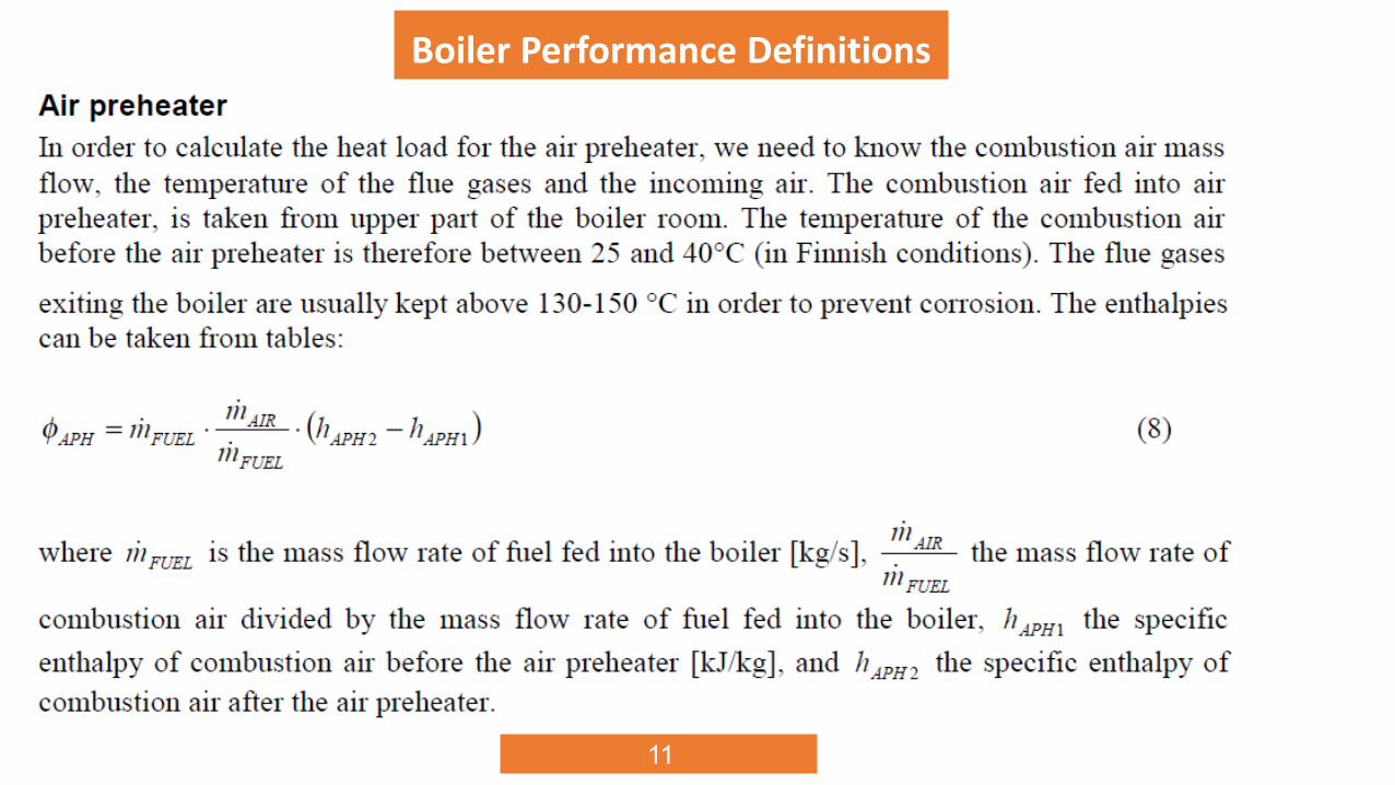
Boiler Performance Definitions

1)A steam generator generates 500 tons/hr of steam at 150 bars and 500oC
from water at 180oC. The steam generator consists of boiler, S/H,
economizer and air preheater. The C.V. of the fuel used is 42 MJ/Kg, the
boiler efficiency is 80% and A/F is 19/1. The temperature of flue gases inlet
to boiler chimney is 200oC and the temperature of water leaving the
economizer is 270oC. The temperatures of air inlet and outlet from A/H are
20oC and 150oC respectively calculate.
The fuel consumption.
The flue gas temperature at inlet to economizer.
The flue gas temperature at inlet to S/H
Related Documents