Steam Turbine Introduction A steam turbine converts the energy of high-pressure, high temperature steam produced by a steam generator into shaft work. The energy conversion is brought about in the following ways: 1. The high-pressure, high-temperature steam first expands in the nozzles emanates as a high velocity fluid stream. 2. The high velocity steam coming out of the nozzles impinges on the blades mounted on a wheel. The fluid stream suffers a loss of momentum while flowing past the blades that is absorbed by the rotating wheel entailing production of torque. 3. The moving blades move as a result of the impulse of steam (caused by the change of momentum) and also as a result of expansion and acceleration of the steam relative to them. In other words they also act as the nozzles. A steam turbine is basically an assembly of nozzles fixed to a stationary casing and rotating blades mounted on the wheels attached on a shaft in a row-wise manner. In 1878, a Swedish engineer, Carl G. P. de Laval developed a simple impulse turbine, using a convergent-divergent (supersonic) nozzle which ran the turbine to a maximum speed of 100,000 rpm. In 1897 he constructed a velocity-compounded impulse turbine (a two-row axial turbine with a row of guide vane stators between them. Auguste Rateau in France started experiments with a de Laval turbine in 1894, and developed the pressure compounded impulse turbine in the year 1900. In the USA , Charles G. Curtis patented the velocity compounded de Lavel turbine in 1896 and transferred his rights to General Electric in 1901. In England , Charles A. Parsons developed a multi-stage axial flow reaction turbine in 1884. Steam turbines are employed as the prime movers together with the electric generators in thermal and nuclear power plants to produce electricity. They are also used to propel large ships, ocean liners, submarines and to drive power absorbing machines like large compressors, blowers, fans and pumps. Turbines can be condensing or non-condensing types depending on whether the back pressure is below or equal to the atmosphere pressure. Flow Through Nozzles A nozzle is a duct that increases the velocity of the flowing fluid at the expense of pressure drop. A duct which decreases the velocity of a fluid and causes a corresponding increase in pressure is a diffuser . The same duct may be either a nozzle or a diffuser

Welcome message from author
This document is posted to help you gain knowledge. Please leave a comment to let me know what you think about it! Share it to your friends and learn new things together.
Transcript
Steam Turbine
Introduction
A steam turbine converts the energy of high-pressure, high temperature steam produced
by a steam generator into shaft work. The energy conversion is brought about in the
following ways:
1. The high-pressure, high-temperature steam first expands in the nozzles emanates
as a high velocity fluid stream.
2. The high velocity steam coming out of the nozzles impinges on the blades
mounted on a wheel. The fluid stream suffers a loss of momentum while flowing
past the blades that is absorbed by the rotating wheel entailing production of
torque.
3. The moving blades move as a result of the impulse of steam (caused by the
change of momentum) and also as a result of expansion and acceleration of the
steam relative to them. In other words they also act as the nozzles.
A steam turbine is basically an assembly of nozzles fixed to a stationary casing and
rotating blades mounted on the wheels attached on a shaft in a row-wise manner. In 1878,
a Swedish engineer, Carl G. P. de Laval developed a simple impulse turbine, using a
convergent-divergent (supersonic) nozzle which ran the turbine to a maximum speed of
100,000 rpm. In 1897 he constructed a velocity-compounded impulse turbine (a two-row
axial turbine with a row of guide vane stators between them.
Auguste Rateau in France started experiments with a de Laval turbine in 1894, and
developed the pressure compounded impulse turbine in the year 1900.
In the USA , Charles G. Curtis patented the velocity compounded de Lavel turbine in
1896 and transferred his rights to General Electric in 1901.
In England , Charles A. Parsons developed a multi-stage axial flow reaction turbine in
1884.
Steam turbines are employed as the prime movers together with the electric generators in
thermal and nuclear power plants to produce electricity. They are also used to propel
large ships, ocean liners, submarines and to drive power absorbing machines like large
compressors, blowers, fans and pumps.
Turbines can be condensing or non-condensing types depending on whether the back
pressure is below or equal to the atmosphere pressure.
Flow Through Nozzles
A nozzle is a duct that increases the velocity of the flowing fluid at the expense of
pressure drop. A duct which decreases the velocity of a fluid and causes a corresponding
increase in pressure is a diffuser . The same duct may be either a nozzle or a diffuser

depending upon the end conditions across it. If the cross-section of a duct decreases
gradually from inlet to exit, the duct is said to be convergent. Conversely if the cross
section increases gradually from the inlet to exit, the duct is said to be divergent. If the
cross-section initially decreases and then increases, the duct is called a convergent-
divergent nozzle. The minimum cross-section of such ducts is known as throat. A fluid is
said to be compressible if its density changes with the change in pressure brought about
by the flow. If the density does not changes or changes very little, the fluid is said to be
incompressible. Usually the gases and vapors are compressible, whereas liquids are
incompressible .
Nozzle, Steam Nozzle and Steam Turbine
STAGNATION, SONIC PROPERTIES AND ISENTROPIC EXPANSION IN NOZZLE
The stagnation values are useful reference conditions in a compressible flow. Suppose the
properties of a flow (such as T, p, ρ etc.) are known at a point. The stagnation properties
at a point are defined as those which are to be obtained if the local flow were imagined to
cease to zero velocity isentropically. The stagnation values are denoted by a subscript
zero. Thus, the stagnation enthalpy is defined as
For a calorically perfect gas, this yields,
(18.1)
which defines the stagnation temperature. It is meaningful to express the ratio of
in the form
or, (18.2)
If we know the local temperature (T) and Mach number (Ma), we can fine out the
stagnation temperature . Consequently, isentropic relations can be used to obtain
stagnation pressure and stagnation density as.
(18.3)
(18.4)
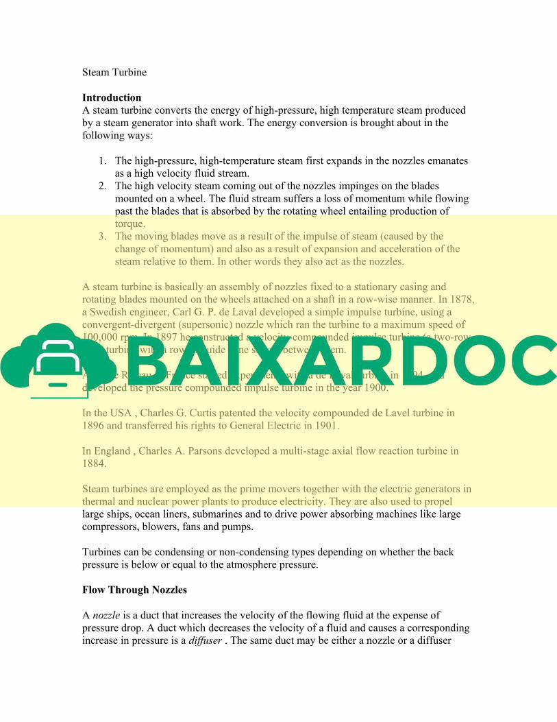
In general, the stagnation properties can vary throughout the flow field.
However, if the flow is adiabatic, then is constant throughout the flow. It follows
that the and are constant throughout an adiabatic flow, even in the presence of
friction. Here a is the speed of sound and the suffix signifies the stagnation condition. It is
understood that all stagnation properties are constant along an isentropic flow. If such a
flow starts from a large reservoir where the fluid is practically at rest, then the properties
in the reservoir are equal to the stagnation properties everywhere in the flow (Fig. 18.1).
Fig 18.1 An isentropic process starting from a reservoir
There is another set of conditions of comparable usefulness where the flow is sonic,
Ma=1.0. These sonic, or critical properties are denoted by asterisks: and. .
These properties are attained if the local fluid is imagined to expand or compress
isentropically until it reachers Ma=1.
We have already discussed that the total enthalpy, hence , is conserved so long the
process is adiabatic, irrespective of frictional effects. In contrast, the stagnation pressure
and density decrease if there is friction.
From Eq.(18.1), we note that
or, (18.5a)
is the relationship between the fluid velocity and local temperature (T), in an adiabatic
flow. The flow can attain a maximum velocity of
(18.5b)
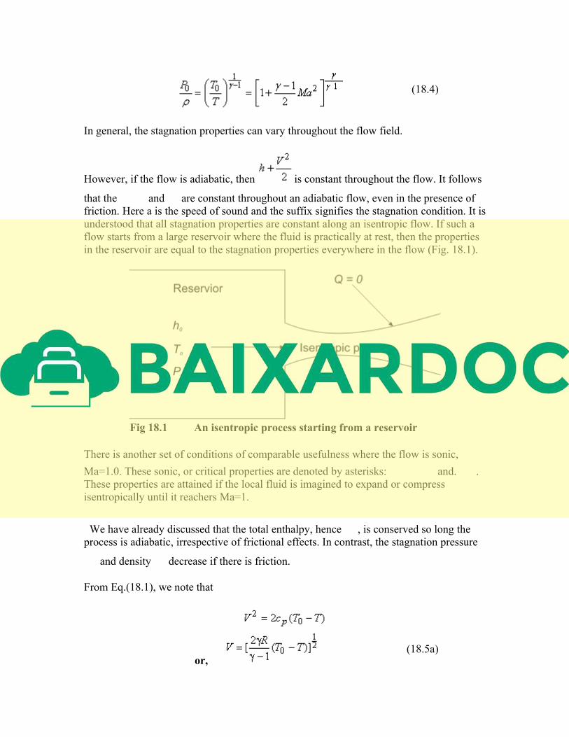
As it has already been stated, the unity Mach number, Ma=1, condition is of special
significance in compressible flow, and we can now write from Eq.(18.2), (18.3) and
(18.4).
(18.6a)
(18.6b)
(18.6c)
For diatomic gases, like air , the numerical values are
The fluid velocity and acoustic speed are equal at sonic condition and is
(18.7a)
or,
( 18.7b )
We shall employ both stagnation conditions and critical conditions as reference
conditions in a variety of one dimensional compressible flows.
Effect of Area Variation on Flow Properties in Isentropic Flow
In considering the effect of area variation on flow properties in isentropic flow, we shall
concern ourselves primarily with the velocity and pressure. We shall determine the effect
of change in area, A, on the velocity V, and the pressure p.
From Bernoulli's equation, we can write
or,
Dividing by , we obtain
(19.1)
A convenient differential form of the continuity equation can be obtained from Eq.
(14.50) as
Substituting from Eq. (19.1),
or, (19.2)
Invoking the relation ( ) for isentropic process in Eq. (19.2), we get
(19.3)
From Eq. (19.3), we see that for Ma<1 an area change causes a pressure change of the
same sign, i.e. positive dA means positive dp for Ma<1. For Ma>1, an area change causes
a pressure change of opposite sign.
Again, substituting from Eq.(19.1) into Eq. (19.3), we obtain
(19.4)
From Eq. (19.4), we see that Ma<1 an area change causes a velocity change of opposite
sign, i.e. positive dA means negative dV for Ma<1. For Ma>1, an area change causes a
velocity change of same sign.
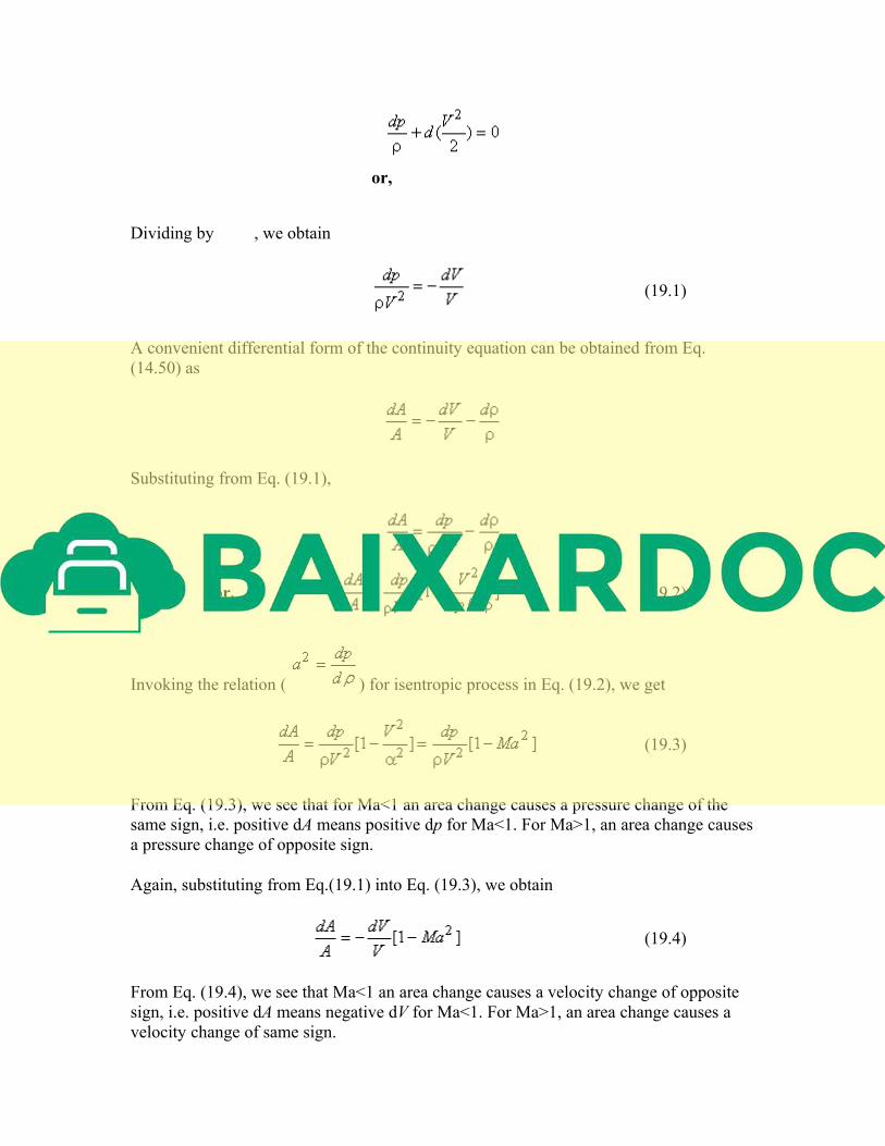
These results are summarized in Fig.19.1, and the relations (19.3) and (19.4) lead to the
following important conclusions about compressible flows:
1. At subsonic speeds (Ma<1) a decrease in area increases the speed of flow. A
subsonic nozzle should have a convergent profile and a subsonic diffuser should
possess a divergent profile. The flow behaviour in the regime of Ma<1 is
therefore qualitatively the same as in incompressible flows.
2. In supersonic flows (Ma>1), the effect of area changes are different. According to
Eq. (19.4), a supersonic nozzle must be built with an increasing area in the flow
direction. A supersonic diffuser must be a converging channel. Divergent nozzles
are used to produce supersonic flow in missiles and launch vehicles.
Fig 19.1Shapes of nozzles and diffusersin subsonic and
supersonic regimes
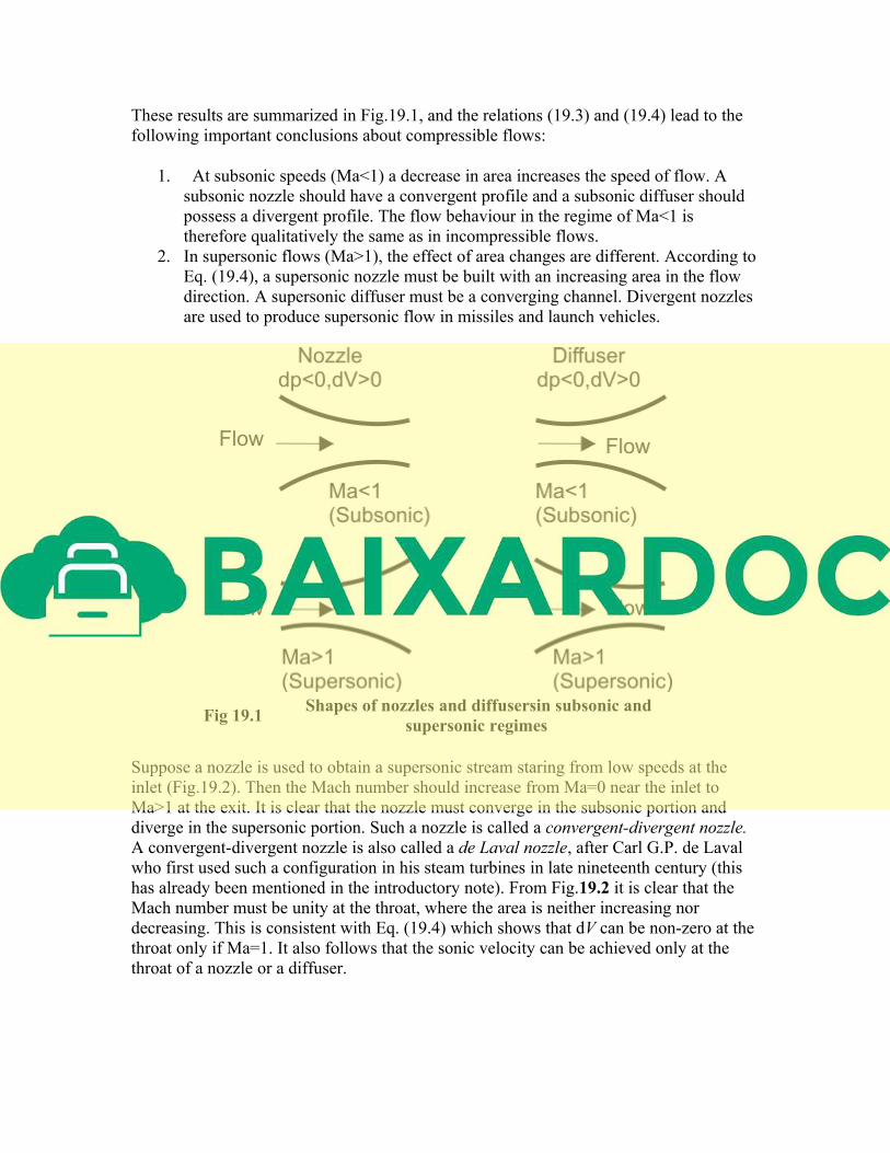
Suppose a nozzle is used to obtain a supersonic stream staring from low speeds at the
inlet (Fig.19.2). Then the Mach number should increase from Ma=0 near the inlet to
Ma>1 at the exit. It is clear that the nozzle must converge in the subsonic portion and
diverge in the supersonic portion. Such a nozzle is called a convergent-divergent nozzle.
A convergent-divergent nozzle is also called a de Laval nozzle, after Carl G.P. de Laval
who first used such a configuration in his steam turbines in late nineteenth century (this
has already been mentioned in the introductory note). From Fig.19.2 it is clear that the
Mach number must be unity at the throat, where the area is neither increasing nor
decreasing. This is consistent with Eq. (19.4) which shows that dV can be non-zero at the
throat only if Ma=1. It also follows that the sonic velocity can be achieved only at the
throat of a nozzle or a diffuser.
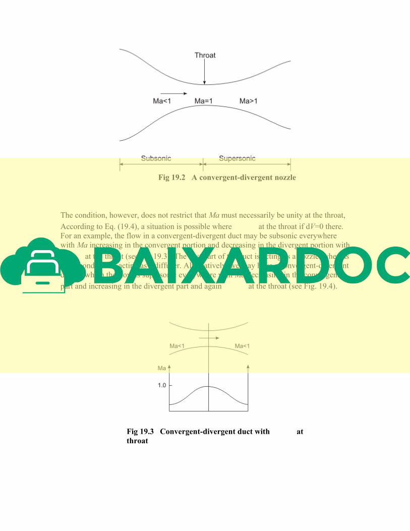
Fig 19.2 A convergent-divergent nozzle
The condition, however, does not restrict that Ma must necessarily be unity at the throat,
According to Eq. (19.4), a situation is possible where at the throat if dV=0 there.
For an example, the flow in a convergent-divergent duct may be subsonic everywhere
with Ma increasing in the convergent portion and decreasing in the divergent portion with
at the throat (see Fig.19.3). The first part of the duct is acting as a nozzle, whereas
the second part is acting as a diffuser. Alternatively, we may have a convergent-divergent
duct in which the flow is supersonic everywhere with Ma decreasing in the convergent
part and increasing in the divergent part and again at the throat (see Fig. 19.4).
Fig 19.3 Convergent-divergent duct with at
throat
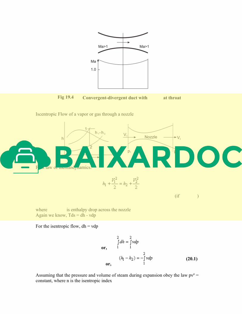
Fig 19.4 Convergent-divergent duct with at throat
Iscentropic Flow of a vapor or gas through a nozzle
First law of thermodynamics:
(if )
where is enthalpy drop across the nozzle
Again we know, Tds = dh - νdp
For the isentropic flow, dh = νdp
or,
or, (20.1)
Assuming that the pressure and volume of steam during expansion obey the law pνn =
constant, where n is the isentropic index
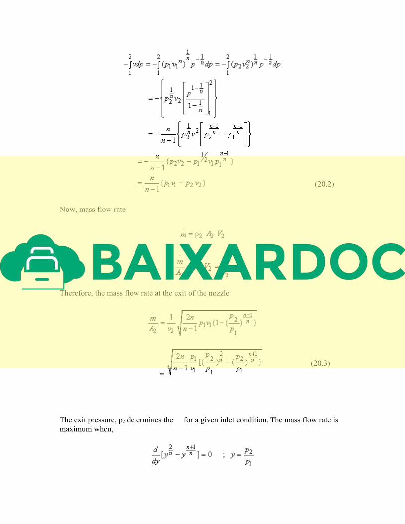
(20.2)
Now, mass flow rate
Therefore, the mass flow rate at the exit of the nozzle
=
(20.3)
The exit pressure, p2 determines the for a given inlet condition. The mass flow rate is
maximum when,
For maximum ,
(20.4)
n = 1.4, for diatomic gases
for super saturated steam
for dry saturated steam
for wet steam with dryness fraction x
For , (50%drop in inlet pressure)
If we compare this with the results of sonic properties, as described in the earlier section,
we shall observe that the critical pressure occurs at the throat for Ma = 1. The critical
pressure ratio is defined as the ratio of pressure at the throat to the inlet pressure, for
checked flow when Ma = 1
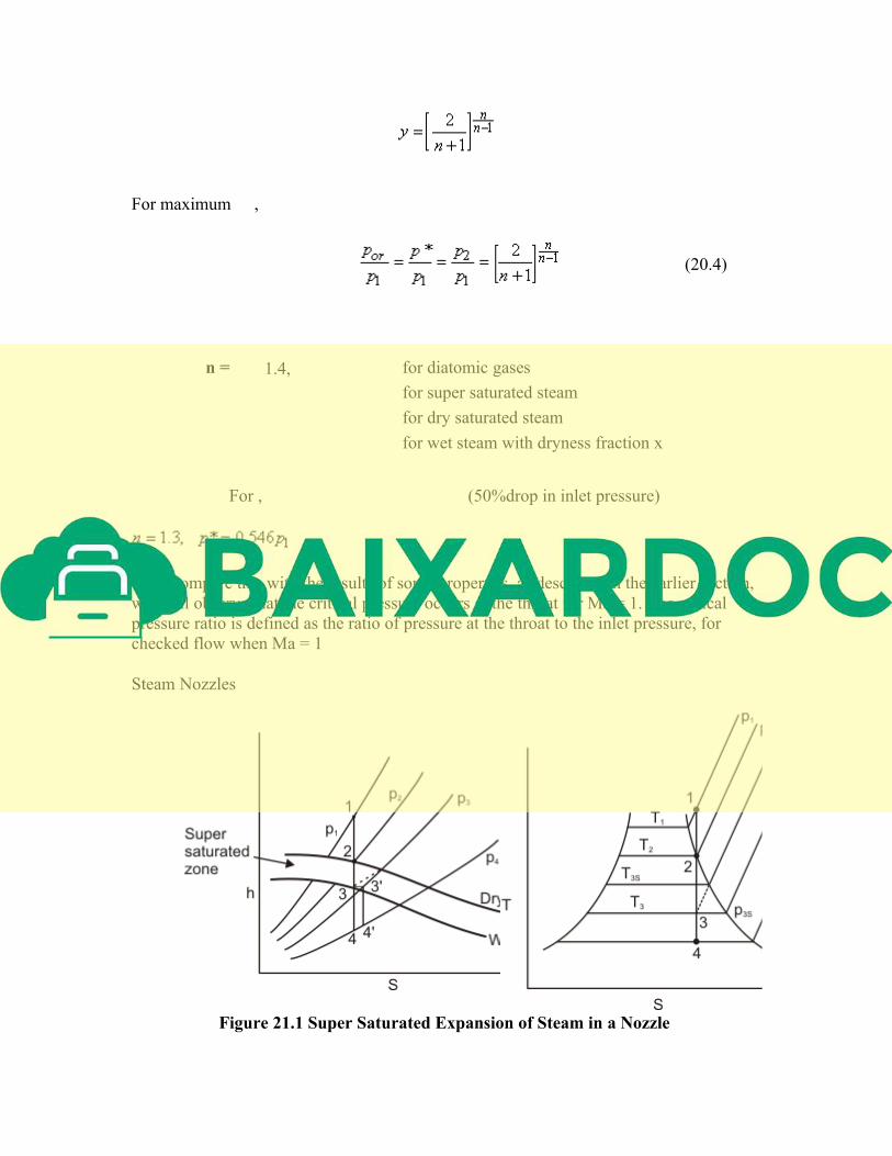
Steam Nozzles
Figure 21.1 Super Saturated Expansion of Steam in a Nozzle
Related Documents