TECHNICAL REPORT AD ________________ NATICK/TR-09/023 STEAM-JET CHILLER FOR ARMY FIELD KITCHENS by David Brownell Yankee Scientific, Incorporated Medfield, MA 02052 August 2009 Final Report November 2005 – December 2007 Approved for public release; distribution is unlimited. Prepared for U.S. Army Natick Soldier Research, Development and Engineering Center Natick, Massachusetts 01760-5018

Welcome message from author
This document is posted to help you gain knowledge. Please leave a comment to let me know what you think about it! Share it to your friends and learn new things together.
Transcript

TECHNICAL REPORT AD ________________ NATICK/TR-09/023
STEAM-JET CHILLER FOR ARMY FIELD KITCHENS
by
David Brownell
Yankee Scientific, Incorporated
Medfield, MA 02052
August 2009
Final Report November 2005 – December 2007
Approved for public release; distribution is unlimited.
Prepared for U.S. Army Natick Soldier Research, Development and Engineering Center Natick, Massachusetts 01760-5018
DlSCLAIMERS
The findings contained in this report are not to
be construed as an official Department of the Army
position unless so designated by other authorized
docwnents.
Citation oftrade names in this report does not
constitute an official endorsement or approval of
the use ofsuch items.
DESTRUCTION NOTICE
For Classified Doctmlents:
Follow the procedures in DoD 5200.22·M, Industrial
Security Manual, Section Il-19 or DoD 5200.1-R,
Infonnation Security Program Regulation, Chapter IX.
For Unclassified!Limited Distribution Doc\DPent§:
Destroy by any method that prevents discloswe of
contents or reconstruction ofthe document.
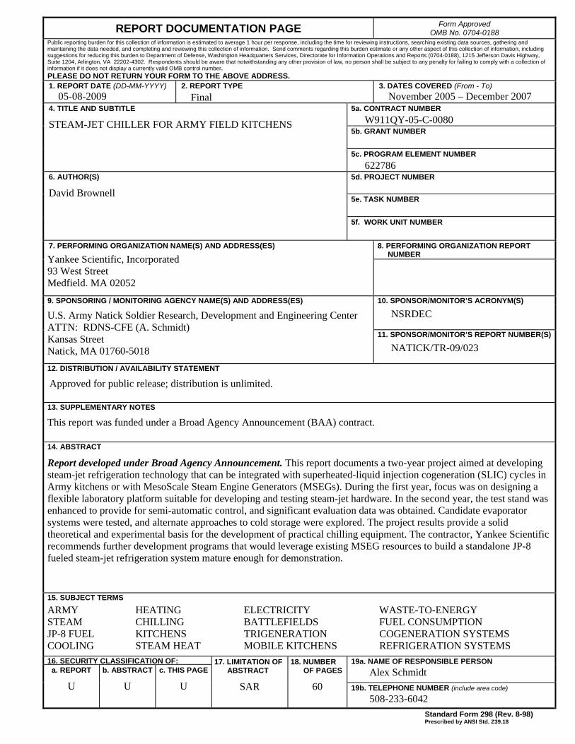
REPORT DOCUMENTATION PAGE Form Approved OMB No. 0704-0188
Public reporting burden for this collection of information is estimated to average 1 hour per response, including the time for reviewing instructions, searching existing data sources, gathering and maintaining the data needed, and completing and reviewing this collection of information. Send comments regarding this burden estimate or any other aspect of this collection of information, including suggestions for reducing this burden to Department of Defense, Washington Headquarters Services, Directorate for Information Operations and Reports (0704-0188), 1215 Jefferson Davis Highway, Suite 1204, Arlington, VA 22202-4302. Respondents should be aware that notwithstanding any other provision of law, no person shall be subject to any penalty for failing to comply with a collection of information if it does not display a currently valid OMB control number.
PLEASE DO NOT RETURN YOUR FORM TO THE ABOVE ADDRESS. 1. REPORT DATE (DD-MM-YYYY)
05-08-2009 2. REPORT TYPE
Final 3. DATES COVERED (From - To)
November 2005 – December 2007 5a. CONTRACT NUMBER
W911QY-05-C-0080 5b. GRANT NUMBER
4. TITLE AND SUBTITLE
STEAM-JET CHILLER FOR ARMY FIELD KITCHENS
5c. PROGRAM ELEMENT NUMBER
622786 5d. PROJECT NUMBER
5e. TASK NUMBER
6. AUTHOR(S)
David Brownell
5f. WORK UNIT NUMBER
7. PERFORMING ORGANIZATION NAME(S) AND ADDRESS(ES)
8. PERFORMING ORGANIZATION REPORT NUMBER
9. SPONSORING / MONITORING AGENCY NAME(S) AND ADDRESS(ES) 10. SPONSOR/MONITOR’S ACRONYM(S)
NSRDEC U.S. Army Natick Soldier Research, Development and Engineering Center ATTN: RDNS-CFE (A. Schmidt) Kansas Street Natick, MA 01760-5018
11. SPONSOR/MONITOR’S REPORT NUMBER(S)
NATICK/TR-09/023
12. DISTRIBUTION / AVAILABILITY STATEMENT
Approved for public release; distribution is unlimited.
13. SUPPLEMENTARY NOTES
This report was funded under a Broad Agency Announcement (BAA) contract.
14. ABSTRACT
Report developed under Broad Agency Announcement. This report documents a two-year project aimed at developing steam-jet refrigeration technology that can be integrated with superheated-liquid injection cogeneration (SLIC) cycles in Army kitchens or with MesoScale Steam Engine Generators (MSEGs). During the first year, focus was on designing a flexible laboratory platform suitable for developing and testing steam-jet hardware. In the second year, the test stand was enhanced to provide for semi-automatic control, and significant evaluation data was obtained. Candidate evaporator systems were tested, and alternate approaches to cold storage were explored. The project results provide a solid theoretical and experimental basis for the development of practical chilling equipment. The contractor, Yankee Scientific recommends further development programs that would leverage existing MSEG resources to build a standalone JP-8 fueled steam-jet refrigeration system mature enough for demonstration.
15. SUBJECT TERMS
16. SECURITY CLASSIFICATION OF: 19a. NAME OF RESPONSIBLE PERSON
Alex Schmidt a. REPORT
U
b. ABSTRACT
U
c. THIS PAGE
U
17. LIMITATION OF ABSTRACT
SAR
18. NUMBER OF PAGES
60 19b. TELEPHONE NUMBER (include area code) 508-233-6042
Standard Form 298 (Rev. 8-98) Prescribed by ANSI Std. Z39.18
ARMY HEATING ELECTRICITY WASTE-TO-ENERGY STEAM CHILLING BATTLEFIELDS FUEL CONSUMPTION JP-8 FUEL KITCHENS TRIGENERATION COGENERATION SYSTEMS COOLING STEAM HEAT MOBILE KITCHENS REFRIGERATION SYSTEMS
Yankee Scientific, Incorporated 93 West Street Medfield, MA 02052

(This page inserted for layout purposes.)
iii
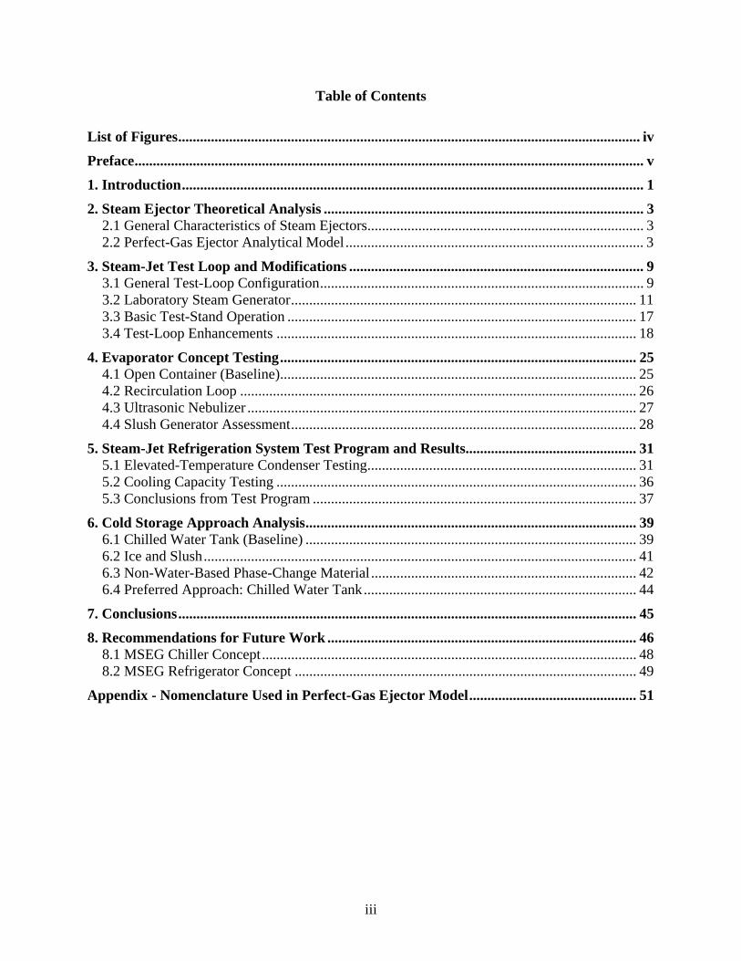
Table of Contents
List of Figures............................................................................................................................... iv
Preface............................................................................................................................................ v
1. Introduction............................................................................................................................... 1
2. Steam Ejector Theoretical Analysis ........................................................................................ 3 2.1 General Characteristics of Steam Ejectors............................................................................ 3 2.2 Perfect-Gas Ejector Analytical Model .................................................................................. 3
3. Steam-Jet Test Loop and Modifications ................................................................................. 9 3.1 General Test-Loop Configuration......................................................................................... 9 3.2 Laboratory Steam Generator............................................................................................... 11 3.3 Basic Test-Stand Operation ................................................................................................ 17 3.4 Test-Loop Enhancements ................................................................................................... 18
4. Evaporator Concept Testing.................................................................................................. 25 4.1 Open Container (Baseline).................................................................................................. 25 4.2 Recirculation Loop ............................................................................................................. 26 4.3 Ultrasonic Nebulizer ........................................................................................................... 27 4.4 Slush Generator Assessment............................................................................................... 28
5. Steam-Jet Refrigeration System Test Program and Results............................................... 31 5.1 Elevated-Temperature Condenser Testing.......................................................................... 31 5.2 Cooling Capacity Testing ................................................................................................... 36 5.3 Conclusions from Test Program ......................................................................................... 37
6. Cold Storage Approach Analysis........................................................................................... 39 6.1 Chilled Water Tank (Baseline) ........................................................................................... 39 6.2 Ice and Slush....................................................................................................................... 41 6.3 Non-Water-Based Phase-Change Material ......................................................................... 42 6.4 Preferred Approach: Chilled Water Tank........................................................................... 44
7. Conclusions.............................................................................................................................. 45
8. Recommendations for Future Work ..................................................................................... 46 8.1 MSEG Chiller Concept....................................................................................................... 48 8.2 MSEG Refrigerator Concept .............................................................................................. 49
Appendix - Nomenclature Used in Perfect-Gas Ejector Model.............................................. 51

iv
List of Figures
Figure 1. Steam-Jet Chiller Integrated with SLIC System ...........................................................2 Figure 2. Motive Steam Supersonic Nozzle .................................................................................4 Figure 3. Nomenclature for Steam-Jet Analysis...........................................................................5 Figure 4. Excel VBA Program for Solving Ejector Model ..........................................................8 Figure 5. Steam-Jet Chiller Test Stand.........................................................................................9 Figure 6. Steam-Jet Test-Loop Schematic..................................................................................10 Figure 7. Laboratory Steam Boiler .............................................................................................11 Figure 8. Abbess Vacuum Chamber...........................................................................................12 Figure 9. Shell and Tube Condenser ..........................................................................................13 Figure 10. Vacuum Condensate Sump .........................................................................................14 Figure 11. Custom Primary Ejector for Steam-Jet Chiller Evaluation .........................................15 Figure 12. Cutaway View of Custom Ejector...............................................................................16 Figure 13. Low-Pressure Ejector Nozzle......................................................................................16 Figure 14. Electrical Schematic for Steam-Jet Test Loop ............................................................17 Figure 15. Iwaki Boost Pump with Shurflo Primary Pump..........................................................18 Figure 16. Condenser Cooling-Water Recirculating Temperature Control..................................19 Figure 17. Schematic of Evaporator with Immersion Water Heater ............................................20 Figure 18. Heater and Baffles for Evaporator Chamber...............................................................20 Figure 19. Overall Test Stand with Insulation and Updated Instrumentation ..............................21 Figure 20. Equalizer Line .............................................................................................................22 Figure 21. Relocated Digital and Mechanical Vacuum Gauges...................................................23 Figure 22. Vacuum Indicators ......................................................................................................24 Figure 23. Surface Ice Water ........................................................................................................25 Figure 24. Water Container with Baffle .......................................................................................26 Figure 25. Evaporator Recirculation Loop ...................................................................................27 Figure 26. Submersible Ultrasonic Nebulizer ..............................................................................28 Figure 27. Ice Slush Generator .....................................................................................................29 Figure 28. Slush Maker Inside Generator.....................................................................................29 Figure 29. Slush Produced During Testing ..................................................................................30 Figure 30. Empirical vs. Model Data for 100-psig Nozzle...........................................................32 Figure 31. Evaporator and Condenser Pressures for 100-psig Nozzle .........................................33 Figure 32. Evaporator and Condenser Temperatures for 100-psig Nozzle ..................................33 Figure 33. Empirical Data vs. Model for 25-psig Nozzle ............................................................34 Figure 34. Evaporator and Condenser Pressure for 25-psig Nozzle.............................................35 Figure 35. Evaporator and Condenser Temperatures for 25-psig Nozzle ....................................36 Figure 36. Water Cooling-Rate Curve..........................................................................................37 Figure 37. Evaporator Circulation Loop.......................................................................................39 Figure 38. Cooling Rate Curve for a 32-Gal Tank .......................................................................40 Figure 39. Ice-Slush Cold Storage System Layout.......................................................................41 Figure 40. PCM Properties of EPS Ltd. Products ........................................................................43 Figure 41. Evaporator Recirculation Loop ...................................................................................44 Figure 42. MSEG Demonstration Unit.........................................................................................46 Figure 43. Schematic of Suggested MSEG/Steam-Jet Integration...............................................47 Figure 44. MSEG/SJ Water-Cooler/Generator.............................................................................48 Figure 45. MSEG/SJ Refrigerator ................................................................................................49

v
Preface
This report documents a 2-year Broad Agency Announcement (BAA) project aimed at furthering development of steam-jet refrigeration technology for integration with superheated liquid injection cogeneration (SLIC) cycles in Army kitchens. The work was performed by Yankee Scientific, during the period November 2005 to December 2007, under contract number W911QY-05-C-0080 awarded by the U.S. Army Natick Soldier Research, Development and Engineering Center (NSRDEC), under program element number 622786. Yankee developed the concept of steam-jet driven refrigeration during a Phase I Small Business Innovation Research SBIR contract, between December 2002 and 2003, also awarded by NSRDEC. The results are published in technical report NATICK/TR-07/014L entitled Heat-Driven Steam-Jet Cooling Cycle for Remote Refrigeration - Phase I. A Phase II was not contractawarded due to funding issues.

vi
(This page inserted for layout purposes.)
1
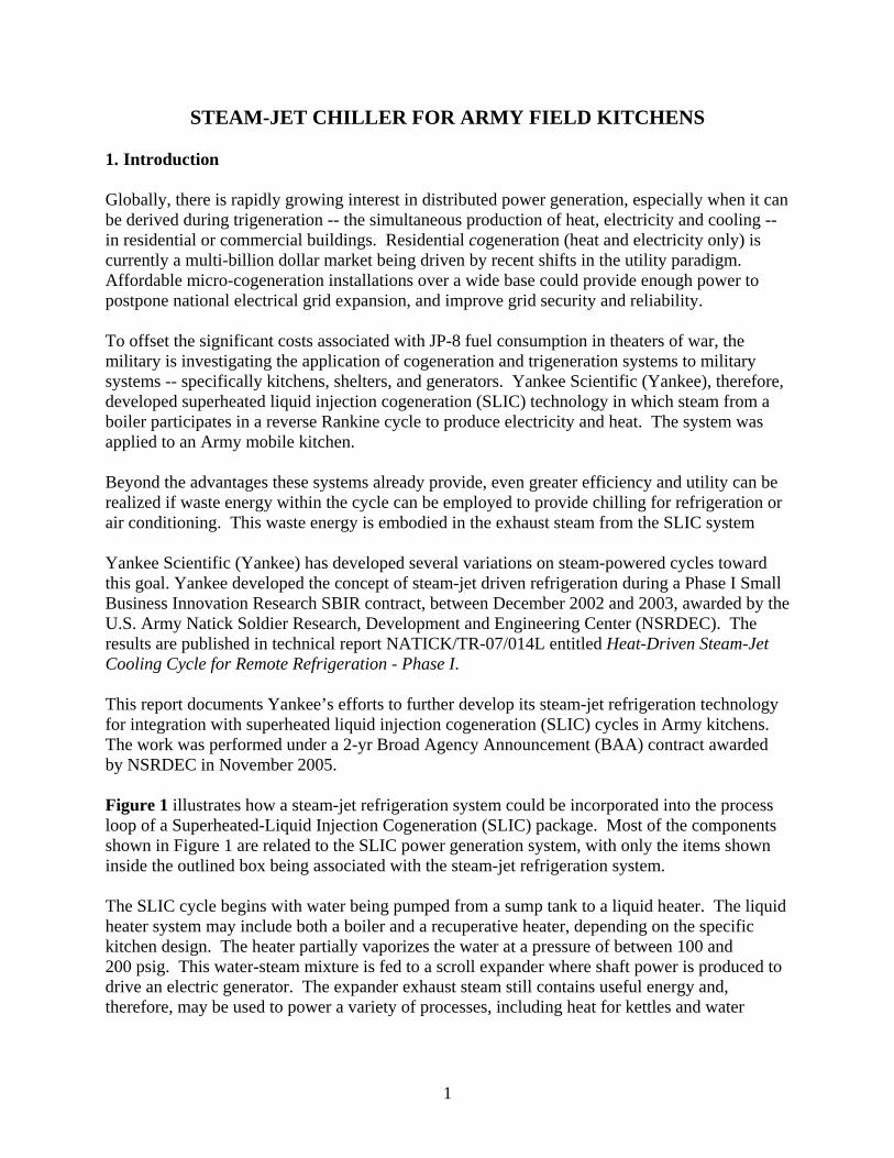
STEAM-JET CHILLER FOR ARMY FIELD KITCHENS 1. Introduction Globally, there is rapidly growing interest in distributed power generation, especially when it can be derived during trigeneration -- the simultaneous production of heat, electricity and cooling -- in residential or commercial buildings. Residential cogeneration (heat and electricity only) is currently a multi-billion dollar market being driven by recent shifts in the utility paradigm. Affordable micro-cogeneration installations over a wide base could provide enough power to postpone national electrical grid expansion, and improve grid security and reliability. To offset the significant costs associated with JP-8 fuel consumption in theaters of war, the military is investigating the application of cogeneration and trigeneration systems to military systems -- specifically kitchens, shelters, and generators. Yankee Scientific (Yankee), therefore, developed superheated liquid injection cogeneration (SLIC) technology in which steam from a boiler participates in a reverse Rankine cycle to produce electricity and heat. The system was applied to an Army mobile kitchen. Beyond the advantages these systems already provide, even greater efficiency and utility can be realized if waste energy within the cycle can be employed to provide chilling for refrigeration or air conditioning. This waste energy is embodied in the exhaust steam from the SLIC system Yankee Scientific (Yankee) has developed several variations on steam-powered cycles toward this goal. Yankee developed the concept of steam-jet driven refrigeration during a Phase I Small Business Innovation Research SBIR contract, between December 2002 and 2003, awarded by the U.S. Army Natick Soldier Research, Development and Engineering Center (NSRDEC). The results are published in technical report NATICK/TR-07/014L entitled Heat-Driven Steam-Jet Cooling Cycle for Remote Refrigeration - Phase I. This report documents Yankee’s efforts to further develop its steam-jet refrigeration technology for integration with superheated liquid injection cogeneration (SLIC) cycles in Army kitchens. The work was performed under a 2-yr Broad Agency Announcement (BAA) contract awarded by NSRDEC in November 2005. Figure 1 illustrates how a steam-jet refrigeration system could be incorporated into the process loop of a Superheated-Liquid Injection Cogeneration (SLIC) package. Most of the components shown in Figure 1 are related to the SLIC power generation system, with only the items shown inside the outlined box being associated with the steam-jet refrigeration system. The SLIC cycle begins with water being pumped from a sump tank to a liquid heater. The liquid heater system may include both a boiler and a recuperative heater, depending on the specific kitchen design. The heater partially vaporizes the water at a pressure of between 100 and 200 psig. This water-steam mixture is fed to a scroll expander where shaft power is produced to drive an electric generator. The expander exhaust steam still contains useful energy and, therefore, may be used to power a variety of processes, including heat for kettles and water
2
heaters, as well as to drive a steam-jet refrigeration system. If there is not sufficient need for all the heat, there is a provision for rejecting excess heat to ambient using a trim cooler.
Figure 1. Steam-Jet Chiller Integrated with SLIC System
Incorporation of a steam-jet refrigeration system into a SLIC requires addition of an evaporator chamber, the steam-jet ejector, and a condenser for rejecting heat to ambient. A portion of the SLIC steam supply is directed to the steam-jet ejector where it creates a suction effect pulling the evaporator pressure down to as low as 0.09 psia. This exhaust steam from the ejector will be at 0.95 psia and thus can be condensed at about 100°F. The condensate drains into a receiver vessel and can then be pumped back to the SLIC cycle sump. A small amount of this water is used to supply makeup water for the evaporator. The cold evaporator water can be used to provide refrigeration for either a beverage cooler or the refrigerator.
section break (even)

3
2. Steam Ejector Theoretical Analysis The modeling tools developed in this program allow extrapolation of the experimental data toward optimizing design of the ejector. This analysis is based on a perfect-gas model of the fluids and assumes the geometry of the mixing zone is such that the pressure within it remains constant. Alternate mixing-zone pressure assumptions are possible, but the constant pressure constraint yields good performance.
2.1 General Characteristics of Steam Ejectors An ejector is essentially a compressor with no moving parts. The energy in the motive (high-pressure supply steam) fluid is used to boost the pressure of the suction fluid up to a pressure between the supply steam pressure and the suction pressure. The ratio of the exhaust pressure to the suction pressure is the compression ratio for the ejector. The objective of an ejector analysis is to determine what the suction pressure and suction mass flow will be for a given geometry and steam supply and exhaust conditions. In other words, how low a vacuum can be created and how much water vapor can be drawn from a vacuumed space for a given ejector geometry and the inlet steam and exhaust conditions.
2.2 Perfect-Gas Ejector Analytical Model Generally, the analyses described in this section assume the motive and suction gases are ideal gases with constant specific heats, and the flow can be treated as one-dimensional and is adiabatic. In addition, except for the normal shock, the flow is considered to be isentropic. All variables are defined in the Nomenclature Used in Perfect-Gas Ejector Model. The ejector analysis is described in the following subsections in four topics: (1) the motive gas nozzle, (2) the mixing process, (3) the normal shock (if present) and (4) the diffuser expansion.
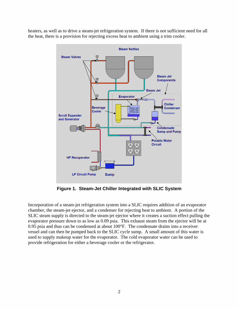
2.2.1 Motive Steam Supersonic Nozzle Analysis The nozzle shown in Figure 2, often called a "de Laval" nozzle, is intended to convert the potential energy of a high-pressure reservoir (1) into kinetic energy in the flow stream at the nozzle exit (3). It is assumed that the fluid at the inlet is essentially at rest, and that the measured pressure and temperature are the stagnation values, P01 and T01. This analysis will determine the mass flow rate of motive steam, W, which will enter the supersonic nozzle when operating at the assumed inlet conditions. The exit pressure is assumed to be low enough to force the nozzle to operate in the supersonic mode. As the subsonic flow enters the nozzle, it is accelerated isentropically to sonic velocity by the reduction in flow area; therefore, the velocity at the throat area (2) will be the local speed of sound.
4
V2 = C2P2
V1 ~ 0
Convergent Section
High Pressure Reservoir, P0a
( 1 )
Exhaust Reservoir, P03
Diffuser Section
Normal Shock
( 2 ) ( 3 )
Figure 2. Motive Steam Supersonic Nozzle
The mass flow through the nozzle will be: For a perfect gas the sonic velocity at the throat (2) will be:
where T2 and ρ2 are assumed to be isentropically expanded from stagnation conditions, and and
where,
Therefore, the mass flow through the nozzle at sonic conditions will be:
2*2*2 ACW . ( 1 )
2*2 TRC , ( 2 )
)1/(2*012 TT ( 3 )
)1/(1))1/(2(*012 ( 4 )
)01/(0101 TRP . ( 5 )
011
2*2))1/(2()01/(01 )1/(1 TRATRPW
( 6 )
5
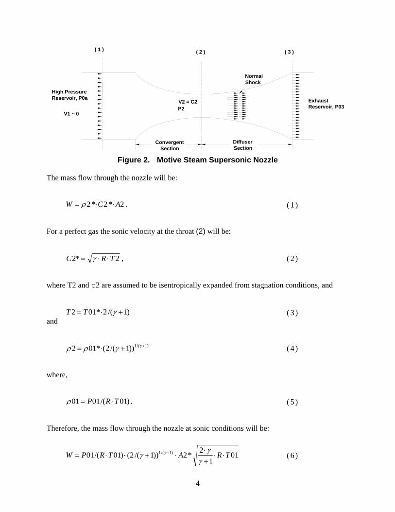
2.2.2 Ejector Mixing Analysis Figure 3 shows the basic nomenclature defining the ejector geometry and fluid conditions used in the analytical models. Fluid "a" is the higher pressure motive steam flow. Fluid "b" is the suction flow coming from the evaporator or vacuum chamber.
Motive Gas "a" P0a
P2 = P1
Constant Pressure
Mixing SectionSuction
Gas "b"
P0b
Nozzle
( t )
P1Exhaust P03
Diffuser Section
x y
Normal Shock
( 2 )( 1 ) ( 3 )
M=1
Figure 3. Nomenclature for Steam-Jet Analysis
The ejector mixing process is assumed to take place under constant pressure; therefore, the pressure at the ejector throat, P2, is assumed to be the same as for the nozzle exit plane, P1. In common practice, the pressure in the evaporator will be slightly higher than the pressure at location (1) so that a net suction flow will occur. The pressure ratio P1/P0b is defined as X, and will usually be in the range of 0.9 to 1.0. The governing one-dimensional equations of conservation of mass, momentum and energy for adiabatic ideal gas flows between cross sections (1) and (2) are: representing conservation of mass, representing conservation of momentum, and
222111111 VAbVbAbaVaAa , ( 7 )
2222
1111
APg
VWAP
g
bVWb
g
aVWa
, ( 8 )
6
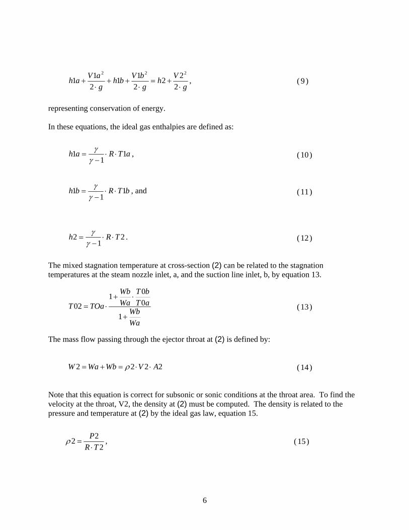
representing conservation of energy. In these equations, the ideal gas enthalpies are defined as: The mixed stagnation temperature at cross-section (2) can be related to the stagnation temperatures at the steam nozzle inlet, a, and the suction line inlet, b, by equation 13. The mass flow passing through the ejector throat at (2) is defined by: Note that this equation is correct for subsonic or sonic conditions at the throat area. To find the velocity at the throat, V2, the density at (2) must be computed. The density is related to the pressure and temperature at (2) by the ideal gas law, equation 15.
g
Vh
g
bVbh
g
aVah
2
22
2
11
2
11
222
, ( 9 )
aTRah 11
1
, ( 10 )
bTRbh 11
1
, and ( 11 )
21
2 TRh
. ( 12 )
Wa
WbaT
bT
Wa
Wb
TOaT
1
0
01
02 ( 13 )
2222 AVWbWaW ( 14 )
2
22
TR
P
, ( 15 )

7
And for a gas traveling at a mach number of M2 the temperature T2 will be:
The pressure at (2) is assumed to be the same as the pressure at (1) because there will be constant pressure mixing, and the pressure at (1) is assumed to be the ratio X times the suction stagnation pressure; this results in equation 17.
Combining equations 16 and 17, and solving for the density at (2) yields and the equation for velocity at (2) can be written as This equation yields a range of velocities at the throat for subsonic flows, but for the case where the flow is sonic at the throat -- a desirable operating condition for effective compression of the suction gas in the diffuser -- the Mach number will be 1 and the velocity at (2) will be This is the final result needed to define the mixed characteristics of the flow at the point where the flow can now undergo expansion in the diffuser with an associated normal shock.
2.2.3 Normal Shock and Diffuser Analysis An important characteristic of a well-designed steam-driven ejector is that it should be able to establish a stable normal shock in the diffuser because it significantly increases the pressure rise in the diffuser over what would be possible without the shock. The pressure, temperature and density of a flow of a calorically perfect gas after experiencing a normal shock is related only to the value of the property and the Mach number of the flow entering the shock. These relationships are well known and are listed below, using the subscript "x" for before the shock and "y" for after the shock:
222
11
022
M
TT
.
( 16 )
bPXPP 021 ( 17 )
02
)21
1(*0
2
2
TR
MbPX
, ( 18 )
02
22
11
02
22
2
T
M
bPXA
RWV
. ( 19 )
022
11
02
22
TbPXA
RWV
. ( 20 )
8
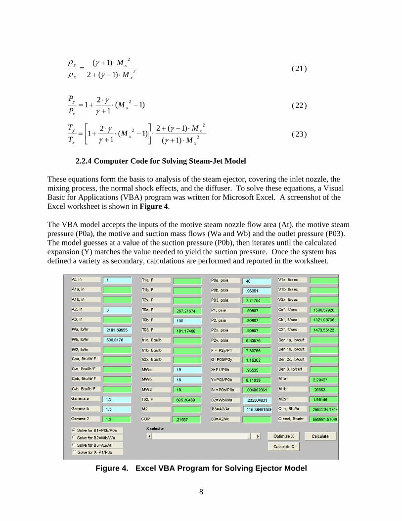
2.2.4 Computer Code for Solving Steam-Jet Model These equations form the basis to analysis of the steam ejector, covering the inlet nozzle, the mixing process, the normal shock effects, and the diffuser. To solve these equations, a Visual Basic for Applications (VBA) program was written for Microsoft Excel. A screenshot of the Excel worksheet is shown in Figure 4. The VBA model accepts the inputs of the motive steam nozzle flow area (At), the motive steam pressure (P0a), the motive and suction mass flows (Wa and Wb) and the outlet pressure (P03). The model guesses at a value of the suction pressure (P0b), then iterates until the calculated expansion (Y) matches the value needed to yield the suction pressure. Once the system has defined a variety as secondary, calculations are performed and reported in the worksheet.
Figure 4. Excel VBA Program for Solving Ejector Model
2
2
)1(2
)1(
x
x
x
y
M
M
( 21 )
)1(1
21 2
xx
y MP
P
( 22 )
2
22
)1(
)1(2)1(
1
21
x
xx
x
y
M
MM
T
T
( 23 )
9
3. Steam-Jet Test Loop and Modifications
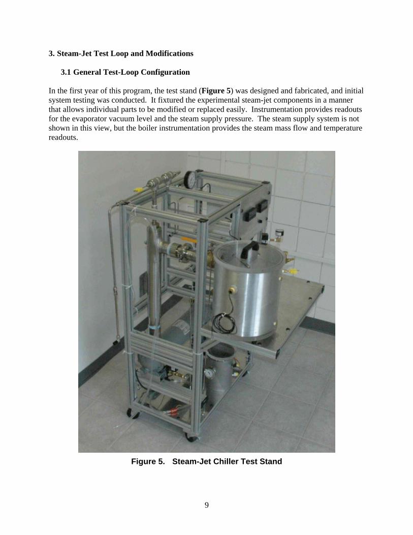
3.1 General Test-Loop Configuration In the first year of this program, the test stand (Figure 5) was designed and fabricated, and initial system testing was conducted. It fixtured the experimental steam-jet components in a manner that allows individual parts to be modified or replaced easily. Instrumentation provides readouts for the evaporator vacuum level and the steam supply pressure. The steam supply system is not shown in this view, but the boiler instrumentation provides the steam mass flow and temperature readouts.
Figure 5. Steam-Jet Chiller Test Stand

10
The frame wass constructed with an extruded-aluminum T-slotted framing system supplied by 80/20, Inc. It supports the evaporator (vacuum chamber), the steam-jet, the water sump, the condenser and the instrumentation package. The schematic in Figure 6 shows how each of these components is connected.
Figure 6. Steam-Jet Test-Loop Schematic
A vacuum pump removes air from the entire system on startup, and is occasionally used to expel air during operation. Once the system is evacuated, the cooling water is applied to the condenser, and the boiler is started. Steam is delivered to the steam-jet inlet nozzle; this creates a strong vacuum in the evaporator vessel. The primary steam and water vapor evaporated within the evaporator chamber are delivered to the tube and shell condenser. The steam is condensed and drains to the vacuum sump tank.
11
Periodically, the condensate pump will operate and transfer water from the sump back to the boiler. Two float switches in the sump are used, along with basic relay logic, to start the sump pump when the level reaches an upper limit and shut it off when the lower level limit is reached.
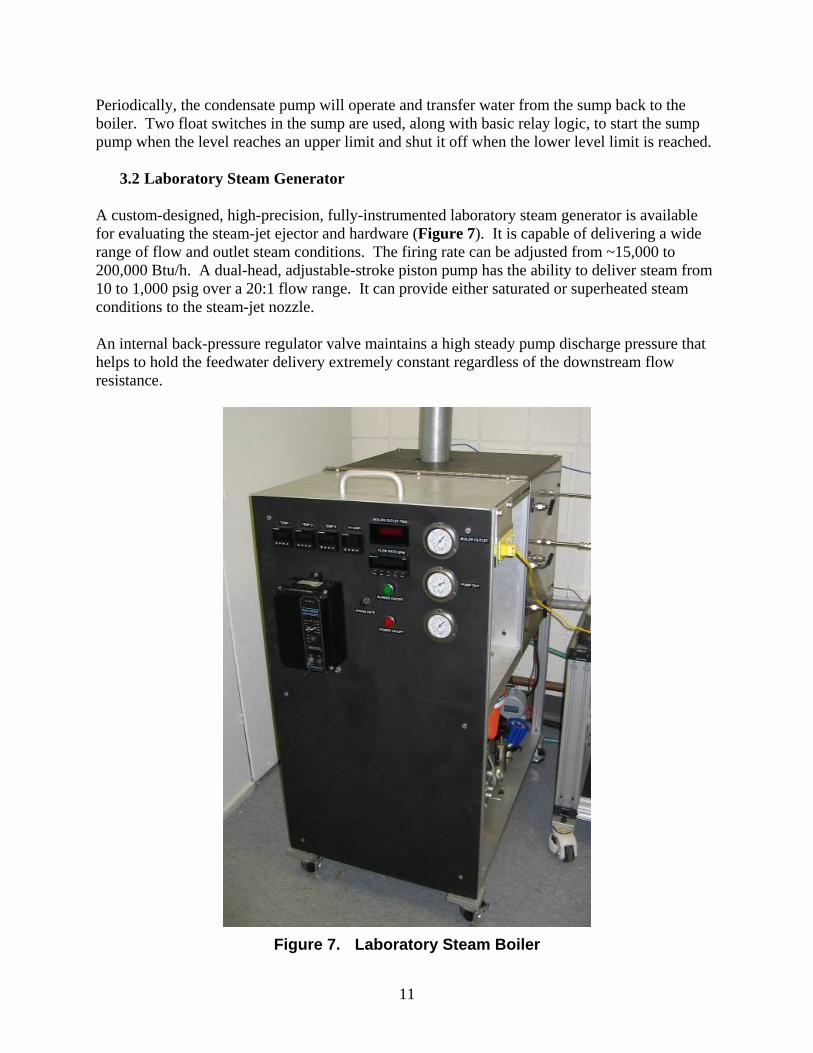
3.2 Laboratory Steam Generator A custom-designed, high-precision, fully-instrumented laboratory steam generator is available for evaluating the steam-jet ejector and hardware (Figure 7). It is capable of delivering a wide range of flow and outlet steam conditions. The firing rate can be adjusted from ~15,000 to 200,000 Btu/h. A dual-head, adjustable-stroke piston pump has the ability to deliver steam from 10 to 1,000 psig over a 20:1 flow range. It can provide either saturated or superheated steam conditions to the steam-jet nozzle. An internal back-pressure regulator valve maintains a high steady pump discharge pressure that helps to hold the feedwater delivery extremely constant regardless of the downstream flow resistance.
Figure 7. Laboratory Steam Boiler
12
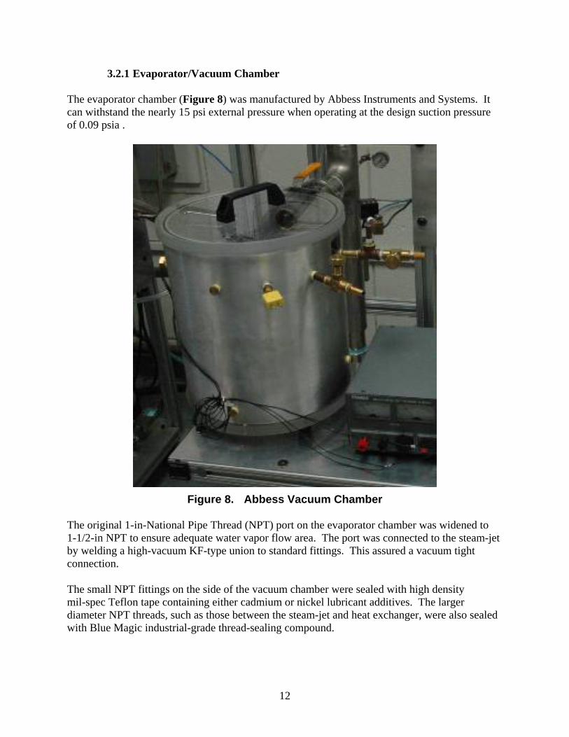
3.2.1 Evaporator/Vacuum Chamber The evaporator chamber (Figure 8) was manufactured by Abbess Instruments and Systems. It can withstand the nearly 15 psi external pressure when operating at the design suction pressure of 0.09 psia .
Figure 8. Abbess Vacuum Chamber
The original 1-in-National Pipe Thread (NPT) port on the evaporator chamber was widened to 1-1/2-in NPT to ensure adequate water vapor flow area. The port was connected to the steam-jet by welding a high-vacuum KF-type union to standard fittings. This assured a vacuum tight connection. The small NPT fittings on the side of the vacuum chamber were sealed with high density mil-spec Teflon tape containing either cadmium or nickel lubricant additives. The larger diameter NPT threads, such as those between the steam-jet and heat exchanger, were also sealed with Blue Magic industrial-grade thread-sealing compound.
13
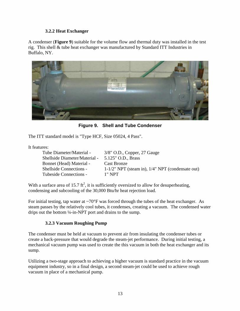
3.2.2 Heat Exchanger A condenser (Figure 9) suitable for the volume flow and thermal duty was installed in the test rig. This shell & tube heat exchanger was manufactured by Standard ITT Industries in Buffalo, NY.
Figure 9. Shell and Tube Condenser
The ITT standard model is "Type HCF, Size 05024, 4 Pass". It features:
Tube Diameter/Material - 3/8" O.D., Copper, 27 Gauge Shellside Diameter/Material - 5.125" O.D., Brass Bonnet (Head) Material - Cast Bronze Shellside Connections - 1-1/2" NPT (steam in), 1/4" NPT (condensate out) Tubeside Connections - 1" NPT
With a surface area of 15.7 ft2, it is sufficiently oversized to allow for desuperheating, condensing and subcooling of the 30,000 Btu/hr heat rejection load. For initial testing, tap water at ~70°F was forced through the tubes of the heat exchanger. As steam passes by the relatively cool tubes, it condenses, creating a vacuum. The condensed water drips out the bottom ¼-in-NPT port and drains to the sump.
3.2.3 Vacuum Roughing Pump The condenser must be held at vacuum to prevent air from insulating the condenser tubes or create a back-pressure that would degrade the steam-jet performance. During initial testing, a mechanical vacuum pump was used to create the this vacuum in both the heat exchanger and its sump. Utilizing a two-stage approach to achieving a higher vacuum is standard practice in the vacuum equipment industry, so in a final design, a second steam-jet could be used to achieve rough vacuum in place of a mechanical pump.

14
The mechanical vacuum roughing pump chosen was from Welch Vacuum, model number 2581B-24. It produces a maximum vacuum of 27.6 in-Hg. Once a rough vacuum of about 14 psi is achieved (approximately 2 min of vacuum pump operation) in the system, valves are closed and the vacuum pump is shut off to reduce power consumption. The steam-jet alone can then operate to create the higher vacuum needed for cooling the water in the evaporator down to the freezing point.
3.2.4 Vacuum Sump The sump (Figure 10) operates at nearly the same vacuum conditions as the condenser, so a 6"-in-diameter by 9-in-tall stainless steel vacuum chamber (part number LVC0609FP50-VI) was purchased from Laco Technologies. It is rated to 0.05 Torr.
Figure 10. Vacuum Condensate Sump
The stock vacuum chamber required modification for the application. Two ¼-in-NPT ports were added for water inlet and drain, and two ½-in-NPT ports were added for float switches which would monitor liquid level. The ports were drilled, then half-couplings were welded in. The float switches were connected through a relay logic circuit to the sump pump in such a manner that the pump would only turn on when the water level tripped the top float switch. The pump would then turn on until the water level lowered beneath the bottom float switch.
3.2.5 Sump Pump The sump pump (Shurflo model 4UN54) is a three-stage positive-displacement diaphragm pump similar to those used in commercial carpet cleaning machines. The pump can handle some

15
cavitation and is not damaged by running dry. Its available pressure head of 60 psi was sufficient to overcome the vacuum and raise the water to the level of the boiler’s feedwater tank. The maximum flow rate capacity of 1.4 gal/min was sufficient to empty the sump in less than 30 s, so its electric consumption at 115 VAC of 0.7 A is minimal. A normally-closed solenoid valve was installed in series with the pump to ensure there was no leakage back into the vacuum sump. The solenoid valve uses 14.5 VA at 120 VAC when open.
3.2.6 Custom Steam Ejector The pressure at the suction inlet of the primary ejector must be 0.09 psia or lower. Given that the typical maximum pressure lift for an ejector is about 10:1, this implies the main ejector must be able to compress the water vapor to a discharge pressure of 0.9 psia. The main design issue affecting the optimum shape of an ejector discharging to ~1 psia versus one discharging to atmospheric pressure (14.7 psia) is that the density of the gas passing through the ejector is about 15 times lower. For the same mass flow, this means the low discharge pressure ejector has to handle 15 times the volumetric flow rate. Based on analytical model evaluations and preliminary testing, it is clear the low-pressure ejector must be sized to handle this relatively high volumetric flow. The balance of this section describes a custom ejector that has been developed and successfully tested to meet this primary ejector application. Yankee contracted with the Fox Valve Company to manufacture a custom steam ejector (Figure 11) for this low discharge pressure application. Fox Valve makes a line of small industrial steam-jet systems for various industrial process applications. The ejector built by Fox Valve is based on their standard product line, but is sized to meet Yankee's requirements. The actual size of this ejector is approximately 3 in in diameter by 20 in long. A smaller ejector could work for the current application, but this size is the smallest that Fox Valve can presently fabricate.
Figure 11. Custom Primary Ejector for Steam-Jet Chiller Evaluation
The ejector is sized to draw 4 lb/h of water vapor at 0.09 psia (twice the flow theoretically required) with a discharge pressure of 0.9 psia. The high pressure steam inlet nozzle consumes

16
26 lb/h of steam at 100 psig. A cutaway drawing of the ejector, showing the replaceable nozzle, is shown in Figure 12.
SteamSupply
(100 psig)
Suction Port(0.09 psia)
CombinedFlow
Discharge(~1 psia)
Replaceable Supersonic
Steam Nozzle
Figure 12. Cutaway View of Custom Ejector
The steam inlet nozzle can be replaced with a modified supply nozzle designed to operate with a steam supply pressure of 25 psig. This modified ejector nozzle is shown in Figure 13. This nozzle will yield the same suction pressure and consume the same 26 lb/h of steam as the high pressure nozzle; however, it will draw only 2.1 lb/h of water vapor from the evaporator. Although this is not as efficient as the 100 psig nozzle, the low-pressure steam may be available as a waste product from the SLIC system. Thus, the energy cost of the lower pressure nozzle would be very attractive.
Figure 13. Low-pressure Ejector Nozzle
17
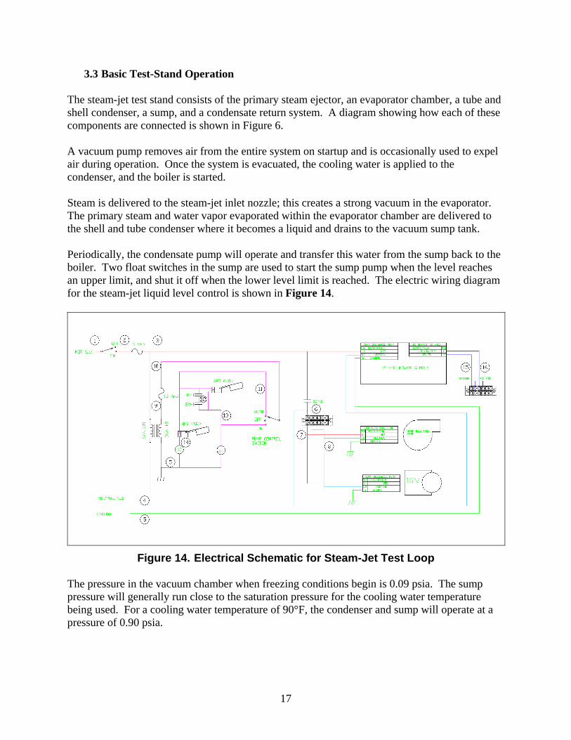
3.3 Basic Test-Stand Operation The steam-jet test stand consists of the primary steam ejector, an evaporator chamber, a tube and shell condenser, a sump, and a condensate return system. A diagram showing how each of these components are connected is shown in Figure 6. A vacuum pump removes air from the entire system on startup and is occasionally used to expel air during operation. Once the system is evacuated, the cooling water is applied to the condenser, and the boiler is started. Steam is delivered to the steam-jet inlet nozzle; this creates a strong vacuum in the evaporator. The primary steam and water vapor evaporated within the evaporator chamber are delivered to the shell and tube condenser where it becomes a liquid and drains to the vacuum sump tank. Periodically, the condensate pump will operate and transfer this water from the sump back to the boiler. Two float switches in the sump are used to start the sump pump when the level reaches an upper limit, and shut it off when the lower level limit is reached. The electric wiring diagram for the steam-jet liquid level control is shown in Figure 14.
Figure 14. Electrical Schematic for Steam-Jet Test Loop The pressure in the vacuum chamber when freezing conditions begin is 0.09 psia. The sump pressure will generally run close to the saturation pressure for the cooling water temperature being used. For a cooling water temperature of 90°F, the condenser and sump will operate at a pressure of 0.90 psia.

18
3.4 Test-Loop Enhancements In the second year of this effort, several test loop enhancements were added to improve data taking capabilities and control of operating conditions. This section describes these changes.
3.4.1 Pump Changes for Vacuum Sump During the first year, the Shurflo Model 4UN52 diaphragm pump was used to pump condensate from the sump. When the sump operated t vacuum conditions greater than 14.1 psi, this pump was no longer able to pump condensate back to the boiler. The problem occuredue to a lack of positive suction head at the inlet to the pump, a condition that promotes cavitation and vapor lock. Thus, tests were limited to batch processing and would need to stop whenever the sump was filled. Once the vacuum was relieved, the Shurflo could pump out the sump. In the second year of the effort, an Iwaki brand booster pump was installed between the vacuum sump and the Shurflo pump in an attempt to reduce cavitation at the inlet to the Shurflo. The booster pump was speed controlled and operated relatively slowly to minimize potential for cavitation; however, with the original small port size on the sump tank, this arrangement still had limited ability to pump under the vacuum conditions of interest. The sump tank was next modified with a larger port,and the piping between the pumps was upgraded to reduce flow resistances. Figure 15 shows the larger port supplying water to the Iwaki booster pump followed by the Shurflo primary pump. This arrangement allowed the automatic pumping system to function correctly.
Figure 15. Iwaki Boost Pump with Shurflo Primary Pump
19
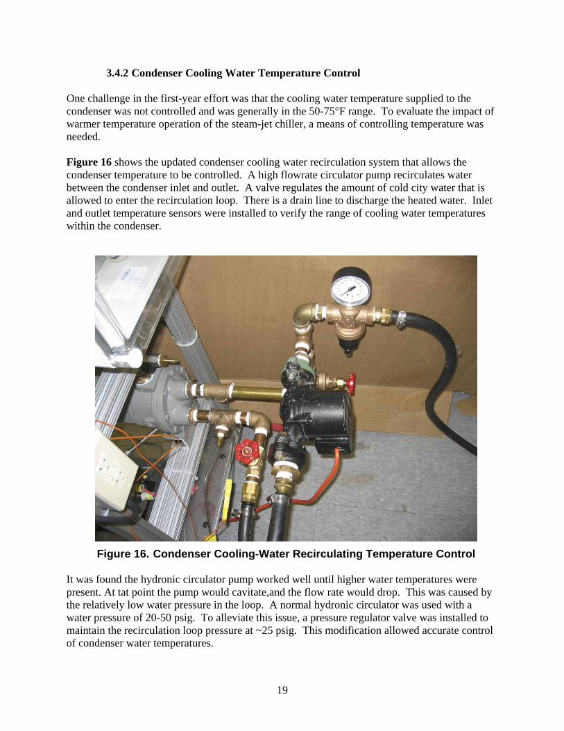
3.4.2 Condenser Cooling Water Temperature Control One challenge in the first-year effort was that the cooling water temperature supplied to the condenser was not controlled and was generally in the 50-75°F range. To evaluate the impact of warmer temperature operation of the steam-jet chiller, a means of controlling temperature was needed. Figure 16 shows the updated condenser cooling water recirculation system that allows the condenser temperature to be controlled. A high flowrate circulator pump recirculates water between the condenser inlet and outlet. A valve regulates the amount of cold city water that is allowed to enter the recirculation loop. There is a drain line to discharge the heated water. Inlet and outlet temperature sensors were installed to verify the range of cooling water temperatures within the condenser.
It was found the hydronic circulator pump worked well until higher water temperatures were present. At tat point the pump would cavitate,and the flow rate would drop. This was caused by the relatively low water pressure in the loop. A normal hydronic circulator was used with a water pressure of 20-50 psig. To alleviate this issue, a pressure regulator valve was installed to maintain the recirculation loop pressure at ~25 psig. This modification allowed accurate control of condenser water temperatures.
Figure 16. Condenser Cooling-Water Recirculating Temperature Control
20
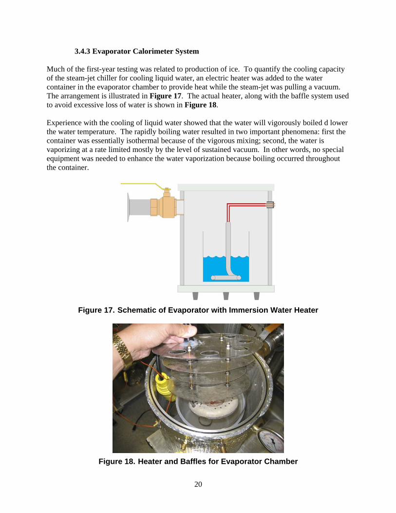
3.4.3 Evaporator Calorimeter System Much of the first-year testing was related to production of ice. To quantify the cooling capacity of the steam-jet chiller for cooling liquid water, an electric heater was added to the water container in the evaporator chamber to provide heat while the steam-jet was pulling a vacuum. The arrangement is illustrated in Figure 17. The actual heater, along with the baffle system used to avoid excessive loss of water is shown in Figure 18. Experience with the cooling of liquid water showed that the water will vigorously boiled d lower the water temperature. The rapidly boiling water resulted in two important phenomena: first the container was essentially isothermal because of the vigorous mixing; second, the water is vaporizing at a rate limited mostly by the level of sustained vacuum. In other words, no special equipment was needed to enhance the water vaporization because boiling occurred throughout the container.
Figure 17. Schematic of Evaporator with Immersion Water Heater
Figure 18. Heater and Baffles for Evaporator Chamber
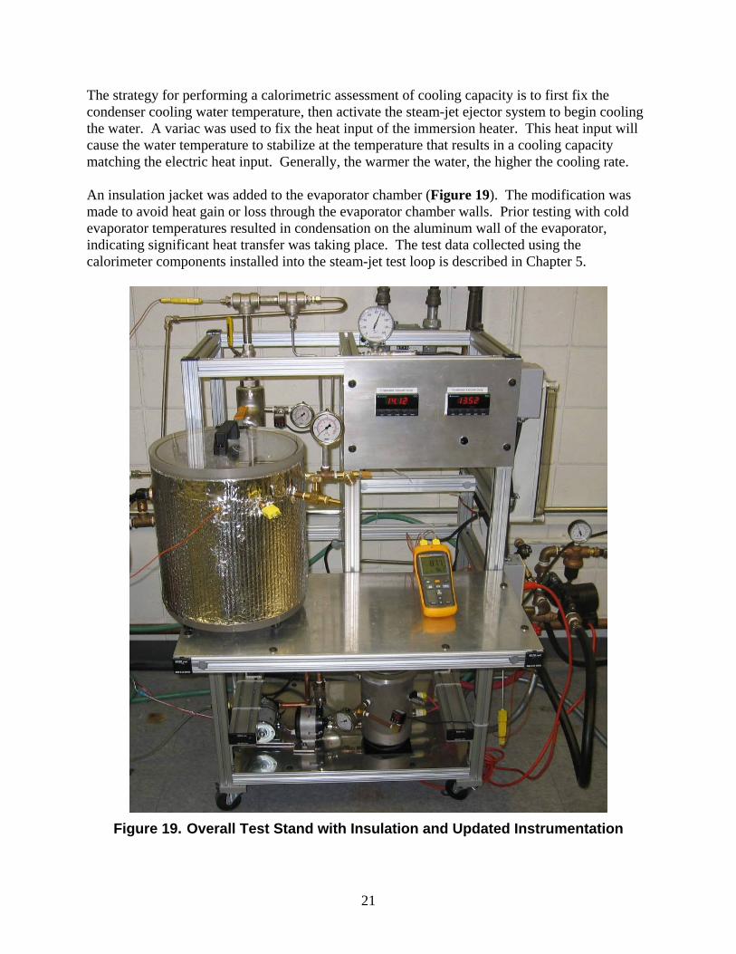
21
The strategy for performing a calorimetric assessment of cooling capacity is to first fix the condenser cooling water temperature, then activate the steam-jet ejector system to begin cooling the water. A variac was used to fix the heat input of the immersion heater. This heat input will cause the water temperature to stabilize at the temperature that results in a cooling capacity matching the electric heat input. Generally, the warmer the water, the higher the cooling rate. An insulation jacket was added to the evaporator chamber (Figure 19). The modification was made to avoid heat gain or loss through the evaporator chamber walls. Prior testing with cold evaporator temperatures resulted in condensation on the aluminum wall of the evaporator, indicating significant heat transfer was taking place. The test data collected using the calorimeter components installed into the steam-jet test loop is described in Chapter 5.
Figure 19. Overall Test Stand with Insulation and Updated Instrumentation
22
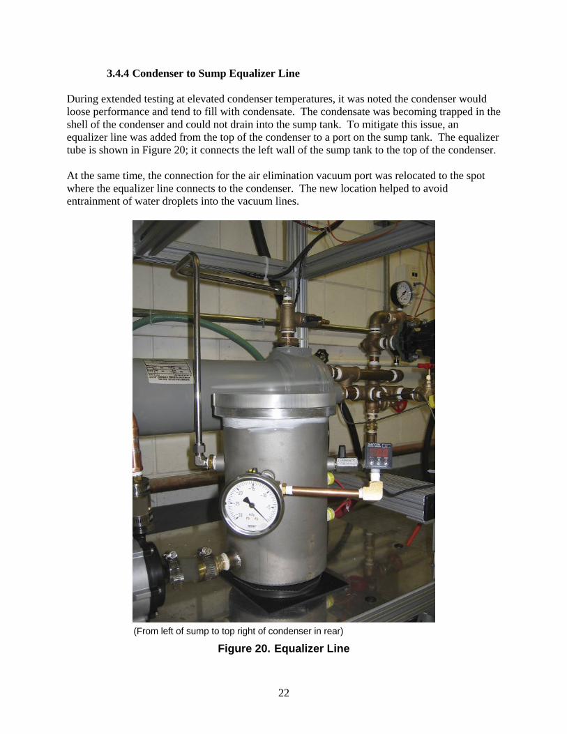
3.4.4 Condenser to Sump Equalizer Line During extended testing at elevated condenser temperatures, it was noted the condenser would loose performance and tend to fill with condensate. The condensate was becoming trapped in the shell of the condenser and could not drain into the sump tank. To mitigate this issue, an equalizer line was added from the top of the condenser to a port on the sump tank. The equalizer tube is shown in Figure 20; it connects the left wall of the sump tank to the top of the condenser. At the same time, the connection for the air elimination vacuum port was relocated to the spot where the equalizer line connects to the condenser. The new location helped to avoid entrainment of water droplets into the vacuum lines.
(From left of sump to top right of condenser in rear)
Figure 20. Equalizer Line
23
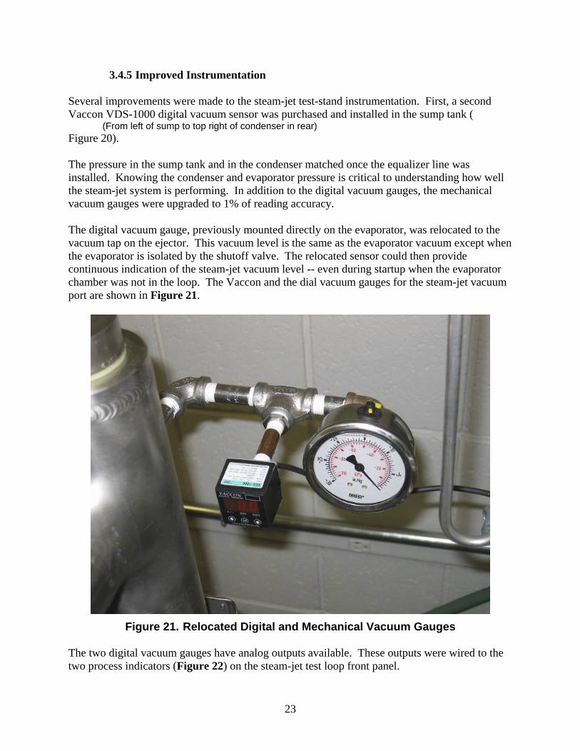
3.4.5 Improved Instrumentation Several improvements were made to the steam-jet test-stand instrumentation. First, a second Vaccon VDS-1000 digital vacuum sensor was purchased and installed in the sump tank ( (From left of sump to top right of condenser in rear) Figure 20). The pressure in the sump tank and in the condenser matched once the equalizer line was installed. Knowing the condenser and evaporator pressure is critical to understanding how well the steam-jet system is performing. In addition to the digital vacuum gauges, the mechanical vacuum gauges were upgraded to 1% of reading accuracy. The digital vacuum gauge, previously mounted directly on the evaporator, was relocated to the vacuum tap on the ejector. This vacuum level is the same as the evaporator vacuum except when the evaporator is isolated by the shutoff valve. The relocated sensor could then provide continuous indication of the steam-jet vacuum level -- even during startup when the evaporator chamber was not in the loop. The Vaccon and the dial vacuum gauges for the steam-jet vacuum port are shown in Figure 21.
Figure 21. Relocated Digital and Mechanical Vacuum Gauges
The two digital vacuum gauges have analog outputs available. These outputs were wired to the two process indicators (Figure 22) on the steam-jet test loop front panel.

24
Figure 22. Vacuum Indicators

25
4. Evaporator Concept Testing One of the key challenges to generating significant cooling capacity from a steam-jet chiller system is in presenting a large amount of water surface area to the vacuum. If this area is restricted, then the cooling rate will also be limited. Ideally, sufficient surface area is available to eliminate this potential degradation in performance. Several concepts were evaluated during the fourth quarter of this program to enhance exposure of water in the evaporator to the vacuum.
4.1 Open Container (Baseline) As a reference case, water was evaporated from a calibrated open container within the chamber. Testing began with the water at room temperature prior to vacuum application. When the steam-jet generated a vacuum, immediate vigorous boiling occurred, with significant splashing of water out of the container. Temperatures dropped quickly to 32°F, and freezing occurred. Despite the splashing, ice formed on the surface of the water. Because the ice created a barrier between the vacuum and the remaining liquid, subsequent temperature drops were considerably slower. This surface ice tended to form in a disk shaped wafer (Figure 23), often with voids between the layers of ice.
Figure 23. Surface Ice Water
26
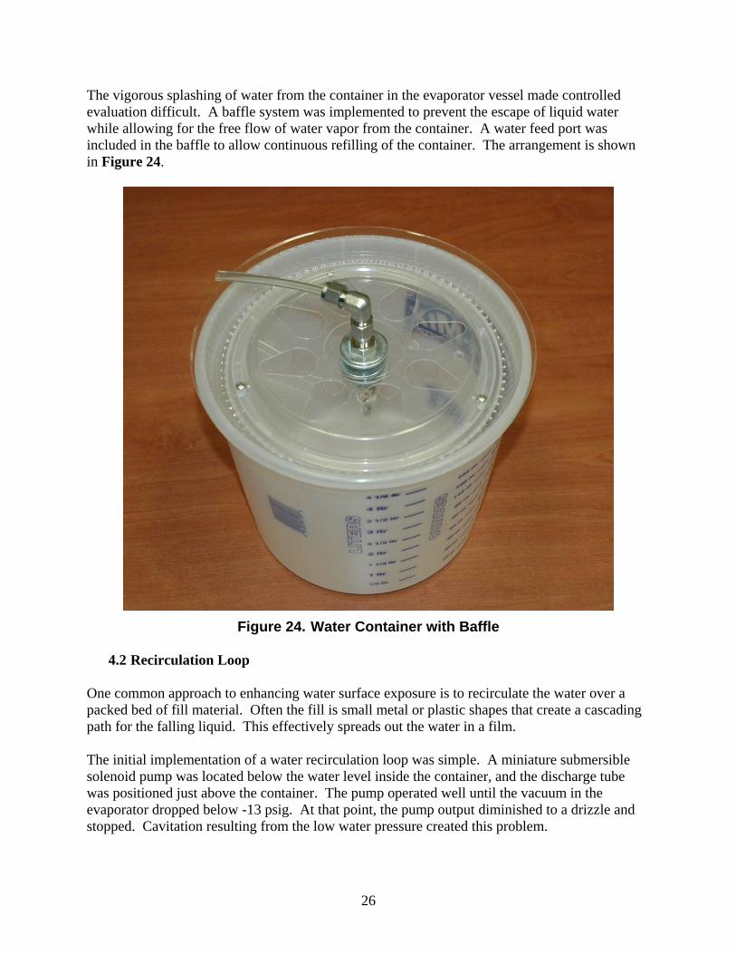
The vigorous splashing of water from the container in the evaporator vessel made controlled evaluation difficult. A baffle system was implemented to prevent the escape of liquid water while allowing for the free flow of water vapor from the container. A water feed port was included in the baffle to allow continuous refilling of the container. The arrangement is shown in Figure 24.
Figure 24. Water Container with Baffle
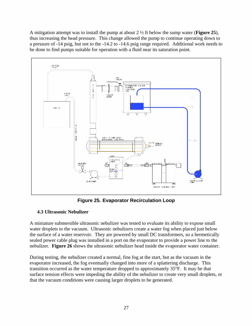
4.2 Recirculation Loop One common approach to enhancing water surface exposure is to recirculate the water over a packed bed of fill material. Often the fill is small metal or plastic shapes that create a cascading path for the falling liquid. This effectively spreads out the water in a film. The initial implementation of a water recirculation loop was simple. A miniature submersible solenoid pump was located below the water level inside the container, and the discharge tube was positioned just above the container. The pump operated well until the vacuum in the evaporator dropped below -13 psig. At that point, the pump output diminished to a drizzle and stopped. Cavitation resulting from the low water pressure created this problem.
27
A mitigation attempt was to install the pump at about 2 ½ ft below the sump water (Figure 25), thus increasing the head pressure. This change allowed the pump to continue operating down to a pressure of -14 psig, but not to the -14.2 to -14.6 psig range required. Additional work needs to be done to find pumps suitable for operation with a fluid near its saturation point.
Figure 25. Evaporator Recirculation Loop
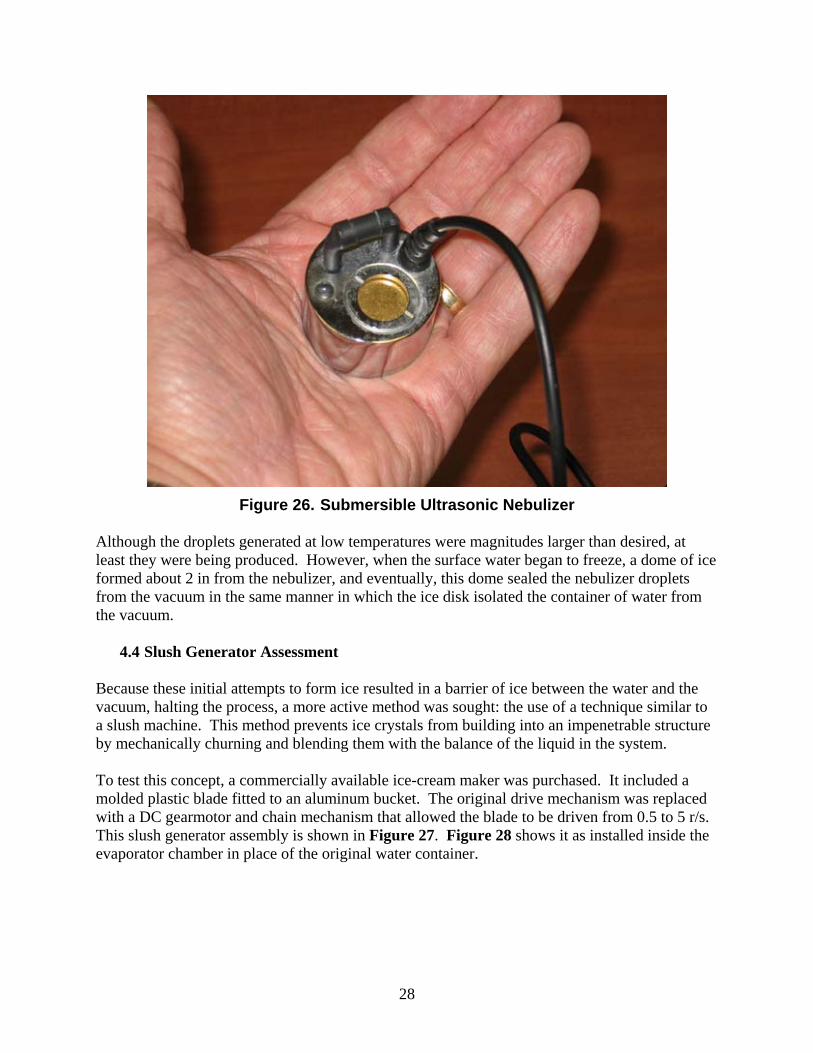
4.3 Ultrasonic Nebulizer A miniature submersible ultrasonic nebulizer was tested to evaluate its ability to expose small water droplets to the vacuum. Ultrasonic nebulizers create a water fog when placed just below the surface of a water reservoir. They are powered by small DC transformers, so a hermetically sealed power cable plug was installed in a port on the evaporator to provide a power line to the nebulizer. Figure 26 shows the ultrasonic nebulizer head inside the evaporator water container. During testing, the nebulizer created a normal, fine fog at the start, but as the vacuum in the evaporator increased, the fog eventually changed into more of a splattering discharge. This transition occurred as the water temperature dropped to approximately 35°F. It may be that surface tension effects were impeding the ability of the nebulizer to create very small droplets, or that the vacuum conditions were causing larger droplets to be generated.
28
Figure 26. Submersible Ultrasonic Nebulizer
Although the droplets generated at low temperatures were magnitudes larger than desired, at least they were being produced. However, when the surface water began to freeze, a dome of ice formed about 2 in from the nebulizer, and eventually, this dome sealed the nebulizer droplets from the vacuum in the same manner in which the ice disk isolated the container of water from the vacuum.
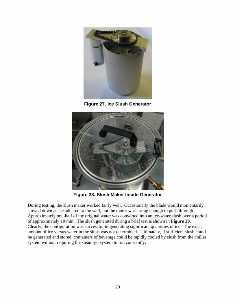
4.4 Slush Generator Assessment Because these initial attempts to form ice resulted in a barrier of ice between the water and the vacuum, halting the process, a more active method was sought: the use of a technique similar to a slush machine. This method prevents ice crystals from building into an impenetrable structure by mechanically churning and blending them with the balance of the liquid in the system. To test this concept, a commercially available ice-cream maker was purchased. It included a molded plastic blade fitted to an aluminum bucket. The original drive mechanism was replaced with a DC gearmotor and chain mechanism that allowed the blade to be driven from 0.5 to 5 r/s. This slush generator assembly is shown in Figure 27. Figure 28 shows it as installed inside the evaporator chamber in place of the original water container.
29
Figure 27. Ice Slush Generator
Figure 28. Slush Maker Inside Generator
During testing, the slush maker worked fairly well. Occasionally the blade would momentarily slowed down as ice adhered to the wall, but the motor was strong enough to push through. Approximately one-half of the original water was converted into an ice-water slush over a period of approximately 10 min. The slush generated during a brief test is shown in Figure 29. Clearly, the configuration was successful in generating significant quantities of ice. The exact amount of ice versus water in the slush was not determined. Ultimately, if sufficient slush could be generated and stored, containers of beverage could be rapidly cooled by slush from the chiller system without requiring the steam-jet system to run constantly.

30
Figure 29. Slush Produced During Testing
section break (even)
31
5. Steam-Jet Refrigeration System Test Program and Results During this effort, several key aspects of the steam-jet refrigeration system were tested. These included the performance of the custom Fox Valve ejector over a range of condenser water temperatures and the operation of this ejector with low pressure (25 psig) steam. The changes made to the test platform allowed accurate measurements of the system performance. The testing also allowed the addition of up to 1 kW (3,412 Btu/h) of electric heat to the evaporator.
5.1 Elevated-Temperature Condenser Testing The Fox ejector used in the test system is designed to provide a vacuum of 0.18 in-Hg -- low enough to produce ice. The design ejector discharge pressure is 1.80 in-Hg, which corresponds to a condenser saturation temperature of about 95°F. All prior testing had been conducted with much cooler city water in the condenser. In the next set of tests, operation of the condenser with water ranging from 66°F up to 128°F was possible. During initial testing, the evaporator and condenser vacuum pressures were calibrated to the saturation curve of water. This test was performed by allowing the system to come to equilibrium, then recording the temperatures and pressures. This is the equivalent of checking the calibration of a thermocouple by immersing it in boiling water, except that the temperature is used to determine the correct saturation pressure. In addition to the vacuum pressure calibration, the local barometric pressure was also monitored. The measured vacuum pressure was subtracted from the barometric pressure to obtain the absolute pressure. By using this technique, evaporator and condenser absolute pressures from 14.7 psia (atmospheric pressure) down to about 0.1 psia can be measured with an accuracy of about +/- 0.05 psia. Except for the very lowest evaporator pressures, this yields acceptable accuracies.
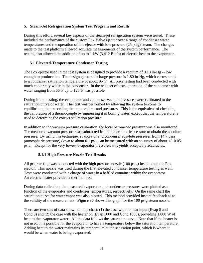
5.1.1 High-Pressure Nozzle Test Results All prior testing was conducted with the high pressure nozzle (100 psig) installed on the Fox ejector. This nozzle was used during the first elevated condenser temperature testing as well. Tests were conducted with a charge of water in a baffled container within the evaporator. An electric heater provided a thermal load. During data collection, the measured evaporator and condenser pressures were plotted as a function of the evaporator and condenser temperatures, respectively. On the same chart the saturation curve for water vapor was also plotted. This method provided instant feedback as to the validity of the measurement. Figure 30 shows this graph for the 100 psig steam nozzle. There are two sets of data shown on this chart: (1) the case with no heat input (Evap 0 and Cond 0) and (2) the case with the heater on (Evap 1000 and Cond 1000), providing 1,000 W of heat to the evaporator water. All the data follows the saturation curve. Note that if the heater is not used, it is possible for the evaporator to have a temperature below the saturation temperature. Adding heat to the water maintains its temperature at the saturation point, which is where it would be when water is being evaporated.
32
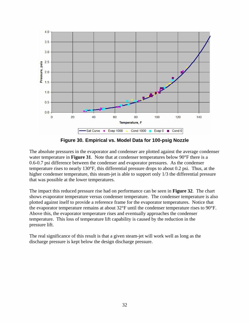
Figure 30. Empirical vs. Model Data for 100-psig Nozzle The absolute pressures in the evaporator and condenser are plotted against the average condenser water temperature in Figure 31. Note that at condenser temperatures below 90°F there is a 0.6-0.7 psi difference between the condenser and evaporator pressures. As the condenser temperature rises to nearly 130°F, this differential pressure drops to about 0.2 psi. Thus, at the higher condenser temperature, this steam-jet is able to support only 1/3 the differential pressure that was possible at the lower temperatures. The impact this reduced pressure rise had on performance can be seen in Figure 32. The chart shows evaporator temperature versus condenser temperature. The condenser temperature is also plotted against itself to provide a reference frame for the evaporator temperatures. Notice that the evaporator temperature remains at about 32°F until the condenser temperature rises to 90°F. Above this, the evaporator temperature rises and eventually approaches the condenser temperature. This loss of temperature lift capability is caused by the reduction in the pressure lift. The real significance of this result is that a given steam-jet will work well as long as the discharge pressure is kept below the design discharge pressure.

33
Figure 31. Evaporator and Condenser Pressures for 100-psig Nozzle
Figure 32. Evaporator and Condenser Temperatures for 100-psig Nozzle
34
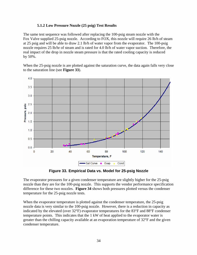
5.1.2 Low Pressure Nozzle (25 psig) Test Results The same test sequence was followed after replacing the 100-psig steam nozzle with the Fox Valve supplied 25-psig nozzle. According to FOX, this nozzle will require 26 lb/h of steam at 25 psig and will be able to draw 2.1 lb/h of water vapor from the evaporator. The 100-psig nozzle requires 25 lb/hr of steam and is rated for 4.0 lb/h of water vapor suction. Therefore, the real impact of the drop in nozzle steam pressure is that the rated cooling capacity is reduced by 50%. When the 25-psig nozzle is are plotted against the saturation curve, the data again falls very close to the saturation line (see Figure 33).
Figure 33. Empirical Data vs. Model for 25-psig Nozzle
The evaporator pressures for a given condenser temperature are slightly higher for the 25-psig nozzle than they are for the 100-psig nozzle. This supports the vendor performance specification difference for these two nozzles. Figure 34 shows both pressures plotted versus the condenser temperature for the 25-psig nozzle tests. When the evaporator temperature is plotted against the condenser temperature, the 25-psig nozzle data is very similar to the 100-psig nozzle. However, there is a reduction in capacity as indicated by the elevated (over 32°F) evaporator temperatures for the 83°F and 88°F condenser temperature points. This indicates that the 1 kW of heat applied to the evaporator water is greater than the chilling capacity available at an evaporation temperature of 32°F and the given condenser temperature.
35
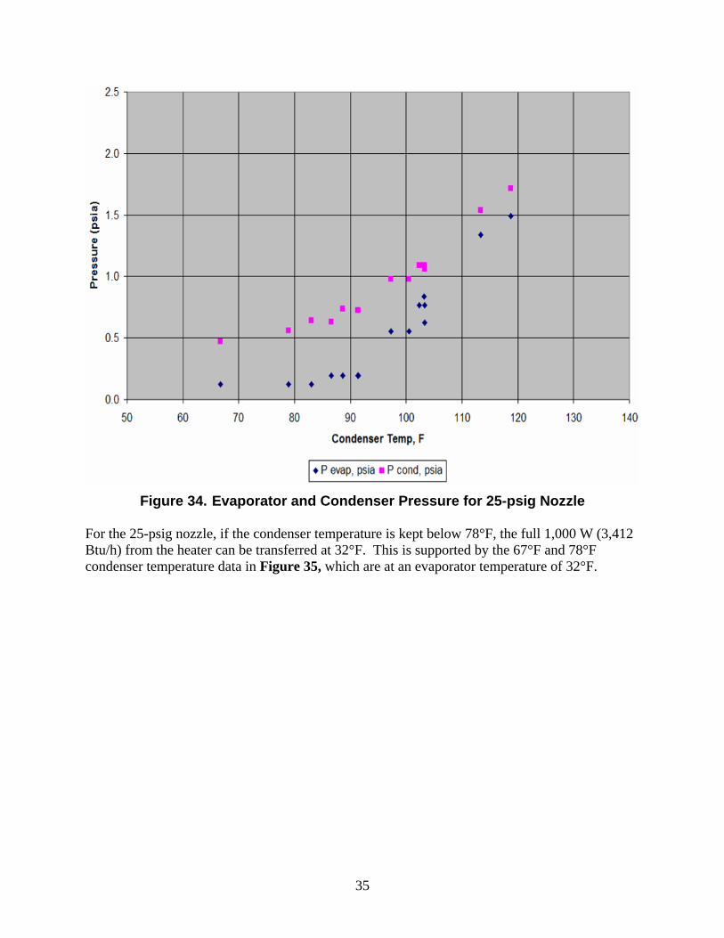
Figure 34. Evaporator and Condenser Pressure for 25-psig Nozzle
For the 25-psig nozzle, if the condenser temperature is kept below 78°F, the full 1,000 W (3,412 Btu/h) from the heater can be transferred at 32°F. This is supported by the 67°F and 78°F condenser temperature data in Figure 35, which are at an evaporator temperature of 32°F.
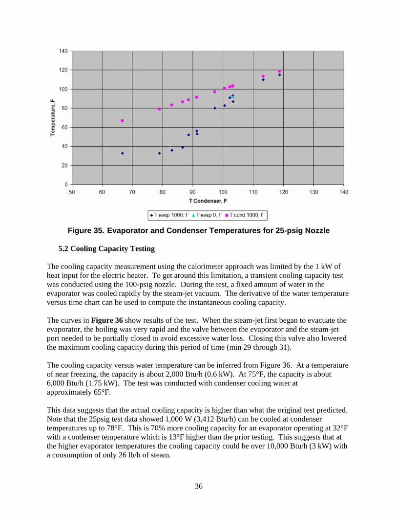
36
Figure 35. Evaporator and Condenser Temperatures for 25-psig Nozzle
5.2 Cooling Capacity Testing The cooling capacity measurement using the calorimeter approach was limited by the 1 kW of heat input for the electric heater. To get around this limitation, a transient cooling capacity test was conducted using the 100-psig nozzle. During the test, a fixed amount of water in the evaporator was cooled rapidly by the steam-jet vacuum. The derivative of the water temperature versus time chart can be used to compute the instantaneous cooling capacity. The curves in Figure 36 show results of the test. When the steam-jet first began to evacuate the evaporator, the boiling was very rapid and the valve between the evaporator and the steam-jet port needed to be partially closed to avoid excessive water loss. Closing this valve also lowered the maximum cooling capacity during this period of time (min 29 through 31). The cooling capacity versus water temperature can be inferred from Figure 36. At a temperature of near freezing, the capacity is about 2,000 Btu/h (0.6 kW). At 75°F, the capacity is about 6,000 Btu/h (1.75 kW). The test was conducted with condenser cooling water at approximately 65°F. This data suggests that the actual cooling capacity is higher than what the original test predicted. Note that the 25psig test data showed 1,000 W (3,412 Btu/h) can be cooled at condenser temperatures up to 78°F. This is 70% more cooling capacity for an evaporator operating at 32°F with a condenser temperature which is 13°F higher than the prior testing. This suggests that at the higher evaporator temperatures the cooling capacity could be over 10,000 Btu/h (3 kW) with a consumption of only 26 lb/h of steam.
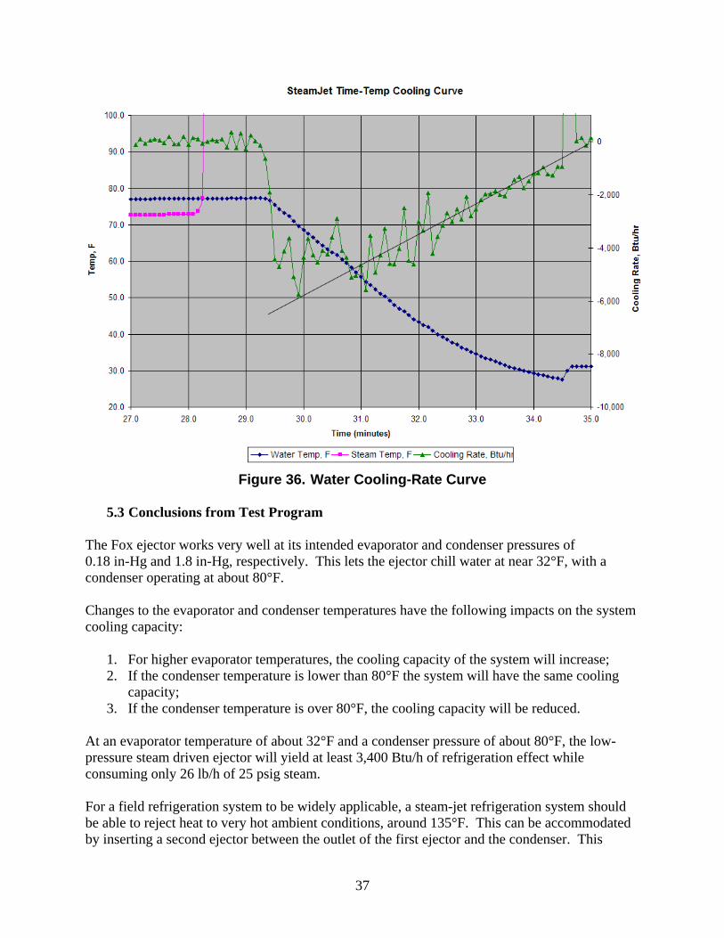
37
Figure 36. Water Cooling-Rate Curve
5.3 Conclusions from Test Program The Fox ejector works very well at its intended evaporator and condenser pressures of 0.18 in-Hg and 1.8 in-Hg, respectively. This lets the ejector chill water at near 32°F, with a condenser operating at about 80°F. Changes to the evaporator and condenser temperatures have the following impacts on the system cooling capacity:
1. For higher evaporator temperatures, the cooling capacity of the system will increase; 2. If the condenser temperature is lower than 80°F the system will have the same cooling
capacity; 3. If the condenser temperature is over 80°F, the cooling capacity will be reduced.
At an evaporator temperature of about 32°F and a condenser pressure of about 80°F, the low-pressure steam driven ejector will yield at least 3,400 Btu/h of refrigeration effect while consuming only 26 lb/h of 25 psig steam. For a field refrigeration system to be widely applicable, a steam-jet refrigeration system should be able to reject heat to very hot ambient conditions, around 135°F. This can be accommodated by inserting a second ejector between the outlet of the first ejector and the condenser. This
38
second ejector will raise the pressure of the steam entering the condenser from about 1 in-Hg up to 3 in-Hg, and the condenser temperature to just over 140°F. Although the second ejector will consume additional steam, it will not require any further complications to the fairly straightforward cooling system. The exact steam consumption and sizing of the second ejector are currently being solicited from Fox Valve.
section break (even)
39
6. Cold Storage Approach Analysis The results of both the evaporator concept testing and the Steam-Jet Refrigeration System Test Program demonstrated that a steam-jet chiller system will be able to provide cooling to a load when the kitchen is in use and there is a supply of waste steam available. Three techniques were investigated during this project to enable this intermittent cooling capability to provide a cold storage capability: (1) cooling the water directly and storing it, (2) freezing water into ice and (3) freezing an intermediate phase change material (PCM). The first two techniques were assessed during the concept testing, as discussed in Chapter 4: The third was assessed later in the project. The analyses of the three techniques are discussed in Sections 6.1, 6.2, and 6.3, respectively. Section 6.4 discusses the conclusions from the analyses. The analysis assumes that potable water is available at 100°F for cooling down to 40°F. The total amount of chilled water to be supplied is assumed to be 32 gal/d. This capacity will provide about 500 eight-oz servings of cold water per day.
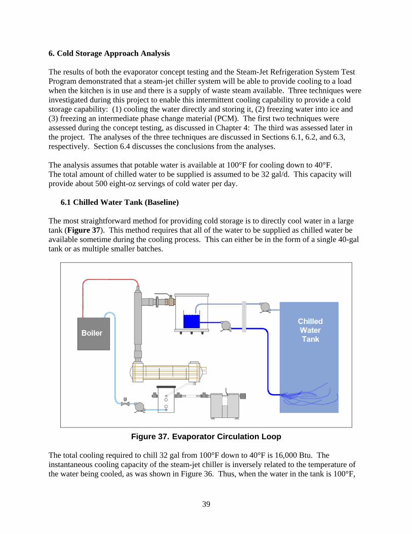
6.1 Chilled Water Tank (Baseline) The most straightforward method for providing cold storage is to directly cool water in a large tank (Figure 37). This method requires that all of the water to be supplied as chilled water be available sometime during the cooling process. This can either be in the form of a single 40-gal tank or as multiple smaller batches.
Figure 37. Evaporator Circulation Loop
The total cooling required to chill 32 gal from 100°F down to 40°F is 16,000 Btu. The instantaneous cooling capacity of the steam-jet chiller is inversely related to the temperature of the water being cooled, as was shown in Figure 36. Thus, when the water in the tank is 100°F,
40
the cooling capacity may be considerably higher than 6,000 Btu/h. This cooling rate will drop to about 3,000 Btu/h at 40°F if the condenser water is kept at 65°F. Further testing will need to be conducted to evaluate the performance for warmer condenser cooling water temperatures. A spreadsheet was used to calculate the cooling of a 32-gal tank of water with this variable cooling rate. The results of the assessment are shown in Figure 38. The tank can be cooled to 40°F in just over 3 hours. A similar assessment shows that a 40-gal tank can be cooled in less than 4 h. Thus, the cooling capability of the steam-jet cooling system appears to be consistent with the requirements of a field kitchen.
0
10
20
30
40
50
60
70
80
90
100
0.0 0.5 1.0 1.5 2.0 2.5 3.0 3.5 4.0 4.5 5.0
Time, hrs
Wa
ter
Te
mp
era
ture
, F
0
1,000
2,000
3,000
4,000
5,000
6,000
7,000
8,000
9,000
Co
oli
ng
Ra
te,
Btu
/hr
Figure 38. Cooling Rate Curve for a 32-Gal Tank
Storing the "cold" directly in the water to be supplied has significant advantage in that the average cooling rate starts at 7,800 Btu/h (at 100°F) and gradually drops to 2,900 Btu/hr (at 40°F), with an average cooling rate of about 5,100 Btu/h. The storage size and weight for the direct cooling approach is simply the size and weight of 32 gal of water (265 lb and 4.25 ft³).
41
6.2 Ice and Slush During the first year effort, ice was successfully produced using the steam-jet system. Two main difficulties in producing ice were addressed. The first issue was that when ice forms on a free water surface, it creates a barrier to continued evaporation of the remaining water. The second problem is that the water is both the constituent being frozen, as well as the fluid being circulated, and when water freezes it cannot easily be pumped. As discussed in Section 4.4, one technique used to avoid both the evaporation barrier and pumping problems was to create a slurry of ice slush rather than a solid block of ice. This slush generator assembly was shown in Figure 27. During testing, the slush maker worked well, so work began on evaluating the process from the standpoint of cooling capacity, the metrics required for storing the cold in the form of ice, and how a system could be configured. Figure 39 shows one potential configuration. If a slush/ice mixture is stored in an insulated tank and water for beverages is circulated through this bath, a heat exchanger is necessary to prevent the sump water from contaminating the beverage water. The beverage could be circulated as formulated, or the water could be circulated prior to blending with the beverage mix. As with the case of directly cooling a tank of water, the slush-ice cold storage system will need to cool 32 gal by 60°F -- this will require 16,000 Btu of cooling. If the ice is ultimately stored as a 50/50 mix of ice and cold water, the cooling capacity per pound of slush will be about 80 Btu/lb, assuming all the slush is eventually melted and then heated to 40°F.
Figure 39. Ice-Slush Cold Storage System Layout The theoretical weight of slush mixture needed for this amount of cold storage is 200 lb. The volume needed will be 3.2 ft³ for the slush and about 0.5 ft³ for the potable water heat exchanger -- a total tank volume of 3.7 ft³. In addition to the slush tank, the 32 gallons of water to be cooled will need to be supplied in external tanks. Thus, the tank volume for slush storage is only about 15% smaller than for the cold water storage tank approach.

42
The time needed to provide the full 16,000 Btu of cooling capacity will again depend on the temperature of the water during the cooling process. If the water to be converted to slush begins at 100°F, the total amount of cooling needed from the steam-jet will be more than that needed to cool the beverage. If the 200 lb of 100°F water must be cooled by 68°F to drop the temperature to freezing, half this water must be frozen. This amounts to 28,000 Btu of cooling.
where Q = 28,000 Btu
M = 200 lb Cp = 1 Btu/lb*F dT = 68F hig = 144 Btu/lb
During the cool-down process, the water will have an average temperature of 66°F and the average cooling rate will be about 5,000 Btu/hr. The quantity of cooling for this process is 13,600 Btu and will take 2.7 h. The remaining cooling (14,400 Btu) freezes half the water to ice. Because this cooling takes place at 32°F, the cooling capacity is only 2,350 Btu/hr (from Figure 36) and will take 6.1 h to complete; therefore, the total cooling time will be 8.8 hr. This is nearly 6 h longer than the direct water cooling strategy.
6.3 Non-Water-Based Phase-Change Material It would be desirable to use a phase-change material that would absorb heat at a temperature slightly above the freezing point of water. This would avoid the previously discussed problem of freezing the working fluid. PCMs are available over a wide range of phase-change temperatures (see Figure 40). Although the heat of fusion for the A4 PCM listed is about 35% less than for water-ice, the entire volume of the PCM can be frozen because liquid water can still be used as a heat transfer medium. The total weight of A4 PCM needed to cool 32 gal of water from 100°F to 40°F is 163 lb, with a PCM volume of 3.4 ft³. Of course, this volume would need room for containers separating the PCM from the working fluid and provide sufficient heat transfer area. A realistic total PCM tank volume would be just under 4 ft³. The cooling requirements for the steam-jet to cool the PCM tank from 100°F down to the freezing point of 39°F will be 21,000 Btu. About 25% of this is due to the sensible cooling of the materials; 75% is due to the PCM latent heat. The cool-down process would require about 6.4 hours of cooling at 39°F to fully freeze the PCM.
Q = M*(Cp*dT+0.5*hig) ( 24 )
43
Figure 40. PCM Properties of EPS Ltd. Products
44
Although the PCM approach significantly mitigates the problems associated with freezing the working fluid, it still has one important issue; it transfers most of the cooling at the minimum temperature when the cooling capacity of the steam-jet is at a minimum. This tends to extend the required cool down times. Fortunately, the direct water chilling technique is able to provide high cooling rates in a relatively compact tank.
6.4 Preferred Approach: Chilled Water Tank The conclusion was that producing and storing chilled water is significantly better -- from both a capacity and size standpoint -- than attempting to utilize ice or phase-change materials. The most straightforward method for generating the chilled water is to pass the steam-jet chilled water through a small heat exchanger, as shown in Figure 41. This allows the stored water to be at atmospheric pressure while the steam-jet water is at a pressure of a few psia. Water from an insulated storage tank is passed through the heat exchanger and recirculated within the storage tank.
Figure 41. Evaporator Recirculation Loop
The total cooling required to bring 95 gal from 100°F down to 40°F is 47,000 Btu. The instantaneous cooling capacity of the steam-jet chiller is inversely related to the temperature of the water being cooled, as was shown in Figure 36. If the higher cooling rates identified during the testing hold over the full range of cooling temperatures, the 95 gal of water can be cooled from 100°F to 40°F in just over 5 h. Of course, the test platform is only consuming 26 lb/h of "waste" low-pressure steam. If the steam supply was increased to 100 lb/h, and the hardware appropriately resized, it may be possible to cool this quantity of water in less than 1 ½ h. Therefore, the cooling capability of the steam-jet cooling system appears to be consistent with the requirements of the field kitchen application.
section break (even)

45
7. Conclusions The efforts conducted during this BAA program provide a solid theoretical and experimental basis for development of practical field refrigeration equipment utilizing steam-jet refrigeration. Regardless of the specific configuration eventually selected, a successful demonstration unit will show that significant cooling capacity can be delivered in the field with a quietly operating JP-8-fired system. The significantly higher cooling capacities will open up a wide variety of potential field applications.
46
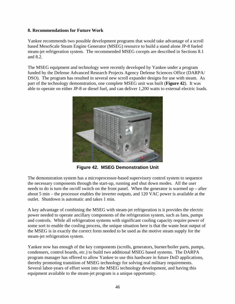
8. Recommendations for Future Work Yankee recommends two possible development programs that would take advantage of a scroll based MesoScale Steam Engine Generator (MSEG) resource to build a stand alone JP-8 fueled steam-jet refrigeration system. The recommended MSEG cocepts are described in Sections 8.1 and 8.2. The MSEG equipment and technology were recently developed by Yankee under a program funded by the Defense Advanced Research Projects Agency Defense Sciences Office (DARPA/ DSO). The program has resulted in several new scroll expander designs for use with steam. As part of the technology demonstration, one complete MSEG unit was built (Figure 42). It was able to operate on either JP-8 or diesel fuel, and can deliver 1,200 watts to external electric loads.
Figure 42. MSEG Demonstration Unit The demonstration system has a microprocessor-based supervisory control system to sequence the necessary components through the start-up, running and shut down modes. All the user needs to do is turn the on/off switch on the front panel. When the generator is warmed up – after about 5 min – the processor enables the inverter outputs, and 120 VAC power is available at the outlet. Shutdown is automatic and takes 1 min. A key advantage of combining the MSEG with steam-jet refrigeration is it provides the electric power needed to operate ancillary components of the refrigeration system, such as fans, pumps and controls. While all refrigeration systems with significant cooling capacity require power of some sort to enable the cooling process, the unique situation here is that the waste heat output of the MSEG is in exactly the correct form needed to be used as the motive steam supply for the steam-jet refrigeration system. Yankee now has enough of the key components (scrolls, generators, burner/boiler parts, pumps, condensers, control boards, etc.) to build two additional MSEG based systems. The DARPA program manager has offered to allow Yankee to use this hardware in future DoD applications, thereby promoting transition of MSEG technology for solving real military requirements. Several labor-years of effort went into the MSEG technology development, and having this equipment available to the steam-jet program is a unique opportunity.
47
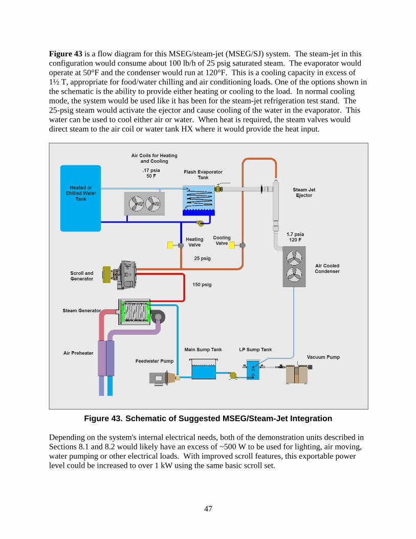
Figure 43 is a flow diagram for this MSEG/steam-jet (MSEG/SJ) system. The steam-jet in this configuration would consume about 100 lb/h of 25 psig saturated steam. The evaporator would operate at 50°F and the condenser would run at 120°F. This is a cooling capacity in excess of 1½ T, appropriate for food/water chilling and air conditioning loads. One of the options shown in the schematic is the ability to provide either heating or cooling to the load. In normal cooling mode, the system would be used like it has been for the steam-jet refrigeration test stand. The 25-psig steam would activate the ejector and cause cooling of the water in the evaporator. This water can be used to cool either air or water. When heat is required, the steam valves would direct steam to the air coil or water tank HX where it would provide the heat input.
Figure 43. Schematic of Suggested MSEG/Steam-Jet Integration Depending on the system's internal electrical needs, both of the demonstration units described in Sections 8.1 and 8.2 would likely have an excess of ~500 W to be used for lighting, air moving, water pumping or other electrical loads. With improved scroll features, this exportable power level could be increased to over 1 kW using the same basic scroll set.
48
Clearly, the system can be scaled up or down as needed, provided that the MSEG hardware is still sized appropriately. There is also the option of decoupling the MSEG and steam-jet systems to a degree. For example, the burner could be operated at a higher firing rate than the MSEG requires, and the excess steam could be fed to a larger, or a second, steam-jet. This arrangement could produce ~3 T of refrigeration with sufficient electric power generation to operate the cooling system.
8.1 MSEG Chiller Concept
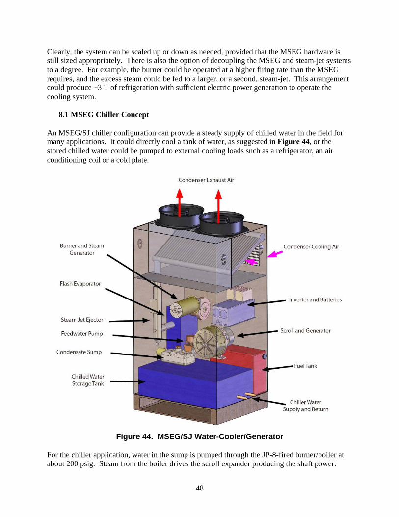
An MSEG/SJ chiller configuration can provide a steady supply of chilled water in the field for many applications. It could directly cool a tank of water, as suggested in Figure 44, or the stored chilled water could be pumped to external cooling loads such as a refrigerator, an air conditioning coil or a cold plate.
Figure 44. MSEG/SJ Water-Cooler/Generator
For the chiller application, water in the sump is pumped through the JP-8-fired burner/boiler at about 200 psig. Steam from the boiler drives the scroll expander producing the shaft power.
49
A six-phase permanent-magnet generator works with a rectifier and the inverter to provide the AC output power. Waste steam from the scroll is delivered to the steam-jet nozzle where it is the motive fluid causing the ejector to pull a vacuum on the flash evaporator. The motive steam, along with the water vapor pulled from the evaporator, is discharged to a direct air cooled condenser. A small vacuum pump, or a two-stage mini-ejector, pulls the non-condensable gases from the condenser. The condensate flows by gravity to a low pressure sump tank (~1.7 psia), as was shown in Figure 43. Periodically, water from the low pressure sump is pumped to the atmospheric pressure sump to maintain proper water levels. The chilled evaporator water is used to cool the water in the storage tank. This can be accomplished by a separate heat exchanger, or by configuring the evaporator such that it directly cools the water tank.
8.2 MSEG Refrigerator Concept If it is desired that the stand alone hardware be able to deliver a stream of cool air to a refrigerator, the MSEG/SJ system can be integrated into an air chilling package. The integrated layout for a cool air delivery system is shown in Figure 45. In this example, the large chilled water tank is not necessary, and the chilled evaporator water is circulated though a set of cooling coils. Air from the refrigerator is forced over the cooling coils and returned to the cabinet.
Figure 45. MSEG/SJ Refrigerator
09 / 023

50
(This page inserted for layout purposes.)
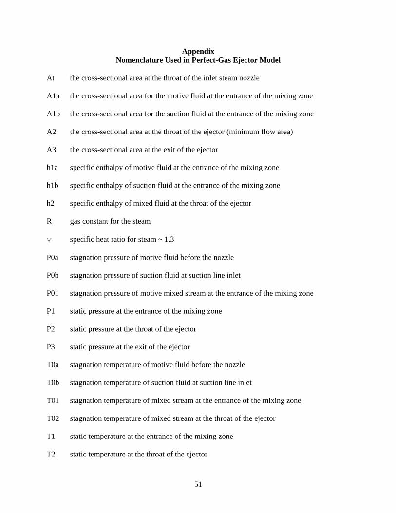
51
Appendix Nomenclature Used in Perfect-Gas Ejector Model
At the cross-sectional area at the throat of the inlet steam nozzle A1a the cross-sectional area for the motive fluid at the entrance of the mixing zone A1b the cross-sectional area for the suction fluid at the entrance of the mixing zone A2 the cross-sectional area at the throat of the ejector (minimum flow area) A3 the cross-sectional area at the exit of the ejector h1a specific enthalpy of motive fluid at the entrance of the mixing zone h1b specific enthalpy of suction fluid at the entrance of the mixing zone h2 specific enthalpy of mixed fluid at the throat of the ejector R gas constant for the steam γ specific heat ratio for steam ~ 1.3 P0a stagnation pressure of motive fluid before the nozzle P0b stagnation pressure of suction fluid at suction line inlet P01 stagnation pressure of motive mixed stream at the entrance of the mixing zone P1 static pressure at the entrance of the mixing zone P2 static pressure at the throat of the ejector P3 static pressure at the exit of the ejector T0a stagnation temperature of motive fluid before the nozzle T0b stagnation temperature of suction fluid at suction line inlet T01 stagnation temperature of mixed stream at the entrance of the mixing zone T02 stagnation temperature of mixed stream at the throat of the ejector T1 static temperature at the entrance of the mixing zone T2 static temperature at the throat of the ejector

52
T3 static temperature at the exit of the ejector C1 speed of sound at the entrance to the mixing zone C2 speed of sound at the throat of the ejector C1* critical speed of sound at the entrance to the mixing zone (speed of sound when fluid is
moving at the speed of sound, M=1) C2* critical speed of sound at the throat of the ejector (speed of sound when fluid is moving at
the speed of sound, M=1) Wa mass flow rate of motive steam Wb mass flow rate of suction water vapor W2 mixed mass flow rate in ejector = Wa + Wb ρ1a density of motive steam at inlet to mixing zone ρ1b density of suction water vapor at inlet to mixing zone ρ2 stagnation density of mixed stream at the ejector throat V2 velocity at throat of ejector
Related Documents