Welcome message from author
This document is posted to help you gain knowledge. Please leave a comment to let me know what you think about it! Share it to your friends and learn new things together.
Transcript
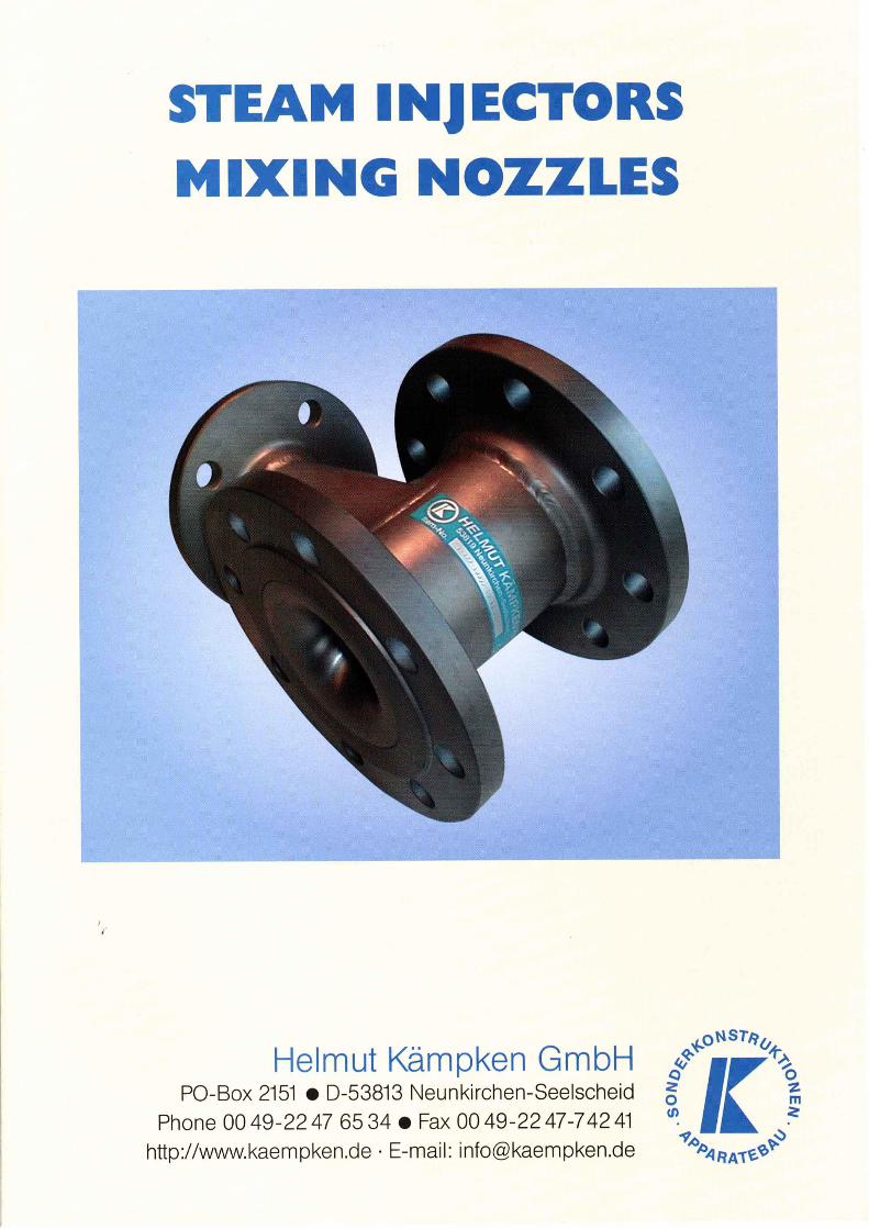

Steam Injector / Steam Lance for Vessel-Mounting Type IFA
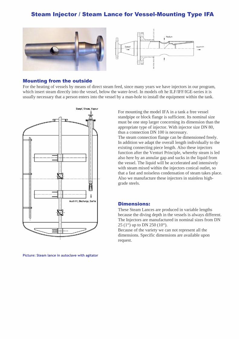
Mounting from the outside For the heating of vessels by means of direct steam feed, since many years we have injectors in our program, which insert steam directly into the vessel, below the water-level. In models oft he ILF/IFF/IGE-series it is usually necessary that a person enters into the vessel by a man-hole to install the equipment within the tank.
For mounting the model IFA in a tank a free vessel standpipe or block flange is sufficient. Its nominal size must be one step larger concerning its dimension than the appropriate type of injector. With injector size DN 80, thus a connection DN 100 is necessary. The steam connection flange can be dimensioned freely. In addition we adapt the overall length individually to the existing connecting piece length. Also these injectors function after the Venturi Principle, whereby steam is led also here by an annular gap and sucks in the liquid from the vessel. The liquid will be accelerated and intensively with steam mixed within the injectors conical outlet, so that a fast and noiseless condensation of steam takes place. Also we manufacture these injectors in stainless high-grade steels.
Dimensions: These Steam Lances are produced in variable lengths because the diving depth in the vessels is always different. The Injectors are manufactured in nominal sizes from DN 25 (1“) up to DN 250 (10“). Because of the variety we can not represent all the dimensions. Specific dimensions are available upon request.
Picture: Steam lance in autoclave with agitator
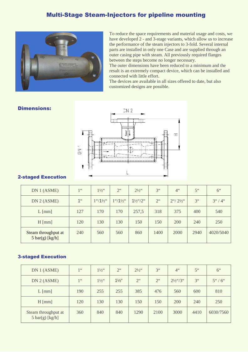
Multi-Stage Steam-Injectors for pipeline mounting
To reduce the space requirements and material usage and costs, we have developed 2 - and 3-stage variants, which allow us to increase the performance of the steam injectors to 3-fold. Several internal parts are installed in only one Case and are supplied through an outer casing pipe with steam. All previously required flanges between the steps become no longer necessary. The outer dimensions have been reduced to a minimum and the result is an extremely compact device, which can be installed and connected with little effort. The devices are available in all sizes offered to date, but also customized designs are possible.
Dimensions:
2-staged Execution
DN 1 (ASME) 1“ 1½“ 2“ 2½“ 3“ 4“ 5“ 6“
DN 2 (ASME) 1“ 1“/1½“ 1“/1½“ 1½“/2“ 2“ 2“/ 2½“ 3“ 3“ / 4“
L [mm] 127 170 170 257,5 318 375 400 540
H [mm] 120 130 130 150 150 200 240 250
Steam throughput at 5 bar(g) [kg/h]
240 560 560 860 1400 2000 2940 4020/5040
3-staged Execution
DN 1 (ASME) 1“ 1½“ 2“ 2½“ 3“ 4“ 5“ 6“
DN 2 (ASME) 1“ 1½“ 1½“ 2“ 2“ 2½“/3“ 3“ 5“ / 6“
L [mm] 190 255 255 385 476 560 600 810
H [mm] 120 130 130 150 150 200 240 250
Steam throughput at 5 bar(g) [kg/h]
360 840 840 1290 2100 3000 4410 6030/7560
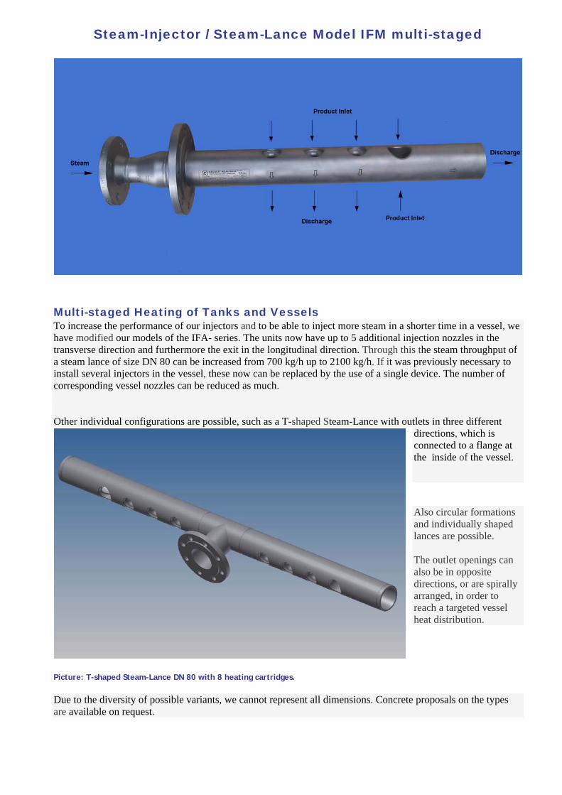
Steam-Injector / Steam-Lance Model IFM multi-staged
Multi-staged Heating of Tanks and Vessels To increase the performance of our injectors and to be able to inject more steam in a shorter time in a vessel, we have modified our models of the IFA- series. The units now have up to 5 additional injection nozzles in the transverse direction and furthermore the exit in the longitudinal direction. Through this the steam throughput of a steam lance of size DN 80 can be increased from 700 kg/h up to 2100 kg/h. If it was previously necessary to install several injectors in the vessel, these now can be replaced by the use of a single device. The number of corresponding vessel nozzles can be reduced as much. Other individual configurations are possible, such as a T-shaped Steam-Lance with outlets in three different
directions, which is connected to a flange at the inside of the vessel.
Also circular formations and individually shaped lances are possible. The outlet openings can also be in opposite directions, or are spirally arranged, in order to reach a targeted vessel heat distribution.
Picture: T-shaped Steam-Lance DN 80 with 8 heating cartridges.
Due to the diversity of possible variants, we cannot represent all dimensions. Concrete proposals on the types are available on request.

Picture.: Steam-Lance with 5 transverse heating stages in opposite direction and 1 in longitudinal direction
Picture.: Steam-Lance 3-staged without longitudinal stage
Picture.: Steam-Lance 3+1 staged
Related Documents