CDM MONITORING REPORT November 27, 2008 Beijing No.3 Thermal Power Plant Gas-Steam Combined Cycle Project Using Natural Gas 1 Beijing No.3 Thermal Power Plant Gas- Steam Combined Cycle Project Using Natural Gas CDM Registration Ref. N. 1373 CDM MONITORING REPORT 1 Monitoring period: 15 February 2008 – 30 June 2008 Project participants: Jingfeng Gas Fired Power Co. Ltd RWE Power AG Monitoring Report prepared by the CDM Consultant: Enecore Carbon Ltd

Welcome message from author
This document is posted to help you gain knowledge. Please leave a comment to let me know what you think about it! Share it to your friends and learn new things together.
Transcript

CDM MONITORING REPORT November 27, 2008 Beijing No.3 Thermal Power Plant Gas-Steam Combined Cycle Project Using Natural Gas
1
Beijing No.3 Thermal Power Plant Gas-Steam Combined Cycle Project Using
Natural Gas
CDM Registration Ref. N. 1373
CDM MONITORING REPORT 1
Monitoring period: 15 February 2008 – 30 June 2008
Project participants:
Jingfeng Gas Fired Power Co. Ltd
RWE Power AG
Monitoring Report prepared by the CDM Consultant:
Enecore Carbon Ltd

CDM MONITORING REPORT November 27, 2008 Beijing No.3 Thermal Power Plant Gas-Steam Combined Cycle Project Using Natural Gas
2
CONTENTS A. General project activity and monitoring information B. Key monitoring activities C. Quality assurance and quality control measures D. Calculation of GHG emission reductions Annexes and Appendixes Annex 1: Definition and acronyms Annex 2: Technical drawing Annex 3: Energy and material flowchart including metering positions Appendix A – Summary of GHG emission reduction during the monitoring period Appendix B – Calculation of GHG emission reduction by the project activity

CDM MONITORING REPORT November 27, 2008 Beijing No.3 Thermal Power Plant Gas-Steam Combined Cycle Project Using Natural Gas
3
Initial remark (referring to Decision 17/CP.7, Annex H, paragraph 54, 56, 58 and 60) The monitoring plan contained in the registered project design document is to be implemented by the project participants and the monitoring report shall be written in accordance with this registered monitoring plan. The monitoring plan shall be based on a previously approved monitoring methodology or a new methodology. The implementation of the registered monitoring plan and its revision, as applicable, shall be a condition for verification, certification and issuance of CERs.

CDM MONITORING REPORT November 27, 2008 Beijing No.3 Thermal Power Plant Gas-Steam Combined Cycle Project Using Natural Gas
4
SECTION A. General project activity information A.1 Title of the project activity: Beijing No.3 Thermal Power Plant Gas-Steam Combined Cycle Project Using Natural Gas A.2. CDM registration number: This CDM Monitoring Report refers to the CDM Project titled “Beijing No.3 Thermal Power Plant Gas-Steam Combined Cycle Project Using Natural Gas” registered by the UNFCCC on February 15, 2008 (Ref. N. 1373). A.3. Short description of the project activity: Beijing No.3 Thermal Power Plant Gas-Steam Combined Cycle Project Using Natural Gas is located in Yungang area, Fengtai District of Beijing, China and is a natural gas-steam combined cycle power plant with rated capacity of 1×400MW. The rated annual electricity generation is 1400GWh with 3500 hours of designed annual operation hour, by consuming about 300 million Nm3 of natural gas annually. The generated electricity is delivered to the North China Power Grid. The gas turbine power unit was put into operation in November, 2005.
The proposed project is covered by and connected to the North China Power Grid (NCPG), which is dominated by coal-fired power plants. The electricity generated by using natural gas which is clean energy with less carbon content, in the project site, can displace electricity generated by coal-fired thermal plants which would have been built otherwise. Thus the proposed project activity can reduce CO2 emission accrued from the NCPG. The estimated annual GHG emission reductions over the chosen crediting period (7 years, renewable twice) are 623,788 tCO2e. A.4. Monitoring period: This Monitoring Report covers a period of 4.5 months, from February 15, 2008 to June 30, 2008. A.5. Methodology applied to the project activity (incl. version number): A.5.1. Baseline methodology: The approved CDM baseline methodology AM0029, Version 01: “Baseline Methodology for Grid Connected Electricity Generation Plants using Natural Gas” is applied to the project activity. The proposed project also uses the approved CDM baseline methodology ACM0002 (version 06): “Consolidated Methodology for Grid-connected Electricity Generation from Renewable Sources”. A.5.2 Monitoring methodology: The approved CDM monitoring methodology AM0029 (version 01) “Grid Connected Electricity Generation Plants using Non-Renewable and Less GHG Intensive Fuel” is used by the project, in conjunction with approved CDM monitoring methodology ACM0002 (version 06): “Consolidated Methodology for Grid-connected Electricity Generation from Renewable Sources”.
CDM MONITORING REPORT November 27, 2008 Beijing No.3 Thermal Power Plant Gas-Steam Combined Cycle Project Using Natural Gas
5
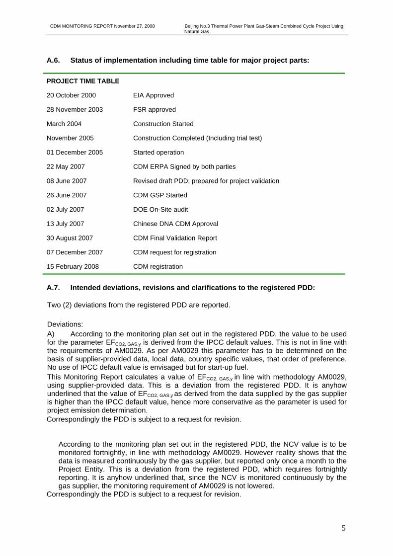
A.6. Status of implementation including time table for major project parts: PROJECT TIME TABLE
20 October 2000 EIA Approved
28 November 2003 FSR approved
March 2004 Construction Started
November 2005 Construction Completed (Including trial test)
01 December 2005 Started operation
22 May 2007 CDM ERPA Signed by both parties
08 June 2007 Revised draft PDD; prepared for project validation
26 June 2007 CDM GSP Started
02 July 2007 DOE On-Site audit
13 July 2007 Chinese DNA CDM Approval
30 August 2007 CDM Final Validation Report
07 December 2007 CDM request for registration
15 February 2008 CDM registration
A.7. Intended deviations, revisions and clarifications to the registered PDD: Two (2) deviations from the registered PDD are reported. Deviations: A) According to the monitoring plan set out in the registered PDD, the value to be used for the parameter EFCO2, GAS,y is derived from the IPCC default values. This is not in line with the requirements of AM0029. As per AM0029 this parameter has to be determined on the basis of supplier-provided data, local data, country specific values, that order of preference. No use of IPCC default value is envisaged but for start-up fuel. This Monitoring Report calculates a value of EFCO2, GAS,y in line with methodology AM0029, using supplier-provided data. This is a deviation from the registered PDD. It is anyhow underlined that the value of EFCO2, GAS,y as derived from the data supplied by the gas supplier is higher than the IPCC default value, hence more conservative as the parameter is used for project emission determination. Correspondingly the PDD is subject to a request for revision.
According to the monitoring plan set out in the registered PDD, the NCV value is to be monitored fortnightly, in line with methodology AM0029. However reality shows that the data is measured continuously by the gas supplier, but reported only once a month to the Project Entity. This is a deviation from the registered PDD, which requires fortnightly reporting. It is anyhow underlined that, since the NCV is monitored continuously by the gas supplier, the monitoring requirement of AM0029 is not lowered.
Correspondingly the PDD is subject to a request for revision.
CDM MONITORING REPORT November 27, 2008 Beijing No.3 Thermal Power Plant Gas-Steam Combined Cycle Project Using Natural Gas
6
Clarification: The parameters COEFcoal is listed in section B.7.1 of the registered PDD among data and parameters to be monitored, since its calculation needs to be re-made at the start of each subsequent crediting period (if applicable). However, to the purpose of this Monitoring Report, this parameter is not to be monitored since it is considered a fixed value over the first 7-years crediting period. Therefore this Monitoring Report does not list COEFcoal under section B.2.2 among the parameters to be monitored. This is not a deviation from the registered PDD, but a revision of the registered PDD it might be necessary for clarification.
A.8. Intended deviations or revisions to the registered monitoring plan (Decision 17/CP.7, Annex H, paragraph 57 to be considered): As stated above under A.7 two deviations from and one clarification to the registered monitoring plan have been applied to this Monitoring Report. Correspondingly the monitoring plan is subject to a request for revision. A.9. Changes since last verification: This monitoring report refers to the initial CDM verification of the project. Therefore, there is no change since last verification. A.10. Person(s) responsible for the preparation and submission of the monitoring report: Enecore Carbon Limited Tower 16, Unit 1601, Jianwai SOHO Jianwai Dajie, 39 – Chaoyang District - 100022 Beijing, China Tel. +86 10 5900 0701 Fax +86 10 5900 0706 Mr. Andrea Camponogara ([email protected])
Ms Alice Wang ([email protected])
Mr. Stuart Cerne ([email protected]) Beijing Jing Feng Gas Fired Power Co., Ltd. 15, Yungang Xi Road - Fengtai District - 100074 Beijing, China Tel. +86 10 83311133 Fax +86 10 83311409 Mr. Li Xiaobin ([email protected])
Mr. Tian Janmin ([email protected])
Mr. Yin Hao ([email protected])
SECTION B. Key monitoring activities according to the monitoring plan for the monitoring period stated in A.4. (referring to Decision 17/CP.7, Annex H, paragraph 53 (a) – (d) on data collection and archiving) B.1. Monitoring equipment:

CDM MONITORING REPORT November 27, 2008 Beijing No.3 Thermal Power Plant Gas-Steam Combined Cycle Project Using Natural Gas
7
B.1.2. Table providing Information on the equipment used (incl. manufacturer, type, serial number, date of installation, date of last calibration, information to specific uncertainty, need for changes and replacements):
Table B.1 – Equipment for monitoring electricity delivered to the grid
No. Line Name Switch No. Type S/N Accuracy Error Range Manufacturer
1 Lucheng I line (M) 2201 SL7000 36011671 0.2S ±0.2% Actaris
2 Lucheng I line (B) 2201 SL7000 36013901 0.2S ±0.2% Actaris
3 Start Backup Transformer (M) 100 B SL7000 36013778 0.2S ±0.2% Actaris
4 Start Backup Transformer (B) 100 B SL7000 36013848 0.2S ±0.2% Actaris
5 1# Generator 01 SL7000 36005323 0.5S ±0.5% Actaris
6 1# HV self service transformer
1# transformer SL7000 36005315 0.5S ±0.5% Actaris
Table B.2 - Equipment for monitoring the natural gas consumed
Name of equipment Type and specification Accuracy
4 Channel Advanced Ultrasonic Flow Meter
DN300 (12”), ANSI #600, 3400-3700-451-2 Speed range: 1m/s to 30m/s. Repeating rate: <5mm/s (better than +/-0.2%). Resolution: <1.0mm/s.
Non-demarcated ±0.5% Demarcated ±0.1%
CUI data processing software
Flow computer Daniel S600 type
Gas Chromatography EMERSON 2350 A
Pressure transmitter ROSEMOUNT, 3051S2TG4A2E 0.1s
Temperature transmitter ROSEMOUNT, 3144PD1A1E1M5T1 0.2s
Monitoring equipment’s positioning is given in Annex 3 to this Monitoring Report. B.1.3. Calibration procedures Calibration of meters
An agreement has been signed between the project owner and the North China Power Grid Co. regarding the on site calibration of gateway site meter, in compliance with “Technical administrative code of electric energy metering device” (DL/T448-2000), in order to ensure the quality of the meter calibration and the accuracy of electricity measurement. The project owner has commissioned the Electricity Energy Measurement Center of the North China Power Grid Co. to conduct a field test under real load to check the measurement error of the meters at the gateway site metering points on a regular basis. Meters n. 1, 2, 3 and 4 are calibrated, four times a year, with each calibration arranged every three months at the beginning of the each season. Meters n. 5 and 6 are calibrated once a year, every twelve months.
Details on calibration procedure are given in Table C below.

CDM MONITORING REPORT November 27, 2008 Beijing No.3 Thermal Power Plant Gas-Steam Combined Cycle Project Using Natural Gas
8
Table B.3 - Calibration Procedure for energy meters
No. Content of Procedure Responsible Party
Implementing Party
01 Sign meter calibration contract with NCEPRI NCPGC, PP NCEPRI
02 Establish calibration plan for the electricity meters PP, NCEPRI NCEPRI
03 Notice the NCEPRI on the schedule for calibration PP PP
04 NCEPRI staffs start the calibration work under the supervising by the power plant persons PP, NCEPRI PP, NCEPRI
05 Establish and implement security measure PP, NCEPRI PP, NCEPRI
06 Enter working field with special permission pass PP, NCEPRI PP, NCEPRI
07 At least two persons working together, one of them acting as supervisor PP, NCEPRI PP, NCEPRI
08 Set up marker plate or guardrail in the working area PP PP
09 Stand on well insulated mat, while working, and use on well insulated tool. PP PP
10 Inspect the working condition on site NCEPRI NCEPRI
11 Check environmental temperature (0-35)°C NCEPRI NCEPRI
12 Check voltage deviation against the rated value (not exceed ±10%) NCEPRI NCEPRI
13 Check frequency deviation against the rated value (not exceed ± 2%) NCEPRI NCEPRI
14 Check current load (not less than 10% of demar-cated current of the meter under calibration) NCEPRI NCEPRI
15 Check relative load stability NCEPRI NCEPRI
16 Dustproof and shockproof measure for the standard electricity energy meter NCEPRI NCEPRI
17 Check phase sequence and phase name mark for the standard meter NCEPRI NCEPRI
18 Check the insulation performance of the connecting lines between the standard meter and the testing terminal
NCEPRI NCEPRI
19 Check poles and phase name mark of the standard meter and the testing terminal
NCEPRI NCEPRI
20 Check the self-lock function between the standard meter and the testing terminal NCEPRI NCEPRI
21 Contacting check of the connecting lines with touch points between the standard meter and the testing terminal
NCEPRI NCEPRI
22 Check the electric potential difference between the standard meter and the corresponding electric pressure terminal of the meter under testing
NCEPRI NCEPRI
23 Inspect the equipment on-site, standard instrument and testing electric wires as a whole NCEPRI NCEPRI
24 Testing connection with measuring device NCEPRI NCEPRI
25 Connecting the electric pressure and current loop with monitoring instrument NCEPRI NCEPRI
26 Check the connection with the electricity energy meter charged NCEPRI NCEPRI

CDM MONITORING REPORT November 27, 2008 Beijing No.3 Thermal Power Plant Gas-Steam Combined Cycle Project Using Natural Gas
9
No. Content of Procedure Responsible Party
Implementing Party
27 Preheating the standard meter by connecting to the electric loop (not less than 15 minutes) NCEPRI NCEPRI
28 Measuring the error of the electricity energy meter under the real loading NCEPRI NCEPRI
29 Short circuit forbidden for electric pressure mutual inductor, and open circuit forbidden for electric current mutual inductor
NCEPRI NCEPRI
30 Backout testing connection NCEPRI NCEPRI
31 Internal clock calibration of the electricity energy meter NCEPRI NCEPRI
32 Battery check NCEPRI NCEPRI
33 Examine voltage lose event record NCEPRI NCEPRI
34 Check whether the sum of electricity with respective tariff rate is equal to the total electricity amount
NCEPRI NCEPRI
35 Internal calendar clock in electricity energy meter NCEPRI NCEPRI
36 Check correctness of time period setting corresponding to the given tariff rate NCEPRI NCEPRI
37 Check the accessing authority setting for the electricity energy meter and the number of recent coding as well as the time of the latest coding
NCEPRI NCEPRI
38 Check the load curve of the electricity energy meter NCEPRI NCEPRI
39 Check correctness of max. demand register setting NCEPRI NCEPRI
40 Check correctness of clearance date setting for the electricity energy meter NCEPRI NCEPRI
41 Acquiring device: comparison of electricity energy meter data with data acquired at the main station NCEPRI NCEPRI
42 On-site verification of the original record of the electricity energy meter NCEPRI NCEPRI
43 Calibration results treatment NCEPRI NCEPRI
44 Resuming the calibration equipment to the working status before the calibration NCEPRI, PP NCEPRI, PP
45 End the calibration, expiring the special permission pass and leaving. PP PP
Calibrations of natural gas metering devices The project owners has signed agreement with the gas supplier for periodic calibration and testing on the precision of the gas metering devices, in order to ensure the monitoring accuracy on the natural gas consumption and its content analysis. The calibration and testing for the two natural gas metering devices has been conducted by the gas supplier once every two year, according to the national measurement standard and regulation. B.1.4. Involvement of Third Parties The following third-parties are involved:
- Enecore Carbon Limited, as consultancy firm in charge for the Monitoring Report drafting and emission reduction calculation;
- The North China Electric Power Research Institute (NCEPRI), as responsible for calibration procedure;

CDM MONITORING REPORT November 27, 2008 Beijing No.3 Thermal Power Plant Gas-Steam Combined Cycle Project Using Natural Gas
10
- The North China Power Grid Co. (NCPGC), in its role of controller of the electricity delivered to the grid by the project owner;
- The Beijing Gas Group Co. Ltd, in its role of controller of the natural gas supplied to the project owner.
B.2. Data collection (recorded data for the whole monitoring period and data from invoices in the respective period): B.2.1. List of fixed default values: Data / Parameter: EFBL,CO2 – Baseline Emission Factor Value applied: 0.8823387 tCO2e/MWh Source: As per registered PDD Data / Parameter: EFBL,upstream,CH4 - Fugitive CH4 upstream emission of a 600MW
sub-critical coal-fired plant Value applied: 5.7208 x 10⁻⁶ tCH4/MWh Source: As per registered PDD Data / Parameter: GWPCH4 – Global Warming Potential of Methane Value applied: 21 Source: IPCC default value Data / Parameter: EFNG,upstream,CH4 - Fugitive CH4 upstream emission of natural
gas Value applied: 296 t CH4/PJ Source: IPCC default value B.2.2. List of variables: Data / Parameter: NCVNG,y – Net calorific value Data unit: MJ/Nm3 Source: Gas supplier Value of data applied for the purpose of calculating emission reductions
34.7697 (weighted average)
Any comment: NCV value is monitored continuously by the gas supplier and reported monthly to the Project Entity. The value used is the weighted average of the values monthly provided from February to June 2008.
Data / Parameter: FCNG,y – Quantity of natural gas consumed in the monitoring
period Data unit: Nm3 Source: Meter readings Value of data applied for the purpose of calculating emission reductions
167,169,370.00
Any comment: Recorded data have been cross-checked against invoice data and no significant different has been observed
CDM MONITORING REPORT November 27, 2008 Beijing No.3 Thermal Power Plant Gas-Steam Combined Cycle Project Using Natural Gas
11
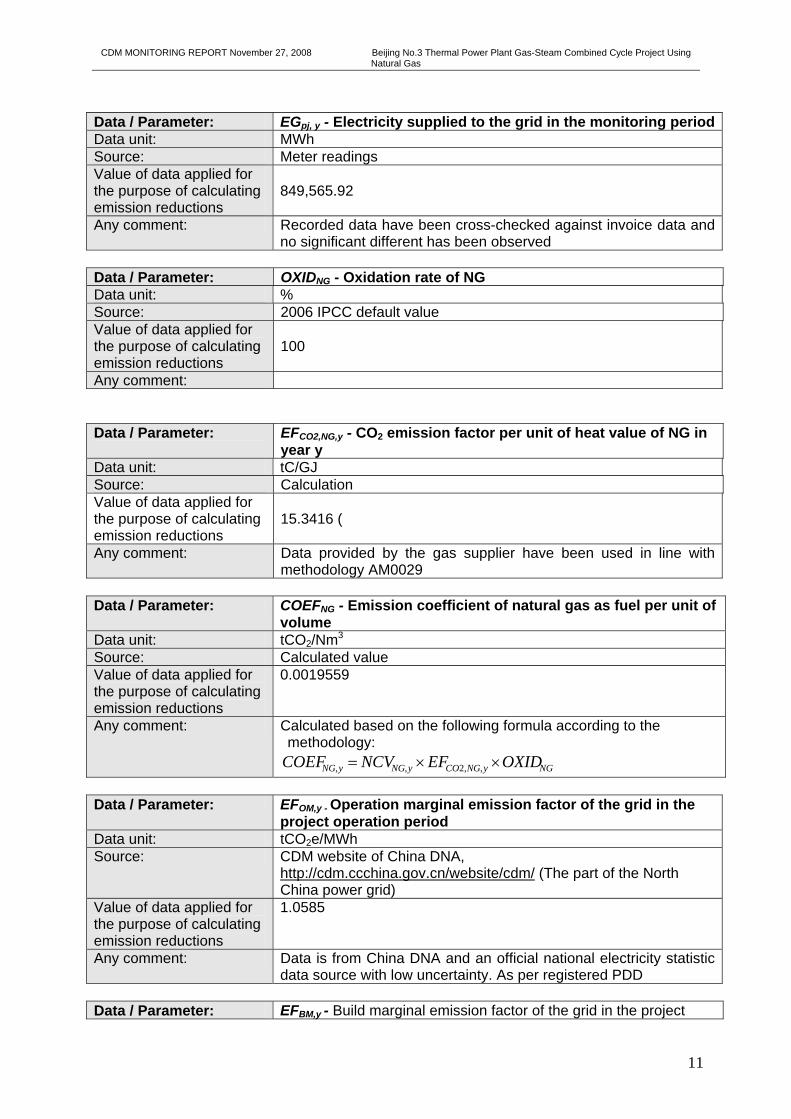
Data / Parameter: EGpj, y - Electricity supplied to the grid in the monitoring periodData unit: MWh Source: Meter readings Value of data applied for the purpose of calculating emission reductions
849,565.92
Any comment: Recorded data have been cross-checked against invoice data and no significant different has been observed
Data / Parameter: OXIDNG - Oxidation rate of NG Data unit: % Source: 2006 IPCC default value Value of data applied for the purpose of calculating emission reductions
100
Any comment: Data / Parameter: EFCO2,NG,y - CO2 emission factor per unit of heat value of NG in
year y Data unit: tC/GJ Source: Calculation Value of data applied for the purpose of calculating emission reductions
15.3416 (
Any comment: Data provided by the gas supplier have been used in line with methodology AM0029
Data / Parameter: COEFNG - Emission coefficient of natural gas as fuel per unit of
volume Data unit: tCO2/Nm3 Source: Calculated value Value of data applied for the purpose of calculating emission reductions
0.0019559
Any comment: Calculated based on the following formula according to the methodology:
NGyNGCOyNGyNG OXIDEFNCVCOEF ××= ,,2,, Data / Parameter: EFOM,y - Operation marginal emission factor of the grid in the
project operation period Data unit: tCO2e/MWh Source: CDM website of China DNA,
http://cdm.ccchina.gov.cn/website/cdm/ (The part of the North China power grid)
Value of data applied for the purpose of calculating emission reductions
1.0585
Any comment: Data is from China DNA and an official national electricity statistic data source with low uncertainty. As per registered PDD
Data / Parameter: EFBM,y - Build marginal emission factor of the grid in the project

CDM MONITORING REPORT November 27, 2008 Beijing No.3 Thermal Power Plant Gas-Steam Combined Cycle Project Using Natural Gas
12
operation period Data unit: tCO2e/MWh Source: CDM website of China DNA,
http://cdm.ccchina.gov.cn/website/cdm/ (The part of the North China power grid)
Value of data applied for the purpose of calculating emission reductions
0.9066
Any comment: Data is from China DNA and an official national electricity statistic data source with low uncertainty. As per registered PDD
Data / Parameter: EFy - Combined marginal emission factor of the grid in the
project period Data unit: tCO2e/MWh Source: CDM website of China DNA,
http://cdm.ccchina.gov.cn/website/cdm/ (The part of the North China power grid)
Value of data applied for the purpose of calculating emission reductions
0.98255
Any comment: Data is from China DNA and an official national electricity statistic data source with low uncertainty. As per registered PDD
B.2.3. Data concerning GHG emissions by sources of the project activity (referring to paragraph 53(a)): Table B.4 and B.5 below show all collected data from February 15, 2008 to June 30, 2008. All relevant data are also reported in Appendix B to this Monitoring Report.
Table B.4 - Recorded and invoice data of natural gas consumption and power generation
RECORDED DATA INVOICE DATA
Month Year Gas
Consumption (Nm3)
Power Supplied to the Grid
(MWh)
Gas Consumption
(Nm3)
Power Supplied to the Grid
(MWh) February 2008
7,261,600.00 33,888.49 8,014,540.00 33,943.80
March 2008 26,117,770.00 122,757.16
26,117,770.00
122,769.90
April 2008 45,524,000.00 235,459.36
45,524,000.00
235,471.50
May 2008 44,252,000.00 232,214.53
44,252,000.00
232,250.70
June 2008 44,014,000.00 225,246.38
44,014,000.00
225,258.00 TOTAL 167,169,370.00 849,565.92 167,922,310.00 849,693.90
Table B.5 – NCV net values of NG as reported by the gas supplier
Month NCV Value MJ/Nm3
CDM MONITORING REPORT November 27, 2008 Beijing No.3 Thermal Power Plant Gas-Steam Combined Cycle Project Using Natural Gas
13
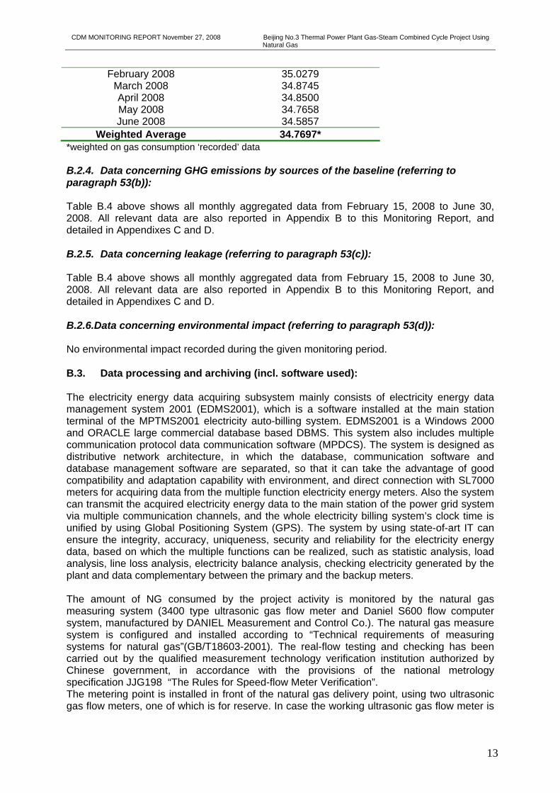
February 2008 35.0279 March 2008 34.8745 April 2008 34.8500 May 2008 34.7658 June 2008 34.5857
Weighted Average 34.7697* *weighted on gas consumption ‘recorded’ data B.2.4. Data concerning GHG emissions by sources of the baseline (referring to paragraph 53(b)): Table B.4 above shows all monthly aggregated data from February 15, 2008 to June 30, 2008. All relevant data are also reported in Appendix B to this Monitoring Report, and detailed in Appendixes C and D. B.2.5. Data concerning leakage (referring to paragraph 53(c)): Table B.4 above shows all monthly aggregated data from February 15, 2008 to June 30, 2008. All relevant data are also reported in Appendix B to this Monitoring Report, and detailed in Appendixes C and D. B.2.6.Data concerning environmental impact (referring to paragraph 53(d)): No environmental impact recorded during the given monitoring period. B.3. Data processing and archiving (incl. software used): The electricity energy data acquiring subsystem mainly consists of electricity energy data management system 2001 (EDMS2001), which is a software installed at the main station terminal of the MPTMS2001 electricity auto-billing system. EDMS2001 is a Windows 2000 and ORACLE large commercial database based DBMS. This system also includes multiple communication protocol data communication software (MPDCS). The system is designed as distributive network architecture, in which the database, communication software and database management software are separated, so that it can take the advantage of good compatibility and adaptation capability with environment, and direct connection with SL7000 meters for acquiring data from the multiple function electricity energy meters. Also the system can transmit the acquired electricity energy data to the main station of the power grid system via multiple communication channels, and the whole electricity billing system’s clock time is unified by using Global Positioning System (GPS). The system by using state-of-art IT can ensure the integrity, accuracy, uniqueness, security and reliability for the electricity energy data, based on which the multiple functions can be realized, such as statistic analysis, load analysis, line loss analysis, electricity balance analysis, checking electricity generated by the plant and data complementary between the primary and the backup meters. The amount of NG consumed by the project activity is monitored by the natural gas measuring system (3400 type ultrasonic gas flow meter and Daniel S600 flow computer system, manufactured by DANIEL Measurement and Control Co.). The natural gas measure system is configured and installed according to “Technical requirements of measuring systems for natural gas”(GB/T18603-2001). The real-flow testing and checking has been carried out by the qualified measurement technology verification institution authorized by Chinese government, in accordance with the provisions of the national metrology specification JJG198 “The Rules for Speed-flow Meter Verification”. The metering point is installed in front of the natural gas delivery point, using two ultrasonic gas flow meters, one of which is for reserve. In case the working ultrasonic gas flow meter is

CDM MONITORING REPORT November 27, 2008 Beijing No.3 Thermal Power Plant Gas-Steam Combined Cycle Project Using Natural Gas
14
detected in fault, the system will alarm automatically, then the system prompt start up the standby ultrasonic gas flow meter and close the faulted ultrasonic gas flow meter. The project owner has signed an urban gas supply contract with the Beijing Gas Group Co. ltd., under which the natural gas supply monitoring will be implemented in detail. B.4. Special event log: No special event log occurred during the given monitoring period of this Monitoring Report.

CDM MONITORING REPORT November 27, 2008 Beijing No.3 Thermal Power Plant Gas-Steam Combined Cycle Project Using Natural Gas
15
SECTION C. Quality assurance and quality control measures C.1. Documented procedures and management plan: C.1.1. Roles and responsibilities: A CDM Group has been set up internally by Beijing Jingfeng Gas Fired Power Co. The CDM Group is in charge, inter alia, of the implementation and management of the whole monitoring plan, including monitoring and management of CDM data.
The vice general manager of Beijing Jingfeng Gas Fired Power Co. (i.e Mr. Tian Jianmin) is the leader of the CDM group responsible for all the relevant activities during project operations and maintaining period. Mr. Zhou Fusheng, Chief Engineer of the Beijing Jingfeng Gas Turbine Power Co. is responsible for the supervision and correct work of the CDM monitoring group. The leader of the Maintenance Department (i.e. Mr. Cao Mansheng) and the vice leader of the Safety Department (i.e. Mr. Li Xiaobin) are responsible for organizing and managing the data reading.
An Operation Manual developed by the Safety Department describes all process responsibilities and data processing system. The Manual incorporates natural gas-turbine technical standard guidelines with CDM process management. The Operational Manual is made available to verifying DOE. C.1.2. Trainings: The staff, including the CDM Group, has been be trained about correct operation and maintenance of Beijing Jingfeng natural gas plant by the equipment manufacturing company, according to the training contract included in the equipment procurement contract. In addition, the CDM consultants (i.e. Enecore Carbon Limited and Beijing Huajinhao Company) provided training on CDM procedures and methodologies. C.2. Involvement of Third Parties: There is no involvement of third parties, but the CDM consultants (i.e. Enecore Carbon Limited and Beijing Huajinhao Company). C.3. Internal audits and control measures: Data Reading: the on-duty (in shift) staffs in the Operation Department, are responsible for the data monitoring and recording in the log book daily, especially the electricity generated, electricity delivered to the grid and the quantity of natural gas consumed every day.
Data Verification: the statistical staffs in the Planning & Finance Department are in charge of verification and confirmation for the monitoring data records, which will be aggregated and reported to CDM Group leader monthly. After checking and ensuring without material mistake, this data are archived and also sent to the Director of the Finance Department which makes financial clearance with the power Grid Company and natural gas Supply Company on the electricity sale and the gas payment respectively. The invoices are archived and managed by the Director of Finance Department.
Meter Supervision: technicians specialised in electric measuring/thermal engineering, are responsible for the daily maintenance and supervision of the electricity energy meters and the natural gas flow meters, including their periodic calibration. C.4. Troubleshooting procedures:

CDM MONITORING REPORT November 27, 2008 Beijing No.3 Thermal Power Plant Gas-Steam Combined Cycle Project Using Natural Gas
16
Possible unexpected cases and relevant emergency responses are listed in the table below.
No. Unexpected case Emergency response measure
01 Voltage loss of power supply at data acquiring device
Measuring the power supply voltage, try to find out the cause, remove the troubles, resume electricity supply ASAP, reducing the loss of electricity.
02 Voltage loss of power supply at the electricity energy meter
Measuring the power supply voltage at the electricity energy meter and the electric circuit, try to find out the cause, and remove the troubles
03 Strike of light at electric current terminal
Shorting the current circuit, try to find out the cause, and remove the troubles
04 Short circuit of the voltage loop Turn off the small switch at the electric pressure mutual inductor
05 Fault in communication system
Measuring the voltage at the communication terminals, try to find out the cause, and remove the troubles
None of the unexpected cases listed above occurred during the given monitoring period.
CDM MONITORING REPORT November 27, 2008 Beijing No.3 Thermal Power Plant Gas-Steam Combined Cycle Project Using Natural Gas
17
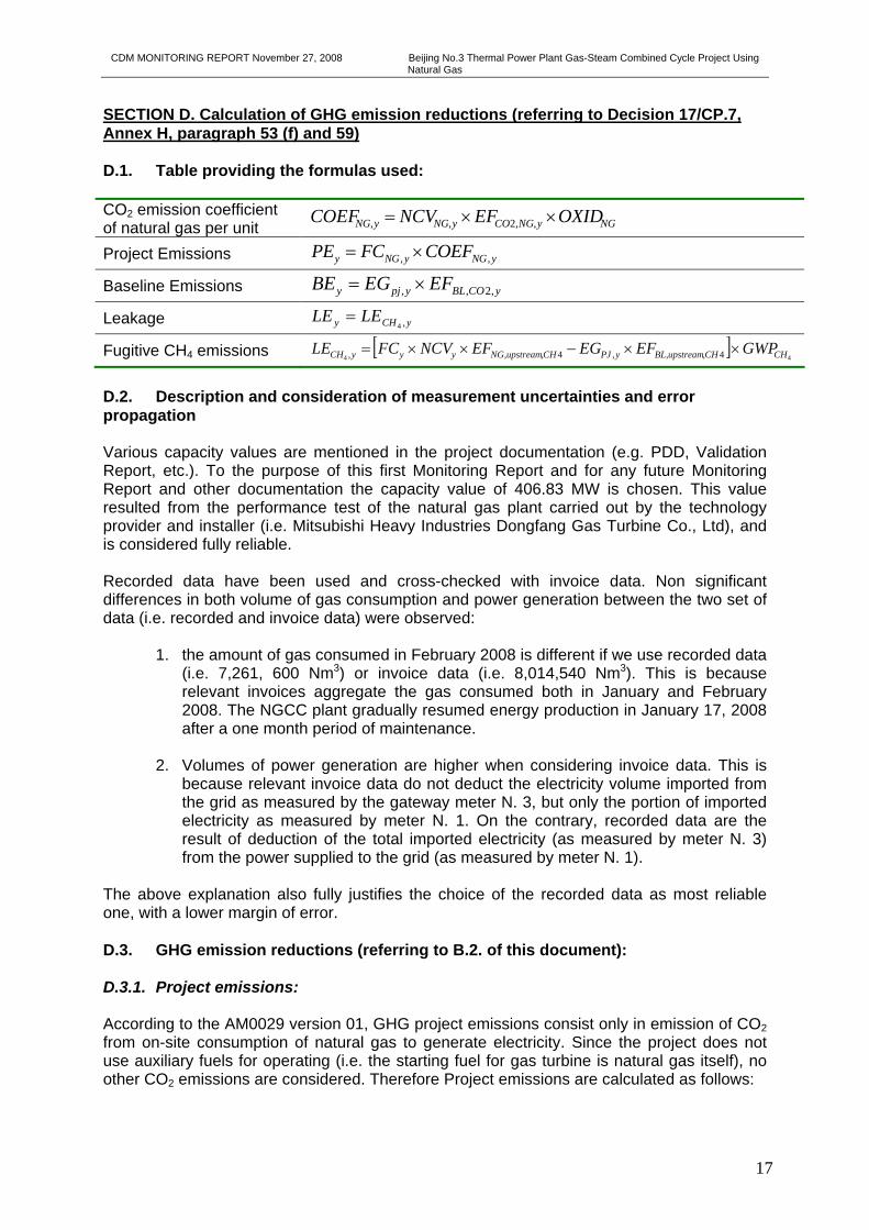
SECTION D. Calculation of GHG emission reductions (referring to Decision 17/CP.7, Annex H, paragraph 53 (f) and 59) D.1. Table providing the formulas used: CO2 emission coefficient of natural gas per unit NGyNGCOyNGyNG OXIDEFNCVCOEF ××= ,,2,,
Project Emissions , ,y NG y NG yPE FC COEF= ×
Baseline Emissions yCOBLypjy EFEGBE ,2,, ×=
Leakage yCHy LELE ,4=
Fugitive CH4 emissions [ ]44 4,,,4,,, CHCHupstreamBLyPJCHupstreamNGyyyCH GWPEFEGEFNCVFCLE ××−××=
D.2. Description and consideration of measurement uncertainties and error propagation Various capacity values are mentioned in the project documentation (e.g. PDD, Validation Report, etc.). To the purpose of this first Monitoring Report and for any future Monitoring Report and other documentation the capacity value of 406.83 MW is chosen. This value resulted from the performance test of the natural gas plant carried out by the technology provider and installer (i.e. Mitsubishi Heavy Industries Dongfang Gas Turbine Co., Ltd), and is considered fully reliable. Recorded data have been used and cross-checked with invoice data. Non significant differences in both volume of gas consumption and power generation between the two set of data (i.e. recorded and invoice data) were observed:
1. the amount of gas consumed in February 2008 is different if we use recorded data (i.e. 7,261, 600 Nm3) or invoice data (i.e. 8,014,540 Nm3). This is because relevant invoices aggregate the gas consumed both in January and February 2008. The NGCC plant gradually resumed energy production in January 17, 2008 after a one month period of maintenance.
2. Volumes of power generation are higher when considering invoice data. This is
because relevant invoice data do not deduct the electricity volume imported from the grid as measured by the gateway meter N. 3, but only the portion of imported electricity as measured by meter N. 1. On the contrary, recorded data are the result of deduction of the total imported electricity (as measured by meter N. 3) from the power supplied to the grid (as measured by meter N. 1).
The above explanation also fully justifies the choice of the recorded data as most reliable one, with a lower margin of error. D.3. GHG emission reductions (referring to B.2. of this document): D.3.1. Project emissions: According to the AM0029 version 01, GHG project emissions consist only in emission of CO2 from on-site consumption of natural gas to generate electricity. Since the project does not use auxiliary fuels for operating (i.e. the starting fuel for gas turbine is natural gas itself), no other CO2 emissions are considered. Therefore Project emissions are calculated as follows:

CDM MONITORING REPORT November 27, 2008 Beijing No.3 Thermal Power Plant Gas-Steam Combined Cycle Project Using Natural Gas
18
First we calculate the emission coefficient of NG using the formula below:
NGyNGCOyNGyNG OXIDEFNCVCOEF ××= ,,2,, (1) Where: NCVNG,y: the net calorific value of NG (MJ/Nm3), 34.7697 MJ/Nm3 (weighted average of the NCV values
monthly provided by the gas supplier). EFCO2,NG,y: the CO2 emission factor per unit of heat value of NG in year y, 15.3416 tC/TJ, measured using
supplier-provided data in line with AM0029. See Appendix B for detail on calculation. OXIDNG: the oxidation rate of NG, the 2006 IPCC default value 100% is used. COEFNG,y = 34.7697 MJ/Nm3 × 1 × 15.3416 tC/TJ×44/12/1000000 = 0.0019559 tCO2e/Nm3 Then, project emissions are calculated applying the below formula, where the quantity of natural gas consumed by the project activity during the monitoring period (FGNG,y) is multiplied by the calculated emission coefficient of NG (COEFNG,y).
yNGyNGy COEFFGPE ,, ×= (2) PE = 167,169,370.00 Nm3 × 0.0019559 tCO2e/Nm3 = 326,963.85 tCO2e D.3.2. Baseline emissions: According to the below formula, baseline emissions are calculated as the electricity supplied to the grid by the project (EGpj,y) multiplied by the baseline CO2 emission factor (EFBL,CO2,y).
yCOBLypjy EFEGBE ,2,, ×= (3)
As stated in the registered PDD, project participants chose Option 3 among the options offered by methodology AM0029 version 01 for selection of the baseline emission factor (EFBL,CO2,y). Option 3 is the emission factor of the technology (and fuel) identified as the most likely baseline scenario.
As per explanation in Section B.6.1 of the registered PDD, a 600 MW sub-critical coal-fired power plant has been identified as the most likely baseline scenario. The calculated emission factor for this technology (EFBL,CO2,Option3) is
EFBL,CO2,y = EFBL,CO2,Option3 = 0.8823387 tCO2e/MWh.
Subsequently, baseline emissions are calculated as electricity supplied to the grid by the project (EGpj,y) during the monitoring period multiplied by the calculated baseline CO2 emission factor:
BE = 849,565.92 MWh × 0.8823387 tCO2e/MWh = 749,604.89 tCO2e D.3.3. Leakage: Leakage may result from upstream processes of fossil fuels outside of the project boundary. This includes mainly fugitive CH4 emissions and CO2 emissions from associated fuel combustion and flaring. In according to the AM0029 version 01, the following leakage emission sources are considered:
• LECH4,y: Fugitive CH4 emissions associated with fuel extraction, processing, liquefaction, transportation, re-gasification and distribution of natural gas used in the project plant and fossil fuels used in the grid in the absence of the project activity.

CDM MONITORING REPORT November 27, 2008 Beijing No.3 Thermal Power Plant Gas-Steam Combined Cycle Project Using Natural Gas
19
• LENG,CO2,y: In the case NG is used in the project plant: CO2 emission from fuel combustion/ electricity consumption associated with the liquefaction, transportation, re-gasification and compression into a natural gas transmission or distribution system.
In the case of the proposed project, no LNG consumption is used as fuel in the project activity. Therefore, Project leakage is calculated only as fugitive CH4 emissions (LECH4,y), as per following formula:
yCHy LELE ,4= (4)
Fugitive CH4 emissions (LECH4,y) are calculated multiplying the NG quantity consumed by the project in year y with the emission factor for fugitive CH4 emissions (EFNG,upstream,CH4) due to NG consumption and subtract the fugitive CH4 emissions occurring from fossil fuels used in the selected baseline power plant in the absence of the project activity, according to the following formula:
[ ]4444 ,,,,,, CHCHupstreamBLyPJCHupstreamNGyyyCH GWPEFEGEFNCVFCLE ××−××= (5)
A default value of 296 tCH4/PJ is used for EFNG,upstream,CH4.
As per Section B 6.3 of the registered PDD, the emission factor of a 600 MW sub-critical coal-fired power plant with the lowest levelised unit generation cost is selected as baseline emission factor. Thus the corresponding upstream fugitive CH4 emission factor is:
EFBL,upstream,CH4 = 5.7208 x 10⁻⁶ tCH4/MWh
Then, project fugitive CH4 emissions (LECH4,y) are calculated for the given monitoring period.
LE = [(167,169,370 × 34.7697 × 2.96×10-7) – 849,565.92 × 5.7208 x 10-6 ] × 21 = 36,027.99 tCO2e D.2.4. Summary of the emissions reductions during the monitoring period: The emission reduction of the proposed project can be calculated as follows:
yyyy LEPEBEER −−= (6) ERy = 749,604.89 tCO2e – 326,963.85 tCO2e – 36,027.99 tCO2e = 386,613.05 tCO2e An excel spreadsheet summurising calculation of emission reductions is given in Appendix B to this Monitoring Report.

CDM MONITORING REPORT November 27, 2008 Beijing No.3 Thermal Power Plant Gas-Steam Combined Cycle Project Using Natural Gas
20
Annex 1 – Definition and Acronyms
Acronyms CER – Certified Emission Reductions CDM – Clean Development Mechanism DNA – Designated National Authority DOE – Designated Operational Entity EIA – Environmental Impact Assessment ERPA – Emission Reduction Purchase Agreement FSR – Feasibility Study Report GHG – Greenhouse Gases GPS – Global Positioning System IPCC – Intergovernmental Panel on Climate Change LNG – Liquefied Natural Gas MPDCS - Communication Protocol Data Communication Software NCEPRI - North China Electric Power Research Institute NCPG – North China Power Grid NCPGC – North China Power Grid Company PDD – Project Designed Document PP – Project Participants UNFCCC – United Nation Framework Convention on Climate Change

CDM MONITORING REPORT November 27, 2008 Beijing No.3 Thermal Power Plant Gas-Steam Combined Cycle Project Using Natural Gas
21
Annex 2 - Technical drawing – Primary line configuration diagram
节水低压变压器
柴油机成套
保安动力中心
综合水泵房
循环水 节水
循环水低压变压器 循环水低压变压器 节水低压变压器
余热炉保安
公用
公用PC
燃机余热炉
燃机
主厂房
燃机保安
公用低压变压器 主厂房低压变压器公用低压变压器 主厂房低压变压器
至SFC
号高压厂用变压器
线路
SFC
1 61 1 -1 9 1 61 2-1 9
1 61 21 61 1
1 M 2M
1 61 1 -9
1 601 1 6451 643
1 61 2-9
1 602 1 602-2
0. 2/3p/3p/6p1 00/1 00/1 00/1 00VA测量,计量/保护/保护/保护
主变B屏
主变A屏
测量
线路保护
线路保护
计量
故录
备用
备用
520MVA242+2* 2. 5%/20KV
0. 245VA测量,计量
3p/6p1 00/1 00VA同期,保护/保护
01 MK#1 燃机发电机407. 69MW20KV50HZ
故录测量计量
主变 高厂变B屏
主变 高厂变A屏
01 BBTASFZL7-25000/2025000KVA
20± 8* 1 . 25%/6. 3KVD,yn1Ud+1 0. 5%
1 7. 32欧
3P/3P 50VA/50VA
测量故录高厂变A屏
高厂变B屏高厂变B屏
高厂变A屏故录
测量
6. 3KV 高压厂用01 BBB段
1 641
6KV 备用段10BBC
6. 3± 2* 2. 5%/0. 4KVUd+8% D, YN1 1
6. 3± 2* 2. 5%/0. 4KVUd+8% D, YN1 1
6. 3± 2* 2. 5%/0. 4KVUd+8% D, YN1 1
6. 3± 2* 2. 5%/0. 4KVUd+8% D, YN1 1
6. 3± 2* 2. 5%/0. 4KVUd=1 0% D, YN1 1
6. 3± 2* 2. 5%/0. 4KVUd=1 0% D, YN1 1
6. 3± 2* 2. 5%/0. 4KVUd=1 0% D, YN1 1
6. 3± 2* 2. 5%/0. 4KVUd=1 0% D, YN1 1
6. 3KV 高压厂变01 BBA段
1 7. 32欧
00BCT高压厂用备用变压器SFZL7-25000/1 1 025000KVA1 1 0± 8* 1 . 25%/6. 3KVYN,yn0, dUd=1 0. 5%
COSΦ=0. 85
COSΦ=0. 8
北南 南 南北
#1 高压锅炉给水泵
#1 循环水泵
#1 凝结水泵
备用 #2高压锅炉给水泵
#2循环水泵
#2凝结水泵
机组起励电源
备用
41 241 1 41 2-941 1 -9 42141 7 41 841 7-9 41 8-947841 5 41 6
41 5-9 41 6-945641 3 41 441 3-9 41 4-9434
1 601 -2
备用
图号 F21 7S-D0501 -01
厂用电原理接线图
#1 励磁变压器3930KVA Ud=8%20/0. 69KV Y, d1 1
1 00乙
7-0乙
1 603-21 603-9
#0 乙启备变
1 6421 6441 6461 6481 647 1 649
1 00乙-4 1 00乙-5
MCC31 3
31 3
MCC31 4
314
E-PC205
EMCC335
MCC325
MCC31 5
31 5 31 6
325 326
335 336 E-PC202 346 E-PC
201
MCC31 6
MCC326
EMCC336
EMCC346
E-PC206
206 205 202201
200
-2 200-9
MCC31 7
31 7
MCC31 8
31 8
2201 -9
2201
2201 -27 2201 -2 2201 -1 7
01
01 -27
01 -1 7
01 -49 01 -59
01 -07
01 -1 901 -2901 -39
01 -2
#1 、#2Meteri ng system
#3、#4Meteri ng system
#5Meteri ng system#6Meteri ng system
CDM MONITORING REPORT November 27, 2008 Beijing No.3 Thermal Power Plant Gas-Steam Combined Cycle Project Using Natural Gas
22
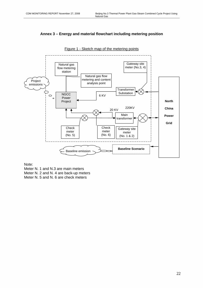
Annex 3 – Energy and material flowchart including metering position
Figure 1 - Sketch map of the metering points
Note: Meter N. 1 and N.3 are main meters Meter N. 2 and N. 4 are back-up meters Meter N. 5 and N. 6 are check meters
Natural gas flow metering
station
NGCC Power Project
North
China
Power
Grid
Transformer Substation
Project emissions
Baseline emission
20 KV
6 KV
220KV
Check meter (No. 5)
Gateway site meter
(No. 1 & 2)
Check meter (No. 6)
Gateway site meter (No.3, 4)
Natural gas flow metering and content
analysis point
Baseline Scenario
Main transformer

CDM MONITORING REPORT November 27, 2008 Beijing No.3 Thermal Power Plant Gas-Steam Combined Cycle Project Using Natural Gas
23
Figure 2 – Flow gas diagram and flow gas meter position
GF201 JY- ESD M PI
2101 PT
2101 TI
2101 TT
2101 M
XF201
PI2501
LS2501
PI2502
M
XF202
PI2503 LS
2502
PI2504
M
接标定车
M
M
S
M
PI 2403
GF202
M
S
S
M
PI 2405
M
A 24
01PI 24
01PT 24
01TI 24
01
装车
氮气吹扫
PI 2201
LI 22
01
残液罐 G201
KC201
M
SL201
H205 813 L415MB
H206 508 L415MB
H207 508 L415MB
M PI2409
M PI 2410
PI2412 三菱公司精过滤器
仪表风
减压阀
除盐水
氮气吹扫
ESDPI 2601
PT 2601
PT 2602
TI 2601
TT 2601
去天然气燃
KF20
吕村来气
2101 2103
114.3X5.2 L245
508X14.3 L145MB 2501
2502
2503
2504
2505
2506
2507
2510
2513
FE2501 GAS METER
FE2502 GAS METER
2516
2508
2509
2511
2512
2514
2515
H201 508 L415MB
H202 508 L415MB
H203 508 L415MB
2418
2420
2422
2417
2419
2421
H204 508 L415MB
2416
2601 2415
2402 2406 2407
2403
GL2401 FE2401
2404 2405
进水
出水
2423
2424
预留二期接口 TT 24
02
PT 24
02
TI 24
02
PI 24
02
2409
2411
2413
PCV2401 PCV2402
PCV2403 PCV2404
2410
2412
2414 2408
PI2413
PT
2403
预留二期接口
355.6
355.6 60.3
114.3
大小头DN350×DN300
508×14.3 L415MB
预留二期接口
预留二期接口
114.3×5.2 L245
114.3×5.2 L245
预留二期接口
压缩机组
21701
21702
25701 25702
25703
25704
25602
25601
25604 25603
25713
25714
25715
25716
25717
25718
见附图2
见附图2
S
24701
24702
24704 24703
24737
24738
24739
24740
27705
27706
26702
26703 26701
22701
22702阻
火
器
26704
26705
24719 24720
24722 24723
24724
24744
24743
24746 24745
24747 24748
27618
27619
22602
22601
22704
22705 24621
24622 2425
2426
2427
2602
见附图1
见附图3
放空管
见详图4
侦测阀
24721
22703
22603
PI 2404
PI 2406
PI 2407
PI2408
PI2411

CDM MONITORING REPORT November 27, 2008 Beijing No.3 Thermal Power Plant Gas-Steam Combined Cycle Project Using Natural Gas
24
Figure 3 - Structure Diagram of the Remote Electricity Billing System
Ethernet High Way
L-PRT
PSTN/MicroWave
MODEM Pool Data Server
Dispatching Center of North China Grid
C2000
L-PRT
LAN
No.1 Lucheng I Line (M)
No.2 Lucheng I Line (B)
RS485EDAD2001-C
Data Server Data Server
Jingfeng Gas Turbine SubStation
MPTMS2001
Modem
L-PRT
Jingfeng Thermal Power Station
MPTMS2001 Data Server Data Server
LAN Modem
No.3 Start Backup Trans-
former (M)
No.4 Start Backup Trans-
former (B)
No.5 #1 Generator
Unit
No.6 #1HV Plant Trans-
former
Related Documents