Steady-State Sinusoidal Analysis 1. Identify the frequency, angular frequency, peak value, rms value, and phase of a sinusoidal signal. 2. Solve steady-state ac circuits using phasors and complex impedances.

Steady-State Sinusoidal Analysis 1. Identify the frequency, angular frequency, peak value, rms value, and phase of a sinusoidal signal. 2. Solve steady-state.
Dec 21, 2015
Welcome message from author
This document is posted to help you gain knowledge. Please leave a comment to let me know what you think about it! Share it to your friends and learn new things together.
Transcript

Steady-State Sinusoidal Analysis
1. Identify the frequency, angular frequency, peak value, rms value, and phase of a sinusoidal signal.
2. Solve steady-state ac circuits using phasors and complex impedances.
4. Find Thévenin and Norton equivalent circuits.
5. Determine load impedances for maximum power transfer.
6. Solve balanced three-phase circuits.
3. Compute power for steady-state ac circuits.
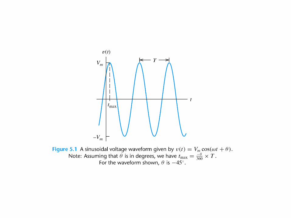
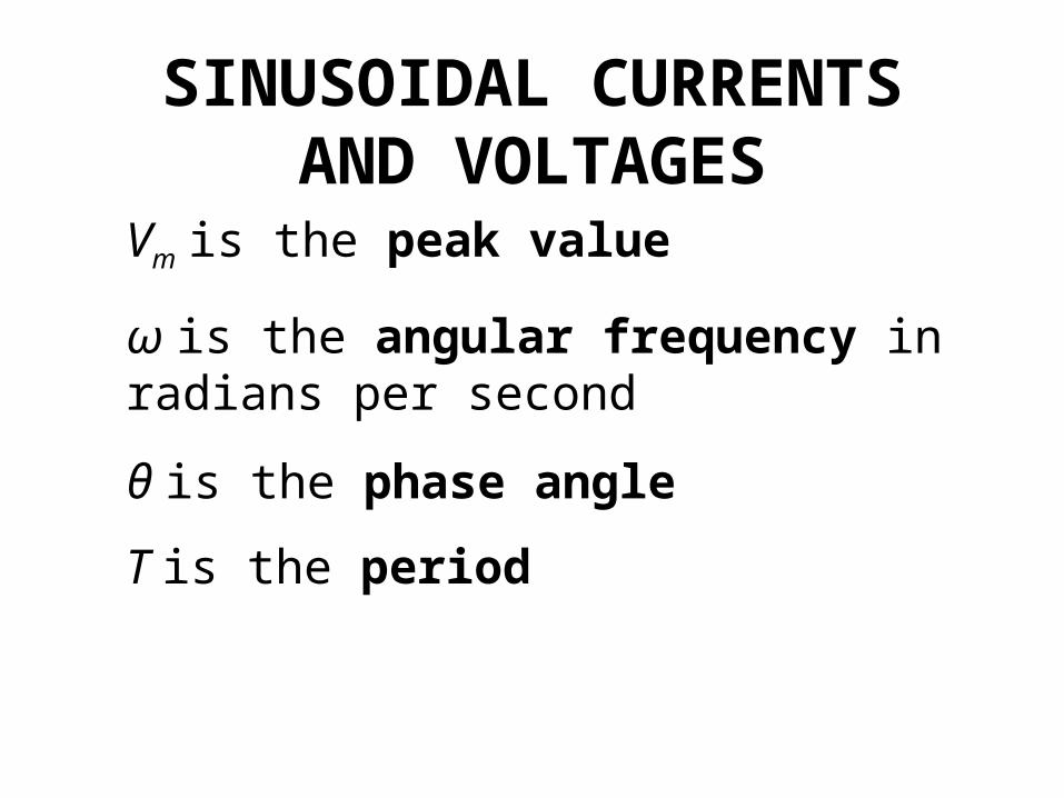
SINUSOIDAL CURRENTS AND VOLTAGES
Vm is the peak value
ω is the angular frequency in radians per second
θ is the phase angle
T is the period

T
2
f 2
90cossin zz
Frequency T
f1
Angular frequency

Root-Mean-Square Values
dttvT
VT
2
0
rms
1
R
VP
2rms
avg
dttiT
IT
2
0
rms
1
RIP 2rmsavg
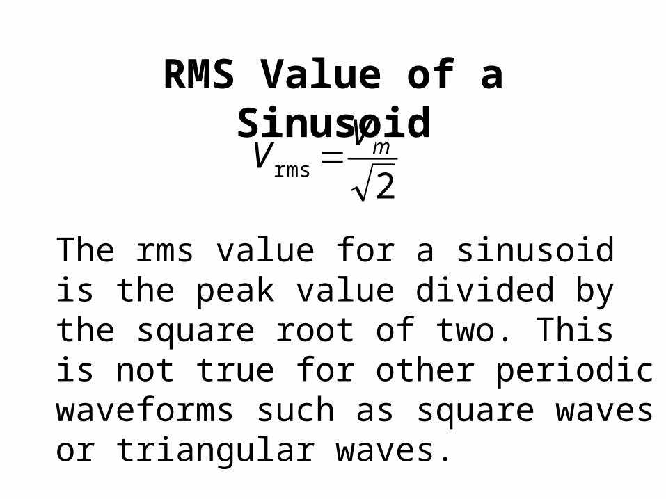
RMS Value of a Sinusoid
2rms
mVV
The rms value for a sinusoid is the peak value divided by the square root of two. This is not true for other periodic waveforms such as square waves or triangular waves.


Phasor Definition
111 cos :function Time θtωVtv
111 :Phasor θVV

Adding Sinusoids Using Phasors
Step 1: Determine the phasor for each term.Step 2: Add the phasors using complex arithmetic.Step 3: Convert the sum to polar form.
Step 4: Write the result as a time function.

Using Phasors to Add Sinusoids 45cos201 ttv
60cos102 ttv
45201 V
30102 V
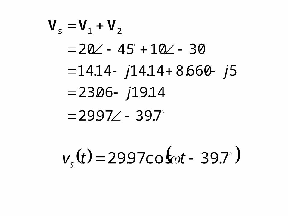
7.3997.29
14.1906.23
5660.814.1414.14
30104520
21s
j
jj
VVV
7.39cos97.29 ttvs


Sinusoids can be visualized as the real-axis projection of vectors rotating in the complex plane. The phasor for a sinusoid is a snapshot of the corresponding rotating vector at t = 0.
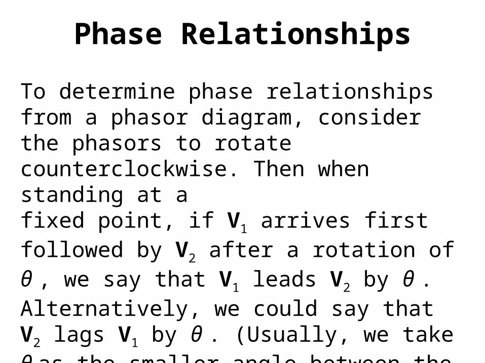
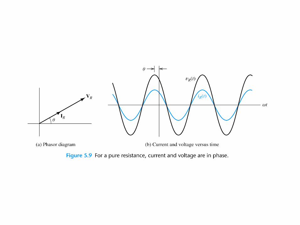
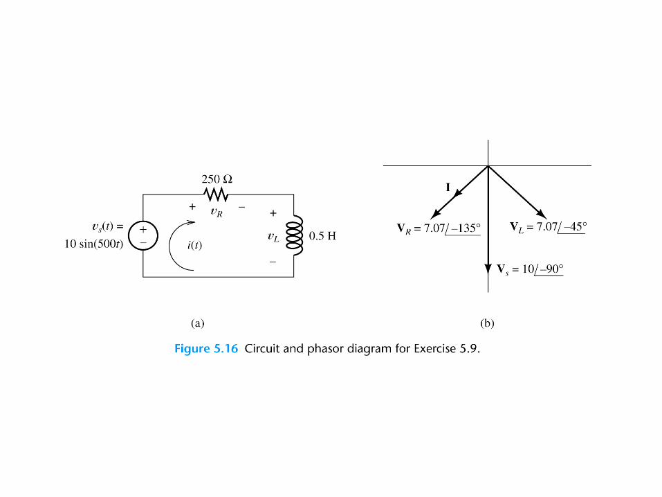
Phase Relationships
To determine phase relationships from a phasor diagram, consider the phasors to rotate counterclockwise. Then when standing at afixed point, if V1 arrives first followed by V2 after a rotation of θ , we say that V1 leads V2 by θ . Alternatively, we could say that V2 lags V1 by θ . (Usually, we take θ as the smaller angle between the two phasors.)
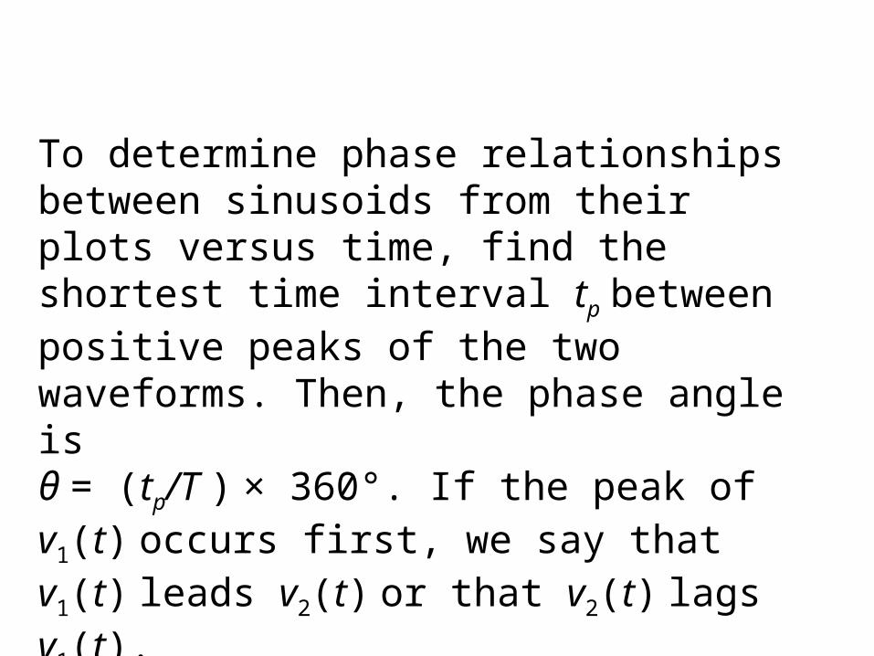
To determine phase relationships between sinusoids from their plots versus time, find the shortest time interval tp between positive peaks of the two waveforms. Then, the phase angle isθ = (tp/T ) × 360°. If the peak of v1(t) occurs first, we say that v1(t) leads v2(t) or that v2(t) lags v1(t).


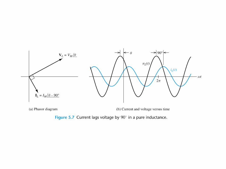

COMPLEX IMPEDANCES
LL Lj IV
90 LLjZ L
LLL Z IV


CCC Z IV
90111
CCjC
jZC
RR RIV


Kirchhoff’s Laws in Phasor Form
We can apply KVL directly to phasors. The sum of the phasor voltages equals zero for any closed path.The sum of the phasor currents entering a node must equal the sum of the phasor currents leaving.
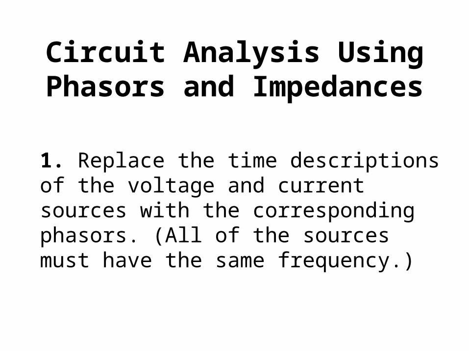
Circuit Analysis Using Phasors and Impedances
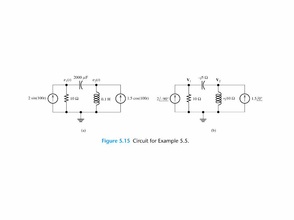
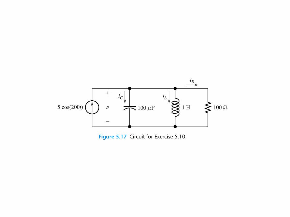
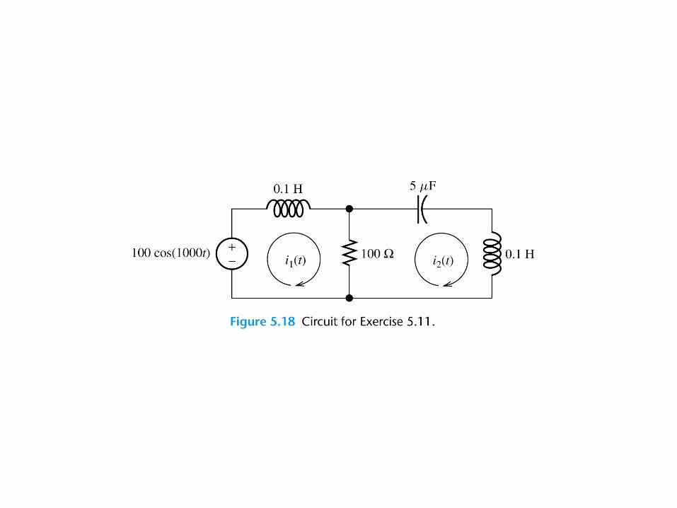
1. Replace the time descriptions of the voltage and current sources with the corresponding phasors. (All of the sources must have the same frequency.)
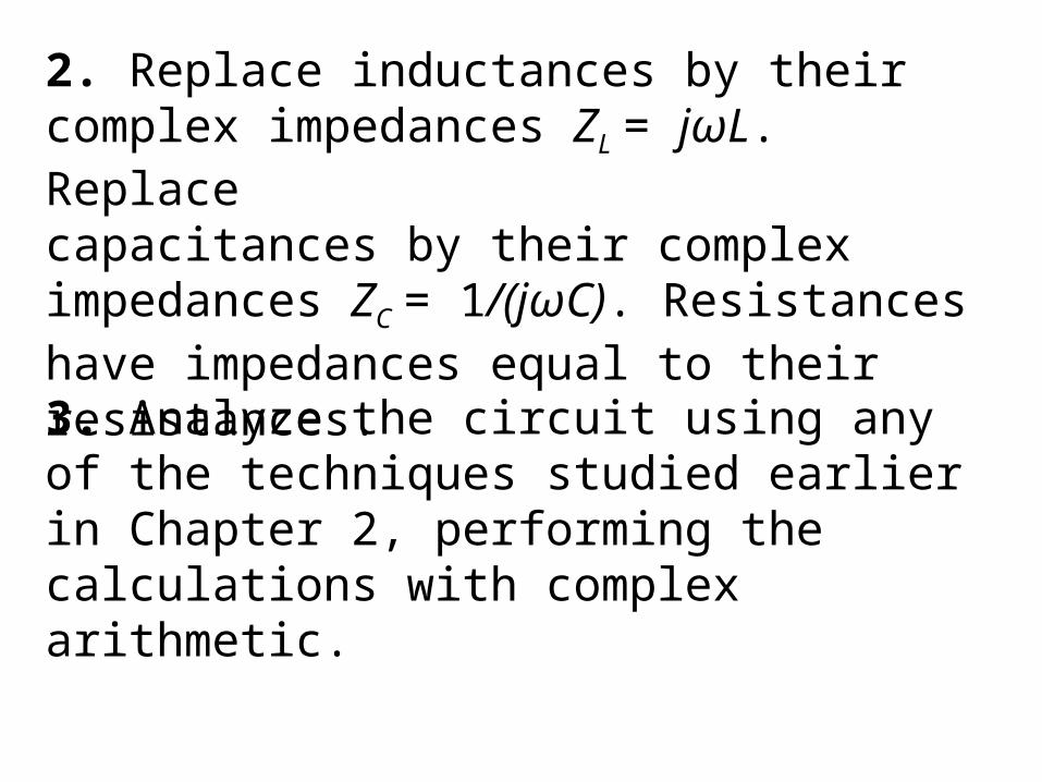
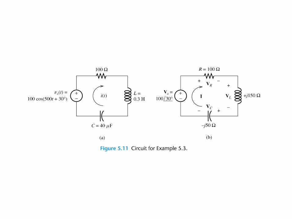
2. Replace inductances by their complex impedances ZL = jωL. Replacecapacitances by their complex impedances ZC = 1/(jωC). Resistances have impedances equal to their resistances.3. Analyze the circuit using any of the techniques studied earlier in Chapter 2, performing the calculations with complex arithmetic.


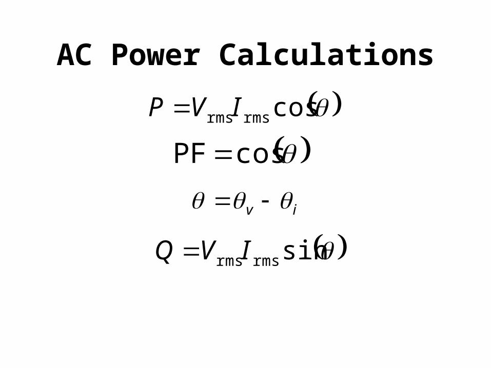
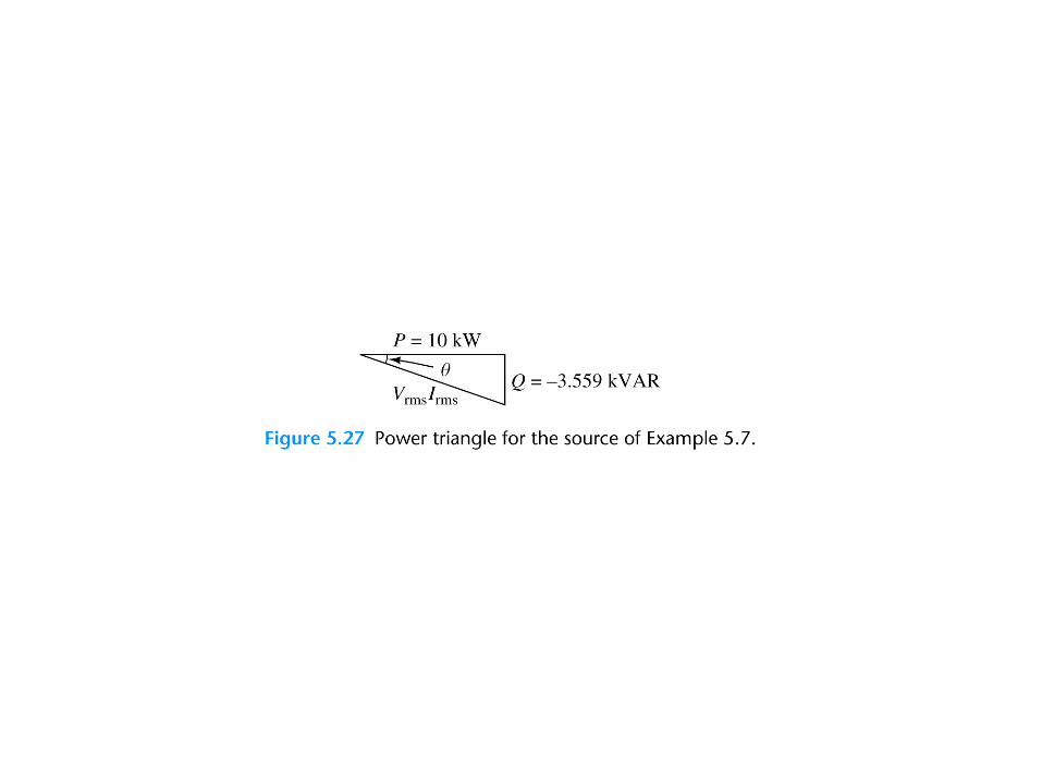
AC Power Calculations
cosrmsrmsIVP
cosPF
iv
sinrmsrmsIVQ

rmsrmspower apparent IV
2rmsrms
22 IVQP
RIP 2rms
XIQ 2rms
R
VP R
2rms
X
VQ X
2rms


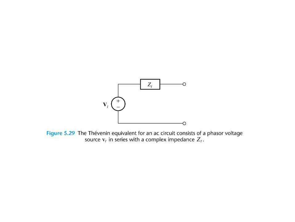
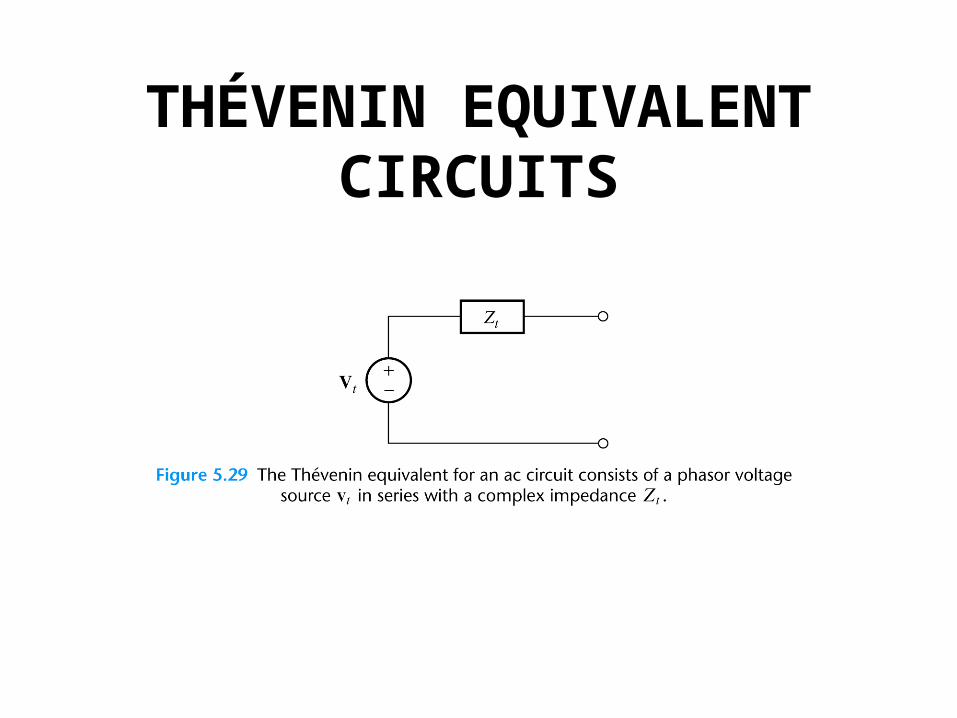
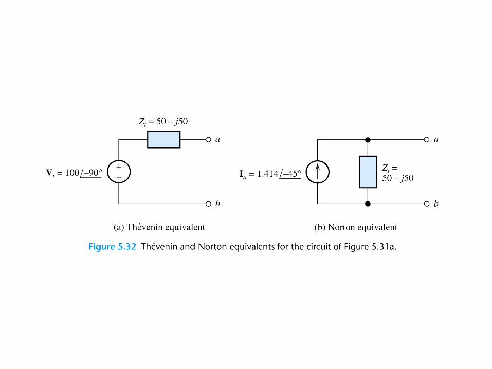
THÉVENIN EQUIVALENT CIRCUITS
The Thévenin voltage is equal to the open-circuit phasor voltage of the original circuit.
ocVV t
We can find the Thévenin impedance by zeroing the independent sources and determining the impedance looking into the circuit terminals.
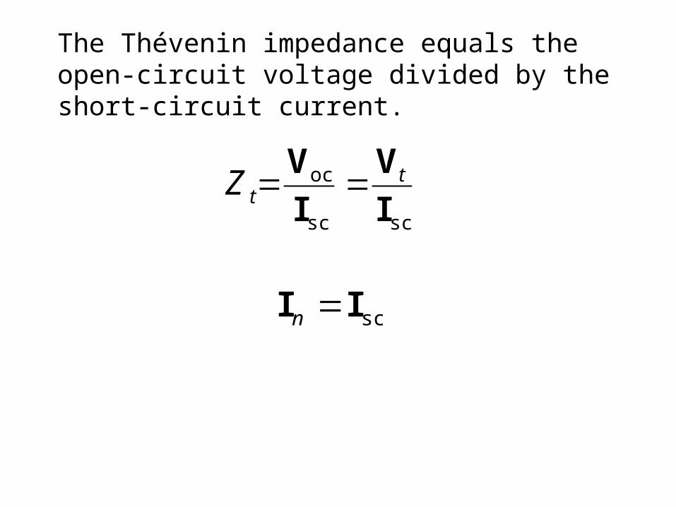
The Thévenin impedance equals the open-circuit voltage divided by the short-circuit current.
scsc
oc
I
V
I
V ttZ
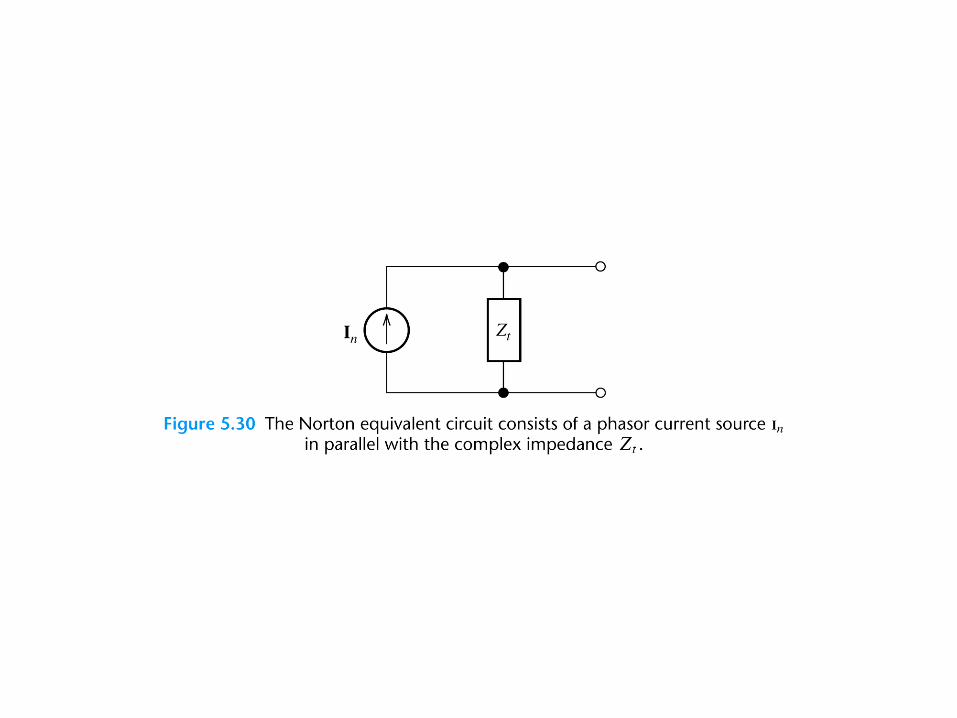
scII n


Maximum Power TransferIf the load can take on any complex
value, maximum power transfer is attained for a load impedance equal to the complex conjugate of the Thévenin impedance.If the load is required to be a pure resistance, maximum power transfer is attained for a load resistance equal to the magnitude of the Thévenin impedance.

Related Documents