1 UOIT Faculty of Engineering and Applied Science Winter Semester 2007 ENGR3930U - HEAT TRANSFER Steady Heat Conduction Drs. Ibrahim Dincer & Mehmet Kanoglu

Welcome message from author
This document is posted to help you gain knowledge. Please leave a comment to let me know what you think about it! Share it to your friends and learn new things together.
Transcript

1
UOITFaculty of Engineering and Applied Science
Winter Semester 2007
ENGR3930U-HEAT TRANSFER
Steady Heat Conduction
Drs. Ibrahim Dincer & Mehmet Kanoglu

Chapter 3STEADY HEAT CONDUCTION
M. Kanoglu, Y. Pelez
Copyright © The McGraw-Hill Companies, Inc. Permission required for reproduction or display.
Heat and Mass Transfer, 3rd EditionYunus A. Cengel
McGraw-Hill, New York, 2007

OUTLINE
• Steady Heat Conduction in Plane Walls• Thermal Contact Resistance• Generalized Thermal Resistance Networks• Heat Conduction in Cylinders and Spheres• Critical Radius of Insulation• Heat Transfer from Finned Surfaces• Heat Transfer in Common Configurations• Conclusions
3

4
Heat transfer in a certain directionis driven by the temperaturegradient in that direction.
There will be no heat transfer in adirection in which there is nochange in temperature.
Steady Heat Conduction In Plane Walls
If the air temperatures in andoutside the house remain constant,then heat transfer through the wallof a house can be modeled as steadyand one-dimensional.
Heat transfer through the wall is inthe normal direction to the wallsurface, and no significant heattransfer takes place in the wall inother directions.

5
Integrating and rearranging
or
for steady operation (no change in the temperature of the wall with time at any point) and
• Energy balance:
• The Fourier’s law of heat conduction for the wall:
where dT/dx= constant and T varies linearly with x.
6
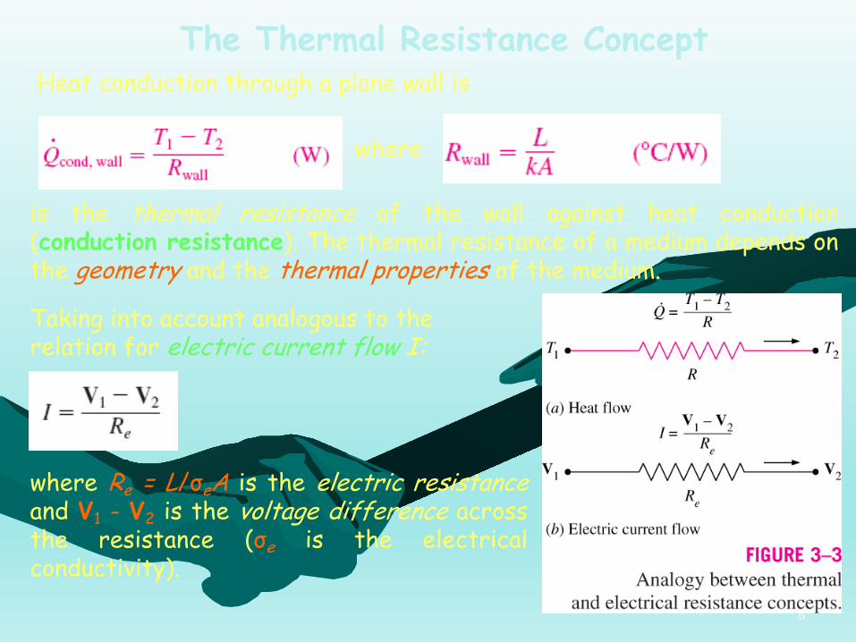
The Thermal Resistance ConceptHeat conduction through a plane wall is
where
is the thermal resistance of the wall against heat conduction(conduction resistance). The thermal resistance of a medium depends onthe geometry and the thermal properties of the medium.
Taking into account analogous to the relation for electric current flow I:
where Re = L/σeA is the electric resistanceand V1 - V2 is the voltage difference acrossthe resistance (σe is the electricalconductivity).

7
Newton’s law of cooling for convection heat transfer rate:
can be rearranged as
with
which is the thermal resistance of thesurface against heat convection, or simplythe convection resistance of the surface.
When the convection heat transfercoefficient is very large , theconvection resistance becomes zero and. . That is, the surface offers noresistance to convection, and thus it doesnot slow down the heat transfer process.

8
The rate of radiation heat transfer between a surface of emissivity εand area As at temperature Ts and the surrounding surfaces at someaverage temperature Tsurr can be expressed as
with which is the radiation resistance.
is the radiation heat transfer coefficient.Both Ts and Tsurr must be in K in the evaluation of hrad.When , the radiation effect can properly be accounted for by replacing h in the convection resistance relation by
where hcombined is the combined heat transfer coefficient.

9
Thermal Resistance Network

10
Under steady conditions
which can be rearranged as
or
Adding the numerators and denominators yields
where
The thermal resistances are in series, and the equivalent thermalresistance is determined by simply adding the individual resistances,just like the electrical resistances connected in series.

11
The equation can be rearranged as
Here, the temperature drop across any layer is equal to the rate ofheat transfer times the thermal resistance across that layer.
12
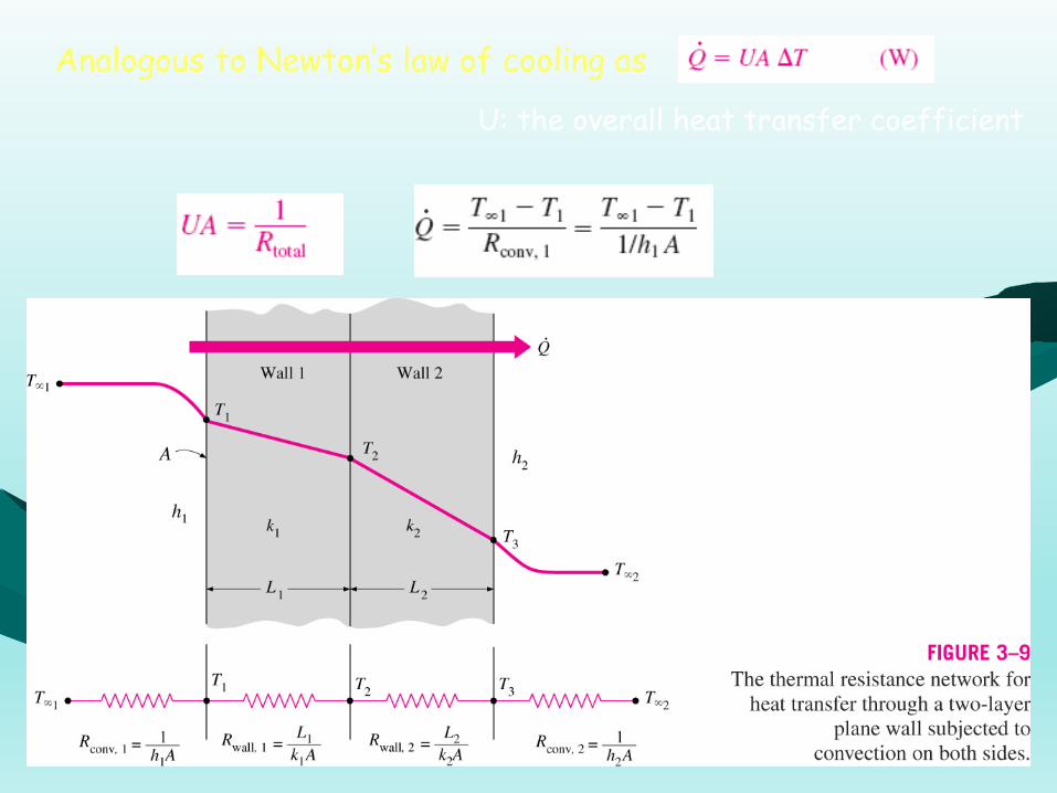
Analogous to Newton’s law of cooling as
U: the overall heat transfer coefficient

13
Multilayer Plane WallsThe rate of steady heat transfer through aplane wall consisting of two layers
Rtotal: the total thermal resistance
for the resistances in series.
F It is limited to systems involving steadyheat transfer with no heat generation.
14

15

16
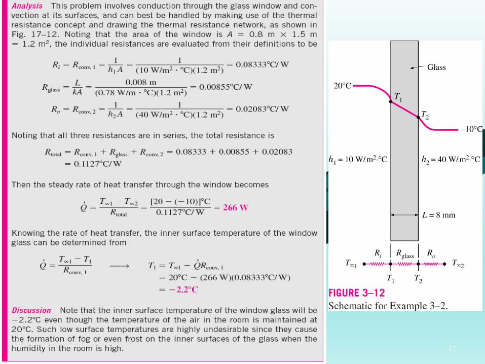
17
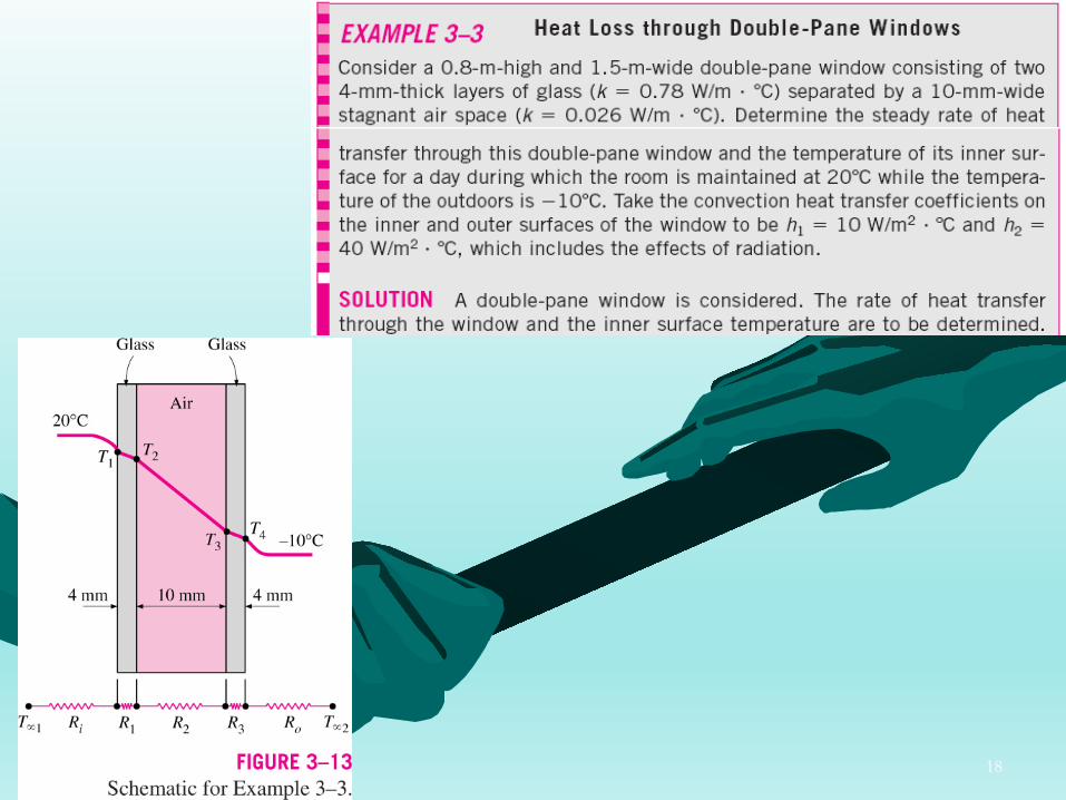
18

19

20
THERMAL CONTACT RESISTANCE
Thermal Contact Resistance (Rc.): the resistance per unit interface area
In the analysis of heat conduction through multilayer solids, weassumed “perfect contact” at the interface of two layers, and thus notemperature drop at the interface.

21
Heat transfer through the interfaceof two metal rods of cross-sectionalarea A is the sum of the heattransfers through the solid contactspots and the gaps in the noncontactareas and can be expressed as
An analogous manner to Newton’s law of cooling:
A: the apparent interface area(which is the same as the cross-sectional area of the rodsTinterface: the effective temperaturedifference at the interface

22
The thermal contact conductance is expressed as
It is related to thermal contact resistance by
The thermal resistance of a 1-cm-thick layer of an insulating material per unit surface area is
whereas for a 1-cm-thick layer of copper, it is

23

24
The thermal contact conductance is highest (with the lowest contactresistance) for soft metals with smooth surfaces at high pressure.

25

26

27

28

29
GENERALIZED THERMAL RESISTANCE NETWORKS
With the electrical analogy
For the composite wall consisting oftwo parallel layers, the total heattransfer is the sum of the heattransfers through each layer.
with
30
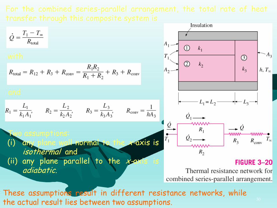
For the combined series-parallel arrangement, the total rate of heattransfer through this composite system is
with
and
Two assumptions:(i) any plane wall normal to the x-axis is
isothermal and(ii) any plane parallel to the x-axis is
adiabatic.
These assumptions result in different resistance networks, whilethe actual result lies between two assumptions.
31
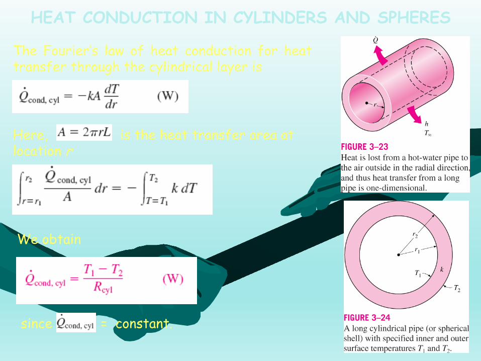
The Fourier’s law of heat conduction for heattransfer through the cylindrical layer is
Here, is the heat transfer area at location r
We obtain
since = constant.
HEAT CONDUCTION IN CYLINDERS AND SPHERES

32
The thermal resistance of the cylindrical layer against heatconduction, or simply the conduction resistance of the cylinder layer.
Repeating the analysis for a spherical layer by taking
with
which is the thermal resistance of the spherical layer against heatconduction, or simply the conduction resistance of the sphericallayer.
33
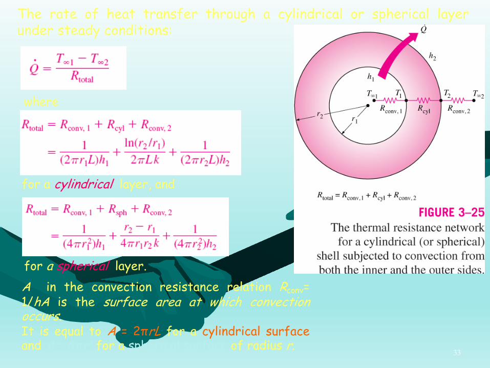
The rate of heat transfer through a cylindrical or spherical layerunder steady conditions:
where
for a cylindrical layer, and
for a spherical layer.A in the convection resistance relation Rconv=1/hA is the surface area at which convectionoccurs.It is equal to A = 2πrL for a cylindrical surfaceand A = 4πr2 for a spherical surface of radius r.

34
Multilayered Cylinders and SpheresSteady heat transfer through multilayered cylindrical or sphericalshells is treated like multilayered plane walls.

35
Rtotal is the total thermal resistance, expressed as
Here, A1 = 2 πr1L and A4 = 2 πr4L
The total thermal resistance issimply the arithmetic sum of theindividual thermal resistances in thepath of heat flow
We can also calculate T2 from
36

37

38

39

40

41
CRITICAL RADIUS OF INSULATIONThe rate of heat transfer from the insulated pipe to the surrounding air is
Performing the differentiation and solvingfor r2 yields the critical radius of insulationfor a cylindrical body to be
The critical radius of insulation for a sphericalshell is
k : the thermal conductivity of the insulationh : the convection heat transfer coefficient on the
outer surface

42
43

44

45
HEAT TRANSFER FROM FINNED SURFACESThe rate of heat transfer from a surface at a temperature Ts to the surrounding medium at T is given by Newton’s law of cooling as
As : the heat transfer surface areah : the convection heat transfer coefficient
There are two ways to increase the rate of heat transfer:1) to increase the convection heat transfer coefficient h 2) to increase the surface area As
Increasing h may require the installation of a pump or fan, or replacingthe existing one with a larger one, but this approach may or may notbe practical. Besides, it may not be adequate.
The alternative is to increase the surface area by attaching to thesurface extended surfaces called fins made of highly conductivematerials such as aluminum.

46
Consider steady operation with no heat generation in the fin with the following assumptions:
• The thermal conductivity k of thematerial remains constant.• The convection heat transfercoefficient h is constant and uniformover the entire surface of the fin forconvenience in the analysis.

47
Fin EquationUnder steady conditions, the energy balance on this volume elementcan be expressed as
or
with
Substituting and dividing by Δx, we obtain
Taking the limit as Δx → 0 gives

48
From Fourier’s law of heat conduction we have
where Ac : the cross-sectional area of the fin at location x
In the special case (with constant cross section and thermal conductivity):
and is the temperature excess. At the fin base we have .
with
The function u and its second derivative must be constant multiples of each other.
where C1 and C2 are arbitrary constants.

49
Infinitely Long Fin (Tfin tip = T∞)For a sufficiently long fin of uniform cross section (Ac constant):
p : the perimeterAc : the cross-sectional area of the fin x : the distance from the fin base

50
Negligible Heat Loss from the Fin Tip (Insulated fin tip, )
The fin tip can be assumed to be insulated, and the condition at the fin tip can be expressed as
The rate of heat transfer from the fin can be determined again from Fourier’s law of heat conduction:
The heat transfer relations for the very long fin and the fin withnegligible heat loss at the tip differ by the factor tanh aL, whichapproaches 1 as L becomes very large.
51
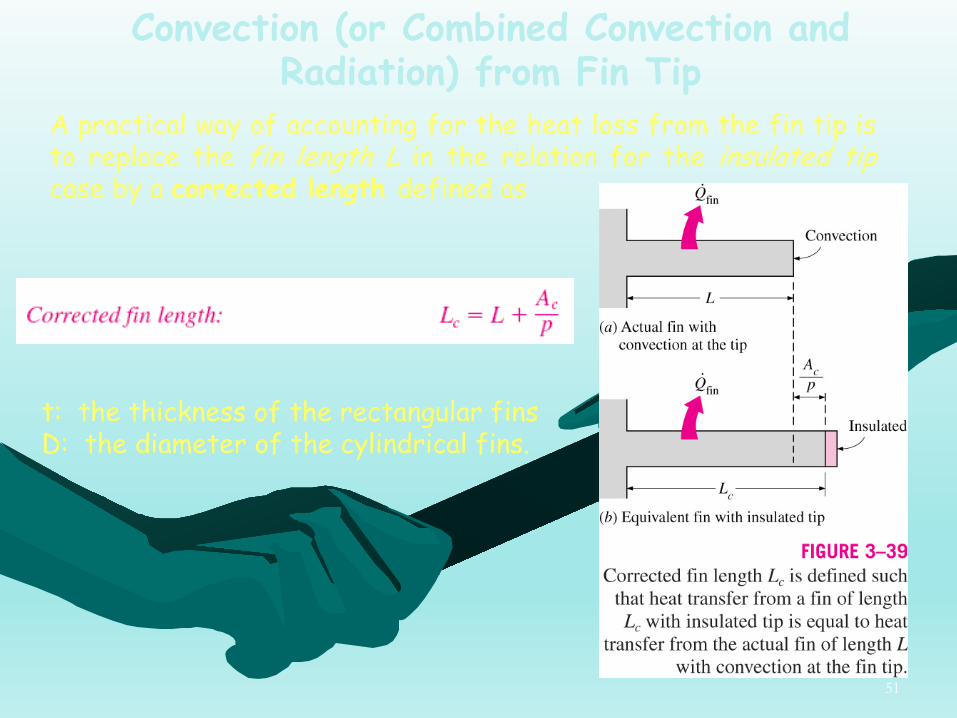
Convection (or Combined Convection and Radiation) from Fin Tip
A practical way of accounting for the heat loss from the fin tip isto replace the fin length L in the relation for the insulated tipcase by a corrected length defined as
t: the thickness of the rectangular finsD: the diameter of the cylindrical fins.
52
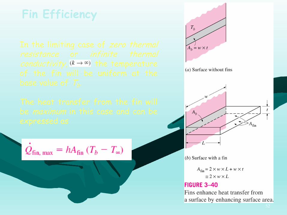
Fin Efficiency
In the limiting case of zero thermalresistance or infinite thermalconductivity, the temperatureof the fin will be uniform at thebase value of Tb.
The heat transfer from the fin willbe maximum in this case and can beexpressed as

53
Fin efficiency can be defined as:
or
For the cases of constant cross section ofvery long fins and fins with insulated tips,the fin efficiency can be expressed as
and
since Afin = pL for fins with constant cross section.
54

55
56
• Fins with triangular and parabolic profiles contain less material andare more efficient than the ones with rectangular profiles, andthus are more suitable for applications requiring minimum weightsuch as space applications.
• An important consideration in the design of finned surfaces is theselection of the proper fin length L. Normally the longer the fin,the larger the heat transfer area and thus the higher the rate ofheat transfer from the fin.
• The larger the fin, the bigger the mass, the higher the price, andthe larger the fluid friction. Therefore, increasing the length ofthe fin beyond a certain value cannot be justified unless the addedbenefits outweigh the added cost.
• Fin lengths that cause the fin efficiency to drop below 60%percent usually cannot be justified economically and should beavoided. The efficiency of most fins used in practice is above 90%.
57
58
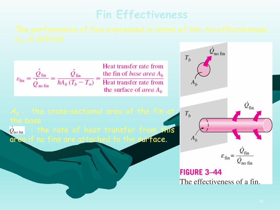
Fin EffectivenessThe performance of fins expressed in terms of the fin effectiveness εfin is defined
Ab : the cross-sectional area of the fin atthe base
: the rate of heat transfer from thisarea if no fins are attached to the surface.

59
An effectiveness of εfin= 1 indicates that the addition of fins to the surface does not affect heat transfer at all.
An effectiveness of εfin < 1 indicates that the fin actually acts asinsulation, slowing down the heat transfer from the surface.
An effectiveness of εfin > 1 indicates that fins are enhancing heattransfer from the surface, as they should.
Finned surfaces are designed on the basis of maximizingeffectiveness for a specified cost or minimizing cost for a desiredeffectiveness.
The fin efficiency and fin effectiveness are related to each other by

60
The effectiveness of a sufficiently long fin of uniform cross section under steady conditions is determined to be
since Ac = Ab.
In the design and selection of the fins, the following should be takeninto account:
• The thermal conductivity k of the fin material should be as high aspossible. Thus it is no coincidence that fins are made from metals,with copper, aluminum, and iron being the most common ones. Perhapsthe most widely used fins are made of aluminum because of its lowcost and weight and its resistance to corrosion.
• The ratio of the perimeter to the cross-sectional area of the finp/Ac should be as high as possible. This criterion is satisfied by thinplate fins and slender pin fins.
• The use of fins is most effective in applications involving a lowconvection heat transfer coefficient.

61
The rate of heat transfer for a surface containing n fins can beexpressed as
The overall effectiveness for a finnedsurface is defined as the ratio of thetotal heat transfer from the finnedsurface to the heat transfer from thesame surface if there were no fins.
Ano fin : the area of the surface when there are no fins
Afin : the total surface area of all the fins on the surface
Aunfin : the area of the unfinned portion of the surface

62
Proper Length of a FinTo get a sense of the proper length of a fin,we compare heat transfer from a fin of finitelength to heat transfer from an infinitely longfin under the same conditions. The ratio ofthese two heat transfers is
Studies have shown that the error involvedin one-dimensional fin analysis is negligible(less than about 1%) when
The heat transfer performance of heat sinks is usually expressed in terms of their thermal resistances R in oC/W, which is defined as

63

64
65

66

67
68
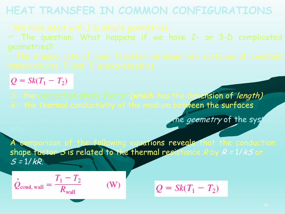
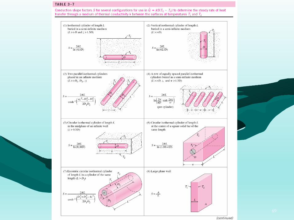
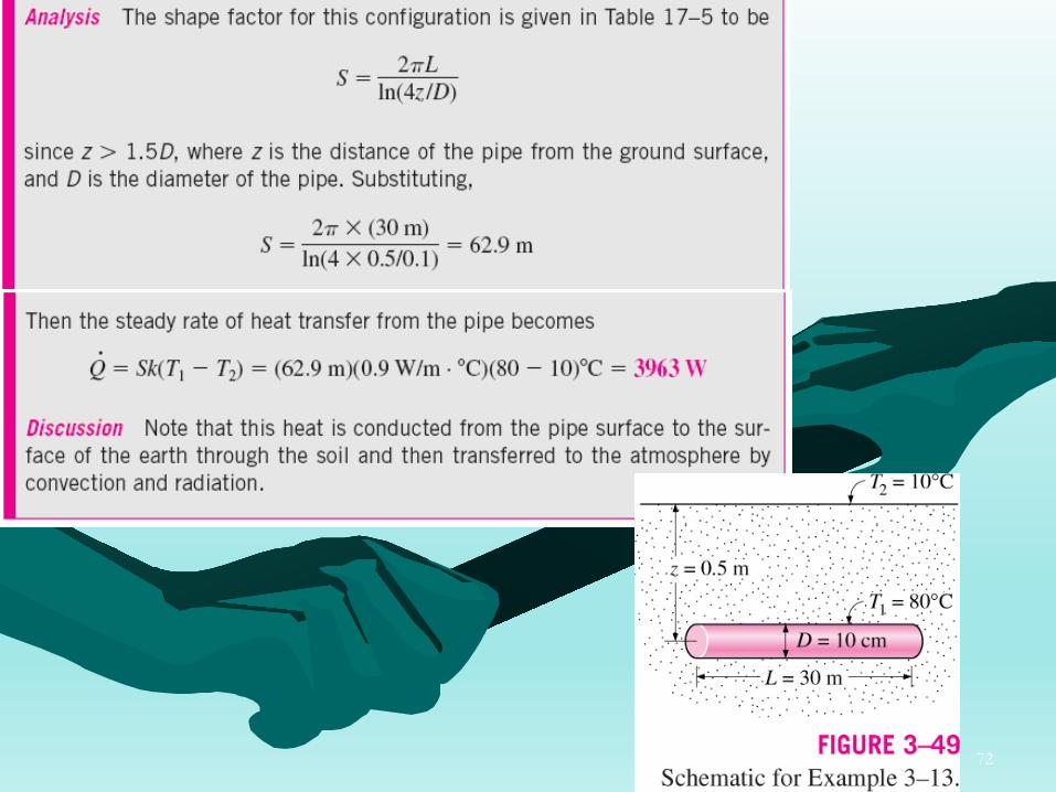
HEAT TRANSFER IN COMMON CONFIGURATIONS• We have dealt with 1-D simple geometries.F The question: What happens if we have 2- or 3-D complicatedgeometries?• The steady rate of heat transfer between two surfaces at constanttemperatures T1 and T2 is expressed as
S : the conduction shape factor (which has the dimension of length) k : the thermal conductivity of the medium between the surfaces
F The conduction shape factor depends on the geometry of the system only.A comparison of the following equations reveals that the conductionshape factor S is related to the thermal resistance R by R = 1/kS orS = 1/kR.
69

70

71
72

Concluding Points:
73
• Steady and One-Dimensional Modeling of Heat Transfer through a Wall• Conduction and Convection Resistances• Analogy between Thermal and Electrical Resistances• Radiation and Combined Heat Transfer Coefficients• Overall Heat Transfer Coefficient• Heat Transfer through a Plane and Multilayer Plane Walls• Thermal Contact Resistance• Generalized Thermal Resistance Networks• Heat Conduction in Multilayered Cylinders and Spheres• Critical Radius of Insulation for Cylindrical and Spherical Bodies• Heat Transfer from Finned Surfaces• Fin Efficiency, Fin Effectiveness and Overall Effectiveness• Important Considerations in the Design and Selection of Fins• Heat Transfer in Common Configurations and Conduction Shape Factors
Related Documents