Dati Tecnici Technical Data Sheet 19_07_2017 Euro fire MEFA Italia SpA Fissaggio & Supporto di Impianti Tel. +39 02 93540195 - Fax. +39 02 93543208 - www.mefaitalia.com Rev. nr. 0 A02 doc. nr. A02001A Stazione di Allarme ad Umido modelli E-D-B Diametro nominale Dimensioni Perdita di carico in mt/tubo Peso unitario Codice Valvola Codice Trim A B C D s/trim con trim Poll. DN [mm] [mm] [mm] [mm] [kg/pz] [kg/pz] 4 100 700 286 390 700 3,8 19 23 AVE40 AVTRIM40VAP 6 150 700 286 390 700 10 23 30 AVE60 AVTRIM60VAP APPROVED For Listing/Approval Details and Limitations contact MEFA Sales Representative. Valvola modello E scanalata/scanalata Diametro nominale Dimensioni Perdita di carico in mt/tubo Peso unitario Codice Valvola Codice Trim A B C D s/trim con trim Poll. DN [mm] [mm] [mm] [mm] [kg/pz] [kg/pz] 4 100 700 264 350 700 3,8 23 30 AVD40 AVTRIM40VAP 6 150 700 287 350 700 10,0 29 36 AVD60 AVTRIM60VAP 8 200 700 335 520 700 10,5 57 64 AVD80 AVTRIM80VAP Valvola modello D flangiata/scanalata Diametro nominale Dimensioni Perdita di carico in mt/tubo Peso unitario Codice Valvola Codice Trim A B C D s/trim con trim Poll. DN [mm] [mm] [mm] [mm] [kg/pz] [kg/pz] 3 80 700 273 390 700 1,0 23 30 AVB30 AVTRIM30VAP 4 100 700 226 390 700 3,8 25 32 AVB40 AVTRIM40VAP 6 150 700 264 390 700 10,0 34 42 AVB60 AVTRIM60VAP 8 200 700 298 520 700 10,5 59 66 AVB80 AVTRIM80VAP Valvola modello B flangiata/flangiata Caratteristiche: Stazione disponibile con trim sfuso oppure montato e collaudato in officina Trim a pressione costante; per trim a pressione variabile ordinare la Camera di Ritardo Modello E fornita separatamente • Materiale Corpo valvola in ghisa sferoidale Otturatore in ghisa grigia Guarnizione otturatore gomma EPDM Sede otturatore in ottone scanalato Molle in acciaio inossidabile • Finitura Corpo valvola smaltato nero esternamente con scanalatura zincata Corpo valvola compatto, leggero e resistente • Flangiatura valvole: PN16 • Pressione di esercizio: 12bar 175psi A B C D Stazione ad Umido Vista frontale Vista laterale Camera di ritardo Descrizione Peso unitario [kg/pz] Codice Per sistemi a Pressione Variabile (Pompe automatiche) 9,0 RETARD Camera di ritardo modello E Page/Pagina 1 of/di 6

Welcome message from author
This document is posted to help you gain knowledge. Please leave a comment to let me know what you think about it! Share it to your friends and learn new things together.
Transcript
Dati TecniciTechnical Data Sheet
19_07_2017
Euro fire
MEFA Italia SpA Fissaggio & Supporto di Impianti Tel. +39 02 93540195 - Fax. +39 02 93543208 - www.mefaitalia.com
Rev. nr. 0
A02
doc. nr. A02001A
Stazione di Allarme ad Umido modelli E-D-B
Diametro nominale
Dimensioni Perdita di caricoin mt/tubo
Peso unitario Codice Valvola
CodiceTrimA B C D s/trim con trim
Poll. DN [mm] [mm] [mm] [mm] [kg/pz] [kg/pz]
4 100 700 286 390 700 3,8 19 23 AVE40 AVTRIM40VAP
6 150 700 286 390 700 10 23 30 AVE60 AVTRIM60VAP
APPROVED For Listing/Approval Details and Limitations
contact MEFA Sales Representative.
Valvola modello E scanalata/scanalata
Diametro nominale
Dimensioni Perdita di caricoin mt/tubo
Peso unitario Codice Valvola
CodiceTrimA B C D s/trim con trim
Poll. DN [mm] [mm] [mm] [mm] [kg/pz] [kg/pz]
4 100 700 264 350 700 3,8 23 30 AVD40 AVTRIM40VAP
6 150 700 287 350 700 10,0 29 36 AVD60 AVTRIM60VAP
8 200 700 335 520 700 10,5 57 64 AVD80 AVTRIM80VAP
Valvola modello D fl angiata/scanalata
Diametro nominale
Dimensioni Perdita di caricoin mt/tubo
Peso unitario Codice Valvola
CodiceTrimA B C D s/trim con trim
Poll. DN [mm] [mm] [mm] [mm] [kg/pz] [kg/pz]
3 80 700 273 390 700 1,0 23 30 AVB30 AVTRIM30VAP
4 100 700 226 390 700 3,8 25 32 AVB40 AVTRIM40VAP
6 150 700 264 390 700 10,0 34 42 AVB60 AVTRIM60VAP
8 200 700 298 520 700 10,5 59 66 AVB80 AVTRIM80VAP
Valvola modello B fl angiata/fl angiata
Caratteristiche:
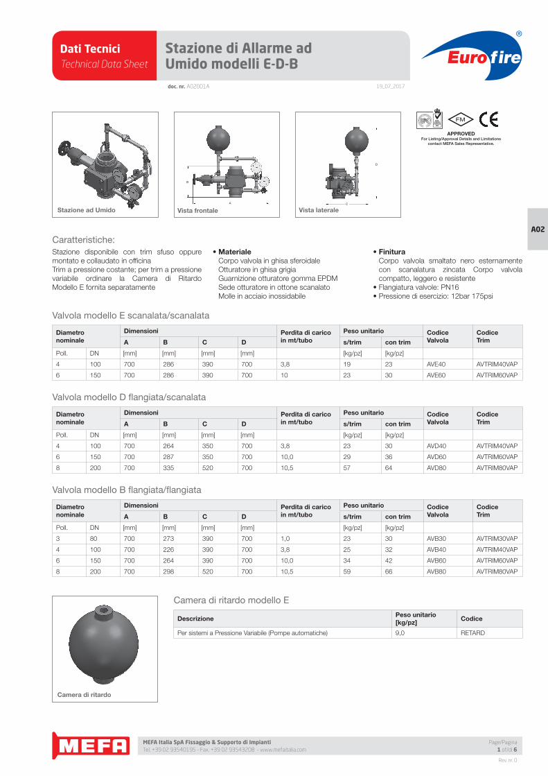
Stazione disponibile con trim sfuso oppure
montato e collaudato in offi cina
Trim a pressione costante; per trim a pressione
variabile ordinare la Camera di Ritardo
Modello E fornita separatamente
• Materiale Corpo valvola in ghisa sferoidale
Otturatore in ghisa grigia
Guarnizione otturatore gomma EPDM
Sede otturatore in ottone scanalato
Molle in acciaio inossidabile
• Finitura Corpo valvola smaltato nero esternamente
con scanalatura zincata Corpo valvola
compatto, leggero e resistente
• Flangiatura valvole: PN16
• Pressione di esercizio: 12bar 175psi
A
B
C
D
Stazione ad Umido Vista frontale Vista laterale
Camera di ritardo
DescrizionePeso unitario[kg/pz]
Codice
Per sistemi a Pressione Variabile (Pompe automatiche) 9,0 RETARD
Camera di ritardo modello E
Page/Pagina1 of/di 6
Dati TecniciTechnical Data Sheet
19_07_2017
Euro fire
MEFA Italia SpA Fissaggio & Supporto di Impianti Tel. +39 02 93540195 - Fax. +39 02 93543208 - www.mefaitalia.com
Rev. nr. 0
A02
Page/Pagina2 of/di 6
doc. nr. A02001A
Stazione di Allarme ad Umido modelli E-D-B
Descrizione
Le Valvole di Allarme ad Umido modello E, D e B comprendono un
otturatore di ghisa a battente con la guarnizione di tenuta in gomma
che appoggia su una sede di ottone scanalata. La sede ha la superfi cie
di contatto stagnata per evitare l’incollaggio della guarnizione sul piano
di appoggio. Un tubazione di by-pass esterna permette di trasferire un
aumento della pressione dell’acqua a monte verso l’impianto a valle e di
costituire una surpressione che facilita poi il mantenimento della chiusura
dell’otturatore.
Un più forte aumento di pressione solleverà l’otturatore immettendo
l’acqua nella camera di ritardo.
La Camera di Ritardo modello E collega la scanalatura nella sede
dell’otturatore con la tubazione dell’allarme e gli apparecchi serviti
come l’interruttore elettrico di allarme e la campana a motore idraulico.
Degli speciali orifi zi tarati posti nella tubazione dell’allarme permettono il
rapido svuotamento della camera di ritardo evitando dei falsi allarmi.
Funzionamento
Quando un erogatore sprinkler oppure la valvola di prova dell’allarme
vengono aperti la pressione sull’impianto a valle della valvola diminuisce
rispetto alla pressione a monte della valvola (lato alimentazione).
L’otturatore si solleva dalla propria sede spinto dalla maggiore pressione a
monte e permette all’acqua di entrare nell’impianto per la sua erogazione
sull’incendio. Parte dell’acqua entra nella scanalatura della sede, percorre
la tubazione dell’allarme fi no alla camera di ritardo (se installata) ed arriva
agli apparecchi di allarme. Dei colpi di ariete momentanei nella rete di
alimentazione provocano il distacco intermittente dell’otturatore dalla
sede e dei falsi allarmi. Le valvole di allarme modello E, D e B prevengono
questi falsi allarmi in due modi:
a. Il by-pass esterno provvisto di una valvola di non ritorno permette
a questi colpi di ariete di accumulare pressione nell’impianto a valle:
questo provoca un eccesso di pressione sul lato a valle che mantiene
chiuso l’otturatore. Nel caso in cui l’otturatore venisse comunque
alzato entra in azione la camera di ritardo.
b. La camera di ritardo comprende due orifi zi tarati per l’ingresso e lo
scarico dell’acqua che permettono all’apparecchio di svuotarsi prima
di essere interamente riempito e di azionare gli allarmi. La camera
di ritardo comprende al suo ingresso un fi ltro che evita l’otturazione
dell’orifi zio tarato.
Si deve essere certi che le valvole di ritegno sul trim siano dirette nella
loro giusta direzione come indicato dalla freccia ricavata sulla fusione. La
freccia nella valvola di ritegno di ¾” nel by-pass deve essere diretta verso
la valvola di allarme mentre quella sulla valvola di ½” nello scarico della
camera di ritardo deve essere diretta verso l’imbuto di scarico.
Manutenzione
Le valvole di allarme modello E, D e B non necessitano di alcuna
regolazione ed in condizioni normali di utilizzo richiedono il minimo
di manutenzione. I due manometri nel trim della valvola dovrebbero
indicare due valori di pressione diversi: pressione più alta nell’impianto
(manometro superiore) e più bassa nella tubazione di alimentazione
(manometro inferiore). Nel caso invece che i valori segnati dai due
manometri siano uguali e presumendo che nei giorni precedenti non si
siano aperte valvole di drenaggio o di prova allora è possibile che ci sia
un trafi lamento in qualche parte della stazione di allarme e che impedisce
di trattenere l’eccesso di pressione a valle della valvola di allarme. In
questo caso occorre verifi care che tutte le valvole normalmente chiuse
siano chiuse a fondo, che non vi siano perdite d’acqua per la frattura di
qualche raccordo nella rete di tubazioni. Se non vi sono ragioni visibili per
la perdita di pressione è possibile che la guarnizione dell’otturatore sia
danneggiata e da sostituire. Una guarnizione danneggiata è anche uno
dei motivi principali che provocano i falsi allarmi e la sua sostituzione in
genere elimina questo difetto.
Questa sostituzione può rendersi necessaria di tanto in tanto ed una
nuova guarnizione può essere richiesta al distributore. Quando questo
deve essere fatto si deve procedere in questo modo:
1. Notifi care la compagnia di assicurazione che l’impianto dovrà essere
messo temporaneamente fuori servizio.
2. Chiudere la valvola principale di intercettazione dell’impianto
(saracinesca o valvola a farfalla o valvola interrata esterna) mettendo
di guardia una persona con l’incarico di riaprire la valvola appena
terminato il lavoro.
3. Aprire la valvola principale di scarico da 2” (da 1.1/2” sull’impianto di
3”) e svuotare completamente l’impianto.
4. Aprire anche la valvola terminale di prova installata sull’impianto
sprinkler e le eventuali valvole di scarico di zona per ventilare le
tubazioni.
5. Dopo che la pressione è stata eliminata in tutte le tubazioni si può
smontare la fl angia di ispezione della valvola di allarme per verifi care lo
stato della guarnizione e della sede dell’otturatore rimuovendo scorie
ed altro materiale solido eventualmente presente nella scanalatura.
6. Pulire il piano di appoggio dell’otturatore con un panno pulito.
7. Sostituire la guarnizione dell’otturatore.
8. Il complesso dell’otturatore può essere estratto dalla valvola svitando
i due tappi che permetteranno l’estrazione del perno di rotazione.
9. Ricollocare il complesso dell’otturatore e verifi care che anche
la guarnizione del coperchio di ispezione sia in buono stato ed
eventualmente sostituirla.
10. Richiudere tutte le valvole di drenaggio che erano state aperte ma
non ancora la valvola terminale di prova dell’allarme.
11. Per evitare l’intervento degli allarmi mentre si ricarica l’impianto
chiudere le due valvole da ½” di prova e di intercettazione dell’allarme
presenti nel trim.
12. Aprire lentamente la valvola principale di intercettazione dell’impianto
riportando in pressione la rete di tubazioni. Un carico lento impedisce
alla eventuale sporcizia delle tubazioni interrate di entrare nella valvola di
allarme. Durante questa operazione l’otturatore della valvola rimarrà aperto
e si chiuderà da solo quando l’impianto si sarà portato alla sua pressione
normale.
13. Chiudere la valvola terminale di prova quando il getto d’acqua non
trasporta più delle sacche d’aria indicando che la maggior parte
dell’aria presente nei tubi è stata estratta.
14. Quando l’impianto ha raggiunto la pressione operativa ed il presso-
stato a valle segna una pressione maggiore di quello a monte la
valvola principale può essere aperta completamente e sigillata.
15. Aprire solo la valvola da ½” di tacitazione dell’allarme e sigillarla
aperta. Se questa valvola rimane chiusa non sarà possibile segnalare
l’allarme di incendio.
16. Per provare l’allarme aprire l’altra valvola di prova da ½” nel by-
pass del trim. Questa valvola riceve l’acqua in pressione da sotto
l’otturatore e non disturba l’eccesso di pressione accumulato
nell’impianto.
Dati TecniciTechnical Data Sheet
19_07_2017
Euro fire
MEFA Italia SpA Fissaggio & Supporto di Impianti Tel. +39 02 93540195 - Fax. +39 02 93543208 - www.mefaitalia.com
Rev. nr. 0
A02
Page/Pagina3 of/di 6
Stazione di Allarme ad Umido modelli E-D-Bdoc. nr. A02001A
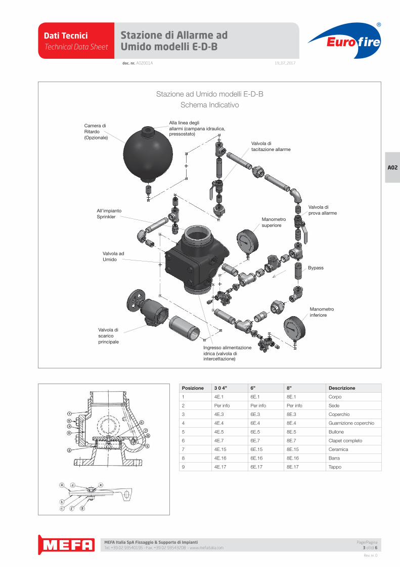
Stazione ad Umido modelli E-D-B
Schema Indicativo
Camera di
Ritardo
(Opzionale)
All’impianto
Sprinkler
Valvola ad
Umido
Valvola di
scarico
principale
Ingresso alimentazione
idrica (valvola di intercettazione)
Valvola di
prova allarme
Valvola di
tacitazione allarme
Alla linea degli
allarmi (campana idraulica, pressostato)
Manometro
superiore
Manometro
inferiore
Bypass
Posizione 3 0 4” 6” 8” Descrizione
1 4E.1 6E.1 8E.1 Corpo
2 Per info Per info Per info Sede
3 4E.3 6E.3 8E.3 Coperchio
4 4E.4 6E.4 8E.4 Guarnizione coperchio
5 4E.5 6E.5 8E.5 Bullone
6 4E.7 6E.7 8E.7 Clapet completo
7 4E.15 6E.15 8E.15 Ceramica
8 4E.16 6E.16 8E.16 Barra
9 4E.17 6E.17 8E.17 Tappo
Dati TecniciTechnical Data Sheet
19_07_2017
Euro fire
MEFA Italia SpA Fissaggio & Supporto di Impianti Tel. +39 02 93540195 - Fax. +39 02 93543208 - www.mefaitalia.com
Rev. nr. 0
A02
Page/Pagina4 of/di 6
doc. nr. A02001A
Stazione di Allarme ad Umido modelli E-D-B
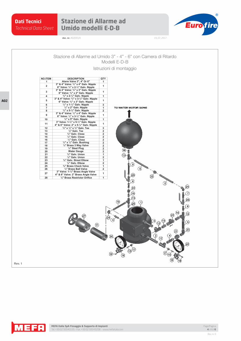
NO.ITEM DESCRIPTION QTY 1 Alarm Valve 3", 4" Or 6" 1
23" & 4" Valve: ¾" x 4" Galv. Nipple
6" Valve: ¾" x 2-½" Galv. Nipple 1
33" & 4" Valve: ¾" x 3" Galv. Nipple
6" Valve: ¾" x 2" Galv. Nipple 1
4 ¾" x 2-½" Galv. Nipple 1
5 3" & 4" Valve: ¾" x 3-½" Galv. Nipple6" Valve: ¾" x 3" Galv. Nipple 1
6 ½" x 1-½" Galv. Nipple 3 7 ½" x 2" Galv. Nipple 1 8 ½" x 5-½" Galv. Nipple 2
9 3" & 4" Valve: ½" x 4" Galv. Nipple6" Valve: ½" x 3-½" Galv. Nipple 1
10 ½" x 5" Galv. Nipple 1
11 3" Valve: 1-½" x 5-½" Galv. Nipple4" & 6" Valve: 2" x 5-½" Galv. Nipple 1
12 ¾" x ½" x ¾" Galv. Tee 313 ½" Galv. Tee 214 ¾" Galv. Close 215 ¼" Galv. Close 216 ½" Galv. Close 217 ½" x ¼" Galv. Bushing 218 ¼" Brass 3 Way Valve 219 ¼" Steel Plug 220 Water Gauge 221 ¾" Galv. Union 122 ½" Galv. Union 223 ¾" Galv. Street Elbow 124 ½" Galv. Elbow 225 ¾" Brass Check Valve 126 ½" Brass Ball Valve 2
273" Valve: 1-½" Brass Angle Valve
4" & 6" Valve: 2" Brass Angle Valve 1
28 ½" Brass Restrictor Orifice 1
Stazione di Allarme ad Umido 3” - 4” - 6” con Camera di Ritardo
Modelli E-D-B
Istruzioni di montaggio
Rev. 1
Dati TecniciTechnical Data Sheet
19_07_2017
Euro fire
MEFA Italia SpA Fissaggio & Supporto di Impianti Tel. +39 02 93540195 - Fax. +39 02 93543208 - www.mefaitalia.com
Rev. nr. 0
A02
Page/Pagina5 of/di 6
doc. nr. A02001A
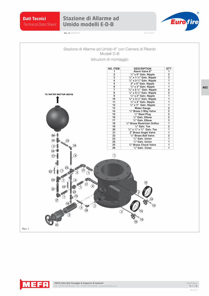
Stazione di Allarme ad Umido modelli E-D-B
NO. ITEM DESCRIPTION QTY 1 Alarm Valve 8" 1 2 ¼" x 6" Galv. Nipple 2 3 ½" x 1-½" Galv. Nipple 3 4 ½" x 2-½" Galv. Nipple 1 5 2" x 5" Galv. Nipple 1 6 ¾" x 3" Galv. Nipple 1 7 ¾" x 2-½" Galv. Nipple 4 8 ½" x 5-½" Galv. Nipple 2 9 ¾" x 2" Galv. Nipple 110 ¾" x 3-½" Galv. Nipple 111 ½" x 2" Galv. Nipple 112 ½" x 3" Galv. Nipple 113 Water Gauge 214 ¼" Brass 3 Way Valve 215 ¼" Steel Plug 216 ½" Galv. Elbow 217 ¾" Galv. Elbow 318 ½" Brass Restrictor Orifice 119 ½" Galv. Tee 220 ¾" x ½" x ¾" Galv. Tee 121 2" Brass Angle Valve 122 ½" Brass Ball Valve 223 ¾" Galv. Union 124 ½" Galv. Union 125 ¾" Brass Check Valve 126 ½" Galv. Close 1
Stazione di Allarme ad Umido 8” con Camera di Ritardo
Modelli D-B
Istruzioni di montaggio
Rev. 1
Dati TecniciTechnical Data Sheet
19_07_2017
Euro fire
MEFA Italia SpA Fissaggio & Supporto di Impianti Tel. +39 02 93540195 - Fax. +39 02 93543208 - www.mefaitalia.com
NOTA GENERALE:
L’attrezzatura presentata in questo bollettino deve essere installata in conformità agli ultimi standard pubblicati dalle Norme UNI EN 12845, National Fire Protection Association, Factory Mutual Research Corporation o altre organizzazioni simili e anche con le disposizioni dei codici governativi o delle ordinanze laddove applicabili.Con la presente pagina tecnica, MEFA Italia intende fornire pertinenti informazioni tecniche, aggiornandole periodicamente.MEFA Italia non si ritiene responsabile in caso di errori di stampa o informazioni inesatte in quanto le stesse possono variare senza preavviso.
The equipment presented in this bulletin is to be installed in accordance with the latest published Standards of the UNI EN 12845, National Fire Protection Association, Factory Mutual Research Corporation, or other similar organizations and also with the provisions of governmental codes or ordinances whenever applicable.With this technical page, MEFA Italia intends to provide relevant technical information, updating them periodically.MEFA Italia is not responsible for any inaccurate print or inaccurate information as these may vary without prior notice.
NOTA EUROFIRE:
Eurofi re è un marchio registrato da MEFA Italia per la presentazione di tutti i prodotti della linea Antincendio.I fornitori dei prodotti Eurofi re vengono rigorosamente selezionati nel rispetto della qualità e delle caratteristiche distintive descrittte in questo documento tecnico.I fornitori dei prodotti potrebbero variare senza preavviso, ma sempre nel rispetto delle caratteristiche qui descritte.
Eurofi re is a registered trademark of MEFA Italia for the presentation of all products of the Fire Protection Line.The suppliers of Eurofi re products are strictly selected in compliance with the quality and distinctive features described in this technical document.Product providers may vary without notice, but always respecting the features described herein.
Rev. nr. 0
A02
Page/Pagina6 of/di 6
doc. nr. A02001A
Stazione di Allarme ad Umido modelli E-D-B
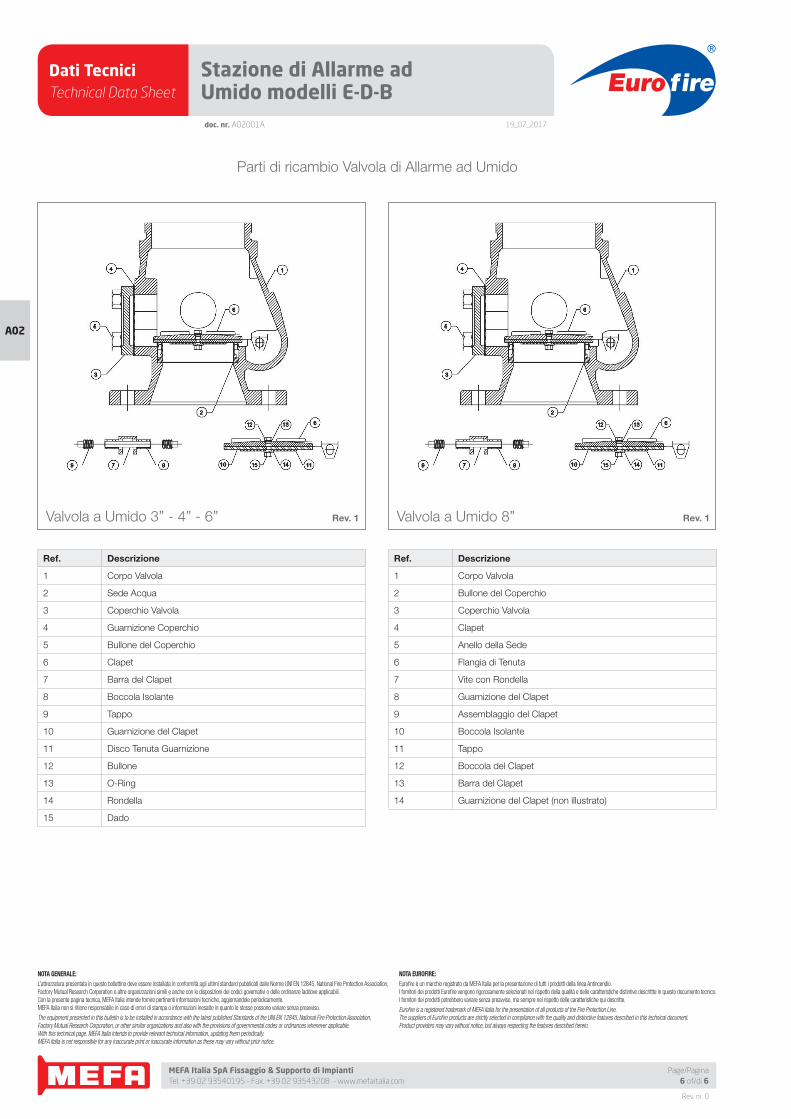
Parti di ricambio Valvola di Allarme ad Umido
Ref. Descrizione
1 Corpo Valvola
2 Sede Acqua
3 Coperchio Valvola
4 Guarnizione Coperchio
5 Bullone del Coperchio
6 Clapet
7 Barra del Clapet
8 Boccola Isolante
9 Tappo
10 Guarnizione del Clapet
11 Disco Tenuta Guarnizione
12 Bullone
13 O-Ring
14 Rondella
15 Dado
Ref. Descrizione
1 Corpo Valvola
2 Bullone del Coperchio
3 Coperchio Valvola
4 Clapet
5 Anello della Sede
6 Flangia di Tenuta
7 Vite con Rondella
8 Guarnizione del Clapet
9 Assemblaggio del Clapet
10 Boccola Isolante
11 Tappo
12 Boccola del Clapet
13 Barra del Clapet
14 Guarnizione del Clapet (non illustrato)
Rev. 1Valvola a Umido 3” - 4” - 6” Rev. 1Valvola a Umido 8”
Dati TecniciTechnical Data Sheet
19_07_2017
Euro fire
MEFA Italia SpA Fissaggio & Supporto di Impianti Tel. +39 02 93540195 - Fax. +39 02 93543208 - www.mefaitalia.com
Rev. nr. 0
A02
A
B
C
D
doc. nr. A02002A
Stazione di Allarme a Secco modelli E-B-A
Diametro nominale
Dimensioni Perdita di caricoin mt/tubo
Peso unitario Codice Valvola
CodiceTrimA B C D s/trim con trim
Poll. DN [mm] [mm] [mm] [mm] [kg/pz] [kg/pz]
4 100 680 387 680 840 3,8 52 62 DPVE40 DPVTRIM40
APPROVED For Listing/Approval Details and Limitations
contact MEFA Sales Representative.
Valvola modello E scanalata/scanalata
Diametro nominale
Dimensioni Perdita di caricoin mt/tubo
Peso unitario Codice Valvola
CodiceTrimA B C D s/trim con trim
Poll. DN [mm] [mm] [mm] [mm] [kg/pz] [kg/pz]
4 100 680 378 680 840 3,8 57 67 DPVB40 DPVTRIM40
6 150 900 495 590 840 10,0 136 146 DPVB60 DPVTRIM60
Valvola modello B fl angiata/scanalata
Diametro nominale
Dimensioni Perdita di caricoin mt/tubo
Peso unitario Codice Valvola
CodiceTrimA B C D s/trim con trim
Poll. DN [mm] [mm] [mm] [mm] [kg/pz] [kg/pz]
3 80 680 375 680 840 1,0 57 67 DPVA30 DPVTRIM30
4 100 680 454 680 840 3,8 60 70 DPVA40 DPVTRIM40
6 150 900 497 590 840 10,0 145 155 DPVA60 DPVTRIM60
Valvola modello A fl angiata/fl angiata
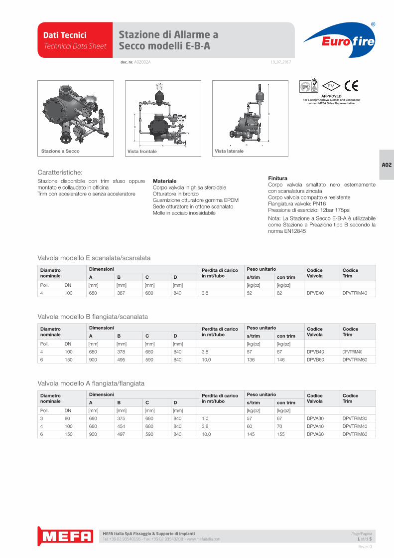
Caratteristiche:
Stazione disponibile con trim sfuso oppure
montato e collaudato in offi cina
Trim con acceleratore o senza acceleratore
Materiale Corpo valvola in ghisa sferoidale
Otturatore in bronzo
Guarnizione otturatore gomma EPDM
Sede otturatore in ottone scanalato
Molle in acciaio inossidabile
Finitura Corpo valvola smaltato nero esternamente
con scanalatura zincata
Corpo valvola compatto e resistente
Flangiatura valvole: PN16
Pressione di esercizio: 12bar 175psi
Nota: La Stazione a Secco E-B-A è utilizzabile
come Stazione a Preazione tipo B secondo la
norma EN12845
Stazione a Secco Vista frontale Vista laterale
Page/Pagina1 of/di 5
Dati TecniciTechnical Data Sheet
19_07_2017
Euro fire
MEFA Italia SpA Fissaggio & Supporto di Impianti Tel. +39 02 93540195 - Fax. +39 02 93543208 - www.mefaitalia.com
Rev. nr. 0
A02
Page/Pagina2 of/di 5
doc. nr. A02002A
Stazione di Allarme a Secco modelli E-B-A
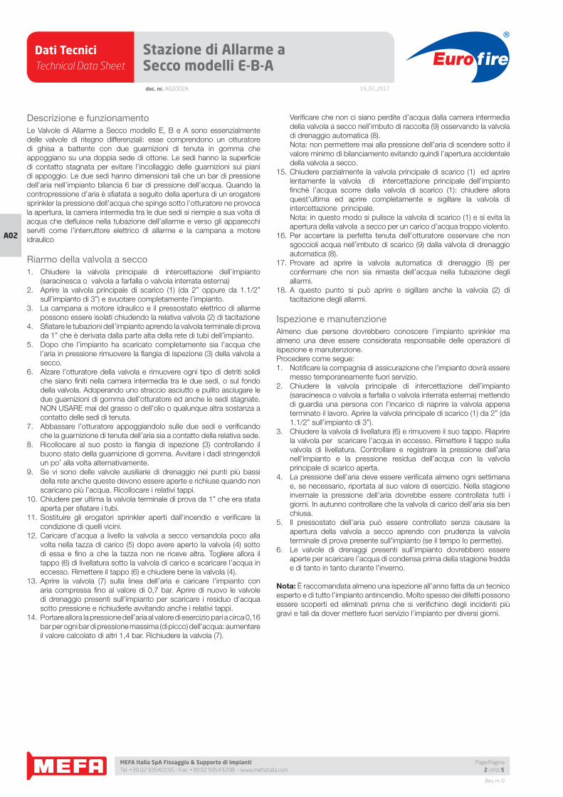
Descrizione e funzionamento
Le Valvole di Allarme a Secco modello E, B e A sono essenzialmente
delle valvole di ritegno differenziali: esse comprendono un otturatore
di ghisa a battente con due guarnizioni di tenuta in gomma che
appoggiano su una doppia sede di ottone. Le sedi hanno la superfi cie
di contatto stagnata per evitare l’incollaggio delle guarnizioni sui piani
di appoggio. Le due sedi hanno dimensioni tali che un bar di pressione
dell’aria nell’impianto bilancia 6 bar di pressione dell’acqua. Quando la
contropressione d’aria è sfi atata a seguito della apertura di un erogatore
sprinkler la pressione dell’acqua che spinge sotto l’otturatore ne provoca
la apertura, la camera intermedia tra le due sedi si riempie a sua volta di
acqua che defl uisce nella tubazione dell’allarme e verso gli apparecchi
serviti come l’interruttore elettrico di allarme e la campana a motore
idraulico
Riarmo della valvola a secco
1. Chiudere la valvola principale di intercettazione dell’impianto
(saracinesca o valvola a farfalla o valvola interrata esterna)
2. Aprire la valvola principale di scarico (1) (da 2” oppure da 1.1/2”
sull’impianto di 3”) e svuotare completamente l’impianto.
3. La campana a motore idraulico e il pressostato elettrico di allarme
possono essere isolati chiudendo la relativa valvola (2) di tacitazione
4. Sfi atare le tubazioni dell’impianto aprendo la valvola terminale di prova
da 1” che è derivata dalla parte alta della rete di tubi dell’impianto.
5. Dopo che l’impianto ha scaricato completamente sia l’acqua che
l’aria in pressione rimuovere la fl angia di ispezione (3) della valvola a
secco.
6. Alzare l’otturatore della valvola e rimuovere ogni tipo di detriti solidi
che siano fi niti nella camera intermedia tra le due sedi, o sul fondo
della valvola. Adoperando uno straccio asciutto e pulito asciugare le
due guarnizioni di gomma dell’otturatore ed anche le sedi stagnate.
NON USARE mai del grasso o dell’olio o qualunque altra sostanza a
contatto delle sedi di tenuta.
7. Abbassare l’otturatore appoggiandolo sulle due sedi e verifi cando
che la guarnizione di tenuta dell’aria sia a contatto della relativa sede.
8. Ricollocare al suo posto la fl angia di ispezione (3) controllando il
buono stato della guarnizione di gomma. Avvitare i dadi stringendoli
un po’ alla volta alternativamente.
9. Se vi sono delle valvole ausiliarie di drenaggio nei punti più bassi
della rete anche queste devono essere aperte e richiuse quando non
scaricano più l’acqua. Ricollocare i relativi tappi.
10. Chiudere per ultima la valvola terminale di prova da 1” che era stata
aperta per sfi atare i tubi.
11. Sostituire gli erogatori sprinkler aperti dall’incendio e verifi care la
condizione di quelli vicini.
12. Caricare d’acqua a livello la valvola a secco versandola poco alla
volta nella tazza di carico (5) dopo avere aperto la valvola (4) sotto
di essa e fi no a che la tazza non ne riceve altra. Togliere allora il
tappo (6) di livellatura sotto la valvola di carico e scaricare l’acqua in
eccesso. Rimettere il tappo (6) e chiudere bene la valvola (4).
13. Aprire la valvola (7) sulla linea dell’aria e caricare l’impianto con
aria compressa fi no al valore di 0,7 bar. Aprire di nuovo le valvole
di drenaggio presenti sull’impianto per scaricare i residuo d’acqua
sotto pressione e richiuderle avvitando anche i relativi tappi.
14. Portare allora la pressione dell’aria al valore di esercizio pari a circa 0,16
bar per ogni bar di pressione massima (di picco) dell’acqua: aumentare
il valore calcolato di altri 1,4 bar. Richiudere la valvola (7).
Verifi care che non ci siano perdite d’acqua dalla camera intermedia
della valvola a secco nell’imbuto di raccolta (9) osservando la valvola
di drenaggio automatica (8).
Nota: non permettere mai alla pressione dell’aria di scendere sotto il
valore minimo di bilanciamento evitando quindi l’apertura accidentale
della valvola a secco.
15. Chiudere parzialmente la valvola principale di scarico (1) ed aprire
lentamente la valvola di intercettazione principale dell’impianto
fi nchè l’acqua scorre dalla valvola di scarico (1): chiudere allora
quest’ultima ed aprire completamente e sigillare la valvola di
intercettazione principale.
Nota: in questo modo si pulisce la valvola di scarico (1) e si evita la
apertura della valvola a secco per un carico d’acqua troppo violento.
16. Per accertare la perfetta tenuta dell’otturatore osservare che non
sgoccioli acqua nell’imbuto di scarico (9) dalla valvola di drenaggio
automatica (8).
17. Provare ad aprire la valvola automatica di drenaggio (8) per
confermare che non sia rimasta dell’acqua nella tubazione degli
allarmi.
18. A questo punto si può aprire e sigillare anche la valvola (2) di
tacitazione degli allarmi.
Ispezione e manutenzione
Almeno due persone dovrebbero conoscere l’impianto sprinkler ma
almeno una deve essere considerata responsabile delle operazioni di
ispezione e manutenzione.
Procedere come segue:
1. Notifi care la compagnia di assicurazione che l’impianto dovrà essere
messo temporaneamente fuori servizio.
2. Chiudere la valvola principale di intercettazione dell’impianto
(saracinesca o valvola a farfalla o valvola interrata esterna) mettendo
di guardia una persona con l’incarico di riaprire la valvola appena
terminato il lavoro. Aprire la valvola principale di scarico (1) da 2” (da
1.1/2” sull’impianto di 3”).
3. Chiudere la valvola di livellatura (6) e rimuovere il suo tappo. Riaprire
la valvola per scaricare l’acqua in eccesso. Rimettere il tappo sulla
valvola di livellatura. Controllare e registrare la pressione dell’aria
nell’impianto e la pressione residua dell’acqua con la valvola
principale di scarico aperta.
4. La pressione dell’aria deve essere verifi cata almeno ogni settimana
e, se necessario, riportata al suo valore di esercizio. Nella stagione
invernale la pressione dell’aria dovrebbe essere controllata tutti i
giorni. In autunno controllare che la valvola di carico dell’aria sia ben
chiusa.
5. Il pressostato dell’aria può essere controllato senza causare la
apertura della valvola a secco aprendo con prudenza la valvola
terminale di prova presente sull’impianto (se il tempo lo permette).
6. Le valvole di drenaggi presenti sull’impianto dovrebbero essere
aperte per scaricare l’acqua di condensa prima della stagione fredda
e di tanto in tanto durante l’inverno.
Nota: È raccomandata almeno una ispezione all’anno fatta da un tecnico
esperto e di tutto l’impianto antincendio. Molto spesso dei difetti possono
essere scoperti ed eliminati prima che si verifi chino degli incidenti più
gravi e tali da dover mettere fuori servizio l’impianto per diversi giorni.
Dati TecniciTechnical Data Sheet
19_07_2017
Euro fire
MEFA Italia SpA Fissaggio & Supporto di Impianti Tel. +39 02 93540195 - Fax. +39 02 93543208 - www.mefaitalia.com
Rev. nr. 0
A02
Stazione di Allarme a Secco modelli E-B-Adoc. nr. A02002A
Page/Pagina3 of/di 5
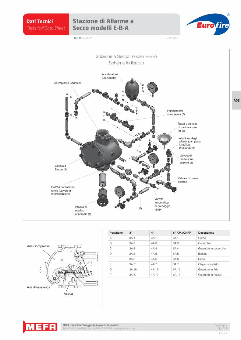
Stazione a Secco modelli E-B-A
Schema Indicativo
All’impianto Sprinkler
Acceleratore
(Opzionale)
Valvola a
Secco (3)
Dall’Alimentazione
idrica (valvole di intercettazione)
Valvola di
scarico
principale (1)
Valvola
automatica
di drenaggio
(8) (9)(6)
Valvola di
tacitazione
allarme (2)
Tazza e valvola
di carico acqua
(4) (5)
Ingresso aria
compressa (7)
Valvola di prova
allarme
Alla linea degli allarmi (campana idraulica, pressostato)
Aria Compressa
Aria Atmosferica
Acqua
Posizione 3” 4” 6” F.M./CNPP Descrizione
A 3A.1 4A.1 6A.1 Corpo
B 3A.3 4A.3 6A.3 Coperchio
C 3A.4 4A.4 6A.4 Guarnizione coperchio
D 3A.5 4A.5 6A.5 Bullone
E 3A.6 4A.6 6A.6 Dado
K 3A.7 4A.7 6A.7 Clapet completo
O 3A.16 4A.16 6A.16 Guarnizione Aria
P 3A.17 4A.17 6A.17 Guarnizione Acqua
Dati TecniciTechnical Data Sheet
19_07_2017
Euro fire
MEFA Italia SpA Fissaggio & Supporto di Impianti Tel. +39 02 93540195 - Fax. +39 02 93543208 - www.mefaitalia.com
Rev. nr. 0
A02
doc. nr. A02002A
Stazione di Allarme a Secco modelli E-B-A
Page/Pagina4 of/di 5
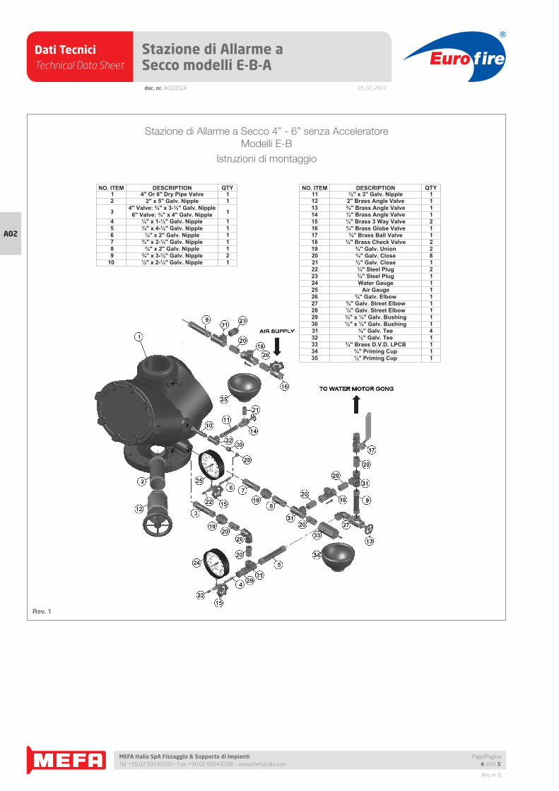
Stazione di Allarme a Secco 4” - 6” senza Acceleratore
Modelli E-B
Istruzioni di montaggio
Rev. 1
NO. ITEM DESCRIPTION QTY11 ½" x 3" Galv. Nipple 112 2" Brass Angle Valve 113 ¾" Brass Angle Valve 114 ½" Brass Angle Valve 115 ¼" Brass 3 Way Valve 216 ¾" Brass Globe Valve 117 ¾" Brass Ball Valve 118 ¾" Brass Check Valve 219 ¾" Galv. Union 220 ¾" Galv. Close 821 ½" Galv. Close 122 ¼" Steel Plug 223 ¾" Steel Plug 124 Water Gauge 125 Air Gauge 126 ¾" Galv. Elbow 127 ¾" Galv. Street Elbow 128 ¼" Galv. Street Elbow 129 ¾" x ¼" Galv. Bushing 130 ½" x ¼" Galv. Bushing 131 ¾" Galv. Tee 432 ½" Galv. Tee 133 ¾" Brass D.V.D. LPCB 134 ¾" Priming Cup 135 ½" Priming Cup 1
NO. ITEM DESCRIPTION QTY 1 4" Or 6" Dry Pipe Valve 1 2 2" x 5" Galv. Nipple 1
3 4" Valve: ¾" x 3-½" Galv. Nipple6" Valve: ¾" x 4" Galv. Nipple 1
4 ¼" x 1-½" Galv. Nipple 1 5 ¾" x 4-½" Galv. Nipple 1 6 ¼" x 2" Galv. Nipple 1 7 ¾" x 2-½" Galv. Nipple 1 8 ¾" x 2" Galv. Nipple 1 9 ¾" x 3-½" Galv. Nipple 210 ½" x 2-½" Galv. Nipple 1
Dati TecniciTechnical Data Sheet
19_07_2017
Euro fire
MEFA Italia SpA Fissaggio & Supporto di Impianti Tel. +39 02 93540195 - Fax. +39 02 93543208 - www.mefaitalia.com
NOTA GENERALE:
L’attrezzatura presentata in questo bollettino deve essere installata in conformità agli ultimi standard pubblicati dalle Norme UNI EN 12845, National Fire Protection Association, Factory Mutual Research Corporation o altre organizzazioni simili e anche con le disposizioni dei codici governativi o delle ordinanze laddove applicabili.Con la presente pagina tecnica, MEFA Italia intende fornire pertinenti informazioni tecniche, aggiornandole periodicamente.MEFA Italia non si ritiene responsabile in caso di errori di stampa o informazioni inesatte in quanto le stesse possono variare senza preavviso.
The equipment presented in this bulletin is to be installed in accordance with the latest published Standards of the UNI EN 12845, National Fire Protection Association, Factory Mutual Research Corporation, or other similar organizations and also with the provisions of governmental codes or ordinances whenever applicable.With this technical page, MEFA Italia intends to provide relevant technical information, updating them periodically.MEFA Italia is not responsible for any inaccurate print or inaccurate information as these may vary without prior notice.
NOTA EUROFIRE:
Eurofi re è un marchio registrato da MEFA Italia per la presentazione di tutti i prodotti della linea Antincendio.I fornitori dei prodotti Eurofi re vengono rigorosamente selezionati nel rispetto della qualità e delle caratteristiche distintive descrittte in questo documento tecnico.I fornitori dei prodotti potrebbero variare senza preavviso, ma sempre nel rispetto delle caratteristiche qui descritte.
Eurofi re is a registered trademark of MEFA Italia for the presentation of all products of the Fire Protection Line.The suppliers of Eurofi re products are strictly selected in compliance with the quality and distinctive features described in this technical document.Product providers may vary without notice, but always respecting the features described herein.
Rev. nr. 0
A02
doc. nr. A02002A
Stazione di Allarme a Secco modelli E-B-A
Page/Pagina5 of/di 5
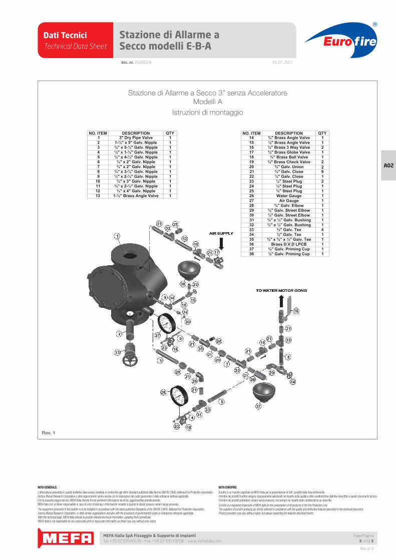
Stazione di Allarme a Secco 3” senza Acceleratore
Modelli A
Istruzioni di montaggio
Rev. 1
NO. ITEM DESCRIPTION QTY14 ¾" Brass Angle Valve 115 ½" Brass Angle Valve 116 ¼" Brass 3 Way Valve 217 ¾" Brass Globe Valve 118 ¾" Brass Ball Valve 119 ¾" Brass Check Valve 220 ¾" Galv. Union 221 ¾" Galv. Close 922 ½" Galv. Close 123 ¼" Steel Plug 224 ½" Steel Plug 125 ¾" Steel Plug 126 Water Gauge 127 Air Gauge 128 ¾" Galv. Elbow 129 ¾" Galv. Street Elbow 130 ¼" Galv. Street Elbow 131 ¾" x ¼" Galv. Bushing 132 ½" x ¼" Galv. Bushing 133 ¾" Galv. Tee 434 ½" Galv. Tee 135 ¾" x ¾" x ½" Galv. Tee 136 Brass D.V.D LPCB 137 ¾" Galv. Priming Cup 138 ½" Galv. Priming Cup 1
NO. ITEM DESCRIPTION QTY 1 3" Dry Pipe Valve 1 2 1-½" x 5" Galv. Nipple 1 3 ¾" x 5-½" Galv. Nipple 1 4 ¼" x 1-½" Galv. Nipple 1 5 ¾" x 4-½" Galv. Nipple 1 6 ¼" x 2" Galv. Nipple 1 7 ¾" x 2" Galv. Nipple 1 8 ¾" x 3-½" Galv. Nipple 1 9 ½" x 2-½" Galv. Nipple 110 ½" x 3" Galv. Nipple 111 ¾" x 2-½" Galv. Nipple 112 ¾" x 4" Galv. Nipple 113 1-½" Brass Angle Valve 1
Dati TecniciTechnical Data Sheet
19_07_2017
Euro fire
MEFA Italia SpA Fissaggio & Supporto di Impianti Tel. +39 02 93540195 - Fax. +39 02 93543208 - www.mefaitalia.com
Rev. nr. 0
A02
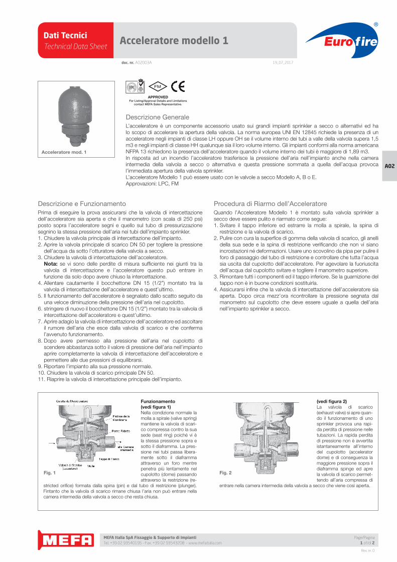
Funzionamento (vedi fi gura 1)Nella condizione normale la
molla a spirale (valve spring)
mantiene la valvola di scari-
co compressa contro la sua
sede (seat ring) poiché vi è
la stessa pressione sopra e
sotto il diaframma. La pres-
sione nei tubi passa libera-
mente sotto il diaframma
attraverso un foro mentre
penetra più lentamente nel
cupolotto (dome) passando
attraverso la restrizione (re-
stricted orifi ce) formata dalla spina (pin) e dal tubo di restrizione (plunger).
Fintanto che la valvola di scarico rimane chiusa l’aria non può entrare nella
camera intermedia della valvola a secco che resta chiusa.
(vedi fi gura 2)La valvola di scarico
(exhaust valve) si apre quan-
do il funzionamento di uno
sprinkler provoca una rapi-
da perdita di pressione nelle
tubazioni. La rapida perdita
di pressione non è avvertita
istantaneamente all’interno
del cupolotto (accelerator
dome) e di conseguenza la
maggiore pressione sopra il
diaframma spinge ed apre
la valvola di scarico permet-
tendo all’aria compressa di
entrare nella camera intermedia della valvola a secco che viene così aperta.
doc. nr. A02003A
Acceleratore modello 1
APPROVED For Listing/Approval Details and Limitations
contact MEFA Sales Representative.
Acceleratore mod. 1
Page/Pagina1 of/di 2
Descrizione Generale
L’acceleratore è un componente accessorio usato sui grandi impianti sprinkler a secco o alternativi ed ha
lo scopo di accelerare la apertura della valvola. La norma europea UNI EN 12845 richiede la presenza di un
acceleratore negli impianti di classe LH oppure OH se il volume interno dei tubi a valle della valvola supera 1,5
m3 e negli impianti di classe HH qualunque sia il loro volume interno. Gli impianti conformi alla norma americana
NFPA 13 richiedono la presenza dell’acceleratore quando il volume interno dei tubi è maggiore di 1,89 m3.
In risposta ad un incendio l’acceleratore trasferisce la pressione dell’aria nell’impianto anche nella camera
intermedia della valvola a secco o alternativa e questa pressione sommata a quella dell’acqua provoca
l’immediata apertura della valvola sprinkler.
L’acceleratore Modello 1 può essere usato con le valvole a secco Modello A, B o E.
Approvazioni: LPC, FM
Descrizione e Funzionamento
Prima di eseguire la prova assicurarsi che la valvola di intercettazione
dell’acceleratore sia aperta e che il manometro (con scala di 250 psi)
posto sopra l’acceleratore segni e quello sul tubo di pressurizzazione
segnino la stessa pressione dell’aria nei tubi dell’impianto sprinkler.
1. Chiudere la valvola principale di intercettazione dell’impianto.
2. Aprire la valvola principale di scarico DN 50 per togliere la pressione
dell’acqua da sotto l’otturatore della valvola a secco.
3. Chiudere la valvola di intercettazione dell’acceleratore.
Nota: se vi sono delle perdite di misura suffi ciente nei giunti tra la
valvola di intercettazione e l’acceleratore questo può entrare in
funzione da solo dopo avere chiuso la intercettazione.
4. Allentare cautamente il bocchettone DN 15 (1/2”) montato tra la
valvola di intercettazione dell’acceleratore e quest’ultimo.
5. Il funzionamento dell’acceleratore è segnalato dallo scatto seguito da
una veloce diminuzione della pressione dell’aria nel cupolotto.
6. stringere di nuovo il bocchettone DN 15 (1/2”) montato tra la valvola di
intercettazione dell’acceleratore e quest’ultimo.
7. Aprire adagio la valvola di intercettazione dell’acceleratore ed ascoltare
il rumore dell’aria che esce dalla valvola di scarico e che conferma
l’avvenuto funzionamento.
8. Dopo avere permesso alla pressione dell’aria nel cupolotto di
scendere abbastanza sotto il valore di pressione dell’aria nell’impianto
aprire completamente la valvola di intercettazione dell’acceleratore e
permettere alle due pressioni di equilibrarsi.
9. Riportare l’impianto alla sua pressione normale.
10. Chiudere la valvola di scarico principale DN 50.
11. Riaprire la valvola di intercettazione principale dell’impianto.
Procedura di Riarmo dell’Acceleratore
Quando l’Acceleratore Modello 1 è montato sulla valvola sprinkler a
secco deve essere pulito e riarmato come segue:
1. Svitare il tappo inferiore ed estrarre la molla a spirale, la spina di
restrizione e la valvola di scarico.
2. Pulire con cura la superfi ce di gomma della valvola di scarico, gli anelli
della sua sede e la spina di restrizione verifi cando che non vi siano
incrostazioni né deformazioni. Usare uno scovolino da pipa per pulire il
foro di passaggio del tubo di restrizione e controllare che tutta l’acqua
sia uscita dal cupolotto dell’acceleratore. Per agevolare la fuoriuscita
dell’acqua dal cupolotto svitare e togliere il manometro superiore.
3. Rimontare tutti i componenti ed il tappo inferiore. Se la guarnizione del
tappo non è in buone condizioni sostituirla.
4. Assicurarsi infi ne che la valvola di intercettazione dell’acceleratore sia
aperta. Dopo circa mezz’ora ricontrollare la pressione segnata dal
manometro sul cupolotto che deve essere uguale a quella dell’aria
nell’impianto sprinkler a secco.
Fig. 1 Fig. 2
Dati TecniciTechnical Data Sheet
19_07_2017
Euro fire
MEFA Italia SpA Fissaggio & Supporto di Impianti Tel. +39 02 93540195 - Fax. +39 02 93543208 - www.mefaitalia.com
Rev. nr. 0
A02
Page/Pagina2 of/di 2
doc. nr. A02003A
Acceleratore modello 1
Rev. 1
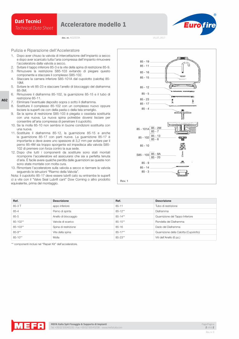
Pulizia e Riparazione dell’Acceleratore
1. Dopo aver chiuso la valvola di intercettazione dell’impianto a secco
e dopo aver scaricato tutta l’aria compressa dell’impianto rimuovere
l’acceleratore dalla valvola a secco.
2. Svitare il tappo inferiore 85-3 e la vite della spina di restrizione 85-9.
3. Rimuovere la restrizione S85-103 evitando di piegare questo
componente e staccare il complesso S85-102.
4. Staccare la camera inferiore S85-101A dal cupolotto (calotta) 85-
19M.
5. Svitare le viti 85-23 e staccare l’anello di bloccaggio del diaframma
85-5M.
6. Rimuovere il diaframma 85-102, la guarnizione 85-15 e il tubo di
restrizione 85-11.
7. Eliminare l’eventuale deposito sopra o sotto il diaframma.
8. Sostituire il complesso 85-102 con un complesso nuovo oppure
lisciare la superfi cie con della pasta o della tela smeriglio.
9. Se la spina di restrizione S85-103 è piegata o ossidata sostituirla
con una nuova. La nuova spina potrebbe doversi lisciare per
consentire all’aria compressa di penetrare il cupolotto.
10. Se la molla 85-10 non sembra in buone condizioni sostituirla con
una nuova.
11. Sostituire il diaframma 85-12, la guarnizione 85-15 e anche
la guarnizione 85-17 con parti nuove. La guarnizione 85-17 è
importante e deve avere uno spessore di 3,2 mm per evitare per il
perno 85-4M sia troppo sporgente ed impedisca alla valvola S85-
102 di premere con forza contro la sua sede.
12. Dopo che tutti i componenti da sostituire sono stati montati
ricomporre l’acceleratore ed assicurarsi che sia a perfetta tenuta
d’aria. È facile avere qualche perdita dalle guarnizioni se queste non
sono state montate con molta cura.
13. Rimontare l’acceleratore sulla valvola a secco e riarmare la valvola
seguendo le istruzioni “Riarmo della Valvola”.
Nota: il cupolotto 85-17 deve essere lubrifi cato su entrambe le superfi
ci a vite con il “Valve Seal Lubrifi cant” Dow Corning o altro prodotto
equivalente, prima del montaggio.
85 - 19
85 - 11
85 - 16
85 - 15
85 - 12
85 - 5
85 - 23
85 - 17
85 - 4
85 - 101A
85 - 102
85 - 10
S85 - 103
85 - 9
85 - 1485 - 3
85 - 2M85 - 7
85 - 1385 - 6
85 - 8A85 - 20
Ref. Descrizione Ref. Descrizione
85-3 T appo inferiore 85-11 Tubo di restrizione
85-4 Perno di spinta 85-12** Diaframma
85-5 Anello di bloccaggio 85-14** Guarnizione del Tappo Inferiore
85-102** Valvola di scarico 85-15** Rondella del Diaframma
85-103** Spina di restrizione 85-16 Dado del Diaframma
85-9** Vite della spina 85-17** Guarnizione della Calotta (Cupolotto)
85-10** Molla 85-23** Viti dell’Anello (6 pz.)
** componenti inclusi nel “Repair Kit” dell’acceleratore.
Dati TecniciTechnical Data Sheet
19_07_2017
Euro fire
MEFA Italia SpA Fissaggio & Supporto di Impianti Tel. +39 02 93540195 - Fax. +39 02 93543208 - www.mefaitalia.com
Rev. nr. 0
A02
doc. nr. A02004A
Dispositivo Mantenimento Aria modello G
Page/Pagina1 of/di 2
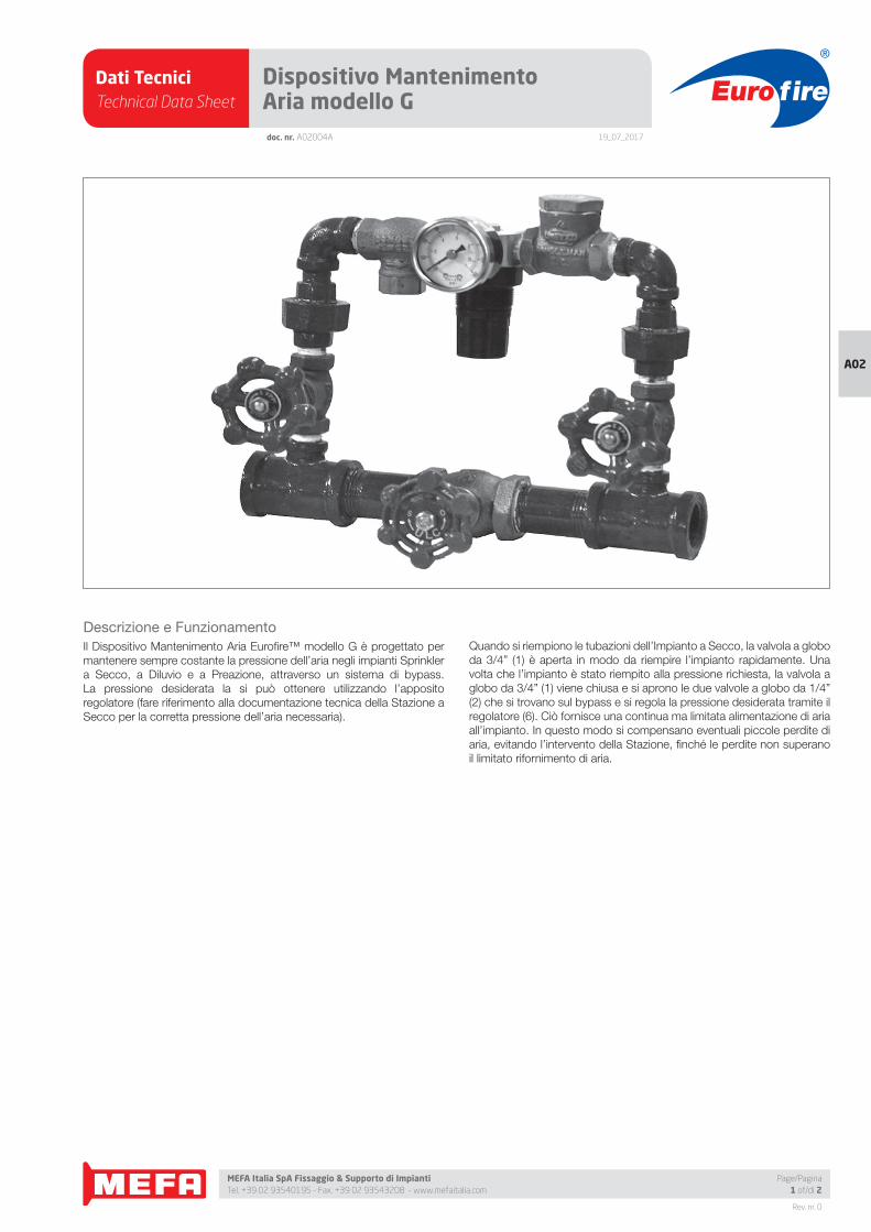
Descrizione e Funzionamento
Il Dispositivo Mantenimento Aria Eurofi re™ modello G è progettato per
mantenere sempre costante la pressione dell’aria negli impianti Sprinkler
a Secco, a Diluvio e a Preazione, attraverso un sistema di bypass.
La pressione desiderata la si può ottenere utilizzando l’apposito
regolatore (fare riferimento alla documentazione tecnica della Stazione a
Secco per la corretta pressione dell’aria necessaria).
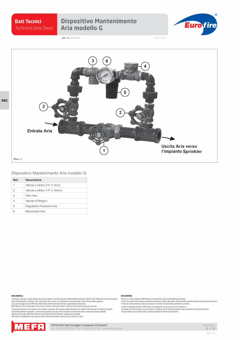
Quando si riempiono le tubazioni dell’Impianto a Secco, la valvola a globo
da 3/4” (1) è aperta in modo da riempire l’impianto rapidamente. Una
volta che l’impianto è stato riempito alla pressione richiesta, la valvola a
globo da 3/4” (1) viene chiusa e si aprono le due valvole a globo da 1/4”
(2) che si trovano sul bypass e si regola la pressione desiderata tramite il
regolatore (6). Ciò fornisce una continua ma limitata alimentazione di aria
all’impianto. In questo modo si compensano eventuali piccole perdite di
aria, evitando l’intervento della Stazione, fi nché le perdite non superano
il limitato rifornimento di aria.
Dati TecniciTechnical Data Sheet
19_07_2017
Euro fire
MEFA Italia SpA Fissaggio & Supporto di Impianti Tel. +39 02 93540195 - Fax. +39 02 93543208 - www.mefaitalia.com
Rev. nr. 0
A02
Page/Pagina2 of/di 2
doc. nr. A02004A
Dispositivo Mantenimento Aria modello G
Ref. Descrizione
1 Valvola a Globo 3/4” (1.9cm)
2 Valvola a Globo 1/4” (1.64cm)
3 Filtro Aria
4 Valvola di Ritegno
5 Regolatore Pressione Aria
6 Manometro Aria
Dispositivo Mantenimento Aria modello G
Rev. 1
NOTA GENERALE:
L’attrezzatura presentata in questo bollettino deve essere installata in conformità agli ultimi standard pubblicati dalle Norme UNI EN 12845, National Fire Protection Association, Factory Mutual Research Corporation o altre organizzazioni simili e anche con le disposizioni dei codici governativi o delle ordinanze laddove applicabili.Con la presente pagina tecnica, MEFA Italia intende fornire pertinenti informazioni tecniche, aggiornandole periodicamente.MEFA Italia non si ritiene responsabile in caso di errori di stampa o informazioni inesatte in quanto le stesse possono variare senza preavviso.
The equipment presented in this bulletin is to be installed in accordance with the latest published Standards of the UNI EN 12845, National Fire Protection Association, Factory Mutual Research Corporation, or other similar organizations and also with the provisions of governmental codes or ordinances whenever applicable.With this technical page, MEFA Italia intends to provide relevant technical information, updating them periodically.MEFA Italia is not responsible for any inaccurate print or inaccurate information as these may vary without prior notice.
NOTA EUROFIRE:
Eurofi re è un marchio registrato da MEFA Italia per la presentazione di tutti i prodotti della linea Antincendio.I fornitori dei prodotti Eurofi re vengono rigorosamente selezionati nel rispetto della qualità e delle caratteristiche distintive descrittte in questo documento tecnico.I fornitori dei prodotti potrebbero variare senza preavviso, ma sempre nel rispetto delle caratteristiche qui descritte.
Eurofi re is a registered trademark of MEFA Italia for the presentation of all products of the Fire Protection Line.The suppliers of Eurofi re products are strictly selected in compliance with the quality and distinctive features described in this technical document.Product providers may vary without notice, but always respecting the features described herein.
Dati TecniciTechnical Data Sheet
19_07_2017
Euro fire
MEFA Italia SpA Fissaggio & Supporto di Impianti Tel. +39 02 93540195 - Fax. +39 02 93543208 - www.mefaitalia.com
Rev. nr. 0
A02A02
Page/Pagina1 of/di 4
doc. nr. A02005A
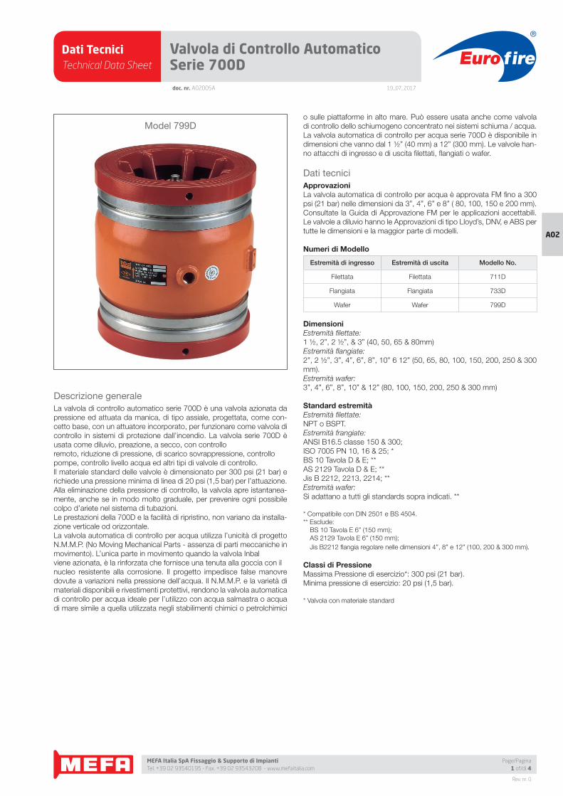
Valvola di Controllo Automatico Serie 700D
Descrizione generale
La valvola di controllo automatico serie 700D è una valvola azionata da
pressione ed attuata da manica, di tipo assiale, progettata, come con-
cetto base, con un attuatore incorporato, per funzionare come valvola di
controllo in sistemi di protezione dall’incendio. La valvola serie 700D è
usata come diluvio, preazione, a secco, con controllo
remoto, riduzione di pressione, di scarico sovrappressione, controllo
pompe, controllo livello acqua ed altri tipi di valvole di controllo.
Il materiale standard delle valvole è dimensionato per 300 psi (21 bar) e
richiede una pressione minima di linea di 20 psi (1,5 bar) per l’attuazione.
Alla eliminazione della pressione di controllo, la valvola apre istantanea-
mente, anche se in modo molto graduale, per prevenire ogni possibile
colpo d’ariete nel sistema di tubazioni.
Le prestazioni della 700D e la facilità di ripristino, non variano da installa-
zione verticale od orizzontale.
La valvola automatica di controllo per acqua utilizza l’unicità di progetto
N.M.M.P. (No Moving Mechanical Parts - assenza di parti meccaniche in
movimento). L’unica parte in movimento quando la valvola Inbal
viene azionata, è la rinforzata che fornisce una tenuta alla goccia con il
nucleo resistente alla corrosione. Il progetto impedisce false manovre
dovute a variazioni nella pressione dell’acqua. Il N.M.M.P. e la varietà di
materiali disponibili e rivestimenti protettivi, rendono la valvola automatica
di controllo per acqua ideale per l’utilizzo con acqua salmastra o acqua
di mare simile a quella utilizzata negli stabilimenti chimici o petrolchimici
o sulle piattaforme in alto mare. Può essere usata anche come valvola
di controllo dello schiumogeno concentrato nei sistemi schiuma / acqua.
La valvola automatica di controllo per acqua serie 700D è disponibile in
dimensioni che vanno dal 1 ½” (40 mm) a 12” (300 mm). Le valvole han-
no attacchi di ingresso e di uscita fi lettati, fl angiati o wafer.
Dati tecnici
ApprovazioniLa valvola automatica di controllo per acqua è approvata FM fi no a 300
psi (21 bar) nelle dimensioni da 3”, 4”, 6” e 8” ( 80, 100, 150 e 200 mm).
Consultate la Guida di Approvazione FM per le applicazioni accettabili.
Le valvole a diluvio hanno le Approvazioni di tipo Lloyd’s, DNV, e ABS per
tutte le dimensioni e la maggior parte di modelli.
Numeri di Modello
Estremità di ingresso Estremità di uscita Modello No.
Filettata Filettata 711D
Flangiata Flangiata 733D
Wafer Wafer 799D
DimensioniEstremità fi lettate:
1 ½, 2”, 2 ½”, & 3” (40, 50, 65 & 80mm)
Estremità fl angiate:
2”, 2 ½”, 3”, 4”, 6”, 8”, 10” 6 12” (50, 65, 80, 100, 150, 200, 250 & 300
mm).
Estremità wafer:
3”, 4”, 6”, 8”, 10” & 12” (80, 100, 150, 200, 250 & 300 mm)
Standard estremitàEstremità fi lettate:
NPT o BSPT.
Estremità frangiate:
ANSI B16.5 classe 150 & 300;
ISO 7005 PN 10, 16 & 25; *
BS 10 Tavola D & E; **
AS 2129 Tavola D & E; **
Jis B 2212, 2213, 2214; **
Estremità wafer:
Si adattano a tutti gli standards sopra indicati. **
* Compatibile con DIN 2501 e BS 4504.
** Esclude:
BS 10 Tavola E 6” (150 mm);
AS 2129 Tavola E 6” (150 mm);
Jis B2212 fl angia regolare nelle dimensioni 4”, 8” e 12” (100, 200 & 300 mm).
Classi di PressioneMassima Pressione di esercizio*: 300 psi (21 bar).
Minima pressione di esercizio: 20 psi (1,5 bar).
* Valvola con materiale standard
Model 799D
Dati TecniciTechnical Data Sheet
19_07_2017
Euro fire
MEFA Italia SpA Fissaggio & Supporto di Impianti Tel. +39 02 93540195 - Fax. +39 02 93543208 - www.mefaitalia.com
Rev. nr. 0
A02A02
doc. nr. A02005A
Valvola di Controllo Automatico Serie 700D
Page/Pagina2 of/di 4
Campo di temperaturaAcqua: massimo + 150 °F (+ 65°C)
Posizione di installazioneStandardVerticale o orizzontale
MaterialiStandardCorpo valvola:
Acciaio al carbonio (SAE 1021).
Estremità valvola:
Ghisa malleabile (ASTM A536 65-45-12).
Manica:
SMR5 Elastomero rinforzato con
Poliestere e Kevlar.
OpzionaliAcciaio Fuso;
Bronzo;
Nickel Alluminio Bronzo;
Acciaio inossidabile AISI 316;
Acciaio inossidabile Super Austenitico;
Acciaio inossidabile Super Duplex;
Titanio.
RivestimentiStandardRivestimento in polvere epossidica.
Spessore: 0.004” (0.1 mm) superfi ci esterne ed
interne
OpzionaliRivestimento ad alto spessore epossidico e
fi nitura poliuretanica. Spessore: 0.01” (0.3 mm).
Rivestimento in Halar®. Spessore: 0.02” (0.5
mm).
Halar® è un marchi registrato di Ausimont USA Inc.
Caratteristiche• La valvola Inbal, progettata per essere una
valvola di controllo, come concetto base uti-
lizza un attuatore a manica incorporato.
• La costruzione con assenza di parti meccan-
iche in movimento (N.M.M.P.), assicura una
lunga vita di servizio affi dabile, riducendo i
costi di manutenzione.
• La costruzione N.M.M.P. assicura operazio-
ni senza attrito. Assenza di bloccaggi dopo
la permanenza per prolungati periodi in po-
sizione chiusa. Adatta per acqua salmastra
e acqua di mare.
• Veloce ma graduale caratteristica di apertura
che elimina i colpi di ariete e danni conseg-
uenti.
• La pressione di linea o una pressione equiva-
lente indipendente di comando, è suffi ciente
a chiudere la valvola ermeticamente.
• Prestazioni di chiusura delicate dovute alle
caratteristiche costruttive della valvola Inbal. Non utilizza molle per assicurare una chiusu-
ra senza picchi di pressione.
• Pressione nominale di 300 psi (21 bar) per
materiali standard dovuti alla costruzione ro-
busta.
• Adatta per installazione verticale o orizzon-
tale senza ripercussioni sul funzionamento
della valvola Inbal.• Costruzione leggera di facile installazione e
manutenzione.
• Disponibile con estremità fi lettate, fl angiate e
wafer, in accordo a vari standards.
• Principio unico di operatività che previene in-
terventi intempestivi per picchi di pressione
idraulica.
• Ampio campo di dimensioni per un’ideale
progettazione di sistemi.
• Costruzione compatta minimo spazio richie-
sto per la valvola ed il trim. Permette l’instal-
lazione in spazi ristretti.
• Rivestimenti con vernici epossidiche forniti
nella esecuzione standard assicurano una
eccellente resistenza alla corrosione.
• Ampia varietà di materiali disponibili per as-
sicurare un servizio senza corrosione anche
con severe condizioni ambientali.
• Compatibile con commando elettrico, pneu-
matico e/o idraulico.
• Eccellente prestazione di regolazione in un
ampio campo di portate e pressioni di linea.
• Ampia selezione di valvole pilota, attuatori e
accessori per defi nire la valvola di controllo
più adatta allo scopo.
• Una singola valvola automatica può essere
utilizzata per più funzioni di controllo.
• Ogni singola valvola è provata idraulicamente
nelle condizioni reali di portata e pressione.
• Progetto innovativo con una lunga storia di
provata affi dabilità.
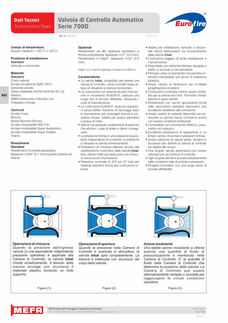
Operazione di aperturaQuando la pressione nella Camera di Controllo è scaricata in atmosfera, la valvola Inbal apre completamente. La manica è trattenuta con sicurezza dal corpo della valvola.
Operazione di chiusuraQuando la pressione dall'ingresso valvola (o una equivalente indipendente pressione operative) è applicata alla Camera di Controllo, la valvola Inbal chiude ermeticamente. Il tessuto della manica avvolge con sicurezza il materiale elastico fornendo un forte supporto.
Azione modulanteUna stabile azione modulante si ottiene quando una quantità di fluido di pressurizzazione è mantenuta nella Camera di Controllo. E' la quantità di fluido nella Camera di Controllo che determina la posizione della manica. La Camera di Controllo può essere alternativamente riempita o svuotata per raggiungere le volute condizioni operative.
Figure (1) Figure (2) Figure (3)
Dati TecniciTechnical Data Sheet
19_07_2017
Euro fire
MEFA Italia SpA Fissaggio & Supporto di Impianti Tel. +39 02 93540195 - Fax. +39 02 93543208 - www.mefaitalia.com
Rev. nr. 0
A02A02
Page/Pagina3 of/di 4
doc. nr. A02005A
Valvola di Controllo Automatico Serie 700D
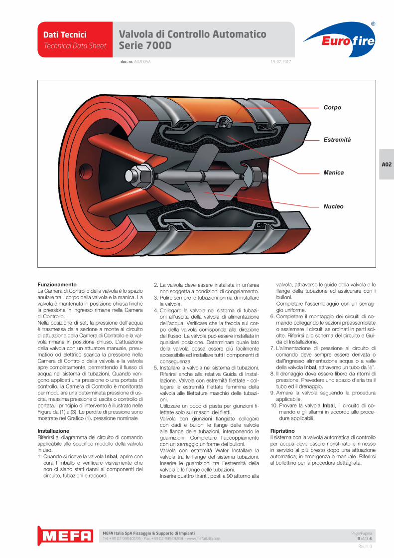
FunzionamentoLa Camera di Controllo della valvola è lo spazio
anulare tra il corpo della valvola e la manica. La
valvola è mantenuta in posizione chiusa fi nchè
la pressione in ingresso rimane nella Camera
di Controllo.
Nella posizione di set, la pressione dell’acqua
è trasmessa dalla sezione a monte al circuito
di attuazione della Camera di Controllo e la val-
vola rimane in posizione chiuso. L’attuazione
della valvola con un attuatore manuale, pneu-
matico od elettrico scarica la pressione nella
Camera di Controllo della valvola e la valvola
apre completamente, permettendo il fl usso di
acqua nel sistema di tubazioni. Quando ven-
gono applicati una pressione o una portata di
controllo, la Camera di Controllo è monitorata
per modulare una determinata pressione di us-
cita, massima pressione di uscita o controllo di
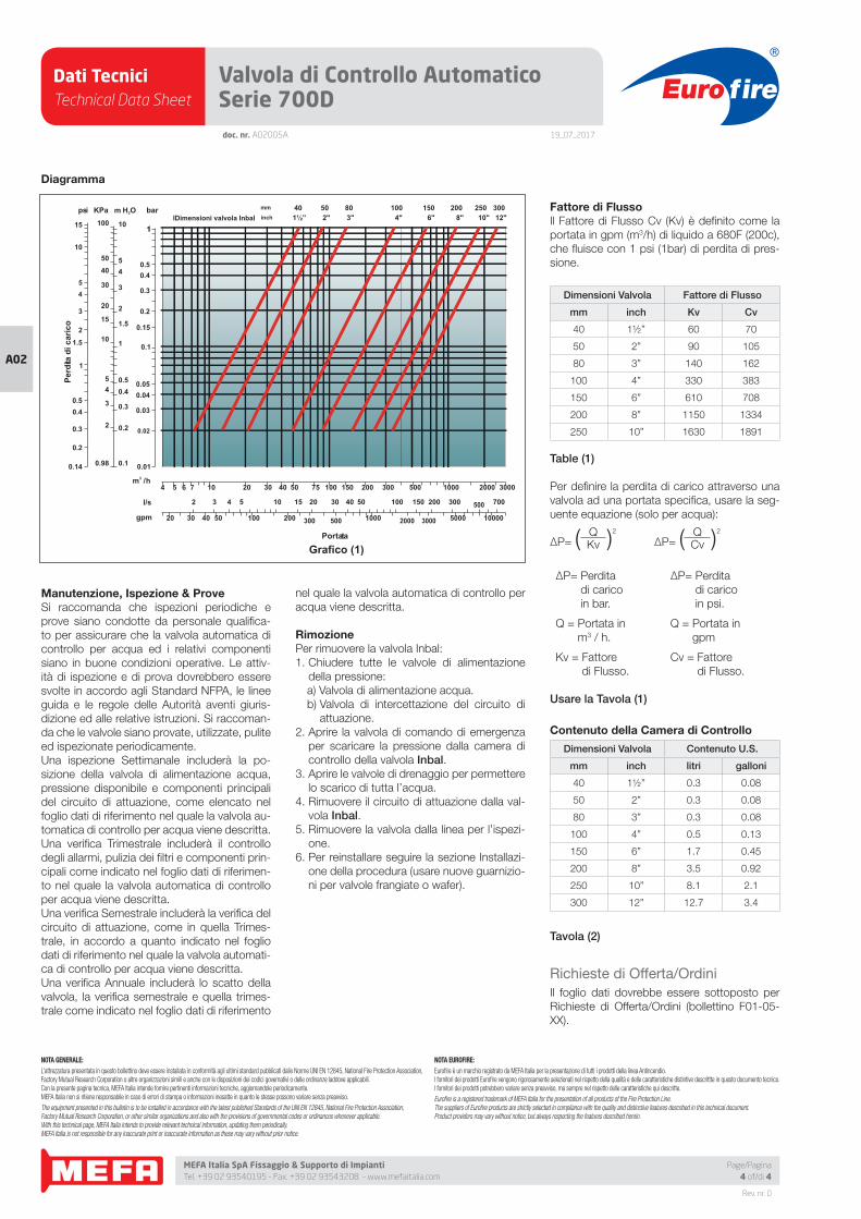
portata.Il principio di intervento è illustrato nelle
Figure da (1) a (3). Le perdite di pressione sono
mostrate nel Grafi co (1). pressione nominale
InstallazioneRiferirsi al diagramma del circuito di comando
applicabile allo specifi co modello della valvola
in uso.
1. Quando si riceve la valvola Inbal, aprire con
cura l’imballo e verifi care visivamente che
non ci siano stati danni ai componenti del
circuito, tubazioni e raccordi.
2. La valvola deve essere installata in un’area
non soggetta a condizioni di congelamento.
3. Pulire sempre le tubazioni prima di installare
la valvola.
4. Collegare la valvola nel sistema di tubazi-
oni all’uscita della valvola di alimentazione
dell’acqua. Verifi care che la freccia sul cor-
po della valvola corrisponda alla direzione
del fl usso. La valvola può essere installata in
qualsiasi posizione. Determinare quale lato
della valvola possa essere più facilmente
accessibile ed installare tutti i componenti di
conseguenza.
5. Installare la valvola nel sistema di tubazioni.
Riferirsi anche alla relativa Guida di Instal-
lazione. Valvola con estremità fi lettate - col-
legare le estremità fi lettate femmina della
valvola alle fi lettature maschio delle tubazi-
oni.
Utilizzare un poco di pasta per giunzioni fi -
lettate solo sui maschi dei fi letti.
Valvola con giunzioni fl angiate collegare
con dadi e bulloni le fl ange delle valvole
alle fl ange delle tubazioni, interponendo le
guarnizioni. Completare l’accoppiamento
con un serraggio uniforme dei bulloni.
Valvola con estremità Wafer Installare la
valvola tra le fl ange del sistema tubazioni.
Inserire le guarnizioni tra l’estremità della
valvola e le fl ange delle tubazioni.
Inserire quattro tiranti, posti a 90 attorno alla
valvola, attraverso le guide della valvola e le
fl ange della tubazione ed assicurare con i
bulloni.
Completare l’assemblaggio con un serrag-
gio uniforme.
6. Completare il montaggio dei circuiti di co-
mando collegando le sezioni preassemblate
o assiemare il circuiti se ordinati in parti sci-
olte. Riferirsi allo schema del circuito e Gui-
da di Installazione.
7. L’alimentazione di pressione al circuito di
comando deve sempre essere derivata o
dall’ingresso alimentazione acqua o a valle
della valvola Inbal, attraverso un tubo da ½”.
8. Il drenaggio deve essere libero da ritorni di
pressione. Prevedere uno spazio d’aria tra il
tubo ed il drenaggio.
9. Armare la valvola seguendo la procedura
applicabile.
10. Provare la valvola Inbal, il circuito di co-
mando e gli allarmi in accordo alle proce-
dure applicabili.
RipristinoIl sistema con la valvola automatica di controllo
per acqua deve essere ripristinato e rimesso
in servizio al più presto dopo una attuazione
automatica, in emergenza o manuale. Riferirsi
al bollettino per la procedura dettagliata.
Nucleo
Manica
Corpo
Estremità
Dati TecniciTechnical Data Sheet
19_07_2017
Euro fire
MEFA Italia SpA Fissaggio & Supporto di Impianti Tel. +39 02 93540195 - Fax. +39 02 93543208 - www.mefaitalia.com
NOTA GENERALE:
L’attrezzatura presentata in questo bollettino deve essere installata in conformità agli ultimi standard pubblicati dalle Norme UNI EN 12845, National Fire Protection Association, Factory Mutual Research Corporation o altre organizzazioni simili e anche con le disposizioni dei codici governativi o delle ordinanze laddove applicabili.Con la presente pagina tecnica, MEFA Italia intende fornire pertinenti informazioni tecniche, aggiornandole periodicamente.MEFA Italia non si ritiene responsabile in caso di errori di stampa o informazioni inesatte in quanto le stesse possono variare senza preavviso.
The equipment presented in this bulletin is to be installed in accordance with the latest published Standards of the UNI EN 12845, National Fire Protection Association, Factory Mutual Research Corporation, or other similar organizations and also with the provisions of governmental codes or ordinances whenever applicable.With this technical page, MEFA Italia intends to provide relevant technical information, updating them periodically.MEFA Italia is not responsible for any inaccurate print or inaccurate information as these may vary without prior notice.
NOTA EUROFIRE:
Eurofi re è un marchio registrato da MEFA Italia per la presentazione di tutti i prodotti della linea Antincendio.I fornitori dei prodotti Eurofi re vengono rigorosamente selezionati nel rispetto della qualità e delle caratteristiche distintive descrittte in questo documento tecnico.I fornitori dei prodotti potrebbero variare senza preavviso, ma sempre nel rispetto delle caratteristiche qui descritte.
Eurofi re is a registered trademark of MEFA Italia for the presentation of all products of the Fire Protection Line.The suppliers of Eurofi re products are strictly selected in compliance with the quality and distinctive features described in this technical document.Product providers may vary without notice, but always respecting the features described herein.
Rev. nr. 0
A02A02
Page/Pagina4 of/di 4
Valvola di Controllo Automatico Serie 700Ddoc. nr. A02005A
Manutenzione, Ispezione & ProveSi raccomanda che ispezioni periodiche e
prove siano condotte da personale qualifi ca-
to per assicurare che la valvola automatica di
controllo per acqua ed i relativi componenti
siano in buone condizioni operative. Le attiv-
ità di ispezione e di prova dovrebbero essere
svolte in accordo agli Standard NFPA, le linee
guida e le regole delle Autorità aventi giuris-
dizione ed alle relative istruzioni. Si raccoman-
da che le valvole siano provate, utilizzate, pulite
ed ispezionate periodicamente.
Una ispezione Settimanale includerà la po-
sizione della valvola di alimentazione acqua,
pressione disponibile e componenti principali
del circuito di attuazione, come elencato nel
foglio dati di riferimento nel quale la valvola au-
tomatica di controllo per acqua viene descritta.
Una verifi ca Trimestrale includerà il controllo
degli allarmi, pulizia dei fi ltri e componenti prin-
cipali come indicato nel foglio dati di riferimen-
to nel quale la valvola automatica di controllo
per acqua viene descritta.
Una verifi ca Semestrale includerà la verifi ca del
circuito di attuazione, come in quella Trimes-
trale, in accordo a quanto indicato nel foglio
dati di riferimento nel quale la valvola automati-
ca di controllo per acqua viene descritta.
Una verifi ca Annuale includerà lo scatto della
valvola, la verifi ca semestrale e quella trimes-
trale come indicato nel foglio dati di riferimento
nel quale la valvola automatica di controllo per
acqua viene descritta.
RimozionePer rimuovere la valvola Inbal:
1. Chiudere tutte le valvole di alimentazione
della pressione:
a) Valvola di alimentazione acqua.
b) Valvola di intercettazione del circuito di
attuazione.
2. Aprire la valvola di comando di emergenza
per scaricare la pressione dalla camera di
controllo della valvola Inbal.3. Aprire le valvole di drenaggio per permettere
lo scarico di tutta l’acqua.
4. Rimuovere il circuito di attuazione dalla val-
vola Inbal.5. Rimuovere la valvola dalla linea per l’ispezi-
one.
6. Per reinstallare seguire la sezione Installazi-
one della procedura (usare nuove guarnizio-
ni per valvole frangiate o wafer).
Fattore di FlussoIl Fattore di Flusso Cv (Kv) è defi nito come la
portata in gpm (m3/h) di liquido a 680F (200c),
che fl uisce con 1 psi (1bar) di perdita di pres-
sione.
Dimensioni Valvola Fattore di Flusso
mm inch Kv Cv
40 1½’’ 60 70
50 2” 90 105
80 3” 140 162
100 4” 330 383
150 6” 610 708
200 8” 1150 1334
250 10” 1630 1891
Table (1)
Per defi nire la perdita di carico attraverso una
valvola ad una portata specifi ca, usare la seg-
uente equazione (solo per acqua):
ΔP= ( QKv )
2
ΔP= ( QCv )
2
ΔP= Perdita
di carico
in bar.
ΔP= Perdita
di carico
in psi.
Q = Portata in
m3 / h.
Q = Portata in
gpm
Kv = Fattore
di Flusso.
Cv = Fattore
di Flusso.
Usare la Tavola (1)
Contenuto della Camera di Controllo
Dimensioni Valvola Contenuto U.S.
mm inch litri galloni
40 1½’’ 0.3 0.08
50 2” 0.3 0.08
80 3” 0.3 0.08
100 4” 0.5 0.13
150 6” 1.7 0.45
200 8” 3.5 0.92
250 10” 8.1 2.1
300 12” 12.7 3.4
Tavola (2)
Richieste di Offerta/Ordini
Il foglio dati dovrebbe essere sottoposto per
Richieste di Offerta/Ordini (bollettino F01-05-
XX).
Grafico (1)
4 5 6 7 10 20 30 40 50 75 100 200 300 500 1000150 2000 3000
2 3 4 5 10 15 20 30 40 50 100 150 200 300 500 700
20 30 40 50 100 200 1000 2000 3000 5000 10000300 500
6"4"3"2"1½” 12"300
10"250
8"20015010004 05 08
inch
mm
l/s
gpm
3m /h
bar
89.0 1.0
0.2
0.3
0.40.5
3
1 0.1
0.01
0.02
0.03
0.040.05
1.5
2
2
3
45
10
10
15
20
30
4050
100
54
0.15
0.2
0.3
0.40.5
1
psi
0.14
0.3
0.4
0.2
0.5
1
KPa m H O2IDimensioni valvola Inbal
15
10
3
1.5
2
54
Perd
ita d
i car
ico
Portata
Diagramma
Dati TecniciTechnical Data Sheet
19_07_2017
Euro fire
MEFA Italia SpA Fissaggio & Supporto di Impianti Tel. +39 02 93540195 - Fax. +39 02 93543208 - www.mefaitalia.com
Rev. nr. 0
A02
Page/Pagina1 of/di 2
doc. nr. A02006A
Deluge Systems
TEST VALVE
TEST VALVE
ALARMALARM
TO "O "
FIIN CAS F
AN
OPEN RANANTURNTURNTOTO
"O"O
FIFI
TEST VALVE
TEST VALVE
ALARMALARM
DELUGDELUGVALVEVALVE
INBALINBAL
TURN DLE
TURN DLETO "O "
TO "O "
FIFIIN CAS F
IN CAS F
ANAN
OPEN R
OPEN R
Dati TecniciTechnical Data Sheet
19_07_2017
Euro fire
MEFA Italia SpA Fissaggio & Supporto di Impianti Tel. +39 02 93540195 - Fax. +39 02 93543208 - www.mefaitalia.com
NOTA GENERALE:
L’attrezzatura presentata in questo bollettino deve essere installata in conformità agli ultimi standard pubblicati dalle Norme UNI EN 12845, National Fire Protection Association, Factory Mutual Research Corporation o altre organizzazioni simili e anche con le disposizioni dei codici governativi o delle ordinanze laddove applicabili.Con la presente pagina tecnica, MEFA Italia intende fornire pertinenti informazioni tecniche, aggiornandole periodicamente.MEFA Italia non si ritiene responsabile in caso di errori di stampa o informazioni inesatte in quanto le stesse possono variare senza preavviso.
The equipment presented in this bulletin is to be installed in accordance with the latest published Standards of the UNI EN 12845, National Fire Protection Association, Factory Mutual Research Corporation, or other similar organizations and also with the provisions of governmental codes or ordinances whenever applicable.With this technical page, MEFA Italia intends to provide relevant technical information, updating them periodically.MEFA Italia is not responsible for any inaccurate print or inaccurate information as these may vary without prior notice.
NOTA EUROFIRE:
Eurofi re è un marchio registrato da MEFA Italia per la presentazione di tutti i prodotti della linea Antincendio.I fornitori dei prodotti Eurofi re vengono rigorosamente selezionati nel rispetto della qualità e delle caratteristiche distintive descrittte in questo documento tecnico.I fornitori dei prodotti potrebbero variare senza preavviso, ma sempre nel rispetto delle caratteristiche qui descritte.
Eurofi re is a registered trademark of MEFA Italia for the presentation of all products of the Fire Protection Line.The suppliers of Eurofi re products are strictly selected in compliance with the quality and distinctive features described in this technical document.Product providers may vary without notice, but always respecting the features described herein.
Rev. nr. 0
A02
doc. nr. A02006A
Deluge Systems
Page/Pagina2 of/di 2
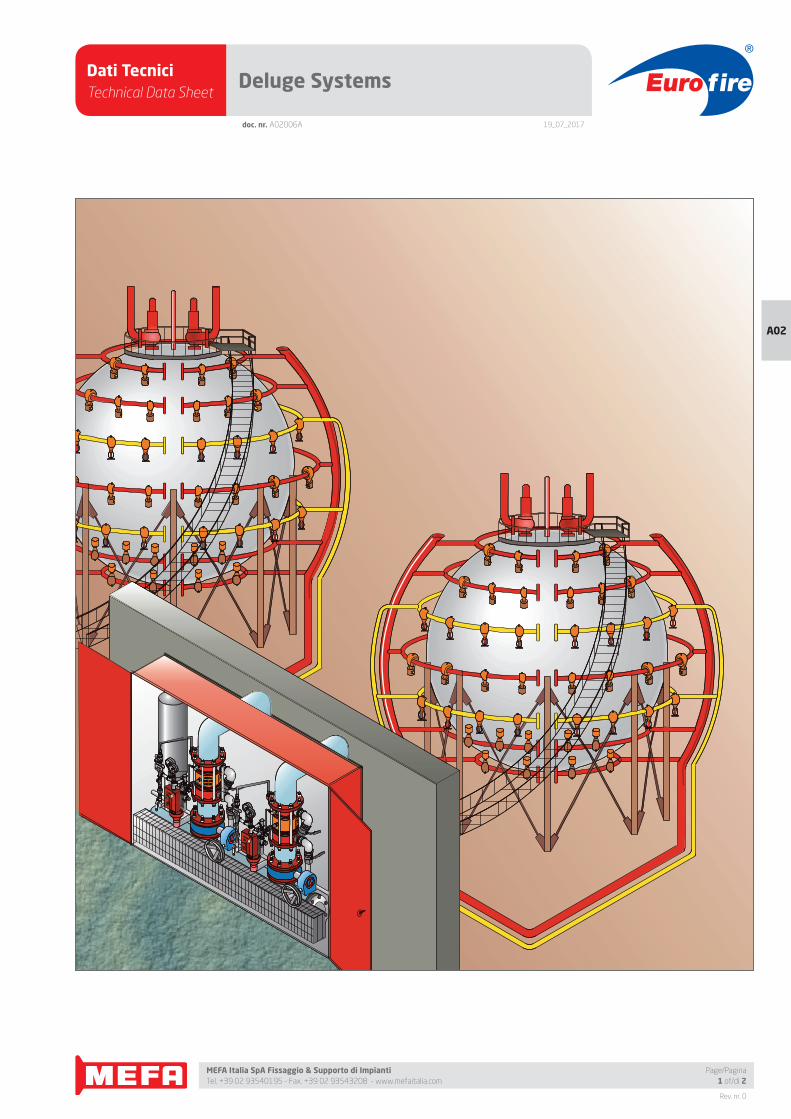
A Deluge System is a sprinkler piping system employing open sprinklers
or nozzles, connected to a water supply through a deluge valve which is
closed when in set position.
There is no water in the sprinkler system pipe, and it is at atmospheric
pressure. A supplemental detection system is provided throughout the
same area as the sprinkler system.
The deluge valve is operated manually or automatically by actuation of
the detection and release systems. When the deluge valve opens, water
fl ows into the piping system and discharges from all open sprinklers and/
or nozzles in the system.
In the foam-water deluge system, when the deluge valve opens, water
fl ows into the piping system. Foam concentrate [protein, fl uoroprotein,
or aqueous fi lm forming foam (AFFF)] is injected into the water, and the
resulting foam solution through all sprinklers and spray nozzles simulta-
neously generates and distributes foam.
Deluge systems, as the name implies, are intended to deliver large quan-
tities of water over a large area in a relatively short period of time. Deluge
systems are suitable for facilities that contain combustible or fl ammable
materials. In addition, these systems are used for situations in which
thermal damage is likely to occur in a relatively short period of time.
Foam-water deluge systems are especially applicable in the protection of
most fl ammable liquid hazards.
Deluge Systems are used for the purpose of:
• Extinguishing fi re in the protected area by discharging suitable
foam-solution densities, the use of selected discharge devices, and
by provision of adequate supplies of air-water at suffi cient pressures.
• Prevention of fi re in the protected area by manual operation of the
deluge valve to discharge foam or water in case of accumulation of
hazardous materials from spills to afford protection against ignition in
such occupancies as garages, aircraft hangars, petrochemical plants,
paint and varnish plants, or from other causes in the protected area.
• Control of fi re to allow controlled burning of fl ammable and combustible
materials where extinguishment is not practical. Exposure protection
to reduce heat transfer to neighboring high hazardous areas can be
accomplished by water spray or foam.
Water supplies for deluge systems shall be of fl ow capacity and pressure
capable of maintaining foam or water discharge or both, at the design
rate for the required period of discharge, over the entire area. Since del-
uge systems produce a large volume of water, a proper drainage system
should be provided in the protected area.
Eurofi re Deluge Valves are available for:
Local Resetting - Once the deluge valve operates, it is latched in an open
position and will not close even if the releasing device closes. The deluge
valve will close only if the Local Resetting procedure, applicable to the
specifi c Eurofi re Deluge Valve in use, is exercised.In the design of the
Local resetting Eurofi re Deluge Valve, priority was given to fast and easy
reset after testing or emergency operation.
Remote Resetting - The Eurofi re Deluge Valve can be remotely reset. The
remote resetting enables quick resetting from the control panel or control
room for areas which no longer need to be fi re extinguished or cooled.
Thus, the water resources are effectively used only in the areas which are
still under emergency conditions.
The Eurofi re Deluge Valve is designed to allow for a variety of detection
and release systems:
Hydraulic Actuation - A wet pilot line contains water under pressure and
functions as thermal detecting and releasing device. A manual emergen-
cy valve can provide, besides automatic actuation, remote and/or local
manual operation.
Hydraulic actuation is the simplest and least expensive release system.
Pneumatic Actuation - A dry pilot line contains air or gas under pres-
sure, functioning as a thermal detecting and a releasing device. A manual
emergency valve can provide, besides automatic actuation, remote and/
or local manual operation. Installation and maintenance are usually more
costly than Hydraulic Actuation. To reduce operation time, an optional
accelerator may be considered. However, the Eurofi re Pneumatic Actua-
tors are designed for operation at a minimal pressure drop of the dry pilot
line, regardless of the water line pressure level.
Electric Actuation - The electric detection system consists of heat,
smoke, fl ame, or radiative detectors and communicates electrically with
a control panel. The releasing device normally consists of a solenoid
valve, which could be of power-to-open type (a back-up power source
may be considered), power-to-close type (solenoid is under power in set
position), or magnetic latch (impulse) type (selfmaintained position from
the last control signal of a millisecond duration). A remote manual electric
operation and local hydraulic manual operation are normally included.
Installation and maintenance are usually more costly than hydraulic or
pneumatic control.
Any combination of hydraulic, pneumatic, and/or electric actuation ar-
ranged as non-interlocked or double interlocked is available. One of the
most popular in the industry is:
Pneu-Electric Actuation - A combination of pneumatic and electric ac-
tuation designed as non-interlocked action. The Eurofi re Deluge Valve
will open either by operation of the dry pilot line or the electric detection
system.
A pressure control added feature is available on each of the actuation
types (see section F06).
Besides the types of deluge valves included in this book, there are many
other variations as well as customized deluge valves to answer specifi c
requirements for functional and operational conditions.
Dati TecniciTechnical Data Sheet
19_07_2017
Euro fire
MEFA Italia SpA Fissaggio & Supporto di Impianti Tel. +39 02 93540195 - Fax. +39 02 93543208 - www.mefaitalia.com
Rev. nr. 0
A02
Page/Pagina1 of/di 4
doc. nr. A02007A
Deluge Valve, Electric Actuation Series 700D/DX
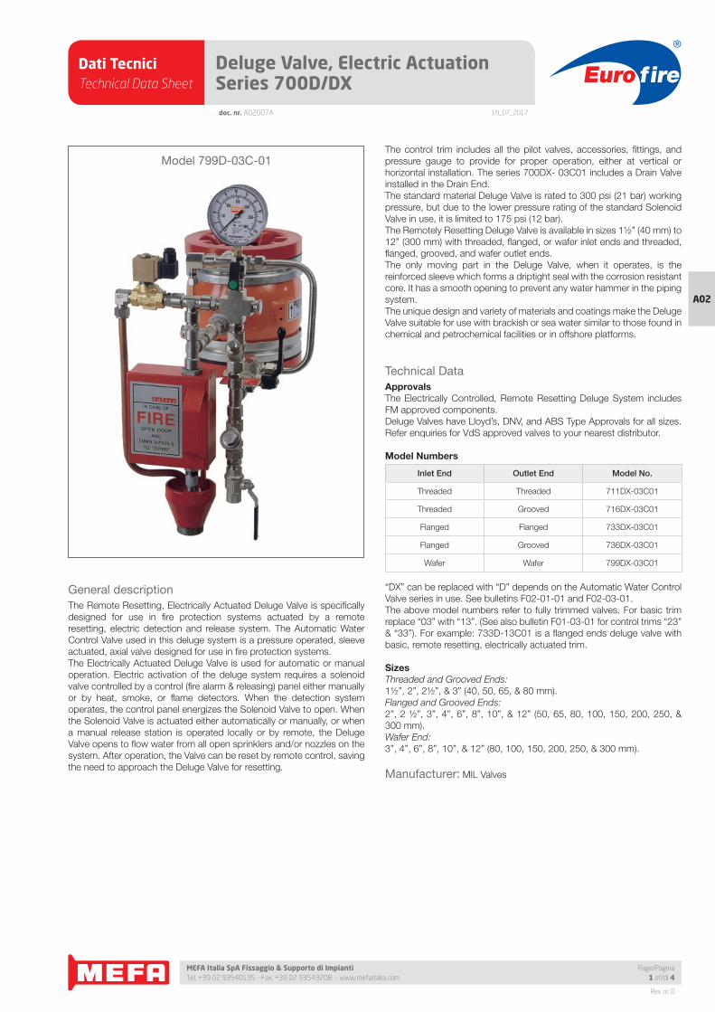
General description
The Remote Resetting, Electrically Actuated Deluge Valve is specifi cally
designed for use in fi re protection systems actuated by a remote
resetting, electric detection and release system. The Automatic Water
Control Valve used in this deluge system is a pressure operated, sleeve
actuated, axial valve designed for use in fi re protection systems.
The Electrically Actuated Deluge Valve is used for automatic or manual
operation. Electric activation of the deluge system requires a solenoid
valve controlled by a control (fi re alarm & releasing) panel either manually
or by heat, smoke, or fl ame detectors. When the detection system
operates, the control panel energizes the Solenoid Valve to open. When
the Solenoid Valve is actuated either automatically or manually, or when
a manual release station is operated locally or by remote, the Deluge
Valve opens to fl ow water from all open sprinklers and/or nozzles on the
system. After operation, the Valve can be reset by remote control, saving
the need to approach the Deluge Valve for resetting.
The control trim includes all the pilot valves, accessories, fi ttings, and
pressure gauge to provide for proper operation, either at vertical or
horizontal installation. The series 700DX- 03C01 includes a Drain Valve
installed in the Drain End.
The standard material Deluge Valve is rated to 300 psi (21 bar) working
pressure, but due to the lower pressure rating of the standard Solenoid
Valve in use, it is limited to 175 psi (12 bar).
The Remotely Resetting Deluge Valve is available in sizes 1½” (40 mm) to
12” (300 mm) with threaded, fl anged, or wafer inlet ends and threaded,
fl anged, grooved, and wafer outlet ends.
The only moving part in the Deluge Valve, when it operates, is the
reinforced sleeve which forms a driptight seal with the corrosion resistant
core. It has a smooth opening to prevent any water hammer in the piping
system.
The unique design and variety of materials and coatings make the Deluge
Valve suitable for use with brackish or sea water similar to those found in
chemical and petrochemical facilities or in offshore platforms.
Technical Data
ApprovalsThe Electrically Controlled, Remote Resetting Deluge System includes
FM approved components.
Deluge Valves have Lloyd’s, DNV, and ABS Type Approvals for all sizes.
Refer enquiries for VdS approved valves to your nearest distributor.
Model Numbers
Inlet End Outlet End Model No.
Threaded Threaded 711DX-03C01
Threaded Grooved 716DX-03C01
Flanged Flanged 733DX-03C01
Flanged Grooved 736DX-03C01
Wafer Wafer 799DX-03C01
“DX” can be replaced with “D” depends on the Automatic Water Control
Valve series in use. See bulletins F02-01-01 and F02-03-01.
The above model numbers refer to fully trimmed valves. For basic trim
replace “03” with “13”. (See also bulletin F01-03-01 for control trims “23”
& “33”). For example: 733D-13C01 is a fl anged ends deluge valve with
basic, remote resetting, electrically actuated trim.
SizesThreaded and Grooved Ends:
1½”, 2”, 2½”, & 3” (40, 50, 65, & 80 mm).
Flanged and Grooved Ends:
2”, 2 ½”, 3”, 4”, 6”, 8”, 10”, & 12” (50, 65, 80, 100, 150, 200, 250, &
300 mm).
Wafer End:
3”, 4”, 6”, 8”, 10”, & 12” (80, 100, 150, 200, 250, & 300 mm).
Manufacturer: MIL Valves
Model 799D-03C-01
Dati TecniciTechnical Data Sheet
19_07_2017
Euro fire
MEFA Italia SpA Fissaggio & Supporto di Impianti Tel. +39 02 93540195 - Fax. +39 02 93543208 - www.mefaitalia.com
Rev. nr. 0
A02
doc. nr. A02007A
Deluge Valve, Electric Actuation Series 700D/DX
Page/Pagina2 of/di 4
End StandardsThreaded End:
NPT or BSPT.
Flanged End:
ANSI B16.5 class 150 & 300 ;
ISO 7005 - PN10, 16 & 25 ;
BS 10 Table D & E ;
AS 2129 Table D & E ;
Jis B 2212; 2213, 2214.
Wafer End:
Fits most of the above standards.
Grooved End:
ANSI/AWWA C606-87.
Pressure RatingMaximum working pressure: 175 psi (12 bar).
Higher working pressure is available depends
on the specifi c solenoid valve in use.
Temperature RangeWater: Max. +1500F (+650C).
Installation PositionVertical or horizontal.
Solenoid ValveAvailable in:
Energized to open, energized to close,
and magnetic latch (impulse) types.
Standard voltages:
AC 50Hz: 24, 48, 110, 220, & 380 volt ;
AC 60Hz: 24, 120, & 240 volt ;
DC: 12, 24, 48, 110, 120, & 220 volt .
Other voltages are available on request.
Protection type Enclosure:
Conforms to NEMA (1 to 9), IEC (79 & 529), or
CENELEC standards (50014 to 50019).
See bulletins F30-10-01; F30-11-01; and F30-
12-01.
MaterialsStandardValve Housing:
Carbon steel (SAE 1021).
Valve Ends and Wafer Drain End:
Ductile Iron (ASTM A536-65 45 12).
Threaded, Flanged, and Grooved Drain Ends:
Carbon steel (SAE 1020).
Sleeve:
SMR5 Elastomer reinforced with Polyester and
Kevlar.
Control Trim:
Brass Nickel Chrome plated, Stainless Steel,
and Galvanized Steel.
OptionalCast Steel ;
Bronze ;
Nickel Aluminum Bronze ;
Stainless Steel AISI 316 ;
Super Austenitic Stainless Steel ;
Super Duplex Stainless Steel ;
Titanium.
CoatingStandard
Powder epoxy coated .Thickness: 0.004” (0.1
mm ) external and internal surfaces.
Optional
High built epoxy coated and polyurethane fi n-
ish. Thickness: 0.01” (0.3 mm).
Halar® coated. Thickness: 0.02” (0.5 mm).
Halar® is a registered trade mark of Ausimont USA Inc.
Control TrimOn standard, the control trim is supplied pre-
assembled in sections. If self assembly is re-
quired, all the trim components are supplied
in loose form.
The complete control trim includes the follow-
ing components:
• Solenoid Valve.
• Trim Shutoff Valve and Drain Valve are quar-
ter turn, ball valves.
• Y- Strainer with stainless steel screen.
• Alarm Test Valve - 3 way, L-port, quarter turn
ball valve.
• Check Valve - spring loaded, soft seat.
• Supply Pressure Gauge with dual scale (psi
and bar).
• Pressure Gauge Valve - 3 way, quarter turn
ball valve.
• Drain Cup and Drain Tubes.
• Automatic Drain Valve.
• Emergency Release Station.
Features• Remote Electric activation and reset enables
effi cient control of the whole area.
• The same deluge valve can be operated and
reset from the control room as well as from
fi eld control panel.
• No Moving Mechanical Part (N.M.M.P.) con-
struction ensures a long life of dependable
operation, reducing the cost of maintenance.
• Quick, yet soft opening performance - elimi-
nates water hammer and Consequent dam-
ages.
• The line pressure is suffi cient to close the
Valve tightly. Can perform also, when water
supply valve is not in use.
• Optional opening and/or closing speed con-
trol is available.
• Fast and easy reset - no need to approach
the valve.
• Supplied standard in almost complete preas-
sembled form - saves the selfassembly cost.
• Can be installed vertically or horizontally.
• Compact design - minimum space for valve
and trim.
• Unique principle of operation prevents false
operation due to water surges.
• Pressure rating of 300 psi (21 bar) provided a
compatible solenoid valve is used.
• Wide selection of solenoid valves to meet
various requirements for type of operation,
voltage, frequency, protection, and enclo-
sure.
• Wide range of sizes for an ideal system de-
sign.
• Control trim made of high grade materials as
standard.
• Epoxy coating supplied as standard ensures
excellent corrosion resistence.
• Variety of available materials to ensure cor-
rosion - free service even under severe con-
ditions.
• Compatible with electric, pneumatic, and/or
hydraulic release with the same basic trim.
• Additional functions such as pressure control
or another release system, could be added
on the same valve body.
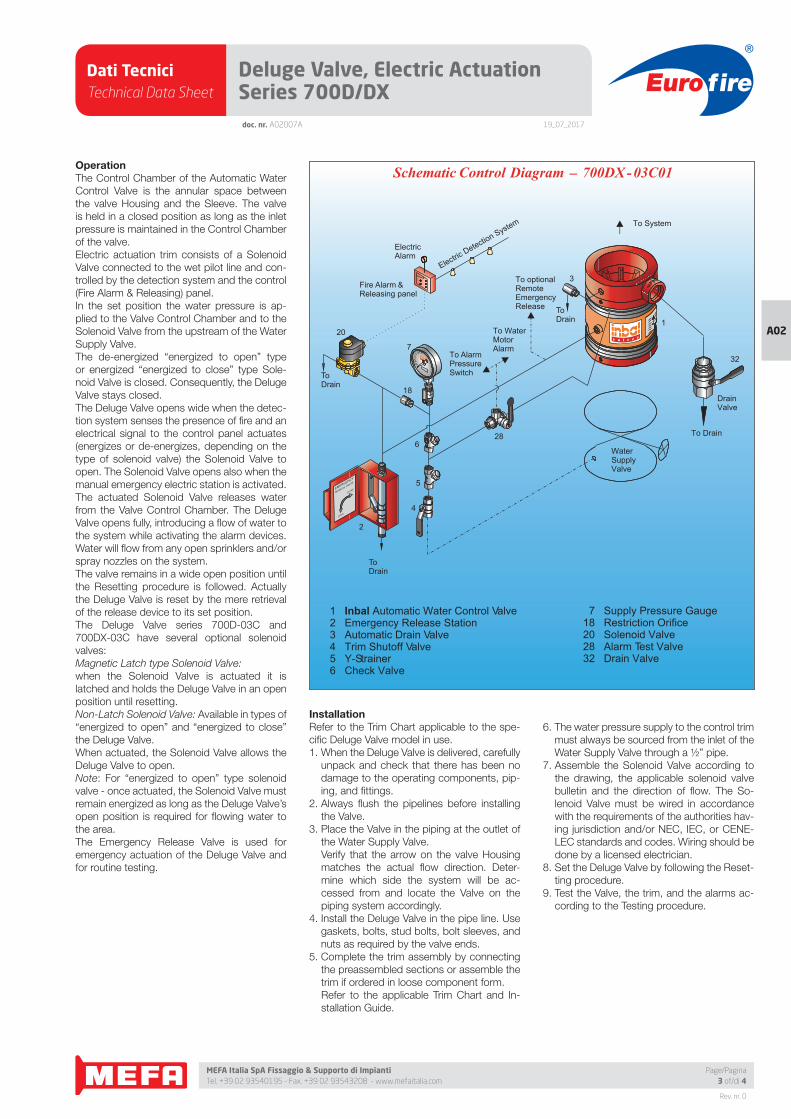
Dati TecniciTechnical Data Sheet
19_07_2017
Euro fire
MEFA Italia SpA Fissaggio & Supporto di Impianti Tel. +39 02 93540195 - Fax. +39 02 93543208 - www.mefaitalia.com
Rev. nr. 0
A02
Page/Pagina3 of/di 4
doc. nr. A02007A
Deluge Valve, Electric Actuation Series 700D/DX
OperationThe Control Chamber of the Automatic Water
Control Valve is the annular space between
the valve Housing and the Sleeve. The valve
is held in a closed position as long as the inlet
pressure is maintained in the Control Chamber
of the valve.
Electric actuation trim consists of a Solenoid
Valve connected to the wet pilot line and con-
trolled by the detection system and the control
(Fire Alarm & Releasing) panel.
In the set position the water pressure is ap-
plied to the Valve Control Chamber and to the
Solenoid Valve from the upstream of the Water
Supply Valve.
The de-energized “energized to open” type
or energized “energized to close” type Sole-
noid Valve is closed. Consequently, the Deluge
Valve stays closed.
The Deluge Valve opens wide when the detec-
tion system senses the presence of fi re and an
electrical signal to the control panel actuates
(energizes or de-energizes, depending on the
type of solenoid valve) the Solenoid Valve to
open. The Solenoid Valve opens also when the
manual emergency electric station is activated.
The actuated Solenoid Valve releases water
from the Valve Control Chamber. The Deluge
Valve opens fully, introducing a fl ow of water to
the system while activating the alarm devices.
Water will fl ow from any open sprinklers and/or
spray nozzles on the system.
The valve remains in a wide open position until
the Resetting procedure is followed. Actually
the Deluge Valve is reset by the mere retrieval
of the release device to its set position.
The Deluge Valve series 700D-03C and
700DX-03C have several optional solenoid
valves:
Magnetic Latch type Solenoid Valve:
when the Solenoid Valve is actuated it is
latched and holds the Deluge Valve in an open
position until resetting.
Non-Latch Solenoid Valve: Available in types of
“energized to open” and “energized to close”
the Deluge Valve.
When actuated, the Solenoid Valve allows the
Deluge Valve to open.
Note: For “energized to open” type solenoid
valve - once actuated, the Solenoid Valve must
remain energized as long as the Deluge Valve’s
open position is required for fl owing water to
the area.
The Emergency Release Valve is used for
emergency actuation of the Deluge Valve and
for routine testing.
InstallationRefer to the Trim Chart applicable to the spe-
cifi c Deluge Valve model in use.
1. When the Deluge Valve is delivered, carefully
unpack and check that there has been no
damage to the operating components, pip-
ing, and fi ttings.
2. Always fl ush the pipelines before installing
the Valve.
3. Place the Valve in the piping at the outlet of
the Water Supply Valve.
Verify that the arrow on the valve Housing
matches the actual fl ow direction. Deter-
mine which side the system will be ac-
cessed from and locate the Valve on the
piping system accordingly.
4. Install the Deluge Valve in the pipe line. Use
gaskets, bolts, stud bolts, bolt sleeves, and
nuts as required by the valve ends.
5. Complete the trim assembly by connecting
the preassembled sections or assemble the
trim if ordered in loose component form.
Refer to the applicable Trim Chart and In-
stallation Guide.
6. The water pressure supply to the control trim
must always be sourced from the inlet of the
Water Supply Valve through a ½” pipe.
7. Assemble the Solenoid Valve according to
the drawing, the applicable solenoid valve
bulletin and the direction of fl ow. The So-
lenoid Valve must be wired in accordance
with the requirements of the authorities hav-
ing jurisdiction and/or NEC, IEC, or CENE-
LEC standards and codes. Wiring should be
done by a licensed electrician.
8. Set the Deluge Valve by following the Reset-
ting procedure.
9. Test the Valve, the trim, and the alarms ac-
cording to the Testing procedure.
7 Supply Pressure Gauge18 Restriction Orifice20 Solenoid Valve28 Alarm Test Valve32 Drain Valve
1 Inbal Automatic Water Control Valve2 Emergency Release Station3 Automatic Drain Valve4 Trim Shutoff Valve5 Y-Strainer6 Check Valve
Electric Detection System To System
Fire Alarm & Releasing panel
ToDrain
ToDrain
To optionalRemoteEmergencyRelease
To AlarmPressureSwitch
To WaterMotorAlarm
ElectricAlarm
ToDrain
WaterSupplyValve
OUT
To Drain
DrainValve
4
5
7
3
628
2
20
18
32
1
_Schematic Control Diagram 700DX -03C01
OPEN
CLOSEEMERGENCY
MANUAL VALVE
Dati TecniciTechnical Data Sheet
19_07_2017
Euro fire
MEFA Italia SpA Fissaggio & Supporto di Impianti Tel. +39 02 93540195 - Fax. +39 02 93543208 - www.mefaitalia.com
NOTA GENERALE:
L’attrezzatura presentata in questo bollettino deve essere installata in conformità agli ultimi standard pubblicati dalle Norme UNI EN 12845, National Fire Protection Association, Factory Mutual Research Corporation o altre organizzazioni simili e anche con le disposizioni dei codici governativi o delle ordinanze laddove applicabili.Con la presente pagina tecnica, MEFA Italia intende fornire pertinenti informazioni tecniche, aggiornandole periodicamente.MEFA Italia non si ritiene responsabile in caso di errori di stampa o informazioni inesatte in quanto le stesse possono variare senza preavviso.
The equipment presented in this bulletin is to be installed in accordance with the latest published Standards of the UNI EN 12845, National Fire Protection Association, Factory Mutual Research Corporation, or other similar organizations and also with the provisions of governmental codes or ordinances whenever applicable.With this technical page, MEFA Italia intends to provide relevant technical information, updating them periodically.MEFA Italia is not responsible for any inaccurate print or inaccurate information as these may vary without prior notice.
NOTA EUROFIRE:
Eurofi re è un marchio registrato da MEFA Italia per la presentazione di tutti i prodotti della linea Antincendio.I fornitori dei prodotti Eurofi re vengono rigorosamente selezionati nel rispetto della qualità e delle caratteristiche distintive descrittte in questo documento tecnico.I fornitori dei prodotti potrebbero variare senza preavviso, ma sempre nel rispetto delle caratteristiche qui descritte.
Eurofi re is a registered trademark of MEFA Italia for the presentation of all products of the Fire Protection Line.The suppliers of Eurofi re products are strictly selected in compliance with the quality and distinctive features described in this technical document.Product providers may vary without notice, but always respecting the features described herein.
Rev. nr. 0
A02
Page/Pagina4 of/di 4
Deluge Valve, Electric Actuation Series 700D/DXdoc. nr. A02007A
ResettingThe Deluge Valve system must be reset and
restored to service as soon as possible after
automatic, emergency, or manual actuation.
1. After automatic or manual electric operation
- reset the detection system, Fire Alarm &
Releasing Panel, and the Solenoid Valve.
The Deluge Valve will close drip tight. Elec-
tric Alarm and water fl ow alarms are reset.
Verify that the supply pressure has been re-
stored to the normal level.
2. After manual emergency operation - close
the Emergency Release Valve.
The Deluge Valve will close drip tight.
The water fl ow alarm is reset.
Verify that the supply pressure has been re-
stored to the normal level.
In either one of the operations exercised, the
system piping should be drained.
Maintenance, Inspection, & TestingIt is recommended that periodic inspections
and tests be conducted by qualifi ed person-
nel to ensure that the Deluge Valve and related
equipment are in good operating condition.
The inspection and testing activities should
be done according to NFPA Standards, the
guidelines and regulations of the authorities
having jurisdiction, and the following instruc-
tions. It is recommended that the Deluge Valve
be tested, operated, cleaned, and inspected
at least on a routine basis.
InspectionA weekly Inspection is recommended:
1. Verify that the Water Supply Valve is sealed
in a full open position.
2. Verify that the required water pressure is
being applied to the Deluge Valve inlet and
trim.
3. Verify that the Trim Shutoff Valve, Alarm Test
Valve, Emergency Release Valve, Pressure
Gauge Valve, and Drain Valve (if in use) are
in set position.
4. The Supply Pressure Gauge should be
checked for accuracy.
5. Visually inspect for disconnected wires, bro-
ken or missing parts, or other evidence of
impaired protection.
Strainer CleaningA quarterly Strainer Cleaning is recommended:
1. Close the Trim Shutoff Valve.
2. Remove the covers of the trim and alarm
Y- Strainer. Clean if necessary.
3. Open the Trim Shutoff Valve.
Alarm TestingA quarterly Alarm Testing is recommended:
1. Test the Water Motor Alarm or Alarm Pres-
sure Switch by opening the Alarm Test
Valve.
2. Water Motor Alarm should be audible.
Alarm Pressure Switch should activate.
3. Close the Alarm Test Valve. All local alarms
stop sounding and pressure switch is reset.
4. Verify that supply piping to alarm drains
properly.
Deluge Trim TestingA semi-annual Deluge Trim Testing is recom-
mended. Testing of the control trim is conduct-
ed with no fl ow of water to the system.
1. Close the Water Supply Valve installed in the
inlet of the Deluge Valve.
2. Actuate the Solenoid Valve.
Verify that water is drained from the deluge
trim which simulates an open position of the
Deluge Valve.
3. Reset the valve by performing the instruc-
tions in Resetting.
4. Open the Water Supply Valve.
Trip TestingAn annual Trip Testing is recommended.
Performing the Trip Testing will cause water to
fl ow from all open sprinklers and/or nozzles.
Prevent damage by taking the necessary pre-
cautions.
1. Trip the Deluge Valve to open by either:
a) Actuation of the Solenoid Valve.
b) Opening the Emergency Release Valve.
The water in the Valve Control Chamber is
allowed to vent to the atmosphere. The Del-
uge Valve will open and water will fl ow to the
system.
2. All the alarms should operate. Verify that the
whole system is working properly.
3. Reset the system by performing the instruc-
tions in Resetting.
4. Verify that water supply pressure is restored
to the normal level.
RemovalTo remove the Deluge Valve:
1. Close all the pressure supply valves:
a) Water Supply Valves.
b) Trim Shutoff Valve.
2. Disconnect the electric wires from the
Solenoid Valve. The electric work should be
done by a licensed electrician.
3. Open the Emergency Release Valve to re-
lease the water pressure from the Valve
Control Chamber.
4. Open the Drain Valve to allow all the water
to drain.
5. Disconnect the union and remove the trim
from the valve.
6. Remove the Valve from the line for inspec-
tion.
7. To reinstall, follow the Installation procedure
(use new gaskets for fl anged or wafer valve).
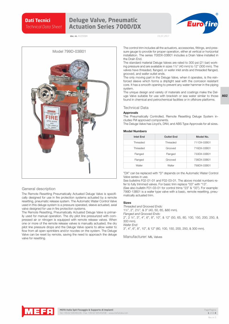
Dati TecniciTechnical Data Sheet
19_07_2017
Euro fire
MEFA Italia SpA Fissaggio & Supporto di Impianti Tel. +39 02 93540195 - Fax. +39 02 93543208 - www.mefaitalia.com
Rev. nr. 0
A02
Page/Pagina1 of/di 4
doc. nr. A02008A
Deluge Valve, Pneumatic Actuation Series 700D/DX
General description
The Remote Resetting Pneumatically Actuated Deluge Valve is specifi -
cally designed for use in fi re protection systems actuated by a remote
resetting, pneumatic release system. The Automatic Water Control Valve
used in this deluge system is a pressure operated, sleeve actuated, axial
valve designed for use in fi re protection systems.
The Remote Resetting, Pneumatically Actuated Deluge Valve is primar-
ily used for manual operation. The dry pilot line pressurized with com-
pressed air or nitrogen is equipped with remote release valves. When
one or more of the remote release valves is manually actuated, the dry
pilot line pressure drops and the Deluge Valve opens to allow water to
fl ow from all open sprinklers and/or nozzles on the system. The Deluge
Valve can be reset by remote, saving the need to approach the deluge
valve for resetting.
The control trim includes all the actuators, accessories, fi ttings, and pres-
sure gauge to provide for proper operation, either at vertical or horizontal
installation. The series 700DX-03B01 includes a Drain Valve installed in
the Drain End.
The standard material Deluge Valves are rated to 300 psi (21 bar) work-
ing pressure and are available in sizes 1½” (40 mm) to 12” (300 mm). The
valves have threaded, fl anged, or wafer inlet ends and threaded fl anged,
grooved, and wafer outlet ends.
The only moving part in the Deluge Valve, when it operates, is the rein-
forced sleeve which forms a driptight seal with the corrosion resistant
core. It has a smooth opening to prevent any water hammer in the piping
system.
The unique design and variety of materials and coatings make the Del-
uge Valve suitable for use with brackish or sea water similar to those
found in chemical and petrochemical facilities or in offshore platforms.
Technical Data
ApprovalsThe Pneumatically Controlled, Remote Resetting Deluge System in-
cludes FM approved components.
The Deluge Valve has Lloyd’s, DNV, and ABS Type Approvals for all sizes.
Model Numbers
Inlet End Outlet End Model No.
Threaded Threaded 711DX-03B01
Threaded Grooved 716DX-03B01
Flanged Flanged 733DX-03B01
Flanged Grooved 736DX-03B01
Wafer Wafer 799DX-03B01
”DX” can be replaced with “D” depends on the Automatic Water Control
Valve series in use.
See bulletins F02-01-01 and F02-03-01. The above model numbers re-
fer to fully trimmed valves. For basic trim replace “03” with “13”.
(See also bulletin F01-03-01 for control trims “23” & “33”). For example:
799D-13B01 is a wafer type valve with a basic, remote resetting, pneu-
matically actuated trim.
SizesThreaded and Grooved Ends:
1½”, 2”, 2½”, & 3” (40, 50, 65, &80 mm).
Flanged and Grooved Ends:
2”, 2 ½”, 3”, 4”, 6”, 8”, 10”, & 12” (50, 65, 80, 100, 150, 200, 250, &
300 mm).
Wafer End:
3”, 4”, 6”, 8”, 10”, & 12” (80, 100, 150, 200, 250, & 300 mm).
Manufacturer: MIL Valves
Model 799D-03B01
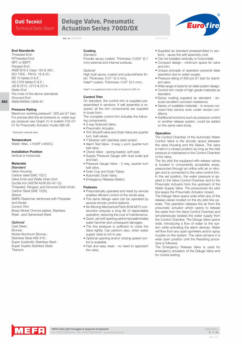
Dati TecniciTechnical Data Sheet
19_07_2017
Euro fire
MEFA Italia SpA Fissaggio & Supporto di Impianti Tel. +39 02 93540195 - Fax. +39 02 93543208 - www.mefaitalia.com
Rev. nr. 0
A02
doc. nr. A02008A
Deluge Valve, Pneumatic Actuation Series 700D/DX
Page/Pagina2 of/di 4
End StandardsThreaded End:
NThreaded End:
NPT or BSPT.
Flanged End:
ANSI B16.5 Class 150 & 300 ;
ISO 7005 - PN10, 16 & 25 ;
BS 10 tables D & E ;
AS 2129 tables D & E ;
JIS B 2212, 2213 & 2214.
Wafer End:
Fits most of the above standards.
Grooved End:
ANSI/AWWA C606-87.
Pressure RatingMaximum working pressure*: 300 psi (21 bar).
For precise pilot line air pressure vs. water sup-
ply pressure see Graph (1) in bulletin F32-07-
01 for Pneumatic Actuator model 286-08.
* Standard material valve.
TemperatureWater: Max. +1500F (+650C).
Installation PositionVertical or horizontal.
MaterialsStandardValve Housing:
Carbon steel (SAE 1021).
Valve Ends and Wafer Drain End:
Ductile Iron (ASTM A536 65-45-12).
Threaded, Flanged, and Grooved Drain Ends:
Carbon Steel (SAE 1020).
Sleeve:
SMR5 Elastomer reinforced with Polyester
and Kevlar.
Control Trim:
Brass Nickel Chrome plated, Stainless
Steel , and Galvanized Steel.
OptionalCast Steel ;
Bronze;
Nickel Aluminum Bronze ;
Stainless Steel AISI 316 ;
Super Austenitic Stainless Steel ;
Super Duplex Stainless Steel;
Titanium.
CoatingStandard
Powder epoxy coated. Thickness: 0.004” (0.1
mm) external and internal surfaces.
Optional
High built epoxy coated and polyurethane fi n-
ish. Thickness: 0.01” (0.3 mm).
Halar® coated. Thickness: 0.02” (0.5 mm) .
Halar® is a registered trade mark of Ausimont USA Inc
Control TrimOn standard, the control trim is supplied pre-
assembled in sections. If self assembly is re-
quired, all the trim components are supplied
in loose form.
The complete control trim includes the follow-
ing components:
• 3 way Solenoid Valve.
• Pneumatic Actuator.
• Trim Shutoff valve and Drain Valve are quarter
turn, ball valves.
• Y-Strainer with stainless steel screen.
• Alarm Test Valve - 3 way, L-port, quarter turn
ball valve.
• Check Valve - spring loaded, soft seat.
• Supply Pressure Gauge with dual scale (psi
and bar).
• Pressure Gauge Valve - 3 way, quarter turn
ball valve.
• Drain Cup and Drain Tubes.
• Automatic Drain Valve.
• Emergency Release Station.
Features• Pneumatically operated and reset by remote
enables effi cient control of the whole area.
• The same deluge valve can be operated by
several remote control stations.
• No Moving Mechanical Parts (N.M.M.P.) con-
struction ensures a long life of dependable
operation, reducing the cost of maintenance.
• Quick, yet soft opening performanceeliminates
water hammer and consequent damages.
• The line pressure is suffi cient to close the
Valve tightly. Can perform also, when water
supply valve is not in use.
• Optional opening and/or closing speed con-
trol is available.
• Fast and easy reset - no need to approach
the valve.
• Supplied as standard preassembled in sec-
tions - saves the self-assembly cost.
• Can be installed vertically or horizontally.
• Compact design - minimum space for valve
and trim.
• Unique principle of operation prevents false
operation due to water surges.
• Pressure rating of 300 psi (21 bar) for stand-
ard valve.
• Wide range of sizes for an ideal system design.
• Control trim made of high grade materials as
standard.
• Epoxy coating supplied as standard - en-
sures excellent corrosion resistence.
• Variety of available materials - to ensure cor-
rosion-free service even under severe con-
ditions.
• Additional functions such as pressure control
or another release system, could be added
on the same valve body.
OperationThe Control Chamber of the Automatic Water
Control Valve is the annular space between
the valve Housing and the Sleeve. The valve
is held in a closed position as long as the inlet
pressure is maintained in the Control Chamber
of the Valve.
The dry pilot line equipped with release valves
is located in conveniently accessible areas,
pressurized through an orifi ce with air or nitro-
gen and is connected to the valve control trim.
In the set position, the water pressure is ap-
plied to the Valve Control Chamber and to the
Pneumatic Actuator from the upstream of the
Water Supply Valve. The pressurized dry pilot
line keeps the Pneumatic Actuator closed.
The Deluge Valve opens wide when any of the
release valves located on the dry pilot line op-
erate. This operation releases the air from the
pneumatic actuator which opens to release
the water from the Valve Control Chamber and
simultaneously isolates the water supply from
the Control Chamber. The Deluge Valve opens
wide, introducing a fl ow of water to the sys-
tem while activating the alarm devices. Water
will fl ow from any open sprinklers and/or spray
nozzles on the system. The valve remains in a
wide open position until the Resetting proce-
dure is followed.
The Emergency Release Valve is used for
emergency actuation of the Deluge Valve and
for routine testing.
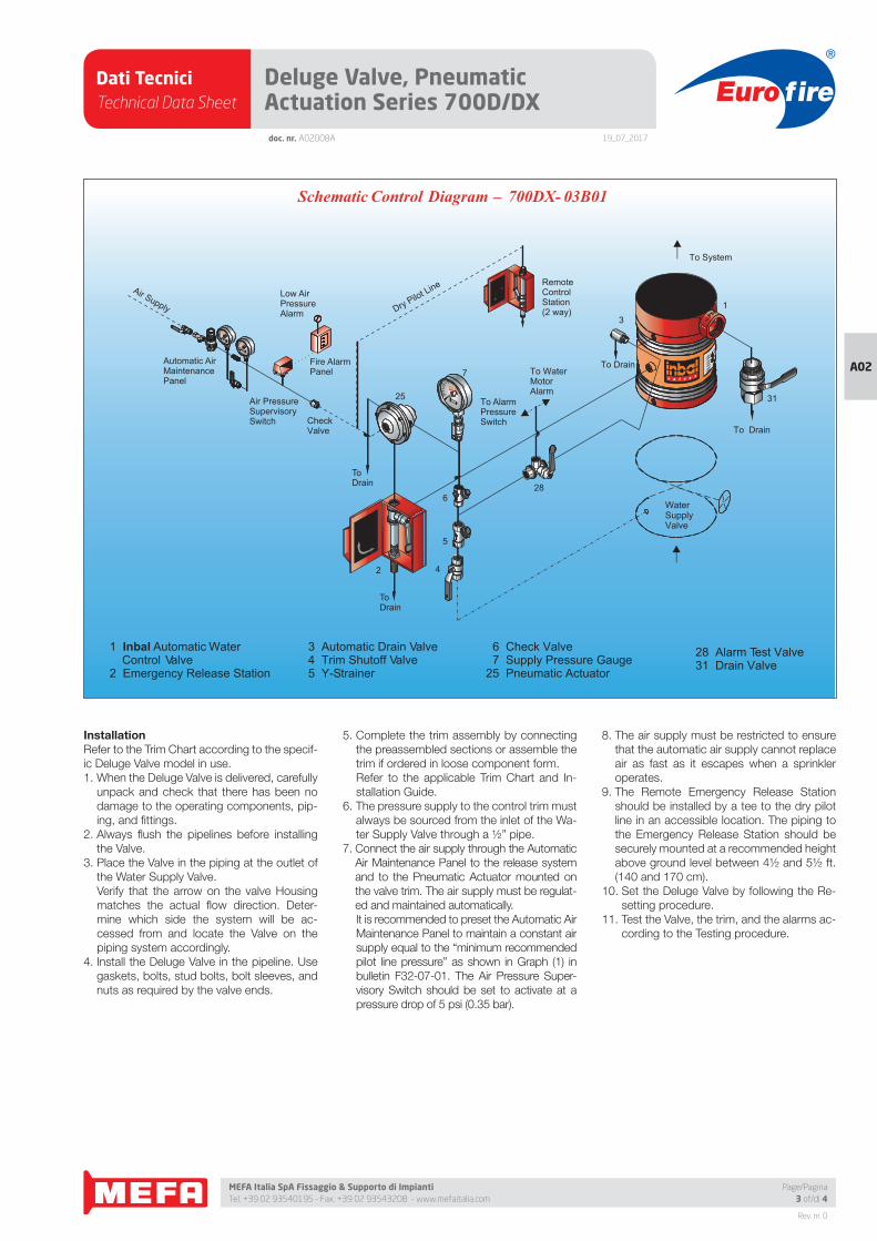
Dati TecniciTechnical Data Sheet
19_07_2017
Euro fire
MEFA Italia SpA Fissaggio & Supporto di Impianti Tel. +39 02 93540195 - Fax. +39 02 93543208 - www.mefaitalia.com
Rev. nr. 0
A02
Page/Pagina3 of/di 4
doc. nr. A02008A
Deluge Valve, Pneumatic Actuation Series 700D/DX
InstallationRefer to the Trim Chart according to the specif-
ic Deluge Valve model in use.
1. When the Deluge Valve is delivered, carefully
unpack and check that there has been no
damage to the operating components, pip-
ing, and fi ttings.
2. Always fl ush the pipelines before installing
the Valve.
3. Place the Valve in the piping at the outlet of
the Water Supply Valve.
Verify that the arrow on the valve Housing
matches the actual fl ow direction. Deter-
mine which side the system will be ac-
cessed from and locate the Valve on the
piping system accordingly.
4. Install the Deluge Valve in the pipeline. Use
gaskets, bolts, stud bolts, bolt sleeves, and
nuts as required by the valve ends.
5. Complete the trim assembly by connecting
the preassembled sections or assemble the
trim if ordered in loose component form.
Refer to the applicable Trim Chart and In-
stallation Guide.
6. The pressure supply to the control trim must
always be sourced from the inlet of the Wa-
ter Supply Valve through a ½” pipe.
7. Connect the air supply through the Automatic
Air Maintenance Panel to the release system
and to the Pneumatic Actuator mounted on
the valve trim. The air supply must be regulat-
ed and maintained automatically.
It is recommended to preset the Automatic Air
Maintenance Panel to maintain a constant air
supply equal to the “minimum recommended
pilot line pressure” as shown in Graph (1) in
bulletin F32-07-01. The Air Pressure Super-
visory Switch should be set to activate at a
pressure drop of 5 psi (0.35 bar).
8. The air supply must be restricted to ensure
that the automatic air supply cannot replace
air as fast as it escapes when a sprinkler
operates.
9. The Remote Emergency Release Station
should be installed by a tee to the dry pilot
line in an accessible location. The piping to
the Emergency Release Station should be
securely mounted at a recommended height
above ground level between 4½ and 5½ ft.
(140 and 170 cm).
10. Set the Deluge Valve by following the Re-
setting procedure.
11. Test the Valve, the trim, and the alarms ac-
cording to the Testing procedure.
3 Automatic Drain Valve4 Trim Shutoff Valve5 Y-Strainer
1 Inbal Automatic Water Control Valve
2 Emergency Release Station
WaterSupplyValve
Air Supply
To System
Automatic Air MaintenancePanel
Fire AlarmPanel
CheckValve
Low Air PressureAlarm
Air Pressure SupervisorySwitch
To Drain
ToDrain
To Drain
To AlarmPressureSwitch
To WaterMotorAlarm
ToDrain
Dry Pilot Line
_Schematic Control Diagram 700DX- 03B01
6 Check Valve7 Supply Pressure Gauge
25 Pneumatic Actuator
MANUAL VALVE
CLOSEOPEN
EMERGENCY
4
5
7
31
13
25
628
2
RemoteControlStation(2 way)
28 Alarm Test Valve31 Drain Valve
OPEN
CLOSEEMERGENCY
MANUAL VALVE
Dati TecniciTechnical Data Sheet
19_07_2017
Euro fire
MEFA Italia SpA Fissaggio & Supporto di Impianti Tel. +39 02 93540195 - Fax. +39 02 93543208 - www.mefaitalia.com
NOTA GENERALE:
L’attrezzatura presentata in questo bollettino deve essere installata in conformità agli ultimi standard pubblicati dalle Norme UNI EN 12845, National Fire Protection Association, Factory Mutual Research Corporation o altre organizzazioni simili e anche con le disposizioni dei codici governativi o delle ordinanze laddove applicabili.Con la presente pagina tecnica, MEFA Italia intende fornire pertinenti informazioni tecniche, aggiornandole periodicamente.MEFA Italia non si ritiene responsabile in caso di errori di stampa o informazioni inesatte in quanto le stesse possono variare senza preavviso.
The equipment presented in this bulletin is to be installed in accordance with the latest published Standards of the UNI EN 12845, National Fire Protection Association, Factory Mutual Research Corporation, or other similar organizations and also with the provisions of governmental codes or ordinances whenever applicable.With this technical page, MEFA Italia intends to provide relevant technical information, updating them periodically.MEFA Italia is not responsible for any inaccurate print or inaccurate information as these may vary without prior notice.
NOTA EUROFIRE:
Eurofi re è un marchio registrato da MEFA Italia per la presentazione di tutti i prodotti della linea Antincendio.I fornitori dei prodotti Eurofi re vengono rigorosamente selezionati nel rispetto della qualità e delle caratteristiche distintive descrittte in questo documento tecnico.I fornitori dei prodotti potrebbero variare senza preavviso, ma sempre nel rispetto delle caratteristiche qui descritte.
Eurofi re is a registered trademark of MEFA Italia for the presentation of all products of the Fire Protection Line.The suppliers of Eurofi re products are strictly selected in compliance with the quality and distinctive features described in this technical document.Product providers may vary without notice, but always respecting the features described herein.
Rev. nr. 0
A02
Page/Pagina4 of/di 4
Deluge Valve, Pneumatic Actuation Series 700D/DXdoc. nr. A02008A
ResettingThe Deluge valve system must be reset and
restored to service as soon as possible after
automatic, emergency, or manual actuation.
1. After operation, close the Remote Control
Valve. The Deluge Valve will close drip tight.
Verify that the Pressure Supervisory Switch,
Low Air Pressure Alarm, and water fl ow
alarms are reset. Verify that the supply pres-
sure has been restored to the normal level.
2. After a manual emergency operation - close
the Emergency Release Valve.
The Deluge Valve will close drip tight and
water fl ow alarms are reset. Verify that the
supply pressure has been restored to the
normal level.
In either one of the operations exercised, the
system piping should drained.
Maintenance, Inspection, & TestingIt is recommended that periodic inspections
and tests be conducted by qualifi ed person-
nel to ensure that the Deluge Valve and related
equipment are in good operating condition.
The inspection and testing activities should
be done according to NFPA Standards, the
guidelines and regulations of the authorities
having jurisdiction, and the following instruc-
tions. It is recommended that the Deluge Valve
be tested, operated, cleaned, and inspected
at least on a routine basis.
InspectionA weekly Inspection is recommended:
1. Verify that the Water Supply Valve is sealed
in a fully open position.
2. Verify that the required water and air pres-
sures are being applied to the Deluge Valve
inlet, the trim, and to the Pneumatic Actu-
ator.
3. Verify that the Trim Shutoff Valve, Alarm Test
Valve, Emergency Release Valve, Pressure
Gauge Valve, and Drain Valve (if in use) are
in set position.
4. The Supply and air Pressure Gauges should
be checked for accuracy.
5. Visually inspect for broken or missing parts,
or other evidence of impaired protection.
Strainer CleaningA quarterly Strainer Cleaning is recommended:
1. Close the Trim Shutoff Valve.
2. Remove the covers of the trim and alarm
Y-Strainers. Clean if necessary.
3. Open the Trim Shutoff Valve.
Alarm TestingA quarterly Alarm Testing is recommended:
Water Flow Alarm
1. Test the Water Motor Alarm or Alarm Pres-
sure Switch by opening the Alarm Test
Valve.
2. Water Motor Alarm should be audible.
Alarm Pressure Switch should activate. Ver-
ify that remote alarm signals are properly re-
ceived.
3. Close the Alarm Test Valve. All local alarms
stop sounding and pressure switch is reset.
All remote station alarms reset.
4. Verify that supply piping to alarm drains
properly.
Low Air Pressure Alarm
1. Close the Water Supply Valve.
2. Partially open the release valve on the pneu-
matic pilot system to reduce the pressure
to the predetermined alarm level (but not
below that level as this may inadvertently
activate Deluge Trim Testing).
3. Verify that the Low Air Pressure Alarm oper-
ates properly.
4. Close the inspector’s test valve. Verify that
normal pneumatic pressure is restored and
that the Low Air Pressure Alarm and Air
Pressure Supervisory Switch are reset.
5. Open the Water Supply Valve.
Deluge Trim TestingA semi-annual Deluge Trim Testing is recom-
mended. Testing of the control trim is conduct-
ed with no fl ow of water to the system.
1. Close the Water Supply Valve installed in the
inlet of the Deluge Valve.
2. Open the Remote Release Valve.
Verify that water is drained from the deluge
trim which simulates an open position of the
Deluge Valve. The Low Air Pressure Alarm
should operate.
3. Reset the valve by following the Resetting
procedure.
4. Open the Water Supply Valve.
Trip TestingAn annual Trip Testing is recommended.
Performing the Trip Testing will cause water to
fl ow from all open sprinklers and/or nozzles.
Prevent damage by taking the necessary pre-
cautions.
1. Trip the Deluge Valve to open by actuation
of either:
a) Remote Release valve
b) Emergency Release Valve.
All the water in the Valve Control Chamber is
allowed to vent to the atmosphere. The Del-
uge Valve will open and water will fl ow to the
system.
2. All the alarms should operate. Verify that the
whole system is working properly.
3. Reset the system by performing the instruc-
tions in Resetting.
4. Verify that water supply pressure and air
pressure have been restored to the normal
level.
RemovalTo remove the Deluge Valve:
1. Close all the pressure supply valves:
a) Water Supply Valve.
b) Trim Shutoff Valve.
c) Air supply valve.
2. Open the Emergency Release Valve to re-
lease the water pressure from the Valve
Control Chamber.
3. Open the Drain Valve to allow all the water
to drain.
4. Disconnect the union and remove the trim
from the valve.
5. Remove the Valve from the line for inspec-
tion.
6. To reinstall, follow the Installation procedure
section (use new gaskets for fl anged or wa-
fer valve).
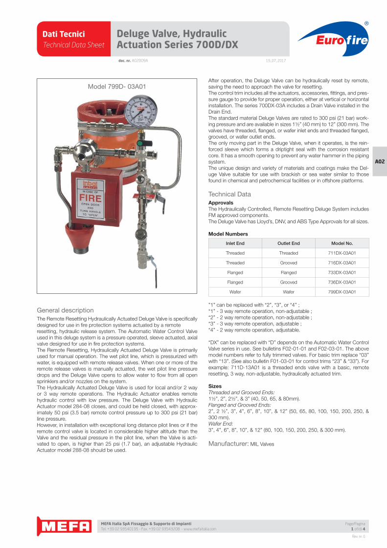
Dati TecniciTechnical Data Sheet
19_07_2017
Euro fire
MEFA Italia SpA Fissaggio & Supporto di Impianti Tel. +39 02 93540195 - Fax. +39 02 93543208 - www.mefaitalia.com
Rev. nr. 0
A02
Page/Pagina1 of/di 4
doc. nr. A02009A
Deluge Valve, Hydraulic Actuation Series 700D/DX
General description
The Remote Resetting Hydraulically Actuated Deluge Valve is specifi cally
designed for use in fi re protection systems actuated by a remote
resetting, hydraulic release system. The Automatic Water Control Valve
used in this deluge system is a pressure operated, sleeve actuated, axial
valve designed for use in fi re protection systems.
The Remote Resetting, Hydraulically Actuated Deluge Valve is primarily
used for manual operation. The wet pilot line, which is pressurized with
water, is equipped with remote release valves. When one or more of the
remote release valves is manually actuated, the wet pilot line pressure
drops and the Deluge Valve opens to allow water to fl ow from all open
sprinklers and/or nozzles on the system.
The Hydraulically Actuated Deluge Valve is used for local and/or 2 way
or 3 way remote operations. The Hydraulic Actuator enables remote
hydraulic control with low pressure. The Deluge Valve with Hydraulic
Actuator model 284-08 closes, and could be held closed, with approx-
imately 50 psi (3.5 bar) remote control pressure up to 300 psi (21 bar)
line pressure.
However, in installation with exceptional long distance pilot lines or if the
remote control valve is located in considerable higher altitude than the
Valve and the residual pressure in the pilot line, when the Valve is acti-
vated to open, is higher than 25 psi (1.7 bar), an adjustable Hydraulic
Actuator model 288-08 should be used.
After operation, the Deluge Valve can be hydraulically reset by remote,
saving the need to approach the valve for resetting.
The control trim includes all the actuators, accessories, fi ttings, and pres-
sure gauge to provide for proper operation, either at vertical or horizontal
installation. The series 700DX-03A includes a Drain Valve installed in the
Drain End.
The standard material Deluge Valves are rated to 300 psi (21 bar) work-
ing pressure and are available in sizes 1½” (40 mm) to 12” (300 mm). The
valves have threaded, fl anged, or wafer inlet ends and threaded fl anged,
grooved, or wafer outlet ends.
The only moving part in the Deluge Valve, when it operates, is the rein-
forced sleeve which forms a driptight seal with the corrosion resistant
core. It has a smooth opening to prevent any water hammer in the piping
system.
The unique design and variety of materials and coatings make the Del-
uge Valve suitable for use with brackish or sea water similar to those
found in chemical and petrochemical facilities or in offshore platforms.
Technical Data
ApprovalsThe Hydraulically Controlled, Remote Resetting Deluge System includes
FM approved components.
The Deluge Valve has Lloyd’s, DNV, and ABS Type Approvals for all sizes.
Model Numbers
Inlet End Outlet End Model No.
Threaded Threaded 711DX-03A01
Threaded Grooved 716DX-03A01
Flanged Flanged 733DX-03A01
Flanged Grooved 736DX-03A01
Wafer Wafer 799DX-03A01
”1” can be replaced with “2”, “3”, or “4” ;
“1” - 3 way remote operation, non-adjustable ;
“2” - 2 way remote operation, non-adjustable ;
“3” - 3 way remote operation, adjustable ;
“4” - 2 way remote operation, adjustable.
“DX” can be replaced with “D” depends on the Automatic Water Control
Valve series in use. See bulletins F02-01-01 and F02-03-01. The above
model numbers refer to fully trimmed valves. For basic trim replace “03”
with “13”. (See also bulletin F01-03-01 for control trims “23” & “33”). For
example: 711D-13A01 is a threaded ends valve with a basic, remote
resetting, 3 way, non-adjustable, hydraulically actuated trim.
SizesThreaded and Grooved Ends:
1½”, 2”, 2½”, & 3” (40, 50, 65, & 80mm).
Flanged and Grooved Ends:
2”, 2 ½”, 3”, 4”, 6”, 8”, 10”, & 12” (50, 65, 80, 100, 150, 200, 250, &
300 mm).
Wafer End:
3”, 4”, 6”, 8”, 10”, & 12” (80, 100, 150, 200, 250, & 300 mm).
Manufacturer: MIL Valves
Model 799D- 03A01
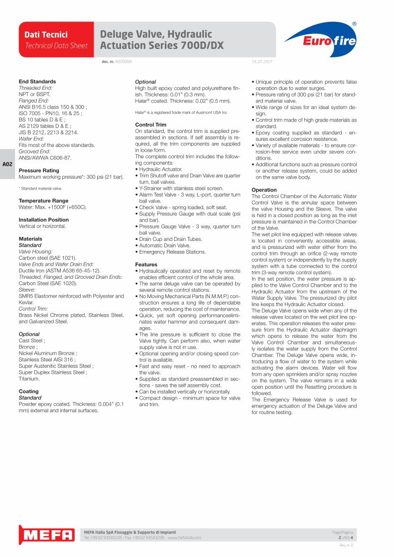
Dati TecniciTechnical Data Sheet
19_07_2017
Euro fire
MEFA Italia SpA Fissaggio & Supporto di Impianti Tel. +39 02 93540195 - Fax. +39 02 93543208 - www.mefaitalia.com
Rev. nr. 0
A02
doc. nr. A02009A
Deluge Valve, Hydraulic Actuation Series 700D/DX
Page/Pagina2 of/di 4
End StandardsThreaded End:
NPT or BSPT.
Flanged End:
ANSI B16.5 class 150 & 300 ;
ISO 7005 - PN10, 16 & 25 ;
BS 10 tables D & E ;
AS 2129 tables D & E ;
JIS B 2212, 2213 & 2214.
Wafer End:
Fits most of the above standards.
Grooved End:
ANSI/AWWA C606-87.
Pressure RatingMaximum working pressure*: 300 psi (21 bar).
* Standard material valve.
Temperature RangeWater: Max. +1500F (+650C).
Installation PositionVertical or horizontal.
MaterialsStandardValve Housing:
Carbon steel (SAE 1021).
Valve Ends and Wafer Drain End:
Ductile Iron (ASTM A536 65-45-12).
Threaded, Flanged, and Grooved Drain Ends:
Carbon Steel (SAE 1020).
Sleeve:
SMR5 Elastomer reinforced with Polyester and
Kevlar.
Control Trim:
Brass Nickel Chrome plated, Stainless Steel,
and Galvanized Steel.
OptionalCast Steel ;
Bronze ;
Nickel Aluminum Bronze ;
Stainless Steel AISI 316 ;
Super Austenitic Stainless Steel ;
Super Duplex Stainless Steel ;
Titanium.
CoatingStandardPowder epoxy coated. Thickness: 0.004” (0.1
mm) external and internal surfaces.
OptionalHigh built epoxy coated and polyurethane fi n-
ish. Thickness: 0.01” (0.3 mm).
Halar® coated. Thickness: 0.02” (0.5 mm).
Halar® is a registered trade mark of Ausimont USA Inc
Control TrimOn standard, the control trim is supplied pre-
assembled in sections. If self assembly is re-
quired, all the trim components are supplied
in loose form.
The complete control trim includes the follow-
ing components:
• Hydraulic Actuator.
• Trim Shutoff valve and Drain Valve are quarter
turn, ball valves.
• Y-Strainer with stainless steel screen.
• Alarm Test Valve - 3 way, L-port, quarter turn
ball valve.
• Check Valve - spring loaded, soft seat.
• Supply Pressure Gauge with dual scale (psi
and bar).
• Pressure Gauge Valve - 3 way, quarter turn
ball valve.
• Drain Cup and Drain Tubes.
• Automatic Drain Valve.
• Emergency Release Stations.
Features• Hydraulically operated and reset by remote
enables effi cient control of the whole area.
• The same deluge valve can be operated by
several remote control stations.
• No Moving Mechanical Parts (N.M.M.P.) con-
struction ensures a long life of dependable
operation, reducing the cost of maintenance.
• Quick, yet soft opening performanceelimi-
nates water hammer and consequent dam-
ages.
• The line pressure is suffi cient to close the
Valve tightly. Can perform also, when water
supply valve is not in use.
• Optional opening and/or closing speed con-
trol is available.
• Fast and easy reset - no need to approach
the valve.
• Supplied as standard preassembled in sec-
tions - saves the self assembly cost.
• Can be installed vertically or horizontally.
• Compact design - minimum space for valve
and trim.
• Unique principle of operation prevents false
operation due to water surges.
• Pressure rating of 300 psi (21 bar) for stand-
ard material valve.
• Wide range of sizes for an ideal system de-
sign.
• Control trim made of high grade materials as
standard.
• Epoxy coating supplied as standard - en-
sures excellent corrosion resistence.
• Variety of available materials - to ensure cor-
rosion-free service even under severe con-
ditions.
• Additional functions such as pressure control
or another release system, could be added
on the same valve body.
OperationThe Control Chamber of the Automatic Water
Control Valve is the annular space between
the valve Housing and the Sleeve. The valve
is held in a closed position as long as the inlet
pressure is maintained in the Control Chamber
of the Valve.
The wet pilot line equipped with release valves
is located in conveniently accessible areas,
and is pressurized with water either from the
control trim through an orifi ce (2-way remote
control system) or independently by the supply
system with a tube connected to the control
trim (3-way remote control system).
In the set position, the water pressure is ap-
plied to the Valve Control Chamber and to the
Hydraulic Actuator from the upstream of the
Water Supply Valve. The pressurized dry pilot
line keeps the Hydraulic Actuator closed.
The Deluge Valve opens wide when any of the
release valves located on the wet pilot line op-
erates. This operation releases the water pres-
sure from the Hydraulic Actuator diaphragm
which opens to release the water from the
Valve Control Chamber and simultaneous-
ly isolates the water supply from the Control
Chamber. The Deluge Valve opens wide, in-
troducing a fl ow of water to the system while
activating the alarm devices. Water will fl ow
from any open sprinklers and/or spray nozzles
on the system. The valve remains in a wide
open position until the Resetting procedure is
followed.
The Emergency Release Valve is used for
emergency actuation of the Deluge Valve and
for routine testing.
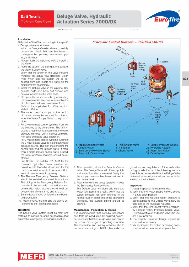
Dati TecniciTechnical Data Sheet
19_07_2017
Euro fire
MEFA Italia SpA Fissaggio & Supporto di Impianti Tel. +39 02 93540195 - Fax. +39 02 93543208 - www.mefaitalia.com
Rev. nr. 0
A02
Page/Pagina3 of/di 4
doc. nr. A02009A
Deluge Valve, Hydraulic Actuation Series 700D/DX
InstallationRefer to the Trim Chart according to the specif-
ic Deluge Valve model in use.
1. When the Deluge Valve is delivered, carefully
unpack and check that there has been no
damage to the operating components, pip-
ing, and fi ttings.
2. Always fl ush the pipelines before installing
the Valve.
3. Place the Valve in the piping at the outlet of
the Water Supply Valve.
Verify that the arrow on the valve Housing
matches the actual fl ow direction. Deter-
mine which side the system will be ac-
cessed from and locate the Valve on the
piping system accordingly.
4. Install the Deluge Valve in the pipeline. Use
gaskets, bolts, stud bolts, bolt sleeves, and
nuts as required by the valve ends.
5. Complete the trim assembly by connecting
the preassembled sections, or assemble the
trim if ordered in loose component form.
Refer to the applicable Trim Chart and In-
stallation Guide.
6. The water pressure supply to the control
trim must always be sourced from the in-
let of the Water Supply Valve through a ½”
pipe.
7. For 2-way remote control systems: Connect
the pilot line to the control trim. The trim in-
cludes a restriction to ensure that the water
pressure in the wet pilot line drops suffi cient-
ly in case of release valve operation.
For 3-way remote control systems: Connect
the 3-way release valve to a constant water
pressure source. The pilot line connects the
control trim and the release valve. If more
than a single remote control valve is used,
the water pressure source(s) should be re-
stricted.
See Graph (1) in bulletin F32-06-01 for the
minimum hydraulic control pressure re-
quired to hold the Valve closed and for the
maximum residual control pressure still al-
lowed to ensure smooth opening.
8. The Remote Emergency Release Stations
should be installed in accessible locations.
The piping to the Emergency Release Sta-
tion should be securely mounted at a rec-
ommended height above ground level be-
tween 4½ and 5½ ft. (140 and 170 cm.).
9. Set the Deluge Valve by following the Reset-
ting procedure.
10. Test the Valve, the trim, and the alarms ac-
cording to the Testing procedure.
ResettingThe Deluge valve system must be reset and
restored to service as soon as possible after
automatic, emergency, or manual actuation.
1. After operation, close the Remote Control
Valve. The Deluge Valve will close drip tight
and water fl ow alarms are reset. Verify that
the supply pressure has been restored to
the normal level.
2. After a manual emergency operation - close
the Emergency Release Valve.
The Deluge Valve will close drip tight and
water fl ow alarms are reset. Verify that the
supply pressure has been restored to the
normal level. In either one of the operations
exercised, the system piping should be
drained.
Maintenance, Inspection, & TestingIt is recommended that periodic inspections
and tests be conducted by qualifi ed person-
nel to ensure that the Deluge Valve and related
equipment are in good operating condition.
The inspection and testing activities should
be done according to NFPA Standards, the
guidelines and regulations of the authorities
having jurisdiction, and the following instruc-
tions. It is recommended that the Deluge Valve
be tested, operated, cleaned, and inspected at
least on a routine basis.
InspectionA weekly Inspection is recommended:
1. Verify that the Water Supply Valve is sealed
in a fully open position.
2. Verify that the required water pressure is
being applied to the Deluge Valve inlet, the
trim, and to the Hydraulic Actuator.
3. Verify that the Trim Shutoff Valve, Emergen-
cy Release Valve, Pressure Gauge Valve,
Hydraulic Actuator, and Drain Valve (if in use)
are in set position.
4. The Supply Pressure Gauge should be
checked for accuracy.
5. Visually inspect for broken or missing parts,
or other evidence of impaired protection.
4 Trim Shutoff Valve5 Y-Strainer6 Check Valve
1 Inbal Automatic Water Control Valve
2 Emergency Release Station3 Automatic Drain Valve
_Schematic Control Diagram 700DX-03A01/03
7 Supply Pressure Gauge25 Hydraulic Actuator28 Alarm Test Valve31 Drain Valve
MANUAL VALVE
CLOSEOPEN
EMERGENCY
MANUAL VALVE
CLOSEOPEN
EMERGENCY
50
100
300
0
ToDrain
To AlarmPressureSwitch
To WaterMotorAlarm
ToDrain
ToDrain
WaterSupplyValve
ToDrain
To Drain
Wet Pilot Line
2 4
25
5
6
7
28
31
3
1
To SystemRemoteReleaseStation(3-way)
AlternativeWater Supply
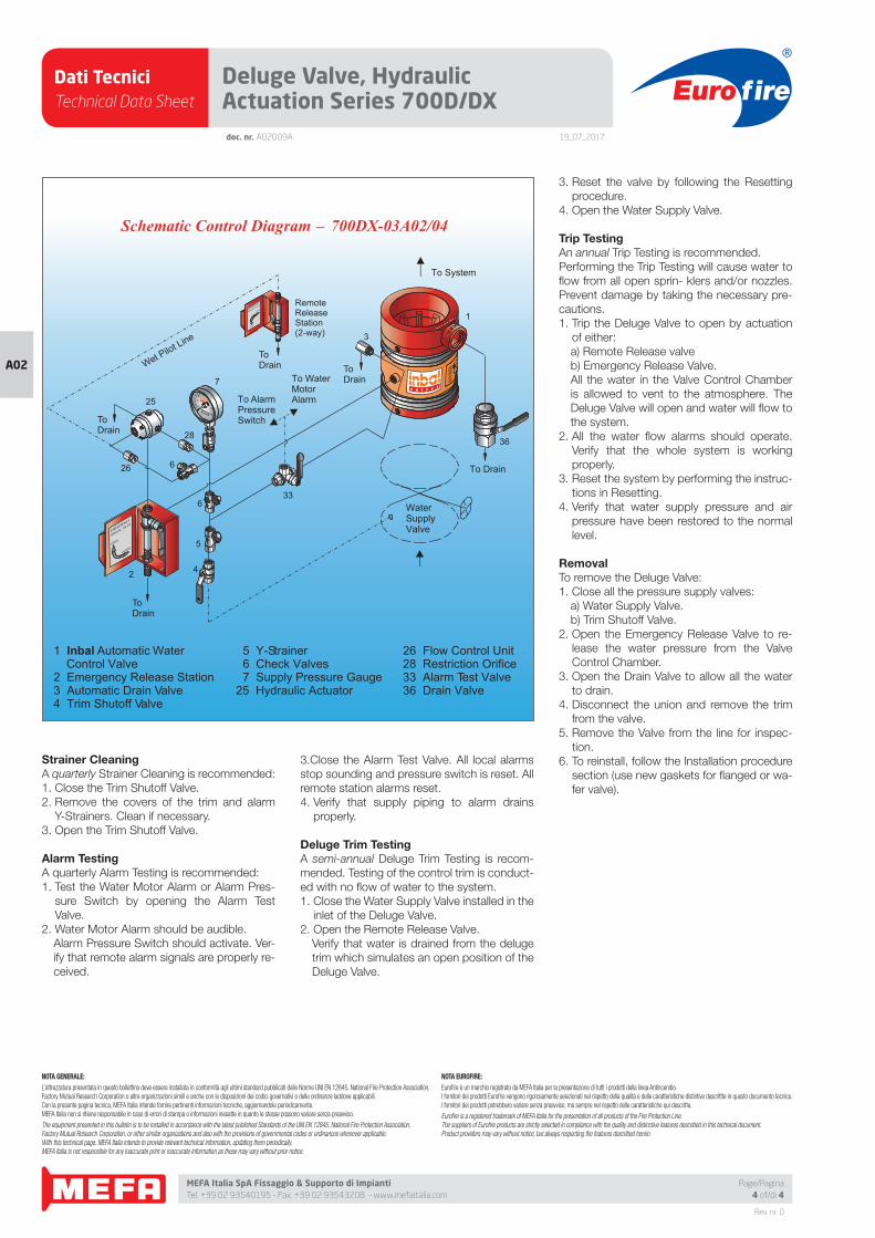
Dati TecniciTechnical Data Sheet
19_07_2017
Euro fire
MEFA Italia SpA Fissaggio & Supporto di Impianti Tel. +39 02 93540195 - Fax. +39 02 93543208 - www.mefaitalia.com
NOTA GENERALE:
L’attrezzatura presentata in questo bollettino deve essere installata in conformità agli ultimi standard pubblicati dalle Norme UNI EN 12845, National Fire Protection Association, Factory Mutual Research Corporation o altre organizzazioni simili e anche con le disposizioni dei codici governativi o delle ordinanze laddove applicabili.Con la presente pagina tecnica, MEFA Italia intende fornire pertinenti informazioni tecniche, aggiornandole periodicamente.MEFA Italia non si ritiene responsabile in caso di errori di stampa o informazioni inesatte in quanto le stesse possono variare senza preavviso.
The equipment presented in this bulletin is to be installed in accordance with the latest published Standards of the UNI EN 12845, National Fire Protection Association, Factory Mutual Research Corporation, or other similar organizations and also with the provisions of governmental codes or ordinances whenever applicable.With this technical page, MEFA Italia intends to provide relevant technical information, updating them periodically.MEFA Italia is not responsible for any inaccurate print or inaccurate information as these may vary without prior notice.
NOTA EUROFIRE:
Eurofi re è un marchio registrato da MEFA Italia per la presentazione di tutti i prodotti della linea Antincendio.I fornitori dei prodotti Eurofi re vengono rigorosamente selezionati nel rispetto della qualità e delle caratteristiche distintive descrittte in questo documento tecnico.I fornitori dei prodotti potrebbero variare senza preavviso, ma sempre nel rispetto delle caratteristiche qui descritte.
Eurofi re is a registered trademark of MEFA Italia for the presentation of all products of the Fire Protection Line.The suppliers of Eurofi re products are strictly selected in compliance with the quality and distinctive features described in this technical document.Product providers may vary without notice, but always respecting the features described herein.
Rev. nr. 0
A02
Page/Pagina4 of/di 4
Deluge Valve, Hydraulic Actuation Series 700D/DXdoc. nr. A02009A
Strainer CleaningA quarterly Strainer Cleaning is recommended:
1. Close the Trim Shutoff Valve.
2. Remove the covers of the trim and alarm
Y-Strainers. Clean if necessary.
3. Open the Trim Shutoff Valve.
Alarm TestingA quarterly Alarm Testing is recommended:
1. Test the Water Motor Alarm or Alarm Pres-
sure Switch by opening the Alarm Test
Valve.
2. Water Motor Alarm should be audible.
Alarm Pressure Switch should activate. Ver-
ify that remote alarm signals are properly re-
ceived.
3.Close the Alarm Test Valve. All local alarms
stop sounding and pressure switch is reset. All
remote station alarms reset.
4. Verify that supply piping to alarm drains
properly.
Deluge Trim TestingA semi-annual Deluge Trim Testing is recom-
mended. Testing of the control trim is conduct-
ed with no fl ow of water to the system.
1. Close the Water Supply Valve installed in the
inlet of the Deluge Valve.
2. Open the Remote Release Valve.
Verify that water is drained from the deluge
trim which simulates an open position of the
Deluge Valve.
3. Reset the valve by following the Resetting
procedure.
4. Open the Water Supply Valve.
Trip TestingAn annual Trip Testing is recommended.
Performing the Trip Testing will cause water to
fl ow from all open sprin- klers and/or nozzles.
Prevent damage by taking the necessary pre-
cautions.
1. Trip the Deluge Valve to open by actuation
of either:
a) Remote Release valve
b) Emergency Release Valve.
All the water in the Valve Control Chamber
is allowed to vent to the atmosphere. The
Deluge Valve will open and water will fl ow to
the system.
2. All the water fl ow alarms should operate.
Verify that the whole system is working
properly.
3. Reset the system by performing the instruc-
tions in Resetting.
4. Verify that water supply pressure and air
pressure have been restored to the normal
level.
RemovalTo remove the Deluge Valve:
1. Close all the pressure supply valves:
a) Water Supply Valve.
b) Trim Shutoff Valve.
2. Open the Emergency Release Valve to re-
lease the water pressure from the Valve
Control Chamber.
3. Open the Drain Valve to allow all the water
to drain.
4. Disconnect the union and remove the trim
from the valve.
5. Remove the Valve from the line for inspec-
tion.
6. To reinstall, follow the Installation procedure
section (use new gaskets for fl anged or wa-
fer valve).
OPEN
CLOSEEMERGENCY
MANUAL VALVE
5 Y-Strainer6 Check Valves7 Supply Pressure Gauge
25 Hydraulic Actuator
26 Flow Control Unit28 Restriction Orifice33 Alarm Test Valve36 Drain Valve
_Schematic Control Diagram 700DX-03A02/04
ToDrain
To AlarmPressureSwitch
To WaterMotorAlarm
ToDrain
ToDrain
WaterSupplyValve
ToDrain
To Drain
Wet Pilot Line
RemoteReleaseStation(2-way)
2 4
28
26
25
5
6
6
33
7
36
3
1
To System
MANUAL VALVE
CLOSEOPEN
EMERGENCY
50
100
300
0
1 Inbal Automatic Water Control Valve
2 Emergency Release Station3 Automatic Drain Valve4 Trim Shutoff Valve
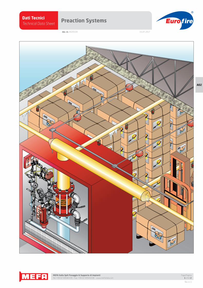
Dati TecniciTechnical Data Sheet
19_07_2017
Euro fire
MEFA Italia SpA Fissaggio & Supporto di Impianti Tel. +39 02 93540195 - Fax. +39 02 93543208 - www.mefaitalia.com
Rev. nr. 0
A02
Page/Pagina1 of/di 2
doc. nr. A02010A
Preaction Systems
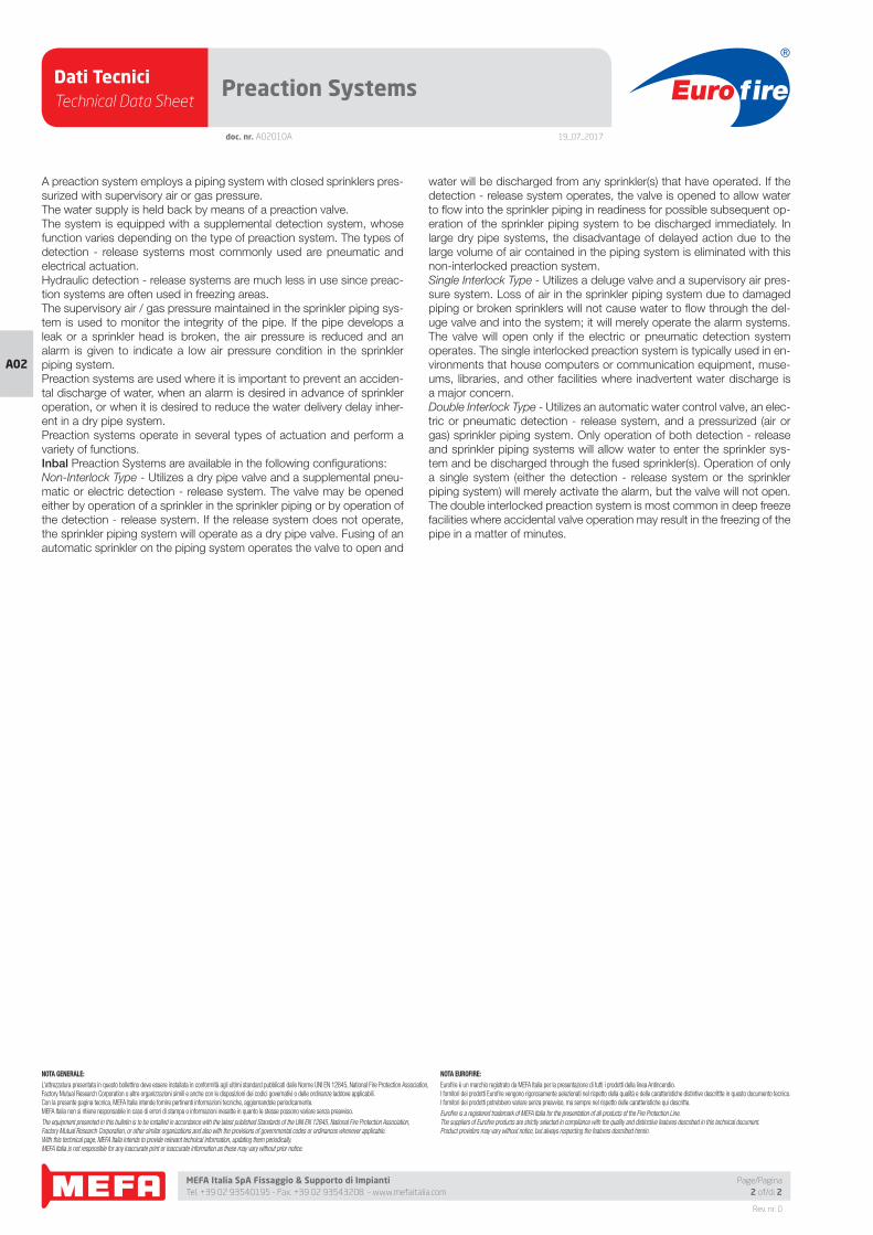
Dati TecniciTechnical Data Sheet
19_07_2017
Euro fire
MEFA Italia SpA Fissaggio & Supporto di Impianti Tel. +39 02 93540195 - Fax. +39 02 93543208 - www.mefaitalia.com
NOTA GENERALE:
L’attrezzatura presentata in questo bollettino deve essere installata in conformità agli ultimi standard pubblicati dalle Norme UNI EN 12845, National Fire Protection Association, Factory Mutual Research Corporation o altre organizzazioni simili e anche con le disposizioni dei codici governativi o delle ordinanze laddove applicabili.Con la presente pagina tecnica, MEFA Italia intende fornire pertinenti informazioni tecniche, aggiornandole periodicamente.MEFA Italia non si ritiene responsabile in caso di errori di stampa o informazioni inesatte in quanto le stesse possono variare senza preavviso.
The equipment presented in this bulletin is to be installed in accordance with the latest published Standards of the UNI EN 12845, National Fire Protection Association, Factory Mutual Research Corporation, or other similar organizations and also with the provisions of governmental codes or ordinances whenever applicable.With this technical page, MEFA Italia intends to provide relevant technical information, updating them periodically.MEFA Italia is not responsible for any inaccurate print or inaccurate information as these may vary without prior notice.
NOTA EUROFIRE:
Eurofi re è un marchio registrato da MEFA Italia per la presentazione di tutti i prodotti della linea Antincendio.I fornitori dei prodotti Eurofi re vengono rigorosamente selezionati nel rispetto della qualità e delle caratteristiche distintive descrittte in questo documento tecnico.I fornitori dei prodotti potrebbero variare senza preavviso, ma sempre nel rispetto delle caratteristiche qui descritte.
Eurofi re is a registered trademark of MEFA Italia for the presentation of all products of the Fire Protection Line.The suppliers of Eurofi re products are strictly selected in compliance with the quality and distinctive features described in this technical document.Product providers may vary without notice, but always respecting the features described herein.
Rev. nr. 0
A02
Page/Pagina2 of/di 2
Preaction Systems
doc. nr. A02010A
A preaction system employs a piping system with closed sprinklers pres-
surized with supervisory air or gas pressure.
The water supply is held back by means of a preaction valve.
The system is equipped with a supplemental detection system, whose
function varies depending on the type of preaction system. The types of
detection - release systems most commonly used are pneumatic and
electrical actuation.
Hydraulic detection - release systems are much less in use since preac-
tion systems are often used in freezing areas.
The supervisory air / gas pressure maintained in the sprinkler piping sys-
tem is used to monitor the integrity of the pipe. If the pipe develops a
leak or a sprinkler head is broken, the air pressure is reduced and an
alarm is given to indicate a low air pressure condition in the sprinkler
piping system.
Preaction systems are used where it is important to prevent an acciden-
tal discharge of water, when an alarm is desired in advance of sprinkler
operation, or when it is desired to reduce the water delivery delay inher-
ent in a dry pipe system.
Preaction systems operate in several types of actuation and perform a
variety of functions.
Inbal Preaction Systems are available in the following confi gurations:
Non-Interlock Type - Utilizes a dry pipe valve and a supplemental pneu-
matic or electric detection - release system. The valve may be opened
either by operation of a sprinkler in the sprinkler piping or by operation of
the detection - release system. If the release system does not operate,
the sprinkler piping system will operate as a dry pipe valve. Fusing of an
automatic sprinkler on the piping system operates the valve to open and
water will be discharged from any sprinkler(s) that have operated. If the
detection - release system operates, the valve is opened to allow water
to fl ow into the sprinkler piping in readiness for possible subsequent op-
eration of the sprinkler piping system to be discharged immediately. In
large dry pipe systems, the disadvantage of delayed action due to the
large volume of air contained in the piping system is eliminated with this
non-interlocked preaction system.
Single Interlock Type - Utilizes a deluge valve and a supervisory air pres-
sure system. Loss of air in the sprinkler piping system due to damaged
piping or broken sprinklers will not cause water to fl ow through the del-
uge valve and into the system; it will merely operate the alarm systems.
The valve will open only if the electric or pneumatic detection system
operates. The single interlocked preaction system is typically used in en-
vironments that house computers or communication equipment, muse-
ums, libraries, and other facilities where inadvertent water discharge is
a major concern.
Double Interlock Type - Utilizes an automatic water control valve, an elec-
tric or pneumatic detection - release system, and a pressurized (air or
gas) sprinkler piping system. Only operation of both detection - release
and sprinkler piping systems will allow water to enter the sprinkler sys-
tem and be discharged through the fused sprinkler(s). Operation of only
a single system (either the detection - release system or the sprinkler
piping system) will merely activate the alarm, but the valve will not open.
The double interlocked preaction system is most common in deep freeze
facilities where accidental valve operation may result in the freezing of the
pipe in a matter of minutes.
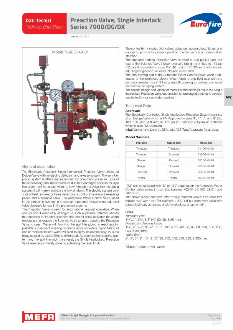
Dati TecniciTechnical Data Sheet
19_07_2017
Euro fire
MEFA Italia SpA Fissaggio & Supporto di Impianti Tel. +39 02 93540195 - Fax. +39 02 93543208 - www.mefaitalia.com
Rev. nr. 0
A02
Page/Pagina1 of/di 4
doc. nr. A02011A
Preaction Valve, Single Interlock Series 700D/DG/DX
General description
The Electrically Actuated, Single Interlocked, Preaction Valve utilizes an
Deluge Valve with an electric detection and release system. The sprinkler
piping system is effectively supervised by pneumatic pressure. Loss of
the supervising pneumatic pressure due to a damaged sprinkler or pipe
line system will not cause water to fl ow through the Valve into the piping
system; it will merely activate the low air alarm. The electric system con-
sists of heat, smoke, or fl ame detectors, a control ( fi re alarm & releasing)
panel, and a solenoid valve. The Automatic Water Control Valve, used
in this preaction system, is a pressure operated, sleeve actuated, axial
valve designed for use in fi re protection systems.
The Preaction Valve is used for automatic or manual operation. When
one (or two-if electrically arranged in such a pattern) detector senses
the presence of fi re and operates, the control panel activates the alarm
devices and energizes the Solenoid Valve to open, causing the Preaction
Valve to open. Water will fl ow into the sprinkler piping in readiness for
possible subsequent opening of one or more sprinklers. Upon fusing of
one or more sprinklers, water will start to spray instantaneously, thus the
delay caused by a pipe fi lling is eliminated. As soon as the releasing sys-
tem and the sprinkler piping are reset, the Single Interlocked, Preaction
Valve resetting is merely done by activating the reset knob.
The control trim includes pilot valves, actuators, accessories, fi ttings, and
gauges to provide for proper operation in either vertical or horizontal in-
stallation.
The standard material Preaction Valve is rated to 300 psi (21 bar), but
due to the Solenoid Valve’s lower pressure rating it is limited to 175 psi
(12 bar). It is available in sizes 1½” (40 mm) to 12” (300 mm) with thread-
ed, fl anged, grooved, or wafer inlet and outlet ends.
The only moving part in the Automatic Water Control Valve, when it op-
erates, is the reinforced sleeve which forms a drip-tight seal with the
corrosion resistant core. It has a smooth opening to prevent any water
hammer in the piping system.
The unique design and variety of materials and coatings make the Single
Interlocked Preaction Valve dependable for prolonged periods of service,
unaffected by various water qualities.
Technical Data
ApprovalsThe Electrically Controlled Single Interlocked Preaction System consists
of an Deluge Valve which is FM Approved in sizes 3”, 4”, 6”, and 8” (80,
100, 150, and 200 mm) to 175 psi (12 bar) and a hydraulic Actuator
which is also FM Approved.
Inbal Valves have Lloyd’s , DNV, and ABS Type Approvals for all sizes.
Model Numbers
Inlet End Outlet End Model No.
Threaded Threaded 711DG-04I01
Threaded Grooved 716DG-04I01
Flanged Flanged 733DG-04I01
Flanged Grooved 736DG-04I01
Grooved Grooved 766DG-04I01
Wafer Wafer 799DG-04I01
“DG” can be replaced with “D” or “DX” depends on the Automatic Water
Control Valve series in use. See bulletins F02-01-01, F02-02-01, and
F02-03-01.
The above model numbers refer to fully trimmed valves. For basic trim
replace “04” with “14”. For example: 799D-14I is a wafer type valve with
basic electrically actuated, single interlocked, preaction trim.
SizesThreaded End:
1½”, 2”, 2½”, & 3” (40, 50, 65, & 80 mm).
Flanged and Grooved Ends:
1½”, 2”, 2½”, 3”, 4”, 6”, 8”, 10”, & 12” (40, 50, 65, 80, 100, 150, 200,
250, & 300 mm).
Wafer End:
3”, 4”, 6”, 8”, 10”, & 12” (80, 100, 150, 200, 250, & 300 mm).
Manufacturer: MIL Valves
Series 700D/DG/DX - 04/14 I01 Electric AcModel 799DG- 04I01
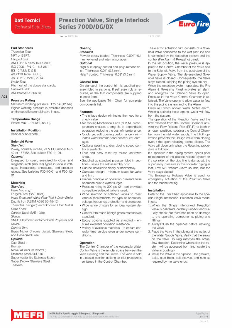
Dati TecniciTechnical Data Sheet
19_07_2017
Euro fire
MEFA Italia SpA Fissaggio & Supporto di Impianti Tel. +39 02 93540195 - Fax. +39 02 93543208 - www.mefaitalia.com
Rev. nr. 0
A02
doc. nr. A02011A
Preaction Valve, Single Interlock Series 700D/DG/DX
Page/Pagina2 of/di 4
End StandardsThreaded End:
NPT or BSPT.
Flanged End:
ANSI B16.5 class 150 & 300 ;
ISO 7005 - PN10, 16 & 25 ;
BS 10 Table D & E ;
AS 2129 Table D & E ;
Jis B 2212, 2213, 2214.
Wafer End:
Fits most of the above standards.
Grooved End:
ANSI/AWWA C606-87.
Pressure RatingMaximum working pressure: 175 psi (12 bar).
Higher working pressure is available depends
on the specifi c solenoid valve in use.
Temperature RangeWater: Max. +1500F (+650C).
Installation PositionVertical or horizontal.
Solenoid ValveStandard2-way, normally closed, 24 V DC, model 157-
42 or 157-52. See bulletin F30-11-01.
OptionalEnergized to open, energized to close, and
magnetic latch (impulse) types in various volt-
ages, frequencies, enclosures, and pressure
ratings. See bulletins F30-10-01 and F30-12-
01.
MaterialsStandardValve Housing:
Forged Steel (SAE 1021).
Valve Ends and Wafer Flow Test & Drain Ends:
Ductile Iron (ASTM A536 65-45-12).
Threaded, Flanged, and Grooved Flow Test &
Drain Ends:
Carbon Steel (SAE 1020).
Sleeve:
SMR5 Elastomer reinforced with Polyester and
Kevlar.
Control Trim:
Brass Nickel Chrome plated, Stainless Steel,
and Galvanized Steel.
OptionalCast Steel ;
Bronze ;
Nickel Aluminium Bronze ;
Stainless Steel AISI 316 ;
Super Austenitic Stainless Steel ;
Super Duplex Stainless Steel ;
Titanium.
CoatingStandardPowder epoxy coated. Thickness: 0.004” (0.1
mm ) external and internal surfaces.
OptionalHigh built epoxy coated and polyurethane fi n-
ish. Thickness: 0.01” (0.3 mm).
Halar® coated. Thickness: 0.02” (0.5 mm)
Control TrimOn standard, the control trim is supplied pre-
assembled in sections. If self assembly is re-
quired, all the trim components are supplied
in loose form.
See the applicable Trim Chart for complete
components list.
Features• The unique design eliminates the need for a
check valve
• No Moving Mechanical Parts (N.M.M.P.) con-
struction ensures a long life of dependable
operation, reducing the cost of maintenance.
• Quick, yet soft opening performance - elim-
inates water hammer and consequent dam-
ages.
• Optional opening and/or closing speed con-
trol is available.
• Fast and easy reset by thumb activated
knob.
• Supplied as standard preassembled in sec-
tions - saves the self assembly cost.
• Can be installed vertically or horizontally.
• Compact design - minimum space for valve
and trim.
• Unique principle of operation prevents false
operation due to water surges.
• Pressure rating to 300 psi (21 bar) provided
compatible solenoid valve is used.
• Wide selection of solenoid valves to meet
various requirements for type of operation,
voltage, frequency, protection and enclosure.
• Wide range of sizes for an ideal system de-
sign.
• Control trim made of high grade materials as
standard.
• Epoxy coating supplied as standard - en-
sures excellent corrosion resistence.
• Variety of available materials - to ensure cor-
rosion-free service even under severe con-
ditions.
OperationThe Control Chamber of the Automatic Water
Control Valve is the annular space between the
valve Housing and the Sleeve. The valve is held
in a closed position as long as inlet pressure is
maintained in the Control Chamber.
The electric actuation trim consists of a Sole-
noid Valve connected to the wet pilot line and
is controlled by the detection system and the
control (Fire Alarm & Releasing) panel.
In the set position, the water pressure is ap-
plied to the Control Chamber of the Valve and
to the Solenoid Valve from the upstream of the
Water Supply Valve. The de-energized Sole-
noid Valve is closed. Consequently, the Valve
stays closed, keeping the piping system dry.
When the detection system operates, the Fire
Alarm & Releasing Panel activates an alarm
and energizes the Solenoid Valve to open.
Pressure in the Valve Control Chamber is re-
leased. The Valve opens to allow water to fl ow
into the piping system and to the Alarm
Pressure Switch and/or Water Motor Alarm.
When a sprinkler head opens, water will fl ow
from the system.
The operation of the Preaction Valve and the
fl ow released from the Control Chamber acti-
vate the Flow Release Pilot (F.R.P.) to latch in
an open position, isolating the Control Cham-
ber from the inlet water supply. The F.R.P. op-
eration prevents the Deluge Valve from closing
even if the open releasing device closes. The
Valve will close only when the Resetting proce-
dure is followed.
If a sprinkler in the piping system opens prior
to operation of the electric release system or
if a sprinkler on the pipe line is damaged, the
supervisory pressure in the sprinkler piping is
lost, Low Air Pressure Alarm sounds, but the
Valve stays closed.
The Emergency Release Valve is used for
emergency actuation of the Preaction Valve
and for routine testing.
InstallationRefer to the Trim Chart applicable to the spe-
cifi c Single Interlocked, Preaction Valve model
in use.
1. When the Single Interlocked Preaction
Valve is delivered, carefully unpack and vis-
ually check that there has been no damage
to the operating components, piping and
fi ttings.
2. Always fl ush the pipelines before installing
the Valve.
3. Place the Valve in the piping at the outlet of
the Water Supply Valve. Verify that the arrow
on the valve Housing matches the actual
fl ow direction. Determine which side the sy-
stem will be accessed from and locate the
Valve accordingly.
4. Install the Valve in the pipeline. Use gaskets,
bolts, stud bolts, bolt sleeves, and nuts as
required by the valve ends.
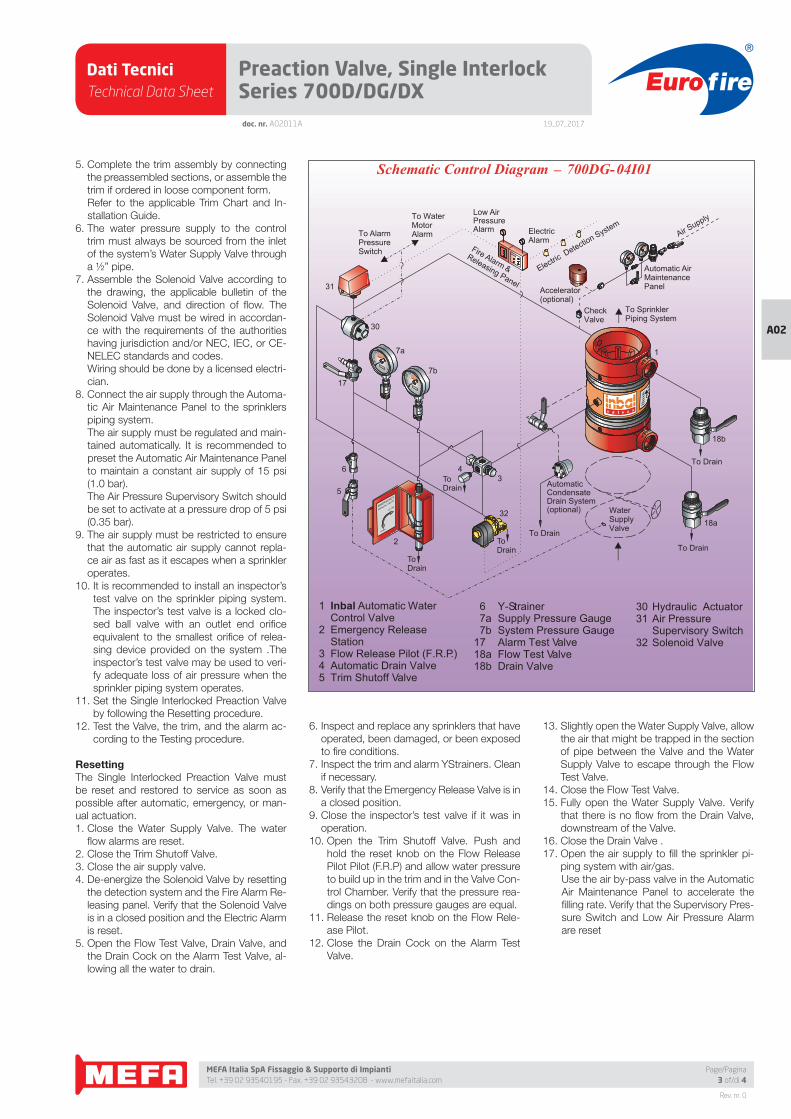
Dati TecniciTechnical Data Sheet
19_07_2017
Euro fire
MEFA Italia SpA Fissaggio & Supporto di Impianti Tel. +39 02 93540195 - Fax. +39 02 93543208 - www.mefaitalia.com
Rev. nr. 0
A02
Page/Pagina3 of/di 4
doc. nr. A02011A
Preaction Valve, Single Interlock Series 700D/DG/DX
5. Complete the trim assembly by connecting
the preassembled sections, or assemble the
trim if ordered in loose component form.
Refer to the applicable Trim Chart and In-
stallation Guide.
6. The water pressure supply to the control
trim must always be sourced from the inlet
of the system’s Water Supply Valve through
a ½” pipe.
7. Assemble the Solenoid Valve according to
the drawing, the applicable bulletin of the
Solenoid Valve, and direction of fl ow. The
Solenoid Valve must be wired in accordan-
ce with the requirements of the authorities
having jurisdiction and/or NEC, IEC, or CE-
NELEC standards and codes.
Wiring should be done by a licensed electri-
cian.
8. Connect the air supply through the Automa-
tic Air Maintenance Panel to the sprinklers
piping system.
The air supply must be regulated and main-
tained automatically. It is recommended to
preset the Automatic Air Maintenance Panel
to maintain a constant air supply of 15 psi
(1.0 bar).
The Air Pressure Supervisory Switch should
be set to activate at a pressure drop of 5 psi
(0.35 bar).
9. The air supply must be restricted to ensure
that the automatic air supply cannot repla-
ce air as fast as it escapes when a sprinkler
operates.
10. It is recommended to install an inspector’s
test valve on the sprinkler piping system.
The inspector’s test valve is a locked clo-
sed ball valve with an outlet end orifi ce
equivalent to the smallest orifi ce of relea-
sing device provided on the system .The
inspector’s test valve may be used to veri-
fy adequate loss of air pressure when the
sprinkler piping system operates.
11. Set the Single Interlocked Preaction Valve
by following the Resetting procedure.
12. Test the Valve, the trim, and the alarm ac-
cording to the Testing procedure.
ResettingThe Single Interlocked Preaction Valve must
be reset and restored to service as soon as
possible after automatic, emergency, or man-
ual actuation.
1. Close the Water Supply Valve. The water
fl ow alarms are reset.
2. Close the Trim Shutoff Valve.
3. Close the air supply valve.
4. De-energize the Solenoid Valve by resetting
the detection system and the Fire Alarm Re-
leasing panel. Verify that the Solenoid Valve
is in a closed position and the Electric Alarm
is reset.
5. Open the Flow Test Valve, Drain Valve, and
the Drain Cock on the Alarm Test Valve, al-
lowing all the water to drain.
6. Inspect and replace any sprinklers that have
operated, been damaged, or been exposed
to fi re conditions.
7. Inspect the trim and alarm YStrainers. Clean
if necessary.
8. Verify that the Emergency Release Valve is in
a closed position.
9. Close the inspector’s test valve if it was in
operation.
10. Open the Trim Shutoff Valve. Push and
hold the reset knob on the Flow Release
Pilot Pilot (F.R.P) and allow water pressure
to build up in the trim and in the Valve Con-
trol Chamber. Verify that the pressure rea-
dings on both pressure gauges are equal.
11. Release the reset knob on the Flow Rele-
ase Pilot.
12. Close the Drain Cock on the Alarm Test
Valve.
13. Slightly open the Water Supply Valve, allow
the air that might be trapped in the section
of pipe between the Valve and the Water
Supply Valve to escape through the Flow
Test Valve.
14. Close the Flow Test Valve.
15. Fully open the Water Supply Valve. Verify
that there is no fl ow from the Drain Valve,
downstream of the Valve.
16. Close the Drain Valve .
17. Open the air supply to fi ll the sprinkler pi-
ping system with air/gas.
Use the air by-pass valve in the Automatic
Air Maintenance Panel to accelerate the
fi lling rate. Verify that the Supervisory Pres-
sure Switch and Low Air Pressure Alarm
are reset
30 Hydraulic Actuator 31 Air Pressure
Supervisory Switch 32 Solenoid Valve
1 Inbal Automatic WaterControl Valve
2 Emergency Release Station
3 Flow Release Pilot (F.R.P.)4 Automatic Drain Valve5 Trim Shutoff Valve
6 Y-Strainer7a Supply Pressure Gauge7b System Pressure Gauge
17 Alarm Test Valve18a Flow Test Valve18b Drain Valve
_Schematic Control Diagram 700DG-04I01
OPEN
CLOSEEMERGENCY
MANUAL VALVE
Fire Alarm &Releasing Panel
Automatic AirMaintenancePanel
OUT
To DrainToDrain
ToDrain
ToDrain Automatic
CondensateDrain System(optional)
To Drain
To Drain
Air Supply
To AlarmPressureSwitch
To WaterMotorAlarm
To SprinklerPiping System
CheckValve
Electric Detection System
Low Air PressureAlarm Electric
Alarm
5
6
2
4
32
3
18a
18b
17
7a
30
7b
1
31
WaterSupplyValve
Accelerator(optional)
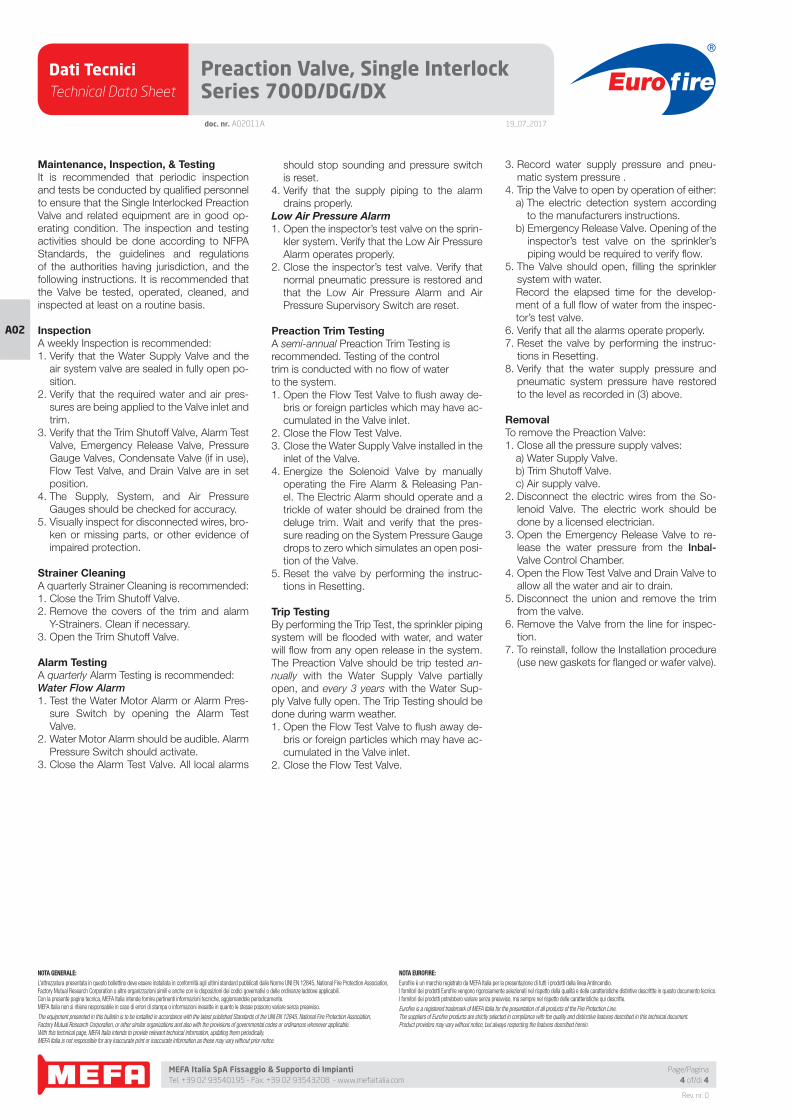
Dati TecniciTechnical Data Sheet
19_07_2017
Euro fire
MEFA Italia SpA Fissaggio & Supporto di Impianti Tel. +39 02 93540195 - Fax. +39 02 93543208 - www.mefaitalia.com
NOTA GENERALE:
L’attrezzatura presentata in questo bollettino deve essere installata in conformità agli ultimi standard pubblicati dalle Norme UNI EN 12845, National Fire Protection Association, Factory Mutual Research Corporation o altre organizzazioni simili e anche con le disposizioni dei codici governativi o delle ordinanze laddove applicabili.Con la presente pagina tecnica, MEFA Italia intende fornire pertinenti informazioni tecniche, aggiornandole periodicamente.MEFA Italia non si ritiene responsabile in caso di errori di stampa o informazioni inesatte in quanto le stesse possono variare senza preavviso.
The equipment presented in this bulletin is to be installed in accordance with the latest published Standards of the UNI EN 12845, National Fire Protection Association, Factory Mutual Research Corporation, or other similar organizations and also with the provisions of governmental codes or ordinances whenever applicable.With this technical page, MEFA Italia intends to provide relevant technical information, updating them periodically.MEFA Italia is not responsible for any inaccurate print or inaccurate information as these may vary without prior notice.
NOTA EUROFIRE:
Eurofi re è un marchio registrato da MEFA Italia per la presentazione di tutti i prodotti della linea Antincendio.I fornitori dei prodotti Eurofi re vengono rigorosamente selezionati nel rispetto della qualità e delle caratteristiche distintive descrittte in questo documento tecnico.I fornitori dei prodotti potrebbero variare senza preavviso, ma sempre nel rispetto delle caratteristiche qui descritte.
Eurofi re is a registered trademark of MEFA Italia for the presentation of all products of the Fire Protection Line.The suppliers of Eurofi re products are strictly selected in compliance with the quality and distinctive features described in this technical document.Product providers may vary without notice, but always respecting the features described herein.
Rev. nr. 0
A02
Page/Pagina4 of/di 4
Preaction Valve, Single Interlock Series 700D/DG/DX doc. nr. A02011A
Maintenance, Inspection, & TestingIt is recommended that periodic inspection
and tests be conducted by qualifi ed personnel
to ensure that the Single Interlocked Preaction
Valve and related equipment are in good op-
erating condition. The inspection and testing
activities should be done according to NFPA
Standards, the guidelines and regulations
of the authorities having jurisdiction, and the
following instructions. It is recommended that
the Valve be tested, operated, cleaned, and
inspected at least on a routine basis.
InspectionA weekly Inspection is recommended:
1. Verify that the Water Supply Valve and the
air system valve are sealed in fully open po-
sition.
2. Verify that the required water and air pres-
sures are being applied to the Valve inlet and
trim.
3. Verify that the Trim Shutoff Valve, Alarm Test
Valve, Emergency Release Valve, Pressure
Gauge Valves, Condensate Valve (if in use),
Flow Test Valve, and Drain Valve are in set
position.
4. The Supply, System, and Air Pressure
Gauges should be checked for accuracy.
5. Visually inspect for disconnected wires, bro-
ken or missing parts, or other evidence of
impaired protection.
Strainer CleaningA quarterly Strainer Cleaning is recommended:
1. Close the Trim Shutoff Valve.
2. Remove the covers of the trim and alarm
Y-Strainers. Clean if necessary.
3. Open the Trim Shutoff Valve.
Alarm TestingA quarterly Alarm Testing is recommended:
Water Flow Alarm1. Test the Water Motor Alarm or Alarm Pres-
sure Switch by opening the Alarm Test
Valve.
2. Water Motor Alarm should be audible. Alarm
Pressure Switch should activate.
3. Close the Alarm Test Valve. All local alarms
should stop sounding and pressure switch
is reset.
4. Verify that the supply piping to the alarm
drains properly.
Low Air Pressure Alarm1. Open the inspector’s test valve on the sprin-
kler system. Verify that the Low Air Pressure
Alarm operates properly.
2. Close the inspector’s test valve. Verify that
normal pneumatic pressure is restored and
that the Low Air Pressure Alarm and Air
Pressure Supervisory Switch are reset.
Preaction Trim TestingA semi-annual Preaction Trim Testing is
recommended. Testing of the control
trim is conducted with no fl ow of water
to the system.
1. Open the Flow Test Valve to fl ush away de-
bris or foreign particles which may have ac-
cumulated in the Valve inlet.
2. Close the Flow Test Valve.
3. Close the Water Supply Valve installed in the
inlet of the Valve.
4. Energize the Solenoid Valve by manually
operating the Fire Alarm & Releasing Pan-
el. The Electric Alarm should operate and a
trickle of water should be drained from the
deluge trim. Wait and verify that the pres-
sure reading on the System Pressure Gauge
drops to zero which simulates an open posi-
tion of the Valve.
5. Reset the valve by performing the instruc-
tions in Resetting.
Trip TestingBy performing the Trip Test, the sprinkler piping
system will be fl ooded with water, and water
will fl ow from any open release in the system.
The Preaction Valve should be trip tested an-
nually with the Water Supply Valve partially
open, and every 3 years with the Water Sup-
ply Valve fully open. The Trip Testing should be
done during warm weather.
1. Open the Flow Test Valve to fl ush away de-
bris or foreign particles which may have ac-
cumulated in the Valve inlet.
2. Close the Flow Test Valve.
3. Record water supply pressure and pneu-
matic system pressure .
4. Trip the Valve to open by operation of either:
a) The electric detection system according
to the manufacturers instructions.
b) Emergency Release Valve. Opening of the
inspector’s test valve on the sprinkler’s
piping would be required to verify fl ow.
5. The Valve should open, fi lling the sprinkler
system with water.
Record the elapsed time for the develop-
ment of a full fl ow of water from the inspec-
tor’s test valve.
6. Verify that all the alarms operate properly.
7. Reset the valve by performing the instruc-
tions in Resetting.
8. Verify that the water supply pressure and
pneumatic system pressure have restored
to the level as recorded in (3) above.
RemovalTo remove the Preaction Valve:
1. Close all the pressure supply valves:
a) Water Supply Valve.
b) Trim Shutoff Valve.
c) Air supply valve.
2. Disconnect the electric wires from the So-
lenoid Valve. The electric work should be
done by a licensed electrician.
3. Open the Emergency Release Valve to re-
lease the water pressure from the Inbal-Valve Control Chamber.
4. Open the Flow Test Valve and Drain Valve to
allow all the water and air to drain.
5. Disconnect the union and remove the trim
from the valve.
6. Remove the Valve from the line for inspec-
tion.
7. To reinstall, follow the Installation procedure
(use new gaskets for fl anged or wafer valve).
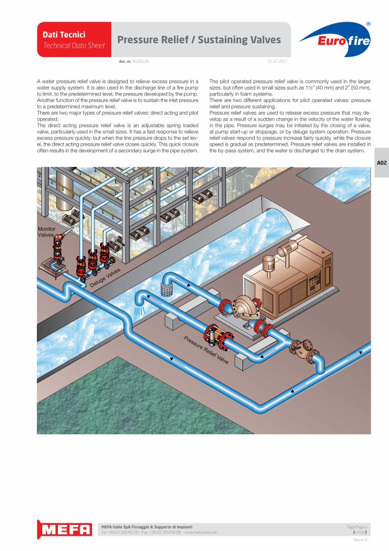
Dati TecniciTechnical Data Sheet
19_07_2017
Euro fire
MEFA Italia SpA Fissaggio & Supporto di Impianti Tel. +39 02 93540195 - Fax. +39 02 93543208 - www.mefaitalia.com
Rev. nr. 0
A02
Page/Pagina1 of/di 2
doc. nr. A02012A
Pressure Relief / Sustaining Valves
Pressure Relief Valve
Deluge Valves
MonitorValves
A water pressure relief valve is designed to relieve excess pressure in a
water supply system. It is also used in the discharge line of a fi re pump
to limit, to the predetermined level, the pressure developed by the pump.
Another function of the pressure relief valve is to sustain the inlet pressure
to a predetermined maximum level.
There are two major types of pressure relief valves: direct acting and pilot
operated.
The direct acting pressure relief valve is an adjustable spring loaded
valve, particularly used in the small sizes. It has a fast response to relieve
excess pressure quickly; but when the line pressure drops to the set lev-
el, the direct acting pressure relief valve closes quickly. This quick closure
often results in the development of a secondary surge in the pipe system.
The pilot operated pressure relief valve is commonly used in the larger
sizes, but often used in small sizes such as 1½” (40 mm) and 2” (50 mm),
particularly in foam systems.
There are two different applications for pilot operated valves: pressure
relief and pressure sustaining.
Pressure relief valves are used to release excess pressure that may de-
velop as a result of a sudden change in the velocity of the water fl owing
in the pipe. Pressure surges may be initiated by the closing of a valve,
at pump start-up or stoppage, or by deluge system operation. Pressure
relief valves respond to pressure increase fairly quickly, while the closure
speed is gradual as predetermined. Pressure relief valves are installed in
the by-pass system, and the water is discharged to the drain system.
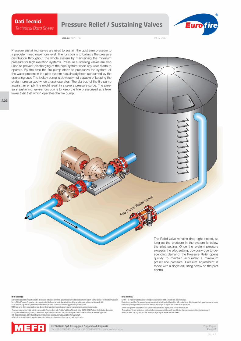
Dati TecniciTechnical Data Sheet
19_07_2017
Euro fire
MEFA Italia SpA Fissaggio & Supporto di Impianti Tel. +39 02 93540195 - Fax. +39 02 93543208 - www.mefaitalia.com
NOTA GENERALE:
L’attrezzatura presentata in questo bollettino deve essere installata in conformità agli ultimi standard pubblicati dalle Norme UNI EN 12845, National Fire Protection Association, Factory Mutual Research Corporation o altre organizzazioni simili e anche con le disposizioni dei codici governativi o delle ordinanze laddove applicabili.Con la presente pagina tecnica, MEFA Italia intende fornire pertinenti informazioni tecniche, aggiornandole periodicamente.MEFA Italia non si ritiene responsabile in caso di errori di stampa o informazioni inesatte in quanto le stesse possono variare senza preavviso.
The equipment presented in this bulletin is to be installed in accordance with the latest published Standards of the UNI EN 12845, National Fire Protection Association, Factory Mutual Research Corporation, or other similar organizations and also with the provisions of governmental codes or ordinances whenever applicable.With this technical page, MEFA Italia intends to provide relevant technical information, updating them periodically.MEFA Italia is not responsible for any inaccurate print or inaccurate information as these may vary without prior notice.
NOTA EUROFIRE:
Eurofi re è un marchio registrato da MEFA Italia per la presentazione di tutti i prodotti della linea Antincendio.I fornitori dei prodotti Eurofi re vengono rigorosamente selezionati nel rispetto della qualità e delle caratteristiche distintive descrittte in questo documento tecnico.I fornitori dei prodotti potrebbero variare senza preavviso, ma sempre nel rispetto delle caratteristiche qui descritte.
Eurofi re is a registered trademark of MEFA Italia for the presentation of all products of the Fire Protection Line.The suppliers of Eurofi re products are strictly selected in compliance with the quality and distinctive features described in this technical document.Product providers may vary without notice, but always respecting the features described herein.
Rev. nr. 0
A02
Page/Pagina2 of/di 2
Pressure Relief / Sustaining Valves
doc. nr. A02012A
Pressure sustaining valves are used to sustain the upstream pressure to
a predetermined maximum level. The function is to balance the pressure
distribution throughout the whole system by maintaining the minimum
pressure for high elevation systems. Pressure sustaining valves are also
used to prevent discharging of the pipe system when any user starts to
operate. By the time the fi re pump starts to pressurize the system, all
the water present in the pipe system has already been consumed by the
operating user. The jockey pump is obviously not capable of keeping the
system pressurized when a user operates. The start-up of the fi re pump
against an empty line might result in a severe pressure surge. The pres-
sure sustaining valve’s function is to keep the line pressurized at a level
lower than that which operates the fi re pump.
Pressure sustaining valves are used to sustain the upstream pressure to a predetermined maximum level. The function is to balance the pressure distribution throughout the whole system by maintaining the minimum pressure for high elevation systems. Pressure sustaining valves are also used to prevent discharging of the pipe system when any user starts to operate. By the time the fire pump starts to pressurize the system, all the water present in the pipe system has already been consumed by the operating user. The jockey pump is obviously not capable of keeping the system pressurized when a user operates. The start-up of the fire pump against an empty line might result in a severe pressure surge. The pressure sustaining valve's function is to keep the line pressurized at a level lower than that which operates the fire pump.
The Inbal Relief valve remains drop-tight closed, as long as the
pressure in the system is below the pilot setting. Once the system pressure
exceeds the pilot setting, obviously due to descending demand, the Inbal PressureRelief opens quickly to maintain accurately a maximum preset line pressure. Pressure adjustment is made with a single adjusting screw on the pilot control.
Fire Pump Relief Valve
The Relief valve remains drop-tight closed, as
long as the pressure in the system is below
the pilot setting. Once the system pressure
exceeds the pilot setting, obviously due to de-
scending demand, the Pressure Relief opens
quickly to maintain accurately a maximum
preset line pressure. Pressure adjustment is
made with a single adjusting screw on the pilot
control.
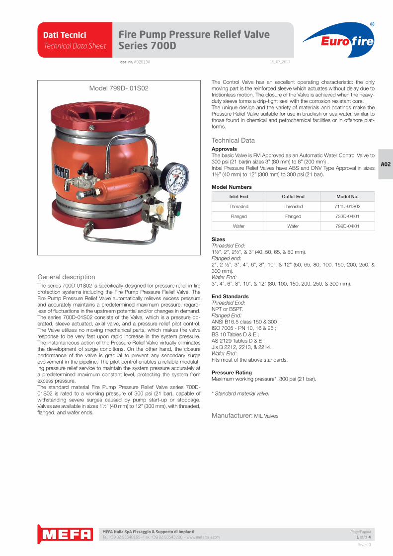
Dati TecniciTechnical Data Sheet
19_07_2017
Euro fire
MEFA Italia SpA Fissaggio & Supporto di Impianti Tel. +39 02 93540195 - Fax. +39 02 93543208 - www.mefaitalia.com
Rev. nr. 0
A02
Page/Pagina1 of/di 4
doc. nr. A02013A
Fire Pump Pressure Relief Valve Series 700D
General description
The series 700D-01S02 is specifi cally designed for pressure relief in fi re
protection systems including the Fire Pump Pressure Relief Valve. The
Fire Pump Pressure Relief Valve automatically relieves excess pressure
and accurately maintains a predetermined maximum pressure, regard-
less of fl uctuations in the upstream potential and/or changes in demand.
The series 700D-01S02 consists of the Valve, which is a pressure op-
erated, sleeve actuated, axial valve, and a pressure relief pilot control.
The Valve utilizes no moving mechanical parts, which makes the valve
response to be very fast upon rapid increase in the system pressure.
The instantaneous action of the Pressure Relief Valve virtually eliminates
the development of surge conditions. On the other hand, the closure
performance of the valve is gradual to prevent any secondary surge
evolvement in the pipeline. The pilot control enables a reliable modulat-
ing pressure relief service to maintain the system pressure accurately at
a predetermined maximum constant level, protecting the system from
excess pressure.
The standard material Fire Pump Pressure Relief Valve series 700D-
01S02 is rated to a working pressure of 300 psi (21 bar), capable of
withstanding severe surges caused by pump start-up or stoppage.
Valves are available in sizes 1½” (40 mm) to 12” (300 mm), with threaded,
fl anged, and wafer ends.
The Control Valve has an excellent operating characteristic: the only
moving part is the reinforced sleeve which actuates without delay due to
frictionless motion. The closure of the Valve is achieved when the heavy-
duty sleeve forms a drip-tight seal with the corrosion resistant core.
The unique design and the variety of materials and coatings make the
Pressure Relief Valve suitable for use in brackish or sea water, similar to
those found in chemical and petrochemical facilities or in offshore plat-
forms.
Technical Data
ApprovalsThe basic Valve is FM Approved as an Automatic Water Control Valve to
300 psi (21 bar)in sizes 3” (80 mm) to 8” (200 mm) .
Inbal Pressure Relief Valves have ABS and DNV Type Approval in sizes
1½” (40 mm) to 12” (300 mm) to 300 psi (21 bar).
Model Numbers
Inlet End Outlet End Model No.
Threaded Threaded 711D-01S02
Flanged Flanged 733D-04I01
Wafer Wafer 799D-04I01
SizesThreaded End:
1½”, 2”, 2½”, & 3” (40, 50, 65, & 80 mm).
Flanged end:
2”, 2 ½”, 3”, 4”, 6”, 8”, 10”, & 12” (50, 65, 80, 100, 150, 200, 250, &
300 mm).
Wafer End:
3”, 4”, 6”, 8”, 10”, & 12” (80, 100, 150, 200, 250, & 300 mm).
End StandardsThreaded End:
NPT or BSPT.
Flanged End:
ANSI B16.5 class 150 & 300 ;
ISO 7005 - PN 10, 16 & 25 ;
BS 10 Tables D & E ;
AS 2129 Tables D & E ;
Jis B 2212, 2213, & 2214.
Wafer End:
Fits most of the above standards.
Pressure RatingMaximum working pressure*: 300 psi (21 bar).
* Standard material valve.
Manufacturer: MIL Valves
Model 799D- 01S02
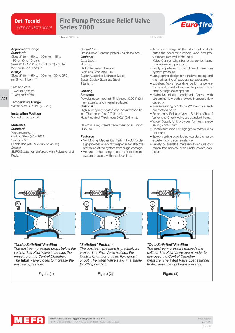
Dati TecniciTechnical Data Sheet
19_07_2017
Euro fire
MEFA Italia SpA Fissaggio & Supporto di Impianti Tel. +39 02 93540195 - Fax. +39 02 93543208 - www.mefaitalia.com
Rev. nr. 0
A02
doc. nr. A02013A
Fire Pump Pressure Relief Valve Series 700D
Page/Pagina2 of/di 4
Adjustment RangeStandard:Sizes 2” to 4” (50 to 100 mm) - 45 to
190 psi (3 to 13 bar).*
Sizes 6” to 12” (150 to 300 mm) - 60 to
270 psi (4 to 19 bar).**
Heavy:Sizes 2” to 4” (50 to 100 mm) 130 to 270
psi (9 to 19 bar).***
* Marked blue.
** Marked yellow.
*** Marked white.
Temperature RangeWater: Max. +150oF (+65oC).
Installation PositionVertical or horizontal.
MaterialsStandardValve Housing:
Carbon Steel (SAE 1021).
Valve Ends :
Ductile Iron (ASTM A536-65 45 12).
Sleeve:
SMR5 Elastomer reinforced with Polyester and
Kevlar.
Control Trim:
Brass Nickel Chrome plated, Stainless Steel.
OptionalCast Steel ;
Bronze ;
Nickel Aluminum Bronze ;
Stainless Steel AISI 316 ;
Super Austenitic Stainless Steel ;
Super Duplex Stainless Steel ;
Titanium.
CoatingStandardPowder epoxy coated. Thickness: 0.004” (0.1
mm) external and internal surfaces.
OptionalHigh built epoxy coated and polyurethane fi n-
ish. Thickness: 0.01” (0.3 mm).
Halar® coated. Thickness: 0.02” (0.5 mm).
Halar® is a registered trade mark of Ausimont
USA Inc.
Features• No Moving Mechanical Parts (N.M.M.P.) de-
sign provides a very fast response for effective
protection of the system from surge damage.
• Accurate modulating action to maintain the
system pressure within a close limit.
• Advanced design of the pilot control elimi-
nates the need for a needle valve and pro-
vides fast removal of the Inbal
Valve Control Chamber pressure for faster
pressure relief operation.
• Easily adjustable to the desired maximum
system pressure.
• Long spring design for sensitive setting and
the maintaining of accurate set pressure.
• Excellent Valve regulating performance en-
sures soft, gradual closure to prevent sec-
ondary surge development.
• Hydrodynamically designed Valve with
streamline fl ow path provides increased fl ow
capacity.
• Pressure rating of 300 psi (21 bar) for stand-
ard material valve.
• Emergency Release Valve, Strainer, Shutoff
Valve, and Check Valve are standard items.
• Water Supply Unit provides for neat, space
saving control trim.
• Control trim made of high grade materials as
standard.
• Epoxy coating supplied as standard ensures
excellent corrosion resistance.
• Variety of available materials to ensure cor-
rosion-free service, even under severe con-
ditions.
"Under Satisfied" PositionThe upstream pressure drops below the setting. The Pilot Valve increases the pressure at the Control Chamber. The Inbal Valve closes to increase the upstream pressure.
"Over Satisfied" PositionThe upstream pressure exceeds the setting. The Pilot Valve opens wider to decrease the Control Chamber pressure. The Inbal Valve opens further to decrease the upstream pressure.
"Satisfied" Position The upstream pressure is precisely as preset. The Pilot Valve isolates the Control Chamber thus no flow goes in or out. The Inbal Valve stays in a stable throttling position.
Figure (1) Figure (2) Figure (3)
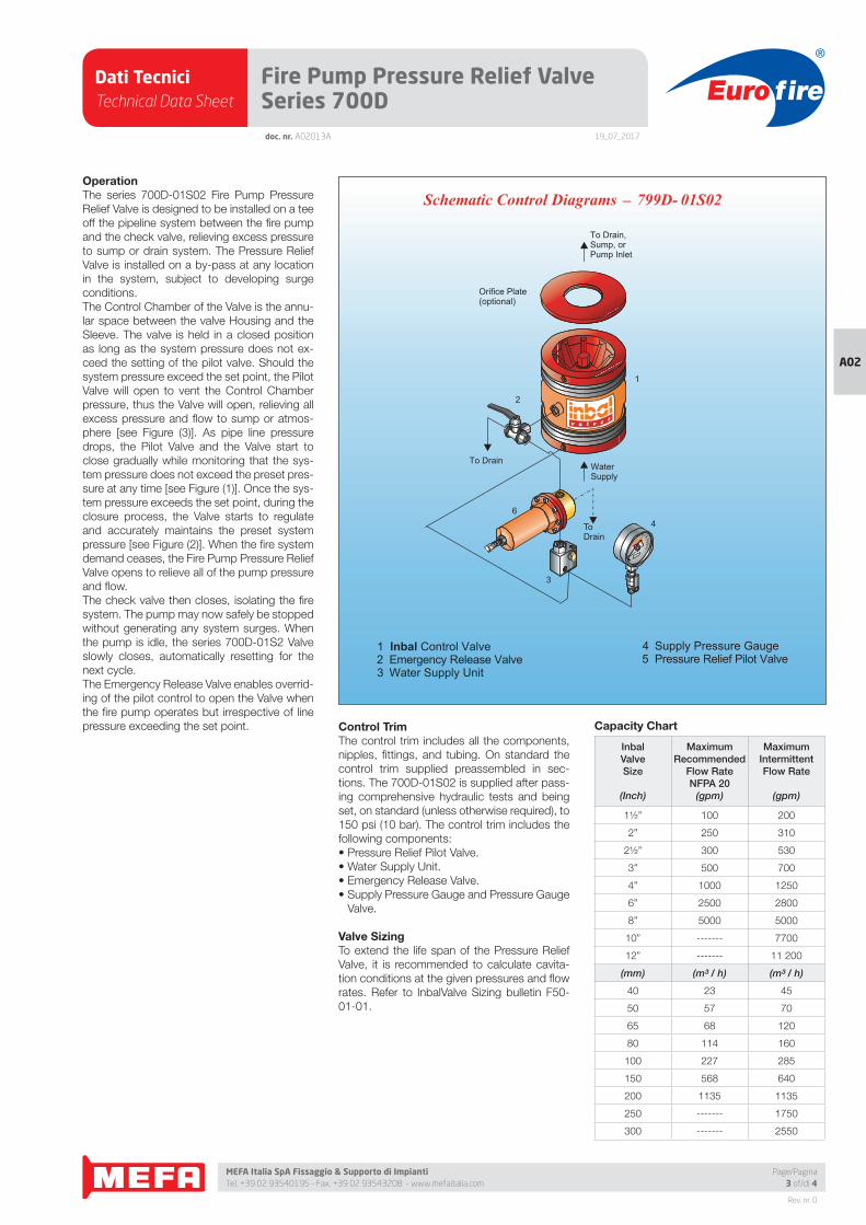
Dati TecniciTechnical Data Sheet
19_07_2017
Euro fire
MEFA Italia SpA Fissaggio & Supporto di Impianti Tel. +39 02 93540195 - Fax. +39 02 93543208 - www.mefaitalia.com
Rev. nr. 0
A02
Page/Pagina3 of/di 4
doc. nr. A02013A
Fire Pump Pressure Relief Valve Series 700D
OperationThe series 700D-01S02 Fire Pump Pressure
Relief Valve is designed to be installed on a tee
off the pipeline system between the fi re pump
and the check valve, relieving excess pressure
to sump or drain system. The Pressure Relief
Valve is installed on a by-pass at any location
in the system, subject to developing surge
conditions.
The Control Chamber of the Valve is the annu-
lar space between the valve Housing and the
Sleeve. The valve is held in a closed position
as long as the system pressure does not ex-
ceed the setting of the pilot valve. Should the
system pressure exceed the set point, the Pilot
Valve will open to vent the Control Chamber
pressure, thus the Valve will open, relieving all
excess pressure and fl ow to sump or atmos-
phere [see Figure (3)]. As pipe line pressure
drops, the Pilot Valve and the Valve start to
close gradually while monitoring that the sys-
tem pressure does not exceed the preset pres-
sure at any time [see Figure (1)]. Once the sys-
tem pressure exceeds the set point, during the
closure process, the Valve starts to regulate
and accurately maintains the preset system
pressure [see Figure (2)]. When the fi re system
demand ceases, the Fire Pump Pressure Relief
Valve opens to relieve all of the pump pressure
and fl ow.
The check valve then closes, isolating the fi re
system. The pump may now safely be stopped
without generating any system surges. When
the pump is idle, the series 700D-01S2 Valve
slowly closes, automatically resetting for the
next cycle.
The Emergency Release Valve enables overrid-
ing of the pilot control to open the Valve when
the fi re pump operates but irrespective of line
pressure exceeding the set point. Control TrimThe control trim includes all the components,
nipples, fi ttings, and tubing. On standard the
control trim supplied preassembled in sec-
tions. The 700D-01S02 is supplied after pass-
ing comprehensive hydraulic tests and being
set, on standard (unless otherwise required), to
150 psi (10 bar). The control trim includes the
following components:
• Pressure Relief Pilot Valve.
• Water Supply Unit.
• Emergency Release Valve.
• Supply Pressure Gauge and Pressure Gauge
Valve.
Valve SizingTo extend the life span of the Pressure Relief
Valve, it is recommended to calculate cavita-
tion conditions at the given pressures and fl ow
rates. Refer to InbalValve Sizing bulletin F50-
01-01.
Capacity Chart
InbalValveSize
(Inch)
MaximumRecommended
Flow RateNFPA 20
(gpm)
MaximumIntermittentFlow Rate
(gpm)
1½” 100 200
2” 250 310
2½” 300 530
3” 500 700
4” 1000 1250
6” 2500 2800
8” 5000 5000
10” ------- 7700
12” ------- 11 200
(mm) (m³ / h) (m³ / h)
40 23 45
50 57 70
65 68 120
80 114 160
100 227 285
150 568 640
200 1135 1135
250 ------- 1750
300 ------- 2550
_Schematic Control Diagrams 799D- 01S02
1 Inbal Control Valve2 Emergency Release Valve
Water Supply Unit3
4 Supply Pressure Gauge 5 Pressure Relief Pilot Valve
ToDrain
WaterSupply
To Drain,Sump, orPump Inlet
To Drain
Orifice Plate(optional)
3
2
1
64
Dati TecniciTechnical Data Sheet
19_07_2017
Euro fire
MEFA Italia SpA Fissaggio & Supporto di Impianti Tel. +39 02 93540195 - Fax. +39 02 93543208 - www.mefaitalia.com
NOTA GENERALE:
L’attrezzatura presentata in questo bollettino deve essere installata in conformità agli ultimi standard pubblicati dalle Norme UNI EN 12845, National Fire Protection Association, Factory Mutual Research Corporation o altre organizzazioni simili e anche con le disposizioni dei codici governativi o delle ordinanze laddove applicabili.Con la presente pagina tecnica, MEFA Italia intende fornire pertinenti informazioni tecniche, aggiornandole periodicamente.MEFA Italia non si ritiene responsabile in caso di errori di stampa o informazioni inesatte in quanto le stesse possono variare senza preavviso.
The equipment presented in this bulletin is to be installed in accordance with the latest published Standards of the UNI EN 12845, National Fire Protection Association, Factory Mutual Research Corporation, or other similar organizations and also with the provisions of governmental codes or ordinances whenever applicable.With this technical page, MEFA Italia intends to provide relevant technical information, updating them periodically.MEFA Italia is not responsible for any inaccurate print or inaccurate information as these may vary without prior notice.
NOTA EUROFIRE:
Eurofi re è un marchio registrato da MEFA Italia per la presentazione di tutti i prodotti della linea Antincendio.I fornitori dei prodotti Eurofi re vengono rigorosamente selezionati nel rispetto della qualità e delle caratteristiche distintive descrittte in questo documento tecnico.I fornitori dei prodotti potrebbero variare senza preavviso, ma sempre nel rispetto delle caratteristiche qui descritte.
Eurofi re is a registered trademark of MEFA Italia for the presentation of all products of the Fire Protection Line.The suppliers of Eurofi re products are strictly selected in compliance with the quality and distinctive features described in this technical document.Product providers may vary without notice, but always respecting the features described herein.
Rev. nr. 0
A02
Page/Pagina4 of/di 4
Fire Pump Pressure Relief Valve Series 700Ddoc. nr. A02013A
InstallationRefer to the Trim Chart applicable to the Pres-
sure Relief Valve model in use. The valve must
be installed in an area not subject to freezing
temperatures or physical damage. The Valve
series 700D-01S02 can be installed horizon-
tally or vertically.
1. When the Pressure Relief Valve is delivered,
carefully unpack and check that there has
been no damage to the operating compo-
nents, piping, and fi ttings.
2. Always fl ush the pipeline before installing the
Valve.
3. Place the Valve in the piping at the outlet of
the tee. Verify that the arrow on the Pressure
Relief Valve matches the actual fl ow direc-
tion. Determine from which side the system
will be accessed, and locate the Valve on
the piping system accordingly.
4. Install the Pressure Relief Valve in the pipe-
line. Use tape, gaskets, bolts, stud bolts,
bolt sleeves, and nuts as required by the
specifi c Valve model in use.
5. Complete the trim assembly by mounting
the preassembled sections.
Refer to the applicable Trim Chart and In-
structions
6. Connect the drain port of the Pressure Relief
Pilot Valve to the drainage system.
7. Open the shutoff valve. To ensure smooth
operation, all air must be expelled from the
Valve Control Chamber and pilot control
system.
8. If adjustment is required see (3) in Resetting
9. Test the Pressure Relief Valve according to
the Testing procedure.
Resetting1. During normal course of operation, the
Pressure Relief Valve is automatically reset
after operation.
2. If the Valve was actuated by the Emergen-
cy Release Valve, the handle of the valve
should be returned to SET position.
3. If the relieved set point pressure is to be ad-
justed, turn the Pilot Valve adjusting screw
clockwise to increase and counter-clock-
wise to reduce the pressure setting.
Maintenance, Inspection, & TestingIt is recommended that periodic inspections
and tests be conducted by qualifi ed personnel
to ensure that the Pressure Relief Valve is in
good operating condition. The inspection and
testing activities should be done according to
NFPA standards, the guidelines and regula-
tions of the authorities having jurisdiction, and
the following instructions. It is recommended
that the Pressure Relief Valve be tested, op-
erated, cleaned, and inspected on a routine
basis.
InspectionA monthly inspection is recommended:
1. Check the Supply Pressure Gauge reading.
2. Verify that the Shutoff Valve device is in SET
position.
3. Verify that the Emergency Release Valve is
in SET position.
4. Verify that the Pilot Valve and the Valve are
tightly closed.
5. Visually inspect for broken or missing parts,
or other evidence of impaired protection.
Strainer CleaningA quarterly strainer cleaning is recommended:
1. Close the Shutoff Valve device (turn the Ro-
tor to MAINTENANCE position).
2. Remove the cover of the strainer device in
the Water Supply Unit, clean if necessary.
Reinstall the screen and the cover.
3. Open the Shutoff Valve device (return the
Rotor to SET position).
Pressure Relief Valve TestingA semi-annual Pressure Relief Valve Testing is
recommended:
1. The testing of the valve involves the opera-
tion of the Fire Pump. If testing of the entire
system is not feasible, then the Main Shutoff
Valve should be closed before the pump is
activated.
The Pressure Relief Valve is sized to have
the capability of relieving the full pump ca-
pacity at the predetermined system pres-
sure.
2. When the pump is on, verify that the Pilot
Valve and the Valve are open and that the
pump delivery pressure is maintained at the
preset level.
3. When the pump is stopped verify that both
the Pilot Valve and the Valve gradually close
to a drip tight position.
Pilot Valve TestingOperation of the Pilot Valve should be done
quarterly. If operation of the entire system is
not feasible, then an individual pilot testing
should be performed.
Testing of the Pilot Valve should be done by
following the instructions in bulletin F36-05-
01 - “Pressure Relief Pilot Valve models PN2
& PO2”.
RemovalTo remove the Pressure Relief Valve:
1. Close the Main Shutoff Valve.
2. Open the Emergency Release Valve to re-
lease the water pressure from the Valve
Control Chamber.
3. Remove the Pressure Relief Valve from the
line for inspection.
4. To reinstall, follow the installation procedure
(use new gaskets for fl anged or wafer valve).
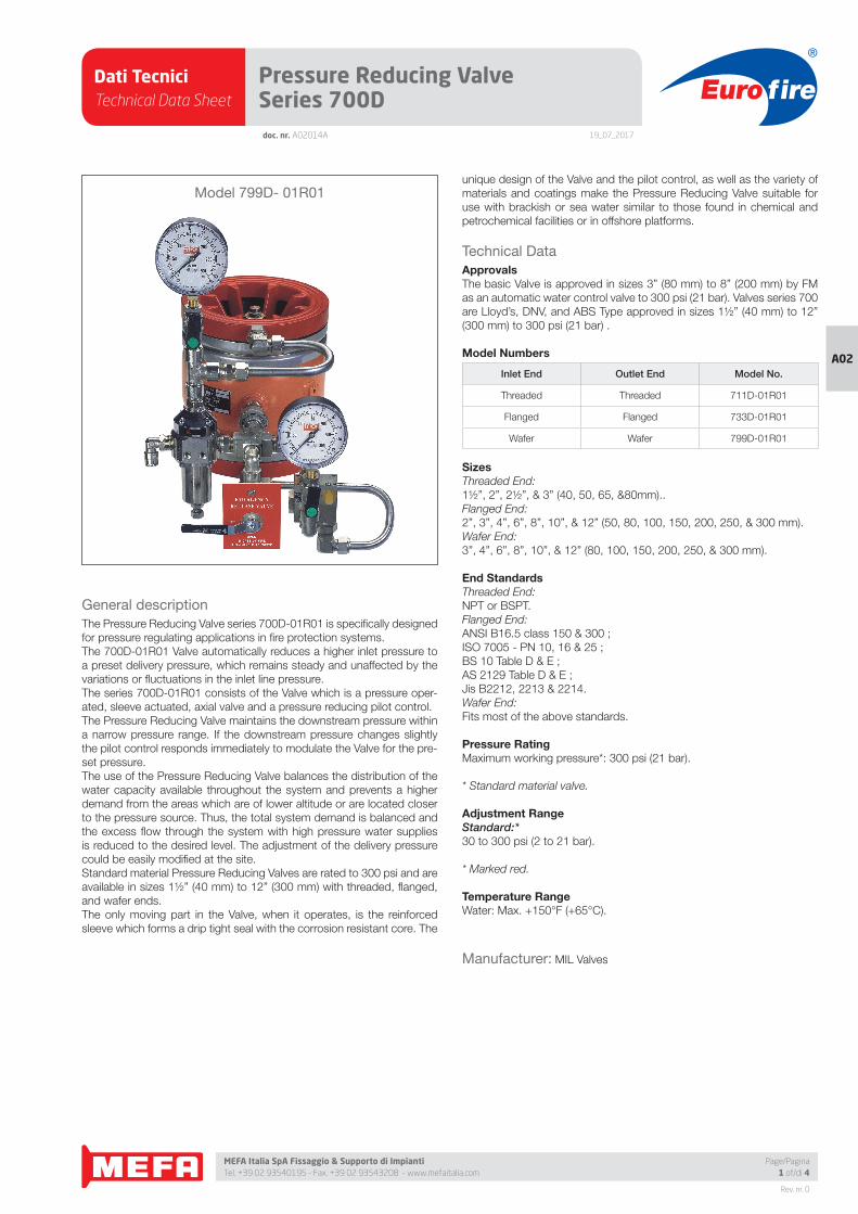
Dati TecniciTechnical Data Sheet
19_07_2017
Euro fire
MEFA Italia SpA Fissaggio & Supporto di Impianti Tel. +39 02 93540195 - Fax. +39 02 93543208 - www.mefaitalia.com
Rev. nr. 0
A02
Page/Pagina1 of/di 4
doc. nr. A02014A
Pressure Reducing Valve Series 700D
General description
The Pressure Reducing Valve series 700D-01R01 is specifi cally designed
for pressure regulating applications in fi re protection systems.
The 700D-01R01 Valve automatically reduces a higher inlet pressure to
a preset delivery pressure, which remains steady and unaffected by the
variations or fl uctuations in the inlet line pressure.
The series 700D-01R01 consists of the Valve which is a pressure oper-
ated, sleeve actuated, axial valve and a pressure reducing pilot control.
The Pressure Reducing Valve maintains the downstream pressure within
a narrow pressure range. If the downstream pressure changes slightly
the pilot control responds immediately to modulate the Valve for the pre-
set pressure.
The use of the Pressure Reducing Valve balances the distribution of the
water capacity available throughout the system and prevents a higher
demand from the areas which are of lower altitude or are located closer
to the pressure source. Thus, the total system demand is balanced and
the excess fl ow through the system with high pressure water supplies
is reduced to the desired level. The adjustment of the delivery pressure
could be easily modifi ed at the site.
Standard material Pressure Reducing Valves are rated to 300 psi and are
available in sizes 1½” (40 mm) to 12” (300 mm) with threaded, fl anged,
and wafer ends.
The only moving part in the Valve, when it operates, is the reinforced
sleeve which forms a drip tight seal with the corrosion resistant core. The
unique design of the Valve and the pilot control, as well as the variety of
materials and coatings make the Pressure Reducing Valve suitable for
use with brackish or sea water similar to those found in chemical and
petrochemical facilities or in offshore platforms.
Technical Data
ApprovalsThe basic Valve is approved in sizes 3” (80 mm) to 8” (200 mm) by FM
as an automatic water control valve to 300 psi (21 bar). Valves series 700
are Lloyd’s, DNV, and ABS Type approved in sizes 1½” (40 mm) to 12”
(300 mm) to 300 psi (21 bar) .
Model Numbers
Inlet End Outlet End Model No.
Threaded Threaded 711D-01R01
Flanged Flanged 733D-01R01
Wafer Wafer 799D-01R01
SizesThreaded End:
1½”, 2”, 2½”, & 3” (40, 50, 65, &80mm)..
Flanged End:
2”, 3”, 4”, 6”, 8”, 10”, & 12” (50, 80, 100, 150, 200, 250, & 300 mm).
Wafer End:
3”, 4”, 6”, 8”, 10”, & 12” (80, 100, 150, 200, 250, & 300 mm).
End StandardsThreaded End:
NPT or BSPT.
Flanged End:
ANSI B16.5 class 150 & 300 ;
ISO 7005 - PN 10, 16 & 25 ;
BS 10 Table D & E ;
AS 2129 Table D & E ;
Jis B2212, 2213 & 2214.
Wafer End:
Fits most of the above standards.
Pressure RatingMaximum working pressure*: 300 psi (21 bar).
* Standard material valve.
Adjustment RangeStandard:*30 to 300 psi (2 to 21 bar).
* Marked red.
Temperature RangeWater: Max. +150°F (+65°C).
Manufacturer: MIL Valves
Model 799D- 01R01
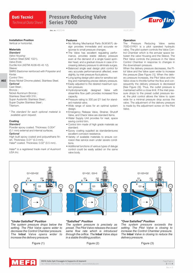
Dati TecniciTechnical Data Sheet
19_07_2017
Euro fire
MEFA Italia SpA Fissaggio & Supporto di Impianti Tel. +39 02 93540195 - Fax. +39 02 93543208 - www.mefaitalia.com
Rev. nr. 0
A02
doc. nr. A02014A
Pressure Reducing Valve Series 700D
Page/Pagina2 of/di 4
Installation PositionVertical or horizontal.
MaterialsStandardValve Housing:
Carbon Steel (SAE 1021).
Valve Ends:
Ductile Iron (ASTM A536-65 45 12).
Sleeve:
SMR5 Elastomer reinforced with Polyester and
Kevlar.
Control Trim:
Brass Nickel Chrome plated, Stainless Steel.
OptionalCast Steel ;
Bronze ;
Nickel Aluminum Bronze ;
Stainless Steel AISI 316 ;
Super Austenitic Stainless Steel ;
Super Duplex Stainless Steel ;
Titanium.
* The standard for each optional material is
available upon request.
CoatingStandardPowder epoxy coated. Thickness: 0.004”
(0.1 mm) external and internal surfaces.
OptionalHigh built epoxy coated and polyurethane fi n-
ish. Thickness: 0.01” (0.3 mm).
Halar® coated. Thickness: 0.02” (0.5 mm) .
Halar® is a registered trade mark of Ausimont
USA Inc.
Features• No Moving Mechanical Parts (N.M.M.P.) de-
sign provides immediate and accurate re-
sponse to small pressure changes.
• The Valve has excellent regulating perfor-
mance, provides stable delivery pressure
even at the demand of a single fused sprin-
kler head, and a gradual closure in case of in-
creasing delivery pressure to eliminate surges.
• Balanced single seat design pilot control for
very accurate performancenot affected, even
slightly, by inlet pressure fl uctuations.
• Long spring design pilot valve for sensitive set-
ting and maintaining precise delivery pressure.
• Easily adjusted to the desired maximum sys-
tem pressure.
• Hydrodynamically designed Valve with
streamline fl ow path provides increased fl ow
capacity.
• Pressure rating to 300 psi (21 bar) for stand-
ard material valve.
• Wide range of sizes for an optimal system
design.
• Emergency Release Valve, Strainer, Shutoff
Valve, and Check Valve are standard items.
• Water Supply Unit provides for neat, space
saving control trim.
• Control trim made of high grade materials as
standard.
• Epoxy coating supplied as standardensures
excellent corrosion resistance.
• Variety of available materials to ensure cor-
rosion-free service even under severe condi-
tions.
• Additional functions of various types of deluge
control could be easily added on the same
valve body.
OperationThe Pressure Reducing Valve series
700D-01R01 is a pilot operated hydraulic
valve. The pilot system controls the Valve Con-
trol Chamber which is the annular space be-
tween the valve Housing and the Sleeve. The
Pilot Valve controls the pressure in the Valve
Control Chamber in response to changes in
the downstream pressure.
When the delivery pressure decreases, the Pi-
lot Valve and the Valve open wider to increase
the pressure [See Figure (1)]. When the deliv-
ery pressure increases, the Pilot Valve and the
Valve close to throttle further the fl ow and con-
sequently the delivery pressure is decreased
[See Figure (3)]. Thus, the outlet pressure is
maintained within a close limit. If the inlet pres-
sure drops to the preset outlet pressure lev-
el, the pilot control allows the Valve to open
wide for a minimal pressure drop across the
valve. The adjustment of the delivery pressure
is made by the adjustment screw on the Pilot
Valve.
"Under Satisfied" PositionThe system pressure drops below the setting. The Pilot Valve opens wider to decrease the Control Chamber pressure. The Inbal Valve opens wider to increase the delivery pressure.
"Over Satisfied" PositionThe system pressure exceeds the setting. The Pilot Valve is closing to increase the Control Chamber pressure. The Inbal Valve is closing to reduce the delivery pressure.
''Satisfied" PositionThe system pressure is precisely as preset. The Pilot Valve releases the exact same flow rate which is introduced through the orifice. The Inbal Valve stays in a stable throttling position.
Figure (1) Figure (2) Figure (3)
Q2 Q2Q2Q1 Q1 Q1
Q1=Q2 ; Q3=0Q1+Q3=Q2 Q1-Q3=Q2
Q3 Q3Q3
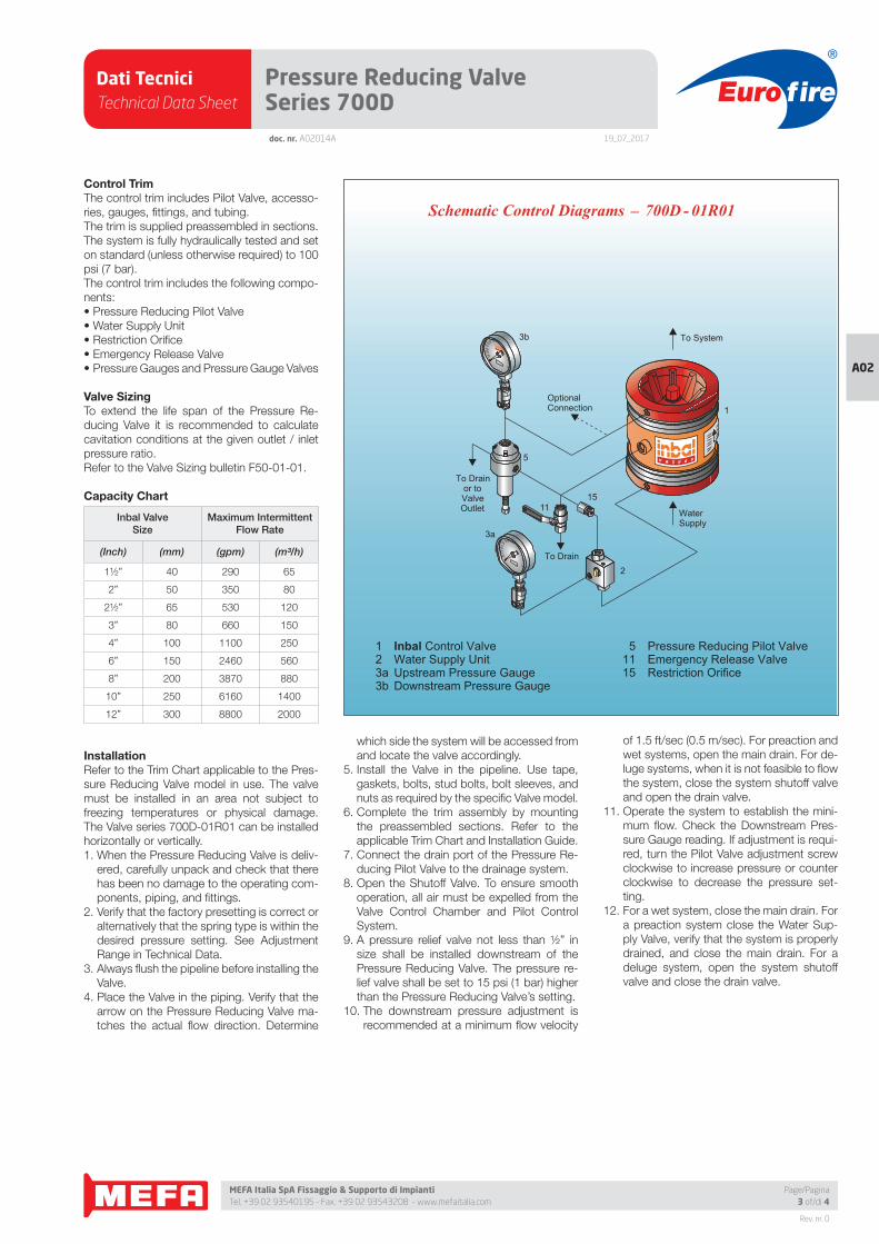
Dati TecniciTechnical Data Sheet
19_07_2017
Euro fire
MEFA Italia SpA Fissaggio & Supporto di Impianti Tel. +39 02 93540195 - Fax. +39 02 93543208 - www.mefaitalia.com
Rev. nr. 0
A02
Page/Pagina3 of/di 4
doc. nr. A02014A
Pressure Reducing Valve Series 700D
Control TrimThe control trim includes Pilot Valve, accesso-
ries, gauges, fi ttings, and tubing.
The trim is supplied preassembled in sections.
The system is fully hydraulically tested and set
on standard (unless otherwise required) to 100
psi (7 bar).
The control trim includes the following compo-
nents:
• Pressure Reducing Pilot Valve
• Water Supply Unit
• Restriction Orifi ce
• Emergency Release Valve
• Pressure Gauges and Pressure Gauge Valves
Valve SizingTo extend the life span of the Pressure Re-
ducing Valve it is recommended to calculate
cavitation conditions at the given outlet / inlet
pressure ratio.
Refer to the Valve Sizing bulletin F50-01-01.
Capacity Chart
Inbal ValveSize
Maximum IntermittentFlow Rate
(Inch) (mm) (gpm) (m³/h)
1½” 40 290 65
2” 50 350 80
2½” 65 530 120
3” 80 660 150
4” 100 1100 250
6” 150 2460 560
8” 200 3870 880
10” 250 6160 1400
12” 300 8800 2000
InstallationRefer to the Trim Chart applicable to the Pres-
sure Reducing Valve model in use. The valve
must be installed in an area not subject to
freezing temperatures or physical damage.
The Valve series 700D-01R01 can be installed
horizontally or vertically.
1. When the Pressure Reducing Valve is deliv-
ered, carefully unpack and check that there
has been no damage to the operating com-
ponents, piping, and fi ttings.
2. Verify that the factory presetting is correct or
alternatively that the spring type is within the
desired pressure setting. See Adjustment
Range in Technical Data.
3. Always fl ush the pipeline before installing the
Valve.
4. Place the Valve in the piping. Verify that the
arrow on the Pressure Reducing Valve ma-
tches the actual fl ow direction. Determine
which side the system will be accessed from
and locate the valve accordingly.
5. Install the Valve in the pipeline. Use tape,
gaskets, bolts, stud bolts, bolt sleeves, and
nuts as required by the specifi c Valve model.
6. Complete the trim assembly by mounting
the preassembled sections. Refer to the
applicable Trim Chart and Installation Guide.
7. Connect the drain port of the Pressure Re-
ducing Pilot Valve to the drainage system.
8. Open the Shutoff Valve. To ensure smooth
operation, all air must be expelled from the
Valve Control Chamber and Pilot Control
System.
9. A pressure relief valve not less than ½” in
size shall be installed downstream of the
Pressure Reducing Valve. The pressure re-
lief valve shall be set to 15 psi (1 bar) higher
than the Pressure Reducing Valve’s setting.
10. The downstream pressure adjustment is
recommended at a minimum fl ow velocity
of 1.5 ft/sec (0.5 m/sec). For preaction and
wet systems, open the main drain. For de-
luge systems, when it is not feasible to fl ow
the system, close the system shutoff valve
and open the drain valve.
11. Operate the system to establish the mini-
mum fl ow. Check the Downstream Pres-
sure Gauge reading. If adjustment is requi-
red, turn the Pilot Valve adjustment screw
clockwise to increase pressure or counter
clockwise to decrease the pressure set-
ting.
12. For a wet system, close the main drain. For
a preaction system close the Water Sup-
ply Valve, verify that the system is properly
drained, and close the main drain. For a
deluge system, open the system shutoff
valve and close the drain valve.
1 Inbal Control Valve 2 Water Supply Unit 3a Upstream Pressure Gauge 3b Downstream Pressure Gauge
_Schematic Control Diagrams 700D - 01R01
5 Pressure Reducing Pilot Valve11 Emergency Release Valve 15 Restriction Orifice
WaterSupply
To Drain
OptionalConnection
To Drainor toValveOutlet
To System
1
3b
2
3a
5
1511
Dati TecniciTechnical Data Sheet
19_07_2017
Euro fire
MEFA Italia SpA Fissaggio & Supporto di Impianti Tel. +39 02 93540195 - Fax. +39 02 93543208 - www.mefaitalia.com
NOTA GENERALE:
L’attrezzatura presentata in questo bollettino deve essere installata in conformità agli ultimi standard pubblicati dalle Norme UNI EN 12845, National Fire Protection Association, Factory Mutual Research Corporation o altre organizzazioni simili e anche con le disposizioni dei codici governativi o delle ordinanze laddove applicabili.Con la presente pagina tecnica, MEFA Italia intende fornire pertinenti informazioni tecniche, aggiornandole periodicamente.MEFA Italia non si ritiene responsabile in caso di errori di stampa o informazioni inesatte in quanto le stesse possono variare senza preavviso.
The equipment presented in this bulletin is to be installed in accordance with the latest published Standards of the UNI EN 12845, National Fire Protection Association, Factory Mutual Research Corporation, or other similar organizations and also with the provisions of governmental codes or ordinances whenever applicable.With this technical page, MEFA Italia intends to provide relevant technical information, updating them periodically.MEFA Italia is not responsible for any inaccurate print or inaccurate information as these may vary without prior notice.
NOTA EUROFIRE:
Eurofi re è un marchio registrato da MEFA Italia per la presentazione di tutti i prodotti della linea Antincendio.I fornitori dei prodotti Eurofi re vengono rigorosamente selezionati nel rispetto della qualità e delle caratteristiche distintive descrittte in questo documento tecnico.I fornitori dei prodotti potrebbero variare senza preavviso, ma sempre nel rispetto delle caratteristiche qui descritte.
Eurofi re is a registered trademark of MEFA Italia for the presentation of all products of the Fire Protection Line.The suppliers of Eurofi re products are strictly selected in compliance with the quality and distinctive features described in this technical document.Product providers may vary without notice, but always respecting the features described herein.
Rev. nr. 0
A02
Page/Pagina4 of/di 4
Pressure Reducing Valve Series 700Ddoc. nr. A02014A
Resetting1. In a normal course of operation, the Pres-
sure Reducing Valve is automatically reset after
operation.
2. If the Valve was actuated by the Emergen-
cy Release Valve, the handle of the L-port ball
valve should be returned the SET position.
3. If the delivery pressure should be adjusted,
turn the Pilot Valve adjusting screw clockwise
to increase the setting and counter clockwise
to reduce the delivery pressure setting.
Maintenance, Inspection, & TestingIt is recommended that periodic inspections
and tests be conducted by qualifi ed personnel
to ensure that the Pressure Reducing Valve is
in good operating condition.
The inspections and testing activities should
be done according to NFPA standards, the
guidelines and regulations of the authorities
having jurisdiction, and the following instruc-
tions. It is recommended that the Pressure
Reducing Valve be tested, operated, cleaned,
and inspected at least on a routine basis.
InspectionA monthly Inspection is recommended:
1. Check the Upstream and Downstream
Pressure Gauge readings.
2. Verify that the Emergency Release Valve is
in SET position.
3. Verify that the Shutoff Valve device in the
Water Supply Unit is in SET position.
4. Visually inspect for broken or missing parts
or other evidence of impaired protection.
Strainer CleaningA quarterly Strainer Cleaning is recommended:
1. Close the Shutoff Valve device in the Water
Supply Unit by turning the Rotor to MAINTE-
NANCE position.
2. Remove the cover of the strainer device in
the Water Supply Unit, clean if necessary.
Reinstall the screen and the cover.
3. Open the Shutoff Valve device by returning
the Rotor to SET position.
Valve TestingA semi-annual Pressure Reducing Valve Test-
ing is recommended:
If the Pressure Reducing Valve Testing is com-
bined with the periodical testing of the whole
system:
1. Check the Upstream and Downstream Pres-
sure Gauge readings. Verify that the delivery
pressure is as predetermined.
2. Record the actual fl ow rate and upstream
and downstream pressures.
For an independent Pressure Reducing Valve
Testing:
1. Perform steps (11), (12), and (13) in Instal-
lation. Verify that the delivery pressure is as
predetermined.
2. Record the actual fl ow rate and upstream
and downstream pressures.
Pilot Valve TestingOperation of the Pilot Valve should be made
quarterly. If operation of the whole system is
not feasible, then an individual Pilot Valve Test-
ing should be performed.
Testing of the Pilot Valve should be done ac-
cording to the instructions in bulletin F36-02-
01 - Pressure Reducing Pilot Valve models PA1
and PB1.
RemovalTo remove the Pressure Reducing valve:
1. Close the Water Supply Valve.
2. Close the Shutoff Valve device in the Wa-
ter Supply Unit (turn the Rotor to MAINTE-
NANCE position).
3. Open the Emergency Release Valve to re-
lease the water pressure from the Valve
Control Chamber.
4. Remove the Pressure Reducing Valve from
the line for inspection.
5. To reinstall, follow the installation procedure
(use new gaskets for fl anged or wafer valve).
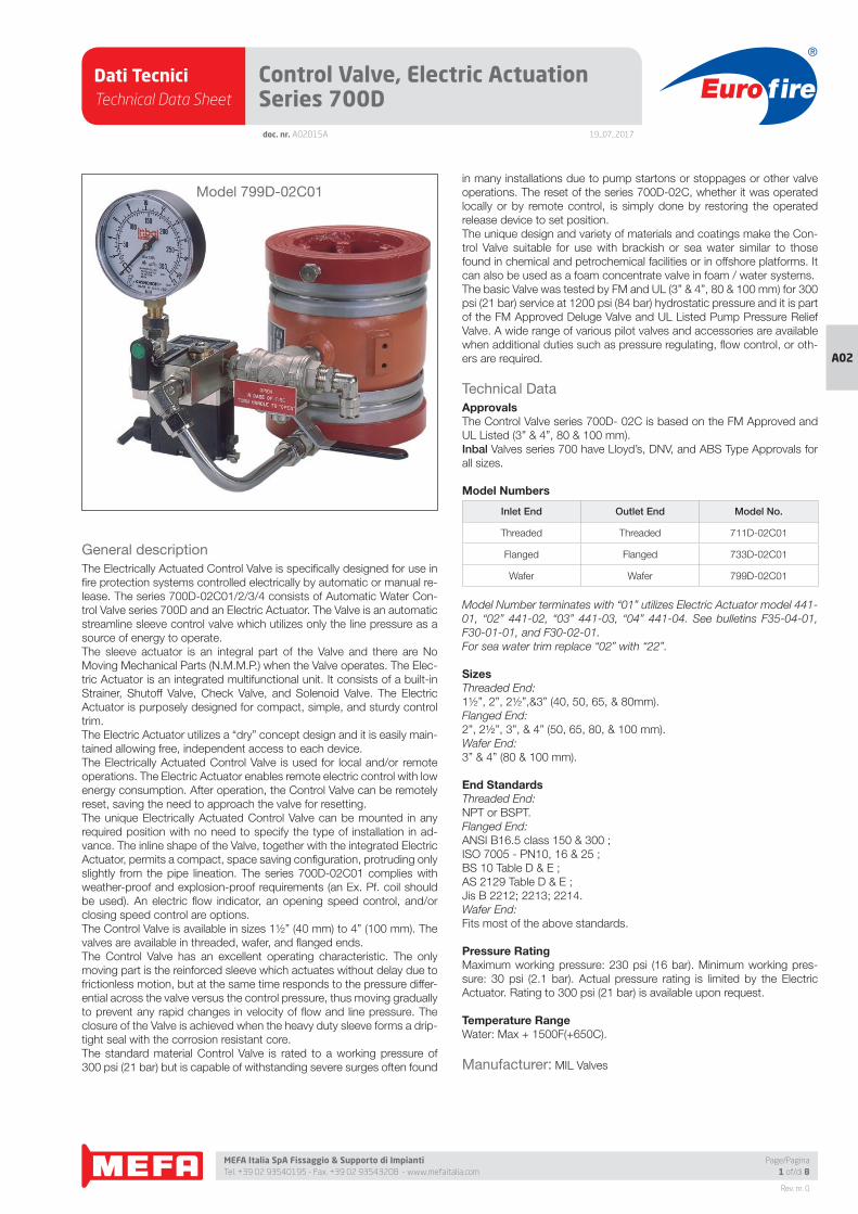
Dati TecniciTechnical Data Sheet
19_07_2017
Euro fire
MEFA Italia SpA Fissaggio & Supporto di Impianti Tel. +39 02 93540195 - Fax. +39 02 93543208 - www.mefaitalia.com
Rev. nr. 0
A02
Page/Pagina1 of/di 8
doc. nr. A02015A
Control Valve, Electric Actuation Series 700D
General description
The Electrically Actuated Control Valve is specifi cally designed for use in
fi re protection systems controlled electrically by automatic or manual re-
lease. The series 700D-02C01/2/3/4 consists of Automatic Water Con-
trol Valve series 700D and an Electric Actuator. The Valve is an automatic
streamline sleeve control valve which utilizes only the line pressure as a
source of energy to operate.
The sleeve actuator is an integral part of the Valve and there are No
Moving Mechanical Parts (N.M.M.P.) when the Valve operates. The Elec-
tric Actuator is an integrated multifunctional unit. It consists of a built-in
Strainer, Shutoff Valve, Check Valve, and Solenoid Valve. The Electric
Actuator is purposely designed for compact, simple, and sturdy control
trim.
The Electric Actuator utilizes a “dry” concept design and it is easily main-
tained allowing free, independent access to each device.
The Electrically Actuated Control Valve is used for local and/or remote
operations. The Electric Actuator enables remote electric control with low
energy consumption. After operation, the Control Valve can be remotely
reset, saving the need to approach the valve for resetting.
The unique Electrically Actuated Control Valve can be mounted in any
required position with no need to specify the type of installation in ad-
vance. The inline shape of the Valve, together with the integrated Electric
Actuator, permits a compact, space saving confi guration, protruding only
slightly from the pipe lineation. The series 700D-02C01 complies with
weather-proof and explosion-proof requirements (an Ex. Pf. coil should
be used). An electric fl ow indicator, an opening speed control, and/or
closing speed control are options.
The Control Valve is available in sizes 1½” (40 mm) to 4” (100 mm). The
valves are available in threaded, wafer, and fl anged ends.
The Control Valve has an excellent operating characteristic. The only
moving part is the reinforced sleeve which actuates without delay due to
frictionless motion, but at the same time responds to the pressure differ-
ential across the valve versus the control pressure, thus moving gradually
to prevent any rapid changes in velocity of fl ow and line pressure. The
closure of the Valve is achieved when the heavy duty sleeve forms a drip-
tight seal with the corrosion resistant core.
The standard material Control Valve is rated to a working pressure of
300 psi (21 bar) but is capable of withstanding severe surges often found
in many installations due to pump startons or stoppages or other valve
operations. The reset of the series 700D-02C, whether it was operated
locally or by remote control, is simply done by restoring the operated
release device to set position.
The unique design and variety of materials and coatings make the Con-
trol Valve suitable for use with brackish or sea water similar to those
found in chemical and petrochemical facilities or in offshore platforms. It
can also be used as a foam concentrate valve in foam / water systems.
The basic Valve was tested by FM and UL (3” & 4”, 80 & 100 mm) for 300
psi (21 bar) service at 1200 psi (84 bar) hydrostatic pressure and it is part
of the FM Approved Deluge Valve and UL Listed Pump Pressure Relief
Valve. A wide range of various pilot valves and accessories are available
when additional duties such as pressure regulating, fl ow control, or oth-
ers are required.
Technical Data
ApprovalsThe Control Valve series 700D- 02C is based on the FM Approved and
UL Listed (3” & 4”, 80 & 100 mm).
Inbal Valves series 700 have Lloyd’s, DNV, and ABS Type Approvals for
all sizes.
Model Numbers
Inlet End Outlet End Model No.
Threaded Threaded 711D-02C01
Flanged Flanged 733D-02C01
Wafer Wafer 799D-02C01
Model Number terminates with “01” utilizes Electric Actuator model 441-
01, “02” 441-02, “03” 441-03, “04” 441-04. See bulletins F35-04-01,
F30-01-01, and F30-02-01.
For sea water trim replace “02” with “22”.
SizesThreaded End:
1½”, 2”, 2½”,&3” (40, 50, 65, & 80mm).
Flanged End:
2”, 2½”, 3”, & 4” (50, 65, 80, & 100 mm).
Wafer End:
3” & 4” (80 & 100 mm).
End StandardsThreaded End:
NPT or BSPT.
Flanged End:
ANSI B16.5 class 150 & 300 ;
ISO 7005 - PN10, 16 & 25 ;
BS 10 Table D & E ;
AS 2129 Table D & E ;
Jis B 2212; 2213; 2214.
Wafer End:
Fits most of the above standards.
Pressure RatingMaximum working pressure: 230 psi (16 bar). Minimum working pres-
sure: 30 psi (2.1 bar). Actual pressure rating is limited by the Electric
Actuator. Rating to 300 psi (21 bar) is available upon request.
Temperature RangeWater: Max + 1500F(+650C).
Manufacturer: MIL Valves
Model 799D-02C01
Dati TecniciTechnical Data Sheet
19_07_2017
Euro fire
MEFA Italia SpA Fissaggio & Supporto di Impianti Tel. +39 02 93540195 - Fax. +39 02 93543208 - www.mefaitalia.com
Rev. nr. 0
A02
doc. nr. A02015A
Control Valve, Electric Actuation Series 700D
Page/Pagina2 of/di 8
Installation PositionAvailable in:
Energized to open , energized to close, and
magnetic latch (impulse) types.
Standard voltages:
AC 50Hz: 24, 48, 110, 220, & 380 volt ; AC
60Hz: 24, 120, & 240 volt ; DC: 12, 24, 48,
110, 120, & 220 volt.
Other voltages are available on request.
Protection type Enclosure:
Conforms to NEMA (1 to 9), IEC (79 & 529), or
CENELEC (50014 to 50019) standards.
See bulletins F30-01-01 and F30-02-01 for
further information.
Installation PositionVertical or horizontal.
MaterialsStandardValve Housing:
Carbon Steel (SAE 1021).
Valve Ends:
Ductile Iron (ASTM A536 65-45-12).
Sleeve:
SMR5 Elastomer reinforced with Polyester and
Kevlar.
Control Trim:
Brass Nickel Chrome plated, Stainless Steel.
OptionalCast Steel ;
Bronze ;
Nickel Aluminium Bronze ;
Stainless Steel AISI 316 ;
Super Austenitic Stainless Steel ;
Super Duplex Stainless Steel ;
Titanium.
CoatingStandardPowder epoxy coated. Thickness: 0.004” (0.1
mm) external and internal surfaces.
OptionalHigh built epoxy coated and polyurethane fi n-
ish. Thickness: 0.01” (0.3 mm).
Halar® coated. Thickness: 0.02” (0.5 mm).
Halar® is a registered trade mark of Ausimont
USA Inc.
Control TrimThe complete control trim includes an Electric
Actuator, Emergency Release Valve, Supply
Pressure Gauge, Pressure Gauge Valve, fi ttings,
and tubing. On standard the control trim is sup-
plied preassembled in sections.
See the applicable Trim Chart for complete
components list.
Features• Any line pressure, either very low or high, is
suffi cient to close the Control Valve and keep
it closed tightly.
• The Valve, designed for control valve service
from basic concepts, utilizes a built-in sleeve
actuator.
• The same control valve can be operated and
reset from the control room as well as from
fi eld contro l panel.
• No Moving Mechanical Parts (N.M.M.P.) con-
struction ensures a long life of dependable
operation, reducing the cost of maintenance.
• Very simple trim, virtually consists of only two
components.
• Integrated multi-function Electric Actuator
(E,A) permits a compact, space saving shape.
• Emergency Release Valve, strainer, shutoff
valve, and check valve are standard devices.
• The Control Valve will not open falsely, not
even slightly or momentarily, due to fl uctua-
tions in the line pressure.
• Quick, yet soft opening performance - elimi-
nates water hammer and consequent dam-
ages.
• Wide range of voltages and enclosure pro-
tections for the Solenoid Valve device in the
Electric Actuator.
• Pressure rating of 230 psi (16 bar) for stand-
ard Control Valve. Rating to 300 psi (21 bar) is
available upon request.
• Wide range of sizes for an ideal system de-
sign.
• Can be installed vertically or horizontally. No
need to specify in advance the type of instal-
lation.
• Control trim made of high grade materials as
standard.
• Epoxy coating supplied as standard - ensures
excellent corrosion resistance.
• Variety of available materials - to ensure cor-
rosion-free service even under severe condi-
tions.
• Ideally suitable for use with brackish and sea
water.
• Complies with weather-proof requirements
as standard. Explosionproof enclosure upon
request.
• High fl ow capabilities due to linear fl ow pat-
tern.
• Opening speed control, closing speed control,
and fl ow indicator are optional.
• Additional functions such as pressure control,
could be added on the same valve body.
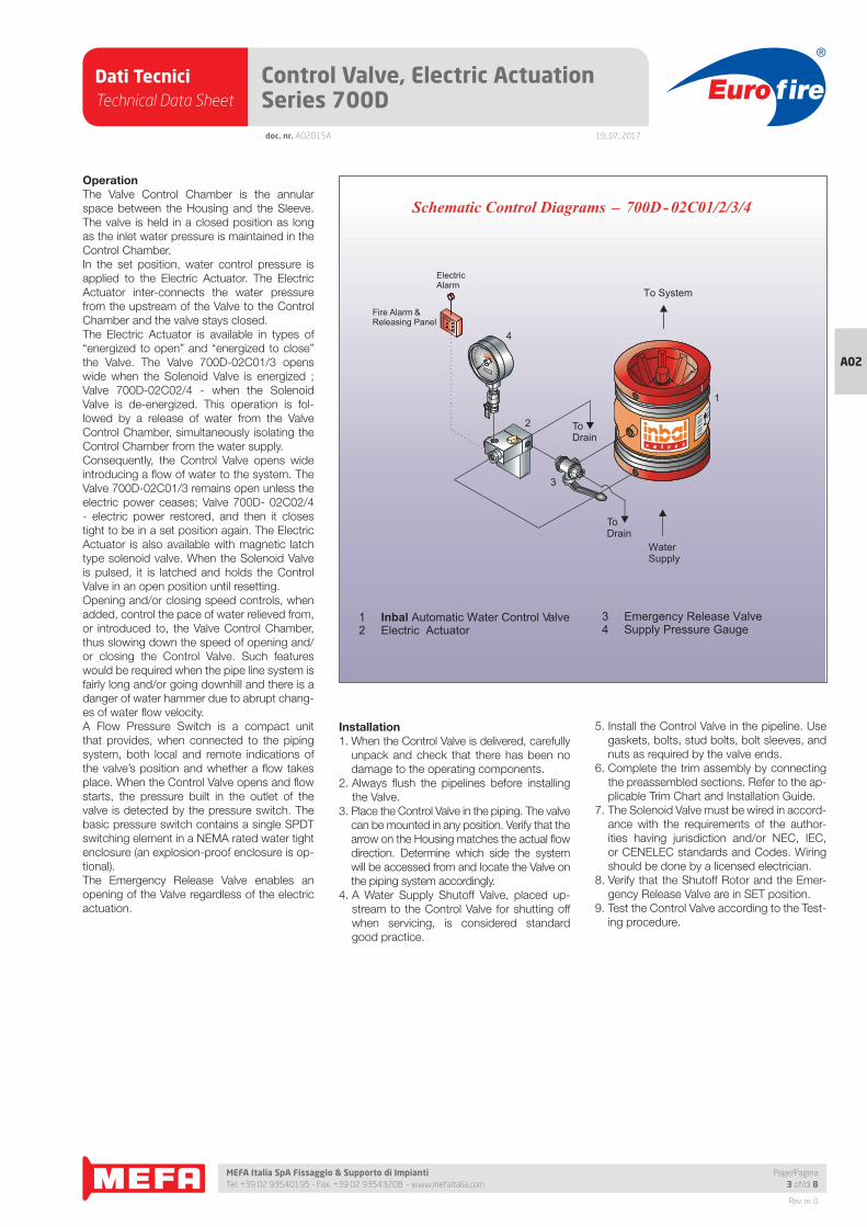
Dati TecniciTechnical Data Sheet
19_07_2017
Euro fire
MEFA Italia SpA Fissaggio & Supporto di Impianti Tel. +39 02 93540195 - Fax. +39 02 93543208 - www.mefaitalia.com
Rev. nr. 0
A02
Page/Pagina3 of/di 8
doc. nr. A02015A
Control Valve, Electric Actuation Series 700D
OperationThe Valve Control Chamber is the annular
space between the Housing and the Sleeve.
The valve is held in a closed position as long
as the inlet water pressure is maintained in the
Control Chamber.
In the set position, water control pressure is
applied to the Electric Actuator. The Electric
Actuator inter-connects the water pressure
from the upstream of the Valve to the Control
Chamber and the valve stays closed.
The Electric Actuator is available in types of
“energized to open” and “energized to close”
the Valve. The Valve 700D-02C01/3 opens
wide when the Solenoid Valve is energized ;
Valve 700D-02C02/4 - when the Solenoid
Valve is de-energized. This operation is fol-
lowed by a release of water from the Valve
Control Chamber, simultaneously isolating the
Control Chamber from the water supply.
Consequently, the Control Valve opens wide
introducing a fl ow of water to the system. The
Valve 700D-02C01/3 remains open unless the
electric power ceases; Valve 700D- 02C02/4
- electric power restored, and then it closes
tight to be in a set position again. The Electric
Actuator is also available with magnetic latch
type solenoid valve. When the Solenoid Valve
is pulsed, it is latched and holds the Control
Valve in an open position until resetting.
Opening and/or closing speed controls, when
added, control the pace of water relieved from,
or introduced to, the Valve Control Chamber,
thus slowing down the speed of opening and/
or closing the Control Valve. Such features
would be required when the pipe line system is
fairly long and/or going downhill and there is a
danger of water hammer due to abrupt chang-
es of water fl ow velocity.
A Flow Pressure Switch is a compact unit
that provides, when connected to the piping
system, both local and remote indications of
the valve’s position and whether a fl ow takes
place. When the Control Valve opens and fl ow
starts, the pressure built in the outlet of the
valve is detected by the pressure switch. The
basic pressure switch contains a single SPDT
switching element in a NEMA rated water tight
enclosure (an explosion-proof enclosure is op-
tional).
The Emergency Release Valve enables an
opening of the Valve regardless of the electric
actuation.
Installation1. When the Control Valve is delivered, carefully
unpack and check that there has been no
damage to the operating components.
2. Always fl ush the pipelines before installing
the Valve.
3. Place the Control Valve in the piping. The valve
can be mounted in any position. Verify that the
arrow on the Housing matches the actual fl ow
direction. Determine which side the system
will be accessed from and locate the Valve on
the piping system accordingly.
4. A Water Supply Shutoff Valve, placed up-
stream to the Control Valve for shutting off
when servicing, is considered standard
good practice.
5. Install the Control Valve in the pipeline. Use
gaskets, bolts, stud bolts, bolt sleeves, and
nuts as required by the valve ends.
6. Complete the trim assembly by connecting
the preassembled sections. Refer to the ap-
plicable Trim Chart and Installation Guide.
7. The Solenoid Valve must be wired in accord-
ance with the requirements of the author-
ities having jurisdiction and/or NEC, IEC,
or CENELEC standards and Codes. Wiring
should be done by a licensed electrician.
8. Verify that the Shutoff Rotor and the Emer-
gency Release Valve are in SET position.
9. Test the Control Valve according to the Test-
ing procedure.
ToDrain
1 Inbal Automatic Water Control Valve2 Electric Actuator
_Schematic Control Diagrams 700D- 02C01/2/3/4
3 Emergency Release Valve 4 Supply Pressure Gauge
WaterSupply
ToDrain
To System
2
3
1
4
ElectricAlarm
Fire Alarm &Releasing Panel
Dati TecniciTechnical Data Sheet
19_07_2017
Euro fire
MEFA Italia SpA Fissaggio & Supporto di Impianti Tel. +39 02 93540195 - Fax. +39 02 93543208 - www.mefaitalia.com
Rev. nr. 0
A02
Page/Pagina4 of/di 8
Control Valve, Electric Actuation Series 700Ddoc. nr. A02015A
ResettingThe Control Valve system must be reset and
restored to service as soon as possible after au-
tomatic, emergency, or manual actuation.
• After electric operation - reset the solenoid
valve (de-energize the “energized to open”
type, energize the “energized to close” type,
or release the “magnetic latch” type). The Con-
trol Valve will close drip tight and the Electric
Alarm is reset. Verify that the supply pressure
has been restored to the normal level.
• After manual emergency operation - restore
the Emergency Release Valve to SET posi-
tion. The Control Valve will close drip tight.
Verify that the supply pressure has been re-
stored to the normal level.
Maintenance, Inspection, & TestingIt is recommended that periodic inspections
and tests be conducted by qualifi ed personnel
to ensure that the Control Valve is in good op-
erating condition. It is recommended that the
Control Valve be tested, operated, cleaned,
and inspected at least on a routine basis.
InspectionA monthly Inspection is recommended:
1. Verify that the Water Supply Shutoff Valve is
sealed in a fully open position.
2. Verify that the Shutoff Valve device in the
Electric Actuator is sealed in a fully open po-
sition (The Shutoff Rotor should be in SET
position).
3. Verify that the Emergency Release Valve is
in SET position.
4. The Pressure Gauge should be checked for
accuracy.
5. Visually inspect for disconnected wires, bro-
ken or missing parts, or other evidence of
impaired protection.
Strainer CleaningA quarterly Strainer Cleaning is recommended:
1. Close the Shutoff Valve device in the Electric
Actuator (Turn the Shutoff Rotor to MAINTE-
NANCE position).
2. Unscrew the Strainer Plug in the Electric Ac-
tuator, remove the screen and clean. Rein-
stall the screen and the plug.
3. Open the Shutoff Valve device in the Electric
Actuator (Return the Shutoff Rotor to SET
position).
Electric Actuation TestingA semi-annual Electric Actuation Testing is rec-
ommended. By performing the Electric Actua-
tion Testing, water will fl ow from all open sprin-
klers and/or nozzles. Prevent damage by taking
the necessary precautions.
1. Operate the Solenoid Valve by energizing
(“energized to open” type), de-energizing
(“energized to close” type), or by “pulsing”
(“magnetic latch” type) the wires leading to
the Solenoid Valve. The Electric Actuator al-
lows the water in the Valve Control Chamber
to exhaust to the atmosphere. The Electric
Alarm should operate and the Control Valve
opens and water will fl ow to the system. Ver-
ify that the whole system is working properly.
2. Reset the Solenoid Valve by deenergizing
(“energized to open” type), by energizing
(“energized to close” type), or by “pulsing”
(“magnetic latch” type) the wires leading to
the Solenoid Valve. The Electric Actuator
interconnects the Valve inlet pressure with
the Control Chamber. Verify that the Control
Valve closes drip tight and the Electric Alarm
is reset.
Emergency Release TestingAn annual Emergency Release Testing is rec-
ommended. By performing the Emergency
Release Testing, water will fl ow from all open
sprinklers and/or nozzles. Prevent damage by
taking the necessary precautions.
1. Turn the Emergency Release Valve handle
to OPEN position to allow the water in the
Valve Control Chamber to exhaust out of the
Vent Port of the Emergency Release Valve to
the atmosphere. After a trickle of water is re-
lieved, the exhausted fl ow should stop. The
Control Valve opens wide and water will fl ow
to the system. Verify that the whole system
is working properly.
2. Return the Emergency Release Valve handle
to SET position to introduce water from the
Valve inlet to the Control Chamber. Verify that
the Control Valve closes drip tight.
RemovalTo remove the Inba l Contro l Valve:
1. Close all the pressure supply valves:
a) Water Supply Shutoff Valve.
b) Shutoff Valve device in the Electric Actua-
tor.
2. Open the Emergency Release Valve to re-
lease the water pressure from the Valve
Control Chamber.
3. Disconnect the electric wires from the sole-
noid coil. The electric work should be done
by a licensed electrician.
4. Remove the Control Valve from the line for
inspection.
5. To reinstall, follow the Installation procedure
(use new gaskets for fl anged or wafer valve).
Inquiries/Orders
The Data Sheet For Inquiries/Orders (bulletin
F01-05-01) should be submitted.
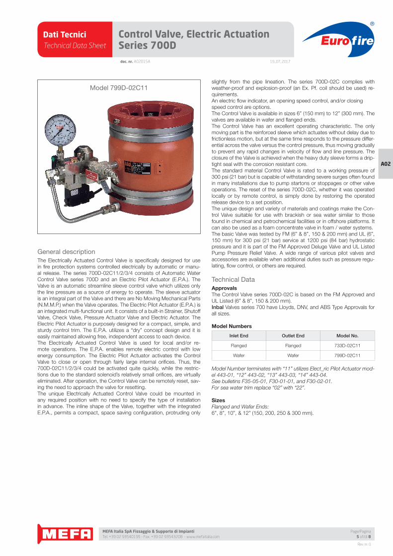
Dati TecniciTechnical Data Sheet
19_07_2017
Euro fire
MEFA Italia SpA Fissaggio & Supporto di Impianti Tel. +39 02 93540195 - Fax. +39 02 93543208 - www.mefaitalia.com
Rev. nr. 0
A02
Page/Pagina5 of/di 8
Control Valve, Electric Actuation Series 700Ddoc. nr. A02015A
General description
The Electrically Actuated Control Valve is specifi cally designed for use
in fi re protection systems controlled electrically by automatic or manu-
al release. The series 700D-02C11/2/3/4 consists of Automatic Water
Control Valve series 700D and an Electric Pilot Actuator (E.P.A.). The
Valve is an automatic streamline sleeve control valve which utilizes only
the line pressure as a source of energy to operate. The sleeve actuator
is an integral part of the Valve and there are No Moving Mechanical Parts
(N.M.M.P.) when the Valve operates. The Electric Pilot Actuator (E.P.A.) is
an integrated multi-functional unit. It consists of a built-in Strainer, Shutoff
Valve, Check Valve, Pressure Actuator Valve and Electric Actuator. The
Electric Pilot Actuator is purposely designed for a compact, simple, and
sturdy control trim. The E.P.A. utilizes a “dry” concept design and it is
easily maintained allowing free, independent access to each device.
The Electrically Actuated Control Valve is used for local and/or re-
mote operations. The E.P.A. enables remote electric control with low
energy consumption. The Electric Pilot Actuator activates the Control
Valve to close or open through fairly large internal orifi ces. Thus, the
700D-02C11/2/3/4 could be activated quite quickly, while the restric-
tions due to the standard solenoid’s relatively small orifi ces, are virtually
eliminated. After operation, the Control Valve can be remotely reset, sav-
ing the need to approach the valve for resetting.
The unique Electrically Actuated Control Valve could be mounted in
any required position with no need to specify the type of installation
in advance. The inline shape of the Valve, together with the integrated
E.P.A., permits a compact, space saving confi guration, protruding only
slightly from the pipe lineation. The series 700D-02C complies with
weather-proof and explosion-proof (an Ex. Pf. coil should be used) re-
quirements.
An electric fl ow indicator, an opening speed control, and/or closing
speed control are options.
The Control Valve is available in sizes 6” (150 mm) to 12” (300 mm). The
valves are available in wafer and fl anged ends.
The Control Valve has an excellent operating characteristic. The only
moving part is the reinforced sleeve which actuates without delay due to
frictionless motion, but at the same time responds to the pressure differ-
ential across the valve versus the control pressure, thus moving gradually
to prevent any rapid changes in velocity of fl ow and line pressure. The
closure of the Valve is achieved when the heavy duty sleeve forms a drip-
tight seal with the corrosion resistant core.
The standard material Control Valve is rated to a working pressure of
300 psi (21 bar) but is capable of withstanding severe surges often found
in many installations due to pump startons or stoppages or other valve
operations. The reset of the series 700D-02C, whether it was operated
locally or by remote control, is simply done by restoring the operated
release device to a set position.
The unique design and variety of materials and coatings make the Con-
trol Valve suitable for use with brackish or sea water similar to those
found in chemical and petrochemical facilities or in offshore platforms. It
can also be used as a foam concentrate valve in foam / water systems.
The basic Valve was tested by FM (6” & 8”, 150 & 200 mm) and UL (6”,
150 mm) for 300 psi (21 bar) service at 1200 psi (84 bar) hydrostatic
pressure and it is part of the FM Approved Deluge Valve and UL Listed
Pump Pressure Relief Valve. A wide range of various pilot valves and
accessories are available when additional duties such as pressure regu-
lating, fl ow control, or others are required.
Technical Data
ApprovalsThe Control Valve series 700D-02C is based on the FM Approved and
UL Listed (6” & 8”, 150 & 200 mm).
Inbal Valves series 700 have Lloyds, DNV, and ABS Type Approvals for
all sizes.
Model Numbers
Inlet End Outlet End Model No.
Flanged Flanged 733D-02C11
Wafer Wafer 799D-02C11
Model Number terminates with “11” utilizes Elect_ric Pilot Actuator mod-
el 443-01, “12” 443-02, “13” 443-03, “14” 443-04.
See bulletins F35-05-01, F30-01-01, and F30-02-01.
For sea water trim replace “02” with “22”.
SizesFlanged and Wafer Ends:
6”, 8”, 10”, & 12” (150, 200, 250 & 300 mm).
Model 799D-02C11
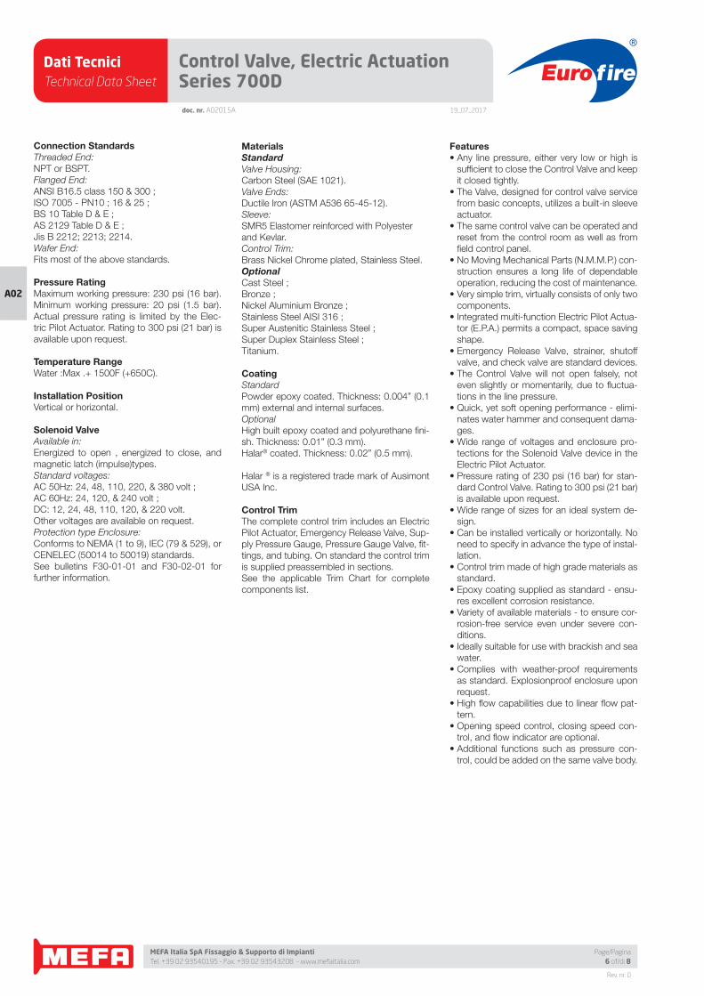
Dati TecniciTechnical Data Sheet
19_07_2017
Euro fire
MEFA Italia SpA Fissaggio & Supporto di Impianti Tel. +39 02 93540195 - Fax. +39 02 93543208 - www.mefaitalia.com
Rev. nr. 0
A02
Page/Pagina6 of/di 8
Control Valve, Electric Actuation Series 700Ddoc. nr. A02015A
Connection StandardsThreaded End:
NPT or BSPT.
Flanged End:
ANSI B16.5 class 150 & 300 ;
ISO 7005 - PN10 ; 16 & 25 ;
BS 10 Table D & E ;
AS 2129 Table D & E ;
Jis B 2212; 2213; 2214.
Wafer End:
Fits most of the above standards.
Pressure RatingMaximum working pressure: 230 psi (16 bar).
Minimum working pressure: 20 psi (1.5 bar).
Actual pressure rating is limited by the Elec-
tric Pilot Actuator. Rating to 300 psi (21 bar) is
available upon request.
Temperature RangeWater :Max .+ 1500F (+650C).
Installation PositionVertical or horizontal.
Solenoid ValveAvailable in:
Energized to open , energized to close, and
magnetic latch (impulse)types.
Standard voltages:
AC 50Hz: 24, 48, 110, 220, & 380 volt ;
AC 60Hz: 24, 120, & 240 volt ;
DC: 12, 24, 48, 110, 120, & 220 volt.
Other voltages are available on request.
Protection type Enclosure:
Conforms to NEMA (1 to 9), IEC (79 & 529), or
CENELEC (50014 to 50019) standards.
See bulletins F30-01-01 and F30-02-01 for
further information.
MaterialsStandardValve Housing:
Carbon Steel (SAE 1021).
Valve Ends:
Ductile Iron (ASTM A536 65-45-12).
Sleeve:
SMR5 Elastomer reinforced with Polyester
and Kevlar.
Control Trim:
Brass Nickel Chrome plated, Stainless Steel.
OptionalCast Steel ;
Bronze ;
Nickel Aluminium Bronze ;
Stainless Steel AISI 316 ;
Super Austenitic Stainless Steel ;
Super Duplex Stainless Steel ;
Titanium.
CoatingStandard
Powder epoxy coated. Thickness: 0.004” (0.1
mm) external and internal surfaces.
Optional
High built epoxy coated and polyurethane fi ni-
sh. Thickness: 0.01” (0.3 mm).
Halar® coated. Thickness: 0.02” (0.5 mm).
Halar ® is a registered trade mark of Ausimont
USA Inc.
Control TrimThe complete control trim includes an Electric
Pilot Actuator, Emergency Release Valve, Sup-
ply Pressure Gauge, Pressure Gauge Valve, fi t-
tings, and tubing. On standard the control trim
is supplied preassembled in sections.
See the applicable Trim Chart for complete
components list.
Features• Any line pressure, either very low or high is
suffi cient to close the Control Valve and keep
it closed tightly.
• The Valve, designed for control valve service
from basic concepts, utilizes a built-in sleeve
actuator.
• The same control valve can be operated and
reset from the control room as well as from
fi eld control panel.
• No Moving Mechanical Parts (N.M.M.P.) con-
struction ensures a long life of dependable
operation, reducing the cost of maintenance.
• Very simple trim, virtually consists of only two
components.
• Integrated multi-function Electric Pilot Actua-
tor (E.P.A.) permits a compact, space saving
shape.
• Emergency Release Valve, strainer, shutoff
valve, and check valve are standard devices.
• The Control Valve will not open falsely, not
even slightly or momentarily, due to fl uctua-
tions in the line pressure.
• Quick, yet soft opening performance - elimi-
nates water hammer and consequent dama-
ges.
• Wide range of voltages and enclosure pro-
tections for the Solenoid Valve device in the
Electric Pilot Actuator.
• Pressure rating of 230 psi (16 bar) for stan-
dard Control Valve. Rating to 300 psi (21 bar)
is available upon request.
• Wide range of sizes for an ideal system de-
sign.
• Can be installed vertically or horizontally. No
need to specify in advance the type of instal-
lation.
• Control trim made of high grade materials as
standard.
• Epoxy coating supplied as standard - ensu-
res excellent corrosion resistance.
• Variety of available materials - to ensure cor-
rosion-free service even under severe con-
ditions.
• Ideally suitable for use with brackish and sea
water.
• Complies with weather-proof requirements
as standard. Explosionproof enclosure upon
request.
• High fl ow capabilities due to linear fl ow pat-
tern.
• Opening speed control, closing speed con-
trol, and fl ow indicator are optional.
• Additional functions such as pressure con-
trol, could be added on the same valve body.
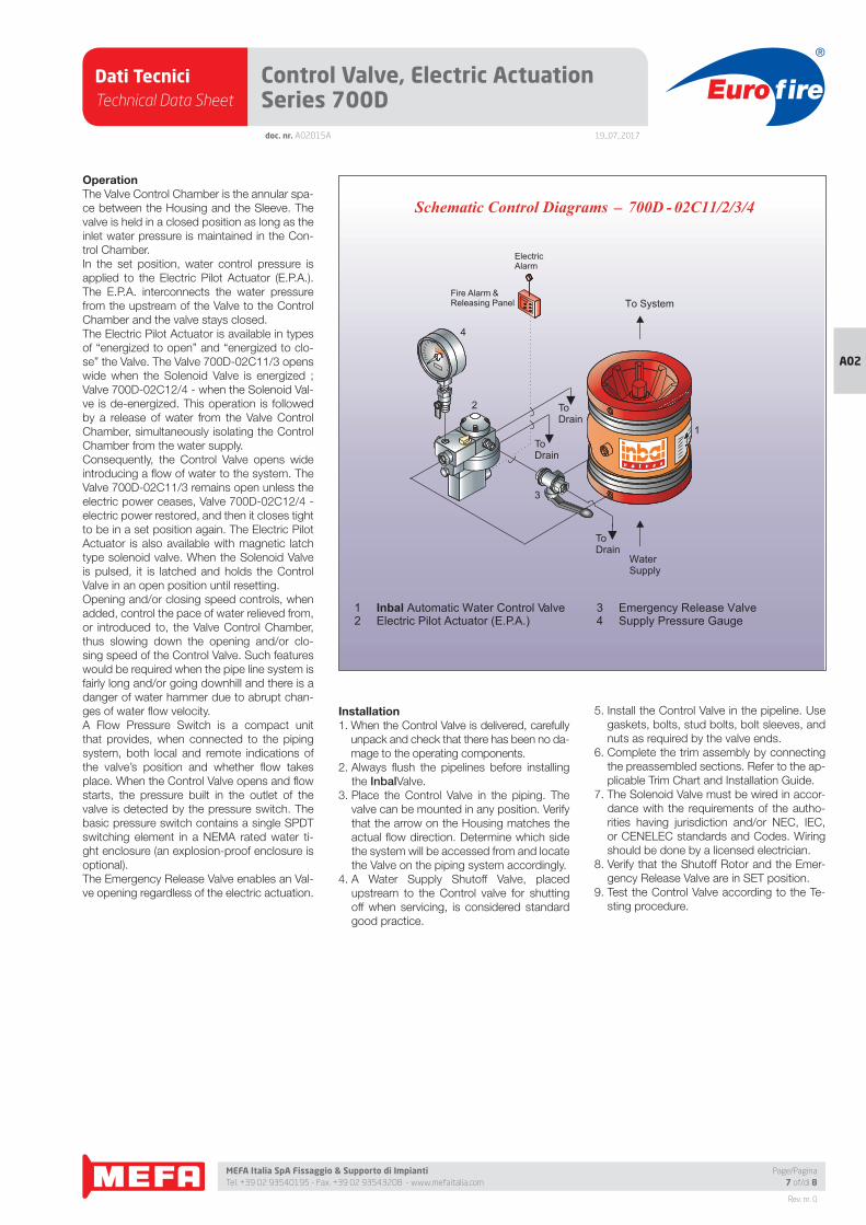
Dati TecniciTechnical Data Sheet
19_07_2017
Euro fire
MEFA Italia SpA Fissaggio & Supporto di Impianti Tel. +39 02 93540195 - Fax. +39 02 93543208 - www.mefaitalia.com
Rev. nr. 0
A02
Page/Pagina7 of/di 8
doc. nr. A02015A
Control Valve, Electric Actuation Series 700D
OperationThe Valve Control Chamber is the annular spa-
ce between the Housing and the Sleeve. The
valve is held in a closed position as long as the
inlet water pressure is maintained in the Con-
trol Chamber.
In the set position, water control pressure is
applied to the Electric Pilot Actuator (E.P.A.).
The E.P.A. interconnects the water pressure
from the upstream of the Valve to the Control
Chamber and the valve stays closed.
The Electric Pilot Actuator is available in types
of “energized to open” and “energized to clo-
se” the Valve. The Valve 700D-02C11/3 opens
wide when the Solenoid Valve is energized ;
Valve 700D-02C12/4 - when the Solenoid Val-
ve is de-energized. This operation is followed
by a release of water from the Valve Control
Chamber, simultaneously isolating the Control
Chamber from the water supply.
Consequently, the Control Valve opens wide
introducing a fl ow of water to the system. The
Valve 700D-02C11/3 remains open unless the
electric power ceases, Valve 700D-02C12/4 -
electric power restored, and then it closes tight
to be in a set position again. The Electric Pilot
Actuator is also available with magnetic latch
type solenoid valve. When the Solenoid Valve
is pulsed, it is latched and holds the Control
Valve in an open position until resetting.
Opening and/or closing speed controls, when
added, control the pace of water relieved from,
or introduced to, the Valve Control Chamber,
thus slowing down the opening and/or clo-
sing speed of the Control Valve. Such features
would be required when the pipe line system is
fairly long and/or going downhill and there is a
danger of water hammer due to abrupt chan-
ges of water fl ow velocity.
A Flow Pressure Switch is a compact unit
that provides, when connected to the piping
system, both local and remote indications of
the valve’s position and whether fl ow takes
place. When the Control Valve opens and fl ow
starts, the pressure built in the outlet of the
valve is detected by the pressure switch. The
basic pressure switch contains a single SPDT
switching element in a NEMA rated water ti-
ght enclosure (an explosion-proof enclosure is
optional).
The Emergency Release Valve enables an Val-
ve opening regardless of the electric actuation.
Installation1. When the Control Valve is delivered, carefully
unpack and check that there has been no da-
mage to the operating components.
2. Always fl ush the pipelines before installing
the InbalValve.
3. Place the Control Valve in the piping. The
valve can be mounted in any position. Verify
that the arrow on the Housing matches the
actual fl ow direction. Determine which side
the system will be accessed from and locate
the Valve on the piping system accordingly.
4. A Water Supply Shutoff Valve, placed
upstream to the Control valve for shutting
off when servicing, is considered standard
good practice.
5. Install the Control Valve in the pipeline. Use
gaskets, bolts, stud bolts, bolt sleeves, and
nuts as required by the valve ends.
6. Complete the trim assembly by connecting
the preassembled sections. Refer to the ap-
plicable Trim Chart and Installation Guide.
7. The Solenoid Valve must be wired in accor-
dance with the requirements of the autho-
rities having jurisdiction and/or NEC, IEC,
or CENELEC standards and Codes. Wiring
should be done by a licensed electrician.
8. Verify that the Shutoff Rotor and the Emer-
gency Release Valve are in SET position.
9. Test the Control Valve according to the Te-
sting procedure.
ToDrain
ToDrain
_Schematic Control Diagrams 700D - 02C11/2/3/4
3
2
4
1 Inbal Automatic Water Control Valve2 Electric Pilot Actuator (E.P.A.)
ElectricAlarm
Fire Alarm &Releasing Panel
ToDrain
WaterSupply
To System
1
3 Emergency Release Valve 4 Supply Pressure Gauge
Dati TecniciTechnical Data Sheet
19_07_2017
Euro fire
MEFA Italia SpA Fissaggio & Supporto di Impianti Tel. +39 02 93540195 - Fax. +39 02 93543208 - www.mefaitalia.com
NOTA GENERALE:
L’attrezzatura presentata in questo bollettino deve essere installata in conformità agli ultimi standard pubblicati dalle Norme UNI EN 12845, National Fire Protection Association, Factory Mutual Research Corporation o altre organizzazioni simili e anche con le disposizioni dei codici governativi o delle ordinanze laddove applicabili.Con la presente pagina tecnica, MEFA Italia intende fornire pertinenti informazioni tecniche, aggiornandole periodicamente.MEFA Italia non si ritiene responsabile in caso di errori di stampa o informazioni inesatte in quanto le stesse possono variare senza preavviso.
The equipment presented in this bulletin is to be installed in accordance with the latest published Standards of the UNI EN 12845, National Fire Protection Association, Factory Mutual Research Corporation, or other similar organizations and also with the provisions of governmental codes or ordinances whenever applicable.With this technical page, MEFA Italia intends to provide relevant technical information, updating them periodically.MEFA Italia is not responsible for any inaccurate print or inaccurate information as these may vary without prior notice.
NOTA EUROFIRE:
Eurofi re è un marchio registrato da MEFA Italia per la presentazione di tutti i prodotti della linea Antincendio.I fornitori dei prodotti Eurofi re vengono rigorosamente selezionati nel rispetto della qualità e delle caratteristiche distintive descrittte in questo documento tecnico.I fornitori dei prodotti potrebbero variare senza preavviso, ma sempre nel rispetto delle caratteristiche qui descritte.
Eurofi re is a registered trademark of MEFA Italia for the presentation of all products of the Fire Protection Line.The suppliers of Eurofi re products are strictly selected in compliance with the quality and distinctive features described in this technical document.Product providers may vary without notice, but always respecting the features described herein.
Rev. nr. 0
A02
Page/Pagina8 of/di 8
doc. nr. A02015A
Control Valve, Electric Actuation Series 700D
ResettingThe Control Valve system must be reset and
restored to service as soon as possible after au-
tomatic, emergency, or manual actuation:
! After electric operation - reset the solenoid
valve (de-energize the “energized to open”
type, energize the “energized to close” type, or
release the “magnetic latch” type). The Control
Valve will close drip tight and the Electric Alarm
is reset. Verify that the supply pressure has
been restored to the normal level.
! After manual emergency operation - restore
the Emergency Release Valve to SET position.
The Control Valve will close drip tight. Verify that
the supply pressure has been restored to the
normal level.
Maintenance, Inspection, & TestingIt is recommended that periodic inspections
and tests be conducted by qualifi ed personnel
to ensure that the Control Valve is in good op-
erating condition. It is recommended that the
Control Valve be tested, operated, cleaned,
and inspected at least on a routine basis.
InspectionA monthly Inspection is recommended:
1. Verify that the Water Supply Valve is sealed
in a fully open position.
2. Verify that the Shutoff Valve device in the
E.P.A. is sealed in a fully open position (The
Shutoff Rotor should be in SET position).
3. Verify that the Emergency Release Valve is
in SET position.
4. The Pressure Gauge should be checked for
accuracy.
5. Visually inspect for disconnected wires, bro-
ken or missing parts, or other evidence of
impaired protection.
Strainer CleaningA quarterly Strainer Cleaning is recommended:
1. Close the Shutoff Valve device in the E.P.A.
(Turn the Shutoff Rotor to MAINTENANCE
position).
2. Unscrew the Strainer Plug in the E.P.A.,
remove the screen and clean. Reinstall the
screen and the plug.
3. Open the Shutoff Valve device in the E.P.A.
(Return the Shutoff Rotor to SET position).
WARNING: The shutoff Rotor must be in
SET position, otherwise proper operation of
the valve will be interrupted.
Electric Actuation TestingA semi-annual Electric Actuation Testing is rec-
ommended. By performing the Electric Actua-
tion Testing, water will fl ow from all open sprin-
klers and/or nozzles Prevent damage by taking
the necessary precautions.
1. Operate the solenoid valve by energizing
(“energized to open” type), de-energizing
(“energized to close” type), or by “pulsing”
(“magnetic latch” type) the wires leading to
the solenoid valve. The E.P.A. allows the
water in the Valve Control Chamber to ex-
haust to the atmosphere. The Control Valve
opens and water will fl ow to the system. The
Electric Alarm should operate. Verify that the
whole system is working properly.
2. Reset the solenoid valve by deenergizing
(“energized to open” type), by energizing
(“energized to close” type), or by “pulsing”
(“magnetic latch” type) the wires leading to
the solenoid valve. The E.P.A. interconnects
the Valve inlet pressure with the Control
Chamber. Verify that the Control Valve clos-
es drip tight and the Electric Alarm is reset.
Emergency Release TestingAn annual Emergency Release Testing is rec-
ommended. By performing the Emergency
Release Testing, water will fl ow from all open
sprinklers and/or nozzles. Prevent damage by
taking the necessary precautions.
1. Turn the Emergency Release Valve handle
to OPEN position, to allow the water in the
Valve Control Chamber to exhaust out of the
Vent Port of the Emergency Release Valve
to the atmosphere. After a trickle of water
is relieved, the exhausted fl ow should stop.
The Electric Alarm should operate and the
Control Valve opens wide and water will fl ow
to the system. Verify that the whole system
is working properly.
2. Return the Emergency Release Valve handle
to SET position to introduce water from the
Valve inlet to the Control Chamber. Verify that
the Control Valve closes drip tight.
RemovalTo remove the Control Valve:
1. Close all the pressure supply valves:
a) Water Supply Shutoff Valve .
b) Shutoff Valve device in the E.P.A.
2. Open the Emergency Release Valve to re-
lease the water pressure from the Inbal-Valve Control Chamber.
3. Disconnect the electric wires from the sole-
noid coil. The electric work should be done
by a licensed electrician.
4. Remove the Control Valve from the line for
inspection.
5. To reinstall, follow the Installation procedure
(use new gaskets for fl anged or wafer valve).
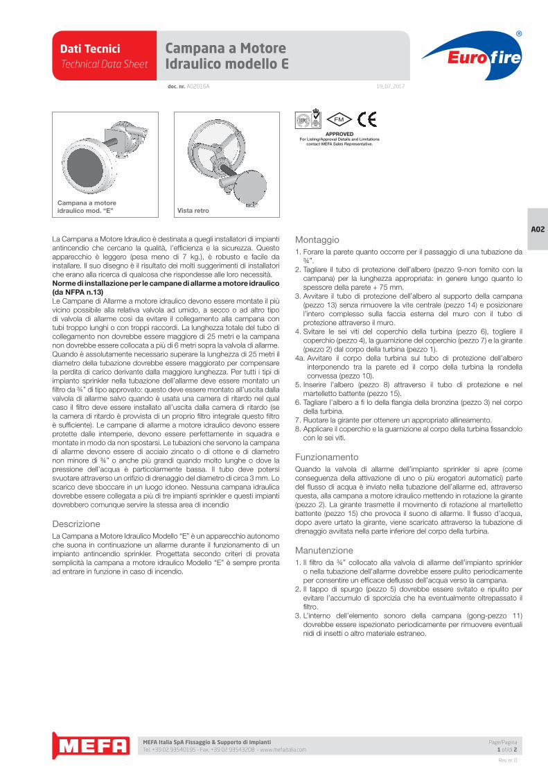
Dati TecniciTechnical Data Sheet
19_07_2017
Euro fire
MEFA Italia SpA Fissaggio & Supporto di Impianti Tel. +39 02 93540195 - Fax. +39 02 93543208 - www.mefaitalia.com
Rev. nr. 0
A02
doc. nr. A02016A
Campana a Motore Idraulico modello E
APPROVED For Listing/Approval Details and Limitations
contact MEFA Sales Representative.
Campana a motore idraulico mod. “E” Vista retro
Page/Pagina1 of/di 2
La Campana a Motore Idraulico è destinata a quegli installatori di impianti
antincendio che cercano la qualità, l’effi cienza e la sicurezza. Questo
apparecchio è leggero (pesa meno di 7 kg.), è robusto e facile da
installare. Il suo disegno è il risultato dei molti suggerimenti di installatori
che erano alla ricerca di qualcosa che rispondesse alle loro necessità.
Norme di installazione per le campane di allarme a motore idraulico (da NFPA n.13) Le Campane di Allarme a motore idraulico devono essere montate il più
vicino possibile alla relativa valvola ad umido, a secco o ad altro tipo
di valvola di allarme così da evitare il collegamento alla campana con
tubi troppo lunghi o con troppi raccordi. La lunghezza totale del tubo di
collegamento non dovrebbe essere maggiore di 25 metri e la campana
non dovrebbe essere collocata a più di 6 metri sopra la valvola di allarme.
Quando è assolutamente necessario superare la lunghezza di 25 metri il
diametro della tubazione dovrebbe essere maggiorato per compensare
la perdita di carico derivante dalla maggiore lunghezza. Per tutti i tipi di
impianto sprinkler nella tubazione dell’allarme deve essere montato un
fi ltro da ¾” di tipo approvato: questo deve essere montato all’uscita dalla
valvola di allarme salvo quando è usata una camera di ritardo nel qual
caso il fi ltro deve essere installato all’uscita dalla camera di ritardo (se
la camera di ritardo è provvista di un proprio fi ltro integrale questo fi ltro
è suffi ciente). Le campane di allarme a motore idraulico devono essere
protette dalle intemperie, devono essere perfettamente in squadra e
montate in modo da non spostarsi. Le tubazioni che servono la campana
di allarme devono essere di acciaio zincato o di ottone e di diametro
non minore di ¾” o anche più grandi quando molto lunghe o dove la
pressione dell’acqua è particolarmente bassa. Il tubo deve potersi
svuotare attraverso un orifi zio di drenaggio del diametro di circa 3 mm. Lo
scarico deve sboccare in un luogo idoneo. Nessuna campana idraulica
dovrebbe essere collegata a più di tre impianti sprinkler e questi impianti
dovrebbero comunque servire la stessa area di incendio
Descrizione
La Campana a Motore Idraulico Modello “E” è un apparecchio autonomo
che suona in continuazione un allarme durante il funzionamento di un
impianto antincendio sprinkler. Progettata secondo criteri di provata
semplicità la campana a motore idraulico Modello “E” è sempre pronta
ad entrare in funzione in caso di incendio.
Montaggio
1. Forare la parete quanto occorre per il passaggio di una tubazione da
¾”.
2. Tagliare il tubo di protezione dell’albero (pezzo 9-non fornito con la
campana) per la lunghezza appropriata: in genere lungo quanto lo
spessore della parete + 75 mm.
3. Avvitare il tubo di protezione dell’albero al supporto della campana
(pezzo 13) senza rimuovere la vite centrale (pezzo 14) e posizionare
l’intero complesso sulla faccia esterna del muro con il tubo di
protezione attraverso il muro.
4. Svitare le sei viti del coperchio della turbina (pezzo 6), togliere il
coperchio (pezzo 4), la guarnizione del coperchio (pezzo 7) e la girante
(pezzo 2) dal corpo della turbina (pezzo 1).
4a. Avvitare il corpo della turbina sul tubo di protezione dell’albero
interponendo tra la parete ed il corpo della turbina la rondella
convessa (pezzo 10).
5. Inserire l’albero (pezzo 8) attraverso il tubo di protezione e nel
martelletto battente (pezzo 15).
6. Tagliare l’albero a fi lo della fl angia della bronzina (pezzo 3) nel corpo
della turbina.
7. Ruotare la girante per ottenere un appropriato allineamento.
8. Applicare il coperchio e la guarnizione al corpo della turbina fi ssandolo
con le sei viti.
Funzionamento
Quando la valvola di allarme dell’impianto sprinkler si apre (come
conseguenza della attivazione di uno o più erogatori automatici) parte
del fl usso di acqua è inviato nella tubazione dell’allarme ed, attraverso
questa, alla campana a motore idraulico mettendo in rotazione la girante
(pezzo 2). La girante trasmette il movimento di rotazione al martelletto
battente (pezzo 15) che provoca il suono di allarme. Il fl usso d’acqua,
dopo avere urtato la girante, viene scaricato attraverso la tubazione di
drenaggio avvitata nella parte inferiore del corpo della turbina.
Manutenzione
1. Il fi ltro da ¾” collocato alla valvola di allarme dell’impianto sprinkler
o nella tubazione dell’allarme dovrebbe essere pulito periodicamente
per consentire un effi cace defl usso dell’acqua verso la campana.
2. Il tappo di spurgo (pezzo 5) dovrebbe essere svitato e ripulito per
evitare l’accumulo di sporcizia che ha eventualmente oltrepassato il
fi ltro.
3. L’interno dell’elemento sonoro della campana (gong-pezzo 11)
dovrebbe essere ispezionato periodicamente per rimuovere eventuali
nidi di insetti o altro materiale estraneo.
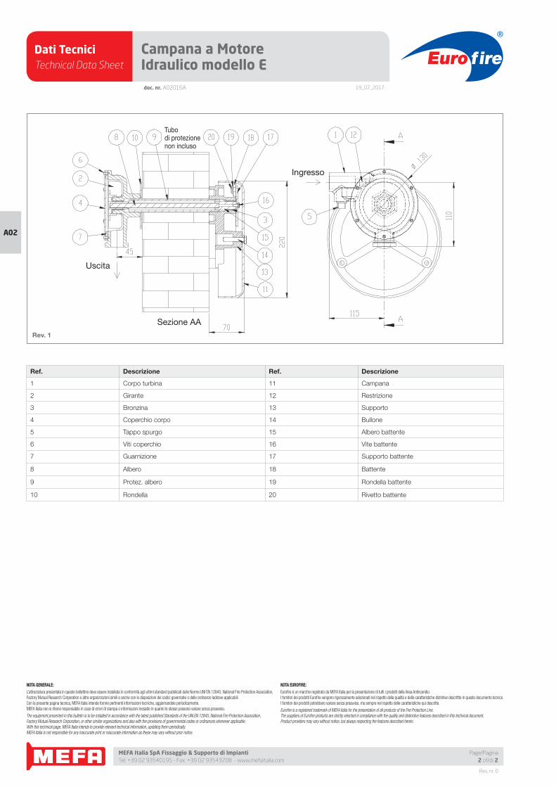
Dati TecniciTechnical Data Sheet
19_07_2017
Euro fire
MEFA Italia SpA Fissaggio & Supporto di Impianti Tel. +39 02 93540195 - Fax. +39 02 93543208 - www.mefaitalia.com
Rev. nr. 0
A02
NOTA EUROFIRE:
Eurofi re è un marchio registrato da MEFA Italia per la presentazione di tutti i prodotti della linea Antincendio.I fornitori dei prodotti Eurofi re vengono rigorosamente selezionati nel rispetto della qualità e delle caratteristiche distintive descrittte in questo documento tecnico.I fornitori dei prodotti potrebbero variare senza preavviso, ma sempre nel rispetto delle caratteristiche qui descritte.
Eurofi re is a registered trademark of MEFA Italia for the presentation of all products of the Fire Protection Line.The suppliers of Eurofi re products are strictly selected in compliance with the quality and distinctive features described in this technical document.Product providers may vary without notice, but always respecting the features described herein.
NOTA GENERALE:
L’attrezzatura presentata in questo bollettino deve essere installata in conformità agli ultimi standard pubblicati dalle Norme UNI EN 12845, National Fire Protection Association, Factory Mutual Research Corporation o altre organizzazioni simili e anche con le disposizioni dei codici governativi o delle ordinanze laddove applicabili.Con la presente pagina tecnica, MEFA Italia intende fornire pertinenti informazioni tecniche, aggiornandole periodicamente.MEFA Italia non si ritiene responsabile in caso di errori di stampa o informazioni inesatte in quanto le stesse possono variare senza preavviso.
The equipment presented in this bulletin is to be installed in accordance with the latest published Standards of the UNI EN 12845, National Fire Protection Association, Factory Mutual Research Corporation, or other similar organizations and also with the provisions of governmental codes or ordinances whenever applicable.With this technical page, MEFA Italia intends to provide relevant technical information, updating them periodically.MEFA Italia is not responsible for any inaccurate print or inaccurate information as these may vary without prior notice.
Page/Pagina2 of/di 2
doc. nr. A02016A
Campana a Motore Idraulico modello E
Rev. 1
Uscita
Sezione AA
Ingresso
Tubodi protezionenon incluso
Ref. Descrizione Ref. Descrizione
1 Corpo turbina 11 Campana
2 Girante 12 Restrizione
3 Bronzina 13 Supporto
4 Coperchio corpo 14 Bullone
5 Tappo spurgo 15 Albero battente
6 Viti coperchio 16 Vite battente
7 Guarnizione 17 Supporto battente
8 Albero 18 Battente
9 Protez. albero 19 Rondella battente
10 Rondella 20 Rivetto battente
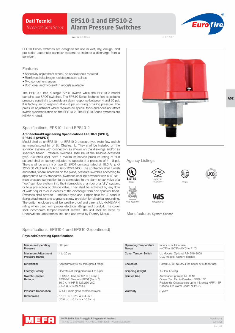
Dati TecniciTechnical Data Sheet
19_07_2017
Euro fire
MEFA Italia SpA Fissaggio & Supporto di Impianti Tel. +39 02 93540195 - Fax. +39 02 93543208 - www.mefaitalia.com
Rev. nr. 0
A02
Page/Pagina1 of/di 2
doc. nr. A02017A
EPS10-1 and EPS10-2 Alarm Pressure Switches
EPS10 Series switches are designed for use in wet, dry, deluge, and
pre-action automatic sprinkler systems to indicate a discharge from a
sprinkler.
Features
• Sensitivity adjustment wheel, no special tools required
• Reinforced diaphragm resists pressure spikes
• Two conduit entrances
• Both one- and two-switch models available
The EPS10-1 has a single SPDT switch while the EPS10-2 model
contains two SPDT switches. The EPS10 Series features fi eld adjustable
pressure sensitivity to provide an alarm response between 4 and 20 psi.
It is factory set to respond at 4 – 8 psi on rising or falling pressure. The
pressure adjustment wheel requires no special tools and does not affect
switch synchronization on the EPS10-2. The EPS10 Series switches are
NEMA 4 rated.
Specifi cations, EPS10-1 and EPS10-2
Architectural/Engineering Specifi cations EPS10-1 (SPDT), EPS10-2 (2/SPDT)Model shall be an EPS10-1 or EPS10-2 pressure type waterfl ow switch
as manufactured by of St. Charles, IL. They shall be installed on the
sprinkler system with connection as shown on the drawings and/or as
specifi ed herein. Pressure switches shall be of the bellows-activated
type. Switches shall have a maximum service pressure rating of 300
psi and shall be factory adjusted to operate at a pressure of 4 – 8 psi.
There shall be one (1) or two (2) SPDT contacts rated at 10.0 Amp @
125/250 VAC and 2.5 Amp @ 6/12/24 VDC. The contractor shall furnish
and install, where indicated on the plans, pressure switches according to
appropriate NFPA standards. Switches shall be provided with a ½˝ NPT
male pressure connection to be connected to the alarm check valve of a
“wet” sprinkler system, into the intermediate chamber of a “dry” system,
or to a pre-action or deluge valve. They shall be activated by any fl ow
of water equal to or in excess of the discharge from one sprinkler head.
Switches shall provide 1 knockout type and 1 open hole for ½˝ conduit
fi tting attachment and a ground screw provision for electrical grounding.
The switch enclosure shall be weatherproof and carry a UL 4x/NEMA 4
rating when used with proper electrical fi ttings and conduit. The cover
shall incorporate tamper-resistant screws. The unit shall be listed by
Underwriters Laboratories, Inc. and approved by Factory Mutual.
Agency Listings
VdS
Specifi cations, EPS10-1 and EPS10-2 (continued)
Physical/Operating Specifi cations
Maximum OperatingPressure
300 psi Operating Temperature Range
Indoor or outdoor use:
–40°F to 160°F (–40°C to 71°C)
Maximum AdjustmentPressure Range
4 to 20 psi Cover Tamper Switch UL Models: Optional P/N 546-8000
ULC Models: Factory Installed
Differential Approximately 3 psi throughout range Enclosure Rated UL 4x, NEMA 4 for indoor or outdoor use
Factory Setting Operates at rising pressure 4 to 8 psi Shipping Weight 1.2 lbs. (.54 Kg)
Switch Contact Ratings
EPS10-1: One set SPDT (Form C)
EPS10-2: Two sets SPDT (Form C)
10.0 A, ½ HP @ 125/250 VAC
2.5 A @ 6/12/24 VDC
Service Use Automatic Sprinkler: NFPA 13
One or Two Family Dwelling: NFPA 13D
Residential Occupancies up to 4 Stories: NFPA 13R
National Fire Alarm Code: NFPA 72
Pressure Connection ½˝ NPT male glass reinforced nylon Warranty 3 years
Dimensions 5.12˝ H × 3.325˝ W × 4.250˝ L
(13.0 cm × 8.4 cm × 10.8 cm)
Manufacturer: System Sensor
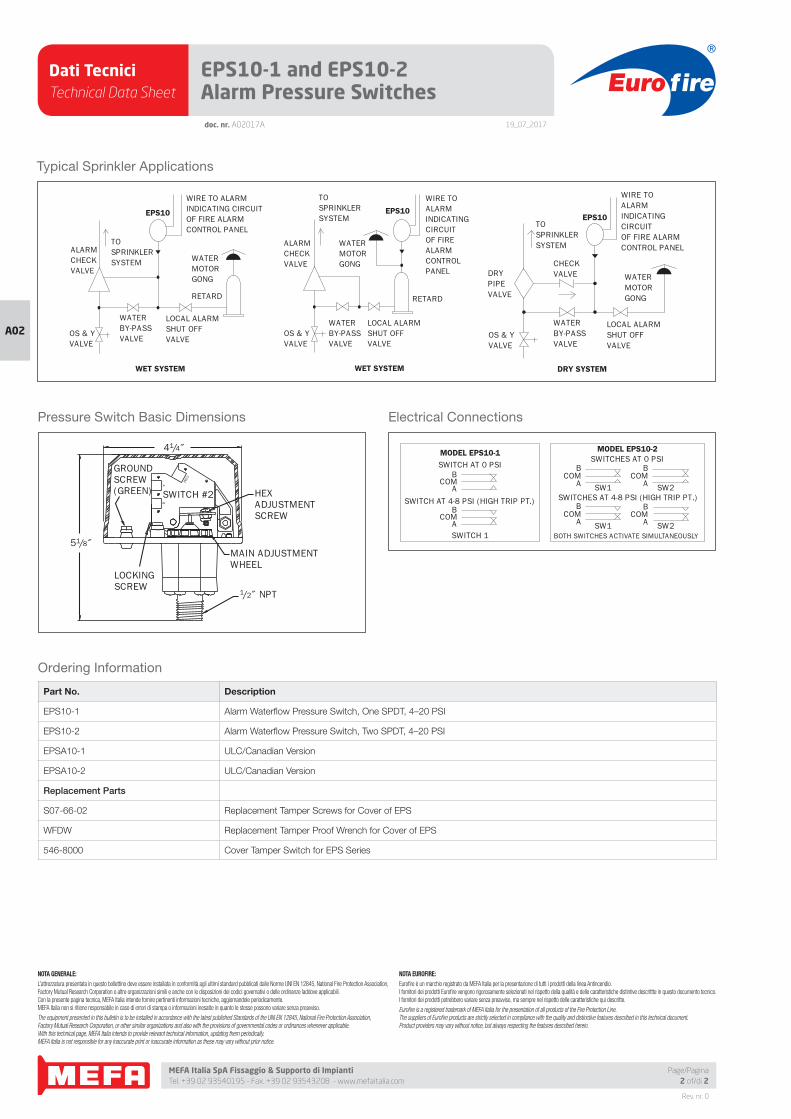
Dati TecniciTechnical Data Sheet
19_07_2017
Euro fire
MEFA Italia SpA Fissaggio & Supporto di Impianti Tel. +39 02 93540195 - Fax. +39 02 93543208 - www.mefaitalia.com
Rev. nr. 0
A02
Page/Pagina2 of/di 2
doc. nr. A02017A
EPS10-1 and EPS10-2 Alarm Pressure Switches
Typical Sprinkler Applications
ALARMCHECKVALVE
OS & YVALVE
WATERBY-PASSVALVE
LOCAL ALARMSHUT OFFVALVE
RETARD
WATERMOTORGONG
EPS10
WET SYSTEM
WIRE TO ALARMINDICATING CIRCUITOF FIRE ALARMCONTROL PANEL
TOSPRINKLERSYSTEM
ALARMCHECKVALVE
OS & YVALVE
WATERBY-PASSVALVE
LOCAL ALARMSHUT OFFVALVE
RETARD
WATERMOTORGONG
EPS10
WET SYSTEM
WIRE TO ALARMINDICATING CIRCUITOF FIRE ALARMCONTROLPANEL
TOSPRINKLERSYSTEM
DRYPIPEVALVE
OS & YVALVE
WATERBY-PASSVALVE
LOCAL ALARMSHUT OFFVALVE
WATERMOTORGONG
CHECKVALVE
EPS10
DRY SYSTEM
WIRE TO ALARMINDICATING CIRCUITOF FIRE ALARMCONTROL PANEL
TOSPRINKLERSYSTEM
Pressure Switch Basic Dimensions
HEXADJUSTMENTSCREW
MAIN ADJUSTMENTWHEEL
41/4˝
51/8˝
LOCKINGSCREW
1/2˝ NPTCOM
AB
GROUNDSCREW(GREEN) SWITCH #2
Electrical Connections
MODEL EPS10-1
ACOM
BSWITCH AT 0 PSI
SWITCH AT 4-8 PSI (HIGH TRIP PT.)B
COMASWITCH 1
MODEL EPS10-2SWITCHES AT 0 PSI
BCOM
A
BCOM
A
ACOM
B
ACOM
B
BOTH SWITCHES ACTIVATE SIMULTANEOUSLYSW1 SW2
SW1 SW2SWITCHES AT 4-8 PSI (HIGH TRIP PT.)
Ordering Information
Part No. Description
EPS10-1 Alarm Waterfl ow Pressure Switch, One SPDT, 4–20 PSI
EPS10-2 Alarm Waterfl ow Pressure Switch, Two SPDT, 4–20 PSI
EPSA10-1 ULC/Canadian Version
EPSA10-2 ULC/Canadian Version
Replacement Parts
S07-66-02 Replacement Tamper Screws for Cover of EPS
WFDW Replacement Tamper Proof Wrench for Cover of EPS
546-8000 Cover Tamper Switch for EPS Series
NOTA GENERALE:
L’attrezzatura presentata in questo bollettino deve essere installata in conformità agli ultimi standard pubblicati dalle Norme UNI EN 12845, National Fire Protection Association, Factory Mutual Research Corporation o altre organizzazioni simili e anche con le disposizioni dei codici governativi o delle ordinanze laddove applicabili.Con la presente pagina tecnica, MEFA Italia intende fornire pertinenti informazioni tecniche, aggiornandole periodicamente.MEFA Italia non si ritiene responsabile in caso di errori di stampa o informazioni inesatte in quanto le stesse possono variare senza preavviso.
The equipment presented in this bulletin is to be installed in accordance with the latest published Standards of the UNI EN 12845, National Fire Protection Association, Factory Mutual Research Corporation, or other similar organizations and also with the provisions of governmental codes or ordinances whenever applicable.With this technical page, MEFA Italia intends to provide relevant technical information, updating them periodically.MEFA Italia is not responsible for any inaccurate print or inaccurate information as these may vary without prior notice.
NOTA EUROFIRE:
Eurofi re è un marchio registrato da MEFA Italia per la presentazione di tutti i prodotti della linea Antincendio.I fornitori dei prodotti Eurofi re vengono rigorosamente selezionati nel rispetto della qualità e delle caratteristiche distintive descrittte in questo documento tecnico.I fornitori dei prodotti potrebbero variare senza preavviso, ma sempre nel rispetto delle caratteristiche qui descritte.
Eurofi re is a registered trademark of MEFA Italia for the presentation of all products of the Fire Protection Line.The suppliers of Eurofi re products are strictly selected in compliance with the quality and distinctive features described in this technical document.Product providers may vary without notice, but always respecting the features described herein.
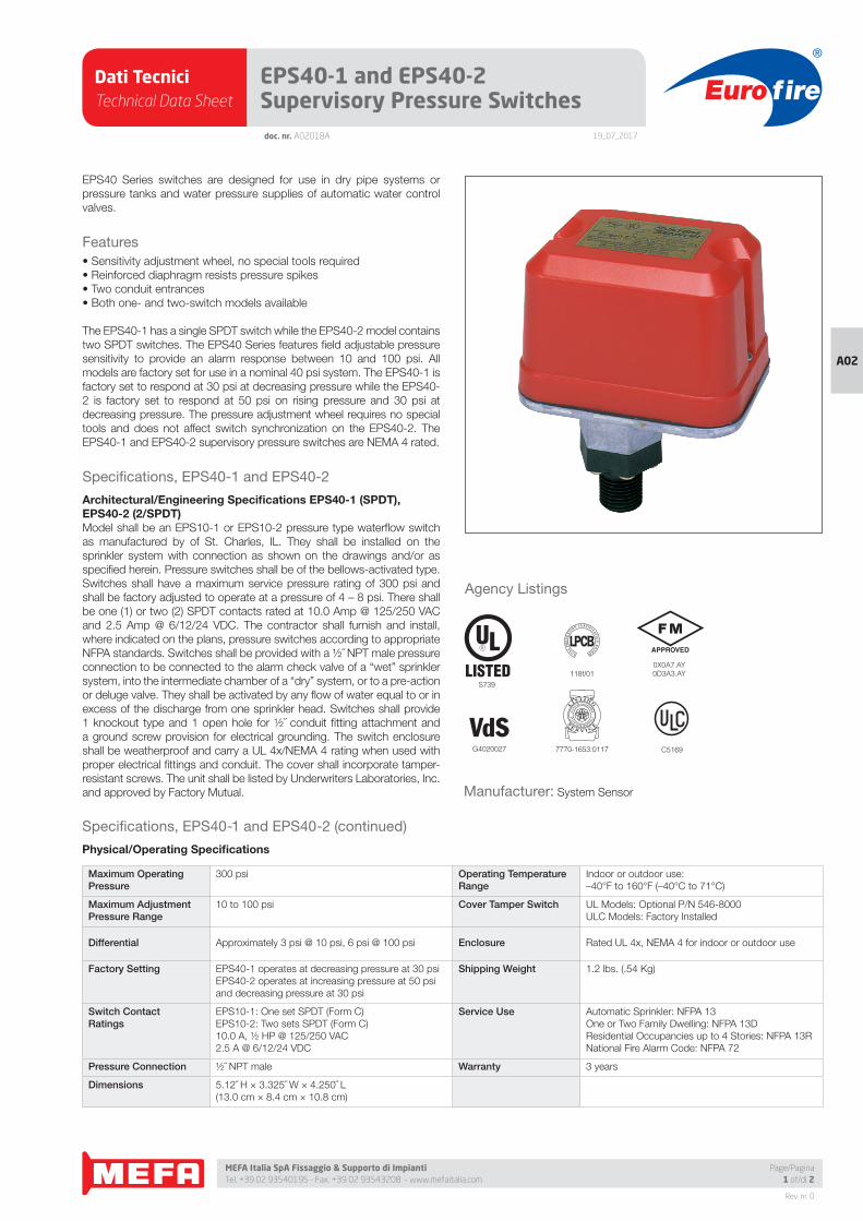
Dati TecniciTechnical Data Sheet
19_07_2017
Euro fire
MEFA Italia SpA Fissaggio & Supporto di Impianti Tel. +39 02 93540195 - Fax. +39 02 93543208 - www.mefaitalia.com
Rev. nr. 0
A02
Page/Pagina1 of/di 2
doc. nr. A02018A
EPS40-1 and EPS40-2Supervisory Pressure Switches
EPS40 Series switches are designed for use in dry pipe systems or
pressure tanks and water pressure supplies of automatic water control
valves.
Features
• Sensitivity adjustment wheel, no special tools required
• Reinforced diaphragm resists pressure spikes
• Two conduit entrances
• Both one- and two-switch models available
The EPS40-1 has a single SPDT switch while the EPS40-2 model contains
two SPDT switches. The EPS40 Series features fi eld adjustable pressure
sensitivity to provide an alarm response between 10 and 100 psi. All
models are factory set for use in a nominal 40 psi system. The EPS40-1 is
factory set to respond at 30 psi at decreasing pressure while the EPS40-
2 is factory set to respond at 50 psi on rising pressure and 30 psi at
decreasing pressure. The pressure adjustment wheel requires no special
tools and does not affect switch synchronization on the EPS40-2. The
EPS40-1 and EPS40-2 supervisory pressure switches are NEMA 4 rated.
Specifi cations, EPS40-1 and EPS40-2
Architectural/Engineering Specifi cations EPS40-1 (SPDT), EPS40-2 (2/SPDT)Model shall be an EPS10-1 or EPS10-2 pressure type waterfl ow switch
as manufactured by of St. Charles, IL. They shall be installed on the
sprinkler system with connection as shown on the drawings and/or as
specifi ed herein. Pressure switches shall be of the bellows-activated type.
Switches shall have a maximum service pressure rating of 300 psi and
shall be factory adjusted to operate at a pressure of 4 – 8 psi. There shall
be one (1) or two (2) SPDT contacts rated at 10.0 Amp @ 125/250 VAC
and 2.5 Amp @ 6/12/24 VDC. The contractor shall furnish and install,
where indicated on the plans, pressure switches according to appropriate
NFPA standards. Switches shall be provided with a ½˝ NPT male pressure
connection to be connected to the alarm check valve of a “wet” sprinkler
system, into the intermediate chamber of a “dry” system, or to a pre-action
or deluge valve. They shall be activated by any fl ow of water equal to or in
excess of the discharge from one sprinkler head. Switches shall provide
1 knockout type and 1 open hole for ½˝ conduit fi tting attachment and
a ground screw provision for electrical grounding. The switch enclosure
shall be weatherproof and carry a UL 4x/NEMA 4 rating when used with
proper electrical fi ttings and conduit. The cover shall incorporate tamper-
resistant screws. The unit shall be listed by Underwriters Laboratories, Inc.
and approved by Factory Mutual.
Agency Listings
S739
0X0A7.AY0D3A3.AY
VdSG4020027 7770-1653:0117
LPCB
LOSSP
RE
VE
NTIO
N CERTIFICATIO
NB
OA
RD
118f/01
C5169
Specifi cations, EPS40-1 and EPS40-2 (continued)
Physical/Operating Specifi cations
Maximum OperatingPressure
300 psi Operating Temperature Range
Indoor or outdoor use:
–40°F to 160°F (–40°C to 71°C)
Maximum AdjustmentPressure Range
10 to 100 psi Cover Tamper Switch UL Models: Optional P/N 546-8000
ULC Models: Factory Installed
Differential Approximately 3 psi @ 10 psi, 6 psi @ 100 psi Enclosure Rated UL 4x, NEMA 4 for indoor or outdoor use
Factory Setting EPS40-1 operates at decreasing pressure at 30 psi
EPS40-2 operates at increasing pressure at 50 psi
and decreasing pressure at 30 psi
Shipping Weight 1.2 lbs. (.54 Kg)
Switch Contact Ratings
EPS10-1: One set SPDT (Form C)
EPS10-2: Two sets SPDT (Form C)
10.0 A, ½ HP @ 125/250 VAC
2.5 A @ 6/12/24 VDC
Service Use Automatic Sprinkler: NFPA 13
One or Two Family Dwelling: NFPA 13D
Residential Occupancies up to 4 Stories: NFPA 13R
National Fire Alarm Code: NFPA 72
Pressure Connection ½˝ NPT male Warranty 3 years
Dimensions 5.12˝ H × 3.325˝ W × 4.250˝ L
(13.0 cm × 8.4 cm × 10.8 cm)
Manufacturer: System Sensor
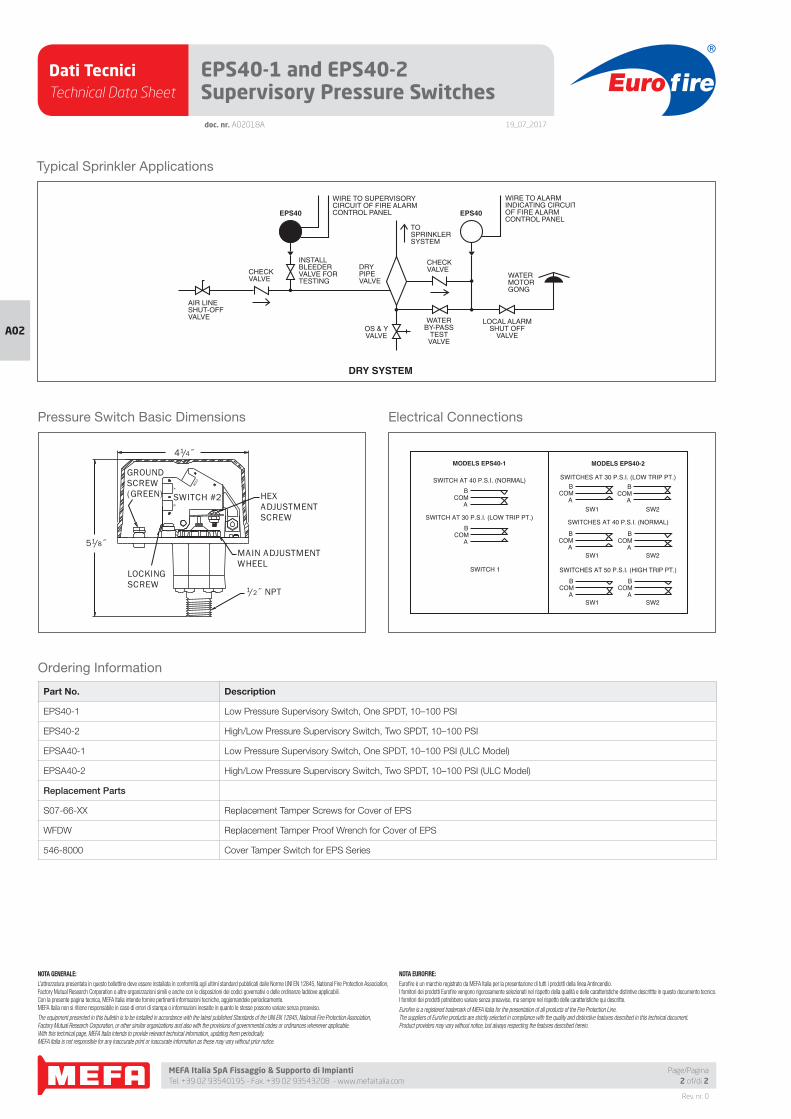
Dati TecniciTechnical Data Sheet
19_07_2017
Euro fire
MEFA Italia SpA Fissaggio & Supporto di Impianti Tel. +39 02 93540195 - Fax. +39 02 93543208 - www.mefaitalia.com
Rev. nr. 0
A02
Page/Pagina2 of/di 2
doc. nr. A02018A
EPS40-1 and EPS40-2Supervisory Pressure Switches
Typical Sprinkler Applications
DRYPIPEVALVE
OS & YVALVE
WATERBY-PASS
TESTVALVE
LOCAL ALARMSHUT OFF
VALVE
WATERMOTORGONG
CHECKVALVE
EPS40
CHECKVALVE
AIR LINESHUT-OFFVALVE
INSTALLBLEEDERVALVE FORTESTING
EPS40
DRY SYSTEM
WIRE TO SUPERVISORYCIRCUIT OF FIRE ALARMCONTROL PANEL
WIRE TO ALARMINDICATING CIRCUITOF FIRE ALARMCONTROL PANEL
TOSPRINKLERSYSTEM
Pressure Switch Basic Dimensions
HEXADJUSTMENTSCREW
MAIN ADJUSTMENTWHEEL
41/4˝
51/8˝
LOCKINGSCREW
1/2˝ NPTCOM
AB
GROUNDSCREW(GREEN) SWITCH #2
Electrical Connections
MODELS EPS40-1
SWITCH AT 40 P.S.I. (NORMAL)
SWITCH AT 30 P.S.I. (LOW TRIP PT.)B
COMA
ACOM
B
SWITCH 1
SW2SW1
SWITCHES AT 40 P.S.I. (NORMAL)
SWITCHES AT 30 P.S.I. (LOW TRIP PT.)
SW1 SW2
MODELS EPS40-2
SWITCHES AT 50 P.S.I. (HIGH TRIP PT.)
SW1 SW2
BCOM
A
BCOM
A
BCOM
A
ACOM
B
ACOM
B
ACOM
B
Ordering Information
Part No. Description
EPS40-1 Low Pressure Supervisory Switch, One SPDT, 10–100 PSI
EPS40-2 High/Low Pressure Supervisory Switch, Two SPDT, 10–100 PSI
EPSA40-1 Low Pressure Supervisory Switch, One SPDT, 10–100 PSI (ULC Model)
EPSA40-2 High/Low Pressure Supervisory Switch, Two SPDT, 10–100 PSI (ULC Model)
Replacement Parts
S07-66-XX Replacement Tamper Screws for Cover of EPS
WFDW Replacement Tamper Proof Wrench for Cover of EPS
546-8000 Cover Tamper Switch for EPS Series
NOTA GENERALE:
L’attrezzatura presentata in questo bollettino deve essere installata in conformità agli ultimi standard pubblicati dalle Norme UNI EN 12845, National Fire Protection Association, Factory Mutual Research Corporation o altre organizzazioni simili e anche con le disposizioni dei codici governativi o delle ordinanze laddove applicabili.Con la presente pagina tecnica, MEFA Italia intende fornire pertinenti informazioni tecniche, aggiornandole periodicamente.MEFA Italia non si ritiene responsabile in caso di errori di stampa o informazioni inesatte in quanto le stesse possono variare senza preavviso.
The equipment presented in this bulletin is to be installed in accordance with the latest published Standards of the UNI EN 12845, National Fire Protection Association, Factory Mutual Research Corporation, or other similar organizations and also with the provisions of governmental codes or ordinances whenever applicable.With this technical page, MEFA Italia intends to provide relevant technical information, updating them periodically.MEFA Italia is not responsible for any inaccurate print or inaccurate information as these may vary without prior notice.
NOTA EUROFIRE:
Eurofi re è un marchio registrato da MEFA Italia per la presentazione di tutti i prodotti della linea Antincendio.I fornitori dei prodotti Eurofi re vengono rigorosamente selezionati nel rispetto della qualità e delle caratteristiche distintive descrittte in questo documento tecnico.I fornitori dei prodotti potrebbero variare senza preavviso, ma sempre nel rispetto delle caratteristiche qui descritte.
Eurofi re is a registered trademark of MEFA Italia for the presentation of all products of the Fire Protection Line.The suppliers of Eurofi re products are strictly selected in compliance with the quality and distinctive features described in this technical document.Product providers may vary without notice, but always respecting the features described herein.
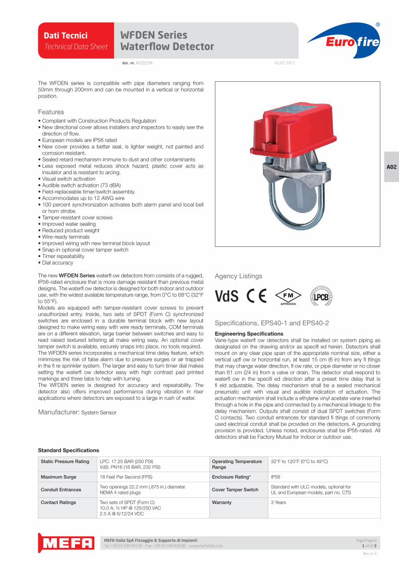
Dati TecniciTechnical Data Sheet
19_07_2017
Euro fire
MEFA Italia SpA Fissaggio & Supporto di Impianti Tel. +39 02 93540195 - Fax. +39 02 93543208 - www.mefaitalia.com
Rev. nr. 0
A02
Page/Pagina1 of/di 3
doc. nr. A02019A
WFDEN Series Waterfl ow Detector
The WFDEN series is compatible with pipe diameters ranging from
50mm through 200mm and can be mounted in a vertical or horizontal
position.
Features
• Compliant with Construction Products Regulation
• New directional cover allows installers and inspectors to easily see the
direction of fl ow.
• European models are IP56 rated
• New cover provides a better seal, is lighter weight, not painted and
corrosion resistant.
• Sealed retard mechanism immune to dust and other contaminants
• Less exposed metal reduces shock hazard, plastic cover acts as
insulator and is resistant to arcing.
• Visual switch activation
• Audible switch activation (73 dBA)
• Field-replaceable timer/switch assembly.
• Accommodates up to 12 AWG wire
• 100 percent synchronization activates both alarm panel and local bell
or horn strobe.
• Tamper-resistant cover screws
• Improved water sealing
• Reduced product weight
• Wire-ready terminals
• Improved wiring with new terminal block layout
• Snap-in optional cover tamper switch
• Timer repeatability
• Dial accuracy
The new WFDEN Series waterfl ow detectors from consists of a rugged,
IP56-rated enclosure that is more damage resistant than previous metal
designs. The waterfl ow detector is designed for both indoor and outdoor
use, with the widest available temperature range, from 0°C to 68°C (32°F
to 55°F).
Models are equipped with tamper-resistant cover screws to prevent
unauthorized entry. Inside, two sets of SPDT (Form C) synchronized
switches are enclosed in a durable terminal block with new layout
designed to make wiring easy with wire ready terminals, COM terminals
are on a different elevation, large barrier between switches and easy to
read raised textured lettering all make wiring easy. An optional cover
tamper switch is available, securely snaps into place, no tools required.
The WFDEN series incorporates a mechanical time delay feature, which
minimizes the risk of false alarm due to pressure surges or air trapped
in the fi re sprinkler system. The larger and easy to turn timer dial makes
setting the waterfl ow detector easy with high contrast pad printed
markings and three tabs to help with turning.
The WFDEN series is designed for accuracy and repeatability. The
detector also offers improved performance during vibration in riser
applications where detectors are exposed to a large in rush of water.
Manufacturer: System Sensor
Agency Listings
Standard Specifi cations
Static Pressure Rating LPC: 17.25 BAR (250 PSI)
VdS: PN16 (16 BAR, 232 PSI)
Operating Temperature Range
32°F to 120°F (0°C to 49°C)
Maximum Surge 18 Feet Per Second (FPS) Enclosure Rating* IP56
Conduit EntrancesTwo openings 22.2 mm (.875 in.) diameter.
NEMA 4 rated plugsCover Tamper Switch
Standard with ULC models, optional for
UL and European models, part no. CTS
Contact Ratings Two sets of SPDT (Form C)
10.0 A, ½ HP @ 125/250 VAC
2.5 A @ 6/12/24 VDC
Warranty 3 Years
Specifi cations, EPS40-1 and EPS40-2
Engineering Specifi cationsVane-type waterfl ow detectors shall be installed on system piping as
designated on the drawing and/or as specifi ed herein. Detectors shall
mount on any clear pipe span of the appropriate nominal size, either a
vertical upfl ow or horizontal run, at least 15 cm (6 in) from any fi ttings
that may change water direction, fl ow rate, or pipe diameter or no closer
than 61 cm (24 in) from a valve or drain. The detector shall respond to
waterfl ow in the specifi ed direction after a preset time delay that is
fi eld adjustable. The delay mechanism shall be a sealed mechanical
pneumatic unit with visual and audible indication of actuation. The
actuation mechanism shall include a ethylene vinyl acetate vane inserted
through a hole in the pipe and connected by a mechanical linkage to the
delay mechanism. Outputs shall consist of dual SPDT switches (Form
C contacts). Two conduit entrances for standard fi ttings of commonly
used electrical conduit shall be provided on the detectors. A grounding
provision is provided. Unless noted, enclosures shall be IP56-rated. All
detectors shall be Factory Mutual for indoor or outdoor use.
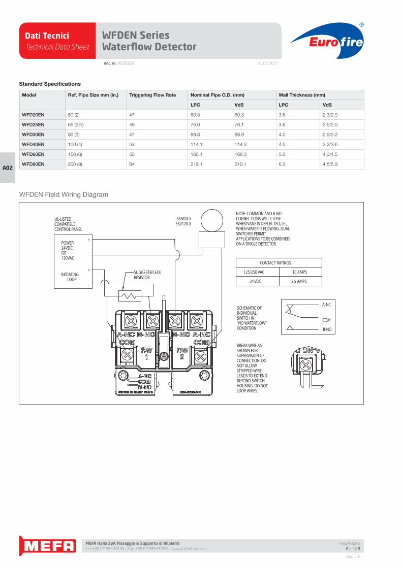
Dati TecniciTechnical Data Sheet
19_07_2017
Euro fire
MEFA Italia SpA Fissaggio & Supporto di Impianti Tel. +39 02 93540195 - Fax. +39 02 93543208 - www.mefaitalia.com
Rev. nr. 0
A02
Page/Pagina2 of/di 3
doc. nr. A02019A
WFDEN Series Waterfl ow Detector
WFDEN Field Wiring Diagram
CONTACT RATINGS
125/250 VAC 10 AMPS
24 VDC 2.5 AMPS
UL-LISTEDCOMPATIBLECONTROL PANEL
POWER24VDCOR120VAC
INITIATINGLOOP
SSM24-XSSV120-X
NOTE: COMMON AND B-NOCONNECTIONS WILL CLOSEWHEN VANE IS DEFLECTED, I.E.,WHEN WATER IS FLOWING. DUALSWITCHES PERMITAPPLICATIONS TO BE COMBINEDON A SINGLE DETECTOR.
SCHEMATIC OFINDIVIDUALSWITCH IN"NO WATERFLOW"CONDITION
BREAK WIRE ASSHOWN FORSUPERVISION OFCONNECTION. DONOT ALLOWSTRIPPED WIRELEADS TO EXTENDBEYOND SWITCHHOUSING. DO NOTLOOP WIRES.
A-NC
B-NO
COM
SUGGESTED EOLRESISTOR
+
-
+
-
Standard Specifi cations
Model Ref. Pipe Size mm (in.) Triggering Flow Rate Nominal Pipe O.D. (mm) Wall Thickness (mm)
LPC VdS LPC VdS
WFD20EN 50 (2) 47 60.3 60.3 3.6 2.3/2.9
WFD25EN 65 (2½) 49 76.0 76.1 3.6 2.6/2.9
WFD30EN 80 (3) 47 88.8 88.9 4.0 2.9/3.2
WFD40EN 100 (4) 53 114.1 114.3 4.5 3.2/3.6
WFD60EN 150 (6) 55 165.1 168.3 5.0 4.0/4.5
WFD80EN 200 (8) 64 219.1 219.1 6.3 4.5/5.9
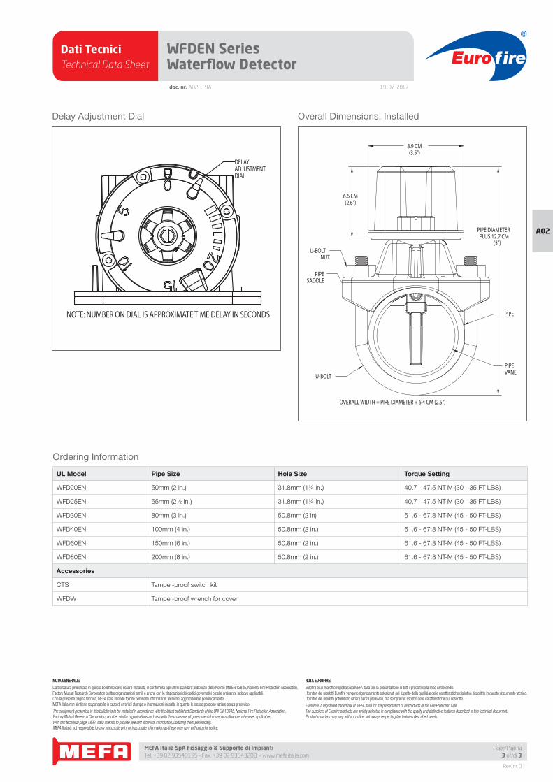
Dati TecniciTechnical Data Sheet
19_07_2017
Euro fire
MEFA Italia SpA Fissaggio & Supporto di Impianti Tel. +39 02 93540195 - Fax. +39 02 93543208 - www.mefaitalia.com
NOTA GENERALE:
L’attrezzatura presentata in questo bollettino deve essere installata in conformità agli ultimi standard pubblicati dalle Norme UNI EN 12845, National Fire Protection Association, Factory Mutual Research Corporation o altre organizzazioni simili e anche con le disposizioni dei codici governativi o delle ordinanze laddove applicabili.Con la presente pagina tecnica, MEFA Italia intende fornire pertinenti informazioni tecniche, aggiornandole periodicamente.MEFA Italia non si ritiene responsabile in caso di errori di stampa o informazioni inesatte in quanto le stesse possono variare senza preavviso.
The equipment presented in this bulletin is to be installed in accordance with the latest published Standards of the UNI EN 12845, National Fire Protection Association, Factory Mutual Research Corporation, or other similar organizations and also with the provisions of governmental codes or ordinances whenever applicable.With this technical page, MEFA Italia intends to provide relevant technical information, updating them periodically.MEFA Italia is not responsible for any inaccurate print or inaccurate information as these may vary without prior notice.
NOTA EUROFIRE:
Eurofi re è un marchio registrato da MEFA Italia per la presentazione di tutti i prodotti della linea Antincendio.I fornitori dei prodotti Eurofi re vengono rigorosamente selezionati nel rispetto della qualità e delle caratteristiche distintive descrittte in questo documento tecnico.I fornitori dei prodotti potrebbero variare senza preavviso, ma sempre nel rispetto delle caratteristiche qui descritte.
Eurofi re is a registered trademark of MEFA Italia for the presentation of all products of the Fire Protection Line.The suppliers of Eurofi re products are strictly selected in compliance with the quality and distinctive features described in this technical document.Product providers may vary without notice, but always respecting the features described herein.
Rev. nr. 0
A02
Page/Pagina3 of/di 3
doc. nr. A02019A
WFDEN Series Waterfl ow Detector
UL Model Pipe Size Hole Size Torque Setting
WFD20EN 50mm (2 in.) 31.8mm (1¼ in.) 40.7 - 47.5 NT-M (30 - 35 FT-LBS)
WFD25EN 65mm (2½ in.) 31.8mm (1¼ in.) 40.7 - 47.5 NT-M (30 - 35 FT-LBS)
WFD30EN 80mm (3 in.) 50.8mm (2 in) 61.6 - 67.8 NT-M (45 - 50 FT-LBS)
WFD40EN 100mm (4 in.) 50.8mm (2 in.) 61.6 - 67.8 NT-M (45 - 50 FT-LBS)
WFD60EN 150mm (6 in.) 50.8mm (2 in.) 61.6 - 67.8 NT-M (45 - 50 FT-LBS)
WFD80EN 200mm (8 in.) 50.8mm (2 in.) 61.6 - 67.8 NT-M (45 - 50 FT-LBS)
Accessories
CTS Tamper-proof switch kit
WFDW Tamper-proof wrench for cover
Delay Adjustment Dial Overall Dimensions, Installed
NOTE: NUMBER ON DIAL IS APPROXIMATE TIME DELAY IN SECONDS.
DELAYADJUSTMENTDIAL
8.9 CM(3.5")
6.6 CM(2.6")
PIPE DIAMETERPLUS 12.7 CM
(5")
PIPEVANE
OVERALL WIDTH = PIPE DIAMETER + 6.4 CM (2.5")
U-BOLTNUT
PIPESADDLE
U-BOLT
PIPE
Ordering Information
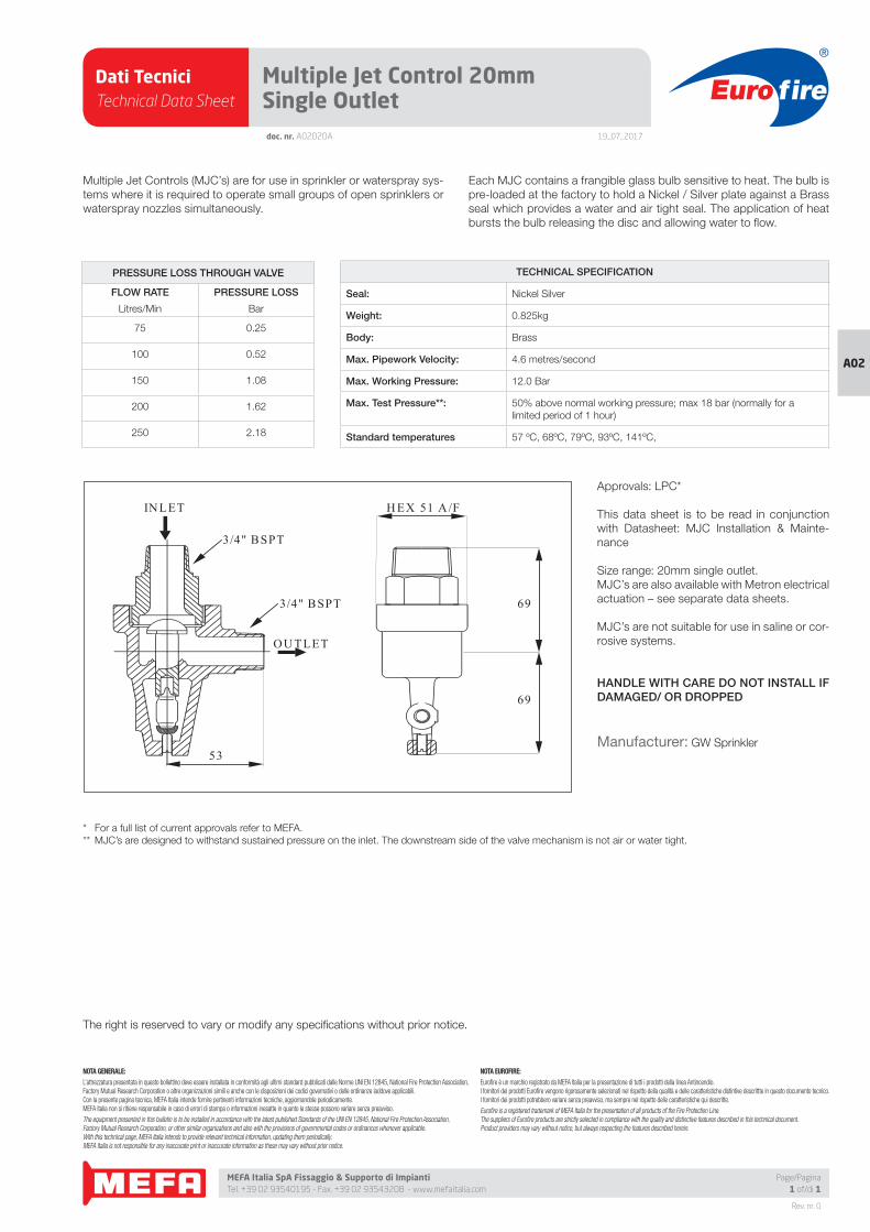
Dati TecniciTechnical Data Sheet
19_07_2017
Euro fire
MEFA Italia SpA Fissaggio & Supporto di Impianti Tel. +39 02 93540195 - Fax. +39 02 93543208 - www.mefaitalia.com
Page/Pagina1 of/di 1
NOTA GENERALE:
L’attrezzatura presentata in questo bollettino deve essere installata in conformità agli ultimi standard pubblicati dalle Norme UNI EN 12845, National Fire Protection Association, Factory Mutual Research Corporation o altre organizzazioni simili e anche con le disposizioni dei codici governativi o delle ordinanze laddove applicabili.Con la presente pagina tecnica, MEFA Italia intende fornire pertinenti informazioni tecniche, aggiornandole periodicamente.MEFA Italia non si ritiene responsabile in caso di errori di stampa o informazioni inesatte in quanto le stesse possono variare senza preavviso.
The equipment presented in this bulletin is to be installed in accordance with the latest published Standards of the UNI EN 12845, National Fire Protection Association, Factory Mutual Research Corporation, or other similar organizations and also with the provisions of governmental codes or ordinances whenever applicable.With this technical page, MEFA Italia intends to provide relevant technical information, updating them periodically.MEFA Italia is not responsible for any inaccurate print or inaccurate information as these may vary without prior notice.
NOTA EUROFIRE:
Eurofi re è un marchio registrato da MEFA Italia per la presentazione di tutti i prodotti della linea Antincendio.I fornitori dei prodotti Eurofi re vengono rigorosamente selezionati nel rispetto della qualità e delle caratteristiche distintive descrittte in questo documento tecnico.I fornitori dei prodotti potrebbero variare senza preavviso, ma sempre nel rispetto delle caratteristiche qui descritte.
Eurofi re is a registered trademark of MEFA Italia for the presentation of all products of the Fire Protection Line.The suppliers of Eurofi re products are strictly selected in compliance with the quality and distinctive features described in this technical document.Product providers may vary without notice, but always respecting the features described herein.
Rev. nr. 0
A02
doc. nr. A02020A
Multiple Jet Control 20mm Single Outlet
Multiple Jet Controls (MJC’s) are for use in sprinkler or waterspray sys-
tems where it is required to operate small groups of open sprinklers or
waterspray nozzles simultaneously.
Each MJC contains a frangible glass bulb sensitive to heat. The bulb is
pre-loaded at the factory to hold a Nickel / Silver plate against a Brass
seal which provides a water and air tight seal. The application of heat
bursts the bulb releasing the disc and allowing water to fl ow.
H EX 51 A/F
69
69
INLET
OU TLET
3/4" BSPT
3/4" BSPT
53
The right is reserved to vary or modify any specifi cations without prior notice.
TECHNICAL SPECIFICATION
Seal: Nickel Silver
Weight: 0.825kg
Body: Brass
Max. Pipework Velocity: 4.6 metres/second
Max. Working Pressure: 12.0 Bar
Max. Test Pressure**: 50% above normal working pressure; max 18 bar (normally for a
limited period of 1 hour)
Standard temperatures 57 ºC, 68ºC, 79ºC, 93ºC, 141ºC,
PRESSURE LOSS THROUGH VALVE
FLOW RATE PRESSURE LOSS
Litres/Min Bar
75 0.25
100 0.52
150 1.08
200 1.62
250 2.18
Approvals: LPC*
This data sheet is to be read in conjunction
with Datasheet: MJC Installation & Mainte-
nance
Size range: 20mm single outlet.
MJC’s are also available with Metron electrical
actuation – see separate data sheets.
MJC’s are not suitable for use in saline or cor-
rosive systems.
HANDLE WITH CARE DO NOT INSTALL IF DAMAGED/ OR DROPPED
Manufacturer: GW Sprinkler
* For a full list of current approvals refer to MEFA.
** MJC’s are designed to withstand sustained pressure on the inlet. The downstream side of the valve mechanism is not air or water tight.
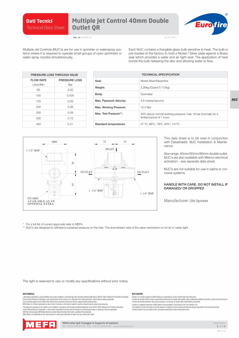
Dati TecniciTechnical Data Sheet
19_07_2017
Euro fire
MEFA Italia SpA Fissaggio & Supporto di Impianti Tel. +39 02 93540195 - Fax. +39 02 93543208 - www.mefaitalia.com
Page/Pagina1 of/di 1
NOTA GENERALE:
L’attrezzatura presentata in questo bollettino deve essere installata in conformità agli ultimi standard pubblicati dalle Norme UNI EN 12845, National Fire Protection Association, Factory Mutual Research Corporation o altre organizzazioni simili e anche con le disposizioni dei codici governativi o delle ordinanze laddove applicabili.Con la presente pagina tecnica, MEFA Italia intende fornire pertinenti informazioni tecniche, aggiornandole periodicamente.MEFA Italia non si ritiene responsabile in caso di errori di stampa o informazioni inesatte in quanto le stesse possono variare senza preavviso.
The equipment presented in this bulletin is to be installed in accordance with the latest published Standards of the UNI EN 12845, National Fire Protection Association, Factory Mutual Research Corporation, or other similar organizations and also with the provisions of governmental codes or ordinances whenever applicable.With this technical page, MEFA Italia intends to provide relevant technical information, updating them periodically.MEFA Italia is not responsible for any inaccurate print or inaccurate information as these may vary without prior notice.
NOTA EUROFIRE:
Eurofi re è un marchio registrato da MEFA Italia per la presentazione di tutti i prodotti della linea Antincendio.I fornitori dei prodotti Eurofi re vengono rigorosamente selezionati nel rispetto della qualità e delle caratteristiche distintive descrittte in questo documento tecnico.I fornitori dei prodotti potrebbero variare senza preavviso, ma sempre nel rispetto delle caratteristiche qui descritte.
Eurofi re is a registered trademark of MEFA Italia for the presentation of all products of the Fire Protection Line.The suppliers of Eurofi re products are strictly selected in compliance with the quality and distinctive features described in this technical document.Product providers may vary without notice, but always respecting the features described herein.
Rev. nr. 0
A02
doc. nr. A02021A
Multiple Jet Control 40mm Double Outlet QR
Multiple Jet Controls (MJC’s) are for use in sprinkler or waterspray sys-
tems where it is required to operate small groups of open sprinklers or
water spray nozzles simultaneously.
Each MJC contains a frangible glass bulb sensitive to heat. The bulb is
pre-loaded at the factory to hold a Nickel / Silver plate against a Brass
seal which provides a water and air tight seal. The application of heat
bursts the bulb releasing the disc and allowing water to fl ow.
1 1/4" BSP
OUTLET
1 1/4" BSP
OUTLET
INLET
GUARD AVAILABLE AS AN OPTIONAL EXTRA
1 1/2" BSP
9778
The right is reserved to vary or modify any specifi cations without prior notice.
TECHNICAL SPECIFICATION
Seal: Nickel Silver/Neoprene
Weight: 2.26kg (Guard 0.112kg)
Body: Gunmetal
Max. Pipework Velocity: 4.6 metres/second
Max. Working Pressure: 12.0 Bar
Max. Test Pressure**: 50% above normal working pressure; max 18 bar (normally for a
limited period of 1 hour)
Standard temperatures 57 ºC, 68ºC, 79ºC, 93ºC, 141ºC
PRESSURE LOSS THROUGH VALVE
FLOW RATE PRESSURE LOSS
Litres/Min Bar
60 0.02
100 0.035
125 0.05
200 0.06
250 0.09
300 0.15
350 0.21
This data sheet is to be read in conjunction
with Datasheets: MJC Installation & Mainte-
nance
Size range: 40mm/50mm/80mm double outlet.
MJC’s are also available with Metron electrical
activation – see separate data sheet.
MJC’s are not suitable for use in saline or cor-
rosive systems.
HANDLE WITH CARE. DO NOT INSTALL IF DAMAGED/ OR DROPPED
Manufacturer: GW Sprinkler
* For a full list of current approvals refer to MEFA.
** MJC’s are designed to withstand sustained pressure on the inlet. The downstream side of the valve mechanism is not air or water tight.
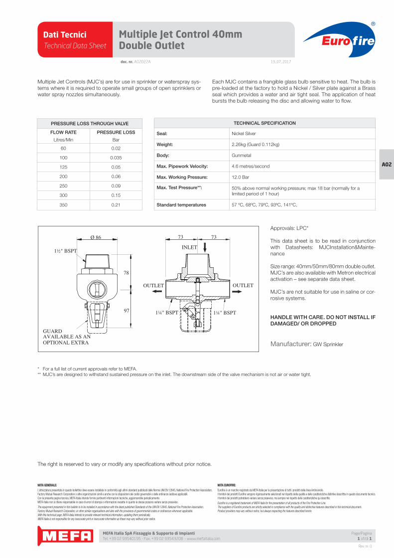
Dati TecniciTechnical Data Sheet
19_07_2017
Euro fire
MEFA Italia SpA Fissaggio & Supporto di Impianti Tel. +39 02 93540195 - Fax. +39 02 93543208 - www.mefaitalia.com
Page/Pagina1 of/di 1
NOTA GENERALE:
L’attrezzatura presentata in questo bollettino deve essere installata in conformità agli ultimi standard pubblicati dalle Norme UNI EN 12845, National Fire Protection Association, Factory Mutual Research Corporation o altre organizzazioni simili e anche con le disposizioni dei codici governativi o delle ordinanze laddove applicabili.Con la presente pagina tecnica, MEFA Italia intende fornire pertinenti informazioni tecniche, aggiornandole periodicamente.MEFA Italia non si ritiene responsabile in caso di errori di stampa o informazioni inesatte in quanto le stesse possono variare senza preavviso.
The equipment presented in this bulletin is to be installed in accordance with the latest published Standards of the UNI EN 12845, National Fire Protection Association, Factory Mutual Research Corporation, or other similar organizations and also with the provisions of governmental codes or ordinances whenever applicable.With this technical page, MEFA Italia intends to provide relevant technical information, updating them periodically.MEFA Italia is not responsible for any inaccurate print or inaccurate information as these may vary without prior notice.
NOTA EUROFIRE:
Eurofi re è un marchio registrato da MEFA Italia per la presentazione di tutti i prodotti della linea Antincendio.I fornitori dei prodotti Eurofi re vengono rigorosamente selezionati nel rispetto della qualità e delle caratteristiche distintive descrittte in questo documento tecnico.I fornitori dei prodotti potrebbero variare senza preavviso, ma sempre nel rispetto delle caratteristiche qui descritte.
Eurofi re is a registered trademark of MEFA Italia for the presentation of all products of the Fire Protection Line.The suppliers of Eurofi re products are strictly selected in compliance with the quality and distinctive features described in this technical document.Product providers may vary without notice, but always respecting the features described herein.
Rev. nr. 0
A02
doc. nr. A02022A
Multiple Jet Control 40mm Double Outlet
Multiple Jet Controls (MJC’s) are for use in sprinkler or waterspray sys-
tems where it is required to operate small groups of open sprinklers or
water spray nozzles simultaneously.
Each MJC contains a frangible glass bulb sensitive to heat. The bulb is
pre-loaded at the factory to hold a Nickel / Silver plate against a Brass
seal which provides a water and air tight seal. The application of heat
bursts the bulb releasing the disc and allowing water to fl ow.
1½" BSPT
1¼" BSPT 1¼" BSPT
OUTLETOUTLET
INLET
7373
97
78
Ø 86
GUARDAVAILABLE AS ANOPTIONAL EXTRA
The right is reserved to vary or modify any specifi cations without prior notice.
TECHNICAL SPECIFICATION
Seal: Nickel Silver
Weight: 2.26kg (Guard 0.112kg)
Body: Gunmetal
Max. Pipework Velocity: 4.6 metres/second
Max. Working Pressure: 12.0 Bar
Max. Test Pressure**: 50% above normal working pressure; max 18 bar (normally for a
limited period of 1 hour)
Standard temperatures 57 ºC, 68ºC, 79ºC, 93ºC, 141ºC,
PRESSURE LOSS THROUGH VALVE
FLOW RATE PRESSURE LOSS
Litres/Min Bar
60 0.02
100 0.035
125 0.05
200 0.06
250 0.09
300 0.15
350 0.21
Approvals: LPC*
This data sheet is to be read in conjunction
with Datasheets: MJCInstallation&Mainte-
nance
Size range: 40mm/50mm/80mm double outlet.
MJC’s are also available with Metron electrical
activation – see separate data sheet.
MJC’s are not suitable for use in saline or cor-
rosive systems.
HANDLE WITH CARE. DO NOT INSTALL IF DAMAGED/ OR DROPPED
Manufacturer: GW Sprinkler
* For a full list of current approvals refer to MEFA.
** MJC’s are designed to withstand sustained pressure on the inlet. The downstream side of the valve mechanism is not air or water tight.
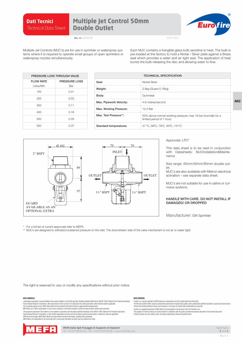
Dati TecniciTechnical Data Sheet
19_07_2017
Euro fire
MEFA Italia SpA Fissaggio & Supporto di Impianti Tel. +39 02 93540195 - Fax. +39 02 93543208 - www.mefaitalia.com
Page/Pagina1 of/di 1
NOTA GENERALE:
L’attrezzatura presentata in questo bollettino deve essere installata in conformità agli ultimi standard pubblicati dalle Norme UNI EN 12845, National Fire Protection Association, Factory Mutual Research Corporation o altre organizzazioni simili e anche con le disposizioni dei codici governativi o delle ordinanze laddove applicabili.Con la presente pagina tecnica, MEFA Italia intende fornire pertinenti informazioni tecniche, aggiornandole periodicamente.MEFA Italia non si ritiene responsabile in caso di errori di stampa o informazioni inesatte in quanto le stesse possono variare senza preavviso.
The equipment presented in this bulletin is to be installed in accordance with the latest published Standards of the UNI EN 12845, National Fire Protection Association, Factory Mutual Research Corporation, or other similar organizations and also with the provisions of governmental codes or ordinances whenever applicable.With this technical page, MEFA Italia intends to provide relevant technical information, updating them periodically.MEFA Italia is not responsible for any inaccurate print or inaccurate information as these may vary without prior notice.
NOTA EUROFIRE:
Eurofi re è un marchio registrato da MEFA Italia per la presentazione di tutti i prodotti della linea Antincendio.I fornitori dei prodotti Eurofi re vengono rigorosamente selezionati nel rispetto della qualità e delle caratteristiche distintive descrittte in questo documento tecnico.I fornitori dei prodotti potrebbero variare senza preavviso, ma sempre nel rispetto delle caratteristiche qui descritte.
Eurofi re is a registered trademark of MEFA Italia for the presentation of all products of the Fire Protection Line.The suppliers of Eurofi re products are strictly selected in compliance with the quality and distinctive features described in this technical document.Product providers may vary without notice, but always respecting the features described herein.
Rev. nr. 0
A02
doc. nr. A02023A
Multiple Jet Control 50mm Double Outlet
Multiple Jet Controls (MJC’s) are for use in sprinkler or waterspray sys-
tems where it is required to operate small groups of open sprinklers or
waterspray nozzles simultaneously.
Each MJC contains a frangible glass bulb sensitive to heat. The bulb is
pre-loaded at the factory to hold a Nickel / Silver plate against a Brass
seal which provides a water and air tight seal. The application of heat
bursts the bulb releasing the disc and allowing water to fl ow.
2" BSPT
1½" BSPT 1½" BSPT
OUTLETOUTLET
INLET
7979
97
89
Ø 102
GUARDAVAILABLE AS ANOPTIONAL EXTRA
The right is reserved to vary or modify any specifi cations without prior notice.
TECHNICAL SPECIFICATION
Seal: Nickel Silver
Weight: 2.9kg (Guard 0.16kg)
Body: Gunmetal
Max. Pipework Velocity: 4.6 metres/second
Max. Working Pressure: 12.0 Bar
Max. Test Pressure**: 50% above normal working pressure; max 18 bar (normally for a
limited period of 1 hour)
Standard temperatures 57 ºC, 68ºC, 79ºC, 93ºC, 141ºC
PRESSURE LOSS THROUGH VALVE
FLOW RATE PRESSURE LOSS
Litres/Min Bar
100 0.01
200 0.03
300 0.11
400 0.18
500 0.28
550 0.37
Approvals: LPC*
This data sheet is to be read in conjunction
with Datasheets: MJCInstallation&Mainte-
nance
Size range: 40mm/50mm/80mm double out-
let.
MJC’s are also available with Metron electrical
activation – see separate data sheet.
MJC’s are not suitable for use in saline or cor-
rosive systems.
HANDLE WITH CARE. DO NOT INSTALL IF DAMAGED/ OR DROPPED
Manufacturer: GW Sprinkler
* For a full list of current approvals refer to MEFA.
** MJC’s are designed to withstand sustained pressure on the inlet. The downstream side of the valve mechanism is not air or water tight.
Related Documents