OVERHEAT EXPLOSION FIRE www.prevent-a-fire.eu LICO Electronics GmbH, A-2320 Kledering LICO Hungaria Kft, H-2030 Erd LICO Mecatronic, RO-540526 Targu-Mures www.prevent-a-fire.eu STAY COOL AVOID Wir haben die richtige Lösung um Hitze von 60 - 510°C zu erfassen und Überhitzung, Brand & Explosion zu vermeiden. We have the right solution for you to detect Heat from 60 - 510°C and avoid Overheat, Fire & Explosion

Welcome message from author
This document is posted to help you gain knowledge. Please leave a comment to let me know what you think about it! Share it to your friends and learn new things together.
Transcript

OVERHEATEXPLOSION
FIRE
www.prevent-a-fire.eu
LICO Electronics GmbH, A-2320 KlederingLICO Hungaria Kft, H-2030 Erd
LICO Mecatronic, RO-540526 Targu-Mureswww.prevent-a-fire.eu
STAY COOL
AVOID
Wir haben die richtige Lösung um Hitze von60 - 510°C zu erfassen und Überhitzung,Brand & Explosion zu vermeiden.
We have the right solution for you to detectHeat from 60 - 510°C and avoid Overheat,
Fire & Explosion

PAF - PREVENT-A-FIRE www.prevent-a-fire.eu
www.prevent-a-fire.euLICO Electronics GmbH, A-2320 Kledering, Klederinger Str.31, [email protected] [email protected] Tel +43 1 706 43 000
LICO Hungaria Kft, H-2030 Erd, Raba u. 4, Email [email protected], [email protected] Tel + 36 23 520 113
LICO Mecatronic S.R.L, RO-540526 Targu-Mures, Str.Bucinului Nr.2B / 19, Email [email protected], Tel +40 365 807 497
PAF - The Smart Heat- & Fire Detection SystemDetection and Alarm Devices Fire warning is a basic function and often early Detection
of excessive high temperatures is most critical.Excessive heat, even without the presence of smoke, canbe a potential hazard of fire or explosion.The prevention of a potential fire, caused by excessiveheat, allows corrective action to avoid igniting flames. In conclusion - effective action can save lifes and protecthigh value buildings and assets.
The system can be used for single or unused Heat Detec-tion using 2 equal switching temperatures. Ex e & Ex dboxes available. It also can be using by programming 2(or more) different switching temperatures. Also the use ofdifferent Salt-filled Inconel wires is possible. The flexibleand highly effective system gives accurate data acquisitionand warning of excessive high temperatures.
Application References:Heating plants, Heating Rooms, Dryers, Exhaust systems,Wind power generators, Gasturbines, Industrial plants, Enginerooms, Compressors, Chemical Plants & many more.
General Information for all PAF-Systems:
The Heat Detectcion for special applications. It can add safety in Fire-/Explosion prevention. The System contains aLICO Alarmpanel, 1 or 2 HDL Heat Detectors LICO and optionally an ATEX-certified Power Supply. All units are Dust-, Humidity- and Temperature-safe, switching contacts hermetically sealed (IP67) Various rate compensated switching temperatures from 60 – 385°C are available. Options: Switch fully stainless steel, Ex-certified Low VoltagePower Supply, Industrial Server UPS
60 - 510°C
124 - 407°C

www.fenwal-direct.eu - www.prevent-a-fire.eu
HDL 1-6 Heat Detector LICO – Ex e & Ex d
encapsulated Heat-, Overheat- & Fire-Detectors www.prevent-a-fire.eu
HDL-5- 28000
HDL-2
HDL-3
HDL-5
HDL-1
HDL-4
HDL-3-XL
HDL-5
HDL-6
HDL-4
LICO Electronics GmbH, Klederinger Str. 31, A-2320 Kledering, Austria [email protected] www.lico.at
LICO Hungaria Kft, Raba u.4, H-2030 Erd, Hungary [email protected] / [email protected] www.lico.hu
LICO Mecatronic S.R.L. RO-540526 Targu-Mures, Str.Bucinului Nr.2B Romania. [email protected] www.lico.ro
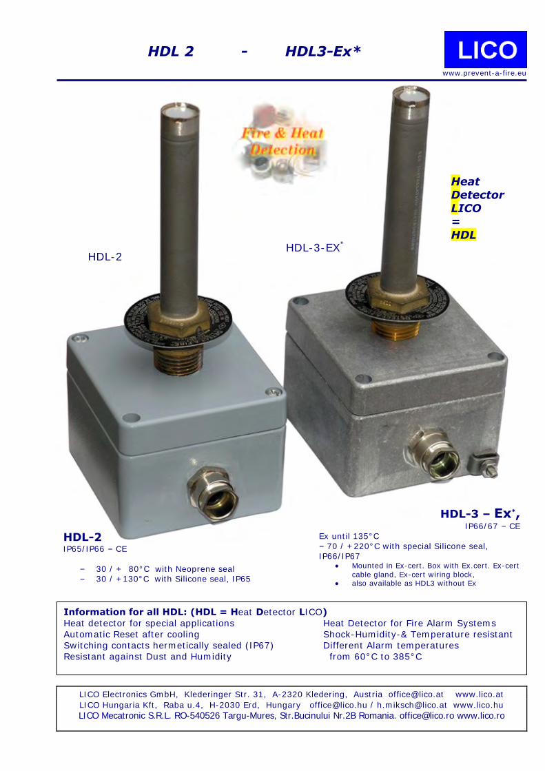
HDL-2 HDL-3-EX*
HDL-3 – Ex*, IP66/67 – CE
Ex until 135°C – 70 / +220°C with special Silicone seal, IP66/IP67
Mounted in Ex-cert. Box with Ex.cert. Ex-cert cable gland, Ex-cert wiring block,
also available as HDL3 without Ex
HDL-2 IP65/IP66 – CE
– 30 / + 80°C with Neoprene seal – 30 / +130°C with Silicone seal, IP65
Information for all HDL: (HDL = Heat Detector LICO)
Heat detector for special applications Heat Detector for Fire Alarm Systems
Automatic Reset after cooling Shock-Humidity-& Temperature resistant
Switching contacts hermetically sealed (IP67) Different Alarm temperatures
Resistant against Dust and Humidity from 60°C to 385°C
HDL 2 - HDL3-Ex*
www.prevent-a-fire.eu
Heat Detector
LICO =
HDL

Dimensions: Standard & XL-Housings Or equal Versions with other Cert.Nos
HDL-3 – Ex*, IP66/67 – CE
Fenwal DAF mounted in Alu-Industrial Box Complete and ready to go with Ex-certified Box, Cable gland and wiring block assembly. Resistors available according to Ex.
- Aluminum housing - High Temperature-Silicone-seal - T3 Ex certified box, up to 135°C,
Temp use up to 200°C + with Cer.block - 1 Ground terminal outside of box - 2 Ground terminals inside of box
- 1 or 2 Cable glands. Metal housing
- Dimensions Housing: 80x75x56 mm (l/w/h) - recessed Screws - Removable lid Cabling: up to 190°C:Teflon, over 190°C:TGGT
Ex-certified: Housing acc Ex ll2G EEx e ll T6/T3 , ll 2 D Ex tD A21 -40C/+80C with Neoprene seal, -0°C/+135/140°C with Silicone-seal, IP66/67 or an equal Version Wiring Terminal: acc. Ex
Cable gland cert. Acc. EExellCIE 92.C6125.X
–70 - +220°C with Silicone-seal, IP66 or IP68 - 40 - +100°C with EPDM-seal, IP66 or IP68 Options: - oil-resistant mounting of Heat Detector
and Cable gland
- 2. Cable gland (Option KD) - Series and EOL – End of Line Resistors
HDL-2 IP65 – CE
Fenwal DAF mounted in Alu-Industrial Box
Complete and ready to go with Box, Cable gland and wiring block assembly - Aluminum housing - Seal - up to 80°C/130°C
- 2 Ground terminals inside - 1 or 2 Cable glands. Metal housing - Dimensions Housing: 80x75x56 mm (l/w/h)
- recessed Screws - Removable lid
IP-65 Options: - oil-resistant mounting of Heat Detector
and Cable gland - 2. Cable gland (Option KD)
- Series und EOL – End of Line Resistors
www.prevent-a-fire.eu

HDL5 – 60-210/220°C Heat Detector LICO – with Ex-certified Components
HDL-5-EX, 60 – 135°C or 60 - 210/220°C max
The TRUE High-Temp-Heat Detector Free Choice of Fenwal Detect-A-Fire switches, Temperature range: 60 – 232°C
Product description: Aluminium housing 120 x 122 x 81mm Fenwal-Switch of free Choice 1 or 2 Special-Stainless steel Cable Glands Ceramic wiring Block with only stainless parts for 130-220°C ATEX.
Internal and external ground-terminal Optional: Series or EOL-Resistors
Cable glands for wire & hose Ex-until 210°C / 220°C max Surface-temperature Max. Surface short Peak temperature: 220-230°C
EX-certified: Housing Cable-gland
Ceramic Wiring block
Sensor: FM or ATEX certified
Bespoken Custom-made:
Free Choice of Fenwal Detect-a-Fire-Sensor
1 or 2 Cableglands 1,2,3,4 or 5 Ceramic Wiring blocks
EOL and/or Series resistors
Aluminium box: l/w/h: A: 122mm, B: 120mm, 81mm
C: 105mm, D: 103mm High Temperature-Silicone-seal,
Appropriate Aluminium box
Weight: 840 g IP66/IP67 Material: AlSi12
HDL-5 for through-mount
www.prevent-a-fire.eu

HDL6 – 60-130/ 60-210/220°C Heat Detector LICO – with Ex-d - certified Box & Cable glands
HDL-6-EX , 60-130 and 60 - 210/220°C max
Free Choice of Fenwal Detect-A-Fire switches, Temperature range: 60 – 232°C Product description: Aluminium housing 120 x 120 x 83mm Fenwal-Switch of free Choice 1 or 2 Special-Stainless steel or Ni-brass Cable Glands
Ceramic wiring Block with only stainless parts for 130-220°C ATEX. Internal and external ground-terminal Optional: Series or EOL-Resistors Cable glands for wire or wire & hose Ex-until 130°C with Special O-Ring 210°C / 220°C max Surface-temperature Max. Surface short Peak temperature: 220-230°C
www.prevent-a-fire.eu
Bespoken & Custom-made:
Free Choice of Fenwal Detect-a-Fire-Sensor
1 or 2 Cableglands 1,2,3,4 or 5 Ceramic Wiring blocks
EOL and/or Series resistors
EX-certified: Box II2GD Ex d Cable Gland
Wiring block
Pressure safe Aluminium box:
l/w/h: A: 120mm, B: 120mm, H:83mm High Temperature-Silikon-O-Ring, Material: Seawatersafe, copperfree
Aluminium box
Weight: ca 2 kg IP66
M6-grounding bolts inside & outside Coated: RAL7032
Sample-picture Body may vary slightly
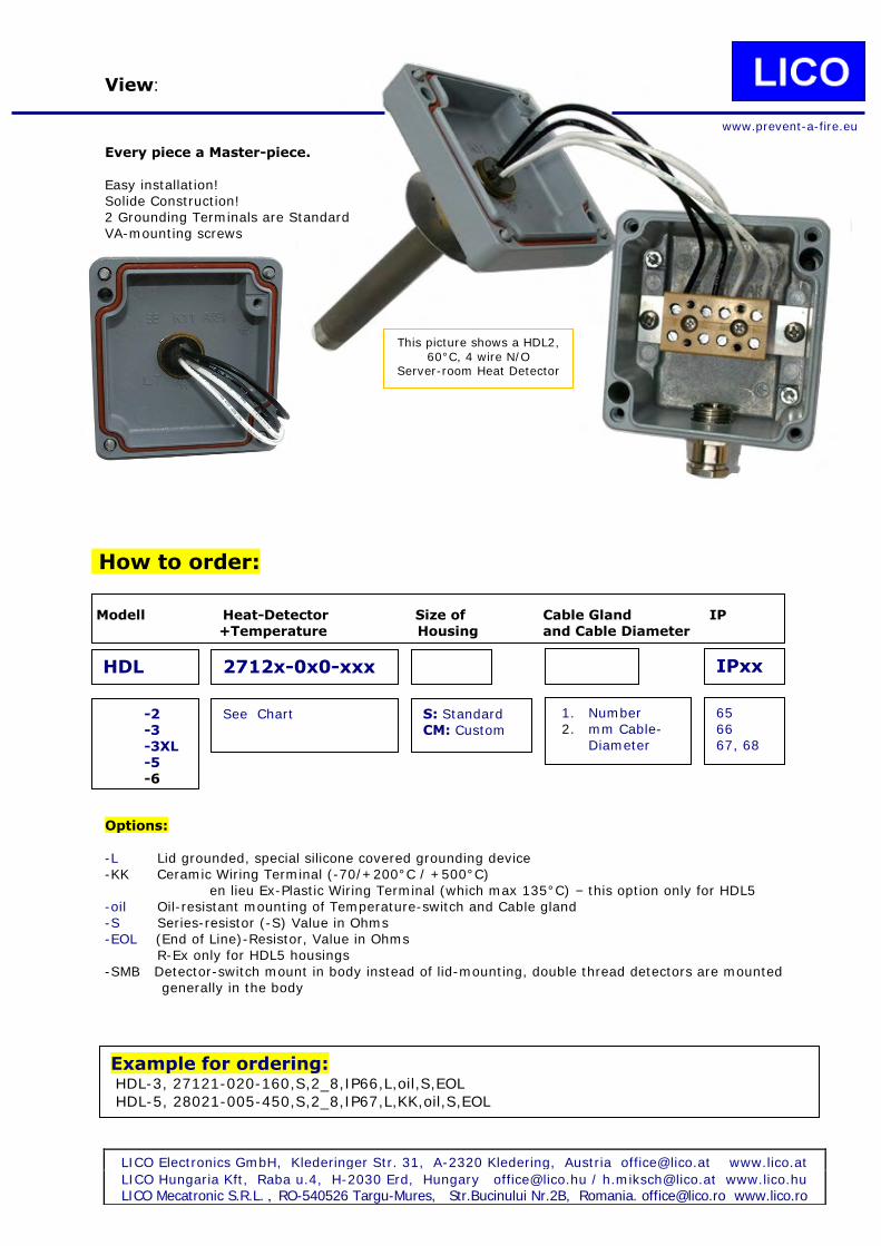
View:
Every piece a Master-piece.
Easy installation! Solide Construction! 2 Grounding Terminals are Standard VA-mounting screws
How to order: Modell Heat-Detector Size of Cable Gland IP
+Temperature Housing and Cable Diameter
Options:
-L Lid grounded, special silicone covered grounding device -KK Ceramic Wiring Terminal (-70/+200°C / +500°C)
en lieu Ex-Plastic Wiring Terminal (which max 135°C) – this option only for HDL5 -oil Oil-resistant mounting of Temperature-switch and Cable gland
-S Series-resistor (-S) Value in Ohms -EOL (End of Line)-Resistor, Value in Ohms R-Ex only for HDL5 housings
-SMB Detector-switch mount in body instead of lid-mounting, double thread detectors are mounted generally in the body
LICO Electronics GmbH, Klederinger Str. 31, A-2320 Kledering, Austria [email protected] www.lico.at
LICO Hungaria Kft, Raba u.4, H-2030 Erd, Hungary [email protected] / [email protected] www.lico.hu
LICO Mecatronic S.R.L. , RO-540526 Targu-Mures, Str.Bucinului Nr.2B, Romania. [email protected] www.lico.ro
HDL 2712x-0x0-xxx
S: Standard CM: Custom
1. Number 2. mm Cable-
Diameter
-2 -3 -3XL -5 -6
IPxx
65 66 67, 68
See Chart
Example for ordering: HDL-3, 27121-020-160,S,2_8,IP66,L,oil,S,EOL
HDL-5, 28021-005-450,S,2_8,IP67,L,KK,oil,S,EOL
This picture shows a HDL2, 60°C, 4 wire N/O
Server-room Heat Detector
www.prevent-a-fire.eu

DAF – DETECT-A-FIRE®
Available Standard Part numbers for DAF-switches:
Single Thread units:
DAF - Detect-a-Fire / Heat & Fire-Detector
Nominal
Switching-
temperature
Body Brass Body Stainless Body Brass Body Stainless
27120-000-140 27120-022-140 27121-000-140 27121-020-140 60°C / 140°F
27120-000-160 27120-022-160 27121-000-160 27121-020-160 71°C / 160°F
27120-000-190 27120-022-190 27121-000-190 27121-020-190 88°C / 190°F
27120-000-210 27120-022-210 27121-000-210 27121-020-210 99°C / 210°F
27120-000-225 27120-022-225 27121-000-225 27121-020-225 107°C / 225°F
27120-000-275 27120-022-275 27121-000-275 27121-020-275 135°C / 275°F
27120-000-325 27120-022-325 27121-000-325 27121-020-325 165°C / 325°F
27120-000-360 27120-022-360 27121-000-360 27121-020-360 187°C / 360°F
27120-000-450 27120-022-450 27121-000-450 27121-020-450 232°C / 450°F
27121-000-500 27121-020-500 260°C / 500°F
27121-000-600 27121-020-600 315°C / 600°F
27121-000-725 27121-020-725 385°C / 725°F
Sensor Housing Stainless Steel Sensor Housing Stainless Steel
2-wire unit
N/C, Opens at Rise
4-wire unit
N/O, Closes at Rise
Double Thread units:
DAF - Detect-a-Fire / Heat & Fire-Detector
Nominal
Switch-
temperature
Body Brass Body Stainless Body Brass Body Stainless
28020-003-140 28021-005-140 60°C / 140°F
28020-003-160 28021-005-160 71°C / 160°F
28020-003-190 28021-005-190 88°C / 190°F
28020-003-210 28021-005-210 99°C / 210°F
28020-003-225 28021-005-225 107°C / 225°F
28020-003-275 28021-005-275 135°C / 275°F
28020-003-325 28021-005-325 165°C / 325°F
28020-003-360 28021-005-360 187°C / 360°F
28020-003-450 28021-005-450 232°C / 450°F
28021-005-500 260°C / 500°F
28021-005-600 315°C / 600°F
28021-005-725 385°C / 725°F
Sensor Housing Stainless Steel Sensor Housing Stainless Steel
2-wire unit
N/C, Opens at Rise
4-wire unit
N/O, Closes at Rise
LICO Electronics GmbH, Klederinger Str. 31, A-2320 Kledering, Austria [email protected] www.lico.at
LICO Hungaria Kft, Raba u.4, H-2030 Erd, Hungary [email protected] / [email protected] www.lico.hu LICO Mecatronic S.R.L. RO-540526 Targu-Mures, Str.Bucinului Nr.2B Romania. [email protected] www.lico.ro
Brass & Stainless Steel or Fully Stainless steel N/C (2-Wire) opens at temperature rise or
N/O (4-Wire) closes at temperature rise
Fully Stainless steel N/C (2-Wire) opens at temperature rise or N/O (4-Wire) closes at temperature rise
Class 1, Group A requires fully Stainless-steel Fenwal DAF-versions !

ATEX-certified & special Switches
17343-124 -xxx, Temperatures: (100F), 140F - 725F, 60°C - 385°C Make in full stainless-steel Contacts N/O, close with increase of temperature Rating, 28VDC, 0,5A, 125VDC, 0,5A
Mounting: ¾”-14 NPT
CE/ATEX Approved for Group II,
Category 3 Gas, Type of protection:
“nC”
Unit is hermetically sealed.
Datasheet on request
17343-124 140F, 60°C
17343-124 325F, 165°C
17343-124 425F, 218°C
17343-124 600F, 315°C
17343-124 725F, 385°C
17343-113 -600, 17343-113 -950, 2 Temperatures: 600F, 950F = 315°C, 510°C
Flamesafe bis 2000°F/1082 °C for short periods
Make in full stainless-steel
Contacts N/O, close with increase of temperature
600°F UL Listed for
Class I Group A,B,C,D
Class II, Groups E,F,G,
For use in hazardous locations
CSA certified 600 + 950F,
overheat Detector in
hazardous locations.
Datasheet on request
Rating, 125VDC, 1A
Mounting: ¾”-14 NPT
17343-78-500, -725, -900
3 Temperatures: 600F - 950F = 315°C, 385°C, 482°C Flame safe until 2000°F/1082 °C for short periods 17343-78 500F, 315°C
17343-78 725F, 385°C
17343-78 900F, 482°C
Make in full stainless-steel
Contacts N/O, close with increase of temperature Rating: 28VDC, 3 A; 125VDC, 1A; 115VAC, 3A
Temperature: Field adjustable, Mounting: plate
Aircraft Overheat & Fire Detector
Datasheet on request

HDL1 – 200/220°C Heat Detector LICO – HDL4 – 385°C High-Temperature-Heat Detector
HDL-4 , 385/510°C-VHT,
the Very High-Temperature-solution based on Fenwal 116317 Housing and Fenwal Detect-A-Fire-Sensors
HDL-4 with 250°C ¾” NPT-Flextube or 385°C with solid ¾” NPT-Iron-tube and
even up to 510°C
For Details consult LICO 116317 Data-sheet. T-max 510°C with iron-tube and extra long Heat-Detector cables or 200°C with Std-Ceramic wiring block or 385°C with Special V2A Wiring-Block or 510C
with Fenwal Special Temperature switch ATEX and IP-rated High-temperature - tubes on request
HDL-1 Our Original Heavy Duty “Marine Grade” Fire-Detector-Box Available with Stainless-steel / Brass or Fully Stainless Temperature-Sensor-switch
Consult LICO HDL-1 Data-sheet WIG-Welded marine-Aluminum-Alloy Ultra-HD (Heavy-Duty)-Version Unit: IP67 / IP68
Seals: 200°C Composite or 220°C Silicone Seal, IP67/IP68 M20-Cable gland, 220°C Silicone, (Ex-certified until 100°C/140°C)
T-Max. 250°C ½” or ¾” Stainless-NPT-Flextube T-Max 385°C with solid ½” or ¾” NPT-Aluminum or iron-tube and extra long Heat-Detector cables or with HT-Ceramic wiring block.
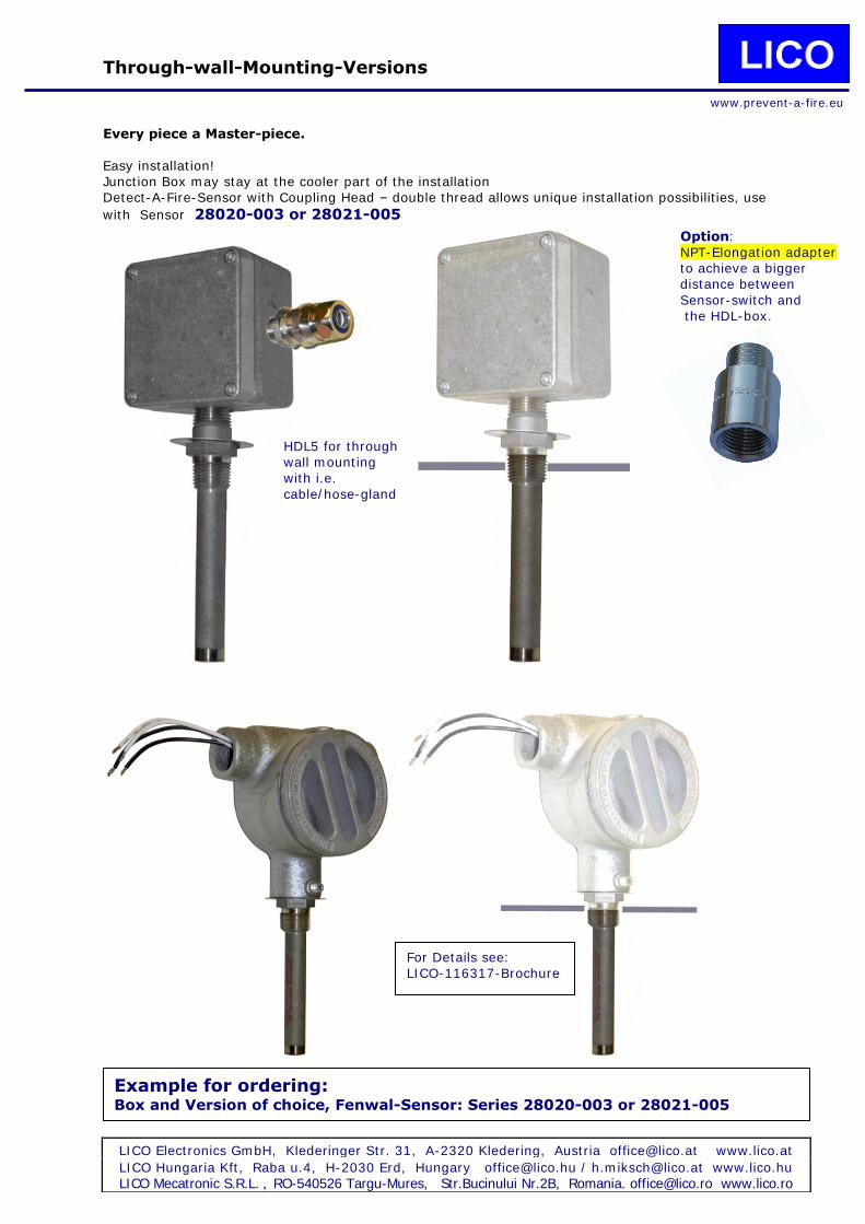
Through-wall-Mounting-Versions
Every piece a Master-piece.
Easy installation! Junction Box may stay at the cooler part of the installation Detect-A-Fire-Sensor with Coupling Head – double thread allows unique installation possibilities, use
with Sensor 28020-003 or 28021-005
LICO Electronics GmbH, Klederinger Str. 31, A-2320 Kledering, Austria [email protected] www.lico.at
LICO Hungaria Kft, Raba u.4, H-2030 Erd, Hungary [email protected] / [email protected] www.lico.hu
LICO Mecatronic S.R.L. , RO-540526 Targu-Mures, Str.Bucinului Nr.2B, Romania. [email protected] www.lico.ro
Example for ordering: Box and Version of choice, Fenwal-Sensor: Series 28020-003 or 28021-005
For Details see: LICO-116317-Brochure
HDL5 for through wall mounting with i.e.
cable/hose-gland
Option: NPT-Elongation adapter to achieve a bigger distance between
Sensor-switch and the HDL-box.
www.prevent-a-fire.eu

Grounding Cable & Adapter
LICO Electronics GmbH, Klederinger Str. 31, A-2320 Kledering, Austria [email protected] www.lico.at
LICO Hungaria Kft, Raba u.4, H-2030 Erd, Hungary [email protected] / [email protected] www.lico.hu
LICO Mecatronic S.R.L. , RO-540526 Targu-Mures, Str.Bucinului Nr.2B, Romania. [email protected] www.lico.ro
Example for ordering: Specify material, Stainless steel 316L or Aluminum
Option:
NPT-Elongation adapter to achieve a bigger distance between Sensor-switch and the HDL-box. Box-mounting side is DIN thread with mounting nut Mounting by special liquid thread lock, Operation suitable up to 250°C
Our standard and material shown: Stainless steel 316L
Sensing switch
Junction Box-side
www.prevent-a-fire.eu
Option: Grounding cable, # -L
Mounted inside the box to connect box and lid to avoid static charge during operation and opening. HT-silicone Copper-cable or HT-Silicone covered steel ball chain, massive construction.

Weld-in pod / Screw-in pod
A popular solution in gas, oil and chemical industry. Also widely used in hydraulics, frying and drying applications as well as in oven and heating controls. Easy installation! Drilling the hole and welding in the weld-in pod allows easy installation and safe service without contact to the tank media.
LICO Electronics GmbH, Klederinger Str. 31, A-2320 Kledering, Austria [email protected] www.lico.at
LICO Hungaria Kft, Raba u.4, H-2030 Erd, Hungary [email protected] / [email protected] www.lico.hu
LICO Mecatronic S.R.L. , RO-540526 Targu-Mures, Str.Bucinului Nr.2B, Romania. [email protected] www.lico.ro
For ordering: Please specify weld-in or screw-in type, material and shell thickness
Inside tank
Option: Stainless-steel NPT- Screw-in-adapter,
Outside & inside NPT-thread instead of outside weld-in. with or without hexagon
www.prevent-a-fire.eu

HDL3 - HDL5 - Variations
- Heat- & Fire Detector
LICO Electronics GmbH, Klederinger Str. 31, A-2320 Kledering, Austria [email protected] www.lico.at
LICO Hungaria Kft, Raba u.4, H-2030 Erd, Hungary [email protected] / [email protected] www.lico.hu
LICO Mecatronic S.R.L. RO-540526 Targu-Mures, Str.Bucinului Nr.2B Romania. [email protected] www.lico.ro
HDL-5-28000 The only HT,
Hochtemperature-HDL
for Ex-CL1 with 1 or 2
Cable- or Cable-Hose-Glands
HDL-5
For most simple mounting
and installation with 1 or 2 Cable or Cable–hose Glands
Fenwal-Sensor of
Choice
HDL-3, Main Data: T max: 135°C
Box: Alu Dimension of Bx: 80x80x57mm or with XL-Box: 125x80x57mm für armoured Cable
Cable Gland: 1 or 2 (optional) Ex-certified until 135°C: Cable Gland, Wiring Block, Box
HDL-5, Main Data: , T max: 220°C
Box: Alu , 135°C ATEX, plus 220°C HT-Silikone-seal
Dimension: 122x120x81mm
ATEX-Cable-Cable-Hose Gland: ie Cable 5,5-8 mm or according request, ATEX 135°C or 220°C
Wiring Block: Ceramic/Nickel/Stainless, ATEX Certifiable until 210°C: Wiring Block, T.max 500C
IP66 = Standard Optional IP67/68
www.prevent-a-fire.eu

The LICO Alarmpanel
You specifiy the function, we deliver right that.
You choose, we ship: Massive Aluminumhousing with Membrane-keyboard, dedicated programmed µController
1 oder 2 Inputs, N/O or N/C
9-30 VDC
Individual Printing of Keyboard possible
Integrated Wirebreak-control
Opt: Housing with Cabelglands or Flushmount
0, 4, 15, 23 mA Functional Currents
Output:
Alarm-LED
2 Outputs: 1 Output per Channel, switch only
www.prevent-a-fire.eu
Ask for the Alarmpanel data sheet!
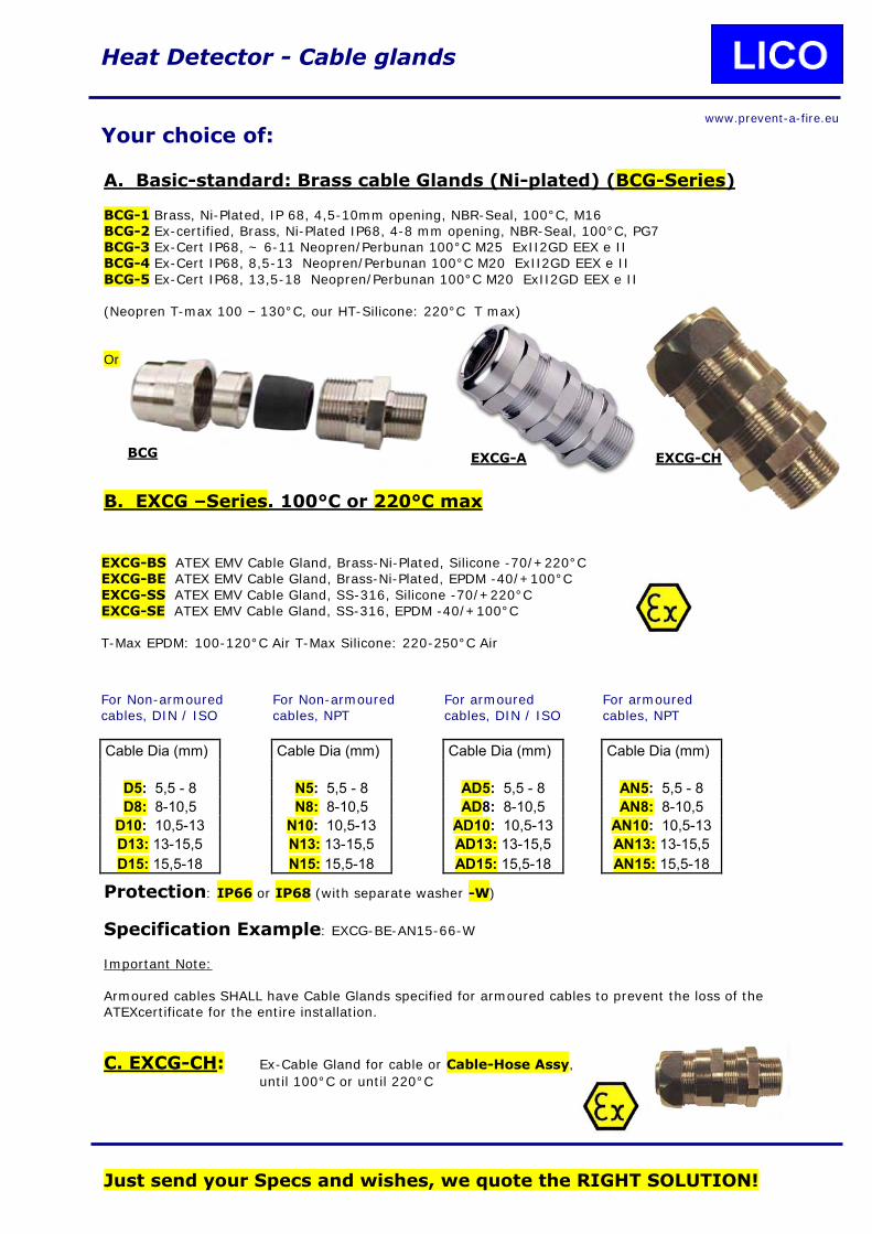
A. Basic-standard: Brass cable Glands (Ni-plated) (BCG-Series) BCG-1 Brass, Ni-Plated, IP 68, 4,5-10mm opening, NBR-Seal, 100°C, M16 BCG-2 Ex-certified, Brass, Ni-Plated IP68, 4-8 mm opening, NBR-Seal, 100°C, PG7 BCG-3 Ex-Cert IP68, ~ 6-11 Neopren/Perbunan 100°C M25 ExII2GD EEX e II BCG-4 Ex-Cert IP68, 8,5-13 Neopren/Perbunan 100°C M20 ExII2GD EEX e II
BCG-5 Ex-Cert IP68, 13,5-18 Neopren/Perbunan 100°C M20 ExII2GD EEX e II (Neopren T-max 100 – 130°C, our HT-Silicone: 220°C T max) Or
B. EXCG –Series. 100°C or 220°C max
Protection: IP66 or IP68 (with separate washer -W)
Specification Example: EXCG-BE-AN15-66-W
Important Note: Armoured cables SHALL have Cable Glands specified for armoured cables to prevent the loss of the ATEXcertificate for the entire installation.
C. EXCG-CH: Ex-Cable Gland for cable or Cable-Hose Assy,
until 100°C or until 220°C
Just send your Specs and wishes, we quote the RIGHT SOLUTION!
Heat Detector - Cable glands
Your choice of:
EXCG-BS ATEX EMV Cable Gland, Brass-Ni-Plated, Silicone -70/+220°C EXCG-BE ATEX EMV Cable Gland, Brass-Ni-Plated, EPDM -40/+100°C
EXCG-SS ATEX EMV Cable Gland, SS-316, Silicone -70/+220°C EXCG-SE ATEX EMV Cable Gland, SS-316, EPDM -40/+100°C T-Max EPDM: 100-120°C Air T-Max Silicone: 220-250°C Air
For armoured cables, DIN / ISO
Cable Dia (mm)
AD5: 5,5 - 8
AD8: 8-10,5
AD10: 10,5-13
AD13: 13-15,5
AD15: 15,5-18
For armoured cables, NPT
Cable Dia (mm)
AN5: 5,5 - 8
AN8: 8-10,5
AN10: 10,5-13
AN13: 13-15,5
AN15: 15,5-18
For Non-armoured cables, NPT
Cable Dia (mm)
N5: 5,5 - 8
N8: 8-10,5
N10: 10,5-13
N13: 13-15,5
N15: 15,5-18
For Non-armoured cables, DIN / ISO
Cable Dia (mm)
D5: 5,5 - 8
D8: 8-10,5
D10: 10,5-13
D13: 13-15,5
D15: 15,5-18
BCG EXCG-A EXCG-CH
www.prevent-a-fire.eu

Options:
R-„EX“
Elektrotechnik 5 W Former-Ex-conform- Resistors as
Series or End of Line Resistors (EOL) for Ex e Boxes T3 max 40°C, T 6 max 60°C (Ex-cert. expired, T max 125C, out-gasing may occur at higher Temperatures)
220°C “Ex-conform”-Resistors are in Design & Evaluation We are glad to receive your inquiry!
XL-Housing for HDL-3 (Ex) With 125x80x57 mm considerably bigger for convenient and
solid mounting of big Series- and EOL-Resistors
HDL-2-R, HDL-3-R, Separate R-Box for EOL or series resistors with one cable gland
Choice of of: HDL2-Box: 80°C or 100 °C HDL3-Box: 140°C, 140°C Ex, or 200°C HT HDL5-Box: with ceramic wiring blocks, 2-6 positions
Optional: Double Mounting-head-Sensor Fenwal Series 28000 For “through-wall-mounting”
Standard for Ex-versions ATEX-Certified Wiring Block, -50/+130°C, Ex e II
-50/+210°C, Ex e II 2, 3 , 4 or 5 poles
Wiring: 0,5 - 4 mm² VDE-approved Wiring Blocks:
Porcellain C111 glazed or Steatik C220 unglazed
2, 3 or 4 poles Wiring: 0,5-2,5 mm²/ 1,5-6 mm², 24A
T max: 350°C surface, 200°C brass-parts to avoid burn-out,
VDE- Ultra-High-Temperature-Wiring Blocks: Option: 2-pole 500°C-Wiring-Block-Version: All electrical parts are made entirely of V2A
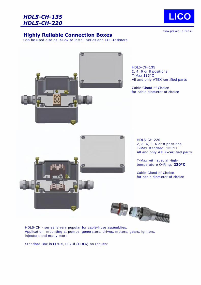
HDL5-CH-135
HDL5-CH-220
Highly Reliable Connection Boxes Can be used also as R-Box to install Series and EOL-resistors
www.prevent-a-fire.eu
HDL5-CH-135
2, 4, 6 or 8 positions
T-Max 135°C
All and only ATEX-certified parts
Cable Gland of Choice for cable diameter of choice
HDL5-CH-220
2, 3, 4, 5, 6 or 8 positions
T-Max standard: 135°C
All and only ATEX-certified parts
T-Max with special High-
temperature O-Ring: 220°C
Cable Gland of Choice
for cable diameter of choice
HDL5-CH - series is very popular for cable-hose assemblies.
Application: mounting at pumps, generators, drives, motors, gears, ignitors,
injectors and many more.
Standard Box is EEx-e, EEx-d (HDL6) on request
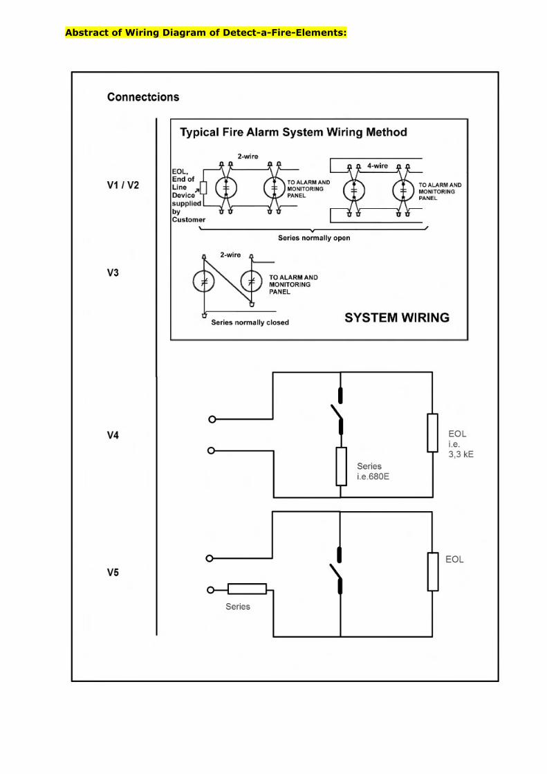
Abstract of Wiring Diagram of Detect-a-Fire-Elements:

NPT-threads:
National Pipe Thread Tapered Thread (NPT) is a U.S. standard for tapered threads used on threaded pipes and fittings. BSP is a British Pipe thread (see also Whitworth-threads)
Jointing threads: These are pipe threads where pressure-tightness is made through the mating of two threads together. Additional seal tapes or thread sealant compounds might be necessary for both NPT & BSP-
joints.
MIP: stands for Male Iron Pipe, or Male International Pipe, or MPT Male Pipe Thread. It is a term for pipe fittings.
FIP: stands for Female Iron Pipe, or Female International Pipe, or FPT. It is a term for pipe fittings that MIP fittings fit into.
Mating of NPT and BSP is not possible due to different cone angle, threads per inch, depth and pitch.
Das National Pipe Thread (NPT-Gewinde, NPT-Rohrgewinde) nach ASME/ANSI B1.20.1 ist eine US-
amerikanische Gewindenorm für selbstdichtende Rohrverschraubungen entsprechend der europäischen Anschauung..
Die Dichtung wird dadurch erreicht, dass die Gewinde kegelig angeordnet werden. Bei Zusammenschrauben konventioneller Rohrgewinde wird zusätzlich ein Dichtmittel (z. B. Teflonband, Hanf) zwischen die Gewinde gelegt. Im Gegensatz dazu benötigt das National Pipe Thread - Dryseal Form (NPTF-Gewinde, NPTF-Rohrgewinde) nach ASME/ANSI B1.20.3 primär kein Dichtmittel. Häufig werden jedoch flüssige Schraubendichtmittel oder Hanf oder Teflon zur Sicherung eingesetzt. Gelegentlich werden NPT-Gewinde auch als MPT (Male Pipe Thread) oder FPT (Female Pipe Thread) und auch als MIP (Male iron pipe) and FIP (Female iron pipe) bezeichnet.
Gegenüber dem Withworth-Gewinde, welches auch als British Standard Pipe (BSP) bekannt ist, sind die Durchmesser, Gangzahl (Steigung in Gängen pro Zoll, threads per inch) als auch Kegelwinkel leicht unterschiedlich, so dass die beiden Gewinde nicht miteinander verschraubbar sind.
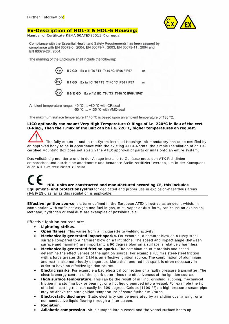
Further Information:
Ex-Description of HDL-3 & HDL-5 Housing: Number of Certificate KEMA 00ATEX85011 X or equal
LICO optionally can mount Very High Temperature O-Rings of i.e. 220°C in lieu of the cert.
O-Ring., Then the T.max of the unit can be i.e. 220°C, higher temperatures on request.
The fully mounted and in the Sytem installed Housing/unit mandatory has to be certified by an approved body to be in accordance with the existing ATEX-Norms, the simple Installation of an EX-
certified Mounting Box does not stretch the ATEX approval of parts or units onto an entire system. Das vollständig montierte und in der Anlage installierte Gehäuse muss den ATX Richtlinien entsprechen und durch eine anerkannte und benannte Stelle zertifiziert werden, um in der Konsquenz auch ATEX-mitzertifiziert zu sein!
HDL-units are constructed and manufactured according CE, this includes Equipment- and protectionsystms for dedicated and proper use in explosion-hazardous areas (94/9/EG), as far as this regulation is applicable.
Effective ignition source is a term defined in the European ATEX directive as an event which, in
combination with sufficient oxygen and fuel in gas, mist, vapor or dust form, can cause an explosion. Methane, hydrogen or coal dust are examples of possible fuels.
Effective ignition sources are:
Lightning strikes.
Open flames. This varies from a lit cigarette to welding activity.
Mechanically generated impact sparks. For example, a hammer blow on a rusty steel
surface compared to a hammer blow on a flint stone. The speed and impact angle (between surface and hammer) are important; a 90 degree blow on a surface is relatively harmless.
Mechanically generated friction sparks. The combination of materials and speed
determine the effectiveness of the ignition source. For example 4.5 m/s steel-steel friction with a force greater than 2 kN is an effective ignition source. The combination of aluminium and rust is also notoriously dangerous. More than one red hot spark is often necessary in order to have an effective ignition source.
Electric sparks. For example a bad electrical connection or a faulty pressure transmitter. The
electric energy content of the spark determines the effectiveness of the ignition source.
High surface temperature. This can be the result of milling, grinding, rubbing, mechanical friction in a stuffing box or bearing, or a hot liquid pumped into a vessel. For example the tip
of a lathe cutting tool can easily be 600 degrees Celsius (1100 °F); a high pressure steam pipe may be above the autoignition temperature of some fuel/air mixtures.
Electrostatic discharge. Static electricity can be generated by air sliding over a wing, or a non-conductive liquid flowing through a filter screen.
Radiation.
Adiabatic compression. Air is pumped into a vessel and the vessel surface heats up.
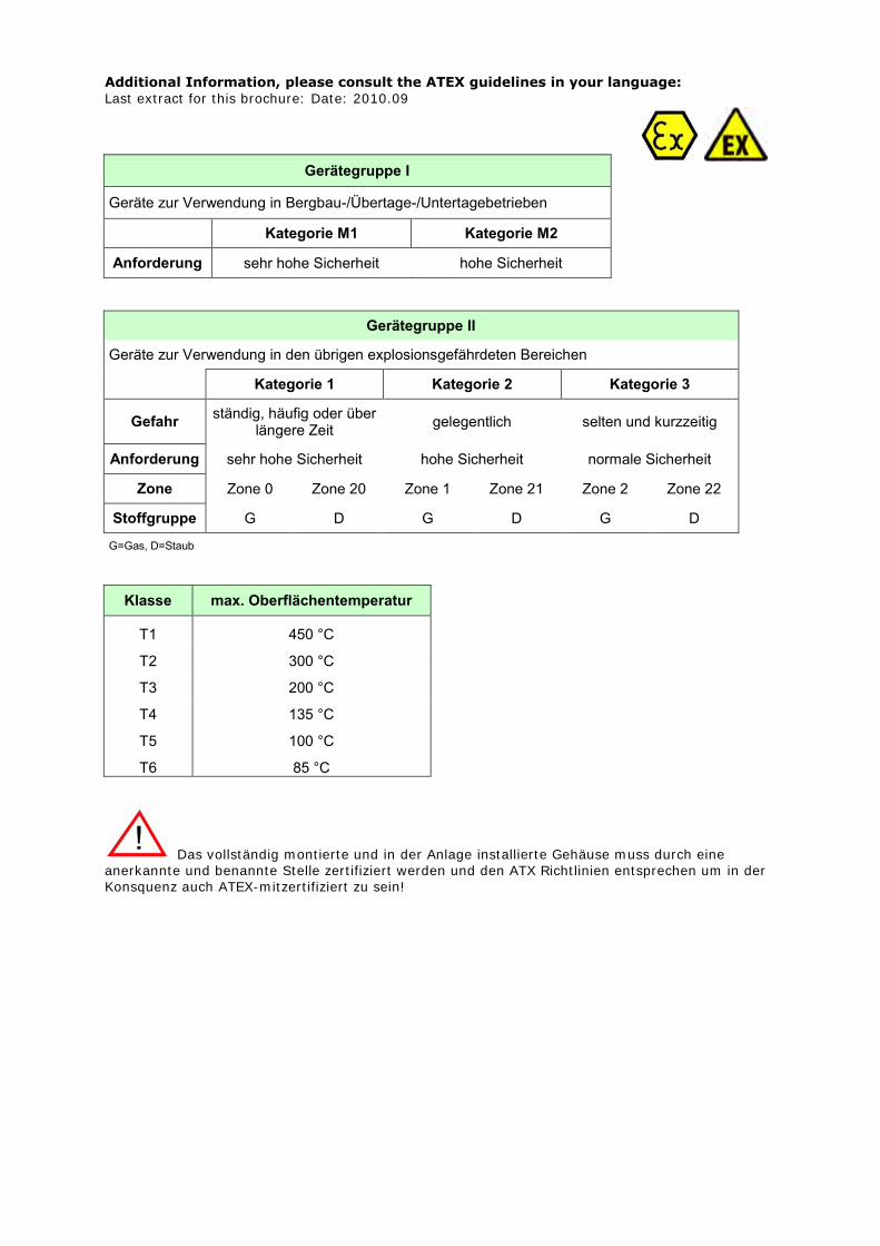
Additional Information, please consult the ATEX guidelines in your language:
Last extract for this brochure: Date: 2010.09
Gerätegruppe I
Geräte zur Verwendung in Bergbau-/Übertage-/Untertagebetrieben
Kategorie M1 Kategorie M2
Anforderung sehr hohe Sicherheit hohe Sicherheit
Gerätegruppe II
Geräte zur Verwendung in den übrigen explosionsgefährdeten Bereichen
Kategorie 1 Kategorie 2 Kategorie 3
Gefahr ständig, häufig oder über
längere Zeit gelegentlich selten und kurzzeitig
Anforderung sehr hohe Sicherheit hohe Sicherheit normale Sicherheit
Zone Zone 0 Zone 20 Zone 1 Zone 21 Zone 2 Zone 22
Stoffgruppe G D G D G D
G=Gas, D=Staub
Klasse max. Oberflächentemperatur
T1 450 °C
T2 300 °C
T3 200 °C
T4 135 °C
T5 100 °C
T6 85 °C
Das vollständig montierte und in der Anlage installierte Gehäuse muss durch eine anerkannte und benannte Stelle zertifiziert werden und den ATX Richtlinien entsprechen um in der Konsquenz auch ATEX-mitzertifiziert zu sein!
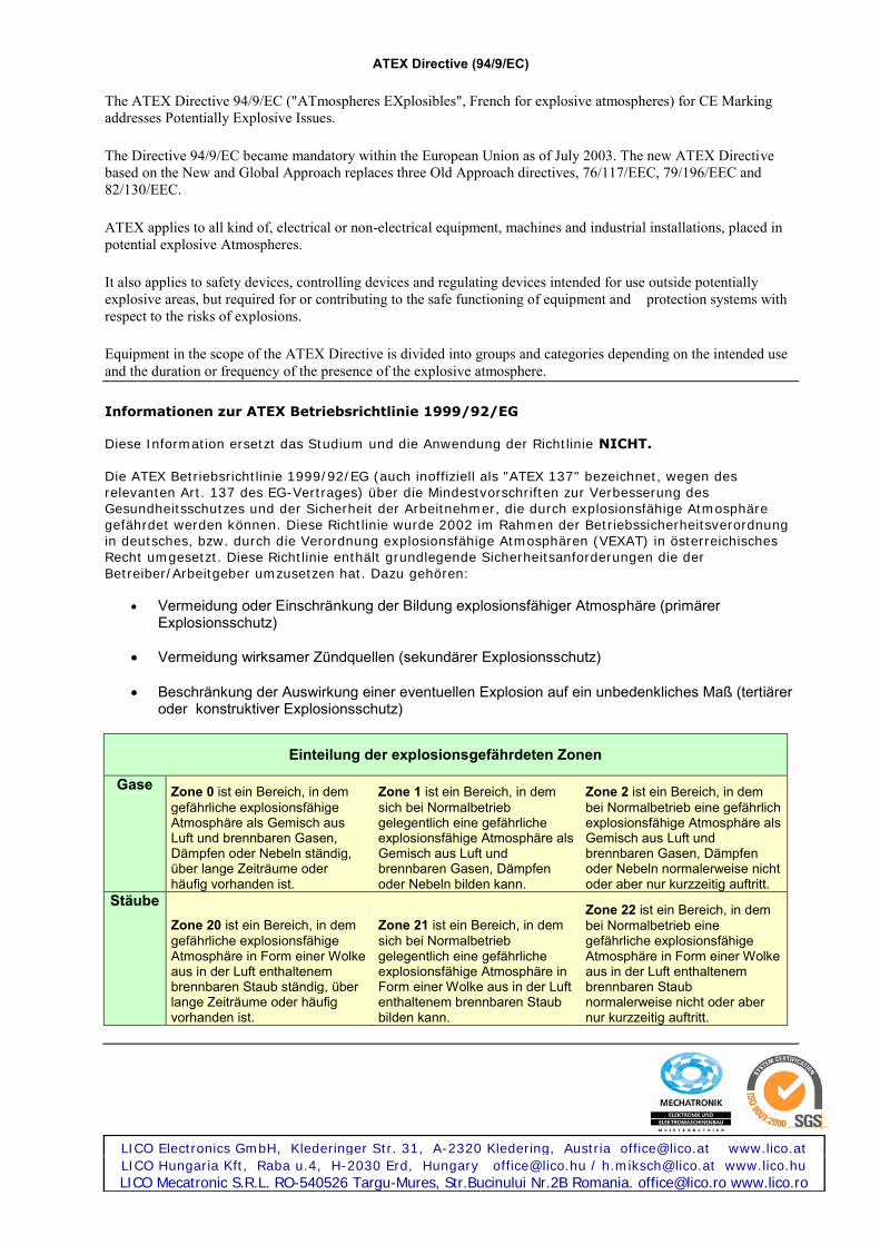
ATEX Directive (94/9/EC)
The ATEX Directive 94/9/EC ("ATmospheres EXplosibles", French for explosive atmospheres) for CE Marking
addresses Potentially Explosive Issues.
The Directive 94/9/EC became mandatory within the European Union as of July 2003. The new ATEX Directive
based on the New and Global Approach replaces three Old Approach directives, 76/117/EEC, 79/196/EEC and
82/130/EEC.
ATEX applies to all kind of, electrical or non-electrical equipment, machines and industrial installations, placed in
potential explosive Atmospheres.
It also applies to safety devices, controlling devices and regulating devices intended for use outside potentially
explosive areas, but required for or contributing to the safe functioning of equipment and protection systems with
respect to the risks of explosions.
Equipment in the scope of the ATEX Directive is divided into groups and categories depending on the intended use
and the duration or frequency of the presence of the explosive atmosphere.
Informationen zur ATEX Betriebsrichtlinie 1999/92/EG Diese Information ersetzt das Studium und die Anwendung der Richtlinie NICHT.
Die ATEX Betriebsrichtlinie 1999/92/EG (auch inoffiziell als "ATEX 137" bezeichnet, wegen des relevanten Art. 137 des EG-Vertrages) über die Mindestvorschriften zur Verbesserung des Gesundheitsschutzes und der Sicherheit der Arbeitnehmer, die durch explosionsfähige Atmosphäre gefährdet werden können. Diese Richtlinie wurde 2002 im Rahmen der Betriebssicherheitsverordnung in deutsches, bzw. durch die Verordnung explosionsfähige Atmosphären (VEXAT) in österreichisches Recht umgesetzt. Diese Richtlinie enthält grundlegende Sicherheitsanforderungen die der
Betreiber/Arbeitgeber umzusetzen hat. Dazu gehören:
Vermeidung oder Einschränkung der Bildung explosionsfähiger Atmosphäre (primärer Explosionsschutz)
Vermeidung wirksamer Zündquellen (sekundärer Explosionsschutz)
Beschränkung der Auswirkung einer eventuellen Explosion auf ein unbedenkliches Maß (tertiärer oder konstruktiver Explosionsschutz)
Einteilung der explosionsgefährdeten Zonen
Gase Zone 0 ist ein Bereich, in dem
gefährliche explosionsfähige Atmosphäre als Gemisch aus Luft und brennbaren Gasen, Dämpfen oder Nebeln ständig, über lange Zeiträume oder häufig vorhanden ist.
Zone 1 ist ein Bereich, in dem
sich bei Normalbetrieb gelegentlich eine gefährliche explosionsfähige Atmosphäre als Gemisch aus Luft und brennbaren Gasen, Dämpfen oder Nebeln bilden kann.
Zone 2 ist ein Bereich, in dem
bei Normalbetrieb eine gefährlich explosionsfähige Atmosphäre als Gemisch aus Luft und brennbaren Gasen, Dämpfen oder Nebeln normalerweise nicht oder aber nur kurzzeitig auftritt.
Stäube
Zone 20 ist ein Bereich, in dem
gefährliche explosionsfähige Atmosphäre in Form einer Wolke aus in der Luft enthaltenem brennbaren Staub ständig, über lange Zeiträume oder häufig vorhanden ist.
Zone 21 ist ein Bereich, in dem
sich bei Normalbetrieb gelegentlich eine gefährliche explosionsfähige Atmosphäre in Form einer Wolke aus in der Luft enthaltenem brennbaren Staub bilden kann.
Zone 22 ist ein Bereich, in dem
bei Normalbetrieb eine gefährliche explosionsfähige Atmosphäre in Form einer Wolke aus in der Luft enthaltenem brennbaren Staub normalerweise nicht oder aber nur kurzzeitig auftritt.
LICO Electronics GmbH, Klederinger Str. 31, A-2320 Kledering, Austria [email protected] www.lico.at
LICO Hungaria Kft, Raba u.4, H-2030 Erd, Hungary [email protected] / [email protected] www.lico.hu
LICO Mecatronic S.R.L. RO-540526 Targu-Mures, Str.Bucinului Nr.2B Romania. [email protected] www.lico.ro

IP Code (Ingress Protection)
Solids, first digit
The first digit indicates the level of protection that the enclosure provides against access to hazardous parts (e.g., electrical conductors, moving parts) and the ingress of solid foreign objects.
Level Object size protected against
Effective against
0 — No protection against contact and ingress of objects
1 >50 mm
Any large surface of the body, such as the back of a hand, but no protection against deliberate contact with a body part
2 >12.5 mm Fingers or similar objects 3 >2.5 mm Tools, thick wires, etc. 4 >1 mm Most wires, screws, etc.
5
Dust protected
Ingress of dust is not entirely prevented, but it must not enter in sufficient quantity to interfere with the satisfactory operation of the equipment; complete protection against contact
6 Dust tight No ingress of dust; complete protection against contact
Liquids, second digit Protection of the equipment inside the enclosure against harmful ingress of water.
Level
Protected against
Testing for Details
0 Not protected — —
1
Dripping water Dripping water (vertically falling drops) shall have no harmful effect.
Test duration: 10 minutes
Water equivalent to 1mm rainfall per minute
2 Dripping water when tilted up to 15°
Vertically dripping water shall have no harmful effect when the enclosure is tilted at an angle up to 15° from its normal position.
Test duration: 10 minutes
Water equivalent to 3mm rainfall per minute
3
Spraying water
Water falling as a spray at any angle up to 60° from the vertical shall have no harmful effect.
Test duration: 5 minutes
Water volume: 0.7 litres per minute
Pressure: 80–100 kN/m²
4
Splashing water
Water splashing against the enclosure from any direction shall have no harmful effect.
Test duration: 5 minutes
Water volume: 10 litres per minute
Pressure: 80–100 kN/m²
5
Water jets
Water projected by a nozzle (6.3mm) against enclosure from any direction shall have no harmful effects.
Test duration: at least 3 minutes
Water volume: 12.5 litres per minute
Pressure: 30 kN/m² at distance of 3m
6
Powerful water jets
Water projected in powerful jets (12.5mm nozzle) against the enclosure from any direction shall have no harmful effects.
Test duration: at least 3 minutes
Water volume: 100 litres per minute
Pressure: 100 kN/m² at distance of 3m
7 Immersion up to 1 m
Ingress of water in harmful quantity shall not be possible when the enclosure is immersed in water under defined conditions of pressure and time (up to 1 m of submersion).
Test duration: 30 minutes
Immersion at depth of 1m
8 Immersion beyond 1 m
The equipment is suitable for continuous immersion in water under
Test duration: continuous immersion in water

conditions which shall be specified by the manufacturer. Normally, this will mean that the equipment is hermetically sealed. However, with certain types of equipment, it can mean that water can enter but only in such a manner that it produces no harmful effects.
Depth specified by manufacturer
IP69K (Colloquially: Kärcher Safe)
German standard DIN 40050-9 extends the IEC 60529 rating system described above with an IP69K rating for high-pressure, high-temperature wash-down applications.[5] Such enclosures must not only be dust tight (IP6X), but also able to withstand high-pressure and steam cleaning.
The test specifies a spray nozzle that is fed with 80°C water at 8–10MPa (80–100bar) and a flow rate of 14–16L/min. The nozzle is held 10–15 cm from the tested device at angles of 0°, 40°, 60° and 90° for 30s each. The test device sits on a turntable that rotates once every 12s (5rpm).
The IP69K test specification was initially developed for road vehicles, especially those that need regular intensive cleaning (dump trucks, cement mixers, etc.), but also finds use in other areas (e.g., food industry, car wash centres).

CFD – Continuous Fire Detection The High-Temperature Sensing Element
The solution for Aircraft & Industry Overheat (OVHT) & Fire-alarm
MERKMALE Wiedereinschaltend soferne 1.100°C
nicht überschritten wurden,
wartungsfrei
Solide & robust -
widersteht Schock und Vibration
vielseitig einsetzbar – verschiedene
Schaltemperaturen, auch
untereinander kombinierbar
Dauerhaft –
° Langlebige Inconel Konstruktion
Wirtschaftlich –
° Deckt auch große Flächen ab,
° Sauber zu installieren
Das Innenleben des Sensorkabels ist
hermetisch in Inconel und Keramik
isoliert
Besonders Korrosionsbeständig
Alterungsbeständig
Extrem geringes Gewicht
APPLICATION Schutz von
Transformatoren und Schaltanlagen
Superheizanlagen
Nuclear engineering
Sprühtrockner
Gasturbinen
Ventilations Filter Bänke
Industrielle Wärme/Hitze-Trocker mit
Transportsystem für Pulver, Fasern,
Papier, Pulpe, Granulate, Schnitzel
etc.
Industrielle Trommeltrockner
Marine Motorräume, Antriebe
Große mechanische Antriebe
Große Kompressorstationen
Abgasanlagen/Abgassysteme
Hochtemperatur-Wärmetauscher
REFERENCES
Kidde Aerospace bezw Kidde Technologies Inc ist der Weltmarktführer im Bereich von
Überhitzungsschutz und Brandverhütung im Bereich von zivilen und militärischen Fluggerät. Kidde Aerospace schafft den Schutz für jede gefährliche Triebwerks-Situation und ist laut Eigenangabe die einzige Quelle für entsprechenden Schutz vor Feuer in Fluggeräten.
Auf der Erde werden weltweit industrielle Prozesse und Anlagen vor Überhitzung, Feuer oder Gas- und Staub- Explosionen geschützt.
Auszug aus einem Gerichtsurteil: Es entspricht der Lebenserfahrung, dass mit der Entstehung eines Brandes praktisch jederzeit gerechnet werden muss. Der Umstand, dass in vielen Gebäuden jahrzehntelang kein Brand ausbricht, beweist nicht, dass keine Gefahr besteht, sondern stellt für die Betroffenen einen Glücksfall dar, mit dessen Ende jederzeit gerechnet werden muss."
The Sensing Element The Fenwal sensing element consists of a small (.089 inchOD), lightweight, flexible Inconel
tube with a nickel wirecenter conductor. The tube is packed with an insulation-impregnated special salt compound and is hermetically sealed. The picture above shows the sensing element with standard-connectors.
DETECT HEAT & OVERHEAT AND PREVENT A FIRE Entsprechend der Schutzart, der Fläche und des
Schutzniveaus finden Sie bei LICO die richtige Lösung zur Vermeidung von Industriebrand.
ADVANTAGE Sehr schneller «Schalter»
Extrem zuverlässig
Höchste MTBF
Fehlalarm konstruktiv nicht möglich
Geringstes Gewicht

DESCRIPTION:
Die Eigenschaften des Sensorkabels:
Völlig wasserdicht korrosionsfest
schock und vibrationssicher klärt Überhitzung binnen
weniger Sekunden Hitzefest bis ~1.100°C
Damit ist das Sensorkabel seit über
50 Jahren der Industriestandard das Herz vieler Überhitzungsschutz- und Brandschutzsysteme.
Bei zig-tausenden Installationen werden diese Systeme entweder als Überhitzungsschutz eingesetzt, also als ALARM-Einrichtung und oder als Einrichtung zur hitzereduzierenden Aktion, zB Abschalten der
Anlage) oder bei der Feuerlöschung als auslösende Einrichtung um das Löschmittel freizusetzen. In vielen Fällen werden auch kombinierte Funktionen wie systemabschaltender Überhitzungsschutz UND Auslösen der Löscheinrichtung eingebaut.
STANDARD DATA: Alarm Temperaturen: 124°C, 154°C, 204°C, 302°C, 407°C, höhere Schaltpunkte nach technischer Klärung
T max reversibel: bis max. 1100°C
Abmessungen: Kabelsegmentlängen: 0,46 m – 4,60 m in 2,5 cm Teilungen
Max. Länge von Kabelsystemen: ~120m Längere Konfigurationen auf Anfrage Kabeldurchmesser: nur 2,25 mm
FUNCTION: Der Inconel-Röhre ist mit einem chemisch behandelten eutektischen Salz gefüllt. Unter normalen Umständen ist der Widerstand / Leitfähigkeit des dotierten Salzes so hoch, daß es zu „keinem“ Stromfluss kommt. Anm: der Stromfluß ist extrem gering) Die Eigenschaft des Salzes ist es, bei
Erreichen der Nominaltemperatur den Widerstand abzusenken und damit leitend zu werden. Damit werden der Innenleiter mit dem Mantel leitend verbunden und genau auf den dotierten Nominalwert wird das Alarmpanel aktiviert..

LICO Electronics GmbH, Klederinger Str. 31, A-2320 Kledering, Austria [email protected] www.lico.at
LICO Hungaria Kft, Raba u.4, H-2030 Erd, Hungary [email protected] / [email protected] www.lico.hu
LICO Mecatronic S.R.L. RO-540526 Targu-Mures, Str.Bucinului Nr.2B Romania. [email protected] www.lico.ro
FUNCTION:
Bei einem typischen OVHT/Feueralarmsystem gibt es üblicherweise 2 identische Kabelschleifen.
Diese können je nach Planung & Layout entweder in Serie oder parallel geschalten werden. Die Auslegung kann sich wie folgt darstellen: Beide Schleifen für Überhitzung oder eine Schleife für Überhitzung, die andere Schleife für Feuer. Somit kann klar und ohne den Einsatz von weiterer Elektronik bei Erreichen der Nominaltemperatur = Schalttemperatur der Alarm geschalten oder auch zB eine Löscheinrichtung oder Kühlung eingeschalten werden. Üblicherweise muß bei elektronischen Lösungen eben mehr oder weniger Elektronik zum Einsatz
kommen. Nicht nur, daß dies die Fehleranfälligkeit erhöht, eine elektronische Lösung gestattet auch nicht mehr, daß der auslösende Schalter selbst den Alarm auslöst oder zB ein Löschventil öffnet. Bei fest eingestellten Punktdetektoren muss erst an dem jeweils vorgegebenen Punkt die Alarmtemperatur erreicht um den Schalter auszulösen. Ist die Hitzequelle zwischen 2 Schaltern kann es zu einem entsprechenden Zeitverzug kommen, bis der eine oder andere Schalter auslöst. Das HT-CFD – Inconel-Kabel wird bei Erreichen der Nominaltemperatur systeminherent AN JEDER
BELIEBIGEN STELLE leitend und damit „schalten“. Diese technische Lösung gestattet damit beim allerersten Auftreten von Überhitzung die Gefahr bannen zu können, noch bevor es zu einem Brand
kommt.
PART NUMBER: Length: 45 cm – 450 cm (18-180 Zoll), es können bis über 100m Kabel gleicher oder
verschiedener Temperaturen in Serie geschalten werden
Temperatures: 124°C, 154°C, 204°C, 302°C, 407°C (255ºF, 310ºF, 400ºF, 575ºF, 765ºF) Höhere Temperaturen für Spezialanwendungen auf Anfrage.
Partnumber: 35XXX-2-XXX Beispiel: 35100-2-154: ein 1,0 m (40“) langes Kabel mit einer Schalttemperatur von 154°C (310°F) Beispiel: 35450-2-204: ein 4,5 m (180“) langes Kabel mit einer Schalttemperatur von 204°C (400°F) Beispiel: 35050-2-407: ein 50 cm (20“) langes Kabel mit einer Schalttemperatur von 407°C (765°F) To reach for example a length of 41 meters, 9 pcs sensing elements are requested.
Temperatur in °C
Länge des Kabels in cm
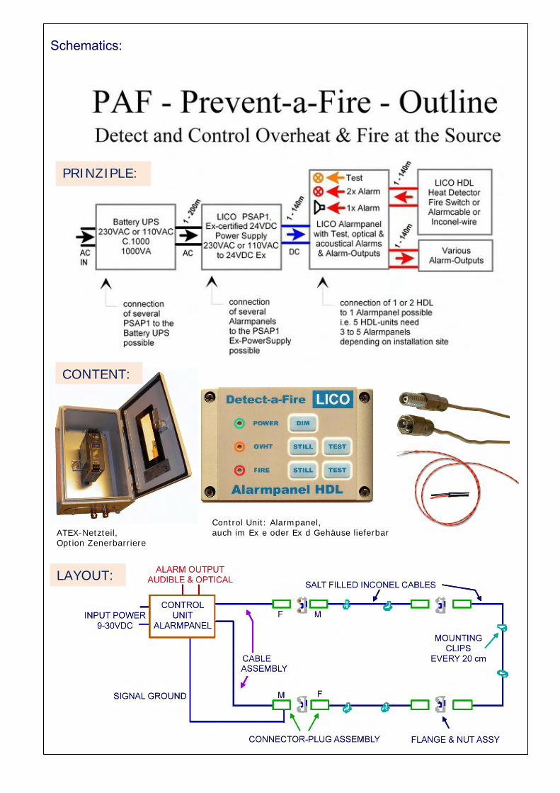
Schematics:
ATEX-Netzteil, Option Zenerbarriere
Control Unit: Alarmpanel, auch im Ex e oder Ex d Gehäuse lieferbar
LAYOUT:
CONTENT:
PRINZIPLE:

Connectors and Mounting material 1/2: Screw-in Connector Plug Assemblies Loose Cable Assemblies:
Cable assemblies are available in male and female thread configuration. They may be used singly to connect the sensing element termination to the control unit or in combination to connect sensing element sections through volumes not monitored by the elements.
Connector assemblies are available in male and female thread configuration to accommodate either end of the sensing element. The plug thread facilitates connection to a standard conduit box like the HDL-Conn-box.

Connectors and Mounting material 2/2: Sensing Element The Fenwal sensing element consists of a small 2,26 mm diameter (.089 inch OD), lightweight, flexible Inconel tube with a nickel wirecenter conductor. The tube is packed with insulation impregnated with a special salt compound and is hermetically sealed. The picture below shows the sensing element with standard m + f connectors. Flange and Nut Assemblies: Flange and nut assemblies are used to support the connection of two sensing elements. They are used to support and separate the elements from the structure or as a bulkhead feed through supports. Flange and nut assemblies may be surface or bulkhead mounted.

The Alarmsystem: Content:
1. (Industrial-Server-USV) 2. ATEX-certified 24VDC Power Supply 3. Safetybarriere
4. LICO Alarmpanel: The Alarmpanel provides the supply and control for action, stand-by, cable break Alarm, short-cut and test
The Standardkonfiguration offers 2 Inputs. The Output is realized by 2 integrated optical and audible Alarms. . External Outputs are 2 each for Alarm 1 + 2, audible and optical Alarm (N(O & N/C –Outputs allow connection to practically ANY alarm-system on the market. ) Versions: Build in panel (with O-Ring or Stand-alone ( wall-mount with cable glands) The Layout usually is custom-made.
5. CFD-cables

ALARMLINE DIGITAL
Comprises a twin-conductor "switching" cable with temperature-sensitive insulation
protected by a special sheath. It operates by melting of the insulation between the conductors
at a pre-determined temperature. This creates a short circuit which is detected by a simple
electrical device, which in turn provides a fire alarm signal. Fault conditions are detected by
continuous monitoring for an open circuit state.
ALARMLINE ANALOGUE
Consists of a four-conductor cable surrounded by an outer sheath of PVC. A change in
temperature produces a change in resistance, which is monitored by an Alarmline Control
Unit, which in turn actuates an alarm signal at a predetermined level. The cable is
continuously monitored for open and short circuit fault conditions. It detects either a
localised hot spot or a lower level of temperature increrase over the entire length. It is
recoverable after operation.

ALARMLINE DIGITAL, LHS Comprises a twin-conductor "switching" cable with temperature-sensitive insulation
protected by a special sheath. It operates by melting of the insulation between the
conductors at a pre-determined temperature. This creates a short circuit which is detected by
a simple electrical device, which in turn provides a fire alarm signal. Fault conditions are
detected by continuous monitoring for an open circuit state Cable control is permanent.
A safety barrier may be used in Ex-areas.
Main applications: Tank roofs, Dryers
Evaluation unit: LICO Alarmpanel
Fixed Temperatures:
68°C, Suitable for in-door & out-door
85°C Suitable for in-door & out-door
105°C
174°C
227°C
Minimum lentgh: 100 m
ALARMLINE ANALOG 4-wire system: - Consists of a four-conductor cable surrounded by an outer sheath of PVC.
A change in temperature produces a change in resistance, which is monitored by an
Alarmline Control Unit, which in turn actuates an alarm signal at a predetermined level. The
cable is continuously monitored for open and short circuit fault conditions. It detects either a
localised hot spot or a lower level of temperature increrase over the entire length. It is
recoverable after operation.
Main applications: Car parks, Garages, Cable trays, Shredders,
Escalators,,moving walkways, Building spaces, Melting operations, Tunnels
A safety barrier may be used in Ex-areas.
Evaluation Unit: LWM-1
Switching cable Temperatures:up to max 105°C,
Versions:
Sensor cable blue, Basis, staub und wasserbeständig
Sensor cable black, Nyloncovered, acid save
Sensor cable black, with steel-braid coverage, acid save,
mechanisch belastbar
Connectors & blinds
www.prevent-a-fire.eu
Related Documents


![New mixer de gaze mecatronic. - draeger.com · 2020. 1. 20. · mixer de gaze mecatronic. d-12642-2018 8wlol]duhfrqyhqdelofxlqwhuid lqrphqfodwxuvwdqgdugl]dwh lpsohphqwdwhvqqxphurdvh](https://static.cupdf.com/doc/110x72/6055369978844c692920c6d2/new-mixer-de-gaze-mecatronic-2020-1-20-mixer-de-gaze-mecatronic-d-12642-2018.jpg)