Status of 3.9 GHz LLRF FLASH Upgrade 2009/2010 Seminar Markus Hoffmann for the 3.9 GHz Team [email protected] http://www.desy.de/DESY – Deutsches Elektronen-Synchrotron Hamburg, GERMANY 18. Januar 2010 Inhaltsverzeichnis 1 Contents 3 2 Third Harmonic System 3 3 3.9 GHz Cavity 4 4 FLASH Module ACC39 4 5 Global Requirements 5 6 Bunch Compressor 5 7 Requirements on RF control (Injector) 6 8 Req. on 3rd Harmonic System (Injector) 6 9 RF Field Control 7 10 3.9 GHz Challenges 7 11 P-Controller Gain Limitation 8 12 Realization 8 13 SIMCON DSP 9 1

Welcome message from author
This document is posted to help you gain knowledge. Please leave a comment to let me know what you think about it! Share it to your friends and learn new things together.
Transcript

Status of 3.9 GHz LLRFFLASH Upgrade 2009/2010 Seminar
Markus Hoffmannfor the 3.9 GHz Team
[email protected]://www.desy.de/DESY– Deutsches Elektronen-Synchrotron
Hamburg, GERMANY
18. Januar 2010
Inhaltsverzeichnis
1 Contents 3
2 Third Harmonic System 3
3 3.9 GHz Cavity 4
4 FLASH Module ACC39 4
5 Global Requirements 5
6 Bunch Compressor 5
7 Requirements on RF control (Injector) 6
8 Req. on 3rd Harmonic System (Injector) 6
9 RF Field Control 7
10 3.9 GHz Challenges 7
11 P-Controller Gain Limitation 8
12 Realization 8
13 SIMCON DSP 9
1

Inhaltsverzeichnis
14 Hardware used in CMTB 9
15 3.9 GHz Converter Box 10
16 3.9 GHz Downconverter (IF=54MHz) 10
17 The Controller Algorithm 11
18 New Controller Algorithm 11
19 Software 12
20 User-Interface 12
21 Performance 13
22 Measurements 13
23 The Pulse 14
24 The Pulse 15
25 The Pulse 15
26 Analog Signal Check 16
27 Analog Signal Check 16
28 Cross-Talk 16
29 Loop Performance 17
30 Performance 18
31 Done? 18
32 Loaded Q 19
33 Detuning 19
34 Lorentz-Force-Detuning 20
35 Long Term Stability 20
36 Status 21
37 Status (2) 21
2

1 Contents
38 To Be Done 22
1 Contents
nopic1. The Third Harmonic System
ffl ACC39
2. Field Controller
ffl Requirements & Limitations
ffl System Overview: Hardware, Software, Firmware
ffl The new Controller Algorithm
3. Measurements
ffl Loop performance
ffl Loaded-Q, Detuning
ffl Long-term Stability
4. Status & Outlook
2 Third Harmonic System
3.9 GHz
4 cavities per module
TESLA type cavities have been scaled down in size to fit the 3.9 GHz.All auxiliaries like coupler, HOM coupler, frequency tuner, etc..., are scaled as well.Most of this work was done by H.Edwards et al. / FNAL.
• To improveBunch Compression,
• A peak current of >2kA can be realized within >200 fs.
• New possibilities: pre-requiste for allseedingschemes.
• The System for FLASH (4 cavities)
• 2 Systems for XFEL (8 cavities each)
3

3 3.9 GHz Cavity
3 3.9 GHz Cavity
4 FLASH Module ACC39
4

5 Global Requirements
1. The Field ControllerHow well must we do?
5 Global Requirements
nopic
given from physics, from SASE, from the users
1. Finalenergy spread∆EE ≤ 5·10−5
2. Final bunchpeak current Ipeak≥ 5 kA (1nC)
3. current variation ∆II < 10% (because of SASE)
4. Finalarrival time jitter ∆t < 30 fs.
• 1 and 4 are directly influenced by thephase (and amplitude) stabilityof all RF com-ponents
• 2 and 3 influenced by Electron Gun and Photocathode Laser andbunch compressors.
• bunch compressor operation required highly stable beam parametersbefore passing theBC. Therefore stability at low energy is more critical.
Now lets look at the consequences...
6 Bunch Compressor
How to produce highpeak currentsand short bunches.
• Apply energy differences of particles in front and in the tail of the bunch. −→ Off-crestacceleration in one cavity.
• No difference in velocity (almost c anyway) but different path length in magnetic chicane.
5

7 Requirements on RF control (Injector)
7 Requirements on RF control (Injector)
From Bunch-Compression:∆z= R56
∆pp momentum compaction: R56 = 100 mm
Required:
fluctuations ∆z!< σz ≈ 20µm bunch length
• −→∆pp < 2·10−4 before BC (ACC1, 67 MeV).
• energy spread: ∆EE =
∆pp < 2·10−4
• time jitter : ∆t = 70fs (=̂20µm from ∆z)
• Energy-drift compensation with Feedback on Energy-Measurement atBunch Compressorpossible.
RF amplitude stability: ≤ 10−4 requiredRF phase stability: ∆φ = 0.03◦ at 1.3 GHz.
(1◦=̂2ps, 1µm =̂3fs)
8 Req. on 3rd Harmonic System (Injector)
Stabilities are strongly dependant of the operational setpoints of these systems.This is non-trivial! Critical for optimal bunch compression!
RF amplitude stability: 1·10−4
RF phase stability: ∆φ = 0.03◦ (at 3.9 GHz).
• better have some safety margin.
• the phase translates 1:1 to final arrival time jitter.
RF
RF System
Energy−measurement
+
20 kV beam
chicane
Although there are particular setpoints wherethe RF stability is not critical, abeam basedfeedback looks necessary in any case, not tobe limited.
6

9 RF Field Control
9 RF Field Control
(Picture: Christian Schmidt)
Our standard concept
To be modified !
10 3.9 GHz Challenges
nopic
1. Higher frequency (3.9 GHz):
• Extra LO frequency generation.
• Downconverter hardware.
• Higher crosstalk.
• More sensitive to timing/drifts.
2. Higher bandwidth (4 kHz):
• more noisein the detector!• limit in gain (for a p-controller) is lower
• usage of next order stable gain areas orhigher order (complex) controller (MIMO)necessary!
3. Operation:
• Operation together withACC1and together with the beam based feedbacks!
7

11 P-Controller Gain Limitation
11 P-Controller Gain Limitation
160
180
140
120
100
80
60
40
20
0.0 1.0 2.0 3.0feedback loop delay ( s)µ
0
feed
back
gai
n
0.5 1.5 2.5
chart valid for 6.75 MHz sampling
π-mode unstable
7/9
-mod
e un
stab
le (
sing
le c
avity
)π 8/9 -mode unstable
(four ACC39 cavities)π
7/9 -mode unstable(four ACC39 cavities)
π
8/9
-mod
e un
stab
le (
sing
le c
avity
)π
Due to next (two) fun-damental order modes89πand 7
9π.
Simulation by Elmar Vogel 2008
12 Realization
LLRF control for the 3.9 GHz system isin principle identical to the 1.3 GHz concept:
• VME based with as many as possible standard hardware boards
• SIMCON DSP based
• 1.3 GHz RF-field detection (downconverters)plus converter box
• Standard Controller Algorithmplus modifications necessary for overcoming gain limita-tions
We face additional developments in:
• LO-Generation hardware (3.9 GHZ out of 1.3 GHz with low noise)
• Downconverters hardware (new IF-scheme,drift-calibration )
• Newcontroller algorithm ! (MIMO)
• FPGA firmware and DOOCS server modifications.
• Operation experience to be gained in machine studies.
8

13 SIMCON DSP
13 SIMCON DSPnopic
10 ADCs 14bit 105 MS/sFPGA + DSP
14 Hardware used in CMTB
9

15 3.9 GHz Converter Box
15 3.9 GHz Converter Box
16 3.9 GHz Downconverter (IF=54MHz)
nopic
standalone-box
10

17 The Controller Algorithm
17 The Controller Algorithm
18 New Controller Algorithm
11

19 Software
19 Software
nopic
old server
SIMCON DSPFastADC DAC8 Timing
FastADC.so DAC8.so SIMCON.so timing.so
Control.so
llrf.so
DOOCS DAQ−System
Applications
Boot−SequenceDaemons
TestsSelf−Diagnostics
user−interface MATLAB
VME.so
• Cooperation with MCS is es-sential!
• The interfaces need to be defi-ned and worked out.
• This is new! And a lot of work.
20 User-Interfacenopic
12

21 Performance
21 Performance
nopic
• The performance is determined by theanalog frontend electronicsand the quality of theADCs,
• plus the quality of the 3.9 GHzreferencesignal,
• also the I/Qdetection schemeis important.
• But: We dont really know,how well (?)we must stabilize the RF-field in the cavities. Ouranswer: -157 dBc/Hz.
−→ Simulations and Measurements
1. longitudinal beam dynamics
2. RF field regulation, controller and analog components
3. MeasurementsNov 2009
22 Measurements
• The setup consisted of a SIMCON 1.3 GHz LLRF system with 3.9 GHz converter boxand with MIMO firmware to regulate the vector sum of 4 probe signals. The 250 kHz IQfield detection scheme was used.
• Configuration was done with the standard DOOCS server.
• Data aquisition was done with MATLAB and special server-like applications.
13

23 The Pulse
• a Markoni RF generator was used as aMaster Oscillator.
• We measuredlong term stability of detuning, Loaded Q, Amplitude, Phase, the RMS ofamplitude and phase during the flattop and from pulse to pulse.
• 2 Hz Pulse repetition rate.
23 The Pulsenopic
open loop
14

24 The Pulse
24 The Pulsenopic
-5000
0
5000
10000
15000
20000
25000
0 500 1000 1500 2000
t/mus
#05608505
Cav #1, ampCav #1, phase
Cav #2, ampCav #2, phase
Cav #3, ampCav #3, phase
Cav #4, ampCav #4, phase
closed loop
25 The Pulsenopic
-200
-150
-100
-50
0
50
100
150
200
0 500 1000 1500 2000
deg
t/mus
#05608505
Cav #1, phaseCav #2, phaseCav #3, phaseCav #4, phase
closed loop
15

26 Analog Signal Check
26 Analog Signal Checknopic
by F. Ludwig
Marconi 2032
contra
HP 8665B
27 Analog Signal Check
nopic
• Analyzation of the refererence frequency signal(from converter box, relative to 1.3 GHz signal):
Stability dAA < 10−4, ∆φ < 0.02◦.
• Measuring with the RSA (real time spectrum analyzer) and making sure that itis triggeredat the main RF pulse, one can see at 3.9 GHz amodulation on the amplitude. There isno signal from the8
9π-mode to be seen. That mode is only visible during the decay of thepulse. nopic
• Looking at theforward power from the directional coupler at the cavity no modulation
is found.
28 Cross-Talk
nopic
16

29 Loop Performance
crosstalk 1 2 3 41 1 0.055 - -2 - 1 - -3 - 0.016 1 -4 - 0.022 - 1
Closed Loop Operation
160
180
140
120
100
80
60
40
20
0.0 1.0 2.0 3.0feedback loop delay ( s)µ
0
feed
back
gai
n
0.5 1.5 2.5
chart valid for 6.75 MHz sampling
π-mode unstable
7/9
-mod
e un
stab
le (
sing
le c
avity
)π 8/9 -mode unstable
(four ACC39 cavities)π
7/9 -mode unstable(four ACC39 cavities)
π
8/9
-mod
e un
stab
le (
sing
le c
avity
)π ?
29 Loop Performancenopic
0 1 2 3 4 5 6 7 8 90
0.2
0.4
0.6
0.8
1
x 10−3
Gain
∆ A
/ A
Pulse to Pulse
Flattop
MIMO −FB
Flattop (rms) = 1.55*10−4
Pulse (rms) = 1.32*10−5
0 1 2 3 4 5 6 7 8 90
0.05
0.1
0.15
0.2
0.25
Gain
∆ P
[d
eg]
Pulse to Pulse
Flattop
MIMO − FB
Flattop (rms) = 0.08 degPulse (rms) = 0.003 deg
DRAFTDRAFT
courtesy of C. Schmidtcourtesy of C. Schmidt
17

30 Performance
30 Performance nopic
0 50 100 150 200 250 300 350 400 450 500−120
−100
−80
−60
−40
−20
0
f [kHz]
Controller Output Spectrumu
c [d
BF
S]
u
I (P)
uQ
(P)
uI (MIMO)
uQ
(MIMO)
DRAFT
courtesy of C. Schmidt
(measured at the output of the controller)
31 Done?
nopic
ACC39 required measured∆AA = 1·10−4 1.3·10−5
∆φ = 0.03◦ 0.003◦
The best values acheived with the MIMO-controller and 1.3 GHz cavities (ACC1) are∆AA =
5·10−5 and∆φ = 0.003◦.(see FLASH-Seminar Talk from C. Schmidt, 03.11.2009)
18

32 Loaded Q
32 Loaded Q nopic
ACC39 Ql
#1 1.487·106
#2 1.218·106
#3 1.830·106
#4 1.455·106
33 Detuning
19
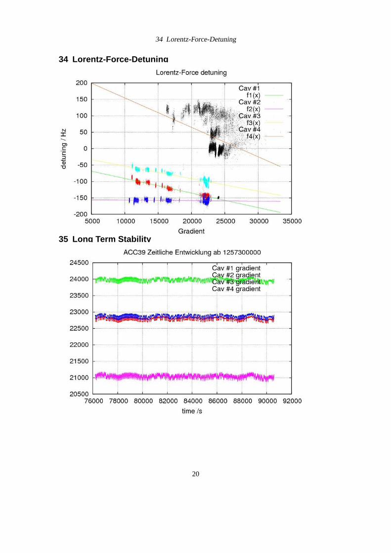
34 Lorentz-Force-Detuning
34 Lorentz-Force-Detuning
35 Long Term Stability
20

36 Status
4. Where are we now?36 Status
1. We have assembled oneVME crate + SIMCON based hardware including a 3.9 GHzconverter boxwith a LLRF system capable of regulation of 4 (up to 8) 3.9 GHz Cavitiesand one RF station.
2. Thenoise performanceof this system was characterized together with ACC39 in thecryomodule teststand.
3. With the newMIMO controller concept, this system fullfills the requirements, as webelieve in.
4. Possible and planned improvements for theFLASH system:
• Hardware
– 16 bit: better field detection. (future)
– passive frontends(downconverters) for feld detection (in progress).
– injected calibration: Automated driftcalibration (in progress).
• Software
37 Status (2)
5. Possible and planned improvements for theFLASH system:
• Software
– NON-IQ sampling (54 MHz) for SIMCON
– Master-Slave-Betriebfor two SIMCON-Boards (future)
– injected calibration realised in firmware (in progress)
– Referenztrackingrealised in firmware (in progress)
– Learning Feed-Forwardsrealised
– Anpassung desDOOCS Servers– Überarbeitung der Bedienoberfläche/Panels– Kopplung der Settings und ACC1-Arbeitspunkt durchAutomation
6. Changes for theXFEL System:
• 4−→ 8 cavities
• common crate standard (ATCA?)
• ...
21

38 To Be Done
38 To Be Done
7. simulation softwareneed to be worked on to understand:
• Impact of Field stability on beam parameters
• The necessary requirements for LLRF control
8. commissioningprocedure need to be worked out after FLASH upgrade. (in Progress)
9. We need to find a good way how to operate ACC1 and ACC39 simultanously.
The End
Further information to all LLRF related topics, progress and status of the projects can be foundonhttp://mskpc14.desy.de/wiki/.
22
Related Documents


