SP 1800 SP 2800 CAT Original operating instructions Stationary concrete pump

Welcome message from author
This document is posted to help you gain knowledge. Please leave a comment to let me know what you think about it! Share it to your friends and learn new things together.
Transcript
Original operating instructions
Stationary concrete pump
SP 1800
SP 2800CAT
Dear Customer,
These operating instructions describe all series and special equipment of your ma-chine available at the time of publication.
Country-specific differences are possible.
Please note that your machine cannot be equipped with all described functions. This also applies to safety-relevant systems and functions.
The operating instructions are an integral part of the machine.
Always keep the operating instructions readily available on to machine so they can be viewed at all times.
Please ensure prompt replacement of the operating instructions if they should be-come lost.
Specify the machine type and the machine number stamped on the type plate of your machine when placing an order.
Pass on these operating instructions when leaving the machine to someone else.
Imprint:
All rights reserved.
Reprint - in whole or in part - only with the prior consent of the publisher.
Editor: Schwing GmbH
Department: TDS 1
Address: Heerstr. 9-27
44653 Herne
GERMANY
Article number of the operating instructions:
98373677
Caterpillar 129, 151, 168 kW
Printed on: 7. January 2019
Version / Language: 3.12 / English
2 Titelseite-SP-1800-2800-EN.fm -
1 Contents
1 Contents
1 Contents . . . . . . . . . . . . . . . . . . . . . . . . . . . . . . . . . . . . . . . . . . . . . . . . . . . . . . . . . . . . . . 1
2 Introduction . . . . . . . . . . . . . . . . . . . . . . . . . . . . . . . . . . . . . . . . . . . . . . . . . . . . . . . . . . 11
2.1 Preface . . . . . . . . . . . . . . . . . . . . . . . . . . . . . . . . . . . . . . . . . . . . . . . . . . . . . . . . . . . . . . . 13
2.1.1 Supplier documentation. . . . . . . . . . . . . . . . . . . . . . . . . . . . . . . . . . . . . . . . . . . . . . . . . . . . 14
2.2 Structure of the operating instructions . . . . . . . . . . . . . . . . . . . . . . . . . . . . . . . . . . . . . 15
2.2.1 Typographic conventions . . . . . . . . . . . . . . . . . . . . . . . . . . . . . . . . . . . . . . . . . . . . . . . . . . 15
2.2.2 Contents of the individual chapters in these operating instructions. . . . . . . . . . . . . . . . . . . 16
2.2.3 Page layout of the operating instructions . . . . . . . . . . . . . . . . . . . . . . . . . . . . . . . . . . . . . . 17
2.2.4 Structure of safety instructions . . . . . . . . . . . . . . . . . . . . . . . . . . . . . . . . . . . . . . . . . . . . . . 18
2.2.5 Warning of personal injury . . . . . . . . . . . . . . . . . . . . . . . . . . . . . . . . . . . . . . . . . . . . . . . . . 18
2.2.6 Warning of material damage . . . . . . . . . . . . . . . . . . . . . . . . . . . . . . . . . . . . . . . . . . . . . . . . 19
2.2.7 Additional information . . . . . . . . . . . . . . . . . . . . . . . . . . . . . . . . . . . . . . . . . . . . . . . . . . . . . 19
2.3 CE labelling . . . . . . . . . . . . . . . . . . . . . . . . . . . . . . . . . . . . . . . . . . . . . . . . . . . . . . . . . . . 21
2.3.1 Declaration of conformity . . . . . . . . . . . . . . . . . . . . . . . . . . . . . . . . . . . . . . . . . . . . . . . . . . 21
2.3.2 EC declaration of conformity for truck-mounted concrete pumps . . . . . . . . . . . . . . . . . . . . 22
2.3.3 EC declaration of conformity for stationary concrete pumps. . . . . . . . . . . . . . . . . . . . . . . . 23
2.3.4 Termination of the declaration of conformity . . . . . . . . . . . . . . . . . . . . . . . . . . . . . . . . . . . . 24
2.4 Theoretical service life of a machine . . . . . . . . . . . . . . . . . . . . . . . . . . . . . . . . . . . . . . . 25
2.4.1 Final decommissioning and disposal of the machine . . . . . . . . . . . . . . . . . . . . . . . . . . . . . 26
2.5 Labelling SCHWING machines . . . . . . . . . . . . . . . . . . . . . . . . . . . . . . . . . . . . . . . . . . . . 27
2.5.1 Stationary concrete pumps . . . . . . . . . . . . . . . . . . . . . . . . . . . . . . . . . . . . . . . . . . . . . . . . . 27
2.5.2 Additional designations . . . . . . . . . . . . . . . . . . . . . . . . . . . . . . . . . . . . . . . . . . . . . . . . . . . 27
2.5.3 Type plates . . . . . . . . . . . . . . . . . . . . . . . . . . . . . . . . . . . . . . . . . . . . . . . . . . . . . . . . . . . . . 27
2.6 Technical data for SP 1800 / 2800 CAT . . . . . . . . . . . . . . . . . . . . . . . . . . . . . . . . . . . . . 29
2.7 Assembly groups and designations for your machine SP 1800 / 2800 . . . . . . . . . . . 37
2.7.1 Machine description . . . . . . . . . . . . . . . . . . . . . . . . . . . . . . . . . . . . . . . . . . . . . . . . . . . . . . 37
2.7.2 Transport option . . . . . . . . . . . . . . . . . . . . . . . . . . . . . . . . . . . . . . . . . . . . . . . . . . . . . . . . . 37
2.7.3 Drive motors . . . . . . . . . . . . . . . . . . . . . . . . . . . . . . . . . . . . . . . . . . . . . . . . . . . . . . . . . . . . 37
2.7.4 Hydraulic system . . . . . . . . . . . . . . . . . . . . . . . . . . . . . . . . . . . . . . . . . . . . . . . . . . . . . . . . 37
2.7.5 Concrete pump . . . . . . . . . . . . . . . . . . . . . . . . . . . . . . . . . . . . . . . . . . . . . . . . . . . . . . . . . . 38
2.7.6 Rock valve . . . . . . . . . . . . . . . . . . . . . . . . . . . . . . . . . . . . . . . . . . . . . . . . . . . . . . . . . . . . . 38
98373677-SP-1800-2800-ENIVZ.fm - 1
1 Contents
2.7.7 On the left in the direction of travel. . . . . . . . . . . . . . . . . . . . . . . . . . . . . . . . . . . . . . . . . . . 40
2.7.8 On the right in the direction of travel. . . . . . . . . . . . . . . . . . . . . . . . . . . . . . . . . . . . . . . . . . 41
2.7.9 Aerial view . . . . . . . . . . . . . . . . . . . . . . . . . . . . . . . . . . . . . . . . . . . . . . . . . . . . . . . . . . . . . 42
2.8 Noise information . . . . . . . . . . . . . . . . . . . . . . . . . . . . . . . . . . . . . . . . . . . . . . . . . . . . . . . 43
2.8.2 The highest sound pressure level (LpA). . . . . . . . . . . . . . . . . . . . . . . . . . . . . . . . . . . . . . . 44
2.9 Pictographs without text . . . . . . . . . . . . . . . . . . . . . . . . . . . . . . . . . . . . . . . . . . . . . . . . . 47
2.9.1 Pictographs. . . . . . . . . . . . . . . . . . . . . . . . . . . . . . . . . . . . . . . . . . . . . . . . . . . . . . . . . . . . . 48
2.10 Control, warning and steering elements SP 1800 / 2800 . . . . . . . . . . . . . . . . . . . . . . . 51
2.10.1 Concrete pump control . . . . . . . . . . . . . . . . . . . . . . . . . . . . . . . . . . . . . . . . . . . . . . . . . . . . 51
2.10.2 Cable remote control . . . . . . . . . . . . . . . . . . . . . . . . . . . . . . . . . . . . . . . . . . . . . . . . . . . . . . 53
2.10.3 CAT control (IOPU control panel) . . . . . . . . . . . . . . . . . . . . . . . . . . . . . . . . . . . . . . . . . . . . 54
2.10.4 TSC function. . . . . . . . . . . . . . . . . . . . . . . . . . . . . . . . . . . . . . . . . . . . . . . . . . . . . . . . . . . . 56
2.10.5 “Regeneration” instructions . . . . . . . . . . . . . . . . . . . . . . . . . . . . . . . . . . . . . . . . . . . . . . . . 57
2.10.6 Hydraulic oil filter . . . . . . . . . . . . . . . . . . . . . . . . . . . . . . . . . . . . . . . . . . . . . . . . . . . . . . . . . 60
2.10.7 Water separator . . . . . . . . . . . . . . . . . . . . . . . . . . . . . . . . . . . . . . . . . . . . . . . . . . . . . . . . . . 60
2.10.8 Output regulation . . . . . . . . . . . . . . . . . . . . . . . . . . . . . . . . . . . . . . . . . . . . . . . . . . . . . . . . . 61
2.10.9 Fuel filter . . . . . . . . . . . . . . . . . . . . . . . . . . . . . . . . . . . . . . . . . . . . . . . . . . . . . . . . . . . . . . . 62
2.10.10 Main switch for starter batteries . . . . . . . . . . . . . . . . . . . . . . . . . . . . . . . . . . . . . . . . . . . . . . 63
2.10.11 Forced motor switch-off . . . . . . . . . . . . . . . . . . . . . . . . . . . . . . . . . . . . . . . . . . . . . . . . . . . 64
3 Operation . . . . . . . . . . . . . . . . . . . . . . . . . . . . . . . . . . . . . . . . . . . . . . . . . . . . . . . . . . . . 65
3.1 Driving operation PLC . . . . . . . . . . . . . . . . . . . . . . . . . . . . . . . . . . . . . . . . . . . . . . . . . . . 67
3.1.1 Environmental protection and accident prevention . . . . . . . . . . . . . . . . . . . . . . . . . . . . . . . 67
3.1.2 Air pressure table . . . . . . . . . . . . . . . . . . . . . . . . . . . . . . . . . . . . . . . . . . . . . . . . . . . . . . . . 67
3.1.3 Transporting people and goods . . . . . . . . . . . . . . . . . . . . . . . . . . . . . . . . . . . . . . . . . . . . . . 68
3.2 Installation site of the stationary concrete pump . . . . . . . . . . . . . . . . . . . . . . . . . . . . . 69
3.2.1 Earthing to prevent static charges . . . . . . . . . . . . . . . . . . . . . . . . . . . . . . . . . . . . . . . . . . . . 70
3.3 Electrical connection (optional) . . . . . . . . . . . . . . . . . . . . . . . . . . . . . . . . . . . . . . . . . . . 73
3.3.1 Instructions for electricians . . . . . . . . . . . . . . . . . . . . . . . . . . . . . . . . . . . . . . . . . . . . . . . . . 73
3.3.2 Checking the rotational direction of the electric motors (control without phase sequence mon-itoring) 74
3.3.3 Checking the rotational direction of the electric motors (control with phase sequence monitor-ing) 75
3.4 EMERGENCY-STOP system for SP 1800 / 2800 . . . . . . . . . . . . . . . . . . . . . . . . . . . . . . . 77
3.4.1 Restarting the machine after an EMERGENCY STOP . . . . . . . . . . . . . . . . . . . . . . . . . . . 79
2 98373677-SP-1800-2800-ENIVZ.fm -
1 Contents
3.5 Readying the machine for operation SP 1800/2800 . . . . . . . . . . . . . . . . . . . . . . . . . . . 81
3.5.1 Diesel engine . . . . . . . . . . . . . . . . . . . . . . . . . . . . . . . . . . . . . . . . . . . . . . . . . . . . . . . . . . . 84
3.5.2 Fuel prefilter . . . . . . . . . . . . . . . . . . . . . . . . . . . . . . . . . . . . . . . . . . . . . . . . . . . . . . . . . . . 86
3.5.3 AdBlue reservoir . . . . . . . . . . . . . . . . . . . . . . . . . . . . . . . . . . . . . . . . . . . . . . . . . . . . . . . . . 86
3.5.4 Theoretical operating time. . . . . . . . . . . . . . . . . . . . . . . . . . . . . . . . . . . . . . . . . . . . . . . . . . 89
3.5.5 Example of an operating time calculation . . . . . . . . . . . . . . . . . . . . . . . . . . . . . . . . . . . . . . 90
3.6 Drive circuit SP 1800 / 2800 . . . . . . . . . . . . . . . . . . . . . . . . . . . . . . . . . . . . . . . . . . . . . . 91
3.6.1 Starting the diesel engine . . . . . . . . . . . . . . . . . . . . . . . . . . . . . . . . . . . . . . . . . . . . . . . . . . 91
3.6.2 Switching off the diesel engine . . . . . . . . . . . . . . . . . . . . . . . . . . . . . . . . . . . . . . . . . . . . . . 93
3.6.3 Forced switch-off of motor . . . . . . . . . . . . . . . . . . . . . . . . . . . . . . . . . . . . . . . . . . . . . . . . . 94
3.7 Setting up the machine . . . . . . . . . . . . . . . . . . . . . . . . . . . . . . . . . . . . . . . . . . . . . . . . . . 97
3.7.1 Downtimes. . . . . . . . . . . . . . . . . . . . . . . . . . . . . . . . . . . . . . . . . . . . . . . . . . . . . . . . . . . . . . 98
3.7.2 Outrigger variants . . . . . . . . . . . . . . . . . . . . . . . . . . . . . . . . . . . . . . . . . . . . . . . . . . . . . . . . 98
3.7.3 Machine with chassis frame (SP 1800) . . . . . . . . . . . . . . . . . . . . . . . . . . . . . . . . . . . . . . . 99
3.7.4 Machine with chassis frame (SP 3800) . . . . . . . . . . . . . . . . . . . . . . . . . . . . . . . . . . . . . . 101
3.7.5 Mechanical outrigger . . . . . . . . . . . . . . . . . . . . . . . . . . . . . . . . . . . . . . . . . . . . . . . . . . . . 103
3.7.6 Semi-hydraulic outrigger (optional) . . . . . . . . . . . . . . . . . . . . . . . . . . . . . . . . . . . . . . . . . . 104
3.7.7 Servicing the crank support . . . . . . . . . . . . . . . . . . . . . . . . . . . . . . . . . . . . . . . . . . . . . . . . 105
3.8 Operating the pumping line . . . . . . . . . . . . . . . . . . . . . . . . . . . . . . . . . . . . . . . . . . . . . 107
3.8.1 Observation during operation . . . . . . . . . . . . . . . . . . . . . . . . . . . . . . . . . . . . . . . . . . . . . . 107
3.8.2 Marking pumping pipes and elbows . . . . . . . . . . . . . . . . . . . . . . . . . . . . . . . . . . . . . . . . . 108
3.8.3 Marking the pumping line on the placing boom . . . . . . . . . . . . . . . . . . . . . . . . . . . . . . . . 110
3.8.4 Pumping line on the placing boom . . . . . . . . . . . . . . . . . . . . . . . . . . . . . . . . . . . . . . . . . . 111
3.8.5 Disclaimer . . . . . . . . . . . . . . . . . . . . . . . . . . . . . . . . . . . . . . . . . . . . . . . . . . . . . . . . . . . . . 112
3.8.6 Reconnectable concrete pumps . . . . . . . . . . . . . . . . . . . . . . . . . . . . . . . . . . . . . . . . . . . . 113
3.8.7 Short outlet (foldable) . . . . . . . . . . . . . . . . . . . . . . . . . . . . . . . . . . . . . . . . . . . . . . . . . . . . 115
3.8.8 Short outlet (foldable and rotatable) . . . . . . . . . . . . . . . . . . . . . . . . . . . . . . . . . . . . . . . . . 116
3.8.9 Large outlet DN 180/180/150 (foldable) . . . . . . . . . . . . . . . . . . . . . . . . . . . . . . . . . . . . . . 118
3.8.10 Servicing the foldable and rotatable outlet . . . . . . . . . . . . . . . . . . . . . . . . . . . . . . . . . . . . 119
3.8.11 Separate pumping line . . . . . . . . . . . . . . . . . . . . . . . . . . . . . . . . . . . . . . . . . . . . . . . . . . . 119
3.8.12 Concrete pumping hoses. . . . . . . . . . . . . . . . . . . . . . . . . . . . . . . . . . . . . . . . . . . . . . . . . . 122
3.8.13 Connecting hoses . . . . . . . . . . . . . . . . . . . . . . . . . . . . . . . . . . . . . . . . . . . . . . . . . . . . . . . 123
3.8.14 Hose pipes . . . . . . . . . . . . . . . . . . . . . . . . . . . . . . . . . . . . . . . . . . . . . . . . . . . . . . . . . . . . 124
3.9 Working operation - General information SP 1800 / SP 2800 . . . . . . . . . . . . . . . . . . 127
3.9.1 Special equipment . . . . . . . . . . . . . . . . . . . . . . . . . . . . . . . . . . . . . . . . . . . . . . . . . . . . . . 127
3.9.2 CP remote control . . . . . . . . . . . . . . . . . . . . . . . . . . . . . . . . . . . . . . . . . . . . . . . . . . . . . . . 128
98373677-SP-1800-2800-ENIVZ.fm - 3
1 Contents
3.9.3 CP local control . . . . . . . . . . . . . . . . . . . . . . . . . . . . . . . . . . . . . . . . . . . . . . . . . . . . . . . . . 129
3.9.4 Close maintenance flaps . . . . . . . . . . . . . . . . . . . . . . . . . . . . . . . . . . . . . . . . . . . . . . . . . 130
3.10 Working operation - Concrete pump SP 1800 / 2800 . . . . . . . . . . . . . . . . . . . . . . . . . . 131
3.10.1 General . . . . . . . . . . . . . . . . . . . . . . . . . . . . . . . . . . . . . . . . . . . . . . . . . . . . . . . . . . . . . . . 131
3.10.2 Operational readiness . . . . . . . . . . . . . . . . . . . . . . . . . . . . . . . . . . . . . . . . . . . . . . . . . . . . 132
3.10.3 Agitator . . . . . . . . . . . . . . . . . . . . . . . . . . . . . . . . . . . . . . . . . . . . . . . . . . . . . . . . . . . . . . . 132
3.10.4 Vibrator (special equipment) . . . . . . . . . . . . . . . . . . . . . . . . . . . . . . . . . . . . . . . . . . . . . . . 133
3.10.5 Concrete pump . . . . . . . . . . . . . . . . . . . . . . . . . . . . . . . . . . . . . . . . . . . . . . . . . . . . . . . . . 134
3.10.6 Switching off the concrete pump, agitator and special equipment . . . . . . . . . . . . . . . . . . 135
3.10.7 Reconnecting the concrete pump . . . . . . . . . . . . . . . . . . . . . . . . . . . . . . . . . . . . . . . . . . . 135
3.11 Working operation - Auxiliary power units . . . . . . . . . . . . . . . . . . . . . . . . . . . . . . . . . 139
3.12 Working operation - Water system SP 1800 / 2800 . . . . . . . . . . . . . . . . . . . . . . . . . . . 141
3.12.1 Preparation . . . . . . . . . . . . . . . . . . . . . . . . . . . . . . . . . . . . . . . . . . . . . . . . . . . . . . . . . . . . 141
3.12.2 Operation . . . . . . . . . . . . . . . . . . . . . . . . . . . . . . . . . . . . . . . . . . . . . . . . . . . . . . . . . . . . . 142
3.12.3 End of operation . . . . . . . . . . . . . . . . . . . . . . . . . . . . . . . . . . . . . . . . . . . . . . . . . . . . . . . . 143
3.12.4 Winter operation . . . . . . . . . . . . . . . . . . . . . . . . . . . . . . . . . . . . . . . . . . . . . . . . . . . . . . . . 143
3.13 Working operation - Air system SP 1800 / 2800 . . . . . . . . . . . . . . . . . . . . . . . . . . . . . . 145
3.13.1 Preparation . . . . . . . . . . . . . . . . . . . . . . . . . . . . . . . . . . . . . . . . . . . . . . . . . . . . . . . . . . . . 145
3.13.2 Operation . . . . . . . . . . . . . . . . . . . . . . . . . . . . . . . . . . . . . . . . . . . . . . . . . . . . . . . . . . . . . . 146
3.13.3 End of operation . . . . . . . . . . . . . . . . . . . . . . . . . . . . . . . . . . . . . . . . . . . . . . . . . . . . . . . . 147
3.13.4 Winter operation . . . . . . . . . . . . . . . . . . . . . . . . . . . . . . . . . . . . . . . . . . . . . . . . . . . . . . . . 147
3.14 Working operation - Hydraulic shut-off assembly (special equipment) . . . . . . . . . . 149
3.14.1 Preparation . . . . . . . . . . . . . . . . . . . . . . . . . . . . . . . . . . . . . . . . . . . . . . . . . . . . . . . . . . . . 149
3.14.2 Operation . . . . . . . . . . . . . . . . . . . . . . . . . . . . . . . . . . . . . . . . . . . . . . . . . . . . . . . . . . . . . . 149
3.15 Clearing blockages . . . . . . . . . . . . . . . . . . . . . . . . . . . . . . . . . . . . . . . . . . . . . . . . . . . . . 151
3.15.1 Blockage in the pumping line . . . . . . . . . . . . . . . . . . . . . . . . . . . . . . . . . . . . . . . . . . . . . . . 152
3.15.2 Mechanical blockage . . . . . . . . . . . . . . . . . . . . . . . . . . . . . . . . . . . . . . . . . . . . . . . . . . . . . 153
3.16 Control of operations SP 1800/2800 . . . . . . . . . . . . . . . . . . . . . . . . . . . . . . . . . . . . . . . 155
3.16.1 Control of operations for concrete pump . . . . . . . . . . . . . . . . . . . . . . . . . . . . . . . . . . . . . . 155
3.16.2 Switching damping . . . . . . . . . . . . . . . . . . . . . . . . . . . . . . . . . . . . . . . . . . . . . . . . . . . . . . 159
3.16.3 Control of operations for diesel engine . . . . . . . . . . . . . . . . . . . . . . . . . . . . . . . . . . . . . . . 160
3.17 Troubleshooting - Emergency operation SP 1800 / 2800 . . . . . . . . . . . . . . . . . . . . . . 163
3.17.1 Control failure . . . . . . . . . . . . . . . . . . . . . . . . . . . . . . . . . . . . . . . . . . . . . . . . . . . . . . . . . . 163
3.17.2 Electrical fuse protection for the machine control system . . . . . . . . . . . . . . . . . . . . . . . . . 163
4 98373677-SP-1800-2800-ENIVZ.fm -
1 Contents
3.17.3 Bypass . . . . . . . . . . . . . . . . . . . . . . . . . . . . . . . . . . . . . . . . . . . . . . . . . . . . . . . . . . . . . . . 165
3.17.4 Directional valve emergency actuation . . . . . . . . . . . . . . . . . . . . . . . . . . . . . . . . . . . . . . . 166
3.17.5 EMERGENCY-STOP valve. . . . . . . . . . . . . . . . . . . . . . . . . . . . . . . . . . . . . . . . . . . . . . . . 167
3.18 Cleaning . . . . . . . . . . . . . . . . . . . . . . . . . . . . . . . . . . . . . . . . . . . . . . . . . . . . . . . . . . . . . 169
3.18.1 Cleaning devices . . . . . . . . . . . . . . . . . . . . . . . . . . . . . . . . . . . . . . . . . . . . . . . . . . . . . . . 169
3.18.2 Cleaning the pumping line . . . . . . . . . . . . . . . . . . . . . . . . . . . . . . . . . . . . . . . . . . . . . . . . 170
3.18.3 Reverse pumping concrete . . . . . . . . . . . . . . . . . . . . . . . . . . . . . . . . . . . . . . . . . . . . . . . . 171
3.18.4 Clearing the pumping line with water. . . . . . . . . . . . . . . . . . . . . . . . . . . . . . . . . . . . . . . . . 176
3.18.5 Rinsing the pumping line . . . . . . . . . . . . . . . . . . . . . . . . . . . . . . . . . . . . . . . . . . . . . . . . . 176
3.18.6 Blowing out the pumping line with compressed air . . . . . . . . . . . . . . . . . . . . . . . . . . . . . . 178
3.18.7 Cleaning the concrete pump . . . . . . . . . . . . . . . . . . . . . . . . . . . . . . . . . . . . . . . . . . . . . . . 180
3.18.8 Securing the machine . . . . . . . . . . . . . . . . . . . . . . . . . . . . . . . . . . . . . . . . . . . . . . . . . . . . 180
3.18.9 Interior cleaning . . . . . . . . . . . . . . . . . . . . . . . . . . . . . . . . . . . . . . . . . . . . . . . . . . . . . . . . 180
3.18.10 Exterior cleaning . . . . . . . . . . . . . . . . . . . . . . . . . . . . . . . . . . . . . . . . . . . . . . . . . . . . . . . . 184
3.18.11 Using high-pressure cleaners (HP cleaners) . . . . . . . . . . . . . . . . . . . . . . . . . . . . . . . . . . 185
3.18.12 Using cleaning agents . . . . . . . . . . . . . . . . . . . . . . . . . . . . . . . . . . . . . . . . . . . . . . . . . . . . 186
3.18.13 After cleaning . . . . . . . . . . . . . . . . . . . . . . . . . . . . . . . . . . . . . . . . . . . . . . . . . . . . . . . . . . 186
3.18.14 Water box flushing (special equipment) . . . . . . . . . . . . . . . . . . . . . . . . . . . . . . . . . . . . . . 186
3.19 Hazard prevention on the concrete filling hopper . . . . . . . . . . . . . . . . . . . . . . . . . . . 189
3.19.1 Hopper grate . . . . . . . . . . . . . . . . . . . . . . . . . . . . . . . . . . . . . . . . . . . . . . . . . . . . . . . . . . 189
3.19.2 Cleaning flap and pipeline outlet . . . . . . . . . . . . . . . . . . . . . . . . . . . . . . . . . . . . . . . . . . . 190
3.20 Establishing transport readiness . . . . . . . . . . . . . . . . . . . . . . . . . . . . . . . . . . . . . . . . . 191
3.20.1 Mechanical outrigger SP 1800 . . . . . . . . . . . . . . . . . . . . . . . . . . . . . . . . . . . . . . . . . . . . . 191
3.20.2 Mechanical outrigger SP 3800 . . . . . . . . . . . . . . . . . . . . . . . . . . . . . . . . . . . . . . . . . . . . . 193
3.20.3 Semi-hydraulic outrigger SP 1800 . . . . . . . . . . . . . . . . . . . . . . . . . . . . . . . . . . . . . . . . . . 195
3.20.4 Semi-hydraulic outrigger SP 3800 . . . . . . . . . . . . . . . . . . . . . . . . . . . . . . . . . . . . . . . . . . 196
3.20.5 Coupling SP 1800 . . . . . . . . . . . . . . . . . . . . . . . . . . . . . . . . . . . . . . . . . . . . . . . . . . . . . . 197
3.20.6 Coupling SP 3800 . . . . . . . . . . . . . . . . . . . . . . . . . . . . . . . . . . . . . . . . . . . . . . . . . . . . . . 197
3.20.7 Crane loading . . . . . . . . . . . . . . . . . . . . . . . . . . . . . . . . . . . . . . . . . . . . . . . . . . . . . . . . . . 198
3.21 Difficult operating conditions . . . . . . . . . . . . . . . . . . . . . . . . . . . . . . . . . . . . . . . . . . . . 199
3.21.1 Low ambient temperatures (up to -15 °C) . . . . . . . . . . . . . . . . . . . . . . . . . . . . . . . . . . . . . 200
3.21.2 High ambient temperatures . . . . . . . . . . . . . . . . . . . . . . . . . . . . . . . . . . . . . . . . . . . . . . . 207
3.22 Decommissioning . . . . . . . . . . . . . . . . . . . . . . . . . . . . . . . . . . . . . . . . . . . . . . . . . . . . . 213
3.22.1 Tasks prior to decommissioning . . . . . . . . . . . . . . . . . . . . . . . . . . . . . . . . . . . . . . . . . . . . 213
3.22.2 Recommissioning . . . . . . . . . . . . . . . . . . . . . . . . . . . . . . . . . . . . . . . . . . . . . . . . . . . . . . . 214
98373677-SP-1800-2800-ENIVZ.fm - 5
1 Contents
3.23 Technical preconditions for concreting . . . . . . . . . . . . . . . . . . . . . . . . . . . . . . . . . . . . 215
3.23.1 Properties of pumped concrete . . . . . . . . . . . . . . . . . . . . . . . . . . . . . . . . . . . . . . . . . . . . . 215
3.23.2 Errors that inhibit pumping . . . . . . . . . . . . . . . . . . . . . . . . . . . . . . . . . . . . . . . . . . . . . . . . . 215
4 Maintenance . . . . . . . . . . . . . . . . . . . . . . . . . . . . . . . . . . . . . . . . . . . . . . . . . . . . . . . . . 217
4.1 General maintenance instructions . . . . . . . . . . . . . . . . . . . . . . . . . . . . . . . . . . . . . . . . 219
4.1.1 Maintenance work on special equipment . . . . . . . . . . . . . . . . . . . . . . . . . . . . . . . . . . . . . 219
4.1.2 Cleanliness . . . . . . . . . . . . . . . . . . . . . . . . . . . . . . . . . . . . . . . . . . . . . . . . . . . . . . . . . . . . 219
4.1.3 Corrosion protection . . . . . . . . . . . . . . . . . . . . . . . . . . . . . . . . . . . . . . . . . . . . . . . . . . . . . 220
4.1.4 Checking the oil level . . . . . . . . . . . . . . . . . . . . . . . . . . . . . . . . . . . . . . . . . . . . . . . . . . . . . 220
4.1.5 Oil change . . . . . . . . . . . . . . . . . . . . . . . . . . . . . . . . . . . . . . . . . . . . . . . . . . . . . . . . . . . . . 220
4.1.6 Draining condensation water . . . . . . . . . . . . . . . . . . . . . . . . . . . . . . . . . . . . . . . . . . . . . . . 221
4.1.7 Seals and fuse elements . . . . . . . . . . . . . . . . . . . . . . . . . . . . . . . . . . . . . . . . . . . . . . . . . . 221
4.1.8 Lubrication . . . . . . . . . . . . . . . . . . . . . . . . . . . . . . . . . . . . . . . . . . . . . . . . . . . . . . . . . . . . 222
4.1.9 Leaks . . . . . . . . . . . . . . . . . . . . . . . . . . . . . . . . . . . . . . . . . . . . . . . . . . . . . . . . . . . . . . . . . 222
4.1.10 Repairs, exchange . . . . . . . . . . . . . . . . . . . . . . . . . . . . . . . . . . . . . . . . . . . . . . . . . . . . . . . 222
4.1.11 Welding . . . . . . . . . . . . . . . . . . . . . . . . . . . . . . . . . . . . . . . . . . . . . . . . . . . . . . . . . . . . . . . 223
4.1.12 Mechanical processes . . . . . . . . . . . . . . . . . . . . . . . . . . . . . . . . . . . . . . . . . . . . . . . . . . . . 223
4.1.13 Painting and working with aggressive substances . . . . . . . . . . . . . . . . . . . . . . . . . . . . . . 223
4.1.14 High-pressure cleaning . . . . . . . . . . . . . . . . . . . . . . . . . . . . . . . . . . . . . . . . . . . . . . . . . . . 223
4.1.15 Electrically powered machines . . . . . . . . . . . . . . . . . . . . . . . . . . . . . . . . . . . . . . . . . . . . . 224
4.2 Consumable volumes (in litres) . . . . . . . . . . . . . . . . . . . . . . . . . . . . . . . . . . . . . . . . . . 225
4.3 Recommended lubricants and fuels . . . . . . . . . . . . . . . . . . . . . . . . . . . . . . . . . . . . . . . 227
4.3.1 Behaviour in case of injuries. . . . . . . . . . . . . . . . . . . . . . . . . . . . . . . . . . . . . . . . . . . . . . . 228
4.3.2 Explanation of the abbreviations used . . . . . . . . . . . . . . . . . . . . . . . . . . . . . . . . . . . . . . . . 228
4.3.3 Recommended hydraulic oil . . . . . . . . . . . . . . . . . . . . . . . . . . . . . . . . . . . . . . . . . . . . . . . 230
4.3.4 Recommended gear oil (see gear type plate) . . . . . . . . . . . . . . . . . . . . . . . . . . . . . . . . . 231
4.3.5 Recommended compressor oil . . . . . . . . . . . . . . . . . . . . . . . . . . . . . . . . . . . . . . . . . . . . . 233
4.3.6 Recommended grease . . . . . . . . . . . . . . . . . . . . . . . . . . . . . . . . . . . . . . . . . . . . . . . . . . . 234
4.3.7 Excerpt from the safety data sheet for hydraulic oil . . . . . . . . . . . . . . . . . . . . . . . . . . . . . 236
4.4 Spare parts and accessories . . . . . . . . . . . . . . . . . . . . . . . . . . . . . . . . . . . . . . . . . . . . . 239
4.4.1 Wear parts - Signs of wear . . . . . . . . . . . . . . . . . . . . . . . . . . . . . . . . . . . . . . . . . . . . . . . . 240
4.5 Explanation of the maintenance schedule - Stationary concrete pump . . . . . . . . . . 243
4.6 Maintenance plan for stationary concrete pump SP 1800/2800 . . . . . . . . . . . . . . . . . 245
4.6.1 General information . . . . . . . . . . . . . . . . . . . . . . . . . . . . . . . . . . . . . . . . . . . . . . . . . . . . . . 245
6 98373677-SP-1800-2800-ENIVZ.fm -
1 Contents
4.6.2 Concrete pump (pump kit) . . . . . . . . . . . . . . . . . . . . . . . . . . . . . . . . . . . . . . . . . . . . . . . . . 246
4.6.3 Special equipment . . . . . . . . . . . . . . . . . . . . . . . . . . . . . . . . . . . . . . . . . . . . . . . . . . . . . . . 247
4.6.4 Test intervals according to concrete delivery rate . . . . . . . . . . . . . . . . . . . . . . . . . . . . . . . 248
4.7 Maintenance report . . . . . . . . . . . . . . . . . . . . . . . . . . . . . . . . . . . . . . . . . . . . . . . . . . . . 249
4.8 Hydraulic fluid and filters for stationary concrete pump . . . . . . . . . . . . . . . . . . . . . . 251
4.8.1 Checking the fill level of the reservoir . . . . . . . . . . . . . . . . . . . . . . . . . . . . . . . . . . . . . . . . 251
4.8.2 Filling the empty oil box . . . . . . . . . . . . . . . . . . . . . . . . . . . . . . . . . . . . . . . . . . . . . . . . . . 252
4.8.3 Purity of the hydraulic oil . . . . . . . . . . . . . . . . . . . . . . . . . . . . . . . . . . . . . . . . . . . . . . . . . 252
4.8.4 What does the purity classification mean? . . . . . . . . . . . . . . . . . . . . . . . . . . . . . . . . . . . . 253
4.8.5 What advantages are there in observing the purity classification? . . . . . . . . . . . . . . . . . . 254
4.8.6 Extended changing intervals for hydraulic oil . . . . . . . . . . . . . . . . . . . . . . . . . . . . . . . . . . 254
4.8.7 Description of the oil sampling procedure . . . . . . . . . . . . . . . . . . . . . . . . . . . . . . . . . . . . 254
4.8.8 Draining condensation water . . . . . . . . . . . . . . . . . . . . . . . . . . . . . . . . . . . . . . . . . . . . . . 255
4.8.9 Changing the hydraulic fluid . . . . . . . . . . . . . . . . . . . . . . . . . . . . . . . . . . . . . . . . . . . . . . . 256
4.8.10 Cleaning the reservoir . . . . . . . . . . . . . . . . . . . . . . . . . . . . . . . . . . . . . . . . . . . . . . . . . . . 256
4.8.11 Changing the insert on the main filter (return flow filter) . . . . . . . . . . . . . . . . . . . . . . . . . . 257
4.9 Pressure checks - stationary concrete pumps . . . . . . . . . . . . . . . . . . . . . . . . . . . . . . 261
4.9.1 Concrete pump system . . . . . . . . . . . . . . . . . . . . . . . . . . . . . . . . . . . . . . . . . . . . . . . . . . . 261
4.9.2 Performing a pressure check . . . . . . . . . . . . . . . . . . . . . . . . . . . . . . . . . . . . . . . . . . . . . . 262
4.10 Radiator . . . . . . . . . . . . . . . . . . . . . . . . . . . . . . . . . . . . . . . . . . . . . . . . . . . . . . . . . . . . . 265
4.10.1 Hydraulic oil cooler . . . . . . . . . . . . . . . . . . . . . . . . . . . . . . . . . . . . . . . . . . . . . . . . . . . . . . 265
4.10.2 Motor cooler . . . . . . . . . . . . . . . . . . . . . . . . . . . . . . . . . . . . . . . . . . . . . . . . . . . . . . . . . . . 266
4.11 Air-filter system . . . . . . . . . . . . . . . . . . . . . . . . . . . . . . . . . . . . . . . . . . . . . . . . . . . . . . . 267
4.11.1 Dust discharge valve . . . . . . . . . . . . . . . . . . . . . . . . . . . . . . . . . . . . . . . . . . . . . . . . . . . . 267
4.11.2 Removing the filter element . . . . . . . . . . . . . . . . . . . . . . . . . . . . . . . . . . . . . . . . . . . . . . . 267
4.11.3 Cleaning the filter element . . . . . . . . . . . . . . . . . . . . . . . . . . . . . . . . . . . . . . . . . . . . . . . . 268
4.11.4 Installing the filter element. . . . . . . . . . . . . . . . . . . . . . . . . . . . . . . . . . . . . . . . . . . . . . . . . 270
4.11.5 Storage . . . . . . . . . . . . . . . . . . . . . . . . . . . . . . . . . . . . . . . . . . . . . . . . . . . . . . . . . . . . . . . 270
4.11.6 Disposal . . . . . . . . . . . . . . . . . . . . . . . . . . . . . . . . . . . . . . . . . . . . . . . . . . . . . . . . . . . . . . 270
4.11.7 Function testing of maintenance indicator . . . . . . . . . . . . . . . . . . . . . . . . . . . . . . . . . . . . 270
4.12 Rock valve . . . . . . . . . . . . . . . . . . . . . . . . . . . . . . . . . . . . . . . . . . . . . . . . . . . . . . . . . . . 271
4.12.1 Lubricating the bearing points . . . . . . . . . . . . . . . . . . . . . . . . . . . . . . . . . . . . . . . . . . . . . 271
4.12.2 Checking the screw-type connections. . . . . . . . . . . . . . . . . . . . . . . . . . . . . . . . . . . . . . . . 274
4.12.3 Checking the axial play of the slewing shaft . . . . . . . . . . . . . . . . . . . . . . . . . . . . . . . . . . . 274
4.12.4 Configuring the axial play of the slewing shaft . . . . . . . . . . . . . . . . . . . . . . . . . . . . . . . . . 275
98373677-SP-1800-2800-ENIVZ.fm - 7
1 Contents
4.12.5 Checking the cutting ring . . . . . . . . . . . . . . . . . . . . . . . . . . . . . . . . . . . . . . . . . . . . . . . . . . 275
4.12.6 Rotating the cutting ring . . . . . . . . . . . . . . . . . . . . . . . . . . . . . . . . . . . . . . . . . . . . . . . . . . . 277
4.12.7 Checking the seal of the slewing shaft . . . . . . . . . . . . . . . . . . . . . . . . . . . . . . . . . . . . . . . 281
4.12.8 Prolonged downtime . . . . . . . . . . . . . . . . . . . . . . . . . . . . . . . . . . . . . . . . . . . . . . . . . . . . . 281
4.12.9 Checking the wear of the rock . . . . . . . . . . . . . . . . . . . . . . . . . . . . . . . . . . . . . . . . . . . . . 282
4.12.10 Preventive maintenance . . . . . . . . . . . . . . . . . . . . . . . . . . . . . . . . . . . . . . . . . . . . . . . . . . 282
4.13 Delivery and differential cylinders, pumping piston change . . . . . . . . . . . . . . . . . . . 285
4.13.1 Pumping piston change . . . . . . . . . . . . . . . . . . . . . . . . . . . . . . . . . . . . . . . . . . . . . . . . . . . 285
4.13.2 Preparing to change the pumping pistons . . . . . . . . . . . . . . . . . . . . . . . . . . . . . . . . . . . . . 286
4.13.3 Checking the fastener . . . . . . . . . . . . . . . . . . . . . . . . . . . . . . . . . . . . . . . . . . . . . . . . . . . . 289
4.13.4 Changing the pumping piston . . . . . . . . . . . . . . . . . . . . . . . . . . . . . . . . . . . . . . . . . . . . . . 290
4.14 High-pressure version (HP) (pumping and differential cylinders) (optional) . . . . . . 295
4.14.1 Pumping pistons . . . . . . . . . . . . . . . . . . . . . . . . . . . . . . . . . . . . . . . . . . . . . . . . . . . . . . . . 296
4.14.2 The “Pumping piston change” operating mode . . . . . . . . . . . . . . . . . . . . . . . . . . . . . . . . . 296
4.14.3 Removing the HP pumping pistons . . . . . . . . . . . . . . . . . . . . . . . . . . . . . . . . . . . . . . . . . . 296
4.14.4 Installing the HP pumping pistons . . . . . . . . . . . . . . . . . . . . . . . . . . . . . . . . . . . . . . . . . . . 298
4.15 Multi-part pumping pistons (optional) . . . . . . . . . . . . . . . . . . . . . . . . . . . . . . . . . . . . . 301
4.15.1 Replacing the main wear parts . . . . . . . . . . . . . . . . . . . . . . . . . . . . . . . . . . . . . . . . . . . . . 301
4.16 Servicing the pumping line . . . . . . . . . . . . . . . . . . . . . . . . . . . . . . . . . . . . . . . . . . . . . . 305
4.16.1 Diagrams . . . . . . . . . . . . . . . . . . . . . . . . . . . . . . . . . . . . . . . . . . . . . . . . . . . . . . . . . . . . . 307
4.16.2 Main wear zones . . . . . . . . . . . . . . . . . . . . . . . . . . . . . . . . . . . . . . . . . . . . . . . . . . . . . . . 309
4.16.3 Impact bend . . . . . . . . . . . . . . . . . . . . . . . . . . . . . . . . . . . . . . . . . . . . . . . . . . . . . . . . . . . . 310
4.16.4 Measuring the wall thickness . . . . . . . . . . . . . . . . . . . . . . . . . . . . . . . . . . . . . . . . . . . . . . . 312
4.16.5 Tube type - tubes . . . . . . . . . . . . . . . . . . . . . . . . . . . . . . . . . . . . . . . . . . . . . . . . . . . . . . . 314
4.16.6 Measurement sheet - tubes . . . . . . . . . . . . . . . . . . . . . . . . . . . . . . . . . . . . . . . . . . . . . . . 315
4.16.7 Tube type - elbows . . . . . . . . . . . . . . . . . . . . . . . . . . . . . . . . . . . . . . . . . . . . . . . . . . . . . . 316
4.16.8 Measurement sheet - elbows . . . . . . . . . . . . . . . . . . . . . . . . . . . . . . . . . . . . . . . . . . . . . . 317
4.16.9 Tube type - tapered tubes . . . . . . . . . . . . . . . . . . . . . . . . . . . . . . . . . . . . . . . . . . . . . . . . 318
4.16.10 Extending the service life . . . . . . . . . . . . . . . . . . . . . . . . . . . . . . . . . . . . . . . . . . . . . . . . . . 319
4.16.11 Replacing pumping pipes end elbows . . . . . . . . . . . . . . . . . . . . . . . . . . . . . . . . . . . . . . . 320
4.16.12 Testing the pumping hoses . . . . . . . . . . . . . . . . . . . . . . . . . . . . . . . . . . . . . . . . . . . . . . . . 321
4.16.13 Visual inspection (exterior) . . . . . . . . . . . . . . . . . . . . . . . . . . . . . . . . . . . . . . . . . . . . . . . . 322
4.16.14 Visual inspection (internal) . . . . . . . . . . . . . . . . . . . . . . . . . . . . . . . . . . . . . . . . . . . . . . . . 322
4.16.15 Visual inspection of fixings . . . . . . . . . . . . . . . . . . . . . . . . . . . . . . . . . . . . . . . . . . . . . . . . 322
4.17 Rotary compressor . . . . . . . . . . . . . . . . . . . . . . . . . . . . . . . . . . . . . . . . . . . . . . . . . . . . . 325
4.17.1 Maintenance packages . . . . . . . . . . . . . . . . . . . . . . . . . . . . . . . . . . . . . . . . . . . . . . . . . . . 325
8 98373677-SP-1800-2800-ENIVZ.fm -
1 Contents
4.17.2 Checking the oil level. . . . . . . . . . . . . . . . . . . . . . . . . . . . . . . . . . . . . . . . . . . . . . . . . . . . . 326
4.17.3 Topping up the oil . . . . . . . . . . . . . . . . . . . . . . . . . . . . . . . . . . . . . . . . . . . . . . . . . . . . . . . 327
4.17.4 Changing the oil . . . . . . . . . . . . . . . . . . . . . . . . . . . . . . . . . . . . . . . . . . . . . . . . . . . . . . . . 327
4.17.5 Cleaning / Replacing the air filter . . . . . . . . . . . . . . . . . . . . . . . . . . . . . . . . . . . . . . . . . . . 328
4.17.6 Cleaning the oil cooler . . . . . . . . . . . . . . . . . . . . . . . . . . . . . . . . . . . . . . . . . . . . . . . . . . . 328
4.17.7 Replacing compressed air hoses . . . . . . . . . . . . . . . . . . . . . . . . . . . . . . . . . . . . . . . . . . . 329
4.17.8 Replacing the oil filter . . . . . . . . . . . . . . . . . . . . . . . . . . . . . . . . . . . . . . . . . . . . . . . . . . . . 330
4.17.9 Replacing oil return valves . . . . . . . . . . . . . . . . . . . . . . . . . . . . . . . . . . . . . . . . . . . . . . . . 330
4.17.10 Replacing the oil separator cartridge . . . . . . . . . . . . . . . . . . . . . . . . . . . . . . . . . . . . . . . . 331
4.18 Electrical / Electronic system, software . . . . . . . . . . . . . . . . . . . . . . . . . . . . . . . . . . . . 333
4.18.1 Electrical system: Description . . . . . . . . . . . . . . . . . . . . . . . . . . . . . . . . . . . . . . . . . . . . . . 333
4.18.2 Electrical safeguarding of SCHWING components . . . . . . . . . . . . . . . . . . . . . . . . . . . . . 334
4.18.3 Changing the fuses in SCHWING components . . . . . . . . . . . . . . . . . . . . . . . . . . . . . . . . 335
4.18.4 Working on electrical / electronic components . . . . . . . . . . . . . . . . . . . . . . . . . . . . . . . . . 338
4.18.5 Software . . . . . . . . . . . . . . . . . . . . . . . . . . . . . . . . . . . . . . . . . . . . . . . . . . . . . . . . . . . . . . 339
4.18.6 Electrically powered machines . . . . . . . . . . . . . . . . . . . . . . . . . . . . . . . . . . . . . . . . . . . . . 339
4.18.7 Electric welding procedure . . . . . . . . . . . . . . . . . . . . . . . . . . . . . . . . . . . . . . . . . . . . . . . . 339
4.18.8 Jump starting . . . . . . . . . . . . . . . . . . . . . . . . . . . . . . . . . . . . . . . . . . . . . . . . . . . . . . . . . . 339
4.18.9 Jump starting stationary pumps with batteries connected in series . . . . . . . . . . . . . . . . . 339
4.18.10 Mechanical processes . . . . . . . . . . . . . . . . . . . . . . . . . . . . . . . . . . . . . . . . . . . . . . . . . . . 340
4.18.11 Painting and working with aggressive substances . . . . . . . . . . . . . . . . . . . . . . . . . . . . . . 340
4.18.12 Steam jet cleaning . . . . . . . . . . . . . . . . . . . . . . . . . . . . . . . . . . . . . . . . . . . . . . . . . . . . . . 340
4.18.13 Starter batteries (lead-acid batteries) . . . . . . . . . . . . . . . . . . . . . . . . . . . . . . . . . . . . . . . . 341
4.18.14 Checking the acid level . . . . . . . . . . . . . . . . . . . . . . . . . . . . . . . . . . . . . . . . . . . . . . . . . . . 341
4.18.15 Checking the open-circuit voltage . . . . . . . . . . . . . . . . . . . . . . . . . . . . . . . . . . . . . . . . . . 341
4.18.16 Checking the acid density . . . . . . . . . . . . . . . . . . . . . . . . . . . . . . . . . . . . . . . . . . . . . . . . . 342
4.18.17 Charging the battery . . . . . . . . . . . . . . . . . . . . . . . . . . . . . . . . . . . . . . . . . . . . . . . . . . . . . 342
4.18.18 Maintaining the batteries during machine downtimes . . . . . . . . . . . . . . . . . . . . . . . . . . . . 343
4.18.19 Storage and installation . . . . . . . . . . . . . . . . . . . . . . . . . . . . . . . . . . . . . . . . . . . . . . . . . . 344
4.18.20 Disposal . . . . . . . . . . . . . . . . . . . . . . . . . . . . . . . . . . . . . . . . . . . . . . . . . . . . . . . . . . . . . . 344
4.19 Safety inspections . . . . . . . . . . . . . . . . . . . . . . . . . . . . . . . . . . . . . . . . . . . . . . . . . . . . . 345
4.19.1 Machine operator . . . . . . . . . . . . . . . . . . . . . . . . . . . . . . . . . . . . . . . . . . . . . . . . . . . . . . . 345
4.19.2 Competent person (specialist) . . . . . . . . . . . . . . . . . . . . . . . . . . . . . . . . . . . . . . . . . . . . . 345
4.19.3 Expert . . . . . . . . . . . . . . . . . . . . . . . . . . . . . . . . . . . . . . . . . . . . . . . . . . . . . . . . . . . . . . . . 345
4.19.4 Additional inspections . . . . . . . . . . . . . . . . . . . . . . . . . . . . . . . . . . . . . . . . . . . . . . . . . . . . 345
4.19.5 Technical safety inspection . . . . . . . . . . . . . . . . . . . . . . . . . . . . . . . . . . . . . . . . . . . . . . . . 346
4.19.6 Safety components . . . . . . . . . . . . . . . . . . . . . . . . . . . . . . . . . . . . . . . . . . . . . . . . . . . . . . 346
98373677-SP-1800-2800-ENIVZ.fm - 9
1 Contents
4.19.7 Notification of damage for safety components . . . . . . . . . . . . . . . . . . . . . . . . . . . . . . . . . 347
4.20 Repair welding . . . . . . . . . . . . . . . . . . . . . . . . . . . . . . . . . . . . . . . . . . . . . . . . . . . . . . . . 351
5 Remote control . . . . . . . . . . . . . . . . . . . . . . . . . . . . . . . . . . . . . . . . . . . . . . . . . . . . . . 353
5.1 Remote control . . . . . . . . . . . . . . . . . . . . . . . . . . . . . . . . . . . . . . . . . . . . . . . . . . . . . . . . 355
6 Special equipment . . . . . . . . . . . . . . . . . . . . . . . . . . . . . . . . . . . . . . . . . . . . . . . . . . . . 357
6.1 Hydraulic shut-off assembly (98383777) . . . . . . . . . . . . . . . . . . . . . . . . . . . . . . . . . . . 359
6.1.1 Area of application . . . . . . . . . . . . . . . . . . . . . . . . . . . . . . . . . . . . . . . . . . . . . . . . . . . . . . . 359
6.1.2 Safety . . . . . . . . . . . . . . . . . . . . . . . . . . . . . . . . . . . . . . . . . . . . . . . . . . . . . . . . . . . . . . . . 360
6.1.3 Structure of the system. . . . . . . . . . . . . . . . . . . . . . . . . . . . . . . . . . . . . . . . . . . . . . . . . . . 362
6.1.4 Installation . . . . . . . . . . . . . . . . . . . . . . . . . . . . . . . . . . . . . . . . . . . . . . . . . . . . . . . . . . . . 363
6.1.5 Drive . . . . . . . . . . . . . . . . . . . . . . . . . . . . . . . . . . . . . . . . . . . . . . . . . . . . . . . . . . . . . . . . . 363
6.1.6 Maintenance . . . . . . . . . . . . . . . . . . . . . . . . . . . . . . . . . . . . . . . . . . . . . . . . . . . . . . . . . . . 363
6.1.7 Technical data . . . . . . . . . . . . . . . . . . . . . . . . . . . . . . . . . . . . . . . . . . . . . . . . . . . . . . . . . . 363
6.2 Central lubricating system . . . . . . . . . . . . . . . . . . . . . . . . . . . . . . . . . . . . . . . . . . . . . . . 365
6.2.1 Safety . . . . . . . . . . . . . . . . . . . . . . . . . . . . . . . . . . . . . . . . . . . . . . . . . . . . . . . . . . . . . . . . 366
6.2.2 Instructions for filling with lubricant . . . . . . . . . . . . . . . . . . . . . . . . . . . . . . . . . . . . . . . . . . 366
6.2.3 Configuring the system. . . . . . . . . . . . . . . . . . . . . . . . . . . . . . . . . . . . . . . . . . . . . . . . . . . 370
6.2.4 Checking the system . . . . . . . . . . . . . . . . . . . . . . . . . . . . . . . . . . . . . . . . . . . . . . . . . . . . . 372
6.3 Remote pressure cut-off (“DAF”) . . . . . . . . . . . . . . . . . . . . . . . . . . . . . . . . . . . . . . . . . 373
6.3.1 Intended use. . . . . . . . . . . . . . . . . . . . . . . . . . . . . . . . . . . . . . . . . . . . . . . . . . . . . . . . . . . . 373
6.3.2 Improper use. Foreseeable misuse. . . . . . . . . . . . . . . . . . . . . . . . . . . . . . . . . . . . . . . . . . 373
6.3.3 Delivery condition . . . . . . . . . . . . . . . . . . . . . . . . . . . . . . . . . . . . . . . . . . . . . . . . . . . . . . . 373
6.3.4 Step-by-step instructions . . . . . . . . . . . . . . . . . . . . . . . . . . . . . . . . . . . . . . . . . . . . . . . . . . 374
7 Appendix . . . . . . . . . . . . . . . . . . . . . . . . . . . . . . . . . . . . . . . . . . . . . . . . . . . . . . . . . . . 377
7.1 Information service . . . . . . . . . . . . . . . . . . . . . . . . . . . . . . . . . . . . . . . . . . . . . . . . . . . . . 379
7.2 Always nearby . . . . . . . . . . . . . . . . . . . . . . . . . . . . . . . . . . . . . . . . . . . . . . . . . . . . . . . . . 381
7.3 Always Ready . . . . . . . . . . . . . . . . . . . . . . . . . . . . . . . . . . . . . . . . . . . . . . . . . . . . . . . . . 383
7.4 VDMA safety manual . . . . . . . . . . . . . . . . . . . . . . . . . . . . . . . . . . . . . . . . . . . . . . . . . . . 401
10 98373677-SP-1800-2800-ENIVZ.fm -
Trennblatt-Einleitung-EN.fm
2 Introduction
This chapter contains the most important informa-tion about your machine, including:
• Layout,
• Conventions and
• Handling
Of these operating instructions.
11

2 Introduction
12 Trennblatt-Einleitung-EN.fm - 01.00.01
2.1 Preface
2.1 Preface
These operating instructions are intended to help you use your SCHWING machine safely and properly, and are an integral part of the machine.
Carefully read this manual before using your SCHWING machine for the first time and observe all corresponding provisions and instructions contained therein.
These operating instructions are intended for all persons who are entrusted with operating or servicing the SCHWING machine described below, as well as the owners and operators of the machine.
The machine is constructed according to state-of-the-art technology and recog-nised safety-related rules. Nevertheless, they can cause danger to persons and material goods in the event of incorrect use, operation, maintenance or repair.
Any use of the machine requires knowledge and careful observance of these oper-ating instructions.
These operating instructions must always be available on the SCHWING machine.
Please be aware that the figures in these instructions may differ slightly from the actual design of your SCHWING machine.
In addition to the operating instructions, the general relevant legal and other rules on accident prevention of the country of operation should be observed.
SCHWING GmbH is not liable for damages caused by a failure to observe these provisions and/or these operating instructions or by improper use of the machine!
In the event of faults, any questions and to order spare parts, please contact your local representative or:
Our customer service department can be reached at:
For all inquiries, always indicate the machine type and machine number. of your machine.
Address
SCHWING GmbH
PO Box 20 03 62
D - 44647 Herne
Telephone + 49 (0) 2325 / 987-0
Fax + 49 (0) 2325 / 72922
Email [email protected]
Telephone + 49 (0) 2325 / 987-231 / 232
Fax + 49 (0) 2325 / 74674
Email [email protected]
Vorwort-EN.fm - 01.05.01 13
2.1 Preface
2.1.1 Supplier documentation
SCHWING builds truck-mounted concrete pumps on chassis frames from various manufacturers.
These manufactures provide their own operating instructions about their products.
The same also applies for the manufacturer of integrated motors used in our sta-tionary concrete pumps.
Other special pieces of equipment on your SCHWING machine may also have their own operating instructions.
Please observe these documents, in addition to the SCHWING operating instruc-tions, in order to service and maintain these components properly.
Should you encounter any problems with your vehicle or integrated motor, please contact the addresses listed in the manufacturer's operating instructions directly.
14 Vorwort-EN.fm - 01.05.01
2.2 Structure of the operating instructions
2.2 Structure of the operating instructions
The present operating instructions consist of several different chapters.
The operating instructions are structured logically in accordance with the applications and must be read and understood completely before the initial commissioning.
If you still have any questions or doubts after reading the operating instructions, please do not hesitate to contact the customer service department at Schwing GmbH. If necessary, you can also organise individual training seminars.
These operating instructions are also intended as reference work. The clear table of contents and the headers in the document were designed with that purpose in mind.
The safety chapter was prepared together with the VDMA and other concrete pump manufacturers and can also be ordered separately for training purposes, for example.
2.2.1 Typographic conventions
• This symbol marks a list or a hierarchical series, such as required materials, tools or a reminder list.
This symbol indicates instructions. Follow these instructions carefully. Each point is a self-contained task.
1. Numeric enumerations represent sub-tasks. Only after all of the sub-tasks have been performed, is the task considered com-pleted.
a) Alphabetical enumerations represent lists with an obligatory order.
CAPITALIZATION:
Words written completely in upper case are proper nouns. Proper nouns are not translated.
Examples:
SCHWING
EASy
VECTOR
Aufbau-BA-EN.fm - 01.05.01 15
2.2 Structure of the operating instructions
2.2.2 Contents of the individual chapters in these operating instructions
Introduction
This chapter is intended to familiarise you with your machine.
It contains, for example, the technical specifications, a short description and an overview of the machine.
Operation
In this chapter, you will find descriptions of all machine operating procedures, from commissioning to working operation and cleaning to decommissioning.
Maintenance
This chapter contains essential information on when and how the machine should be serviced, as well as information on filling quantities and the lubricants and oper-ating materials used.
Radio remote control
Your machine’s radio control system is described in a separate chapter. If alterna-tive remote controls are available for your machine, all up-to-date variants are shown here. This chapter is empty in the case of machines for which no radio re-mote control is offered.
Special equipment
This chapter provides information on all types of special equipment.
Each machine is tailored to the customer’s requirements. Please note that your particular machine might not include all of the special equipment described here.
Appendix
In the appendix chapter, you all of the contact information, along with topics such as organisation and administration.
Safety
The safety manual is located in the appendix of these operating instructions and contains basic safety instructions regarding the operation of pumping, spraying and spreading machinery for concrete.
The safety manual is prepared jointly by leading manufacturers of concrete pump-ing and spreading machines under the auspices of the VDMA (Verband Deutscher Maschinen- und Anlagenbau/Mechanical Engineering Industry Association). It is applicable to our machines in full.
For this reason, the safety manual has a chapter of its own and separate page num-bers.
Specific warnings can be found directly before descriptions of dangerous activities.
16 Aufbau-BA-EN.fm - 01.05.01
2.2 Structure of the operating instructions
2.2.3 Page layout of the operating instructions
Header
A dynamic column title is contained in the header on the outer edge of the page.
The column title shows the corresponding sub-chapter currently being read, along with the chapter number and title.
The column title helps to maintain an overview and to find a desired topic quickly.
Footer
The outside edge of the footer contains the page number and an ID.
The ID is used to organise the documents internally; it is of no relevance for you.
If you have any questions regarding specific pages in your operating instructions, please provide us with:
• The title of your operating instructions (the exact designation of your machine and the print date)
• The page number
• The chapter in the column title
Margin column
The margin column provides a better orientation on the pages.
Using the margin column, you can find headers more quickly perceive any indica-tions more easily.
Aufbau-BA-EN.fm - 01.05.01 17
2.2 Structure of the operating instructions
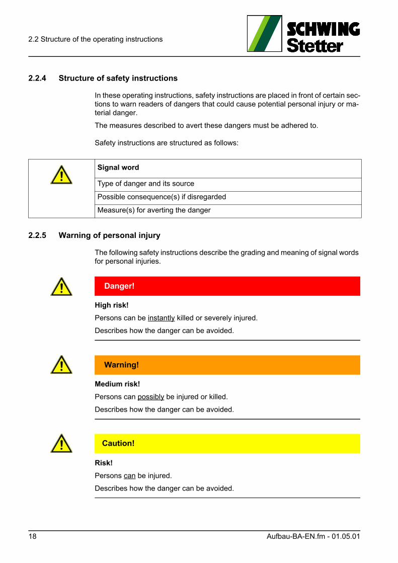
2.2.4 Structure of safety instructions
In these operating instructions, safety instructions are placed in front of certain sec-tions to warn readers of dangers that could cause potential personal injury or ma-terial danger.
The measures described to avert these dangers must be adhered to.
Safety instructions are structured as follows:
2.2.5 Warning of personal injury
The following safety instructions describe the grading and meaning of signal words for personal injuries.
GEFAHR! Danger!
High risk!
Persons can be instantly killed or severely injured.
Describes how the danger can be avoided.
WARNUNG! Warning!
Medium risk!
Persons can possibly be injured or killed.
Describes how the danger can be avoided.
VORSICHT! Caution!
Risk!
Persons can be injured.
Describes how the danger can be avoided.
Signal word
Type of danger and its source
Possible consequence(s) if disregarded
Measure(s) for averting the danger
18 Aufbau-BA-EN.fm - 01.05.01
2.2 Structure of the operating instructions
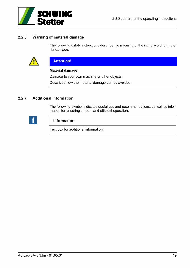
2.2.6 Warning of material damage
The following safety instructions describe the meaning of the signal word for mate-rial damage.
ACHTUNG! Attention!
Material damage!
Damage to your own machine or other objects.
Describes how the material damage can be avoided.
2.2.7 Additional information
The following symbol indicates useful tips and recommendations, as well as infor-mation for ensuring smooth and efficient operation.
Information
Text box for additional information.
Aufbau-BA-EN.fm - 01.05.01 19

2.2 Structure of the operating instructions
20 Aufbau-BA-EN.fm - 01.05.01

2.3 CE labelling
2.3 CE labelling
Machines brought into circulation from 01 January 1995 in the member states of the European Economic Area (EEA) must comply with the basic health and safety requirements of the relevant EC regulations.
The machine manufacturers confirm this by affixing a mark (Fig. 1) to the machine and by issuing a "Declaration of Conformity".
The CE mark is located on the base frame. The positions of the signs and labels can be found on a drawing in the ET catalogue.
Fig. 1 Communauté Européenne (European Community)
2.3.1 Declaration of conformity
SCHWING declares that the machine placed on the market in the European Eco-nomic Area complies with the relevant EC directives.
We confirm this by issuing a declaration of conformity and affixing a CE mark to the machine.
The original of each declaration of conformity is archived at SCHWING.
The customer receives a copy of this declaration in the national language, together with the delivery note or invoice.
The following pages each contain a sample of the declaration of conformity for truck-mounted concrete pumps (S) and stationary concrete pumps (SP).
Information
Machines placed on the market in the European Economic Area must comply with the valid guidelines.
This does not apply when the machines are placed on the market outside of the European Economic Area. If a certain machine design deviates from the design re-quired for the European Economic Area, SCHWING will not issue a declaration of conformity and the CE marking will not be affixed.
These machines may not be used in the European Economic Area!
CE-Konformität-EN.fm - 01.13.01 21

2.3 CE labelling
2.3.2 EC declaration of conformity for truck-mounted concrete pumps
According to EC Machine Directive 2006/42/EC appendix II A
We hereby declare that the machine specified below
complies with the following relevant provisions:
1 Complete list of the applied harmonised standards, see »Normative references in DIN EN 12001 conveying, spraying- and placing machines for concrete and mortar — Safe-ty requirements«
2 Complete list of the applied national standards and technical specifications, see »Ref-erences in DIN EN 12001 conveying, spraying and placing machines for concrete and mortar — Safety requirements«, as well as the SCHWING factory standard.
Person authorised, at the request of the market surveillance authorities, for the compilation of the relevant technical documents (declaration of conformity): CE-person authorised by SCHWING GmbH
This declaration loses its validity in the event of any unauthorised changes to the machine.
Designation of the machine:TRUCK-MOUNTED CONCRETE PUMP
Machine type: S
Machine no.
Machine Directive 2006 / 42 / EC
Low Voltage Directive 2014 / 35 / EU
EMC Directive 2014 / 30 / EU
Noise Emission Directive 2000 / 14 / EG
Applied harmonised standards1), especially:
DIN EN 12001, DIN EN ISO 12100, DIN EN 982, DIN EN 1088, DIN EN 13309, DIN EN 60204, DIN EN ISO 3744, DIN EN ISO 11688, DIN EN ISO 13849, DIN EN ISO 13850
Applied national standards and
technical specifications2), especially:DIN 24117, DIN 24118
Noise emission
Installed effective output
Measured sound power level
Guaranteed sound power level
P hydraulic = kW (diesel-hydraulic drive)
LWA measured = dB
LWA guaranteed = dB
Date/Signature by manufacturer
Information about signatory Management
22 CE-Konformität-EN.fm - 01.13.01
2.3 CE labelling
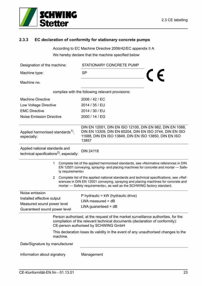
2.3.3 EC declaration of conformity for stationary concrete pumps
According to EC Machine Directive 2006/42/EC appendix II A
We hereby declare that the machine specified below
complies with the following relevant provisions:
1 Complete list of the applied harmonised standards, see »Normative references in DIN EN 12001 conveying, spraying- and placing machines for concrete and mortar — Safe-ty requirements«
2 Complete list of the applied national standards and technical specifications, see »Ref-erences in DIN EN 12001 conveying, spraying and placing machines for concrete and mortar — Safety requirements«, as well as the SCHWING factory standard.
Person authorised, at the request of the market surveillance authorities, for the compilation of the relevant technical documents (declaration of conformity): CE-person authorised by SCHWING GmbH
This declaration loses its validity in the event of any unauthorised changes to the machine.
Designation of the machine: STATIONARY CONCRETE PUMP
Machine type: SP
Machine no.
Machine Directive 2006 / 42 / EC
Low Voltage Directive 2014 / 35 / EU
EMC Directive 2014 / 30 / EU
Noise Emission Directive 2000 / 14 / EG
Applied harmonised standards1), especially:
DIN EN 12001, DIN EN ISO 12100, DIN EN 982, DIN EN 1088, DIN EN 13309, DIN EN 60204, DIN EN ISO 3744, DIN EN ISO 11688, DIN EN ISO 13849, DIN EN ISO 13850, DIN EN ISO 13857
Applied national standards and
technical specifications2), especially:DIN 24118
Noise emission
Installed effective output
Measured sound power level
Guaranteed sound power level
P hydraulic = kW (hydraulic drive)
LWA measured = dB
LWA guaranteed = dB
Date/Signature by manufacturer
Information about signatory Management
CE-Konformität-EN.fm - 01.13.01 23
2.3 CE labelling
2.3.4 Termination of the declaration of conformity
CE marking and declaration of conformity only apply to design and scope of deliv-ery of the machine delivered ex works.
Making changes to the machine without the approval of SCHWING, in addition to using accessories without the approval of SCHWING, shall cause both to lose their validity.
The competent supervisory authorities can decommission corresponding machines.
SCHWING is not liable for the consequences of the above manipulations. Operator and owner of the machine are responsible thereof.
24 CE-Konformität-EN.fm - 01.13.01
2.4 Theoretical service life of a machine
2.4 Theoretical service life of a machine
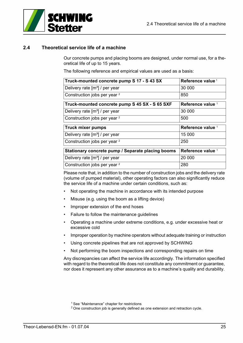
Our concrete pumps and placing booms are designed, under normal use, for a the-oretical life of up to 15 years.
The following reference and empirical values are used as a basis:
Please note that, in addition to the number of construction jobs and the delivery rate (volume of pumped material), other operating factors can also significantly reduce the service life of a machine under certain conditions, such as:
• Not operating the machine in accordance with its intended purpose
• Misuse (e.g. using the boom as a lifting device)
• Improper extension of the end hoses
• Failure to follow the maintenance guidelines
• Operating a machine under extreme conditions, e.g. under excessive heat or excessive cold
• Improper operation by machine operators without adequate training or instruction
• Using concrete pipelines that are not approved by SCHWING
• Not performing the boom inspections and corresponding repairs on time
Any discrepancies can affect the service life accordingly. The information specified with regard to the theoretical life does not constitute any commitment or guarantee, nor does it represent any other assurance as to a machine’s quality and durability.
1 See “Maintenance” chapter for restrictions2 One construction job is generally defined as one extension and retraction cycle.
Truck-mounted concrete pump S 17 - S 43 SX Reference value 1
Delivery rate [m³] / per year 30 000
Construction jobs per year 2 850
Truck-mounted concrete pump S 45 SX - S 65 SXF Reference value 1
Delivery rate [m³] / per year 30 000
Construction jobs per year 2 500
Truck mixer pumps Reference value 1
Delivery rate [m³] / per year 15 000
Construction jobs per year 2 250
Stationary concrete pump / Separate placing booms Reference value 1
Delivery rate [m³] / per year 20 000
Construction jobs per year 2 280
Theor-Lebensd-EN.fm - 01.07.04 25
2.4 Theoretical service life of a machine
Furthermore, timely compliance with the prescribed maintenance work and techni-cal safety inspections is also considered part of the intended use. See the “Mainte-nance” chapter and the safety manual in the appendix of these operating instructions.
In the event of damages of any kind, the entire machine must be inspected.
Contact SCHWING in the event of operations outside of the indicated reference values
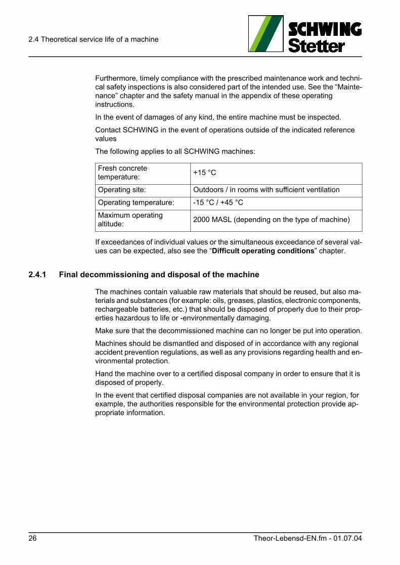
The following applies to all SCHWING machines:
If exceedances of individual values or the simultaneous exceedance of several val-ues can be expected, also see the “Difficult operating conditions” chapter.
2.4.1 Final decommissioning and disposal of the machine
The machines contain valuable raw materials that should be reused, but also ma-terials and substances (for example: oils, greases, plastics, electronic components, rechargeable batteries, etc.) that should be disposed of properly due to their prop-erties hazardous to life or -environmentally damaging.
Make sure that the decommissioned machine can no longer be put into operation.
Machines should be dismantled and disposed of in accordance with any regional accident prevention regulations, as well as any provisions regarding health and en-vironmental protection.
Hand the machine over to a certified disposal company in order to ensure that it is disposed of properly.
In the event that certified disposal companies are not available in your region, for example, the authorities responsible for the environmental protection provide ap-propriate information.
Fresh concrete temperature:
+15 °C
Operating site: Outdoors / in rooms with sufficient ventilation
Operating temperature: -15 °C / +45 °C
Maximum operating altitude:
2000 MASL (depending on the type of machine)
26 Theor-Lebensd-EN.fm - 01.07.04
2.5 Labelling SCHWING machines
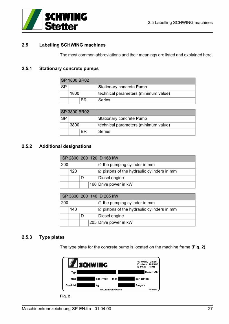
2.5 Labelling SCHWING machines
The most common abbreviations and their meanings are listed and explained here.
2.5.1 Stationary concrete pumps
2.5.2 Additional designations
2.5.3 Type plates
The type plate for the concrete pump is located on the machine frame (Fig. 2).
Fig. 2
SP 1800 BR02
SP Stationary concrete Pump
1800 technical parameters (minimum value)
BR Series
SP 3800 BR02
SP Stationary concrete Pump
3800 technical parameters (minimum value)
BR Series
SP 2800 200 120 D 168 kW
200 the pumping cylinder in mm
120 pistons of the hydraulic cylinders in mm
D Diesel engine
168 Drive power in kW
SP 3800 200 140 D 205 kW
200 the pumping cylinder in mm
140 pistons of the hydraulic cylinders in mm
D Diesel engine
205 Drive power in kW
Maschinenkennzeichnung-SP-EN.fm - 01.04.00 27

2.5 Labelling SCHWING machines
28 Maschinenkennzeichnung-SP-EN.fm - 01.04.00
2.6 Technical data for SP 1800 / 2800 CAT
2.6 Technical data for SP 1800 / 2800 CAT
Information
Power ratings are theoretical max. values!
WARNUNG! Warning!
The specified concrete pressures require suitable pumping line material!
(see “Operating the pumping line” on page 107)
Techn-Daten-SP-1800-2800-CAT-EN.fm - 01.01.00 29
2.6 Technical data for SP 1800 / 2800 CAT
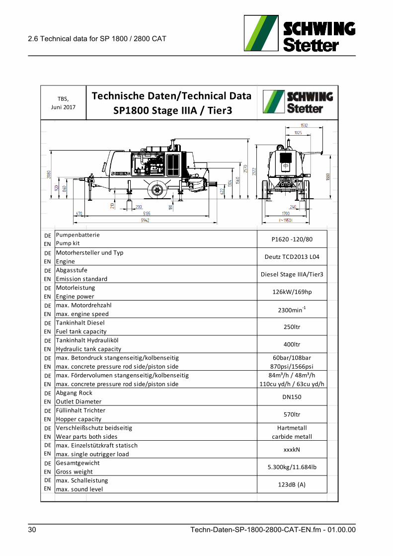
Technische Daten/Technical Data
SP1800 Stage IIIA / Tier3
DE
ENP1620 ‐120/80
DE
ENDeutz TCD2013 L04
DE
ENDiesel Stage IIIA/Tier3
DE
EN126kW/169hp
DE
EN2300min‐1
DE
EN250ltr
DE
EN400ltr
DE
EN
60bar/108bar
870psi/1566psi
DE
EN
84m³/h / 48m³/h
110cu yd/h / 63cu yd/h
DE
ENDN150
DE
EN570ltr
DE
EN
Hartmetall
carbide metall
DE
ENxxxkN
DE
EN5.300kg/11.684lb
DE
EN123dB (A)
Füllinhalt Trichter
Hopper capacity
Verschleißschutz beidseitig
Wear parts both sides
max. Einzelstützkraft statisch
max. single outrigger load
Gesamtgewicht
Gross weight
max. Schalleistung
max. sound level
Abgang Rock
Outlet Diameter
TBS,
Juni 2017
Pumpenbatterie
Pump kit
Motorhersteller und Typ
Engine
Abgasstufe
Emission standard
Motorleistung
Engine power
max. Motordrehzahl
max. engine speed
Tankinhalt Diesel
Fuel tank capacity
Tankinhalt Hydrauliköl
Hydraulic tank capacity
max. Betondruck stangenseitig/kolbenseitig
max. concrete pressure rod side/piston side
max. Fördervolumen stangenseitig/kolbenseitig
max. concrete pressure rod side/piston side
30 Techn-Daten-SP-1800-2800-CAT-EN.fm - 01.00.00
2.6 Technical data for SP 1800 / 2800 CAT
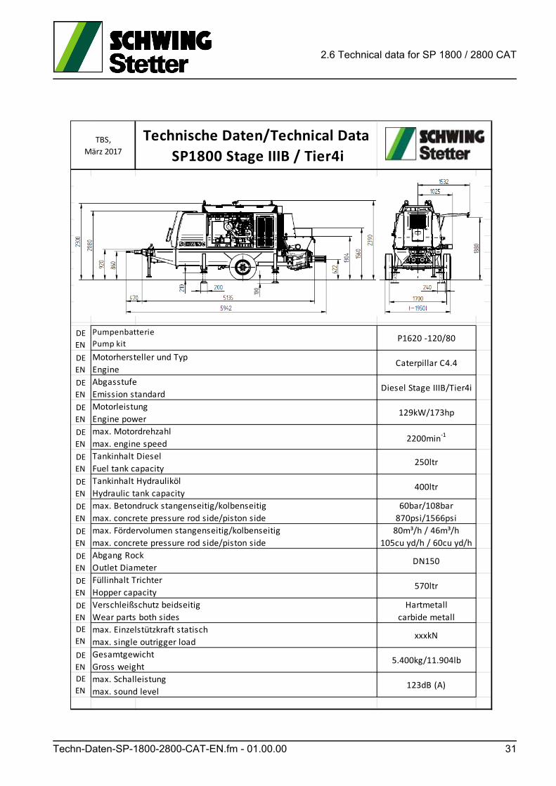
Technische Daten/Technical Data
SP1800 Stage IIIB / Tier4i
DE
ENP1620 ‐120/80
DE
ENCaterpillar C4.4
DE
ENDiesel Stage IIIB/Tier4i
DE
EN129kW/173hp
DE
EN2200min‐1
DE
EN250ltr
DE
EN400ltr
DE
EN
60bar/108bar
870psi/1566psi
DE
EN
80m³/h / 46m³/h
105cu yd/h / 60cu yd/h
DE
ENDN150
DE
EN570ltr
DE
EN
Hartmetall
carbide metall
DE
ENxxxkN
DE
EN5.400kg/11.904lb
DE
EN123dB (A)
Füllinhalt Trichter
Hopper capacity
Verschleißschutz beidseitig
Wear parts both sides
max. Einzelstützkraft statisch
max. single outrigger load
Gesamtgewicht
Gross weight
max. Schalleistung
max. sound level
Abgang Rock
Outlet Diameter
TBS,
März 2017
Pumpenbatterie
Pump kit
Motorhersteller und Typ
Engine
Abgasstufe
Emission standard
Motorleistung
Engine power
max. Motordrehzahl
max. engine speed
Tankinhalt Diesel
Fuel tank capacity
Tankinhalt Hydrauliköl
Hydraulic tank capacity
max. Betondruck stangenseitig/kolbenseitig
max. concrete pressure rod side/piston side
max. Fördervolumen stangenseitig/kolbenseitig
max. concrete pressure rod side/piston side
Techn-Daten-SP-1800-2800-CAT-EN.fm - 01.00.00 31
2.6 Technical data for SP 1800 / 2800 CAT
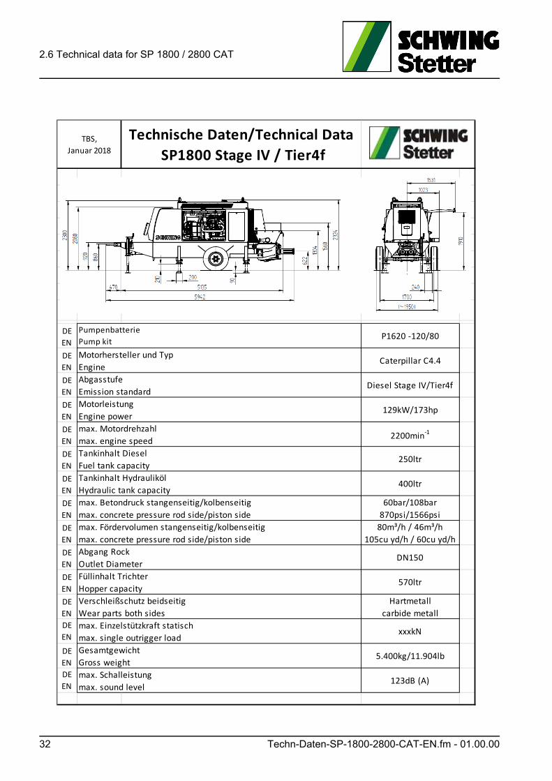
Technische Daten/Technical Data
SP1800 Stage IV / Tier4f
DE
ENP1620 ‐120/80
DE
ENCaterpillar C4.4
DE
ENDiesel Stage IV/Tier4f
DE
EN129kW/173hp
DE
EN2200min‐1
DE
EN250ltr
DE
EN400ltr
DE
EN
60bar/108bar
870psi/1566psi
DE
EN
80m³/h / 46m³/h
105cu yd/h / 60cu yd/h
DE
ENDN150
DE
EN570ltr
DE
EN
Hartmetall
carbide metall
DE
ENxxxkN
DE
EN5.400kg/11.904lb
DE
EN123dB (A)
Füllinhalt Trichter
Hopper capacity
Verschleißschutz beidseitig
Wear parts both sides
max. Einzelstützkraft statisch
max. single outrigger load
Gesamtgewicht
Gross weight
max. Schalleistung
max. sound level
Abgang Rock
Outlet Diameter
TBS,
Januar 2018
Pumpenbatterie
Pump kit
Motorhersteller und Typ
Engine
Abgasstufe
Emission standard
Motorleistung
Engine power
max. Motordrehzahl
max. engine speed
Tankinhalt Diesel
Fuel tank capacity
Tankinhalt Hydrauliköl
Hydraulic tank capacity
max. Betondruck stangenseitig/kolbenseitig
max. concrete pressure rod side/piston side
max. Fördervolumen stangenseitig/kolbenseitig
max. concrete pressure rod side/piston side
32 Techn-Daten-SP-1800-2800-CAT-EN.fm - 01.00.00
2.6 Technical data for SP 1800 / 2800 CAT
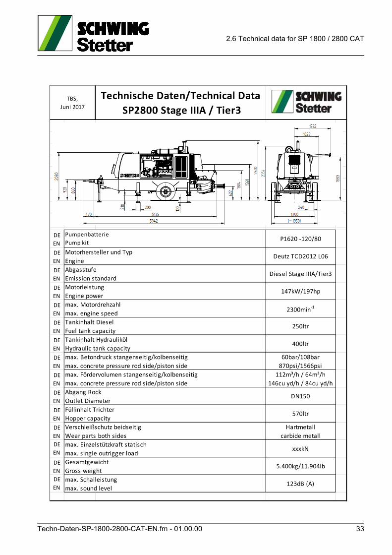
Technische Daten/Technical Data
SP2800 Stage IIIA / Tier3
DE
ENP1620 ‐120/80
DE
ENDeutz TCD2012 L06
DE
ENDiesel Stage IIIA/Tier3
DE
EN147kW/197hp
DE
EN2300min‐1
DE
EN250ltr
DE
EN400ltr
DE
EN
60bar/108bar
870psi/1566psi
DE
EN
112m³/h / 64m³/h
146cu yd/h / 84cu yd/h
DE
ENDN150
DE
EN570ltr
DE
EN
Hartmetall
carbide metall
DE
ENxxxkN
DE
EN5.400kg/11.904lb
DE
EN123dB (A)
Füllinhalt Trichter
Hopper capacity
Verschleißschutz beidseitig
Wear parts both sides
max. Einzelstützkraft statisch
max. single outrigger load
Gesamtgewicht
Gross weight
max. Schalleistung
max. sound level
Abgang Rock
Outlet Diameter
TBS,
Juni 2017
Pumpenbatterie
Pump kit
Motorhersteller und Typ
Engine
Abgasstufe
Emission standard
Motorleistung
Engine power
max. Motordrehzahl
max. engine speed
Tankinhalt Diesel
Fuel tank capacity
Tankinhalt Hydrauliköl
Hydraulic tank capacity
max. Betondruck stangenseitig/kolbenseitig
max. concrete pressure rod side/piston side
max. Fördervolumen stangenseitig/kolbenseitig
max. concrete pressure rod side/piston side
Techn-Daten-SP-1800-2800-CAT-EN.fm - 01.00.00 33
2.6 Technical data for SP 1800 / 2800 CAT
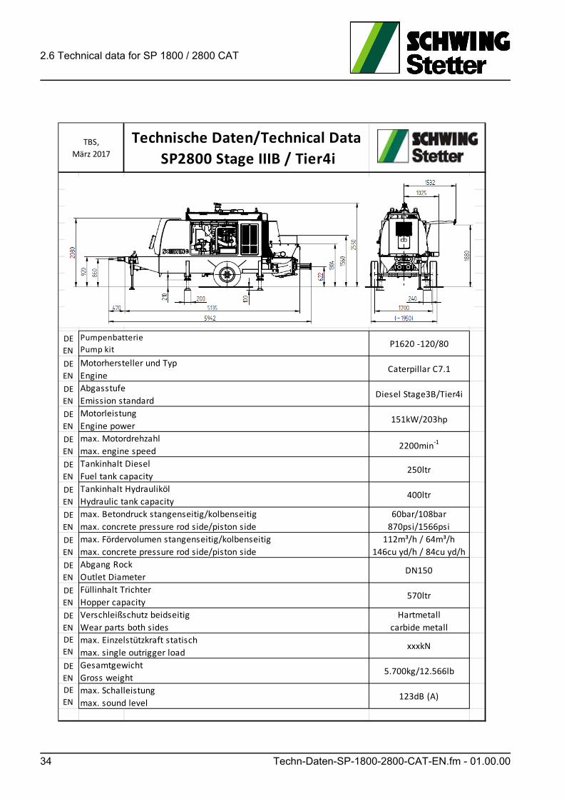
Technische Daten/Technical Data
SP2800 Stage IIIB / Tier4i
DE
ENP1620 ‐120/80
DE
ENCaterpillar C7.1
DE
ENDiesel Stage3B/Tier4i
DE
EN151kW/203hp
DE
EN2200min‐1
DE
EN250ltr
DE
EN400ltr
DE
EN
60bar/108bar
870psi/1566psi
DE
EN
112m³/h / 64m³/h
146cu yd/h / 84cu yd/h
DE
ENDN150
DE
EN570ltr
DE
EN
Hartmetall
carbide metall
DE
ENxxxkN
DE
EN5.700kg/12.566lb
DE
EN123dB (A)
Füllinhalt Trichter
Hopper capacity
Verschleißschutz beidseitig
Wear parts both sides
max. Einzelstützkraft statisch
max. single outrigger load
Gesamtgewicht
Gross weight
max. Schalleistung
max. sound level
Abgang Rock
Outlet Diameter
TBS,
März 2017
Pumpenbatterie
Pump kit
Motorhersteller und Typ
Engine
Abgasstufe
Emission standard
Motorleistung
Engine power
max. Motordrehzahl
max. engine speed
Tankinhalt Diesel
Fuel tank capacity
Tankinhalt Hydrauliköl
Hydraulic tank capacity
max. Betondruck stangenseitig/kolbenseitig
max. concrete pressure rod side/piston side
max. Fördervolumen stangenseitig/kolbenseitig
max. concrete pressure rod side/piston side
34 Techn-Daten-SP-1800-2800-CAT-EN.fm - 01.00.00
2.6 Technical data for SP 1800 / 2800 CAT
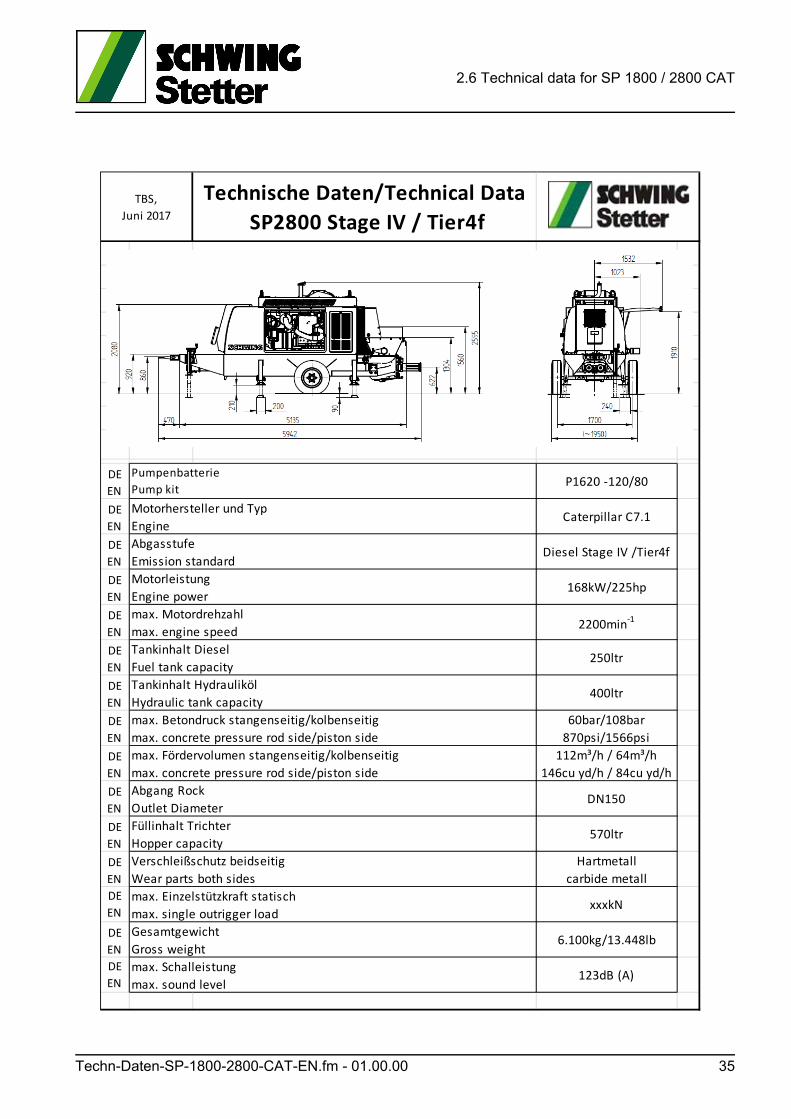
Technische Daten/Technical Data
SP2800 Stage IV / Tier4f
DE
ENP1620 ‐120/80
DE
ENCaterpillar C7.1
DE
ENDiesel Stage IV /Tier4f
DE
EN168kW/225hp
DE
EN2200min‐1
DE
EN250ltr
DE
EN400ltr
DE
EN
60bar/108bar
870psi/1566psi
DE
EN
112m³/h / 64m³/h
146cu yd/h / 84cu yd/h
DE
ENDN150
DE
EN570ltr
DE
EN
Hartmetall
carbide metall
DE
ENxxxkN
DE
EN6.100kg/13.448lb
DE
EN123dB (A)
Füllinhalt Trichter
Hopper capacity
Verschleißschutz beidseitig
Wear parts both sides
max. Einzelstützkraft statisch
max. single outrigger load
Gesamtgewicht
Gross weight
max. Schalleistung
max. sound level
Abgang Rock
Outlet Diameter
TBS,
Juni 2017
Pumpenbatterie
Pump kit
Motorhersteller und Typ
Engine
Abgasstufe
Emission standard
Motorleistung
Engine power
max. Motordrehzahl
max. engine speed
Tankinhalt Diesel
Fuel tank capacity
Tankinhalt Hydrauliköl
Hydraulic tank capacity
max. Betondruck stangenseitig/kolbenseitig
max. concrete pressure rod side/piston side
max. Fördervolumen stangenseitig/kolbenseitig
max. concrete pressure rod side/piston side
Techn-Daten-SP-1800-2800-CAT-EN.fm - 01.00.00 35

2.6 Technical data for SP 1800 / 2800 CAT
36 Techn-Daten-SP-1800-2800-CAT-EN.fm - 01.00.00
2.7 Assembly groups and designations for your machine SP1800 / 2800
2.7 Assembly groups and designations for your machine SP 1800 / 2800
This chapter contains an overview of the main assembly groups for your machine and their respective positions.
2.7.1 Machine description
The concrete pumps from series SP 1800/2800/3800/7000/7500 are oil-hydrauli-cally powered, two-cylinder piston pumps. They are designed for the pumping standard concrete through pipes.
Pumping other media, such as heavy concrete, lightweight concrete, screed and mortar, etc. is only permitted after consultation with SCHWING GmbH.
2.7.2 Transport option
The pump is mounted on a universally designed construction chassis frame with pneumatic tires. Other chassis frames are available on request.
2.7.3 Drive motors
The drive motor powers the pumps of the hydraulic system directly, without any in-termediate gear.
There are alternative diesel or electric motors available.
The diesel engine used as standard is liquid-cooled. It is optimised for exhaust gas and noise emission, as well as fuel consumption.
2.7.4 Hydraulic system
The hydraulic system operates in an open circuit.
An adjustable hydraulic pump is available for the drive of the differential cylinder.
The hydraulic accumulator and slewing cylinder are supplied via an additional ad-justable hydraulic pump.
Two fixed displacement pumps constantly pump hydraulic oil through the hydraulic oil cooler and filter.
Other fixed displacement pumps are available for the agitator and special equip-ment, such as the hydraulic outrigger, compressor, water pump and shut-off as-sembly.
The hydraulic accumulator facilitates the rapid switching of the rock valve.
Baugruppen-SP-1800-2800-EN.fm - 01.01.00 37
2.7 Assembly groups and designations for your machine SP 1800 / 2800
2.7.5 Concrete pump
The concrete pump is a two-cylinder piston pump with a rock valve.
The most important assembly groups (Fig. 3 Concrete pump) include:
1 Rock valve
2 Pumping cylinder and piston
3 Water box
4 Hydraulic drive cylinder
2.7.6 Rock valve
Like in a reciprocating piston engine, the pumping pistons in the two-cylinder piston pump are constantly changing their direction of motion.
The two pistons run counter to one another.
As the receding piston draws concrete out of the filling hopper, the advancing pis-ton pushes the previously drawn-in concrete into the pumping line.
At the same time, the rock valve (1) (Fig. 3 Concrete pump) swivels so that the "drawing" cylinder is connected to the filling hopper and the "pushing" cylinder to the pumping line.
By switching to “Suction” (reverse running), the concrete can be drawn from the pumping line and back into the filling hopper.
At the end positions, the hydraulic cylinders of the concrete pump and of the rock valve control hydraulic control valves, which coordinate the cylinder movements.
A hydraulic accumulator supports the rapid switching of the rock valve.
38 Baugruppen-SP-1800-2800-EN.fm - 01.01.00
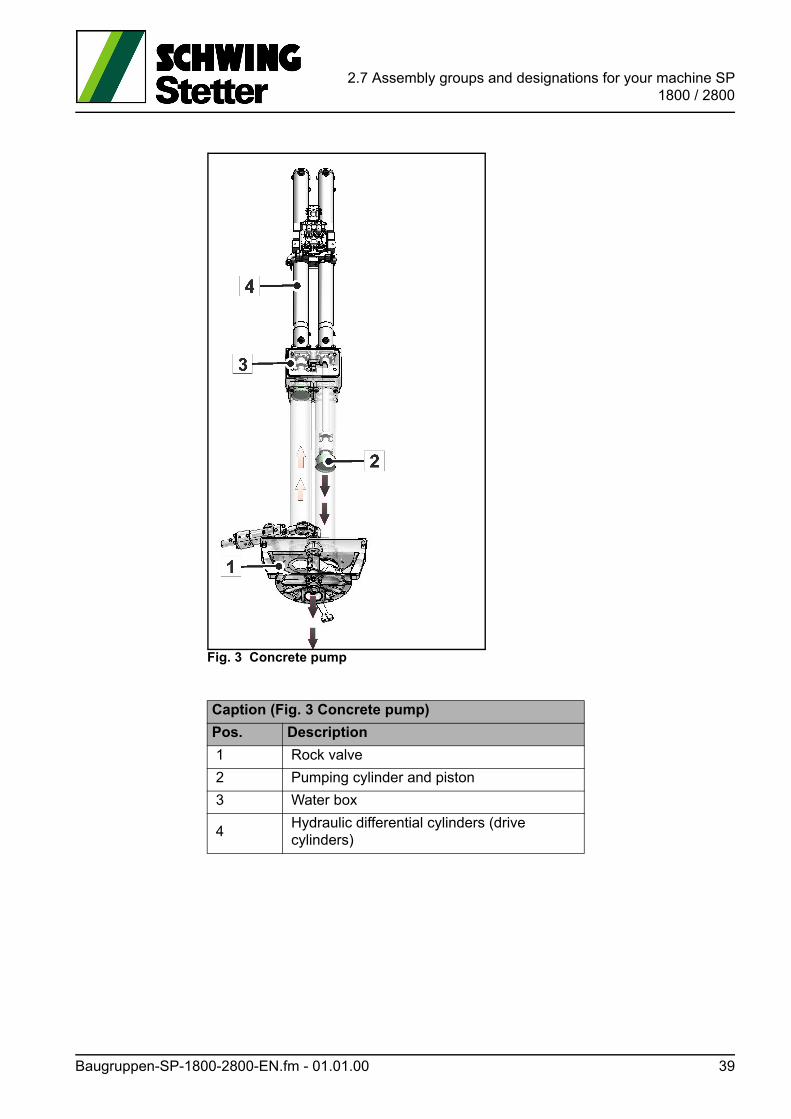
2.7 Assembly groups and designations for your machine SP1800 / 2800
Fig. 3 Concrete pump
Caption (Fig. 3 Concrete pump)
Pos. Description
1 Rock valve
2 Pumping cylinder and piston
3 Water box
4Hydraulic differential cylinders (drive cylinders)
Baugruppen-SP-1800-2800-EN.fm - 01.01.00 39
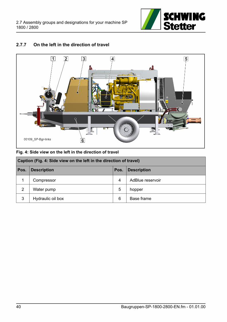
2.7 Assembly groups and designations for your machine SP 1800 / 2800
2.7.7 On the left in the direction of travel
Fig. 4: Side view on the left in the direction of travel
Caption (Fig. 4: Side view on the left in the direction of travel)
Pos. Description Pos. Description
1 Compressor 4 AdBlue reservoir
2 Water pump 5 hopper
3 Hydraulic oil box 6 Base frame
40 Baugruppen-SP-1800-2800-EN.fm - 01.01.00
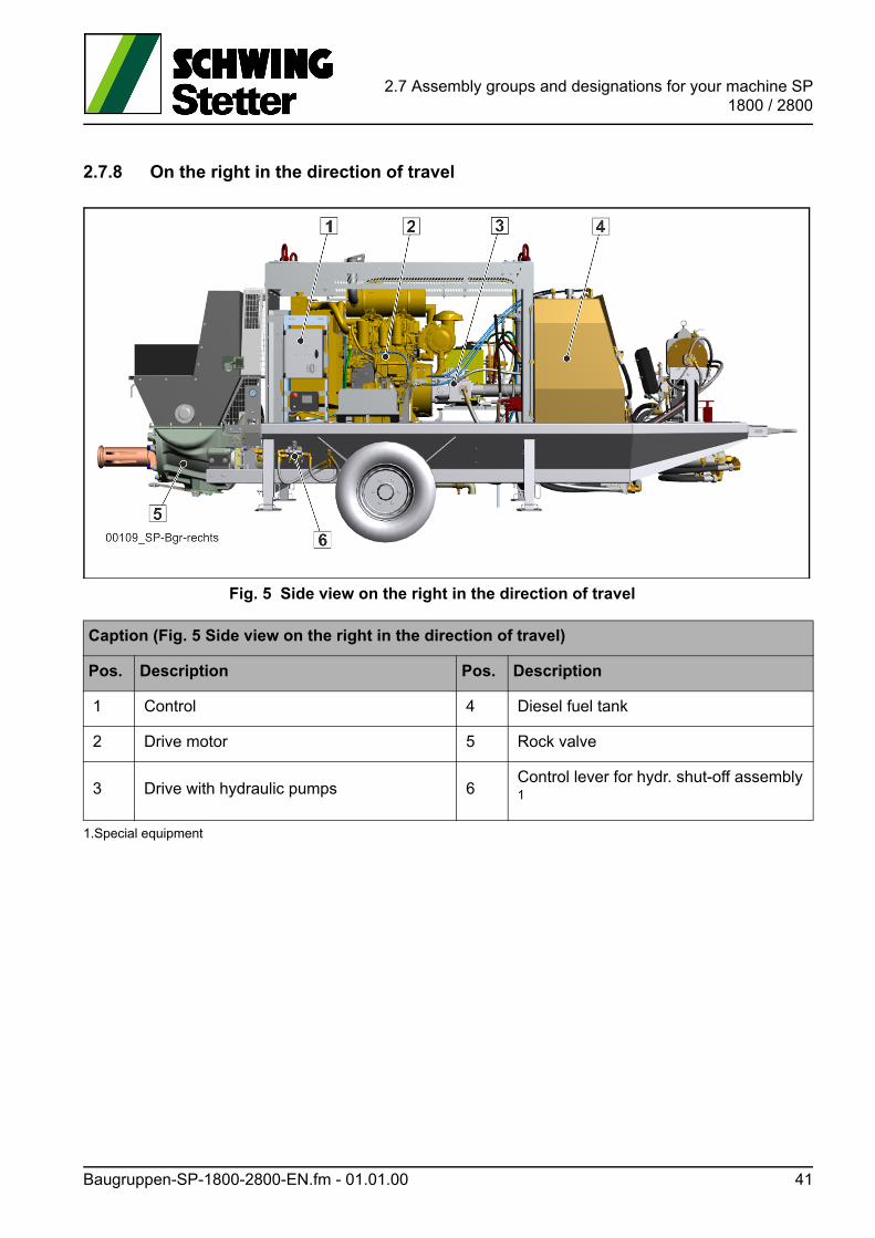
2.7 Assembly groups and designations for your machine SP1800 / 2800
2.7.8 On the right in the direction of travel
Fig. 5 Side view on the right in the direction of travel
Caption (Fig. 5 Side view on the right in the direction of travel)
Pos. Description Pos. Description
1 Control 4 Diesel fuel tank
2 Drive motor 5 Rock valve
3 Drive with hydraulic pumps 6Control lever for hydr. shut-off assembly 1
1.Special equipment
Baugruppen-SP-1800-2800-EN.fm - 01.01.00 41
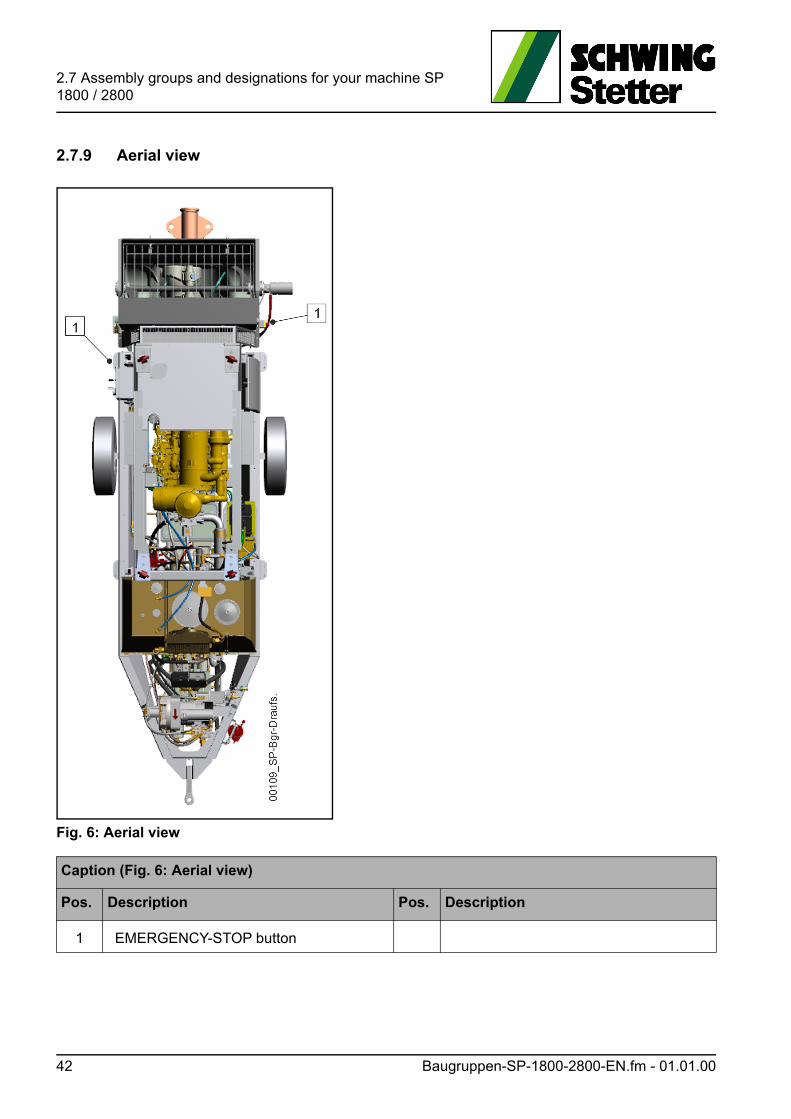
2.7 Assembly groups and designations for your machine SP 1800 / 2800
2.7.9 Aerial view
Fig. 6: Aerial view
Caption (Fig. 6: Aerial view)
Pos. Description Pos. Description
1 EMERGENCY-STOP button
42 Baugruppen-SP-1800-2800-EN.fm - 01.01.00
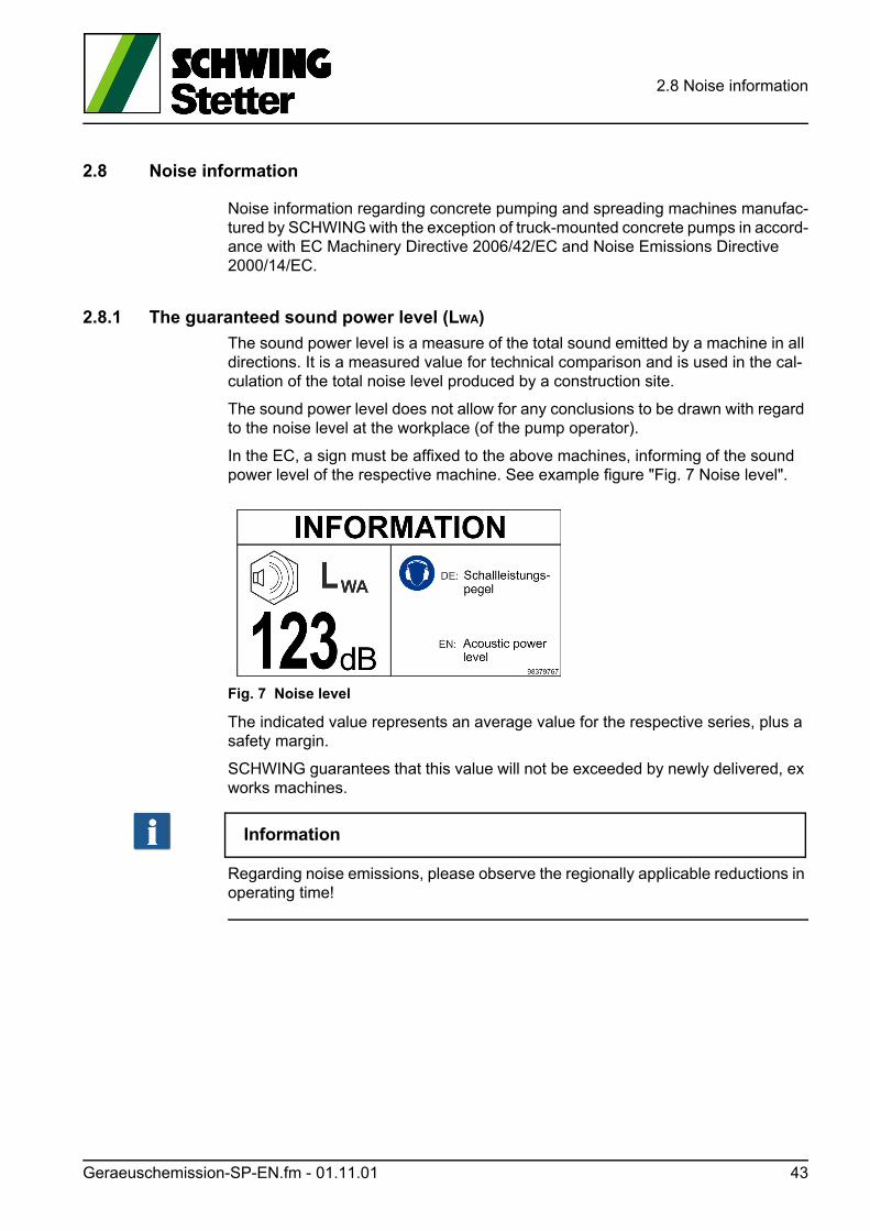
2.8 Noise information
2.8 Noise information
Noise information regarding concrete pumping and spreading machines manufac-tured by SCHWING with the exception of truck-mounted concrete pumps in accord-ance with EC Machinery Directive 2006/42/EC and Noise Emissions Directive 2000/14/EC.
2.8.1 The guaranteed sound power level (LWA)
The sound power level is a measure of the total sound emitted by a machine in all directions. It is a measured value for technical comparison and is used in the cal-culation of the total noise level produced by a construction site.
The sound power level does not allow for any conclusions to be drawn with regard to the noise level at the workplace (of the pump operator).
In the EC, a sign must be affixed to the above machines, informing of the sound power level of the respective machine. See example figure "Fig. 7 Noise level".
Fig. 7 Noise level
The indicated value represents an average value for the respective series, plus a safety margin.
SCHWING guarantees that this value will not be exceeded by newly delivered, ex works machines.
Information
Regarding noise emissions, please observe the regionally applicable reductions in operating time!
Geraeuschemission-SP-EN.fm - 01.11.01 43
2.8 Noise information
2.8.2 The highest sound pressure level (LpA)
The sound pressure level is a measure of the sound emissions in the workplace.
Machines equipped with a remote control unit as standard have no fixed workplace.
In this case, the Machine Directive prescribes that the highest sound pressure level be measured at a distance of 1 m from the machine surface and 1.6 m across the ground, which must be indicated in the operating instructions.
For machines without a remote control, the highest sound pressure level in the workplace is measured as above and given in the operating instructions.
VORSICHT! Caution!
Hearing can be damaged!
Personal hearing protection must always be worn when a sound pressure level of 80 dB(A) is exceeded.
Failure to observe this may be harmful to your health.
Close all hoods, covers etc. that are provided to insulate the noise!
44 Geraeuschemission-SP-EN.fm - 01.11.01
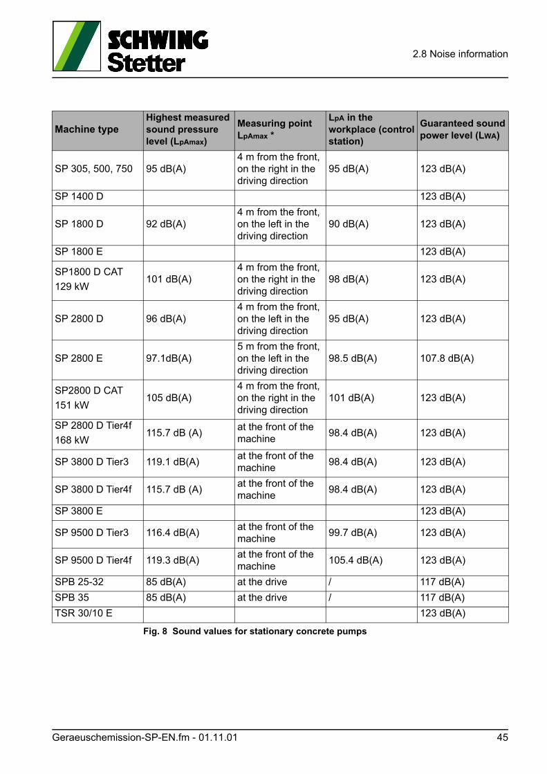
2.8 Noise information
Fig. 8 Sound values for stationary concrete pumps
Machine typeHighest measured sound pressurelevel (LpAmax)
Measuring point LpAmax *
LpA in the workplace (control station)
Guaranteed soundpower level (LWA)
SP 305, 500, 750 95 dB(A)4 m from the front, on the right in the driving direction
95 dB(A) 123 dB(A)
SP 1400 D 123 dB(A)
SP 1800 D 92 dB(A)4 m from the front, on the left in the driving direction
90 dB(A) 123 dB(A)
SP 1800 E 123 dB(A)
SP1800 D CAT
129 kW101 dB(A)
4 m from the front, on the right in the driving direction
98 dB(A) 123 dB(A)
SP 2800 D 96 dB(A)4 m from the front, on the left in the driving direction
95 dB(A) 123 dB(A)
SP 2800 E 97.1dB(A)5 m from the front, on the left in the driving direction
98.5 dB(A) 107.8 dB(A)
SP2800 D CAT
151 kW105 dB(A)
4 m from the front, on the right in the driving direction
101 dB(A) 123 dB(A)
SP 2800 D Tier4f
168 kW115.7 dB (A)
at the front of the machine
98.4 dB(A) 123 dB(A)
SP 3800 D Tier3 119.1 dB(A)at the front of the machine
98.4 dB(A) 123 dB(A)
SP 3800 D Tier4f 115.7 dB (A)at the front of the machine
98.4 dB(A) 123 dB(A)
SP 3800 E 123 dB(A)
SP 9500 D Tier3 116.4 dB(A)at the front of the machine
99.7 dB(A) 123 dB(A)
SP 9500 D Tier4f 119.3 dB(A)at the front of the machine
105.4 dB(A) 123 dB(A)
SPB 25-32 85 dB(A) at the drive / 117 dB(A)
SPB 35 85 dB(A) at the drive / 117 dB(A)
TSR 30/10 E 123 dB(A)
Geraeuschemission-SP-EN.fm - 01.11.01 45
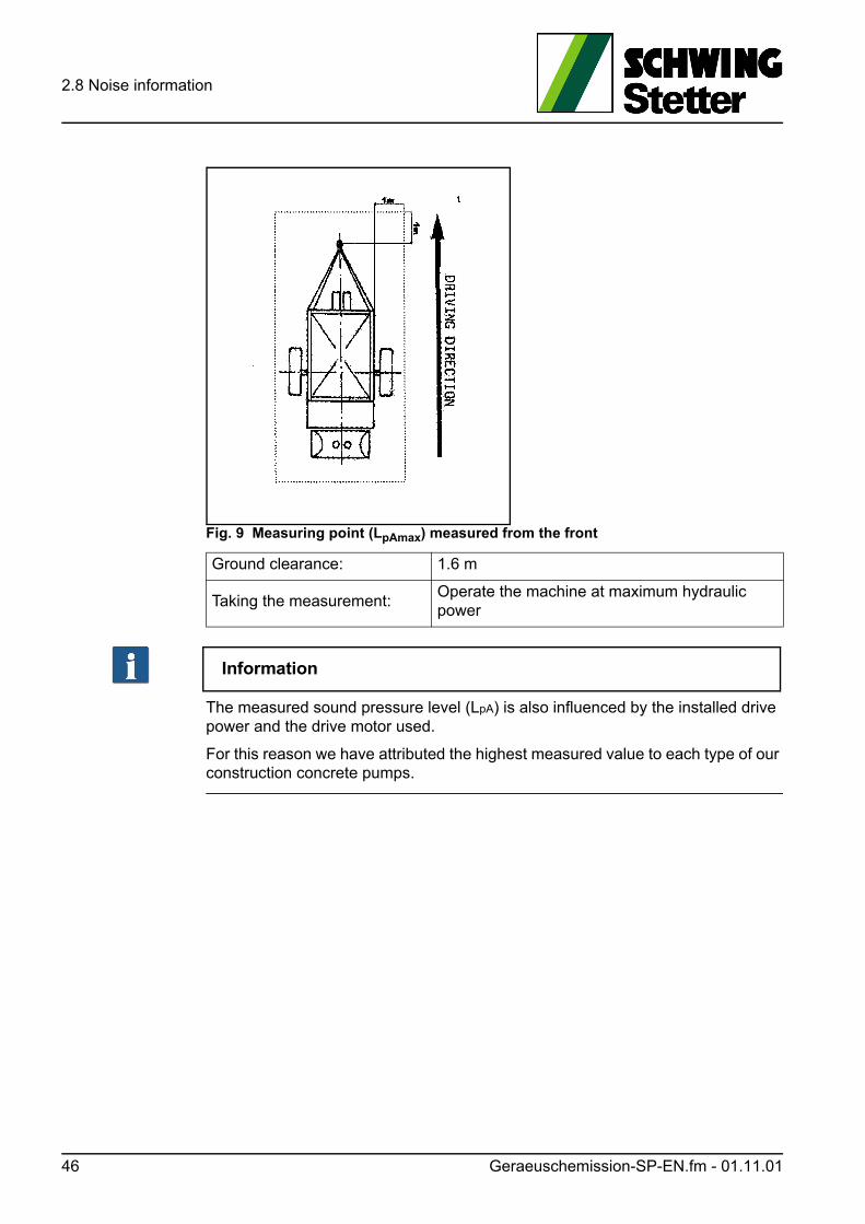
2.8 Noise information
Fig. 9 Measuring point (LpAmax) measured from the front
Information
The measured sound pressure level (LpA) is also influenced by the installed drive power and the drive motor used.
For this reason we have attributed the highest measured value to each type of our construction concrete pumps.
Ground clearance: 1.6 m
Taking the measurement:Operate the machine at maximum hydraulic power
46 Geraeuschemission-SP-EN.fm - 01.11.01
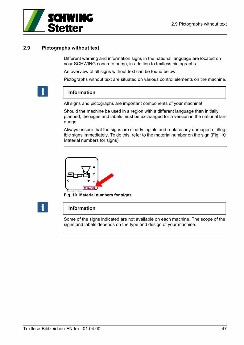
2.9 Pictographs without text
2.9 Pictographs without text
Different warning and information signs in the national language are located on your SCHWING concrete pump, in addition to textless pictographs.
An overview of all signs without text can be found below.
Pictographs without text are situated on various control elements on the machine.
Information
All signs and pictographs are important components of your machine!
Should the machine be used in a region with a different language than initially planned, the signs and labels must be exchanged for a version in the national lan-guage.
Always ensure that the signs are clearly legible and replace any damaged or illeg-ible signs immediately. To do this, refer to the material number on the sign (Fig. 10 Material numbers for signs).
Fig. 10 Material numbers for signs
Information
Some of the signs indicated are not available on each machine. The scope of the signs and labels depends on the type and design of your machine.
Textlose-Bildzeichen-EN.fm - 01.04.00 47
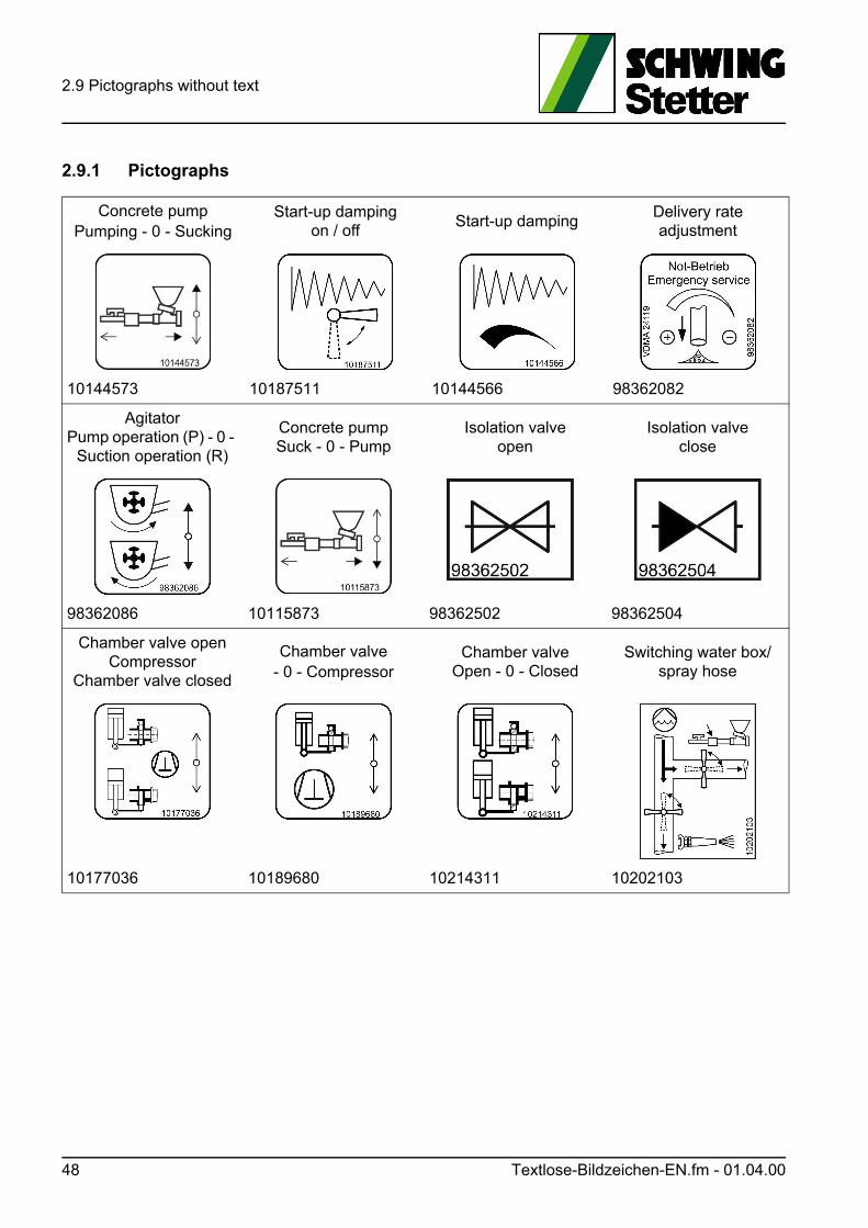
2.9 Pictographs without text
2.9.1 Pictographs
Concrete pumpPumping - 0 - Sucking
Start-up dampingon / off
Start-up dampingDelivery rateadjustment
10144573 10187511 10144566 98362082
AgitatorPump operation (P) - 0 -
Suction operation (R)
Concrete pumpSuck - 0 - Pump
Isolation valveopen
Isolation valveclose
98362086 10115873 98362502 98362504
Chamber valve openCompressor
Chamber valve closed
Chamber valve- 0 - Compressor
Chamber valveOpen - 0 - Closed
Switching water box/spray hose
10177036 10189680 10214311 10202103
48 Textlose-Bildzeichen-EN.fm - 01.04.00
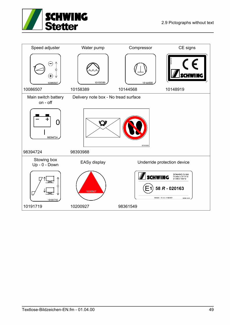
2.9 Pictographs without text
Speed adjuster Water pump Compressor CE signs
10086507 10158389 10144568 10148919
Main switch batteryon - off
Delivery note box - No tread surface
98394724 98393988
Stowing boxUp - 0 - Down
EASy display Underride protection device
10191719 10200927 98361549
Textlose-Bildzeichen-EN.fm - 01.04.00 49
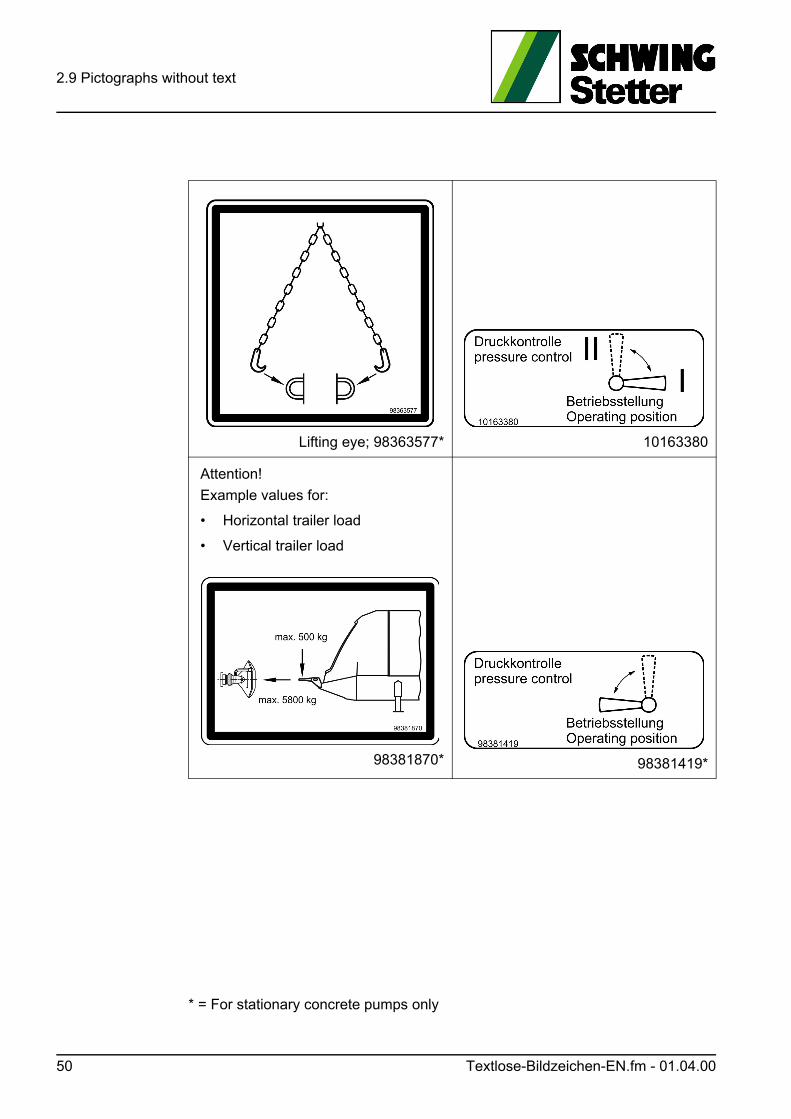
2.9 Pictographs without text
* = For stationary concrete pumps only
Lifting eye; 98363577* 10163380
Attention!
Example values for:
• Horizontal trailer load
• Vertical trailer load
98381870* 98381419*
50 Textlose-Bildzeichen-EN.fm - 01.04.00
2.10 Control, warning and steering elements SP 1800 / 2800
2.10 Control, warning and steering elements SP 1800 / 2800
This chapter clearly describes the positions of the control, warning and steering el-ements on your machine.
2.10.1 Concrete pump control
The concrete pump control lets the operator control all functions of the concrete pump electronically. The system includes the control panel and cable remote con-trol, as well as the optional radio control.
Connect the cable remote control to the power outlet (11) (Fig. 11).
If the machine is operated with the radio remote control or operator keyboard, insert the bypass plug into the power outlet (11).
The control panel is equipped with the following elements.
Kontroll-Warn-Steuerelemente-SP-1800-2800-EN.fm - 01.03.00 51
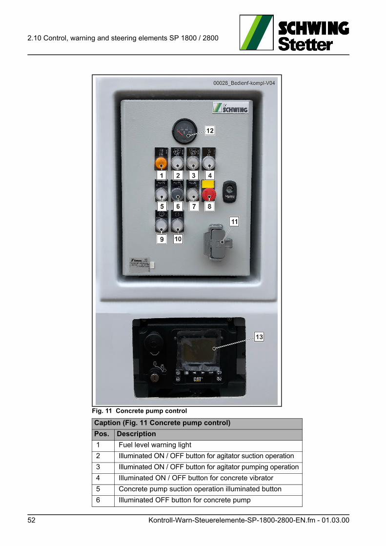
2.10 Control, warning and steering elements SP 1800 / 2800
Fig. 11 Concrete pump control
Caption (Fig. 11 Concrete pump control)
Pos. Description
1 Fuel level warning light
2 Illuminated ON / OFF button for agitator suction operation
3 Illuminated ON / OFF button for agitator pumping operation
4 Illuminated ON / OFF button for concrete vibrator
5 Concrete pump suction operation illuminated button
6 Illuminated OFF button for concrete pump
52 Kontroll-Warn-Steuerelemente-SP-1800-2800-EN.fm - 01.03.00
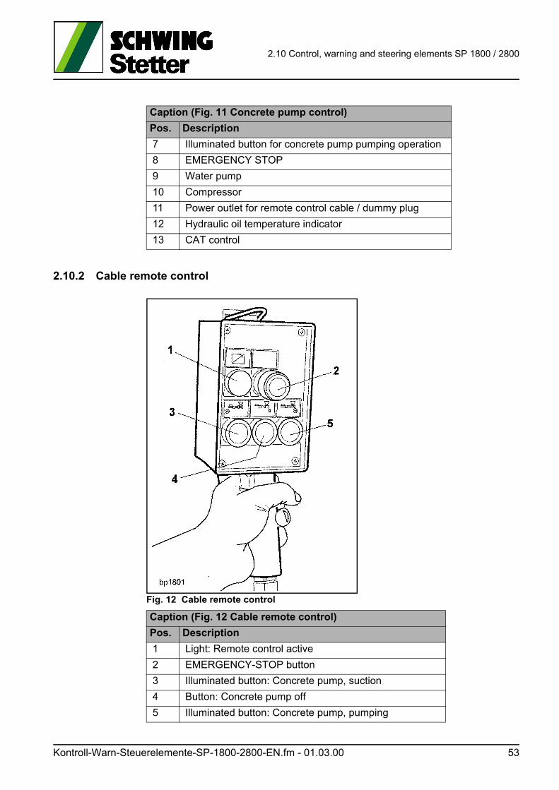
2.10 Control, warning and steering elements SP 1800 / 2800
2.10.2 Cable remote control
Fig. 12 Cable remote control
7 Illuminated button for concrete pump pumping operation
8 EMERGENCY STOP
9 Water pump
10 Compressor
11 Power outlet for remote control cable / dummy plug
12 Hydraulic oil temperature indicator
13 CAT control
Caption (Fig. 11 Concrete pump control)
Pos. Description
Caption (Fig. 12 Cable remote control)
Pos. Description
1 Light: Remote control active
2 EMERGENCY-STOP button
3 Illuminated button: Concrete pump, suction
4 Button: Concrete pump off
5 Illuminated button: Concrete pump, pumping
Kontroll-Warn-Steuerelemente-SP-1800-2800-EN.fm - 01.03.00 53

2.10 Control, warning and steering elements SP 1800 / 2800
2.10.3 CAT control (IOPU control panel)
Information
Note that regeneration occurs automatically with the SP 1800 CAT TIER 4i and 2800 TIER 4f.
Fig. 13 IOPU Tier 4i, Stage IIIB - CAT control panel
Caption (Fig. 13)
Pos. Description
1Yellow "fault/warning indicator" light indicates errors reported via the CAN bus.
2 Red "fault/warning indicator" light indicates a shutdown reported via the CAN bus.
3"Regeneration request" button: The operator can use this button to send a regeneration request to the motor for the purpose of carrying out an active regeneration, see Chapter (2.10.5).
4"Regeneration suppression" button: The operator can use this button to send a signal to the motor to instruct it to suppress an active regeneration, see Chapter (2.10.5).
5"Enter" button: The operator can use this button to select settings in the settings screen for adjustments and saving.
6"Right arrow" button: The operator can use this button to scroll through error lists in measurement display screens and through settings in the settings screen.
54 Kontroll-Warn-Steuerelemente-SP-1800-2800-EN.fm - 01.03.00
2.10 Control, warning and steering elements SP 1800 / 2800
7IOPU control station connector: Connects the IOPU control station to the motor wiring harness.
8"Left arrow" button: The operator can use this button to scroll through error lists in measurement display screens and through settings in the settings screen.
9"Back" button: The operator can use this button to move between various screens and to quit the displayed settings without saving.
10
"Speed reduction" button: The operator can use this button to reduce the speed of the motor via the CAN bus by using TSC1. Pressing the button displays the desired motor speed screen to the operator. ("Reduction step" = 25 rpm, adjustable standard value; return time "Hold" = 200 rpm, adjustable standard value)
11
"Speed increase" button: The operator can use this button to increase the speed of the motor via the CAN bus by using TSC1. Pressing the button displays the desired motor speed screen to the operator. ("Increase step" = 25 rpm, adjustable standard value; ramp-up time "Hold" = 200 rpm, adjustable standard value)
12Key-operated switch: The operator starts the motor by turning the key to the "Start" position.
13"Motor shutdown via control panel" button. Switch actuation by the operator. To shut down the motor, the switch must be pushed in. Pulling out the switch causes the release for starting via the key-operated switch.
Caption (Fig. 13)
Pos. Description
Kontroll-Warn-Steuerelemente-SP-1800-2800-EN.fm - 01.03.00 55

2.10 Control, warning and steering elements SP 1800 / 2800
2.10.4 TSC function
The TSC function allows you to change and save the motor’s rotational speed on the control panel.
The function is the equivalent of a cruise control in a passenger vehicle.
As long as the control is active, the configured value will remain saved on the clip-board and can be restored after any potential interruptions by using the “TSC” but-ton (14).
As soon as the control is switched off using the key-operated switch (12), that saved value is deleted.
To configure the rotational speed, enable the TSC function by pressing button (14) once.
The current rotational speed is then shown on the display.
Change the rotational speed with the help of buttons (10) and (11), see caption for (Fig. 13).
Fig. 14 IOPU Tier 4f, Stage IV - control panel
Caption (Fig. 14)
Pos. Description
14 TSC function ON
15 TSC function OFF
56 Kontroll-Warn-Steuerelemente-SP-1800-2800-EN.fm - 01.03.00

2.10 Control, warning and steering elements SP 1800 / 2800
2.10.5 “Regeneration” instructions
Information
Engine power failure!
Observe the possible automatic regenerations of the diesel engine.
The motor speed can be lowered automatically or the diesel engine will be switched off in pumping operation.
Carry out the regeneration in due time according to the motor manufacturer’s spec-ifications.
ACHTUNG! Attention!
Machine parts or the entire machine can be destroyed.
Follow the following description carefully for the manual “regeneration”.
Implementation of regeneration for Caterpillar motor CAT C7.1 Acert Tier 4i.
5. The degree of clogging is displayed on the Caterpillar display, item 0 (Fig. 13) (bar graph or percentage).
6. Automatic regeneration of the diesel particle filter (DPF) can already be car-ried out from a degree of clogging of 30%.
7. Automatic regeneration of the diesel particle filter (DPF) is required starting at a degree of clogging of 80%; a control light appears on the display.
8. At a degree of clogging of 100%, the following lights up on the display.
9. Further use without regeneration will result in the motor performance being independently reduced.
10. If the degree of clogging increases further, then a warning buzzer sounds in addition to the indicators.
11. After the warning buzzer has been sounding for 5 minutes, the motor switch-es to idling speed.
12. Within the next 10 minutes of idling, regeneration must be carried out.
Kontroll-Warn-Steuerelemente-SP-1800-2800-EN.fm - 01.03.00 57
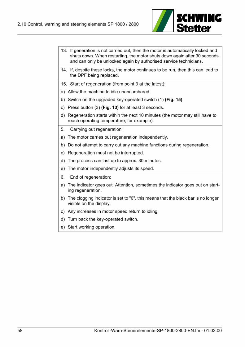
2.10 Control, warning and steering elements SP 1800 / 2800
13. If generation is not carried out, then the motor is automatically locked and shuts down. When restarting, the motor shuts down again after 30 seconds and can only be unlocked again by authorised service technicians.
14. If, despite these locks, the motor continues to be run, then this can lead to the DPF being replaced.
15. Start of regeneration (from point 3 at the latest):
a) Allow the machine to idle unencumbered.
b) Switch on the upgraded key-operated switch (1) (Fig. 15).
c) Press button (3) (Fig. 13) for at least 3 seconds.
d) Regeneration starts within the next 10 minutes (the motor may still have to reach operating temperature, for example).
5. Carrying out regeneration:
a) The motor carries out regeneration independently.
b) Do not attempt to carry out any machine functions during regeneration.
c) Regeneration must not be interrupted.
d) The process can last up to approx. 30 minutes.
e) The motor independently adjusts its speed.
6. End of regeneration:
a) The indicator goes out. Attention, sometimes the indicator goes out on start-ing regeneration.
b) The clogging indicator is set to "0", this means that the black bar is no longer visible on the display.
c) Any increases in motor speed return to idling.
d) Turn back the key-operated switch.
e) Start working operation.
58 Kontroll-Warn-Steuerelemente-SP-1800-2800-EN.fm - 01.03.00
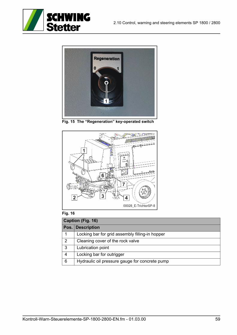
2.10 Control, warning and steering elements SP 1800 / 2800
Fig. 15 The “Regeneration” key-operated switch
Fig. 16
Caption (Fig. 16)
Pos. Description
1 Locking bar for grid assembly filling-in hopper
2 Cleaning cover of the rock valve
3 Lubrication point
4 Locking bar for outrigger
6 Hydraulic oil pressure gauge for concrete pump
Kontroll-Warn-Steuerelemente-SP-1800-2800-EN.fm - 01.03.00 59
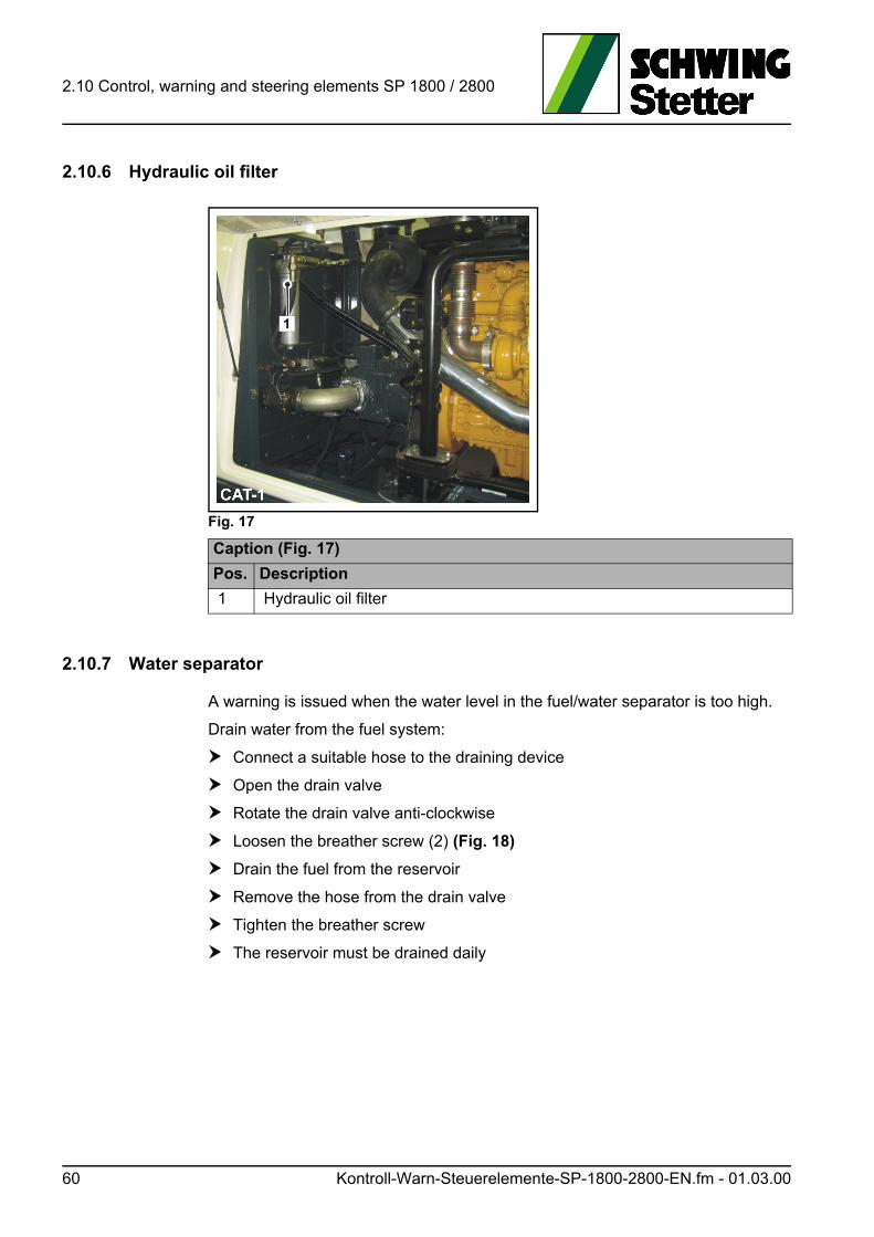
2.10 Control, warning and steering elements SP 1800 / 2800
2.10.6 Hydraulic oil filter
Fig. 17
2.10.7 Water separator
A warning is issued when the water level in the fuel/water separator is too high.
Drain water from the fuel system:
Connect a suitable hose to the draining device
Open the drain valve
Rotate the drain valve anti-clockwise
Loosen the breather screw (2) (Fig. 18)
Drain the fuel from the reservoir
Remove the hose from the drain valve
Tighten the breather screw
The reservoir must be drained daily
Caption (Fig. 17)
Pos. Description
1 Hydraulic oil filter
60 Kontroll-Warn-Steuerelemente-SP-1800-2800-EN.fm - 01.03.00
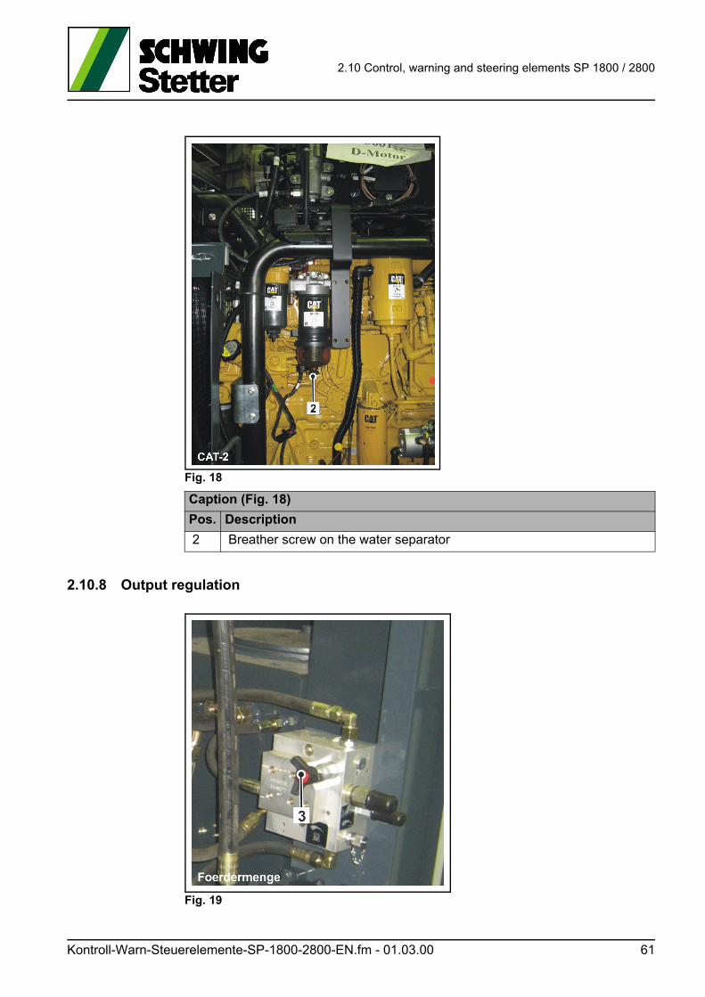
2.10 Control, warning and steering elements SP 1800 / 2800
Fig. 18
2.10.8 Output regulation
Fig. 19
Caption (Fig. 18)
Pos. Description
2 Breather screw on the water separator
Kontroll-Warn-Steuerelemente-SP-1800-2800-EN.fm - 01.03.00 61
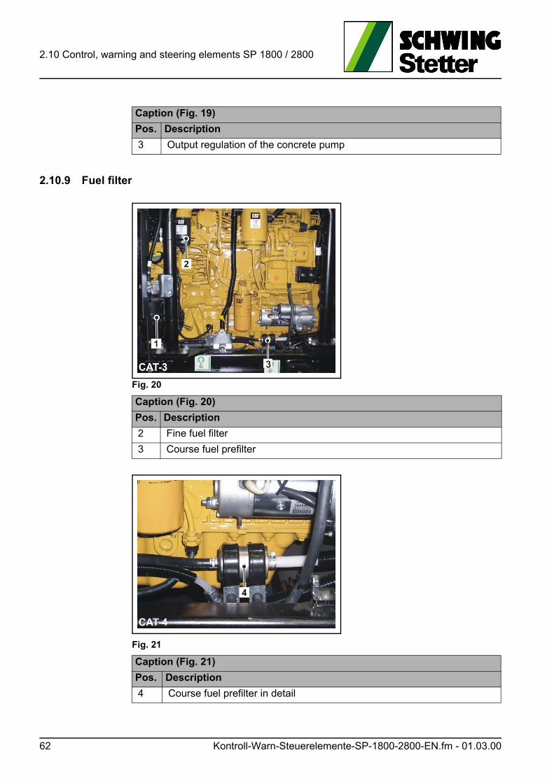
2.10 Control, warning and steering elements SP 1800 / 2800
2.10.9 Fuel filter
Fig. 20
Fig. 21
Caption (Fig. 19)
Pos. Description
3 Output regulation of the concrete pump
Caption (Fig. 20)
Pos. Description
2 Fine fuel filter
3 Course fuel prefilter
Caption (Fig. 21)
Pos. Description
4 Course fuel prefilter in detail
62 Kontroll-Warn-Steuerelemente-SP-1800-2800-EN.fm - 01.03.00
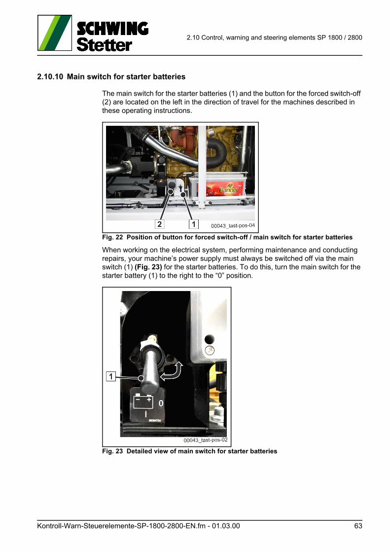
2.10 Control, warning and steering elements SP 1800 / 2800
2.10.10 Main switch for starter batteries
The main switch for the starter batteries (1) and the button for the forced switch-off (2) are located on the left in the direction of travel for the machines described in these operating instructions.
Fig. 22 Position of button for forced switch-off / main switch for starter batteries
When working on the electrical system, performing maintenance and conducting repairs, your machine’s power supply must always be switched off via the main switch (1) (Fig. 23) for the starter batteries. To do this, turn the main switch for the starter battery (1) to the right to the “0” position.
Fig. 23 Detailed view of main switch for starter batteries
Kontroll-Warn-Steuerelemente-SP-1800-2800-EN.fm - 01.03.00 63
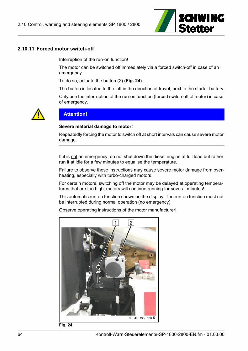
2.10 Control, warning and steering elements SP 1800 / 2800
2.10.11 Forced motor switch-off
Interruption of the run-on function!
The motor can be switched off immediately via a forced switch-off in case of an emergency.
To do so, actuate the button (2) (Fig. 24).
The button is located to the left in the direction of travel, next to the starter battery.
Only use the interruption of the run-on function (forced switch-off of motor) in case of emergency.
ACHTUNG! Attention!
Severe material damage to motor!
Repeatedly forcing the motor to switch off at short intervals can cause severe motor damage.
If it is not an emergency, do not shut down the diesel engine at full load but rather run it at idle for a few minutes to equalise the temperature.
Failure to observe these instructions may cause severe motor damage from over-heating, especially with turbo-charged motors.
For certain motors, switching off the motor may be delayed at operating tempera-tures that are too high; motors will continue running for several minutes!
This automatic run-on function shown on the display. The run-on function must not be interrupted during normal operation (no emergency).
Observe operating instructions of the motor manufacturer!
Fig. 24
64 Kontroll-Warn-Steuerelemente-SP-1800-2800-EN.fm - 01.03.00
Trennblatt_Kapitel-Betrieb-EN
3 Operation
This chapter describes:
• All of your machine’s operating modes
• Safe and proper handing
• Safe and economical operation
.fm 65

3 Operation
66 Trennblatt_Kapitel-Betrieb-EN.fm - 01.00.00
3.1 Driving operation PLC
3.1 Driving operation PLC
Information
Stationary concrete pumps may only be driven in open road traffic with the appro-priate approval.
The equipment for the concrete pump with a chassis frame approved for road traffic may require an amendment to the operating instructions.
This amendment is provided as a separate document, as needed.
The driver of the tractor must have the necessary driving licence. Observe the reg-ulation in the country of use.
Make sure the machine is roadworthy before driving. This includes:
• The air pressure of the tyres according to the table
• The lighting is working properly (only for 80 km/h chassis frame)
• The braking system is working properly (only for 80 km/h chassis frame)
• Sound chassis frame maintenance
• Equipment and accessories are stored securely
3.1.1 Environmental protection and accident prevention
• Check for leaks in the reservoirs.
• Empty fuel tank and oil box, if necessary.
• Secure the outrigger against extending on its own.
3.1.2 Air pressure table
Tyre size Air pressure (bar/psi)
6.50 R 16 C 5.0 / 70
7.00 R 16 6.0 / 85
7.50 R 16 6.5 / 90
8.25 R 16 7.0 / 95
8.50 R 17.5 6.0 / 85
9.00-20.14 PR 7.75 / 110
10 R 22.5 7.0 / 95
Fahrbetrieb-SP-EN.fm - 01.06.01 67
3.1 Driving operation PLC
3.1.3 Transporting people and goods
Stationary concrete pumps are work machines.
They may not be used for the transport of people and goods.
This also applies for the transport of concrete in the filling-in hopper of the concrete pump.
Unfavourable weight distribution worsens vehicle handling and can lead to damage to the chassis frame and structure.
Accessories essential to the work application are excluded from the prohibition. Ac-cessories must be stowed in a roadworthy manner. The permissible total weight and the maximum permissible axle load must not be exceeded.
275 / 70 R 22.5 7.0 / 102
445 / 45R 19.5 9.0 / 130
Tyre size Air pressure (bar/psi)
68 Fahrbetrieb-SP-EN.fm - 01.06.01
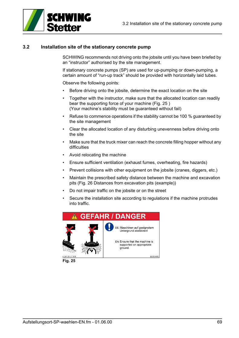
3.2 Installation site of the stationary concrete pump
3.2 Installation site of the stationary concrete pump
SCHWING recommends not driving onto the jobsite until you have been briefed by an “instructor” authorised by the site management.
If stationary concrete pumps (SP) are used for up-pumping or down-pumping, a certain amount of “run-up track” should be provided with horizontally laid tubes.
Observe the following points:
• Before driving onto the jobsite, determine the exact location on the site
• Together with the instructor, make sure that the allocated location can readily bear the supporting force of your machine (Fig. 25 )(Your machine’s stability must be guaranteed without fail)
• Refuse to commence operations if the stability cannot be 100 % guaranteed by the site management
• Clear the allocated location of any disturbing unevenness before driving onto the site
• Make sure that the truck mixer can reach the concrete filling hopper without any difficulties
• Avoid relocating the machine
• Ensure sufficient ventilation (exhaust fumes, overheating, fire hazards)
• Prevent collisions with other equipment on the jobsite (cranes, diggers, etc.)
• Maintain the prescribed safety distance between the machine and excavation pits (Fig. 26 Distances from excavation pits (example))
• Do not impair traffic on the jobsite or on the street
• Secure the installation site according to regulations if the machine protrudes into traffic.
Fig. 25
Aufstellungsort-SP-waehlen-EN.fm - 01.06.00 69
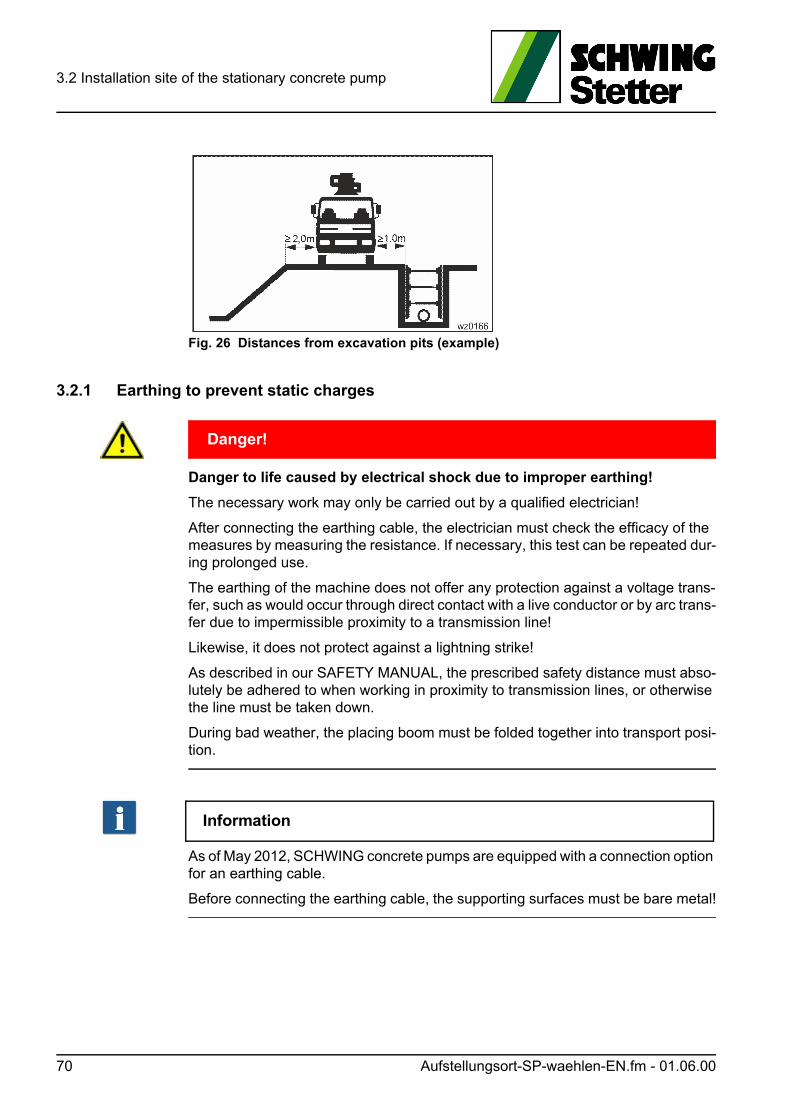
3.2 Installation site of the stationary concrete pump
Fig. 26 Distances from excavation pits (example)
3.2.1 Earthing to prevent static charges
GEFAHR! Danger!
Danger to life caused by electrical shock due to improper earthing!
The necessary work may only be carried out by a qualified electrician!
After connecting the earthing cable, the electrician must check the efficacy of the measures by measuring the resistance. If necessary, this test can be repeated dur-ing prolonged use.
The earthing of the machine does not offer any protection against a voltage trans-fer, such as would occur through direct contact with a live conductor or by arc trans-fer due to impermissible proximity to a transmission line!
Likewise, it does not protect against a lightning strike!
As described in our SAFETY MANUAL, the prescribed safety distance must abso-lutely be adhered to when working in proximity to transmission lines, or otherwise the line must be taken down.
During bad weather, the placing boom must be folded together into transport posi-tion.
Information
As of May 2012, SCHWING concrete pumps are equipped with a connection option for an earthing cable.
Before connecting the earthing cable, the supporting surfaces must be bare metal!
70 Aufstellungsort-SP-waehlen-EN.fm - 01.06.00
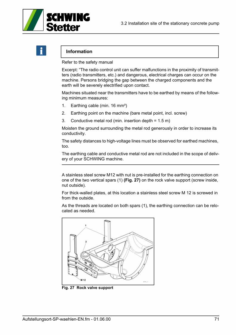
3.2 Installation site of the stationary concrete pump
Information
Refer to the safety manual
Excerpt: “The radio control unit can suffer malfunctions in the proximity of transmit-ters (radio transmitters, etc.) and dangerous, electrical charges can occur on the machine. Persons bridging the gap between the charged components and the earth will be severely electrified upon contact.
Machines situated near the transmitters have to be earthed by means of the follow-ing minimum measures:
1. Earthing cable (min. 16 mm²)
2. Earthing point on the machine (bare metal point, incl. screw)
3. Conductive metal rod (min. insertion depth = 1.5 m)
Moisten the ground surrounding the metal rod generously in order to increase its conductivity.
The safety distances to high-voltage lines must be observed for earthed machines, too.
The earthing cable and conductive metal rod are not included in the scope of deliv-ery of your SCHWING machine.
A stainless steel screw M12 with nut is pre-installed for the earthing connection on one of the two vertical spars (1) (Fig. 27) on the rock valve support (screw inside, nut outside).
For thick-walled plates, at this location a stainless steel screw M 12 is screwed in from the outside.
As the threads are located on both spars (1), the earthing connection can be relo-cated as needed.
Fig. 27 Rock valve support
Aufstellungsort-SP-waehlen-EN.fm - 01.06.00 71

3.2 Installation site of the stationary concrete pump
72 Aufstellungsort-SP-waehlen-EN.fm - 01.06.00
3.3 Electrical connection (optional)
3.3 Electrical connection (optional)
GEFAHR! Danger!
Only authorised personnel may connect, commission and disconnect electri-cally driven machines.
Only authorised personnel may open the switch cabinet.
The operator must initiate the correct connection of the machine.
In Germany, a special feed point is required in accordance with VDE 0100 § 55 (e.g. construction site power supply distributor with ground fault interrupt).
Observe the regulations in the country of use.
3.3.1 Instructions for electricians
3.3.1.1 Standard equipment
• Protection class: IP 54
• Operability during mains voltage fluctuations: ISO class B
• When connecting to the supply line, ensure that a right-hand rotating field is formed
• Protection against radio and television reception disturbances (no disturbances with asynchronous squirrel-cage motors)
• Switching diagrams: see sign in terminal box
• Other protection classes, voltage tolerances, etc. available on request.
Elektrischer-Anschluss-EN.fm - 01.10.00 73
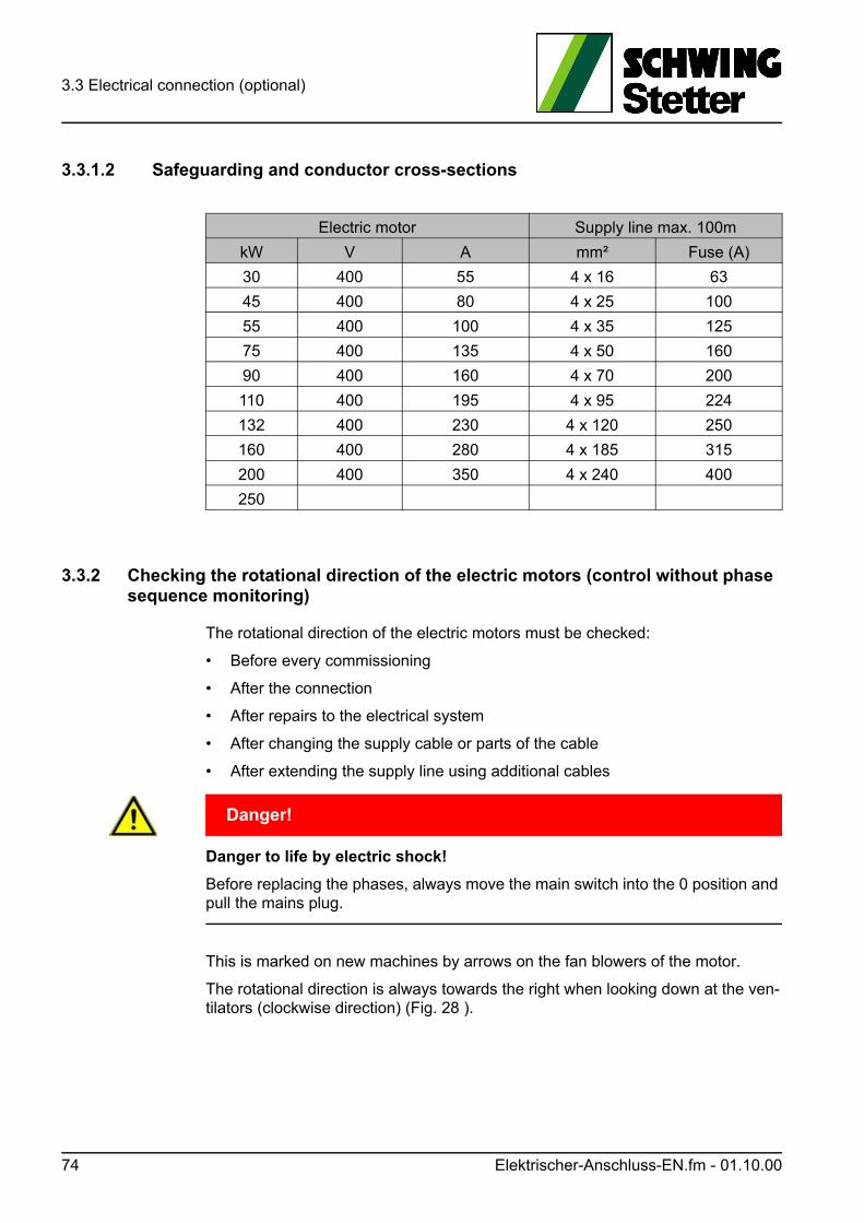
3.3 Electrical connection (optional)
3.3.1.2 Safeguarding and conductor cross-sections
3.3.2 Checking the rotational direction of the electric motors (control without phase sequence monitoring)
The rotational direction of the electric motors must be checked:
• Before every commissioning
• After the connection
• After repairs to the electrical system
• After changing the supply cable or parts of the cable
• After extending the supply line using additional cables
GEFAHR! Danger!
Danger to life by electric shock!
Before replacing the phases, always move the main switch into the 0 position and pull the mains plug.
This is marked on new machines by arrows on the fan blowers of the motor.
The rotational direction is always towards the right when looking down at the ven-tilators (clockwise direction) (Fig. 28 ).
Electric motor Supply line max. 100m
kW V A mm² Fuse (A)
30 400 55 4 x 16 63
45 400 80 4 x 25 100
55 400 100 4 x 35 125
75 400 135 4 x 50 160
90 400 160 4 x 70 200
110 400 195 4 x 95 224
132 400 230 4 x 120 250
160 400 280 4 x 185 315
200 400 350 4 x 240 400
250
74 Elektrischer-Anschluss-EN.fm - 01.10.00
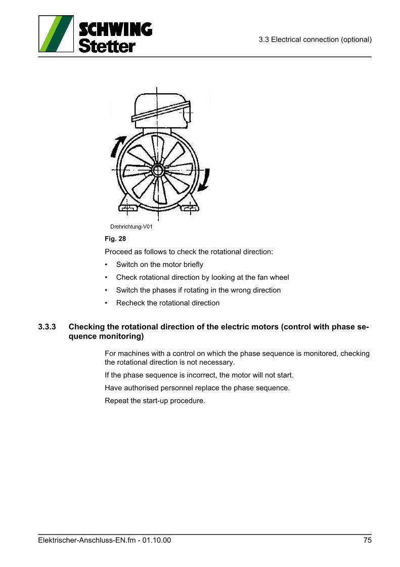
3.3 Electrical connection (optional)
Fig. 28
Proceed as follows to check the rotational direction:
• Switch on the motor briefly
• Check rotational direction by looking at the fan wheel
• Switch the phases if rotating in the wrong direction
• Recheck the rotational direction
3.3.3 Checking the rotational direction of the electric motors (control with phase se-quence monitoring)
For machines with a control on which the phase sequence is monitored, checking the rotational direction is not necessary.
If the phase sequence is incorrect, the motor will not start.
Have authorised personnel replace the phase sequence.
Repeat the start-up procedure.
Elektrischer-Anschluss-EN.fm - 01.10.00 75

3.3 Electrical connection (optional)
76 Elektrischer-Anschluss-EN.fm - 01.10.00

3.4 EMERGENCY-STOP system for SP 1800 / 2800
3.4 EMERGENCY-STOP system for SP 1800 / 2800
Your machine’s EMERGENCY-STOP system is intended to allow you to shut off dangerous machine functions as quickly as possible when other protective meas-ures that have already been taken do not suffice.
Thus, you can prevent a dangerous situation from turning into an accident, mini-mise the severity of an accident or stop a machine malfunction before it causes any damage to the machine.
GEFAHR! Danger!
Risk of accident due to inoperative EMERGENCY-STOP button!
Operating the machine with a defective EMERGENCY STOP system is prohibited and can lead to fatal accidents.
Prior to any working operation, check the function of all EMERGENCY STOP but-tons.
Information
Inform any relevant persons of the positions of the EMERGENCY STOP buttons on your machine so that they can react in emergency situations.
The EMERGENCY STOP buttons built into your machine can be seen in (Fig. 29 EMERGENCY-STOP buttons; similar to illustration)
Fig. 29 EMERGENCY-STOP buttons; similar to illustration
The machine is equipped with EMERGENCY STOP buttons on the machine and remote control (Fig. 30).
Not-Halt-System-SP-1800-2800-EN.fm - 01.02.00 77
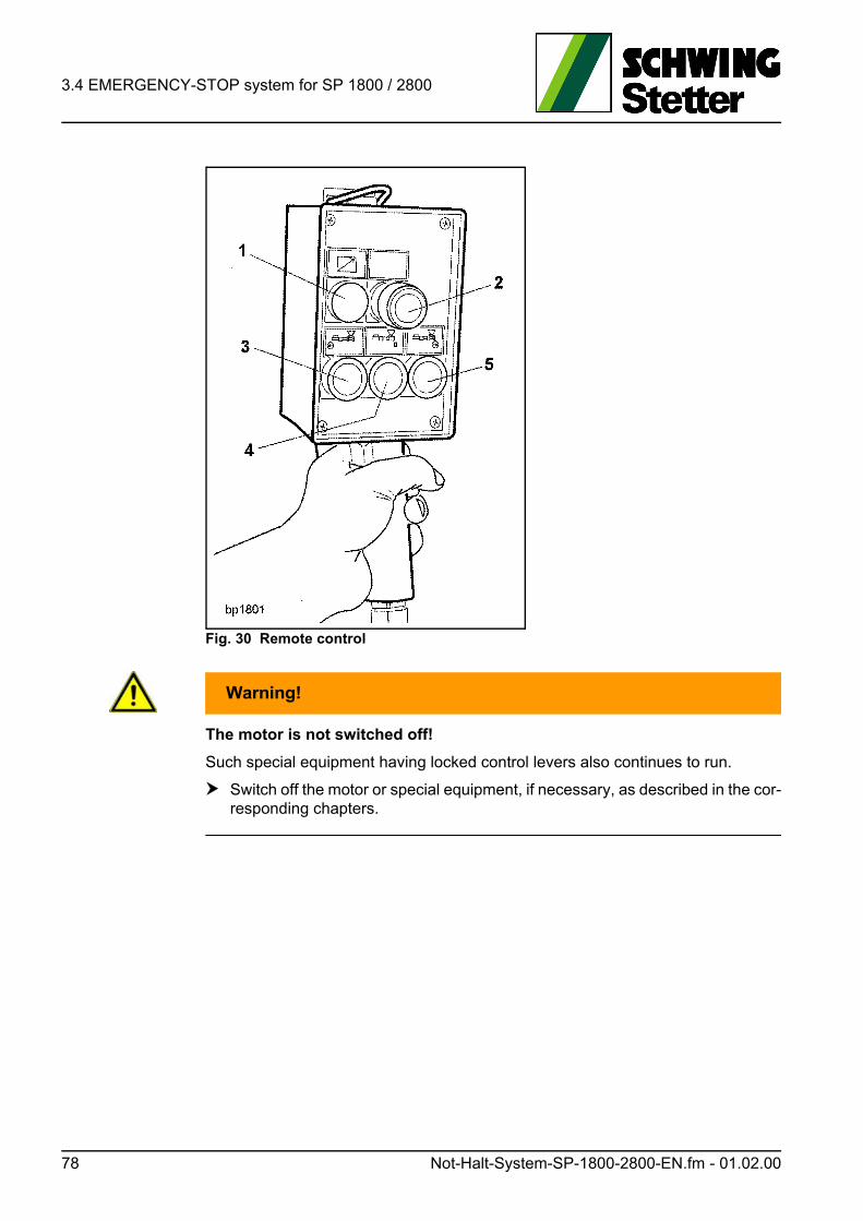
3.4 EMERGENCY-STOP system for SP 1800 / 2800
Fig. 30 Remote control
WARNUNG! Warning!
The motor is not switched off!
Such special equipment having locked control levers also continues to run.
Switch off the motor or special equipment, if necessary, as described in the cor-responding chapters.
78 Not-Halt-System-SP-1800-2800-EN.fm - 01.02.00
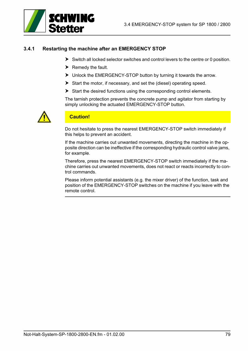
3.4 EMERGENCY-STOP system for SP 1800 / 2800
3.4.1 Restarting the machine after an EMERGENCY STOP
Switch all locked selector switches and control levers to the centre or 0 position.
Remedy the fault.
Unlock the EMERGENCY-STOP button by turning it towards the arrow.
Start the motor, if necessary, and set the (diesel) operating speed.
Start the desired functions using the corresponding control elements.
The tarnish protection prevents the concrete pump and agitator from starting by simply unlocking the actuated EMERGENCY-STOP button.
VORSICHT! Caution!
Do not hesitate to press the nearest EMERGENCY-STOP switch immediately if this helps to prevent an accident.
If the machine carries out unwanted movements, directing the machine in the op-posite direction can be ineffective if the corresponding hydraulic control valve jams, for example.
Therefore, press the nearest EMERGENCY-STOP switch immediately if the ma-chine carries out unwanted movements, does not react or reacts incorrectly to con-trol commands.
Please inform potential assistants (e.g. the mixer driver) of the function, task and position of the EMERGENCY-STOP switches on the machine if you leave with the remote control.
Not-Halt-System-SP-1800-2800-EN.fm - 01.02.00 79

3.4 EMERGENCY-STOP system for SP 1800 / 2800
80 Not-Halt-System-SP-1800-2800-EN.fm - 01.02.00
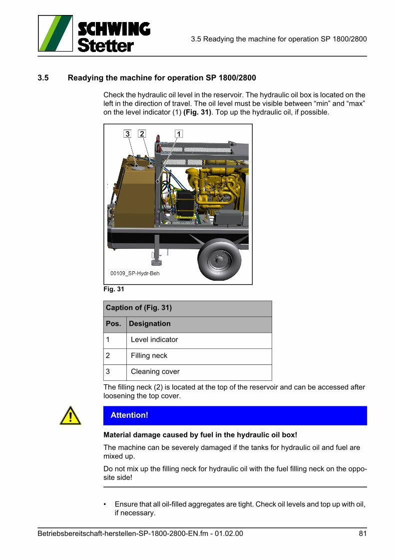
3.5 Readying the machine for operation SP 1800/2800
3.5 Readying the machine for operation SP 1800/2800
Check the hydraulic oil level in the reservoir. The hydraulic oil box is located on the left in the direction of travel. The oil level must be visible between “min” and “max” on the level indicator (1) (Fig. 31). Top up the hydraulic oil, if possible.
Fig. 31
The filling neck (2) is located at the top of the reservoir and can be accessed after loosening the top cover.
ACHTUNG! Attention!
Material damage caused by fuel in the hydraulic oil box!
The machine can be severely damaged if the tanks for hydraulic oil and fuel are mixed up.
Do not mix up the filling neck for hydraulic oil with the fuel filling neck on the oppo-site side!
• Ensure that all oil-filled aggregates are tight. Check oil levels and top up with oil, if necessary.
Caption of (Fig. 31)
Pos. Designation
1 Level indicator
2 Filling neck
3 Cleaning cover
Betriebsbereitschaft-herstellen-SP-1800-2800-EN.fm - 01.02.00 81
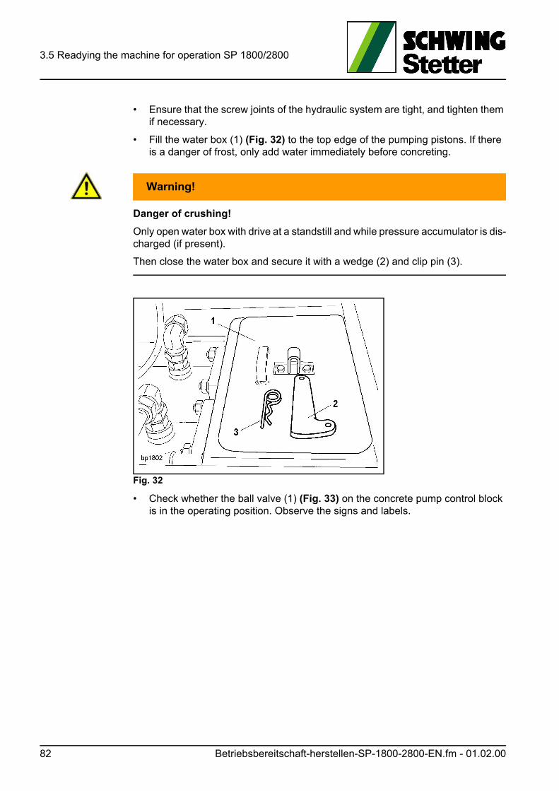
3.5 Readying the machine for operation SP 1800/2800
• Ensure that the screw joints of the hydraulic system are tight, and tighten them if necessary.
• Fill the water box (1) (Fig. 32) to the top edge of the pumping pistons. If there is a danger of frost, only add water immediately before concreting.
WARNUNG! Warning!
Danger of crushing!
Only open water box with drive at a standstill and while pressure accumulator is dis-charged (if present).
Then close the water box and secure it with a wedge (2) and clip pin (3).
Fig. 32
• Check whether the ball valve (1) (Fig. 33) on the concrete pump control block is in the operating position. Observe the signs and labels.
82 Betriebsbereitschaft-herstellen-SP-1800-2800-EN.fm - 01.02.00
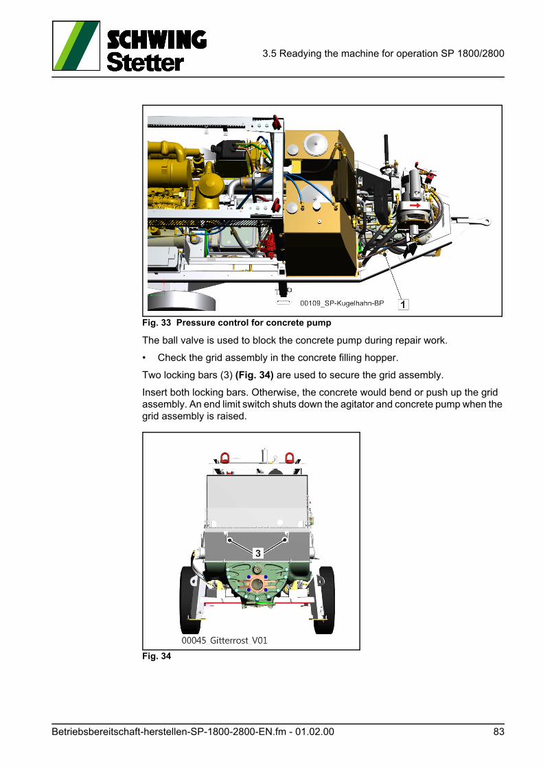
3.5 Readying the machine for operation SP 1800/2800
Fig. 33 Pressure control for concrete pump
The ball valve is used to block the concrete pump during repair work.
• Check the grid assembly in the concrete filling hopper.
Two locking bars (3) (Fig. 34) are used to secure the grid assembly.
Insert both locking bars. Otherwise, the concrete would bend or push up the grid assembly. An end limit switch shuts down the agitator and concrete pump when the grid assembly is raised.
Fig. 34
Betriebsbereitschaft-herstellen-SP-1800-2800-EN.fm - 01.02.00 83
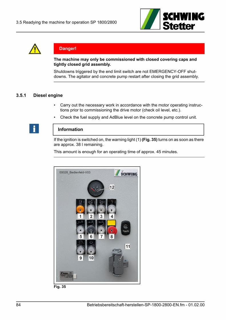
3.5 Readying the machine for operation SP 1800/2800
GEFAHR! Danger!
The machine may only be commissioned with closed covering caps and tightly closed grid assembly.
Shutdowns triggered by the end limit switch are not EMERGENCY-OFF shut-downs. The agitator and concrete pump restart after closing the grid assembly.
3.5.1 Diesel engine
• Carry out the necessary work in accordance with the motor operating instruc-tions prior to commissioning the drive motor (check oil level, etc.).
• Check the fuel supply and AdBlue level on the concrete pump control unit.
Information
If the ignition is switched on, the warning light (1) (Fig. 35) turns on as soon as there are approx. 38 l remaining.
This amount is enough for an operating time of approx. 45 minutes.
Fig. 35
84 Betriebsbereitschaft-herstellen-SP-1800-2800-EN.fm - 01.02.00
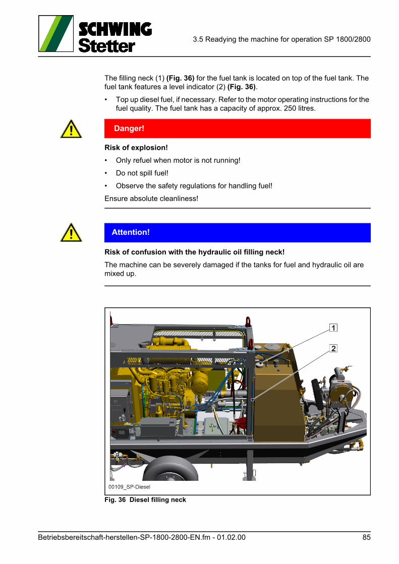
3.5 Readying the machine for operation SP 1800/2800
The filling neck (1) (Fig. 36) for the fuel tank is located on top of the fuel tank. The fuel tank features a level indicator (2) (Fig. 36).
• Top up diesel fuel, if necessary. Refer to the motor operating instructions for the fuel quality. The fuel tank has a capacity of approx. 250 litres.
GEFAHR! Danger!
Risk of explosion!
• Only refuel when motor is not running!
• Do not spill fuel!
• Observe the safety regulations for handling fuel!
Ensure absolute cleanliness!
ACHTUNG! Attention!
Risk of confusion with the hydraulic oil filling neck!
The machine can be severely damaged if the tanks for fuel and hydraulic oil are mixed up.
Fig. 36 Diesel filling neck
Betriebsbereitschaft-herstellen-SP-1800-2800-EN.fm - 01.02.00 85
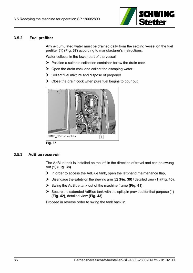
3.5 Readying the machine for operation SP 1800/2800
3.5.2 Fuel prefilter
Any accumulated water must be drained daily from the settling vessel on the fuel prefilter (1) (Fig. 37) according to manufacturer's instructions.
Water collects in the lower part of the vessel.
Position a suitable collection container below the drain cock.
Open the drain cock and collect the escaping water.
Collect fuel mixture and dispose of properly!
Close the drain cock when pure fuel begins to pour out.
Fig. 37
3.5.3 AdBlue reservoir
The AdBlue tank is installed on the left in the direction of travel and can be swung out (1) (Fig. 38).
In order to access the AdBlue tank, open the left-hand maintenance flap,
Disengage the safety on the slewing arm (2) (Fig. 39) / detailed view (1) (Fig. 40),
Swing the AdBlue tank out of the machine frame (Fig. 41),
Secure the extended AdBlue tank with the split pin provided for that purpose (1) (Fig. 42), detailed view (Fig. 43).
Proceed in reverse order to swing the tank back in.
86 Betriebsbereitschaft-herstellen-SP-1800-2800-EN.fm - 01.02.00
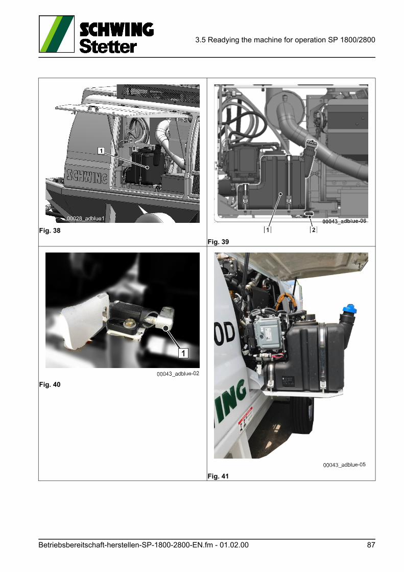
3.5 Readying the machine for operation SP 1800/2800
Fig. 38
Fig. 39
Fig. 40
Fig. 41
Betriebsbereitschaft-herstellen-SP-1800-2800-EN.fm - 01.02.00 87
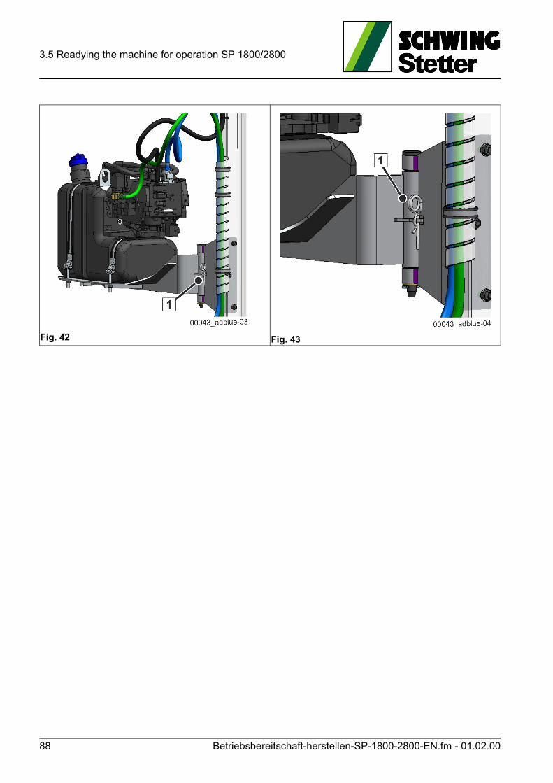
3.5 Readying the machine for operation SP 1800/2800
Fig. 42 Fig. 43
88 Betriebsbereitschaft-herstellen-SP-1800-2800-EN.fm - 01.02.00
3.5 Readying the machine for operation SP 1800/2800
3.5.4 Theoretical operating time
Plan the operating times of the machine carefully before commencing work.
Find out about the average fuel consumption using the consumption values and thus calculate the theoretical operating times, see motor operating instructions!
Information
Engine power failure!
Depending on the engine, observe the required manual or automatic regenerations for the diesel engine.
In pumping operation, the engine speed can be reduced at any time during auto-matic regeneration or the diesel engine will be switched off.
Carry out the manual regeneration in due time according to the motor manufactur-er’s guidelines.
ACHTUNG! Attention!
Machine parts or the entire machine can be destroyed.
Perform the regeneration according to the guidelines.
Betriebsbereitschaft-herstellen-SP-1800-2800-EN.fm - 01.02.00 89
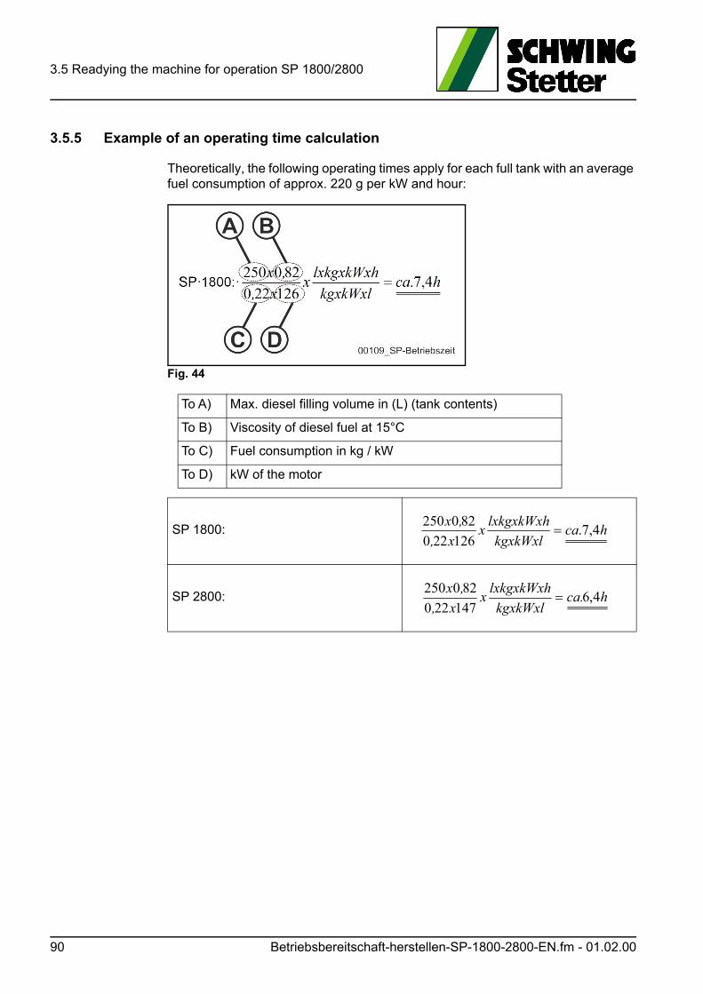
3.5 Readying the machine for operation SP 1800/2800
3.5.5 Example of an operating time calculation
Theoretically, the following operating times apply for each full tank with an average fuel consumption of approx. 220 g per kW and hour:
Fig. 44
To A) Max. diesel filling volume in (L) (tank contents)
To B) Viscosity of diesel fuel at 15°C
To C) Fuel consumption in kg / kW
To D) kW of the motor
SP 1800:
SP 2800: hca.kgxkWxl
lxkgxkWxhx
x,
,x4,6
147220
820250
hcakgxkWxl
lxkgxkWxhx
x,
,x4,7.
126220
820250
90 Betriebsbereitschaft-herstellen-SP-1800-2800-EN.fm - 01.02.00
3.6 Drive circuit SP 1800 / 2800
3.6 Drive circuit SP 1800 / 2800
3.6.1 Starting the diesel engine
VORSICHT! Caution!
Unintentional start-up!
Hydraulic oil pressure is built up automatically!
After starting the drive motor, the hydraulic pumps immediately deliver oil.
Insert the key into the key starter switch (12) (Fig. 45) or (Fig. 46).
Press the key in slightly and turn it clockwise to the first locking position.
The warning lights (1 + 2) light up during a short automatic check (Fig. 45) or (Fig. 46). If no faults are detected, the lights go out after approx. 2 seconds.
If light (1) (Fig. 47) does not go out, check the fuel supply.
Actuate the starter by turning the key further clockwise.
If the motor fails to start up immediately, do not continue trying to start it for more than 10 seconds.
After each start-up procedure, take a one-minute break. Observe cold-start infor-mation in the motor operating instructions.
Once the motor has started, let go of the starter key immediately.
Increase the motor speed slightly using the button (11) (Fig. 45) or (Fig. 46) and let the diesel engine warm up at a moderate speed without a load. Pay attention to any irregularities.
Once the diesel engine has warmed up, check the nominal output (operating speed). To do this, increase the rotational speed with the button (11) and make sure the adjustable maximum speed does not exceed the nominal speed.
If the nominal speed (chap. 2.6) is exceeded, lower the rotational speed imme-diately with the button (10).
• Have the engine timing checked.
If the nominal speed is not reached:
• Have the engine timing checked.
Reduce the engine speed to idle until the concrete pump is placed into opera-tion.
Antriebsschaltung-SP-1800-2800-EN.fm - 01.06.00 91

3.6 Drive circuit SP 1800 / 2800
Fig. 45 Control panel with regeneration
Fig. 46 Control panel with TSC
92 Antriebsschaltung-SP-1800-2800-EN.fm - 01.06.00
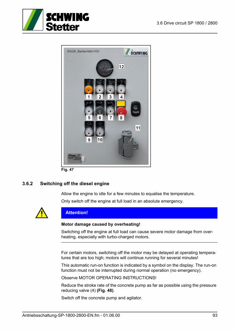
3.6 Drive circuit SP 1800 / 2800
Fig. 47
3.6.2 Switching off the diesel engine
Allow the engine to idle for a few minutes to equalise the temperature.
Only switch off the engine at full load in an absolute emergency.
ACHTUNG! Attention!
Motor damage caused by overheating!
Switching off the engine at full load can cause severe motor damage from over-heating, especially with turbo-charged motors.
For certain motors, switching off the motor may be delayed at operating tempera-tures that are too high; motors will continue running for several minutes!
This automatic run-on function is indicated by a symbol on the display. The run-on function must not be interrupted during normal operation (no emergency).
Observe MOTOR OPERATING INSTRUCTIONS!
Reduce the stroke rate of the concrete pump as far as possible using the pressure reducing valve (4) (Fig. 48).
Switch off the concrete pump and agitator.
Antriebsschaltung-SP-1800-2800-EN.fm - 01.06.00 93
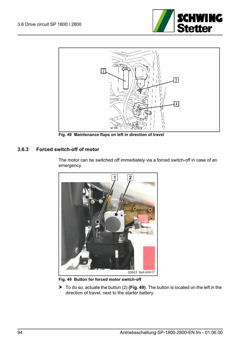
3.6 Drive circuit SP 1800 / 2800
Fig. 48 Maintenance flaps on left in direction of travel
3.6.3 Forced switch-off of motor
The motor can be switched off immediately via a forced switch-off in case of an emergency.
Fig. 49 Button for forced motor switch-off
To do so, actuate the button (2) (Fig. 49). The button is located on the left in the direction of travel, next to the starter battery.
94 Antriebsschaltung-SP-1800-2800-EN.fm - 01.06.00
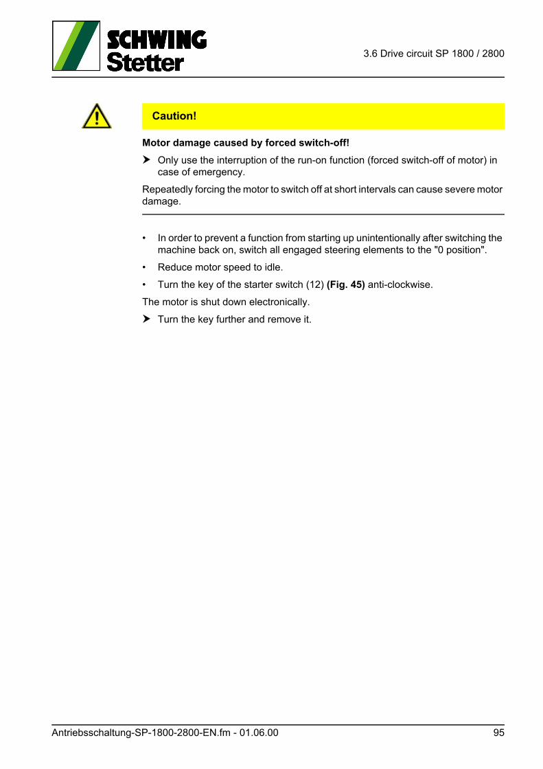
3.6 Drive circuit SP 1800 / 2800
VORSICHT! Caution!
Motor damage caused by forced switch-off!
Only use the interruption of the run-on function (forced switch-off of motor) in case of emergency.
Repeatedly forcing the motor to switch off at short intervals can cause severe motor damage.
• In order to prevent a function from starting up unintentionally after switching the machine back on, switch all engaged steering elements to the "0 position".
• Reduce motor speed to idle.
• Turn the key of the starter switch (12) (Fig. 45) anti-clockwise.
The motor is shut down electronically.
Turn the key further and remove it.
Antriebsschaltung-SP-1800-2800-EN.fm - 01.06.00 95

3.6 Drive circuit SP 1800 / 2800
96 Antriebsschaltung-SP-1800-2800-EN.fm - 01.06.00
3.7 Setting up the machine
3.7 Setting up the machine
The installation site must be set up so that the transport vehicles can reach the con-crete filling hopper without any problems and the machine is accessible for main-tenance and cleaning purposes.
• Inquire about the permissible ground pressure at the jobsite. Refer to the tech-nical specifications for the max. single outrigger static load.Deviations are possible due to different equipment versions.
• If necessary, use load-distributing underlay supports beneath the supporting dishes.
GEFAHR! Danger!
Loss of stability!
The machine must not be installed if its maximum ground pressure exceeds the permissible value.
If necessary, the support surface must be extended using suitable means until the permissible ground pressure is reached.
Always insert socket pins and split pins to secure after supporting.
Unburden hydraulic!
Depending on the machine’s length of stay, we recommend using our support pads (item no.: 1095646) or creating a suitable concrete surface.
ACHTUNG! Attention!
Extend hydraulic supports evenly, insert socket pins and split pins, and un-burden hydraulics.
Do not drive a cylinder to the limit stop before the next one has been driven. The frame and outrigger were put under unnecessary strain.
If load-distributing underlay supports are used, they must be suitable and undam-aged, as well as free of ice, oil, grease etc.
Maschine-aufstellen-EN.fm - 01.03.00 97
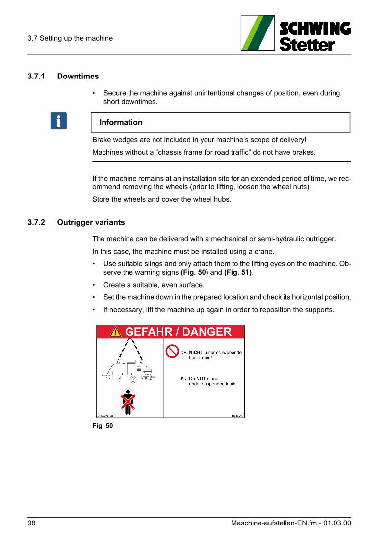
3.7 Setting up the machine
3.7.1 Downtimes
• Secure the machine against unintentional changes of position, even during short downtimes.
Information
Brake wedges are not included in your machine’s scope of delivery!
Machines without a “chassis frame for road traffic” do not have brakes.
If the machine remains at an installation site for an extended period of time, we rec-ommend removing the wheels (prior to lifting, loosen the wheel nuts).
Store the wheels and cover the wheel hubs.
3.7.2 Outrigger variants
The machine can be delivered with a mechanical or semi-hydraulic outrigger.
In this case, the machine must be installed using a crane.
• Use suitable slings and only attach them to the lifting eyes on the machine. Ob-serve the warning signs (Fig. 50) and (Fig. 51).
• Create a suitable, even surface.
• Set the machine down in the prepared location and check its horizontal position.
• If necessary, lift the machine up again in order to reposition the supports.
Fig. 50
98 Maschine-aufstellen-EN.fm - 01.03.00
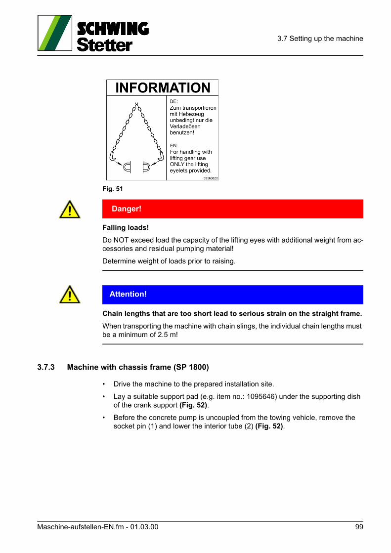
3.7 Setting up the machine
Fig. 51
GEFAHR! Danger!
Falling loads!
Do NOT exceed load the capacity of the lifting eyes with additional weight from ac-cessories and residual pumping material!
Determine weight of loads prior to raising.
ACHTUNG! Attention!
Chain lengths that are too short lead to serious strain on the straight frame.
When transporting the machine with chain slings, the individual chain lengths must be a minimum of 2.5 m!
3.7.3 Machine with chassis frame (SP 1800)
• Drive the machine to the prepared installation site.
• Lay a suitable support pad (e.g. item no.: 1095646) under the supporting dish of the crank support (Fig. 52).
• Before the concrete pump is uncoupled from the towing vehicle, remove the socket pin (1) and lower the interior tube (2) (Fig. 52).
Maschine-aufstellen-EN.fm - 01.03.00 99
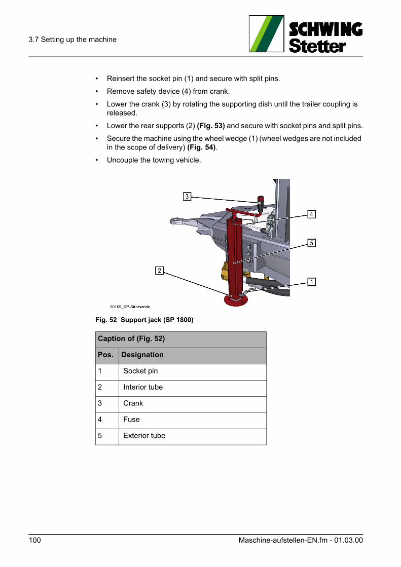
3.7 Setting up the machine
• Reinsert the socket pin (1) and secure with split pins.
• Remove safety device (4) from crank.
• Lower the crank (3) by rotating the supporting dish until the trailer coupling is released.
• Lower the rear supports (2) (Fig. 53) and secure with socket pins and split pins.
• Secure the machine using the wheel wedge (1) (wheel wedges are not included in the scope of delivery) (Fig. 54).
• Uncouple the towing vehicle.
Fig. 52 Support jack (SP 1800)
Caption of (Fig. 52)
Pos. Designation
1 Socket pin
2 Interior tube
3 Crank
4 Fuse
5 Exterior tube
100 Maschine-aufstellen-EN.fm - 01.03.00
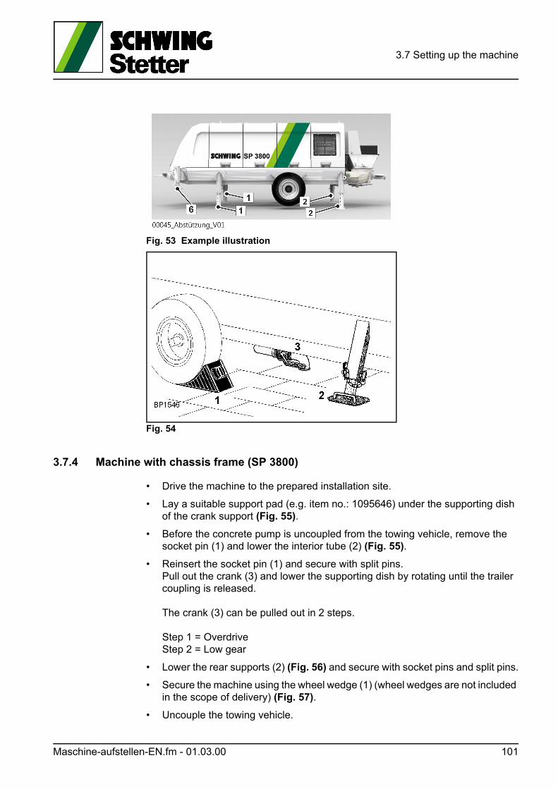
3.7 Setting up the machine
Fig. 53 Example illustration
Fig. 54
3.7.4 Machine with chassis frame (SP 3800)
• Drive the machine to the prepared installation site.
• Lay a suitable support pad (e.g. item no.: 1095646) under the supporting dish of the crank support (Fig. 55).
• Before the concrete pump is uncoupled from the towing vehicle, remove the socket pin (1) and lower the interior tube (2) (Fig. 55).
• Reinsert the socket pin (1) and secure with split pins.Pull out the crank (3) and lower the supporting dish by rotating until the trailer coupling is released.
The crank (3) can be pulled out in 2 steps.
Step 1 = OverdriveStep 2 = Low gear
• Lower the rear supports (2) (Fig. 56) and secure with socket pins and split pins.
• Secure the machine using the wheel wedge (1) (wheel wedges are not included in the scope of delivery) (Fig. 57).
• Uncouple the towing vehicle.
Maschine-aufstellen-EN.fm - 01.03.00 101
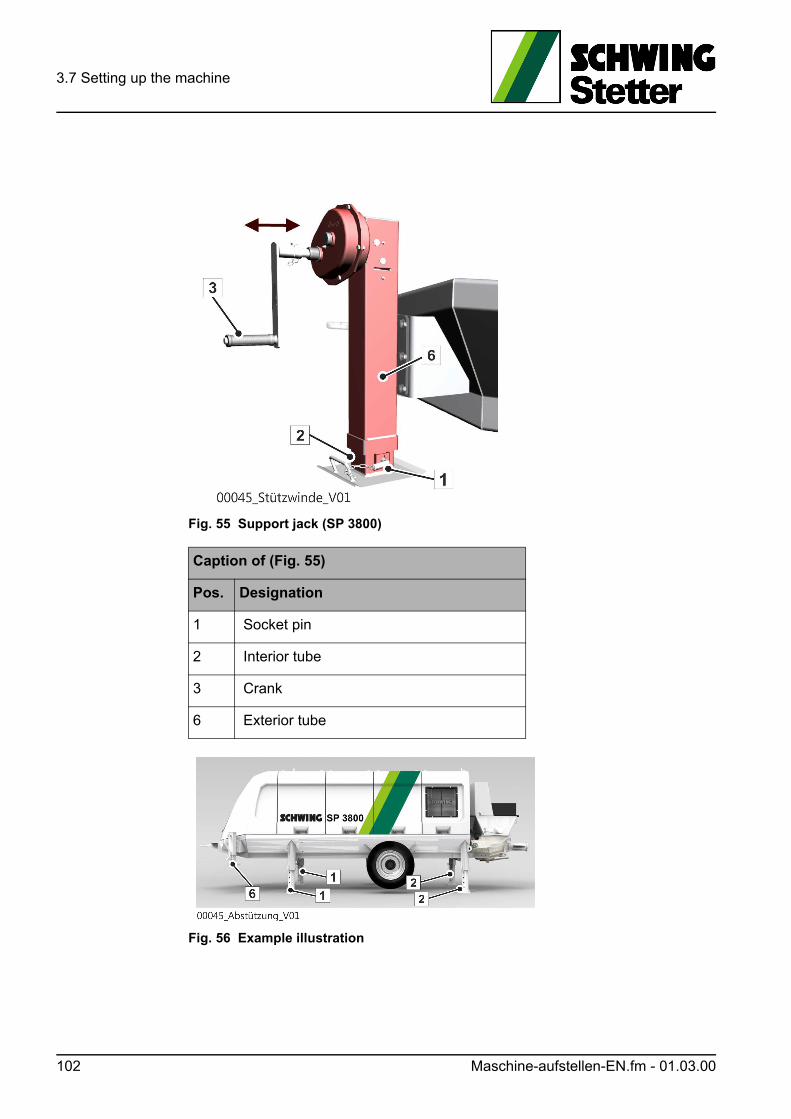
3.7 Setting up the machine
Fig. 55 Support jack (SP 3800)
Fig. 56 Example illustration
Caption of (Fig. 55)
Pos. Designation
1 Socket pin
2 Interior tube
3 Crank
6 Exterior tube
102 Maschine-aufstellen-EN.fm - 01.03.00
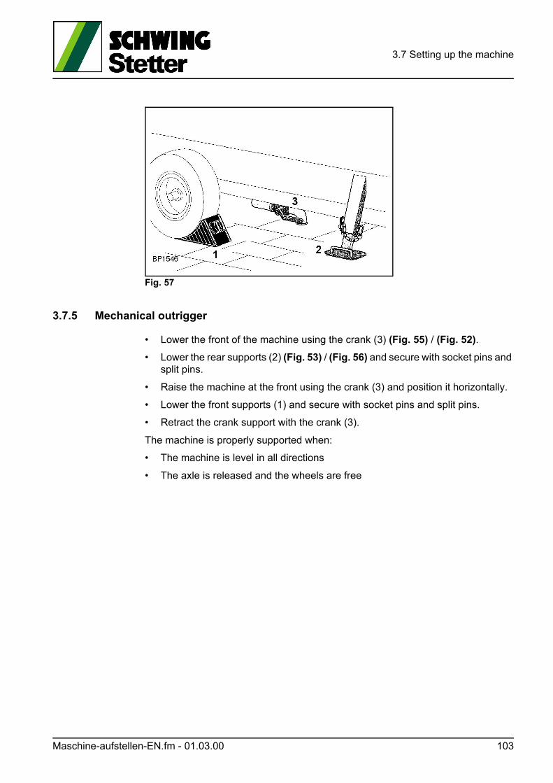
3.7 Setting up the machine
Fig. 57
3.7.5 Mechanical outrigger
• Lower the front of the machine using the crank (3) (Fig. 55) / (Fig. 52).
• Lower the rear supports (2) (Fig. 53) / (Fig. 56) and secure with socket pins and split pins.
• Raise the machine at the front using the crank (3) and position it horizontally.
• Lower the front supports (1) and secure with socket pins and split pins.
• Retract the crank support with the crank (3).
The machine is properly supported when:
• The machine is level in all directions
• The axle is released and the wheels are free
Maschine-aufstellen-EN.fm - 01.03.00 103
3.7 Setting up the machine
3.7.6 Semi-hydraulic outrigger (optional)
For the semi-hydraulic outrigger, the oil flow from the agitator pump is directed into the control blocks of the outrigger.
• Lower the front of the machine using the crank (3) (Fig. 52) / (Fig. 55).
• Start the motor.
• Extend the front and rear hydraulic supports (1+2) on both sides of the machine using the control levers.Extend the hydraulic supports evenly until the machine is horizontal in all direc-tions.The control levers are spring-centred and return to the central position once they have been released.
• Retract the crank support with the crank (3).
The machine is properly supported when:
• The machine is level in all directions
• The axle is released and the wheels are free
GEFAHR! Danger!
Loss of stability
Always insert socket pins and split pins to secure after supporting.
Unburden hydraulic!
GEFAHR! Danger!
Danger of crushing!
Do NOT remain in the danger area during actuation of the support legs!
104 Maschine-aufstellen-EN.fm - 01.03.00
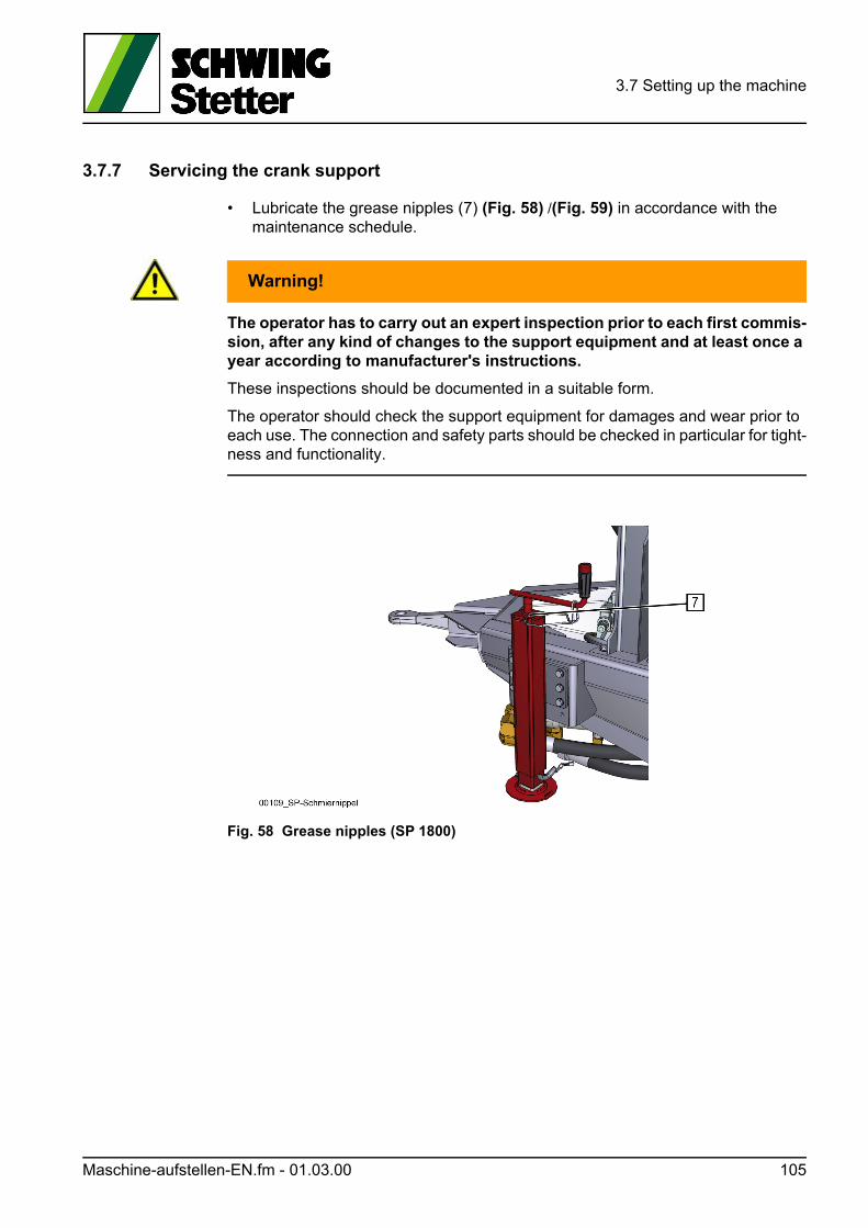
3.7 Setting up the machine
3.7.7 Servicing the crank support
• Lubricate the grease nipples (7) (Fig. 58) /(Fig. 59) in accordance with the maintenance schedule.
WARNUNG! Warning!
The operator has to carry out an expert inspection prior to each first commis-sion, after any kind of changes to the support equipment and at least once a year according to manufacturer's instructions.
These inspections should be documented in a suitable form.
The operator should check the support equipment for damages and wear prior to each use. The connection and safety parts should be checked in particular for tight-ness and functionality.
Fig. 58 Grease nipples (SP 1800)
Maschine-aufstellen-EN.fm - 01.03.00 105
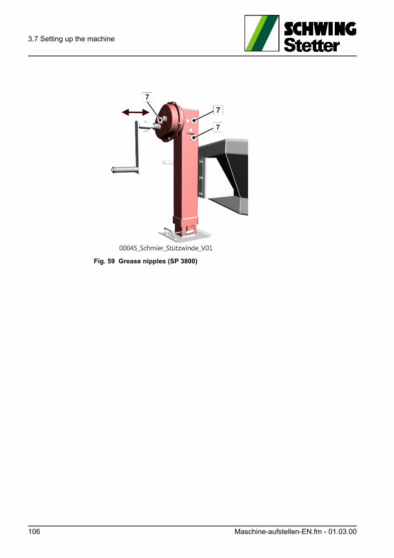
3.7 Setting up the machine
Fig. 59 Grease nipples (SP 3800)
106 Maschine-aufstellen-EN.fm - 01.03.00
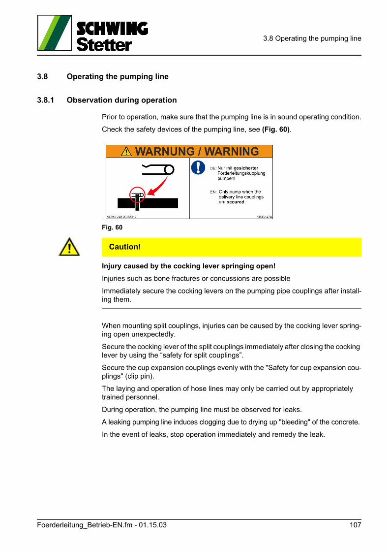
3.8 Operating the pumping line
3.8 Operating the pumping line
3.8.1 Observation during operation
Prior to operation, make sure that the pumping line is in sound operating condition.
Check the safety devices of the pumping line, see (Fig. 60).
Fig. 60
VORSICHT! Caution!
Injury caused by the cocking lever springing open!
Injuries such as bone fractures or concussions are possible
Immediately secure the cocking levers on the pumping pipe couplings after install-ing them.
When mounting split couplings, injuries can be caused by the cocking lever spring-ing open unexpectedly.
Secure the cocking lever of the split couplings immediately after closing the cocking lever by using the “safety for split couplings”.
Secure the cup expansion couplings evenly with the "Safety for cup expansion cou-plings" (clip pin).
The laying and operation of hose lines may only be carried out by appropriately trained personnel.
During operation, the pumping line must be observed for leaks.
A leaking pumping line induces clogging due to drying up "bleeding" of the concrete.
In the event of leaks, stop operation immediately and remedy the leak.
Foerderleitung_Betrieb-EN.fm - 01.15.03 107
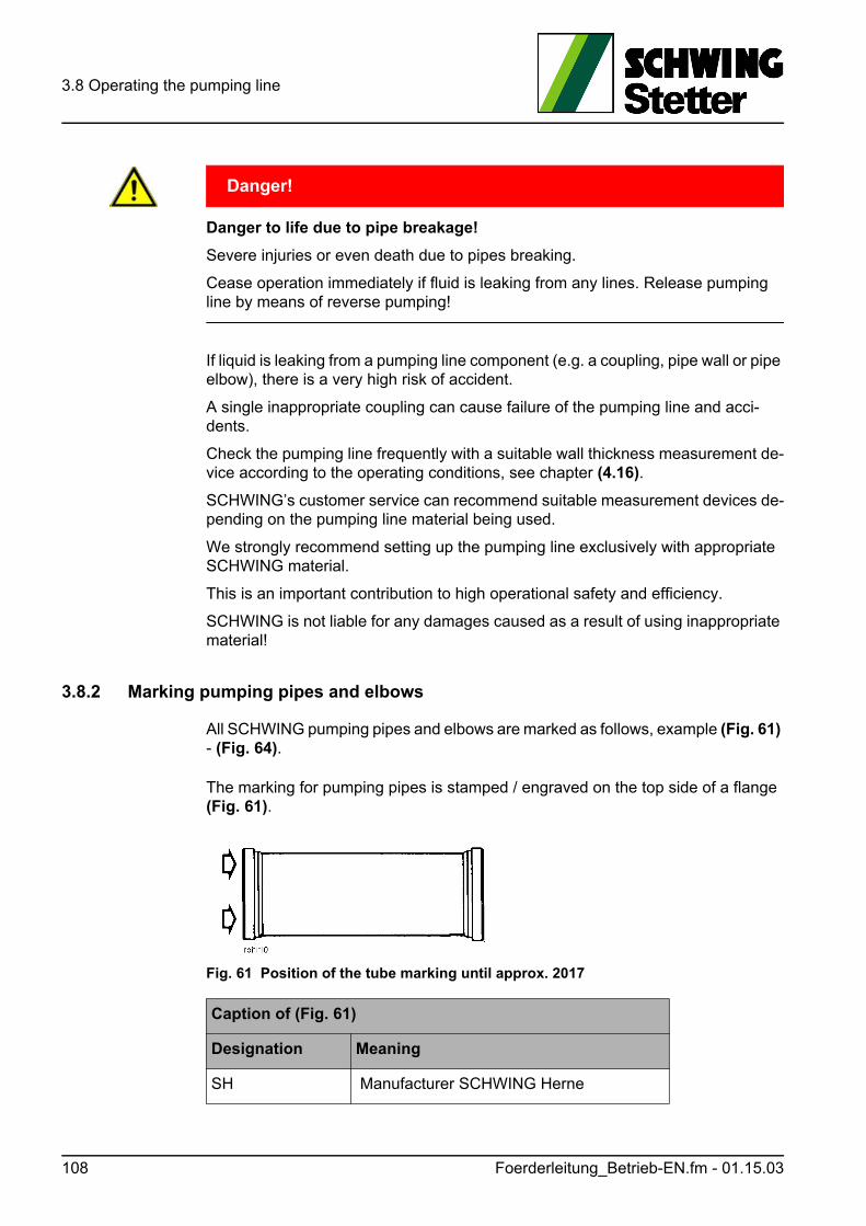
3.8 Operating the pumping line
GEFAHR! Danger!
Danger to life due to pipe breakage!
Severe injuries or even death due to pipes breaking.
Cease operation immediately if fluid is leaking from any lines. Release pumping line by means of reverse pumping!
If liquid is leaking from a pumping line component (e.g. a coupling, pipe wall or pipe elbow), there is a very high risk of accident.
A single inappropriate coupling can cause failure of the pumping line and acci-dents.
Check the pumping line frequently with a suitable wall thickness measurement de-vice according to the operating conditions, see chapter (4.16).
SCHWING’s customer service can recommend suitable measurement devices de-pending on the pumping line material being used.
We strongly recommend setting up the pumping line exclusively with appropriate SCHWING material.
This is an important contribution to high operational safety and efficiency.
SCHWING is not liable for any damages caused as a result of using inappropriate material!
3.8.2 Marking pumping pipes and elbows
All SCHWING pumping pipes and elbows are marked as follows, example (Fig. 61) - (Fig. 64).
The marking for pumping pipes is stamped / engraved on the top side of a flange (Fig. 61).
Fig. 61 Position of the tube marking until approx. 2017
Caption of (Fig. 61)
Designation Meaning
SH Manufacturer SCHWING Herne
108 Foerderleitung_Betrieb-EN.fm - 01.15.03
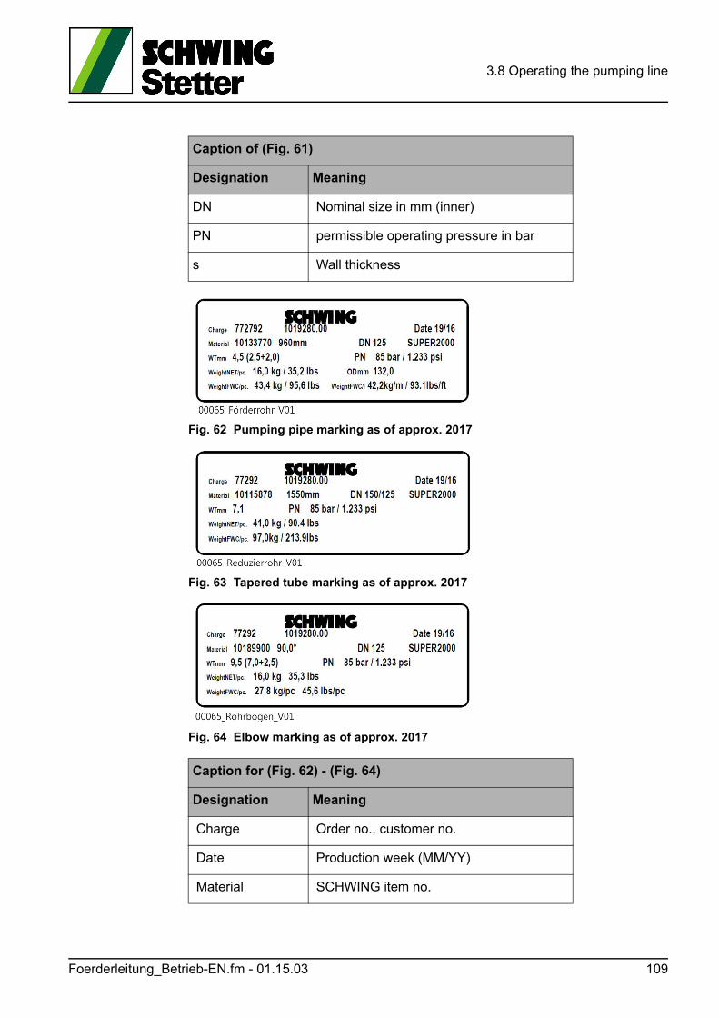
3.8 Operating the pumping line
Fig. 62 Pumping pipe marking as of approx. 2017
Fig. 63 Tapered tube marking as of approx. 2017
Fig. 64 Elbow marking as of approx. 2017
DN Nominal size in mm (inner)
PN permissible operating pressure in bar
s Wall thickness
Caption for (Fig. 62) - (Fig. 64)
Designation Meaning
Charge Order no., customer no.
Date Production week (MM/YY)
Material SCHWING item no.
Caption of (Fig. 61)
Designation Meaning
Foerderleitung_Betrieb-EN.fm - 01.15.03 109
3.8 Operating the pumping line
3.8.3 Marking the pumping line on the placing boom
A distinctive type plate is located on the placing boom for the placing boom pump-ing line (Fig. 65). The nominal sizes (DN) specified on this type plate are the max-imum allowable.
The nominal sizes and the wall thicknesses of the pumping line and the gross den-sity of the pumped concrete must not exceed the specified limits.
The maximum operating pressures (PN) specified on the components and type plates are the maximum permissible operating pressures for components in new condition. If the minimum wall thickness is not met, then replace the tubes and el-bows.
With truck-mounted concrete pumps, the concrete pressure for rod and piston-side pressure is also indicated on the type plate of the concrete pump (Fig. 66).
If no value is given for the rod side, it refers to a piston-sided pressurised concrete pump.
This concrete pump may not be interchanged!
-- Dimensions mm/degree
DN Nominal size in mm (inner diameter)
SUPER 1000 SCHWING quality label
WTmm Total thickness (inside wall + outside wall)
PN permissible operating pressure in bar
WeightNET/pc. Net unit weight
OD Outer diameter mm
Weight-FWC/pc.Tube, elbow and tapered tube weight per unit, filled with concrete
WeightFWC/lTube weight per metre without flange, filled with concrete
Caption for (Fig. 62) - (Fig. 64)
Designation Meaning
110 Foerderleitung_Betrieb-EN.fm - 01.15.03
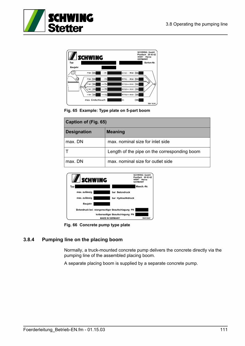
3.8 Operating the pumping line
Fig. 65 Example: Type plate on 5-part boom
Fig. 66 Concrete pump type plate
3.8.4 Pumping line on the placing boom
Normally, a truck-mounted concrete pump delivers the concrete directly via the pumping line of the assembled placing boom.
A separate placing boom is supplied by a separate concrete pump.
Caption of (Fig. 65)
Designation Meaning
max. DN max. nominal size for inlet side
T Length of the pipe on the corresponding boom
max. DN max. nominal size for outlet side
Foerderleitung_Betrieb-EN.fm - 01.15.03 111
3.8 Operating the pumping line
GEFAHR! Danger!
Loss of stability due to excessively heavy pumping lines on the placing boom!
The machine can topple over and cause severe or even fatal injuries as a result.
The concrete pumping line installed on the placing boom is an integral part of the machine and must not be changed.
In an extreme situation, the increased breakdown torque may cause the machine to topple over.
Pumping pipes with an excessive tare weight (thicker walls) and pumping pipes with larger diameters can overload the placing boom.
Unsuitable pumping lines cause damage (especially broken tube holders, cracks in boom profiles, etc.).
Due to changes to the pumping line, other safety-relevant adjustments of the ma-chine may be mandatory.
After major changes that are not carried out by SCHWING, placing booms must be inspected by an expert before being recommissioned, see (3.8.5).
3.8.5 Disclaimer
Independent modifications to the machine and using spare parts and accessories that have not been approved by SCHWING fall under the definition of “improper use”.
This also applies to the use of individual parts, such as: Tubes, couplings, elbows, etc.
We would like to draw attention once again to the fact that SCHWING is not liable for damages caused by improper or negligent operation, maintenance and repair or improper use.
This also applies to expansions and conversions, as well as other changes to the machine not approved by SCHWING.
For mounting and operation of separate pumping lines (tubes or hoses), the oper-ator bears sole responsibility!
112 Foerderleitung_Betrieb-EN.fm - 01.15.03
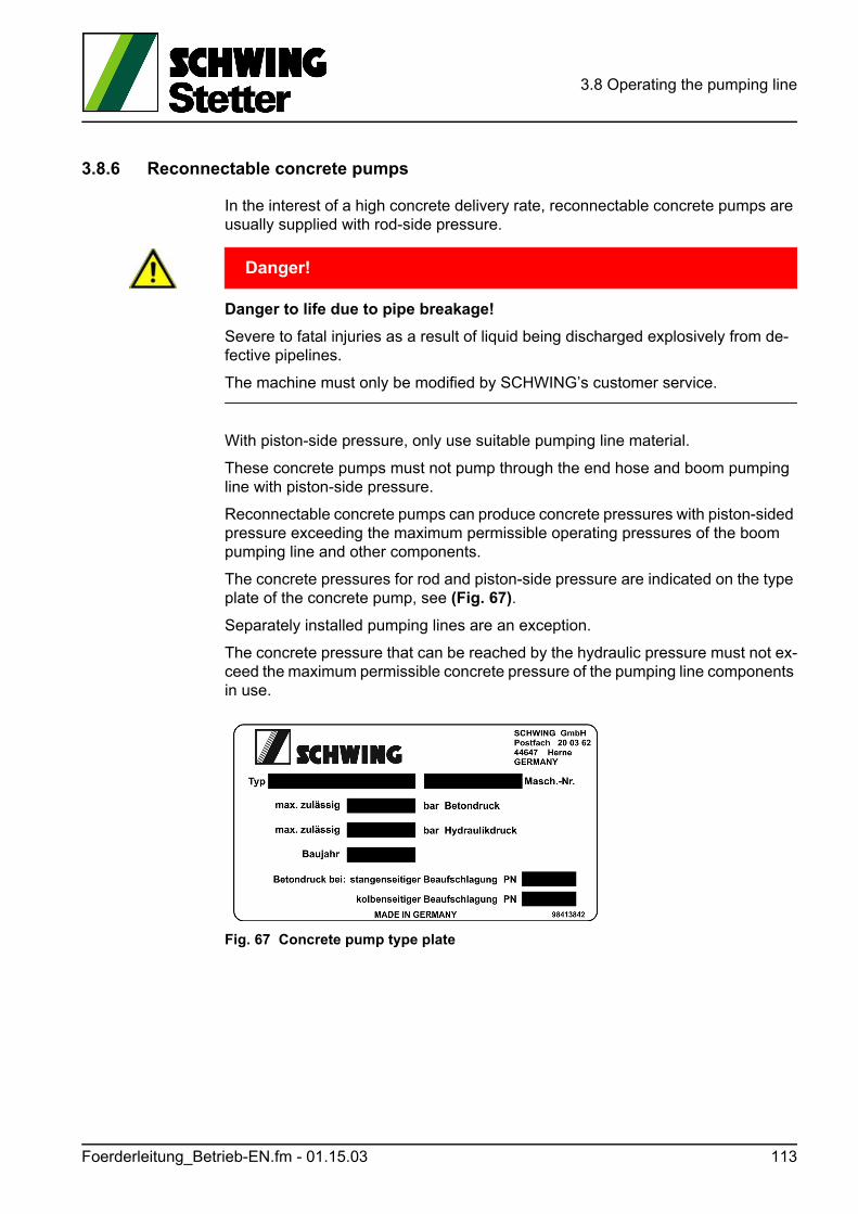
3.8 Operating the pumping line
3.8.6 Reconnectable concrete pumps
In the interest of a high concrete delivery rate, reconnectable concrete pumps are usually supplied with rod-side pressure.
GEFAHR! Danger!
Danger to life due to pipe breakage!
Severe to fatal injuries as a result of liquid being discharged explosively from de-fective pipelines.
The machine must only be modified by SCHWING’s customer service.
With piston-side pressure, only use suitable pumping line material.
These concrete pumps must not pump through the end hose and boom pumping line with piston-side pressure.
Reconnectable concrete pumps can produce concrete pressures with piston-sided pressure exceeding the maximum permissible operating pressures of the boom pumping line and other components.
The concrete pressures for rod and piston-side pressure are indicated on the type plate of the concrete pump, see (Fig. 67).
Separately installed pumping lines are an exception.
The concrete pressure that can be reached by the hydraulic pressure must not ex-ceed the maximum permissible concrete pressure of the pumping line components in use.
Fig. 67 Concrete pump type plate
Foerderleitung_Betrieb-EN.fm - 01.15.03 113
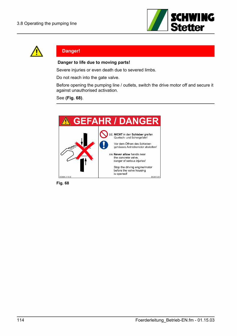
3.8 Operating the pumping line
GEFAHR! Danger!
Danger to life due to moving parts!
Severe injuries or even death due to severed limbs.
Do not reach into the gate valve.
Before opening the pumping line / outlets, switch the drive motor off and secure it against unauthorised activation.
See (Fig. 68).
Fig. 68
114 Foerderleitung_Betrieb-EN.fm - 01.15.03
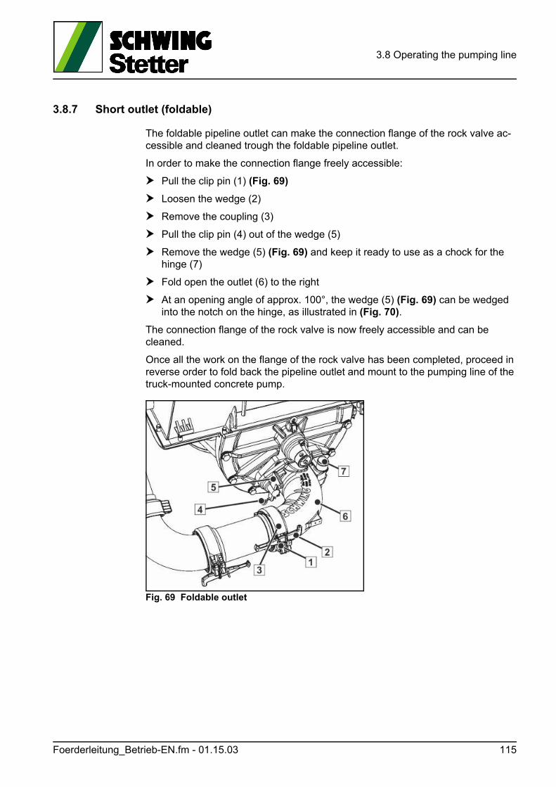
3.8 Operating the pumping line
3.8.7 Short outlet (foldable)
The foldable pipeline outlet can make the connection flange of the rock valve ac-cessible and cleaned trough the foldable pipeline outlet.
In order to make the connection flange freely accessible:
Pull the clip pin (1) (Fig. 69)
Loosen the wedge (2)
Remove the coupling (3)
Pull the clip pin (4) out of the wedge (5)
Remove the wedge (5) (Fig. 69) and keep it ready to use as a chock for the hinge (7)
Fold open the outlet (6) to the right
At an opening angle of approx. 100°, the wedge (5) (Fig. 69) can be wedged into the notch on the hinge, as illustrated in (Fig. 70).
The connection flange of the rock valve is now freely accessible and can be cleaned.
Once all the work on the flange of the rock valve has been completed, proceed in reverse order to fold back the pipeline outlet and mount to the pumping line of the truck-mounted concrete pump.
Fig. 69 Foldable outlet
Foerderleitung_Betrieb-EN.fm - 01.15.03 115
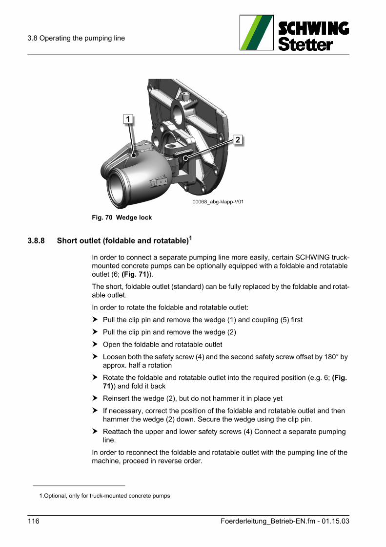
3.8 Operating the pumping line
Fig. 70 Wedge lock
3.8.8 Short outlet (foldable and rotatable)1
In order to connect a separate pumping line more easily, certain SCHWING truck-mounted concrete pumps can be optionally equipped with a foldable and rotatable outlet (6; (Fig. 71)).
The short, foldable outlet (standard) can be fully replaced by the foldable and rotat-able outlet.
In order to rotate the foldable and rotatable outlet:
Pull the clip pin and remove the wedge (1) and coupling (5) first
Pull the clip pin and remove the wedge (2)
Open the foldable and rotatable outlet
Loosen both the safety screw (4) and the second safety screw offset by 180° by approx. half a rotation
Rotate the foldable and rotatable outlet into the required position (e.g. 6; (Fig. 71)) and fold it back
Reinsert the wedge (2), but do not hammer it in place yet
If necessary, correct the position of the foldable and rotatable outlet and then hammer the wedge (2) down. Secure the wedge using the clip pin.
Reattach the upper and lower safety screws (4) Connect a separate pumping line.
In order to reconnect the foldable and rotatable outlet with the pumping line of the machine, proceed in reverse order.
1.Optional, only for truck-mounted concrete pumps
116 Foerderleitung_Betrieb-EN.fm - 01.15.03
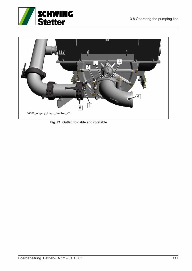
3.8 Operating the pumping line
Fig. 71 Outlet, foldable and rotatable
Foerderleitung_Betrieb-EN.fm - 01.15.03 117
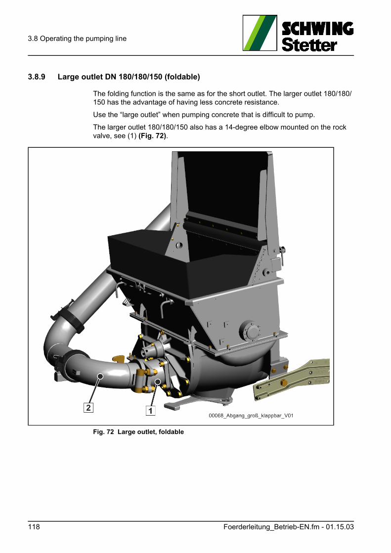
3.8 Operating the pumping line
3.8.9 Large outlet DN 180/180/150 (foldable)
The folding function is the same as for the short outlet. The larger outlet 180/180/150 has the advantage of having less concrete resistance.
Use the “large outlet” when pumping concrete that is difficult to pump.
The larger outlet 180/180/150 also has a 14-degree elbow mounted on the rock valve, see (1) (Fig. 72).
Fig. 72 Large outlet, foldable
118 Foerderleitung_Betrieb-EN.fm - 01.15.03
3.8 Operating the pumping line
3.8.10 Servicing the foldable and rotatable outlet
Once a week, squeeze some lubricating grease into the grease nipple (3) (Fig. 71) and into the second nipple offset by 180°.
Actuate the grease gun until the grease visibly emerges.
Lubricate the seal of the split coupling with lubricating grease prior to mounting.
Clean used seals and check them for damage prior to mounting.
3.8.11 Separate pumping line
The use of a stationary concrete pump must always be planned carefully.
In addition to the selection of the right pump, the selection and installation of the pumping line is of great significance.
Both must be done with great care and expertise.
SCHWING offers an extensive range of pumping lines and accessories.
Should you have any questions regarding the pumping line, please contact SCHWING Customer Service.
When selecting the pumping lines, observe the maximum possible concrete pres-sure of the concrete pump, depending on the:
• Drive power of the concrete pump
• installed pump kit
• Application of the differential cylinder
Certain stationary concrete pumps can, for example, generate a concrete pressure of over 200 bar, see type plate.
These maximum values are rarely achieved during the normal operation.
However, given that, in the event of clogging, the complete pipeline between the concrete pump and the clog is under maximum pressure, the entire pumping line must be able to tolerate these values.
Foerderleitung_Betrieb-EN.fm - 01.15.03 119
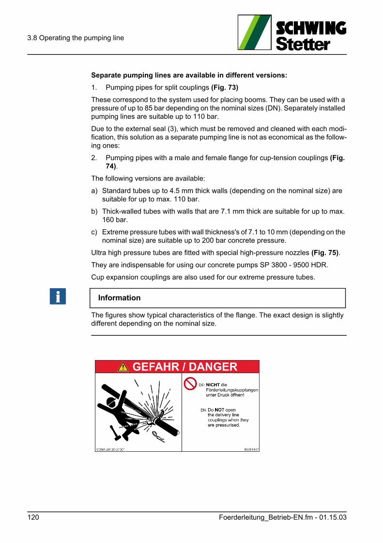
3.8 Operating the pumping line
Separate pumping lines are available in different versions:
1. Pumping pipes for split couplings (Fig. 73)
These correspond to the system used for placing booms. They can be used with a pressure of up to 85 bar depending on the nominal sizes (DN). Separately installed pumping lines are suitable up to 110 bar.
Due to the external seal (3), which must be removed and cleaned with each modi-fication, this solution as a separate pumping line is not as economical as the follow-ing ones:
2. Pumping pipes with a male and female flange for cup-tension couplings (Fig. 74).
The following versions are available:
a) Standard tubes up to 4.5 mm thick walls (depending on the nominal size) are suitable for up to max. 110 bar.
b) Thick-walled tubes with walls that are 7.1 mm thick are suitable for up to max. 160 bar.
c) Extreme pressure tubes with wall thickness's of 7.1 to 10 mm (depending on the nominal size) are suitable up to 200 bar concrete pressure.
Ultra high pressure tubes are fitted with special high-pressure nozzles (Fig. 75).
They are indispensable for using our concrete pumps SP 3800 - 9500 HDR.
Cup expansion couplings are also used for our extreme pressure tubes.
Information
The figures show typical characteristics of the flange. The exact design is slightly different depending on the nominal size.
120 Foerderleitung_Betrieb-EN.fm - 01.15.03
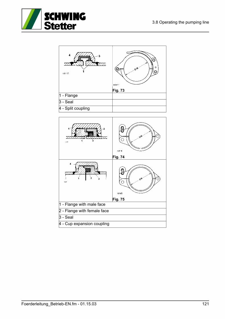
3.8 Operating the pumping line
Fig. 73 1 - Flange
3 - Seal
4 - Split coupling
Fig. 74
Fig. 75 1 - Flange with male face
2 - Flange with female face
3 - Seal
4 - Cup expansion coupling
Foerderleitung_Betrieb-EN.fm - 01.15.03 121
3.8 Operating the pumping line
3.8.12 Concrete pumping hoses
3.8.12.1 End hoses
An end hose is connected at the end of the pumping line for the distribution of the concrete.
GEFAHR! Danger!
Direct danger to life in the danger zone of the end hose!
Danger of death due to flapping end hose, spraying concrete and stones shooting out!
Always adhere to the required safety regulations!
Observe the following points in particular:
• The hose must hang freely when commencing pumping, when starting to pump again, and after blockages. No-one may remain in the danger zone of the end hose. The diameter of the danger zone is double the length of the end hose. It is prohibited to guide the end hose during pumping.
• Do NOT use fixed end pieces, reductions or extensions on the end hose!Connecting hoses with double-sided fixing are not permitted for use as end hos-es!
• Do NOT use a longer end hose!The maximum lengths and nominal sizes of the end hose are given for placing booms.
In exceptional cases, modifications and extensions are only permitted in strict ac-cordance with the manufacturer's instructions, see the "End hose modification op-tions" table in the ET catalogue. When using a longer end hose, the diameter of the danger zone also increases!
122 Foerderleitung_Betrieb-EN.fm - 01.15.03
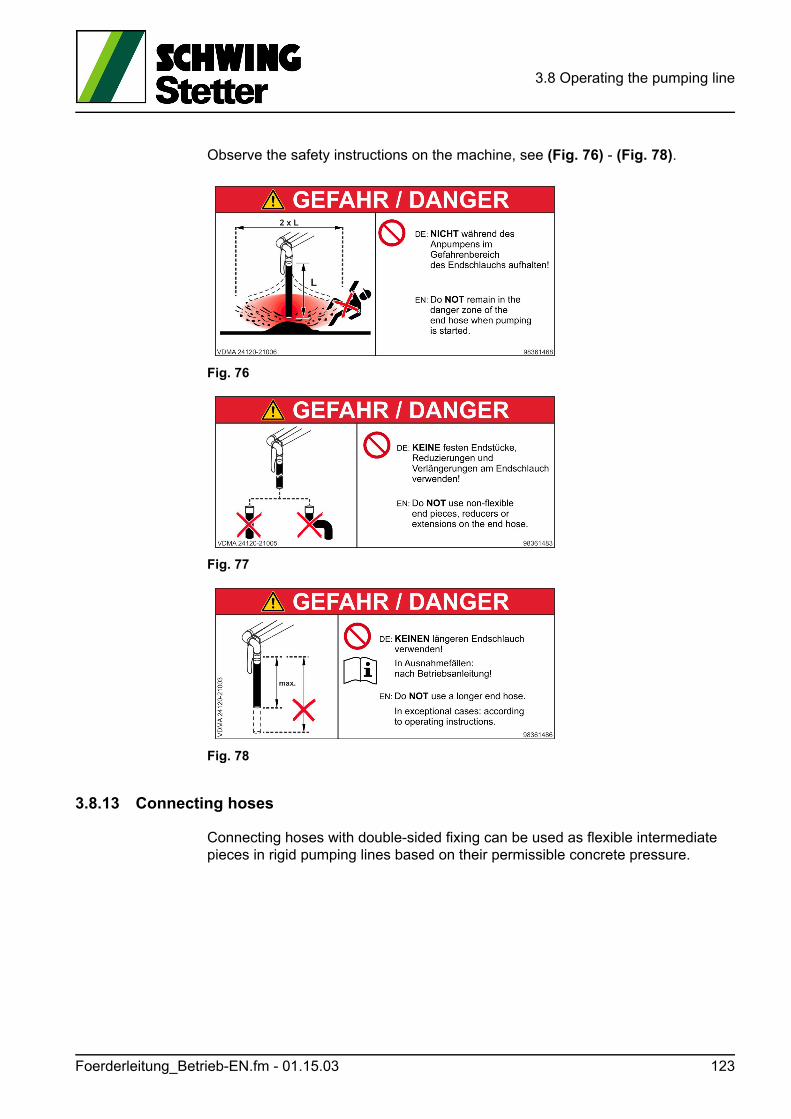
3.8 Operating the pumping line
Observe the safety instructions on the machine, see (Fig. 76) - (Fig. 78).
Fig. 76
Fig. 77
Fig. 78
3.8.13 Connecting hoses
Connecting hoses with double-sided fixing can be used as flexible intermediate pieces in rigid pumping lines based on their permissible concrete pressure.
Foerderleitung_Betrieb-EN.fm - 01.15.03 123
3.8 Operating the pumping line
3.8.14 Hose pipes
Multiple connecting hoses are often connected to hose pipes in mobile restoration operations.
The hoses are usually carried on a specially equipped truck-mounted concrete pump, installed before use and removed again after use.
3.8.14.1 Installing and operating a hose pipe
The installation of the hose line, as well as its operation, requires special care and expertise.
GEFAHR! Danger!
Danger to life due to flapping hoses!
Block off the danger zone and fix the hoses, cover hose in a suitable manner if re-quired!
In order to avoid a premature failure and possible accidents, ensure the following:
• Only use functional, clean hoses, couplings, seals, etc. of the same system to set up a hose pipe.
• The maximum possible concrete pressure of the concrete pump must not ex-ceed the permissible concrete pressure of all pumping line parts.
• The concreting personnel at the placement site must be aware of any potential dangers and be familiar with all necessary work.
• Install hoses in widest possible radius - do not bend(Radii that are too narrow cause abrasion on one side, thus allowing any bends to quickly destroy the hose. Narrow radii and bends encourage clogging and cause the hose to pulsate).
• Do not pull hoses, especially not over sharp edges.
• Do not twist hoses.
• Do not allow hoses to hang loose.
• Do not strike the hoses.
• Place hoses and fasten securely with belts. Do not use incising fixing parts.
• Do not drive over hoses. Place hose pipe in a protected manner.
• No unauthorised persons may remain near the hose pipe during pumping oper-ations
• Moisten hose with water, then pump with flow mixture.
• Always observe the maximum grain size, depending on the diameter of the hose.
• Pump at a low delivery rate, hose must remain still.
124 Foerderleitung_Betrieb-EN.fm - 01.15.03
3.8 Operating the pumping line
3.8.14.2 Cleaning the hose pipe
GEFAHR! Danger!
Direct danger to life due to flapping hoses!
Blowing out pumping hoses with compressed air is prohibited, see safety manual.
Hoses must be carefully cleaned after each use.
A thorough internal cleaning is especially important for this.
Dirty hoses wear out faster and cause clogging.
Suck back the cleaning ball, then knock off individual hoses and rinse thoroughly with water.
If it cannot be sucked back, knock off individual hoses, tip out and rinse thoroughly with water.
• Always make sure that the hose system is perfectly clean.
A clean hose helps prevent clogging.
Dried-up concrete can coalesce with rubber.
This means that not only the remaining concrete, but possibly a piece of rubber, will be pulled out during the next pumping.
Foerderleitung_Betrieb-EN.fm - 01.15.03 125

3.8 Operating the pumping line
126 Foerderleitung_Betrieb-EN.fm - 01.15.03
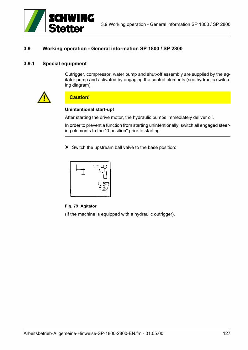
3.9 Working operation - General information SP 1800 / SP 2800
3.9 Working operation - General information SP 1800 / SP 2800
3.9.1 Special equipment
Outrigger, compressor, water pump and shut-off assembly are supplied by the ag-itator pump and activated by engaging the control elements (see hydraulic switch-ing diagram).
VORSICHT! Caution!
Unintentional start-up!
After starting the drive motor, the hydraulic pumps immediately deliver oil.
In order to prevent a function from starting unintentionally, switch all engaged steer-ing elements to the "0 position" prior to starting.
Switch the upstream ball valve to the base position:
Fig. 79 Agitator
(If the machine is equipped with a hydraulic outrigger).
Arbeitsbetrieb-Allgemeine-Hinweise-SP-1800-2800-EN.fm - 01.05.00 127
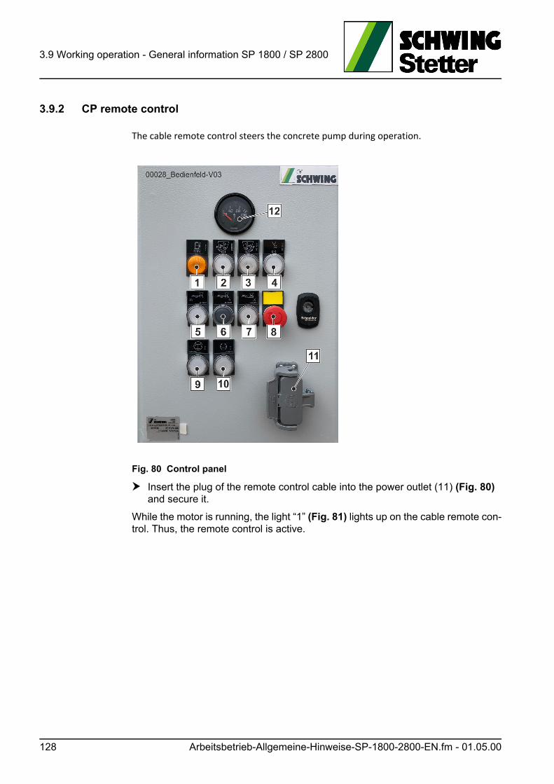
3.9 Working operation - General information SP 1800 / SP 2800
3.9.2 CP remote control
The cable remote control steers the concrete pump during operation.
Fig. 80 Control panel
Insert the plug of the remote control cable into the power outlet (11) (Fig. 80) and secure it.
While the motor is running, the light “1” (Fig. 81) lights up on the cable remote con-trol. Thus, the remote control is active.
128 Arbeitsbetrieb-Allgemeine-Hinweise-SP-1800-2800-EN.fm - 01.05.00
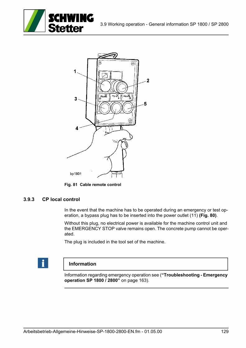
3.9 Working operation - General information SP 1800 / SP 2800
Fig. 81 Cable remote control
3.9.3 CP local control
In the event that the machine has to be operated during an emergency or test op-eration, a bypass plug has to be inserted into the power outlet (11) (Fig. 80).
Without this plug, no electrical power is available for the machine control unit and the EMERGENCY STOP valve remains open. The concrete pump cannot be oper-ated.
The plug is included in the tool set of the machine.
Information
Information regarding emergency operation see (“Troubleshooting - Emergency operation SP 1800 / 2800” on page 163).
Arbeitsbetrieb-Allgemeine-Hinweise-SP-1800-2800-EN.fm - 01.05.00 129
3.9 Working operation - General information SP 1800 / SP 2800
3.9.4 Close maintenance flaps
VORSICHT! Caution!
Hearing can be damaged!
Personal hearing protection must always be worn when a sound pressure level of 80 dB(A) is exceeded.
Failure to observe this may be harmful to your health.
Close all hoods, covers etc. that are provided to insulate the noise!
(see “Noise information” on page 43).
Furthermore, the flaps must be closed, in order to protect the machine from clog-ging and complicate unauthorised access to the machine.
130 Arbeitsbetrieb-Allgemeine-Hinweise-SP-1800-2800-EN.fm - 01.05.00
3.10 Working operation - Concrete pump SP 1800 / 2800
3.10 Working operation - Concrete pump SP 1800 / 2800
3.10.1 General
• Lightly spray the concrete filling hopper with mould oil from the outside before pumping for the first time. This facilitates subsequent cleaning.
Make sure that no oil enters the hopper (risk of changes to concrete).
Use only rubber-compatible media.
• Switch on the agitator and vibrator.
• Fill a lubrication mixture into the concrete filling hopper.
The lubrication mixture consists of two parts cement, one part sand, and one part water.
The amount is determined by the length and diameter of the pumping line.
If you have a short pumping line or are pumping ready-mix concrete, the lubri-cation mixture may consist solely of cement and water.
• Never switch on the concrete pump with an empty filling hopper. Dry running wears out the pumping piston and kidney seal faster. Fill water into the filling hopper for maintenance and cleaning work.
• Fill concrete into the filling hopper before the lubrication mixture has been com-pletely pumped out.
• Never pump at full speed; instead, set the required pumping power after con-crete starts to exit the end of the pumping line.
VORSICHT! Caution!
Risk of accidents due to parts or material being ejected!
Intake air is compressed in the pumping line and escapes abruptly at the end of the line or through the hopper.
Persons in the danger zone may be injured through pulsating of the end hose and flying parts.
To avoid this, the hopper must be filled up to the agitator shaft with concrete so that no air is drawn in.
• In case of wait times, especially in hot weather, keep the concrete moving (ag-itate it) by pumping it back and forth from time to time.
• Spray off the machine occasionally with water during operation to prevent con-crete from setting.
Arbeitsbetrieb-Betonpumpe-SP-1800-2800-EN.fm - 01.05.00 131
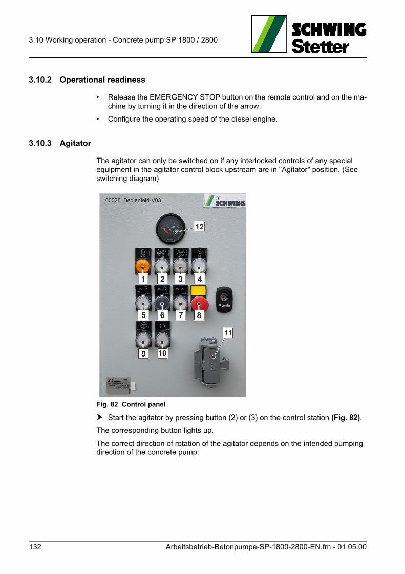
3.10 Working operation - Concrete pump SP 1800 / 2800
3.10.2 Operational readiness
• Release the EMERGENCY STOP button on the remote control and on the ma-chine by turning it in the direction of the arrow.
• Configure the operating speed of the diesel engine.
3.10.3 Agitator
The agitator can only be switched on if any interlocked controls of any special equipment in the agitator control block upstream are in "Agitator" position. (See switching diagram)
Fig. 82 Control panel
Start the agitator by pressing button (2) or (3) on the control station (Fig. 82).
The corresponding button lights up.
The correct direction of rotation of the agitator depends on the intended pumping direction of the concrete pump:
132 Arbeitsbetrieb-Betonpumpe-SP-1800-2800-EN.fm - 01.05.00
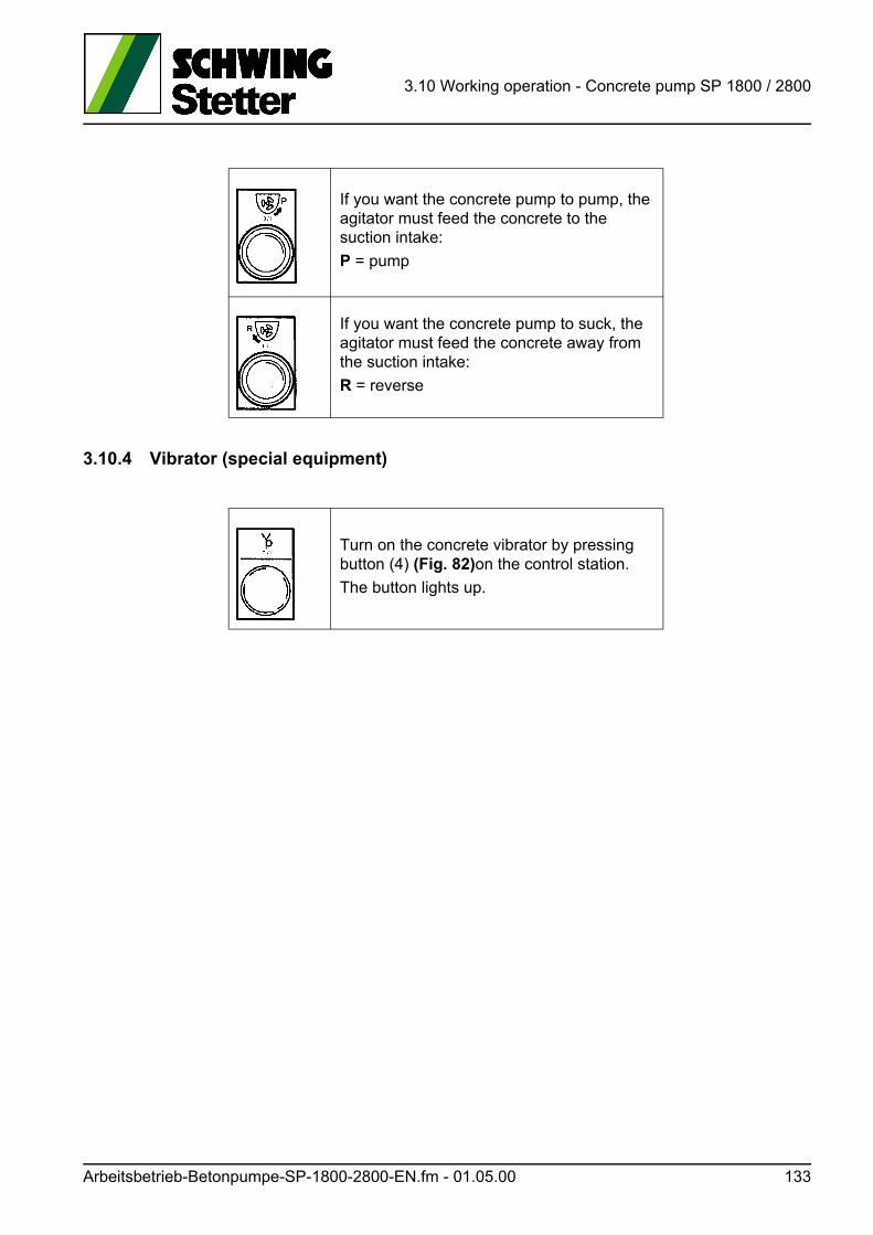
3.10 Working operation - Concrete pump SP 1800 / 2800
3.10.4 Vibrator (special equipment)
If you want the concrete pump to pump, the agitator must feed the concrete to the suction intake:
P = pump
If you want the concrete pump to suck, the agitator must feed the concrete away from the suction intake:
R = reverse
Turn on the concrete vibrator by pressing button (4) (Fig. 82)on the control station.
The button lights up.
Arbeitsbetrieb-Betonpumpe-SP-1800-2800-EN.fm - 01.05.00 133
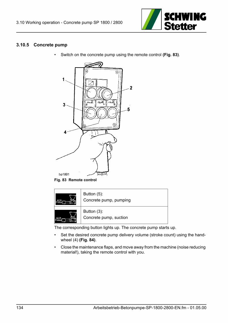
3.10 Working operation - Concrete pump SP 1800 / 2800
3.10.5 Concrete pump
• Switch on the concrete pump using the remote control (Fig. 83).
Fig. 83 Remote control
The corresponding button lights up. The concrete pump starts up.
• Set the desired concrete pump delivery volume (stroke count) using the hand-wheel (4) (Fig. 84).
• Close the maintenance flaps, and move away from the machine (noise reducing material!), taking the remote control with you.
Button (5):
Concrete pump, pumping
Button (3):
Concrete pump, suction
134 Arbeitsbetrieb-Betonpumpe-SP-1800-2800-EN.fm - 01.05.00

3.10 Working operation - Concrete pump SP 1800 / 2800
Fig. 84 Maintenance flaps on right in direction of travel
3.10.6 Switching off the concrete pump, agitator and special equipment
• Switch off the concrete pump by pressing the button (4) (Fig. 83).
• Switch off the agitator and concrete vibrator by pressing the corresponding illu-minated buttons on the control station.
• Switch off any special equipment by turning the corresponding controls to the "Agitator" position.
3.10.7 Reconnecting the concrete pump
The machine can be adjusted for high concrete delivery volumes or for high con-crete pressures, according to operating conditions.
The adjustment is made by changing the existing hydraulic hose coupling assign-ments:
Fig. 85 Piston-side pressure
Piston-side pressure (Fig. 85) + (Fig. 86)
High concrete pressure
Rod-side pressure (Fig. 87) + (Fig. 88)
High concrete delivery volume
Arbeitsbetrieb-Betonpumpe-SP-1800-2800-EN.fm - 01.05.00 135
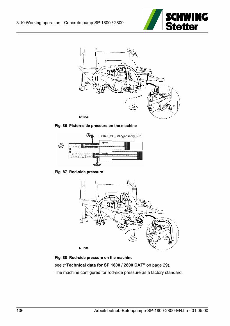
3.10 Working operation - Concrete pump SP 1800 / 2800
Fig. 86 Piston-side pressure on the machine
Fig. 87 Rod-side pressure
Fig. 88 Rod-side pressure on the machine
see (“Technical data for SP 1800 / 2800 CAT” on page 29).
The machine configured for rod-side pressure as a factory standard.
136 Arbeitsbetrieb-Betonpumpe-SP-1800-2800-EN.fm - 01.05.00
3.10 Working operation - Concrete pump SP 1800 / 2800
WARNUNG! Warning!
The concrete pump must only be reconfigured by qualified personnel.
• Work only on the unpressurised hydraulic system.
• Switch off the motor and secure it against being switched back on.
ACHTUNG! Attention!
Ensure that the pumping line material is suitable for the potential concrete pressure!
• Collect any escaping hydraulic oil.
• Check all disconnected parts and immediately replace any damaged parts.
• Check the oil level and perform a test run.
• Check for leaks and check the oil level after the test run.
Arbeitsbetrieb-Betonpumpe-SP-1800-2800-EN.fm - 01.05.00 137

3.10 Working operation - Concrete pump SP 1800 / 2800
138 Arbeitsbetrieb-Betonpumpe-SP-1800-2800-EN.fm - 01.05.00
3.11 Working operation - Auxiliary power units
3.11 Working operation - Auxiliary power units
The hydraulic pump for the agitator supplies various types of special equipment, if necessary, for example:
• Hydraulic outrigger
• Water system (water pump)
• Air system (compressor)
• Hydraulic control unit (e.g.: hydraulic shut-off assembly*)
Switching the corresponding directional valve accordingly ensures that either the agitator or the special equipment can be operated. See switching diagram.
The simultaneous operation of agitator and special equipment, as well as various special equipment, is not possible.
VORSICHT! Caution!
Unintentional start-up!
After switching on the drive motor, the auxiliary pump (agitator pump) pumps oil im-mediately.
However, the agitator only starts after being switched over electrically using the corresponding buttons on the control station of the agitator control block.
Any special equipment can start though because the respective control valve is lo-cated in the oil flow in front of the agitator control block.
For this reason:
• Always switch off the agitator electrically prior to starting any special equipment.
• Switch off each piece of special equipment immediately after use using the hy-draulic control element (default position: agitator).
This will prevent the aggregates from running unintentionally when starting the mo-tor or switching functions. Unnecessary oil heating is prevented.
Arbeitsbetrieb-Hilfsaggregate-EN.fm - 01.05.00 139
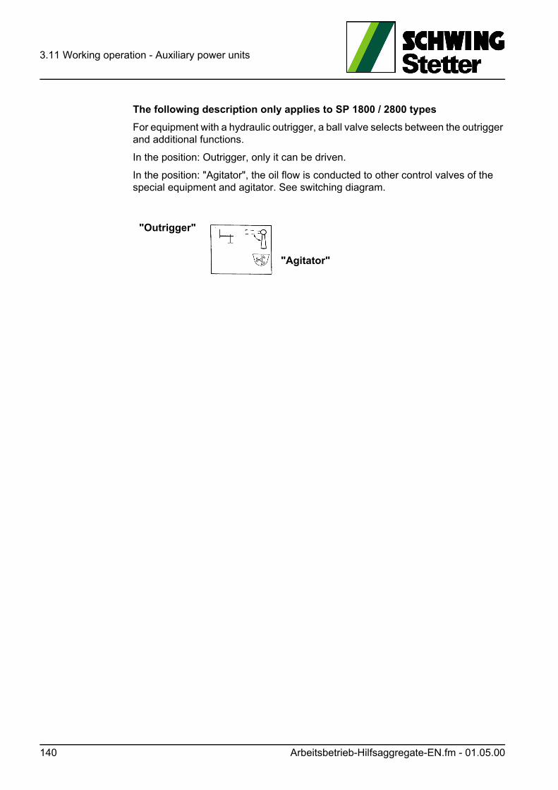
3.11 Working operation - Auxiliary power units
The following description only applies to SP 1800 / 2800 types
For equipment with a hydraulic outrigger, a ball valve selects between the outrigger and additional functions.
In the position: Outrigger, only it can be driven.
In the position: "Agitator", the oil flow is conducted to other control valves of the special equipment and agitator. See switching diagram.
"Outrigger"
"Agitator"
140 Arbeitsbetrieb-Hilfsaggregate-EN.fm - 01.05.00
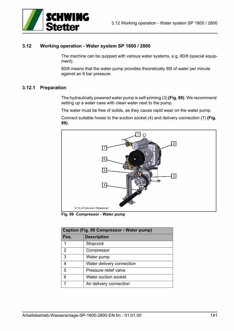
3.12 Working operation - Water system SP 1800 / 2800
3.12 Working operation - Water system SP 1800 / 2800
The machine can be quipped with various water systems, e.g. 80/8 (special equip-ment).
80/8 means that the water pump provides theoretically 80l of water per minute against an 8 bar pressure.
3.12.1 Preparation
The hydraulically powered water pump is self-priming (3) (Fig. 89). We recommend setting up a water case with clean water next to the pump.
The water must be free of solids, as they cause rapid wear on the water pump.
Connect suitable hoses to the suction socket (4) and delivery connection (7) (Fig. 89).
Fig. 89 Compressor - Water pump
Caption (Fig. 89 Compressor - Water pump)
Pos. Description
1 Stopcock
2 Compressor
3 Water pump
4 Water delivery connection
5 Pressure relief valve
6 Water suction socket
7 Air delivery connection
Arbeitsbetrieb-Wasseranlage-SP-1800-2800-EN.fm - 01.01.00 141
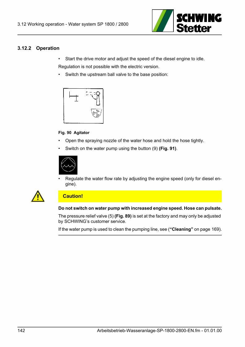
3.12 Working operation - Water system SP 1800 / 2800
3.12.2 Operation
• Start the drive motor and adjust the speed of the diesel engine to idle.
Regulation is not possible with the electric version.
• Switch the upstream ball valve to the base position:
Fig. 90 Agitator
• Open the spraying nozzle of the water hose and hold the hose tightly.
• Switch on the water pump using the button (9) (Fig. 91).
• Regulate the water flow rate by adjusting the engine speed (only for diesel en-gine).
VORSICHT! Caution!
Do not switch on water pump with increased engine speed. Hose can pulsate.
The pressure relief valve (5) (Fig. 89) is set at the factory and may only be adjusted by SCHWING’s customer service.
If the water pump is used to clean the pumping line, see (“Cleaning” on page 169).
142 Arbeitsbetrieb-Wasseranlage-SP-1800-2800-EN.fm - 01.01.00
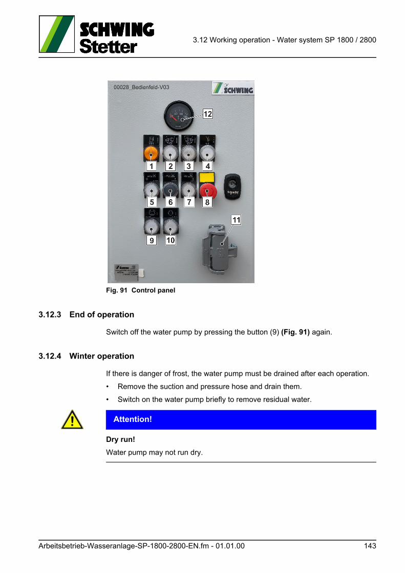
3.12 Working operation - Water system SP 1800 / 2800
Fig. 91 Control panel
3.12.3 End of operation
Switch off the water pump by pressing the button (9) (Fig. 91) again.
3.12.4 Winter operation
If there is danger of frost, the water pump must be drained after each operation.
• Remove the suction and pressure hose and drain them.
• Switch on the water pump briefly to remove residual water.
ACHTUNG! Attention!
Dry run!
Water pump may not run dry.
Arbeitsbetrieb-Wasseranlage-SP-1800-2800-EN.fm - 01.01.00 143

3.12 Working operation - Water system SP 1800 / 2800
144 Arbeitsbetrieb-Wasseranlage-SP-1800-2800-EN.fm - 01.01.00
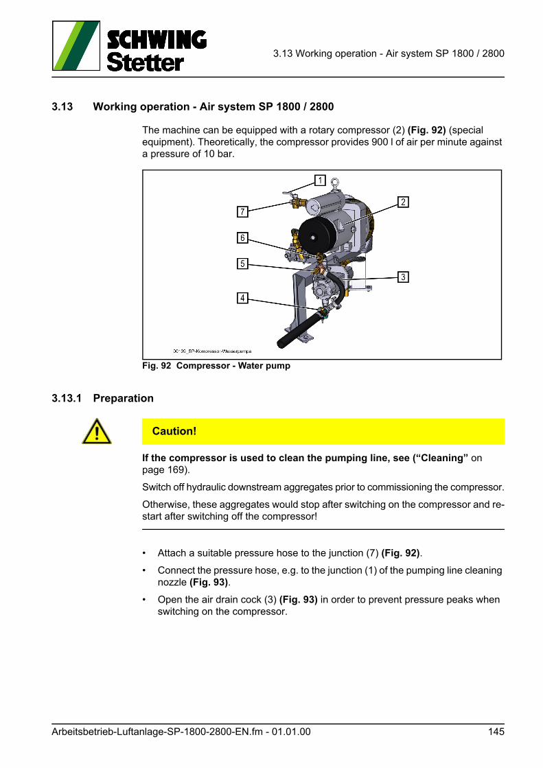
3.13 Working operation - Air system SP 1800 / 2800
3.13 Working operation - Air system SP 1800 / 2800
The machine can be equipped with a rotary compressor (2) (Fig. 92) (special equipment). Theoretically, the compressor provides 900 l of air per minute against a pressure of 10 bar.
Fig. 92 Compressor - Water pump
3.13.1 Preparation
VORSICHT! Caution!
If the compressor is used to clean the pumping line, see (“Cleaning” on page 169).
Switch off hydraulic downstream aggregates prior to commissioning the compressor.
Otherwise, these aggregates would stop after switching on the compressor and re-start after switching off the compressor!
• Attach a suitable pressure hose to the junction (7) (Fig. 92).
• Connect the pressure hose, e.g. to the junction (1) of the pumping line cleaning nozzle (Fig. 93).
• Open the air drain cock (3) (Fig. 93) in order to prevent pressure peaks when switching on the compressor.
Arbeitsbetrieb-Luftanlage-SP-1800-2800-EN.fm - 01.01.00 145
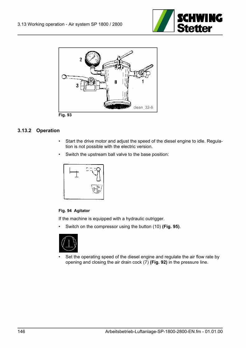
3.13 Working operation - Air system SP 1800 / 2800
Fig. 93
3.13.2 Operation
• Start the drive motor and adjust the speed of the diesel engine to idle. Regula-tion is not possible with the electric version.
• Switch the upstream ball valve to the base position:
Fig. 94 Agitator
If the machine is equipped with a hydraulic outrigger.
• Switch on the compressor using the button (10) (Fig. 95).
• Set the operating speed of the diesel engine and regulate the air flow rate by opening and closing the air drain cock (7) (Fig. 92) in the pressure line.
146 Arbeitsbetrieb-Luftanlage-SP-1800-2800-EN.fm - 01.01.00
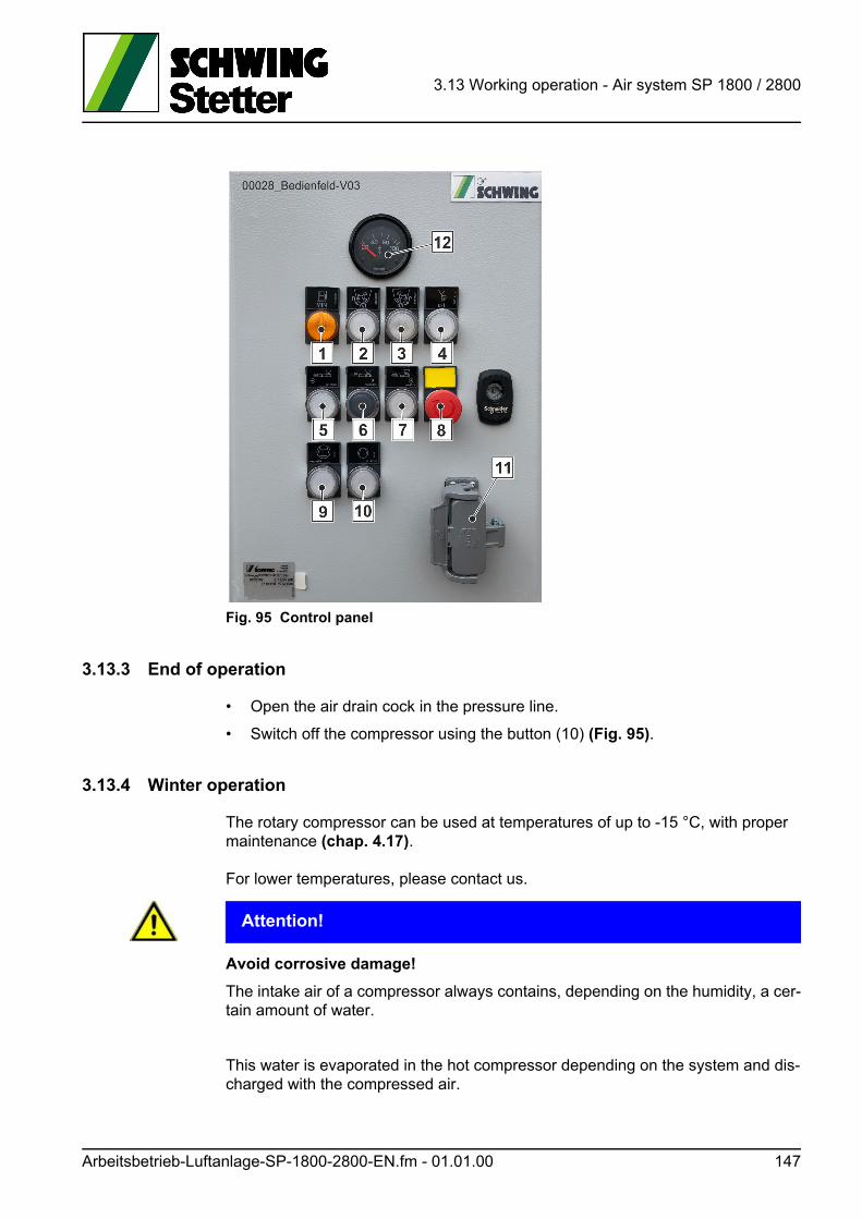
3.13 Working operation - Air system SP 1800 / 2800
Fig. 95 Control panel
3.13.3 End of operation
• Open the air drain cock in the pressure line.
• Switch off the compressor using the button (10) (Fig. 95).
3.13.4 Winter operation
The rotary compressor can be used at temperatures of up to -15 °C, with proper maintenance (chap. 4.17).
For lower temperatures, please contact us.
ACHTUNG! Attention!
Avoid corrosive damage!
The intake air of a compressor always contains, depending on the humidity, a cer-tain amount of water.
This water is evaporated in the hot compressor depending on the system and dis-charged with the compressed air.
Arbeitsbetrieb-Luftanlage-SP-1800-2800-EN.fm - 01.01.00 147
3.13 Working operation - Air system SP 1800 / 2800
With the use (cleaning of the pumping line) typical for the concrete pump operation, the short duty cycle is often not sufficient to bring the compressor up to operating temperature.
Water can collect in the compressor (2) (Fig. 92) and cause damage.
For this reason, we recommend:
• Switching on the compressor once a week for at least 30 minutes continuously.
• Adhering to the maintenance intervals for the compressor.
• Only using original spare parts and the prescribed compressor oil when servic-ing your compressor.
Our maintenance packages:
10170389 (standard maintenance) and
10170388 (oil separator cartridge)
contain all of the spare parts needed to service your compressor, including the compressor oil.
148 Arbeitsbetrieb-Luftanlage-SP-1800-2800-EN.fm - 01.01.00
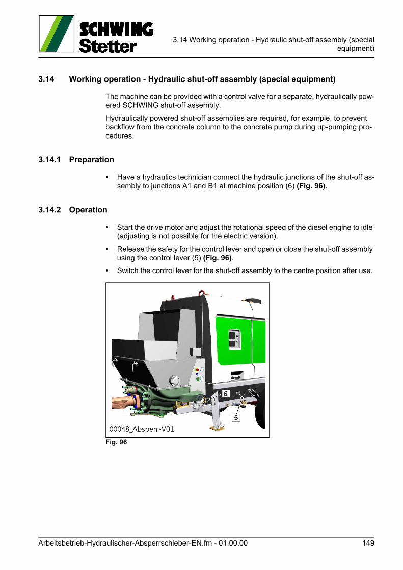
3.14 Working operation - Hydraulic shut-off assembly (specialequipment)
3.14 Working operation - Hydraulic shut-off assembly (special equipment)
The machine can be provided with a control valve for a separate, hydraulically pow-ered SCHWING shut-off assembly.
Hydraulically powered shut-off assemblies are required, for example, to prevent backflow from the concrete column to the concrete pump during up-pumping pro-cedures.
3.14.1 Preparation
• Have a hydraulics technician connect the hydraulic junctions of the shut-off as-sembly to junctions A1 and B1 at machine position (6) (Fig. 96).
3.14.2 Operation
• Start the drive motor and adjust the rotational speed of the diesel engine to idle (adjusting is not possible for the electric version).
• Release the safety for the control lever and open or close the shut-off assembly using the control lever (5) (Fig. 96).
• Switch the control lever for the shut-off assembly to the centre position after use.
Fig. 96
Arbeitsbetrieb-Hydraulischer-Absperrschieber-EN.fm - 01.00.00 149
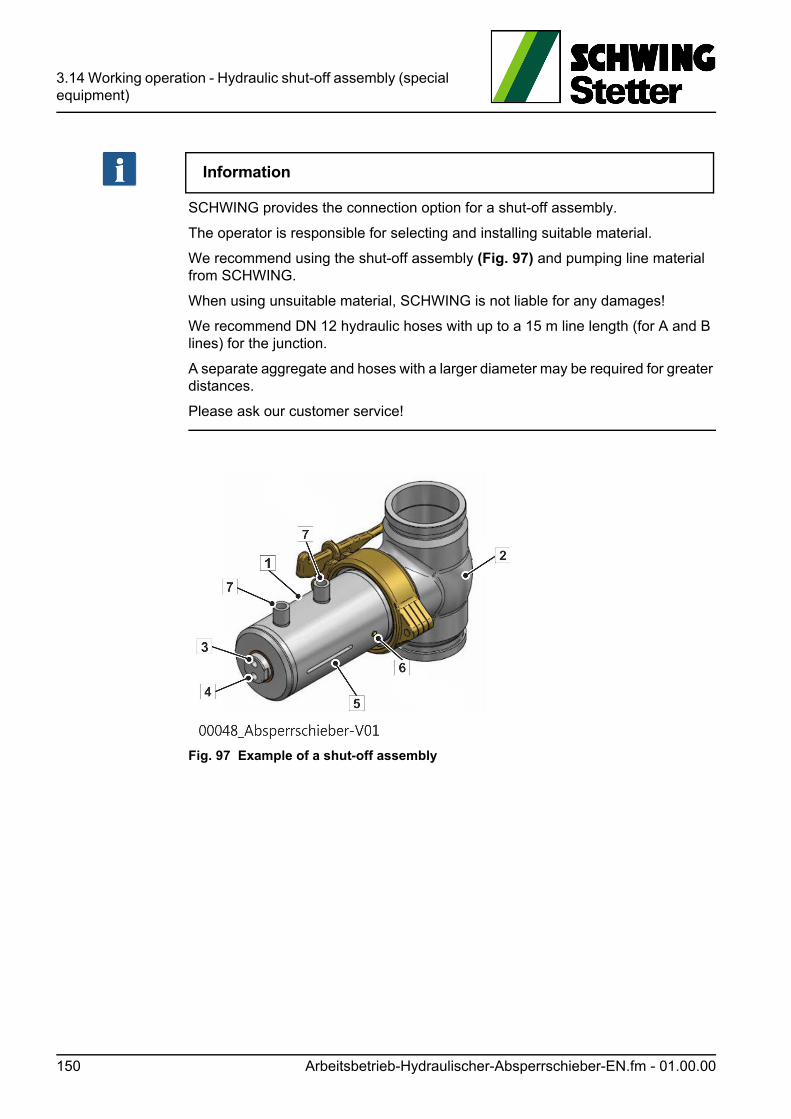
3.14 Working operation - Hydraulic shut-off assembly (special equipment)
Information
SCHWING provides the connection option for a shut-off assembly.
The operator is responsible for selecting and installing suitable material.
We recommend using the shut-off assembly (Fig. 97) and pumping line material from SCHWING.
When using unsuitable material, SCHWING is not liable for any damages!
We recommend DN 12 hydraulic hoses with up to a 15 m line length (for A and B lines) for the junction.
A separate aggregate and hoses with a larger diameter may be required for greater distances.
Please ask our customer service!
Fig. 97 Example of a shut-off assembly
150 Arbeitsbetrieb-Hydraulischer-Absperrschieber-EN.fm - 01.00.00

3.15 Clearing blockages
3.15 Clearing blockages
GEFAHR! Danger!
Danger to life due to suspended loads!
If interventions are required in the machine technology to release blockages, which go beyond the measures described below, these may only be carried out by qual-ified personnel.
The following must be observed in the process:
• Only work on unpressurised hydraulic systems. Although pressure relief valves help prevent the machine from overloading, the hydraulic system is under pres-sure when tripping the release of pressure.
• Switch off the drive and secure it against being switched back on. Release the hydraulic system. This can be done, for example, by opening manual relief valves or also by repeated manual switching of the appropriate directional valve in both directions.
In contrast to a pressure test, an uncontrolled blockage of the machine occurring during operation is considered a serious incident.
If the energy stored during the blockage is suddenly released, it can cause serious accidents due to autonomous movements of the machine or the failure of compo-nents.
Even the use of inappropriate measures to clear such blockages can suddenly re-lease the stored energy and cause serious accidents.
GEFAHR! Danger!
Danger from uncontrolled movements!
Proceed as follows during an uncontrolled blockage:
• In case of danger, immediately press an EMERGENCY STOP button!
• Remain calm!
• Try to locate the blockage!
Lösen-von-Blockierungen-EN.fm - 01.01.01 151
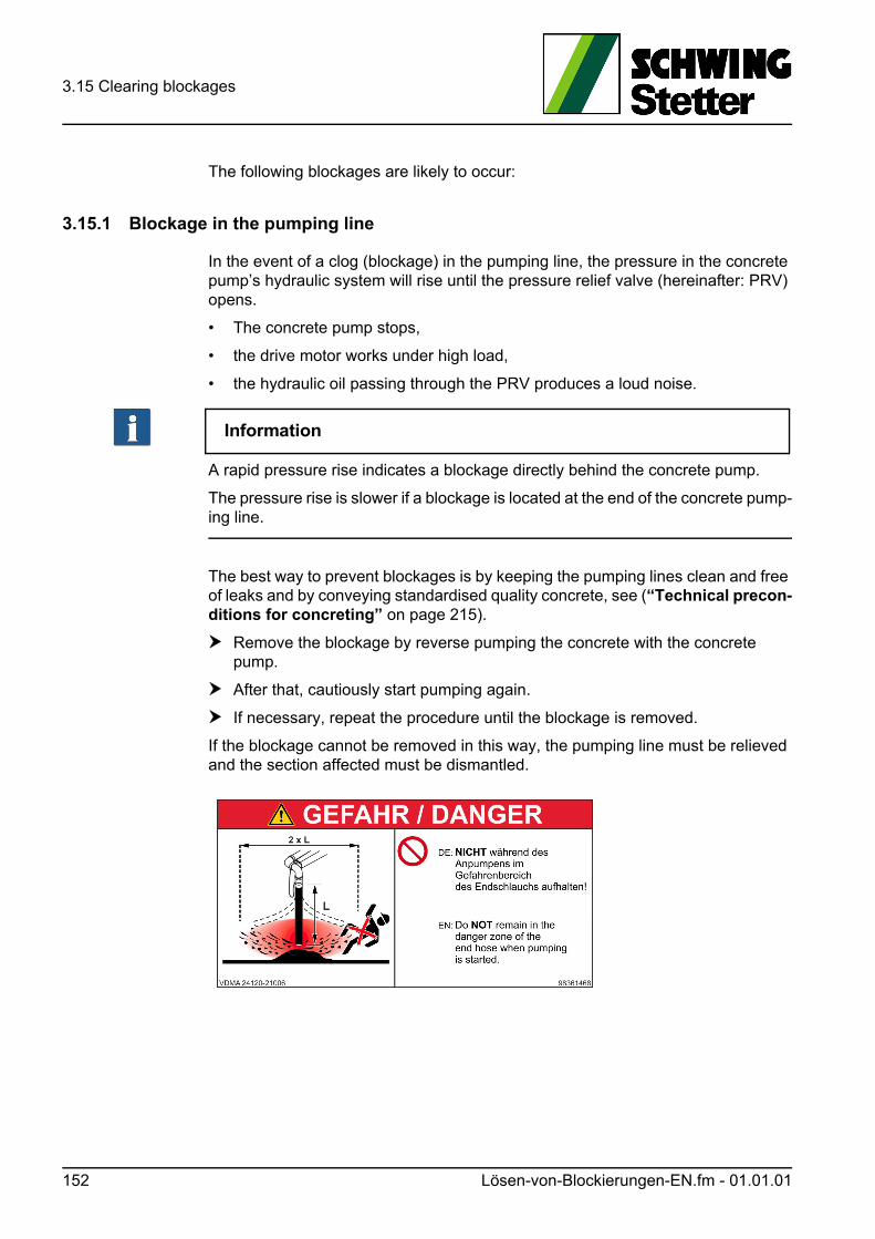
3.15 Clearing blockages
The following blockages are likely to occur:
3.15.1 Blockage in the pumping line
In the event of a clog (blockage) in the pumping line, the pressure in the concrete pump’s hydraulic system will rise until the pressure relief valve (hereinafter: PRV) opens.
• The concrete pump stops,
• the drive motor works under high load,
• the hydraulic oil passing through the PRV produces a loud noise.
Information
A rapid pressure rise indicates a blockage directly behind the concrete pump.
The pressure rise is slower if a blockage is located at the end of the concrete pump-ing line.
The best way to prevent blockages is by keeping the pumping lines clean and free of leaks and by conveying standardised quality concrete, see (“Technical precon-ditions for concreting” on page 215).
Remove the blockage by reverse pumping the concrete with the concrete pump.
After that, cautiously start pumping again.
If necessary, repeat the procedure until the blockage is removed.
If the blockage cannot be removed in this way, the pumping line must be relieved and the section affected must be dismantled.
152 Lösen-von-Blockierungen-EN.fm - 01.01.01
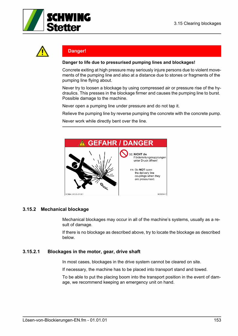
3.15 Clearing blockages
GEFAHR! Danger!
Danger to life due to pressurised pumping lines and blockages!
Concrete exiting at high pressure may seriously injure persons due to violent move-ments of the pumping line and also at a distance due to stones or fragments of the pumping line flying about.
Never try to loosen a blockage by using compressed air or pressure rise of the hy-draulics. This presses in the blockage firmer and causes the pumping line to burst. Possible damage to the machine.
Never open a pumping line under pressure and do not tap it.
Relieve the pumping line by reverse pumping the concrete with the concrete pump.
Never work while directly bent over the line.
3.15.2 Mechanical blockage
Mechanical blockages may occur in all of the machine’s systems, usually as a re-sult of damage.
If there is no blockage as described above, try to locate the blockage as described below.
3.15.2.1 Blockages in the motor, gear, drive shaft
In most cases, blockages in the drive system cannot be cleared on site.
If necessary, the machine has to be placed into transport stand and towed.
To be able to put the placing boom into the transport position in the event of dam-age, we recommend keeping an emergency unit on hand.
Lösen-von-Blockierungen-EN.fm - 01.01.01 153
3.15 Clearing blockages
3.15.2.2 Blockages in the control system
Blockages in the hydraulic pilot control system are often caused by dirt in the hy-draulic oil.
This dirt causes the control piston to jam and in turn to not execute control com-mands or to execute them incorrectly.
A clogging of the oil is prevented through careful oil maintenance (filter change). Metallic abrasion in the oil points to damage.
Control blocks may also jam due to high temperature differences, for example, when feeding hot hydraulic oil to a cold control block in winter.
This can be avoided by heating the hydraulic system.
If control commands are not carried out properly.
Immediately actuate an EMERGENCY STOP button.
Use the emergency operation system to move the machine into the transport position, see (“Clearing blockages” on page 151).
154 Lösen-von-Blockierungen-EN.fm - 01.01.01
3.16 Control of operations SP 1800/2800
3.16 Control of operations SP 1800/2800
Pressing an EMERGENCY-STOP button interrupts the main hydraulic functions, see (“EMERGENCY-STOP system for SP 1800 / 2800” on page 77).
• Pay attention to unusual noises, vibrations, etc. caused by the machine. There may be a damage that could be localised through timely repair.
• Check the stability and horizontal position of the machine and correct its posi-tion if necessary. All supporting dishes must be constantly, firmly on the ground.
• Ensure that there are no leaks in the pumping pipe connections. Fix leaks as quickly as possible. Bleeding the concrete results in clogging.
3.16.1 Control of operations for concrete pump
VORSICHT! Caution!
Risk of accidents due to parts or material being ejected!
Intake air is compressed in the pumping line and escapes abruptly at the end of the line or through the hopper.
Persons in the danger zone may be injured through pulsating of the end hose and flying parts.
To avoid this, the hopper must be filled up to the agitator shaft with concrete so that no air is drawn in.
Otherwise, drawn-in air causes the concrete to spatter and dry running increases the wear on the pumping pistons and kidney seal.
• Check the hydraulic oil level. The oil level must be visible at the top of the level indicator (1) (Fig. 98) when the drive is not running.
• Check the hydraulic oil temperature (1) (Fig. 99) on the thermometer.
• If the temperature rises above 80 °C, the pumping speed must reduced. Shut down the machine, top up oil or check cooling, if necessary.
Betriebsueberwachung-SP-1800-2800-EN.fm - 01.00.00 155
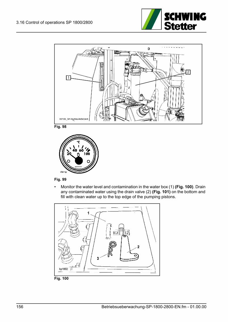
3.16 Control of operations SP 1800/2800
Fig. 98
Fig. 99
• Monitor the water level and contamination in the water box (1) (Fig. 100). Drain any contaminated water using the drain valve (2) (Fig. 101) on the bottom and fill with clean water up to the top edge of the pumping pistons.
Fig. 100
156 Betriebsueberwachung-SP-1800-2800-EN.fm - 01.00.00
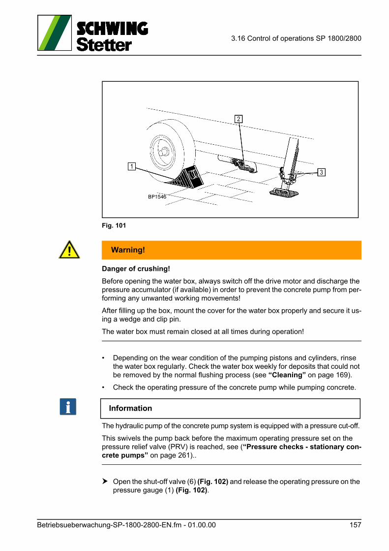
3.16 Control of operations SP 1800/2800
Fig. 101
WARNUNG! Warning!
Danger of crushing!
Before opening the water box, always switch off the drive motor and discharge the pressure accumulator (if available) in order to prevent the concrete pump from per-forming any unwanted working movements!
After filling up the box, mount the cover for the water box properly and secure it us-ing a wedge and clip pin.
The water box must remain closed at all times during operation!
• Depending on the wear condition of the pumping pistons and cylinders, rinse the water box regularly. Check the water box weekly for deposits that could not be removed by the normal flushing process (see “Cleaning” on page 169).
• Check the operating pressure of the concrete pump while pumping concrete.
Information
The hydraulic pump of the concrete pump system is equipped with a pressure cut-off.
This swivels the pump back before the maximum operating pressure set on the pressure relief valve (PRV) is reached, see (“Pressure checks - stationary con-crete pumps” on page 261)..
Open the shut-off valve (6) (Fig. 102) and release the operating pressure on the pressure gauge (1) (Fig. 102).
Betriebsueberwachung-SP-1800-2800-EN.fm - 01.00.00 157
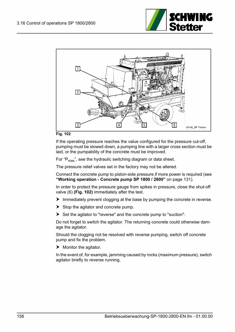
3.16 Control of operations SP 1800/2800
Fig. 102
If the operating pressure reaches the value configured for the pressure cut-off, pumping must be slowed down, a pumping line with a larger cross section must be laid, or the pumpability of the concrete must be improved.
For “Pmax”, see the hydraulic switching diagram or data sheet.
The pressure relief valves set in the factory may not be altered.
Connect the concrete pump to piston-side pressure if more power is required (see “Working operation - Concrete pump SP 1800 / 2800” on page 131).
In order to protect the pressure gauge from spikes in pressure, close the shut-off valve (6) (Fig. 102) immediately after the test.
Immediately prevent clogging at the base by pumping the concrete in reverse.
Stop the agitator and concrete pump.
Set the agitator to "reverse" and the concrete pump to "suction".
Do not forget to switch the agitator. The returning concrete could otherwise dam-age the agitator.
Should the clogging not be resolved with reverse pumping, switch off concrete pump and fix the problem.
Monitor the agitator.
In the event of, for example, jamming caused by rocks (maximum pressure), switch agitator briefly to reverse running.
158 Betriebsueberwachung-SP-1800-2800-EN.fm - 01.00.00
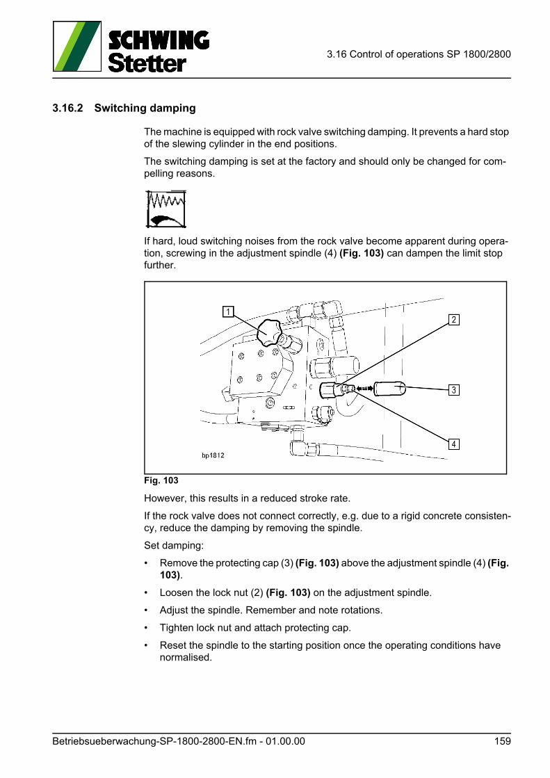
3.16 Control of operations SP 1800/2800
3.16.2 Switching damping
The machine is equipped with rock valve switching damping. It prevents a hard stop of the slewing cylinder in the end positions.
The switching damping is set at the factory and should only be changed for com-pelling reasons.
If hard, loud switching noises from the rock valve become apparent during opera-tion, screwing in the adjustment spindle (4) (Fig. 103) can dampen the limit stop further.
Fig. 103
However, this results in a reduced stroke rate.
If the rock valve does not connect correctly, e.g. due to a rigid concrete consisten-cy, reduce the damping by removing the spindle.
Set damping:
• Remove the protecting cap (3) (Fig. 103) above the adjustment spindle (4) (Fig. 103).
• Loosen the lock nut (2) (Fig. 103) on the adjustment spindle.
• Adjust the spindle. Remember and note rotations.
• Tighten lock nut and attach protecting cap.
• Reset the spindle to the starting position once the operating conditions have normalised.
Betriebsueberwachung-SP-1800-2800-EN.fm - 01.00.00 159
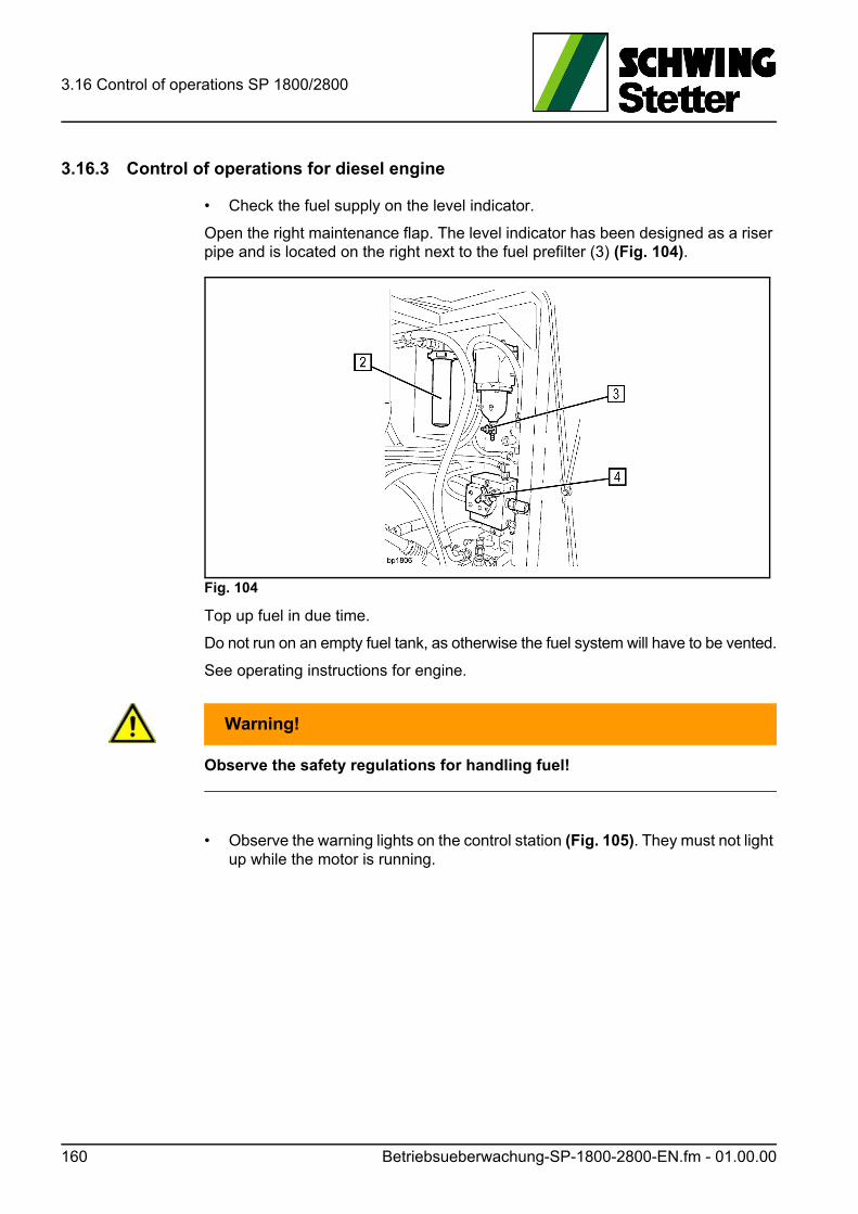
3.16 Control of operations SP 1800/2800
3.16.3 Control of operations for diesel engine
• Check the fuel supply on the level indicator.
Open the right maintenance flap. The level indicator has been designed as a riser pipe and is located on the right next to the fuel prefilter (3) (Fig. 104).
Fig. 104
Top up fuel in due time.
Do not run on an empty fuel tank, as otherwise the fuel system will have to be vented.
See operating instructions for engine.
WARNUNG! Warning!
Observe the safety regulations for handling fuel!
• Observe the warning lights on the control station (Fig. 105). They must not light up while the motor is running.
160 Betriebsueberwachung-SP-1800-2800-EN.fm - 01.00.00
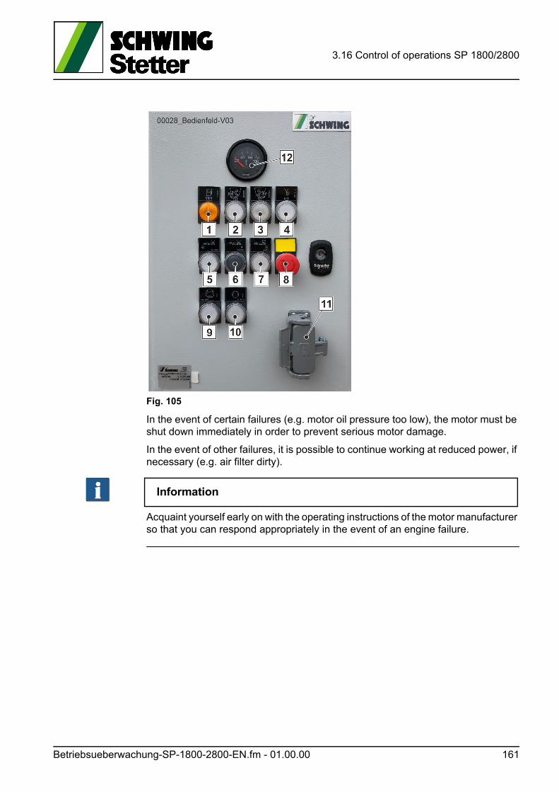
3.16 Control of operations SP 1800/2800
Fig. 105
In the event of certain failures (e.g. motor oil pressure too low), the motor must be shut down immediately in order to prevent serious motor damage.
In the event of other failures, it is possible to continue working at reduced power, if necessary (e.g. air filter dirty).
Information
Acquaint yourself early on with the operating instructions of the motor manufacturer so that you can respond appropriately in the event of an engine failure.
Betriebsueberwachung-SP-1800-2800-EN.fm - 01.00.00 161

3.16 Control of operations SP 1800/2800
162 Betriebsueberwachung-SP-1800-2800-EN.fm - 01.00.00
3.17 Troubleshooting - Emergency operation SP 1800 / 2800
3.17 Troubleshooting - Emergency operation SP 1800 / 2800
3.17.1 Control failure
If a functional failure occurs, first check whether:
• An EMERGENCY-STOP button has been actuated.
• The grid assembly in the agitator hopper is raised.
• A fuse has been triggered.
• The magnets of the respective control valves are supplied with power.
Information
The plugs of the control valve magnets are equipped with light-emitting diodes for troubleshooting purposes, which should light up when connected to a power source.
3.17.2 Electrical fuse protection for the machine control system
Depending on the type of machine, the system can be secured in several places:
• A main safety fuse near the starter.
• Safety fuses in the switch cabinet or operator station of the concrete pump (Fig. 106).
Also see electrical circuit diagram.
Check fuses:
• Switch off the motor and remove the ignition key.
• Open the top cover of the control station using the special key.
- Commercially available vehicle fuses are used.
Only insert newly equivalent fuses.
ACHTUNG! Attention!
Material damage caused by overrated fuses!
The electrical system is destroyed due to overrated and overridden fuses.
Verhalten-bei-Stoerungen-SP-1800-2800-EN.fm - 01.04.00 163
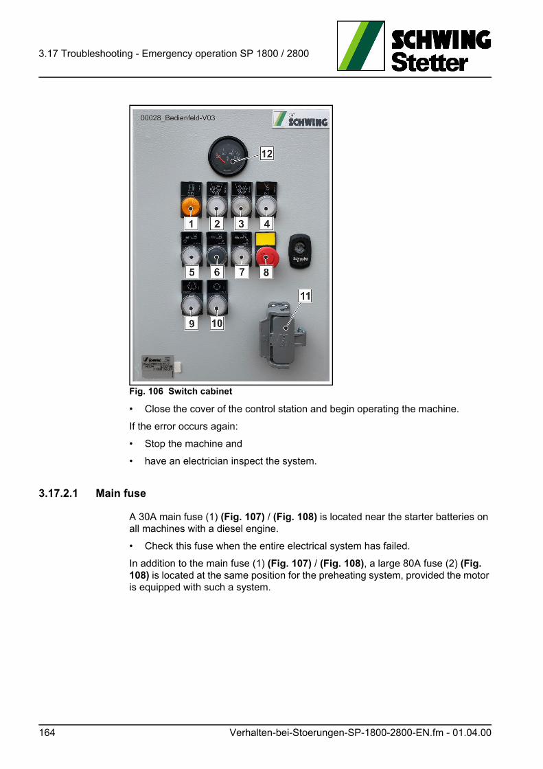
3.17 Troubleshooting - Emergency operation SP 1800 / 2800
Fig. 106 Switch cabinet
• Close the cover of the control station and begin operating the machine.
If the error occurs again:
• Stop the machine and
• have an electrician inspect the system.
3.17.2.1 Main fuse
A 30A main fuse (1) (Fig. 107) / (Fig. 108) is located near the starter batteries on all machines with a diesel engine.
• Check this fuse when the entire electrical system has failed.
In addition to the main fuse (1) (Fig. 107) / (Fig. 108), a large 80A fuse (2) (Fig. 108) is located at the same position for the preheating system, provided the motor is equipped with such a system.
164 Verhalten-bei-Stoerungen-SP-1800-2800-EN.fm - 01.04.00
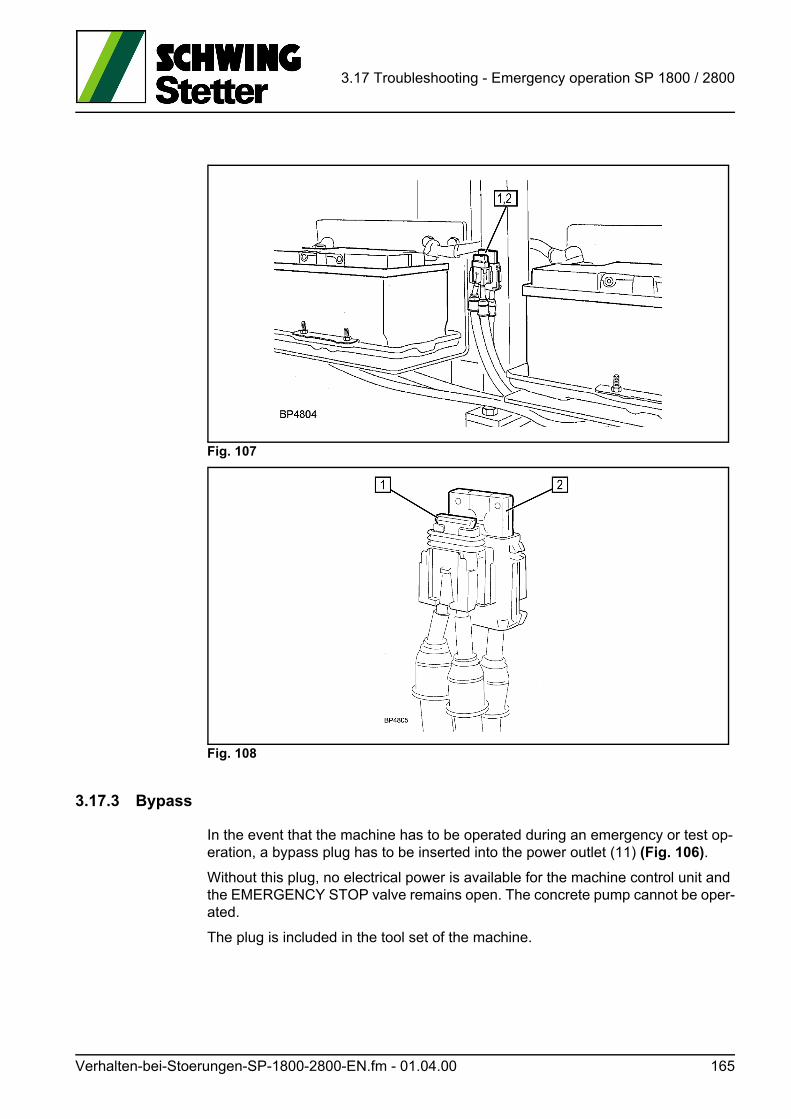
3.17 Troubleshooting - Emergency operation SP 1800 / 2800
Fig. 107
Fig. 108
3.17.3 Bypass
In the event that the machine has to be operated during an emergency or test op-eration, a bypass plug has to be inserted into the power outlet (11) (Fig. 106).
Without this plug, no electrical power is available for the machine control unit and the EMERGENCY STOP valve remains open. The concrete pump cannot be oper-ated.
The plug is included in the tool set of the machine.
Verhalten-bei-Stoerungen-SP-1800-2800-EN.fm - 01.04.00 165
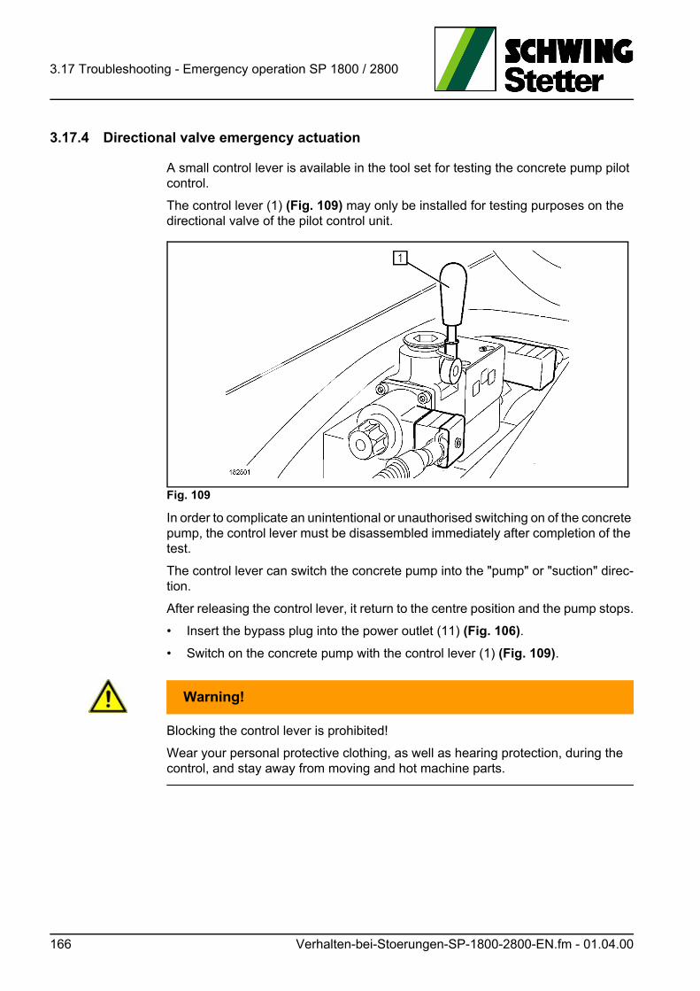
3.17 Troubleshooting - Emergency operation SP 1800 / 2800
3.17.4 Directional valve emergency actuation
A small control lever is available in the tool set for testing the concrete pump pilot control.
The control lever (1) (Fig. 109) may only be installed for testing purposes on the directional valve of the pilot control unit.
Fig. 109
In order to complicate an unintentional or unauthorised switching on of the concrete pump, the control lever must be disassembled immediately after completion of the test.
The control lever can switch the concrete pump into the "pump" or "suction" direc-tion.
After releasing the control lever, it return to the centre position and the pump stops.
• Insert the bypass plug into the power outlet (11) (Fig. 106).
• Switch on the concrete pump with the control lever (1) (Fig. 109).
WARNUNG! Warning!
Blocking the control lever is prohibited!
Wear your personal protective clothing, as well as hearing protection, during the control, and stay away from moving and hot machine parts.
166 Verhalten-bei-Stoerungen-SP-1800-2800-EN.fm - 01.04.00
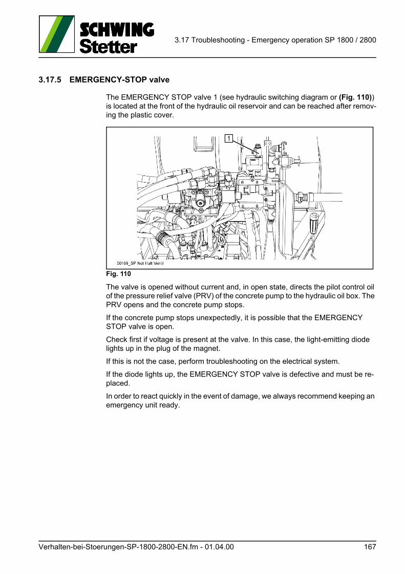
3.17 Troubleshooting - Emergency operation SP 1800 / 2800
3.17.5 EMERGENCY-STOP valve
The EMERGENCY STOP valve 1 (see hydraulic switching diagram or (Fig. 110)) is located at the front of the hydraulic oil reservoir and can be reached after remov-ing the plastic cover.
Fig. 110
The valve is opened without current and, in open state, directs the pilot control oil of the pressure relief valve (PRV) of the concrete pump to the hydraulic oil box. The PRV opens and the concrete pump stops.
If the concrete pump stops unexpectedly, it is possible that the EMERGENCY STOP valve is open.
Check first if voltage is present at the valve. In this case, the light-emitting diode lights up in the plug of the magnet.
If this is not the case, perform troubleshooting on the electrical system.
If the diode lights up, the EMERGENCY STOP valve is defective and must be re-placed.
In order to react quickly in the event of damage, we always recommend keeping an emergency unit ready.
Verhalten-bei-Stoerungen-SP-1800-2800-EN.fm - 01.04.00 167

3.17 Troubleshooting - Emergency operation SP 1800 / 2800
168 Verhalten-bei-Stoerungen-SP-1800-2800-EN.fm - 01.04.00
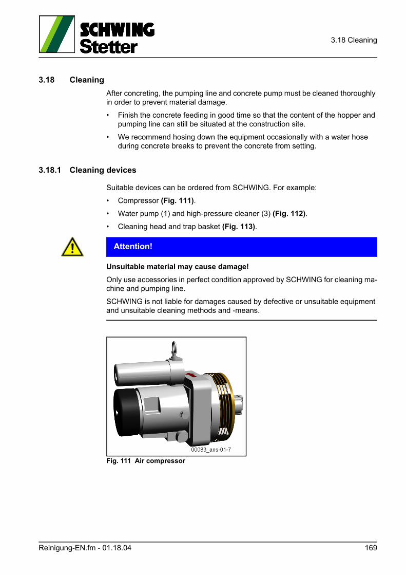
3.18 Cleaning
3.18 Cleaning
After concreting, the pumping line and concrete pump must be cleaned thoroughly in order to prevent material damage.
• Finish the concrete feeding in good time so that the content of the hopper and pumping line can still be situated at the construction site.
• We recommend hosing down the equipment occasionally with a water hose during concrete breaks to prevent the concrete from setting.
3.18.1 Cleaning devices
Suitable devices can be ordered from SCHWING. For example:
• Compressor (Fig. 111).
• Water pump (1) and high-pressure cleaner (3) (Fig. 112).
• Cleaning head and trap basket (Fig. 113).
ACHTUNG! Attention!
Unsuitable material may cause damage!
Only use accessories in perfect condition approved by SCHWING for cleaning ma-chine and pumping line.
SCHWING is not liable for damages caused by defective or unsuitable equipment and unsuitable cleaning methods and -means.
Fig. 111 Air compressor
Reinigung-EN.fm - 01.18.04 169
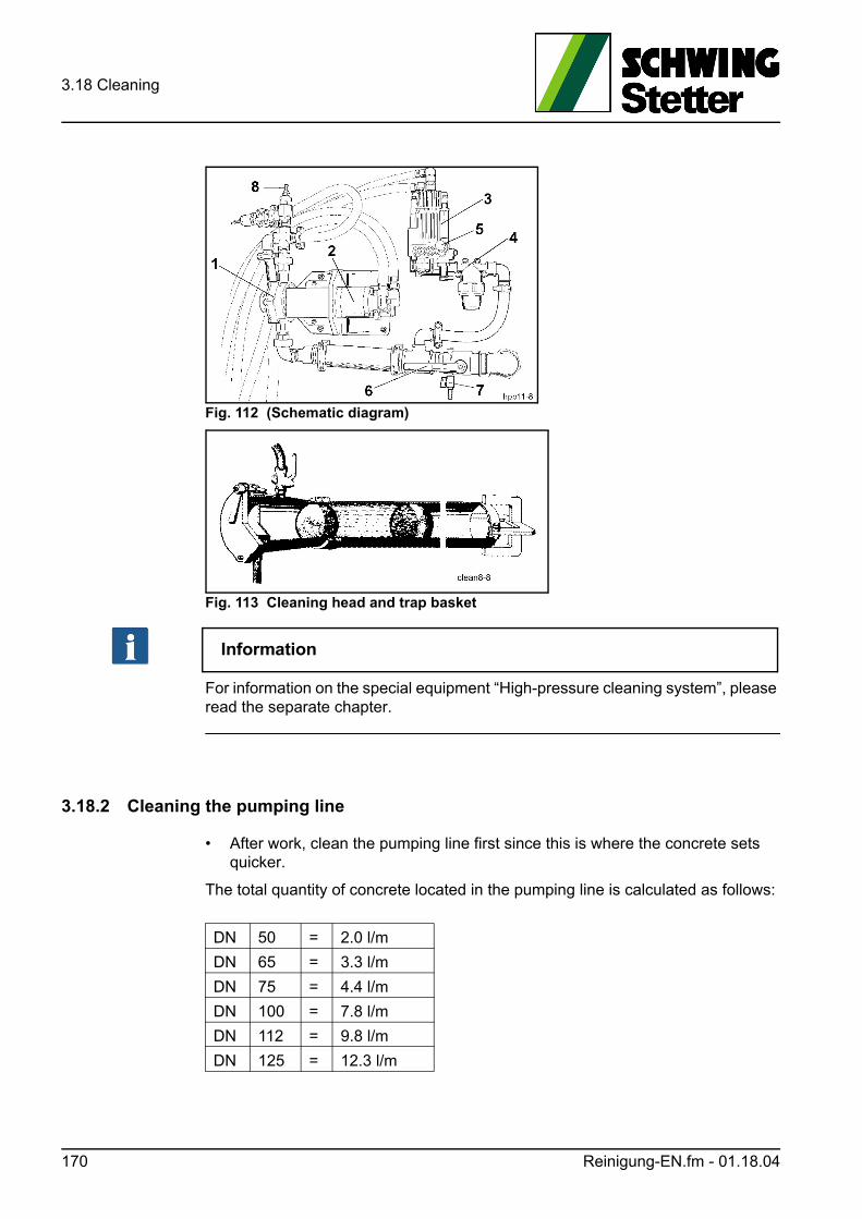
3.18 Cleaning
Fig. 112 (Schematic diagram)
Fig. 113 Cleaning head and trap basket
Information
For information on the special equipment “High-pressure cleaning system”, please read the separate chapter.
3.18.2 Cleaning the pumping line
• After work, clean the pumping line first since this is where the concrete sets quicker.
The total quantity of concrete located in the pumping line is calculated as follows:
DN 50 = 2.0 l/m
DN 65 = 3.3 l/m
DN 75 = 4.4 l/m
DN 100 = 7.8 l/m
DN 112 = 9.8 l/m
DN 125 = 12.3 l/m
170 Reinigung-EN.fm - 01.18.04
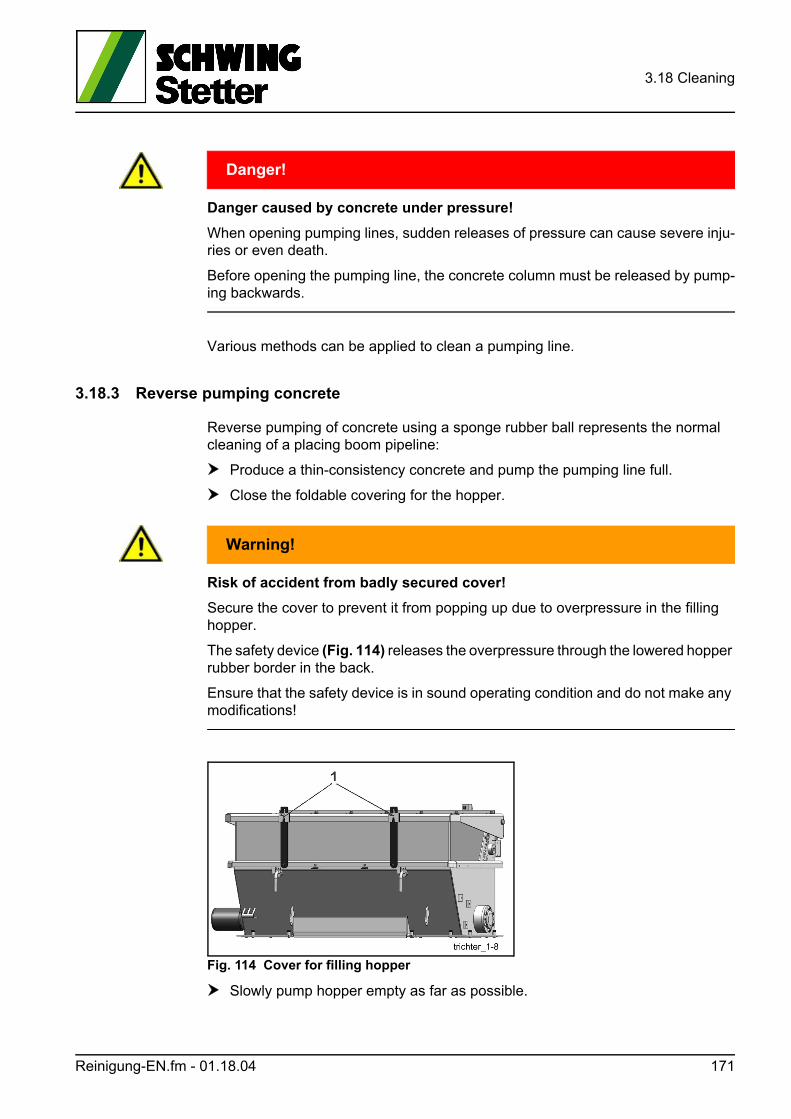
3.18 Cleaning
GEFAHR! Danger!
Danger caused by concrete under pressure!
When opening pumping lines, sudden releases of pressure can cause severe inju-ries or even death.
Before opening the pumping line, the concrete column must be released by pump-ing backwards.
Various methods can be applied to clean a pumping line.
3.18.3 Reverse pumping concrete
Reverse pumping of concrete using a sponge rubber ball represents the normal cleaning of a placing boom pipeline:
Produce a thin-consistency concrete and pump the pumping line full.
Close the foldable covering for the hopper.
WARNUNG! Warning!
Risk of accident from badly secured cover!
Secure the cover to prevent it from popping up due to overpressure in the filling hopper.
The safety device (Fig. 114) releases the overpressure through the lowered hopper rubber border in the back.
Ensure that the safety device is in sound operating condition and do not make any modifications!
Fig. 114 Cover for filling hopper
Slowly pump hopper empty as far as possible.
Reinigung-EN.fm - 01.18.04 171
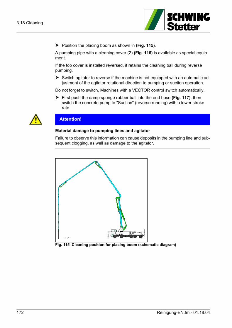
3.18 Cleaning
Position the placing boom as shown in (Fig. 115).
A pumping pipe with a cleaning cover (2) (Fig. 116) is available as special equip-ment.
If the top cover is installed reversed, it retains the cleaning ball during reverse pumping.
Switch agitator to reverse if the machine is not equipped with an automatic ad-justment of the agitator rotational direction to pumping or suction operation.
Do not forget to switch. Machines with a VECTOR control switch automatically.
First push the damp sponge rubber ball into the end hose (Fig. 117), then switch the concrete pump to "Suction" (reverse running) with a lower stroke rate.
ACHTUNG! Attention!
Material damage to pumping lines and agitator
Failure to observe this information can cause deposits in the pumping line and sub-sequent clogging, as well as damage to the agitator.
Fig. 115 Cleaning position for placing boom (schematic diagram)
172 Reinigung-EN.fm - 01.18.04
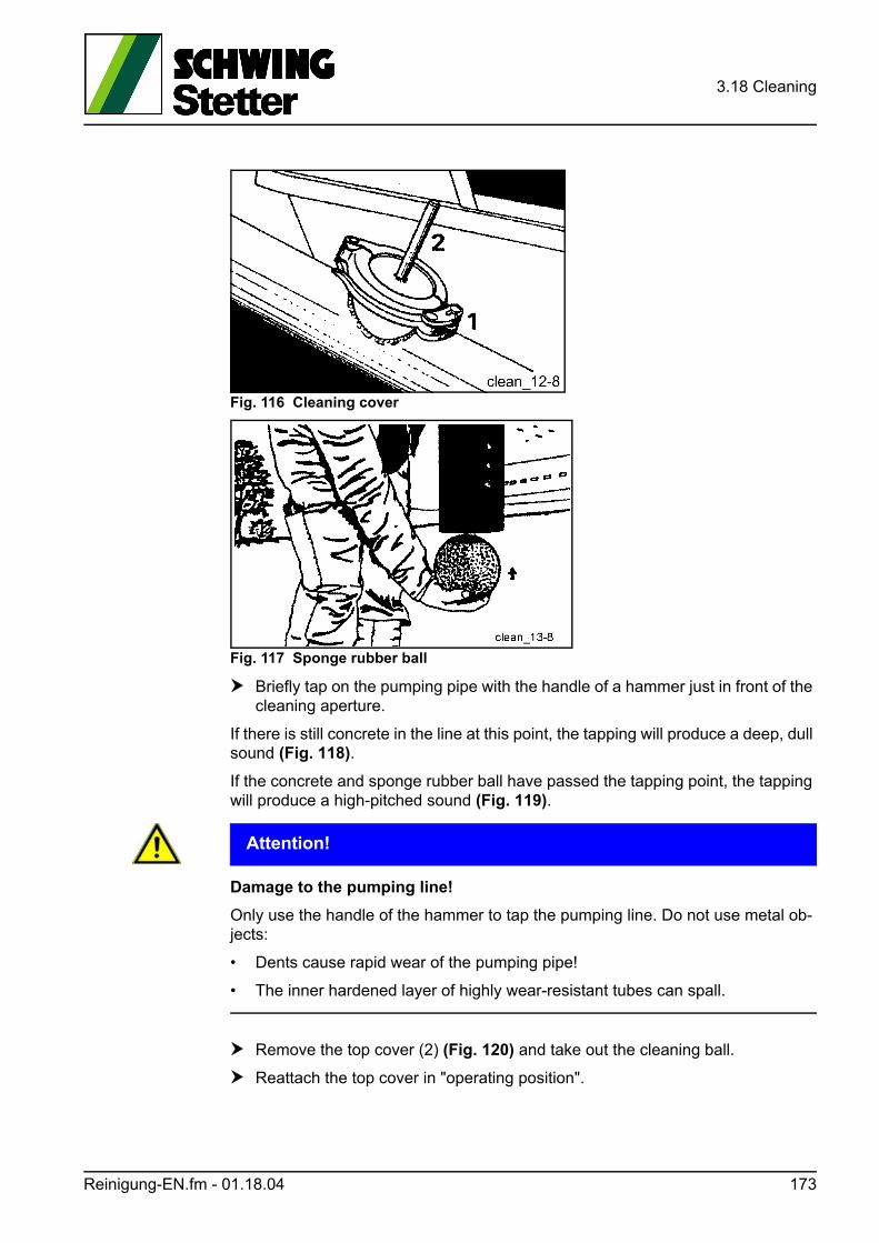
3.18 Cleaning
Fig. 116 Cleaning cover
Fig. 117 Sponge rubber ball
Briefly tap on the pumping pipe with the handle of a hammer just in front of the cleaning aperture.
If there is still concrete in the line at this point, the tapping will produce a deep, dull sound (Fig. 118).
If the concrete and sponge rubber ball have passed the tapping point, the tapping will produce a high-pitched sound (Fig. 119).
ACHTUNG! Attention!
Damage to the pumping line!
Only use the handle of the hammer to tap the pumping line. Do not use metal ob-jects:
• Dents cause rapid wear of the pumping pipe!
• The inner hardened layer of highly wear-resistant tubes can spall.
Remove the top cover (2) (Fig. 120) and take out the cleaning ball.
Reattach the top cover in "operating position".
Reinigung-EN.fm - 01.18.04 173
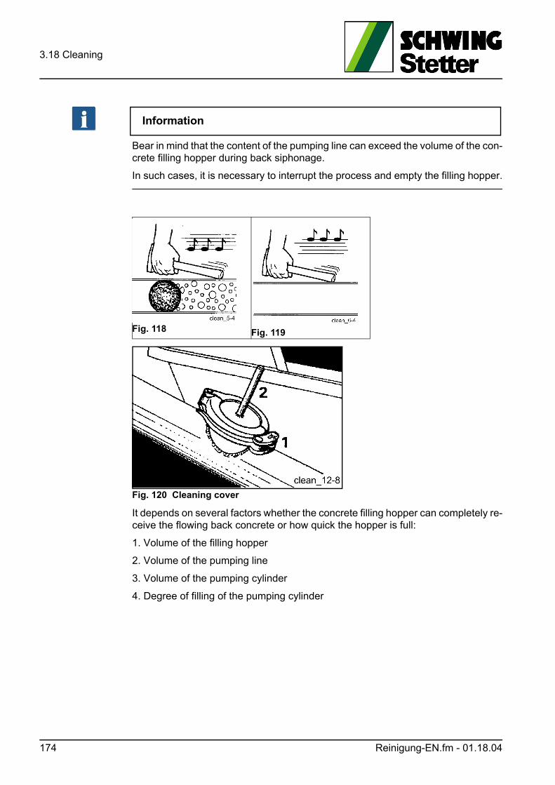
3.18 Cleaning
Information
Bear in mind that the content of the pumping line can exceed the volume of the con-crete filling hopper during back siphonage.
In such cases, it is necessary to interrupt the process and empty the filling hopper.
Fig. 120 Cleaning cover
It depends on several factors whether the concrete filling hopper can completely re-ceive the flowing back concrete or how quick the hopper is full:
1. Volume of the filling hopper
2. Volume of the pumping line
3. Volume of the pumping cylinder
4. Degree of filling of the pumping cylinder
Fig. 118 Fig. 119
174 Reinigung-EN.fm - 01.18.04
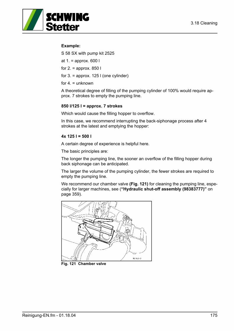
3.18 Cleaning
Example:
S 58 SX with pump kit 2525
at 1. = approx. 600 l
for 2. = approx. 850 l
for 3. = approx. 125 l (one cylinder)
for 4. = unknown
A theoretical degree of filling of the pumping cylinder of 100% would require ap-prox. 7 strokes to empty the pumping line.
850 l/125 l = approx. 7 strokes
Which would cause the filling hopper to overflow.
In this case, we recommend interrupting the back-siphonage process after 4 strokes at the latest and emptying the hopper:
4x 125 l = 500 l
A certain degree of experience is helpful here.
The basic principles are:
The longer the pumping line, the sooner an overflow of the filling hopper during back siphonage can be anticipated.
The larger the volume of the pumping cylinder, the fewer strokes are required to empty the pumping line.
We recommend our chamber valve (Fig. 121) for cleaning the pumping line, espe-cially for larger machines, see (“Hydraulic shut-off assembly (98383777)” on page 359).
Fig. 121 Chamber valve
Reinigung-EN.fm - 01.18.04 175
3.18 Cleaning
3.18.4 Clearing the pumping line with water
This method is ideal for separately laid, long pipelines, vertical lines and lines with a downstream placing boom.
For stiff, rough, fine-grained or sand-poor concretes, this method can also be rec-ommended for the boom pipeline of truck-mounted concrete pumps.
The following is required in addition to a powerful water pump (Fig. 122):
1. Cleaning head with water connection
2. Soft sponge rubber ball
3. Paper plug
The paper plug is made of soaked, double-folded, tightly rolled-up, empty cement bags.
Information
The plug must be completely sealed to prevent the concrete from leaching.
3.18.5 Rinsing the pumping line
Cement residues are removed from the tube walls by rinsing the emptied pumping line.
To do this, press a soft sponge rubber ball about 1 m into the pumping pipe (Fig. 123).
Mount the cleaning head, with a soft sponge rubber ball attached to it, onto the pipeline.
Fill with water between both balls.
Use the water cushion to press both balls through the line, like when blowing out with air, (see “Blowing out the pumping line with compressed air” on page 178). Raise the placing boom if necessary.
ACHTUNG! Attention!
Frost damage!
In case of danger of frost, remove water from the pumping line.
176 Reinigung-EN.fm - 01.18.04
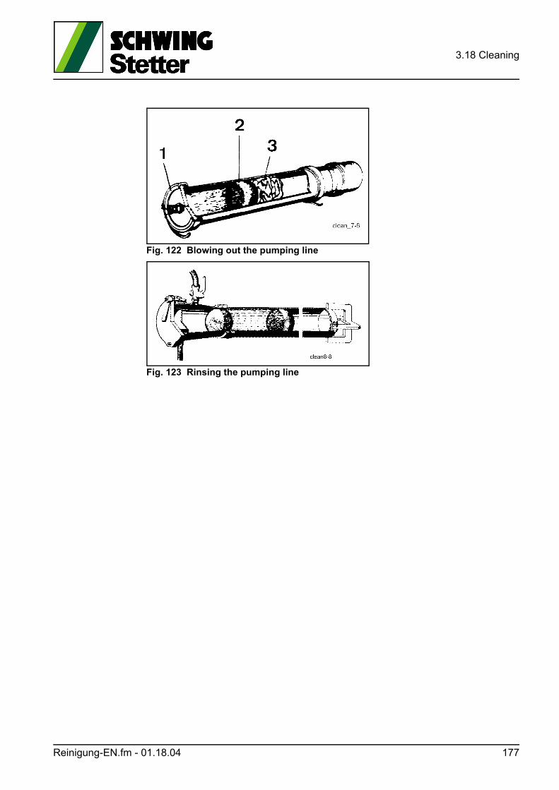
3.18 Cleaning
Fig. 122 Blowing out the pumping line
Fig. 123 Rinsing the pumping line
Reinigung-EN.fm - 01.18.04 177
3.18 Cleaning
3.18.6 Blowing out the pumping line with compressed air
WARNUNG! Warning!
Severe injuries due to compressed air
Severe injuries due to flying material.
Air can become compressed in pumping pipes and be discharged explosively, which can result in severe injuries.
Avoid excessive concentrations of compressed air in pumping pipes.
The following points must be observed when blowing out the pipeline with com-pressed air.
1. The blowing out must be carried out under expert guidance.
2. Elbows or hoses may not be mounted at the end of the pipeline.
3. No-one may remain in the area of the concrete output.
4. Empty and rinse tapered tubes manually. Only blow out pumping lines of the same nominal size.
5. A trap basket must be connected to the concrete outlet (Fig. 124).
6. Set the concrete output high so that the concrete can escape freely.
7. The cleaning head must be equipped with a functioning pressure gauge (2) and a large-dimensioned blow-out cock (3) (Fig. 125).
8. The length of the plug must be such that it seals the pipeline hermetically on the trap basket upon completion of the blowing out.
9. The plug must be sealed in order to prevent the compressed air from penetrat-ing past it into the concrete.
10. Only work on unpressurised pipelines. Open blow-out cock (3) (Fig. 125). Concrete emerging under pressure can injure persons.
11. Individual tubes and short 10 m-long tube strings may not be blown out. High risk of accident caused by recoil due to low mass!
In addition to the prepared paper plug, as described above, a hard sponge rubber ball can be used to blow out tubes.
178 Reinigung-EN.fm - 01.18.04
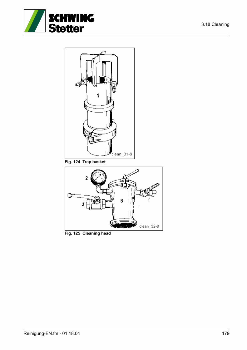
3.18 Cleaning
Fig. 124 Trap basket
Fig. 125 Cleaning head
Reinigung-EN.fm - 01.18.04 179
3.18 Cleaning
3.18.7 Cleaning the concrete pump
WARNUNG! Warning!
Make sure to observe the following points:
• Do not remove the cover grid from the concrete filling hopper or enter the grid.
• Do not reach into the machine while the drive motor is running or the pressure accumulator is charging, and do not hold objects in openings.
An end limit switch stops the concrete pump and the agitator if the grate in the con-crete filling hopper is opened.
This is not an EMERGENCY STOP function!
The interrupted functions restart after closing the grid.
GEFAHR! Danger!
Danger to life by electric shock!
• Do not direct water jets or the jet of a pressure cleaner towards the electrical components of the machine.
3.18.8 Securing the machine
Remove the remote control cable.
Connect the radio remote control transmitter.
Use the local control.
WARNUNG! Warning!
Severe injuries can be caused if the machine is left unattended!
If the machine has to be switched on for cleaning, the machinist is responsible that no unauthorised persons come near the open gate valve housing.
3.18.9 Interior cleaning
Have a drip pan ready for residual concrete before beginning with the cleaning.
Remove the tapered tube from the outlet on the stationary concrete pump or re-move the outlet from the boom on the truck-mounted concrete pump by pivoting it to the side and securing it with the supplied wedge (2) (Fig. 127).
Start up the concrete pump at the lowest stroke rate, in order to pump any re-sidual concrete out of the hopper.
180 Reinigung-EN.fm - 01.18.04
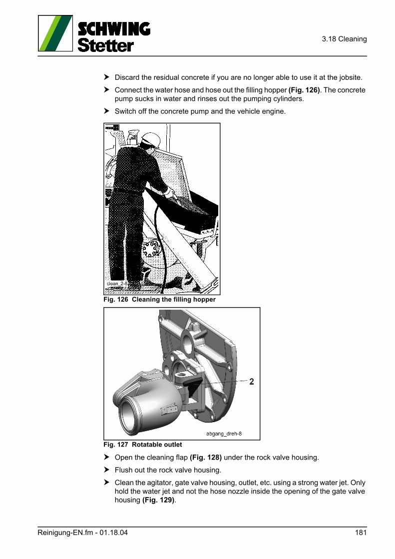
3.18 Cleaning
Discard the residual concrete if you are no longer able to use it at the jobsite.
Connect the water hose and hose out the filling hopper (Fig. 126). The concrete pump sucks in water and rinses out the pumping cylinders.
Switch off the concrete pump and the vehicle engine.
Fig. 126 Cleaning the filling hopper
Fig. 127 Rotatable outlet
Open the cleaning flap (Fig. 128) under the rock valve housing.
Flush out the rock valve housing.
Clean the agitator, gate valve housing, outlet, etc. using a strong water jet. Only hold the water jet and not the hose nozzle inside the opening of the gate valve housing (Fig. 129).
Reinigung-EN.fm - 01.18.04 181
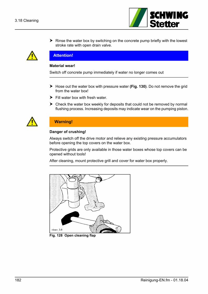
3.18 Cleaning
Rinse the water box by switching on the concrete pump briefly with the lowest stroke rate with open drain valve.
ACHTUNG! Attention!
Material wear!
Switch off concrete pump immediately if water no longer comes out
Hose out the water box with pressure water (Fig. 130). Do not remove the grid from the water box!
Fill water box with fresh water.
Check the water box weekly for deposits that could not be removed by normal flushing process. Increasing deposits may indicate wear on the pumping piston.
WARNUNG! Warning!
Danger of crushing!
Always switch off the drive motor and relieve any existing pressure accumulators before opening the top covers on the water box.
Protective grids are only available in those water boxes whose top covers can be opened without tools!
After cleaning, mount protective grill and cover for water box properly.
Fig. 128 Open cleaning flap
182 Reinigung-EN.fm - 01.18.04
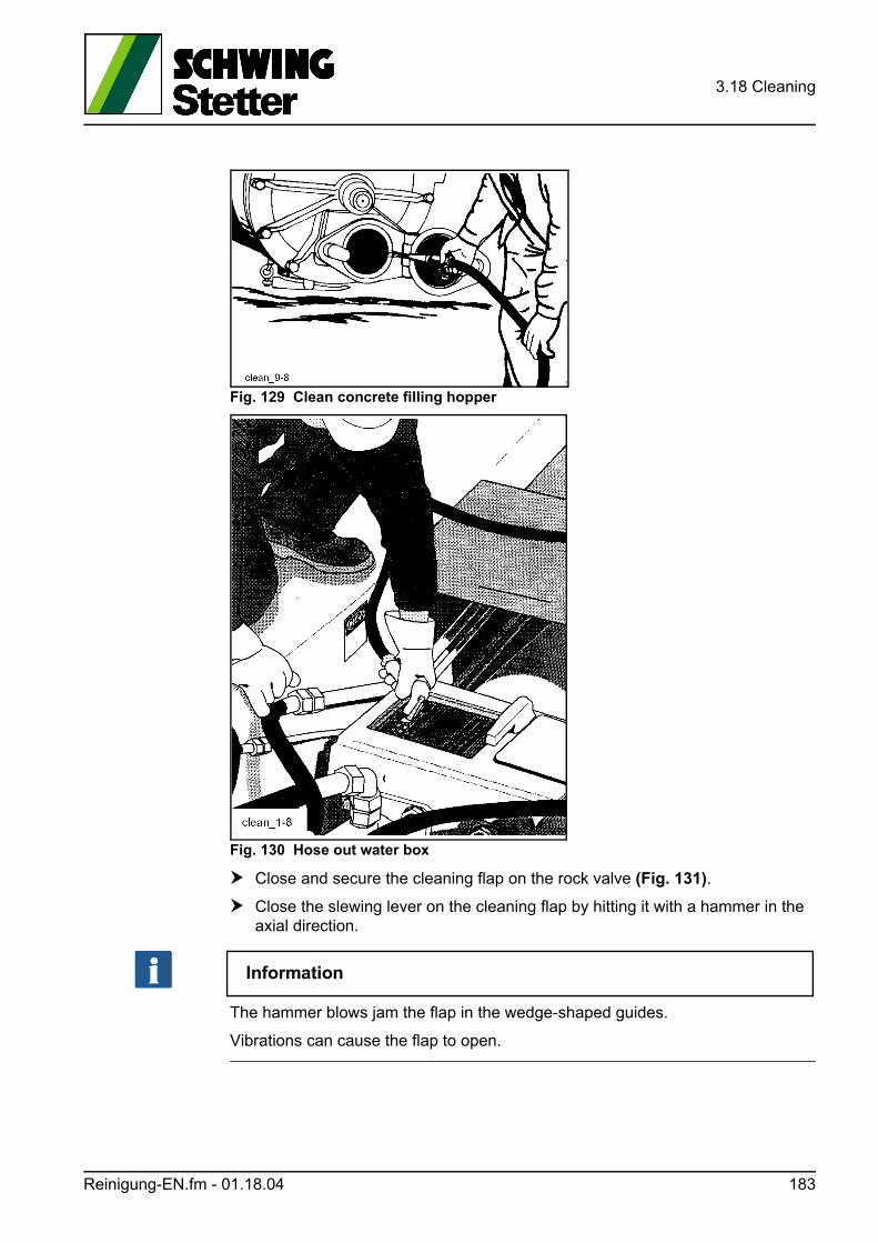
3.18 Cleaning
Fig. 129 Clean concrete filling hopper
Fig. 130 Hose out water box
Close and secure the cleaning flap on the rock valve (Fig. 131).
Close the slewing lever on the cleaning flap by hitting it with a hammer in the axial direction.
Information
The hammer blows jam the flap in the wedge-shaped guides.
Vibrations can cause the flap to open.
Reinigung-EN.fm - 01.18.04 183
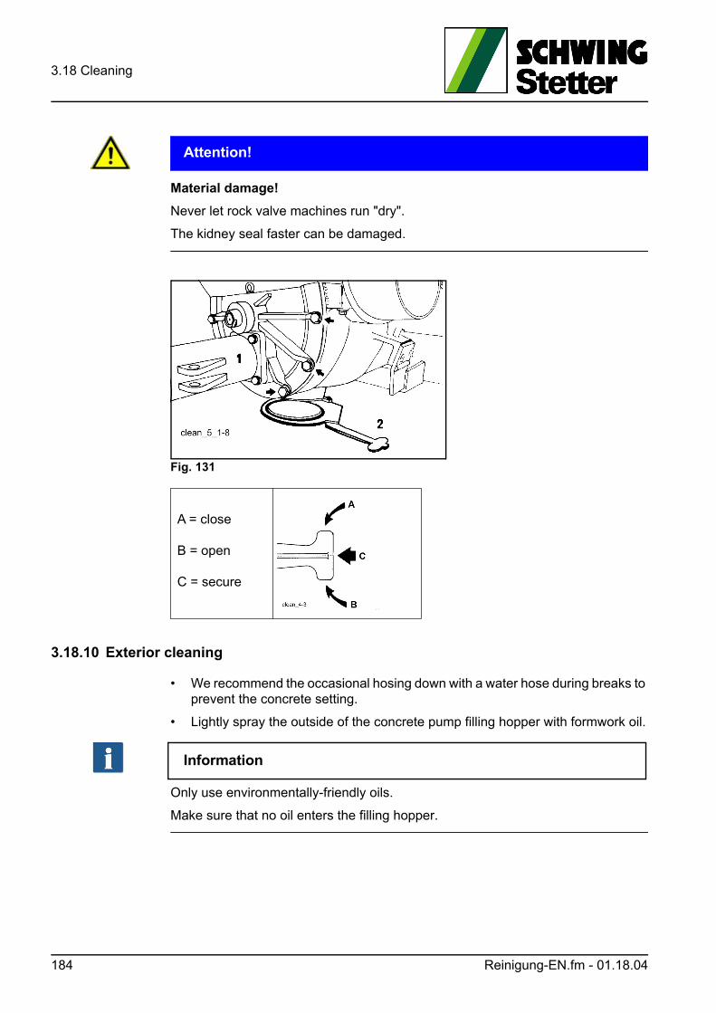
3.18 Cleaning
ACHTUNG! Attention!
Material damage!
Never let rock valve machines run "dry".
The kidney seal faster can be damaged.
Fig. 131
3.18.10 Exterior cleaning
• We recommend the occasional hosing down with a water hose during breaks to prevent the concrete setting.
• Lightly spray the outside of the concrete pump filling hopper with formwork oil.
Information
Only use environmentally-friendly oils.
Make sure that no oil enters the filling hopper.
A = close
B = open
C = secure
184 Reinigung-EN.fm - 01.18.04
3.18 Cleaning
3.18.11 Using high-pressure cleaners (HP cleaners)
WARNUNG! Warning!
Poor preparation can cause accidents!
Observe the operating instructions of the high-pressure cleaner system, and wear the appropriate personal protective covering.
Information
New paints are only properly dry after approx. 3 months.
During this time, do not clean the machine with an HP cleaner.This also applies to repainted sub-areas.
Newly painted surfaces may only be cleaned with a spray hose and cold water dur-ing the first 3 months. Use a soft brush, if necessary.
No HP cleaner should be used in areas with mechanical paint damage, because this can cause painted areas to separate even more.
Damaged painted surfaces should be repaired as soon as possible and in a pro-fessional manner.
During subsequent use of the HP cleaner, please observe:
• Maximum permissible water temperature 60 °C.
• Do not use additives.
• Maximum permissible water pressure 160 bar.
• Minimum permissible spraying distance 30 cm.
ACHTUNG! Attention!
Damages caused by strong water jet!
• If the HP cleaner used generates a higher water pressure, the spraying distance must be increased accordingly.
Reinigung-EN.fm - 01.18.04 185
3.18 Cleaning
3.18.12 Using cleaning agents
GEFAHR! Danger!
Fire hazard!
Do not use highly flammable agents.
• Do not use aggressive cleaning agents. They can corrode different materials (e.g. rubber) and painted surfaces.
• Commercially available paint cleaner and care products can be used, provided they do not exceed a pH value of 9 or fall below a pH value of 4.
Information
Ask the manufacturer of the cleaning agent to confirm its suitability.
Observe his directives on the application and health protection.
Always rinse off the cleaning agents thoroughly with clean water. Do not leave puddles.
3.18.13 After cleaning
Lubricate all lubrication points after cleaning.
We recommend spraying the dry machine with a wax-based preservative for pro-tection against corrosion.
3.18.14 Water box flushing (special equipment)
Our truck-mounted concrete pumps can be equipped with a pressure flush valve for the water box as special equipment.
With this device, the usual manual cleaning of the water box is omitted to a large extent.
Four spraying nozzles in the top cover of the water box rinse the inside of the water box and piston rods of the differential cylinder.
Application:
Open the drain cock (25) (Fig. 132) on the water box at the rear of the machine.
Start the water pump and route pressurised water into the spraying nozzles (3) (Fig. 133) of the water box by switching the corresponding ball valves (11) (Fig. 132) at the rear of the machine and (2) (Fig. 133).
Start the concrete pump at a lower stroke rate.
186 Reinigung-EN.fm - 01.18.04
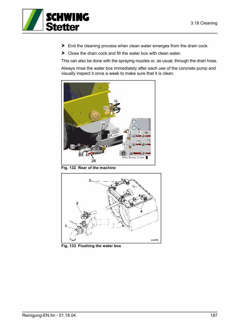
3.18 Cleaning
End the cleaning process when clean water emerges from the drain cock.
Close the drain cock and fill the water box with clean water.
This can also be done with the spraying nozzles or, as usual, through the drain hose.
Always rinse the water box immediately after each use of the concrete pump and visually inspect it once a week to make sure that it is clean.
Fig. 132 Rear of the machine
Fig. 133 Flushing the water box
Reinigung-EN.fm - 01.18.04 187

3.18 Cleaning
188 Reinigung-EN.fm - 01.18.04
3.19 Hazard prevention on the concrete filling hopper
3.19 Hazard prevention on the concrete filling hopper
GEFAHR! Danger!
Danger of death due to exposed agitator!
Danger of death as a result of being crushed by or pulled into the agitator!
Disassembled or open hopper grates, as well as defective or manipulated end limit switches, can cause serious injuries and even death.
The following actions are prohibited on the agitator during operation:
• Reaching through the hopper grate.
• Passing items (e.g. water hose, rod, etc.) through the hopper grate.
3.19.1 Hopper grate
The hopper grate in the concrete filling hopper is coupled to an end limit switch.
The end limit switch stops the rock valve and agitator when the hopper grate is opened.
WARNUNG! Warning!
Risk of serious injury due to defective end limit switch!
If the agitator does not stop automatically when lifted, there is a risk of serious injury and even death.
The end limit switch has to be inspected daily and replaced in the event of a defect.
Arrangement and design of the hopper grate according to EN 12001.
Clean the concrete filling hopper with a strong water jet.
The water jet should be directed onto the area to be cleaned, do not pass the hose nozzle through the hopper grate.
Before removing any fixed concrete residues with the appropriate tools:
• Stop the machine.
• Switch off the drive motor and prevent it from starting up.
• Discharge the pressure accumulator, if applicable.
Gefahrenabwehr-am-Trichter-EN.fm - 01.00.01 189
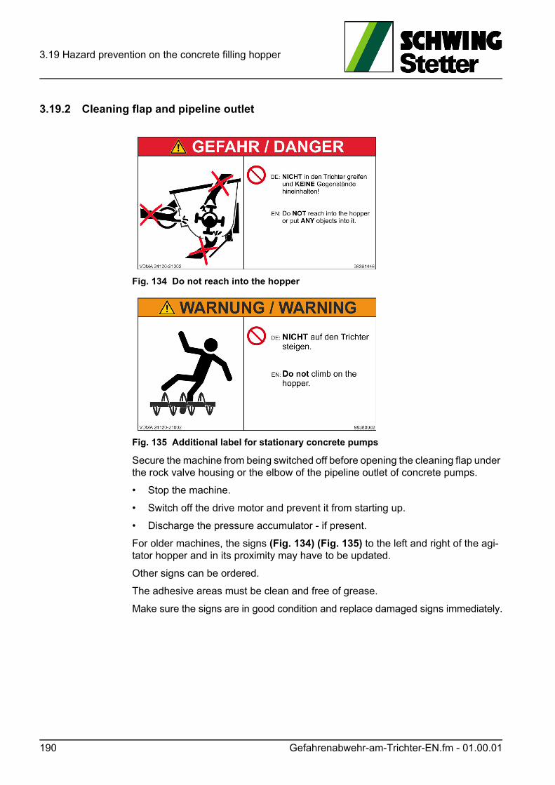
3.19 Hazard prevention on the concrete filling hopper
3.19.2 Cleaning flap and pipeline outlet
Fig. 134 Do not reach into the hopper
Fig. 135 Additional label for stationary concrete pumps
Secure the machine from being switched off before opening the cleaning flap under the rock valve housing or the elbow of the pipeline outlet of concrete pumps.
• Stop the machine.
• Switch off the drive motor and prevent it from starting up.
• Discharge the pressure accumulator - if present.
For older machines, the signs (Fig. 134) (Fig. 135) to the left and right of the agi-tator hopper and in its proximity may have to be updated.
Other signs can be ordered.
The adhesive areas must be clean and free of grease.
Make sure the signs are in good condition and replace damaged signs immediately.
190 Gefahrenabwehr-am-Trichter-EN.fm - 01.00.01
3.20 Establishing transport readiness
3.20 Establishing transport readiness
WARNUNG! Warning!
Checking safety components!
The operator has to carry out an expert inspection prior to each first commission, after any kind of changes to the support equipment and at least once a year accord-ing to manufacturer's instructions.
These inspections should be documented in a suitable form.
The operator should check the support equipment for damages and wear prior to each use. The connection and safety parts should be checked in particular for tight-ness and functionality.
VORSICHT! Caution!
Danger of crushing!
When lowering the machine, ensure that no unauthorised persons are in the vicinity of the machine and no one will be crushed by the machine or machine parts.
Perform the following, general tasks:
Clean the machine and switch off the concrete pump, auxiliary drive and drive motor.
Disconnect the remote control cable from the machine.
Mount the wheels, if necessary.
Secure the machine using wheel wedges.
Lay a suitable support pad (e.g. item no.: 1095646) under the supporting dish of the crank support (Fig. 138).
Proceed with the subsequent steps depending on the type of outrigger:
3.20.1 Mechanical outrigger SP 1800
Lower the crank (3) (Fig. 136) by rotating the support dish.
Lift the front of the machine slightly until the front supports (1) (Fig. 137) are un-burdened.
Insert the interior tubes of the front supports and secure them with socket pins and split pins.
Transportbereitschaft-herstellen-EN.fm - 01.01.00 191
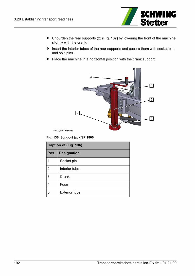
3.20 Establishing transport readiness
Unburden the rear supports (2) (Fig. 137) by lowering the front of the machine slightly with the crank.
Insert the interior tubes of the rear supports and secure them with socket pins and split pins.
Place the machine in a horizontal position with the crank support.
Fig. 136 Support jack SP 1800
Caption of (Fig. 136)
Pos. Designation
1 Socket pin
2 Interior tube
3 Crank
4 Fuse
5 Exterior tube
192 Transportbereitschaft-herstellen-EN.fm - 01.01.00
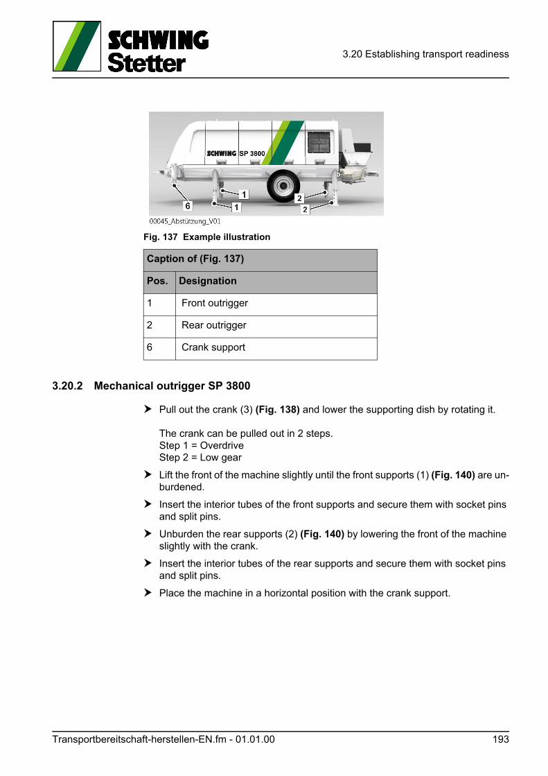
3.20 Establishing transport readiness
Fig. 137 Example illustration
3.20.2 Mechanical outrigger SP 3800
Pull out the crank (3) (Fig. 138) and lower the supporting dish by rotating it.
The crank can be pulled out in 2 steps.Step 1 = OverdriveStep 2 = Low gear
Lift the front of the machine slightly until the front supports (1) (Fig. 140) are un-burdened.
Insert the interior tubes of the front supports and secure them with socket pins and split pins.
Unburden the rear supports (2) (Fig. 140) by lowering the front of the machine slightly with the crank.
Insert the interior tubes of the rear supports and secure them with socket pins and split pins.
Place the machine in a horizontal position with the crank support.
Caption of (Fig. 137)
Pos. Designation
1 Front outrigger
2 Rear outrigger
6 Crank support
Transportbereitschaft-herstellen-EN.fm - 01.01.00 193
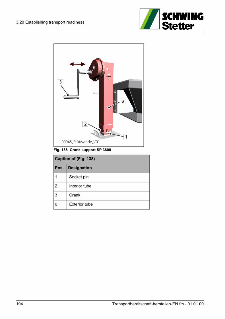
3.20 Establishing transport readiness
Fig. 138 Crank support SP 3800
Caption of (Fig. 138)
Pos. Designation
1 Socket pin
2 Interior tube
3 Crank
6 Exterior tube
194 Transportbereitschaft-herstellen-EN.fm - 01.01.00
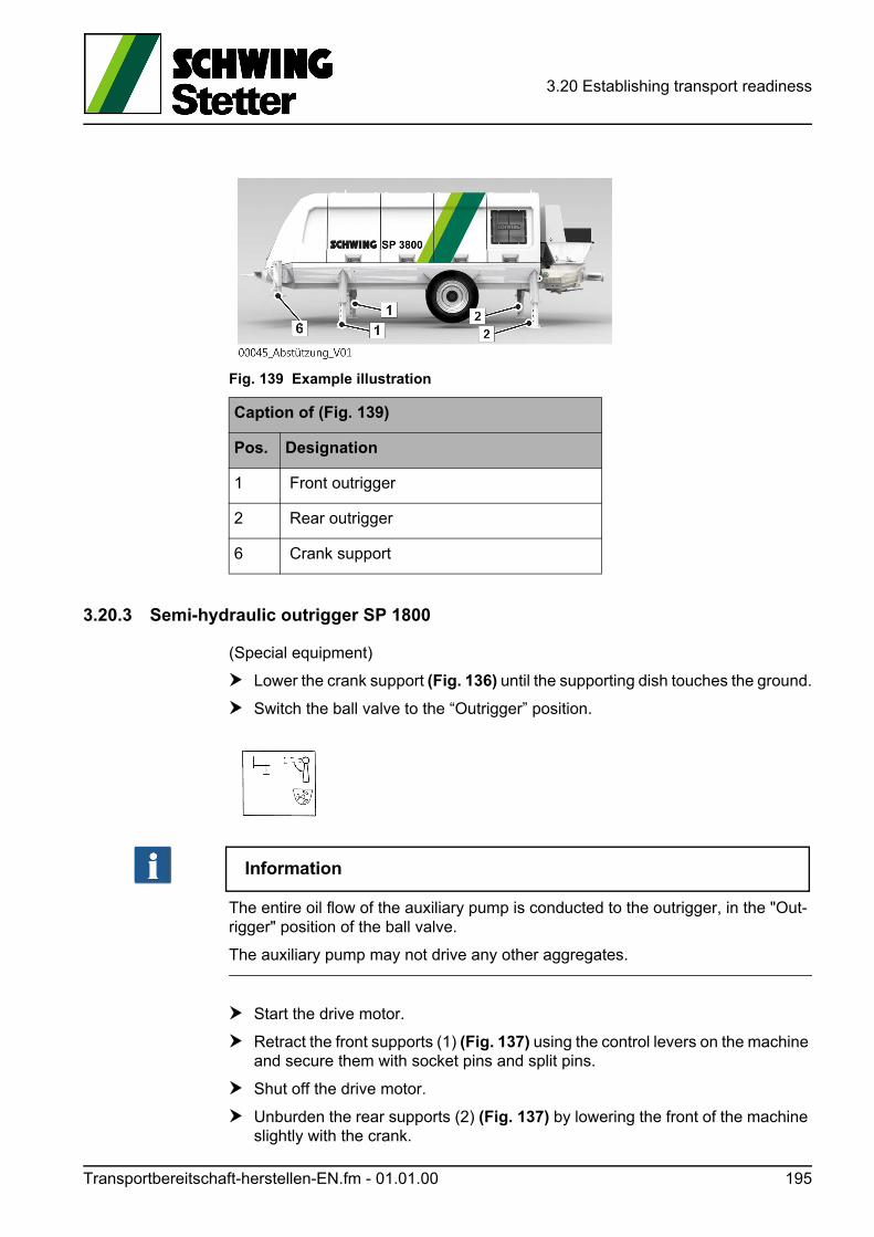
3.20 Establishing transport readiness
Fig. 139 Example illustration
3.20.3 Semi-hydraulic outrigger SP 1800
(Special equipment)
Lower the crank support (Fig. 136) until the supporting dish touches the ground.
Switch the ball valve to the “Outrigger” position.
Information
The entire oil flow of the auxiliary pump is conducted to the outrigger, in the "Out-rigger" position of the ball valve.
The auxiliary pump may not drive any other aggregates.
Start the drive motor.
Retract the front supports (1) (Fig. 137) using the control levers on the machine and secure them with socket pins and split pins.
Shut off the drive motor.
Unburden the rear supports (2) (Fig. 137) by lowering the front of the machine slightly with the crank.
Caption of (Fig. 139)
Pos. Designation
1 Front outrigger
2 Rear outrigger
6 Crank support
Transportbereitschaft-herstellen-EN.fm - 01.01.00 195
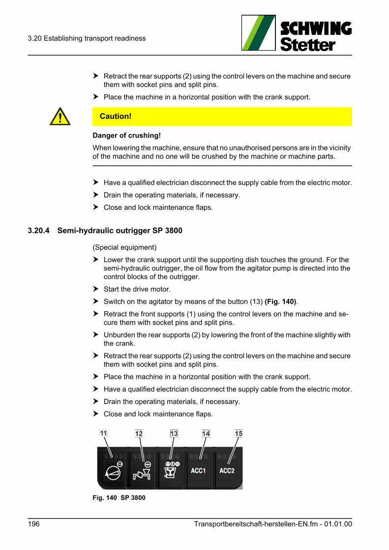
3.20 Establishing transport readiness
Retract the rear supports (2) using the control levers on the machine and secure them with socket pins and split pins.
Place the machine in a horizontal position with the crank support.
VORSICHT! Caution!
Danger of crushing!
When lowering the machine, ensure that no unauthorised persons are in the vicinity of the machine and no one will be crushed by the machine or machine parts.
Have a qualified electrician disconnect the supply cable from the electric motor.
Drain the operating materials, if necessary.
Close and lock maintenance flaps.
3.20.4 Semi-hydraulic outrigger SP 3800
(Special equipment)
Lower the crank support until the supporting dish touches the ground. For the semi-hydraulic outrigger, the oil flow from the agitator pump is directed into the control blocks of the outrigger.
Start the drive motor.
Switch on the agitator by means of the button (13) (Fig. 140).
Retract the front supports (1) using the control levers on the machine and se-cure them with socket pins and split pins.
Unburden the rear supports (2) by lowering the front of the machine slightly with the crank.
Retract the rear supports (2) using the control levers on the machine and secure them with socket pins and split pins.
Place the machine in a horizontal position with the crank support.
Have a qualified electrician disconnect the supply cable from the electric motor.
Drain the operating materials, if necessary.
Close and lock maintenance flaps.
Fig. 140 SP 3800
196 Transportbereitschaft-herstellen-EN.fm - 01.01.00
3.20 Establishing transport readiness
3.20.5 Coupling SP 1800
VORSICHT! Caution!
Danger of crushing!
No one may remain between concrete pump and towing vehicle during coupling.
Set the height of the draw bar using the crank support and couple the machine to the towing vehicle.
Slightly retract the interior tube of the crank support with the crank.
Remove the socket pin and insert the interior tube of the crank support.
Secure the interior tube with the socket pin and spit pins.
Remove the crank prior to driving operation.
3.20.6 Coupling SP 3800
VORSICHT! Caution!
Danger of crushing!
No one may remain between concrete pump and towing vehicle during coupling.
Set the height of the draw bar using the crank support and couple the machine to the towing vehicle.
The crank can be pulled out in 2 steps.Step 1 = OverdriveStep 2 = Low gear
Slightly retract the interior tube of the crank support with the crank.
Remove the socket pin and insert the interior tube of the crank support.
Secure the interior tube with the socket pin and spit pins.
Remove the crank prior to driving operation.
Transportbereitschaft-herstellen-EN.fm - 01.01.00 197
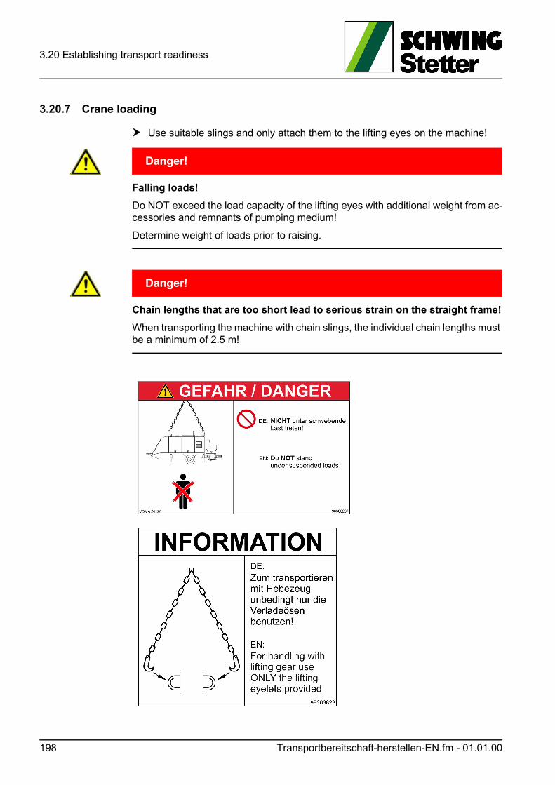
3.20 Establishing transport readiness
3.20.7 Crane loading
Use suitable slings and only attach them to the lifting eyes on the machine!
GEFAHR! Danger!
Falling loads!
Do NOT exceed the load capacity of the lifting eyes with additional weight from ac-cessories and remnants of pumping medium!
Determine weight of loads prior to raising.
GEFAHR! Danger!
Chain lengths that are too short lead to serious strain on the straight frame!
When transporting the machine with chain slings, the individual chain lengths must be a minimum of 2.5 m!
198 Transportbereitschaft-herstellen-EN.fm - 01.01.00
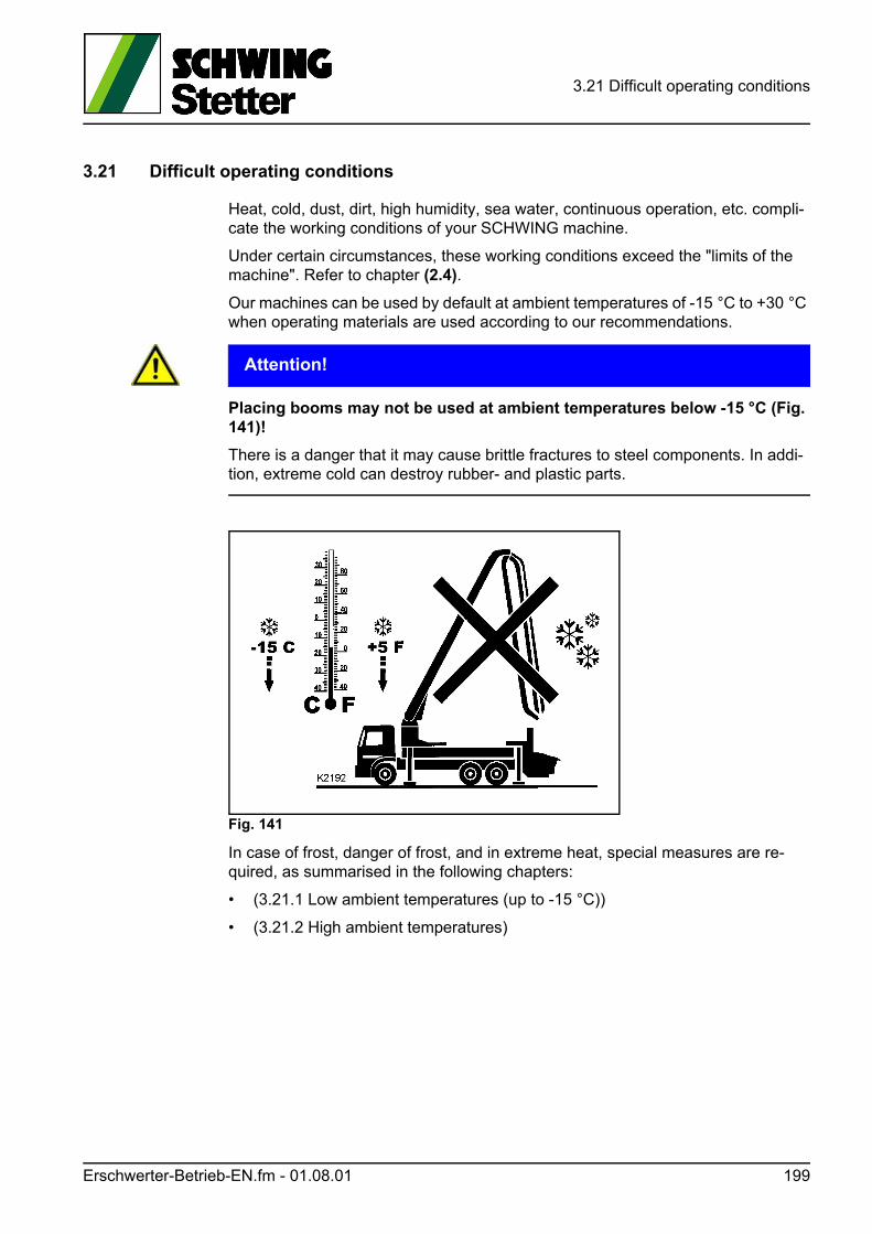
3.21 Difficult operating conditions
3.21 Difficult operating conditions
Heat, cold, dust, dirt, high humidity, sea water, continuous operation, etc. compli-cate the working conditions of your SCHWING machine.
Under certain circumstances, these working conditions exceed the "limits of the machine". Refer to chapter (2.4).
Our machines can be used by default at ambient temperatures of -15 °C to +30 °C when operating materials are used according to our recommendations.
ACHTUNG! Attention!
Placing booms may not be used at ambient temperatures below -15 °C (Fig. 141)!
There is a danger that it may cause brittle fractures to steel components. In addi-tion, extreme cold can destroy rubber- and plastic parts.
Fig. 141
In case of frost, danger of frost, and in extreme heat, special measures are re-quired, as summarised in the following chapters:
• (3.21.1 Low ambient temperatures (up to -15 °C))
• (3.21.2 High ambient temperatures)
Erschwerter-Betrieb-EN.fm - 01.08.01 199
3.21 Difficult operating conditions
3.21.1 Low ambient temperatures (up to -15 °C)
3.21.1.1 General
• Move the machine into an enclosed building overnight, if possible.
3.21.1.2 Vehicle motor and integrated motor
Observe the manufacturer's operating instructions. Experience has shown that at least the following measures are required:
• Change oil and filter, unless a suitable multi-purpose oil is being used
• Check frost protection
• Adapt frost protector for air system
• Refuel with winter diesel fuel
• Ensure that the electrical system is in good condition, see (3.21.1.9).
3.21.1.3 Water system
ACHTUNG! Attention!
Danger of ice and frost damage!!
Overflowing water freezes and can cause serious material damage.
Do not switch on frozen aggregates (e.g. water pump).
Do not heat with a flame or pour hot liquid over them.
Defrost machine fluids in an enclosed building.
• Fill the water into the water box and water case immediately before the first as-signment.
A layer of ice must not form on the inside walls of the water box and pumping cyl-inders! Seals and pumping pistons will be destroyed.
Possibly fill with warmed (not hot!) water.
The water in the water box does not freeze as long as it is moving and all aggre-gates produce sufficient heat.
It is possible to add antifreeze to the water in the water case of the truck-mounted concrete pump.
200 Erschwerter-Betrieb-EN.fm - 01.08.01
3.21 Difficult operating conditions
Information
Water offset with antifreeze may not come into contact with concrete!
• After the assignment, drain the entire water system (water pipes and pump, wa-ter box, water case). Switch on the concrete pump briefly to remove the water from the pumping cylinders.
3.21.1.4 Hydraulic system
SCHWING recommends appropriate hydraulic fluids for different climates and ap-plications, see (“Recommended lubricants and fuels” on page 227).
The multi-purpose hydraulic oil filled in at the Herne factory can remain in the sys-tem, as long as the starting temperature does not drop below -10 °C.
Should work be performed at temperatures ranging between -10 °C and -15 °C, switching over to winter oil (VG 32) is required.
Otherwise, the great oil viscosity can cause a risk of damage during a cold start. The hydraulic pumps suck in air (oil foams) and will be damaged.
When changing the oil, also replace the filters.
Make sure that the optimum operating viscosity (16 to 36 mm²/s) is also at an oil temperature between approx. 35 and 65 °C for hydraulic oil with viscosity class* VG 32.
Information
The system may only be fully loaded in the area of the optimum operating viscosity.
However, the highest permissible temperature for VG 32 is below that of VG 46 or VG 68.
See diagram in (Table 1 Comparison of viscosity classes).
a) Cold-start limit in °C
b) Oil temperature in °C
c) Viscosity in mm²/s
d) Operating temperature and viscosity
* Viscosity = Resistance to flow
Erschwerter-Betrieb-EN.fm - 01.08.01 201
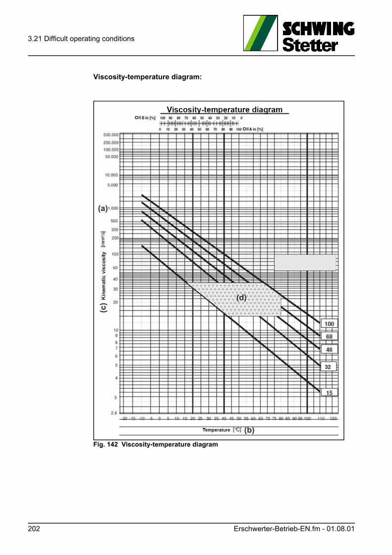
3.21 Difficult operating conditions
Viscosity-temperature diagram:
Fig. 142 Viscosity-temperature diagram
202 Erschwerter-Betrieb-EN.fm - 01.08.01
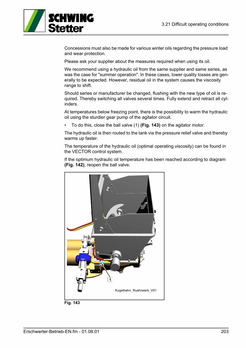
3.21 Difficult operating conditions
Concessions must also be made for various winter oils regarding the pressure load and wear protection.
Please ask your supplier about the measures required when using its oil.
We recommend using a hydraulic oil from the same supplier and same series, as was the case for "summer operation". In these cases, lower quality losses are gen-erally to be expected. However, residual oil in the system causes the viscosity range to shift.
Should series or manufacturer be changed, flushing with the new type of oil is re-quired. Thereby switching all valves several times. Fully extend and retract all cyl-inders.
At temperatures below freezing point, there is the possibility to warm the hydraulic oil using the sturdier gear pump of the agitator circuit.
• To do this, close the ball valve (1) (Fig. 143) on the agitator motor.
The hydraulic oil is then routed to the tank via the pressure relief valve and thereby warms up faster.
The temperature of the hydraulic oil (optimal operating viscosity) can be found in the VECTOR control system.
If the optimum hydraulic oil temperature has been reached according to diagram (Fig. 142), reopen the ball valve.
Fig. 143
Erschwerter-Betrieb-EN.fm - 01.08.01 203
3.21 Difficult operating conditions
3.21.1.5 Air system
Due to their construction, piston compressors may not be started up at ambient temperatures below +1 °C (risk of damage caused by frozen condensate).
Rotation compressors can be used at up to -15 °C, with appropriate maintenance.
Since the vehicle air system supplies the electro-pneumatic pilot control for some truck-mounted concrete pumps, it is also important to set the vehicle air system to winter operation.
Vehicle air systems are equipped with air dryers or frost guards to prevent conden-sation water or to keep water from freezing.
3.21.1.6 Gear
A gear oil change is only required at continuous temperatures below -10 °C.
It is also possible to use a multi-purpose oil.
Should such oil not be available, use an oil with a viscosity level "thinner" than the recommended gear oil (see gear type plate).
VG 150 instead of VG 220 (industrial gear oil) or
SAE 80 instead of SAE 90 (vehicle gear oil)
204 Erschwerter-Betrieb-EN.fm - 01.08.01
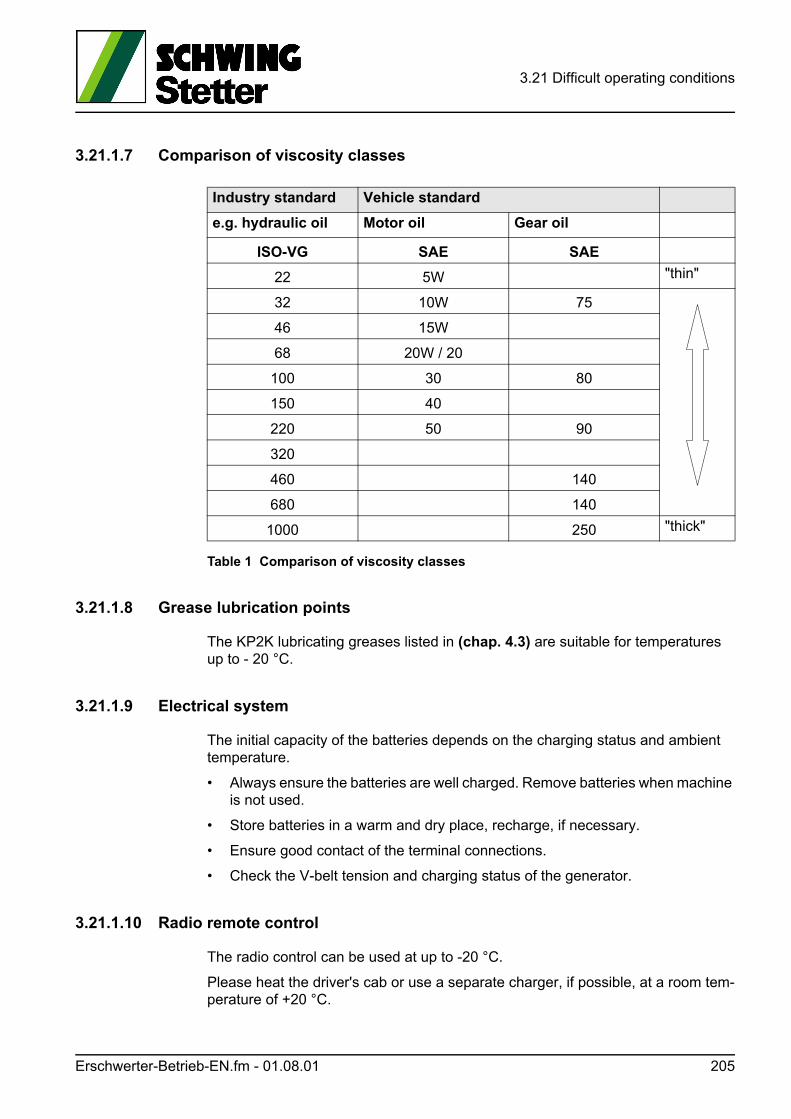
3.21 Difficult operating conditions
3.21.1.7 Comparison of viscosity classes
Table 1 Comparison of viscosity classes
3.21.1.8 Grease lubrication points
The KP2K lubricating greases listed in (chap. 4.3) are suitable for temperatures up to - 20 °C.
3.21.1.9 Electrical system
The initial capacity of the batteries depends on the charging status and ambient temperature.
• Always ensure the batteries are well charged. Remove batteries when machine is not used.
• Store batteries in a warm and dry place, recharge, if necessary.
• Ensure good contact of the terminal connections.
• Check the V-belt tension and charging status of the generator.
3.21.1.10 Radio remote control
The radio control can be used at up to -20 °C.
Please heat the driver's cab or use a separate charger, if possible, at a room tem-perature of +20 °C.
Industry standard Vehicle standard
e.g. hydraulic oil Motor oil Gear oil
ISO-VG SAE SAE
22 5W "thin"
32 10W 75
46 15W
68 20W / 20
100 30 80
150 40
220 50 90
320
460 140
680 140
1000 250 "thick"
Erschwerter-Betrieb-EN.fm - 01.08.01 205
3.21 Difficult operating conditions
Information
Charging the battery becomes problematic at temperatures below +10 °C.
3.21.1.11 Setting up the machine
Frost, thaw, rain, etc. can significantly change the load-bearing capacity of the ground.
• Before starting to work, check the ground conditions and monitor them during operation.
3.21.1.12 Cold start
• Move the machine into an enclosed building overnight, if possible.
• After a cold start, operate the hydraulic system without a load at a low speed for several minutes.
This will heat up the aggregates and oil, building up a stable lubricating film.
• Extend the connection pieces at a low pump speed.
• Raise the placing boom at a low pump speed and run through all boom cylin-ders.
• Run the concrete pump with a reduced stroke count until the hydraulic system reaches the operating temperature.
3.21.1.13 Pump operation
In general, heated concrete is used at ambient temperatures below freezing. Ex-pect short setting times.
In order to prevent "bleeding", the heated concrete must be mixed thoroughly.
• Keep pumping breaks as short as possible.
• Clean the pumping line and concrete pump immediately after pumping.
• Be sure to remove residual water immediately and completely after cleaning.
206 Erschwerter-Betrieb-EN.fm - 01.08.01
3.21 Difficult operating conditions
3.21.1.14 Decommissioning
• Clean the machine after the work assignment.
• Clean steps, platforms, etc. from ice and dirt.
• Position the machine on firm, dry ground.
• Secure the machine properly from rolling away.
• Only release the parking brake (can freeze) if the machine can be otherwise se-cured effectively from rolling away.
3.21.2 High ambient temperatures
ACHTUNG! Attention!
Material damage due to overflowing fluids!
Overflowing fluids can cause serious material damage and even fires.
Always make sure that containers are filled according to regulations and keep the containers closed.
3.21.2.1 General information
In principle, it is useful to keep an eye on the temperatures of the pumping line, in-dividual aggregates and fluids at high ambient temperatures.
If possible, set up the machine so that it is protected from direct sunlight.
Machine and pumping line should be painted brightly.
Relocate separate pumping lines preferably in the shade, cover, if necessary.
Please note, the VECTOR control system in our truck-mounted concrete pumps monitors the hydraulic oil temperature and reduces the power of the concrete pump starting at approx. +85 °C. The concrete pump switches off at +95 °C.
Furthermore, the temperatures of the motor coolant and compressors can also be monitored.
This monitoring can also be combined with a switch off function.
It is, therefore, useful to ensure optimum cooling:
• Fill all the oils and the coolant up to the max. mark.
• Prevent fluids from overflowing. This can damage the machine.
• Keep the blades of the motor radiator and hydraulic cooler clean.
• Clean more often with high dust accumulation.
• Replace the insert of the motor air filter, if necessary.
• Do not open the maintenance flaps in order to augment the cooling effect.This could interfere with the air circulation and have the opposite effect.
Erschwerter-Betrieb-EN.fm - 01.08.01 207
3.21 Difficult operating conditions
• Ensure that the hydraulic system is configured correctly. For example, a pres-sure relief valve that is set too low will cause the oil temperature to increase be-cause oil is continuously discharged under high pressure through a small cross section.
• Replace the water in the water box with fresh water if it becomes too warm.
• Sprinkle the differential cylinders of the concrete pump with a water hose.
ACHTUNG! Attention!
Do not use water to cool down hydraulic oil box!
Cooling down the box causes heavy water condensation inside the box.
Condensate water in the hydraulic oil can cause material damage to the hydraulic system.
• Do not pump with maximum stroke rate. High stroke rates increase the temperature of the hydraulic system and are ex-tremely pointless for stiff concrete, as they are then sucked in poorly.
• Prevent air from being sucked in. Air in the pumping pipes can cause the boom to move and the end hose to flail about! Always make sure that the agitator shaft is in the concrete so that no air can be sucked in.
• Run the system in idle during pumping breaks.This will continue pumping the hydraulic oil through the radiator, and the motor oil transporting the heat away from the hot turbo charger.
3.21.2.2 Vehicle motor and integrated motor
Observe the manufacturer's operating instructions. Experience has shown that at least the following measures are required:
• Change oil and filter, unless a suitable multi-purpose oil is being used.
• Adapt frost protector for air system.
3.21.2.3 Water system
• Also make sure that the water case is well filled because water may be required to cool the concrete pump.
208 Erschwerter-Betrieb-EN.fm - 01.08.01
3.21 Difficult operating conditions
3.21.2.4 Hydraulic system
The multi-purpose hydraulic oil filled in at the Herne plant covers the viscosity class VG 46 and the viscosity class VG 68, intended for tropical applications, see (“Rec-ommended lubricants and fuels” on page 227).
If a single-purpose oil VG 46 is used, the oil must be changed to VG 68. When changing the oil, also exchange the filters.
Should these oils be insufficient despite having configured the hydraulic system properly and despite optimum cooling, see (chap. 3.21.2.1), please contact us.
Please note that a "thicker" hydraulic oil with viscosity class VG 100 has a cold-start limit of +3 °C, and the optimum operating viscosity is significantly higher.
This can cause difficulties in areas with highly variable temperatures (night/day), see (Fig. 142 Viscosity-temperature diagram).
3.21.2.5 Air system
Use a compressor oil for the reciprocating compressor of viscosity class VG 150.
The synthetic oil prescribed for our rotation compressors is suitable for tempera-tures up to +40 °C.
This is sufficient for the normal concrete pump application (no continuous opera-tion).
Should the VECTOR control cause the machine to shutdown nevertheless due to overheating, please contact us.
3.21.2.6 Gear
The gear oils recommended in (chap. 4.3) are suitable for continuous ambient tem-peratures of approx. -10 °C to approx. +40 °C.
Information
A gear oil change is only required at continuous temperatures below +40 °C.
It is also possible to use a multi-purpose oil.
If such an oil is not available, please use an oil with a higher viscosity level than the recommended gear oil (see gear type plate), i.e. VG 320 instead of VG 220 (indus-trial gear oil) or SAE 140 instead of SAE 90 (vehicle gear oil), see (Table 1 Com-parison of viscosity classes).
Erschwerter-Betrieb-EN.fm - 01.08.01 209
3.21 Difficult operating conditions
3.21.2.7 Grease lubrication points
The KP2K lubricating greases listed in (chap. 4.3) are suitable for temperatures of -20° to +140 °C.
3.21.2.8 Electrical system
Check the acid level of the battery cells more frequently at high ambient tempera-tures.
Only refill with distilled water!
3.21.2.9 Radio remote control
The radio control can be used at up to +60 °C.
3.21.2.10 Setting up the machine
The load-bearing capacity of heat-sensitive subsoils, such as asphalt, decreases as the ambient temperature rises.
• Make sure the ground is firm.
3.21.2.11 Cold start
Make sure in particular to start the system gently when the machine is equipped with special lubrications for high temperatures.
Lubricants of high viscosity (viscous) only reach their maximum optimum operating viscosity later on.
The hydraulic pumps can be damaged, as described under in (chap. 3.21.1.12).
210 Erschwerter-Betrieb-EN.fm - 01.08.01
3.21 Difficult operating conditions
3.21.2.12 Pump operation
The concrete is frequently prepared in hot areas with cooled aggregates or cooled water.
The placement of the concrete should take place preferably during cooler periods of the time, such as in the morning or evening.
• Rinse a heated pumping line with water before pumping.
• Use a somewhat mushier start-up mixture for long lines.
• Make sure that the concrete can be pumped easily.
• Avoid extended breaks.
Cover the concrete in the filling hopper of the concrete pump with wet bags, for example.
• Start cleaning immediately after pumping.
3.21.2.13 Decommissioning
• Let the machine idle for some minutes with the pump drive active.
This way, the turbo charger transports the heat away from the diesel engine and cools the hydraulic oil by continuing to pump it through the radiator.
Erschwerter-Betrieb-EN.fm - 01.08.01 211

3.21 Difficult operating conditions
212 Erschwerter-Betrieb-EN.fm - 01.08.01
3.22 Decommissioning
3.22 Decommissioning
If the machine is to be decommissioned for an extended period of time, please ob-serve the following list.
3.22.1 Tasks prior to decommissioning
1. Clean and lubricate the machine thoroughly.
2. Check the concentration of antifreeze for liquid-cooled motors and top up if necessary.
3. Drain condensation water from fuel, hydraulic and air system reservoirs.
4. Fill fuel tank and oil box to the brim. If the oil is in poor condition, change it.
5. Fill all gearboxes with the prescribed amount of oil.If the oil is in poor condition, change it.
6. Apply acid-free grease to bare machine parts or spray them with preserving oil.
7. Preserve concrete pumping pipes by pushing a cotton waste plug soaked in preserving oil through the pumping line.
8. Retract all hydraulic cylinders.
9. Set all control elements to position 0.
10. Relieve pressure accumulators.
11. Preserve the motor as described in the motor’s operating instructions.
12. Drain water from the reservoir, water box and water pump.
13. Spray water box with a rust-protective agent.
14. Close all openings and waterproof.
15. Jack up the vehicle in order to let down the tyres.
16. Check tyre air pressure.
17. Release parking brake.
18. Remove starter batteries (lead-acid batteries) and store in a cool (5-15 °C), clean and dry location.
19. Permanently connect batteries to a charger with trickle charging, or charge at monthly intervals (no quick charging). Then check the fluid level.
Stilllegung-EN.fm - 01.05.01 213
3.22 Decommissioning
ACHTUNG! Attention!
Never allow batteries to remain discharged!
Deep discharge will destroy them!
Frost can cause the housing of discharged batteries to rupture due to freezing of the contents!
In order to prevent premature ageing, up to destruction, the above instructions must be observed!
Observe further instructions in chapter 4.60, in addition to the operating instructions from the motor or chassis manufacturer.
3.22.2 Recommissioning
1. Remove preservation.
2. Check all oil levels.
3. Empty hydraulic oil box to inspection glass level, when full to the brim.
4. Check and install batteries.
5. Check tyre air pressure.
6. Completely lubricate machine.
7. Carry out functional testing.
Information
For storage of the machine under difficult conditions, special regulations apply.
Difficult conditions include, for example:
• Storage periods of over 6 months.
• High air humidity.
• Sea air, etc.
Contact SCHWING customer service.
214 Stilllegung-EN.fm - 01.05.01
3.23 Technical preconditions for concreting
3.23 Technical preconditions for concreting
Information
Pumped concrete is not a special concrete, but a standardised quality concrete.
3.23.1 Properties of pumped concrete
• A minimum fine grain content of approx. 400 kg per m³ (with a maximum grain size of 32 mm).
• A minimum cement content of approx. 240 kg per m³ (with a maximum grain size of 32 mm).
• Water/Cement ratio of 0.42 w/c - 0.65 w/c.
• Grain composition according to grading curve.
• Consistency of K 2 to K 3.
3.23.2 Errors that inhibit pumping
• Incorrect concrete composition (see above).
• Poor upkeep of the machine and pumping line (cleaning!).
• Inadequate mixing quality.
• Separation caused by improper transport.
• Incorrect maximum grain size selected based on diameter of pumping line.
• “Bleeding” of fresh concrete.
• Incorrect use of admixtures.
Betontechnologische-Vorauss-EN.fm - 01.04.01 215

3.23 Technical preconditions for concreting
216 Betontechnologische-Vorauss-EN.fm - 01.04.01
Trennblatt_Kapitel-Wartung-EN
4 Maintenance
This chapter contains maintenance instructions for concrete pumps.
Further measures should be carried out by SCHWING’s customer service department or by trained and qualified personnel. Otherwise, the warranty and liability shall become void for this machine.
.fm 217

4 Maintenance
218 Trennblatt_Kapitel-Wartung-EN.fm - 01.00.01
4.1 General maintenance instructions
4.1 General maintenance instructions
Carry out the maintenance on time and with care.
We recommend copying the maintenance schedule (chap. 4.6).
The maintenance personnel can then acknowledge the work carried out on the copies.
Schwing expressly prohibits any maintenance work carried out by personnel who are not specially trained and authorised.
GEFAHR! Danger!
Severe to fatal accidents and serious material damage can be caused by un-qualified personnel!
Should you not have trained personnel and appropriate workshop equipment, com-mission the SCHWING customer service to service your machine.
4.1.1 Maintenance work on special equipment
Maintenance work on special equipment is described in chapter “Special equip-ment” on page 357.
4.1.2 Cleanliness
• Clean all units located within the work area before starting to work.
ACHTUNG! Attention!
Material damage caused by high-pressure cleaner!
The use of high-pressure cleaners can damaged sensitive parts!
Do not use a steam jet to clean rubber and electrical parts.
• As a rule, prevent dirt from entering - especially in the hydraulic system.
• Lubricate your entire machine after a high-pressure cleaning.
Allgemeine_Wartungshinweise-EN.fm - 01.14.01 219
4.1 General maintenance instructions
4.1.3 Corrosion protection
Heavy rust weakens the material and may cause fractures and cracks.
• Repair damaged painted surfaces within due time and grease bare machine parts.
4.1.4 Checking the oil level
In general, take the following points into account when checking the oil:
• Make sure that the machine is level
• Switch off the drive approx. 10 min. before performing an oil check
• Move mobile machines into the transport position and brace them (outrigger in transport position).
4.1.5 Oil change
• Drain the oil while it is still at operating temperature in order to flush out contam-inants better.
VORSICHT! Caution!
Risk of injury caused by hydraulic oil!
Hydraulic fluid can cause irritation to the skin and eyes!
Always wear suitable protective clothing.
• Always fill hydraulic fluid from clean vessels through the filling hole on the tank provided for the purpose.
• If possible, use flushing or filtration units to add the new oil.
VORSICHT! Caution!
Danger caused by pressure rise in the oil box!
Do not fill reservoir with pressure! Make sure that the displaced air can easily es-cape from the reservoir.
Hang the filling hose loosely in the oil box. Never screw in the filling hose so that it is airtight!
Always prevent containers from overflowing.
Check the oil level after each test run.
Do not store hydraulic oil barrels outdoors.
220 Allgemeine_Wartungshinweise-EN.fm - 01.14.01
4.1 General maintenance instructions
Do not store hydraulic oil barrels horizontally.
• Prior to removal, the barrel must remain stationary for an extended period of time.Contaminants can deposit easily.
Never roll hydraulic oil barrels to the filling site.
Make sure not to insert the suction hose too deep into the hydraulic oil barrel in order to avoid sucking in contaminants from the barrel floor.
Information
Before each oil change, we recommend taking an oil sample and examining it for discolouration and solid materials (suspended particles).
This makes it possible to determine early on whether preventive maintenance measures need to be initiated.
4.1.6 Draining condensation water
Humidity and fluctuating temperatures form condensation in hydraulic oil boxes, which mixes with the oil.
As the ratio of water increases, the lubricating power of the mixture decreases rap-idly.
Solution:
After several days of not using the machine, the water separates from the oil and collects at the bottom of the box.
By opening the drain screw on the hydraulic oil box, you can then drain the water from the bottom of the box.
Information
Best downtime!
The hydraulic oil used at SCHWING requires a downtime period of at least 2 days in order to achieve good results.
4.1.7 Seals and fuse elements
• Make sure that no seals, spring washers, etc. are lost when removing top cov-ers, closing screw plugs, and the like.
• Before closing them again, clean the sealing surfaces of the screws and covers, etc. and make sure not to damage them.
• Replace the seals, split pins, spring washers, etc. immediately if they are worn or damaged.
Allgemeine_Wartungshinweise-EN.fm - 01.14.01 221
4.1 General maintenance instructions
4.1.8 Lubrication
Clean grease nipples before and after lubrication.
Remove any excess grease from the lubrication points.
4.1.9 Leaks
Check all containers, hoses, screw connections, etc. regularly for leaks.
ACHTUNG! Attention!
Environmental damage caused by flowing out oil!
Check the system for oil leaks and eliminate their causes.
WARNUNG! Warning!
Risk of serious injury due to leaks in lines and tubes!
Bursting lines or operating material emerging under pressure can cause serious in-juries.
Immediately replace any damaged tubes and damaged or moist hydraulic hos-es.
4.1.10 Repairs, exchange
Information
It may be less expensive to exchange complete units instead of repairing them.
Contact SCHWING’s customer service for an individual consultation.
Only use original SCHWING spare parts for repairs or replacements.
SCHWING will not be held liable for damage caused by use of third-party products or improper equipment.
Only use mineral oil-based greases for installation work on the hydraulic sys-tem.
If a unit (pump motor, etc.) fails, flush out the entire hydraulic system and re-place the filters in order to prevent consequential damages caused by metallic dust.
222 Allgemeine_Wartungshinweise-EN.fm - 01.14.01
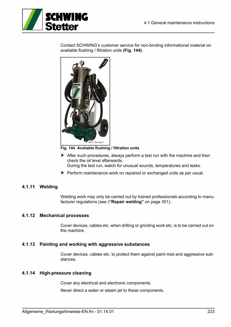
4.1 General maintenance instructions
Contact SCHWING’s customer service for non-binding informational material on available flushing / filtration units (Fig. 144).
Fig. 144 Available flushing / filtration units
After such procedures, always perform a test run with the machine and then check the oil level afterwards. During the test run, watch for unusual sounds, temperatures and leaks.
Perform maintenance work on repaired or exchanged units as per usual.
4.1.11 Welding
Welding work may only be carried out by trained professionals according to manu-facturer regulations (see (“Repair welding” on page 351).
4.1.12 Mechanical processes
Cover devices, cables etc. when drilling or grinding work etc. is to be carried out on the machine.
4.1.13 Painting and working with aggressive substances
Cover devices, cables etc. to protect them against paint mist and aggressive sub-stances.
4.1.14 High-pressure cleaning
Cover any electrical and electronic components.
Never direct a water or steam jet to these components.
Allgemeine_Wartungshinweise-EN.fm - 01.14.01 223
4.1 General maintenance instructions
Any penetrating moisture leads to malfunctions and can destroy electronics and electrical components completely.
4.1.15 Electrically powered machines
• Have an electrician disconnect the power supply to such machines prior to car-rying out repair work on the respective machine.
GEFAHR! Danger!
Danger to life by electric shock!
Working on systems still connected to a power source poses an acute danger to life from electric shock!
Always turn off all main switches and secure them against being turned back on without authorisation.
Repairs on electrical systems may only be performed by electricians!
224 Allgemeine_Wartungshinweise-EN.fm - 01.14.01
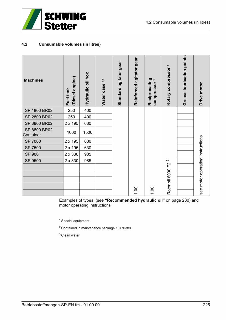
4.2 Consumable volumes (in litres)
4.2 Consumable volumes (in litres)
Examples of types, (see “Recommended hydraulic oil” on page 230) and motor operating instructions
1 Special equipment
2 Contained in maintenance package 10170389
3 Clean water
Machines
Fu
el t
ank
(Die
sel e
ng
ine)
Hyd
rau
lic o
il b
ox
Wat
er c
ase
1.3
Sta
nd
ard
ag
itat
or
gea
r
Rei
nfo
rced
ag
itat
or
gea
r
Rec
ipro
cati
ng
co
mp
ress
or
1
Ro
tary
co
mp
ress
or
1
Gre
ase
lub
rica
tio
n p
oin
ts
Dri
ve m
oto
r
SP 1800 BR02 250 400
1.00
1.00
Rot
or o
il 80
00 F
2 2
see
mot
or o
pera
ting
inst
ruct
ions
SP 2800 BR02 250 400
SP 3800 BR02 2 x 195 630
SP 8800 BR02Container
1000 1500
SP 7000 2 x 195 630
SP 7500 2 x 195 630
SP 900 2 x 330 985
SP 9500 2 x 330 985
Betriebsstoffmengen-SP-EN.fm - 01.00.00 225

4.2 Consumable volumes (in litres)
226 Betriebsstoffmengen-SP-EN.fm - 01.00.00
4.3 Recommended lubricants and fuels
4.3 Recommended lubricants and fuels
GEFAHR! Danger!
Oil under pressure is very dangerous!
The following points must be observed:
• Only qualified personnel may work on hydraulic systems.
• Personal protective equipment must be worn during work (safety glasses, suit-able gloves and clothing).
• Work only on unpressurised systems. The entrapped oil can also be under pressure when the drive is at standstill and pressure accumulator is unpressur-ised.
• If, for example, systems under pressure need to be opened when venting, mount a breather line first while the system is depressurised or use the existing mini-measurement connection.
• If this is not possible due to a lack of space, for example, make sure that nobody can be hit by escaping oil.
• Open the breather screw very carefully until oil emerges. By no means open fur-ther or remove the junction.
GEFAHR! Danger!
Danger caused by oil jet!
Hydraulic oil escaping under pressure can penetrate the skin and cause severe tis-sue damage.
This represents an acute medical emergency.
Immediately consult a doctor!
Even with a minor injury caused by an oil jet, insist on immediate medical help!
Schmier-Betriebstoffempfehlung-EN.fm - 01.22.01 227
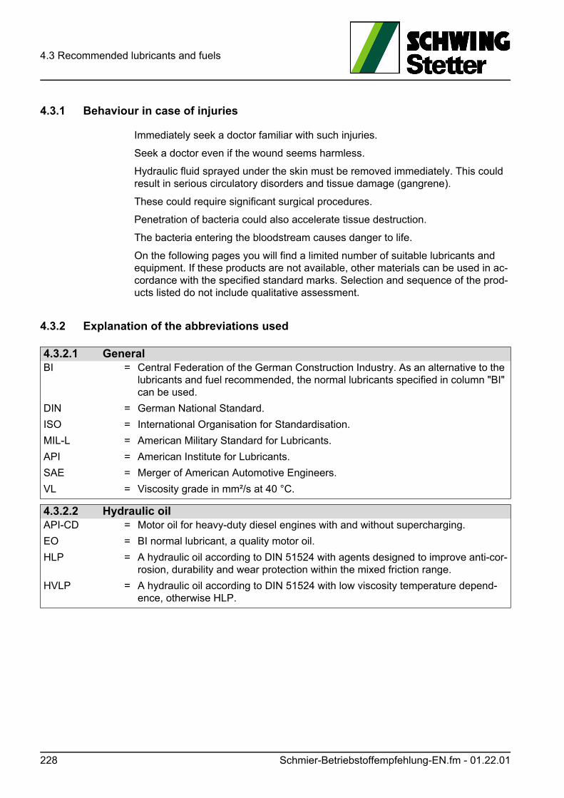
4.3 Recommended lubricants and fuels
4.3.1 Behaviour in case of injuries
Immediately seek a doctor familiar with such injuries.
Seek a doctor even if the wound seems harmless.
Hydraulic fluid sprayed under the skin must be removed immediately. This could result in serious circulatory disorders and tissue damage (gangrene).
These could require significant surgical procedures.
Penetration of bacteria could also accelerate tissue destruction.
The bacteria entering the bloodstream causes danger to life.
On the following pages you will find a limited number of suitable lubricants and equipment. If these products are not available, other materials can be used in ac-cordance with the specified standard marks. Selection and sequence of the prod-ucts listed do not include qualitative assessment.
4.3.2 Explanation of the abbreviations used
4.3.2.1 GeneralBI = Central Federation of the German Construction Industry. As an alternative to the
lubricants and fuel recommended, the normal lubricants specified in column "BI" can be used.
DIN = German National Standard.
ISO = International Organisation for Standardisation.
MIL-L = American Military Standard for Lubricants.
API = American Institute for Lubricants.
SAE = Merger of American Automotive Engineers.
VL = Viscosity grade in mm²/s at 40 °C.
4.3.2.2 Hydraulic oilAPI-CD = Motor oil for heavy-duty diesel engines with and without supercharging.
EO = BI normal lubricant, a quality motor oil.
HLP = A hydraulic oil according to DIN 51524 with agents designed to improve anti-cor-rosion, durability and wear protection within the mixed friction range.
HVLP = A hydraulic oil according to DIN 51524 with low viscosity temperature depend-ence, otherwise HLP.
228 Schmier-Betriebstoffempfehlung-EN.fm - 01.22.01
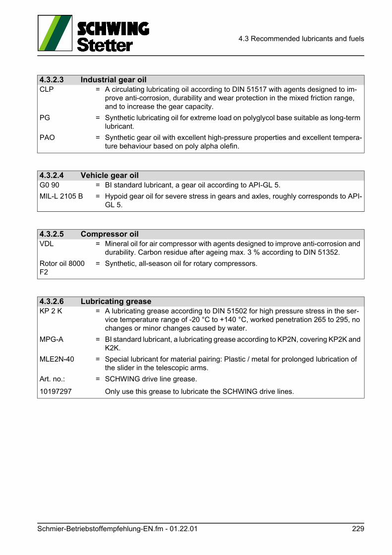
4.3 Recommended lubricants and fuels
4.3.2.3 Industrial gear oilCLP = A circulating lubricating oil according to DIN 51517 with agents designed to im-
prove anti-corrosion, durability and wear protection in the mixed friction range, and to increase the gear capacity.
PG = Synthetic lubricating oil for extreme load on polyglycol base suitable as long-term lubricant.
PAO = Synthetic gear oil with excellent high-pressure properties and excellent tempera-ture behaviour based on poly alpha olefin.
4.3.2.4 Vehicle gear oilG0 90 = BI standard lubricant, a gear oil according to API-GL 5.
MIL-L 2105 B = Hypoid gear oil for severe stress in gears and axles, roughly corresponds to API-GL 5.
4.3.2.5 Compressor oilVDL = Mineral oil for air compressor with agents designed to improve anti-corrosion and
durability. Carbon residue after ageing max. 3 % according to DIN 51352.
Rotor oil 8000 F2
= Synthetic, all-season oil for rotary compressors.
4.3.2.6 Lubricating greaseKP 2 K = A lubricating grease according to DIN 51502 for high pressure stress in the ser-
vice temperature range of -20 °C to +140 °C, worked penetration 265 to 295, no changes or minor changes caused by water.
MPG-A = BI standard lubricant, a lubricating grease according to KP2N, covering KP2K and K2K.
MLE2N-40 = Special lubricant for material pairing: Plastic / metal for prolonged lubrication of the slider in the telescopic arms.
Art. no.:
10197297
= SCHWING drive line grease.
Only use this grease to lubricate the SCHWING drive lines.
Schmier-Betriebstoffempfehlung-EN.fm - 01.22.01 229
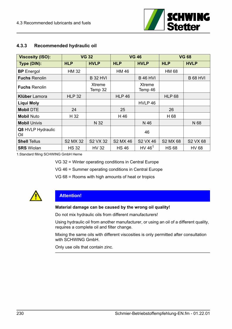
4.3 Recommended lubricants and fuels
4.3.3 Recommended hydraulic oil
VG 32 = Winter operating conditions in Central Europe
VG 46 = Summer operating conditions in Central Europe
VG 68 = Rooms with high amounts of heat or tropics
ACHTUNG! Attention!
Material damage can be caused by the wrong oil quality!
Do not mix hydraulic oils from different manufacturers!
Using hydraulic oil from another manufacturer, or using an oil of a different quality, requires a complete oil and filter change.
Mixing the same oils with different viscosities is only permitted after consultation with SCHWING GmbH.
Only use oils that contain zinc.
Viscosity (ISO): VG 32 VG 46 VG 68
Type (DIN): HLP HVLP HLP HVLP HLP HVLP
BP Energol HM 32 HM 46 HM 68
Fuchs Renolin B 32 HVI B 46 HVI B 68 HVI
Fuchs RenolinXtreme
Temp 32Xtreme
Temp 46
Klüber Lamora HLP 32 HLP 46 HLP 68
Liqui Moly HVLP 46
Mobil DTE 24 25 26
Mobil Nuto H 32 H 46 H 68
Mobil Univis N 32 N 46 N 68
Q8 HVLP Hydraulic Oil
46
Shell Tellus S2 MX 32 S2 VX 32 S2 MX 46 S2 VX 46 S2 MX 68 S2 VX 68
SRS Wiolan HS 32 HV 32 HS 46 HV 461 HS 68 HV 68
1.Standard filling SCHWING GmbH Herne
230 Schmier-Betriebstoffempfehlung-EN.fm - 01.22.01
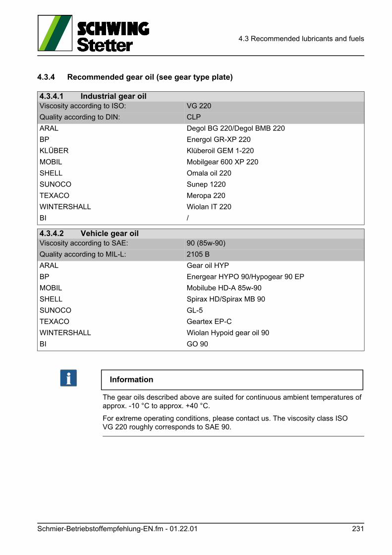
4.3 Recommended lubricants and fuels
4.3.4 Recommended gear oil (see gear type plate)
Information
The gear oils described above are suited for continuous ambient temperatures of approx. -10 °C to approx. +40 °C.
For extreme operating conditions, please contact us. The viscosity class ISO VG 220 roughly corresponds to SAE 90.
4.3.4.1 Industrial gear oilViscosity according to ISO: VG 220
Quality according to DIN: CLP
ARAL Degol BG 220/Degol BMB 220
BP Energol GR-XP 220
KLÜBER Klüberoil GEM 1-220
MOBIL Mobilgear 600 XP 220
SHELL Omala oil 220
SUNOCO Sunep 1220
TEXACO Meropa 220
WINTERSHALL Wiolan IT 220
BI /
4.3.4.2 Vehicle gear oilViscosity according to SAE: 90 (85w-90)
Quality according to MIL-L: 2105 B
ARAL Gear oil HYP
BP Energear HYPO 90/Hypogear 90 EP
MOBIL Mobilube HD-A 85w-90
SHELL Spirax HD/Spirax MB 90
SUNOCO GL-5
TEXACO Geartex EP-C
WINTERSHALL Wiolan Hypoid gear oil 90
BI GO 90
Schmier-Betriebstoffempfehlung-EN.fm - 01.22.01 231
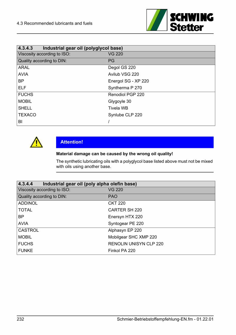
4.3 Recommended lubricants and fuels
ACHTUNG! Attention!
Material damage can be caused by the wrong oil quality!
The synthetic lubricating oils with a polyglycol base listed above must not be mixed with oils using another base.
4.3.4.3 Industrial gear oil (polyglycol base)Viscosity according to ISO: VG 220
Quality according to DIN: PG
ARAL Degol GS 220
AVIA Avilub VSG 220
BP Energol SG - XP 220
ELF Syntherma P 270
FUCHS Renodiol PGP 220
MOBIL Glygoyle 30
SHELL Tivela WB
TEXACO Synlube CLP 220
BI /
4.3.4.4 Industrial gear oil (poly alpha olefin base)Viscosity according to ISO: VG 220
Quality according to DIN: PAO
ADDINOL CKT 220
TOTAL CARTER SH 220
BP Enersyn HTX 220
AVIA Syntogear PE 220
CASTROL Alphasyn EP 220
MOBIL Mobilgear SHC XMP 220
FUCHS RENOLIN UNISYN CLP 220
FUNKE Finkol PA 220
232 Schmier-Betriebstoffempfehlung-EN.fm - 01.22.01
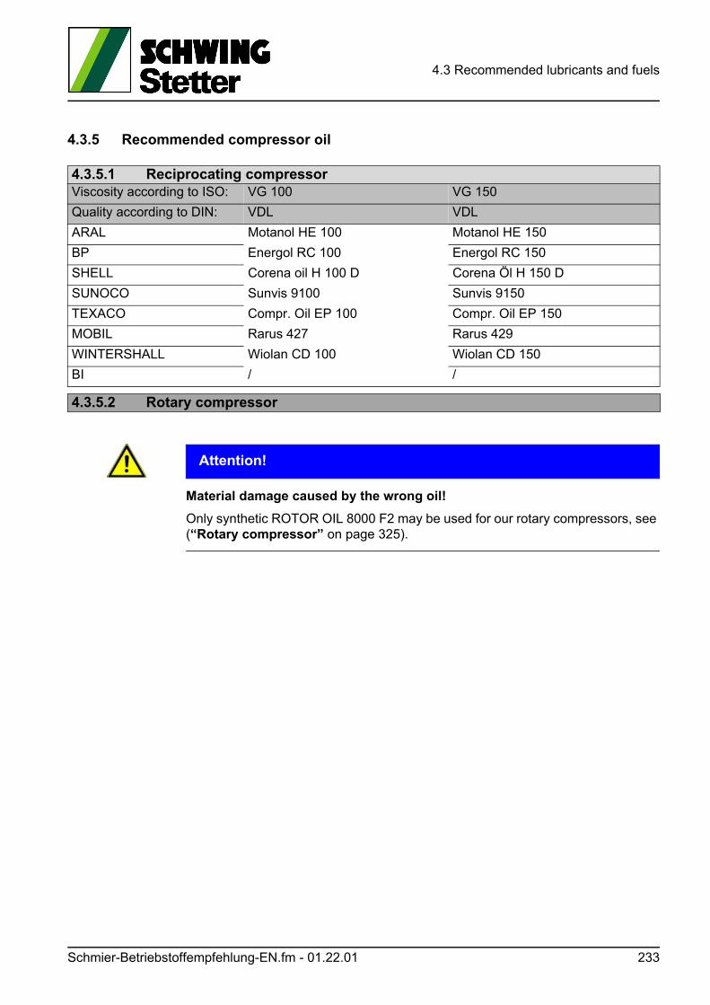
4.3 Recommended lubricants and fuels
4.3.5 Recommended compressor oil
ACHTUNG! Attention!
Material damage caused by the wrong oil!
Only synthetic ROTOR OIL 8000 F2 may be used for our rotary compressors, see (“Rotary compressor” on page 325).
4.3.5.1 Reciprocating compressorViscosity according to ISO: VG 100 VG 150
Quality according to DIN: VDL VDL
ARAL Motanol HE 100 Motanol HE 150
BP Energol RC 100 Energol RC 150
SHELL Corena oil H 100 D Corena Öl H 150 D
SUNOCO Sunvis 9100 Sunvis 9150
TEXACO Compr. Oil EP 100 Compr. Oil EP 150
MOBIL Rarus 427 Rarus 429
WINTERSHALL Wiolan CD 100 Wiolan CD 150
BI / /
4.3.5.2 Rotary compressor
Schmier-Betriebstoffempfehlung-EN.fm - 01.22.01 233
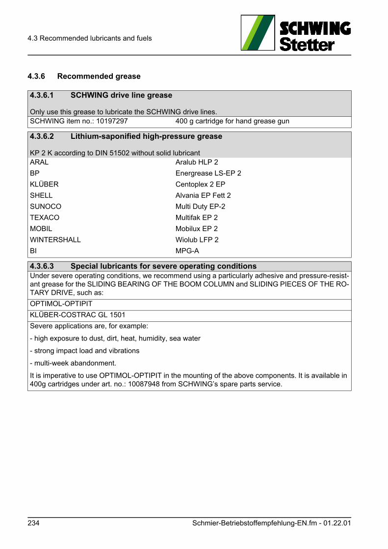
4.3 Recommended lubricants and fuels
4.3.6 Recommended grease
4.3.6.1 SCHWING drive line grease
Only use this grease to lubricate the SCHWING drive lines.SCHWING item no.: 10197297 400 g cartridge for hand grease gun
4.3.6.2 Lithium-saponified high-pressure grease
KP 2 K according to DIN 51502 without solid lubricantARAL Aralub HLP 2
BP Energrease LS-EP 2
KLÜBER Centoplex 2 EP
SHELL Alvania EP Fett 2
SUNOCO Multi Duty EP-2
TEXACO Multifak EP 2
MOBIL Mobilux EP 2
WINTERSHALL Wiolub LFP 2
BI MPG-A
4.3.6.3 Special lubricants for severe operating conditionsUnder severe operating conditions, we recommend using a particularly adhesive and pressure-resist-ant grease for the SLIDING BEARING OF THE BOOM COLUMN and SLIDING PIECES OF THE RO-TARY DRIVE, such as:
OPTIMOL-OPTIPIT
KLÜBER-COSTRAC GL 1501
Severe applications are, for example:
- high exposure to dust, dirt, heat, humidity, sea water
- strong impact load and vibrations
- multi-week abandonment.
It is imperative to use OPTIMOL-OPTIPIT in the mounting of the above components. It is available in 400g cartridges under art. no.: 10087948 from SCHWING’s spare parts service.
234 Schmier-Betriebstoffempfehlung-EN.fm - 01.22.01
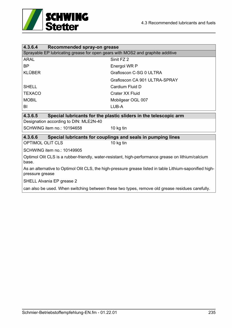
4.3 Recommended lubricants and fuels
4.3.6.4 Recommended spray-on greaseSprayable EP lubricating grease for open gears with MOS2 and graphite additive
ARAL Sinit FZ 2
BP Energol WR P
KLÜBER Grafloscon C-SG 0 ULTRA
Grafloscon CA 901 ULTRA-SPRAY
SHELL Cardium Fluid D
TEXACO Crater XX Fluid
MOBIL Mobilgear OGL 007
BI LUB-A
4.3.6.5 Special lubricants for the plastic sliders in the telescopic armDesignation according to DIN: MLE2N-40
SCHWING item no.: 10194658 10 kg tin
4.3.6.6 Special lubricants for couplings and seals in pumping linesOPTIMOL OLIT CLS
SCHWING item no.: 10149905
10 kg tin
Optimol Olit CLS is a rubber-friendly, water-resistant, high-performance grease on lithium/calcium base.
As an alternative to Optimol Olit CLS, the high-pressure grease listed in table Lithium-saponified high-pressure grease
SHELL Alvania EP grease 2
can also be used. When switching between these two types, remove old grease residues carefully.
Schmier-Betriebstoffempfehlung-EN.fm - 01.22.01 235
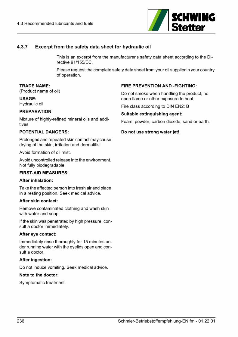
4.3 Recommended lubricants and fuels
4.3.7 Excerpt from the safety data sheet for hydraulic oil
This is an excerpt from the manufacturer’s safety data sheet according to the Di-rective 91/155/EC.
Please request the complete safety data sheet from your oil supplier in your country of operation.
TRADE NAME: (Product name of oil)
USAGE: Hydraulic oil
PREPARATION:
Mixture of highly-refined mineral oils and addi-tives
POTENTIAL DANGERS:
Prolonged and repeated skin contact may cause drying of the skin, irritation and dermatitis.
Avoid formation of oil mist.
Avoid uncontrolled release into the environment. Not fully biodegradable.
FIRST-AID MEASURES:
After inhalation:
Take the affected person into fresh air and place in a resting position. Seek medical advice.
After skin contact:
Remove contaminated clothing and wash skin with water and soap.
If the skin was penetrated by high pressure, con-sult a doctor immediately.
After eye contact:
Immediately rinse thoroughly for 15 minutes un-der running water with the eyelids open and con-sult a doctor.
After ingestion:
Do not induce vomiting. Seek medical advice.
Note to the doctor:
Symptomatic treatment.
FIRE PREVENTION AND -FIGHTING:
Do not smoke when handling the product, no open flame or other exposure to heat.
Fire class according to DIN EN2: B
Suitable extinguishing agent:
Foam, powder, carbon dioxide, sand or earth.
Do not use strong water jet!
236 Schmier-Betriebstoffempfehlung-EN.fm - 01.22.01

4.3 Recommended lubricants and fuels
ACCIDENTAL RELEASE MEASURES:
Person-related measures:
Ventilate affected rooms thoroughly. Avoid skin contact.
Environmental protection:
Prevent further leakage and flow into drains.
Erect sand or earth barriers or other suitable blocking measures.
In case of leakage into water, canalisation or soil, contact competent authorities.
CLEANING AND ABSORPTION:
Absorb or contain with sand, earth or absorbent material.
Shovel into a marked reservoir and dispose of according to local regulations.
HANDLING AND STORAGE:
Do not eat, drink, smoke or sniff during work. Avoid spilling.
Avoid sun, direct exposure to heat and strong oxidants during storage. Store dry and do not expose to large temperature switches.
PERSONAL PROTECTIVE EQUIPMENT:
Respiratory protection:
Use oil mist protective mask with filter for organ-ic vapours and particles.
Hand protection:
Protective gloves made of PVC or nitrile rubber, provided they meet safety standards
Eye protection:
Wear protective glasses in case of risk of splashing
Body protection:
Avoid skin contact, wear overalls.
GENERAL PROTECTIVE- AND HYGIENIC MEASURES:
Do not carry oil-soaked cleaning rags within the clothing. Do not eat, drink, smoke, sniff during work.
SAFETY-RELEVANT DATA:
See safety data sheet from the manufacturer.
DISPOSAL:
Product:
By approved waste disposal company. EU waste code no.: 130110
Packaging:
Completely emptied by approved waste dispos-al company.
MARKING:
Not subject to marking regulations according to EU directives. Observe national regulations!
Schmier-Betriebstoffempfehlung-EN.fm - 01.22.01 237

4.3 Recommended lubricants and fuels
238 Schmier-Betriebstoffempfehlung-EN.fm - 01.22.01
4.4 Spare parts and accessories
4.4 Spare parts and accessories
Information
Please observe the special instructions on safety components in chapter “Safety inspections” on page 345.
Spare parts and accessories must comply with the requirements defined by SCHWING.
This is guaranteed by the use of original SCHWING spare parts and accessories.
Use the article numbers of the machine-specific spare part catalogue in order to clearly identify the spare parts.
Spare parts with the same name can differ from one another slightly with regard to their shape and appearance, or in some cases not at all. However, the material quality, weight, function, etc. can be extremely different. Therefore, only use spare parts that comply with the specifications in the spare part catalogue.
SCHWING can also provide - beyond the legal provisions - original spare parts for older machines.
A wide range of accessories is also available.
SCHWING is not liable for damages resulting from the use of spare- and additional parts in non-compliance with the above requirements.
It is possible that, by using unsuitable or unauthorised accessories, the definition of "improper use" is met.
We recommend using our customer service for installing our original spare parts and accessories, as well as for all maintenance and repair work on your SCHWING machine.
Please note that SCHWING must rule out all warranties in the event that you or a third party commissioned by you carry out improper work.
SCHWING is also not liable in such cases for any consequences thereof.
Also see our "Delivery, service and payment terms and conditions".
The machine’s accessories should also be checked during safety-related inspec-tions, regardless of whether they can be installed securely or carried along loosely.
It should also be observed that, in addition to the soundness, this accessory is suit-able and approved by SCHWING.
Ersatzteile-Zubehoer-EN.fm - 01.05.02 239
4.4 Spare parts and accessories
4.4.1 Wear parts - Signs of wear
All components of a machine are subject to natural ageing. In addition, the wear of moving parts varies greatly depending on their load.
Careful maintenance and upkeep, as well as proper use of the machine can delay, but not entirely prevent, this so-called wear.
Since the wear and tear on various components of your SCHWING machine can vary greatly depending on their operating conditions, there are no universal rules to be applied for inspecting and replacing these parts.
However, there are signs indicating the need for an early review.
4.4.1.1 Case examples
Sand in the water box of the concrete pump
If, while conducting your regular cleaning of the water box, you notice that the water is becoming increasingly contaminated with concrete particulate matter, this means that the pumping pistons are worn.
If the same incident occurs again in the short term, the pumping cylinders also need to be replaced.
Hydraulic oil in the water box of the concrete pump
If you notice oil streaks on the water surface or a milky emulsion in the water box when the concrete pump is upright, the seal on the differential cylinders could be worn.
Water in the hydraulic oil
Small amounts of condensation in the hydraulic oil box are normal and should be drained regularly according to maintenance schedule.
A strong increase of the water content suggests water ingress from the outside.
It can also be assumed in this case that the seal in the differential cylinder is worn.
Dirt in the hydraulic oil
An oil analysis should be carried out first if clogging from an outside source can be excluded (e.g. refilling from an unclean reservoir), see (chap. 4.8.3).
The oil analysis determines the type of clogging.
In consequence thereof, e.g. the condition of the hydraulic pumps (metal particles) can be concluded.
If you determine that the clogging is caused by concrete particulate matter, the seals on the differential cylinders should be checked as well.
240 Ersatzteile-Zubehoer-EN.fm - 01.05.02
4.4 Spare parts and accessories
Information
Our machines are constantly optimised in the course of improving the specification. In doing so, a critical focus is on the improvement of the wear and tear.
Special components are also available for special applications.
If necessary, please ask our customer service for the optimal solution to your wear problem.
Ersatzteile-Zubehoer-EN.fm - 01.05.02 241

4.4 Spare parts and accessories
242 Ersatzteile-Zubehoer-EN.fm - 01.05.02
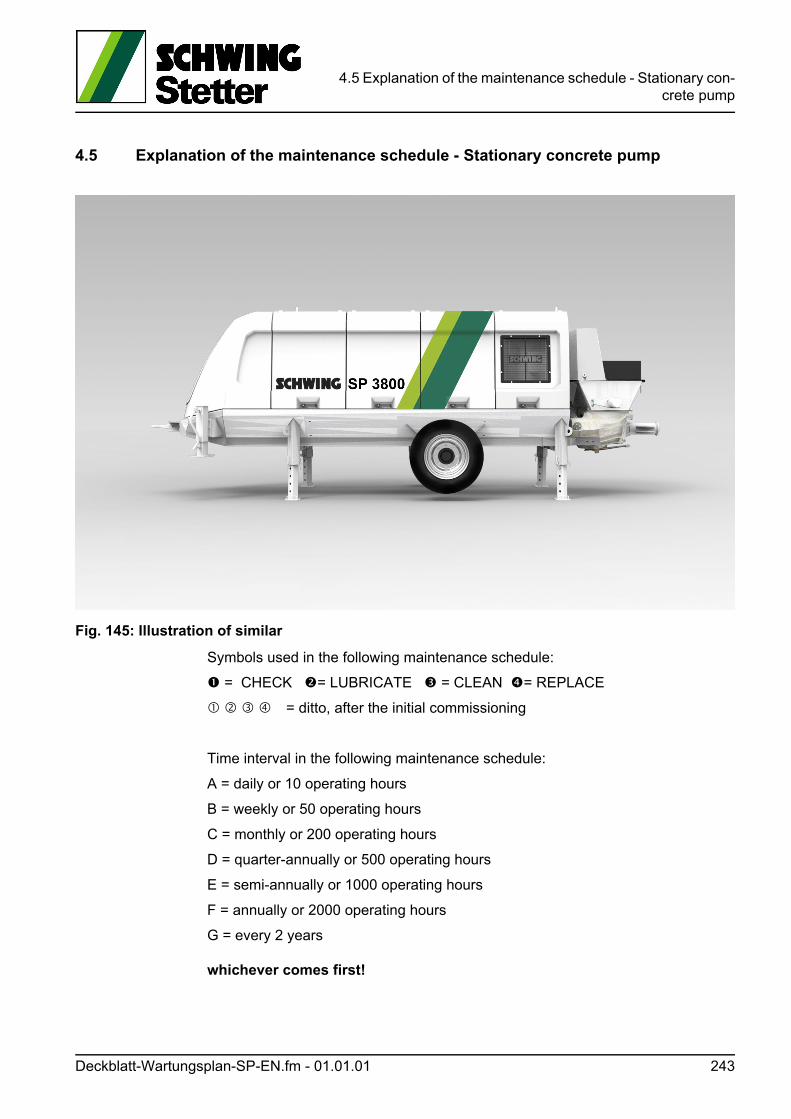
4.5 Explanation of the maintenance schedule - Stationary con-crete pump
4.5 Explanation of the maintenance schedule - Stationary concrete pump
Fig. 145: Illustration of similar
Symbols used in the following maintenance schedule:
= CHECK = LUBRICATE = CLEAN = REPLACE
= ditto, after the initial commissioning
Time interval in the following maintenance schedule:
A = daily or 10 operating hours
B = weekly or 50 operating hours
C = monthly or 200 operating hours
D = quarter-annually or 500 operating hours
E = semi-annually or 1000 operating hours
F = annually or 2000 operating hours
G = every 2 years
whichever comes first!
Deckblatt-Wartungsplan-SP-EN.fm - 01.01.01 243

4.5 Explanation of the maintenance schedule - Stationary con-crete pump
244 Deckblatt-Wartungsplan-SP-EN.fm - 01.01.01
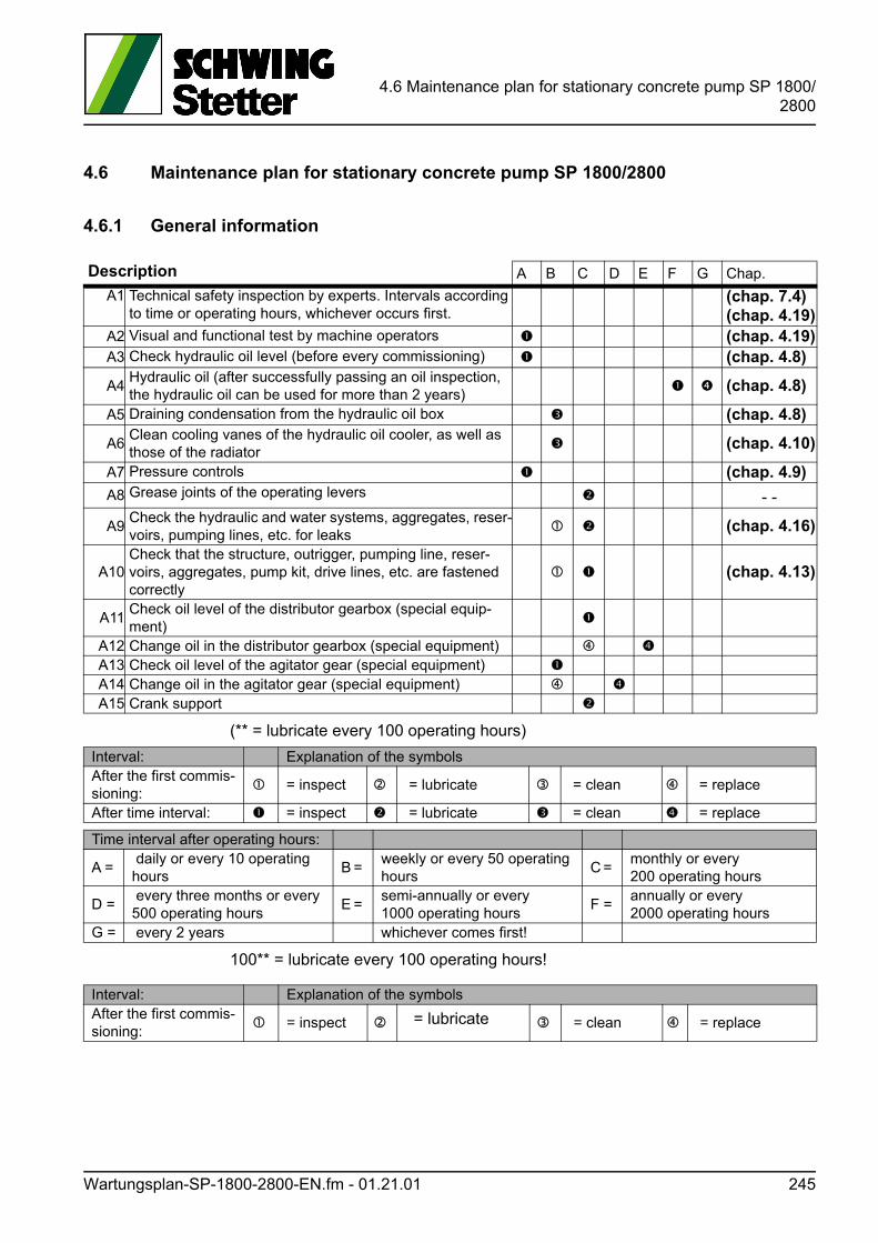
4.6 Maintenance plan for stationary concrete pump SP 1800/2800
4.6 Maintenance plan for stationary concrete pump SP 1800/2800
4.6.1 General information
(** = lubricate every 100 operating hours)
100** = lubricate every 100 operating hours!
Description A B C D E F G Chap.
A1 Technical safety inspection by experts. Intervals according to time or operating hours, whichever occurs first.
(chap. 7.4)(chap. 4.19)
A2 Visual and functional test by machine operators (chap. 4.19)A3 Check hydraulic oil level (before every commissioning) (chap. 4.8)
A4Hydraulic oil (after successfully passing an oil inspection, the hydraulic oil can be used for more than 2 years)
(chap. 4.8)
A5 Draining condensation from the hydraulic oil box (chap. 4.8)
A6Clean cooling vanes of the hydraulic oil cooler, as well as those of the radiator
(chap. 4.10)
A7 Pressure controls (chap. 4.9)
A8 Grease joints of the operating levers - -
A9Check the hydraulic and water systems, aggregates, reser-voirs, pumping lines, etc. for leaks
(chap. 4.16)
A10Check that the structure, outrigger, pumping line, reser-voirs, aggregates, pump kit, drive lines, etc. are fastened correctly
(chap. 4.13)
A11Check oil level of the distributor gearbox (special equip-ment)
A12 Change oil in the distributor gearbox (special equipment) A13 Check oil level of the agitator gear (special equipment) A14 Change oil in the agitator gear (special equipment) A15 Crank support
Interval: Explanation of the symbolsAfter the first commis-sioning:
= inspect = lubricate = clean = replace
After time interval: = inspect = lubricate = clean = replace
Time interval after operating hours:
A = daily or every 10 operating hours
B = weekly or every 50 operating hours
C = monthly or every 200 operating hours
D = every three months or every 500 operating hours
E = semi-annually or every 1000 operating hours
F =annually or every 2000 operating hours
G = every 2 years whichever comes first!
Interval: Explanation of the symbolsAfter the first commis-sioning:
= inspect = lubricate = clean = replace
Wartungsplan-SP-1800-2800-EN.fm - 01.21.01 245
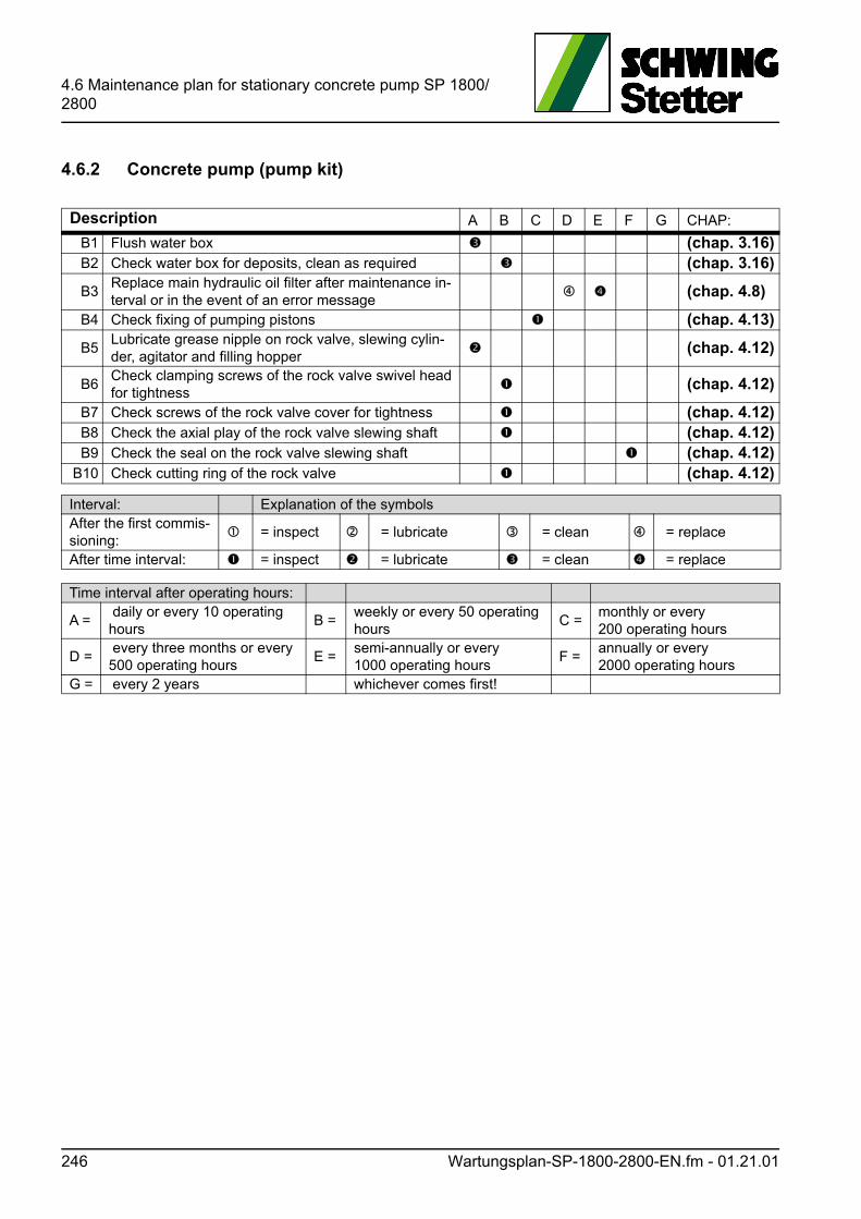
4.6 Maintenance plan for stationary concrete pump SP 1800/2800
4.6.2 Concrete pump (pump kit)
Description A B C D E F G CHAP:
B1 Flush water box (chap. 3.16)B2 Check water box for deposits, clean as required (chap. 3.16)
B3Replace main hydraulic oil filter after maintenance in-terval or in the event of an error message
(chap. 4.8)
B4 Check fixing of pumping pistons (chap. 4.13)
B5Lubricate grease nipple on rock valve, slewing cylin-der, agitator and filling hopper
(chap. 4.12)
B6Check clamping screws of the rock valve swivel head for tightness
(chap. 4.12)
B7 Check screws of the rock valve cover for tightness (chap. 4.12)B8 Check the axial play of the rock valve slewing shaft (chap. 4.12)B9 Check the seal on the rock valve slewing shaft (chap. 4.12)
B10 Check cutting ring of the rock valve (chap. 4.12)
Interval: Explanation of the symbolsAfter the first commis-sioning:
= inspect = lubricate = clean = replace
After time interval: = inspect = lubricate = clean = replace
Time interval after operating hours:
A = daily or every 10 operating hours
B =weekly or every 50 operating hours
C =monthly or every 200 operating hours
D = every three months or every 500 operating hours
E =semi-annually or every 1000 operating hours
F =annually or every 2000 operating hours
G = every 2 years whichever comes first!
246 Wartungsplan-SP-1800-2800-EN.fm - 01.21.01
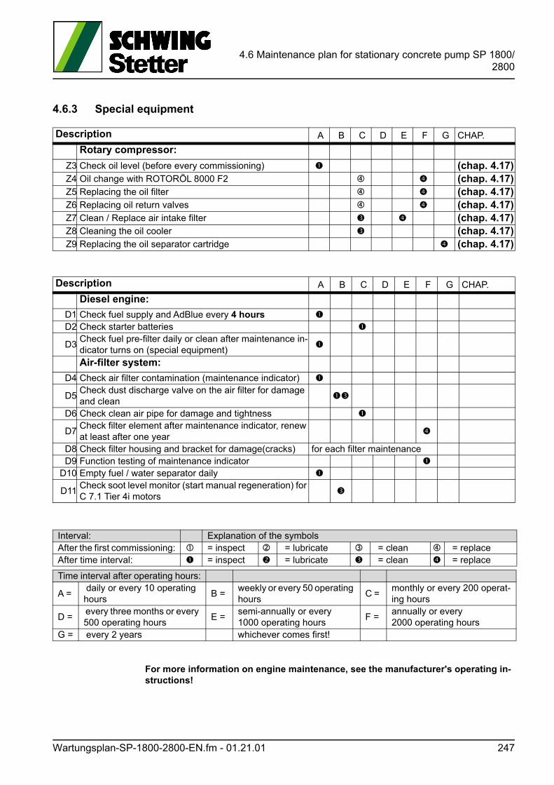
4.6 Maintenance plan for stationary concrete pump SP 1800/2800
4.6.3 Special equipment
For more information on engine maintenance, see the manufacturer's operating in-structions!
Description A B C D E F G CHAP.
Rotary compressor:
Z3 Check oil level (before every commissioning) (chap. 4.17)Z4 Oil change with ROTORÖL 8000 F2 (chap. 4.17)Z5 Replacing the oil filter (chap. 4.17)Z6 Replacing oil return valves (chap. 4.17)Z7 Clean / Replace air intake filter (chap. 4.17)Z8 Cleaning the oil cooler (chap. 4.17)Z9 Replacing the oil separator cartridge (chap. 4.17)
Description A B C D E F G CHAP.
Diesel engine:
D1 Check fuel supply and AdBlue every 4 hours D2 Check starter batteries
D3Check fuel pre-filter daily or clean after maintenance in-dicator turns on (special equipment)
Air-filter system:
D4 Check air filter contamination (maintenance indicator)
D5Check dust discharge valve on the air filter for damage and clean
D6 Check clean air pipe for damage and tightness
D7Check filter element after maintenance indicator, renew at least after one year
D8 Check filter housing and bracket for damage(cracks) for each filter maintenanceD9 Function testing of maintenance indicator
D10 Empty fuel / water separator daily
D11Check soot level monitor (start manual regeneration) for C 7.1 Tier 4i motors
Interval: Explanation of the symbolsAfter the first commissioning: = inspect = lubricate = clean = replaceAfter time interval: = inspect = lubricate = clean = replace
Time interval after operating hours:
A = daily or every 10 operating hours
B = weekly or every 50 operating hours
C = monthly or every 200 operat-ing hours
D = every three months or every 500 operating hours
E = semi-annually or every 1000 operating hours
F =annually or every 2000 operating hours
G = every 2 years whichever comes first!
Wartungsplan-SP-1800-2800-EN.fm - 01.21.01 247
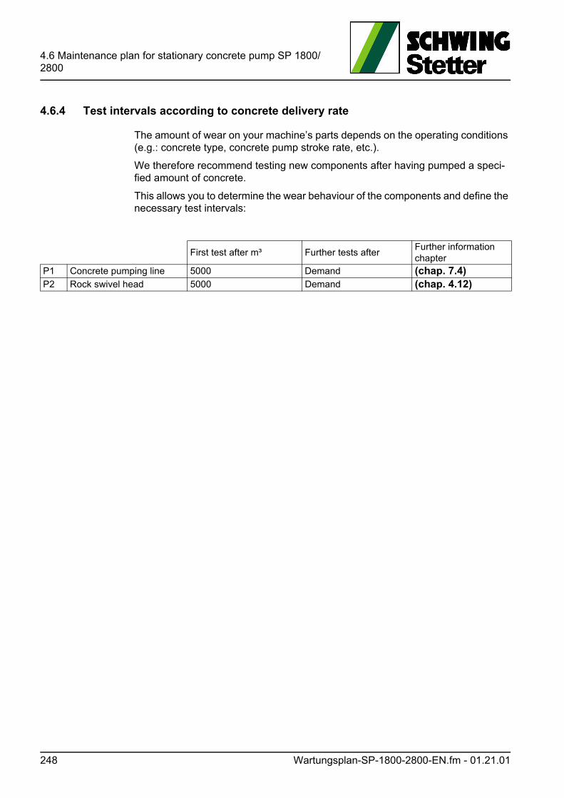
4.6 Maintenance plan for stationary concrete pump SP 1800/2800
4.6.4 Test intervals according to concrete delivery rate
The amount of wear on your machine’s parts depends on the operating conditions (e.g.: concrete type, concrete pump stroke rate, etc.).
We therefore recommend testing new components after having pumped a speci-fied amount of concrete.
This allows you to determine the wear behaviour of the components and define the necessary test intervals:
First test after m³ Further tests afterFurther information chapter
P1 Concrete pumping line 5000 Demand (chap. 7.4)P2 Rock swivel head 5000 Demand (chap. 4.12)
248 Wartungsplan-SP-1800-2800-EN.fm - 01.21.01
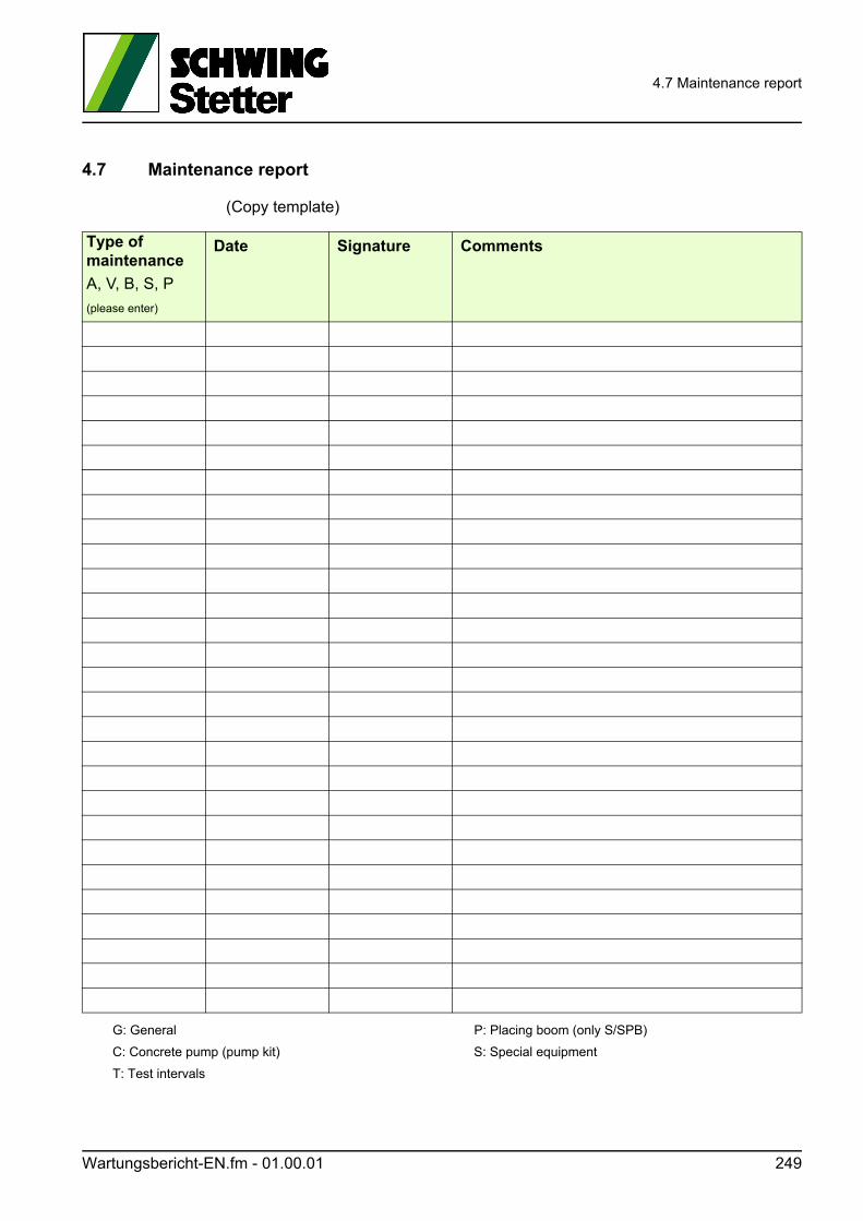
4.7 Maintenance report
4.7 Maintenance report
(Copy template)
Type of maintenance
A, V, B, S, P
(please enter)
Date Signature Comments
G: General P: Placing boom (only S/SPB)
C: Concrete pump (pump kit) S: Special equipment
T: Test intervals
Wartungsbericht-EN.fm - 01.00.01 249

4.7 Maintenance report
Type of maintenance
A, V, B, S, P
(please enter)
Date Signature Comments
G: General P: Placing boom (only S/SPB)
C: Concrete pump (pump kit) S: Special equipment
T: Test intervals
250 Wartungsbericht-EN.fm - 01.00.01
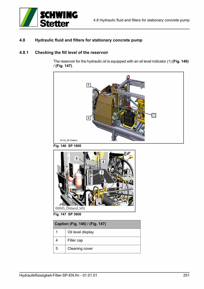
4.8 Hydraulic fluid and filters for stationary concrete pump
4.8 Hydraulic fluid and filters for stationary concrete pump
4.8.1 Checking the fill level of the reservoir
The reservoir for the hydraulic oil is equipped with an oil level indicator (1) (Fig. 146) / (Fig. 147).
Fig. 146 SP 1800
Fig. 147 SP 3800
Caption (Fig. 146) / (Fig. 147)
1 Oil level display
4 Filler cap
5 Cleaning cover
Hydraulikflüssigkeit-Filter-SP-EN.fm - 01.01.01 251
4.8 Hydraulic fluid and filters for stationary concrete pump
ACHTUNG! Attention!
If the oil level is too high, the reservoir can overflow when the oil is heated!
If the oil level is too low, there is a risk of damage because the hydraulic pumps suck air in.
Before starting the machine, always check the oil level!
Check the oil level only when the oil is cold, before you start the hydraulic pump drive for the first time prior to daily use.
To do so, the machine must be level in all directions.
When the oil is cold, the oil level must be shown in the middle of the oil level indi-cator (Fig. 146) / (Fig. 147) SP 3800. If present, ensure that the adhesive label is in good condition and replace it as required.
When warm, the hydraulic oil is expanded and the indicated oil level is not correct.
If necessary, top up the hydraulic oil via the filler cap (4) (Fig. 146) / (Fig. 147).
Do not mix different types of oil.
ACHTUNG! Attention!
Ensure absolute cleanliness!
To do this, we recommend using SCHWING’s flushing and filtration unit. For more information on this, contact SCHWING.
4.8.2 Filling the empty oil box
Top up the hydraulic oil box as described above.
Wait approx. 10 minutes until the oil is free of air bubbles and top up with more oil if necessary.
Run all functions.
Check the oil level again with cold oil while the machine is in a horizontal posi-tion.
Top up hydraulic oil if necessary.
4.8.3 Purity of the hydraulic oil
The purer the hydraulic oil is, the smoother the hydraulic systems and greasing units function. 75 percent of all system failures are due to damage to the inserted components - caused by impure hydraulic oil.
252 Hydraulikflüssigkeit-Filter-SP-EN.fm - 01.01.01
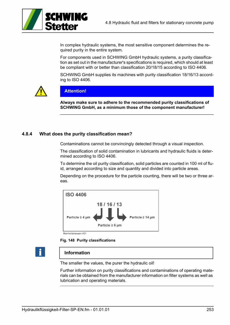
4.8 Hydraulic fluid and filters for stationary concrete pump
In complex hydraulic systems, the most sensitive component determines the re-quired purity in the entire system.
For components used in SCHWING GmbH hydraulic systems, a purity classifica-tion as set out in the manufacturer's specifications is required, which should at least be compliant with or better than classification 20/18/15 according to ISO 4406.
SCHWING GmbH supplies its machines with purity classification 18/16/13 accord-ing to ISO 4406.
ACHTUNG! Attention!
Always make sure to adhere to the recommended purity classifications of SCHWING GmbH, as a minimum those of the component manufacturer!
4.8.4 What does the purity classification mean?
Contaminations cannot be convincingly detected through a visual inspection.
The classification of solid contamination in lubricants and hydraulic fluids is deter-mined according to ISO 4406.
To determine the oil purity classification, solid particles are counted in 100 ml of flu-id, arranged according to size and quantity and divided into particle areas.
Depending on the procedure for the particle counting, there will be two or three ar-eas.
Fig. 148 Purity classifications
Information
The smaller the values, the purer the hydraulic oil!
Further information on purity classifications and contaminations of operating mate-rials can be obtained from the manufacturer information on filter systems as well as lubrication and operating materials.
Hydraulikflüssigkeit-Filter-SP-EN.fm - 01.01.01 253
4.8 Hydraulic fluid and filters for stationary concrete pump
4.8.5 What advantages are there in observing the purity classification?
Adherence to the purity classification contributes significantly to the reduction of costs due to the extension of the oil change interval and to the prevention of dam-age due to contamination.
As such, machine’s availability and productivity increase.
Information
Failure to comply with the purity classification results in the loss of warranty!
4.8.6 Extended changing intervals for hydraulic oil
Through diligent oil care and regular changing of the oil filter, the oil changing inter-val can be extended.
The oil quality must be monitored through regular laboratory tests.
The laboratory report contains the analysis values of your sample, comments from expert technicians on the state of the oil and machine, as well as recommendations on how to proceed.
For an oil analysis, the oil must be removed from the system and sent to a labora-tory for analysis.
To keep your personal costs as low as possible, we recommend analysis sets.
The samples can thus be taken cleanly, quickly and easily and sent.
4.8.7 Description of the oil sampling procedure
Take the oil sample:
• During operation or shortly after shut-down – because dirt and wear particles are floating, potentially present water has not been removed.
• At a normal operating temperature (max. 80 °C), warm oil can be removed more quickly.
• Always following the same method and at the same point.
• Wherever possible before the filter, never out of the filter.
• Not shortly after an oil change or after a large quantity of oil has been refilled.
• Only in a clean and dry sample cup – at best directly into the "original" from the analysis set.
You can obtain suitable measuring and flushing devices via SCHWING.
Please contact our Customer Services:
Telephone: + 49 (0) 2325 / 987 - 231/232
Email: [email protected]
254 Hydraulikflüssigkeit-Filter-SP-EN.fm - 01.01.01
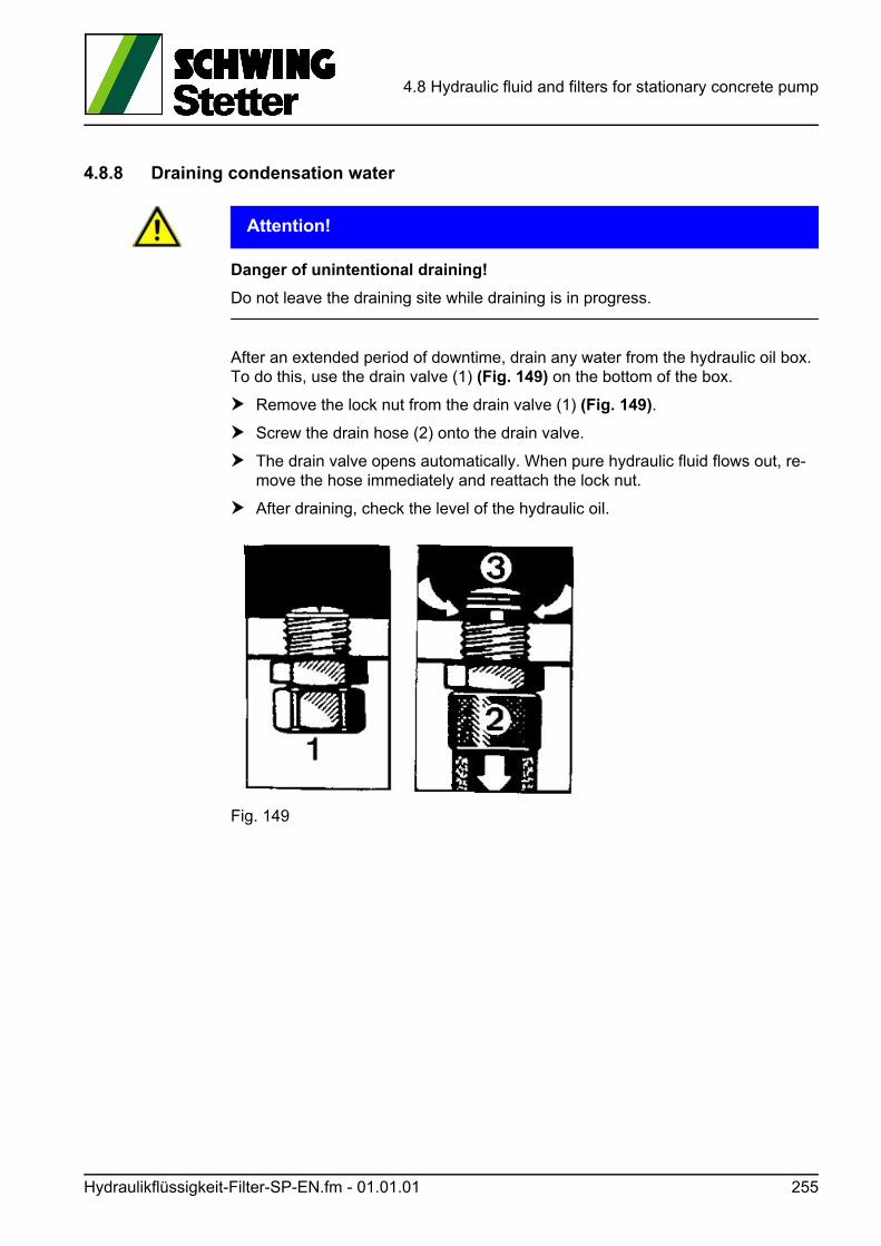
4.8 Hydraulic fluid and filters for stationary concrete pump
4.8.8 Draining condensation water
ACHTUNG! Attention!
Danger of unintentional draining!
Do not leave the draining site while draining is in progress.
After an extended period of downtime, drain any water from the hydraulic oil box. To do this, use the drain valve (1) (Fig. 149) on the bottom of the box.
Remove the lock nut from the drain valve (1) (Fig. 149).
Screw the drain hose (2) onto the drain valve.
The drain valve opens automatically. When pure hydraulic fluid flows out, re-move the hose immediately and reattach the lock nut.
After draining, check the level of the hydraulic oil.
Fig. 149
Hydraulikflüssigkeit-Filter-SP-EN.fm - 01.01.01 255
4.8 Hydraulic fluid and filters for stationary concrete pump
4.8.9 Changing the hydraulic fluid
Warm the hydraulic system up.
Provide a waste oil receptacle.
Due to the large quantity to be changed, you should first pump out as much fluid as possible through the upper cleaning opening. We recommend using our flushing and filtration unit for this.
Drain residual oil using the drain valve as described above.
Clean the box and replace the filter inserts whenever you change the oil.
Document the oil and filter changes using the appropriate SCHWING tags, see (Fig. 153) and (Fig. 154).
4.8.10 Cleaning the reservoir
In particular during long periods at standstill, the hydraulic oil excretes dirt particles which are deposited onto the bottom of the container.
Therefore, during each oil change, check the inner walls and the inner floor.
GEFAHR! Danger!
Risk of explosion!
Do not use naked light!
Clean the oil reservoir as needed. In addition:
Clean the area surrounding the cleaning cover and remove the cleaning cover (5) (Fig. 146) / (Fig. 147).
Remove the suction hoses of the hydraulic pumps from the box and close them to prevent dirt from getting into the pumps.
ACHTUNG! Attention!
Pumps can be destroyed!
• Clean the inside with flushing oil and a lint-free cloth.
Textile fibres and solvents can damage the hydraulic system. For this reason, do not use steel wool, diesel oil, petrol, etc. for cleaning purposes.
Wipe the inner sides of the box using a dry cloth.
Check the seal and mount the cleaning cover.
256 Hydraulikflüssigkeit-Filter-SP-EN.fm - 01.01.01
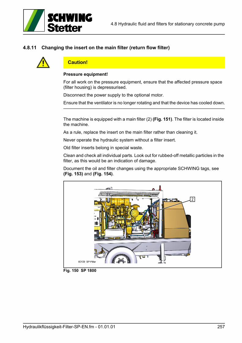
4.8 Hydraulic fluid and filters for stationary concrete pump
4.8.11 Changing the insert on the main filter (return flow filter)
VORSICHT! Caution!
Pressure equipment!
For all work on the pressure equipment, ensure that the affected pressure space (filter housing) is depressurised.
Disconnect the power supply to the optional motor.
Ensure that the ventilator is no longer rotating and that the device has cooled down.
The machine is equipped with a main filter (2) (Fig. 151). The filter is located inside the machine.
As a rule, replace the insert on the main filter rather than cleaning it.
Never operate the hydraulic system without a filter insert.
Old filter inserts belong in special waste.
Clean and check all individual parts. Look out for rubbed-off metallic particles in the filter, as this would be an indication of damage.
Document the oil and filter changes using the appropriate SCHWING tags, see (Fig. 153) and (Fig. 154).
Fig. 150 SP 1800
Hydraulikflüssigkeit-Filter-SP-EN.fm - 01.01.01 257
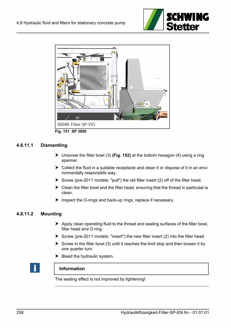
4.8 Hydraulic fluid and filters for stationary concrete pump
Fig. 151 SP 3800
4.8.11.1 Dismantling
Unscrew the filter bowl (3) (Fig. 152) at the bottom hexagon (4) using a ring spanner.
Collect the fluid in a suitable receptacle and clean it or dispose of it in an envi-ronmentally responsible way.
Screw (pre-2011 models: "pull") the old filter insert (2) off of the filter head.
Clean the filter bowl and the filter head, ensuring that the thread in particular is clean.
Inspect the O-rings and back-up rings, replace if necessary.
4.8.11.2 Mounting
Apply clean operating fluid to the thread and sealing surfaces of the filter bowl, filter head and O-ring.
Screw (pre-2011 models: "insert") the new filter insert (2) into the filter head.
Screw in the filter bowl (3) until it reaches the limit stop and then loosen it by one quarter turn.
Bleed the hydraulic system.
Information
The sealing effect is not improved by tightening!
258 Hydraulikflüssigkeit-Filter-SP-EN.fm - 01.01.01
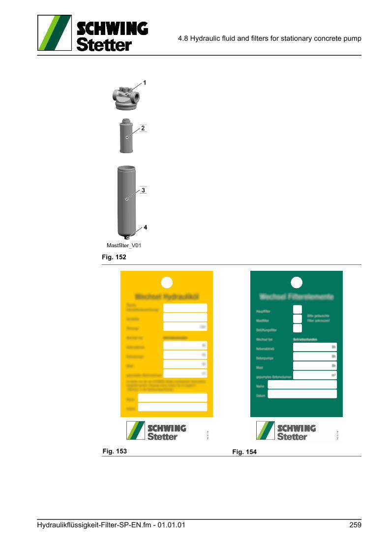
4.8 Hydraulic fluid and filters for stationary concrete pump
Fig. 152
Fig. 153 Fig. 154
Hydraulikflüssigkeit-Filter-SP-EN.fm - 01.01.01 259

4.8 Hydraulic fluid and filters for stationary concrete pump
260 Hydraulikflüssigkeit-Filter-SP-EN.fm - 01.01.01
4.9 Pressure checks - stationary concrete pumps
4.9 Pressure checks - stationary concrete pumps
All hydraulic consumers are secured by pressure relief valves (PRV).
These valves are set at the factory. Readjustment is as a rule only necessary after replacement or repair of the hydraulic systems.
Regular pressure checks serve to detect errors early on. Carry out the checks while the machine is running at operating temperature and speed.
WARNUNG! Warning!
The factory-set pressures must not be altered. Settings may only be config-ured by technically qualified workshop personnel!
• Only loosen hydraulic system connections if the drive is not running and the pressure accumulator (if present) is relieved. This also applies to the assembly and disassembly of test pressure gauges.
• After the pressure check, first switch off the concrete pump, then turn the ball valve. This is to prevent an uncontrolled start-up of the concrete pump.
ACHTUNG! Attention!
When checking the pressure of the concrete pump hydraulic system, be sure to set the direction to “Pump”.
In the direction "Sucking", the seals of the concrete pump control block may be pushed out.
4.9.1 Concrete pump system
The hydraulic pump of the concrete pump system is equipped with a "pressure cut-off". This swivels the pump back before the maximum operating pressure set on the pressure relief valve (PRV) is reached.
The pressure cut-off prevents the loss of performance and heating of oil which oc-cur when hydraulic oil is discharged from the pressure relief valve.
The value displayed on the pressure gauge during the pressure test must be lower than the setting on the pressure relief valve. See hydraulic switching diagram.
Appropriate settings are carried out on the hydraulic pump and pressure relief valve.
If, during the check, the prescribed values are clearly exceeded or fallen short of, leave the required setting adjustment work to SCHWING’s customer service.
Take the machine out of service and transmit the measured values to customer ser-vice.
Druckkontrolle-SP-EN.fm - 01.01.01 261
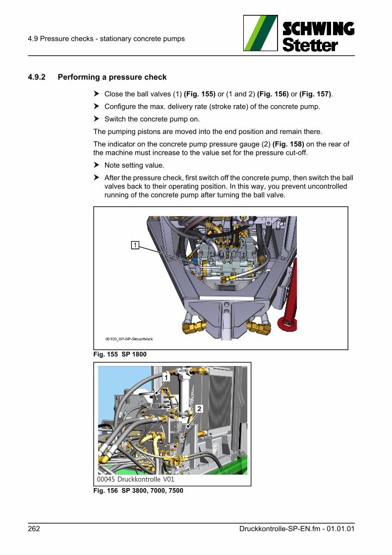
4.9 Pressure checks - stationary concrete pumps
4.9.2 Performing a pressure check
Close the ball valves (1) (Fig. 155) or (1 and 2) (Fig. 156) or (Fig. 157).
Configure the max. delivery rate (stroke rate) of the concrete pump.
Switch the concrete pump on.
The pumping pistons are moved into the end position and remain there.
The indicator on the concrete pump pressure gauge (2) (Fig. 158) on the rear of the machine must increase to the value set for the pressure cut-off.
Note setting value.
After the pressure check, first switch off the concrete pump, then switch the ball valves back to their operating position. In this way, you prevent uncontrolled running of the concrete pump after turning the ball valve.
Fig. 155 SP 1800
Fig. 156 SP 3800, 7000, 7500
262 Druckkontrolle-SP-EN.fm - 01.01.01
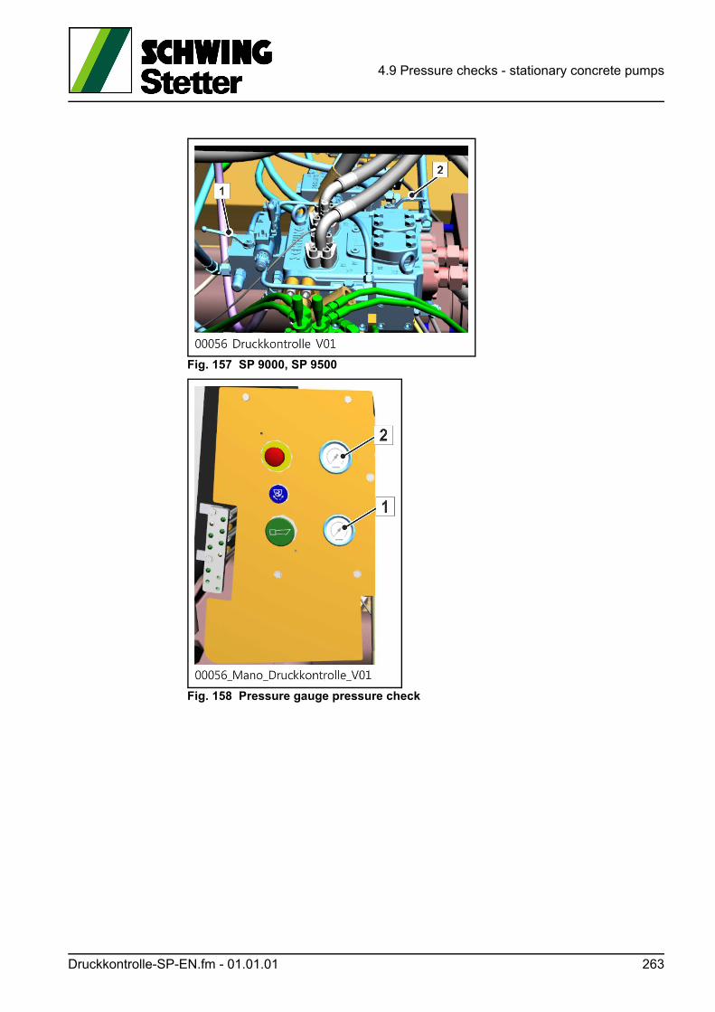
4.9 Pressure checks - stationary concrete pumps
Fig. 157 SP 9000, SP 9500
Fig. 158 Pressure gauge pressure check
Druckkontrolle-SP-EN.fm - 01.01.01 263

4.9 Pressure checks - stationary concrete pumps
264 Druckkontrolle-SP-EN.fm - 01.01.01
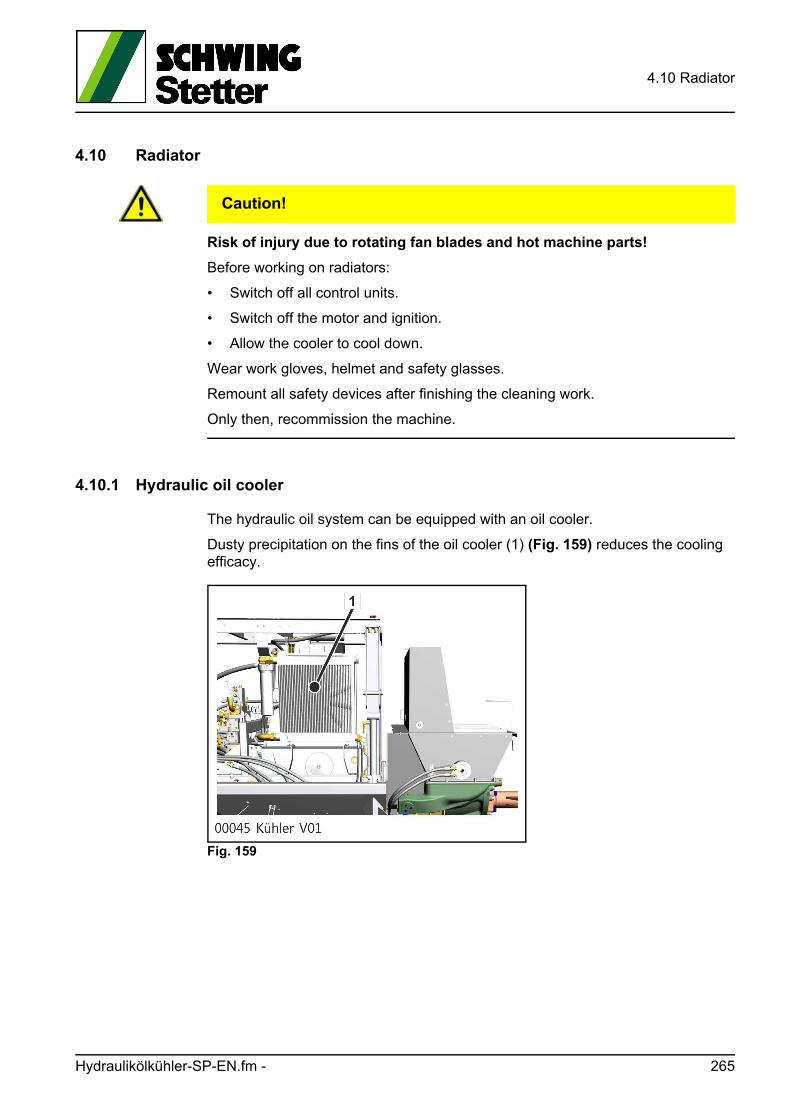
4.10 Radiator
4.10 Radiator
VORSICHT! Caution!
Risk of injury due to rotating fan blades and hot machine parts!
Before working on radiators:
• Switch off all control units.
• Switch off the motor and ignition.
• Allow the cooler to cool down.
Wear work gloves, helmet and safety glasses.
Remount all safety devices after finishing the cleaning work.
Only then, recommission the machine.
4.10.1 Hydraulic oil cooler
The hydraulic oil system can be equipped with an oil cooler.
Dusty precipitation on the fins of the oil cooler (1) (Fig. 159) reduces the cooling efficacy.
Fig. 159
Hydraulikölkühler-SP-EN.fm - 265
4.10 Radiator
4.10.1.1 Cleaning the exterior of the hydraulic oil cooler
Carefully clean the radiator with compressed air. To do this, bring the air flow par-allel to the cooler fins and against the normal flow direction.
Cleaning with water or steam jet is possible for heavy soiling.
ACHTUNG! Attention!
Steam jet cleaning can potentially cause damage!
Before steam jet cleaning:
• Disassemble fan motor.
• Only use cleaning agents that do not corrode aluminium.
• Use water and steam jets carefully.
4.10.1.2 Cleaning the inside of the hydraulic oil cooler
• Remove the cooler.
• Connect cooler to a flushing system with filters.
• Flush for at least 30 minutes.
• After cleaning, remove the flushing medium completely.
• Then, flush the cooler with an oil type intended for the hydraulic system.
4.10.2 Motor cooler
Liquid-cooled motors have an appropriate cooler.
Depending on the type, the drive motor can be additionally equipped with a motor oil cooler.
Please make sure, when working on dusty jobsites, that the cooling fins of the mo-tor cooler are cleaned from time to time.
Otherwise, this can result in damage due to the motor overheating.
Instructions on how to clean the cooler can be found in the respective motor or ve-hicle operating instructions.
266 Hydraulikölkühler-SP-EN.fm - 01.00.00
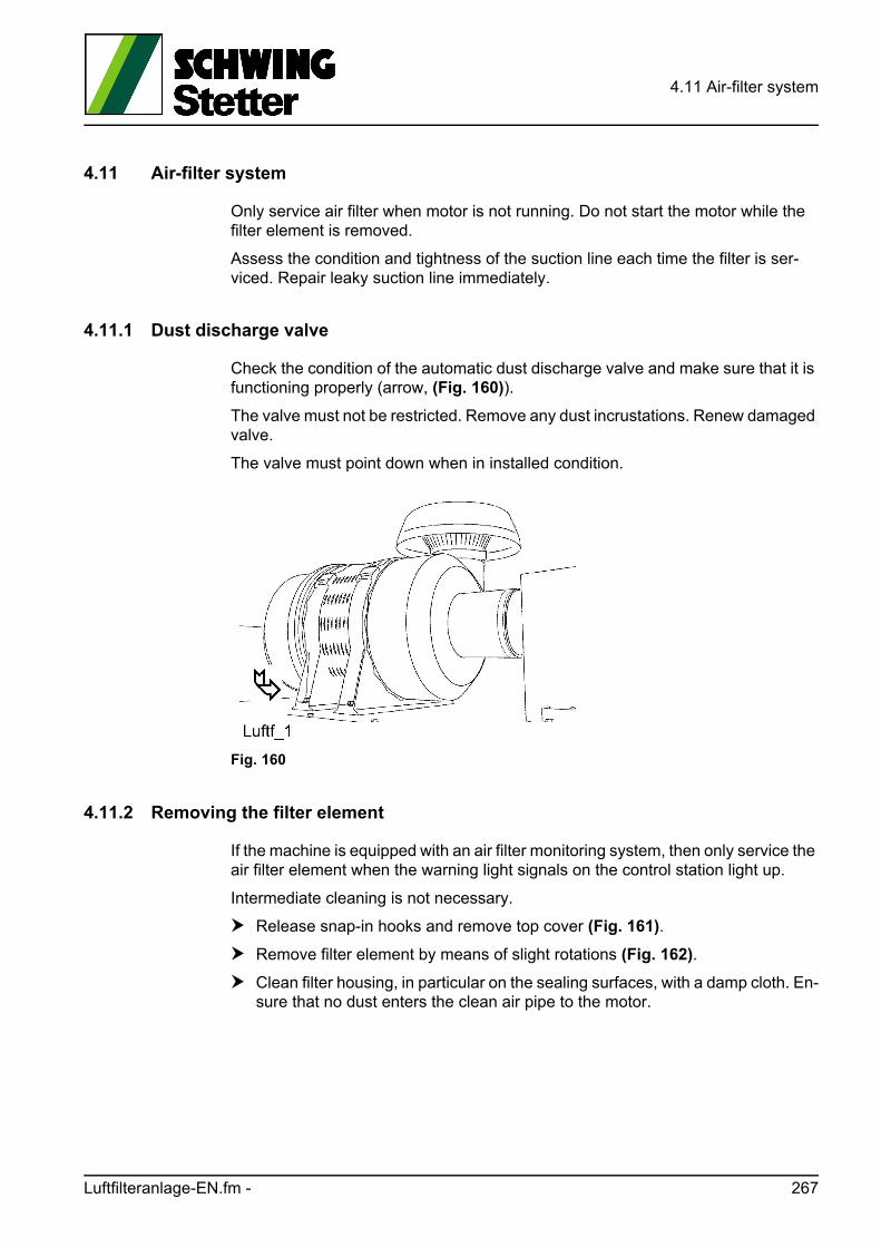
4.11 Air-filter system
4.11 Air-filter system
Only service air filter when motor is not running. Do not start the motor while the filter element is removed.
Assess the condition and tightness of the suction line each time the filter is ser-viced. Repair leaky suction line immediately.
4.11.1 Dust discharge valve
Check the condition of the automatic dust discharge valve and make sure that it is functioning properly (arrow, (Fig. 160)).
The valve must not be restricted. Remove any dust incrustations. Renew damaged valve.
The valve must point down when in installed condition.
Fig. 160
4.11.2 Removing the filter element
If the machine is equipped with an air filter monitoring system, then only service the air filter element when the warning light signals on the control station light up.
Intermediate cleaning is not necessary.
Release snap-in hooks and remove top cover (Fig. 161).
Remove filter element by means of slight rotations (Fig. 162).
Clean filter housing, in particular on the sealing surfaces, with a damp cloth. En-sure that no dust enters the clean air pipe to the motor.
Luftfilteranlage-EN.fm - 267

4.11 Air-filter system
Fig. 161
Fig. 162
4.11.3 Cleaning the filter element
Replace the filter element after 3 cleanings or after one year at the latest.
ACHTUNG! Attention!
Improper cleaning!
Never wash or brush filter element or clean by slamming.
Clean and dry compressed air is used for the cleaning (max. 5 bar). Dust may not get to the inside of the element when blowing out dust.
A tube whose end is bent by approx. 90° should be placed onto the compressed air gun. It must extend to the bottom of the element (Fig. 163).
Blow out the element from the inside out by moving the pipe up and down until dust no longer emerges (Fig. 164). Do not damage the filter element!
268 Luftfilteranlage-EN.fm -
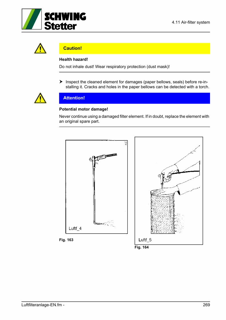
4.11 Air-filter system
VORSICHT! Caution!
Health hazard!
Do not inhale dust! Wear respiratory protection (dust mask)!
Inspect the cleaned element for damages (paper bellows, seals) before re-in-stalling it. Cracks and holes in the paper bellows can be detected with a torch.
ACHTUNG! Attention!
Potential motor damage!
Never continue using a damaged filter element. If in doubt, replace the element with an original spare part.
Fig. 163
Fig. 164
Luftfilteranlage-EN.fm - 269

4.11 Air-filter system
4.11.4 Installing the filter element
Insert filter element carefully into the housing.
Mount cover of housing. Ensure that the dust discharge valve faces down-wards. When closing the top cover, the filter element is automatically pressed into the correct position.
4.11.5 Storage
Store the filter element upright in the original packaging and protected from dust, moisture and damage.
4.11.6 Disposal
The filter element consists of filter paper and polyurethane foam.
All filter elements are hazardous waste and must be disposed of according to the local provisions.
4.11.7 Function testing of maintenance indicator
Reduce the suction intake of the air-filter system (e.g. with a stable plate or cardboard) while the motor idles until the maintenance indicator reacts.
ACHTUNG! Attention!
Motor damage!
Do not, by any means, close the suction intake completely!
270 Luftfilteranlage-EN.fm - 01.00.00
4.12 Rock valve
4.12 Rock valve
GEFAHR! Danger!
Danger of crushing and injury!
To prevent unwanted working movements prior to working on the rock valve, al-ways follow the points below!
• Switch off the drive motor and prevent it from starting up.
• Switch off concrete pump and agitator.
• Do not reach into the gate valve while the drive motor is running.
• Discharge the pressure accumulator, if applicable.
4.12.1 Lubricating the bearing points
Concrete pumps without central greasing have a central greasing strip, see exam-ples (Fig. 165 Greasing strip on stationary concrete pumps) and (Fig. 166 Greasing strip on truck-mounted concrete pumps).
The grease nipples on this strip are connected to the bearing points of the rock valve.
Bearing points include:
• Slewing shaft
• Slewing cylinder
• Agitator
Depending on the type of rock valve, the number of grease nipples can vary. Addi-tional grease nipples are located on the greasing strip for the mixer bearing in truck mixer concrete pumps.
Lubricate all grease nipples daily on the greasing strip. Lubricate more frequently during continuous operation, at least every 8 hours:
Lubrication procedure:
Clean the lubrication point.
Remove the protection caps from the grease nipples.
Press grease into each grease nipple until the old grease emerges from the bearing point.
Wipe off old grease with cleaning rags. Dispose of grease and cleaning rags properly.
Reattach the protection caps.
Rockschieber-EN.fm - 01.17.01 271
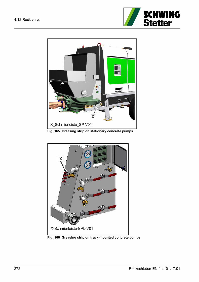
4.12 Rock valve
Fig. 165 Greasing strip on stationary concrete pumps
Fig. 166 Greasing strip on truck-mounted concrete pumps
272 Rockschieber-EN.fm - 01.17.01
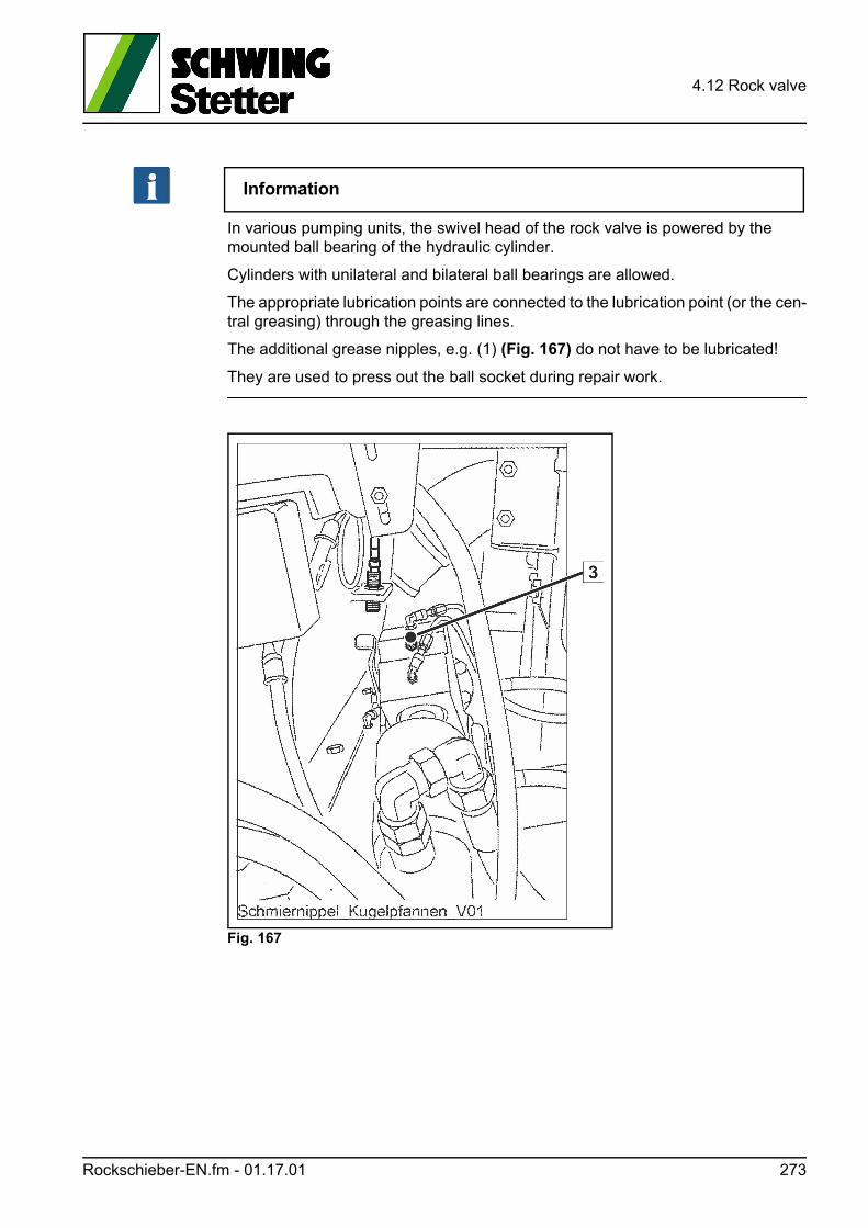
4.12 Rock valve
Information
In various pumping units, the swivel head of the rock valve is powered by the mounted ball bearing of the hydraulic cylinder.
Cylinders with unilateral and bilateral ball bearings are allowed.
The appropriate lubrication points are connected to the lubrication point (or the cen-tral greasing) through the greasing lines.
The additional grease nipples, e.g. (1) (Fig. 167) do not have to be lubricated!
They are used to press out the ball socket during repair work.
Fig. 167
Rockschieber-EN.fm - 01.17.01 273
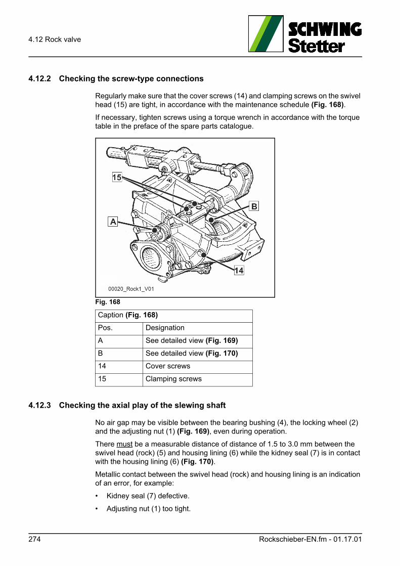
4.12 Rock valve
4.12.2 Checking the screw-type connections
Regularly make sure that the cover screws (14) and clamping screws on the swivel head (15) are tight, in accordance with the maintenance schedule (Fig. 168).
If necessary, tighten screws using a torque wrench in accordance with the torque table in the preface of the spare parts catalogue.
Fig. 168
4.12.3 Checking the axial play of the slewing shaft
No air gap may be visible between the bearing bushing (4), the locking wheel (2) and the adjusting nut (1) (Fig. 169), even during operation.
There must be a measurable distance of distance of 1.5 to 3.0 mm between the swivel head (rock) (5) and housing lining (6) while the kidney seal (7) is in contact with the housing lining (6) (Fig. 170).
Metallic contact between the swivel head (rock) and housing lining is an indication of an error, for example:
• Kidney seal (7) defective.
• Adjusting nut (1) too tight.
Caption (Fig. 168)
Pos. Designation
A See detailed view (Fig. 169)
B See detailed view (Fig. 170)
14 Cover screws
15 Clamping screws
274 Rockschieber-EN.fm - 01.17.01
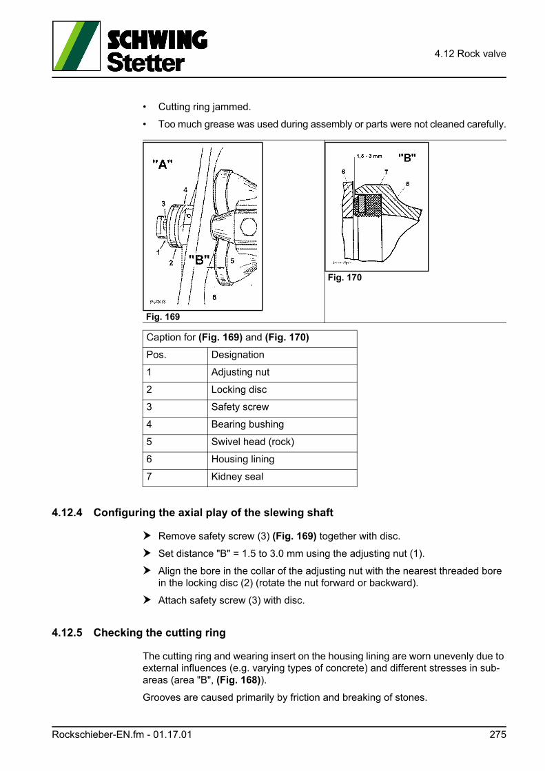
4.12 Rock valve
• Cutting ring jammed.
• Too much grease was used during assembly or parts were not cleaned carefully.
4.12.4 Configuring the axial play of the slewing shaft
Remove safety screw (3) (Fig. 169) together with disc.
Set distance "B" = 1.5 to 3.0 mm using the adjusting nut (1).
Align the bore in the collar of the adjusting nut with the nearest threaded bore in the locking disc (2) (rotate the nut forward or backward).
Attach safety screw (3) with disc.
4.12.5 Checking the cutting ring
The cutting ring and wearing insert on the housing lining are worn unevenly due to external influences (e.g. varying types of concrete) and different stresses in sub-areas (area "B", (Fig. 168)).
Grooves are caused primarily by friction and breaking of stones.
Fig. 169
Fig. 170
Caption for (Fig. 169) and (Fig. 170)
Pos. Designation
1 Adjusting nut
2 Locking disc
3 Safety screw
4 Bearing bushing
5 Swivel head (rock)
6 Housing lining
7 Kidney seal
Rockschieber-EN.fm - 01.17.01 275
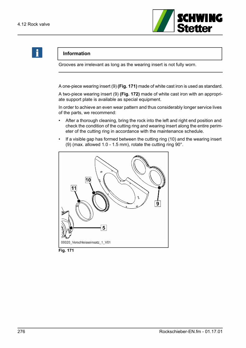
4.12 Rock valve
Information
Grooves are irrelevant as long as the wearing insert is not fully worn.
A one-piece wearing insert (9) (Fig. 171) made of white cast iron is used as standard.
A two-piece wearing insert (9) (Fig. 172) made of white cast iron with an appropri-ate support plate is available as special equipment.
In order to achieve an even wear pattern and thus considerably longer service lives of the parts, we recommend:
• After a thorough cleaning, bring the rock into the left and right end position and check the condition of the cutting ring and wearing insert along the entire perim-eter of the cutting ring in accordance with the maintenance schedule.
• If a visible gap has formed between the cutting ring (10) and the wearing insert (9) (max. allowed 1.0 - 1.5 mm), rotate the cutting ring 90°.
Fig. 171
276 Rockschieber-EN.fm - 01.17.01
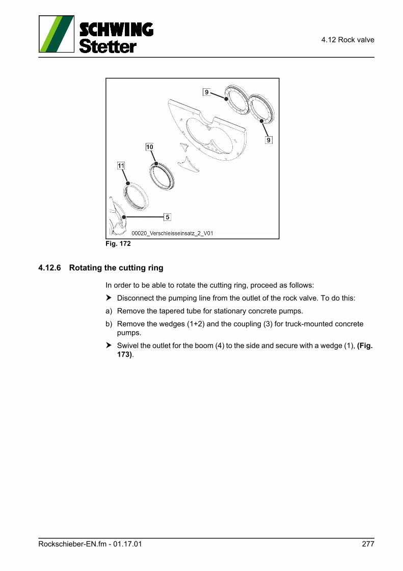
4.12 Rock valve
Fig. 172
4.12.6 Rotating the cutting ring
In order to be able to rotate the cutting ring, proceed as follows:
Disconnect the pumping line from the outlet of the rock valve. To do this:
a) Remove the tapered tube for stationary concrete pumps.
b) Remove the wedges (1+2) and the coupling (3) for truck-mounted concrete pumps.
Swivel the outlet for the boom (4) to the side and secure with a wedge (1), (Fig. 173).
Rockschieber-EN.fm - 01.17.01 277
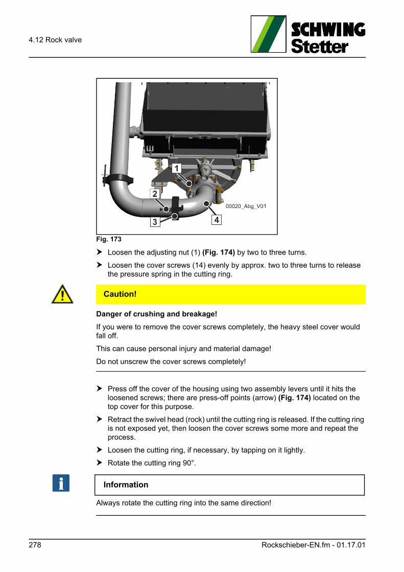
4.12 Rock valve
Fig. 173
Loosen the adjusting nut (1) (Fig. 174) by two to three turns.
Loosen the cover screws (14) evenly by approx. two to three turns to release the pressure spring in the cutting ring.
VORSICHT! Caution!
Danger of crushing and breakage!
If you were to remove the cover screws completely, the heavy steel cover would fall off.
This can cause personal injury and material damage!
Do not unscrew the cover screws completely!
Press off the cover of the housing using two assembly levers until it hits the loosened screws; there are press-off points (arrow) (Fig. 174) located on the top cover for this purpose.
Retract the swivel head (rock) until the cutting ring is released. If the cutting ring is not exposed yet, then loosen the cover screws some more and repeat the process.
Loosen the cutting ring, if necessary, by tapping on it lightly.
Rotate the cutting ring 90°.
Information
Always rotate the cutting ring into the same direction!
278 Rockschieber-EN.fm - 01.17.01
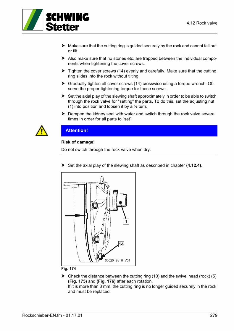
4.12 Rock valve
Make sure that the cutting ring is guided securely by the rock and cannot fall out or tilt.
Also make sure that no stones etc. are trapped between the individual compo-nents when tightening the cover screws.
Tighten the cover screws (14) evenly and carefully. Make sure that the cutting ring slides into the rock without tilting.
Gradually tighten all cover screws (14) crosswise using a torque wrench. Ob-serve the proper tightening torque for these screws.
Set the axial play of the slewing shaft approximately in order to be able to switch through the rock valve for "setting" the parts. To do this, set the adjusting nut (1) into position and loosen it by a ½ turn.
Dampen the kidney seal with water and switch through the rock valve several times in order for all parts to “set”.
ACHTUNG! Attention!
Risk of damage!
Do not switch through the rock valve when dry.
Set the axial play of the slewing shaft as described in chapter (4.12.4).
Fig. 174
Check the distance between the cutting ring (10) and the swivel head (rock) (5) (Fig. 175) and (Fig. 176) after each rotation. If it is more than 8 mm, the cutting ring is no longer guided securely in the rock and must be replaced.
Rockschieber-EN.fm - 01.17.01 279
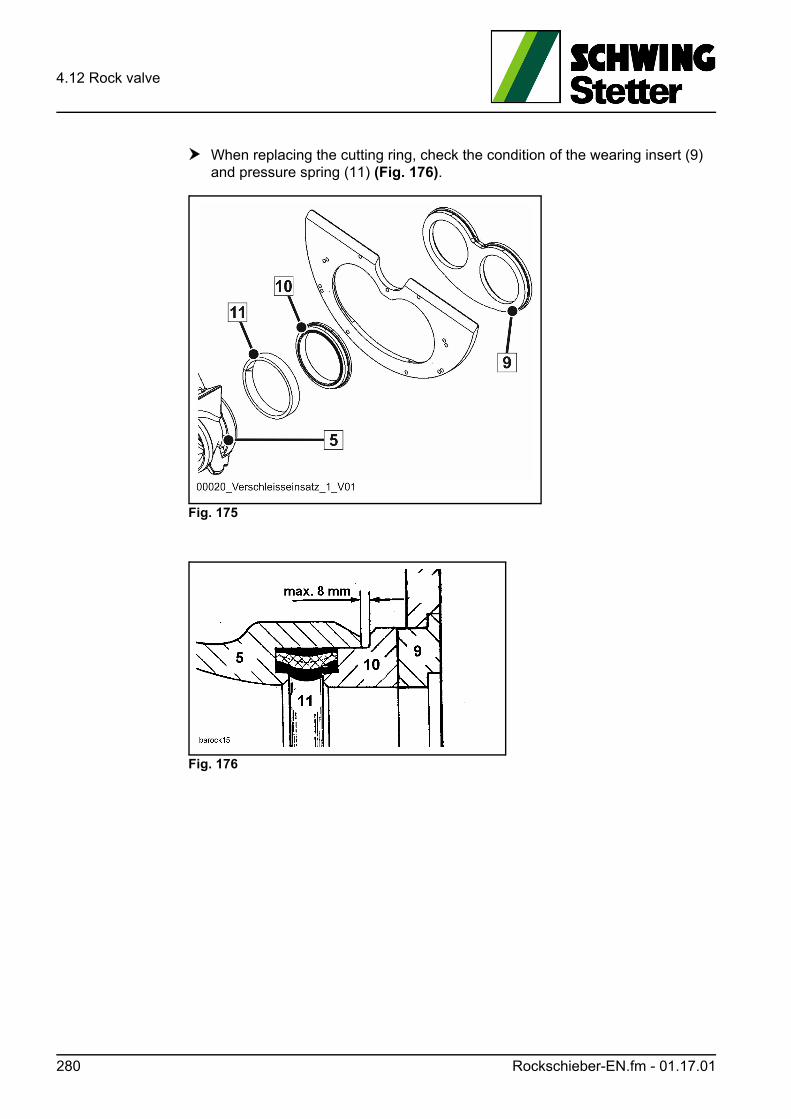
4.12 Rock valve
When replacing the cutting ring, check the condition of the wearing insert (9) and pressure spring (11) (Fig. 176).
Fig. 175
Fig. 176
280 Rockschieber-EN.fm - 01.17.01
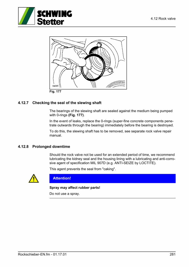
4.12 Rock valve
Fig. 177
4.12.7 Checking the seal of the slewing shaft
The bearings of the slewing shaft are sealed against the medium being pumped with 0-rings (Fig. 177).
In the event of leaks, replace the 0-rings (super-fine concrete components pene-trate outwards through the bearing) immediately before the bearing is destroyed.
To do this, the slewing shaft has to be removed, see separate rock valve repair manual.
4.12.8 Prolonged downtime
Should the rock valve not be used for an extended period of time, we recommend lubricating the kidney seal and the housing lining with a lubricating and anti-corro-sive agent of specification MIL 907D (e.g. ANTI-SEIZE by LOCTITE).
This agent prevents the seal from "caking".
ACHTUNG! Attention!
Spray may affect rubber parts!
Do not use a spray.
Rockschieber-EN.fm - 01.17.01 281
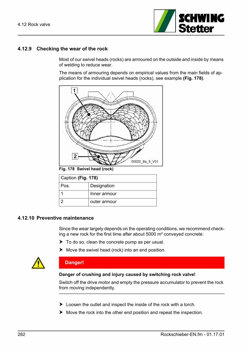
4.12 Rock valve
4.12.9 Checking the wear of the rock
Most of our swivel heads (rocks) are armoured on the outside and inside by means of welding to reduce wear.
The means of armouring depends on empirical values from the main fields of ap-plication for the individual swivel heads (rocks), see example (Fig. 178).
Fig. 178 Swivel head (rock)
4.12.10 Preventive maintenance
Since the wear largely depends on the operating conditions, we recommend check-ing a new rock for the first time after about 5000 m³ conveyed concrete:
To do so, clean the concrete pump as per usual.
Move the swivel head (rock) into an end position.
GEFAHR! Danger!
Danger of crushing and injury caused by switching rock valve!
Switch off the drive motor and empty the pressure accumulator to prevent the rock from moving independently.
Loosen the outlet and inspect the inside of the rock with a torch.
Move the rock into the other end position and repeat the inspection.
Caption (Fig. 178)
Pos. Designation
1 Inner armour
2 outer armour
282 Rockschieber-EN.fm - 01.17.01
4.12 Rock valve
Further inspection intervals can now be determined depending on the condition.
The swivel head (rock) must be replaced if the basic material "shows through" at certain points.
The inner armouring usually wears faster than the outer armouring.
The exterior should be checked as soon as significant wear is detected on the inside.
Information
A regeneration by means of renewed hard facing is no longer possible for the ma-terials currently used!
We strongly advise against unqualified welding and the use of replicas.
SCHWING is not liable for damages caused by improper repair attempts or replicas.
Rockschieber-EN.fm - 01.17.01 283

4.12 Rock valve
284 Rockschieber-EN.fm - 01.17.01
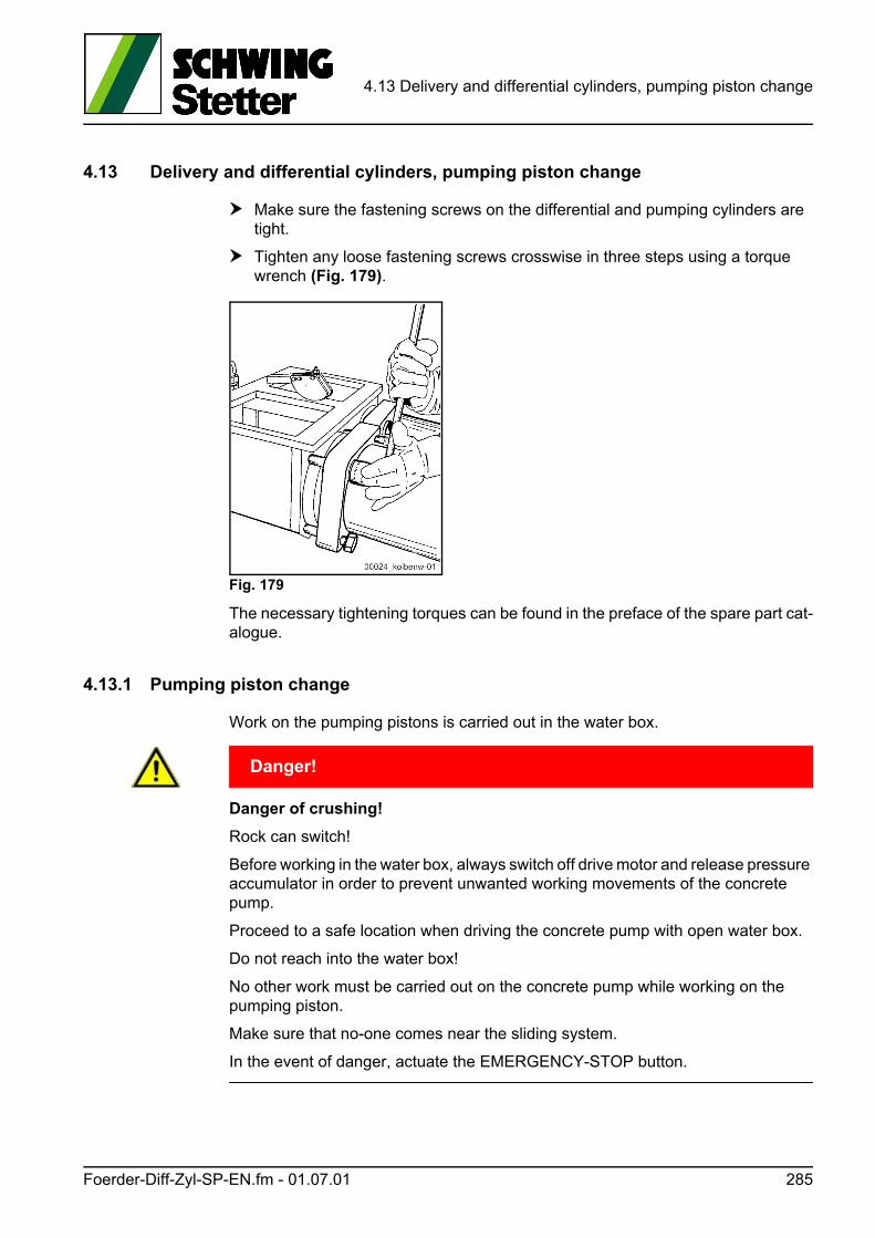
4.13 Delivery and differential cylinders, pumping piston change
4.13 Delivery and differential cylinders, pumping piston change
Make sure the fastening screws on the differential and pumping cylinders are tight.
Tighten any loose fastening screws crosswise in three steps using a torque wrench (Fig. 179).
Fig. 179
The necessary tightening torques can be found in the preface of the spare part cat-alogue.
4.13.1 Pumping piston change
Work on the pumping pistons is carried out in the water box.
GEFAHR! Danger!
Danger of crushing!
Rock can switch!
Before working in the water box, always switch off drive motor and release pressure accumulator in order to prevent unwanted working movements of the concrete pump.
Proceed to a safe location when driving the concrete pump with open water box.
Do not reach into the water box!
No other work must be carried out on the concrete pump while working on the pumping piston.
Make sure that no-one comes near the sliding system.
In the event of danger, actuate the EMERGENCY-STOP button.
Foerder-Diff-Zyl-SP-EN.fm - 01.07.01 285
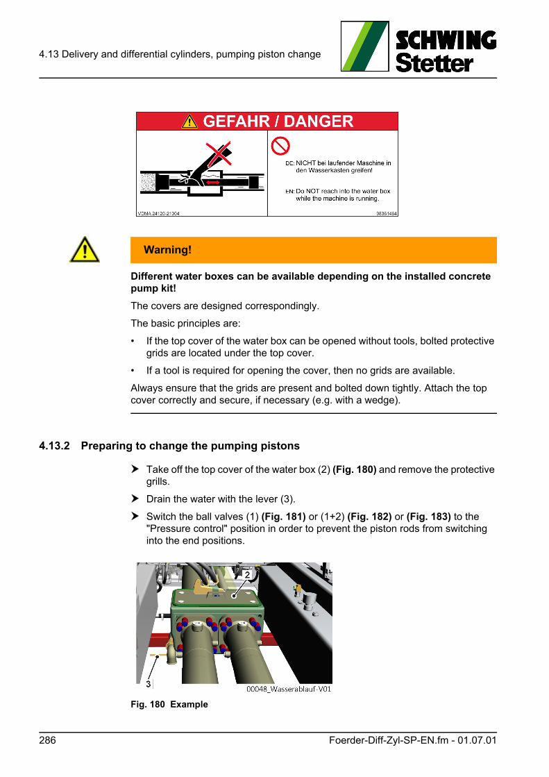
4.13 Delivery and differential cylinders, pumping piston change
WARNUNG! Warning!
Different water boxes can be available depending on the installed concrete pump kit!
The covers are designed correspondingly.
The basic principles are:
• If the top cover of the water box can be opened without tools, bolted protective grids are located under the top cover.
• If a tool is required for opening the cover, then no grids are available.
Always ensure that the grids are present and bolted down tightly. Attach the top cover correctly and secure, if necessary (e.g. with a wedge).
4.13.2 Preparing to change the pumping pistons
Take off the top cover of the water box (2) (Fig. 180) and remove the protective grills.
Drain the water with the lever (3).
Switch the ball valves (1) (Fig. 181) or (1+2) (Fig. 182) or (Fig. 183) to the "Pressure control" position in order to prevent the piston rods from switching into the end positions.
Fig. 180 Example
286 Foerder-Diff-Zyl-SP-EN.fm - 01.07.01
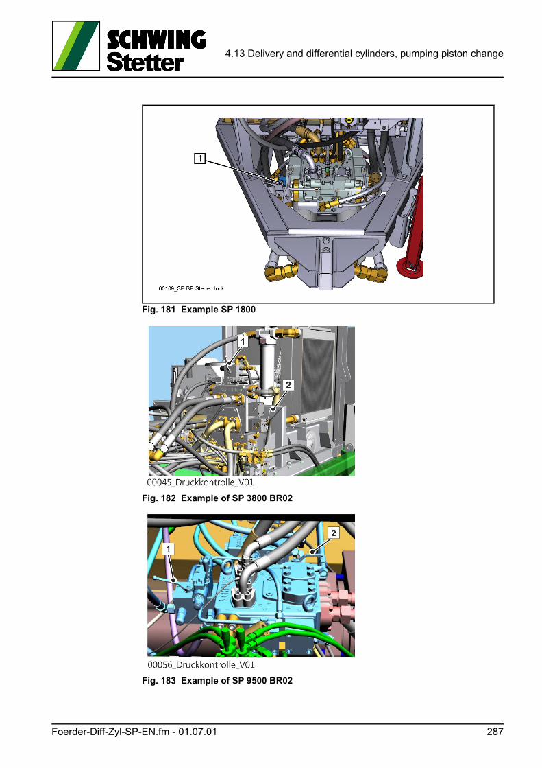
4.13 Delivery and differential cylinders, pumping piston change
Fig. 181 Example SP 1800
Fig. 182 Example of SP 3800 BR02
Fig. 183 Example of SP 9500 BR02
Foerder-Diff-Zyl-SP-EN.fm - 01.07.01 287
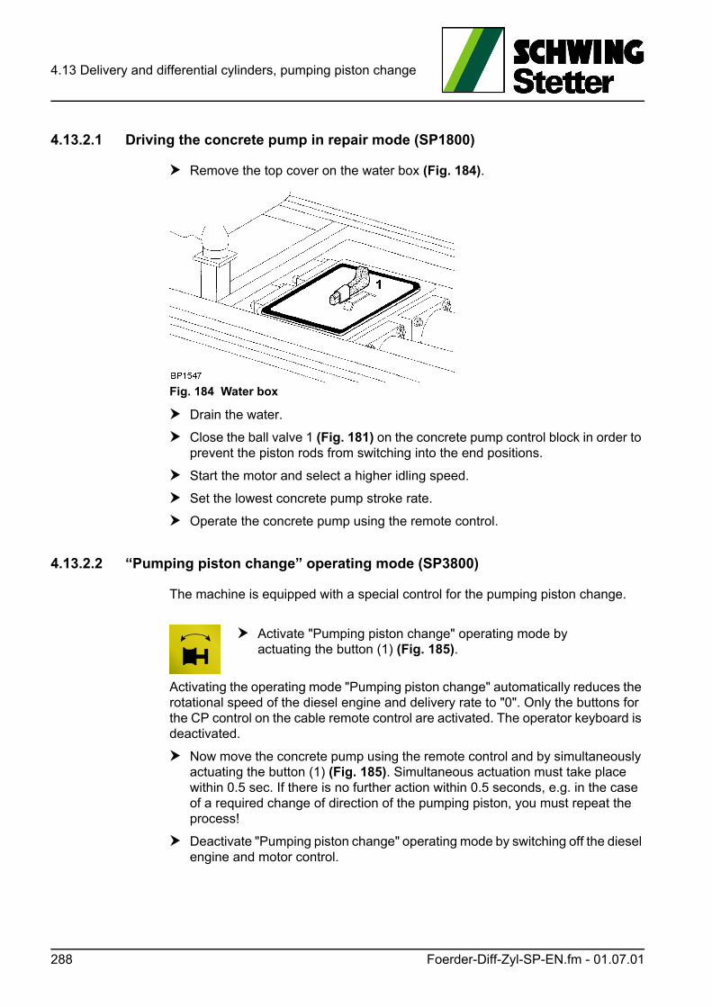
4.13 Delivery and differential cylinders, pumping piston change
4.13.2.1 Driving the concrete pump in repair mode (SP1800)
Remove the top cover on the water box (Fig. 184).
Fig. 184 Water box
Drain the water.
Close the ball valve 1 (Fig. 181) on the concrete pump control block in order to prevent the piston rods from switching into the end positions.
Start the motor and select a higher idling speed.
Set the lowest concrete pump stroke rate.
Operate the concrete pump using the remote control.
4.13.2.2 “Pumping piston change” operating mode (SP3800)
The machine is equipped with a special control for the pumping piston change.
Activating the operating mode "Pumping piston change" automatically reduces the rotational speed of the diesel engine and delivery rate to "0". Only the buttons for the CP control on the cable remote control are activated. The operator keyboard is deactivated.
Now move the concrete pump using the remote control and by simultaneously actuating the button (1) (Fig. 185). Simultaneous actuation must take place within 0.5 sec. If there is no further action within 0.5 seconds, e.g. in the case of a required change of direction of the pumping piston, you must repeat the process!
Deactivate "Pumping piston change" operating mode by switching off the diesel engine and motor control.
Activate "Pumping piston change" operating mode by actuating the button (1) (Fig. 185).
288 Foerder-Diff-Zyl-SP-EN.fm - 01.07.01
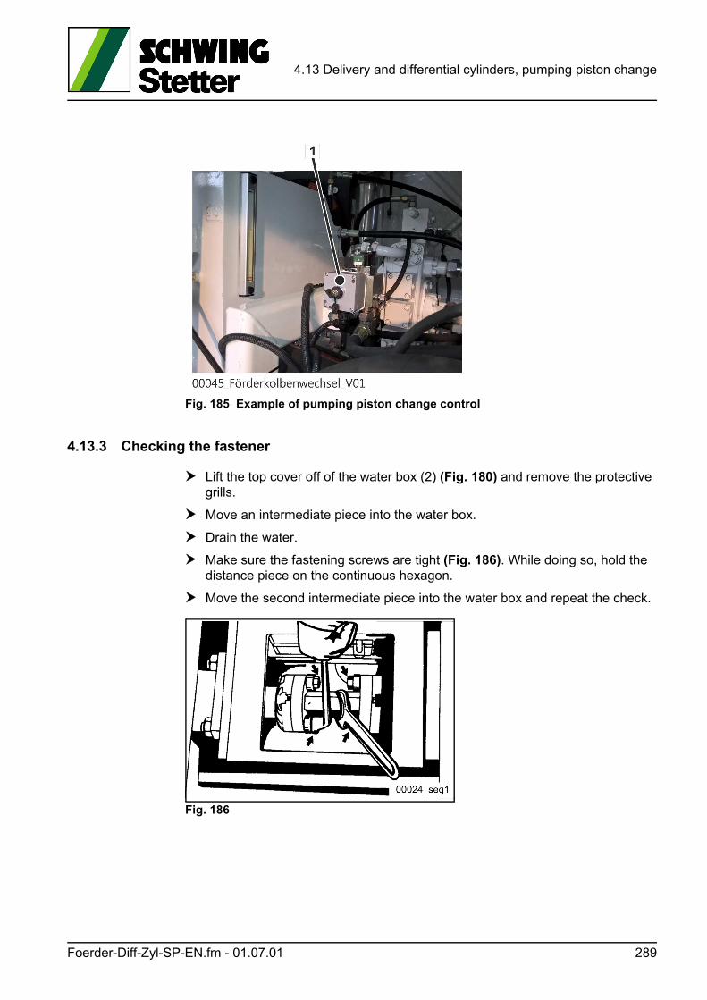
4.13 Delivery and differential cylinders, pumping piston change
Fig. 185 Example of pumping piston change control
4.13.3 Checking the fastener
Lift the top cover off of the water box (2) (Fig. 180) and remove the protective grills.
Move an intermediate piece into the water box.
Drain the water.
Make sure the fastening screws are tight (Fig. 186). While doing so, hold the distance piece on the continuous hexagon.
Move the second intermediate piece into the water box and repeat the check.
Fig. 186
Foerder-Diff-Zyl-SP-EN.fm - 01.07.01 289
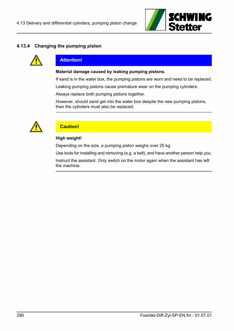
4.13 Delivery and differential cylinders, pumping piston change
4.13.4 Changing the pumping piston
ACHTUNG! Attention!
Material damage caused by leaking pumping pistons.
If sand is in the water box, the pumping pistons are worn and need to be replaced.
Leaking pumping pistons cause premature wear on the pumping cylinders.
Always replace both pumping pistons together.
However, should sand get into the water box despite the new pumping pistons, then the cylinders must also be replaced.
VORSICHT! Caution!
High weight!
Depending on the size, a pumping piston weighs over 25 kg.
Use tools for installing and removing (e.g. a belt), and have another person help you.
Instruct the assistant. Only switch on the motor again when the assistant has left the machine.
290 Foerder-Diff-Zyl-SP-EN.fm - 01.07.01
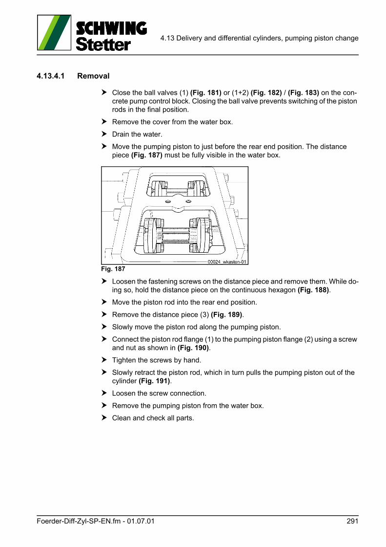
4.13 Delivery and differential cylinders, pumping piston change
4.13.4.1 Removal
Close the ball valves (1) (Fig. 181) or (1+2) (Fig. 182) / (Fig. 183) on the con-crete pump control block. Closing the ball valve prevents switching of the piston rods in the final position.
Remove the cover from the water box.
Drain the water.
Move the pumping piston to just before the rear end position. The distance piece (Fig. 187) must be fully visible in the water box.
Fig. 187
Loosen the fastening screws on the distance piece and remove them. While do-ing so, hold the distance piece on the continuous hexagon (Fig. 188).
Move the piston rod into the rear end position.
Remove the distance piece (3) (Fig. 189).
Slowly move the piston rod along the pumping piston.
Connect the piston rod flange (1) to the pumping piston flange (2) using a screw and nut as shown in (Fig. 190).
Tighten the screws by hand.
Slowly retract the piston rod, which in turn pulls the pumping piston out of the cylinder (Fig. 191).
Loosen the screw connection.
Remove the pumping piston from the water box.
Clean and check all parts.
Foerder-Diff-Zyl-SP-EN.fm - 01.07.01 291
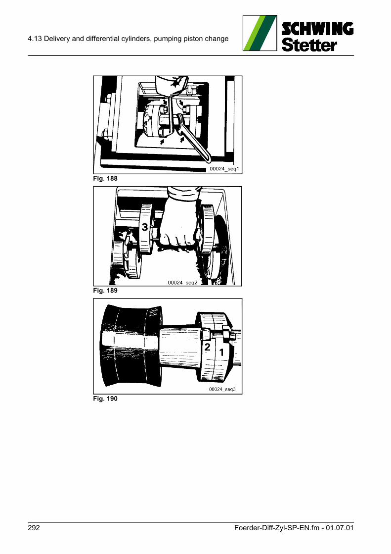
4.13 Delivery and differential cylinders, pumping piston change
Fig. 188
Fig. 189
Fig. 190
292 Foerder-Diff-Zyl-SP-EN.fm - 01.07.01
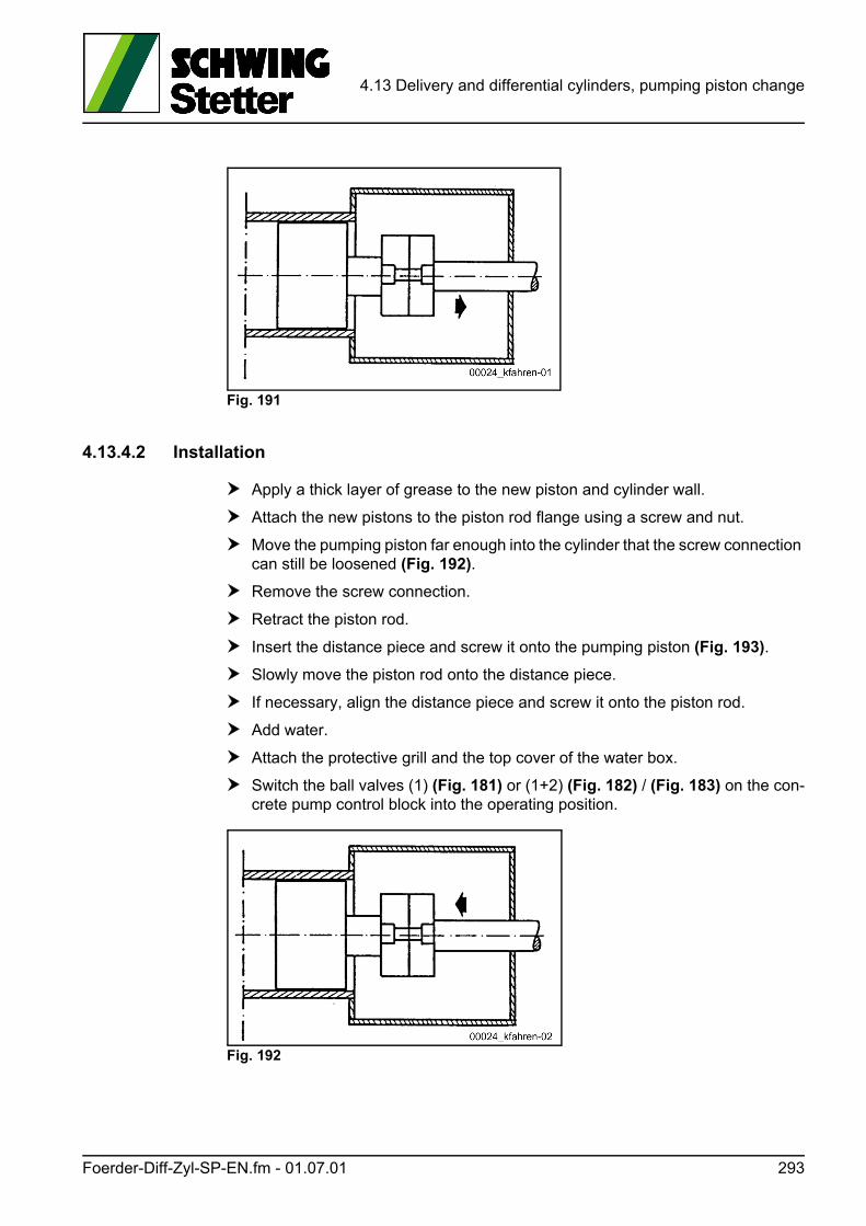
4.13 Delivery and differential cylinders, pumping piston change
Fig. 191
4.13.4.2 Installation
Apply a thick layer of grease to the new piston and cylinder wall.
Attach the new pistons to the piston rod flange using a screw and nut.
Move the pumping piston far enough into the cylinder that the screw connection can still be loosened (Fig. 192).
Remove the screw connection.
Retract the piston rod.
Insert the distance piece and screw it onto the pumping piston (Fig. 193).
Slowly move the piston rod onto the distance piece.
If necessary, align the distance piece and screw it onto the piston rod.
Add water.
Attach the protective grill and the top cover of the water box.
Switch the ball valves (1) (Fig. 181) or (1+2) (Fig. 182) / (Fig. 183) on the con-crete pump control block into the operating position.
Fig. 192
Foerder-Diff-Zyl-SP-EN.fm - 01.07.01 293
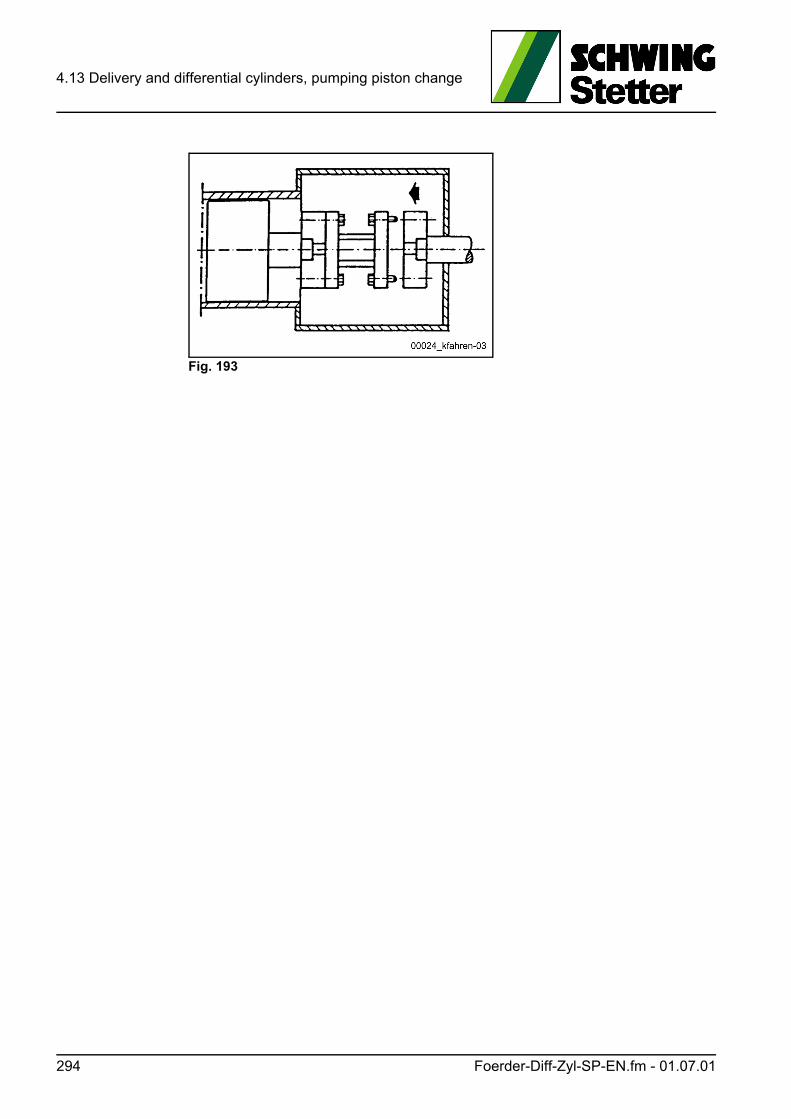
4.13 Delivery and differential cylinders, pumping piston change
Fig. 193
294 Foerder-Diff-Zyl-SP-EN.fm - 01.07.01
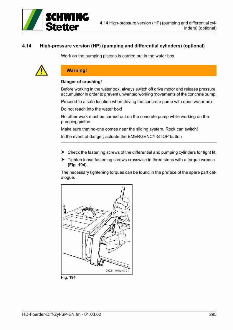
4.14 High-pressure version (HP) (pumping and differential cyl-inders) (optional)
4.14 High-pressure version (HP) (pumping and differential cylinders) (optional)
Work on the pumping pistons is carried out in the water box.
WARNUNG! Warning!
Danger of crushing!
Before working in the water box, always switch off drive motor and release pressure accumulator in order to prevent unwanted working movements of the concrete pump.
Proceed to a safe location when driving the concrete pump with open water box.
Do not reach into the water box!
No other work must be carried out on the concrete pump while working on the pumping piston.
Make sure that no-one comes near the sliding system. Rock can switch!
In the event of danger, actuate the EMERGENCY-STOP button
Check the fastening screws of the differential and pumping cylinders for tight fit.
Tighten loose fastening screws crosswise in three steps with a torque wrench (Fig. 194).
The necessary tightening torques can be found in the preface of the spare part cat-alogue.
Fig. 194
HD-Foerder-Diff-Zyl-SP-EN.fm - 01.03.02 295
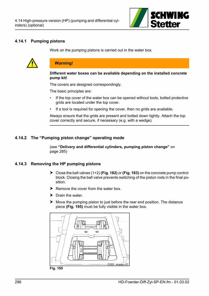
4.14 High-pressure version (HP) (pumping and differential cyl-inders) (optional)
4.14.1 Pumping pistons
Work on the pumping pistons is carried out in the water box.
WARNUNG! Warning!
Different water boxes can be available depending on the installed concrete pump kit!
The covers are designed correspondingly.
The basic principles are:
• If the top cover of the water box can be opened without tools, bolted protective grids are located under the top cover.
• If a tool is required for opening the cover, then no grids are available.
Always ensure that the grids are present and bolted down tightly. Attach the top cover correctly and secure, if necessary (e.g. with a wedge).
4.14.2 The “Pumping piston change” operating mode
(see “Delivery and differential cylinders, pumping piston change” on page 285)
4.14.3 Removing the HP pumping pistons
Close the ball valves (1+2) (Fig. 182) or (Fig. 183) on the concrete pump control block. Closing the ball valve prevents switching of the piston rods in the final po-sition.
Remove the cover from the water box.
Drain the water.
Move the pumping piston to just before the rear end position. The distance piece (Fig. 195) must be fully visible in the water box.
Fig. 195
296 HD-Foerder-Diff-Zyl-SP-EN.fm - 01.03.02
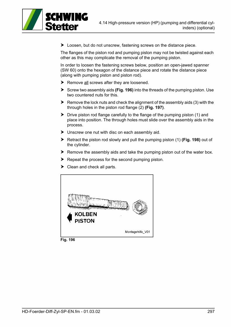
4.14 High-pressure version (HP) (pumping and differential cyl-inders) (optional)
Loosen, but do not unscrew, fastening screws on the distance piece.
The flanges of the piston rod and pumping piston may not be twisted against each other as this may complicate the removal of the pumping piston.
In order to loosen the fastening screws below, position an open-jawed spanner (SW 60) onto the hexagon of the distance piece and rotate the distance piece (along with pumping piston and piston rod).
Remove all screws after they are loosened.
Screw two assembly aids (Fig. 196) into the threads of the pumping piston. Use two countered nuts for this.
Remove the lock nuts and check the alignment of the assembly aids (3) with the through holes in the piston rod flange (2) (Fig. 197).
Drive piston rod flange carefully to the flange of the pumping piston (1) and place into position. The through holes must slide over the assembly aids in the process.
Unscrew one nut with disc on each assembly aid.
Retract the piston rod slowly and pull the pumping piston (1) (Fig. 198) out of the cylinder.
Remove the assembly aids and take the pumping piston out of the water box.
Repeat the process for the second pumping piston.
Clean and check all parts.
Fig. 196
HD-Foerder-Diff-Zyl-SP-EN.fm - 01.03.02 297
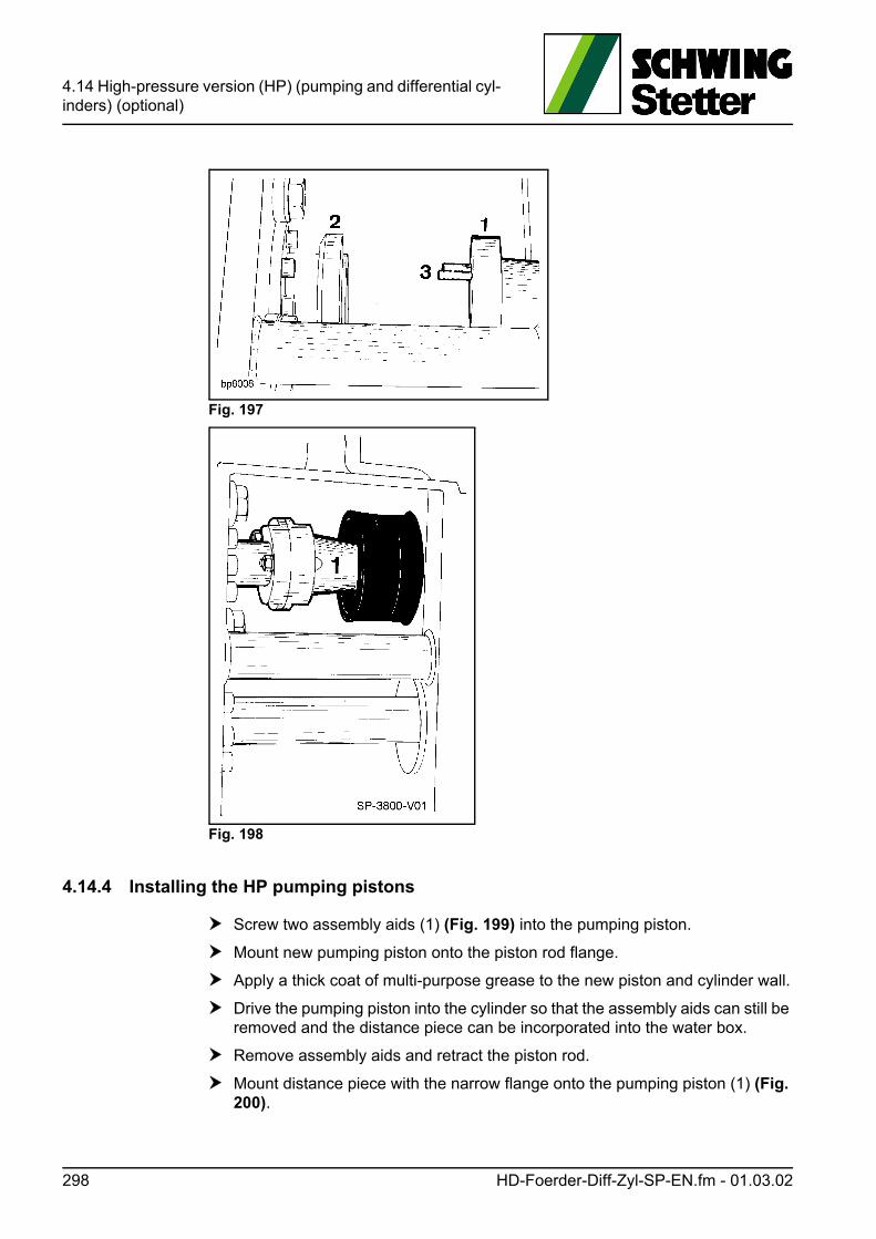
4.14 High-pressure version (HP) (pumping and differential cyl-inders) (optional)
Fig. 197
Fig. 198
4.14.4 Installing the HP pumping pistons
Screw two assembly aids (1) (Fig. 199) into the pumping piston.
Mount new pumping piston onto the piston rod flange.
Apply a thick coat of multi-purpose grease to the new piston and cylinder wall.
Drive the pumping piston into the cylinder so that the assembly aids can still be removed and the distance piece can be incorporated into the water box.
Remove assembly aids and retract the piston rod.
Mount distance piece with the narrow flange onto the pumping piston (1) (Fig. 200).
298 HD-Foerder-Diff-Zyl-SP-EN.fm - 01.03.02
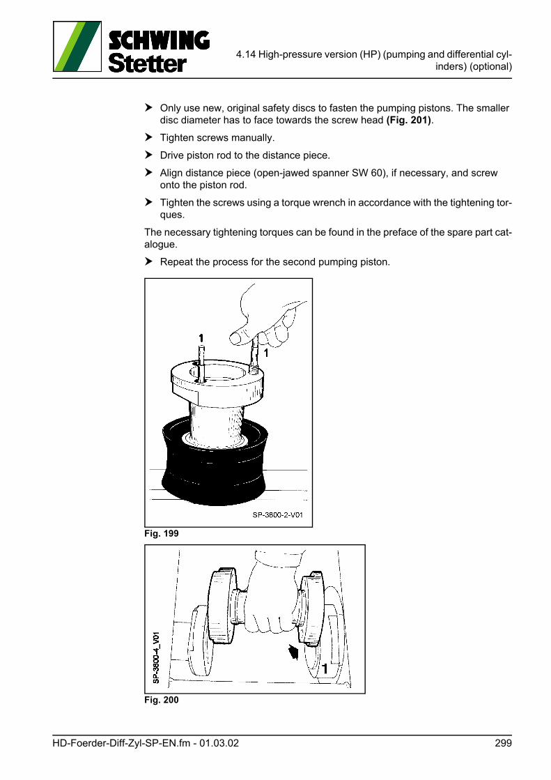
4.14 High-pressure version (HP) (pumping and differential cyl-inders) (optional)
Only use new, original safety discs to fasten the pumping pistons. The smaller disc diameter has to face towards the screw head (Fig. 201).
Tighten screws manually.
Drive piston rod to the distance piece.
Align distance piece (open-jawed spanner SW 60), if necessary, and screw onto the piston rod.
Tighten the screws using a torque wrench in accordance with the tightening tor-ques.
The necessary tightening torques can be found in the preface of the spare part cat-alogue.
Repeat the process for the second pumping piston.
Fig. 199
Fig. 200
HD-Foerder-Diff-Zyl-SP-EN.fm - 01.03.02 299
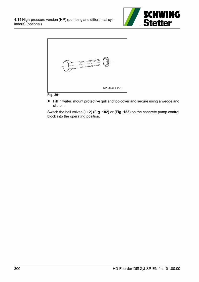
4.14 High-pressure version (HP) (pumping and differential cyl-inders) (optional)
Fig. 201
Fill in water, mount protective grill and top cover and secure using a wedge and clip pin.
Switch the ball valves (1+2) (Fig. 182) or (Fig. 183) on the concrete pump control block into the operating position.
300 HD-Foerder-Diff-Zyl-SP-EN.fm - 01.00.00
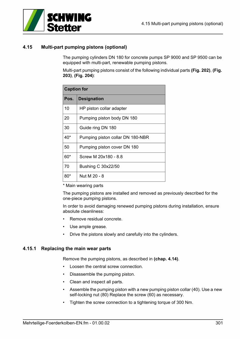
4.15 Multi-part pumping pistons (optional)
4.15 Multi-part pumping pistons (optional)
The pumping cylinders DN 180 for concrete pumps SP 9000 and SP 9500 can be equipped with multi-part, renewable pumping pistons.
Multi-part pumping pistons consist of the following individual parts (Fig. 202), (Fig. 203), (Fig. 204):
* Main wearing parts
The pumping pistons are installed and removed as previously described for the one-piece pumping pistons.
In order to avoid damaging renewed pumping pistons during installation, ensure absolute cleanliness:
• Remove residual concrete.
• Use ample grease.
• Drive the pistons slowly and carefully into the cylinders.
4.15.1 Replacing the main wear parts
Remove the pumping pistons, as described in (chap. 4.14).
• Loosen the central screw connection.
• Disassemble the pumping piston.
• Clean and inspect all parts.
• Assemble the pumping piston with a new pumping piston collar (40). Use a new self-locking nut (80) Replace the screw (60) as necessary.
• Tighten the screw connection to a tightening torque of 300 Nm.
Caption for
Pos. Designation
10 HP piston collar adapter
20 Pumping piston body DN 180
30 Guide ring DN 180
40* Pumping piston collar DN 180-NBR
50 Pumping piston cover DN 180
60* Screw M 20x180 - 8.8
70 Bushing C 30x22/50
80* Nut M 20 - 8
Mehrteilige-Foerderkolben-EN.fm - 01.00.02 301
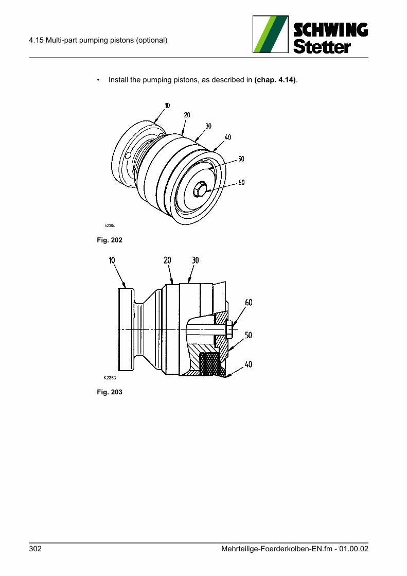
4.15 Multi-part pumping pistons (optional)
• Install the pumping pistons, as described in (chap. 4.14).
Fig. 202
Fig. 203
302 Mehrteilige-Foerderkolben-EN.fm - 01.00.02
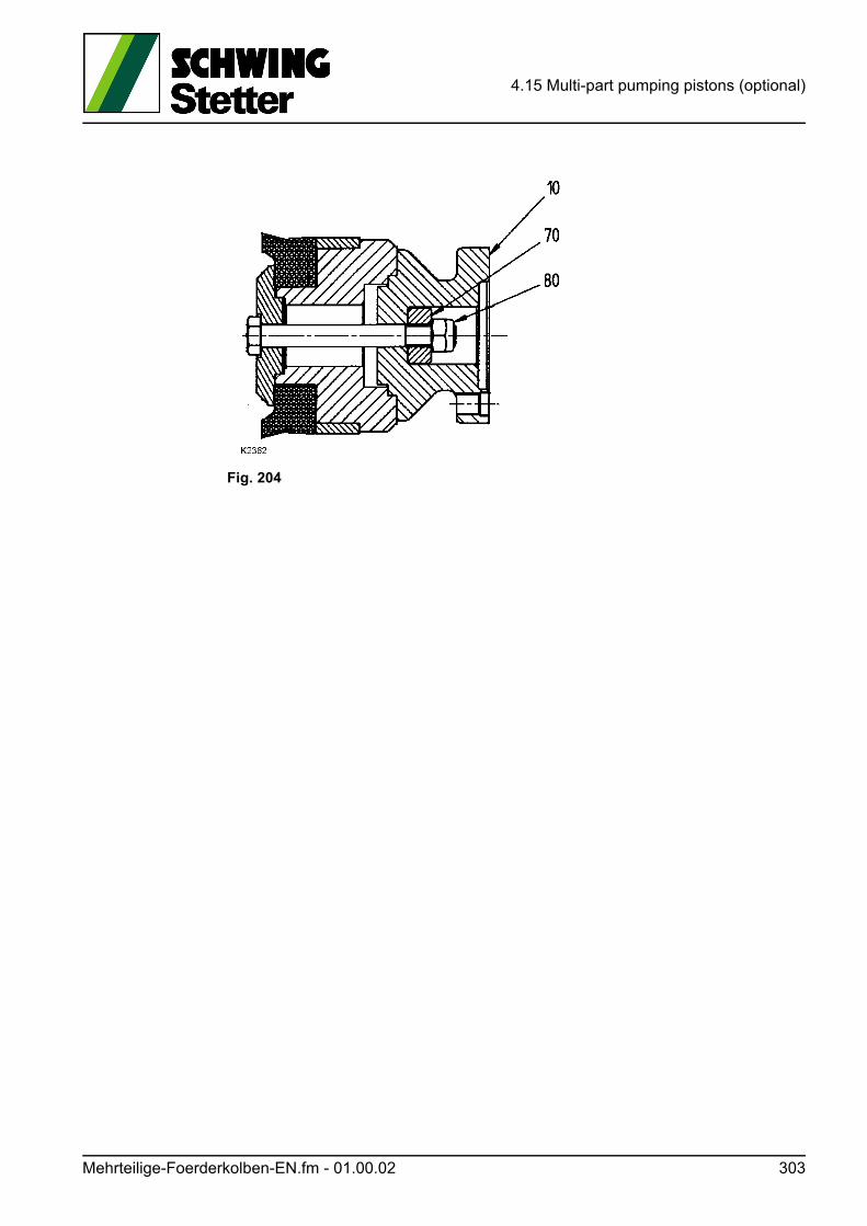
4.15 Multi-part pumping pistons (optional)
Fig. 204
Mehrteilige-Foerderkolben-EN.fm - 01.00.02 303

4.15 Multi-part pumping pistons (optional)
304 Mehrteilige-Foerderkolben-EN.fm - 01.00.02
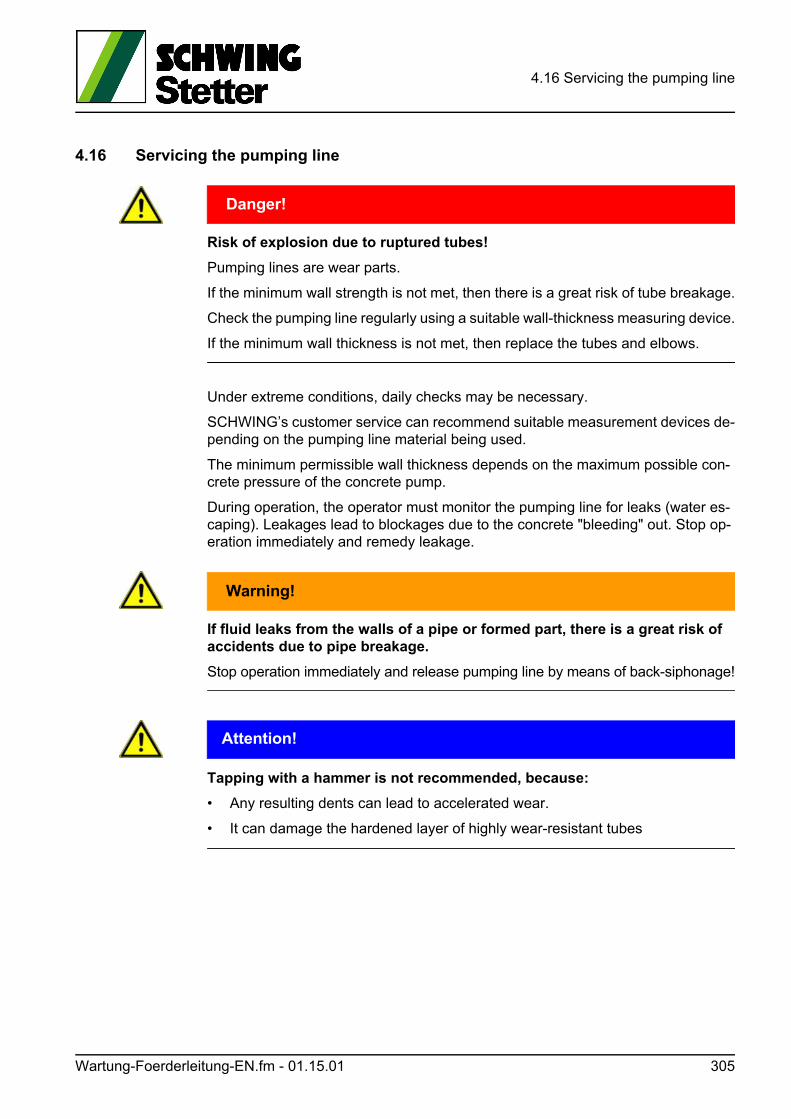
4.16 Servicing the pumping line
4.16 Servicing the pumping line
GEFAHR! Danger!
Risk of explosion due to ruptured tubes!
Pumping lines are wear parts.
If the minimum wall strength is not met, then there is a great risk of tube breakage.
Check the pumping line regularly using a suitable wall-thickness measuring device.
If the minimum wall thickness is not met, then replace the tubes and elbows.
Under extreme conditions, daily checks may be necessary.
SCHWING’s customer service can recommend suitable measurement devices de-pending on the pumping line material being used.
The minimum permissible wall thickness depends on the maximum possible con-crete pressure of the concrete pump.
During operation, the operator must monitor the pumping line for leaks (water es-caping). Leakages lead to blockages due to the concrete "bleeding" out. Stop op-eration immediately and remedy leakage.
WARNUNG! Warning!
If fluid leaks from the walls of a pipe or formed part, there is a great risk of accidents due to pipe breakage.
Stop operation immediately and release pumping line by means of back-siphonage!
ACHTUNG! Attention!
Tapping with a hammer is not recommended, because:
• Any resulting dents can lead to accelerated wear.
• It can damage the hardened layer of highly wear-resistant tubes
Wartung-Foerderleitung-EN.fm - 01.15.01 305
4.16 Servicing the pumping line
Information
Depending on the installation situation, the wear and tear on the pumping lines can vary greatly.
Check the elbows and reductions under highest strain especially carefully.
Experience has shown that the concrete pump outlet as well as the “impact elbows” on the last section of the boom (see “Impact bend” on page 310) wear more quickly than the rest of the pumping line.
VORSICHT! Caution!
Injury caused by the cocking lever springing open!
When mounting split couplings, injuries can be caused by the cocking lever spring-ing open unexpectedly.
Injuries such as bone fractures to concussions are possible.
Secure the cocking lever of the split coupling immediately after closing the cocking lever by using the "safety for split couplings".
306 Wartung-Foerderleitung-EN.fm - 01.15.01
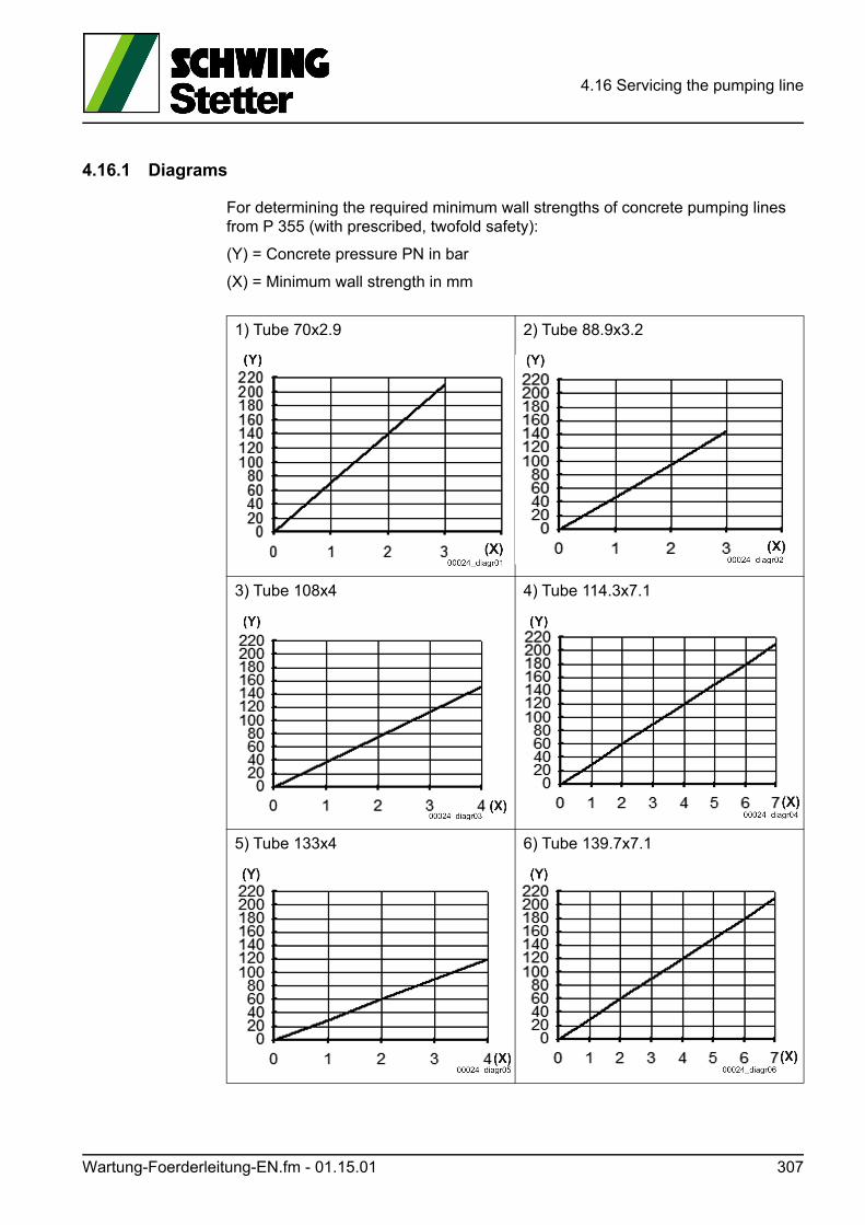
4.16 Servicing the pumping line
4.16.1 Diagrams
For determining the required minimum wall strengths of concrete pumping lines from P 355 (with prescribed, twofold safety):
(Y) = Concrete pressure PN in bar
(X) = Minimum wall strength in mm
1) Tube 70x2.9 2) Tube 88.9x3.2
3) Tube 108x4 4) Tube 114.3x7.1
5) Tube 133x4 6) Tube 139.7x7.1
Wartung-Foerderleitung-EN.fm - 01.15.01 307
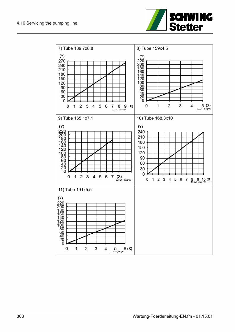
4.16 Servicing the pumping line
7) Tube 139.7x8.8 8) Tube 159x4.5
9) Tube 165.1x7.1 10) Tube 168.3x10
11) Tube 191x5.5
308 Wartung-Foerderleitung-EN.fm - 01.15.01
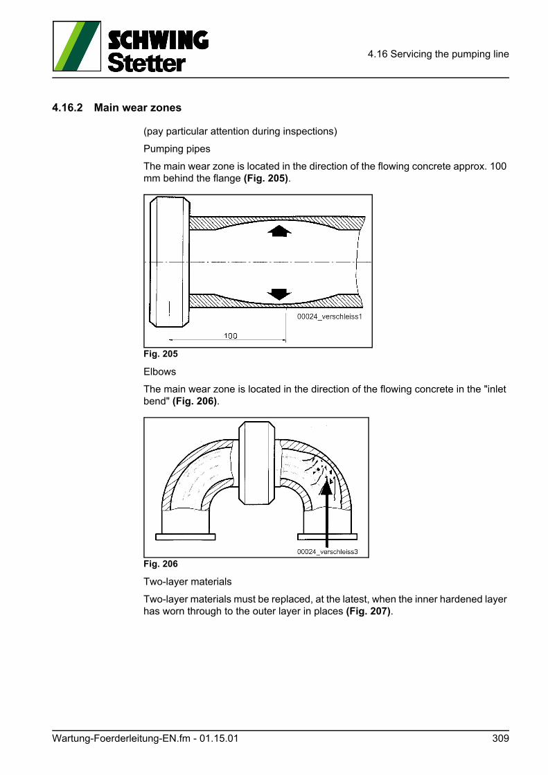
4.16 Servicing the pumping line
4.16.2 Main wear zones
(pay particular attention during inspections)
Pumping pipes
The main wear zone is located in the direction of the flowing concrete approx. 100 mm behind the flange (Fig. 205).
Fig. 205
Elbows
The main wear zone is located in the direction of the flowing concrete in the "inlet bend" (Fig. 206).
Fig. 206
Two-layer materials
Two-layer materials must be replaced, at the latest, when the inner hardened layer has worn through to the outer layer in places (Fig. 207).
Wartung-Foerderleitung-EN.fm - 01.15.01 309
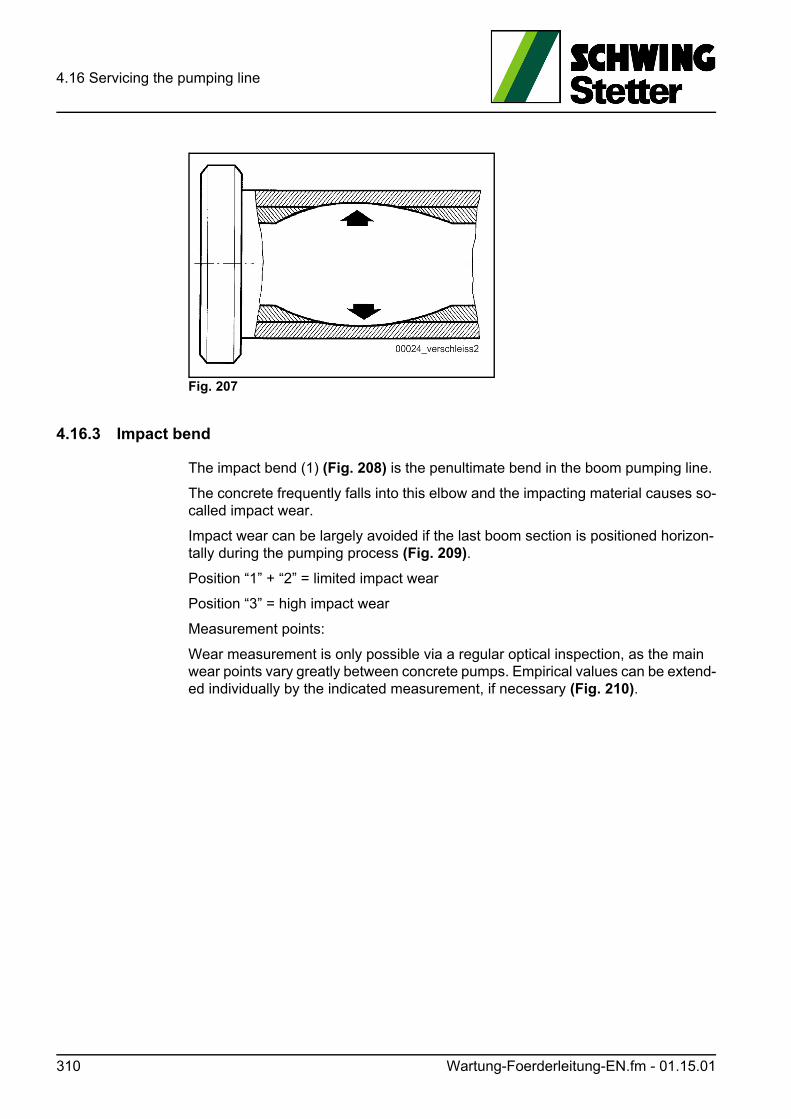
4.16 Servicing the pumping line
Fig. 207
4.16.3 Impact bend
The impact bend (1) (Fig. 208) is the penultimate bend in the boom pumping line.
The concrete frequently falls into this elbow and the impacting material causes so-called impact wear.
Impact wear can be largely avoided if the last boom section is positioned horizon-tally during the pumping process (Fig. 209).
Position “1” + “2” = limited impact wear
Position “3” = high impact wear
Measurement points:
Wear measurement is only possible via a regular optical inspection, as the main wear points vary greatly between concrete pumps. Empirical values can be extend-ed individually by the indicated measurement, if necessary (Fig. 210).
310 Wartung-Foerderleitung-EN.fm - 01.15.01
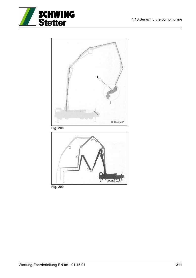
4.16 Servicing the pumping line
Fig. 208
Fig. 209
Wartung-Foerderleitung-EN.fm - 01.15.01 311
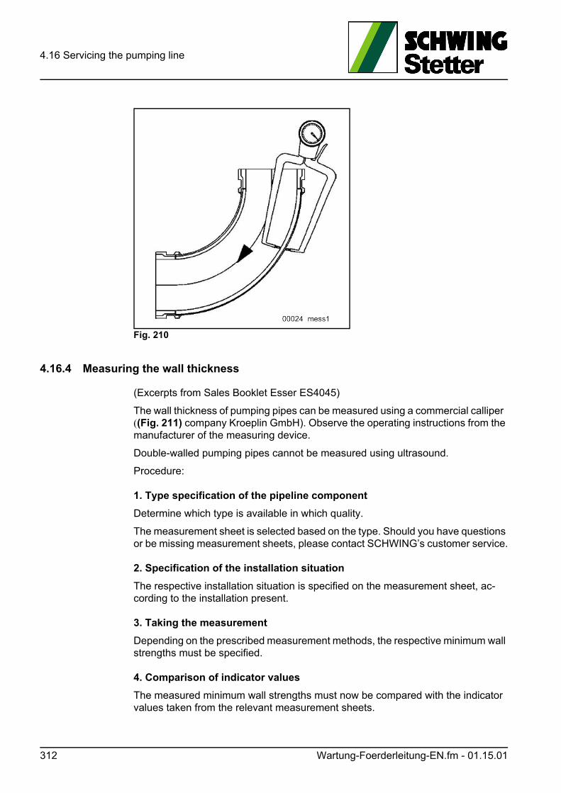
4.16 Servicing the pumping line
Fig. 210
4.16.4 Measuring the wall thickness
(Excerpts from Sales Booklet Esser ES4045)
The wall thickness of pumping pipes can be measured using a commercial calliper ((Fig. 211) company Kroeplin GmbH). Observe the operating instructions from the manufacturer of the measuring device.
Double-walled pumping pipes cannot be measured using ultrasound.
Procedure:
1. Type specification of the pipeline component
Determine which type is available in which quality.
The measurement sheet is selected based on the type. Should you have questions or be missing measurement sheets, please contact SCHWING’s customer service.
2. Specification of the installation situation
The respective installation situation is specified on the measurement sheet, ac-cording to the installation present.
3. Taking the measurement
Depending on the prescribed measurement methods, the respective minimum wall strengths must be specified.
4. Comparison of indicator values
The measured minimum wall strengths must now be compared with the indicator values taken from the relevant measurement sheets.
312 Wartung-Foerderleitung-EN.fm - 01.15.01
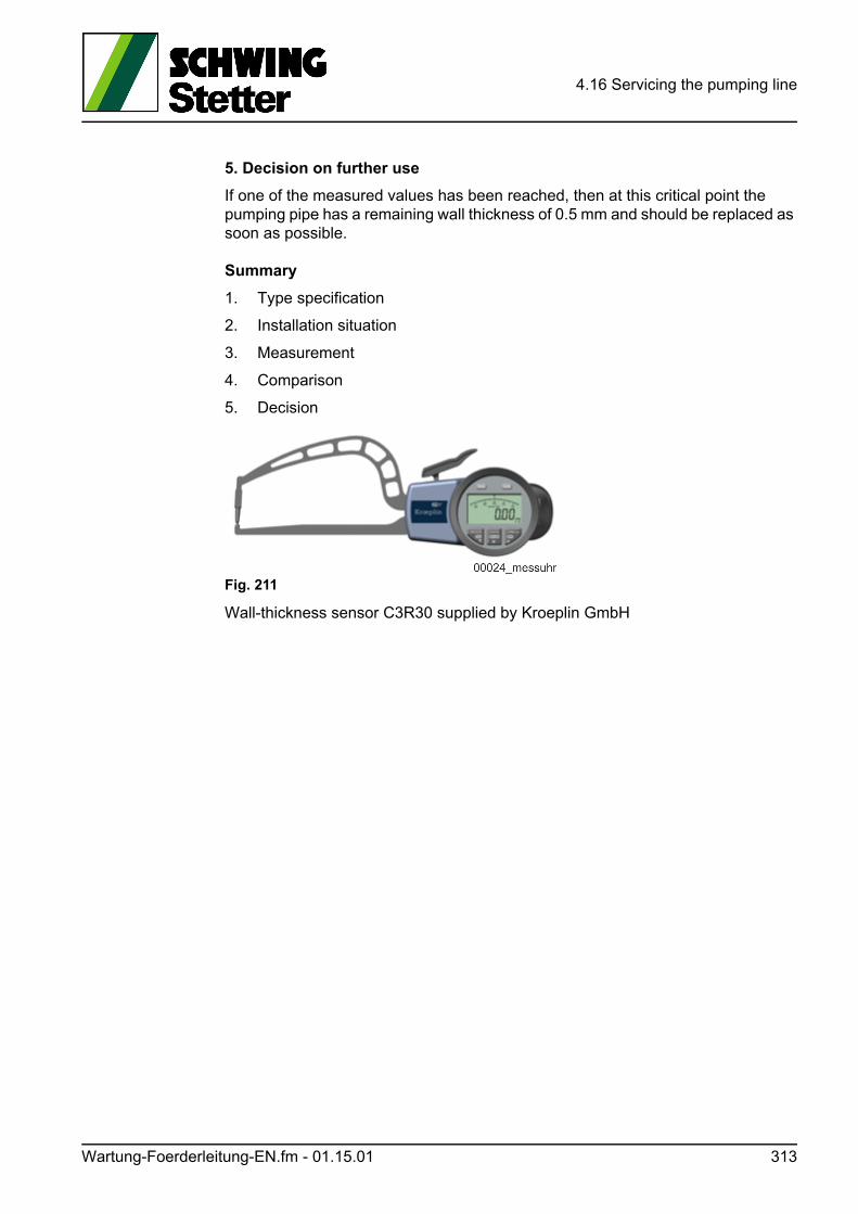
4.16 Servicing the pumping line
5. Decision on further use
If one of the measured values has been reached, then at this critical point the pumping pipe has a remaining wall thickness of 0.5 mm and should be replaced as soon as possible.
Summary
1. Type specification
2. Installation situation
3. Measurement
4. Comparison
5. Decision
Fig. 211
Wall-thickness sensor C3R30 supplied by Kroeplin GmbH
Wartung-Foerderleitung-EN.fm - 01.15.01 313
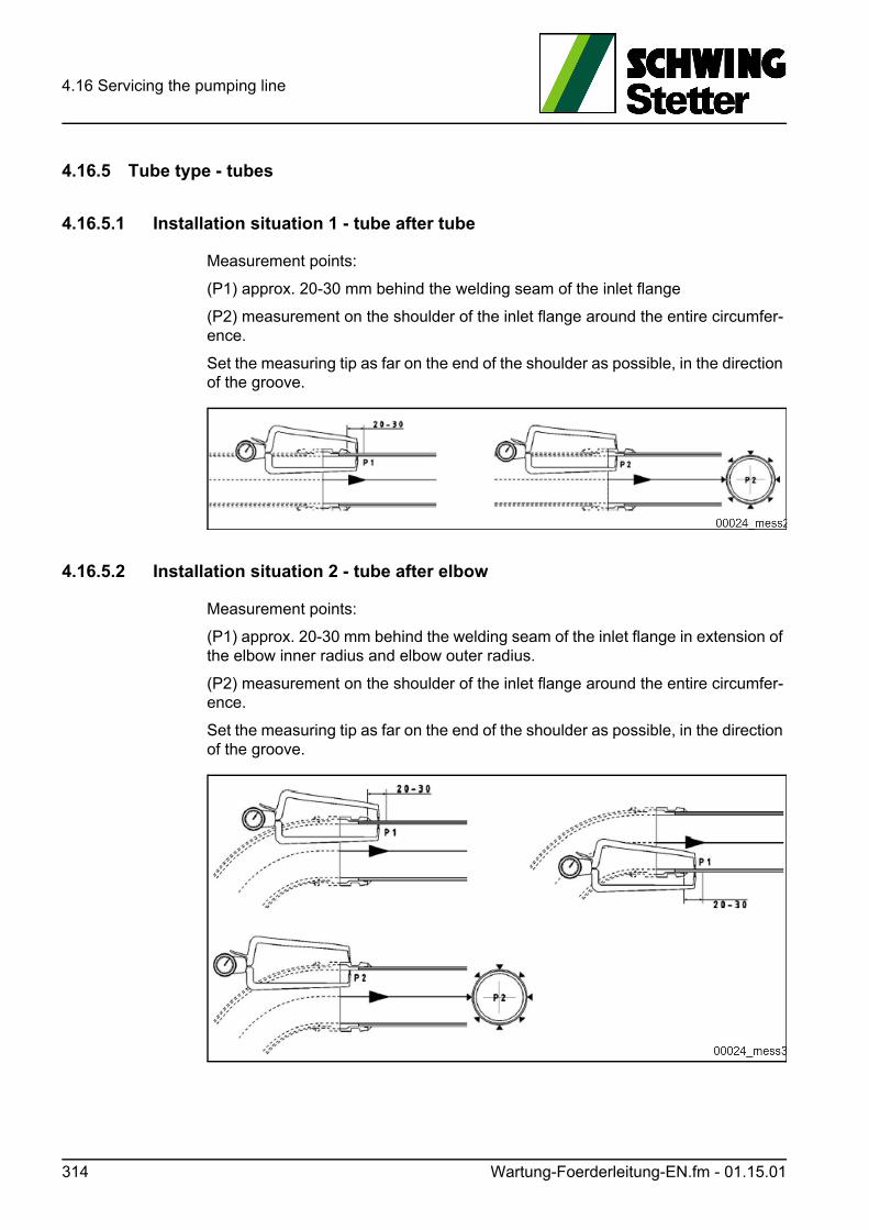
4.16 Servicing the pumping line
4.16.5 Tube type - tubes
4.16.5.1 Installation situation 1 - tube after tube
Measurement points:
(P1) approx. 20-30 mm behind the welding seam of the inlet flange
(P2) measurement on the shoulder of the inlet flange around the entire circumfer-ence.
Set the measuring tip as far on the end of the shoulder as possible, in the direction of the groove.
4.16.5.2 Installation situation 2 - tube after elbow
Measurement points:
(P1) approx. 20-30 mm behind the welding seam of the inlet flange in extension of the elbow inner radius and elbow outer radius.
(P2) measurement on the shoulder of the inlet flange around the entire circumfer-ence.
Set the measuring tip as far on the end of the shoulder as possible, in the direction of the groove.
314 Wartung-Foerderleitung-EN.fm - 01.15.01
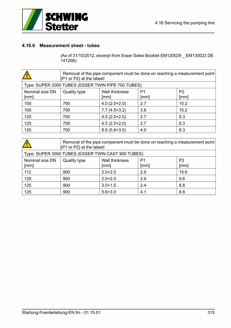
4.16 Servicing the pumping line
4.16.6 Measurement sheet - tubes
(As of 31/10/2012, excerpt from Esser Sales Booklet EM120029 _ EM130023 DE 141208):
Removal of the pipe component must be done on reaching a measurement point (P1 or P2) at the latest!
Type: SUPER 2000 TUBES (ESSER TWIN PIPE 700 TUBES)
Nominal size DN[mm]
Quality type Wall thickness[mm]
P1[mm]
P2[mm]
100 700 4.0 (2.0+2.0) 2.7 10.2
100 700 7.7 (4.5+3.2) 3.8 10.2
125 700 4.0 (2.0+2.0) 2.7 8.3
125 700 4.5 (2.5+2.0) 2.7 8.3
125 700 8.6 (5.6+3.0) 4.0 8.3
Removal of the pipe component must be done on reaching a measurement point (P1 or P2) at the latest!
Type: SUPER 3000 TUBES (ESSER TWIN CAST 900 TUBES)
Nominal size DN[mm]
Quality type Wall thickness[mm]
P1[mm]
P2[mm]
112 900 2.0+2.0 2.9 15.6
125 900 2.0+2.0 2.9 9.6
125 900 3.0+1.5 2.4 8.8
125 900 5.6+3.0 4.1 8.8
Wartung-Foerderleitung-EN.fm - 01.15.01 315
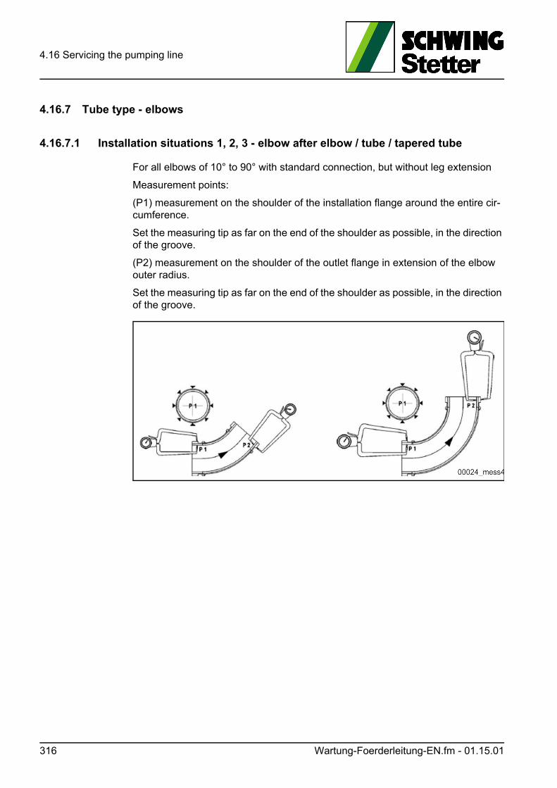
4.16 Servicing the pumping line
4.16.7 Tube type - elbows
4.16.7.1 Installation situations 1, 2, 3 - elbow after elbow / tube / tapered tube
For all elbows of 10° to 90° with standard connection, but without leg extension
Measurement points:
(P1) measurement on the shoulder of the installation flange around the entire cir-cumference.
Set the measuring tip as far on the end of the shoulder as possible, in the direction of the groove.
(P2) measurement on the shoulder of the outlet flange in extension of the elbow outer radius.
Set the measuring tip as far on the end of the shoulder as possible, in the direction of the groove.
316 Wartung-Foerderleitung-EN.fm - 01.15.01
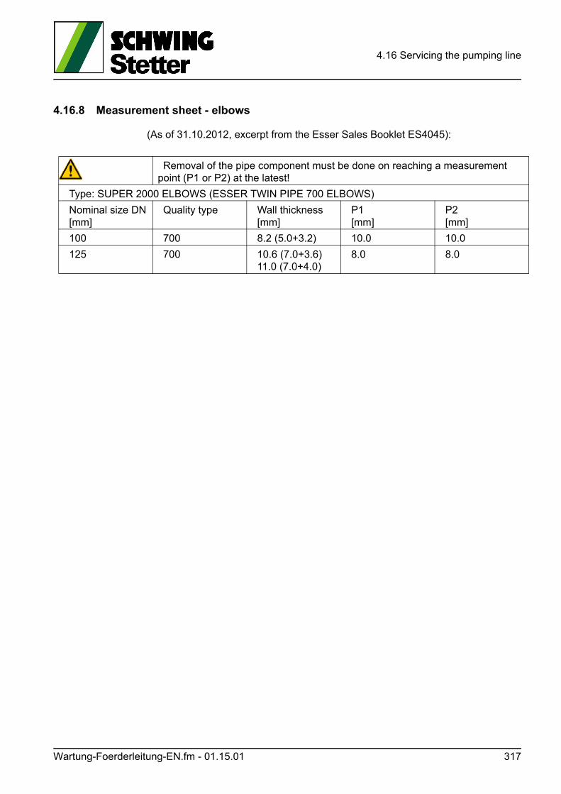
4.16 Servicing the pumping line
4.16.8 Measurement sheet - elbows
(As of 31.10.2012, excerpt from the Esser Sales Booklet ES4045):
Removal of the pipe component must be done on reaching a measurement point (P1 or P2) at the latest!
Type: SUPER 2000 ELBOWS (ESSER TWIN PIPE 700 ELBOWS)
Nominal size DN[mm]
Quality type Wall thickness[mm]
P1[mm]
P2[mm]
100 700 8.2 (5.0+3.2) 10.0 10.0
125 700 10.6 (7.0+3.6)11.0 (7.0+4.0)
8.0 8.0
Wartung-Foerderleitung-EN.fm - 01.15.01 317
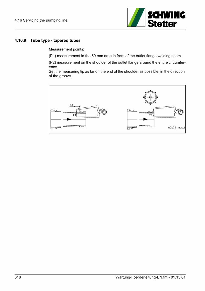
4.16 Servicing the pumping line
4.16.9 Tube type - tapered tubes
Measurement points:
(P1) measurement in the 50 mm area in front of the outlet flange welding seam.
(P2) measurement on the shoulder of the outlet flange around the entire circumfer-ence.Set the measuring tip as far on the end of the shoulder as possible, in the direction of the groove.
318 Wartung-Foerderleitung-EN.fm - 01.15.01
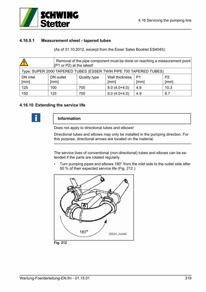
4.16 Servicing the pumping line
4.16.9.1 Measurement sheet - tapered tubes
(As of 31.10.2012, excerpt from the Esser Sales Booklet ES4045):
4.16.10 Extending the service life
Information
Does not apply to directional tubes and elbows!
Directional tubes and elbows may only be installed in the pumping direction. For this purpose, directional arrows are located on the material.
The service lives of conventional (non-directional) tubes and elbows can be ex-tended if the parts are rotated regularly.
• Turn pumping pipes and elbows 180° from the inlet side to the outlet side after 50 % of their expected service life (Fig. 212 ).
Fig. 212
Removal of the pipe component must be done on reaching a measurement point (P1 or P2) at the latest!
Type: SUPER 2000 TAPERED TUBES (ESSER TWIN PIPE 700 TAPERED TUBES)
DN inlet[mm]
DN outlet[mm]
Quality type Wall thickness[mm]
P1[mm]
P2[mm]
125 100 700 8.0 (4.0+4.0) 4.9 10.3
150 125 700 8.0 (4.0+4.0) 4.9 8.7
Wartung-Foerderleitung-EN.fm - 01.15.01 319
4.16 Servicing the pumping line
4.16.11 Replacing pumping pipes end elbows
Information
Directional tubes and elbows may only be installed in the pumping direction.
For this purpose, directional arrows are located on the material.
• Pay attention to the quality and correct size of spare parts.
Only original SCHWING spare parts correspond exactly to the factory-installed parts.
• During the initial assembly at the factory, the boom pumping line is assembled without tension on a folded placing boom.
Incorrect assembly can lead to an increased load on the placing boom kinematics and damage such as broken line holders.
In order to avoid damage, likewise always exchange individual parts on a folded placing boom.
The length of the pipe installed in the pumping line outlet is specified on a sign on the machine (Fig. 213).
When pumping line parts are replaced later on, a different pipe length may be re-quired in some cases. For this reason, always give the required length when order-ing.
WARNUNG! Warning!
Pumping pipes and elbows can be very heavy!
A 3 m long pumping pipe DN 125 of Super 2000 quality weighs, for example, ap-prox. 45 kg.
Attach tubes and elbows to lifting gear before removing them.
• Use new seals and fuses for the couplings.
• Clean and check the couplings carefully.
• Lubricate the couplings and seals with a rubber-compatible lubricant, e.g. "Op-timol Olit CLS".
“Optimol Olit CLS” is a water-resistant, high-performance grease with a lithium/cal-cium base.
320 Wartung-Foerderleitung-EN.fm - 01.15.01
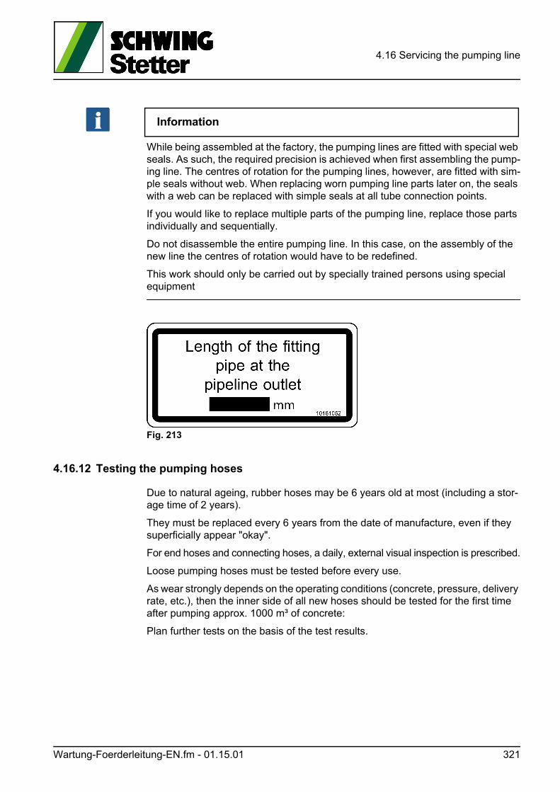
4.16 Servicing the pumping line
Information
While being assembled at the factory, the pumping lines are fitted with special web seals. As such, the required precision is achieved when first assembling the pump-ing line. The centres of rotation for the pumping lines, however, are fitted with sim-ple seals without web. When replacing worn pumping line parts later on, the seals with a web can be replaced with simple seals at all tube connection points.
If you would like to replace multiple parts of the pumping line, replace those parts individually and sequentially.
Do not disassemble the entire pumping line. In this case, on the assembly of the new line the centres of rotation would have to be redefined.
This work should only be carried out by specially trained persons using special equipment
Fig. 213
4.16.12 Testing the pumping hoses
Due to natural ageing, rubber hoses may be 6 years old at most (including a stor-age time of 2 years).
They must be replaced every 6 years from the date of manufacture, even if they superficially appear "okay".
For end hoses and connecting hoses, a daily, external visual inspection is prescribed.
Loose pumping hoses must be tested before every use.
As wear strongly depends on the operating conditions (concrete, pressure, delivery rate, etc.), then the inner side of all new hoses should be tested for the first time after pumping approx. 1000 m³ of concrete:
Plan further tests on the basis of the test results.
Wartung-Foerderleitung-EN.fm - 01.15.01 321
4.16 Servicing the pumping line
4.16.13 Visual inspection (exterior)
• Check the safety catch on one of the placing boom end hoses to make sure it is in proper working order.
• The outlet end of an end hose must not be "frayed".
• Check all pumping hoses for dents, kinks or other deformations that might indi-cate displaced or destroyed armour hose casing (steel cord insert).
• Check the outer skin for cuts, ruptures or abrasions that could imply damage to the armour hose casing.
Hoses with a damaged casing must be replaced!
4.16.14 Visual inspection (internal)
• Lay the cleaned hose out horizontally and use a pocket torch.
• Pay attention to points at which the armour casing is exposed or protrudes.
• Also pay attention to areas with loose rubber coating, dents, cuts and local wear zones.
• Check the main wear zones on the inlet side of the hose in particular. The heav-iest wear is located on the first 30 cm of the rubber coating (behind the fixing).
Hoses with damaged armour casing or excessive wear must be replaced!
4.16.15 Visual inspection of fixings
• Make sure the fixings are tight.
The hose and fixing must be firmly connected together.
• Check the inner sides of the fixings for wear.
• Check the sealing surfaces for damage and clean any concrete residue off of them.
Hoses with damaged or loose fixings (hose creeps out of the fixing) must be re-placed!
Information
Take extra care to check end hoses equipped with a non-return valve.
Due to the greater load, check end hoses with a non-return valve (Fig. 214) espe-cially carefully in the pressure area of the non-return valve.
322 Wartung-Foerderleitung-EN.fm - 01.15.01
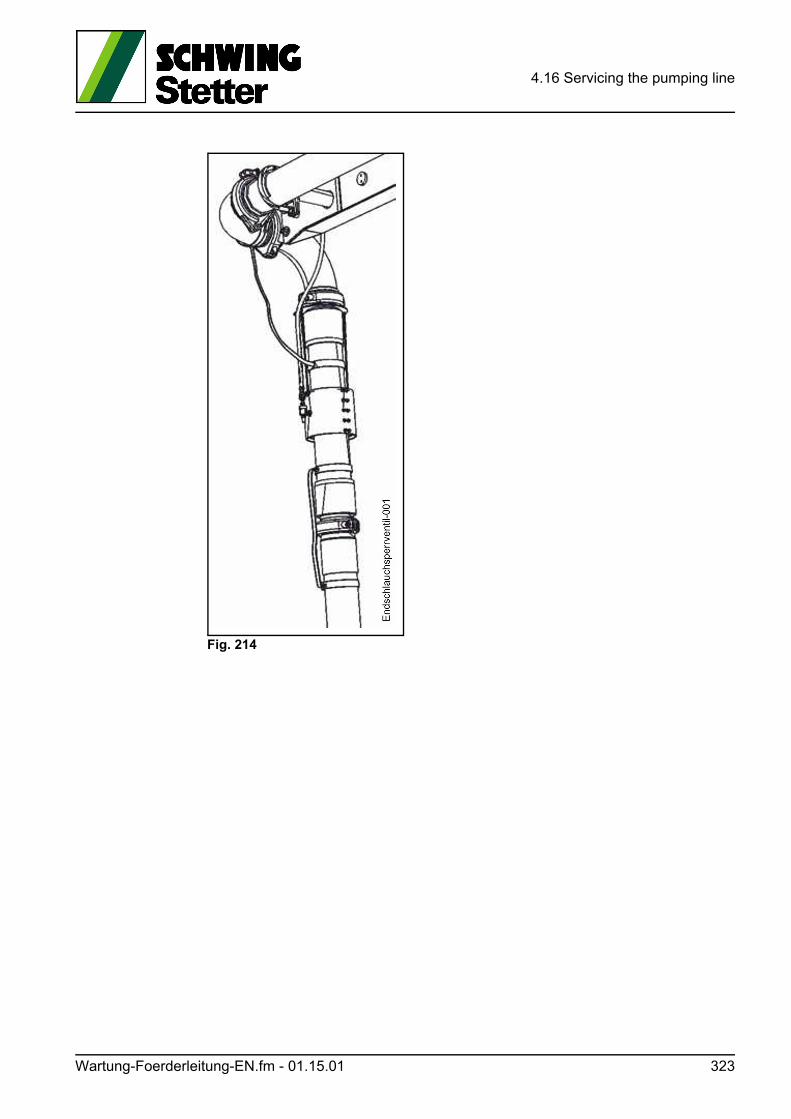
4.16 Servicing the pumping line
Fig. 214
Wartung-Foerderleitung-EN.fm - 01.15.01 323

4.16 Servicing the pumping line
324 Wartung-Foerderleitung-EN.fm - 01.15.01
4.17 Rotary compressor
4.17 Rotary compressor
4.17.1 Maintenance packages
SCHWING provides two different packages with material for servicing your com-pressor:
4.17.1.1 Maintenance package 1
(Standard maintenance) art. no.: 10197336
This package contains all filters, seals and a reservoir with compressor oil for the maintenance work described below.
The oil quantity is sufficient for an oil change and possible refill between changes.
4.17.1.2 Maintenance package 2
(Oil separator cartridge) art. no.: 10170388
This package contains an oil separator cartridge and all of the seals necessary for replacing it.
Information
In order to ensure safe and smooth operation, please only use the material men-tioned above.
SCHWING is not liable for any damages caused by improperly performed mainte-nance and/or unsuitable material.
* = Special equipment
Information
Read these instructions before starting with the work.
Do not use flammable substances and naked flames during cleaning work and maintenance.
Rotationskompressor-EN.fm - 01.02.01 325
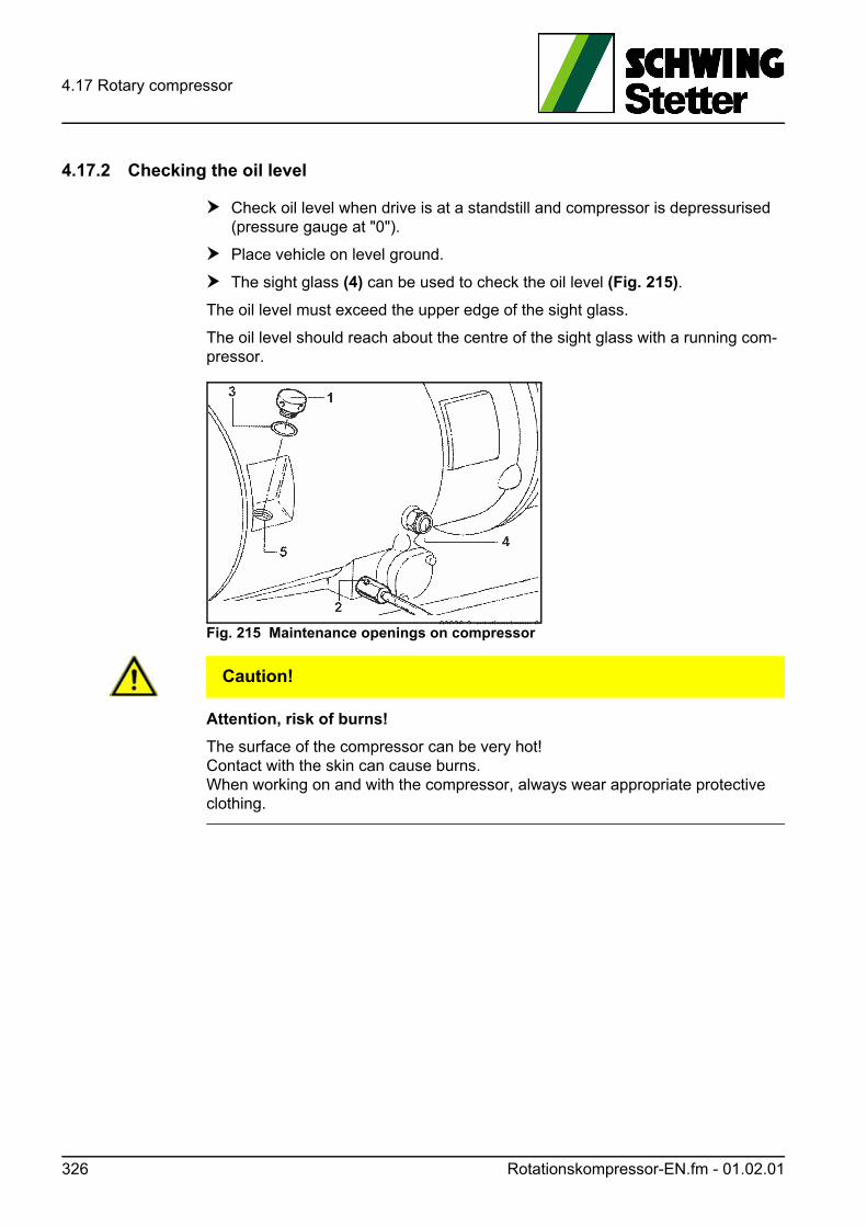
4.17 Rotary compressor
4.17.2 Checking the oil level
Check oil level when drive is at a standstill and compressor is depressurised (pressure gauge at "0").
Place vehicle on level ground.
The sight glass (4) can be used to check the oil level (Fig. 215).
The oil level must exceed the upper edge of the sight glass.
The oil level should reach about the centre of the sight glass with a running com-pressor.
Fig. 215 Maintenance openings on compressor
VORSICHT! Caution!
Attention, risk of burns!
The surface of the compressor can be very hot!Contact with the skin can cause burns.When working on and with the compressor, always wear appropriate protective clothing.
326 Rotationskompressor-EN.fm - 01.02.01
4.17 Rotary compressor
4.17.3 Topping up the oil
Top up oil when drive is at a standstill and compressor is depressurised (pres-sure gauge at "0").
Carefully open the filler plug (1) (Fig. 215) to equalise the pressure.
Make sure that no oil foam emerges from the opening (5).
Wait a few minutes, if necessary, until the oil foam has reduced.
Only use the same oil for refill as is in the compressor.
ACHTUNG! Attention!
Material damage caused by the wrong compressor oil.
Using the wrong oils or mixtures of various oil types can cause severe material damage to the compressor.
Always use the recommended oil and do not mix compressor oils of different brands and viscosities.
Refill the oil until it overflows over the opening (5).
Replace the sealing ring (3) and attach the filler plug (1).
4.17.4 Changing the oil
Drain the oil at operating temperature for it to drain properly.
First loosen the filler plug (1) as described above.
Open the drain cock (2).
Close the drain cock after emptying it completely.
Fill in new oil, as described above.
Let the compressor run for a few minutes, then check the oil level and check for leaks. Add more oil, if necessary.
Rotationskompressor-EN.fm - 01.02.01 327
4.17 Rotary compressor
Information
New compressors are filled with a run-in oil. That oil must be changed during the first oil change with a compressor oil recommended by the compressor manufac-turer.
Using the correct oil is imperative for the safe function of the compressor.
Only use the Rotor Oil 8000 F2 included in maintenance package 1.
Rotor Oil 8000 F 2 is a synthetic all-season oil suitable for an ambient temperature of -25 to 40 °C.
It may not, under any circumstances, be mixed with other oils.
4.17.5 Cleaning / Replacing the air filter
Loosen the knurled nuts (1) (Fig. 216).
Remove the sealing ring (2) and filter cover (3).
Pull out the filter insert (4).
Clean all parts with compressed air (max. 5 bar).
Blow out the filter insert from the inside out using upward and downward move-ments until dust no longer emerges.
After multiple cleanings, replace the filter insert in accordance with the mainte-nance schedule (see “Maintenance plan for stationary concrete pump” on page 245).
Install filter in reverse order.
4.17.6 Cleaning the oil cooler
Clean the cooling fins of the oil cooler with a compressed air gun (Fig. 217).
A dirty cooler causes the oil to heat up more and can result in outages due to over-heating. If oil is too hot, it ages faster and loses its lubrication properties. This in-creases the wear on the compressor.
Blow the compressed air opposite the normal flow direction of the cooling air.
328 Rotationskompressor-EN.fm - 01.02.01
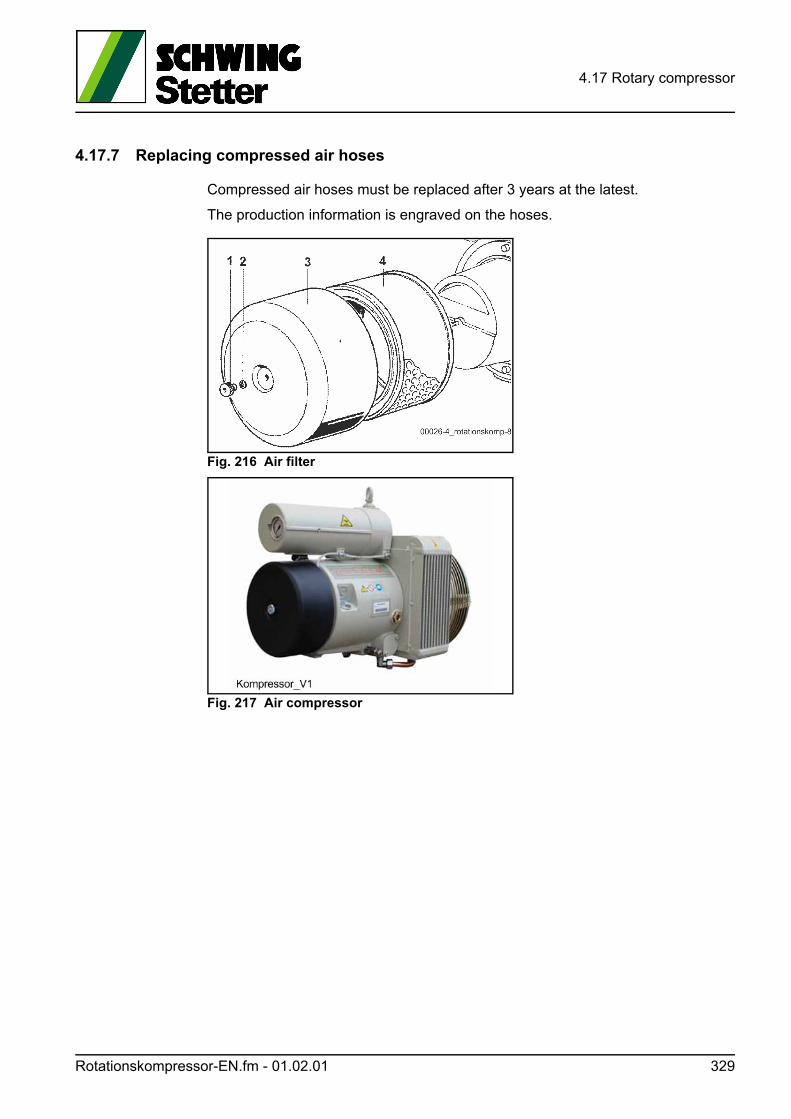
4.17 Rotary compressor
4.17.7 Replacing compressed air hoses
Compressed air hoses must be replaced after 3 years at the latest.
The production information is engraved on the hoses.
Fig. 216 Air filter
Fig. 217 Air compressor
Rotationskompressor-EN.fm - 01.02.01 329
4.17 Rotary compressor
4.17.8 Replacing the oil filter
Drain the old oil as described above.
Loosen the screws (1) on the filter cover (2) (Fig. 219).
Rotate the top cover 90° and remove the cover together with the filter.
Remove the filter (3) from the top cover.
Clean the top cover and seating surfaces of the housing.
WARNUNG! Warning!
Do not use flammable cleaning agents!
No traces of cleaning agent may get into the compressor.
Attach a new filter to the top cover.
Attach the top cover with a new sealing ring (4).
Top up the compressor oil as described above.
4.17.9 Replacing oil return valves
Loosen the hollow screws (1) (Fig. 218).
Pay attention to the sealing rings (3).
Unscrew the return valves (4) from the separator housing.
Install new valves with new O-rings (5).
Attach the screw connections (2) with new sealing rings (3).
330 Rotationskompressor-EN.fm - 01.02.01
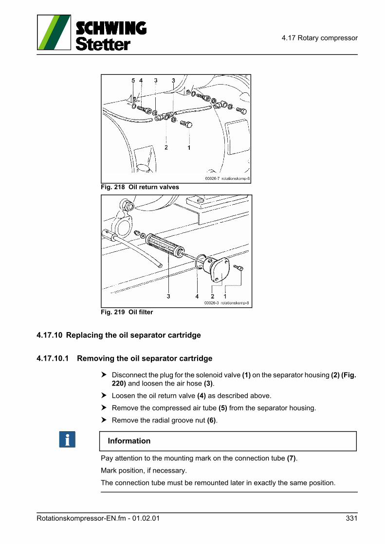
4.17 Rotary compressor
Fig. 218 Oil return valves
Fig. 219 Oil filter
4.17.10 Replacing the oil separator cartridge
4.17.10.1 Removing the oil separator cartridge
Disconnect the plug for the solenoid valve (1) on the separator housing (2) (Fig. 220) and loosen the air hose (3).
Loosen the oil return valve (4) as described above.
Remove the compressed air tube (5) from the separator housing.
Remove the radial groove nut (6).
Information
Pay attention to the mounting mark on the connection tube (7).
Mark position, if necessary.
The connection tube must be remounted later in exactly the same position.
Rotationskompressor-EN.fm - 01.02.01 331
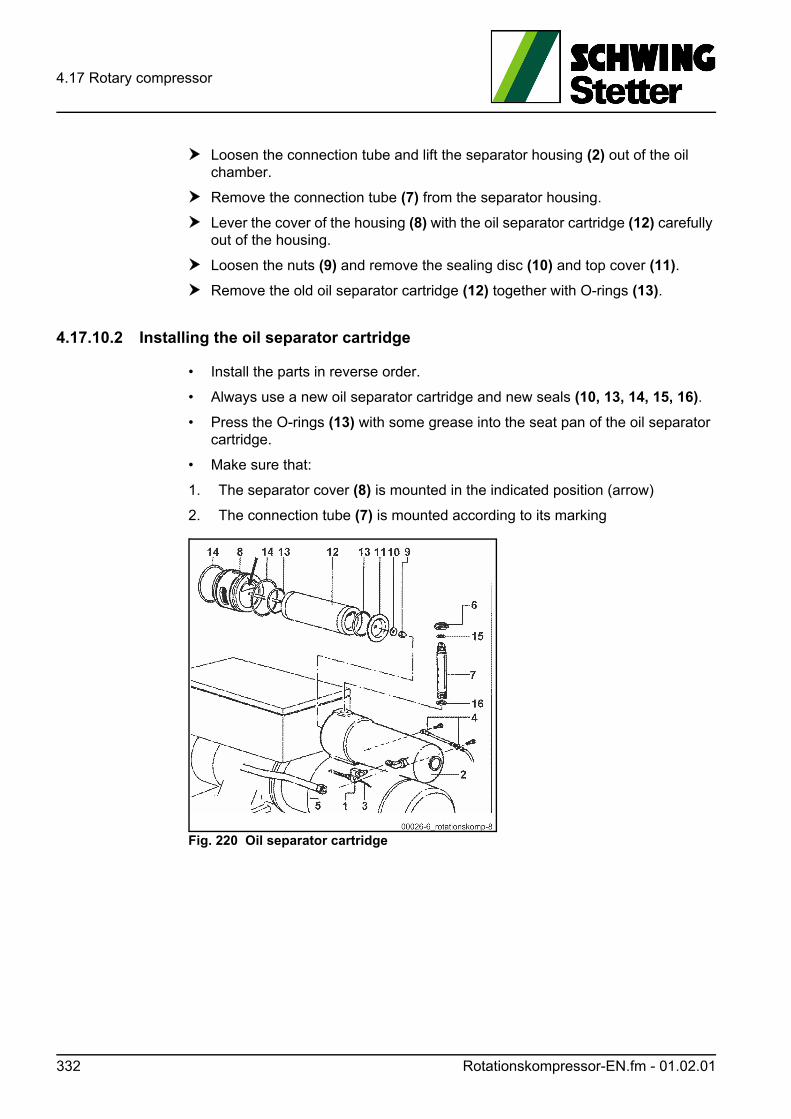
4.17 Rotary compressor
Loosen the connection tube and lift the separator housing (2) out of the oil chamber.
Remove the connection tube (7) from the separator housing.
Lever the cover of the housing (8) with the oil separator cartridge (12) carefully out of the housing.
Loosen the nuts (9) and remove the sealing disc (10) and top cover (11).
Remove the old oil separator cartridge (12) together with O-rings (13).
4.17.10.2 Installing the oil separator cartridge
• Install the parts in reverse order.
• Always use a new oil separator cartridge and new seals (10, 13, 14, 15, 16).
• Press the O-rings (13) with some grease into the seat pan of the oil separator cartridge.
• Make sure that:
1. The separator cover (8) is mounted in the indicated position (arrow)
2. The connection tube (7) is mounted according to its marking
Fig. 220 Oil separator cartridge
332 Rotationskompressor-EN.fm - 01.02.01
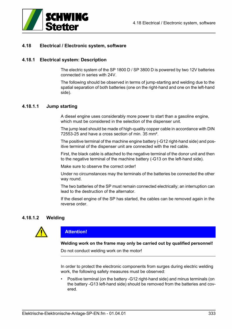
4.18 Electrical / Electronic system, software
4.18 Electrical / Electronic system, software
4.18.1 Electrical system: Description
The electric system of the SP 1800 D / SP 3800 D is powered by two 12V batteries connected in series with 24V.
The following should be observed in terms of jump-starting and welding due to the spatial separation of both batteries (one on the right-hand and one on the left-hand side).
4.18.1.1 Jump starting
A diesel engine uses considerably more power to start than a gasoline engine, which must be considered in the selection of the dispenser unit.
The jump lead should be made of high-quality copper cable in accordance with DIN 72553-25 and have a cross section of min. 35 mm².
The positive terminal of the machine engine battery (-G12 right-hand side) and pos-itive terminal of the dispenser unit are connected with the red cable.
First, the black cable is attached to the negative terminal of the donor unit and then to the negative terminal of the machine battery (-G13 on the left-hand side).
Make sure to observe the correct order!
Under no circumstances may the terminals of the batteries be connected the other way round.
The two batteries of the SP must remain connected electrically; an interruption can lead to the destruction of the alternator.
If the diesel engine of the SP has started, the cables can be removed again in the reverse order.
4.18.1.2 Welding
ACHTUNG! Attention!
Welding work on the frame may only be carried out by qualified personnel!
Do not conduct welding work on the motor!
In order to protect the electronic components from surges during electric welding work, the following safety measures must be observed:
• Positive terminal (on the battery -G12 right-hand side) and minus terminals (on the battery -G13 left-hand side) should be removed from the batteries and cov-ered.
Elektrische-Elektronische-Anlage-SP-EN.fm - 01.04.01 333
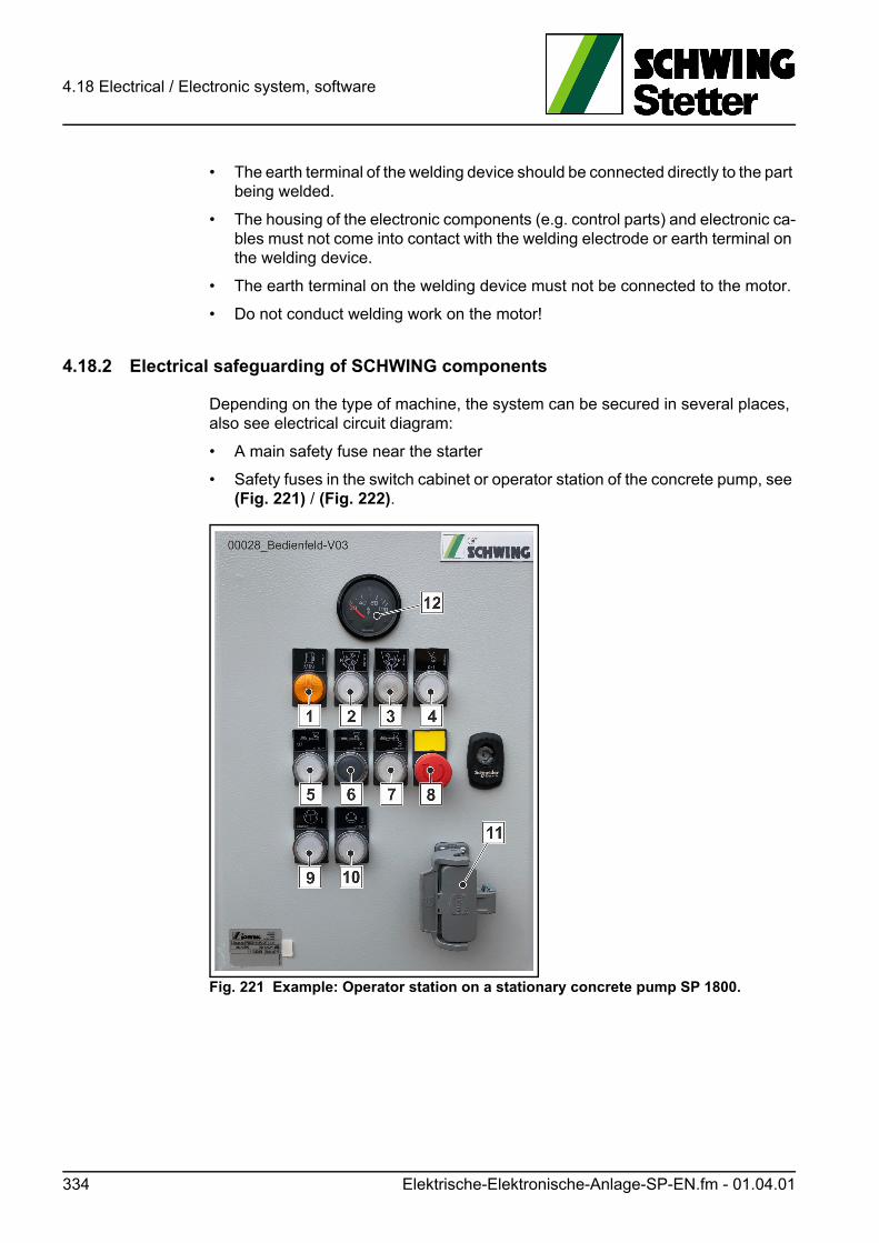
4.18 Electrical / Electronic system, software
• The earth terminal of the welding device should be connected directly to the part being welded.
• The housing of the electronic components (e.g. control parts) and electronic ca-bles must not come into contact with the welding electrode or earth terminal on the welding device.
• The earth terminal on the welding device must not be connected to the motor.
• Do not conduct welding work on the motor!
4.18.2 Electrical safeguarding of SCHWING components
Depending on the type of machine, the system can be secured in several places, also see electrical circuit diagram:
• A main safety fuse near the starter
• Safety fuses in the switch cabinet or operator station of the concrete pump, see (Fig. 221) / (Fig. 222).
Fig. 221 Example: Operator station on a stationary concrete pump SP 1800.
334 Elektrische-Elektronische-Anlage-SP-EN.fm - 01.04.01

4.18 Electrical / Electronic system, software
.
Fig. 222 Example: Operator station on a stationary concrete pump SP 3800.
4.18.3 Changing the fuses in SCHWING components
Switch off the machine’s control unit and the drive motor.
Switch the main battery switch (1) to the “0” position (Fig. 224), (Fig. 225) or (Fig. 226).
Open the top cover of the switch cabinet or control station.
Refer to the diagram on the inside of the switch cabinet cover or to the electrical circuit diagram for the allocation of the fuses.
The fuses are marked with "F". Commercial vehicle fuses are used.
Only replace defective fuses with equivalent new ones.
Elektrische-Elektronische-Anlage-SP-EN.fm - 01.04.01 335
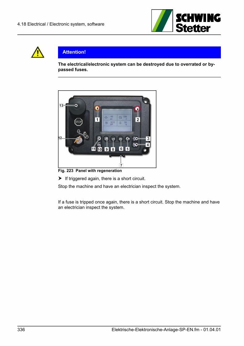
4.18 Electrical / Electronic system, software
ACHTUNG! Attention!
The electrical/electronic system can be destroyed due to overrated or by-passed fuses.
Fig. 223 Panel with regeneration
If triggered again, there is a short circuit.
Stop the machine and have an electrician inspect the system.
If a fuse is tripped once again, there is a short circuit. Stop the machine and have an electrician inspect the system.
336 Elektrische-Elektronische-Anlage-SP-EN.fm - 01.04.01
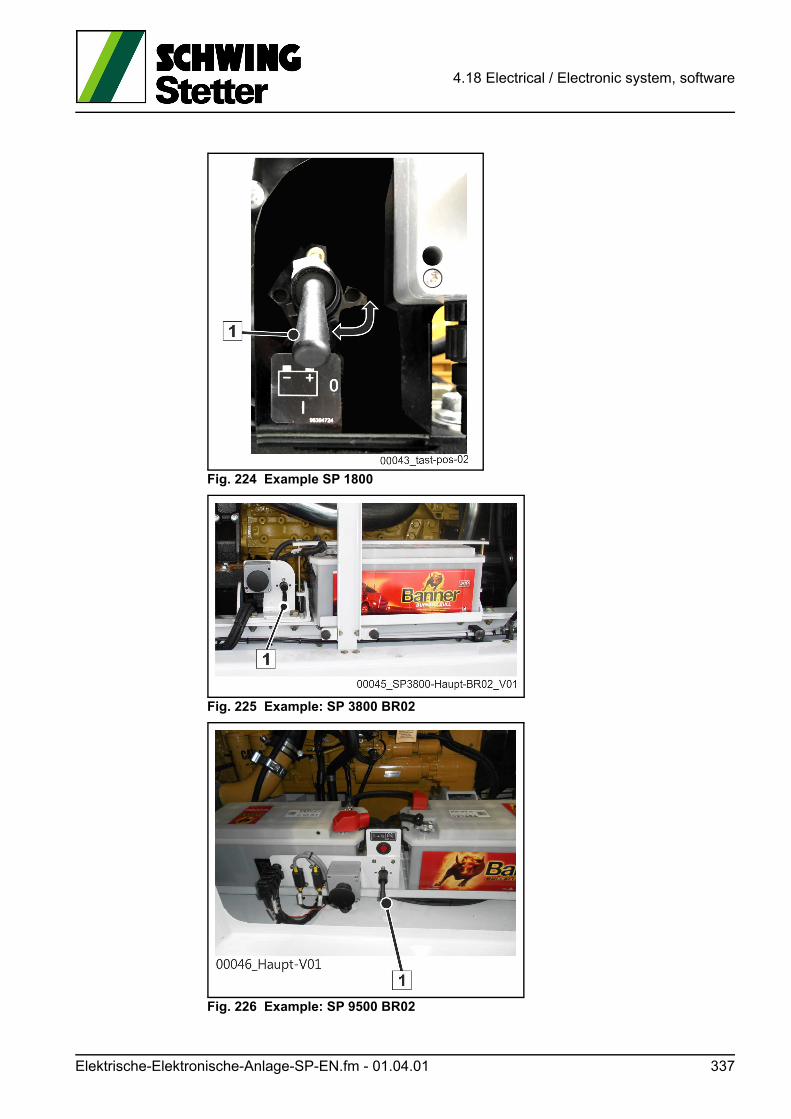
4.18 Electrical / Electronic system, software
Fig. 224 Example SP 1800
Fig. 225 Example: SP 3800 BR02
Fig. 226 Example: SP 9500 BR02
Elektrische-Elektronische-Anlage-SP-EN.fm - 01.04.01 337

4.18 Electrical / Electronic system, software
4.18.4 Working on electrical / electronic components
WARNUNG! Warning!
Only suitably qualified personnel may work on the electrical control and elec-tronics.
Unqualified interventions impair operational safety and result in the termination of the operating license and CE certification.
Before working on electrical or electronic components, disconnect:
1. First the negative lead (-).
2. Then the positive lead (+).
from the drive motor’s starter batteries. This is sufficient for preventing short circuits and protecting the SCHWING control unit.
Connect in reverse order.
ACHTUNG! Attention!
Risk of short circuit!
Do not place tools on batteries.
Further protective measures may be required for the vehicle electronics (e.g. for the anti-lock braking system ABS).
• Read the operating instructions of the engine manufacturer or vehicle manufac-turer to find out about how to protect its electronics.
• Do not touch live parts.
• Never check the voltage by touching the ground.
• Replace defective control lamps immediately.
• Never disconnect a cable from the starter batteries, alternator or regulator while the motor is running.
• Earth the machine to establish equipotential bonding between the machine and the ground.
338 Elektrische-Elektronische-Anlage-SP-EN.fm - 01.04.01
4.18 Electrical / Electronic system, software
4.18.5 Software
Only representatives of SCHWING are permitted to alter the machine’s software. This also applies to updates.
GEFAHR! Danger!
Unauthorised modifications to the software can result in serious damage and accidents.
SCHWING is not liable for the consequences of unauthorised software modifications.
4.18.6 Electrically powered machines
Have an electrician disconnect the power supply to such machines prior to carrying out repair work on the respective machine.
GEFAHR! Danger!
Danger caused by electric shock!
Only qualified electricians may work on the electrical system.
4.18.7 Electric welding procedure
See (chap. 4.20).
4.18.8 Jump starting
Connect the jumper cable as described in the operating instructions for the vehicle or the motor.
4.18.9 Jump starting stationary pumps with batteries connected in series
Machines can be supplied with 24V by two 12V batteries connected in series.
Observe the information below when jump starting due to the spatial separation of both batteries (e.g. one on the right-hand and one on the left-hand side of the ma-chine).
Connect the positive terminal of the machine battery (the battery is located near the starter motor) to the positive terminal of the donor unit using the red jump lead.
Next, attach the black jump lead to the negative terminal of the donor unit and then to the negative terminal of the machine battery (e.g. on the opposite side of the machine).
Elektrische-Elektronische-Anlage-SP-EN.fm - 01.04.01 339
4.18 Electrical / Electronic system, software
Make sure to observe the correct order!
Under no circumstances may the terminals of the batteries be connected the other way round.
If the engine starts, then the cables can be removed again in the reverse order.
A diesel engine uses considerably more power to start than a gasoline engine, which must be taken into account when selecting the donor unit. The jump lead should be made of high-quality copper cable in accordance with DIN 72553-25 and have a cross section of min. 35 mm².
4.18.10 Mechanical processes
Cover devices, cables etc. when drilling or grinding work etc. is to be carried out on the machine.
4.18.11 Painting and working with aggressive substances
Cover devices, cables etc. to protect them against paint mist and aggressive sub-stances.
4.18.12 Steam jet cleaning
Cover any electrical and electronic components.
Never direct a water or steam jet onto these components.
Any penetrating moisture leads to malfunctions and can destroy electronics and electrical components completely.
340 Elektrische-Elektronische-Anlage-SP-EN.fm - 01.04.01
4.18 Electrical / Electronic system, software
4.18.13 Starter batteries (lead-acid batteries)
GEFAHR! Danger!
Risk of explosion!
The gases discharged when charging the lead acid rechargeable batteries are highly explosive! Fire, sparks, smoking and naked lights are prohibited in the vicinity!
Danger of acid burns!
Wear protective glasses and protective gloves! Avoid any contact with skin and clothing!
Risk of short circuit!
Do not place tools on batteries!
ACHTUNG! Attention!
The following instructions do not apply to maintenance-free starter batteries.
Strictly observe the manufacturer instructions!
4.18.14 Checking the acid level
• Clean battery surface, open locking caps.
• The fluid should typically be 10 to 15 mm above the plates or at the level of the control device. Observe the manufacturer instructions.
• Refill with distilled water (not acid!), if necessary.
• Mount locking caps.
4.18.15 Checking the open-circuit voltage
In order to achieve a correct result, the battery may have been neither connected to a load nor charged at least two hours before the measurement.
If the open-circuit voltage is to be measured with a built-in battery, first disconnect the negative terminal and then the positive terminal from the battery. Otherwise, there is a danger of short circuiting!
• Measure the voltage between the terminals.
If the measuring device displays at least 12.5 volts, then the battery is in order. The battery must be charged immediately once below 12.5 volts.
Elektrische-Elektronische-Anlage-SP-EN.fm - 01.04.01 341

4.18 Electrical / Electronic system, software
4.18.16 Checking the acid density
Using a hydrometer (Fig. 227) measures the acid density of each individual cell. The acid temperature must be at least at 10 °C during this process.
The acid densities of the individual cells may not deviate by more than 0.03 kg/l. Otherwise, the battery is defective and must be replaced.
It should further be noted that the acid density is lower under tropical conditions. See (Table 2).
Fig. 227 Hydrometer
4.18.17 Charging the battery
Charge battery by running the motor for several hours or with a charger.
When charging with a charger, the battery must be at a temperature of at least 10 °C.
Disconnect both terminal posts from the battery.
Acid density (kg/l) Charging status Action
1.28 1.23 good -
1.20 1.12 half charged
1.12 1.08 empty charge immediately!
Table 2
342 Elektrische-Elektronische-Anlage-SP-EN.fm - 01.04.01
4.18 Electrical / Electronic system, software
Information
Always disconnect the negative terminal first and then the positive.
Otherwise, there is a risk of short circuiting!
Open locking cap.
Charging current max. 10 % of the battery capacity:
Stop charging after reaching an acid density of 1.28 kg/l or 1.23 kg/l (in the trop-ics) if the charger does not have an automatic regulator.
Check acid level and refill with distilled water, if necessary.
Clean battery terminals and terminal posts.
First connect the positive terminal and then the negative terminal. Otherwise, there is a risk of short circuiting! Only tighten terminal posts by hand.
Apply a thin layer of acid protective grease to the terminal posts.
4.18.18 Maintaining the batteries during machine downtimes
The following measures are necessary in order to prevent damage to the ma-chine’s batteries during long periods of downtime.
4.18.18.1 Downtime of 1 to 4 weeks
Disconnect the batteries (disconnect ground wires on the batteries and, if available, switch the battery main switch to pos. 0). This prevents the batteries from losing their charge due to quiescent current consumption.
4.18.18.2 Downtime of more than 4 weeks:
During downtimes of 4 weeks or more, the batteries must be removed and stored in a dry place at a temperature of 0 °C to 30 °C. The batteries must be stored stand-ing up. During this time, the battery voltage must be consistently kept at over 12.55 V. If the voltage of the battery falls below 12.1 V, this can cause damage and it has to be replaced.
Example: 120 Ah battery
Charging current max.: 12 ampere
Elektrische-Elektronische-Anlage-SP-EN.fm - 01.04.01 343
4.18 Electrical / Electronic system, software
Information
Please refer to the manufacturer specifications for further information on the starter batteries!
4.18.19 Storage and installation
Keep battery clean and dry in order to prevent discharge through leakage.
Ensure proper installation in the machine. Vibrations shorten the service life. Dam-age to the battery case entails high follow-up costs due to escaping acid.
4.18.20 Disposal
Turn in old batteries at a collection point. Observe regional regulations for disposal of batteries and sulphuric acid.
Information
Please refer to the operating instructions from the vehicle or engine manufacturer for further information on the starter batteries
344 Elektrische-Elektronische-Anlage-SP-EN.fm - 01.04.01
4.19 Safety inspections
4.19 Safety inspections
Alongside regular maintenance work, continuous observation and technical safety inspections are essential tools in maintaining operational and work safety with the machine and accessories.
As such, the responsibilities are as follows:
4.19.1 Machine operator
The machine operator is responsible for the visual and functional inspections of "his" machine, including accessories, before and during operation.
He must discontinue use of the machine if he/she discovers defects endangering work safety.
He/she is responsible for the external condition of "his/her" machine. As such, he/she must ensure e.g. the timely repair of damage to paintwork.
Especially on placing booms, corrosion pitting can lead to tears and breaks!
As the vehicle driver, he/she is responsible for the roadworthy condition of his/her vehicle, in the sense of local regulations in the country of use.
4.19.2 Competent person (specialist)
A competent person has to carry out the necessary technical safety inspections at regular intervals and record the results in the inspection book.
The definition of a competent person is given in the SAFETY MANUAL.
We recommend only contracting SCHWING employees to carry out this inspection.
4.19.3 Expert
An expert must be consulted in case of significant changes and extensive repairs (for example, if welding is carried out on load-bearing parts).
The definition of an expert is given in the SAFETY MANUAL.
4.19.4 Additional inspections
For certain units relevant to safety, such as accumulators, the relevant inspection regulations in the country of use must be observed.
If no qualified personnel are available, we highly recommend contracting a SCHWING employee to carry out the inspection.
Sicherheitspruefung-EN.fm - 01.07.01 345
4.19 Safety inspections
4.19.5 Technical safety inspection
As there is more risk of damage with older machines, the technical safety inspec-tion interval for concrete pumps and placing booms is dependant on the age of the machine.
That means that older machines must be more frequently checked than newer ones.
The respective inspection intervals are given in the SAFETY MANUAL.
Information
Test intervals
Adhering to these inspection intervals is imperative for increasing the service life and reducing repair costs!
Due to the dynamic loads that occur on all machines, over time fatigue can occur on steel parts, leading to cracks or fractures.
Of course other components also age, for example through environmental influenc-es, and should be checked regularly.
The older the machine, the higher the probability of damage.
Therefore the graded, regular technical safety inspection is an effective means for detecting damage at an early stage, before it leads to machine failure and (or) an accident.
Information
Case of damage!
Please be aware that in the event of damage, the question of whether the machine was checked regularly and correctly can be critical for assessing liability!
4.19.6 Safety components
If a defect is detected on a safety component during a technical safety inspection or on any other occasion, the machine must not be used until it is repaired.
As a rule, special skills are required to carry out repairs, which is why we strongly recommend contracting SCHWING’s customer service to perform this inspection.
If you carry out repairs on safety components yourself or hire a third party to do this, we encourage you to notify us of the damage and the work carried out.
You help us to improve our products and if necessary, initiate appropriate urgent measures.
For your notification you can use a copy of the form found on the next page.
346 Sicherheitspruefung-EN.fm - 01.07.01
4.19 Safety inspections
4.19.6.1 What are safety components?
The SCHWING factory standard distinguishes between safety components of the first (S1) and second order (S2).
The failure of S1 parts can pose a danger to life and limb. All persons inside the danger zone are in extreme danger of being killed.
S1 parts include, for example:
• Placing boom arms
• Levers and bolts on the placing boom
• Hydraulic cylinders on the boom and outrigger
• Outriggers
• EMERGENCY STOP parts and controls
Upon failure of S2 parts, primarily the main functions of the machine, such as "pumping concrete" or "distributing concrete", fail.
S2 parts include, for example:
• Hydraulic pumps
• Drives
• Gear
• Chutes
• Concrete filling hoppers
In practice, S1 and S2 components are often installed together. This makes it diffi-cult to clearly assess a component’s individual relevance to technical safety in the event of a failure.
It also always depends on the specific situation. Ruptured concrete pumping lines or hydraulic hoses, for example, can result in machine failure and can also endan-ger the lives and health of people located nearby!
Please also do not hesitate to inform us of damage of which the technical relevance is not immediately apparent.
In any case, you still help us to improve our products - and you are on the safe side.
In advance, we thank you very much for your help.
Please copy!
4.19.7 Notification of damage for safety components
Please complete the copy of this questionnaire and send the completed copy to:
SCHWING GmbHServicePO Box 20 03 62D-44647 Herne
Sicherheitspruefung-EN.fm - 01.07.01 347
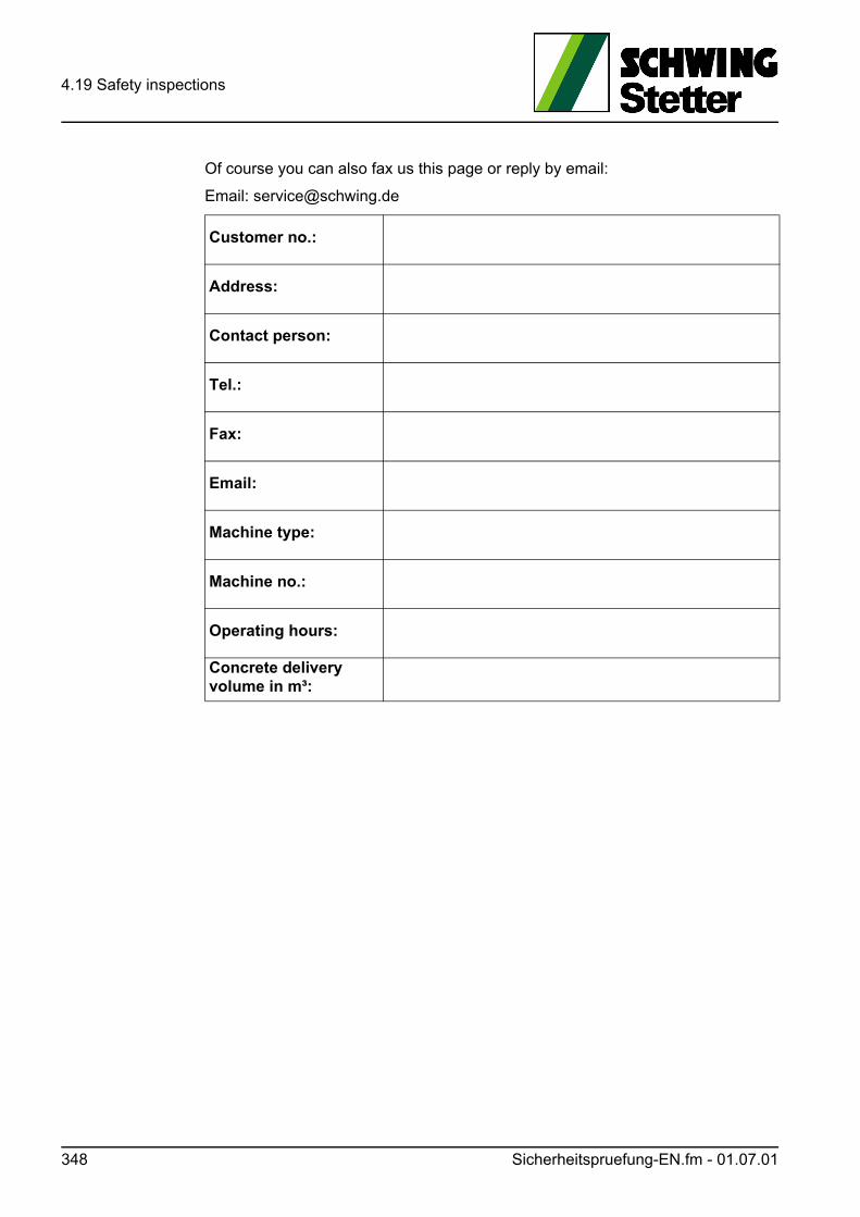
4.19 Safety inspections
Of course you can also fax us this page or reply by email:
Email: [email protected]
Customer no.:
Address:
Contact person:
Tel.:
Fax:
Email:
Machine type:
Machine no.:
Operating hours:
Concrete delivery volume in m³:
348 Sicherheitspruefung-EN.fm - 01.07.01
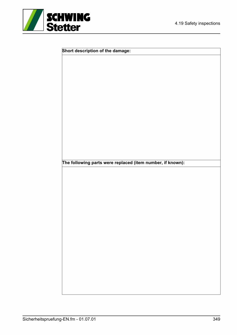
4.19 Safety inspections
Short description of the damage:
The following parts were replaced (item number, if known):
Sicherheitspruefung-EN.fm - 01.07.01 349
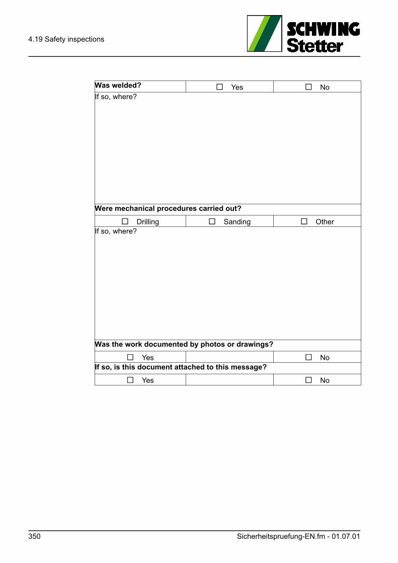
4.19 Safety inspections
Was welded? Yes NoIf so, where?
Were mechanical procedures carried out?
Drilling Sanding OtherIf so, where?
Was the work documented by photos or drawings?
Yes NoIf so, is this document attached to this message?
Yes No
350 Sicherheitspruefung-EN.fm - 01.07.01
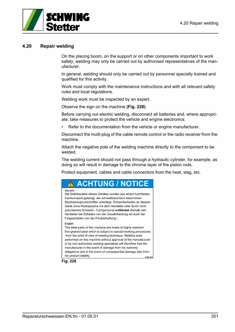
4.20 Repair welding
4.20 Repair welding
On the placing boom, on the support or on other components important to work safety, welding may only be carried out by authorised representatives of the man-ufacturer.
In general, welding should only be carried out by personnel specially trained and qualified for this activity.
Work must comply with the maintenance instructions and with all relevant safety rules and local regulations.
Welding work must be inspected by an expert.
Observe the sign on the machine (Fig. 228)
Before carrying out electric welding, disconnect all batteries and, where appropri-ate, take measures to protect the vehicle and engine electronics.
• Refer to the documentation from the vehicle or engine manufacturer.
Disconnect the multi-plug of the cable remote control or the radio receiver from the machine.
Attach the negative pole of the welding machine directly to the component to be welded.
The welding current should not pass through a hydraulic cylinder, for example, as doing so will result in damage to the chrome layer of the piston rods.
Protect equipment, cables and cable connectors from the heat, slag, etc.
Fig. 228
Reparaturschweissen-EN.fm - 01.05.01 351

4.20 Repair welding
352 Reparaturschweissen-EN.fm - 01.05.01

Trennblatt_Kapitel-Fernsteueru
5 Remote control
ng-EN.fm 353

5 Remote control
354 Trennblatt_Kapitel-Fernsteuerung-EN.fm - 01.00.00
OPERATING INSTRUCTIONS
®
Receiver Type / Version
Factory No.
Frequency
Transmitter Type / Version
Factory No.
Frequency
X XX
Planar-V4
Compact-M, Compact-V
R-18, R-CAN
Compact-M2
R6, R10
%
%
%
Portable transmitter.Receiver with integrated mounting holes.Multi-pin connecting cable for the receiver according to your specifications.
For explanatory notes on obtaining an operating permit please refer to registration docu-ments enclosed in the appendix of this operating instruction. Observe all applicable work-safety and accident prevention regulations carefully. Only fully trained, authorized per-sonnel may use the NBB radio control equipment. Components, etc. built into the NBBequipment for safety purposes must be regularly inspected.
Failure to observe these recommendations will put both you yourself and others at risk.Under these circumstances, NBB rescinds the guarantee and any other form of liability.This radio control unit is designed exclusively for the control of construction machinesand industrial plants. Only under these conditions are the safety systems (STOP and zerosetting) fully effective. No other form of use is permitted. Any non-observance of this con-dition will relieve NBB of all liability.
The actual delivery specification is as detailed on the confirmation of order or
the delivery note accompanying the goods!
Even if you are accustomed to working with radio control systems, read these
operating instructions carefully before using this equipment. Only this docu-
ment contains the latest information relating to your NBB radio control system.
If the NBB radio control unit develops a fault, it must be shut down immediately.
The transmitter should be switched off with the STOP key. The connecting cable
must be disconnected at the receiver from the connecting socket (terminal) of
the unit to be controlled . The repair of the equipment must not be carried out ot-
her than by NBB or an NBB authorized technician.
1. STANDARD SPECIFICATION
2. SAFETY PRECAUTIONS
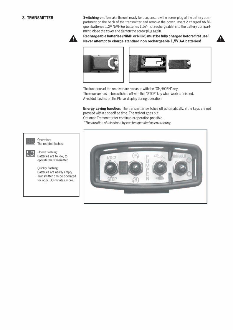
3. TRANSMITTER Switching on: To make the unit ready for use, unscrew the screw plug of the battery com-partment on the back of the transmitter and remove the cover. Insert 2 charged AA Mi-gnon batteries 1,2V NiMH (or batteries 1,5V - not rechargeable) into the battery compart-ment, close the cover and tighten the screw plug again.Rechargeable batteries (NiMH or NiCd) must be fully charged before first use
Never attempt to charge standard non rechargeable AA batteries
!
1,5V !
The functions of the receiver are released with the “ON/HORN” key.The receiver has to be switched off with the "STOP" key when work is finished.A red dot flashes on the Planar display during operation.
The transmitter switches off automatically, if the keys are notpressed within a specified time. The red dot goes out.Optional: Transmitter for continuous operation possible.
Energy saving function:
*The duration of this stand-by can be specified when ordering.
Operation:The red dot flashes.
Slowly flashing:Batteries are to low, tooperate the transmitter.
Quickly flashing:Batteries are nearly empty.Transmitter can be operatedfor appr. 30 minutes more.
o.L
8.8
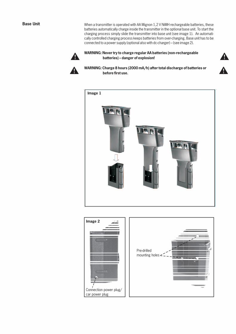
Base Unit When a transmitter is operated with AA Mignon 1,2 V NiMH rechargeable batteries, thesebatteries automatically charge inside the transmitter in the optional base unit. To start thecharging process simply slide the transmitter into base unit (see image 1). An automati-cally controlled charging process keeps batteries from over-charging. Base unit has to beconnected to a power supply (optional also with dc-charger) – (see image 2).
WARNING: Never try to charge regular AA batteries (non-rechargeable
batteries) – danger of explosion!
WARNING: Charge 8 hours (2000 mA/h) after total discharge of batteries or
before first use.
Pre-drilledmounting holes
Connection power plug/car power plug
Image 2
Image 1
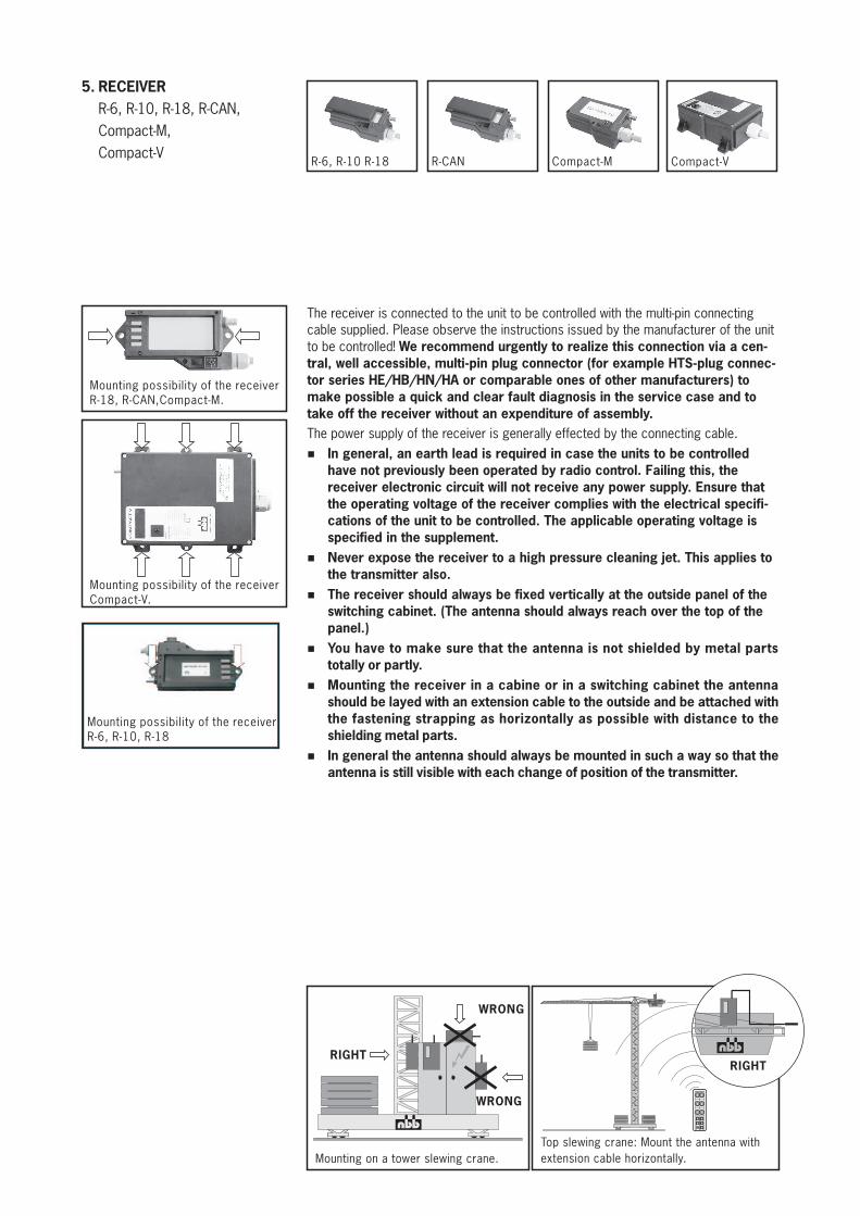
5. RECEIVER
R-6, R-10, R-18, R-CAN,
Compact-M,
Compact-V
Mounting possibility of the receiverR-18, R-CAN,Compact-M.
Mounting possibility of the receiverCompact-V.
.
WRONG
Mounting on a tower slewing crane.Top slewing crane: Mount the antenna withextension cable horizontally.
RIGHT
The receiver is connected to the unit to be controlled with the multi-pin connectingcable supplied. Please observe the instructions issued by the manufacturer of the unitto be controlled!
The power supply of the receiver is generally effected by the connecting cable.
We recommend urgently to realize this connection via a cen-
tral, well accessible, multi-pin plug connector (for example HTS-plug connec-
tor series HE/HB/HN/HA or comparable ones of other manufacturers) to
make possible a quick and clear fault diagnosis in the service case and to
take off the receiver without an expenditure of assembly.
In general, an earth lead is required in case the units to be controlled
have not previously been operated by radio control. Failing this, the
receiver electronic circuit will not receive any power supply. Ensure that
the operating voltage of the receiver complies with the electrical specifi-
cations of the unit to be controlled. The applicable operating voltage is
specified in the supplement.
Never expose the receiver to a high pressure cleaning jet. This applies to
the transmitter also.
The receiver should always be fixed vertically at the outside panel of the
switching cabinet. (The antenna should always reach over the top of the
panel.)
You have to make sure that the antenna is not shielded by metal parts
totally or partly.
Mounting the receiver in a cabine or in a switching cabinet the antenna
should be layed with an extension cable to the outside and be attached with
the fastening strapping as horizontally as possible with distance to the
shielding metal parts.
In general the antenna should always be mounted in such a way so that the
antenna is still visible with each change of position of the transmitter.
%
%
%
%
%
%
WRONG
RIGHT
Compact-MR-6, R-10 R-18 R-CAN Compact-V
Mounting possibility of the receiverR-6, R-10, R-18
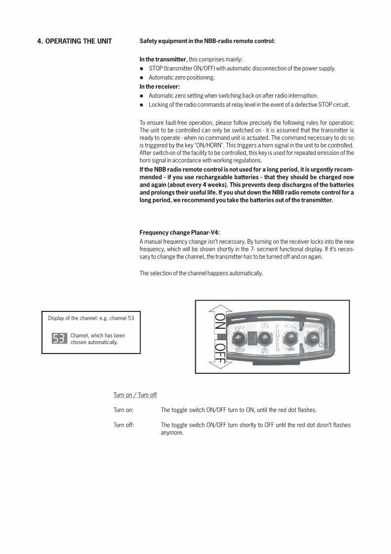
4. OPERATING THE UNIT Safety equipment in the NBB-radio remote control:
In the transmitter
In the receiver:
If the NBB radio remote control is not used for a long period, it is urgently recom-
mended - if you use rechargeable batteries - that they should be charged now
and again (about every 4 weeks). This prevents deep discharges of the batteries
and prolongs their useful life. If you shut down the NBB radio remote control for a
long period, we recommend you take the batteries out of the transmitter.
Frequency change Planar-V4:
, this comprises mainly:
STOP (transmitter ON/OFF) with automatic disconnection of the power supply.
Automatic zero positioning.
Automatic zero setting when switching back on after radio interruption.
Locking of the radio commands at relay level in the event of a defective STOP circuit.
To ensure fault-free operation, please follow precisely the following rules for operation:The unit to be controlled can only be switched on - it is assumed that the transmitter isready to operate - when no command unit is actuated. The command necessary to do sois triggered by the key "ON/HORN". This triggers a horn signal in the unit to be controlled.After switch-on of the facility to be controlled, this key is used for repeated emission of thehorn signal in accordance with working regulations.
A manual frequency change isn’t necessary. By turning on the receiver locks into the newfrequency, which will be shown shortly in the 7- secment functional display. If it’s neces-sary to change the channel, the transmitter has to be turned off and on again.
The selection of the channel happens automatically.
%
%
%
%
Display of the channel: e.g. channel 53
Channel, which has beenchosen automatically.
Turn on / Turn off
Turn on: The toggle switch ON/OFF turn to ON, until the red dot flashes.
Turn off: The toggle switch ON/OFF turn shortly to OFF until the red dot dosn’t flashesanymore.
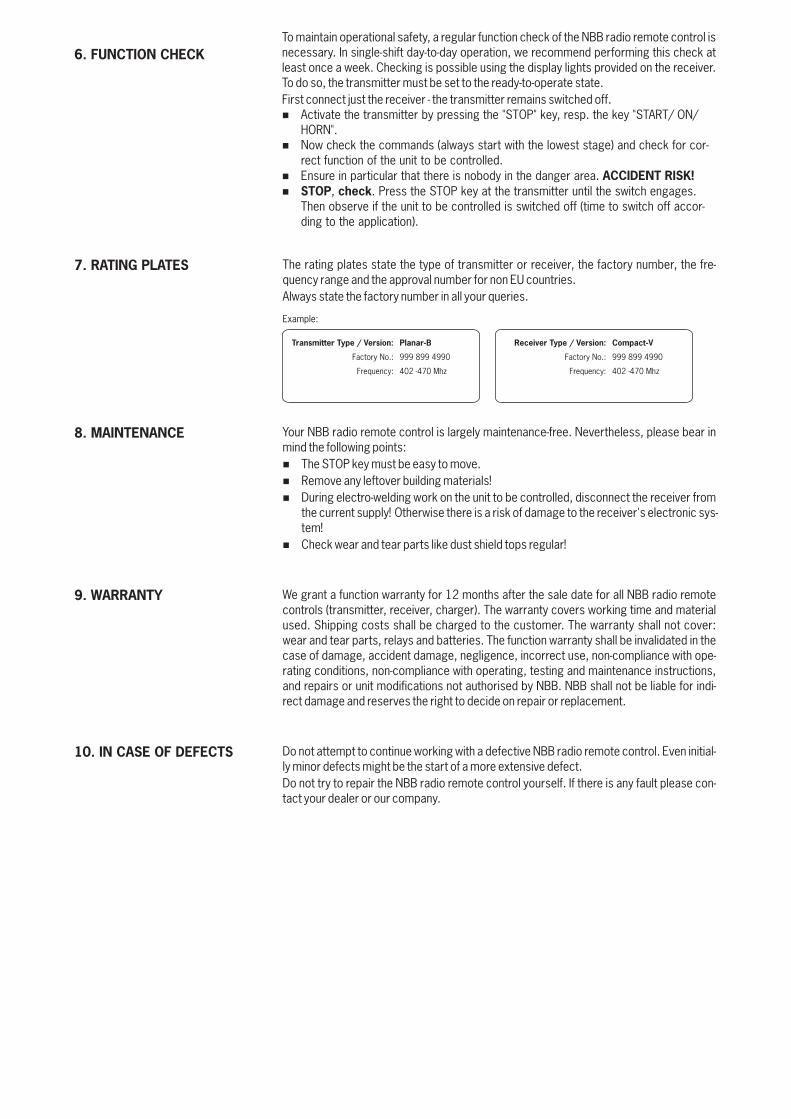
The rating plates state the type of transmitter or receiver, the factory number, the fre-quency range and the approval number for non EU countries.Always state the factory number in all your queries.
Your NBB radio remote control is largely maintenance-free. Nevertheless, please bear inmind the following points:
The STOP key must be easy to move.Remove any leftover building materials!During electro-welding work on the unit to be controlled, disconnect the receiver fromthe current supply! Otherwise there is a risk of damage to the receiver's electronic sys-tem!Check wear and tear parts like dust shield tops regular!
We grant a function warranty for 12 months after the sale date for all NBB radio remotecontrols (transmitter, receiver, charger). The warranty covers working time and materialused. Shipping costs shall be charged to the customer. The warranty shall not cover:wear and tear parts, relays and batteries. The function warranty shall be invalidated in thecase of damage, accident damage, negligence, incorrect use, non-compliance with ope-rating conditions, non-compliance with operating, testing and maintenance instructions,and repairs or unit modifications not authorised by NBB. NBB shall not be liable for indi-rect damage and reserves the right to decide on repair or replacement.
Do not attempt to continue working with a defective NBB radio remote control. Even initial-ly minor defects might be the start of a more extensive defect.Do not try to repair the NBB radio remote control yourself. If there is any fault please con-tact your dealer or our company.
%
%
%
%
10. IN CASE OF DEFECTS
9. WARRANTY
8. MAINTENANCE
7. RATING PLATES
Example:
X X
Transmitter Type / Version:
Factory No.:
Frequency:
Planar-B
999 899 4990
402 -470 Mhz
X
Receiver Type / Version:
Factory No.:
Frequency:
Compact-V
999 899 4990
402 -470 Mhz
To maintain operational safety, a regular function check of the NBB radio remote control isnecessary. In single-shift day-to-day operation, we recommend performing this check atleast once a week. Checking is possible using the display lights provided on the receiver.To do so, the transmitter must be set to the ready-to-operate state.First connect just the receiver - the transmitter remains switched off.
Activate the transmitter by pressing the "STOP" key, resp. the key "START/ ON/HORN".Now check the commands (always start with the lowest stage) and check for cor-rect function of the unit to be controlled.Ensure in particular that there is nobody in the danger area.
, . Press the STOP key at the transmitter until the switch engages.Then observe if the unit to be controlled is switched off (time to switch off accor-ding to the application).
%
%
%
%
ACCIDENT RISK!
STOP check
6. FUNCTION CHECK
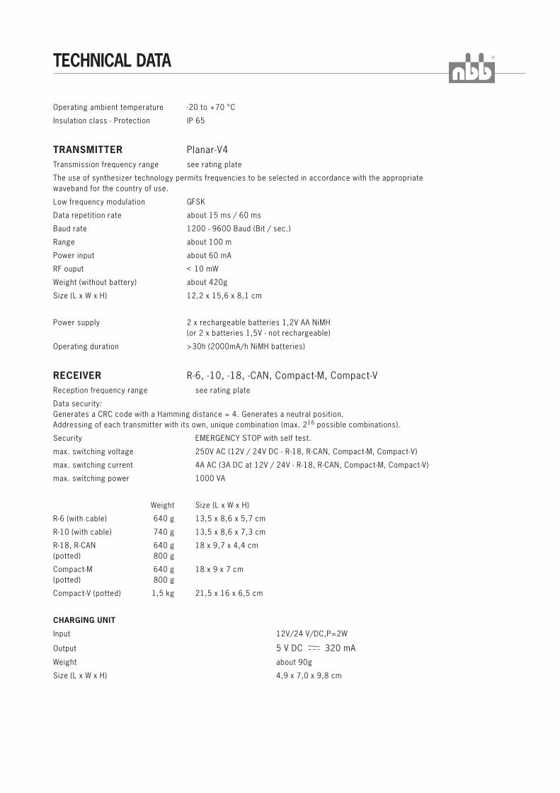
®TECHNICAL DATA
Operating ambient temperature -20 to +70 °C
Insulation class - Protection IP 65
Transmission frequency range see r
The use of synthesizer technology permits frequencies to be selected in accordance with the appropriatewaveband for the country of use.
Low frequency modulation GFSK
Data repetition rate about 15 ms / 60 ms
Baud rate
Range about 100 m
Power input about
RF ouput <
Weight (without battery) about 420g
Size (L x W x H) 12,2 x 15,6 x 8,1 cm
TRANSMITTER Planar-V4
ating plate
1200 - 9600 Baud (Bit / sec.)
60 mA
10 mW
Power supply 2 x rechargeable batteries 1,2V AA NiMH(or 2 x batteries 1,5V - not rechargeable)
Operating duration >30h (2000mA/h NiMH batteries)
Reception frequency range see rating plate
Data security:Generates a CRC code with a Hamming distance = 4. Generates a neutral position.Addressing of each transmitter with its own, unique combination (max. 2 possible combinations).
Security EMERGENCY STOP with self test.
max. switching voltage 250V AC (12V / 24V DC - R-18, R-CAN, Compact-M, Compact-V)
max. switching current 4A AC (3A DC at 12V / 24V - R-18, R-CAN, Compact-M, Compact-V)
max. switching power 1000 VA
Weight Size (L x W x H)
R-6 (with cable) 640 g 13,5 x 8,6 x 5,7 cm
R-10 (with cable) 740 g 13,5 x 8,6 x 7,3 cm
R-18, R-CAN 640 g 18 x 9,7 x 4,4 cm(potted) 800 g
Compact-M 640 g 18 x 9 x 7 cm(potted) 800 g
Compact-V (potted) 1,5 kg 21,5 x 16 x 6,5 cm
Input 12V/24 V/DC,P=2W
Output
Weight about 90g
Size (L x W x H) 4,9 x 7,0 x 9,8 cm
RECEIVER R-6, -10, -18, -CAN, Compact-M, Compact-V
16
CHARGING UNIT
5 V DC 320 mA
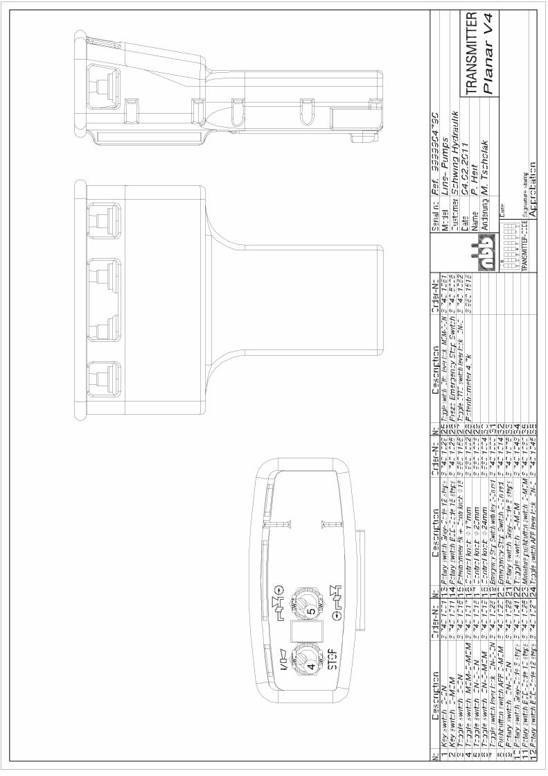
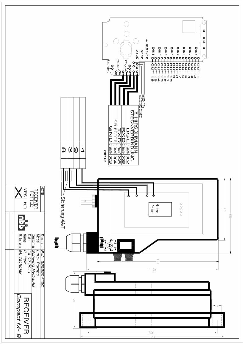
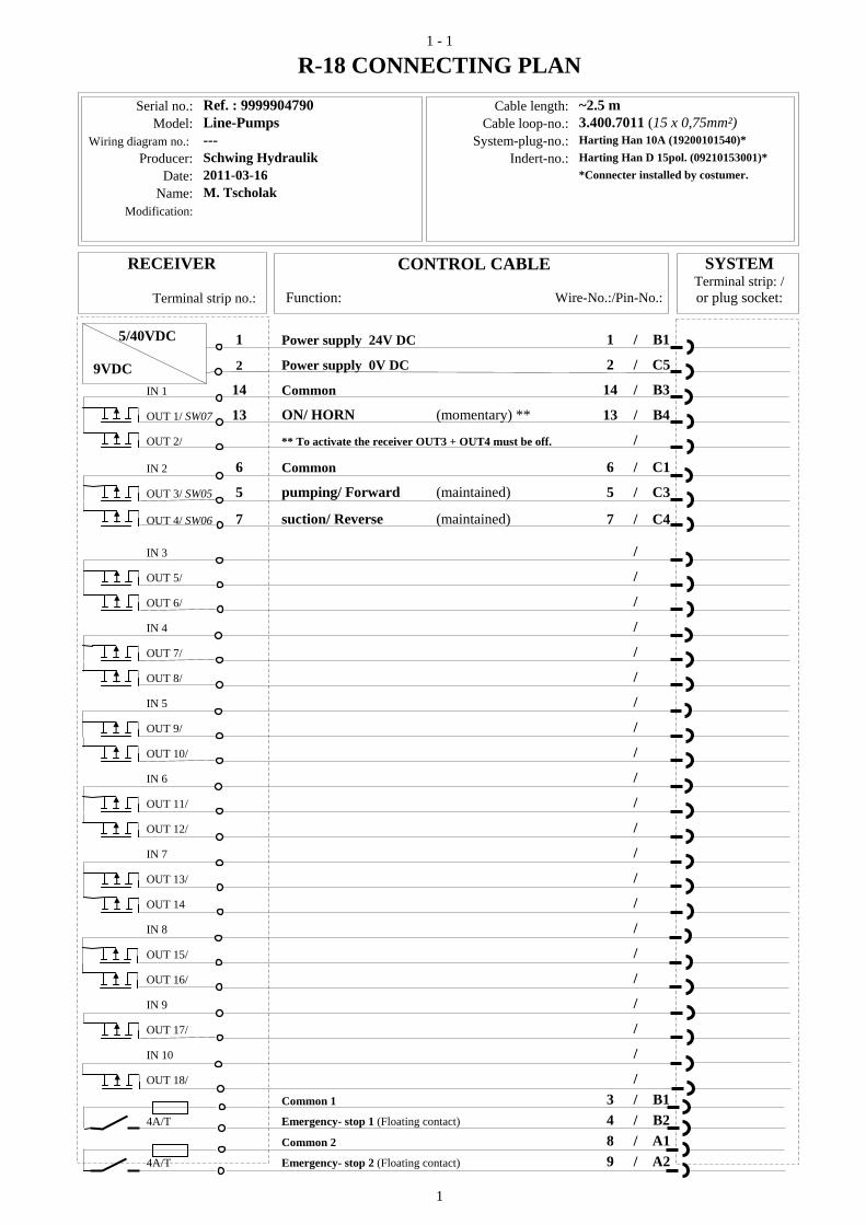
1 - 1
1
9VDC
5/40VDC
R-18 CONNECTING PLAN
Serial no.: Ref. : 9999904790 Cable length: ~2.5 m Model: Line-Pumps Cable loop-no.: 3.400.7011 (15 x 0,75mm²)
Wiring diagram no.: --- System-plug-no.: Harting Han 10A (19200101540)* Producer: Schwing Hydraulik Indert-no.: Harting Han D 15pol. (09210153001)*
Date: 2011-03-16 *Connecter installed by costumer. Name: M. Tscholak
Modification:
RECEIVER CONTROL CABLE SYSTEM
Terminal strip: /Terminal strip no.: Function: Wire-No.:/Pin-No.: or plug socket:
1 Power supply 24V DC 1 / B1
2 Power supply 0V DC 2 / C5
IN 1 14 Common 14 / B3
OUT 1/ SW07 13 ON/ HORN (momentary) ** 13 / B4
OUT 2/ ** To activate the receiver OUT3 + OUT4 must be off. /
IN 2 6 Common 6 / C1
OUT 3/ SW05 5 pumping/ Forward (maintained) 5 / C3
OUT 4/ SW06 7 suction/ Reverse (maintained) 7 / C4
IN 3 /
OUT 5/ /
OUT 6/ /
IN 4 /
OUT 7/ /
OUT 8/ /
IN 5 /
OUT 9/ /
OUT 10/ /
IN 6 /
OUT 11/ /
OUT 12/ /
IN 7 /
OUT 13/ /
OUT 14 /
IN 8 /
OUT 15/ /
OUT 16/ /
IN 9 /
OUT 17/ /
IN 10 /
OUT 18/ /
Common 1 3 / B1 4A/T Emergency- stop 1 (Floating contact) 4 / B2
Common 2 8 / A1 4A/T Emergency- stop 2 (Floating contact) 9 / A2

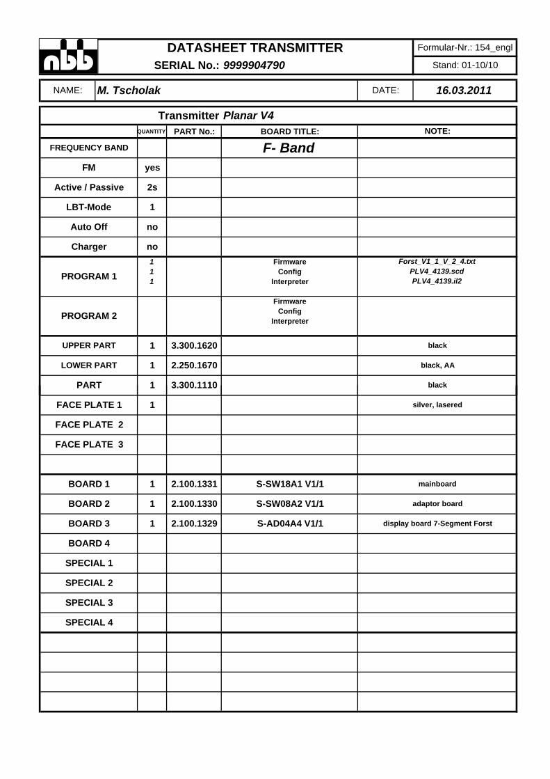
QUANTITY PART No.: BOARD TITLE:
1 Firmware1 Config1 Interpreter
FirmwareConfig
Interpreter
LOWER PART 1 2.250.1670 black, AA
PART 1 3.300.1110 black
PROGRAM 2
UPPER PART 1 3.300.1620 black
Charger no
PROGRAM 1Forst_V1_1_V_2_4.txt
PLV4_4139.scdPLV4_4139.il2
LBT-Mode 1
Auto Off no
FM yes
Active / Passive 2s
Transmitter Planar V4NOTE:
FREQUENCY BAND F- Band
DATASHEET TRANSMITTER Formular-Nr.: 154_engl
SERIAL No.: 9999904790 Stand: 01-10/10
NAME: M. Tscholak DATE: 16.03.2011
SPECIAL 3
SPECIAL 4
SPECIAL 1
SPECIAL 2
BOARD 3 1 2.100.1329 S-AD04A4 V1/1 display board 7-Segment Forst
BOARD 4
BOARD 1 1 2.100.1331 S-SW18A1 V1/1 mainboard
BOARD 2 1 2.100.1330 S-SW08A2 V1/1 adaptor board
FACE PLATE 3
FACE PLATE 1 1 silver, lasered
FACE PLATE 2
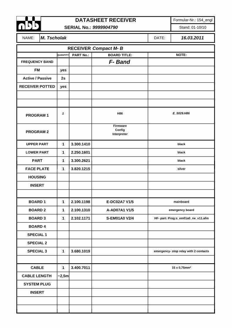
QUANTITY PART No.: BOARD TITLE:
1 H86
FirmwareConfig
Interpreter
LOWER PART 1 2.250.1601 black
PART 1 3.300.2621 black
PROGRAM 2
UPPER PART 1 3.300.1410 black
PROGRAM 1 E_5029.H86
RECEIVER POTTED yes
FM yes
Active / Passive 2s
RECEIVER Compact M- BNOTE:
FREQUENCY BAND F- Band
DATASHEET RECEIVER Formular-Nr.: 154_engl
SERIAL No.: 9999904790 Stand: 01-10/10
NAME: M. Tscholak DATE: 16.03.2011
SYSTEM PLUG
INSERT
CABLE 1 3.400.7011 15 x 0,75mm²
CABLE LENGTH ~2,5m
SPECIAL 3 1 3.680.1019 emergency- stop relay with 2 contacts
SPECIAL 1
SPECIAL 2
BOARD 3 1 2.102.1171 S-EM01A0 V2/4 HF- part: Prog:s_em01a0_rw_v11.afm
BOARD 4
BOARD 1 1 2.100.1198 E-DC02A7 V1/5 mainboard
BOARD 2 1 2.100.1310 A-AD07A1 V1/5 emergency board
INSERT
FACE PLATE 1 3.820.1215 silver
HOUSING


®
Bedienungsanleitungenglisch, Teile-Nr. 3.150.1340, Stand 07.11
Planar-V4, R-18, R-CAN, Compact-M, Compact-V
APPROVALS AND CERTIFICATES
© NBB Controls + Components GmbHOtto-Hahn-Straße 3-5DE-75248 Ölbronn-DürrnTel.: 0 72 37 / 9 99 - 0Fax: 0 72 37 / 9 99 - 1 99eMail: sales @nbb.dehttp://www.nbb.de
We reserve the right to alter specifications without notice.
Approvals EU countries:
EC Declaration of Conformity
M-Zert mbH
X X
Enclosure:
Obtainable at demand:
Certificate DIN EN ISO 9001:2008 No. 03022
Trennblatt_Kapitel-Sonderauss
6 Special equipment
Please note that the possibility to use special equipment depends on the machine model.
tattung-EN.fm 357

6 Special equipment
358 Trennblatt_Kapitel-Sonderausstattung-EN.fm -
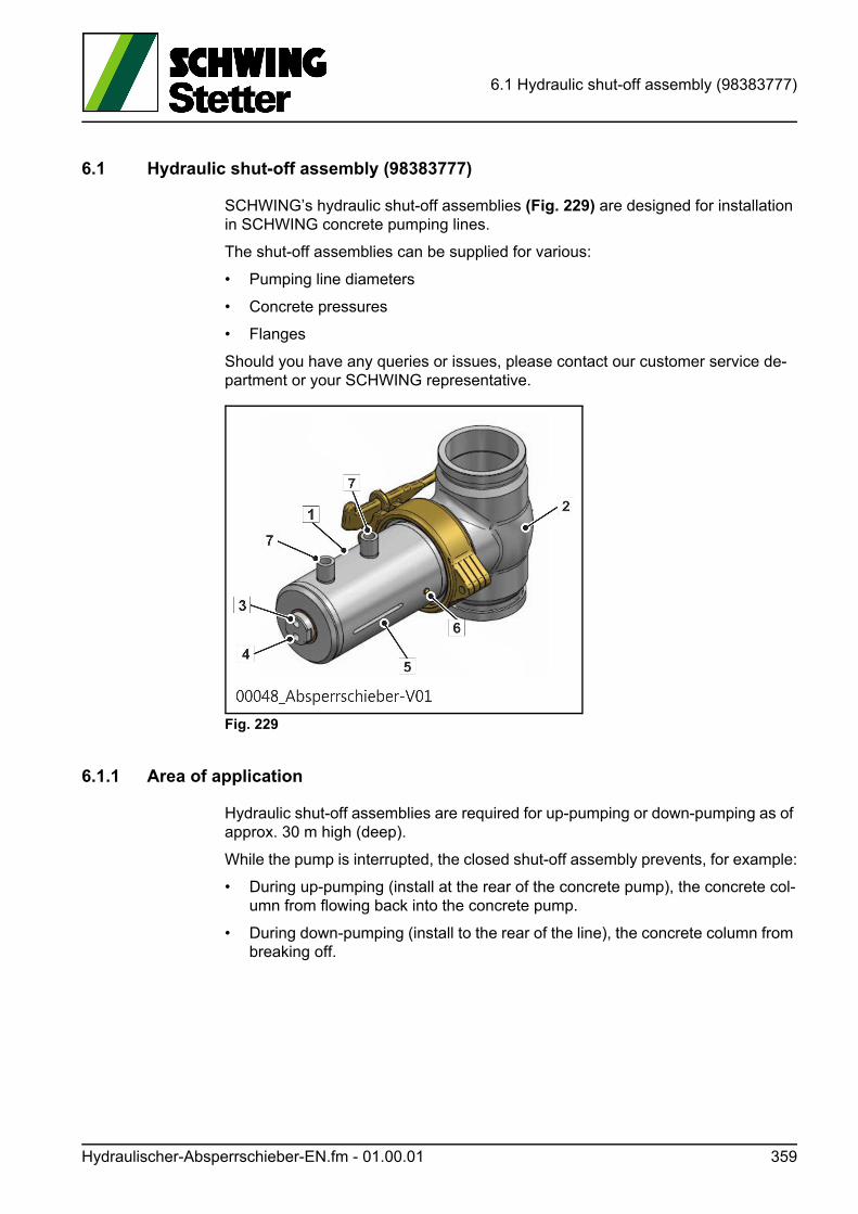
6.1 Hydraulic shut-off assembly (98383777)
6.1 Hydraulic shut-off assembly (98383777)
SCHWING’s hydraulic shut-off assemblies (Fig. 229) are designed for installation in SCHWING concrete pumping lines.
The shut-off assemblies can be supplied for various:
• Pumping line diameters
• Concrete pressures
• Flanges
Should you have any queries or issues, please contact our customer service de-partment or your SCHWING representative.
Fig. 229
6.1.1 Area of application
Hydraulic shut-off assemblies are required for up-pumping or down-pumping as of approx. 30 m high (deep).
While the pump is interrupted, the closed shut-off assembly prevents, for example:
• During up-pumping (install at the rear of the concrete pump), the concrete col-umn from flowing back into the concrete pump.
• During down-pumping (install to the rear of the line), the concrete column from breaking off.
Hydraulischer-Absperrschieber-EN.fm - 01.00.01 359
6.1 Hydraulic shut-off assembly (98383777)
6.1.2 Safety
Read through these operating instructions carefully before the initial commission-ing. Only begin with the work when you have understood everything.
Should you have any doubts or queries, never begin to work!
In case of danger, actuate an EMERGENCY-OFF button on the machine.
WARNUNG! Warning!
Malfunctions while pressure cleaning the pumping lines are dangerous!
• Only authorised persons (experts) may operate the shut-off assembly.
• The pumping line must only be opened when pressure free.
• The machine operator is responsible for ensuring that no unauthorised persons access the immediate vicinity of the shut-off assembly or associated control el-ements.
• Persons not involved must leave the danger area of the shut-off assembly.
• During the cleaning process, no one must be at the end of the line in the area of the concrete output.
• Make sure to read (chap. 3.18).
• Do not use the shut-off assembly under any circumstances to push out clogs!
360 Hydraulischer-Absperrschieber-EN.fm - 01.00.01
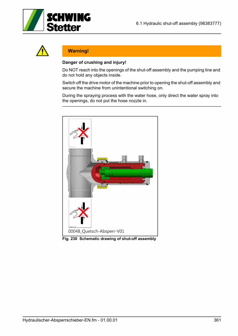
6.1 Hydraulic shut-off assembly (98383777)
WARNUNG! Warning!
Danger of crushing and injury!
Do NOT reach into the openings of the shut-off assembly and the pumping line and do not hold any objects inside.
Switch off the drive motor of the machine prior to opening the shut-off assembly and secure the machine from unintentional switching on.
During the spraying process with the water hose, only direct the water spray into the openings, do not put the hose nozzle in.
Fig. 230 Schematic drawing of shut-off assembly
Hydraulischer-Absperrschieber-EN.fm - 01.00.01 361
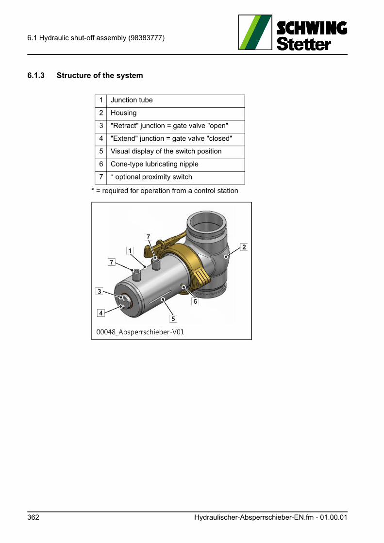
6.1 Hydraulic shut-off assembly (98383777)
6.1.3 Structure of the system
* = required for operation from a control station
1 Junction tube
2 Housing
3 "Retract" junction = gate valve "open"
4 "Extend" junction = gate valve "closed"
5 Visual display of the switch position
6 Cone-type lubricating nipple
7 * optional proximity switch
362 Hydraulischer-Absperrschieber-EN.fm - 01.00.01
6.1 Hydraulic shut-off assembly (98383777)
6.1.4 Installation
The shut-off assembly is installed in the pumping line using two couplings.
WARNUNG! Warning!
The use and insertion of materials other than those supplied by Schwing re-sult in the loss of operational safety and thus automatically in the loss of op-erational approval!
Only use original SCHWING couplings and spare parts.
6.1.5 Drive
Hydraulic shut-off assemblies can be connected to the concrete pump’s hydraulic system and actuated via a separate aggregate or hand pump.
WARNUNG! Warning!
Do NOT operate the shut-off assembly when it is not visible.
If required, a second person should be present.
6.1.6 Maintenance
Depending on the operating conditions, the shut-off assembly must be lubricated at least once a week with grease (grease nipple). As the lubrication requirement increases with progressive wear, the lubricating intervals must be shortened ac-cordingly.
6.1.7 Technical data
Closing volume: 0.63 l
Opening volume: 0.38 l
Stroke: 125 mm
Piston diameter: 80 mm
Piston rod diameter: 50 mm
P max. hydr.: 200 bar
Hydraulischer-Absperrschieber-EN.fm - 01.00.01 363

6.1 Hydraulic shut-off assembly (98383777)
364 Hydraulischer-Absperrschieber-EN.fm - 01.00.01
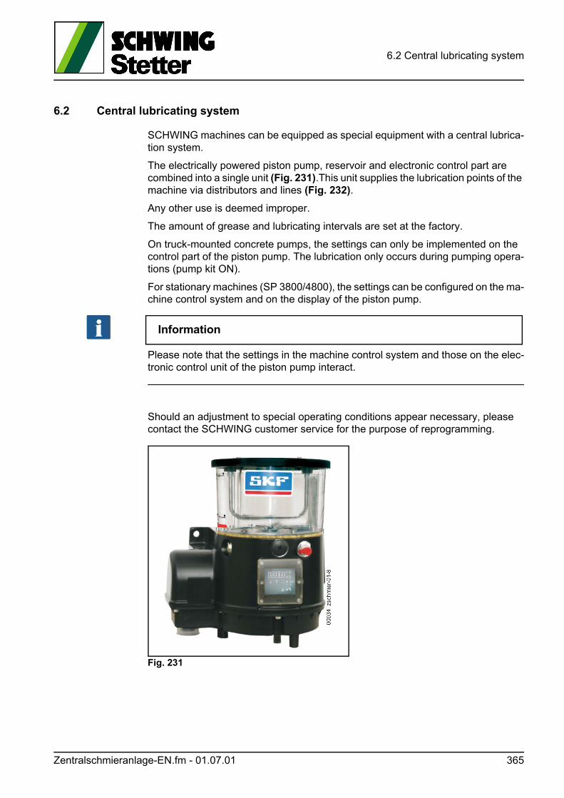
6.2 Central lubricating system
6.2 Central lubricating system
SCHWING machines can be equipped as special equipment with a central lubrica-tion system.
The electrically powered piston pump, reservoir and electronic control part are combined into a single unit (Fig. 231).This unit supplies the lubrication points of the machine via distributors and lines (Fig. 232).
Any other use is deemed improper.
The amount of grease and lubricating intervals are set at the factory.
On truck-mounted concrete pumps, the settings can only be implemented on the control part of the piston pump. The lubrication only occurs during pumping opera-tions (pump kit ON).
For stationary machines (SP 3800/4800), the settings can be configured on the ma-chine control system and on the display of the piston pump.
Information
Please note that the settings in the machine control system and those on the elec-tronic control unit of the piston pump interact.
Should an adjustment to special operating conditions appear necessary, please contact the SCHWING customer service for the purpose of reprogramming.
Fig. 231
Zentralschmieranlage-EN.fm - 01.07.01 365
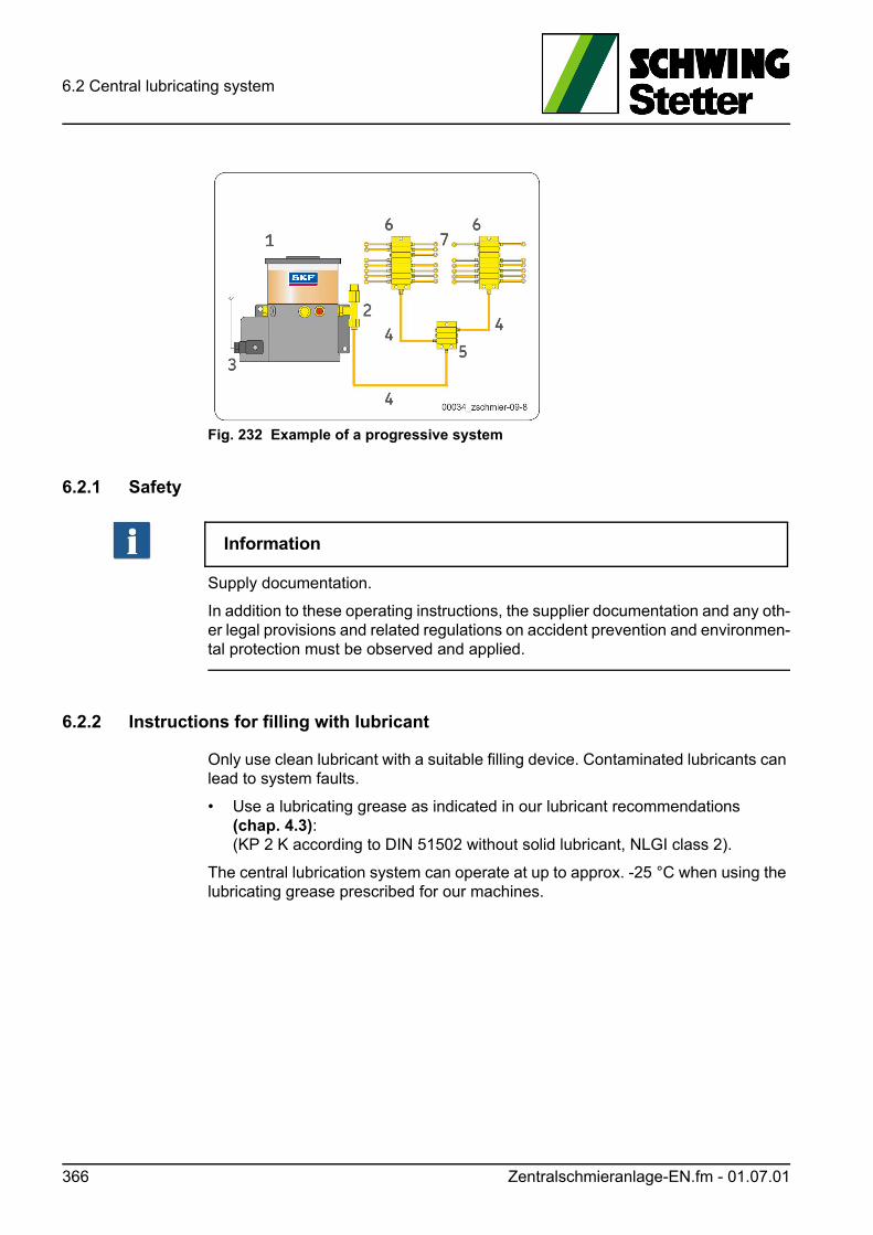
6.2 Central lubricating system
Fig. 232 Example of a progressive system
6.2.1 Safety
Information
Supply documentation.
In addition to these operating instructions, the supplier documentation and any oth-er legal provisions and related regulations on accident prevention and environmen-tal protection must be observed and applied.
6.2.2 Instructions for filling with lubricant
Only use clean lubricant with a suitable filling device. Contaminated lubricants can lead to system faults.
• Use a lubricating grease as indicated in our lubricant recommendations (chap. 4.3): (KP 2 K according to DIN 51502 without solid lubricant, NLGI class 2).
The central lubrication system can operate at up to approx. -25 °C when using the lubricating grease prescribed for our machines.
366 Zentralschmieranlage-EN.fm - 01.07.01
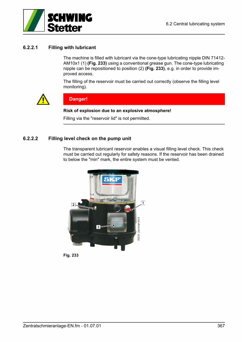
6.2 Central lubricating system
6.2.2.1 Filling with lubricant
The machine is filled with lubricant via the cone-type lubricating nipple DIN 71412-AM10x1 (1) (Fig. 233) using a conventional grease gun. The cone-type lubricating nipple can be repositioned to position (2) (Fig. 233), e.g. in order to provide im-proved access.
The filling of the reservoir must be carried out correctly (observe the filling level monitoring).
GEFAHR! Danger!
Risk of explosion due to an explosive atmosphere!
Filling via the "reservoir lid" is not permitted.
6.2.2.2 Filling level check on the pump unit
The transparent lubricant reservoir enables a visual filling level check. This check must be carried out regularly for safety reasons. If the reservoir has been drained to below the "min" mark, the entire system must be vented.
Fig. 233
Zentralschmieranlage-EN.fm - 01.07.01 367
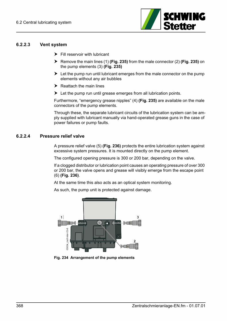
6.2 Central lubricating system
6.2.2.3 Vent system
Fill reservoir with lubricant
Remove the main lines (1) (Fig. 235) from the male connector (2) (Fig. 235) on the pump elements (3) (Fig. 235)
Let the pump run until lubricant emerges from the male connector on the pump elements without any air bubbles
Reattach the main lines
Let the pump run until grease emerges from all lubrication points.
Furthermore, “emergency grease nipples” (4) (Fig. 235) are available on the male connectors of the pump elements.
Through these, the separate lubricant circuits of the lubrication system can be am-ply supplied with lubricant manually via hand-operated grease guns in the case of power failures or pump faults.
6.2.2.4 Pressure relief valve
A pressure relief valve (5) (Fig. 236) protects the entire lubrication system against excessive system pressures. It is mounted directly on the pump element.
The configured opening pressure is 300 or 200 bar, depending on the valve.
If a clogged distributor or lubrication point causes an operating pressure of over 300 or 200 bar, the valve opens and grease will visibly emerge from the escape point (6) (Fig. 236).
At the same time this also acts as an optical system monitoring.
As such, the pump unit is protected against damage.
Fig. 234 Arrangement of the pump elements
368 Zentralschmieranlage-EN.fm - 01.07.01
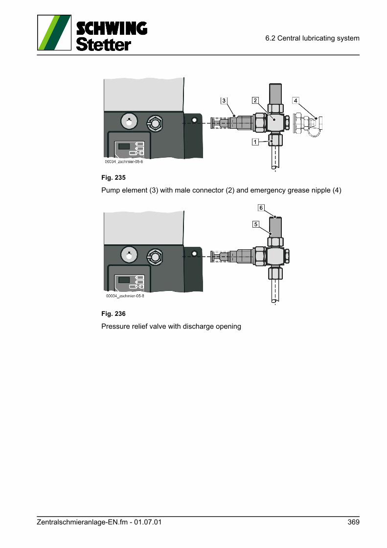
6.2 Central lubricating system
Fig. 235
Pump element (3) with male connector (2) and emergency grease nipple (4)
Fig. 236
Pressure relief valve with discharge opening
Zentralschmieranlage-EN.fm - 01.07.01 369

6.2 Central lubricating system
6.2.3 Configuring the system
The pump units of the KFGS series are equipped with integrated control part type IG502-2-I with an operating display (Fig. 237). Operating parameters such as pause times (Timer) and pump runtimes (Contact) can be parameterised via the control part.
The display and operating unit is protected from spray water and mechanical dam-age by a transparent plastic cover. For programming, the cover must be removed and then reinstalled.
Fig. 237 Operating display
As lubrication of the lubrication points is only necessary at given intervals, the lu-brication cycle or lubrication procedure is divided into a pump runtime and a pause time. A lubrication cycle always begins with a pump runtime.
Display elements and controls on the KFGS operating display (Fig. 237)
Depiction Designation Function of
Three-digit LED display Values and operating status
PAUSE LED Pause time
CONTACT LED Contact time display (pumping operation)
1 = CS LED2 = PS LED
CS=Cycle Switch: monitors the function with an external cycle switchPS=Pressure Switch:monitors the function with an external pressure switch
FAULT LED Fault message
UP or DOWN buttonSwitch on displayDisplay values and parametersSet values and parameters
SET buttonSwitch between programming and display modeConfirm values
DK buttonTrigger in-between lubricationErase fault message
370 Zentralschmieranlage-EN.fm - 01.07.01
6.2 Central lubricating system
After the pump runtime, the lubrication cycle is interrupted and then resumed after the configured pause time.
That is, a lubrication cycle always starts with the "residual lubrication time" or "re-sidual pause time".
Even a power failure cannot erase the integrated data memory.
6.2.3.1 Pump runtime
The pump runtime corresponds to the time in which the pump conveys the lubri-cant.
In the case of a division into lubrication segments, one of the segment valves will be opened at the same time and closed again at the end of the pump runtime.
The duration of the pump runtime can be configured as a time value in hours, min-utes and seconds.
6.2.3.2 Pause time
In the pause time, also referred to just as pause, the pump rests or in the case of a division into lubrication segments, the valve for the affected lubrication segment is closed.
The duration of the pause time can be configured.
In automatic operating mode, the pause time is determined by specifying a time val-ue (Pause timer).
When configuring the lubrication scenario, the pause time thus corresponds to a delay time, by which the valves of the individual lubrication segments are opened successively once a lubrication cycle has been started. This therefore prevents all valves from opening at the same time.
Zentralschmieranlage-EN.fm - 01.07.01 371
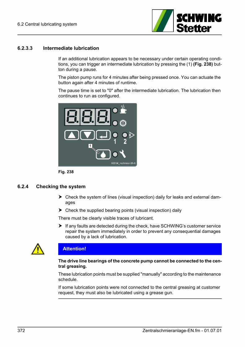
6.2 Central lubricating system
6.2.3.3 Intermediate lubrication
If an additional lubrication appears to be necessary under certain operating condi-tions, you can trigger an intermediate lubrication by pressing the (1) (Fig. 238) but-ton during a pause.
The piston pump runs for 4 minutes after being pressed once. You can actuate the button again after 4 minutes of runtime.
The pause time is set to "0" after the intermediate lubrication. The lubrication then continues to run as configured.
Fig. 238
6.2.4 Checking the system
Check the system of lines (visual inspection) daily for leaks and external dam-ages
Check the supplied bearing points (visual inspection) daily
There must be clearly visible traces of lubricant.
If any faults are detected during the check, have SCHWING’s customer service repair the system immediately in order to prevent any consequential damages caused by a lack of lubrication.
ACHTUNG! Attention!
The drive line bearings of the concrete pump cannot be connected to the cen-tral greasing.
These lubrication points must be supplied "manually" according to the maintenance schedule.
If some lubrication points were not connected to the central greasing at customer request, they must also be lubricated using a grease gun.
372 Zentralschmieranlage-EN.fm - 01.07.01
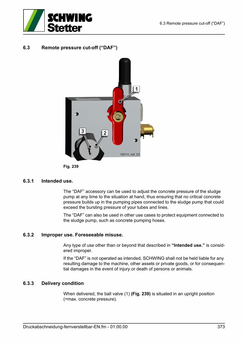
6.3 Remote pressure cut-off (“DAF”)
6.3 Remote pressure cut-off (“DAF”)
Fig. 239
6.3.1 Intended use.
The “DAF” accessory can be used to adjust the concrete pressure of the sludge pump at any time to the situation at hand, thus ensuring that no critical concrete pressure builds up in the pumping pipes connected to the sludge pump that could exceed the bursting pressure of your tubes and lines.
The “DAF” can also be used in other use cases to protect equipment connected to the sludge pump, such as concrete pumping hoses.
6.3.2 Improper use. Foreseeable misuse.
Any type of use other than or beyond that described in “Intended use.” is consid-ered improper.
If the “DAF” is not operated as intended, SCHWING shall not be held liable for any resulting damage to the machine, other assets or private goods, or for consequen-tial damages in the event of injury or death of persons or animals.
6.3.3 Delivery condition
When delivered, the ball valve (1) (Fig. 239) is situated in an upright position (=max. concrete pressure).
Druckabschneidung-fernverstellbar-EN.fm - 01.00.00 373
6.3 Remote pressure cut-off (“DAF”)
The hand-wheel (2) (Fig. 242) is locked and the key is located on the right-hand side inside the control cabinet.
Always store the key in a secure location in order to prevent unauthorised adjust-ments.
6.3.4 Step-by-step instructions
Proceed as follows in order to use the “DAF”.
Situation:
You have acquainted yourself with the prevailing conditions on the jobsite before-hand and need to configure the “DAF” accordingly.
Adjust the pressure of your concrete pump in accordance with the requirements:
1. First proceed as described for the pressure control (in the “Pressure control” chapter of your operating instructions).
2. Move both ball valves (1+2) (Fig. 240) on the pump kit into the “pressure con-trol” position (Fig. 241) so that the pistons come to a standstill.
ACHTUNG! Attention!
Material damage may be caused by switching during pumping operations!
Only change the position of the ball valve (1) (Fig. 242) if your concrete pump is set to the minimum delivery rate!
3. Move the ball valve (1) (Fig. 242) into the “I variable concrete pressure” position.
4. Start the concrete pump as per usual.
5. Now observe the pressure gauge on your “DAF” (4) (Fig. 242).
6. Unlock the hand-wheel using the key (3) (Fig. 242).
7. If the hydraulic pressure on the “DAF’s” pressure gauge remains constant, the reduced hydraulic pressure that was last configured has been reached.
8. Now set the new maximum pressure using the hand-wheel (2) (Fig. 239).
a) To do this, please refer to the sign on the “DAF” block containing the required conversion factor for the respective pump (e.g., P2023-110/75 RB). [Pconcrete = Phydraulic x 0.25]
b) In the example, the value displayed on the “DAF’s” pressure gauge has to be multiplied by 0.25 in order to obtain the desired concrete pressure.
3. After configuring the pressure, lock the hand-wheel again using the key / (se-cure it against being changed without authorisation) and remove the key.
4. Move the ball valves on the pump kit of your truck-mounted concrete pump back to the “operating position”. To do this, carefully follow the descriptions in the “Pressure control” chapter of your operating instructions.
374 Druckabschneidung-fernverstellbar-EN.fm - 01.00.00
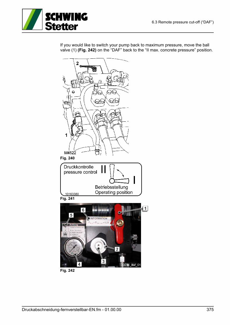
6.3 Remote pressure cut-off (“DAF”)
If you would like to switch your pump back to maximum pressure, move the ball valve (1) (Fig. 242) on the “DAF” back to the “II max. concrete pressure” position.
Fig. 240
Fig. 241
Fig. 242
Druckabschneidung-fernverstellbar-EN.fm - 01.00.00 375

6.3 Remote pressure cut-off (“DAF”)
376 Druckabschneidung-fernverstellbar-EN.fm - 01.00.00

Trennblatt_Kapitel-Anhang-EN
7 Appendix
.fm 377

7 Appendix
378 Trennblatt_Kapitel-Anhang-EN.fm -
7.1 Information service
7.1 Information service
Are you already using our information service? - 5 minutes that pay off!
Dear Customer,
With the purchase of your SCHWING machine, you have acquired a high quality product.
Of course, we are constantly working to improve our products and would like to in-form you when new findings become available. This service is completely free of charge, because we highly value customer support and product monitoring!
Our offer also expressly applies when the SCHWING machine was obtained sec-ond-hand!
In order to send you our information, we need your address.
Please complete the following questionnaire and send it to
SCHWING GmbH
Service
PO Box 20 03 62
D-44647 Herne
Of course you can also fax us this page or reply by email:
Fax: +49 (0)2325 74674 Email: [email protected]
We look forward to your response!
Infodienst-EN.fm - 01.00.01 379
7.1 Information service
Please complete in block letters:
Customer no.:
Address:
Country:
Contact person:
Telephone:
Fax:
Email:
Machine type:
Machine no.:
380 Infodienst-EN.fm - 01.00.00

7.2 Always nearby
7.2 Always nearby
HERNE
SCHWING GmbH
Service Centre
Heerstraße 9-27
44653 Herne
Telephone: 02325/9870
ET Sales:
02325/987-352
Customer Service:
02325/987-231/232
Fax; 02325/987-470
Email: [email protected]
Contact: Mr Beiersdorf
HAMBURG BERLIN
SCHWING Stetter SCHWING Stetter
Service Branch
Gewerbegebiet Ost
Theodor-Storm-Straße 9
25451 Quickborn/Holstein
Service Support Centre
Gewerbegebiet Neu Boston
Kurzer Weg 7
15859 Storkow
Telephone: 04106/72321
Fax; 04106/71810
Telephone: 033678/61308
033678/62015
Fax; 033678/62015
Email: [email protected]
Contact: Mr Hermann
Email: [email protected]
Contact: Mr Rahming
KASSEL GOTHA
SCHWING Stetter
Service BranchEberhard Becker & Partner GmbH
Crumbacher Straße 56
34277 Fuldabrück
Dr.-Troch-Straße 15
99867 Gotha
Telephone: 0561/581561
Fax; 0561/582963
Telephone: 03621/404444
03621/404445
Fax; 03621/404446
Email: [email protected]
Contact: Mr Döring
Email: [email protected]
Contact: Mr Becker
Immer-in-ihrer-Naehe-EN.fm - 01.01.01 381
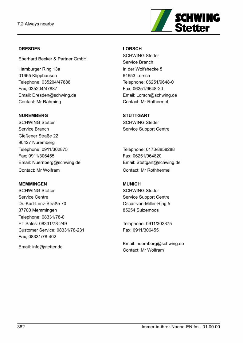
7.2 Always nearby
DRESDEN LORSCH
Eberhard Becker & Partner GmbHSCHWING Stetter
Service Branch
Hamburger Ring 13a
01665 Klipphausen
Telephone: 035204/47888
Fax; 035204/47887
Email: [email protected]
Contact: Mr Rahming
In der Wolfshecke 5
64653 Lorsch
Telephone: 06251/9648-0
Fax; 06251/9648-20
Email: [email protected]
Contact: Mr Rothermel
NUREMBERG STUTTGART
SCHWING Stetter
Service Branch
SCHWING Stetter
Service Support Centre
Gießener Straße 22
90427 Nuremberg
Telephone: 0911/302875
Fax; 0911/306455
Email: [email protected]
Contact: Mr Wolfram
Telephone: 0173/8858288
Fax; 06251/964820
Email: [email protected]
Contact: Mr Rothhermel
MEMMINGEN
SCHWING Stetter
Service Centre
Dr.-Karl-Lenz-Straße 70
87700 Memmingen
MUNICH
SCHWING Stetter
Service Support Centre
Oscar-von-Miller-Ring 5
85254 Sulzemoos
Telephone: 08331/78-0
ET Sales: 08331/78-249
Customer Service: 08331/78-231
Fax; 08331/78-402
Telephone: 0911/302875
Fax; 0911/306455
Email: [email protected]: [email protected]
Contact: Mr Wolfram
382 Immer-in-ihrer-Naehe-EN.fm - 01.00.00

7.3 Always Ready
7.3 Always Ready
Germany
Schwing/Stetter GmbH
Heerstr. 9 ‐ 27
D ‐ 44653 Herne
0049 ‐ 2325 ‐ 987 0
0049 ‐ 2325 ‐ 72922
Germany
Schwing Hydraulik‐Elektronik
GmbH
Dorstener Str. 428
D ‐ 44653 Herne
0049 ‐ 2325 ‐ 987 0
0049 ‐ 2325 ‐ 50568
Germany
Stetter GmbH
Dr. Karl‐Lenz‐Str. 70
D ‐ 87700 Memmingen
0049 ‐ 8331 ‐ 78 0
0049 ‐ 8331 ‐ 78
275
Egypt
Memo Industrial Planning Ltd.
El Nozha Street Nasr City
P. O. Box 4525
11717 Cairo
0020 ‐ 2 ‐ 2419
2989
0020 ‐ 2 ‐ 2419
2986
memo@memoindustr
ial.com
People's Democratic
Republic of Algeria
Schwing/Stetter
Cité des PTT
Rue C N° 55A
Vallée de MAZA ‐ Hydra
00213 ‐ 21 ‐ 60 82
63
00213 ‐ 21 ‐ 60 55
66
Republic of Angola
Cimertex S. A.
Rua do Abade Mondego, 165
4455 ‐ 489 Perafita
Matosinhos
00351 ‐ 220 ‐ 912
600
00351 ‐ 220 ‐ 912
665
Republic of Argentina
Repas S/A
Reconquista 336
piso 12 OF. "Y"
1335 Buenos Aires
0054 ‐ 1 ‐ 14393
9243
0054 ‐ 1 ‐ 14394
4965
m.ar
Republic of Argentina
Repas S/A
Ruta Panamericana Col.
Oeste
Km 28,900
1611 Don Torcuato
Pcia. Buenos Aires
0054 ‐ 1 ‐ 14846‐
1073
0054 ‐ 1 ‐ 14748‐
4263
m.ar
Always-Ready-EN.fm - 01.01.01 383

7.3 Always Ready
Australia
Schwing Australia Pty. Ltd.
77 Avoca Drive
Green Point
NSW 2251
0061 ‐ 2 ‐ 4369
6884
0061 ‐ 2 ‐ 4369
6774
m.au
Mamlakat al‐Bahrain
Nass Commercial
Commercial Division
P.O. Box 669
Manama
00973 ‐ 17 703 123
00973 ‐ 17703090
info@nasscommercial
.com
www.nassgroup.com
384 Always-Ready-EN.fm - 01.01.01

7.3 Always Ready
Kingdom of Belgium
MRC Betontechniek
Oost Jachtpark 14
9100 Sint Niklaas
0032 ‐ 3766 7666
0032 ‐ 3766 2958
reginald.judy@skynet.
be
Kingdom of Belgium
n.v. auto‐ Construct
Reutelhoekstraat 1 a
8980 Zonnebeke
0032 ‐ 57466939
0032 ‐ 57466231
Federal Republic of Brazil
Schwing Equipamentos Ind.
Ltda.
Rod. Fernão Dias, Km 56
Bairro terra Preta
07600‐000 Mairiporá ‐ S.P.
0055 ‐ 11 ‐ 4486
8500
0055 ‐ 11 ‐ 4486
1344
info@schwing‐
stetter.com.br
Republic of Bulgaria
Wassilev BM Eood
Br. Bakston‐Str. 134
4004 Plovdiv
00359 ‐ 32 ‐ 692727
00359 ‐ 32 ‐ 698
675
g
Republic of Chile
Emaresa Ingenieros y
Representaciones S.A.
Santa Adela
9901 Maipu
Santiago do Chile
0056 ‐ 2 ‐ 4602020
0056 ‐ 2 ‐ 460 2025
evbischho@emaresa.
cl
Republic of Costa Rica
Imocom De Costa Rica, S.A.
De Ucimed ‐ Los Anonos
500 metros oeste
Entrada Barrio Holanda
100 metros, mana derecha
casa No. 14
San Jose 1000
00506 ‐ 291‐5212
o. 5213
00506 ‐ 291‐5214
imocomcostarica@ice
.co.cr
Kingdom of Denmark
Bekoteknik
Vaerkstedsvej 23
4600 Koge
0045 ‐ 56 ‐ 636 633
0045 ‐ 56 ‐ 636 368
Kingdom of Denmark
ABS Pumper A/S
Gydevang 30
DK 3450 Allerod
0045 ‐ 48 ‐ 17 11 10
0045 ‐ 48 ‐ 17 19 11
abspumper@abspum
per.dk
Republic of Ecuador
Imocom Ecuatoriana Cia. Ltd.
Corea 318 y Nunez de Vela
Edifico Karolina 2000 Planta
baja
Quito
00593 ‐ 2 ‐ 2435‐
678
00593 ‐ 2 ‐ 2447
664
m
Always-Ready-EN.fm - 01.01.01 385

7.3 Always Ready
Republic of Ecuador
Imocom Ecuatoriana Cia.
Ltda.
Av. Francisco de Orellana
2001
Edf. AS‐1, Cdla letel Detras
dicentro Guayaquil
Guayaquil
00593 ‐ 4 ‐ 423‐
2470
00593 ‐ 4 ‐ 423‐
1595
.net
Republic of the Ivory Coast
CFCI Technique
6, Rue Thomas Edison Zone 4
B.P. 1844 Abidjan
Elfenbeinküste
00225 ‐ 354 034
Republic of Finland
Mytec Oy
Rahkontie 21
85140 TYNKÄ
Finland
00358 ‐ 207528240
00358 ‐ 207528249
mikko.ylitalo@mytec.
fi
Republic of Finland
Tamflow OY
Kalevanpuistotie 7
33500 Tampere
Finland
00358 ‐ 3 ‐ 31 38 44
00
00358 ‐ 3 ‐ 31 38 44
44
i
Republic of France
Schwing / Stetter S.A.
12, Rue des Tuileries
B.P.44
67460 Souffelweyersheim
0033 ‐ 3 ‐ 8881
5151
0033 ‐ 3 ‐ 8833
9955
DI@schwing‐
stetter.fr
Republic of France
Impasse du Vexin
78250 Hardricourt
France
0033‐1 ‐ 3492 9505
0033‐1 ‐ 3474 7260
Federal Republic of Greece
Schwing/Stetter Hellas S. A.
G. Margaritis ‐ G. Karvounis
Leoforos Athinon 204
GR‐10442 Athens
0030 ‐ 210 ‐ 5155
505
0030 ‐ 210 ‐ 5150
034
United Kingdom of Great
Britain
Schwing/Stetter (UK) Ltd
Unit 11, Perivale Ind. Estate
Horsenden Lane South
Greenford
Middlesex UB6 7RL
0044 ‐ 20 ‐ 8997
1515
0044 ‐ 20 ‐ 8998
3517
hughbyrne@burlingt
on‐
engineers.co.uk
386 Always-Ready-EN.fm - 01.01.01

7.3 Always Ready
Republic of Guatemala
Imocom Centroamericana S/
A de CA
8a, Calle 3‐142, Zona 10
Apartado Postal 639 A
Guatemala City
00502 ‐ 2 ‐ 334
6148
00502 ‐ 2 ‐ 360
9677
m.gt
Always-Ready-EN.fm - 01.01.01 387

7.3 Always Ready
Hong Kong
Ekpac Equipment Limited
255 Gloucester Road
2803 Sino Plaza Causeway
Bay
Hong Kong
00852 ‐ 2555 5555
00852 ‐ 2873 6230
www.ekpac.com
Hong Kong
C. Crossfield & Co. Ltd.
Room 1102 ‐ 1112
Corporation Square
8 Lam Lok Street
Kowloon Bay/Kowloon
00852 ‐ 2753 8500
00852 ‐ 2756 0700
om.hk
Republic of India
Schwing/Stetter (India) PVT.
Ltd.
F‐71 + 72, SIPCOT Industrial
Park
Irungattukottai
Sriperumpudur Taluk
Kancheepuram District
Tamil Nadu 602 105
0091 ‐ 44 ‐ 371 78
100
0091 ‐ 44 ‐ 271 56
539
info@schwingstetterin
dia.com
Republic of India
Schwing/Stetter (India) PVT.
Ltd.
620 / 621, Nirmal Lifestyle
Corporate Centre
6th Floor, LBS Marg
Mulund ‐ ( WEST )
Mumbai ‐ 400 080
0091 ‐ 22 ‐ 256
24862
‐ /863
0091 ‐ 22 ‐ 256
24865 / 6
$SSIPL‐
e
Republic of India
Schwing/Stetter (India) PVT.
Ltd.
19, Okhla Industrial Estate
Phase III
New Delhi 110 020
0091 ‐ 11 ‐ 4290
3000
0091 ‐ 11 ‐ 4290
3030
SSIPL‐
Newdelhi@schwingste
tterindia.com
Republic of Indonesia
PT. Cahaya Indotama
Engineering
JALAN JABABEKA 5 BLOK F
NO. 4
CIKARANG, BEKASI 17550
0062 ‐ 21 ‐ 8983
3124
& 8983 3125
0062 ‐ 21‐ 8981
1537
m
388 Always-Ready-EN.fm - 01.01.01

7.3 Always Ready
Republic of Iran
Schwing Stetter Pars
Hamgam
Hydraulic Robat Co.
No. 97 Karoon Ave next to
Tolid St Emam Khomeyni
Blvd
Robat Karim Saveh Road
Tehran
+49 172 ‐ 150‐4648 szaidi@schwingstetterpa
rs.de
Ireland
Harris Assemblers
Naas Road
P. O. Box 3960
Dublin 12
00353 ‐ 1 ‐ 4194
500
00353 ‐ 1 ‐ 4602
278
Always-Ready-EN.fm - 01.01.01 389

7.3 Always Ready
Republic of Iceland
Thor Ltd.
P.O. Box 1194
Reykjavik
00354 ‐ 681 500
Israel
M. Bar Maintenance Ltd.
P.O. Box 3055
20 Harduf Hanechalim Street
38900 Caesarea
00972 ‐ 4 ‐ 6378595
00972 ‐ 4 ‐ 6378667
al‐Mamlaka al‐Urduniyya al‐
Ha‐schimiyya
Farradj & Co.
P. O. Box 974
Jabal El Weibdeh
Amman 11118
Jordan
00962 ‐ 6 ‐ 464
3800 o. 3801 o.
2900
00962 ‐ 6 ‐ 464
3901
k.abujaber@
abujaber‐group.com
Republic of Colombia
Gecolsa
Avd. Amèricas No. 42A ‐ 21
Bogotá
0057 ‐ 1 ‐ 405 5554
or 405 5544
0057 ‐ 1 ‐ 268 4902
cesar_palomino@geco
lsa.
com.co
Daehan Minguk
ENC., Ltd.
4 floor, yuhan (old) B/D
# 49‐6 Daebang‐Dong,
Dongjak‐Gu
Seoul
0082 ‐ 2 ‐ 8282 ‐
119
0082 ‐ 2 ‐ 8282 ‐
125
Republic of Croatia
Zupanac/Stepinac GmbH
Domoviceva 4
10255 Gornji Stupnik
Zagreb
003851 ‐ 6588 568
003851 ‐ 6588 568
net.hr
Daulat al‐Kuwait
Equipment Company
P.O. Box 192
99, Shuwaikh Industrial Area
Block No. 2, Street No. 12
13002 Kuwait/Safat
00965 ‐ 1802440 [email protected]
om
www.equipcokuwait.c
om
Daulat al‐Kuwait
Al‐Khonaini al‐Katami
Trading & Contracting Co.
P.O. Box 593
Safat
Kuwait
00965 ‐ 483 1955
00965 ‐ 484 2986
Lebanon
Baladi Freres S.A.L.
P.O. Box 90‐1191
Jdeidet El Metn
Metn 1202 2090
00961 ‐ 1 ‐ 873 992
o. 894 841
00961 ‐ 1 ‐ 884 010
m
390 Always-Ready-EN.fm - 01.01.01

7.3 Always Ready
Libya
Mediterranean Engineering
& Maintenance Operation
Erabi Compound, Office No.
60
P.O. Box 83993
Tripoli
00218 ‐ 92501 3310
00218 ‐ 21 ‐ 480
6473
et
Always-Ready-EN.fm - 01.01.01 391

7.3 Always Ready
Grand Duchy of Luxembourg
Comat S.A.
Zone Industrielle
10, Rue de bruyeres
1274 Howald
00352 ‐ 496 121
00352 ‐ 402 274
Malaysia
UMW Equipment Sdn Bhd
Jalan Utas 15/7
P.O. Box 7052
40915 Shah Alam, Sengalor
Darul Ehsan
0060 ‐ 3 ‐ 5519
1911
0060 ‐ 3 ‐ 5510
5517
Morocco
Game Maroc
148‐150, Bd. Emile‐Zola
MA‐21700 Casablanca
00212 ‐ 2 ‐ 248 660
00212 ‐ 2 ‐ 245 442
United Mexican States
Imocom de Mexico S/A de CV
Av. Presidente Juárez No.
2032
Col. La Loma
Tlalnepantla, Edo. de
Mexico
54000 México
0052 ‐ 55 ‐ 9114 ‐
3918
0052 ‐ 55 ‐ 9114 ‐
3930
m.mx
United Mexican States
Imocom de Mexico S/A de CA
Av. Afonso Reyes 1760
Fracc. Bernado Reyes
Monterrey, N.L.
0052 ‐ 8 ‐ 311 0411
0052 ‐ 8 ‐ 311 0911
The Netherlands
Schwing/Stetter B.V.
Bliek 15 (Dombusch 1)
NL‐4941 SG
Raamsdonksveer
0031 ‐ 162 ‐ 518
882
0031 ‐ 162 ‐ 518
699
The Netherlands
Axflow B.V.
De Steiger 30
NL‐1351 AB Almere
0031 ‐ 365 ‐ 381
211
0031 ‐ 365 ‐ 314
004
Federal Republic of Nigeria
B M E Baumaschinen &
Ersatzteilhandels GmbH
Flischstraße 53
60388 Frankfurt
0 69 ‐ 4 20 97 30
0 69 ‐ 4 20 37 60
Kingdom of Norway
Alpha Maskin AS
PO Box 56
N ‐ 1901 Fetsund
0047 ‐ 63 ‐ 88 78 70
0047 ‐ 63 ‐ 88 78 71
o
392 Always-Ready-EN.fm - 01.01.01

7.3 Always Ready
Kingdom of Norway
ABS Pumper A/S
PO Box 473
Sandvika
0047 ‐ 6 ‐ 754 4760
0047 ‐ 6 ‐ 754 3848
Sultanate of Oman
AL Fairuz Trading & Cont. Co.
Wadi Adal ‐ Al Amerat Road
P.O. Box 330, Muscat
Postal Code ‐ 100
00968 ‐ 2456 1399 [email protected]
m
www.alfairuzoman.co
m
Always-Ready-EN.fm - 01.01.01 393

7.3 Always Ready
Federal Republic of Austria
Schwing/Stetter
Baumachinen Ges.m.b.H
Heizwerkstraße 6
1230 Vienna
0043 ‐ 16 16 73 13
0043 ‐ 16 16 70 66
Federal Republic of Austria
Schwing GmbH
Friedrich‐Wilh. Schwing Str. 1
9431 St. Stefan Lavanttal
0043 ‐ 43 52 28 12
0043 ‐ 43 52 29 53
Republic of Peru
Gordon Ingenieros
Maquinaria S.A.
A. Franco 282 Urb. Chama
Lima 33
0051 ‐ 1‐ 448 6612
0051 ‐ 1 ‐ 448 3725
.net.pe
Republic of Poland
Republic of Portugal
Edificio Vecofabril
Divisao Equibetão
Estrada da Paiã
1679‐007 Pontinha
+351 (21) 478 8500 pedro.f.maia@equibetao
.pt
Commonwealth of Puerto
Rico
Hill Construccion
Montehiedra Cinema Bldg.
Suite 201 (Altos Banco Bilboa
Vicaya)
Montehiedra Town Center
9410 Los Romeros, AV San
Juan
001 ‐ 787 ‐287 3200
001 ‐ 787 ‐ 287
3204
State of Qatar
Quatar Tractor & Equipment
Co.
P.O. Box 5257
Doha
00974 ‐ 44602946 [email protected]
a
www.talebgroup.com
Romania
Kreis Construct
7, I.C. Bratianu Str.
Otopeni
075100 ILFOV
0040 ‐ 21 ‐ 350 20
56 o.57 o. 58
0040 ‐ 21 ‐ 350 20
53 o. 55
Federation of Russia
Puschkiner
Baumaschinenwerk
Puschkiner Kreis
Ul.Novoderevenskaya 17
196 608 St. Petersburg
007 ‐ 812 ‐ 476
2411
007 ‐ 812 ‐ 470
1951
394 Always-Ready-EN.fm - 01.01.01

7.3 Always Ready
Federation of Russia
Schwing/Stetter
Krasnopresnenskaja
Naberezhnaja 12
Entry 6 ‐ Apartment 1412
123610 Moscow
007 ‐ 495 ‐ 258
1412
007 ‐ 495 ‐ 258
2092
Stetter@datarecovery.
ru
Saudi Arabia
Zahid Tractor Co.
P.O. Box 1588
Jeddah 12441
00966 ‐ (0) 2
6209173
Saudi Arabia
Bakheet Co. for Machinery
P.O. Box 6101
Madina Road, Kilo 9
Jeddah 21442
00966 ‐ (0) 2 691
0550
m.sa
www.bakheet.com.sa
Kingdom of Sweden
Bekoteknik Sverige AB
Möbelgatan 4
43133 Mölndal
0046 ‐ 31 ‐ 30 11
241
0046 ‐ 31 ‐ 30 11
248
Kingdom of Sweden
MAF Sweden AB
E.A. Rosengrem gata 27
S‐42131 V. Frölunda
0046 ‐ 31 ‐ 45 27 40
0046 ‐ 31 ‐ 49 76 81
Swiss Confederation
Avesco AG
Hasenmatt Str. 2
CH‐4901 Langenthal
0041 ‐ 62 ‐ 915 80
80
0041 ‐ 62 ‐ 915 81
35
Lukas.Schreiber@aves
co.ch
Swiss Confederation
Ingtec AG
PO Box 2 16
Unterfortstraße
CH‐4313 Möhlin
0041 ‐ 61 ‐ 8 55 51
51
0041 ‐ 61 ‐ 8 55 30
31
Republic of Serbia
Magni‐Baza d.o.o.
Ustanicka 128 A, V sprat
11000 Belgrade
Serbia
0038 ‐ 11 ‐
13474183
0038 ‐ 11 ‐
13474182
Robert.mecava@magn
ibaza.com
Republic of Singapore
UMW Equipment & Engineering Pte
Ltd.
108 International Road
Singapore 629 173
0065 ‐ 6265 3155
0065 ‐ 6265 8494
richard.ho.kt@umwee
pl.com.sg
Always-Ready-EN.fm - 01.01.01 395

7.3 Always Ready
Kingdom of Spain
Schwing/Stetter Iberica S. L.
C.I.F.: B‐84832997
C/Nardos, n° 15, Polígono
Industrial El Molino
28970 Humanes de Madrid
0034 ‐ 91 ‐ 6162
700
0034 ‐ 91 ‐ 6162
753
cgrohmann@schwing.
es
396 Always-Ready-EN.fm - 01.01.01

7.3 Always Ready
Republic of South Africa
TFM Industries
411 Industry Road
Clayville Ext 4
P.O. Box 1200
Olifantsfontein
0027 ‐ 11 ‐ 316
4161
0027 ‐ 11 ‐ 316
4786
Syria
Said Kourabi & Co.
P.O. Box 2966
63, Jadet Hafez Ibrahim Al
Shalan Str.
Damascus
00963 ‐ 11 ‐ 333 65
62
00963 ‐ 11 ‐ 333 79
93
Taiwan
Shenger Corporation
G 21 Fl.
No. 98, Hsin‐Tai‐Wu Rd.
Section 1, Hsi‐Chih
Taipei Hsien
00886 ‐ 2 ‐ 770
88168
00886 ‐ 2 ‐ 770
88198
.tw
Kingdom of Thailand
C & C Corporation Ltd.
495 Krungthep Kreetha Road
Huamark. Bangapi
Bangkok 10240
0066 ‐ 2 ‐ 7317364 ‐
73
0066 ‐ 2 ‐ 7316824
Czech Republic
Schwing/Stetter Ostrava
s.r.o.
Moravska 1215/6
CZ‐70030 Ostrava‐Hrabuvka
00420 ‐ 596 ‐ 746
780 ‐ 2
00420 ‐ 596 ‐ 746
783
Republic of Turkey
Alfatek Co. Ltd
Ferhatpasa Mah., Akdeniz
CAD. G‐63 SK., No 4
34888 Samandira ‐ Istanbul
0090 ‐ 216 ‐ 660 09
00
0090 ‐ 216 ‐ 660 09
09
c.simsek@alfatekturk.
com
Ukraine
Construction Machinery Ltd.
54 a, Petropavlovskaya Str.
04086 Kiev
00380 ‐ 44 ‐ 467
2601 o. 467 2602
00380 ‐ 44 ‐ 467
2607
m.ua
United States of America
Schwing America, Inc.
5900 Centerville Road
White Bear
Minnesota 55127
001 ‐ 651 ‐ 4 29 09
99
001 ‐ 651 ‐ 4 29 34
64
Always-Ready-EN.fm - 01.01.01 397

7.3 Always Ready
Bolivarian Republic of
Venezuela
Inversiones Resansil, CA
4a. Tranv. De Montecristo,
Edif.
Bancaracas, Piso 2, Oficina 2,
Caracas 1071
0058 ‐ 2 ‐ 12237
7726
0058 ‐ 2 ‐ 12237
9515
U.A.E.
Schwing GmbH‐Dubai Branch
Dubai Investment Park
European Business Centre
3rd Floor, Office #326
P.O. Box 487432
Jebel Ali
00971 ‐ 4 ‐ 88 55
145
00971 ‐ 50 ‐ 298
3203
00971 ‐ 4 ‐ 88 55
146
H. Shukoor
398 Always-Ready-EN.fm - 01.01.01

7.3 Always Ready
U.A.E.
Construction Machinery
Center Co.
P.O. Box 5261
Deira
Dubai
00971 ‐ 4 ‐ 2858959 [email protected]
www.cmcgulf.com
U.A.E.
Inma ‐ The Gulf Development
& Construction Co.
P.O. Box 4560
Dubai
0097 ‐ 14 ‐ 2857
272
0097 ‐ 14 ‐ 2857
512
Vietnam
GREEN INDOCHINA
INVESTMENT &
COMMERCIAL CORP.
No. 14 lot 10B, Trung yen
New Residential Area
Trung Hoa, Cau giay
Hanoi
0084 ‐ 4 ‐ 3783
4234
0084 ‐ 4 ‐ 3783
4256
vn
Republic of China
Schwing Shanghai Machinery
Co.Ltd.
5 Xin Xiao Road
Xin Qiao Industrial Zone
Song Jiang
Shanghai 201 602
0086 ‐ 21 ‐ 5764
5855
0086 ‐ 21 ‐ 5764
5577
Yemen
Mugahed Trading Company
LTD.
P. O. Box 837
Sana'a
Republic of Yemen
00967 ‐ 1447 961‐2
00967 ‐ 1447 963
Cyprus
Uniplant Ltd.
P.O. Box 12516
182, Limassol Avenue
CY‐ 2250 Latsia
00357 ‐ 2 ‐ 488777
00357 ‐ 2 ‐ 488885
Always-Ready-EN.fm - 01.01.01 399

7.3 Always Ready
400 Always-Ready-EN.fm - 01.01.01
7.4 VDMA safety manual
7.4 VDMA safety manual
This chapter serves as the safety manual and contains basic safety instructions re-garding the operation of pumping, spraying and spreading machinery for concrete.
The safety manual is prepared jointly by leading manufacturers of concrete pump-ing and spreading machines under the auspices of the VDMA (Verband Deutscher Maschinen- und Anlagenbau/Mechanical Engineering Industry Association). It is applicable to our machines in full.
For this reason, the safety manual has a chapter of its own and separate page num-bers.
Specific warnings can always be found before each description of a dangerous ac-tivity.
Vorwort-Sicherheitshandbuch-VDMA-EN.fm - 01.00.01 401

7.4 VDMA safety manual
402 Vorwort-Sicherheitshandbuch-VDMA-EN.fm - 01.00.01

Safety ManualConcrete delivery and placing machines
01/2018 Rev16 EN
Imprint
Edition 01/2018 Rev16 EN
Published by:
Verband Deutscher Maschinen- und Anlagenbau e. V. (VDMA)Bau- und BaustoffmaschinenLyoner Straße 1860528 Frankfurt
Telefon +49 69 6603-1262Fax +49 69 6603-2262E-Mail [email protected] bub.vdma.org
This safety manual was produced withthe co–operation of the following com‐panies:
Putzmeister Concrete Pumps GmbH Max–Eyth–Straße 10 72631 Aichtal
Schwing GmbH Heerstraße 9–27 44653 Herne
Liebherr–Betonpumpen GmbH Lessingstraße 4 89231 Neu–Ulm
Table of contents
Foreword ................................................................................. 7
1 Terms, definitions, requirements ............................................ 91.1 Definition of terms ........................................................................................................... 111.1.1 Machine ........................................................................................................................... 111.1.2 Concrete pump ................................................................................................................ 111.1.3 Arm assembly ................................................................................................................. 111.1.4 Placing boom .................................................................................................................. 111.1.5 Base structure ................................................................................................................. 111.1.6 Truck mixer ..................................................................................................................... 121.1.7 Delivery line systems ...................................................................................................... 121.1.8 End hose ......................................................................................................................... 121.1.9 Manufacturer ................................................................................................................... 121.1.10 Operator .......................................................................................................................... 121.1.11 Machine operator ............................................................................................................ 121.1.12 Hoseman ......................................................................................................................... 121.1.13 Signaller and other auxiliary personnel ........................................................................... 131.1.14 Truck mixer driver ........................................................................................................... 131.1.15 Subject expert ................................................................................................................. 131.1.16 Qualified personnel ......................................................................................................... 131.1.17 After Sales Service personnel ......................................................................................... 131.1.18 Maintenance .................................................................................................................... 131.1.19 Place of work, working area, danger zone ...................................................................... 14
1.2 Designated use ............................................................................................................... 181.2.1 Retesting (safety inspection) ........................................................................................... 191.2.2 Inspection intervals for retesting ..................................................................................... 19
1.3 Improper use ................................................................................................................... 201.3.1 Transporting goods ......................................................................................................... 201.3.2 Lifting loads ..................................................................................................................... 211.3.3 Removing obstacles ........................................................................................................ 211.3.4 Extending the reach ........................................................................................................ 211.3.5 Extending the placing boom and end hose ..................................................................... 211.3.6 Impermissible end hose .................................................................................................. 221.3.7 Impermissible working area ............................................................................................ 221.3.8 Climbing the placing boom .............................................................................................. 231.3.9 Highpressure delivery ..................................................................................................... 231.3.10 Accessories and attachments ......................................................................................... 231.3.11 Changes to the machine ................................................................................................. 23
1.4 Exclusion of liability ......................................................................................................... 24
Table of contentsConcrete delivery and placing machines
1.2.3.. . .
01/2018 Rev16 EN 3
1.5 Personnel ........................................................................................................................ 241.5.1 Requirements .................................................................................................................. 241.5.2 Qualifications ................................................................................................................... 251.5.3 Responsibility of the machine operator ........................................................................... 25
1.6 Operating Instructions, operating procedures and other regulations .............................. 251.6.1 Operating Instructions ..................................................................................................... 251.6.2 Operating procedures ..................................................................................................... 261.6.3 Other regulations ............................................................................................................. 27
1.7 Personal protective equipment ........................................................................................ 27
2 Setting up and working with the machine ............................... 292.1 Before working with the machine .................................................................................... 312.1.1 Checking that the machine is ready for operation ........................................................... 312.1.2 Rendering the machine ready for operation .................................................................... 31
2.2 Danger due to high voltage ............................................................................................. 312.2.1 High-voltage lines ............................................................................................................ 312.2.2 Discharge voltage pattern ............................................................................................... 322.2.3 Clearances ...................................................................................................................... 322.2.4 Highvoltage warning devices .......................................................................................... 332.2.5 Procedure in the event of a flash over ............................................................................ 332.2.6 Earthing in the event of electrostatic charging ................................................................ 342.2.7 Earthing on construction sites with special equipment .................................................... 34
2.3 Stationary machines ........................................................................................................ 352.3.1 Setup site ........................................................................................................................ 352.3.2 Stationary placing booms ................................................................................................ 352.3.3 Lifting machines and components ................................................................................... 352.3.4 Loading and transporting ................................................................................................ 35
2.4 Mobile machines ............................................................................................................. 362.4.1 Setup site ........................................................................................................................ 362.4.2 Supporting ground ........................................................................................................... 372.4.3 Corner bearing loads ....................................................................................................... 382.4.4 Supports .......................................................................................................................... 382.4.5 Driving ............................................................................................................................. 392.4.6 Towing ............................................................................................................................. 412.4.7 Loading ........................................................................................................................... 41
2.5 Placing booms ................................................................................................................. 422.5.1 Unfold placing boom ....................................................................................................... 422.5.2 End hose ......................................................................................................................... 432.5.3 Guiding the end hose ergonomically ............................................................................... 442.5.4 Connecting drills .............................................................................................................. 452.5.5 Procedure in storms ........................................................................................................ 45
1.2.3.. . .
Table of contentsConcrete delivery and placing machines
4 01/2018 Rev16 EN
2.5.6 Concreting in cold weather .............................................................................................. 46
2.6 Delivery line systems ...................................................................................................... 462.6.1 Suitable delivery lines ..................................................................................................... 462.6.2 Securing delivery lines .................................................................................................... 462.6.3 Leak tightness and blockages ......................................................................................... 472.6.4 Opening delivery lines ..................................................................................................... 482.6.5 Clearance to delivery lines .............................................................................................. 482.6.6 Securing the delivery lines .............................................................................................. 482.6.7 Continuation delivery lines .............................................................................................. 482.6.8 Devices for shutting off, diverting and cleaning ............................................................... 49
2.7 Pumping operations ........................................................................................................ 492.7.1 Place of work ................................................................................................................... 492.7.2 Safety .............................................................................................................................. 492.7.3 Remote control ................................................................................................................ 502.7.4 Moving machine components and hot surfaces .............................................................. 502.7.5 Constant observation of the machine .............................................................................. 512.7.6 Truck mixer ..................................................................................................................... 51
2.8 Cleaning .......................................................................................................................... 512.8.1 General ........................................................................................................................... 512.8.2 Cleaning agents .............................................................................................................. 522.8.3 Cleaning with compressed air ......................................................................................... 532.8.4 Protection against water .................................................................................................. 542.8.5 Post-cleaning procedure ................................................................................................. 55
3 Maintenance and special work ............................................... 573.1 Requirements for special work ........................................................................................ 59
3.2 Welding ........................................................................................................................... 60
3.3 Working on the placing boom .......................................................................................... 61
3.4 Safetyrelevant components ............................................................................................. 62
3.5 Software .......................................................................................................................... 62
3.6 Protective and safety equipment ..................................................................................... 62
3.7 Electrical power ............................................................................................................... 633.7.1 General ........................................................................................................................... 633.7.2 Electrical components ..................................................................................................... 633.7.3 Power at the construction site ......................................................................................... 64
3.8 Hydraulic systems ........................................................................................................... 643.8.1 General ........................................................................................................................... 643.8.2 Replacing hydraulic hoses .............................................................................................. 66
Table of contentsConcrete delivery and placing machines
1.2.3.. . .
01/2018 Rev16 EN 5
3.9 Noise emissions .............................................................................................................. 66
3.10 Exhaust fumes ................................................................................................................ 66
3.11 Functional fluids .............................................................................................................. 67
3.12 Disposal of the machine .................................................................................................. 68
Index ........................................................................................ 69
1.2.3.. . .
Table of contentsConcrete delivery and placing machines
6 01/2018 Rev16 EN
ForewordThis Safety Manual contains important information on how to operateconcrete delivery and placing machines safely, properly and economi‐cally. Observing these instructions helps to avoid danger, to reducerepair costs and downtimes and to increase the reliability and servicelife of the machine.
This Safety Manual must not be considered a substitute for knowl‐edge of legal regulations, but should supplement and explain thisknowledge in a practical way. The manufacturer's Operating Instruc‐tions that may be supplemented by this Safety Manual must also beobserved. There has been no classification of the hazards accordingto the degree of injury or amount of damage to be expected.
Infringements of the rules laid down in this Safety Manual may lead toaccidents and/or machine failures, even if not expressly described.Significant damage may be caused and persons in the vicinity of themachine could be injured or killed.
This Safety Manual must be read and applied by anyone who istasked with working with/on the machine, and with the following inparticular:
● Operation, including setting up, fault rectification in the course ofwork, maintenance, disposal of functional fluids and consumables
● maintenance (servicing, inspection, repair) and/or● transport.
This Safety Manual is revised periodically. The current version can beobtained at any time from the publisher.
Safety ManualConcrete delivery and placing machines
01/2018 Rev16 EN 7

8 01/2018 Rev16 EN

1 Terms, definitions, requirements
Safety ManualConcrete delivery and placing machines
01/2018 Rev16 EN 9

10 01/2018 Rev16 EN
1.1 Definition of terms
The terms used in this Safety Manual are explained below, along withdescriptions of the requirements placed on specific groups of people.
1.1.1 Machine
For the purposes of this Safety Manual, concrete delivery and placingmachines are defined as:● Truck-mounted concrete pumps (an ensemble of truck and con‐
crete pump with and without placing boom). The safety regulationsissued by the truck manufacturer also apply to the truck.
● Truck mixer concrete pump (an ensemble of truck mixer, concretepump and placing boom). The safety regulations issued by thetruck mixer manufacturer and by the truck manufacturer also applyto truck mixer concrete pumps.
● Stationary concrete pumps● Stationary placing systems (an ensemble of placing boom and
base structure)
1.1.2 Concrete pump
For the purposes of this Safety Manual, concrete pumps are definedas devices which are designed to deliver concrete to placement sitesvia pipes or hoses.
1.1.3 Arm assembly
Arm assembly is a synonym for placing boom and can be used inter‐changeably.
1.1.4 Placing boom
For the purposes of this Safety Manual, placing booms are defined aspowered, slewable devices consisting of one or more swinging orfolding sections for guiding the delivery line.
1.1.5 Base structure
For the purposes of this Safety Manual, base structures are definedas equipment which is designed to hold a stationary placing boom togive the latter the required stability.
Safety ManualConcrete delivery and placing machines
01/2018 Rev16 EN 11
1.1.6 Truck mixer
For the purposes of this Safety Manual, truck mixers are defined asvehicles with mixing equipment for transporting concrete.
1.1.7 Delivery line systems
For the purposes of this Safety Manual, delivery line systems are de‐fined as self-contained pipes or hoses in which concrete is pumpedfrom the concrete pump to the placement site. Devices for shuttingoff, diverting or cleaning delivery lines can be integrated into deliveryline systems.
1.1.8 End hose
For the purposes of this Safety Manual, end hose is defined as thehose that is fitted on the placing boom at the end of the delivery linefor distributing the concrete. There must be no couplings, spouts, dis‐charge stops or other items fixed to the outlet end of the end hose un‐less they are approved by the manufacturer.
1.1.9 Manufacturer
Any natural or legal person that markets a machine or incomplete ma‐chine that is dealt with in this Safety Manual.
1.1.10 Operator
Authorised representative of the owner of the concrete pumps and/orplacing booms. The operator is responsible for the use of these ma‐chines.
1.1.11 Machine operator
Persons trained in and charged with the operation of concrete pumpsand placing booms.
1.1.12 Hoseman
Persons instructed by the site management in how an end hose isguided. Hosemen must be able to independently evaluate all danger‐ous situations which may occur in the area of the end hose and reactaccording to the situation.
Safety ManualConcrete delivery and placing machines
12 01/2018 Rev16 EN
1.1.13 Signaller and other auxiliary personnel
Persons instructed by the site management to help the machine oper‐ator in his work if the latter is unable to observe all areas of operationand danger zones. Signallers must be able to independently evaluateall dangerous situations which may occur when working with a con‐crete pump and/or placing boom and react according to the situation.The signaller must have a suitable means of communication with themachine operator.
1.1.14 Truck mixer driver
Persons who supply the concrete pump with concrete from a truckmixer. Truck mixer drivers must be instructed by the machine opera‐tor to operate the operating elements on the concrete pump providedfor their use. Truck mixer drivers must be able to independently eval‐uate all dangerous situations which may occur when working in thearea of the hopper of a concrete pump and react according to the sit‐uation.
1.1.15 Subject expert
For the purposes of this Safety Manual, a subject expert is defined asa person who, through their professional training, their professionalexperience and their recent professional activity, has the requiredspecialist knowledge to inspect the tools.
1.1.16 Qualified personnel
Persons who have completed specialist training for a particular activi‐ty which qualifies them to carry out their roles.
1.1.17 After Sales Service personnel
Qualified personnel employed by the manufacturer who are responsi‐ble in particular for maintenance of the machine.
1.1.18 Maintenance
Maintenance includes all measures required to inspect, maintain andrepair a machine.
Safety ManualConcrete delivery and placing machines
01/2018 Rev16 EN 13
1.1.19 Place of work, working area, danger zone
1.1.19.1 Mobile machines
1
Figure 1: Example
1.1.19.2 Stationary machines
1
1
Figure 2: Example
Safety ManualConcrete delivery and placing machines
14 01/2018 Rev16 EN
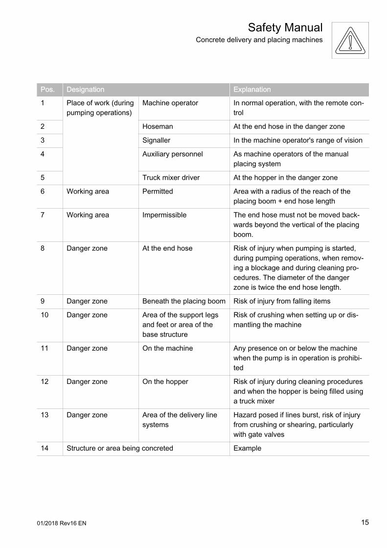
Pos. Designation Explanation
1 Place of work (duringpumping operations)
Machine operator In normal operation, with the remote con‐trol
2 Hoseman At the end hose in the danger zone
3 Signaller In the machine operator's range of vision
4 Auxiliary personnel As machine operators of the manualplacing system
5 Truck mixer driver At the hopper in the danger zone
6 Working area Permitted Area with a radius of the reach of theplacing boom + end hose length
7 Working area Impermissible The end hose must not be moved back‐wards beyond the vertical of the placingboom.
8 Danger zone At the end hose Risk of injury when pumping is started,during pumping operations, when remov‐ing a blockage and during cleaning pro‐cedures. The diameter of the dangerzone is twice the end hose length.
9 Danger zone Beneath the placing boom Risk of injury from falling items
10 Danger zone Area of the support legsand feet or area of thebase structure
Risk of crushing when setting up or dis‐mantling the machine
11 Danger zone On the machine Any presence on or below the machinewhen the pump is in operation is prohibi‐ted
12 Danger zone On the hopper Risk of injury during cleaning proceduresand when the hopper is being filled usinga truck mixer
13 Danger zone Area of the delivery linesystems
Hazard posed if lines burst, risk of injuryfrom crushing or shearing, particularlywith gate valves
14 Structure or area being concreted Example
Safety ManualConcrete delivery and placing machines
01/2018 Rev16 EN 15
1.1.19.3 Place of work
The place of work is the area in which people must remain in order tocarry out the work.
Place of work – machine operator
The machine operator's place of work is with the remote control whenthe pump is in operation. The place of work must be selected so as toallow visual contact with the placement site and the truck mixer driver,and so that the working area can be observed at the same time. Asignaller must otherwise be used.
The machine operator's place of work is with the machine when thisis being set up or prepared for driving.
Place of work – hoseman
The hoseman's place of work is within the danger zone of the endhose, but not beneath the placing boom. This requires a greater levelof caution. The hoseman and machine operator must have visualcontact.
Place of work – truck mixer driver
The truck mixer driver's place of work is in the danger zone of thehopper and at operating elements for the agitator and truck mixer.This requires a greater level of caution. The truck mixer driver andmachine operator must have visual contact.
1.1.19.4 Working area
The working area is the area in which work is carried out with or onthe machine. Parts of the working area can become danger zones de‐pending on the operation being carried out and the position of theplacing boom.
The working area must be secured and clearly identified. Suitablepersonal protective equipment is required in the working area. Themachine operator is responsible for safety in the working area of themachine whilst the machine is in use.
Safety ManualConcrete delivery and placing machines
16 01/2018 Rev16 EN
Impermissible working area
Because of their high manoeuvrability, some placing booms can alsobe shifted into positions for which they are not designed. This mayoverload or damage the placing boom. Placing booms must thereforeonly be moved within the permitted working area. (Impermissibleworking area P. 22)
1.1.19.5 Danger zone
The danger zone is the area surrounding the machine, in which peo‐ple may be at risk of injury from movements required by the work.
The danger zone varies within the working area and depends on theactivity being carried out and the position of the placing boom, if oneis present. Danger zones must be secured and clearly identified. Themachine operator must be capable of seeing the danger zone at alltimes and under all circumstances. If necessary, he must appoint asignaller to supervise the danger zone.
Depending on the working situation, places of work may occasionallyfall within the danger zone, especially the place of work of the hose‐man and the truck mixer driver. If a place of work falls within the dan‐ger zone, increased caution is required and suitable personal protec‐tive equipment is prescribed. Persons who are authorised to be pres‐ent in such a place of work must use their own discretion to assessdangerous situations and be able to react according to the situation.
The machine operator is responsible for safety in the danger zone ofthe machine whilst the machine is in use.
The machine operator must stop work immediately and press theEMERGENCY STOP button if an unauthorised person enters thedanger zone.
Support legs and support feet
There is a risk of crushing in the swingout and extension zone for thesupports.
Placing boom
The danger zone when working with the placing boom is the zoneover which the placing boom is slewed. In this area there is a risk ofinjury from falling concrete and delivery line components.
Safety ManualConcrete delivery and placing machines
01/2018 Rev16 EN 17
Machine
All the time the vehicle is in operation, there is a risk of injury on andbelow the machine from moving parts and bursting delivery lines orhydraulic hoses, as well as a risk of falling on slippery surfaces orsteps.
End hose
The danger zone when pumping is started, during pumping opera‐tions, when removing a blockage and during cleaning procedures isthe area around the end hose in which the end hose may swing out.The diameter of the danger zone is twice the end hose length.
Hopper
In the area of the hopper, there is a risk of becoming trapped betweenthe truck mixer and the hopper and of being sprayed with concrete.There is a risk of being crushed and of injury by shearing from thetransfer tube. There is a risk of becoming caught in the rotating agita‐tor.
Delivery line systems
In the area around the delivery line systems there is a risk of injuryfrom the delivery line bursting if there is an abrupt rise in pressure.There is a risk of crushing and injury by shearing with devices integra‐ted in delivery line systems.
1.2 Designated use
The machine must only be operated as intended and in technicallyperfect condition. All protective and safetyoriented devices, particular‐ly removable protective devices and EMERGENCY STOP devices,must be available and fully functional.
The machine is designed exclusively for the delivery and placing ofconcrete up to a bulk density of 2400 kg/m3. It must only be used forpumping operations on construction sites. The maximum deliverypressure must not exceed that specified on the rating plate or in thecheck book.
Safety ManualConcrete delivery and placing machines
18 01/2018 Rev16 EN
You must also observe the Operating Instructions and comply withthe intervals and conditions for inspections (particularly retesting) andmaintenance work in order to operate the machine within the limits ofits proper use.
1.2.1 Retesting (safety inspection)
After initial commissioning of the machine, the operational safety ofthe machine must be checked regularly by a subject expert. The in‐spection intervals depend on the age of the machine. The older themachine, the greater the probability of damage. For this reason, regu‐lar retesting of the machine, appropriate to its age, must be carriedout in order to detect damage in good time. Retesting should be car‐ried out in accordance with the inspection intervals listed below.
Retesting must consist of the following:● Retesting of the condition of the components and equipment with
regard to the formation of cracks, damage, wear, corrosion andother changes;
● Retesting of the completeness and effectiveness of the safetyequipment;
● Retesting to find out whether any defects which are found duringthe tests mentioned above and which could affect safety havebeen adequately rectified.
Furthermore, information provided by the manufacturer to the opera‐tor with reference to special instructions for maintenance and inspec‐tion must be observed.
1.2.2 Inspection intervals for retesting
The inspection intervals are fixed as follows:● Machines up to and including 5 years old:
Inspect after every 1000 operating hours or 1 year, whichever issoonest. The interval is repeated after every retest.
● Machines more than 5 years old:Inspect after every 500 operating hours or 1 year, whichever issoonest. The interval is repeated after every retest.
● Machines more than 10 years old:Inspect after every 250 operating hours or 1 year, whichever issoonest. The interval is repeated after every retest.
Safety ManualConcrete delivery and placing machines
01/2018 Rev16 EN 19
The day of initial commissioning in accordance with the handover re‐port and the machine's operating hours meter are definitive for the in‐tervals. This operating hours meter records the hours of pumping op‐erations. The operating hours meter must always be kept in goodworking order. It must not be tampered with. For machines without anoperating hours meter, the operating hours must be recorded in atraceable form in writing.
Retesting must be arranged by the operator. The results of retestingmust be entered in the check book and signed. The check book mustalways be kept with the machine and must be produced upon the re‐quest of the national supervisory bodies.
Notwithstanding national legislation, the operator can be liable in theevent of damage, if it is proved that the damage has arisen as a con‐sequence of regular retesting not being properly carried out.
If retesting is not carried out, the manufacturer will assume that themachine has been shut down. When the machine is restarted, retest‐ing must be carried out.
1.3 Improper use
Improper use is defined as use which is not described in or goes be‐yond that described in the “Designated use”, (Designated use P. 18)section. The manufacturer accepts no liability for damage resultingfrom such use. Some examples of conceivable improper uses are giv‐en below.
1.3.1 Transporting goods
The machine must not be used for the transport of goods, except forcarrying the accessories used for the machine, such as pipes, hoses,etc. The maximum permissible gross weight may not be exceeded.
Safety ManualConcrete delivery and placing machines
20 01/2018 Rev16 EN
1.3.2 Lifting loads
The placing boom must never be used for lifting loads.
1.3.3 Removing obstacles
The placing boom must not be used under any circumstances to re‐move obstacles. This would overload the placing boom, causing dam‐age and endangering people.
1.3.4 Extending the reach
It is forbidden to attach an extension to the end hose or boom tip ofthe placing boom (e.g. freely suspended transition liner) in order toextend the reach or in order to be able to pump “around corners”.Since the placing boom and the lifting equipment for the extensionhave differing pivot points and modes of control, it is not possible toco-ordinate their movements.
1.3.5 Extending the placing boom and end hose
Extension of the placing boom and end hose beyond the length speci‐fied on the rating plate is forbidden.
If the manufacturer defines the weight rather than the length of theend hose, you can use a reducer pipe with a longer end hose, for ex‐ample. The quoted gross weight must not be exceeded. (End hoseP. 43)
When using a longer end hose, the diameter of the danger zone alsoincreases. (End hose P. 43)
End hoses with a length of more than 4 m must not be guided byhand.
Safety ManualConcrete delivery and placing machines
01/2018 Rev16 EN 21
1.3.6 Impermissible end hose
There must be no couplings, spouts, discharge stops or other itemsfixed to the outlet end of the end hose unless they are approved bythe manufacturer.
1.3.7 Impermissible working area
During pumping operations, the end hose must not be moved back‐wards beyond the vertical axis of rotation of the placing boom.
Safety ManualConcrete delivery and placing machines
22 01/2018 Rev16 EN
In addition to this, additional impermissible working areas exist, de‐pending on the machine model and manufacturer, which are descri‐bed in the Operating Instructions.
1.3.8 Climbing the placing boom
It is prohibited to climb the placing boom, to stand on top of it or tomisuse it as a working platform or climbing aid.
1.3.9 Highpressure delivery
It is prohibited to deliver concrete at high pressure (concrete pressuregreater than 85 bar) through the delivery line of the placing boom. De‐livery line elements are marked with the maximum permissible deliv‐ery pressure. The delivery line and end hose are only suitable forconcrete pressures of up to 85 bar until the wear threshold isreached. For the wear threshold, refer to the Operating Instructionsfor the machine.
1.3.10 Accessories and attachments
It is prohibited to fit accessories and attachments to the machine ifthey have not been expressly approved for use on this machine bythe manufacturer.
1.3.11 Changes to the machine
You are not allowed to carry out your own changes to the machine.Changes must always be approved by the manufacturer.
Safety ManualConcrete delivery and placing machines
01/2018 Rev16 EN 23

1.4 Exclusion of liability
Where the manufacturer's delivery conditions are agreed, liability willbe as described in the provisions there. The manufacturer is not liablefor damage in cases specified there.
Unless the responsibility of the manufacturer, the warranty will be in‐validated in the following situations in particular:● use contrary to designated use.● incorrect operation, maintenance and repair.● use of spare parts or accessories other than original manufactur‐
er's spare parts and accessories or their equivalents.● conversions, alterations or modifications to the machine.● fitting of accessories and attachments not approved by the manu‐
facturer.● adjustment of safety pressures, speeds of movement, power out‐
puts, speeds of rotation and other settings to values other thanthose set in the works.
1.5 Personnel
The operator must ensure that only persons who are qualified or havereceived the necessary instruction work on or with the machine. It isthe responsibility of the operator to carry out regular (e.g. annual)safety briefings for their employees. Suitable training can be reques‐ted from the machine manufacturer. The operator must clearly definewho is responsible for operation and maintenance of the machine.The operating company must also ensure that only persons commis‐sioned to work on the machine do so. In addition, the operator shouldprovide the necessary personal protective equipment.
1.5.1 Requirements
Persons operating or carrying out maintenance work on the machinemust meet the following requirements:● They must be aged 18 years or over.● They must be physically and mentally capable.● They must be physiologically capable (rested and not under the in‐
fluence of alcohol, drugs or medication).● They must have been instructed in the operation and maintenance
of the machine.
Safety ManualConcrete delivery and placing machines
24 01/2018 Rev16 EN
● They must have demonstrated their competence to the operator.● They can be expected to reliably execute the tasks with which they
are charged.
The operating personnel must not wear loose garments or jewellery,including rings. Long hair which is not tied back must be covered by ahair net. There is a risk of injury, in particular from being caught ortrapped by moving parts.
All persons working on or with the machine must concentrate on thetask at hand and not be distracted, particularly by smartphones andmusic played through headphones.
1.5.2 Qualifications
Persons who are being trained, introduced and instructed in the useof the machine are only permitted to operate the machine under theconstant supervision of experienced personnel.
If you do not have qualified personnel, suitable workshop equipment,etc. available, you should commission the manufacturer's After SalesDepartment with the maintenance of your machine.
1.5.3 Responsibility of the machine operator
The operator must define the responsibility of the machine operator(including in respect to national road traffic regulations) and empowerthe machine operator to reject instructions from third parties prejudi‐cial to safety. The machine operator must be able to reject the site ofoperations in the event of doubts regarding technical safety.
1.6 Operating Instructions, operating procedures andother regulations
1.6.1 Operating Instructions
Personnel that are authorised to work on the machine must have readthe Operating Instructions, particularly the “Safety Regulations” sec‐tion, and the Safety Manual before working with the machine. Read‐ing the instructions after work has begun is too late. This applies es‐pecially to persons working only occasionally on the machine, e.g.during setting up or maintenance.
Safety ManualConcrete delivery and placing machines
01/2018 Rev16 EN 25
As the operator, you must always make sure that the Operating In‐structions are available. The Operating Instructions and check bookmust always be kept to hand at the site of use of the machine (in thetool compartment or container provided for this purpose).
As the operator, you must have personnel working on the machineconfirm in writing their knowledge, understanding and application ofthe Operating Instructions and Safety Regulations and Safety Man‐ual. At regular intervals of at least once a year, check that personnelare conscious of safety and the hazards involved in their work andare taking account of the Operating Instructions.
Personnel entrusted with work on the machine must observe all safe‐ty instructions and hazard warnings, and must be familiar with themachine itself. You must practice all the operating procedures descri‐bed in the Operating Instructions (extending the supports, operatingthe placing boom, shifting the placing boom into the driving position,preparing the vehicle for moving, etc.) under the supervision of a sub‐ject expert until you are certain you can execute them safely. Askquestions if there is something you have not understood. Begin oper‐ating the machine only once you are fully and explicitly familiar withthe layout and significance of all the control and monitoring devicesand the method of operation of the machine.
1.6.2 Operating procedures
The operator must produce operating procedures for their personnelin accordance with national regulations. These operating proceduresmust also contain instructions (including the obligation to provide su‐pervision and reports) concerning the observance of special opera‐tional features, particularly in respect of work organization, workingprocedures or personnel deployment. Furthermore, reference mustbe made to other generally valid legal and otherwise mandatory regu‐lations relating to accident prevention and environmental protection.Such regulations may also deal with handling hazardous substances,the issuing and wearing of personal protective equipment or with na‐tional road traffic regulations. You should familiarise yourself with thesite of operations and with how to use fire extinguishers. Observe thefirealarm and fire-fighting procedures.
Safety ManualConcrete delivery and placing machines
26 01/2018 Rev16 EN
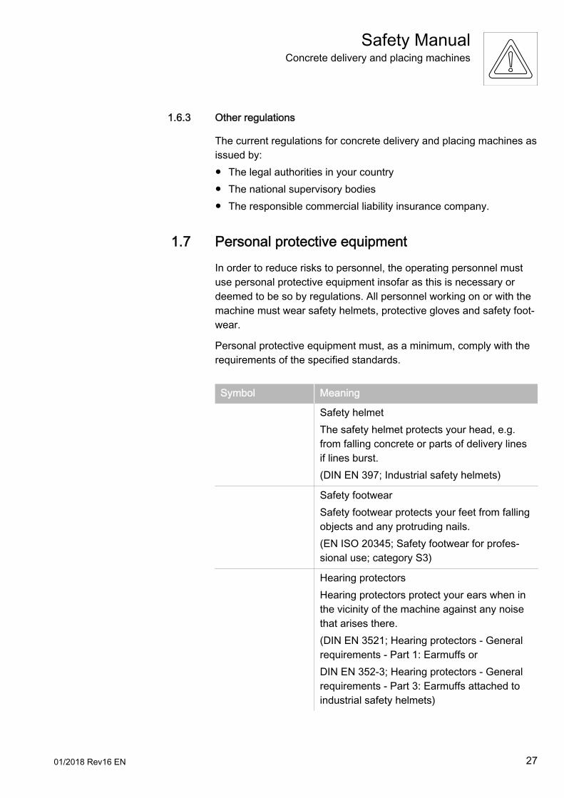
1.6.3 Other regulations
The current regulations for concrete delivery and placing machines asissued by:● The legal authorities in your country● The national supervisory bodies● The responsible commercial liability insurance company.
1.7 Personal protective equipment
In order to reduce risks to personnel, the operating personnel mustuse personal protective equipment insofar as this is necessary ordeemed to be so by regulations. All personnel working on or with themachine must wear safety helmets, protective gloves and safety foot‐wear.
Personal protective equipment must, as a minimum, comply with therequirements of the specified standards.
Symbol Meaning
Safety helmetThe safety helmet protects your head, e.g.from falling concrete or parts of delivery linesif lines burst.(DIN EN 397; Industrial safety helmets)
Safety footwearSafety footwear protects your feet from fallingobjects and any protruding nails.(EN ISO 20345; Safety footwear for profes‐sional use; category S3)
Hearing protectorsHearing protectors protect your ears when inthe vicinity of the machine against any noisethat arises there.(DIN EN 3521; Hearing protectors - Generalrequirements - Part 1: Earmuffs orDIN EN 352-3; Hearing protectors - Generalrequirements - Part 3: Earmuffs attached toindustrial safety helmets)
Safety ManualConcrete delivery and placing machines
01/2018 Rev16 EN 27
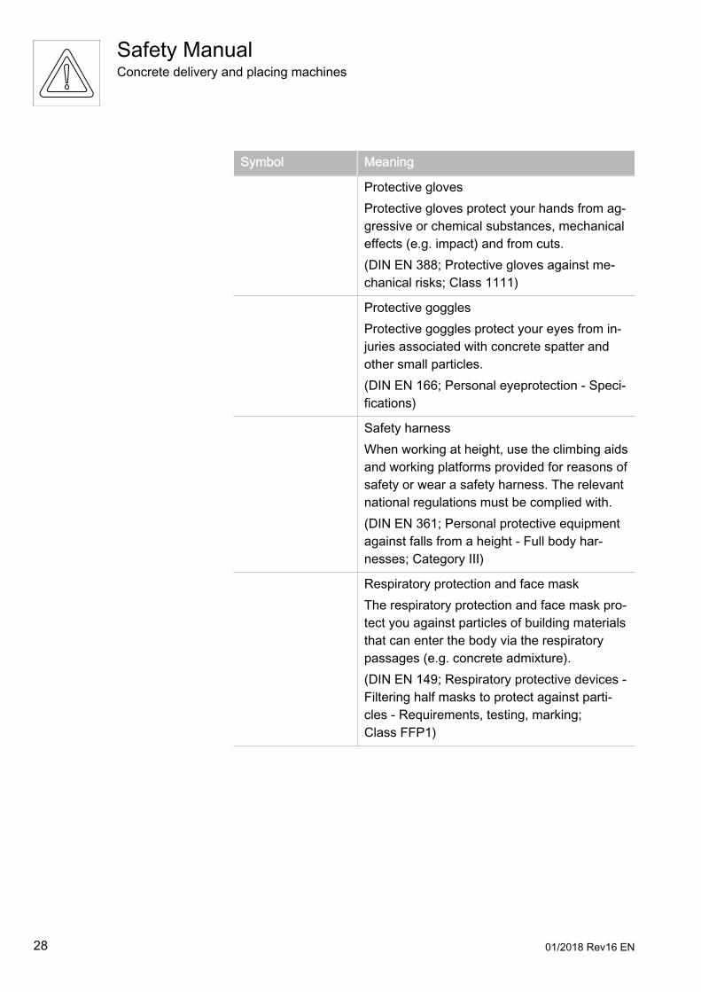
Symbol Meaning
Protective glovesProtective gloves protect your hands from ag‐gressive or chemical substances, mechanicaleffects (e.g. impact) and from cuts.(DIN EN 388; Protective gloves against me‐chanical risks; Class 1111)
Protective gogglesProtective goggles protect your eyes from in‐juries associated with concrete spatter andother small particles.(DIN EN 166; Personal eyeprotection - Speci‐fications)
Safety harnessWhen working at height, use the climbing aidsand working platforms provided for reasons ofsafety or wear a safety harness. The relevantnational regulations must be complied with.(DIN EN 361; Personal protective equipmentagainst falls from a height - Full body har‐nesses; Category III)
Respiratory protection and face maskThe respiratory protection and face mask pro‐tect you against particles of building materialsthat can enter the body via the respiratorypassages (e.g. concrete admixture).(DIN EN 149; Respiratory protective devices -Filtering half masks to protect against parti‐cles - Requirements, testing, marking;Class FFP1)
Safety ManualConcrete delivery and placing machines
28 01/2018 Rev16 EN
2 Setting up and working with the machine
Safety ManualConcrete delivery and placing machines
01/2018 Rev16 EN 29

30 01/2018 Rev16 EN
2.1 Before working with the machine
2.1.1 Checking that the machine is ready for operation
As machine operator, it is your responsibility to check the machine forexternal damage and defects before any use of the machine. Youmust immediately report any changes (including changes in the work‐ing characteristics) to the organisation or person responsible. If nec‐essary, shut the machine down immediately and secure it.
2.1.2 Rendering the machine ready for operation
As machine operator, you are responsible for rendering the machineready for operation. This also includes topping up the functional flu‐ids. Do not fill with fuel in enclosed spaces. Switch off the engine andthe heating. Wipe up spilt fuel immediately. Do not smoke or use anaked flame when handling fuel.
Set all the control and monitoring devices to the zero position beforeyou change the mode of control (control block, control console or re‐mote control).
Never put the remote control down when the machine is ready for op‐eration. If this is unavoidable in exceptional cases, you must switchoff the remote control, disconnect it and lock it away.
Never leave the machine when the engine is running or when the en‐gine could be started by an unauthorised person. If you need to leavethe machine, proceed as follows:
● Switch off the remote control.● Disconnect the remote control and lock it away.● Switch off the ignition or the main switch.● Lock the control cabinet.
2.2 Danger due to high voltage
2.2.1 High-voltage lines
Whenever you touch a high-voltage line, there is a risk of death for allpersons either on the machine or in its vicinity or who are connectedto it (via the remote control, end hose, etc.). A spark can jump acrossfrom a highvoltage line even if you just approach it and this will ener‐gise the machine and the surrounding area.
Safety ManualConcrete delivery and placing machines
01/2018 Rev16 EN 31
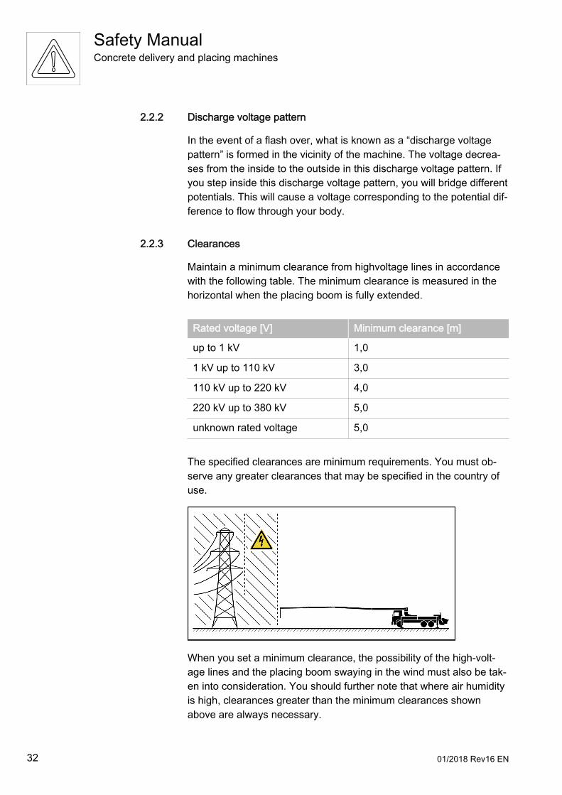
2.2.2 Discharge voltage pattern
In the event of a flash over, what is known as a “discharge voltagepattern” is formed in the vicinity of the machine. The voltage decrea‐ses from the inside to the outside in this discharge voltage pattern. Ifyou step inside this discharge voltage pattern, you will bridge differentpotentials. This will cause a voltage corresponding to the potential dif‐ference to flow through your body.
2.2.3 Clearances
Maintain a minimum clearance from highvoltage lines in accordancewith the following table. The minimum clearance is measured in thehorizontal when the placing boom is fully extended.
Rated voltage [V] Minimum clearance [m]
up to 1 kV 1,0
1 kV up to 110 kV 3,0
110 kV up to 220 kV 4,0
220 kV up to 380 kV 5,0
unknown rated voltage 5,0
The specified clearances are minimum requirements. You must ob‐serve any greater clearances that may be specified in the country ofuse.
When you set a minimum clearance, the possibility of the high-volt‐age lines and the placing boom swaying in the wind must also be tak‐en into consideration. You should further note that where air humidityis high, clearances greater than the minimum clearances shownabove are always necessary.
Safety ManualConcrete delivery and placing machines
32 01/2018 Rev16 EN
You must stand as close as possible to the unfolded placing boom ifyou wish to correctly estimate the movements of the boom and,above all, the clearance between the placing boom and obstacles orhigh-voltage lines.
The same minimum clearances are necessary when driving underoverhead cables.
In the event that this minimum clearance cannot be maintained underall possible working positions, the power station responsible must becontacted and you must have the highvoltage line switched off.
Should you have any doubts, it is better to forgo the use of the plac‐ing boom and to lay a separate delivery line, for instance.
2.2.4 Highvoltage warning devices
According to the current rules of engineering, highvoltage warning de‐vices do not meet a safety standard which enables minimum clearan‐ces to highvoltage lines that are smaller than the required minimumclearances to be used. Previous experience has shown that highvolt‐age warning devices cannot make all situations in working proce‐dures safe. Flash overs and fatal accidents can occur despite the useof a highvoltage warning device. You must therefore always maintainthe minimum clearances mentioned above.
2.2.5 Procedure in the event of a flash over
If, despite all precautions, a flash over occurs, stay calm and do notmove (potential differential) or touch anything.
Safety ManualConcrete delivery and placing machines
01/2018 Rev16 EN 33
If your machine comes into contact with high-voltage lines:● Warn people standing outside the area not to approach or touch
the machine.● Have the power switched off.● Only leave the machine once you are sure that the line you have
touched or damaged has been deenergised.
Electricity generator works are always equipped with automatic start‐up systems. If a circuit breaker trips, the short-circuited line will beswitched back on again after a brief interval. Brief intervals where thevoltage is absent create a false sense of safety.
You must not move or rescue injured persons until a representative ofthe power station has notified you that the line has been switched off.
A radio remote control system only protects the machine operator ifhe is standing outside the discharge voltage pattern.
2.2.6 Earthing in the event of electrostatic charging
Working in the vicinity of transmitters (radio transmitter, etc.) can re‐sult in faults in the radio remote control system and dangerous electri‐cal charges in the machine. Persons who bridge the charged parts tothe earth are heavily charged on contact.
Machines in use in the vicinity of transmitters must be earthed. Thisearthing may be carried out by trained personnel.
Even with an earthed machine, the safe clearances to high-voltagelines (Clearances P. 32) and the instructions relating to storms andbad weather (Procedure in storms P. 45) must be complied with.
If you have any further questions about earthing the machine, pleasecontact site management or the operator of the machine.
2.2.7 Earthing on construction sites with special equipment
When carrying out work in the area of special installations (particular‐ly overhead lines for railways or substations), it may be the case thatthe machine needs to be earthed upon request and in consultationwith the operator of the special installation. This earthing must only becarried out by qualified personnel.
Even with an earthed machine, the safe clearances to high-voltagelines (Clearances P. 32) and the instructions relating to storms andbad weather (Procedure in storms P. 45) must be complied with.
Safety ManualConcrete delivery and placing machines
34 01/2018 Rev16 EN
2.3 Stationary machines
2.3.1 Setup site
Stationary machines are generally used on a construction site for alengthy period. For this reason, site management should prepare thesetup site carefully. Site management must deliver the necessarydocuments in good time in order to be able to prepare the founda‐tions, base plates or similar on time.
When selecting the setup site, remember that the machine must bedismantled and transported away again at the end of its use on site.The ambient conditions may change as construction work progress‐es.
Please also observe the (Setup site P. 36) section.
2.3.2 Stationary placing booms
Stationary placing booms can be erected on tubular columns, latticebooms or other base structures. The base/structural elements towhich the base structure is fixed must be able to withstand the forcesand moments transferred via the base structure, as specified in themanufacturer’s information. The base frame of the base structuremust be fastened in place so that it is level on the base/structural ele‐ments in every direction. Check the documentation provided by themanufacturer in this regard and the corresponding notes in the oper‐ating instructions.
2.3.3 Lifting machines and components
Machines which are transported to the setup site in individual parts ornot under their own power must only be lifted with suitable liftingequipment in accordance with the specifications in the Operating In‐structions. The lifting gear on the machine must be capable of accept‐ing the lifting equipment and lifting the load. Noone should stand un‐der suspended loads. Before work is started, a subject expert mustcheck that the assembled machine is working properly.
2.3.4 Loading and transporting
Only use suitable means to load and transport stationary machines.Ensure that noone can be injured by the machine tipping over or slip‐ping.
Safety ManualConcrete delivery and placing machines
01/2018 Rev16 EN 35
If there are transport fixtures provided for the machine or its individualcomponents, only these should be used. The machine/componentsmust be properly secured during transport. The transport vehicle andmachine must be marked to conform with the road traffic regulationsin the country concerned if they are to use the public highway.
Please also observe the (Driving P. 39) section.
2.4 Mobile machines
2.4.1 Setup site
Site management must prepare and assign the set-up site. It is themachine operator who takes responsibility for setting up the machinesafely. The machine operator must inspect the setup site proposed bysite management and must refuse to set the machine up at the site ofoperations if there are any doubts regarding safety.
As machine operator, you must familiarise yourself with the workingarea and surroundings before work is begun. The working area andsurroundings include, in particular, obstacles in the work and travel‐ling areas, the load-bearing capacity of the supporting ground andany barriers separating the construction site from public roads.
The setup site must have sufficient lighting to ensure safe operationof the machine. Ensure that the setup site is adequately lit.
Do not set up the machine in areas where equipment may fall down.
Incidents of overlapping with the working areas of other machines(particularly cranes, other placing booms, etc.) should be avoided asfar as possible. If this is not possible, special care and attention is re‐quired when setting up and operating machinery. If necessary, youmust use a signaller.
You must also check the approach route to the site where the ma‐chine will be set up. If you are unsure whether the approach route issuitable, prepare the route before work is started. It is especially nec‐essary to walk the approach route once in darkness and at dusk ordawn. You should repeat this exercise again before leaving the con‐struction site.
Always ask for a signaller if you need to reverse. If necessary, havethe approach route closed off or secured by signallers. Have any ma‐terials or equipment that hinder your approach removed.
Safety ManualConcrete delivery and placing machines
36 01/2018 Rev16 EN
2.4.2 Supporting ground
Find out the load-bearing capacity of the supporting ground. The sitemanagement will be able to state the permitted ground pressure. Ifthe load-bearing capacity is unknown, assume the that worst casescenario applies.
The supporting ground must be level and even. If necessary, set up alevel surface on top of the uneven ground. There must be no voids orother ground irregularities under the support feet. Asphalt, concreteslabs, etc. may have been washed out underneath. Never set the ma‐chine up on backfilled ground, obvious or known voids or unevenground.
The support area must be enlarged as required. Support plates andtimber blocks may be used to increase the support area. The sup‐ports must be undamaged and free from ice, oil, grease, etc. Thesupport blocks and timber blocks must be laid under the supportplates such that the load is distributed uniformly and the support legcannot slip off the side of the support.
Check the stability of the machine regularly during operation. Interruptthe pumping operation if the machine becomes unstable.
Factors which reduce stability include, for instance:● Modifications to the ground conditions, particularly caused by rain
water or the thawing of frozen ground● The support sinking on one side● Fluid losses through leaks in the support hydraulics
Safety ManualConcrete delivery and placing machines
01/2018 Rev16 EN 37
2.4.3 Corner bearing loads
The corner bearing load is stated on each support leg. This valuemust always be legible.
The load supported by each support leg is conically diffused in theground at an angle of 45 °. Safe clearance to the pits and slopes mustbe maintained, and such clearance must be determined in accord‐ance with the nature of the ground. The safe clearance is measuredfrom the foot of the pit.
On undisturbed, compacted ground, the safe clearance correspondsto the pit depth, but must be at least 2 m.
On loose or backfilled ground, the safe clearance corresponds to dou‐ble the pit depth, but must be at least 2 m.
2.4.4 Supports
The placing boom must not be raised until the machine has been sup‐ported in accordance with the Operating Instructions. There is other‐wise a risk of the machine toppling over.
Swing out and telescope the support legs to their end positions in se‐quence. Intermediate positions are prohibited to guarantee stability.Exceptions are machines which have been equipped by the manufac‐turer with a device which allows secure erection with a reduction insupport. Check the corresponding notes in this regard in the operat‐ing instructions.
Safety ManualConcrete delivery and placing machines
38 01/2018 Rev16 EN
Do not carry out more than one movement at a time. If a movement isstopped, the entire volume of fluid is available for the remainingmovements, and can increase their speeds. Depending on the de‐sign, it may be the case that carrying out several movements at once(as opposed to carrying out a single movement at maximum speed atany one time) does not bring any advantage in terms of time. Carry‐ing out several movements at once requires an increased level of at‐tentiveness.
Lock all supports mechanically, if this is provided for in the design.Close all shut-off valves in the support hydraulics. Leaks can causethe supports to sink on one side.
The machine must be made level in all directions. Provided the manu‐facturer does not state otherwise, the maximum permissible deviationfrom the horizontal is 3 °. Greater deviations from the horizontal over‐load the slewing gear for the placing boom as well as its overall sup‐port structure, jeopardising the stability of the machine.
Check stability regularly during operation. The elastic distortions tothe machine frame occasionally occurring under extreme positions ofthe placing boom (one support foot lifts from the ground) must becompensated for by resetting the support cylinders until all supportfeet are firmly placed on the ground.
2.4.5 Driving
When preparing the machine for driving, you must perform the follow‐ing tasks in particular:● The placing boom must be folded in fully and positioned on the
placing boom support provided.● The support legs and support feet must be fully retracted and se‐
cured.● Raised or locked axles must be lowered and released.
Safety ManualConcrete delivery and placing machines
01/2018 Rev16 EN 39
● Accessories and moving parts belonging to the machine must besafely stowed/secured.
● The maximum permissible gross weight must not be exceeded.
While the vehicle is being driven, the delivery line, pump and hoppermust be empty. If there is concrete residue in the hopper, there is arisk of injury from the concrete residue, which may be thrown outwhile the vehicle is in motion. This also affects the centre of gravity ofthe machine. Observe the road traffic regulations and specificationsof the machine manufacturer.
Maintain a distance of at least 1 m to the secured edges of the pit anda distance of at least 2 m to slopes.
Always make sure that there is sufficient clearance when driving un‐der underpasses, over bridges and through tunnels or when passingunder overhead cables. The same minimum clearances apply whendriving under high-voltage lines as when working with the placingboom. Be aware of the height of the truck. Only drive over arches,bridges or other supporting structures if their load-bearing capacity issufficient.
Do not drive across uphill or downhill gradients. Be aware of the ele‐vated position of the truck's centre of gravity when travelling on aslope and on ascending or descending routes. Always adapt yourtravelling speed to the prevailing conditions on sloping terrain.
Observe national road traffic regulations. If necessary, clean thetyres, lights and number plate. Before travelling with the machine,check that the braking, steering, signalling and lighting systems arefully functional.
Persons accompanying the driver must be seated on the passengerseats provided for this purpose.
Safety ManualConcrete delivery and placing machines
40 01/2018 Rev16 EN
For truck mixer concrete pumps, only turn the mixer drum at the maxi‐mum specified speed of rotation whilst the truck is in motion. Thetruck is at risk of toppling over, particularly when travelling round cor‐ners.
2.4.6 Towing
The machine must only be towed, loaded and transported in accord‐ance with the Operating Instructions. Only use existing towing hitchesfor towing and observe the truck manufacturer's regulations.
You must comply with the prescribed driving position, permittedspeed and itinerary when towing.
2.4.7 Loading
Many lifting points fitted to the machine are provided for assemblypurposes only. They are not suitable for lifting the complete machine.The lifting points for lifting the entire machine are specially marked.
Use only appropriate means of transport and lifting equipment of ade‐quate load-bearing capacity. Lifting equipment, lifting tackle, supporttrestles and other auxiliary equipment must be reliable and safe in op‐eration.
Use only stable loading ramps of adequate load-bearing capacity forloading. Ensure that noone is at risk from the machine tipping over orslipping.
Secure the machine on the transport vehicle to prevent it rolling away,slipping and toppling over.
Safety ManualConcrete delivery and placing machines
01/2018 Rev16 EN 41
2.5 Placing booms
2.5.1 Unfold placing boom
Only raise a mobile placing boom from the driving position once themachine has been supported in accordance with the Operating In‐structions. Stationary placing booms may only be raised after theproper set-up has been checked by a subject expert.
Only raise the placing boom in the sequence described in the Operat‐ing Instructions. The correct sequence depends on the “Folding sys‐tem” (roll-and-fold system, Z fold system, etc.).
Do not carry out more than one movement at a time. If a movement isstopped, the entire volume of fluid is available for the remainingmovements, and can increase their speeds. Depending on the de‐sign, it may be the case that carrying out several movements at once(as opposed to carrying out a single movement at maximum speed atany one time) does not bring any advantage in terms of time. Carry‐ing out several movements at once requires an increased level of at‐tentiveness.
The range of a radio remote control is long enough for the machine toreceive control commands (e.g. from a great distance, from inside en‐closed spaces) even without visual contact. If there is no visual con‐tact, for example, because you are changing workplace, you mustswitch off the remote control. If there is no visual contact, for exam‐ple, because the construction site is unclear, signallers MUST beused, and must remain in contact with the machine operator usingsuitable means, and have visual contact with the site of concreteplacement, work areas and danger zones, and the machine.
Always ask the site management to provide you with an assistant toact as a signaller. Agree clear hand signals or other signals with thesignaller so that you can communicate with each other. You shouldposition the signaller such that he can always observe the whole ofthe placing boom. Your primary duty as the machine operator is toobserve the site of concrete placement.
Only slew the placing boom over persons when the delivery line andend hose are empty. There is a risk of concrete falling out of the endhose.
Safety ManualConcrete delivery and placing machines
42 01/2018 Rev16 EN
Press the EMERGENCY STOP BUTTON immediately if the placingboom moves unexpectedly. If this should occur, you must ceaseworking and have the cause of the fault rectified by your qualified per‐sonnel or our After Sales Service personnel.
Placing booms with placing boom hinges which allow considerableflex angles have a very large potential working area. This high ma‐noeuvrability means different placing booms can also be moved intodangerous positions. Prohibited areas can be found in the OperatingInstructions.
There is a risk that you will damage the truck, truck superstructure orobstacles on the construction site with the placing boom. Under cer‐tain circumstances it is even possible to overload or cause damage tothe placing boom. Uncontrolled movements may result from the sud‐den, violent release of the placing boom after collisions. This may al‐so result in (possibly fatal) personal injury.
The manufacturer has indicated such impermissible working areas bythe use of warning signs and information plates on the machine andappropriate notes in the Operating Instructions.
2.5.2 End hose
The end hose must hang freely each time you start pumping, whenyou start pumping again after blockages, and during cleaning proce‐dures. Noone should stand within the danger zone of the end hose.
Safety ManualConcrete delivery and placing machines
01/2018 Rev16 EN 43
The diameter of the danger zone is twice the end hose length. Do notguide the end hose when pumping is started. There is a risk of acci‐dent from the end hose swinging out or stones being ejected.
When using a longer end hose, the diameter of the danger zone (Ex‐tending the placing boom and end hose P. 21) also increases.
End hoses with a length of more than 4 m must not be guided byhand.
There is a risk of injury to the hoseman if the end hose becomescaught in the reinforcement and suddenly jumps out on further move‐ment of the placing boom.
Never bend the end hose over. Never attempt to straighten a bentend hose by increasing the pressure. The end hose must not be sub‐merged below the surface of the concrete being delivered, otherwisethe concrete may spray upwards.
The concrete may also spray from the end hose due to the presenceof air in the delivery line. To prevent this from occurring, the hoppermust be filled with concrete at least as far as the agitator shaft so thatno air can be sucked in.
The end hose must be secured against falling.
2.5.3 Guiding the end hose ergonomically
The hoseman must guide the end hose in such a way that preventsexcess spraying of concrete, and so that concrete is directed precise‐ly into the site of concrete placement.
Control the placing boom so that the hoseman can guide the endhose without power consumption. The hoseman must not carry theend hose by hand, because the weight of it may cause permanentpersonal injury.
Safety ManualConcrete delivery and placing machines
44 01/2018 Rev16 EN
2.5.4 Connecting drills
If a drill is connected to the delivery line for the placing boom, it mustnot place any further strain on the placing boom. The placing boommust be connected to the drill in such a way that the placing boomdoes not require adjustment. There should be 1-2 delivery hoses be‐tween the placing boom and the drill; these must be secured so thatthey cannot move in an uncontrolled manner. If the drill is moved onthe construction site, the placing boom must not be connected.
2.5.5 Procedure in storms
Return the placing boom to the driving position or rest position in theevent of storms or bad weather.● Placing booms with a vertical reach of 42 m or more must only be
operated in winds of up to wind force 7 (wind speed 51 km/h).● Placing booms with a vertical reach of less than 42 m may only be
operated in winds of up to wind force 8 (wind speed 74 km/h).
The definitive wind speed is measured at the height of the boom tip.
Wind speeds in accordance with the Beaufort scale are average windspeeds measured over a period of 10 minutes. Higher speed gusts ofwind may occur briefly during the measuring period.
Higher wind speeds jeopardise the stability and safety of structural el‐ements. There is a risk of lightning strike in a thunderstorm.
Lightning strikes pose a risk of death. The machine and the surround‐ing area will be charged with electricity. Earthing the machine doesnot reduce this risk. For this reason, you should fold in the placingboom if there is a risk of lightning strike.
Tower cranes on construction sites generally have wind speed meas‐uring equipment, enabling you to find out the wind speed at any time.If no wind speed measuring equipment is available, you can ask thenearest meteorological office what the wind speed is, or estimate thewind speed using the following rule of thumb:● In winds of force 7 and greater, green leaves break from the trees
and there is perceptible resistance when walking against the wind.● In winds of force 8 and greater, small branches break from trees
and walking outside is significantly impeded.
Safety ManualConcrete delivery and placing machines
01/2018 Rev16 EN 45
2.5.6 Concreting in cold weather
Placing booms must not be used at temperatures of below minus15 °C (+5 °F) except with the express approval of the manufacturer.There is a danger of damage to the steel (brittle fracture) and theseals throughout the system at such extreme minus temperatures.
In addition, such minus temperatures should be considered the realis‐tic lower limit for concrete placement, as it is no longer possible toprepare concrete such that it can achieve its strength without the useof special additives.
2.6 Delivery line systems
2.6.1 Suitable delivery lines
Use only delivery lines, end hoses, couplings, etc. which are in per‐fect condition and suitable for the delivery job and have been ap‐proved by the machine manufacturer. Delivery lines are subject towear which varies according to the pressure and composition of theconcrete, the material from which the delivery line is made, etc.
If you are not responsible for the separate delivery lines, the permissi‐ble operating pressures of these should be confirmed by the operat‐ing company.
2.6.2 Securing delivery lines
Delivery lines, delivery hoses, end hoses and couplings must be se‐curely fastened and secured to prevent spontaneous opening.
Safety ManualConcrete delivery and placing machines
46 01/2018 Rev16 EN
2.6.3 Leak tightness and blockages
Regularly force water through the delivery line under operating pres‐sure to check that the system is watertight.
A properly cleaned delivery line is the best insurance against the for‐mation of blockages. Blockages increase the risk of accidents. Neverattempt to push through a blockage (e.g. by increasing the deliverypressure, using compressed air, etc.). There is a risk of death fromthe delivery line bursting or from concrete being ejected from the endof the delivery line.
Prevent blockages by adjusting the operating conditions. Removeblockages by reverse pumping and then restarting forward pumping.Repeat this process several times if necessary. If the blockage is notremoved, relieve the pressure on the delivery line before removingthe section of delivery line concerned.
Safety ManualConcrete delivery and placing machines
01/2018 Rev16 EN 47
2.6.4 Opening delivery lines
Delivery lines must not be opened or tapped off while they are pres‐surised. Concrete exiting under pressure can cause injury. The con‐crete column must be depressurised by reverse pumping before thedelivery line is opened. Never bend over the coupling when you areworking.
2.6.5 Clearance to delivery lines
Noone should remain in the vicinity of separate delivery lines duringpumping operations. Cordon off the danger zone. If it is not possibleto place a large enough cordon around the danger zone, the deliveryline must be covered by suitable means.
2.6.6 Securing the delivery lines
Delivery lines, in particular riser lines which are not laid along placingbooms, must be securely fastened in order to transfer the forces gen‐erated in them into the structure or other structural members. Thelines must be laid so as to avoid kinks, sharp bends, stresses anddamage during pumping operations.
2.6.7 Continuation delivery lines
If a continuation delivery line is connected to the placing boom, itmust not place any further strain on the placing boom.
While you connect, use and disconnect a continuation delivery line,you must switch off the placing boom control system to prevent unin‐tended movements of the placing boom. There is a risk of accidentposed by jerky movements of the boom tip.
Safety ManualConcrete delivery and placing machines
48 01/2018 Rev16 EN
2.6.8 Devices for shutting off, diverting and cleaning
During operation, there is a risk of being crushed and of injury byshearing. Hydraulically driven devices are generally supplied withpower by the hydraulic system of a machine. For this reason, theremust always be a line of sight between the devices and the machinefitted with the control unit. Observe the safety regulations for the ma‐chine and the device when connecting and operating a device. Beforeoperating devices, ensure that no persons are present in the dangerzone.
Use only devices that are suitable and in perfect working order to shutoff, divert and clean the delivery line. Defective and unsuitable devi‐ces can lead to damage to the entire delivery system and injure peo‐ple in the vicinity if they fail.
2.7 Pumping operations
2.7.1 Place of work
The machine operator's place of work is with the remote control whenthe pump is in operation. If you operate the machine using the remotecontrol, all operating and control devices on the machine must beclosed to prevent unauthorised access.
In the case of stationary placing booms, platforms or similar equip‐ment are only provided for assembly and maintenance work. Use ofthese platforms as a place of work during operation is prohibited.
It is forbidden to climb onto the machine during operation. In the caseof stationary placing booms, it is forbidden to climb ladders during op‐eration.
2.7.2 Safety
Before switching on or restarting the machine or individual machinefunctions, you must ensure that doing so will not endanger anyone'ssafety.
Refrain from any procedures that may impair the stability of the ma‐chine or are prejudicial to safety in any other way.
Safety ManualConcrete delivery and placing machines
01/2018 Rev16 EN 49
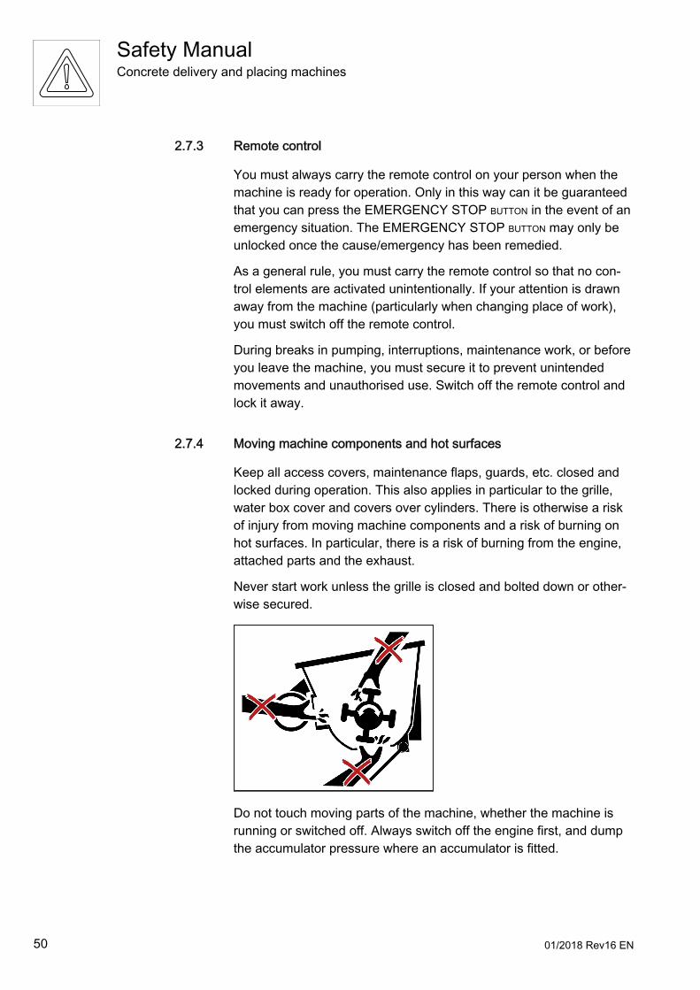
2.7.3 Remote control
You must always carry the remote control on your person when themachine is ready for operation. Only in this way can it be guaranteedthat you can press the EMERGENCY STOP BUTTON in the event of anemergency situation. The EMERGENCY STOP BUTTON may only beunlocked once the cause/emergency has been remedied.
As a general rule, you must carry the remote control so that no con‐trol elements are activated unintentionally. If your attention is drawnaway from the machine (particularly when changing place of work),you must switch off the remote control.
During breaks in pumping, interruptions, maintenance work, or beforeyou leave the machine, you must secure it to prevent unintendedmovements and unauthorised use. Switch off the remote control andlock it away.
2.7.4 Moving machine components and hot surfaces
Keep all access covers, maintenance flaps, guards, etc. closed andlocked during operation. This also applies in particular to the grille,water box cover and covers over cylinders. There is otherwise a riskof injury from moving machine components and a risk of burning onhot surfaces. In particular, there is a risk of burning from the engine,attached parts and the exhaust.
Never start work unless the grille is closed and bolted down or other‐wise secured.
Do not touch moving parts of the machine, whether the machine isrunning or switched off. Always switch off the engine first, and dumpthe accumulator pressure where an accumulator is fitted.
Safety ManualConcrete delivery and placing machines
50 01/2018 Rev16 EN
Do not insert any objects (shovel handle, trowel, etc.) into moving ma‐chine components. Such objects could become trapped and draggedinto the machine. They might then hit you or be torn from your handsand cause you injury.
2.7.5 Constant observation of the machine
You should be constantly observing the machine for any damage orfaults while it is in use. In the event of faults or malfunctions that im‐pair safety at work, shut the machine down immediately and secure it.Have the faults rectified immediately. If it is not possible to rectifyfaults which jeopardise the safe operation of the machine, you mustsuspend operations until the defects are rectified.
2.7.6 Truck mixer
As the machine operator, it is your role to instruct the truck mixer driv‐ers who deliver the concrete to you, so that they are able to operatethe operating elements on the concrete pump provided for their use.Only allow the truck mixer drivers to work alone once you are certainthat they have understood your instructions.
Make sure that no-one stands between the approaching truck mixerand the machine. There is a risk of crushing between the truck mixerand the machine.
2.8 Cleaning
2.8.1 General
You must drain the delivery line, pump and hopper completely. Con‐crete residue in the hopper, in particular, may be thrown out whilst thetruck is moving.
The machine must not be driven with the placing boom unfolded orthe support legs extended, even over short distances. This rule alsoapplies when you have to drive the machine to a different site forcleaning. The placing boom and support legs must be fully retractedand secured.
Safety ManualConcrete delivery and placing machines
01/2018 Rev16 EN 51
The preferred methods for cleaning the delivery line are reversepumping or forced cleaning with water. The agitator must be switchedon during reverse pumping. Otherwise, the concrete flowing back intothe hopper can bend the agitator shaft. Use a catch basket, pipecleaning head and wash-out ball for forced cleaning to prevent anywater from flowing into the formwork.
Never spray remote controls or control cabinets with barrier agents(mould oil or similar) to protect them against contamination. This cau‐ses significant corrosion damage to the electrical system.
There is a risk of injury at all points on the machine from slipping, trip‐ping, bumping into things, etc. Use the handles and steps to climb in‐to and out of the machine. It is forbidden to stand on the grille. Do notjump from the machine.
Do not reach into the hopper or any other moving machine compo‐nents. This rule must also be followed when you are opening the out‐let on the bottom of the hopper. Do not remove the grille.
Only point the water jet into the hopper or other moving machinecomponents. Do not insert the hose. It could become entangled withmoving machine components.
2.8.2 Cleaning agents
Take care when using aggressive cleaning agents. Aggressive clean‐ing agents may attack materials (e.g. rubber) and painted surfaces.You can use commercially available paint cleaning and care agents,as long as these have a pH value of between 4 and 9. Ask the manu‐facturer of the cleaning agent to confirm its suitability. Observe the
Safety ManualConcrete delivery and placing machines
52 01/2018 Rev16 EN
manufacturer's instructions regarding use and safe handling. Wearprotective clothing. Always rinse off cleaning agent thoroughly withclean water; do not allow puddles to form.
Do not use sea water or other water containing salt for cleaning pur‐poses.
Do not use any highly flammable agent for cleaning; there is a risk offire.
2.8.3 Cleaning with compressed air
When the delivery line is being cleaned with compressed air, there isan increased risk of accidents caused by compressed air escapingexplosively, spurting concrete, and delivery or end hoses moving un‐controllably if they have not been removed.
Compressed air should only be used for cleaning purposes under thesupervision of a subject expert. All persons participating in the clean‐ing procedure must be instructed in the safety regulations.
The manufacturer accepts no liability for damage caused by incorrect‐ly performed compressed air cleaning. You must observe the follow‐ing rules without fail when you use compressed air to clean out thedelivery line:● Individual pipes and short pipe runs up to 10 m in length must not
be blown through with compressed air. There is a risk of accidentfrom rebound.
● Only blow out delivery lines that have the same nominal diameterthroughout their length. Reducer pipes must be drained and flush‐ed out by hand.
● No bends, delivery or end hoses may be fitted at the end of the de‐livery line.
Safety ManualConcrete delivery and placing machines
01/2018 Rev16 EN 53
● A catch basket must be fastened at the end of the delivery line anda wash-out adaptor must be fitted on the head of the delivery line.The catch basket and washout adaptor must fit the delivery linesystem.
● The concrete must be able to flow freely from the end of the deliv‐ery line.
● There must be no persons present within an area of 3 m aroundthe delivery line, at the end of the delivery line and, in particular, infront of the opening in the catch basket.
● Care must be taken to ensure that any concrete that might be ex‐pelled from the catch basket cannot injure anybody or cause anydamage.
● The wash-out adaptor must be fitted with a separate, large dumpcock and a pressure gauge.
● The pressure gauge must be kept under constant observation dur‐ing the cleaning process. The pressure in the delivery line must berapidly dumped via the dump cock in the event of a sudden drop inpressure (concrete column exiting from the end of the line) or in‐crease in pressure (risk of blockage).
● The sponge ball or the plug used to push the concrete out must besufficiently dense that the air does not pass through it into the con‐crete. In addition, the delivery line must be sealed to the rear whenthe sponge ball or plug is caught in the catch basket.
● Only work on the delivery line (particularly when opening the deliv‐ery line) if it has been depressurised. Make sure that the com‐pressed air has been dumped completely.
● The dump cock must be opened in such a way that no-one can beinjured by concrete residue that might be expelled from the dumpcock.
● Separate delivery lines that are cleaned with compressed air mustbe securely fastened so that they cannot move uncontrollably.
● If continuing distribution systems (e.g. rotary distributors), gatevalves or other delivery line elements are connected to the deliveryline, they must be secured in such a way that they cannot moveuncontrollably.
2.8.4 Protection against water
Water spraying on the machine from random directions has no dam‐aging effect. The electrical system is protected against spray water,but is not waterproof.
Safety ManualConcrete delivery and placing machines
54 01/2018 Rev16 EN
You must close/seal all openings into which water/steam/cleaningagent must not penetrate for safety or functional reasons beforecleaning the machine with water or a steam jet (high-pressure clean‐er) or other cleaning agents. Electric motors and control cabinets areparticularly at risk.
2.8.5 Post-cleaning procedure
After the machine is cleaned, the covers/tapes must be completely re‐moved and the machine must be checked to ensure that it is ready foroperation (Before working with the machine P. 31).
Look out for leaks, loose connections, chafe marks and damage dur‐ing the cleaning procedure. Any identified defects must be rectifiedimmediately. The machine must be greased after it has been cleanedusing a highpressure cleaner.
Safety ManualConcrete delivery and placing machines
01/2018 Rev16 EN 55

56 01/2018 Rev16 EN
3 Maintenance and special work
Safety ManualConcrete delivery and placing machines
01/2018 Rev16 EN 57

58 01/2018 Rev16 EN
3.1 Requirements for special work
As the operator, it is your responsibility to provide all the necessaryinformation to the personnel involved before special work or mainte‐nance work is carried out. Someone should be nominated as the per‐son responsible for this.
Carry out the maintenance and inspection operations and comply withintervals specified in the Operating Instructions, including specifica‐tions for the replacement of parts and equipment. These tasks mayonly be carried out by qualified personnel.
Workshop equipment appropriate to the task in hand is absolutelynecessary for the execution of maintenance work.
If changes have been made to the machine, it must be checked by asubject expert before recommissioning.
Secure a wide area around the maintenance area as far as is neces‐sary.
A machine that has been completely shut down for maintenance andrepair work must be secured to prevent it being restarted inadvertent‐ly:● Lock the main control devices and remove the key.● If a main switch is fitted, attach a warning plate to it.
Only carry out maintenance work if the machine is parked on leveland sufficiently supporting ground and is secured to prevent it rollingaway.
Use specially designed or otherwise suitable climbing aids and work‐ing platforms when carrying out assembly work above head height.Never use machine parts as climbing aids. Keep all handgrips, steps,railings, platforms and ladders free from dirt, snow and ice.
Carefully secure individual parts and large assemblies to lifting equip‐ment when carrying out a replacement operation. Use only suitableand technically perfect lifting equipment and suspension systems withadequate lifting capacity. Never stand under suspended loads.
Attachment of loads and signalling to crane operators should only beentrusted to experienced personnel. The signaller must be within vis‐ual range of or in voice contact with the crane operator.
Observe national regulations when working with lifting equipment.
Safety ManualConcrete delivery and placing machines
01/2018 Rev16 EN 59
Work on chassis, braking and steering systems must only be carriedout by qualified personnel trained for such work.
Clean any traces of oil, fuel or preservatives from the machine, espe‐cially connections and threaded unions, before carrying out mainte‐nance or repair work. Do not use aggressive cleaning agents. Uselint-free cleaning rags.
Bolted connections that you have loosened for carrying out mainte‐nance and repair work must always be replaced or retightened in ac‐cordance with manufacturer specifications.
Do not open gas-filled spring elements, as used on maintenanceflaps, for instance. The spring elements are filled with gas under highpressure which can escape explosively if you attempt to open them.Relieve the tension on systems under mechanical stress.
Be aware of hot functional fluids and surfaces (hydraulic fluid, hy‐draulic fluid radiator, etc.).
Ensure that all functional fluids, consumables and replaced parts aredisposed of safely and with minimum environmental impact.
3.2 Welding
Only carry out welding, flame cutting and grinding operations on themachine once this has been expressly approved by the manufacturer.
Only qualified personnel may carry out welding work in line with man‐ufacturer specifications, especially on the placing boom, on the sup‐ports, on load-bearing parts, on fuel and oil tanks or other compo‐nents which are important for industrial safety. This work must be in‐spected by qualified welding personnel. The operator must documentthe evidence of the formal qualifications of the welder and the quali‐fied welding personnel.
Always attach the earth cable of the welding unit directly to the com‐ponent which is being welded. The welding current must not flowthrough hinges, cylinders, etc. Significant damage may be caused inthe event of a flash over.
Safety ManualConcrete delivery and placing machines
60 01/2018 Rev16 EN
Electronic components can be destroyed by stray voltage during arcwelding processes. For this reason:● Disconnect the remote control cable from the control console.● Disconnect all cables leading to the receiver of the radio remote
control system.● Close connector sockets with caps.● Disconnect the positive and negative leads from the battery.
Clean the machine and its surroundings of dust and flammable sub‐stances and make sure that the premises are adequately ventilatedbefore carrying out welding, flamecutting and grinding operations,otherwise there is a risk of explosion.
3.3 Working on the placing boom
Only carry out maintenance and repair work on the placing boom ifthe placing boom is folded or properly supported, the engine isswitched off and the support legs are secured.
Support the placing boom arms before starting work on the valves,cylinders or hydraulic lines on the boom.
The delivery line was installed without tension with the placing boomin the driving position and can only be replaced without difficulty inthis condition. Stresses may be generated on folding if the deliveryline is replaced when the placing boom is unfolded.
Do not remove the entire delivery line but rather replace the deliveryline boom arm by boom arm, for example. Otherwise, the pivot pointsof the new delivery line will have to be redetermined using specialequipment.
Safety ManualConcrete delivery and placing machines
01/2018 Rev16 EN 61
3.4 Safetyrelevant components
Work on safety-relevant components requires particular specialistknowledge.
The following activities in particular must only be carried out by quali‐fied personnel that have been authorised by the manufacturer:● Repairing, replacing or adjusting safety-relevant components and
adjustable devices (pressure limiting valves, potentiometers, fluidflow limiters, hydraulic cylinders, sensors, etc.)
● Removing lead seals
Modifications to the machine data (in particular, increasing pressures,modifying speeds, etc.) are not permitted.
3.5 Software
If a machine is equipped with software, the software may only beused as is provided for in the manufacturer’s Operating Instructions.
Only persons authorised by the manufacturer may intervene in themachine's software. This also applies to updates.
Unauthorised interventions in the machine's software may lead to se‐vere damage and accidents.
3.6 Protective and safety equipment
Any safety equipment removed for maintenance purposes must berefitted and checked immediately upon completion of this work.
All equipment required for safety and accident prevention (warningsigns and information plates, grilles, guards, etc.) must be in place.Such equipment must not be removed, modified or damaged.
Keep all warning signs and information plates on the machine com‐plete and in a perfectly legible condition.
It is your responsibility as operator to ensure that any warning signsand information plates that have been damaged or rendered illegibleare replaced without delay.
Safety ManualConcrete delivery and placing machines
62 01/2018 Rev16 EN
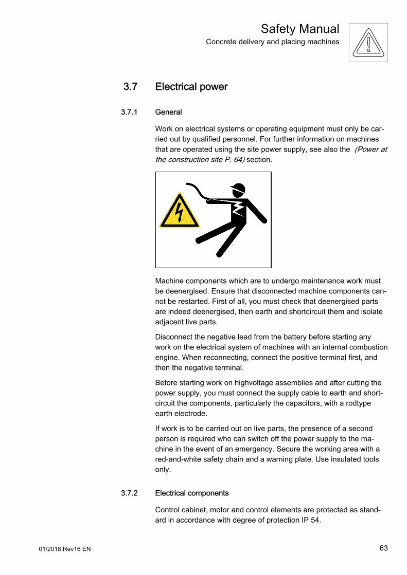
3.7 Electrical power
3.7.1 General
Work on electrical systems or operating equipment must only be car‐ried out by qualified personnel. For further information on machinesthat are operated using the site power supply, see also the (Power atthe construction site P. 64) section.
Machine components which are to undergo maintenance work mustbe deenergised. Ensure that disconnected machine components can‐not be restarted. First of all, you must check that deenergised partsare indeed deenergised, then earth and shortcircuit them and isolateadjacent live parts.
Disconnect the negative lead from the battery before starting anywork on the electrical system of machines with an internal combustionengine. When reconnecting, connect the positive terminal first, andthen the negative terminal.
Before starting work on highvoltage assemblies and after cutting thepower supply, you must connect the supply cable to earth and short‐circuit the components, particularly the capacitors, with a rodtypeearth electrode.
If work is to be carried out on live parts, the presence of a secondperson is required who can switch off the power supply to the ma‐chine in the event of an emergency. Secure the working area with ared-and-white safety chain and a warning plate. Use insulated toolsonly.
3.7.2 Electrical components
Control cabinet, motor and control elements are protected as stand‐ard in accordance with degree of protection IP 54.
Safety ManualConcrete delivery and placing machines
01/2018 Rev16 EN 63
IP 54 means:● Complete protection against contact with live components or inter‐
nal moving parts. Protection against damaging dust deposits.● Water spraying on the equipment from random directions must not
have a damaging effect.
Use only original fuses with the specified voltage rating. Bridging orthe use of fuses with too high a rating can irreparably damage theelectrical system. You must switch off the machine immediately if afault occurs in the power supply.
3.7.3 Power at the construction site
The power on the construction site must be supplied from a specialfeed point (construction site power distribution point). Machines withan electric motor must not be connected to the mains power supply.
Only trained and qualified personnel are permitted to work on electri‐cal systems with an operating voltage of more than 25 volts alternat‐ing voltage or 60 volts direct current. Only such qualified personnelmay install, connect, disconnect and open electrical control cabinets.
An electric shock (possibly with fatal consequences) may be the re‐sult of touching machines with electric motors or contact with otherelectrical cables if the electrical connection has not been made prop‐erly or the supply cable is damaged.
3.8 Hydraulic systems
3.8.1 General
Work on hydraulic systems must only be carried out by qualified per‐sonnel.
Always wear your personal protective equipment when carrying outwork on the hydraulic system. Escaping fluid is toxic and can pene‐trate the skin.
Safety ManualConcrete delivery and placing machines
64 01/2018 Rev16 EN
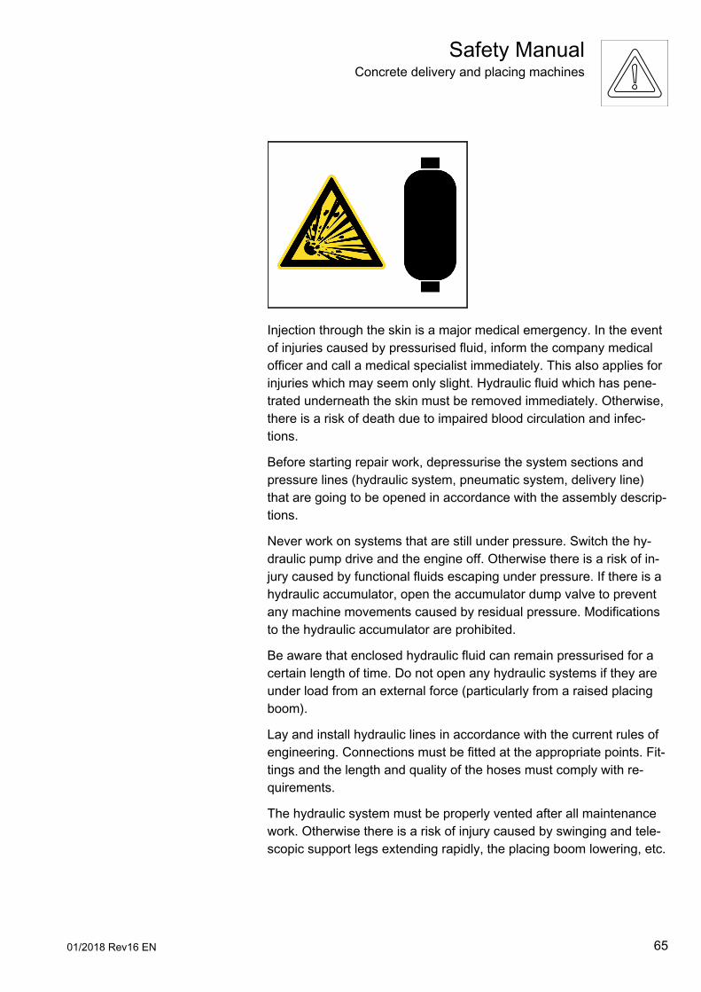
Injection through the skin is a major medical emergency. In the eventof injuries caused by pressurised fluid, inform the company medicalofficer and call a medical specialist immediately. This also applies forinjuries which may seem only slight. Hydraulic fluid which has pene‐trated underneath the skin must be removed immediately. Otherwise,there is a risk of death due to impaired blood circulation and infec‐tions.
Before starting repair work, depressurise the system sections andpressure lines (hydraulic system, pneumatic system, delivery line)that are going to be opened in accordance with the assembly descrip‐tions.
Never work on systems that are still under pressure. Switch the hy‐draulic pump drive and the engine off. Otherwise there is a risk of in‐jury caused by functional fluids escaping under pressure. If there is ahydraulic accumulator, open the accumulator dump valve to preventany machine movements caused by residual pressure. Modificationsto the hydraulic accumulator are prohibited.
Be aware that enclosed hydraulic fluid can remain pressurised for acertain length of time. Do not open any hydraulic systems if they areunder load from an external force (particularly from a raised placingboom).
Lay and install hydraulic lines in accordance with the current rules ofengineering. Connections must be fitted at the appropriate points. Fit‐tings and the length and quality of the hoses must comply with re‐quirements.
The hydraulic system must be properly vented after all maintenancework. Otherwise there is a risk of injury caused by swinging and tele‐scopic support legs extending rapidly, the placing boom lowering, etc.
Safety ManualConcrete delivery and placing machines
01/2018 Rev16 EN 65
Open vent valves very carefully until hydraulic fluid starts to escape.You should on no account open vent valves further than necessary orgo so far as to remove them.
Damaged hydraulic lines must be replaced rather than repaired. Youmust replace damaged or saturated hydraulic hoses immediately. Hy‐draulic fluid spray escaping under pressure can cause injuries andfires.
3.8.2 Replacing hydraulic hoses
During retesting, hydraulic hoses must be checked by a subject ex‐pert for external damage. The retest must be recorded in the checkbook. The operator must have hydraulic hoses replaced if they showsigns of external damage.
3.9 Noise emissions
The place of work in normal operation is with the remote control. Forthis reason, it is not possible to specify a particular place of work forthe machine operator. Take the values for the sound pressure leveland sound power level from the machine Operating Instructions.
Wear suitable personal protective equipment in the vicinity of the ma‐chine.
As the operator, you must instruct your personnel to always weartheir personal hearing protectors. You are responsible for ensuringthat your personnel comply with this regulation.
All soundproofing equipment must be fitted and in perfect condition.All soundproofing equipment must be closed during operation. A highsound level can cause permanent hearing damage.
3.10 Exhaust fumes
Vehicle exhaust gases contain constituents that can be deadly or car‐cinogenic. Operate internal combustion engines and fuel-operatedheating systems only in adequately ventilated premises. Before start‐ing up the engine in enclosed spaces, make sure that there is ade‐quate ventilation and direct the exhaust gases away from the place ofwork.
Safety ManualConcrete delivery and placing machines
66 01/2018 Rev16 EN
Wear personal protective clothing and equipment for all work in whichexhaust gases or particles of building material can enter the bodythrough the respiratory passages. Comply with the information issuedby the manufacturer of the building material.
3.11 Functional fluids
When handling oils, greases and other functional fluids, observe thesafety regulations applicable to the product concerned (see the safetydata sheet).
Oils, fuel and other functional fluids may be hazardous to health uponcontact with the skin, etc. You must therefore always wear personalprotective clothing and equipment when you are handling toxic, caus‐tic or other functional fluids that are hazardous to health and alwaystake note of the manufacturer’s information.
Take care when handling toxic and caustic functional fluids (brake flu‐id, battery acid, water glass, concrete set accelerating admixtures, ce‐ment, etc.). Building materials containing cement have a highly alka‐line effect when they react with water (and also with perspiration). Ad‐mixtures are toxic and caustic.
Cleaning agents, concrete release agents, preserving agents etc. pro‐pelled by compressed air can cause very serious damage to the res‐piratory tract if a respiratory protection mask is not worn. Spray mistenters the lungs very easily.
Frequent injuries are eye injuries caused by concrete spatter, waterglass or other chemical substances.
Take care when handling hot functional fluids and consumables (riskof burning or scalding).
Safety ManualConcrete delivery and placing machines
01/2018 Rev16 EN 67
Have used operating equipment and functional fluids such as filters,batteries, oil, brake fluid, etc. disposed of properly. Used cleaningrags should also be disposed of properly.
3.12 Disposal of the machine
To dispose of the machine, you must proceed in accordance with allpoints in the disposal regulations which apply in your country.
During the disposal operation, you must observe the following in par‐ticular:● Remove the functional fluids, particularly hydraulic fluids, engine
oils, fuel, brake fluid, concrete admixtures, any environmentallyhazardous functional fluids or functional fluids which are hazard‐ous in any other way, and dispose of these correctly.
● Remove the operating equipment, particularly the hydraulic fluidreservoir, hydraulic cylinder, hydraulic fluid radiator, hydraulic linesand hoses and other components which may contain residual func‐tional fluids, and dispose of these correctly.
● Remove the steel structure and dispose of it correctly, e.g. by recy‐cling.
● Dispose of the truck or the drive unit correctly.
Safety ManualConcrete delivery and placing machines
68 01/2018 Rev16 EN
IndexIn this chapter, you will find the most important keywords and the number(s) of the page(s) on which theyappear. This index of key words is in alphabetical order.
AAccessories and attachments P. 23
After Sales Service personnel P. 13
Arm assembly P. 11
BBase structure P. 11
Before working with the machine P. 31
CChanges to the machine P. 23
Checking that the machine is ready for operation P. 31
Cleaning P. 51
Cleaning agents P. 52
Cleaning with compressed air P. 53
Clearances P. 32
Clearance to delivery lines P. 48
Climbing the placing boom P. 23
Concrete pump P. 11
Concreting in cold weather P. 46
Connecting drills P. 45
Constant observation of the machine P. 51
Continuation delivery lines P. 48
Corner bearing loads P. 38
DDanger due to high voltage P. 31
Danger zone P. 17
Definition of terms P. 11
Delivery line systems P. 12, 18, 46
Designated use P. 18
Devices for shutting off, diverting and cleaning P. 49
Discharge voltage pattern P. 32
Disposal of the machine P. 68
Driving P. 39
EEarthing in the event of electrostatic charging P. 34
Earthing on construction sites with special equipment P. 34
Electrical components P. 63
Electrical power P. 63
End hose P. 12, 18, 43
Exclusion of liability P. 24
Exhaust fumes P. 66
Extending the placing boom and end hose P. 21
Extending the reach P. 21
FForeword P. 7
Functional fluids P. 67
GGeneral P. 51, 63, 64
Guiding the end hose ergonomically P. 44
Safety ManualConcrete delivery and placing machines
01/2018 Rev16 EN 69
HHighpressure delivery P. 23
High-voltage lines P. 31
Highvoltage warning devices P. 33
Hopper P. 18
Hoseman P. 12
Hydraulic systems P. 64
IImpermissible end hose P. 22
Impermissible working area P. 17, 22
Improper use P. 20
Inspection intervals for retesting P. 19
LLeak tightness and blockages P. 47
Lifting loads P. 21
Lifting machines and components P. 35
Loading P. 41
Loading and transporting P. 35
MMachine P. 11, 18
Machine operator P. 12
Maintenance P. 13
Maintenance and special work P. 57
Manufacturer P. 12
Mobile machines P. 14, 36
Moving machine components and hot surfaces P. 50
NNoise emissions P. 66
OOpening delivery lines P. 48
Operating Instructions P. 25
Operating Instructions, operating procedures and otherregulations P. 25
Operating procedures P. 26
Operator P. 12
Other regulations P. 27
PPersonal protective equipment P. 27
Personnel P. 24
Place of work P. 16, 49
Place of work, working area, danger zone P. 14
Place of work – hoseman P. 16
Place of work – machine operator P. 16
Place of work – truck mixer driver P. 16
Placing boom P. 11, 17
Placing booms P. 42
Post-cleaning procedure P. 55
Power at the construction site P. 64
Procedure in storms P. 45
Procedure in the event of a flash over P. 33
Protection against water P. 54
Protective and safety equipment P. 62
Pumping operations P. 49
QQualifications P. 25
Qualified personnel P. 13
RRemote control P. 50
Safety ManualConcrete delivery and placing machines
70 01/2018 Rev16 EN
Removing obstacles P. 21
Rendering the machine ready for operation P. 31
Replacing hydraulic hoses P. 66
Requirements P. 24
Requirements for special work P. 59
Responsibility of the machine operator P. 25
Retesting (safety inspection) P. 19
SSafety P. 49
Safetyrelevant components P. 62
Securing delivery lines P. 46
Securing the delivery lines P. 48
Setting up and working with the machine P. 29
Setup site P. 35, 36
Signaller and other auxiliary personnel P. 13
Software P. 62
Stationary machines P. 14, 35
Stationary placing booms P. 35
Subject expert P. 13
Suitable delivery lines P. 46
Supporting ground P. 37
Support legs and support feet P. 17
Supports P. 38
TTerms, definitions, requirements P. 9
Towing P. 41
Transporting goods P. 20
Truck mixer P. 12, 51
Truck mixer driver P. 13
UUnfold placing boom P. 42
WWelding P. 60
Working area P. 16
Working on the placing boom P. 61
Safety ManualConcrete delivery and placing machines
01/2018 Rev16 EN 71

72 01/2018 Rev16 EN


Related Documents


