Statics Chapter II Fall 2015 Exercises Corresponding to Sections 2.1, 2.2, and 2.3 2–3 Determine the magnitude of the resultant force F R = F 1 + F 2 and its direction, measured counterclockwise from the positive x axis. 2–7 Resolve the force F 1 into components acting along the u and v axes and determine the magnitudes of the components. 2–8 Resolve the force F 2 into components acting along the u and v axes and determine the magnitudes of the components. 2–20 Determine the design angle ϕ ( 0 o ≤ ϕ ≤ 90 o ) between struts AB and AC so that the 400-lb horizontal force has a component of 600 lb which acts up to the left, in the same direction as from B towards A. Take θ = 30°. 2–31 If the resultant force of the two tugboats is required to be directed towards the positive x axis, and F B is to be a minimum, determine the magnitude of F R and F B and the angle θ.

Welcome message from author
This document is posted to help you gain knowledge. Please leave a comment to let me know what you think about it! Share it to your friends and learn new things together.
Transcript

Statics Chapter II Fall 2015 Exercises Corresponding to Sections 2.1, 2.2, and 2.3
2–3 Determine the magnitude of the resultant force FR = F1 + F2 and its direction, measured counterclockwise from the positive x axis.
2–7 Resolve the force F1 into components acting along the u and v axes and determine the magnitudes of the components. 2–8 Resolve the force F2 into components acting along the u and v axes and determine the magnitudes of the components.
2–20 Determine the design angle ϕ ( 0o ≤ ϕ ≤ 90o) between struts AB and AC so that the 400-lb horizontal force has a component of 600 lb which acts up to the left, in the same direction as from B towards A. Take θ = 30°.
2–31 If the resultant force of the two tugboats is required to be directed towards the positive x axis, and FB is to be a minimum, determine the magnitude of FR and FB and the angle θ.
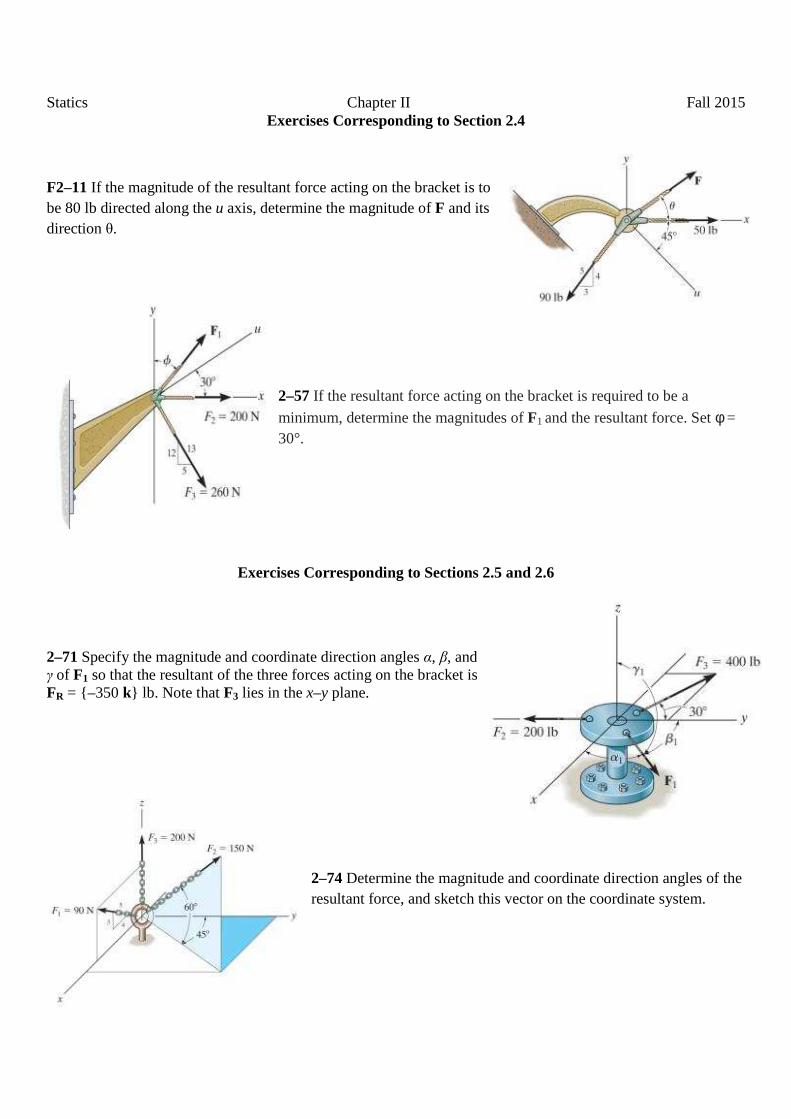
Statics Chapter II Fall 2015 Exercises Corresponding to Section 2.4
F2–11 If the magnitude of the resultant force acting on the bracket is to be 80 lb directed along the u axis, determine the magnitude of F and its direction θ.
2–57 If the resultant force acting on the bracket is required to be a
minimum, determine the magnitudes of F1 and the resultant force. Set φ = 30°.
Exercises Corresponding to Sections 2.5 and 2.6
2–71 Specify the magnitude and coordinate direction angles α, β, and γ of F1 so that the resultant of the three forces acting on the bracket is FR = {–350 k} lb. Note that F3 lies in the x–y plane.
2–74 Determine the magnitude and coordinate direction angles of the resultant force, and sketch this vector on the coordinate system.

Statics Chapter II Fall 2015 Exercises Corresponding to Sections 2.7 and 2.8
2–92 Express each of the forces in Cartesian vector form and determine the magnitude and coordinate direction angles of the resultant force.
2–98 The force F has a magnitude of 80 lb and acts at the midpoint C of the thin rod. Express the force as a Cartesian vector.
2–87 (13th Ed.) Determine the lengths of wires AD, BD, and CD. The ring at D is midway between A and B.
Exercises Corresponding to Section 2.9
2–130 Determine the angles θ and φ made between the axes OA of the flag pole and AB and AC, respectively, of each cable.

Statics Chapter II Fall 2015
2–126 Determine the magnitude of the projected component of the 100-lb force acting along the axis BC of the pipe and perpendicular to it.
2–122 Determine the angle θ between the cables AB and AC.
2–124 Determine the magnitude of the projected component of the force F = {400i – 200j + 500k} N acting along the cable CA and perpendicular to it.

Statics Chapter III Fall 2015
Exercises Corresponding to Sections 3.1, 3.2, 3.3, 8.1, and 8.2
3–7 The man attempts to pull down the tree using the cable and small pulley arrangement shown. If the tension in AB is 60 lb, determine the tension in cable CAD and the angle θ which the cable makes at the pulley.
3–22 The springs BA and BC each have a stiffness of 500 N/m and an unstretched length of 3 m. Determine the horizontal force F applied to the cord which is attached to the small ring B that the displacement of the ring from the wall is d = 1.5 m.
8–31 Two blocks A and B have a weight of 10 lb and 6 lb, respectively. They are resting on the incline for which the coefficients of static friction are µA = 0.15 and µB = 0,25. Determine the angle θ which will cause motion of one of the blocks. What is the friction force under each of the blocks when this occurs? The spring has a stiffness of k = 2 lb/ft and is originally unstretched.
8–39 (13th Ed.) Determine the smallest force the man must exert on the rope in order to move the 80-kg crate. Also, what is the angle θ at this moment? The coefficient of static friction between the crate and the floor is µs = 0.3.

Statics Chapter III Fall 2015
Exercises Corresponding to Section 3.4
3–45 If the bucket and its contents have a total weight of 20 lb, determine the force in the supporting cables DA, DB, and DC.
3–63 The crate has a mass of 130 kg. Determine the tension developed in each cable for equilibrium.
3–66 Determine the tension developed in cables AB, AC, and AD required for equilibrium of the 300-lb crate.

Statics Chapter IV Fall 2015
Exercises Corresponding to Section 4.1
4–5 Determine the moment about point B of each of the three forces acting on the beam.
4–11 The towline exerts a force of P = 6 kN at the end of the 8-m-long crane boom. If θ = 30o, determine the placement x of the hook at B so that this force creates a maximum moment about point O. What is this moment? 4–12 The towline exerts a force of P = 6 kN at the end of the 8-m-long crane boom. If x = 10 m, determine the position θ of the boom so that this force creates a maximum moment about point O. What is this moment?
Exercises Corresponding to Sections 4.2, 4.3, and 4.4
4–33 The pipe assembly is subjected to the force of F = {600i + 800j – 500k} N. Determine the moment of this force about point B.
4–35 Determine the smallest force F that must be applied along the rope in order to cause the curved rod, which has a radius of 4 m, to fail at the support A. This requires a moment of M = 1500 N•m to be developed at A.

Statics Chapter IV Fall 2015
4–48 Force F acts perpendicular to the inclined plane. Determine the moment produced by F about point A. Express the result as a Cartesian vector.
Exercises Corresponding to Section 4.5
4–57 Determine the moment of the force F about an axis extending between A and C. Express the result as a Cartesian vector.
4–63 Determine the magnitude of the moment of the force F = {50i - 20j - 80k} N about the base line CA of the tripod.

Statics Chapter IV Fall 2015
4–60 The A-frame is being hoisted into an upright position by the vertical force of F = 80 lb. Determine the moment of this force about the y axis when the frame is in the position shown.
Exercises Corresponding to Section 4.6
4–71 Two couples act on the beam. Determine the magnitude of F so that the resultant couple moment is 450 lb•ft, counterclockwise. Where on the beam does the resultant couple moment act?
4–72 Determine the magnitude of the couple force F so that the resultant couple moment on the crank is zero.
4–91 If the couple moment acting on the pipe has a magnitude of 300 N•m determine the magnitude F of the forces applied to the wrenches.
Statics Chapter IV Fall 2015
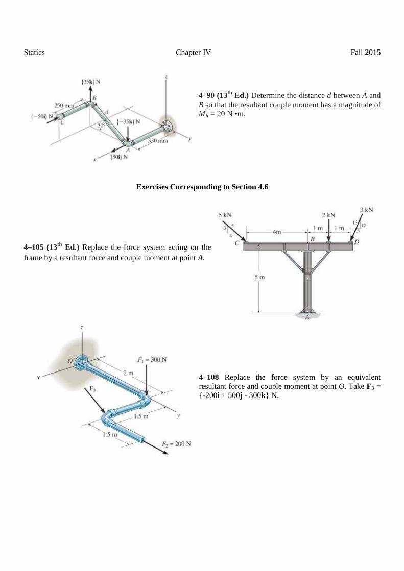
4–90 (13th Ed.) Determine the distance d between A and B so that the resultant couple moment has a magnitude of MR = 20 N •m.
Exercises Corresponding to Section 4.6
4–105 (13th Ed.) Replace the force system acting on the frame by a resultant force and couple moment at point A.
4–108 Replace the force system by an equivalent resultant force and couple moment at point O. Take F3 = {-200i + 500j - 300k} N.

Statics Chapter V Fall 2015
Exercises Corresponding to Section 9.1
9–17 Locate the centroid (x, y) of the area.
9–28 (13th Ed.) Locate the centroid (x, y) of the area.
9–5 Determine the distance x, y to the center of gravity of the homogeneous rod.
9–40 Locate the y–centroid of the paraboloid.

Statics Chapter V Fall 2015
9–43 Locate the centroid of the quarter–cone.
Exercises Corresponding to Section 9.2
F9–7 Locate the centroid (x, y, z) of the wire bent in the shape shown.
9–65 Determine the location (x, y) of the centroid C of the area.
Problem Centroids 1. Locate the centroid (x, y) of the composite area.

Statics Chapter V Fall 2015
9–85 Determine the distance z to the centroid of the shape which consists of a cone with a hole of height h = 50 mm bored into its base.
9–81 The assembly is made from a steel hemisphere, ρst = 7.80 Mg/m3, and an aluminum cylinder, ρal = 2.70 Mg/m3. Determine the center of mass of the assembly if the height of the cylinder is h = 200 mm.
Exercises Corresponding to Section 4.9
F4–37 Determine the resultant force and specify where it acts on the beam measured from A.

Statics Chapter V Fall 2015
4–144 The distribution of soil loading on the bottom of a building slab is shown. Replace this loading by an equivalent resultant force and specify its location, measured from point O.
4–155 Replace the distributed loading by an equivalent resultant force and specify where its line of action intersects a vertical line along member BC, measured from C.

Statics Chapter VI Fall 2015
Exercises Corresponding to Sections 5.1, 5.2, 5.3, and 5.4
F5–5 The 25 kg bar has its center of mass at G. If it is supported by a smooth peg at C, a roller at A, and a cord AB determine the reaction at these supports.
5–12 Determine the horizontal and vertical components of reaction at the pin A and the reaction of the rocker B on the beam.
5–15 Determine the reactions at the supports.

Statics Chapter VI Fall 2015
5–25 Determine the reactions on the bent rod which is supported by a smooth surface at B and by a collar at A, which is fixed to the rod and is free to slide over the fixed inclined rod.
5–27 Determine the reactions acting on the smooth uniform bar, which has a mass of 20 kg.
5–45 The man uses the hand truck to move material up the step. If the truck and its contents have a mass of 50 kg with center of gravity at G, determine the normal reaction on both wheels and the magnitude and direction of the minimum force required at the grip B needed to lift the load.

Statics Chapter VI Fall 2015
5–36 The beam of negligible weight is supported horizontally by two springs. If the beam is horizontal and the springs are unstretched when the load is removed, determine the angle of tilt of the beam when the load is applied.
8–24 The uniform thin pole has a weight of 30 lb and a length of 26 ft. If it is placed against the smooth wall and on the rough floor in the position d = 10 ft, will it remain in this position when it is released? The coefficient of static friction is µs = 0.3.
8–32 Determine the smallest force P that must be applied in order to cause the 150-lb uniform crate to move. The coefficient of static friction between the crate and the floor is µs = 0.5.

Statics Chapter VI Fall 2015
Exercises Corresponding to Sections 5.1, 5.2, 5.3, and 5.4 5–82 The sign has a mass of 100 kg with center of mass at G. Determine the x, y, z components of reaction at the ball-and socket joint A and the tension in wires BC and BD.
5–82 (13th Ed.) Determine the tensions in the cables and the components of reaction acting on the smooth collar at A necessary to hold the 50-lb sign in equilibrium. The center of gravity for the sign is at G.
RB–2. Determine the tensions TAE and TGF in the two supporting cables resulting from the 1.2–kN tension in cable CD. Assume the absence of any resisting moments on the base of the pole at O about the x– and y–axes, but not about z–axis. Use vector approach.

Statics Chapter VII Fall 2015
Exercises Corresponding to Sections 6.1, 6.2, and 6.3
6–8 Determine the force in each member of the truss, and state if the members are in tension or compression.
6–17 If the maximum force that any member can support is 8 kN in tension and 6 kN in compression, determine the maximum force P that can be supported at joint D.
Exercises Corresponding to Section 6.4 R6–4 Determine the force in members GF and FB, and BC of the Fink truss and state if the members are in tension or compression.
6–46 (13th Ed.) Determine the force in members CD and CM of the Baltimore bridge truss and state if the members are in tension or compression. Also, indicate all zero-force members.

Statics Chapter VII Fall 2015
6–40 Determine the force in members CD, CF, and CG and state if these members are in tension or compression.
Exercises Corresponding to Section 6.6 6–61 Determine the force P required to hold the 100-lb weight in equilibrium.
6–69 Determine the reactions at supports A and B.
6–70 Determine the horizontal and vertical components of force at pins B and C. The suspended cylinder has a mass of 75 kg.

Statics Chapter VII Fall 2015
6–72 Determine the resultant force at pins A, B, and C on the three-member frame.
6–76 Determine the horizontal and vertical components of force which the pins at A and B exert on the frame.
6–77 The two-member structure is connected at C by a pin, which is fixed to BDE and passes through the smooth slot in member AC. Determine the horizontal and vertical components of reaction at the supports.
Statics Chapter VII Fall 2015
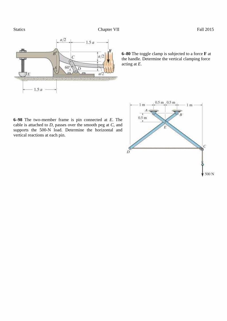
6–80 The toggle clamp is subjected to a force F at the handle. Determine the vertical clamping force acting at E.
6–98 The two-member frame is pin connected at E. The cable is attached to D, passes over the smooth peg at C, and supports the 500-N load. Determine the horizontal and vertical reactions at each pin.

Statics Chapter VIII Fall 2015
Exercises Corresponding to Section 7.1
7–18 Determine the internal normal force, shear force, and the moment at points C and D.
7–22 Determine the internal normal force, shear force, and moment at points D and E in the overhang beam. Point D is located just to the left of the roller support at B, where the couple moment acts.
Exercises Corresponding to Section 7.2
7–46 Draw the shear and moment diagrams for the beam (a) in terms of the parameters shown; (b) set P = 800 lb, a = 5 ft, L = 12 ft.
F7–8 Determine the shear and moment as a function of x, then draw the shear and moment diagrams.
Statics Chapter VIII Fall 2015
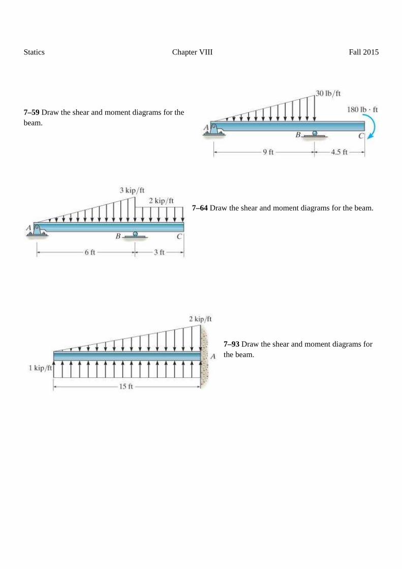
7–59 Draw the shear and moment diagrams for the beam.
7–64 Draw the shear and moment diagrams for the beam.
7–93 Draw the shear and moment diagrams for the beam.

Statics Chapter IX Fall 2015
Exercises Corresponding to Sections 10.1 and 10.2 10–21 Determine the moment of inertia for the shaded area about the x axis. 10–22 Determine the moment of inertia for the shaded area about the y axis.
10–23 Determine the moment of inertia for the shaded area about the x axis.
10–24 Determine the moment of inertia for the shaded area about the y axis.
Exercises Corresponding to Section 10.4 10–25 Determine the moment of inertia of the composite area about the x axis.

Statics Chapter IX Fall 2015
10–47 Determine the moment of inertia for the shaded area about the y axis.
Related Documents