Statics and Dynamics with Background Mathematics A. P. Roberts

Welcome message from author
This document is posted to help you gain knowledge. Please leave a comment to let me know what you think about it! Share it to your friends and learn new things together.
Transcript

Statics and Dynamicswith Background Mathematics
A. P. Roberts

published by the press syndicate of the university of cambridgeThe Pitt Building, Trumpington Street, Cambridge, United Kingdom
cambridge university pressThe Edinburgh Building, Cambridge CB2 2RU, UK40 West 20th Street, New York, NY 10011-4211, USA477 Williamstown Road, Port Melbourne, VIC 3207, AustraliaRuiz de Alarcon 13, 28014 Madrid, SpainDock House, The Waterfront, Cape Town 8001, South Africa
http://www.cambridge.org
C© Cambridge University Press 2003
This book is in copyright. Subject to statutory exceptionand to the provisions of relevant collective licensing agreements,no reproduction of any part may take place withoutthe written permission of Cambridge University Press.
First published 2003
Printed in the United Kingdom at the University Press, Cambridge
TypefacesTimes 10.5/14 pt and Helvetica SystemLATEX2ε [tb]
A catalogue record for this book is available from the British Library
Library of Congress Cataloguing in Publication data
Roberts, A. P.Statics and dynamics with background mathematics / A. P. Roberts.
p. cm.Includes bibliographical references and index.ISBN 0 521 81766 8 – ISBN 0 521 52087 8 (pbk.)1. Statics. 2. Dynamics. I. Title.QA821 .R64 2003531′.12 – dc21 2002073607
ISBN 0 521 81766 8 hardbackISBN 0 521 52087 8 paperback

Contents
Preface pagexiii
Part I Statics 1
1 Forces 31.1 Force 31.2 Forces of contact 41.3 Mysterious forces 51.4 Quantitative definition of force 61.5 Point of application 71.6 Line of action 71.7 Equilibrium of two forces 81.8 Parallelogram of forces (vector addition) 91.9 Resultant of three coplanar forces acting at a point 121.10 Generalizations for forces acting at a point 131.11 More exercises 151.12 Answers to exercises 16
2 Moments 252.1 Moment of force 252.2 Three or more non-parallel non-concurrent coplanar forces 272.3 Parallel forces 282.4 Couples 312.5 Equations of equilibrium of coplanar forces 332.6 Applications 352.7 Answers to exercises 37
3 Centre of gravity 453.1 Coplanar parallel forces 453.2 Non-coplanar parallel forces 473.3 Finding c.g. positions of uniform plane laminas without using calculus 493.4 Using calculus to find c.g. positions of uniform plane laminas 51
vii

viii Contents
3.5 Centre of gravity positions of uniform solid bodies of revolution 533.6 Answers to exercises 55
4 Distributed forces 594.1 Distributed loads 594.2 Hydrostatics 614.3 Buoyancy 634.4 Centre of pressure on a plane surface 644.5 Answers to exercises 65
5 Trusses 705.1 Method of sections 705.2 Method of joints 725.3 Bow’s notation 765.4 Answers to exercises 81
6 Beams 856.1 Shearing force and bending moment 856.2 Uniformly distributed beam loading 876.3 Using calculus 906.4 Answers to exercises 92
7 Friction 987.1 Force of friction 987.2 Sliding or toppling? 997.3 Direction of minimum pull 1017.4 Ladder leaning against a wall 1027.5 Motor vehicle clutch 1037.6 Capstan 1047.7 Answers to exercises 105
8 Non-coplanar forces and couples 1098.1 Coplanar force and couple 1098.2 Effect of two non-coplanar couples 1118.3 The wrench 1148.4 Resultant of a system of forces andcouples 1168.5 Equations of equilibrium 1178.6 Answers to exercises 119
9 Virtual work 1239.1 Work done by a force 1239.2 Work done by a couple 1239.3 Virtual work for a single body 1249.4 Virtual work for a system of bodies 1259.5 Stability of equilibrium 1309.6 Answers to exercises 134

ix Contents
Part II Dynamics 139
10 Kinematics of a point 14110.1 Rectilinear motion 14110.2 Simple harmonic motion 14210.3 Circular motion 14410.4 Velocity vectors 14510.5 Relative velocity 14610.6 Motion along a curved path 14710.7 Answers to exercises 150
11 Kinetics of a particle 15411.1 Newton’s laws of motion 15411.2 Sliding down a plane 15511.3 Traction and braking 15711.4 Simple harmonic motion 15811.5 Uniform circular motion 16011.6 Non-uniform circular motion 16111.7 Projectiles 16211.8 Motion of connected weights 16511.9 Answers to exercises 167
12 Plane motion of a rigid body 17312.1 Introduction 17312.2 Moment 17312.3 Instantaneous centre of rotation 17412.4 Angular velocity 17612.5 Centre of gravity 17812.6 Acceleration of the centre of gravity 17912.7 General dynamic equations 18012.8 Moments of inertia 18212.9 Perpendicular axis theorem 18412.10 Rotation about a fixed axis 18512.11 General plane motion 18812.12 More exercises 19112.13 Answers to exercises 194
13 Impulse and momentum 20713.1 Definition of impulse and simple applications 20713.2 Pressure of a water jet 20913.3 Elastic collisions 21013.4 Moments of impulse and momentum 21113.5 Centre of percussion 21413.6 Conservation of moment of momentum 21513.7 Impacts 21613.8 Answers to exercises 217

x Contents
14 Work, power and energy 22114.1 Work done by force on a particle 22114.2 Conservation of energy 22314.3 Spring energy 22414.4 Power 22514.5 Kinetic energy of translation and rotation 22514.6 Energy conservation with both translation and rotation 22614.7 Energy and moment of momentum 22714.8 Answers to exercises 229
Part III Problems 233
15 Statics 235
16 Dynamics 263
Part IV Background mathematics 281
17 Algebra 28317.1 Indices 28317.2 Logarithm 28317.3 Polynomials 28417.4 Partial fractions 28517.5 Sequences and series 28717.6 Binomial theorem 290
18 Trigonometry 29218.1 Introduction 29218.2 Trigonometrical ratios to remember 29418.3 Radian measure 29518.4 Compound angles 29618.5 Solution of trigonometrical equations: inverse
trigonometrical functions 29818.6 Sine and cosine rules 300
19 Calculus 30119.1 Differential calculus 30119.2 Differentiation from first principles 30219.3 More derivative formulae 30419.4 Complex numbers 30819.5 Integral calculus 31019.6 The definite integral 311

xi Contents
19.7 Methods of integration 31519.8 Numerical integration 32019.9 Exponential functionex and natural logarithm lnx 32319.10 Some more integrals using partial fractions and integration by parts 32619.11 Taylor, Maclaurin and exponential series 327
20 Coordinate geometry 32920.1 Introduction 32920.2 Straight line 33120.3 Circle 33220.4 Conic sections 33520.5 Parabola 33520.6 Ellipse 33820.7 Hyperbola 33920.8 Three-dimensional coordinate geometry 34120.9 Equations for a straight line 34320.10 The plane 34420.11 Cylindrical and spherical coordinates 346
21 Vector algebra 34921.1 Vectors 34921.2 Straight line and plane 35121.3 Scalar product 35421.4 Vector product 356
22 Two more topics 35922.1 A simple differential equation 35922.2 Hyperbolic sines and cosines 360
Appendix: answers to problems in Part III 361Index 365

1 Forces
1.1 Force
In the study of statics we are concerned with two fundamental quantities: length ordistance, which requires no explanation, and force. The quantity length can be seenwith the eye but with force, the only thing that is ever seen is its effect. We can seea spring being stretched or a rubber ball being squashed but what is seen is only theeffect of a force being applied and not the force itself. With a rigid body there is nodistortion due to the force and in statics it does not move either. Hence, there is novisual indication of forces being applied.We detect a force being applied to our human body by our sense of touch or feel.
Again, it is not the force itself but its effect which is felt – we feel the movement of ourstomachs when we go over a humpback bridge in a fast car; we feel that the soles ofour feet are squashed slightly when we stand.We have now encountered one of the fundamental conceptual difficulties in the study
of mechanics. Force cannot be seen or measured directly but must always be imagined.Generally the existence of some force requires little imagination but to imagine all thedifferent forces which exist in a given situationmay not be too easy. Furthermore, in or-der to perform any analysis, the forcesmust be defined precisely inmathematical terms.For the moment we shall content ourselves with a qualitative definition of force. ‘A
force is that quantity which tries to move the object on which it acts.’ This qualitativedefinition will suffice for statical problems in which the object does not move butwe shall have to give it further consideration when we study the subject of dynamics.If the object does not move, the force must be opposed and balanced by another force.If we push with our hand against a wall, we know that we are exerting a force; wealso know that the wall would be pushed over if it were not so strong. By saying thatthe wall is strong we mean that the wall itself can produce a force to balance the oneapplied by us.
EXERCISE 1Note down a few different forces and state whether, and if so how, they might be observed.
3

4 Forces
1.2 Forces of contact
Before giving a precise mathematical description of force, we shall discuss two generalcategories. We shall start with the type which is more easily imagined; this is that dueto contact between one object and another.In the example of pushing against a wall with one’s hand, the wall and hand are in
contact, a force is exerted by the hand on the wall and this is opposed by another forcefrom the wall to the hand. In the same way, when we are standing on the ground wecan feel the force of the ground on our feet in opposition to the force due to our weighttransmitted through our feet to the ground. Sometimes we think of a force being a pullbut if we analyse the situation, the force of contact from one object to another is stilla push. For instance, suppose a rope is tied around an object so that the latter may bepulled along. When this happens, the force from the rope which moves the object is apush on the rear of the object.Another form of contact force is that which occurs when a moving object strikes
another one. Any player of ball games will be familiar with this type of force. It onlyacts for a short time and is called an impulsive force. It is given special considerationin dynamics but it also occurs in statics in the following sense. When the surface of anobject is in contact with a gas, the gas exerts a pressure, that is a force spread over thesurface. The pressure is caused by the individual particles of the gas bouncing againstthe surface and exerting impulsive forces. The magnitude of each force is so small butthe frequency of occurrence is so high that the effect is that of a force continuouslydistributed over the whole surface.Forces of contact need not be exerted normal to the surface of contact. It is also
possible to exert what is called a tangential or frictional component of force. In this casethe force is applied obliquely to the surface;we can think of part being applied normally,i.e. perpendicular to the surface, and part tangentially. The maximum proportion of thetangential part whichmay be applied depends upon the nature of the surfaces in contact.Iceskaters knowhowsmall the tangential component canbeandmanufacturersofmotorcar tyres know how high.A fact which must be emphasized concerning contact forces is that the forces each
way are always equal and opposite, i.e. action and reaction are equal and opposite.When you push against the wall with your hand, the force from your hand on the wallis equal and opposite to the force from the wall against your hand. The rule is true forany pair of contact forces.
EXERCISE 2Note down some of the contact forces which you have experienced or which have been applied toobjects with which you have been concerned during the day. For each contact force, note the equaland opposite force which opposed it.

5 1.3 Mysterious forces
1.3 Mysterious forces
It is not too difficult to imagine the contact forces already described from our everydayexperience but what is it that prevents a solid object from bending, squashing or justfalling apart under the action of such forces?Mysterious forces of attraction act betweenthe separate molecules of the material binding them together in a particular way andresisting outside forces which try to disturb the pattern. Theseintermolecular forcesconstitute the strength of the material. Although we shall not be concerned with ithere, knowledge of the strength of materials is of great importance to engineers whendesigning buildings, machinery, etc.Another mysterious force which will concern us deeply is theforce of gravity. The
magnitude of the force of gravity acting on a particular object depends on the size andphysical nature of the object. In our study this force will remain constant and it willalways act vertically downwards, this being referred to as theweightof the object. Thisis sufficient for most earthbound problems but when studying artificial satellites andspace-craft it is necessary to consider the full properties of gravity.Gravity is a force of attraction between any two bodies. It needs no material for its
transmission nor is it impeded or changed in any way by material placed in betweenthe bodies in question. The magnitude of the force was given mathematical form by SirIsaac Newton and published in hisPhilosophiae Naturalis Principia Mathematicain1687. The force is proportional to the product of themasses of the two bodies divided bythe square of the distance between them. We shall say more about mass when studyingdynamics but it is a constant property of any body. The lawof gravitation, i.e. the inversesquare law, was deduced by correlating it with the elliptical motion of planets aboutthe sun as focus. Newton proved that such motion would be produced by the inversesquare law of attraction to the sun acting on each planet.Given that abodygeneratesanattractive forceproportional to itsmass, it is reasonable
that an inversesquare lawwith respect todistanceshouldapply.The forceacts in towardsthe body from all directions around. However, the force acts over a larger area as thedistance from the body increases. Since the effort is spread out over a larger area wecan expect the strength at any particular point in the area to decrease accordingly. Thuswe expect the magnitude of the force to be inversely proportional to the area of thesphere with the body at the centre and the point at which the force acts being on thesurface of the sphere. The area is proportional to the square of the radius of the sphere;hence the inverse square law follows.Magnetic and electrostatic forces are also important mysterious forces. However,
they will not be dicussed here since we shall not be concerned with them in this text.
EXERCISE 3Find the altitude at which the weight of a body is one per cent less than its weight at sea level. (Assumethat the radius of the earth from sea level is 6370 km.)

6 Forces
EXERCISE 4Find the percentage reduction in weight when the body is lifted from sea level to a height of 3 km.
1.4 Quantitative definition of force
In statics, force is that quantity which tries to move the object on which it acts. Themagnitude of a force is the measure of its strength. It is then necessary to define basicunits of measurement.In lifting different objects we are very familiar with the concept of weight,which
is the downward gravitational force on an object. It is tempting to use the weight of aparticular object as the unit of force.However, weight varieswith altitude (seeExercises3 and 4) and alsowith latitude. To avoid this, a dynamical unit of force has beenadopted.The basic SI unit (Syst`eme International d’Unit´es) is the newton (symbol N). It is the
force which would give a mass of one kilogramme (1 kg) an acceleration of one metreper second per second (1m/s2 or 1ms−2). The kilogramme is the mass of a particularpiece of platinum–iridium. Of course, once a standard has been set, other masses caneasily be evaluated by comparing relative weights. Incidentally, the mass of 1 kg isapproximately the mass of one cubic decimetre of distilled water at the temperature(3.98◦C) at which its density is maximum.If you are more familiar with the pound-force (lbf) as the unit of force, then1 lbf = 4.449 N or 1N= 0.2248 lbf.In quantifying a force, not only must its magnitude be given but also its direction of
application, i.e. the direction inwhich it tries tomove the object onwhich it acts. Havingboth magnitude and direction, force is avectorquantity. Sometimes it is convenient torepresent a force graphically by an arrow (see Figure 1.1) which points in a directioncorresponding to thedirectionof the forceandhasa lengthproportional to themagnitudeof the force.
EXERCISE 5Consider an aeroplane (see Figure 1.2) flying along at constant speed and height. Since there is noacceleration, forces should balance out in the same way that they do in statics. Draw vectors whichmight correspond to (a) the weight of the aeroplane, (b) the thrust from its enginesand (c) the forcefrom the surrounding air on the aeroplane which is a combination of lift and drag (lift/drag).
Figure 1.1. Force vector.

7 1.6 Line of action
Figure 1.2. Simple sketch of an aeroplane.
1.5 Point of application
In studying forces acting on a rigid body, it is necessary to know the points of the body towhich the forces are applied. For instance, consider a horizontal force applied to a stonewhich is resting on horizontal ground. If the force is strong enough the stone will move,but whether it moves by toppling or slipping depends on where the force is applied.Forces rarely act at a single point of a body. Usually the force is spread out over a
surface or volume. If the stone mentioned above is pushed with your hand, then theforce from your hand is spread out over the surface of contact between your hand andthe stone. The force from the ground which is acting on the stone is spread out over thesurface of contact with the ground. The gravitational force acting on the stone is spreadout over the whole volume of the stone. In order to perform the analysis in minutedetail it would be necessary to consider each small force acting on each small elementof area and on each small element of volume. However, since we are only consideringrigid bodies, we are not concernedwith internal stress. Thus we can replacemany smallforces by one large force. In our example, the small forces from the small elementsof area of contact of your hand are represented by a single large force acting on thestone. Similarly, we have a single large force acting from the ground. Also, for the smallgravitational forces acting on all the small elements of volume of the stone, we haveinstead a single force equal to the weight of the stone acting at a point in the stonewhich is called thecentre of gravity.The derivation of the points of action of these equivalent resultant forces will be
discussed later. For the time being we shall assume that the representation is valid sothat we can study the example of the stone as though there were only three forces actingon it, one from your hand, one from the ground and one from gravity.
EXERCISE 6Continue Exercise 5 by drawing in the three force vectors on a rough sketch of the aeroplane.
1.6 Line of action
In the answer to Exercise 6, it appears that the three resultant forces of weight, thrustand lift/drag all act at the same point. Of course this may not be so but it does not

8 Forces
matter provided the lines of action of the three resultant forces intersect at one point.For instance, this point need not coincide with the centre of gravity but it must be inthe same vertical line as the centre of gravity.Thus, with a rigid body the effect of a force is the same for any point of application
along its line of action. This property is referred to as theprinciple of transmissibility.If two non-parallel but coplanar forces act on a body, it is convenient to imagine themto be acting at the point of intersection of their lines of action.
EXERCISE 7Suppose that a smooth sphere is held on an inclined plane by a string which is fastened to a point onthe surface of the sphere at one end and to a point on the plane at the other end. Sketch the side viewand draw in the force vectors atthe points of intersection of their lines of action.
EXERCISE 8Do the same as in Exercise 7 for a ladder leaning against a wall, assuming that the lines of action ofthe three forces (weight and reactions from wall and ground) are concurrent.
Problems 1 and 2.
1.7 Equilibrium of two forces
A force tries to move its point of application and it will move it unless there is an equaland opposite counterbalancing force. When you push a wall with your hand, the wallwill move unless it is strong enough to produce an equal and opposite force on yourhand. If you are holding a dog with a lead, you will only remain stationary if you pullon the lead with the same amount of force as that exerted by the dog. By consideringsuch physical examples we can see that for two forces to balance each other, they mustbe equal in magnitude and opposite in direction.Yet another property is also required for the balance to exist. Supposewe have a large
wheel mounted on a vertical axle. If one person pushes the wheel tangentially alongthe rim on one side and another person pushes on the other side, the wheel will start tomove if the two pushes are equal in magnitude and opposite in direction. In fact twoforces only balance each other if not only are they equal in magnitude and opposite indirection but also have the same line of action.When you are holding the dog, the line ofthe lead is the line of action of both the force from your hand and the force from the dog.When the three conditions hold, we say that the two forces are inequilibrium. If a
rigid body is acted on by only two such forces, the body will not move and we saythat the body is in equilibrium. When a stone rests in equilibrium on the ground, theresultant contact force from the ground is equal, opposite and collinear to the resultantgravitational force acting on the stone.

9 1.8 Parallelogram of forces (vector addition)
EXERCISE 9Suppose that a rigid straight rod rests on its side on a smooth horizontal surface. Let two horizontalforces of equal magnitude be applied to the rod simultaneously, one at either end. Consider whatwill happen to the rod immediately after the forces have been applied for a few different situationsregarding the directions in which the separate forces are applied. Show that there will be only twopossible situations in which the rod will remain in equilibrium.
1.8 Parallelogram of forces (vector addition)
If two non-parallel forcesF1 andF2 act at a point A, they have a combined effectequivalent to a single forceR acting at A. The single forceR is called theresultantandit may be found as follows. LetF1 andF2 be represented in magnitude and directionby two sides of a parallelogram meeting at A. ThenR is represented in magnitude anddirection by the diagonal of the parallelogram from A, as shown in Figure 1.3. This isan empirical result referred to as the parallelogram law.The parallelogram law may be illustrated by the following experiment. Take three
different known weights of magnitudesW1,W2 andW3, and attachW1 andW2 to eitherend of a length of string. Drape the string over two smooth pegs set a distance apart atabout the same height. Then attachW3 with a small piece of string to a point A of theother string between the two pegs. Finally, allowW3 to drop gently and possibly movesideways until an equilibrium position is established (see Figure 1.4).Nowmeasure the angles to the horizontal made by the sections of string between the
two pegs and A. Make an accurate drawing of the strings which meet at A and mark offdistances proportional toW1 andW2 as shown in Figure 1.5. Since the pegs are smooth,
F1
F2
R
Figure 1.3. Parallelogram of forces.
Figure 1.4. String over two smooth pegs.
10 Forces
F1 W1
F3 W3
F2 W2
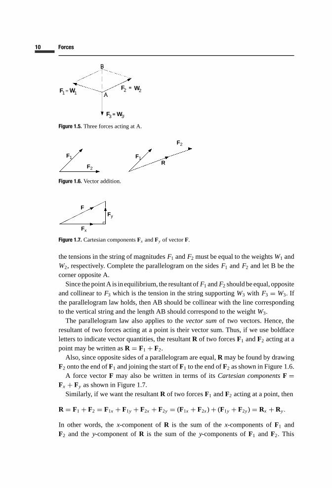
Figure 1.5. Three forces acting at A.
F1 F1
F2
F2
R
Figure 1.6. Vector addition.
Fy
Fx
F
Figure 1.7. Cartesian componentsFx andFy of vectorF.
the tensions in the string of magnitudesF1 andF2 must be equal to the weightsW1 andW2, respectively. Complete the parallelogram on the sidesF1 andF2 and let B be thecorner opposite A.Since thepointA is inequilibrium, the resultant ofF1 andF2 shouldbeequal, opposite
and collinear toF3 which is the tension in the string supportingW3 with F3 = W3. Ifthe parallelogram law holds, then AB should be collinear with the line correspondingto the vertical string and the length AB should correspond to the weightW3.The parallelogram law also applies to thevector sumof two vectors. Hence, the
resultant of two forces acting at a point is their vector sum. Thus, if we use boldfaceletters to indicate vector quantities, the resultantR of two forcesF1 andF2 acting at apoint may be written asR = F1 + F2.Also, since opposite sides of a parallelogram are equal,R may be found by drawing
F2 onto the end ofF1 and joining the start ofF1 to the end ofF2 as shown in Figure 1.6.A force vectorF may also be written in terms of itsCartesian componentsF =
Fx + Fy as shown in Figure 1.7.Similarly, if we want the resultantR of two forcesF1 andF2 acting at a point, then
R = F1 + F2 = F1x + F1y + F2x + F2y = (F1x + F2x)+ (F1y + F2y) = Rx + Ry.
In other words, thex-component ofR is the sum of thex-components ofF1 andF2 and they-component ofR is the sum of they-components ofF1 andF2. This

11 1.8 Parallelogram of forces (vector addition)
F1
Rx
RRy
F2
Figure 1.8. Addition of Cartesian components in vector addition.
Figure 1.9. Three elastic bands used to demonstrate the parallelogram law.
F1
F2
2
Figure 1.10. Two forcesF1 andF2 acting at a point A.
can be seen diagramatically by drawing in the Cartesian components as illustrated inFigure 1.8.
EXERCISE 10Use a piece of cotton thread to tie together three identical elastic bands. Having measured the un-stretched length of the bands, peg themout as indicated in Figure 1.9, so that each band is in a stretchedstate but not beyond the elastic limit. The points A, B and C represent the fixed positions of the pegsbut the point P takes up its equilibrium position pulled in three directions by the tensions in the bands.Use the fact that tension in each band is proportional to extension in order to verify the parallelogramlaw for the resultant of two forces acting at a point.
EXERCISE 11Calculate themagnitude and direction of the resultantR of the two forcesF1 andF2 acting at the pointA given the magnitudesF1 = 1N, F2 = 2N and directionsθ1 = 60◦, θ2 = 30◦ (see Figure 1.10).
Problems 3 and 4.

12 Forces
1.9 Resultant of three coplanar forces acting at a point
Consider the three forcesF1, F2 andF3 shown in Figure 1.11. The resultantR1 of F1
andF2 can be found by drawing the vectorF2 on the end ofF1 and joining the start ofF1 to the end ofF2. Then the final resultantR of R1 andF3, i.e. ofF1, F2 andF3, isfound by drawing the vectorF3 on the end ofR1 and joining the start ofR1 to the end ofF3. Having done this, we see that the intermediate step of insertingR1 may be omitted.Hence, the construction shown in Figure 1.11 is replaced by that of Figure 1.12. Theprocedure is simply to join the vectorsF1, F2 andF3 end-on-end; then the resultantRcorresponds to the vector joining the start ofF1 to the end ofF3.The resultant vectorR corresponds to the vector addition
R = F1 + F2 + F3.
In terms of Cartesian components:
Rx = F1x + F2x + F3x
and
Ry = F1y + F2y + F3y.
The three forcesF1, F2 andF3 will be in equilibrium if their resultantR is zero. Inthis case, joining the vectors end-on-end, the end ofF3 will coincide with the start ofF1. Thus we have the triangle of forces, which states that three coplanar forces actingat a point are in equilibrium if their vectors joined end-on-end correspond to the sidesof a triangle, as illustrated in Figure 1.13.
F1
F1 R1
R
F2
F2
F3
F3
Figure 1.11. Constructing the resultant of three coplanar forces acting at a point.
F1
F2
F3
R
Figure 1.12. The final constructionR = F1 + F2 + F3.
13 1.10 Generalizations for forces acting at a point
F1 F2
F3
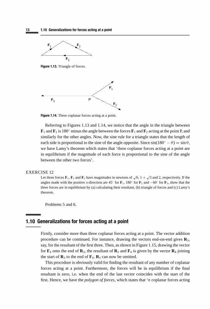
Figure 1.13. Triangle of forces.
F1
F2
F3
Figure 1.14. Three coplanar forces acting at a point.
Referring to Figures 1.13 and 1.14, we notice that the angle in the triangle betweenF1 andF2 is 180◦ minus the angle between the forcesF1 andF2 acting at the point P, andsimilarly for the other angles. Now, the sine rule for a triangle states that the length ofeach side is proportional to the sine of the angle opposite. Since sin(180◦ − θ) = sinθ ,we have Lamy’s theorem which states that ‘three coplanar forces acting at a point arein equilibrium if the magnitude of each force is proportional to the sine of the anglebetween the other two forces’.
EXERCISE 12Let three forcesF1, F2 andF3 have magnitudes in newtons of
√6,1+ √
3 and 2, respectively. If theangles made with the positivex-direction are 45◦ for F1, 180◦ for F2 and−60◦ for F3, show that thethree forces are in equilibrium by (a) calculating their resultant, (b) triangle of forces and (c) Lamy’stheorem.
Problems 5 and 6.
1.10 Generalizations for forces acting at a point
Firstly, consider more than three coplanar forces acting at a point. The vector additionprocedure can be continued. For instance, drawing the vectors end-on-end givesR3,say, for the resultant of the first three. Then, as shown in Figure 1.15, drawing the vectorfor F4 onto the end ofR3, the resultant ofR3 andF4 is given by the vectorR4 joiningthe start ofR3 to the end ofF4. R3 can now be omitted.This procedure is obviously valid for finding the resultant of any number of coplanar
forces acting at a point. Furthermore, the forces will be in equilibrium if the finalresultant is zero, i.e. when the end of the last vector coincides with the start of thefirst. Hence, we have thepolygon of forces, which states that ‘n coplanar forces acting

14 Forces
F1
F2
F3
R3
R4
F4
Figure 1.15. Constructing the resultant of four coplanar forces acting at a point.
at a point are in equilibrium if their vectors joined end-on-end complete ann-sidedpolygon’.Although it is not convenient for two-dimensional drawing, the basic concept can be
extended to finding the resultant of non-coplanar forces acting at a point. Any two of theforces are coplanar, so the resultantR2 of F1 andF2 is the vector sumR2 = F1 + F2.ThenR2 andF3 must be coplanar with resultantR3 = R2 + F3 = F1 + F2 + F3. Thus,if there aren forces, their resultant isRn = F1 + F2 + · · · + Fn.We have now moved from two-dimensional to three-dimensional space. Each vec-
tor has threeCartesian components, i.e. its x-, y- andz-components. The Cartesiancomponents ofRn are :
Rnx = F1x + F2x + · · · + Fnx
Rny = F1y + F2y + · · · + Fny
Rnz = F1z + F2z + · · · + Fnz
wherex, y andz signify the corresponding component in each case.As in the coplanar case, the forces will be in equilibrium if their resultantRn is zero,
i.e. Rnx = Rny = Rnz = 0.
EXERCISE 13Let four coplanar forcesF1, F2, F3 andF4 acting at a point have magnitudes in newtons of 2,
√6,
2 and√2, and directions relative to the positivex-axis of 150◦,45◦, −60◦ and−135◦, respectively.
Show that the four forces are in equilibrium by (a) calculating their resultant and (b) using a polygonof forces.
EXERCISE 14Find the resultant of three non-coplanar forces acting at a point, where each is given in newtons interms of its Cartesian components:F1 = (1, −2, −1), F2 = (2,1, −1) andF3 = (−1, −1,1). Besidesgiving the resultant in terms of its Cartesian components, find its magnitude and the angles which itmakes with thex-, y- andz-axes.
Problems 7 and 8.

15 1.11 More exercises
1.11 More exercises
EXERCISE 15Figure 1.16 shows weightsW1 andW2 attached to the ends of a string which passes over two smoothpegs A and B at the same height and 0.5m apart. A third weightW3 is suspended from a point C onthe string between A and B.(a) If W1 = 3N,W2 = 4N andW3 = 5N, find the horizontal and vertical distancesa andd of C
from A when the weights are in equilibrium.(b) If W1 = 10N, the angle between CB and the vertical is 30◦ and∠ACB = 90◦ when the weights
are in equilibrium, find the weightsW2 andW3.
EXERCISE 16Two smooth spheres, each of weightW and radiusr , are placed in the bottom of a vertical cylinderof radius 3r/2. Find the magnitudes of the forcesRa, Rb, Rc andRp which act on the spheres asindicated in Figure 1.17.
EXERCISE 17Four identical smooth spheres, each of weightW and radiusr , are placed in the bottom of a hollowvertical circular cylinder of inner radius 2r . Two spheres rest on the bottom and the other two settleas low as possible above the bottom two. Find all the forces acting on the spheres. Because of thesymmetry, only one of the top and one of the bottom spheres need be considered.
Figure 1.16. Three weights on a string.
Figure 1.17. Two spheres in a hollow cylinder.
16 Forces
1.12 Answers to exercises
1. There are infinitely many possible answers to Exercise 1. The following are a couple of examples.If you hang a wet and heavy piece of clothing on a clothes-line, the weight of the clothing exerts
a downward force on the line, which is opposed by an increased tension in the line. The latter isobserved in a downward sag of the line from its unloaded position.If you stand on weighing scales in your bathroom, your own weight exerts a downward force via
your feet which is opposed by an upward force from the scales. The latter is observed both by thefeeling of pressure on your feet and by the measurement of your weight as indicated by the scales.
2. There will be many different answers to Exercise 2. Here are a couple of examples from my ownexperience.When I came out of the housethis morning, I was carrying a brief-case. The weight of the case
exerted a downward force via the handle on the fingers of my hand. The latter exerted an equal andopposite force on the handle of the brief-case.Later, as I was driving my car at a steady speed, I had to exert a constant force on the accelerator
pedal to keep it in a certain position. This force was transmitted to the pedal through the sole ofmy shoe. At the same time, the pedal was exerting an equal and opposite force on the sole of myshoe.
3. The distance in the inverse square law is measured from the centre of each body. LetW be the weightof a body andr be its distance from the centre of the earth. Also, let the Greek letterδ (delta) mean‘change in’ so thatδW is change in weight andδr is change in distance from the centre of the earth.Usingk as a constant of proportionality, by the inverse square law,W = k/r 2.If the weight reduces byδW when the body is raised from sea level to an altitude ofδr , then
W − δW = k/(r + δr )2. Dividing this byW gives:
1− δW
W= 1− 0.01= 0.99= r 2
(r + δr )2= 1
(1+ δrr )
2.
Hence, 1+ δrr = 1/
√0.99 and δr = ( 1√
0.99 − 1)r . If r = 6370 km, altitude δr =6370( 1√
0.99 − 1)= 32.09 km.
4. It follows from Exercise 3 thatδWW = 1− 1(1+ δr
r )2. With δr = 3 and r = 6370, δW
W = 0.00094=0.094%.
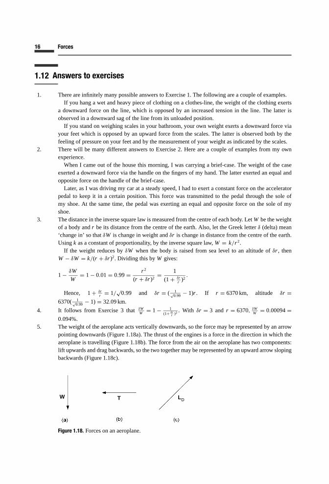
5. The weight of the aeroplane acts vertically downwards, so the force may be represented by an arrowpointing downwards (Figure 1.18a). The thrust of the engines is a force in the direction in which theaeroplane is travelling (Figure 1.18b). The force from the air on the aeroplane has two components:lift upwards and drag backwards, so the two together may be represented by an upward arrow slopingbackwards (Figure 1.18c).
LDTW
Figure 1.18. Forces on an aeroplane.
17 1.12 Answers to exercises
LD
T
W
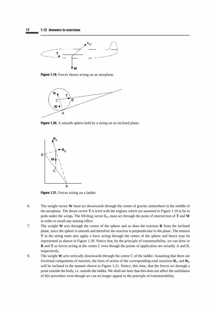
Figure 1.19. Forces shown acting on an aeroplane.
RT
W
Figure 1.20. A smooth sphere held by a string on an inclined plane.
RA
RB
W
Figure 1.21. Forces acting on a ladder.
6. The weight vectorW must act downwards through the centre of gravity somewhere in the middle ofthe aeroplane. The thrust vectorT is level with the engines which are assumed in Figure 1.19 to be inpods under the wings. The lift/drag vectorLD must act through the point of intersection ofT andWin order to avoid any turning effect.
7. The weightW acts through the centre of the sphere and so does the reactionR from the inclinedplane, since the sphere is smooth and therefore the reaction is perpendicular to the plane. The tensionT in the string must also apply a force acting through the centre of the sphere and hence may berepresented as shown in Figure1.20. Notice that, by the principle of transmissibility, we can draw inR andT as forces acting at the centre C even though the points of application are actually A and B,respectively.
8. The weightW acts vertically downwards through the centre C of the ladder. Assuming that there arefrictional components of reaction, the lines of action of the corresponding total reactionsRA andRB
will be inclined in the manner shown in Figure 1.21. Notice, this time, that the forces act through apoint outside the body, i.e. outside the ladder. We shall see later that this does not affect the usefulnessof this procedure even though we can no longer appeal to the principle of transmissibility.

18 Forces
F
F
F F
FF
Figure 1.22. A rod acted on by two coplanar forces.
F FF F
Figure 1.23. A rod in equilibriumunder the action of two forces.
1
1
1
1
1
Figure 1.24. Testing the parallelogram law.
9. If the forces are equal and opposite and perpendicular to the rod (Figure 1.22a), the forces would startto rotate the rod. If the force at end A is as before, but that at end B is along its length (Figure 1.22b),the rod would start to both rotate and translate. If the forces both act in the same direction (Figure1.22c), the rod would start to translate in that direction.Obviously, there are many more possible examples but moving on to those which result in equilib-
rium, we remember that for this to exist, the two forces must not only be equal in magnitude but alsoopposite in direction and collinear. For the latter to be true, both forces must act along the length ofthe rod. Then to be opposite in direction as well, they must either both pull outwards (Figure 1.23a)or both push inwards (Figure 1.23b).
10. Draw three straight lines from a point P1 in exactly the directions of the bands PA, PB and PC shownin Figure 1.9. Mark off distances from P1 proportional to the band extensions and therefore to theirtensions. Denote these distancemarks A1, B1 and C1, respectively, as shown in Figure 1.24. Completethe parallelogram on the sidesP1A1 andP1C1, and denote the fourth corner D1. If the parallelogramlaw for the resultant of two forces holds, the diagonalP1D1 should be collinear with and of equallength toP1B1.Note that the parallelogram law may also be tested by completing a parallelogram on the sides
P1A1 andP1B1 or onP1B1 andP1C1.11. Referring to Figure 1.25,F1x = F1 cosθ1 = 1/2. F1y = F1 sinθ1 = √
3/2. F2x = F2 cosθ2 =2√3/2= √
3. F2y = F2 sinθ2 = 2/2= 1.

19 1.12 Answers to exercises
F1 R
F2
Figure 1.25. ResultantR of two forcesF1 andF2 acting at a point.
F1 F3
F2
Figure 1.26. Triangle of forces.
ThusRx = F1x + F2x = 1
2+ √
3= 1+ 2√3
2and Ry = F1y + F2y =
√3
2+ 1=
√3+ 2
2R2 = R2
x + R2y = 5+ 2
√3, R = 2.91N
tanφ = Ry/Rx =√3+ 2
1+ 2√3, φ = 39.9◦.
12. (a) Calculate the Cartesian components ofF1, F2 andF3 as follows.F1x = √6 cos 45◦ = √
6/√2=√
3, F2x = − (1+ √3), F3x = 2 cos(−60◦) = 1, F1y = √
6 sin 45◦ = √6/
√2= √
3, F2y =0, F3y =2 sin(−60◦) = 2(−√
3/2)= −√3. Then thex- andy-components of the resultant are:
Rx = F1x + F2x + F3x = √3− (1+ √
3)+ 1= 0 and
Ry = F1y + F2y + F3y = √3+ 0− √
3= 0.
Hence, the resultantR = 0 and the forcesF1, F2 andF3 are in equilibrium.(b) Draw the vectors corresponding toF1, F2 andF3 end-on-end as shown in Figure 1.26. Since
they form the sides of a triangle, the forces must be in equilibrium. Note that the order in which thevectors are joined does not matter provided that all point the same way around the triangle, i.e. allclockwise or all anti-clockwise.(c) Referring to Figure 1.27: F1
sin 120◦ =√6
sin 120◦ = 2.828, F2sin 105◦ = 1+√
3sin 105◦ = 2.828 and F3
sin 135◦ =2
sin 135◦ = 2.828. The forces are in equilibrium since the magnitude of each is proportional to the sineof the angle between the other two.
13. (a)F1x =2 cos 150◦ =2(−√3/2)= − √
3, F2x = √6 cos 45◦ = √
6/√2= √
3, F3x =2 cos(−60◦)=2/2= 1, F4x = √
2 cos(−135◦) = √2(−1/
√2)= −1. Therefore,Rx = F1x + F2x + F3x + F4x =
−√3+ √
3+ 1− 1= 0.F1y =2 sin 150◦ =2/2=1, F2y = √
6 sin 45◦ = √6/
√2= √
3, F3y =2 sin(−60◦) = 2(−√3/2)=
−√3, F4y = √
2 sin(−135◦) = √2(−1/
√2)= −1.Therefore,Ry = F1y + F2y + F3y + F4y = 1+√
3− √3− 1= 0.
Since bothRx andRy are zero, the resultantR is zero and therefore the four forcesF1, F2, F3 andF4 are in equilibrium.

20 Forces
F1
F3
F2
°°
°
Figure 1.27. Three forces acting at a point.
F1 F4
F3
F2
Figure 1.28. Tetragon of forces.
ax
ay
az
a
P
O
Figure 1.29. Vectora in three-dimensional space.
(b) Draw the vectors corresponding toF1, F2, F3 andF4 end-on-end as shown in Figure 1.28. Sincethey complete the sides of a tetragon (four-sided polygon), by the polygon of forces, the forces mustbe in equilibrium.
14. Before answering the specific problem, let us consider the properties of a vectoraas shown supposedlyin three-dimensional space in Figure 1.29. This has been simplified by localizing the vectora at the
21 1.12 Answers to exercises
W2
W3
W1
°
Figure 1.30. Triangles of tension forces acting at C.
origin of the three-dimensional Cartesian coordinate system. If Pis the projection of the end ofaonto thex, y plane, by Pythagoras’ theorem,a2 = OP2 + a2z = a2x + a2y + a2z . In other words, thesquare of the length of a vector equals the sum of the squares of itsx-, y- andz-components. Also,ax = a cosθx, ay = a cosθy andaz = a cosθz, whereθx, θy andθz are the angles which the vectoramakes with the positivex-, y- andz-axes, respectively.Returning to the specific problem, the resultantR of the three forcesF1, F2 andF3 will have x-, y-
andz-components as follows:
Rx = F1x + F2x + F3x = 1+ 2− 2= 2
Ry = F1y + F2y + F3y = −2+ 1− 1= −2
Rz = F1z + F2z + F3z = −1− 1+ 1= −1.
Therefore,R = (2, −2, −1).R2 = R2
x + R2y + R2
z = 4+ 4+ 1= 9. Hence,R = 3N.
Rx = Rcosθx, θx = cos−1(2/3)= 48.2◦
Ry = Rcosθy, θy = cos−1(−2/3)= 131.8◦
Rz = Rcosθz, θz = cos−1(−1/3)= 109.5◦.
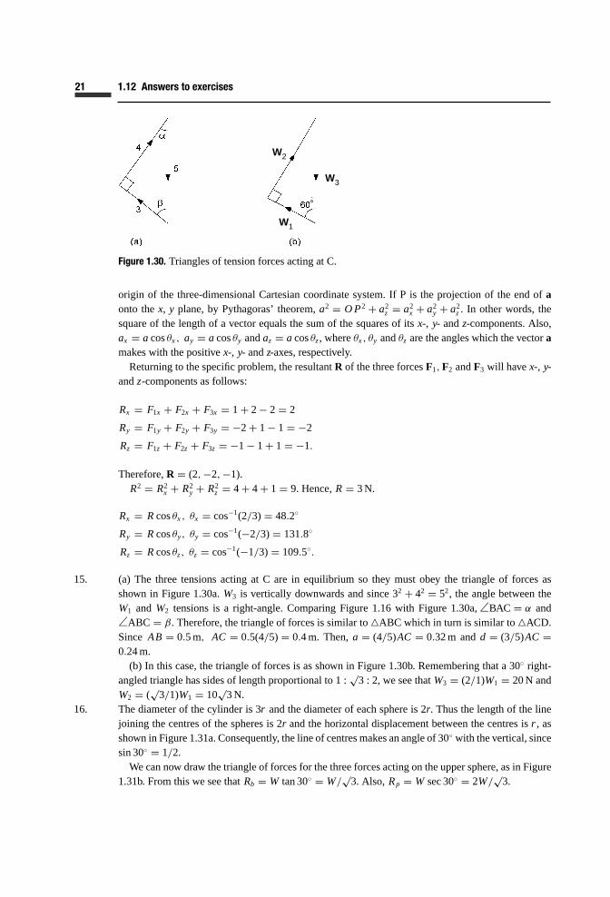
15. (a) The three tensions acting at C are in equilibrium so they must obey the triangle of forces asshown in Figure 1.30a.W3 is vertically downwards and since 32 + 42 = 52, the angle between theW1 andW2 tensions is a right-angle. Comparing Figure 1.16 with Figure 1.30a,∠BAC = α and∠ABC = β. Therefore, the triangle of forces is similar to�ABC which in turn is similar to�ACD.Since AB = 0.5m, AC = 0.5(4/5)= 0.4m. Then,a = (4/5)AC = 0.32m andd = (3/5)AC =0.24m.(b) In this case, the triangle of forces is as shown in Figure 1.30b. Remembering that a 30◦ right-
angled triangle has sides of length proportional to 1 :√3 : 2, we see thatW3 = (2/1)W1 = 20N and
W2 = (√3/1)W1 = 10
√3N.
16. The diameter of the cylinder is 3r and the diameter of each sphere is 2r. Thus the length of the linejoining the centres of the spheres is 2r and the horizontal displacement between the centres isr , asshown in Figure 1.31a. Consequently, the line of centresmakes an angle of 30◦ with the vertical, sincesin 30◦ = 1/2.We can now draw the triangle of forces for the three forces acting on the upper sphere, as in Figure
1.31b. From this we see thatRb = W tan 30◦ = W/√3. Also,Rp = W sec 30◦ = 2W/
√3.

22 Forces
Rb
Rp
W
°°
Figure 1.31. Triangle of forces acting on upper sphere.
Ra
Rc
Rp
W
°
Figure 1.32. Tetragon of forces acting on lower sphere.
Figure 1.33. Top view of the four spheres in the cylinder.
Next we draw the polygon of forces for the four forces acting on the lower sphere (see Figure 1.32).From this, we see thatRa = Rp sin 30◦ = 2W/2
√3= W/
√3. Also,Rc = W + Rp cos 30◦ = W +
2√3W
√32 = 2W.
17. Figure 1.33 shows the top view of the four spheres in the cylinder. Consider one of the top spheresand draw inx- andy-axes as shown with the origin at the centre of the sphere. Thez-axis will be atright-angles vertically upwards. The points of contact with the bottom spheres will be on the lines ofcentres below the points A andB. The top view diagram (Figure 1.33)shows thatAO = BO = r/
√2.
If P is the point of contact below A, we see from Figure 1.34 of the APO triangle in they, zplanethat PO and therefore the direction of the reaction force at P is at 45◦ to the vertical, PO being thesphere radiusr.

23 1.12 Answers to exercises
°
Figure 1.34. Triangle APO in the verticaly, z plane.
Figure 1.35. Horizontalx- andy-axes with origin at centre of left lower sphere.
We now deduce that the reaction force from P in the direction of O can be written in terms of itsCartesian components asRp = (0, −R/
√2, R/
√2), whereR is its magnitude. We now have another
reaction force at the point of contact Q below B given byRq = (−R/√2,0, R/
√2).
Since the top two spheres try to move down and out, we can assume that there will be no reactionforce between the two. However, there will be one from the wall of the cylinder directedtowardsO which can be written asRc = (Rc/
√2, Rc/
√2,0), whereRc is the magnitude and itsx- and y-
components are at 45◦ to the direction ofRc. Finally, the weight of thesphere can be written as theforceW = (0,0, −W).Hence, the sphere is kept in equilibrium by the four forcesRp, Rq, Rc andW all acting through its
centre O. For equilibrium, the sum of thex- components must be zero, the sum of they-componentsmust be zero and the sum of thez-components must be zero. Thus, 0− R/
√2+ Rc/
√2+ 0= 0 and
−R/√2+ 0+ Rc/
√2+ 0= 0, eachofwhich implies thatR = Rc, andR/
√2+ R/
√2+ 0− W =
0, i.e.R = W/√2.
Now consider the bottom two spheres. The top two try to push them apart, so we can assume thatthere is no reactive force between the bottom two spheres. Again, because of symmetry, we only needto study one of the spheres. Let us take the oneon the left and draw inx- andy-axes with origin atthe centre as shown in Figure 1.35. Thez-axis will again be vertically upwards. The point D is thepoint of contact with the cylinder and a reactive force will act on the sphere at D towards its centre.This force may be written asRd = (Rd/
√2, Rd/
√2,0). The points of contact with the upper spheres
are above M and N in Figure 1.35 and the corresponding downward sloping forces acting on ourbottom sphere can be written asRm = (0, −R/
√2, −R/
√2) andRn = (−R/
√2,0, −R/
√2). We
have already shown thatR = W/√2, soR/
√2= W/2.
Besides these three forces,wehave theweight of the sphereW = (0,0, −W) andanupward reactionforce through the base of the sphere given byRb = (0,0, Rb).There are thus five forces acting on the sphere through its centre. For equilibrium we can in
turn equate to zero the sum of thex-components, the sum of they-components and the sum of the
24 Forces
z-components. Hence,Rd/√2+ 0− W/2+ 0+ 0= 0 andRd/
√2− W/2+ 0+ 0+ 0= 0, each
of which givesRd = W/√2, and 0− W/2− W/2− W + Rb = 0, i.e.Rb = 2W.
To summarize the results: (1) the force between each top sphere and the cylinder isW/√2; (2) the
forces at the points of contact between upper and lower spheres are each equal toW/√2; (3) the force
between each bottom sphere and the cylinder isW/√2; (4) the force between each bottom sphere
and the base of the cylinder is 2W.
Related Documents