Static, free vibration and buckling analyses of stiffened plates by CS-FEM-DSG3 using triangular elements T. Nguyen-Thoi a,b,⇑ , T. Bui-Xuan a , P. Phung-Van b , H. Nguyen-Xuan a,b , P. Ngo-Thanh a a Department of Mechanics, Faculty of Mathematics & Computer Science, University of Science, Vietnam National University HCMC, 227 Nguyen Van Cu, Dist. 5, Hochiminh City, Viet Nam b Division of Computational Mechanics, Ton Duc Thang University, Nguyen Huu Tho St., Tan Phong Ward, Dist. 7, Hochiminh City, Viet Nam article info Article history: Received 24 July 2012 Accepted 24 April 2013 Keywords: Smoothed finite element methods (S-FEM) Eccentricity Stiffened plate Finite element method (FEM) Cell-based smoothed discrete shear gap method (CS-DSG3) Triangular elements abstract The paper presents the static, free vibration and buckling analyses of eccentrically stiffened plates by the cell-based smoothed discrete shear gap method (CS-FEM-DSG3) using triangular elements. In this method, the original plate element CS-DSG3 is combined with a membrane element and stiffened by a thick beam element. The eccentricity between the plate and the beam is included in the formulation of the beam. The compatibility of deflection and rotations of stiffeners and plate is assumed at the contact positions. The accuracy and reliability of the proposed method is verified by comparing its numerical solutions with those of analytical solutions, experimental results and others available numerical results. Ó 2013 Elsevier Ltd. All rights reserved. 1. Introduction Nowadays, the stiffened plates have been used widely in many branches of structural engineering such as aircraft, ships, bridges, buildings, etc. In early investigations, the analytical or semi-analyt- ical methods have been used to analyse these stiffened plates. Ramakrishnan and Kunukkasseril [1] presented an analytical method for free vibration analysis of deck and their results were compared with the experimental results. Mukhopadhyay proposed a semi-analytical method for vibration and stability analyses [2–4] and for bending analysis [5] of concentrically and eccentrically stiffened plates. Chan et al. [6] proposed an exact solution by using the U-transformation method for the static analysis of stiffened plates whose rid-stiffeners were concentrically and periodically placed. However, those models are usually complex or possess inherent drawbacks in the methodology. Later, many different numerical models relied on simpler and more efficient methodologies have been proposed such as finite difference method, finite element method (FEM), boundary element method, meshfree methods, etc. Among them, the FEM shows many advantages compared to others methods. In the FEM, the stiffened plate is often separated into the plate and the stiffener. Then, the plate is modelled by plate elements and the stiffeners are modelled by beam elements. For modelling the plate elements in the stiffened plates, the investiga- tors have used the Kirchhoff thin plate theory as well as the Mind- lin–Reissner thick plate theory. Based on the Kirchhoff theory, some typical works can be found in Refs. [7–10]. Rossow and Ibrahimkhail [7] applied the constraint method to the finite element of which approximating polynomials had arbitrary order for static analysis of concentrically and eccen- trically stiffened plates. Olson and Hazel [8] presented theoretical and experimental results for free vibration analysis of eccentrically stiffened plates. The natural frequencies of clamped stiffened plates having one stiffener and two stiffeners were predicted by the triangular high-precision conforming element. Barik [9] and Barik and Mukhopadhyay [10] combined the four-node rectangular plane-stress element with the plate-bending ACM element for sta- tic, free vibration, and pre-buckling analyses of arbitrary bare and stiffened plates. Based on the Mindlin–Reissner theory, some typical works can be found in Refs. [11–16]. Deb and Booton [11] used an isopara- metric stiffened plate element under transverse load, then Mukheriee and Mukhoadhyay [12,13] also used this element for free vibration and buckling analysis. However, the isoparametric plate element is suffered the shear-locking phenomena [14] that was not mentioned in those works. Palani et al. [15] then applied two isoparametric elements (the eight-node isoparametric element 0045-7949/$ - see front matter Ó 2013 Elsevier Ltd. All rights reserved. http://dx.doi.org/10.1016/j.compstruc.2013.04.027 ⇑ Corresponding author. Address: Faculty of Mathematics & Computer Science, University of Science, Vietnam National University HCMC, 227 Nguyen Van Cu, Dist. 5, Hochiminh City, Viet Nam. Tel.: +84 942340411. E-mail addresses: [email protected], [email protected] (T. Nguyen- Thoi). Computers and Structures 125 (2013) 100–113 Contents lists available at SciVerse ScienceDirect Computers and Structures journal homepage: www.elsevier.com/locate/compstruc

Welcome message from author
This document is posted to help you gain knowledge. Please leave a comment to let me know what you think about it! Share it to your friends and learn new things together.
Transcript
Computers and Structures 125 (2013) 100–113
Contents lists available at SciVerse ScienceDirect
Computers and Structures
journal homepage: www.elsevier .com/locate/compstruc
Static, free vibration and buckling analyses of stiffened platesby CS-FEM-DSG3 using triangular elements
0045-7949/$ - see front matter � 2013 Elsevier Ltd. All rights reserved.http://dx.doi.org/10.1016/j.compstruc.2013.04.027
⇑ Corresponding author. Address: Faculty of Mathematics & Computer Science,University of Science, Vietnam National University HCMC, 227 Nguyen Van Cu, Dist.5, Hochiminh City, Viet Nam. Tel.: +84 942340411.
E-mail addresses: [email protected], [email protected] (T. Nguyen-Thoi).
T. Nguyen-Thoi a,b,⇑, T. Bui-Xuan a, P. Phung-Van b, H. Nguyen-Xuan a,b, P. Ngo-Thanh a
a Department of Mechanics, Faculty of Mathematics & Computer Science, University of Science, Vietnam National University HCMC, 227 Nguyen Van Cu, Dist. 5, Hochiminh City, VietNamb Division of Computational Mechanics, Ton Duc Thang University, Nguyen Huu Tho St., Tan Phong Ward, Dist. 7, Hochiminh City, Viet Nam
a r t i c l e i n f o
Article history:Received 24 July 2012Accepted 24 April 2013
Keywords:Smoothed finite element methods (S-FEM)EccentricityStiffened plateFinite element method (FEM)Cell-based smoothed discrete shear gapmethod (CS-DSG3)Triangular elements
a b s t r a c t
The paper presents the static, free vibration and buckling analyses of eccentrically stiffened plates by thecell-based smoothed discrete shear gap method (CS-FEM-DSG3) using triangular elements. In thismethod, the original plate element CS-DSG3 is combined with a membrane element and stiffened by athick beam element. The eccentricity between the plate and the beam is included in the formulationof the beam. The compatibility of deflection and rotations of stiffeners and plate is assumed at the contactpositions. The accuracy and reliability of the proposed method is verified by comparing its numericalsolutions with those of analytical solutions, experimental results and others available numerical results.
� 2013 Elsevier Ltd. All rights reserved.
1. Introduction others methods. In the FEM, the stiffened plate is often separated
Nowadays, the stiffened plates have been used widely in manybranches of structural engineering such as aircraft, ships, bridges,buildings, etc. In early investigations, the analytical or semi-analyt-ical methods have been used to analyse these stiffened plates.Ramakrishnan and Kunukkasseril [1] presented an analyticalmethod for free vibration analysis of deck and their results werecompared with the experimental results. Mukhopadhyay proposeda semi-analytical method for vibration and stability analyses [2–4]and for bending analysis [5] of concentrically and eccentricallystiffened plates. Chan et al. [6] proposed an exact solution by usingthe U-transformation method for the static analysis of stiffenedplates whose rid-stiffeners were concentrically and periodicallyplaced.
However, those models are usually complex or possess inherentdrawbacks in the methodology. Later, many different numericalmodels relied on simpler and more efficient methodologies havebeen proposed such as finite difference method, finite elementmethod (FEM), boundary element method, meshfree methods,etc. Among them, the FEM shows many advantages compared to
into the plate and the stiffener. Then, the plate is modelled by plateelements and the stiffeners are modelled by beam elements. Formodelling the plate elements in the stiffened plates, the investiga-tors have used the Kirchhoff thin plate theory as well as the Mind-lin–Reissner thick plate theory.
Based on the Kirchhoff theory, some typical works can be foundin Refs. [7–10]. Rossow and Ibrahimkhail [7] applied the constraintmethod to the finite element of which approximating polynomialshad arbitrary order for static analysis of concentrically and eccen-trically stiffened plates. Olson and Hazel [8] presented theoreticaland experimental results for free vibration analysis of eccentricallystiffened plates. The natural frequencies of clamped stiffenedplates having one stiffener and two stiffeners were predicted bythe triangular high-precision conforming element. Barik [9] andBarik and Mukhopadhyay [10] combined the four-node rectangularplane-stress element with the plate-bending ACM element for sta-tic, free vibration, and pre-buckling analyses of arbitrary bare andstiffened plates.
Based on the Mindlin–Reissner theory, some typical works canbe found in Refs. [11–16]. Deb and Booton [11] used an isopara-metric stiffened plate element under transverse load, thenMukheriee and Mukhoadhyay [12,13] also used this element forfree vibration and buckling analysis. However, the isoparametricplate element is suffered the shear-locking phenomena [14] thatwas not mentioned in those works. Palani et al. [15] then appliedtwo isoparametric elements (the eight-node isoparametric element
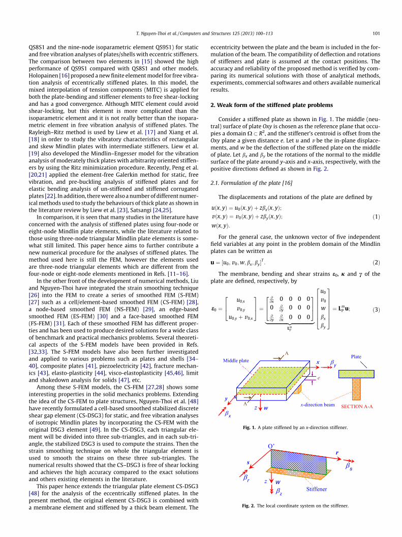
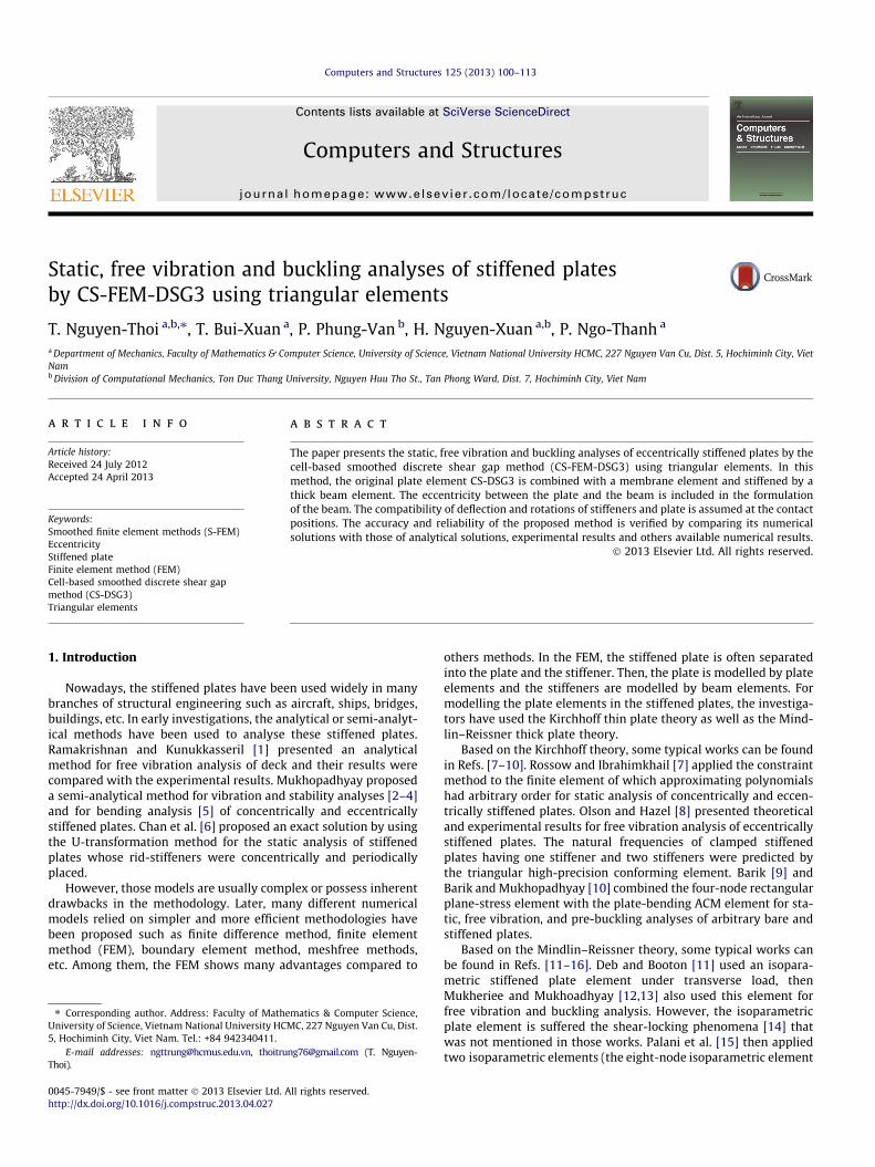
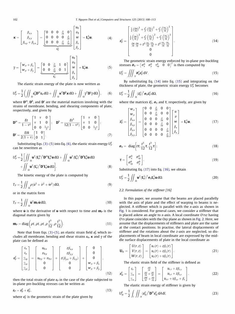
Fig. 1. A plate stiffened by an x-direction stiffener.
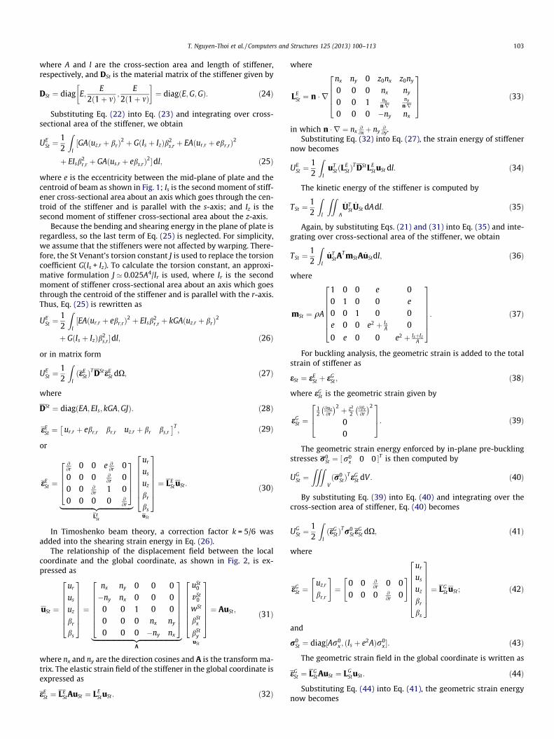
Fig. 2. The local coordinate system on the stiffener.
T. Nguyen-Thoi et al. / Computers and Structures 125 (2013) 100–113 101
QS8S1 and the nine-node isoparametric element QS9S1) for staticand free vibration analyses of plates/shells with eccentric stiffeners.The comparison between two elements in [15] showed the highperformance of QS9S1 compared with QS8S1 and other models.Holopainen [16] proposed a new finite element model for free vibra-tion analysis of eccentrically stiffened plates. In this model, themixed interpolation of tension components (MITC) is applied forboth the plate-bending and stiffener elements to free shear-lockingand has a good convergence. Although MITC element could avoidshear-locking, but this element is more complicated than theisoparametric element and it is not really better than the isopara-metric element in free vibration analysis of stiffened plates. TheRayleigh–Ritz method is used by Liew et al. [17] and Xiang et al.[18] in order to study the vibratory characteristics of rectangularand skew Mindlin plates with intermediate stiffeners. Liew et al.[19] also developed the Mindlin–Engesser model for the vibrationanalysis of moderately thick plates with arbitrarity oriented stiffen-ers by using the Ritz minimization procedure. Recently, Peng et al.[20,21] applied the element-free Galerkin method for static, freevibration, and pre-buckling analysis of stiffened plates and forelastic bending analysis of un-stiffened and stiffened corrugatedplates [22]. In addition, there were also a number of different numer-ical methods used to study the behaviours of thick plate as shown inthe literature review by Liew et al. [23], Satsangi [24,25].
In comparison, it is seen that many studies in the literature haveconcerned with the analysis of stiffened plates using four-node oreight-node Mindlin plate elements, while the literature related tothose using three-node triangular Mindlin plate elements is some-what still limited. This paper hence aims to further contribute anew numerical procedure for the analyses of stiffened plates. Themethod used here is still the FEM, however the elements usedare three-node triangular elements which are different from thefour-node or eight-node elements mentioned in Refs. [11–16].
In the other front of the development of numerical methods, Liuand Nguyen-Thoi have integrated the strain smoothing technique[26] into the FEM to create a series of smoothed FEM (S-FEM)[27] such as a cell/element-based smoothed FEM (CS-FEM) [28],a node-based smoothed FEM (NS-FEM) [29], an edge-basedsmoothed FEM (ES-FEM) [30] and a face-based smoothed FEM(FS-FEM) [31]. Each of these smoothed FEM has different proper-ties and has been used to produce desired solutions for a wide classof benchmark and practical mechanics problems. Several theoreti-cal aspects of the S-FEM models have been provided in Refs.[32,33]. The S-FEM models have also been further investigatedand applied to various problems such as plates and shells [34–40], composite plates [41], piezoelectricity [42], fracture mechan-ics [43], elasto-plasticity [44], visco-elastoplasticity [45,46], limitand shakedown analysis for solids [47], etc.
Among these S-FEM models, the CS-FEM [27,28] shows someinteresting properties in the solid mechanics problems. Extendingthe idea of the CS-FEM to plate structures, Nguyen-Thoi et al. [48]have recently formulated a cell-based smoothed stabilized discreteshear gap element (CS-DSG3) for static, and free vibration analysesof isotropic Mindlin plates by incorporating the CS-FEM with theoriginal DSG3 element [49]. In the CS-DSG3, each triangular ele-ment will be divided into three sub-triangles, and in each sub-tri-angle, the stabilized DSG3 is used to compute the strains. Then thestrain smoothing technique on whole the triangular element isused to smooth the strains on these three sub-triangles. Thenumerical results showed that the CS–DSG3 is free of shear lockingand achieves the high accuracy compared to the exact solutionsand others existing elements in the literature.
This paper hence extends the triangular plate element CS-DSG3[48] for the analysis of the eccentrically stiffened plates. In thepresent method, the original element CS-DSG3 is combined witha membrane element and stiffened by a thick beam element. The
eccentricity between the plate and the beam is included in the for-mulation of the beam. The compatibility of deflection and rotationsof stiffeners and plate is assumed at the contact positions. Theaccuracy and reliability of the proposed method is verified by com-paring its numerical solutions with those of analytical methods,experiments, commercial softwares and others available numericalresults.
2. Weak form of the stiffened plate problems
Consider a stiffened plate as shown in Fig. 1. The middle (neu-tral) surface of plate Oxy is chosen as the reference plane that occu-pies a domain X � R2, and the stiffener’s centroid is offset from theOxy plane a given distance e. Let u and v be the in-plane displace-ments, and w be the deflection of the stiffened plate on the middleof plate. Let bx and by be the rotations of the normal to the middlesurface of the plate around y-axis and x-axis, respectively, with thepositive directions defined as shown in Fig. 2.
2.1. Formulation of the plate [16]
The displacements and rotations of the plate are defined by
uðx; yÞ ¼ u0ðx; yÞ þ zbxðx; yÞ;vðx; yÞ ¼ v0ðx; yÞ þ zbyðx; yÞ;wðx; yÞ:
ð1Þ
For the general case, the unknown vector of five independentfield variables at any point in the problem domain of the Mindlinplates can be written as
u ¼ ½u0; v0;w;bx;by�T: ð2Þ
The membrane, bending and shear strains e0, j and c of theplate are defined, respectively, by
e0 ¼u0;x
v0;y
u0;y þ v0;x
264375 ¼
@@x 0 0 0 00 @
@y 0 0 0@@y
@@x 0 0 0
264375
|fflfflfflfflfflfflfflfflfflfflfflfflfflfflfflfflffl{zfflfflfflfflfflfflfflfflfflfflfflfflfflfflfflfflffl}Lm
P
u0
v0
w
bx
by
26666664
37777775 ¼ LmP u; ð3Þ
102 T. Nguyen-Thoi et al. / Computers and Structures 125 (2013) 100–113
j ¼bx;x
by;y
bx;y þ by;x
264375 ¼ 0 0 0 @
@x 00 0 0 0 @
@x
0 0 0 @@y
@@x
264375
|fflfflfflfflfflfflfflfflfflfflfflfflfflfflfflfflffl{zfflfflfflfflfflfflfflfflfflfflfflfflfflfflfflfflffl}Lb
P
u0
v0
w
bx
by
26666664
37777775 ¼ LbPu; ð4Þ
c ¼w;x þ bx
w;y þ by
" #¼
0 0 @@x 1 0
0 0 @@y 0 1
" #|fflfflfflfflfflfflfflfflfflfflfflfflfflfflfflfflffl{zfflfflfflfflfflfflfflfflfflfflfflfflfflfflfflfflffl}
LsP
u0
v0
w
bx
by
26666664
37777775 ¼ LsPu: ð5Þ
The elastic strain energy of the plate is now written as
UEP ¼
12
ZZXeT
0Dme0 dXþZZ
XjT DbjdXþ
ZZXcT DscdX
� �; ð6Þ
where Dm, Db, and Ds are the material matrices involving with thestrains of membrane, bending, and shearing components of plate,respectively, and given by
Dm ¼ Et1� m2
1 m 0m 1 00 0 1�m
2
264375; Db ¼ Et3
12ð1� m2Þ
1 m 0m 1 00 0 1�m
2
264375;
Ds ¼ Etk2ð1þ mÞ
1 00 1
� �: ð7Þ
Substituting Eqs. (3)–(5) into Eq. (6), the elastic strain energy UEP
can be rewritten as
UEP ¼
12
ZZX
uTðLmP Þ
T DmLmP udXþ
ZZX
uTðLbPÞ
T DbLbPudX
�þZZ
XuTðLs
PÞT DsLs
PudX�: ð8Þ
The kinetic energy of the plate is computed by
TP ¼12
ZZXqð _u2 þ _v2 þ _w2ÞdX; ð9Þ
or in the matrix form
TP ¼12
ZZX
_uT mP _udX; ð10Þ
where _u is the derivative of u with respect to time and mP is thediagonal matrix given by
mP ¼ diag qt;qt;qt;qt3
12;q
t3
12
� �: ð11Þ
Note that from Eqs. (3)–(5), an elastic strain field eEP which in-
cludes all membrane, bending and shear strains e0, j and c of theplate can be defined as
eEP ¼
ex
ey
cxy
cxz
cyz
26666664
37777775 ¼u0;x
v0;y
u0;y þ v0;x
00
26666664
37777775þzbx;x
zby;y
zðby;x þ bx;yÞ00
26666664
37777775þ000
w;x þ bx
w;y þ by
26666664
37777775;ð12Þ
then the total strain of plate eP in the case of the plate subjected toin-plane pre-buckling stresses can be written as
eP ¼ eEP þ eG
P ; ð13Þ
where eGP is the geometric strain of the plate given by
eGP ¼
12
@w@x
� �2 þ z2
2@bx@x
� �2 þ z2
2@by
@x
2
12
@w@y
2þ z2
2@bx@y
2þ z2
2@by
@y
2
@w@x
@w@y þ z2 @bx
@x@bx@y þ z2 @by
@x@by
@y
00
26666666664
37777777775: ð14Þ
The geometric strain energy enforced by in-plane pre-bucklingstresses r0 ¼ r0
x r0y s0
xy 0 0� �T
is then computed by
UGP ¼
ZZZVrT
0eGP dV : ð15Þ
By substituting Eq. (14) into Eq. (15) and integrating on thethickness of plate, the geometric strain energy UG
P becomes
UGP ¼
12
ZZXðeG
P ÞTr0e
GP dX; ð16Þ
where the matrices eGP , r0 and s, respectively, are given by
eGP ¼
w;x
w;y
bx;x
bx;y
by;x
by;y
2666666664
3777777775¼
0 0 @@x 0 0
0 0 @@y 0 0
0 0 0 @@x 0
0 0 0 @@y 0
0 0 0 0 @@x
0 0 0 0 @@y
26666666664
37777777775
u
vw
bx
by
26666664
37777775 ¼ LGP u; ð17Þ
r0 ¼ diag ts;t3
12s;
t3
12s
� �; ð18Þ
s ¼r0
x r0xy
r0xy r0
y
" #: ð19Þ
Substituting Eq. (17) into Eq. (16), we obtain
UGP ¼
12
ZZX
uTðLGP Þ
Tr0LGP udX: ð20Þ
2.2. Formulation of the stiffener [16]
In this paper, we assume that the beams are placed parallellywith the axis of plate and the effect of warping to beams is ne-glected. A stiffener which is parallel with the x-axis as shown inFig. 1 is considered. For general cases, we consider a stiffener thatis placed askew an angle to x-axis. A local coordinate O0rsz havingO0rs plane coincides with the Oxy plane as shown in Fig. 2. Here, weassume that the displacements of stiffeners and plate are the sameat the contact positions. In practise, the lateral displacements ofstiffener and the rotations about the z-axis are neglected, so dis-placements of beam in local coordinate are expressed by the mid-dle surface displacements of plate in the local coordinate as
USt ¼Uðr; zÞVðr; zÞWðr; zÞ
264375 ¼ urðrÞ þ zbrðrÞ
usðrÞ þ zbsðrÞuzðrÞ þ sbsðrÞ
264375: ð21Þ
The elastic strain field of the stiffener is defined as
eESt ¼
er
crs
crz
264375 ¼
@U@r
@U@s þ @V
@r@W@r þ @U
@z
264375 ¼ ur;r þ zbr;r
us;r þ zbs;r
uz;r þ sbs;r þ br
264375: ð22Þ
The elastic strain energy of stiffener is given by
UESt ¼
12
Zl
ZZAðeE
StÞT DSteE
St dAdl; ð23Þ
T. Nguyen-Thoi et al. / Computers and Structures 125 (2013) 100–113 103
where A and l are the cross-section area and length of stiffener,respectively, and DSt is the material matrix of the stiffener given by
DSt ¼ diag E;E
2ð1þ mÞ ;E
2ð1þ mÞ
� �¼ diagðE;G;GÞ: ð24Þ
Substituting Eq. (22) into Eq. (23) and integrating over cross-sectional area of the stiffener, we obtain
UESt ¼
12
Zl½GAðuz;r þ brÞ
2 þ GðIs þ IzÞb2s;r þ EAður;r þ ebr;rÞ
2
þ EIsb2r;r þ GAðus;r þ ebs;rÞ
2�dl; ð25Þ
where e is the eccentricity between the mid-plane of plate and thecentroid of beam as shown in Fig. 1; Is is the second moment of stiff-ener cross-sectional area about an axis which goes through the cen-troid of the stiffener and is parallel with the s-axis; and Iz is thesecond moment of stiffener cross-sectional area about the z-axis.
Because the bending and shearing energy in the plane of plate isregardless, so the last term of Eq. (25) is neglected. For simplicity,we assume that the stiffeners were not affected by warping. There-fore, the St Venant’s torsion constant J is used to replace the torsioncoefficient G(Is + Iz). To calculate the torsion constant, an approxi-mative formulation J ’ 0.025A4/Ir is used, where Ir is the secondmoment of stiffener cross-sectional area about an axis which goesthrough the centroid of the stiffener and is parallel with the r-axis.Thus, Eq. (25) is rewritten as
UESt ¼
12
Zl½EAður;r þ ebr;rÞ
2 þ EIsb2r;r þ kGAðuz;r þ brÞ
2
þ GðIs þ IzÞb2s;r�dl; ð26Þ
or in matrix form
UESt ¼
12
ZlðeE
StÞT DSteE
St dX; ð27Þ
where
DSt ¼ diagðEA; EIs; kGA;GJÞ: ð28Þ
eESt ¼ ur;r þ ebr;r br;r uz;r þ br bs;r
� �T; ð29Þ
or
eESt ¼
@@r 0 0 e @
@r 00 0 0 @
@r 00 0 @
@r 1 00 0 0 0 @
@r
2666437775
|fflfflfflfflfflfflfflfflfflfflfflfflfflfflfflfflfflfflffl{zfflfflfflfflfflfflfflfflfflfflfflfflfflfflfflfflfflfflffl}LE
St
ur
us
uz
br
bs
26666664
37777775uSt
¼ LEStuSt: ð30Þ
In Timoshenko beam theory, a correction factor k = 5/6 wasadded into the shearing strain energy in Eq. (26).
The relationship of the displacement field between the localcoordinate and the global coordinate, as shown in Fig. 2, is ex-pressed as
uSt ¼
ur
us
uz
br
bs
26666664
37777775 ¼nx ny 0 0 0�ny nx 0 0 0
0 0 1 0 00 0 0 nx ny
0 0 0 �ny nx
26666664
37777775|fflfflfflfflfflfflfflfflfflfflfflfflfflfflfflfflfflfflfflfflfflfflfflffl{zfflfflfflfflfflfflfflfflfflfflfflfflfflfflfflfflfflfflfflfflfflfflfflffl}
A
uSt0
vSt0
wSt
bStx
bSty
26666664
37777775uSt
¼ AuSt ; ð31Þ
where nx and ny are the direction cosines and A is the transform ma-trix. The elastic strain field of the stiffener in the global coordinate isexpressed as
eESt ¼ LE
StAuSt ¼ LEStuSt: ð32Þ
where
LESt ¼ n � r
nx ny 0 z0nx z0ny
0 0 0 nx ny
0 0 1 nxn�r
ny
n�r0 0 0 �ny nx
2666437775 ð33Þ
in which n � r ¼ nx@@xþ ny
@@y.
Substituting Eq. (32) into Eq. (27), the strain energy of stiffenernow becomes
UESt ¼
12
Zl
uTStðL
EStÞ
T DStLEStuSt dl: ð34Þ
The kinetic energy of the stiffener is computed by
TSt ¼12
Zl
ZZA
_UTSt
_USt dAdl: ð35Þ
Again, by substituting Eqs. (21) and (31) into Eq. (35) and inte-grating over cross-sectional area of the stiffener, we obtain
TSt ¼12
Zl
_uTStA
T mStA _uStdl; ð36Þ
where
mSt ¼ qA
1 0 0 e 00 1 0 0 e
0 0 1 0 0e 0 0 e2 þ Is
A 0
0 e 0 0 e2 þ IsþIzA
26666664
37777775: ð37Þ
For buckling analysis, the geometric strain is added to the totalstrain of stiffener as
eSt ¼ eESt þ eG
St ; ð38Þ
where eGSt is the geometric strain given by
eGSt ¼
12
@uz@r
� �2 þ z2
2@br@r
� �2
00
264375: ð39Þ
The geometric strain energy enforced by in-plane pre-bucklingstresses r0
St ¼ ½r0x 0 0 �T is then computed by
UGSt ¼
ZZZVðr0
StÞTeG
St dV : ð40Þ
By substituting Eq. (39) into Eq. (40) and integrating over thecross-section area of stiffener, Eq. (40) becomes
UGSt ¼
12
ZlðeG
StÞTr0
SteGSt dX; ð41Þ
where
eGSt ¼
uz;r
br;r
" #¼
0 0 @@r 0 0
0 0 0 @@r 0
" # ur
us
uz
br
bs
26666664
37777775 ¼ LGStuSt; ð42Þ
and
r0St ¼ diag½Ar0
x ; ðIs þ e2AÞr0x �: ð43Þ
The geometric strain field in the global coordinate is written as
eGSt ¼ LG
StAuSt ¼ LGStuSt: ð44Þ
Substituting Eq. (44) into Eq. (41), the geometric strain energynow becomes
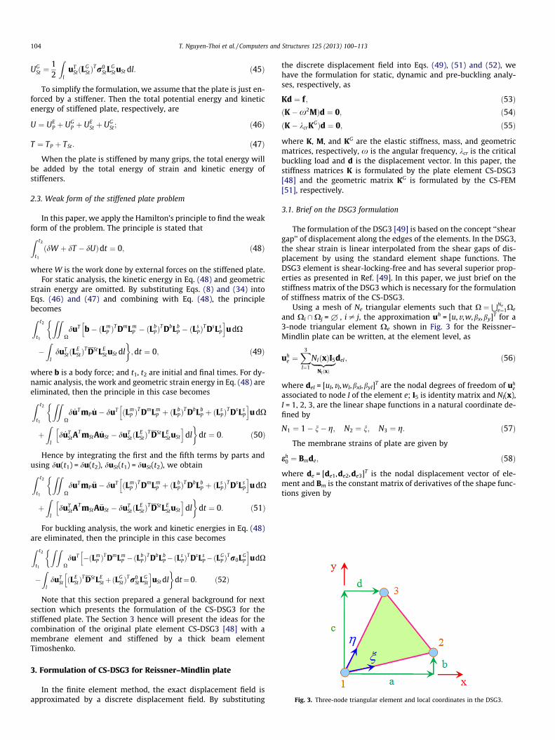
Fig. 3. Three-node triangular element and local coordinates in the DSG3.
104 T. Nguyen-Thoi et al. / Computers and Structures 125 (2013) 100–113
UGSt ¼
12
Zl
uTStðL
GStÞ
Tr0StL
GStuSt dl: ð45Þ
To simplify the formulation, we assume that the plate is just en-forced by a stiffener. Then the total potential energy and kineticenergy of stiffened plate, respectively, are
U ¼ UEP þ UG
P þ UESt þ UG
St; ð46Þ
T ¼ TP þ TSt: ð47Þ
When the plate is stiffened by many grips, the total energy willbe added by the total energy of strain and kinetic energy ofstiffeners.
2.3. Weak form of the stiffened plate problem
In this paper, we apply the Hamilton’s principle to find the weakform of the problem. The principle is stated thatZ t2
t1
ðdW þ dT � dUÞdt ¼ 0; ð48Þ
where W is the work done by external forces on the stiffened plate.For static analysis, the kinetic energy in Eq. (48) and geometric
strain energy are omitted. By substituting Eqs. (8) and (34) intoEqs. (46) and (47) and combining with Eq. (48), the principlebecomesZ t2
t1
ZZXduT b� ðLm
P ÞT DmLm
P � ðLbPÞ
T DbLbP � ðL
sPÞ
T DsLsP
h iudX
�Z
lduT
StðLEStÞ
T DStLEStuSt dl
�;dt ¼ 0; ð49Þ
where b is a body force; and t1, t2 are initial and final times. For dy-namic analysis, the work and geometric strain energy in Eq. (48) areeliminated, then the principle in this case becomesZ t2
t1
ZZXd _uT mP _u� duT ðLm
P ÞT DmLm
P þ ðLbPÞ
T DbLbP þ ðL
sPÞ
T DsLsP
h iudX
þZ
ld _uT
StAT mStA _uSt � duT
StðLEStÞ
T DStLEStuSt
h idl�
dt ¼ 0: ð50Þ
Hence by integrating the first and the fifth terms by parts andusing du(t1) = du(t2), duSt(t1) = duSt(t2), we obtainZ t2
t1
ZZXduT mP €u� duT ðLm
P ÞT DmLm
P þ ðLbPÞ
T DbLbP þ ðL
sPÞ
T DsLsP
h iudX
þZ
lduT
StAT mStA€uSt � duT
StðLEStÞ
T DStLEStuSt
h idl�
dt ¼ 0: ð51Þ
For buckling analysis, the work and kinetic energies in Eq. (48)are eliminated, then the principle in this case becomesZ t2
t1
Z ZXduT �ðLm
P ÞT DmLm
P �ðLbPÞ
T DbLbP�ðL
sPÞ
T DsLsP�ðL
GP Þ
Tr0LGP
h iudX
�Z
lduT
St ðLEStÞ
T DStLEStþðL
GStÞ
Tr0StL
GSt
h iuSt dl
�dt¼0: ð52Þ
Note that this section prepared a general background for nextsection which presents the formulation of the CS-DSG3 for thestiffened plate. The Section 3 hence will present the ideas for thecombination of the original plate element CS-DSG3 [48] with amembrane element and stiffened by a thick beam elementTimoshenko.
3. Formulation of CS-DSG3 for Reissner–Mindlin plate
In the finite element method, the exact displacement field isapproximated by a discrete displacement field. By substituting
the discrete displacement field into Eqs. (49), (51) and (52), wehave the formulation for static, dynamic and pre-buckling analy-ses, respectively, as
Kd ¼ f; ð53ÞðK�x2MÞd ¼ 0; ð54ÞðK� kcrK
GÞd ¼ 0; ð55Þ
where K, M, and KG are the elastic stiffness, mass, and geometricmatrices, respectively, x is the angular frequency, kcr is the criticalbuckling load and d is the displacement vector. In this paper, thestiffness matrices K is formulated by the plate element CS-DSG3[48] and the geometric matrix KG is formulated by the CS-FEM[51], respectively.
3.1. Brief on the DSG3 formulation
The formulation of the DSG3 [49] is based on the concept ‘‘sheargap’’ of displacement along the edges of the elements. In the DSG3,the shear strain is linear interpolated from the shear gaps of dis-placement by using the standard element shape functions. TheDSG3 element is shear-locking-free and has several superior prop-erties as presented in Ref. [49]. In this paper, we just brief on thestiffness matrix of the DSG3 which is necessary for the formulationof stiffness matrix of the CS-DSG3.
Using a mesh of Ne triangular elements such that X ¼SNe
e¼1Xe
and Xi \Xj = £ , i – j, the approximation uh = [u,v,w,bx,by]T for a3-node triangular element Xe shown in Fig. 3 for the Reissner–Mindlin plate can be written, at the element level, as
uhe ¼
X3
I¼1
NIðxÞI5|fflfflfflffl{zfflfflfflffl}NIðxÞ
deI; ð56Þ
where deI = [uI,vI,wI,bxI,byI]T are the nodal degrees of freedom of uhe
associated to node I of the element e; I5 is identity matrix and NI(x),I = 1, 2, 3, are the linear shape functions in a natural coordinate de-fined by
N1 ¼ 1� n� g; N2 ¼ n; N3 ¼ g: ð57Þ
The membrane strains of plate are given by
eh0 ¼ Bmde; ð58Þ
where de = [de1,de2,de3]T is the nodal displacement vector of ele-ment and Bm is the constant matrix of derivatives of the shape func-tions given by
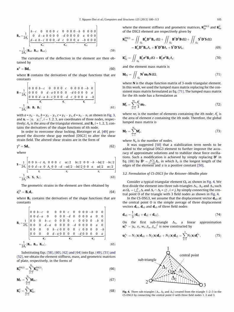
Fig. 4. Three sub-triangles (D1, D2 and D3) created from the triangle 1–2–3 in theCS-DSG3 by connecting the central point O with three field nodes 1, 2 and 3.
T. Nguyen-Thoi et al. / Computers and Structures 125 (2013) 100–113 105
Bm ¼1
2Ae
b� c 0 0 0 00 d�a 0 0 0
d�a b� c 0 0 0|fflfflfflfflfflfflfflfflfflfflfflfflfflfflfflfflffl{zfflfflfflfflfflfflfflfflfflfflfflfflfflfflfflfflffl}Bm1
c 0 0 0 00 �d 0 0 0�d c 0 0 0|fflfflfflfflfflfflfflfflfflfflfflfflffl{zfflfflfflfflfflfflfflfflfflfflfflfflffl}
Bm2
�b 0 0 0 00 a 0 0 0a �b 0 0 0|fflfflfflfflfflfflfflfflfflfflfflfflffl{zfflfflfflfflfflfflfflfflfflfflfflfflffl}
Bm3
26666664
37777775¼ 1
2AeBm1 Bm2 Bm3½ �: ð59Þ
The curvatures of the deflection in the element are then ob-tained by
jh ¼ Bde; ð60Þ
where B contains the derivatives of the shape functions that areconstants
B¼ 12Ae
0 0 0 b� c 00 0 0 0 d�a
0 0 0 d�a b� c|fflfflfflfflfflfflfflfflfflfflfflfflfflfflfflfflffl{zfflfflfflfflfflfflfflfflfflfflfflfflfflfflfflfflffl}B1
0 0 0 c 00 0 0 0 �d
0 0 0 �d c|fflfflfflfflfflfflfflfflfflfflfflfflffl{zfflfflfflfflfflfflfflfflfflfflfflfflffl}B2
0 0 0 �b 00 0 0 0 a
0 0 0 a �b|fflfflfflfflfflfflfflfflfflfflfflfflffl{zfflfflfflfflfflfflfflfflfflfflfflfflffl}B3
26666664
37777775¼ 1
2AeB1 B2 B3½ � ð61Þ
with a = x2 � x1, b = y2 � y1, c = y3 � y1, d = x3 � x1 as shown in Fig. 3,and xi ¼ xi yi½ �T , i ¼ 1;2;3, are coordinates of three nodes, respec-tively; Ae is the area of the triangular element, and Bi, i = 1, 2, 3, con-tains the derivatives of the shape functions of ith node.
In order to overcome shear locking, Bletzinger et al. [49] pro-posed the discrete shear gap method (DSG3) to alter the shearstrain field. The altered shear strains are in the form of
ch ¼ Sde; ð62Þ
where
S¼ 12Ae
0 0 b�c Ae 00 0 d�a 0 Ae|fflfflfflfflfflfflfflfflfflfflfflfflfflfflffl{zfflfflfflfflfflfflfflfflfflfflfflfflfflfflffl}
S1
0 0 c ac=2 bc=20 0 �d �ad=2 �bd=2|fflfflfflfflfflfflfflfflfflfflfflfflfflfflfflfflfflfflfflfflfflffl{zfflfflfflfflfflfflfflfflfflfflfflfflfflfflfflfflfflfflfflfflfflffl}
S3
0 0 �b �bd=2 �bc=20 0 a ad=2 ac=2|fflfflfflfflfflfflfflfflfflfflfflfflfflfflfflfflfflfflfflfflfflffl{zfflfflfflfflfflfflfflfflfflfflfflfflfflfflfflfflfflfflfflfflfflffl}
S3
2666437775
¼ 12Ae
S1 S2 S3½ �: ð63Þ
The geometric strains in the element are then obtained by
eGhP ¼ BGde; ð64Þ
where BG contains the derivatives of the shape functions that areconstants
BG ¼1
2Ae
0 0 b� c 0 00 0 d�a 0 00 0 0 b�c 00 0 0 d�a 00 0 0 0 b�c
0 0 0 0 d�a|fflfflfflfflfflfflfflfflfflfflfflfflfflfflfflfflfflfflfflffl{zfflfflfflfflfflfflfflfflfflfflfflfflfflfflfflfflfflfflfflffl}BG1
0 0 c 0 00 0 �d 0 00 0 0 c 00 0 0 �d 00 0 0 0 c
0 0 0 0 �d|fflfflfflfflfflfflfflfflfflfflfflfflfflfflffl{zfflfflfflfflfflfflfflfflfflfflfflfflfflfflffl}BG2
0 0 �b 0 00 0 a 0 00 0 0 �b 00 0 0 a 00 0 0 0 �b
0 0 0 0 a|fflfflfflfflfflfflfflfflfflfflfflfflfflfflffl{zfflfflfflfflfflfflfflfflfflfflfflfflfflfflffl}BG3
266666666666664
377777777777775¼ 1
2AeBG1 BG2 BG3½ �: ð65Þ
Substituting Eqs. (58), (60), (62) and (64) into Eqs. (49), (51) and(52), we obtain the element stiffness, mass, and geometric matricesof plate, respectively, in the forms of
KDSG3P ¼
XNe
e¼1
KDSG3Pe ; ð66Þ
MP ¼XNe
e¼1
MPe; ð67Þ
KGP ¼
XNe
e¼1
KGPe; ð68Þ
where the element stiffness and geometric matrices, KDSG3pe and KG
Pe
of the DSG3 element are respectively given by
KDSG3Pe ¼
ZZXe
BTmDmBm dXþ
ZZXe
BT DbB dXþZZ
Xe
ST DsSdX
¼ BTmDmBmAe þ BT DbBAe þ ST DsSAe; ð69Þ
KGPe ¼
ZZXe
BTGr
0BGdX ¼ BTGr
0BGAe; ð70Þ
and the element mass matrix is
MPe ¼ZZ
Xe
NT mPNdX; ð71Þ
where N is the shape function matrix of 3-node triangular element.In this work, we used the lumped mass matrix replacing for the con-sistent mass matrix formulated as Eq. (71). The lumped mass matrixfor the ith node has a formulation as
MiP ¼
Xnei
e¼1
Aie
3mP ; ð72Þ
where nei is the number of elements containing the ith node; Aie is
the area of element e containing the ith node. Therefore, the globallumped mass matrix is
MP ¼XNn
i¼1
MiP; ð73Þ
where Nn is the number of nodes.It was suggested [50] that a stabilization term needs to be
added to the original DSG3 element to further improve the accu-racy of approximate solutions and to stabilize shear force oscilla-tions. Such a modification is achieved by simply replacing Ds inEq. (69) by bDs ¼ kt3G
t2þah2e
I2, in which he is the longest length of theedges of the element and a is a positive constant [50].
3.2. Formulation of CS-DSG3 for the Reissner–Mindlin plate
Consider a typical triangular element Xe as shown in Fig. 4. Wefirst divide the element into three sub-triangles D1, D2 and D3 suchas Xe ¼
S3i¼1Di and Di \ Dj = £ , i – j, by simply connecting the cen-
tral point O of the triangle with 3 field nodes as shown in Fig. 4.In the CS-DSG3, we assume that the displacement vector deO at
the central point O is the simple average of three displacementvectors de1, de2 and de3 of three field nodes
deO ¼13ðde1 þ de2 þ de3Þ: ð74Þ
On the first sub-triangle D1, a linear approximationuD1
e ¼ ½ue;ve;we;bex;bey�T is now constructed by
uD1e ¼ N1ðxÞdeO þ N2ðxÞde1 þ N3ðxÞde2 ¼
X3
I¼1
NIðxÞdD1I ; ð75Þ
106 T. Nguyen-Thoi et al. / Computers and Structures 125 (2013) 100–113
where dD1 ¼ deO de1 de2½ �T is the vector of nodal degrees of free-dom of the sub-triangle D1; and NI(x), I = 1, 2, 3, are shape functionsin a natural coordinate defined by Eq. (57). The membrane strainseD1
0 , the curvatures of deflection jD1 , the altered shear strains cD1
and the geometric strains eGD1P in the sub-triangle D1 are then ob-
tained by
eD10 ¼ bD1
m1 bD1m2 bD1
m3
h i|fflfflfflfflfflfflfflfflfflfflfflfflfflfflfflffl{zfflfflfflfflfflfflfflfflfflfflfflfflfflfflfflffl}
bD1m
deO
de1
de2
26643775 ¼ bD1
m dD1 ;
jD1 ¼ bD11 bD1
2 bD13
h i|fflfflfflfflfflfflfflfflfflfflfflfflfflfflffl{zfflfflfflfflfflfflfflfflfflfflfflfflfflfflffl}
bD1
deO
de1
de2
26643775 ¼ bD1 dD1 ;
cD1 ¼ sD11 sD1
2 sD13
� �|fflfflfflfflfflfflfflfflfflfflfflfflffl{zfflfflfflfflfflfflfflfflfflfflfflfflffl}sD1
deO
de1
de2
26643775 ¼ sD1 dD1 ;
eGD1P ¼ bD1
G1 bD1G2 bD1
G3
h i|fflfflfflfflfflfflfflfflfflfflfflfflfflfflffl{zfflfflfflfflfflfflfflfflfflfflfflfflfflfflffl}
bD1G
deO
de1
de2
26643775 ¼ bD1
G dD1 ;
ð76Þ
where bD1m , bD1 , sD1 , and bD1
G are, respectively, computed similarly asthe matrices Bm, B, S, and BG of the DSG3 in Eqs. (59), (61), (63) and(65) but with two following changes: (1) coordinates of three nodexi = [xi,yi]T, i = 1, 2, 3 are replaced by xO, x1 and x2, respectively; and(2) the area Ae is replaced by the area AD1 of sub-triangle D1.
Substituting deO in Eq. (74) into Eq. (76), and then rearrangingwe obtain
eD10 ¼ 1
3 bD1m1 þ bD1
m213 bD1
m1 þ bD1m3
13 bD1
m1
h i|fflfflfflfflfflfflfflfflfflfflfflfflfflfflfflfflfflfflfflfflfflfflfflfflfflfflfflfflfflfflfflfflffl{zfflfflfflfflfflfflfflfflfflfflfflfflfflfflfflfflfflfflfflfflfflfflfflfflfflfflfflfflfflfflfflfflffl}
BD1m
de1
de2
de3
26643775 ¼ BD1
m de; ð77Þ
jD1 ¼ 13 bD1
1 þ bD12
13 bD1
1 þ bD13
13 bD1
1
h i|fflfflfflfflfflfflfflfflfflfflfflfflfflfflfflfflfflfflfflfflfflfflfflfflfflfflfflfflfflfflffl{zfflfflfflfflfflfflfflfflfflfflfflfflfflfflfflfflfflfflfflfflfflfflfflfflfflfflfflfflfflfflffl}
BD1
de1
de2
de3
264375 ¼ BD1 de; ð78Þ
cD1 ¼ 13 sD1
1 þ sD12
13 sD1
1 þ sD13
13 sD1
1
h i|fflfflfflfflfflfflfflfflfflfflfflfflfflfflfflfflfflfflfflfflfflfflfflfflfflfflfflfflfflffl{zfflfflfflfflfflfflfflfflfflfflfflfflfflfflfflfflfflfflfflfflfflfflfflfflfflfflfflfflfflffl}
SD1
de1
de2
de3
264375 ¼ SD1 de; ð79Þ
eGD1P ¼ 1
3 bD1G1 þ bD1
G213 bD1
G1 þ bD1G3
13 bD1
G1
h i|fflfflfflfflfflfflfflfflfflfflfflfflfflfflfflfflfflfflfflfflfflfflfflfflfflfflfflfflfflfflfflffl{zfflfflfflfflfflfflfflfflfflfflfflfflfflfflfflfflfflfflfflfflfflfflfflfflfflfflfflfflfflfflfflffl}
BD1G
de1
de2
de3
264375 ¼ BD1
G de: ð80Þ
Similarly, by using cyclic permutation, we easily obtain themembrane displacements eD2
0 , eD30 , the curvatures of the deflection
jD2 , jD3 , the altered shear strains cD2 , cD3 , and the geometric strainseGD2
P , eGD3P for the second sub-triangle D2 and third sub-triangle D3,
respectively.Now, applying the cell-based strain smoothing operation in the
CS-FEM [27,28], the constant membrane strains eD10 , eD2
0 , eD30 , bend-
ing strains jD1 , jD2 , jD3 , constant shear strains cD1 , cD2 , cD3 , and geo-metric strain eGD1
P , eGD2P , eGD3
P are used to create a smoothedmembrane strains ~e0e, a smoothed bending strains ~je, a smoothedshear strains ~ce, and a smoothed geometric strains ~eG
Pe on the ele-ment Xe, respectively, such as:
~e0e ¼ZZ
Xe
eh0UeðxÞdX ¼
X3
j¼1
eDj0
ZZDj
UeðxÞdX; ð81Þ
~je ¼ZZ
Xe
jhUeðxÞdX ¼X3
j¼1
jDj
ZZDj
UeðxÞdX; ð82Þ
~ce ¼ZZ
Xe
chUeðxÞdX ¼X3
j¼1
cDj
ZZDj
UeðxÞdX; ð83Þ
~eGPe ¼
ZZXe
eGhP UeðxÞdX ¼
X3
j¼1
eGDjP
ZZDj
UeðxÞdX; ð84Þ
where Ue(x) is a given smoothing function that satisfies the unityproperty
RXe
UeðxÞdX ¼ 1.Using the following constant smoothing function
UeðxÞ ¼1=Ae x 2 Xe
0 x R Xe
; ð85Þ
where Ae is the area of the triangular element, then the smoothedstrains ~e0e, ~je, ~ce and ~eG
Pe in Eqs. (81)–(84) become
~e0e ¼1Ae
X3
j¼1
ADje
Dj0 ;
~je ¼1Ae
X3
j¼1
ADjjDj ;
~ce ¼1Ae
X3
j¼1
ADjcDj ;
~eGPe ¼
1Ae
X3
j¼1
ADje
GDjP ;
ð86Þ
or in the matrix form by
~e0e ¼ eBmde; ~je ¼ eBde; ~ce ¼ eSde; ~eGPe ¼ eBGde; ð87Þ
where eBm is the smoothed membrane strain gradient matrix givenby
eBm ¼1Ae
X3
j¼1
ADjBDj
m ; ð88Þ
eB is the smoothed bending strain gradient matrix given by
eB ¼ 1Ae
X3
j¼1
ADjBDj ; ð89Þ
eS is the smoothed shear strain gradient matrix given by
eS ¼ 1Ae
X3
j¼1
ADjSDj ð90Þ
and eBG is the smoothed shear strain gradient matrix given by
eBG ¼1Ae
X3
j¼1
ADjBDj
G : ð91Þ
Therefore the global stiffness and geometric matrices of the CS-DSG3 are, respectively, assembled by
eKP ¼XNe
e¼1
eKPe; ð92Þ
eKGP ¼
XNe
e¼1
eKGPe; ð93Þ
where eKPe is the smoothed element stiffness matrix given by
T. Nguyen-Thoi et al. / Computers and Structures 125 (2013) 100–113 107
eKPe ¼ZZ
Xe
eBTmDmeBmdXþ
ZZXe
eBT DbeBdXþZZ
Xe
eST bDseSdX
¼ eBTmDmeBmAe þ eBT DbeBAe þ eST bDseSAe ð94Þ
and eKGPe is the smoothed element geometric matrix given by
eKGPe ¼
ZZXe
eBTGr
0eBGdX ¼ eBTGr
0eBGAe: ð95Þ
3.3. Formulation of FEM for the Timoshenko beam
Next, we use the two-node isoparametric element to approxi-mate the stiffener. The interpolation of displacement field on anelement eth in the natural coordinate is
ueSt ¼
X2
i¼1
/iI5diSt; ð96Þ
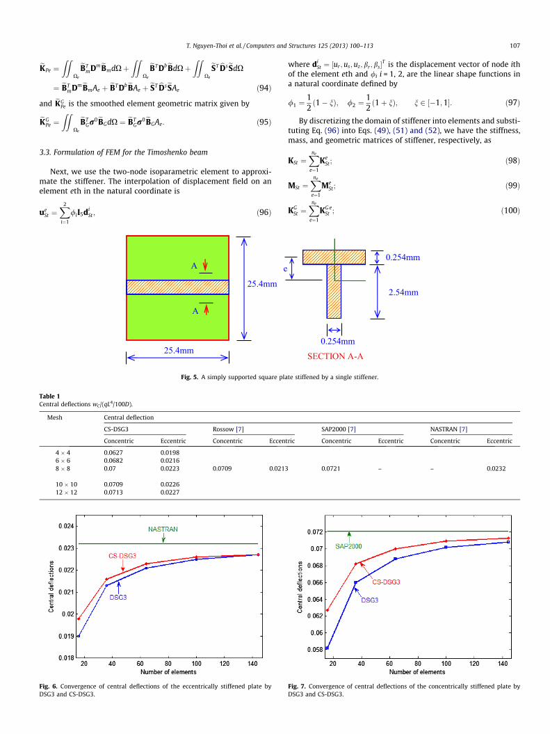
Fig. 5. A simply supported square pla
Table 1Central deflections wC/(qL4/100D).
Mesh Central deflection
CS-DSG3 Rossow [7]
Concentric Eccentric Concentric Eccent
4 � 4 0.0627 0.01986 � 6 0.0682 0.02168 � 8 0.07 0.0223 0.0709 0.0213
10 � 10 0.0709 0.022612 � 12 0.0713 0.0227
Fig. 6. Convergence of central deflections of the eccentrically stiffened plate byDSG3 and CS-DSG3.
where diSt ¼ ½ur ;us;uz; br; bs�
T is the displacement vector of node ithof the element eth and /i i = 1, 2, are the linear shape functions ina natural coordinate defined by
/1 ¼12ð1� nÞ; /2 ¼
12ð1þ nÞ; n 2 ½�1;1�: ð97Þ
By discretizing the domain of stiffener into elements and substi-tuting Eq. (96) into Eqs. (49), (51) and (52), we have the stiffness,mass, and geometric matrices of stiffener, respectively, as
KSt ¼Xne
e¼1
KeSt ; ð98Þ
MSt ¼Xne
e¼1
MeSt; ð99Þ
KGSt ¼
Xne
e¼1
KG eSt ; ð100Þ
te stiffened by a single stiffener.
SAP2000 [7] NASTRAN [7]
ric Concentric Eccentric Concentric Eccentric
0.0721 – – 0.0232
Fig. 7. Convergence of central deflections of the concentrically stiffened plate byDSG3 and CS-DSG3.
108 T. Nguyen-Thoi et al. / Computers and Structures 125 (2013) 100–113
where ne is the number of elements of stiffener, and the elementstiffness, mass, and geometric matrices, respectively, are computedby
KeSt ¼
ZlðLE
StUÞT DStLE
StUdl; ð101Þ
MeSt ¼
Zl
UT AT mStAUdl; ð102Þ
KG eSt ¼
ZlðLG
StUÞTr0
StLGStUdl: ð103Þ
3.4. Formulation of CS-DSG3 for the stiffened plate
We now apply the displacement conforming conditions toformulate the overall stiffness, mass, and geometric matrices ofthe stiffened plate. The displacement conforming conditions arestated as
dSt ¼ Td; ð104Þ
where T is the transform matrix as presented in [20], dSt is the nodaldisplacement vector of the stiffener and d is the nodal displacementvector of the stiffened plate.
Using Eqs. (73), (92), (93), (98)–(100) and (104), we have theoverall stiffness, mass, and geometric matrices for the stiffenedplate, respectively, aseK ¼ eKP þ TT KStT; ð105ÞeKG ¼ eKG
P þ TT KGStT; ð106Þ
M ¼MP þ TT MStT: ð107Þ
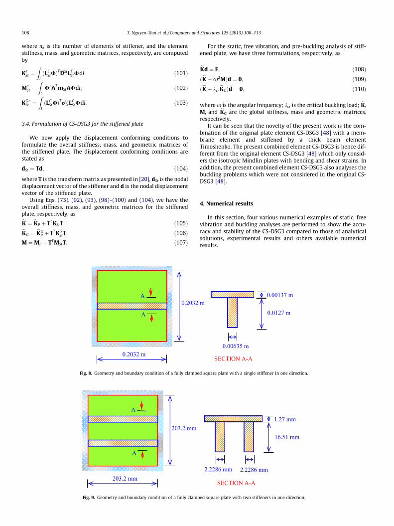
Fig. 8. Geometry and boundary condition of a fully clampe
Fig. 9. Geometry and boundary condition of a fully clamp
For the static, free vibration, and pre-buckling analysis of stiff-ened plate, we have three formulations, respectively, as
eKd ¼ F; ð108ÞðeK �x2MÞd ¼ 0; ð109ÞðeK � kcr
eKGÞd ¼ 0; ð110Þ
where x is the angular frequency; kcr is the critical buckling load; eK,M, and eKG are the global stiffness, mass and geometric matrices,respectively.
It can be seen that the novelty of the present work is the com-bination of the original plate element CS-DSG3 [48] with a mem-brane element and stiffened by a thick beam elementTimoshenko. The present combined element CS-DSG3 is hence dif-ferent from the original element CS-DSG3 [48] which only consid-ers the isotropic Mindlin plates with bending and shear strains. Inaddition, the present combined element CS-DSG3 also analyses thebuckling problems which were not considered in the original CS-DSG3 [48].
4. Numerical results
In this section, four various numerical examples of static, freevibration and buckling analyses are performed to show the accu-racy and stability of the CS-DSG3 compared to those of analyticalsolutions, experimental results and others available numericalresults.
d square plate with a single stiffener in one direction.
ed square plate with two stiffeners in one direction.
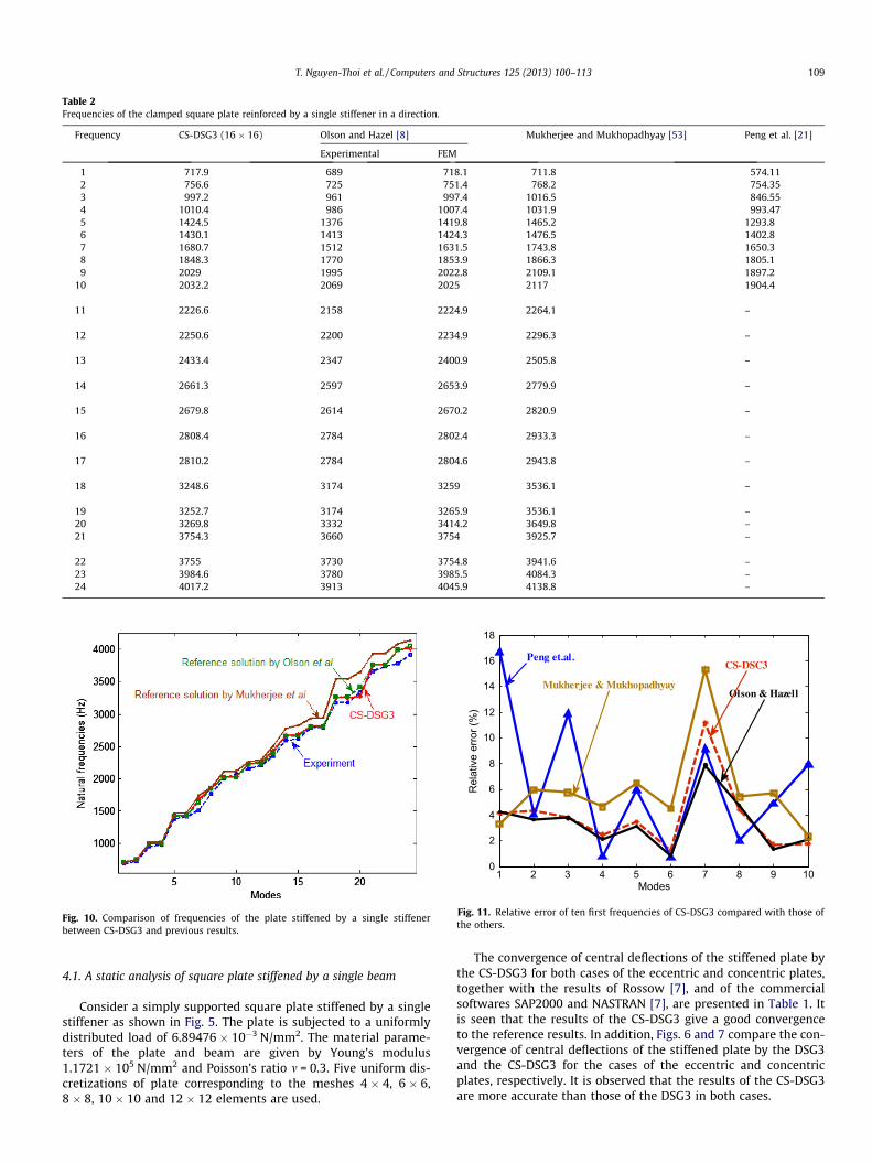
Table 2Frequencies of the clamped square plate reinforced by a single stiffener in a direction.
Frequency CS-DSG3 (16 � 16) Olson and Hazel [8] Mukherjee and Mukhopadhyay [53] Peng et al. [21]
Experimental FEM
1 717.9 689 718.1 711.8 574.112 756.6 725 751.4 768.2 754.353 997.2 961 997.4 1016.5 846.554 1010.4 986 1007.4 1031.9 993.475 1424.5 1376 1419.8 1465.2 1293.86 1430.1 1413 1424.3 1476.5 1402.87 1680.7 1512 1631.5 1743.8 1650.38 1848.3 1770 1853.9 1866.3 1805.19 2029 1995 2022.8 2109.1 1897.2
10 2032.2 2069 2025 2117 1904.4
11 2226.6 2158 2224.9 2264.1 –
12 2250.6 2200 2234.9 2296.3 –
13 2433.4 2347 2400.9 2505.8 –
14 2661.3 2597 2653.9 2779.9 –
15 2679.8 2614 2670.2 2820.9 –
16 2808.4 2784 2802.4 2933.3 –
17 2810.2 2784 2804.6 2943.8 –
18 3248.6 3174 3259 3536.1 –
19 3252.7 3174 3265.9 3536.1 –20 3269.8 3332 3414.2 3649.8 –21 3754.3 3660 3754 3925.7 –
22 3755 3730 3754.8 3941.6 –23 3984.6 3780 3985.5 4084.3 –24 4017.2 3913 4045.9 4138.8 –
Fig. 10. Comparison of frequencies of the plate stiffened by a single stiffenerbetween CS-DSG3 and previous results.
1 2 3 4 5 6 7 8 9 100
2
4
6
8
10
12
14
16
18
Modes
Rel
ativ
e er
ror (
%)
Peng et.al.
Olson & Hazell
CS-DSC3
Mukherjee & Mukhopadhyay
Fig. 11. Relative error of ten first frequencies of CS-DSG3 compared with those ofthe others.
T. Nguyen-Thoi et al. / Computers and Structures 125 (2013) 100–113 109
4.1. A static analysis of square plate stiffened by a single beam
Consider a simply supported square plate stiffened by a singlestiffener as shown in Fig. 5. The plate is subjected to a uniformlydistributed load of 6.89476 � 10�3 N/mm2. The material parame-ters of the plate and beam are given by Young’s modulus1.1721 � 105 N/mm2 and Poisson’s ratio m = 0.3. Five uniform dis-cretizations of plate corresponding to the meshes 4 � 4, 6 � 6,8 � 8, 10 � 10 and 12 � 12 elements are used.
The convergence of central deflections of the stiffened plate bythe CS-DSG3 for both cases of the eccentric and concentric plates,together with the results of Rossow [7], and of the commercialsoftwares SAP2000 and NASTRAN [7], are presented in Table 1. Itis seen that the results of the CS-DSG3 give a good convergenceto the reference results. In addition, Figs. 6 and 7 compare the con-vergence of central deflections of the stiffened plate by the DSG3and the CS-DSG3 for the cases of the eccentric and concentricplates, respectively. It is observed that the results of the CS-DSG3are more accurate than those of the DSG3 in both cases.
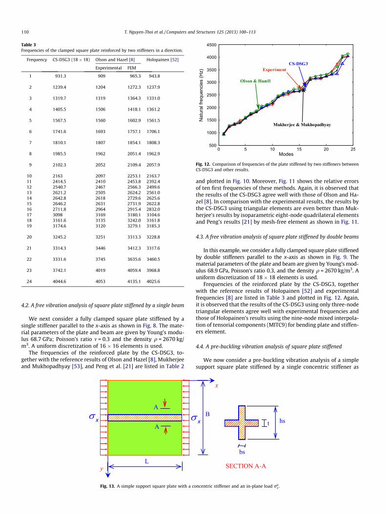
Table 3Frequencies of the clamped square plate reinforced by two stiffeners in a direction.
Frequency CS-DSG3 (18 � 18) Olson and Hazel [8] Holopainen [52]
Experimental FEM
1 931.3 909 965.3 943.8
2 1239.4 1204 1272.3 1237.9
3 1319.7 1319 1364.3 1331.0
4 1405.5 1506 1418.1 1361.2
5 1567.5 1560 1602.9 1561.5
6 1741.6 1693 1757.1 1706.1
7 1810.1 1807 1854.1 1808.3
8 1985.5 1962 2051.4 1962.9
9 2102.3 2052 2109.4 2057.9
10 2163 2097 2253.1 2163.711 2414.5 2410 2453.8 2392.412 2540.7 2467 2566.3 2499.613 2621.2 2505 2624.2 2561.014 2642.8 2618 2729.6 2625.615 2646.2 2631 2731.9 2622.816 2711.8 2964 2915.4 2832.017 3098 3169 3180.1 3104.618 3161.6 3135 3242.0 3161.819 3174.6 3120 3279.1 3185.3
20 3245.2 3251 3313.3 3228.8
21 3314.3 3446 3412.3 3317.6
22 3331.6 3745 3635.6 3460.5
23 3742.1 4019 4059.4 3968.8
24 4044.6 4053 4135.1 4025.6
Fig. 12. Comparison of frequencies of the plate stiffened by two stiffeners betweenCS-DSG3 and other results.
110 T. Nguyen-Thoi et al. / Computers and Structures 125 (2013) 100–113
4.2. A free vibration analysis of square plate stiffened by a single beam
We next consider a fully clamped square plate stiffened by asingle stiffener parallel to the x-axis as shown in Fig. 8. The mate-rial parameters of the plate and beam are given by Young’s modu-lus 68.7 GPa; Poisson’s ratio m = 0.3 and the density q = 2670 kg/m3. A uniform discretization of 16 � 16 elements is used.
The frequencies of the reinforced plate by the CS-DSG3, to-gether with the reference results of Olson and Hazel [8], Mukherjeeand Mukhopadhyay [53], and Peng et al. [21] are listed in Table 2
Fig. 13. A simple support square plate with a co
and plotted in Fig. 10. Moreover, Fig. 11 shows the relative errorsof ten first frequencies of these methods. Again, it is observed thatthe results of the CS-DSG3 agree well with those of Olson and Ha-zel [8]. In comparison with the experimental results, the results bythe CS-DSG3 using triangular elements are even better than Muk-herjee’s results by isoparametric eight-node quadrilateral elementsand Peng’s results [21] by mesh-free element as shown in Fig. 11.
4.3. A free vibration analysis of square plate stiffened by double beams
In this example, we consider a fully clamped square plate stiffenedby double stiffeners parallel to the x-axis as shown in Fig. 9. Thematerial parameters of the plate and beam are given by Young’s mod-ulus 68.9 GPa, Poisson’s ratio 0.3, and the density q = 2670 kg/m3. Auniform discretization of 18� 18 elements is used.
Frequencies of the reinforced plate by the CS-DSG3, togetherwith the reference results of Holopainen [52] and experimentalfrequencies [8] are listed in Table 3 and plotted in Fig. 12. Again,it is observed that the results of the CS-DSG3 using only three-nodetriangular elements agree well with experimental frequencies andthose of Holopainen’s results using the nine-node mixed interpola-tion of tensorial components (MITC9) for bending plate and stiffen-ers element.
4.4. A pre-buckling vibration analysis of square plate stiffened
We now consider a pre-buckling vibration analysis of a simplesupport square plate stiffened by a single concentric stiffener as
ncentric stiffener and an in-plane load r0x .
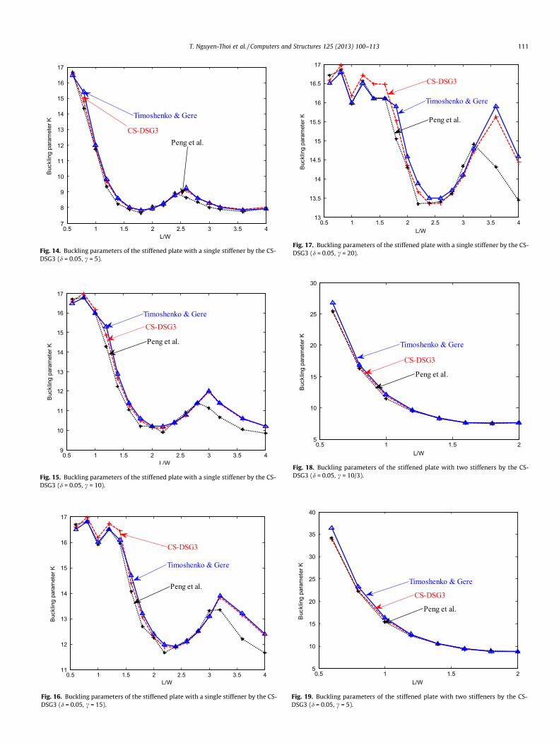
Fig. 14. Buckling parameters of the stiffened plate with a single stiffener by the CS-DSG3 (d = 0.05, c = 5).
Fig. 15. Buckling parameters of the stiffened plate with a single stiffener by the CS-DSG3 (d = 0.05, c = 10).
Fig. 16. Buckling parameters of the stiffened plate with a single stiffener by the CS-DSG3 (d = 0.05, c = 15).
Fig. 17. Buckling parameters of the stiffened plate with a single stiffener by the CS-DSG3 (d = 0.05, c = 20).
Fig. 18. Buckling parameters of the stiffened plate with two stiffeners by the CS-DSG3 (d = 0.05, c = 10/3).
Fig. 19. Buckling parameters of the stiffened plate with two stiffeners by the CS-DSG3 (d = 0.05, c = 5).
T. Nguyen-Thoi et al. / Computers and Structures 125 (2013) 100–113 111
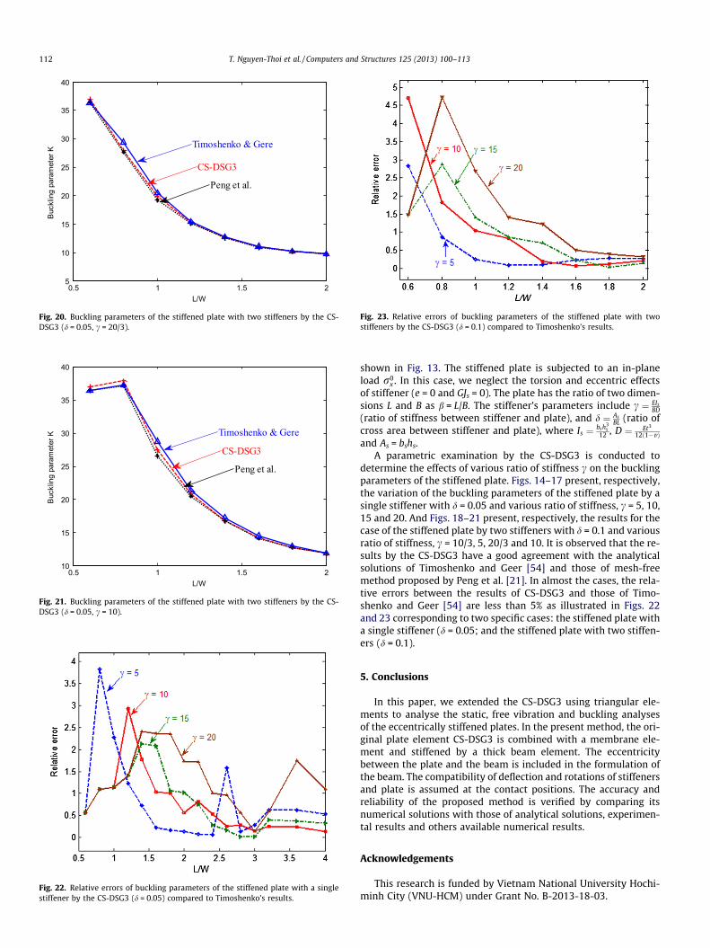
Fig. 20. Buckling parameters of the stiffened plate with two stiffeners by the CS-DSG3 (d = 0.05, c = 20/3).
Fig. 21. Buckling parameters of the stiffened plate with two stiffeners by the CS-DSG3 (d = 0.05, c = 10).
Fig. 22. Relative errors of buckling parameters of the stiffened plate with a singlestiffener by the CS-DSG3 (d = 0.05) compared to Timoshenko’s results.
Fig. 23. Relative errors of buckling parameters of the stiffened plate with twostiffeners by the CS-DSG3 (d = 0.1) compared to Timoshenko’s results.
112 T. Nguyen-Thoi et al. / Computers and Structures 125 (2013) 100–113
shown in Fig. 13. The stiffened plate is subjected to an in-planeload r0
x . In this case, we neglect the torsion and eccentric effectsof stiffener (e = 0 and GJs = 0). The plate has the ratio of two dimen-sions L and B as b = L/B. The stiffener’s parameters include c ¼ EIs
BD(ratio of stiffness between stiffener and plate), and d ¼ As
BL (ratio ofcross area between stiffener and plate), where Is ¼ bsh3
s12 , D ¼ Et3
12ð1�vÞand As = bshs.
A parametric examination by the CS-DSG3 is conducted todetermine the effects of various ratio of stiffness c on the bucklingparameters of the stiffened plate. Figs. 14–17 present, respectively,the variation of the buckling parameters of the stiffened plate by asingle stiffener with d = 0.05 and various ratio of stiffness, c = 5, 10,15 and 20. And Figs. 18–21 present, respectively, the results for thecase of the stiffened plate by two stiffeners with d = 0.1 and variousratio of stiffness, c = 10/3, 5, 20/3 and 10. It is observed that the re-sults by the CS-DSG3 have a good agreement with the analyticalsolutions of Timoshenko and Geer [54] and those of mesh-freemethod proposed by Peng et al. [21]. In almost the cases, the rela-tive errors between the results of CS-DSG3 and those of Timo-shenko and Geer [54] are less than 5% as illustrated in Figs. 22and 23 corresponding to two specific cases: the stiffened plate witha single stiffener (d = 0.05; and the stiffened plate with two stiffen-ers (d = 0.1).
5. Conclusions
In this paper, we extended the CS-DSG3 using triangular ele-ments to analyse the static, free vibration and buckling analysesof the eccentrically stiffened plates. In the present method, the ori-ginal plate element CS-DSG3 is combined with a membrane ele-ment and stiffened by a thick beam element. The eccentricitybetween the plate and the beam is included in the formulation ofthe beam. The compatibility of deflection and rotations of stiffenersand plate is assumed at the contact positions. The accuracy andreliability of the proposed method is verified by comparing itsnumerical solutions with those of analytical solutions, experimen-tal results and others available numerical results.
Acknowledgements
This research is funded by Vietnam National University Hochi-minh City (VNU-HCM) under Grant No. B-2013-18-03.
T. Nguyen-Thoi et al. / Computers and Structures 125 (2013) 100–113 113
References
[1] Ramakrishnan R, Kunukkaseril VX. Free vibration of stiffened circular bridgedeck. J Sound Vib 1976;44:209–21.
[2] Mukhopadhyay M. A semi-analytic solution for free vibration of rectangularplates. J Sound Vib 1978;60(l):71–85.
[3] Mukhopadhyay M. Vibration and stability analysis of stiffened plates by semi-analytic finite difference method. Part I: consideration of bendingdisplacements only. J Sound Vib 1989;130(1):27–39.
[4] Mukhopadhyay M. Vibration and stability analysis of stiffened plates by semi-analytic finite difference method. Part II: consideration of bending and axialdisplacements. J Sound Vib 1989;130(1):41–53.
[5] Mukhopadhyay M. Stiffened plates in bending. Comput Struct 1994;50(4):541–8.
[6] Chan HC, Cai CW, Cheung YK. A static solution of stiffened plates. Thin-WalledStruct 1991;11:291–303.
[7] Rossow MP, Ibrahimkhail AK. Constraint method analysis of stiffened plates.Comput Struct 1978;8:51–60.
[8] Olson MD, Hazel CR. Vibration studies on some integral rib stiffened plates. JSound Vib 1977;50:43–61.
[9] Barik M. Finite element static, dynamic and stability analyses of arbitrarystiffened plates. PhD thesis, Indian Institute of Technology, Kharapur, 1999.
[10] Barik M, Mukhopadhyay M. A new stiffened plate element for the analysis ofarbitrary plates. Thin-Walled Struct 2002;40:625–39.
[11] Deb A, Booton M. Finite element models for stiffened plates under transverseload. Comput Struct 1988;28(3):361–72.
[12] Mukheriee A, Mukhoadhyay M. Finite element free vibration of eccentricallystiffened plates. Comput Struct 1988;30:1303–17.
[13] Mukheriee A, Mukhoadhyay M. Finite element buckling analysis of stiffenedplates. Comput Struct 1990;34:795–803.
[14] Zienkiewicz OC, Taylor RL. The finite element method. Solid mechanics, 5thed., vol. 2. Butterworth-Heinemann; 2000.
[15] Palani GS, Iyer NR, Appa Rao TVSR. An efficient finite element model for staticand vibration analysis of eccentrically stiffened plates/shells. Comput Struct1992;43(4):651–61.
[16] Holopainen TP. Finite element free vibration analysis of eccentrically stiffenedplates. Comput Struct 1995;56:993–1007.
[17] Liew KM, Xiang Y, Kitipornchai S, Lim MK. Vibration of rectangular Mindlin plateswith intermediate stiffeners. Trans ASME J Vib Acoust 1994;116:529–35.
[18] Xiang Y, Kitipornchai S, Liew KM, Lim MK. Vibration of stiffened skew Mindlinplates. Acta Mech 1995;112:11–28.
[19] Liew KM, Xiang Y, Kitipornchai S, Meek JL. Formulation of Mindlin–Engessermodel for stiffened plate vibration. Comput Methods Appl Mech Eng1995;120:339–53.
[20] Peng LX, Kitipornchai S, Liew KM. Analysis of rectangular stiffened platesunder uniform lateral load based on FSDT and element-free Galerkin method.Int J Mech Sci 2005;47:251–76.
[21] Peng LX, Liew KM, Kitipornchai S. Buckling and free vibration analyses of stiffenedplates using the FSDT mesh-free method. J Sound Vib 2006;289:421–49.
[22] Peng LX, Liew KM, Kitipornchai S. Analysis of stiffened corrugated plates basedon the FSDT via the mesh-free method. Int J Mech Sci 2007;49:364–78.
[23] Liew KM, Xiang Y, Kitipornchai S. Research on thick plate vibration: a literaturesurvey. J Sound Vib 1995;180(1):163–76.
[24] Satsangi SK. An investigation of stiffened plate panels using isoparametricplate bending elements. PhD thesis, Indian Institute of Technology, Kharagpur1985.
[25] Satsangi SK, Mukhoadhyay M. A review of static analysis of stiffened plates. JStruct Eng 1989;15:117–26.
[26] Chen JS, Wu CT, Yoon S, You Y. A stabilized conforming nodal integration forGalerkin mesh-free methods. Int J Numer Methods Eng 2001;50:435–66.
[27] Liu GR, Nguyen-Thoi Trung. Smoothed finite element methods. NewYork: CRCPress, Taylor and Francis Group; 2010.
[28] Liu GR, Dai KY, Nguyen-Thoi T. A smoothed finite element for mechanicsproblems. Comput Mech 2007;39:859–77.
[29] Liu GR, Nguyen-Thoi T, Nguyen-Xuan H, Lam KY. A node-based smoothedfinite element method (NS-FEM) for upper bound solutions to solid mechanicsproblems. Comput Struct 2009;87:14–26.
[30] Liu GR, Nguyen-Thoi T, Lam KY. An edge-based smoothed finite elementmethod (ES-FEM) for static and dynamic problems of solid mechanics. J SoundVib 2009;32:1100–30.
[31] Nguyen-Thoi T, Liu GR, Lam KY, Zhang GY. A face-based smoothed finiteelement method (FS-FEM) for 3D linear and nonlinear solid mechanicsproblems using 4-node tetrahedral elements. Int J Numer Methods Eng2009;78:324–53.
[32] Liu GR, Nguyen-Thoi T, Dai KY, Lam KY. Theoretical aspects of the smoothedfinite element method (SFEM). Int J Numer Methods Eng 2007;71:902–30.
[33] Liu GR, Nguyen-Xuan H, Nguyen-Thoi T. A theoretical study on NS/ES-FEM:properties, accuracy and convergence rates. Int J Numer Methods Eng2010;84:1222–56.
[34] Nguyen-Xuan H, Nguyen-Thoi T. A stabilized smoothed finite element methodfor free vibration analysis of Mindlin–Reissner plates. Int J Numer MethodsBiomed Eng 2009;25:882–906.
[35] Nguyen-Xuan H, Liu GR, Thai-Hoang C, Nguyen-Thoi T. An edge-basedsmoothed finite element method with stabilized discrete shear gaptechnique for analysis of Reissner–Mindlin plates. Comput Methods ApplMech Eng 2009;199:471–89.
[36] Cui XY, Liu GR, Li GY. Analysis of Mindlin–Reissner plates using cell-basedsmoothed radial point interpolation method. Int J Appl Mech2010;2(3):653–80.
[37] Cui XY, Liu GR, Li GY, Zao X, Nguyen-Thoi T, Sun GY. A smoothed finite elementmethod (SFEM) for linear and geometrically nonlinear analysis of plates andshells. CMES – Computer Model Eng Sci 2008;28(2):109–25.
[38] Cui XY, Liu GR, Li GY, Zeng G. A rotation free formulation for static and freevibration analysis of thin beams using gradient smoothing technique. CMES –Computer Model Eng Sci 2008;38(3):217–29.
[39] Cui XY, Liu GR, Li GY. A smoothed hermite radial point interpolation methodfor thin plate analysis. Arch Appl Mech 2011;81(1):1–18.
[40] Cui XY, Liu GR, Li GY, Zang GY, Zeng G. Analysis of plates and shells using anedge-based smoothed finite element method. Comput Mech 2010;45(2–3):141–56.
[41] Cui XY, Liu GR, Li GY. Bending and vibration responses of laminated compositeplates using an edge-based smoothing technique. Eng Anal Boundary Elem2011;35(6):818–26.
[42] Nguyen-Xuan H, Liu GR, Nguyen-Thoi T, Nguyen-Tran C. An edge-basedsmoothed finite element method (ES-FEM) for analysis of two-dimensionalpiezoelectric structures. Smart Mater Struct 2009;18:1–11.
[43] Liu GR, Chen L, Nguyen-Thoi T, Zeng K, Zhang GY. A novel singular node-basedsmoothed finite element method (NS-FEM) for upper bound solutions ofcracks. Int J Numer Methods Eng 2010;83(11):1466–97.
[44] Cui XY, Liu GR, Li GY, Zang GY, Sun GY. Analysis of elastic-plastic problemsusing edge-based smoothed finite element method. Int J Press Vessels Pip2009;86(10):711–8.
[45] Nguyen-Thoi T, Liu GR, Vu-Do HC, Nguyen-Xuan H. An edge-based smoothedfinite element method (ES-FEM) for visco-elastoplastic analyses of 2D solidsusing triangular mesh. Comput Mech 2009;45:23–44.
[46] Nguyen-Thoi T, Liu GR, Vu-Do HC, Nguyen-Xuan H. A face-based smoothedfinite element method (FS-FEM) for visco-elastoplastic analyses of 3D solidsusing tetrahedral mesh. Comput Methods Appl Mech Eng 2009;198:3479–98.
[47] Tran TN, Liu GR, Nguyen-Xuan H, Nguyen-Thoi T. An edge-based smoothedfinite element method for primal-dual shakedown analysis of structures. Int JNumer Methods Eng 2010;82:917–38.
[48] Nguyen-Thoi T, Phung-Van P, Nguyen-Xuan H, Thai-Hoang C. A cell-basedsmoothed discrete shear gap method using triangular elements for static andfree vibration analyses of Reissner–Mindlin plates. Int J Numer Methods Eng2012;91(7):705–41.
[49] Bletzinger KU, Bischoff M, Ramm E. A unified approach for shear-locking freetriangular and rectangular shell finite elements. Comput Struct2000;75:321–34.
[50] Bischoff M, Bletzinger KU. Stabilized DSG plate and shell elements. Trends incomputational structural mechanics. CIMNE, Barcelona, Spain, 2001.
[51] Thai-Hoang Chien, Nguyen-Thanh Nhon, Nguyen-Xuan Hung, Timon Rabczuk,Stephane Bordas. A cell-based smoothed finite element method for freevibration and buckling analysis of shells. KSCE J Civil Eng 2011;15(2):347–61.
[52] Holopainen TP. Finite element free vibration analysis of eccentrically stiffenedplates. Comput Struct 1995;56:993–1010.
[53] Mukherjee A, Mukhopadhyay M. Finite element free vibration of eccentricallystiffened plates. Comput Struct 1988;30:1303–17.
[54] Timoshenko SP, Gere JM. Theory of elastic stability. New York: McGraw-Hill;1961.
Related Documents