HAL Id: hal-00538003 https://hal.archives-ouvertes.fr/hal-00538003 Submitted on 20 Nov 2010 HAL is a multi-disciplinary open access archive for the deposit and dissemination of sci- entific research documents, whether they are pub- lished or not. The documents may come from teaching and research institutions in France or abroad, or from public or private research centers. L’archive ouverte pluridisciplinaire HAL, est destinée au dépôt et à la diffusion de documents scientifiques de niveau recherche, publiés ou non, émanant des établissements d’enseignement et de recherche français ou étrangers, des laboratoires publics ou privés. Static and fatigue failure of quasi brittle materials at a V-notch using a Dugdale model S. Murer, Dominique Leguillon To cite this version: S. Murer, Dominique Leguillon. Static and fatigue failure of quasi brittle materials at a V-notch using a Dugdale model. European Journal of Mechanics - A/Solids, Elsevier, 2009, 29 (2), pp.109. 10.1016/j.euromechsol.2009.10.005. hal-00538003

Welcome message from author
This document is posted to help you gain knowledge. Please leave a comment to let me know what you think about it! Share it to your friends and learn new things together.
Transcript
HAL Id: hal-00538003https://hal.archives-ouvertes.fr/hal-00538003
Submitted on 20 Nov 2010
HAL is a multi-disciplinary open accessarchive for the deposit and dissemination of sci-entific research documents, whether they are pub-lished or not. The documents may come fromteaching and research institutions in France orabroad, or from public or private research centers.
L’archive ouverte pluridisciplinaire HAL, estdestinée au dépôt et à la diffusion de documentsscientifiques de niveau recherche, publiés ou non,émanant des établissements d’enseignement et derecherche français ou étrangers, des laboratoirespublics ou privés.
Static and fatigue failure of quasi brittle materials at aV-notch using a Dugdale model
S. Murer, Dominique Leguillon
To cite this version:S. Murer, Dominique Leguillon. Static and fatigue failure of quasi brittle materials at a V-notchusing a Dugdale model. European Journal of Mechanics - A/Solids, Elsevier, 2009, 29 (2), pp.109.�10.1016/j.euromechsol.2009.10.005�. �hal-00538003�

Accepted Manuscript
Title: Static and fatigue failure of quasi brittle materials at a V-notch using a Dugdalemodel
Authors: S. Murer, D. Leguillon
PII: S0997-7538(09)00122-3
DOI: 10.1016/j.euromechsol.2009.10.005
Reference: EJMSOL 2557
To appear in: European Journal of Mechanics / A Solids
Received Date: 14 May 2009
Revised Date: 9October2009
Accepted Date: 16 October 2009
Please cite this article as: Murer, S., Leguillon, D. Static and fatigue failure of quasi brittle materialsat a V-notch using a Dugdale model, European Journal of Mechanics / A Solids (2009), doi: 10.1016/j.euromechsol.2009.10.005
This is a PDF file of an unedited manuscript that has been accepted for publication. As a service toour customers we are providing this early version of the manuscript. The manuscript will undergocopyediting, typesetting, and review of the resulting proof before it is published in its final form. Pleasenote that during the production process errors may be discovered which could affect the content, and alllegal disclaimers that apply to the journal pertain.
MANUSCRIP
T
ACCEPTED
ARTICLE IN PRESS
Static and fatigue failure of quasi brittle materials at a V-notch using a Dugdale model
S. Murer1 and D. Leguillon1*
1 Institut Jean le Rond d’Alembert - CNRS UMR 7190
Université Pierre et Marie Curie - Paris 6 4 place Jussieu, case 162, 75252 Paris Cedex 05 – France
Tel.: +33 144 275 322 Fax: +33 144 275 259 [email protected]
* Corresponding author Running title: Static and fatigue failure Abstract The prediction of crack nucleation at stress concentration points in brittle and quasi-brittle materials may generally rely on either an Irwin-like criterion, involving a critical value of the generalized stress intensity factor of the singularity associated to the stress concentration, or on cohesive zone models. Leguillon’s criterion enters the first category and combines an energy condition and a stress one. Thanks to matched asymptotics procedures, the associated numerical values at crack initiation under quasi-static monotonic loadings are shown to be comparable to those obtained using the Dugdale cohesive zone model. Both approaches are therefore adapted to the description of brittle and quasi-brittle fracture. A macroscopic Paris-like propagation law is derived from the Dugdale model through a relevant cumulating law at the microscopic scale of the process zone. Comparisons with experimental results are performed and display good agreement. The important matter of nucleation and growth of a fatigue crack at the root of a V-notch is finally addressed. A general Paris law featuring the elastic singularity exponent and then dependent on the V-notch angle can be expressed for small cyclic loadings in the early growth stage. Keywords: quasi-brittle materials, failure criterion, cohesive zone model, static loading, fatigue loading, Paris law. 1. Introduction The brittle fracture theory (Lawn 1993) deals with the conditions of propagation of a pre-existing crack in brittle and quasi-brittle materials, but it is unable to address the emergence of a new crack at a stress concentration point like a V-notch root. Many efforts have been made to answer this question with a general criterion without going into the details of micro mechanisms. Two approaches can be highlighted, one goes through a non-local criterion and enters a general theoretical context while the other uses the cohesive zone models

MANUSCRIP
T
ACCEPTED
ARTICLE IN PRESS
which have been developed and are more often used in a computational structures background. These two approaches share a common feature, they require two failure parameters to choose among the following three: the material toughness denoted either cG (J.m-2) or IcK (MPa.m1/2), the tensile strength cσ (MPa) and a characteristic length cl (m). Within the non local approach, a first family is based on a point-stress condition (Mc Clintock 1958, Leguillon 2002, Leguillon, Yosibash 2003, Taylor 2008): failure occurs if the tensile stress exceeds a given critical value at a given distance of the V-notch root. Leguillon’s criterion enters this family but the critical distance is no longer a material property, it depends on the local geometry. Its definition relies on an energy balance equation in addition to the maximum tensile stress condition (Leguillon 2002). This approach is naturally extended to the average stress criterion: failure occurs if the tensile stress averaged on a given distance exceeds a given critical value (Novozhilov 1969, Seweryn 1994, Seweryn, Mroz 1998, Seweryn, Lukaszewicz 2002). The stress condition is generally transcribed into a condition on the generalized stress intensity factor (GSIF) characterizing the influence of the singular field associated with the V-notch, leading to an Irwin-like criterion. A second family is based on the strain energy density concept, failure occurs if the strain energy density (SED) exceeds a given value over a given volume (Sih 1973, Yosibash et al. 2004) encompassing the stress concentration point. This second approach is generally less accurate. After the pioneering works of Dugdale (1960) and Barenblatt (1962), the cohesive zone models (Tvergaard, Hutchinson 1992, Planas, Elices 1992-1993, Xu, Needleman 1994, Bazant, Planas 1998) were originally developed for studying the fracture of interfaces in heterogeneous materials and particularly the mechanisms of delamination in composite laminates (Needleman 1990, Allix, Ladeveze 1992, Mi et al. 1998, Alfano, Crisfield 2001). They model a process zone ahead of the crack tip or the stress concentration point. In this zone the material yields or damages but cohesive forces still act until the final fracture. Different profiles of the force/opening curve are proposed by authors (Alfano 2006), they are characterized either by a peak stress and a critical opening or by a peak stress and a fracture energy corresponding to the surface located below the curve. All these approaches are in general dedicated to quasi-static monotonic loadings; the literature becomes sparse when looking at the effects of fatigue loads in the vicinity of stress concentration points in quasi-brittle materials. Most of the papers agree to recognize that the GSIF is a relevant parameter at least to describe the appearance of short cracks, i.e. the life time at initiation (Taylor 1999, Atzori et al. 2002-2003, Lazzarin et al. 2003, Madi et al; 2004, Livieri, Lazzarin 2005), although some others prefer using the SED (Lazzarin, Zambardi 2001). The influence of the blunting of the V-notch is taken into account by a modified GSIF according to a parameter called the notch acuity (Boukharouba et al. 1995). Anyway these papers focus on different points like the fatigue strength presenting Kitagawa-Takahashi diagrams, the life time at initiation and the total life time assessments through S-N and Manson-Coffin curves, but none mentions the influence of the V-notch on a propagation law of Paris type. In a broader context, we find the coupling between a cohesive law and a fatigue loading in different papers which share the same point of view. The damage irreversibility is obtained from a complementary mechanism to the cohesive law: a hysteresis due to different loading and unloading paths (Nguyen et al. 2001, Yang et al. 2001, Maiti, Geubelle 2005, Bouvard et al. 2009, Ural et al. 2009).
MANUSCRIP
T
ACCEPTED
ARTICLE IN PRESS
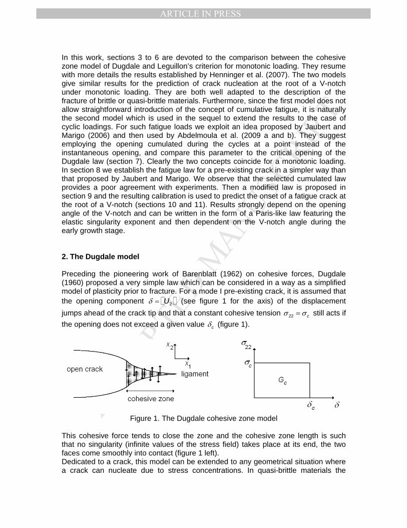
In this work, sections 3 to 6 are devoted to the comparison between the cohesive zone model of Dugdale and Leguillon’s criterion for monotonic loading. They resume with more details the results established by Henninger et al. (2007). The two models give similar results for the prediction of crack nucleation at the root of a V-notch under monotonic loading. They are both well adapted to the description of the fracture of brittle or quasi-brittle materials. Furthermore, since the first model does not allow straightforward introduction of the concept of cumulative fatigue, it is naturally the second model which is used in the sequel to extend the results to the case of cyclic loadings. For such fatigue loads we exploit an idea proposed by Jaubert and Marigo (2006) and then used by Abdelmoula et al. (2009 a and b). They suggest employing the opening cumulated during the cycles at a point instead of the instantaneous opening, and compare this parameter to the critical opening of the Dugdale law (section 7). Clearly the two concepts coincide for a monotonic loading. In section 8 we establish the fatigue law for a pre-existing crack in a simpler way than that proposed by Jaubert and Marigo. We observe that the selected cumulated law provides a poor agreement with experiments. Then a modified law is proposed in section 9 and the resulting calibration is used to predict the onset of a fatigue crack at the root of a V-notch (sections 10 and 11). Results strongly depend on the opening angle of the V-notch and can be written in the form of a Paris-like law featuring the elastic singularity exponent and then dependent on the V-notch angle during the early growth stage. 2. The Dugdale model Preceding the pioneering work of Barenblatt (1962) on cohesive forces, Dugdale (1960) proposed a very simple law which can be considered in a way as a simplified model of plasticity prior to fracture. For a mode I pre-existing crack, it is assumed that the opening component 2Uδ = (see figure 1 for the axis) of the displacement jumps ahead of the crack tip and that a constant cohesive tension 22 cσ σ= still acts if the opening does not exceed a given value cδ (figure 1).
Figure 1. The Dugdale cohesive zone model
This cohesive force tends to close the zone and the cohesive zone length is such that no singularity (infinite values of the stress field) takes place at its end, the two faces come smoothly into contact (figure 1 left). Dedicated to a crack, this model can be extended to any geometrical situation where a crack can nucleate due to stress concentrations. In quasi-brittle materials the
MANUSCRIP
T
ACCEPTED
ARTICLE IN PRESS
cohesive peak force cσ is chosen as the tensile strength of the material. In order to match the Griffith theory, the surface below the curve must equal the toughness cG (figure 1). The result is a relationship between the three parameters (Bazant, Planas 1998)
cc
c
Gδ
σ= (1)
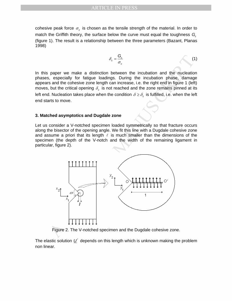
In this paper we make a distinction between the incubation and the nucleation phases, especially for fatigue loadings. During the incubation phase, damage appears and the cohesive zone length can increase, i.e. the right end in figure 1 (left) moves, but the critical opening cδ is not reached and the zone remains pinned at its left end. Nucleation takes place when the condition cδ δ≥ is fulfilled, i.e. when the left end starts to move. 3. Matched asymptotics and Dugdale zone Let us consider a V-notched specimen loaded symmetrically so that fracture occurs along the bisector of the opening angle. We fit this line with a Dugdale cohesive zone and assume a priori that its length l is much smaller than the dimensions of the specimen (the depth of the V-notch and the width of the remaining ligament in particular, figure 2).
Figure 2. The V-notched specimen and the Dugdale cohesive zone.
The elastic solution lU depends on this length which is unknown making the problem non linear.

MANUSCRIP
T
ACCEPTED
ARTICLE IN PRESS
0
0
. in (balance)
: in (constitutive law)
. on the upper and lower faces of the specimen
. on the two faces of the cohesive zone
. elsewhere on the boundary
x
x
c
U
n F
n
n
σ
σ
σ
σ σ
σ
⎧−∇ = Ω⎪⎪ = ∇ Ω⎪⎪
=⎨⎪
= −⎪⎪
=⎪⎩
l l
l l l
l
l
l
C
(2)
where Ωl is the domain embedding the cohesive zone. The notation x∇ stands for the gradient operator with respect to the space variables ix , C is the stiffness matrix, F is the tensile load applied on the upper and lower parts of the specimen and cσ is the cohesive force acting on the two faces of the cohesive zone with length l . At this step, it is assumed that the opening at the end O does not exceed its critical value
/c c cGδ σ= . The solution to eqns. (2) can be expanded as follows (so called outer expansion) 0
1 2 1 2( , ) ( , ) small correctionU x x U x x= +l (3) where 0U is solution to the same problem but neglecting the small cohesive zone (i.e. 0→l leading to the unperturbed domain Ω0 ).
0 0
0 0 0
0
. 0 in (balance)
: in (constitutive law)
. on the upper and lower faces of the specimen
. 0 elsewhere on the boundary
x
xU
n F
n
σ
σ
σ
σ
⎧−∇ = Ω⎪⎪ = ∇ Ω⎪⎨
=⎪⎪
=⎪⎩l
C (4)
Eqn. (3) is a good approximation except in the close vicinity of the V-notch root. For more details in this area, we stretch the space variables /i iy x= l , so that the cohesive zone has now a dimensionless fixed length equal to 1 in the domain spanned by the iy ’s (figure 2). As →l 0 the stretched domain Ωin becomes
unbounded and the solution U l must fulfil the set of equations
. 0 in (balance)
: in (constitutive law)
. on the two faces of the cohesive zone
. 0 on the two faces of the V-notch
prescribed behaviour at infinity
iny
iny
c
U
n
n
σ
σ
σ σ
σ
⎧−∇ = Ω⎪⎪ = ∇ Ω⎪⎪⎨ = −⎪⎪ =⎪
+⎪⎩
l
l l
l
l
%
%
% l
%
C (5)

MANUSCRIP
T
ACCEPTED
ARTICLE IN PRESS
Here the notation y∇ stands for the gradient operator with respect to the stretched dimensionless space variables iy . The remote boundary conditions (eqn. (2)3) disappear and are replaced by a condition at infinity which remains to be defined. By superposition, the above problem splits into two parts called A and B
. 0 in (balance)
: in (constitutive law)
. 0 on the two faces of the cohesive zone
. 0 on the two faces of the V-notch
prescribed behaviour at infinity
A iny
A A iny
A
A
U
n
n
σ
σ
σ
σ
⎧−∇ = Ω⎪⎪ = ∇ Ω⎪⎪⎨ =⎪⎪ =⎪
+⎪⎩
%
%
%
%
C (6)
σ
σ
σ σ
σ
⎧−∇ = Ω⎪⎪ = ∇ Ω⎪⎪⎨ = −⎪⎪ =⎪
+⎪⎩
%
%
% l
%
. 0 in (balance)
: in (constitutive law)
. on the two faces of the cohesive zone
. 0 on the two faces of the V-notch
vanishing condition at infinity
B iny
B B iny
Bc
B
U
n
n
C (7)
where AU and BU depend on the iy ’s and in addition BU linearly depends on l . In problem A, it must be pointed out that, due to the stress free conditions, the cohesive zone plays the role of a crack. A similar interpretation can be given to the second problem, the crack is subjected to a “negative” pressure on both faces. The missing conditions at infinity in problem A are derived from a matching rule. Since BU vanishes at infinity, the behaviour of AU when y yρ = + →∞2 2
1 2 must
match the behaviour of 0U in the vicinity of the origin O located at the notch root (i.e.
when r x x= + →2 21 2 0 ). In the vicinity of a re-entrant corner, it is known that 0U has
a singular behaviour (Leguillon, Sanchez-Palencia 1987) and expands as ( , ) ( ) ( ) ... ( ) ( ) ...0 0 0
1 2U x x U O k r u U O k uλ λ λθ ρ θ= + + = + +l (8) where r and θ are the polar coordinates emanating from O and /rρ = l . The exponent λ ( / λ≤ ≤1 2 1) and the angular function ( )θu are the singular exponent and the associated mode. They only depend on the opening angle ω , in particular they are independent of the global geometry of the specimen and of the applied load. The weight k (MPa.m1-λ) is the generalized stress intensity factor (GSIF). It is proportional to the intensity of the applied load and coincides with the usual stress intensity factor (SIF) in case of a crack. Remark 1: The singular modes are normalized so that the tensile component of the stress field along the bisector is 1
22 1/ r λσ −= . For a crack this normalization is usually

MANUSCRIP
T
ACCEPTED
ARTICLE IN PRESS
22 1/ 2 rσ π= , thus in this particular case the present value of the SIF differs from the
usual one by a multiplier 2π . Finally eqns. (6) to (8) and the matching rule lead to an expansion (so-called inner expansion) ( , ) ( , ) ( ) ( , ) ( , ) ...0
1 2 1 2 1 2 1 2A B
cU x x U y y U O k V y y V y yλ σ= = + + +l ll l l l (9)
where AV and BV (MPa-1) are solutions to problems derived from eqns. (6) and (7) (the notation σ% is kept without confusion)
.
:
.
.
( )
0 in (balance)
in (constitutive law)
0 on the two faces of the cohesive zone
0 on the two faces of the V-notch
at infinity ( means "behaves like")
A iny
A A iny
A
A
A
V
n
n
V uλ
σ
σ
σ
σ
ρ θ
⎧−∇ = Ω⎪
= ∇ Ω⎪⎪
=⎨⎪
=⎪⎪ ≈ ≈⎩
%
%
%
%
C (10)
. 0 in (balance)
: in (constitutive law)
. 1 on the two faces of the cohesive zone
. 0 on the two faces of the V-notch
0 at infinity
B iny
B B iny
B
B
B
V
n
n
V
σ
σ
σ
σ
⎧−∇ = Ω⎪⎪ = ∇ Ω⎪⎪
=⎨⎪
=⎪⎪
≈⎪⎩
%
%
%
%
C
(11)
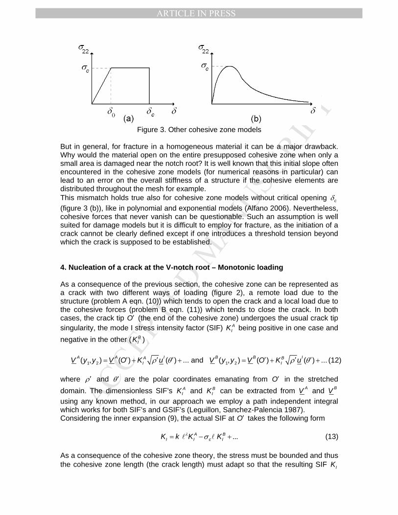
The functions AV and BV are computed once and for all for each opening value ω by finite elements, the infinite domain inΩ being artificially bounded at a large distance from the origin ( 200R = which is large compared to 1 i.e. to the cohesive zone dimensionless size). Obviously, this asymptotic approach only works for cohesive zone models featuring a threshold. An elastic slope for small openings (figure 3 (a)) is incompatible with the assumption of smallness of the cohesive zone length made here. Such a line spring model can be used to simulate a thin low stiffness adhesive layer for instance; the thickness is neglected and replaced by a displacement jump defined by the cohesive law and it is true all along the layer. The slope relies on the stiffness and the thickness of the layer (Rose 1987).
MANUSCRIP
T
ACCEPTED
ARTICLE IN PRESS
Figure 3. Other cohesive zone models
But in general, for fracture in a homogeneous material it can be a major drawback. Why would the material open on the entire presupposed cohesive zone when only a small area is damaged near the notch root? It is well known that this initial slope often encountered in the cohesive zone models (for numerical reasons in particular) can lead to an error on the overall stiffness of a structure if the cohesive elements are distributed throughout the mesh for example. This mismatch holds true also for cohesive zone models without critical opening cδ (figure 3 (b)), like in polynomial and exponential models (Alfano 2006). Nevertheless, cohesive forces that never vanish can be questionable. Such an assumption is well suited for damage models but it is difficult to employ for fracture, as the initiation of a crack cannot be clearly defined except if one introduces a threshold tension beyond which the crack is supposed to be established. 4. Nucleation of a crack at the V-notch root – Monotonic loading As a consequence of the previous section, the cohesive zone can be represented as a crack with two different ways of loading (figure 2), a remote load due to the structure (problem A eqn. (10)) which tends to open the crack and a local load due to the cohesive forces (problem B eqn. (11)) which tends to close the crack. In both cases, the crack tip O′ (the end of the cohesive zone) undergoes the usual crack tip singularity, the mode I stress intensity factor (SIF) A
IK being positive in one case and negative in the other ( B
IK ) 1 2 1 2( , ) ( ) ( ) ... and ( , ) ( ) ( ) ...A A I B B IA B
I IV y y V O K u V y y V O K uρ θ ρ θ′ ′ ′ ′ ′ ′= + + = + + (12) where ρ′ and θ ′ are the polar coordinates emanating from O′ in the stretched domain. The dimensionless SIF’s A
IK and BIK can be extracted from AV and BV
using any known method, in our approach we employ a path independent integral which works for both SIF’s and GSIF’s (Leguillon, Sanchez-Palencia 1987). Considering the inner expansion (9), the actual SIF at O′ takes the following form ...A B
I I c IK k K Kλ σ= − +l l (13) As a consequence of the cohesive zone theory, the stress must be bounded and thus the cohesive zone length (the crack length) must adapt so that the resulting SIF IK

MANUSCRIP
T
ACCEPTED
ARTICLE IN PRESS
vanishes (eqns. (13) and (14)), i.e. the singularity disappears. It gives a relation between the unknown length l and the applied load through k (Henninger et al. 2007) 0A B
I c Ik K Kλ σ− =l l (14) Note that the coefficient IK (MPa.m) in eqn. (13) is not the actual SIF of the singularity at the tip O′ , i.e. that of the singular term expressed in physical coordinates ( )Ir u θ′ ′ but that of ( )Iuρ θ′ ′ (stretched coordinates). Nevertheless, they only differ by a multiplier l , which does not alter eqn. (14). Remark 2: In the particular case 180ω = , O is no longer a singular point, 1λ = and
( )ru θ in eqn. (8) corresponds to the uniform vertical tension, k is its intensity. The problems in the unknown functions AV and BV are strictly equivalent by a superposition principle and A B
I IK K= . Then, either ck σ< and 0=l or ck σ= and l cannot be specified. The opening at any point of the cohesive zone with abscissa x y=1 1l ( y≤ ≤10 1) is
( ) ( ) ( ) ( ) ( ) ( )1 2 1 2 1 2 1 2 1 1
BA B A BI
c c cAI
Kx k V y V y V y V y yK
λδ σ σ σ δ⎛ ⎞
= − = − =⎜ ⎟⎝ ⎠
%l l l l (15)
with
( ) ( ) ( )1 2 1 2 1
BA BI
AI
Ky V y V yK
δ = −% (16)
The brackets . denote a discontinuity (here the displacement jump of AV and BV normal to the cohesive zone). This is illustrated in figure 4. Remark 3: The term ( )yδ 1
% involved in the aperture along the cohesive zone depends on the opening angle ω of the V-notch (figure 2). But once it has been normalized (i.e. the opening at the V-notch root y =1 0 equal to 1 whatever ω ), it appears to be almost independent of ω , all the curves merge. Thus, it can be defined once and for all using the analytical formulas known for ω = 0 (a crack) and derived from Tada’s formula (Tada et al. 2000) 1
1 1 1 1( ) (0) 1 tanh ( 1 )y y y yδ δ −⎡ ⎤= − − −⎣ ⎦% % (17)
This will be used in the sequel whatever the geometrical configuration.

MANUSCRIP
T
ACCEPTED
ARTICLE IN PRESS
0.0
0.2
0.4
0.6
0.8
0 0.2 0.4 0.6 0.8 1
y 1
∼δ
060
90
120
160
(x 10-3)
Figure 4. The aperture ( )yδ 1
% along the cohesive zone for ω =0, 60, 90, 120, 160 (Deg.), (lines 0 and 30 merge).
The opening condition at the end of the cohesive zone, i.e. at the root of the V-notch, gives an equation for the length 0l at nucleation ( ) ( ) /00 0c c c cGδ σ δ δ σ= = =%l (18) and finally, the critical value D
ck of the GSIF k can be derived from eqn. (14) (see eqn. (22) below). All these results are summarized in table 1 for V-notched specimens made of PMMA (E = 3250 MPa, ν =0.3, cG =350 J.m-2, cσ = 75 MPa). The critical opening is
.δ =c 4 7 µm and one can verify that the length at nucleation 0l remains small compared to the specimen size in figure 6 (tens of millimeters) for instance, which validates the reasoning based on asymptotic expansions. Table 1. Various parameters involved in the Dugdale model. The last two lines concern critical values at nucleation. ω (Deg.) 0 30 60 90 120 160
λ 0.5 0.502 0.512 0.545 0.616 0.819 AIK 0.993 0.995 0.987 0.966 0.932 0.851 BIK 0.634 0.635 0.634 0.646 0.670 0.735
( )δ 0% (MPa-1) 7.11 10-4 7.08 10-4 6.83 10-4 6.46 10-4 5.57 10-4 2.80 10-4
0l (µm) 88 88 91 96 112 216 Dck
(MPa.m1-λ) 0.45 0.46 0.51 0.75 1.64 14.06
MANUSCRIP
T
ACCEPTED
ARTICLE IN PRESS
5. Comparison with Leguillon’s criterion at nucleation Leguillon’s criterion is a twofold condition to predict crack nucleation at stress concentration points in brittle materials (Leguillon 2002) and especially at singular points like the V-notch root of figure 6. Both stress and energy conditions must be fulfilled, the first condition involves the tensile strength cσ whereas the second one involves the material toughness cG . The form taken by these conditions rely on expansion (8). The stress condition gives an upper bound of the admissible crack lengths c ( 1 0λ − < ) 1
22 22 ckc sλσ σ−= ≥ (19) whereas the energy condition provides a lower bound ( 2 1 0λ − > ) 2 2 1
cG Ak c Gλ−= ≥ (20) where 22s is a dimensionless constant derived from ( )u θ , and according to remark 1
22s =1 if the crack grows along the bisector of the V-notch. The parameter A (MPa-1) is another constant depending on the opening ω and the crack direction (Leguillon 2002). It is plotted in figure 5 for a crack along the bisector in the dimensionless form
* *A AE= (with * /( )E E ν= − 21 , E and ν being the Young modulus and the Poisson ratio of the material). The compatibility between these two inequalities allows eliminating c and results in an Irwin-like condition settled in terms of the GSIF k instead of the classical SIF
1
2 1L cc c
Gk kA
λλσ
−−⎛ ⎞≥ = ⎜ ⎟
⎝ ⎠ (21)
For a crack (ω = 0 and /λ =1 2) condition (21) coincides with the Irwin criterion. For a straight edge, the limit case without stress concentration ( 180ω = and λ =1), it coincides with the maximum tensile stress condition. At nucleation, eqns. (14) and (15) lead to writing the Dugdale condition in a similar manner to eqn. (21) (Henninger et al. 2007)
/(1 ) 1/(1 )1
2 12 2 with (0) (0)
A AD A Bc I Ic c B B
I I
G K Kk k A V VA K K
λ λ λλλσ
− −−− ⎛ ⎞ ⎛ ⎞⎛ ⎞≥ = = −⎜ ⎟ ⎜ ⎟⎜ ⎟
⎝ ⎠ ⎝ ⎠ ⎝ ⎠ (22)
The dimensionless coefficient A AE=* * is compared to *A in figure 5. Obviously, there is no significant difference, thus both criteria give similar critical values of the GSIF at crack nucleation (table 2).

MANUSCRIP
T
ACCEPTED
ARTICLE IN PRESS
0
1
2
3
4
5
6
7
0 30 60 90 120 150 180
A*
ω (Deg.)
Figure 5. The dimensionless coefficients *A (solid line) and A * (diamonds) vs. the V-
notch opening ω (Deg.). Table 2. The critical GSIF’s D
ck (Dugdale) and Lck (Leguillon) at nucleation (see
remark 1 on the singular modes normalization). ω (Deg.) 0 30 60 90 120 160
Dck 0.45 0.46 0.51 0.75 1.64 14.06 Lck 0.45 0.46 0.52 0.77 1.70 13.72
Remark 4: Leguillon’s criterion uses a critical length at initiation cl (Leguillon 2002), a generalization of Irwin’s length
2c
cc
GAσ
=l (23)
Assuming, as checked above, that A A= and using eqns. (16) and (18), there is a relationship between this critical length and the cohesive zone length 0l
1/(1 )
0
BI
c AI
KK
λ−⎛ ⎞
= ⎜ ⎟⎝ ⎠
l l (24)
The two lengths share the same order of magnitude (except for 1λ = i.e. 180ω = where they can no longer be specified), thus the smallness assumption holds simultaneously for the two laws. The use of the GSIF k is very convenient but does not reflect the exact intensity of the load for different openings. Moreover, it does not allow comparisons since units

MANUSCRIP
T
ACCEPTED
ARTICLE IN PRESS
(MPa.m1-λ) vary from one opening to another. However, this factor is proportional to the intensity of the load: the greater the critical value of the GSIF, the higher the load to achieve it, as seen in experiments carried out on specimens of PMMA (figure 6) (Leguillon et al. 2009). The measured forces at failure are reported on figure 7 and compared to Leguillon’s criterion prediction (almost similar to Dugdale’s condition according to table 2).
Figure 6. V-notch specimen of PMMA, the notch root is in the middle of the
specimen.
0
1000
2000
3000
4000
5000
0 30 60 90 120 150 180
ω
F (N)
(Deg.)
Figure 7. The applied load F at failure on V-notch specimens vs. the opening ω ,
prediction using Leguillon’s criterion (solid line), experiments (diamonds) (Leguillon et al. 2009).
6. Crack stability at onset

MANUSCRIP
T
ACCEPTED
ARTICLE IN PRESS
Figure 8. The stretched Dugdale zone with the opened crack.
The crack growth simulation can be carried out in the same way using matched asymptotics. The only difference is now that l is the total sum of the cohesive zone length and the open crack length a and that this parameter must still be small so that the reasoning based on asymptotics remains valid. In particular the two basic equations (14) and (15) are almost unchanged (in the stretched domain /aμ = l holds for the dimensionless crack length (figure 8)) ( ) 0A B
I c Ik K Kλ σ μ− =l l (25)
( )( ) ( ) ( , ) ( ) for 1 2 1 2 1 1 1 1B
A BIc cA
I
Kx V y V y y yKμδ σ μ σ δ μ
⎛ ⎞= − = ≤ ≤⎜ ⎟
⎝ ⎠%l l (26)
Then using remark 3, it comes
1 11 1 1 1 1( ) ( ) 1 tanh ( 1 ) with
1yy y y y y μδ δ μ
μ− −⎡ ⎤′ ′ ′ ′= − − − =⎣ ⎦ −
% % (27)
The main difference is that B
IK as well as the functions BV and δ% depend now on the dimensionless open crack length μ (figure 8). A feature of Leguillon’s criterion is that it predicts nucleation as a brutal process, the crack jumps a given length at onset (except possibly for a pure crack, i.e. if ω = 0 ). The question is now: does the Dugdale model also predict this instability? To answer this question, we solve problems A (eqn. (10)) and B (eqn. (11)) by finite elements and compute the aperture 0δ of the cohesive zone at the V-notch root. Then we unbutton the corresponding node of the FE mesh, the cohesive forces no longer act along the first element of the mesh and μ equals the mesh size (figure 8). We compute the new total length 1l and the opening 1δ at the next node. At failure
0 cδ δ= , then if 1 0δ δ> , the next node must also be unbuttoned and so on, leading to an unstable process. It is illustrated in figure 9. The aperture remains constant for
0ω = (and almost constant for 30ω = ), the leading terms in the expansion (8) do not

MANUSCRIP
T
ACCEPTED
ARTICLE IN PRESS
allow a conclusion, and stability is governed by the sign of the next term in the expansions (Leguillon 1993). For 30ω > , the aperture increases and even literally explodes for 160ω = , the crack nucleation is an unstable process for these openings (indeed it is theoretically true as soon as 0ω > ).
0
2
4
6
8
10
12
0 0.1 0.2 0.3 0.4 0.5 0.6 0.7
μ
δ (µm)
0 60
90
120160
Figure 9. The aperture at the end of the cohesive zone for ω = 0, 60, 90, 120, 160
(Deg.) (lines 0 and 30 merge). Dugdale's law is discontinuous with a sudden drop in the value of the cohesive force (figure 1). It is possible that the observed instability results from this property. What would happen with a continuous cohesive law like illustrated in figure 3(b) (Alfano, Crisfield 2001, Alfano 2006) for example? 7. The fatigue model – Incubation phase (stage 0) For the fatigue model we take inspiration from an idea proposed in (Jaubert, Marigo 2006, Abdelmoula et al. 2009 a and b). The aim of these authors is to use the same fracture rule for a monotonic and a fatigue loading. They suggest to employ the opening 1( )xΔ cumulated during the cycles at point 1x instead of the instantaneous opening 1( )xδ . Thus the crack will start to grow if (0) cδΔ ≥ . Clearly the two concepts coincide for a monotonic loading.
Figure 10. The loading cycles expressed in terms of the GSIF k .
MANUSCRIP
T
ACCEPTED
ARTICLE IN PRESS
Let us consider the incubation phase (i.e. the phase during which damage increases ahead of the notch root but prior to any crack nucleation, a kind of stage 0). We set
/ 1c
DMk kα = ≤ (figure 10), then eqns. (21) and (22) give ( 0l is defined in eqn. (18))
1/(1 ) 1/(1 )
0 and (0) cλ λα δ α δ− −= =l l (28)
After n cycles (0) (0)nδΔ = , thus the nucleation phase (stage 1) takes place after
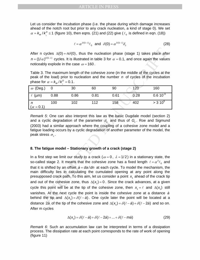
1/(1 )(1/ )n λα −= cycles. It is illustrated in table 3 for 0.1α = , and once again the values noticeably explode in the case 160ω = . Table 3. The maximum length of the cohesive zone (in the middle of the cycles at the peak of the load) prior to nucleation and the number n of cycles of the incubation phase for / 0.1
c
DMk kα = = .
ω (Deg.) 0 30 60 90 120 160
l (µm) 0.88 0.86 0.81 0.61 0.28 0.6 10-3
n ( 0.1α = )
100 102 112 158 402 > 3 105
Remark 5: One can also interpret this law as the basic Dugdale model (section 2) and a cyclic degradation of the parameter cδ and thus of cG . Roe and Sigmund (2003) had a similar approach where the coupling of a cohesive zone model and a fatigue loading occurs by a cyclic degradation of another parameter of the model, the peak stress cσ . 8. The fatigue model – Stationary growth of a crack (stage 2) In a first step we limit our study to a crack ( 0ω = , 1/ 2λ = ) in a stationary state, the so-called stage 2. It means that the cohesive zone has a fixed length 2
0α=l l and that it is shifted by an offset /a da dn=& at each cycle. To model the mechanism, the main difficulty lies in calculating the cumulated opening at any point along the presupposed crack path. To this aim, let us consider a point 1x ahead of the crack tip and out of the cohesive zone, thus 1( ) 0xΔ = . Since the crack advances, at a given cycle this point will be at the tip of the cohesive zone, then 1x = l and 1( )xΔ still vanishes. At the next cycle the point is inside the cohesive zone at a distance a& behind the tip and 1( ) ( )x aδΔ = − &l . One cycle later the point will be located at a distance 2a& of the tip of the cohesive zone and 1( ) ( ) ( 2 )x a aδ δΔ = − + −& &l l and so on. After m cycles 1( ) ( ) ( 2 ) ... ( )x a a maδ δ δΔ = − + − + + −& & &l l l (29) Remark 6: Such an accumulation law can be interpreted in terms of a dissipation process. The dissipation rate at each point corresponds to the rate of work of opening (figure 11)

MANUSCRIP
T
ACCEPTED
ARTICLE IN PRESS
11 1
( )( ) ( ) c cc
xd x x Gδδ σδ
= = (30)
It can be considered in a way as a perfect plastic law, the residual deformation being neglected in the computation according to the assumption of small displacements (remember that the maximum opening is .δ =c 4 7µm for PMMA).
Figure 11. The dissipation at each step (grey zone).
If a& is small compared to the cohesive zone length (this will be a posteriori checked, next to figures 12 and 13) then
[ ]1
11 1( ) ( ) ( 2 ) ... ( ) ( )d
xx a a a ma z z
a aδ δ δ δΔ = − + − + + − ∫
l& & & &l l l
& & (31)
In a stationary state, the crack grows at each step thus the fatigue criterion
(0) cδΔ = is reached at each step at the end O of the cohesive zone. Then using eqn. (26) (and the change of variables /s z= l )
2 4 21 10
0 0 0
1 1(0) ( )d ( )d (0) since ( )d3 3
c ccz z s s s s
a a aσ σ α
δ δ δ δ δΔ = = = =∫ ∫ ∫l l l% % %
& & & (32)
A Paris power law derives from this equation using the definition of α (the SIF and GSIF and their critical values coincide)
4 4 2
0 (0) with 3
cM IMDc Ic c
k Ka D D Dk K
σ δδ
⎛ ⎞ ⎛ ⎞= = =⎜ ⎟ ⎜ ⎟
⎝ ⎠ ⎝ ⎠
%l& (33)
It differs from the Paris law deduced in Jaubert, Marigo (2006) by the exponent (3 in Jaubert and Marigo 2006). The fatigue law is obtained in this paper as a limit law when the opening at each step becomes infinitely small. This difference is hardly surprising since their result is closely related to the geometry of the studied problem, the tearing of a thin film; in particular it is a simplified 1D problem. On the contrary, the above exponent coincides with that found in Abdelmoula et al. (2009 a and b) who used the Jaubert and Marigo approach. They consider successively 2D out of plane and in plane elastic problems: a mode III and a mode I cracks. But, in any

MANUSCRIP
T
ACCEPTED
ARTICLE IN PRESS
case, this exponent appears low when compared to data from Suresh (1998) on PMMA (figure 12). A joint use of a fatigue law and a cohesive zone model of Dugdale can be found in Okawa et al. (2006). But in this case the Dugdale zone is used to take into account in a simplified way the plastic effects of crack closure and crack blunting. The Paris propagation law is postulated independently.
1.0E-03
1.0E-02
1.0E-01
1.0E+00
1.0E+01
1.0E+02
0.1 1 10
a (µm)
K I
.
Figure 12. Crack advance per cycle a& vs. the SIF IK in PMMA, according to eqn. (33) (solid line), following data from Suresh (1998) (dashed line). Note that using data of section 4 = 1.12IcK MPa.m1/2 for PMMA. The smallness assumption of a& with respect to l is not rigorously verified numerically in figure 12 for all values of / 1IM IcK Kα = ≤ . It is observed that &a drops below /10l for α < 0.5 ( / 34l for α = 0.3 for instance) and it equals / 3l for α = 1. Thus the approximation used in eqn. (31) probably restricts the validity of the derived fatigue law to α < 0.5 . 9. The fatigue model – A modified cumulating law The Paris law found in section 8 (figure 12) is not totally in agreement with the experimental results found in Suresh (1998). The curves diverge from each other as α decreases, making the exponent 4 unlikely for small α . To change the Paris law exponent i.e. the slope in figure 12, it is necessary to modify the cumulated opening law. A law which involves the square of the opening instead of the opening itself gives less importance to small loads and would be closer to the experimental results. It must be emphasize that this does not interfere with the Dugdale cohesive law which remains unchanged. Moreover, as before, the same law can be used both for fatigue and monotonic loading. For a crack ( 0ω = ), under the assumption that the advance per cycle a′& is small compared to l , the modified cumulating law can be written
MANUSCRIP
T
ACCEPTED
ARTICLE IN PRESS
2 2 21( ) ( ) ( 2 ) ... ( )x a a maδ δ δ′ ′ ′ ′Δ = − + − + + −& & &l l l (34)
1
2 2 2 21
1 1( ) ( ) ( 2 ) ... ( ) ( )dx
x a a a ma z za a
δ δ δ δ′ ′ ′ ′ ′⎡ ⎤Δ = − + − + + −⎣ ⎦′ ′ ∫l
& & & &l l l& &
(35)
Remark 7: It is still possible to associate a dissipation rate to this accumulation law (remark 6) as a part of the opening work 1( ) cxδ σ (see eqn. (30) and figure 11)
2
1 11 1
( ) ( )( ) ( )c cc c
x xd x G xδ δ δ σδ δ
⎛ ⎞′ = =⎜ ⎟
⎝ ⎠ (36)
However, it is probably better now to consider this law as purely phenomenological. The fatigue criterion 2(0) cδ′Δ = is reached at each step at the end O of the cohesive zone. Then using eqn. (26) (and the change of variables /s z= l )
2 3 2 6 3 2
1 02 2 2
0 0
(0)1(0) ( )d ( )d 0.188 c ccz z s s
a a aσ σ α δ
δ δ δ′Δ = = =′ ′ ′∫ ∫
l%l l
%& & &
(37)
Since
1 2
0( )d 0.188s sδ =∫ % , and then the following Paris law can be derived
6 2 3 2
02
(0) with 0.188 c
c
IMDIc
Ka D DK
σ δδ
⎛ ⎞′ ′ ′= =⎜ ⎟
⎝ ⎠
%l& (38)
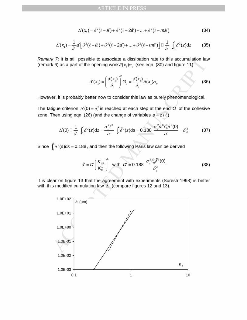
It is clear on figure 13 that the agreement with experiments (Suresh 1998) is better with this modified cumulating law ′Δ (compare figures 12 and 13).
1.0E-03
1.0E-02
1.0E-01
1.0E+00
1.0E+01
1.0E+02
0.1 1 10
a (µm)
K I
.
MANUSCRIP
T
ACCEPTED
ARTICLE IN PRESS
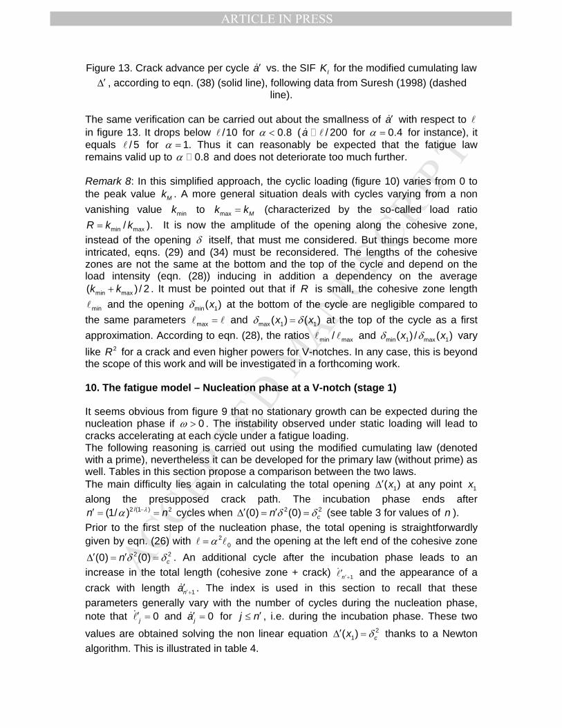
Figure 13. Crack advance per cycle a′& vs. the SIF IK for the modified cumulating law ′Δ , according to eqn. (38) (solid line), following data from Suresh (1998) (dashed
line). The same verification can be carried out about the smallness of a′& with respect to l in figure 13. It drops below /10l for α < 0.8 ( / 200& la for α = 0.4 for instance), it equals / 5l for α = 1. Thus it can reasonably be expected that the fatigue law remains valid up to α 0.8 and does not deteriorate too much further. Remark 8: In this simplified approach, the cyclic loading (figure 10) varies from 0 to the peak value Mk . A more general situation deals with cycles varying from a non vanishing value mink to max Mk k= (characterized by the so-called load ratio
min max/R k k= ). It is now the amplitude of the opening along the cohesive zone, instead of the opening δ itself, that must me considered. But things become more intricated, eqns. (29) and (34) must be reconsidered. The lengths of the cohesive zones are not the same at the bottom and the top of the cycle and depend on the load intensity (eqn. (28)) inducing in addition a dependency on the average
min max( ) / 2k k+ . It must be pointed out that if R is small, the cohesive zone length
minl and the opening min 1( )xδ at the bottom of the cycle are negligible compared to the same parameters max =l l and max 1 1( ) ( )x xδ δ= at the top of the cycle as a first approximation. According to eqn. (28), the ratios min max/l l and min 1 max 1( ) / ( )x xδ δ vary like 2R for a crack and even higher powers for V-notches. In any case, this is beyond the scope of this work and will be investigated in a forthcoming work. 10. The fatigue model – Nucleation phase at a V-notch (stage 1) It seems obvious from figure 9 that no stationary growth can be expected during the nucleation phase if 0ω > . The instability observed under static loading will lead to cracks accelerating at each cycle under a fatigue loading. The following reasoning is carried out using the modified cumulating law (denoted with a prime), nevertheless it can be developed for the primary law (without prime) as well. Tables in this section propose a comparison between the two laws. The main difficulty lies again in calculating the total opening 1( )x′Δ at any point 1x along the presupposed crack path. The incubation phase ends after
2 /(1 ) 2(1/ )n nλα −′ = = cycles when 2 2(0) (0) cn δ δ′ ′Δ = = (see table 3 for values of n ). Prior to the first step of the nucleation phase, the total opening is straightforwardly given by eqn. (26) with 2
0α=l l and the opening at the left end of the cohesive zone 2 2(0) (0) cn δ δ′ ′Δ = = . An additional cycle after the incubation phase leads to an
increase in the total length (cohesive zone + crack) 1n ′+′&l and the appearance of a crack with length 1na ′+′& . The index is used in this section to recall that these parameters generally vary with the number of cycles during the nucleation phase, note that 0j′ =&l and 0ja′ =& for j n′≤ , i.e. during the incubation phase. These two
values are obtained solving the non linear equation 21( ) cx δ′Δ = thanks to a Newton
algorithm. This is illustrated in table 4.
MANUSCRIP
T
ACCEPTED
ARTICLE IN PRESS
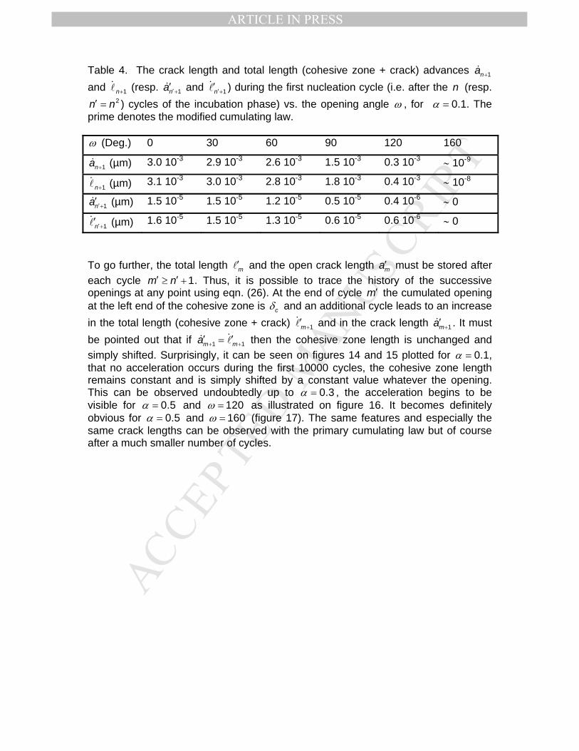
Table 4. The crack length and total length (cohesive zone + crack) advances 1na +&
and 1n+&l (resp. 1na ′+′& and 1n′+′&l ) during the first nucleation cycle (i.e. after the n (resp.
2n n′ = ) cycles of the incubation phase) vs. the opening angle ω , for 0.1α = . The prime denotes the modified cumulating law. ω (Deg.) 0 30 60 90 120 160
1na +& (µm) 3.0 10-3 2.9 10-3 2.6 10-3 1.5 10-3 0.3 10-3 ∼ 10-9
1n+&l (µm) 3.1 10-3 3.0 10-3 2.8 10-3 1.8 10-3 0.4 10-3 ∼ 10-8
1na ′+′& (µm) 1.5 10-5 1.5 10-5 1.2 10-5 0.5 10-5 0.4 10-6 ∼ 0
1n′+′&l (µm) 1.6 10-5 1.5 10-5 1.3 10-5 0.6 10-5 0.6 10-6 ∼ 0
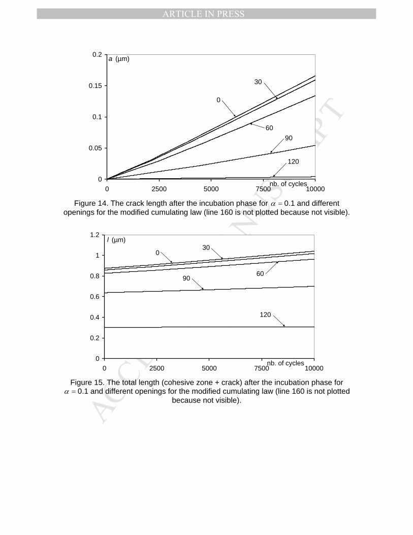
To go further, the total length m′l and the open crack length ma′ must be stored after each cycle 1m n′ ′≥ + . Thus, it is possible to trace the history of the successive openings at any point using eqn. (26). At the end of cycle m′ the cumulated opening at the left end of the cohesive zone is cδ and an additional cycle leads to an increase in the total length (cohesive zone + crack) 1m+′&l and in the crack length 1ma +′& . It must be pointed out that if 1 1m ma + +′ ′= && l then the cohesive zone length is unchanged and simply shifted. Surprisingly, it can be seen on figures 14 and 15 plotted for 0.1α = , that no acceleration occurs during the first 10000 cycles, the cohesive zone length remains constant and is simply shifted by a constant value whatever the opening. This can be observed undoubtedly up to 0.3α = , the acceleration begins to be visible for 0.5α = and 120ω = as illustrated on figure 16. It becomes definitely obvious for 0.5α = and 160ω = (figure 17). The same features and especially the same crack lengths can be observed with the primary cumulating law but of course after a much smaller number of cycles.
MANUSCRIP
T
ACCEPTED
ARTICLE IN PRESS
0
0.05
0.1
0.15
0.2
0 2500 5000 7500 10000
a (µm)
nb. of cycles
0
30
6090
120
Figure 14. The crack length after the incubation phase for 0.1α = and different
openings for the modified cumulating law (line 160 is not plotted because not visible).
0
0.2
0.4
0.6
0.8
1
1.2
0 2500 5000 7500 10000
l (µm)
nb. of cycles
030
9060
120
Figure 15. The total length (cohesive zone + crack) after the incubation phase for
0.1α = and different openings for the modified cumulating law (line 160 is not plotted because not visible).

MANUSCRIP
T
ACCEPTED
ARTICLE IN PRESS
0
25
50
75
100
0 60 120 180nb. of cycles
a and l (µm)
0 60 90 120
0 60 90 120
Figure 16. The total length (cohesive zone + crack, dotted line) and the crack length
(solid line) after the incubation phase for 0.5α = and different openings for the modified cumulating law (lines 0 and 30 almost merge and line 160 is plotted
separately).
0
20
40
60
80
0 1000 2000
a and l (µm)
nb. of cycles
Figure 17. The total length (cohesive zone + crack, dotted line) and the crack length (solid line) after the incubation phase for 0.5α = and 160ω = for the modified
cumulating law.
According to these remarks, for small values of α , one can assume that the nucleation phase is a stationary state, i.e. the crack advances per cycle a& and a′& are constant. Then formulas (28), (31) and (35) can be used to provide an analytical definition of the corresponding Paris fatigue law

MANUSCRIP
T
ACCEPTED
ARTICLE IN PRESS
20
2 3 20
2
(0) 2 with D and 3 1
(0) 3 with 0.188 and 1
c
c
q
cmDc c
q
mDc
ka D qk
ka D D qk
σ δδ λ
σ δδ λ
′
⎧ ⎛ ⎞⎪ = = =⎜ ⎟ −⎪ ⎝ ⎠⎨
⎛ ⎞⎪′ ′ ′ ′= = =⎜ ⎟⎪ −⎝ ⎠⎩
%l&
%l&
(39)
In eqn. (39) the dependence of a& and a′& on the opening ω occurs through the terms
0l and (0)δ% (table 1) and of course through the singularity exponent λ . The results are shown in table 5, the calculated values of a& and a′& can be compared to those extracted at the first nucleation cycle by the numerical procedure used to compute the crack advance in the general case (table 4). Table 5. The Paris exponents q and q′ , the constants D and D′and the crack advances per cycle a& and a′& for 0.1α = under the assumption of a stationary state. ω (Deg.) 0 30 60 90 120 160 q 4 4 4.1 4.4 5.2 11
D (µm) 29.5 29.4 30.3 31.9 37.4 69.9
a& (µm) 2.95 10-3 2.94 10-3 2.41 10-3 1.27 10-3 0.23 10-3 ∼ 0
q′ 6 6 6.1 6.6 7.8 16.6
D′ (µm) 16.7 16.6 17.0 17.9 21.1 38.3
a′& (µm) 1.7 10-5 1.7 10-5 1.4 10-5 4.5 10-6 3.3 10-7 ∼ 0
11. Conclusion Within the framework of quasi-brittle materials and thanks to a Dugdale cohesive zone model, the aim of Jaubert, Marigo (2006) to apply a single failure law being valid for both monotonic and fatigue loads with no additional dissipation process seems feasible. The failure law takes into account the cumulated opening during the cycles in the cohesive zone and the failure criterion is based on a critical value of this cumulated opening. Nevertheless, to be consistent with the experiments, the power β involved in the cumulating law must be adjusted. With the previous reasoning already encountered in sections 8-9, one may write for a crack ( 0ω = ) 1( ) ( ) ( 2 ) ... ( )x a a maβ β βδ δ δ′′ ′′ ′′ ′′Δ = − + − + + −& & &l l l (40) then
2( 1) 1
1 0
0
(0) with ( )d and c
c
ImDIc
Ka D B s s D BK
β β β ββ
β
σ δδ
δ
+ +⎛ ⎞′′ ′′ ′′= = =⎜ ⎟
⎝ ⎠∫
%l%& (41)

MANUSCRIP
T
ACCEPTED
ARTICLE IN PRESS
Thus, if a Paris exponent p can be identified from experiments on a crack growing under a fatigue loading (stage 2), the best fit gives / 2 1pβ = − . As a consequence, for small fatigue loadings ( / 0.3D
m ck kα = ≤ , i.e. loadings smaller than 30% of the failure load) a fatigue law for cracks nucleating at the root of a V-notch ( 0ω ≥ ) can be written
2(1 )
p
ImDIc
Ka DK
λ−⎛ ⎞′′ ′′= ⎜ ⎟
⎝ ⎠& (42)
where λ is the singular exponent of the elastic solution in the vicinity of the notch root. In the early growth stage (stage 1), the material seems to behave in an increasingly brittle way as the opening increases. For higher loadings such a stationary law is no longer valid. In particular, for large openings the initial crack growth is very slow, but it speeds up cycle after cycle as shown in figures 16 and 17. Acknowledgments This work is part of the research program OXYGENE supported by the French funding agency ANR (contract number ANR-08-PANH-12-05). References Abdelmoula R., Marigo J.J., Weller T. (2009a). Construction d’une loi de fatigue à
partir d’un modèle de forces cohésives : cas d’une fissure en mode III. C.R. Mécanique, 337, 53-59.
Abdelmoula R., Marigo J.J., Weller T. (2009b). Construction des lois de fatigue à partir de modèles de forces cohésives : cas d’une fissure en mode I. C.R. Mécanique, 337, 166-172.
Alfano G. (2006). On the influence of the shape of the interface law on the application of cohesive-zone models. Composites Science and Technology, 66(6): 723-730.
Alfano G., Crisfield M.A. (2001). Finite element interface models for the delamination analysis of laminated composites: mechanical and computational issues, Int. J. Num. meth. Engng., 50, 1701-1736.
Allix O., Ladeveze P. (1992) Interlaminar interface modelling for the prediction of delamination, Comp. Struct., 22, 235-242.
Atzori B., Lazzarin P., Meneghetti G. (2003). Fracture mechanics and notch sensitivity, Fatigure Fract. Engng. Mater. Struct., 26, 257-267.
Atzori B., Meneghetti G., Susmel L. (2002). Estimation of the fatigue strength of light alloy welds by an equivalent notch stress analysis, Int. J. Fatigue, 24, 591-599.
Barenblatt G.I. (1962). The mathematical theory of equilibrium cracks in brittle fracture, Advances in Appl. Mech., 7, 55-129.
Bazant Z.P., Planas J. (1998). Fracture and size effect in concrete and other quasibrittle materials, CRC Press, Boca Raton.
Boukharouba T., Tamine T., Niu L., Chehimi C., Pluvinage G. (1995) The use of notch stress intensity factor as a fatigue crack initiation parameter, Engng. Fracture Mech., 52, 503-512.

MANUSCRIP
T
ACCEPTED
ARTICLE IN PRESS
Bouvard J.L., Chaboche J.L., Feyel F., Gallerneau F. (2009) A cohesive zone model for fatigue and creep-fatigue crack rowth in single crystal superalloys. Int. J. Fatigue, 31, 868-879.
Dugdale D.S. (1960). Yielding of steel sheets containing slits, J. Mech. Phys. Solids, 8, 100-104.
Henninger C., Leguillon D., Martin E. (2007). Crack initiation at a v-notch – Comparison between a brittle fracture criterion and the Dugdale cohesive model, C.R. Mécanique, 335(7), 388-393.
Jaubert A., Marigo J.J. (2006). Justification of Paris-type fatigue law from cohesive forces model via a variational approach. Continuum Mech. Thermodyn., 18, 23-45.
Lawn B. (1993). Fracture of brittle solids – Second edition, Cambridge University Press.
Lazzarin P., Lassen T., Livieri P. (2003). A notch stress intensity approach applied to fatigue life predictions of welded joints with different local toe geometry, Fatigue Fract. Engng. Mater. Struct., 26, 49-58.
Lazzarin P., Zambardi R. (2001). A finite-volume-energy based approach to predict the static and fatigue behavior of components with sharp V-shaped notches, Int. J. Fracture, 112, 275-298.
Leguillon D. (1993). Asymptotic and numerical analysis of a crack branching in non-isotropic materials. Eur. J. Mech. – A/Solids, 12(1), 1993, 33-51.
Leguillon D. (2002). Strength or toughness ? A criterion for crack onset at a notch. Eur. J. Mech. – A/Solids, 21, 61-72.
Leguillon D., Murer S., Recho N., Li J. (2009) Crack initiation at a v-notch under complex loadings – Statistical scattering, International Conference on Fracture, ICF12, Ottawa, Canada, 12-17 July 2009.
Leguillon D., Sanchez-Palencia E. (1987). Computation of singular solutions in elliptic problems and elasticity, J. Wiley, New-York.
Leguillon D., Yosibash Z. (2003). Crack onset at a v-notch. Influence of the notch tip radius, Int. J. Fracture, 122, 1-21.
Livieri P., Lazzarin P. (2005). Fatigue strength of steel and aluminium welded joints based on generalized stress intensity factors and local strain energy values, Int. J. Fracture, 133, 247-276.
Madi Y., Recho N., Matheron P. (2004). Low-cycle fatigue of welded joints: coupled initiation propagation model, Nuclear Engineering and Design, 228, 179-194.
Maiti S., Geubelle P.H. (2005). A cohesive model for fatigue of polymers. Engng. Fract. Mech., 72, 691-708.
Mc Clintock F.A. (1958). Ductile fracture instability in shear, J. Appl. Mech., 25, 582-588.
Mi Y., Crisfield M.A., Davies G.A.O., Hellweg H.B. (1998). Progressive delamination using interface elements, J. Comp. mater., 32, 1246-1272.
Needleman A. (1990). An analysis of tensile decohesion along an interface, J. Mech. Phys. Solids, 38, 289-324.
Nguyen O., Repetto E.A., Ortiz M., Radovitzky R.A. (2001). A cohesive model of fatigue crack growth. Int. J. Fracture, 110, 351-369.
Novozhilov V. (1969). On a necessary and sufficient criterion for brittle strength, J. Appl. Math. Mech., (translation of P.M.M.), 33, 212-222.
Okawa T., Sumi Y., Mohri M. (2006). Simulation-based fatigue crack management of ship structural details applied to longitudinal and transverse connections, Marine Structures, 19, 217-240.

MANUSCRIP
T
ACCEPTED
ARTICLE IN PRESS
Planas J., Elices M. (1992). Asymptotic analysis of a cohesive crack : 1. Theoretical background, Int. J. Fract., 55, 153-177.
Planas J., Elices M. (1993). Asymptotic analysis of a cohesive crack : 2. Influence of the softening curve, Int. J. Fract., 64, 221-237.
Roe K.L., Siegmund T. (2003). An irreversible cohesive zone model for interface fatigue crack growth simulation, Engng. Fract. Mech., 70, 209-232.
Rose, L.R.F. (1987). Crack reinforcement by distributed springs, J. of the Mech. and Phys. of Solids 34, 383-405.
Seweryn A. (1994). Brittle fracture criterion for structures with sharp notches, Engng. Fract. Mech., 47, 673-681.
Seweryn A., Lukaszewicz A. (2002). Verification of brittle fracture criteria for elements with v-shaped notches, Engng. Fract. Mech., 69, 1487-1510.
Seweryn A., Mroz Z. (1998). On the criterion of damage evolution for variable multiaxial stress states, Int. J. Solids Structures, 35(14), 1589-1616.
Sih G.C. (1973). Some basic problems in fracture mechanics and new concepts. Engng. Fract. Mech., 5, 365, 377.
Suresh S. (1998). Fatigue of materials, second edition, Cambridge University Press. Tada H., Paris P.C., Irwin G. (2000). The stress analysis of cracks handbook, third
edition. ASME Press, New York. Taylor D. (1999), Geometrical effects in fatigue: a unifying theoretical model, Int. J.
Fatigue, 21, 413-420. Taylor D. (2008). The theory of critical distances, Engng. Fract. Mech., 75(7), 1696-
1705. Tvergaard V., Hutchinson J.W. (1992). The relation between crack growth resistance
and fracture process parameters in elastic-plastic solids, J. Mech. Phys. Solids, 40, 1377-1397.
Ural A., Krishnan V.R., Papoulia K.D. (2009). A cohesive zone model for fatigue crack growth allowing for crack retardation. Int. J. Solids Structures, 46, 2453-2462.
Xu X. and Needleman A. (1994). Numerical simulations of fast crack growth in brittle solids, J. Mech. Phys. Solids, 42, 1397-1434.
Yang B., Mall S., Ravi-Shandar K. (2001). A cohesive zone model for fatigue crack growth in quasibrittle materials. Int. J. Solids Structures, 38, 3927-3944.
Yosibash Z., Bussiba A., Gilad I. (2004) Failure criteria for brittle elastic materials, Int. J. Fracture, 125, 307-333.
Related Documents


