STATIC AND DYNAMIC HANDLING STABILITY OF SERVER RACK COMPUTERS Budy D. Notohardjono IBM Corporation Poughkeepsie, NY, USA Robert Sanders IBM Corporation Cary, NC, USA ABSTRACT This paper discusses the static and dynamic stability analysis of rack or frame computer/server products during shipping and relocation. The static stability is the ability of server products to resist tipping over on a typical raised floor in a datacenter or when it is installed in its operational product environment. The dynamic stability is the ability to resist tipping over when a velocity change occurs during re-location either on flat or inclined planes. The product consists of a frame or a rack in which components such as processor units, input- output units and power supplies are installed. The static stability analysis presented here calculates the tip over threshold angle, which is the maximum angle of an inclined plane on which the product can be placed without tipping over. The location of the installed components in a frame, the dimension and weight of the installed components, and the dimension of the product dictate the overall static stability of the product. Specifically, those parameters affect the location of the center of gravity of the product and the tip over threshold angle. The tip over threshold angle is a critical parameter influencing the dynamic stability of the product.. The dynamic stability of an unpackaged product moving on casters can be calculated using the conservation of mechanical energy principle. Finite element modeling is a good way to evaluate the dynamic stability of a product during manual handling or mechanical handling; for instance, on a forklift. The objective of the finite element modeling is to provide guidelines on the maximum speed, minimum radius curvature, and safe turning speed of a forklift when transporting a product. The main objective of the analysis presented here is to provide a method for analyzing the static and dynamic stability of a rack style computer server product during shipping, relocation, and handling. INTRODUCTION Rack mounted computer server products and other rack style products with a mass of 7 kg (15.4 lbs) or more must meet a minimum 10 degrees tilt test per UL 60950-1 section 4.1 (1). This is a static stability requirement for the installed product. Our focus herein will be on much more massive products weighing in excess of a ton. The final installation location of the server in a data center generally will not have any incline and stability further ensured with the use of leveling feet or other firm attachments. During relocation from the manufacturer’s location to the final destination, there will be surfaces such as the dock plate connecting a loading dock to a truck bed or other ramps which can be inclined at an angle up to 10 degrees. There are no dynamic stability tests or regulatory requirements for IT products during relocation. Two types of rack products will be discussed here, the first one is the nominal 19” frame (based on the width of rack mountable components) with actual total outside dimensions (width) of 24.5” (0.48 m). The second common one is the nominal 24” frame with the actual total outside dimensions (width) equal to 29.5” (0.75m). Racks used in this study can be populated up with up to a total of 42 units (U) of EIA (Electronic Industries Alliance) drawers or components. Racks up to 50U vertical capacity are now being produced in the IT industry. For 19” and 24” frames the width of the drawers or components installed are 19” and 24” respectively. One EIA unit (U) is 1.75” (44.45 mm) high. The total height of both racks from the floor is about 2.0 m. The total depth of the racks varies from 1.0 m to 1.4 m. The nominal frame size does not relate to the caster spacing nor its outermost frame dimensions. The rack or frame of the product is a welded steel structure. The total weight of the server frame depends on the configuration of the server. The nominal 19” frame structure without any assemblies or components installed weighed 275 kg (606 lbs.). The nominal 24” frame without components weighed 357 kg (787 lbs.) There are many different types of rack mountable assemblies such as processor units, input/output units and power units. The height of the assemblies varied from 8.8cm to 44cm while the depth varied from 0.8 m to 1 m. The weight of the assemblies varies from 41kg (90 lbs.) to 173kg (382 lbs.). A populated product weighs up to 1734 kg (3820 lbs.). For the nominal 19” frames, direction of rolling is controlled by placing two fixed (non-rotating) casters on the rear side. For the nominal 24” frames, four rotating casters are Proceedings of the ASME 2014 12th Biennial Conference on Engineering Systems Design and Analysis ESDA2014 June 25-27, 2014, Copenhagen, Denmark ESDA2014-20473 1 Copyright © 2014 by ASME Downloaded From: http://proceedings.asmedigitalcollection.asme.org/ on 09/19/2016 Terms of Use: http://www.asme.org/about-asme/terms-of-use

Welcome message from author
This document is posted to help you gain knowledge. Please leave a comment to let me know what you think about it! Share it to your friends and learn new things together.
Transcript

STATIC AND DYNAMIC HANDLING STABILITY OF SERVER RACK COMPUTERS
Budy D. NotohardjonoIBM Corporation
Poughkeepsie, NY, USA
Robert SandersIBM CorporationCary, NC, USA
ABSTRACTThis paper discusses the static and dynamic stability
analysis of rack or frame computer/server products duringshipping and relocation. The static stability is the ability ofserver products to resist tipping over on a typical raised floor ina datacenter or when it is installed in its operational productenvironment. The dynamic stability is the ability to resisttipping over when a velocity change occurs during re-locationeither on flat or inclined planes. The product consists of a frameor a rack in which components such as processor units, input-output units and power supplies are installed.
The static stability analysis presented here calculates the tipover threshold angle, which is the maximum angle of aninclined plane on which the product can be placed withouttipping over. The location of the installed components in aframe, the dimension and weight of the installed components,and the dimension of the product dictate the overall staticstability of the product. Specifically, those parameters affectthe location of the center of gravity of the product and the tipover threshold angle. The tip over threshold angle is a criticalparameter influencing the dynamic stability of the product..
The dynamic stability of an unpackaged product moving oncasters can be calculated using the conservation of mechanicalenergy principle. Finite element modeling is a good way toevaluate the dynamic stability of a product during manualhandling or mechanical handling; for instance, on a forklift.The objective of the finite element modeling is to provideguidelines on the maximum speed, minimum radius curvature,and safe turning speed of a forklift when transporting a product.
The main objective of the analysis presented here is toprovide a method for analyzing the static and dynamic stabilityof a rack style computer server product during shipping,relocation, and handling.
INTRODUCTIONRack mounted computer server products and other rack
style products with a mass of 7 kg (15.4 lbs) or more must meeta minimum 10 degrees tilt test per UL 60950-1 section 4.1 (1).
This is a static stability requirement for the installed product.Our focus herein will be on much more massive productsweighing in excess of a ton. The final installation location ofthe server in a data center generally will not have any inclineand stability further ensured with the use of leveling feet orother firm attachments. During relocation from themanufacturer’s location to the final destination, there will besurfaces such as the dock plate connecting a loading dock to atruck bed or other ramps which can be inclined at an angle up to10 degrees. There are no dynamic stability tests or regulatoryrequirements for IT products during relocation.
Two types of rack products will be discussed here, the firstone is the nominal 19” frame (based on the width of rackmountable components) with actual total outside dimensions(width) of 24.5” (0.48 m). The second common one is thenominal 24” frame with the actual total outside dimensions(width) equal to 29.5” (0.75m). Racks used in this study can bepopulated up with up to a total of 42 units (U) of EIA(Electronic Industries Alliance) drawers or components. Racksup to 50U vertical capacity are now being produced in the ITindustry. For 19” and 24” frames the width of the drawers orcomponents installed are 19” and 24” respectively. One EIAunit (U) is 1.75” (44.45 mm) high. The total height of bothracks from the floor is about 2.0 m. The total depth of the racksvaries from 1.0 m to 1.4 m. The nominal frame size does notrelate to the caster spacing nor its outermost frame dimensions.
The rack or frame of the product is a welded steel structure.The total weight of the server frame depends on theconfiguration of the server. The nominal 19” frame structurewithout any assemblies or components installed weighed 275 kg(606 lbs.). The nominal 24” frame without componentsweighed 357 kg (787 lbs.) There are many different types ofrack mountable assemblies such as processor units, input/outputunits and power units. The height of the assemblies varied from8.8cm to 44cm while the depth varied from 0.8 m to 1 m. Theweight of the assemblies varies from 41kg (90 lbs.) to 173kg(382 lbs.). A populated product weighs up to 1734 kg (3820lbs.).
For the nominal 19” frames, direction of rolling iscontrolled by placing two fixed (non-rotating) casters on therear side. For the nominal 24” frames, four rotating casters are
Proceedings of the ASME 2014 12th Biennial Conference on Engineering Systems Design and Analysis ESDA2014
June 25-27, 2014, Copenhagen, Denmark
ESDA2014-20473
1 Copyright © 2014 by ASME
Downloaded From: http://proceedings.asmedigitalcollection.asme.org/ on 09/19/2016 Terms of Use: http://www.asme.org/about-asme/terms-of-use
used. For the 24” frame this is done to ease locating theextremely heavy product within the final data center location.
STATIC STABILITY
The tip over threshold angle of a product is an indication ofthe static stability of a product. The static stability angle can beobtained by conducting a tilt test using tilt test equipment orother means of tilting the product. Alternatively, the tip overthreshold angle can be calculated based on the location of thecenter of gravity. Computer aided design software can calculatethe location of the center of gravity (CG) as shown in figure 1.Given the height of the center of gravity from the floor is hc andthe distance between casters is d, the static stability or the tipover threshold angle can be calculated using a simple geometricrelationship.
15.0tanch
d
Where
d = 18 “ (0.46 m) for 19” frame and 24.5 (0.61m) for 24”hC = the center of gravity is dependant upon weight
distribution in the rack
The wider the frame and the larger the distance from casterto caster the higher the static stability of the product will be.For example, for a 19” frame with 10 degrees tip over thresholdangle ( ) , the height of the center of gravity ch is 51 inches.It should be noted that a nominal 19” frame is a rack that canaccommodate a 19” drawer or component. By increasing thedistance between the caster by 1” or moving each caster 0.5”out, the tip over threshold angle will increase by 1 degree. Theproduct designer can try to lower the height of the center ofgravity of the product by placing heavy components at thebottom of the rack and populate the rack from bottom up.
In some cases it is desirable to calculate the effect ofcomponents with known center of gravity (CG1) as shown infigures 2 and 3 on the total tip over threshold angle. The offsetlocation or the horizontal coordinate and the vertical coordinateof the new CG as a result of the installation of a component areshown in equations 2 and 3 . The new tip over threshold anglecan be calculated using equation 4.
Horizontal coordinate of new CG:
Mm
xmx
xMmxm
l
lc
cll
)((2)
Vertical coordinate of new CG:
l
llc
clll
mM
hmMhh
hmMhmMh
0
0 )((3)
New tip over threshold angle:
)4(atan
tan
21
21
c
c
c
c
h
xd
h
xd
Where
angletilt:casterstwothebetweendistance:
frameloadedtheofcentergravitytheofcoordinate-x:frameloadedtheofcentergravitytheofcoordinate-y:frameemptytheofcentergravitytheofcoordinate-y:
loadtheofcentergravitytheofcoordinate-y:loadtheofcentergravitytheofcoordinate-x:
loadofmass:frameemptyofmass:
0
d
x
h
h
h
x
m
M
c
c
l
l
l
Figure 1 . Center of gravity (CG) and the tip over thresholdangle (α) [2]
Equation 2 can be used to calculate how much ballast needsto be added in order to increase the static stability. For example,if a 19” frame weighs 2000 lbs (8900 N) with 10 degrees tipover threshold angle, the height of the center of gravity will be51 inches. In order to bring the tip over threshold angle to 11degrees, 203 lbs of ballast needs to be added at the bottom ofthe frame.
2 Copyright © 2014 by ASME
Downloaded From: http://proceedings.asmedigitalcollection.asme.org/ on 09/19/2016 Terms of Use: http://www.asme.org/about-asme/terms-of-use

Figure 2. Calculating the tip over threshold angle as a functionof center of gravity [2]
Figure 3. Calculating the tip over threshold angle as a functionof center of gravity. [2]
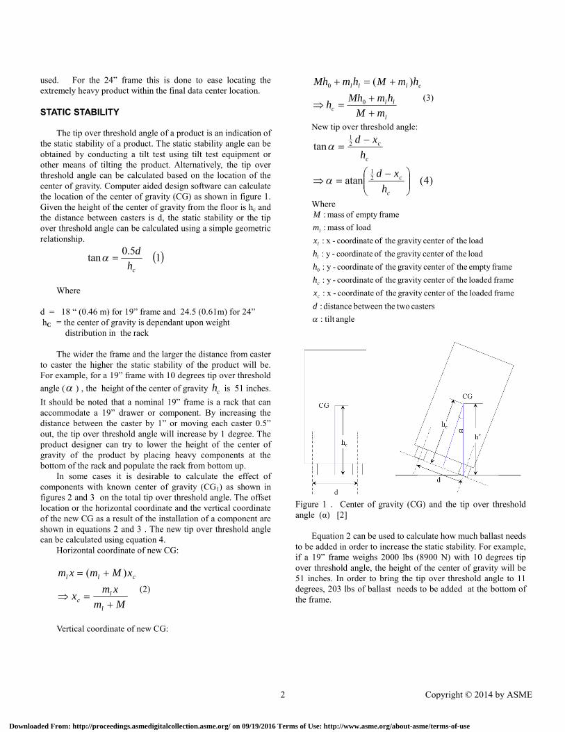
DYNAMIC STABILITYTo assess the dynamic stability, the critical velocity, which
is the maximum velocity change of product prior to tipover, willbe used as the appropriate index parameter. For manualproduct handling such as pushing a server frame on its owncasters, normally the moving direction is the direction front andback as shown in figure 4. For manual product handling the
front to back direction normally is dynamically more stablethan side to side direction due to higher caster to caster distancein the direction front to back. The moving direction can be on ahorizontal surface with the ramp angle (β as shown in figure 5 equal to zero), or on an inclined plane. Side to side stabilitycan be a factor during manual handling if the rack rotates suchthat only one caster stops if it hits an obstruction causing adynamic rotation of the entire rack. The other scenario isduring mechanical handling in which the rack may be placed onthe handling device in either of the two possible orientations.The critical velocity can be calculated based on conservationenergy principles. Neglecting the effect of friction between thecasters and the floor, the potential energy shown on the lefthand side of equation 5 is equal to the kinetic energy. Thecritical velocity change, or in short critical velocity *v , can becalculated using equation 6. Schematically, the change in thecenter of gravity height is shown in Figure 5.
62
521
*
2
hgv
mvhmg
Where
costan21
8sin2
7
1
*
1*
chdh
dh
hhh
h*: critical height of the center of gravity when the frametilt degrees
h1 : height of central gravity at ramp angle hc: height of the center of gravity centerd: distance between the two casters of the frame = 18” for
19” frame and 24.5” for 24” frame : tip over threshold angle
: ramp anglev*: critical velocity at which the frame will tip over when
it comes to a sudden stop
Based on equation 6, the critical velocity for 19” and 24”frames at different ramp angles and different tip over thresholdangles are shown in figures 6 and 7 respectively. Equations 6and 8 suggest that the dynamic stability of a product willincrease proportionally to the square root of the increase in thetip over threshold angle. By increasing the tip over thresholdangle from 10 to 12 degrees, the critical velocity increases by11%.
M1
mi
3 Copyright © 2014 by ASME
Downloaded From: http://proceedings.asmedigitalcollection.asme.org/ on 09/19/2016 Terms of Use: http://www.asme.org/about-asme/terms-of-use

For a frame with 10 degrees tip over threshold angle andzero ramp angle, the critical velocity is 0.63 m/s (2.07 feet persecond). At 12 degrees tip over threshold angle, the criticalvelocity is 0.69m/s (2.26 feet per second). By bringing the staticstability from 10 degrees to 12 degrees, the additional criticalvelocity is increased by 10%. Comparing 19” to 24” racks (with5.5” wider caster to caster distance), at 10 degrees tip overthreshold angle the critical velocity of a 24” frame is 0.74m/s(2.43 feet per second). The 24” frame has 17% higher criticalvelocity.
To verify the calculation above, a 24” frame was subjectedto an inclined impact test to simulate sudden velocity changeand the results are shown in Figure 8. The upper dashedexperimental line at 14 degrees tip over threshold angle has a40” high CG. The lower dashed experimental line at 12.5degrees tip over threshold angle has a 45” high CG. The actualtest showed lower critical velocity than the frictionlesscalculation as shown above. The reasons for discrepancies arethe friction between the caster and the platform and flexing ofthe frame and/or casters. For 24” frame, four rotating casters areused. During the experiment, the rotation of casters candecrease the distance between the centers of the casters (d).Also, when the rack tips up to one side the rack will deform andh* will not be as high as simulation calculates it.
Figure 4. Manual handling of a typical rack
Figure 5. Product at an incline angle [2]
4 Copyright © 2014 by ASME
Downloaded From: http://proceedings.asmedigitalcollection.asme.org/ on 09/19/2016 Terms of Use: http://www.asme.org/about-asme/terms-of-use
Fram e 19"
0
0.1
0.2
0.3
0.4
0.5
0.6
0.7
0.8
0.9
0 1 2 3 4 5 6 7 8 9
R am p ang le (degree)
Crit
ical
Velo
city
(m/s
)
tilt angle = 18°
tilt angle = 16 °
tilt angle = 8 °
tilt angle = 10 °
tilt angle = 14 °
tilt angle = 12 °
Figure 6. Critical velocity of a 19” frame [2]
Figure 7. Critical velocity of a 24” frame [2]
5 Copyright © 2014 by ASME
Downloaded From: http://proceedings.asmedigitalcollection.asme.org/ on 09/19/2016 Terms of Use: http://www.asme.org/about-asme/terms-of-use

Figure 8 Analysis vs. experimental data [2]
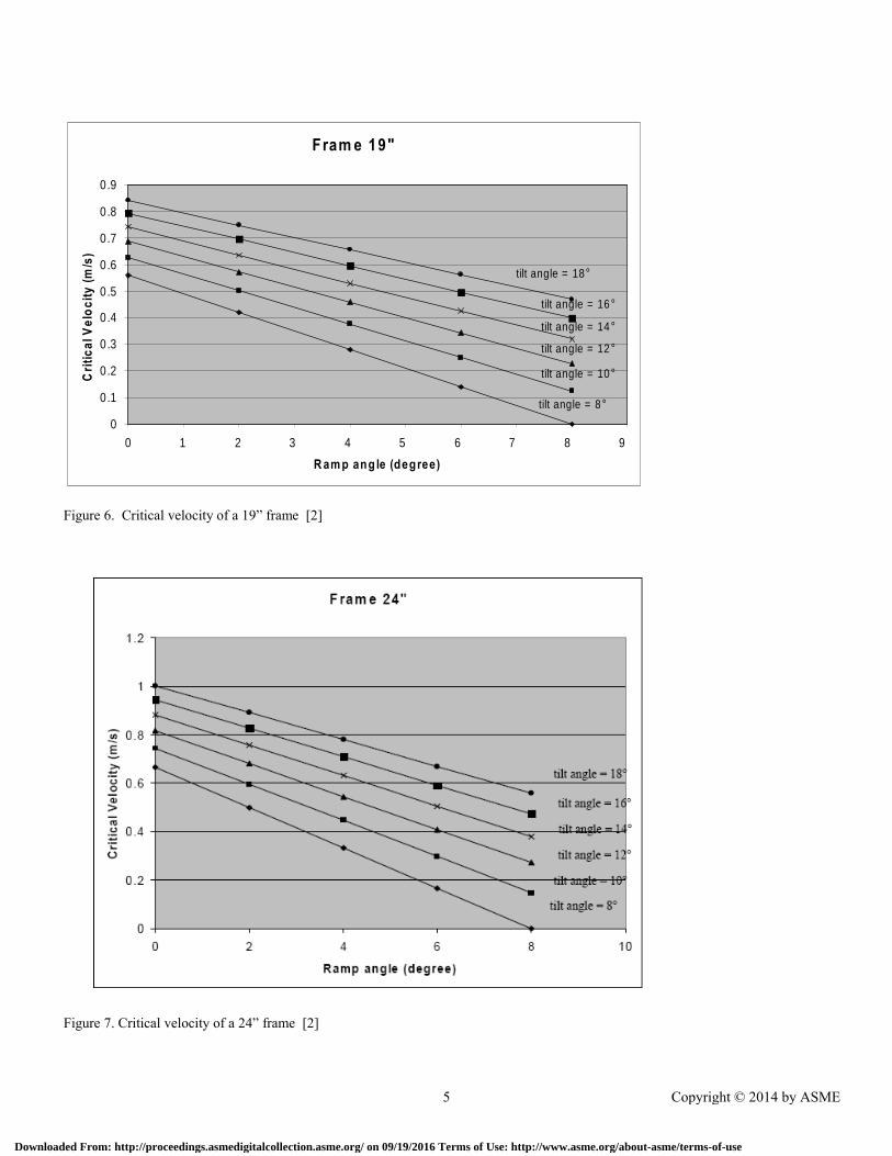
FINITE ELEMENT ANALYSIS MODELING OF RACKBEHAVIOR ON A FORKLIFT
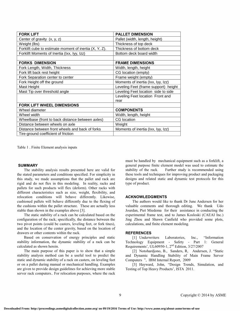
An ANSYS general purpose finite element analysis (FEA)model of a forklift, pallet and the main frame server product isshown in Figure 9. To conduct the simulation, the forklift ispresented by variable parameters as shown in Figure 10 and theframe on its pallet inputs for the simulation is shown in Figure11. All inputs for generating models are tabulated in Table 1.The parametric inputs are designed such that any size ordimension of a forklift, pallet and frame can be generated.
The simulation is done by applying a deceleration to theentire structure namely the forklift, the pallet and the frame.When the forklift is moving at constant speed then suddenlystops, the frame and the pallet would experience a velocitychange due to the sudden stop. In addition to the inputparameters for developing the FEA model, there are otherinputs needed,
• Forklift initial speed• Time it takes the forklift front wheels to come to a
complete stop from the speed specified.• Stop both wheels or just 1 front wheel• Curve radius for turning analysis• Coefficient of friction between the forklift tires and the
floor (it is assumed to be 0.3)• Coefficient of friction between the fork and the pallet
(coefficient between wood and steel is between 0.3 – 0.5)
• The analysis can be done if forks enter from longdimension or short dimension of pallet.
Rack tip over conditions can occur when a sudden stop ofthe forklift induces a high velocity change causing the frame totip over. It should be noted the forklift mast is often tilted backduring forklift movement. The effect of the forklift mast tiltingback on the critical velocities can be seen in Figures 6 and 7 for19” and 24” frame respectively. The forklift mast is assumed tobe 5 degrees tilted back (towards driver) As long as the bottomdeck of the pallet can hold the product and the forklift isdynamically stable, product tip over can be prevented. Thesimulation analysis can also calculate the load imparted by theforks to the bottom pallet deck. For a wooden pallet, when theforks transmitted 2500 lbs load to the bottom deck, the stress atthe bottom deck will reach the breaking (as shown in figure 12)strength of the wooden deck (1500 psi). Verification testingusing an Instron tensile machine shows that the bottom deckbroke at 2000 lbs. Due to wide variability of wood strengthinformation, we used the value of 2000 lbs as a limit when tipover will occur.
Another type of rack tip over can occur when the palletslides off of the forks. In this case, breaking of the bottomdeck, is not required for tip over to occur. A low coefficient offriction between the fork and the pallet can induce thiscondition.
Theoretically, the worst type of incident is the conditionwhere both the forklift and the frame tip over together. The
6 Copyright © 2014 by ASME
Downloaded From: http://proceedings.asmedigitalcollection.asme.org/ on 09/19/2016 Terms of Use: http://www.asme.org/about-asme/terms-of-use
program can analyze this scenario but we did not perform thisanalysis.
Figure 9 FEA model and Forklift, pallet and the product
Figure 10. Finite Element Model representing a forklift, thenumbers shown are inputs representing geometry of forklift
Figure 11. Finite Element Model representing a pallet and the product
7 Copyright © 2014 by ASME
Downloaded From: http://proceedings.asmedigitalcollection.asme.org/ on 09/19/2016 Terms of Use: http://www.asme.org/about-asme/terms-of-use

Figure 12. Transmitted Load to the Pallet
Figure 13. Critical velocity for different forklift speed [2]
8 Copyright © 2014 by ASME
Downloaded From: http://proceedings.asmedigitalcollection.asme.org/ on 09/19/2016 Terms of Use: http://www.asme.org/about-asme/terms-of-use
FORK LIFT PALLET DIMENSIONCenter of gravity (x, y, z) Pallet (width, length, height)
Weight (lbs) Thickness of top deck
Forklift cube to estimate moment of inertia (X, Y, Z). Thickness of bottom deck
Forklift Moments of Inertia (Ixx, Iyy, Izz) Bottom deck board width
FORKS DIMENSION FRAME DIMENSIONSFork Length, Width, Thickness Width, length, height
Fork lift back rest height CG location (empty)
Fork Separation center to center Frame weight (empty)
Fork Height off the ground Moments of inertia (Ixx, Iyy, Izz)
Mast Height Leveling Feet (frame support) height
Mast Tip over threshold angle Leveling Feet location side to sideLeveling Feet location Front andrear
FORK LIFT WHEEL DIMENSIONSWheel diameter COMPONENTSWheel width Width, length, height
Wheelbase (front to back distance between axles) CG location
Distance between wheels on axle Weight
Distance between front wheels and back of forks Moments of inertia (Ixx, Iyy, Izz)Tire-ground coefficient of friction
Table 1 . Finite Element analysis inputs
SUMMARYThe stability analysis results presented here are valid for
the stated parameters and conditions specified. For simplicity inthis study, we made assumptions that the pallet and rack arerigid and do not flex in this modeling. In reality, racks andpallets for such products will flex (deform). Other racks withdifferent characteristics such as size, weight, flexibility, andrelocation conditions will behave differently. Likewise,cushioned pallets will behave differently due to the flexing ofthe cushions within the pallet structure. These are actually lessstable than shown in the examples above [3].
The static stability of a rack can be calculated based on theconfiguration of the rack; specifically, the distance between thetwo pivot points (could be casters, leveling feet, or fork tines),and the location of the center gravity, based on the location ofdrawers or other contents within the rack.
Based on conservation of energy principles and staticstability information, the dynamic stability of a rack can becalculated as shown herein.
The main purpose of this paper is to show that a simplestability analysis method can be a useful tool to predict thestatic and dynamic stability of a rack on casters, on leveling feetor on a pallet during manual or mechanical handling. Examplesare given to provide design guidelines for achieving more stableserver rack computers.. For relocation purposes, where the rack
must be handled by mechanical equipment such as a forklift, ageneral purpose finite element model was used to estimate thestability of the rack. Further study is recommended usingthese tools and techniques for improving product and packagingdesigns and related static and dynamic test protocols for thistype of product.
ACKNOWLEDGMENTSThe authors would like to thank Dr June Andersen for her
valuable comments and thorough editing. We thank UdoJourdan, Piet Miedema for their assistance in conducting theexperimental frame test, and to James Kosloski (CAEAI Inc.)Jing Zhou and Shawn Canfield who provided some plots,calculations, and finite element modeling.
REFERENCES[1] Underwriters Laboratories, Inc., “Information
Technology Equipment - Safety - Part 1: GeneralRequirements’, UL60950-1, 2nd Edition, 3/27/2007
[2] Notohardjono, B., Sanders, R, Andersen, J. “Staticand Dynamic Handling Stability of Main Frame ServerComputers ”, IBM Internal Report, 2009
[3] Hayward, John, “Design Trends, Simulation, andTesting of Top Heavy Products’, ISTA 2011.
9 Copyright © 2014 by ASME
Downloaded From: http://proceedings.asmedigitalcollection.asme.org/ on 09/19/2016 Terms of Use: http://www.asme.org/about-asme/terms-of-use
Related Documents