STATEMENT OF TECHNICAL REQUIREMENTS INTEGRATED BRIDGE SYSTEM (IBS) FOR PROJECT -17A EED-50-45 Sep 2013 ISSUING AUTHORITY DIRECTORATE OF ELECTRICAL ENGINEERING INTEGRATED HEADQUARTERS MOD (NAVY) NEW DELHI 110011 RECORD OF AMENDMENTS Sno. Amendment Authority Date Signature 1

Welcome message from author
This document is posted to help you gain knowledge. Please leave a comment to let me know what you think about it! Share it to your friends and learn new things together.
Transcript

STATEMENT OF TECHNICAL REQUIREMENTS
INTEGRATED BRIDGE SYSTEM (IBS)FOR
PROJECT 17A
EED5045
Sep 2013
ISSUING AUTHORITY
DIRECTORATE OF ELECTRICAL ENGINEERING
I N T E G R A T E D H E A D Q U A R T E R S
M O D ( N A V Y )
N E W D E L H I 1 1 0 0 1 1
RECORD OF AMENDMENTS
Sno. Amendment Authority Date Signature
1

Revision Note: Nil
Historical Record: Nil
INDEX SL NO CHAPTER PAGE NO
1. CHAPTER 1 INTRODUCTION 462. CHAPTER 2 DESIGN SPECIFICATION 9123. CHAPTER 3 SYSTEM CONFIGURATION 13154. CHAPTER 4 SYSTEM APPLICATION 16185. CHAPTER 5 SYSTEM INTEGRATION REQUIREMENT 19216. CHAPTER 6 HUMAN MACHINE INTERFACE 22247. CHAPTER 7 TECHNICAL REQUIREMENTS 2527
LIST OF APPENDICES
SL NO. APPENDIX PAGE NO1. APPENDIX A SUMMARY OF APPLICABLE STANDARDS
AND SPECIFICATIONS2829
2
2. APPENDIX BGENERAL STANDARDS AND SPECIFICATIONS– POWER SUPPLY
30
3. APPENDIX C GENERAL STANDARDS AND SPECIFICATIONS– RELIABILITY & MAINTAINABILITY
3132
4. APPENDIX D GENERAL STANDARDS AND SPECIFICATIONS– DESIGN REQUIREMENTS
3334
5. APPENDIX E GENERAL STANDARDS AND SPECIFICATIONS– QUALITY ASSURANCE & CONTROL
3537
6. APPENDIX F GENERAL STANDARDS AND SPECIFICATIONS– EMI/EMC CONSIDERATIONS 38
7. APPENDIX G GENERAL STANDARDS AND SPECIFICATIONS–SCOPE OF SYSTEM SUPPLY 3958
8. APPENDIX H GENERAL STANDARDS AND SPECIFICATIONS– INSTALLATION AND COMMISSIONING
5960
9. APPENDIX J GENERAL STANDARDS AND SPECIFICATIONS– PRODUCT SUPPORT 6163
10. APPENDIX K – REFERENCE TABLE FOR IP RATINGS 64
11. APPENDIX L – SCOPE OF DELIVERABLES 65
12. APPENDIX M – SYSTEM MAINTENANCE REQUIREMENTS 66
CHAPTERI INTRODUCTION
1.1 Scope . This EED document provides the functional and technical specifications required from the Integrated Bridge System (IBS) envisaged to be fitted onboard new construction projects of the IN. The IBS system has been conceived to include the navigation aids, equipment and sensors which are integrated in order to allow centralised access to sensor information and to enable effective Bridge Resources Management from workstations, with the aim of increasing the safety of the ship and her navigation efficiency. This document also brings out the details of the subsystems of IBS and other ship fitted systems and their interface requirement with IBS.
1.2 Applicable Documents . The documents to be referred for this SOTR are specified in Appendix ‘A’. While every effort has been made to ensure the completeness of the list, document users are cautioned that they must meet all specified requirements of the documents cited in this SOTR, whether or not they are listed. The design and technical requirements of IBS and its subsystem have been elucidated in subsequent Chapters. The aspects of Standards and Specifications, Quality
3

Assurance, Installation/ Training and Maintenance have been detailed at Appendices ‘B’, ‘C’, ‘D’, ‘E’, ‘F’, ‘G’, ‘H’, ‘J’ ‘K’ ‘L’ and ‘M’. These do not include documents cited in other sections of this SOTR or recommended for additional information or as examples.
1.3 Order of Precedence . Unless otherwise noted herein or in the contract, in the event of a conflict between the text of this document and the references cited herein, the text of this document takes precedence. Nothing in this document, however, supersedes applicable laws and regulations unless a specific exemption has been obtained.
1.4 Acronyms . The following acronyms are included herein for ready reference and are applicable for the purpose of this SOTR.
ACRONYMS(a) IBS Integrated Bridge System(b) ECDIS Electronic Chart Display Information System(c) ARPA Automatic Radar Plotting Aid(d) MFC Multi Function Console(e) MFD Multi Function Display(f) VDR Voyage Data Recorder(g) IPMS Integrated Platform Management System(h) BDCS Battle Damage Control System(j) IMO International Maritime Organisation(k) AIS Automatic Information System(l) AWOS Automatic Weather Observation System(m) WSDI Wind Speed and Direction Indicator(n) DGPS Digital Global Positioning System(p) CMS Combat Management System(q) COTS Commercial Of The Shelf(r) ADR Air Direction Room(s) RFP Request For Procurement (t) IEC International Electrotechnical Commission(u) ENC Electronic Navigation Charts(v) IHO International Hydrographic Organisation(w) RNC Raster Navigation Charts(x) AML Additional Military Layers(y) SIC Station in Control(z) GUI Graphic User Interface(aa) OEM Original Equipment Manufacturer(ab) CCTV Closed Circuit Television(ac) PIP Picture in picture(ad) TLG Tiled Layer Graphic(ae) ECP Emergency Conning Position(af) TFT Thin Film Transistor
4

(ag) LCD Liquid Cristal Display(ah) MCR Machinery Control Room(ai) VHF Very High Frequency(aj) OBD Optical Bearing Device(ak) ICC Integrated Captain’s Console(al) HMI Human Machine Interface(am)
UPS Un interrupted Power Supply
(an) BITE Builtin Test Equipment(ao) LRU Line Replaceable Unit(ap) SOTRs Statement of Technical Requirements(aq) SDN Ships Data Network(ar) ICD Interface Control Document(as) POU Portable Operating Unit(at) PDU Portable Diagnostic Unit(au) SHHD Ship House Hold Data(av) OBTS Onboard Training System(aw) PDR Preliminary Design Review(ax) CDR Critical Design Review(ay) EMI/EMC Electromagnetic Interference / Electromagnetic Compatibility(az) GBE Gigabit Ethernet(ba) OFC Optical Fibre Cable(bb) HATs Harbour Acceptance Trials(bc) SATs Sea Acceptance Trials(bd) FATs Factory Acceptance (be) MTTR Mean Time to Repair(bf) MTBF Mean time Between Failure(bg) DI/DR Defect Identification/Defect Rectification(bh) INCAT Indian Naval Catalog of Inventory
1.5 Definitions . The following definitions are included herein for ready reference and are applicable for the purpose of this SOTR.
DEFINITIONS
(a) Ships Data Network
This constitutes the digital backbone (wired/ optical) available in at least dual redundant topology onboard a warship intended to carry Ships House Holding Data and other VOIP/ data packets from multiple sources to the various receiving systems.
(b) Graceful Degradation
This is a concept wherein a system is designed in such a fashion that a single point failure of the entire system is contained. In case of failure of any module/ card, the system
5
DEFINITIONS
would remain operational albeit, with reduced performance/ efficiency
(c) Fault Tolerant Software
This includes software designed in a fashion that all errors and exceptions are handled appropriately avoiding hanging of software.
(d) Platform This is a term used occasionally to indicate a Ship(e) ‘Class of Ship’ This is a term used to indicate a group of Ships with the same
structural design. The Equipment fit may vary at times. (f) Latency This is the delay in the signal flow from source to sink in a
system. This is more perceptible in digital systems.(g) Bridge The Bridge is the primary hub of remote control of all the Ship’s
activities and is generally situated in the highest position of the superstructure at the fore of the ship.
(h) Ops Room This is the compartment located deep inside the ship where all the warfighting operations are carried out.
(j) Weather Deck
All areas onboard ships which are exposed to marine conditions are known as weather deck. These are also referred to as upper decks.
(k) Machinery Compartments
These are all the compartments generally at the lower half of the ships which contain all the propulsion, power generation and other machinery onboard a ship which are also very noisy.
(l) Convergence This means the combined use of the communication backbone and the data terminals onboard a ship for multiple services.
1.6 General Descriptions/ Requirements . The purpose of IBS is to enable centralised access to sensor information or command/control from various workstations thereby increasing the safety of the ship and her navigational safety. The system should be designed to collect, process and present navigational and other relevant data to improve the efficiency of the ship’s navigation and safety at sea. The system solution is to be based on wellestablished marine standards, COTS technology and local product/maintenance support. The system shall have high MTBF of 8000 hours and MTTR of Fifteen minutes for high reliability and operational availability. The consequences of any failure in the system will be minimized and the operability is kept as high as possible.
6

CHAPTER2 DESIGN SPECIFICATIONS
2.1 Design Requirements. The design of IBS should comply the specific requirements enumerated in the succeeding paragraphs.
(a)The Integrated Bridge System is envisaged to facilitate safe navigation of the ship and meeting all the specified requirements of IMO. The main features of the IBS are modular design and COTS based technology with specified customization. The impetus shall be on considerable reduction in interconnections and cabling while ensuring future growth.
(b) Integration with ship’s systems as specified having Gigabit Ethernet backbone.
(c) Management and monitoring of all subsystems, with a provision of isolating subsystems from the proposed system as and when required by the user/ controller.
(d)Simultaneous operation of all workstations and applications with no degradation of performance.
(e)Convergence capability in terms of video and data on single network meeting the varied requirements of multiple users spread across the platform. The bandwidth available for the convergence must ensure no delays on the account of latency / losses, thereby achieving the desired Quality of Service (QoS) of Speed, Accuracy, Clarity and Redundancy.
(f) Graceful degradation and efficient reconfigurability feature to have uninterrupted operation / performance.
(g)Extensive builtin features for DI / DR upto LRU level and provision for both on and offline diagnostics.
(h) Survivability . The system should have dynamic rerouting in case of damage with following features:
(i) Redundant architecture.
(ii) Redundancy management system to provide online and offline health monitoring of the system.(iii) Redundant connection between sub units and nodes.
(j) The IBS should be microprocessor (latest processor available at the time of bidding) based digital, distributed architecture with COTS technology.
(k) The IBS will be online independent dual redundant Fiber Optic Gigabit Ethernet network and interfaced with IPMS through gateway computer for complete monitoring of machinery status.
7

2.2 Communication Requirement . The IBS must be designed with a dual redundant or better Gigabit Ethernet (GBE) or higher capacity backbone, suitably ruggedized for fitment onboard IN ships. All the segments / subsystems of the IBS must communicate with each other through the backbone. The system must provide multiple services (voice / data / video as applicable) using defined Quality of Service. The desired throughput of the system must be at least 2 Gbps and must support a latency of less than 500 mili seconds. The system must incorporate the following:
(a) Architecture . The proposed architecture must provide for dual redundancy and also a graceful degradation of the system in the event of failure / loss of connection. The critical components of system must have 100% redundancy and must be controlled by Fault Tolerant Software so that in case of any unit level failure, the system performance will degrade gracefully rather than be rendered nonoperational in entirety. Accordingly, each of the subsystems must be designed keeping in view the requirements of redundancy and fault tolerance.
(b) Data Interface. The system shall be designed to meet the following requirements for data interface:
(i) Network interface for interfacing Ethernet based systems and ship's LAN / SDN catering to 10/100/1000 Mbps or Gigabit Ethernet with integrated function.(ii) RS232C and RS422 bidirectional Serial links for interfacing existing systems and to cater for any future additional systems.
(iii) Serial digital interfaces IAW ITUT standards and Euro COM Standards(iv) OFC interface.
2.3 Redundancies . The system availability can be further enhanced by having several redundancies at all levels of the system i.e. redundancy in the Consoles, data bus, LRUs (Processors, I/O boards, navigation sensor interface units, communication boards etc), and sensors. Further, as a minimum the system should cater for the following:
(a) All sensors shall be connected to two or more Sensor Concentrators mounted in separate Network Interface Cabinets (NICs). These NICs shall be located in different compartments / Fire Zones.
(b) Each Sensor Concentrator (set) shall receive signals from all relevant sensors and shall be fully redundant to the other sensor concentrator.
(c) A redundant Gigabit fibre optic Ethernet network shall distribute all information to/from the sensors and control units.
(d) Each multifunction console (MFC) shall be able to display any application (ECDIS, ARPA and Conning) and the bridge shall consequently be fully operable with one or even more MFCs out of order.
8

(e) Master – Master configuration (each MFW contains the same SW) i.e., clientserver architecture shall not be used.
2.4 System Architecture. The IBS design shall be based on Open architecture with dual redundant Fibre Optic Gigabit Ethernet system. The design architecture shall cater for Reliability, Interoperability, Modularity, Ease of Operation, Maintenance Aspects, and Modification in Parameters values. It is essential that the hardware and software shall be compliant to open architecture standards and shall be based on the following key principles:
(a) Seamless integration
(b) Uniform presentation of information
(c) Uniform principles of operation
(d) User simplicity to avoid human error
(e) Multi function workstations (MFW)
(f) Multi redundant system
(g) COTS equipment / ease of maintenance
(h) Master – Master configuration. It implies that every MFC shall be capable to exercise control of any of the Navigational radars and as ECDIS server. However, control will be exercised only on one of the MFC at a time through heirarchy of login password and other MFCs will provide monitoring features for that particular application.
2.5 Open System . The IBS shall be an ‘open system’ conferring consistency and dependability features based on the selection of standard nonproprietary hardware and software, and acknowledged international standards for Operating Systems, System bus, Interfaces, Protocols etc. 2.6 Growth Margin . The system design should cater for growth margin to enable upgradation, expansion and integration with an external system during the system life cycle.2.7 Reliability. The IBS shall have high reliability conferred by its high availability ratio obtained from the use of proven, rapidly maintainable technologies. The operational life of the equipment shall be clearly mentioned by the supplier. The OEM shall submit necessary documents/certificates as basis for calculation of notified MTBF.2.8 Power Supply. IBS is to be supplied with power supply from both the main and alternate source of electrical power with automated changeover switch capable to switch over from Normal to Alternate power supply and vice versa in less than 100 ms. The IBS shall operate on ship’s main power supply or suitable step down transformer 415/ 380 V to 230V 50 Hz 1 phase for input power supply to the system. Further, all other secondary supplies required for the system operation are to be derived from the main input power supply. In addition, IBS should be supplied with online UPS fitted with maintenance free lead acid sealed battery capable to provide backup power supply for at least 30 minutes. The batteries
9

should be sourced indigenously. The IBS shall comply to the power supply interruption and shut down conditions mentioned below:
(a) If subjected to an orderly shutdown, the IBS should, upon switchingon, come to an initial default state.
(b) After a power interruption, full functionality of the IBS should be available after recovery of all subsystems.
CHAPTER3 SYSTEM CONFIGURATION
3.1 IBS Sub Systems . The under mentioned sub systems shall form integral IBS configuration (final ‘Class of Ship’ wise configuration will be as per IN nomination/specification) and
10

are to be sourced from IHQ MoD(N) nominated make/vendors as applicable. The major subsystems are as follows:
(a) Gyros with specified repeaters(b) Echo Sounder(c) Electro Magnetic Log (d) DGPS(e) Navigation radars I Band and E/F Band(f) Optical Bearing Device
(g) A ‘Fixed type’ Voyage Data Recorder of latest version and maximum available channels.
(h) Integrated Captain’s Console.
(j) Automatic Identification System (AIS)
(k) Transmitting Magnetic Compass.
(l) Automatic Weather Observation System (AWOS) for Wind Speed, and Direction, Temperature, Pressure and Relative Humidity or WSDI (Wind Speed Direction Indicator).
3.2 Integration with Ship’s Systems. The IBS will be interfaced with the following ship’s systems:
(a) Steering System with Autopilot
(b) Ship’s Data Network (SDN)
(c) Integrated Platform Management System/BDCS with gateway computer.
(d) IBS should be able to provide the following outputs to the Combat Management System (CMS):
(i) Navigational Radar raw video.
(ii) Navigational Radar ARPA tracks.
(e) ECDIS (If available)
3.3 The IBS shall be one integrated, distributed architecture system covering all systems mentioned above and in specific cases where the ship systems do not provide data as required by IBS (viz syncro /proprietary protocols), the necessary conversion is to be undertaken at the IBS end.
3.4 In addition to the sub systems mentioned at para 3.1 above, the IBS configuration should include the following components:
11
(a) Multi Function ConsolesNumber of MFCs and location to be specified by Order Placing Authority.
(b) Multi Function DisplayNumber of MFDs and location to be specified by Order Placing Authority.
(c) Portable Operating Unit – Number to be specified by Order placing Authority
(d) Portable Diagnostic Unit Number to be specified by Order placing Authority
(e) Dual redundant Fiber Optic Gigabit Ethernet Network along with network switches and/or hubs and gateways, as required.
(f) Sensor Integration Units/ Sensor Concentrators to provide seamless interface with navigational aids and ship fitted systems. (g) Radar Switching units or similar equipment to enable control of the radar transreceivers and other sub systems through Multi Function Consoles.
3.5 Voyage Data Recorder. The vendor shall offer latest model of VDR (at the time of bids submission) and shall meet growth margin as specified for future. The number of recording channels and micro phones for VDR will be specified by Order placing authority. The VDR shall meet the following (but not limited to) requirements:
(a) The VDR should be able to record the voice communications in the bridge and the verbal instructions passed over the machinery, action and conning intercoms. The number of microphones provided inside the Bridge, in Bridge wings and in the MCR should ensure recording of all voice communication. Inaddition, VDR should be able to integrate with at least one VHF channel.
(b) The communication recorded should be reproducible in a ‘timeevent log’ format.
(c) The ‘protective capsule’ for the VDR, as required by IMO regulations, needs to be provided. Access to VDR data should be through password control.
(d) Provision should be made for longterm storage of information (up to 90 days) on VDR. Facility for external storage of the old records is also to be provided.
(e) It should be possible to replay selected recorded data on a commercial PC. The PC and associated replay software should be included in the scope of supply of the IBS.
(f) The VDR should conform to the contemporary Performance Standards promulgated by IMO and published in the contemporary edition of IEC.
12
3.6 Optical Bearing Device (OBD ) . The IBS vendor shall offer latest model of OBD (at the time of bids submission). The OBD should be capable of plotting visual position lines on the ECDIS, thereby providing a means of plotting a visual fix on the ECDIS directly. Additionally, it should be able to provide the target identity feedback to the operator from the AIS. Further, the OBDs should conform to IP 66 requirements. Exact number of the OBDs required would be included in the ship/ class specific RFP.
3.7 Integrated Captain’s Console. The IBS package will include the Integrated Captain’s Console(s) (ICCs) for the integrated bridge. The Console(s) is to be in the form of a chair with builtin internal communication suite (linked with the ship’s intercom system), a collapsible front desk, overhead reading lamp, collapsible/ foldable LCD touch screen providing IBS inputs built in the arm rest. The console should have a suitable footrest and the reclining features built in. Exact number of the ICCs would be included in the ship/ class specific RFP.3.8 Uninterruptible Power Supply. Each software intensive sub unit of IBS which require safe shut down shall be powered through a ruggedised UPS. The UPS shall supply this vital IBS equipment with continuous power during a loss of ships power for a minimum period of 30 minutes. The UPS shall prevent power transients as ship service power is lost and restored such that no loss of control or maloperation of the IBS units results from these transitions. Battery charge circuits within each unit shall be capable of recharging the battery from 40% capacity to 80% capacity within 8 hours. They shall be protected from undercharge and overcharge. Battery charging shall be automatic and shall not affect normal unit operation. The IBS supplier is to propose the capacity of the UPS units required. Batteries used onboard for UPS should be selected from standard size of batteries available in Indian market. The UPS should be type tested and shall meet the EMI/EMC requirements as per MIL STD 461 E requirements.3.9 Bridge Design. A twodimensional isometric layout design of the bridge will be required to be provided to IHQ MoD(N) for approval. The design should be in compliance with IMO and class rules.
13

CHAPTER4 SYSTEM APPLICATION
4.1 System Functionalities. The IBS system should provide for the following functionalities:
(a) ECDIS
(b) ARPA
(c) Conning Display
4.2 The IBS will be computing and displaying information required for Bridge Operation on the MFCs. The functions that will be computed and displayed on the MFCs are mentioned in the succeeding paragraphs.4.2.1 ECDIS Functionas.
(a) Each MFC should be able to display the complete ECDIS functions.
(b) The ECDIS functions provided should conform to the contemporary Performance Standards promulgated by International Maritime Organisation (IMO) and International Electrotechnical Commission (IEC).
(c) ENC Loading Capability. All MFCs should accept ENCs in all IMO approved formats. All MFCs should have the permissions for updating Electronic Navigation Charts (ENCs) for chart corrections. The chart correction undertaken on any one MFC should be automatically updated on other MFCs. In addition, it should meet following standards:
(b.i)S63 IHO Data Protection Scheme Edition 1.1.1 or an upgrade.
(b.ii) ECDIS display and presentation IHO S52 PresLib Edition 3.4.or upgrade.
(b.iii) RNC S 61 (Product Specifications for Raster Navigation Charts) or an upgrade.
(b.iv) The system should be able to load and display the Additional Military Layers (AMLs).
(d) Specific Requirements. The ECDIS should provide the following facilities inaddition to those specified by the contemporary IMO standards:
(c.i)Renaming and labelling of routes and waypoints.
14

(c.ii) Labelling of target tracks should be possible on ARPA. Labels of the targets labelled on ARPA should appear automatically on ECDIS.
(c.iii) Data of a tracked target is to be correlated, so as to show a single track on ECDIS display.
4.2.2 Radar Functions.
(a) The IBS should be interfaced with all the ‘I’ and E/F band navigation radar transreceivers, installed on the ship. It should be possible to control the radar(s) from MFCs in control.
(b) Each MFC should also provide for radar functions as mandated by IMO regulations. It should be possible to manipulate the radar controls namely range scale, pulse length, PRF, antisea clutter, antirain clutter, interference suppression etc from the MFC which is the ‘StationinControl’.
(c) The radar functionality on each MFC should conform to the contemporary Performance Standards promulgated by IMO and IEC document.
4.2.3 Conning Display Mode.
(a) One of the selectable modes/ menus of the MFC should include the ‘Conning Display’ mode. The purpose of the Conning Display Mode is to present the ship’s configuration/ status in graphical manner and data collected from the ship’s navigation, maneuvering, propulsion and steering sensors, in groups.
(b) The GUI of the Conning Display Pages should be customisable, depending upon the class of the ship on which the system is being fitted. The customisation is to be approved by IHQ MoD (N).
(c) The list of Conning Display Pages should include, but not be limited to the following pages:
(b.i) Met and Astro Page . This page should display information received from met sensors and shall include, but not be limited to such as Wind Speed and Direction, Temperature, Pressure and Relative Humidity. Inaddition, there should be software provided by OEM for carrying out astronomical and tidal predictions based on the date, time and position of the ship.
(b.ii) Navigational Data Page . This page should display information received from navigational sensors and shall include, but need not be limited to:
15

(aa) Date and Time.(ab) Ship’s position.(ac) Speed over ground.(ad) Heading.(ae) Course over ground.(af) Rudder angle.(ag) Depth.(ah) Drift.
(b.iii) Machinery Status Page . This page should display status of the following machinery (but not be limited to) received from IPMS/ACS:
(aa) Main Engines.
(ab) GTGs/DAs.
(ac) ACs.
(ad) Steering Gears.
(ae) Ref Plants.
(af) Fuel and Water State of the ship.
(ag) Graphical display of propulsion machinery and bow thrusters (if fitted) is also to be available.
(iv) CCTV Page. Cameras fitted as part of the IPMS system should be able to feed the IBS CCTV page on demand, through the gateway computer. Further, operator selectable mode is to be provided for cameras to sequentially display images in Picture in Picture (PIP) or Tiled Layer Graphics (TLG) form from all or a selected camera.
16

CHAPTER5 SYSTEM INTEGRATION REQUIREMENTS
5.1 Sensor Integrator and related functions . The IBS vendor shall provide integration of the sensors and other systems and the integration should consist:(a) Built in redundancy in all aspects from sensor input, sensor data display and navigational data output.
(b) All sensor data shall be distributed to all workstations.
(c) Should one process fails, other processes will work as before and only a part of the user functionality will be affected.
(d) A three tier layered concept as follows:
(i) Sensor data collector processes.
(ii) Sensor data databases (modular databases with no dependencies between different databases, no other databases shall be affected if one database fails)
(iii) HMI processes display data from the databases. HMIs and operator shall be password protected.
(e) Automatic selection of the best navigational data based on the available sensors. The operator may also choose to use the sensor manually.
(f) An integrated and synchronized alarm system shared amongst all network units. Alarms may be configured to block lower level alarms, to clarify the actual fault for the operator and to reduce the number of alarms.
(g) Synchronization of system clock on all network units using the UTC time from GPS or any other UTC time source.
(h) System resource usage by each process, such as CPU, memory (phys. and virtual) etc., are constantly monitored, in addition to available resources. Alarms are distributed to the operators if limits are exceeded.
(j) The LAN network traffic is constantly monitored and alarms distributed if exceeding configured limits. Highly configurable processes. i.e., the NMEA interpreter process that may be configured via a text file to interpret any of the standardized NMEA protocol messages and any future ones without a revision.
17

(k) Full VDR functionality, including picture grabbing of any running application. Storing of sound from several sound channels. Storing of a configurable set of database variables.
(a) VDR Replay functionality for dedicated workstations.
5.2 Seamless Integration. The IBS will consist of multifunctional workstations connected by a redundant Gigabit Ethernet network, each being able to function as any main navigational system selectable on a menu, i.e. ECDIS, ARPA, conning display and safety/alarm monitoring. All the navigation systems and sensors are to be integrated into the IBS network, allowing operation, and monitoring and alarm identification on any of the Multi Function Consoles (MFC). The track file data and raw radar video are required to be provided to the Ship’s Data Network (SDN) for onward transmission to other equipment onboard (e.g.CMS). The IPMS will also be seamlessly integrated with IBS to ensure complete monitoring of machinery status. The specific requirements will be detailed at the time of TNC. Only vendors with experience of integrating and installing similar systems onboard warships will be considered.
5.3 Software Back Up. The IBS Vendor will be required to provide Software Backup with each system, along with the necessary permissions to load on the MFCs. System software backup is to be provided with necessary software and drivers to read the backup images and reboot the system.
5.4 Network Monitoring Capability. The system should have provision to integrate with other open architecture based systems. System design is to cater for ‘Network Monitoring’. The dual redundant fibre optic network should be on mastermaster configuration and there should not be any time interval in change over in case of failure of one of the networks. Failure of the network should be notified to the operator through Audio/Visual alarm.
5.5 System Integration. The IBS vendor shall assume the role of System Integrator and shall interface with Navigation Systems. The IBS vendor shall liaise with IN for finalisation of protocols of all interfaced equipment.
5.6 The subsystems of IBS shall have spare serial and Ethernet standard interface ports with the requisite drivers embedded in the system, or provision for future enhancement due to system upgradation, augmentation in system capability or integration with any other systems as found necessary by the Indian Navy.
5.7 System Integration Support . The IBS supplier shall perform the following tasks to support this integration effort as part of the overall effort involved in the design, development, delivery, installation and commissioning of the IBS:
18
(a) IBS Architecture Review. The IBS supplier shall review the system architecture specified herein with respect to the latest trends in the industry and provide feedback to the IN regarding the same.
(b) Interface Control Document. The IBS supplier shall produce the Interface Control Document (ICD) and validate the same based on information obtained from the various equipment/machinery suppliers, the yard and the ship designers. The ICD shall be the governing document for all signal interfaces between the platform machinery and systems and the IBS. The ICD shall be kept under strict configuration control. After the ICD is frozen, it shall not be modified without permission from the IN. If necessary, the IBS supplier shall conduct Interface Control Meetings with the machinery vendors, yard, and IN staff present to ensure proper coordination and control of controls interface issues. WESEE will be the overall system Integrator and Interface Control Document approving authority.
(c) Computer Program Test Plans, Procedures and Reports. The IBS supplier shall develop computer program test plans, procedures and reports for all IBS software in accordance with latest IEC/ISO standards.
CHAPTER6 HUMAN MACHINE INTERFACE6.1 Human Machine Interfaces. The system should be conferred with an advanced, easy to use manmachine interface through rich graphic Mimics, and audio & visual alarm pages on the consoles. In general, the HMI features should provide information that is clearly understood using consistent style, requested manual inputs should be easily understood, with continuously displayed information and functional areas presented in consistent manner that are optimised and supplementary information should be readily available. There should be plausibility checks for unintended manual inputs and personnel should be able to execute basic functions
19

6.2 Multi Function Consoles (MFCs ) . The IBS will have Multi Function Consoles (MFCs) that will consist a ruggedized TFT (LCD) display, a keyboard with associated tracker ball and latest version processor (s). The Multi Functional Consoles (MFCs) are to be identical (except where specified herein) and interchangeable, both functionally and physically. The display should be of at least 23 inch (diagonal) size, with a minimum screen resolution of 1200 x 1600 pixels. There should be a provision on the MFCs to switch the displays to day or night mode, with a facility for dimming up to ‘zero’ level. The MFCs be loaded with latest antivirus. The colour scheme of MFCs and other sub units of IBS shall be Light Grey RAL 7001.
6.3 Locations of MFC. The MFCs would be installed in the Chart House, Bridge, Ops Room, Flag Bridge, ECP, MET office and ADR (if applicable). Exact number and locations of MFCs would vary depending on the type/ class of the ship. The same would be specified in the ship/ class specific RFP.
6.4 HMI Requirement. The IBS vendor will have to customize the HMI for all application as specified by the IN during various design reviews. The HMI and MFCs shall meet the following broad requirements:
(a) Introduction Page. A custom designed page displaying a welcome message on the backdrop of the digital silhouette of the ship, the Naval Ensign and the National Flag. This would be the first page displayed on each MFC when the system is powered on.
(b) MFCs should be configured using the MasterMaster (also referred to as MultiMaster) concept. Each MFC should have the ability to fulfill all IBS functions.
(c) Where control of sensor (like radar transreceivers) is being exercised by the earmarked MFC fitted inside the bridge and Ops Room, that MFC would become the ‘StationinControl’ for the relevant sensor/ function. In such a case, no other MFC should be able to exercise control of that sensor. However, the information from that sensor should continue to be available for display on all other MFCs. An indication that an MFC is the ‘StationinControl’ for a particular sensor should be available on the other MFCs.
(d) Means should also be available to relinquish control of a sensor from the MFC, when desired, so that another MFC may assume the ‘StationinControl’ for that sensor.
(e) There should be a provision on the MFCs to switch the displays to day or night mode, with a facility for dimming up to ‘zero’ level.(f) HMI should accept manual inputs. For manual inputs that may cause unintended results, the IBS should request confirmation before acceptance, thus providing a plausibility check.
20

6.5 The IBS consoles should have the facility for installation of voice communication equipment supplied by the Indian Navy. The following specifications are essential features of the MFCs:
(a) All MFCs shall run in fast application switching mode making it possible to switch between IPMS pages, Radar displays, ECDIS (conforming to performance standards promulgated by IMO and published in the latest edition of International Electro technical Commission document IEC 61774), Navigation Information Display (NIS) without limitations.
(b) All MFCs shall operate on the same Operating System version.(c) MFCs shall include sensor instrument selection logic permitting automatic and manual selection of sensors.(d) MFCs shall be designed with a synchronised functionality in relation to sensor selection, i.e. sensor data shall be presented in real time and same value on all MFCs on the network.(e) MFCs shall have a common alarm system for ECDIS, radar and conning display systems. This alarm system shall be configurable by the operator through standard HMI.(f) USB ports on all MFCs should be disabled and data should be retrievable through CD writer.
6.6 Multi Function Displays (MFDs). Inaddition to the MFCs, Multi Function Displays (MFDs) are to be provided with the system. MFDs are to be TFT colour displays of 1012 inch diagonal size. These are to serve as repeater indicators for navigational data and to display the information from Conning Display Pages. The MFDs should be loaded with latest antivirus.6.7 Location of MFDs. MFDs would be installed in Bridge, Chart House, Secondary Steering Position, Ops Room, ECP, Flag Bridge and Bridge Wings. Exact number and locations of MFDs would vary depending on the type/ class of the ship. The same would be specified in the ship/ class specific RFP.
6.8 MFD Day/Night Mode. There should be a provision on the MFDs to switch the displays to day or night mode, with a facility for dimming up to ‘zero’ level. Additionally, the data displayed should be readable during daytime (minimum 1000 Nits). MFDs fitted in exposed locations viz bridge wings, ECP, bridge top etc would need to be ruggedized to meet IP 66 standard.
6.9 Portable Operating Units (POUs). POU should be provided that is capable of being plugged into any of the remote terminal sockets of the data bus. The POUs should have all design and operation features of MFC and must be able to be used as Man Machine Interface, in times of emergency for operation as a console. The number of POU and Network terminal sockets required and their locations will be specified in the RFP.
21

6.10 Portable Diagnostic Unit (PDU). One in number PDU should be catered for undertaking the complete diagnostics of the IBS. The PDU should be able to be plugged into remote terminal socket on the IBS network for carrying out online and offline diagnostics. The number of Network terminal sockets required and their locations will be specified in the RFP.
22

CHAPTER7 TECHNICAL REQUIREMENTS 7.1 Technical Specification. The key technical requirements that are essential to be complied with are as follows:
(a) The system shall be based on microprocessor design and provide increased operational capability through use of digital control system technology in a distributed architecture. (b) The development environment shall be a realtime software development environment, which has been proven in use in the development of IBS for warships. A common environment and development tool shall be used for the undertaking dynamic analysis, development of simulation models, MMI graphics pages, and the core of the control system software.
(c) The design of the IBS should achieve the following: (i) Provide endtoend system response better than 500ms. (ii) Increase the system survivability through redundancy of critical components.(iii) Reduce system capital and installation costs using a modern data bus with redundancy and survivability features.(iv) Provide proven onboardembedded operator team training capability. Onboard training capability shall be available at all of the IBS consoles/screens. (v) Provide for a growth margin of 25% in the system capability without the addition of new consoles. This shall be in the form of spare card slots in the MFCs to add more input/output capacity and memory available in the EEPROMs to add more software functionalities. (vi) Provide for graceful degradation in the event of total failure of the control system. (vii) Provide MTTR of equal to or better than 15 minutes & critical function MTBF of not less than 8000 Hrs. (viii) Provide high tolerance to conducted & radiated EMI/EMC as per standards at AnnexureA.(ix) Provide interchange of cards to other similar units & perform the function at the new unit without any software changes.(x) Provide proven multifunction and fully redundant consoles, which can assume any and all of the monitoring and control functions such as ECDIS, ARPA, conning and limited control of IPMS.
7.2 System Implementation. The system installation and implementation should meet under mentioned requirements:
(a) The functionality of the IBS should ensure that its operation on one each MFC in the bridge, chart house and ops room is as effective as for the entire system put together.
23

(b) Gyro, Log, DGPS, AIS, Echo Sounder and Nav Radar(s) feed are to be hardwired (200 meters of cable length for each sensor) with one each MFC in the Bridge, Chart House/ Ops Room, in addition to the IBS distribution units. (c) Failure of a sensor/ feed from any sensor should not affect the functions of other sensors/ IBS. Status of such failed sensors is to be indicated as data not available on relevant pages with suitable alarm.
7.3 Alarm Management. The IBS shall provide each MFC with audible and visual indications of alarms and warnings, which along with resulting functional restrictions can be easily understood. Separate audible tones shall be used to indicate the various status alerts, alarm and warning conditions. Acknowledgement of the alarm or warning shall cause the audio alarm to be silenced. For the MFCs colocated in one compartment, eg the Enclosed Bridge, facility is to be provided for muting the audio alarm for all the MFCs from any one MFC. The audio visual alarm should be provided in priority and be in functional groups. The number of alarm types and their release should be kept as low as possible by providing indications for information of lower importance.
7.4 Data Logging. The IBS should be supplied with a laser colour A 3 printer and a black and white printer to provide on demand a hardcopy of all errors, alarms, warnings, and changes to engine orders should also be supplied with IBS systems. Each log is to include a time stamp and logs are to be printed in a chronological sequence. Further, it should be feasible to filter/shortlist the alarms equipment wise as decided by the operator. The printers are to be directly connected to the main IBS network via console processors, which shall be used as print servers. The B&W printer and the colour printer shall be installed in a rugged Printer Cabinet that shall be suitably shock mounted to meet the environmental requirements.
7.5 DATA ARCHIVING. The IBS is to include a minimum of one data logger to log online real time events and alarms for IBS and interfaced sensors/systems. The IBS data (measurements, commands, alarms, parameters) have to be stored in the hard disk. The capacity of the hard disk should to adequate to store the complete system data for a minimum of 30 days. The variables selected from the database will be recorded at every status change and are preserved for a number of days as defined by the StationinCommand. The default number of days will be 07 days. It should be possible to take a dump of the logged data from the hard disk onto magnetooptic discs, from the IBS console(s). The space on the hard disk for logging of data should be managed on a FIFO basis.
7.6 Applicable Standards . The environmental, shock and EMI/ EMC standards for the equipment supplied within the scope of IBS are to comply with IEC 60945 standards or contemporary amended versions of various IEC standards. Inaddition, the UPS supplied as part of IBS should meet Mil Std 461 EMI/EMC requirements. A list of applicable standards is placed at AnnexureA.
24

7.7 OnBoard Training System. The IBS is to include an onboard embedded operator team training capability. The OBTS shall allow any MFC, group of MFC, to be placed in training mode. When in training mode, MFC are to respond as if in normal operational mode, except that they are to interact with a simulator rather than with the ship’s navigation equipment. Consoles that are in training mode shall be precluded from displaying “real” navigation data and from issuing commands to real navigation equipment. When in training mode, MFCs are to remain active (though in the background) in the main data bus to ensure that at least one MFC is in control of the ship’s bridge operation. In the event of failure of the last unit in control, one or more of the units in training mode are to revert to control mode based on a predetermined sequence subject to validation and acceptance of the control by the operator. Data communications for training shall not use the networks used for normal operational communication. The OBTS will operate on a separate network and not on the control network that is processing real time sensor data. Onboard training shall include the provision of an instructor station with the capability to start and stop the training exercise (freeze, run), record and playback, and reset the simulation and consoles in training mode to a selected initial condition.
7.8 Builtin Test Equipment (BITE) . The BITE software should run automatically at powerup in any mode of operation and should have control over the subsystem hardware. The design of the system should cater for the following features:
(a) Builtin Test (BIT) facility is to identify, locate and indicate to the operator any fault that has occurred in the system during operation in all modes. BIT messages shall be displayed at the bottom of the operator colour screens on all MFCs.
(b) The BIT shall isolate all detected faults to Line Replaceable Unit (LRU) level. The BITE shall be capable of identifying the faults of physical communication breaks also.
(c) It shall be possible to initiate a BIT of any other IBS equipment from any HMI after the use of proper password or other means of authentication. (d) Online help display of IBS maintenance manual for preventive and corrective maintenance procedures and Circuit Schematics of the subsystems of IBS (and operators manual) shall be possible from any console.
Appendix A(Refers to Para 1.2)
SUMMARY OF STANDARDS / SPECIFICATIONS APPLICABLESl No Particulars Reference Remarks1. Internal Cabling NES 5262. Internal Wiring Defence Standard 6112 (Part 18)3. Cable Entry Gland DGS/EED/VI/1535/R6
specification
25
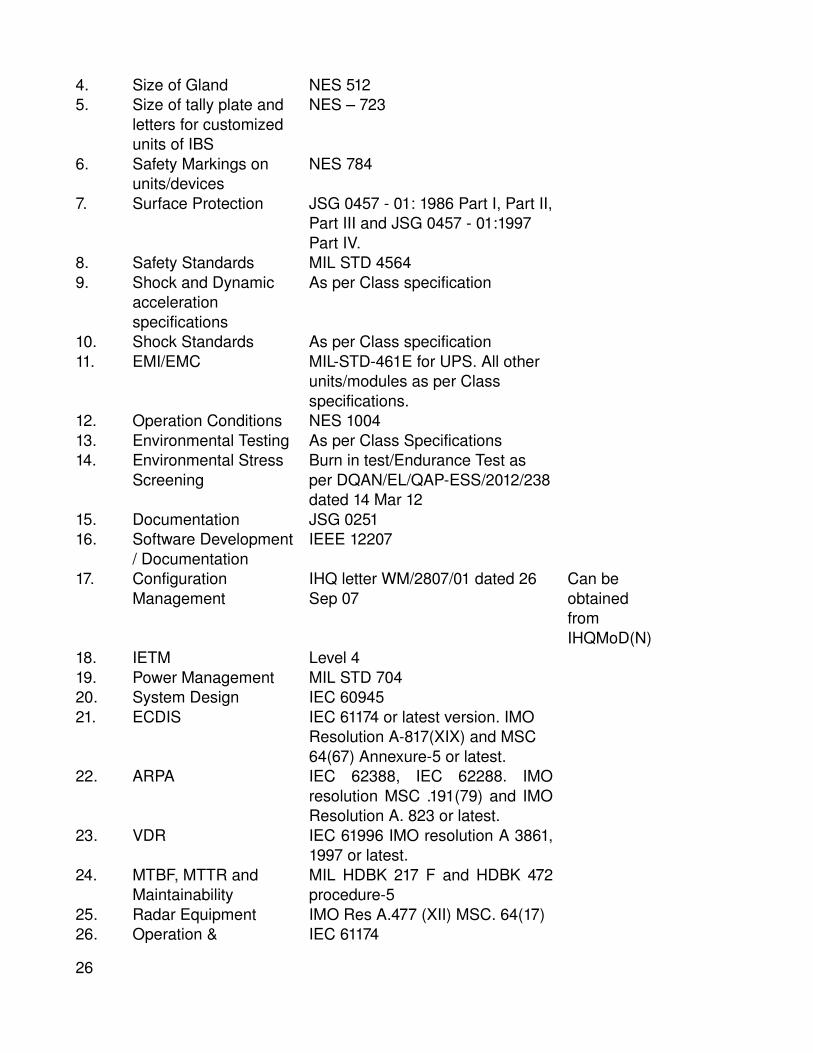
4. Size of Gland NES 5125. Size of tally plate and
letters for customized units of IBS
NES – 723
6. Safety Markings on units/devices
NES 784
7. Surface Protection JSG 0457 01: 1986 Part I, Part II, Part III and JSG 0457 01:1997 Part IV.
8. Safety Standards MIL STD 45649. Shock and Dynamic
acceleration specifications
As per Class specification
10. Shock Standards As per Class specification11. EMI/EMC MILSTD461E for UPS. All other
units/modules as per Class specifications.
12. Operation Conditions NES 100413. Environmental Testing As per Class Specifications14. Environmental Stress
ScreeningBurn in test/Endurance Test as per DQAN/EL/QAPESS/2012/238 dated 14 Mar 12
15. Documentation JSG 025116. Software Development
/ DocumentationIEEE 12207
17. Configuration Management
IHQ letter WM/2807/01 dated 26 Sep 07
Can be obtained from IHQMoD(N)
18. IETM Level 419. Power Management MIL STD 70420. System Design IEC 6094521. ECDIS IEC 61174 or latest version. IMO
Resolution A817(XIX) and MSC 64(67) Annexure5 or latest.
22. ARPA IEC 62388, IEC 62288. IMO resolution MSC .191(79) and IMO Resolution A. 823 or latest.
23. VDR IEC 61996 IMO resolution A 3861, 1997 or latest.
24. MTBF, MTTR and Maintainability
MIL HDBK 217 F and HDBK 472 procedure5
25. Radar Equipment IMO Res A.477 (XII) MSC. 64(17)26. Operation & IEC 61174
26

Performance27. Radar & ECDIS IEC 62288 Specification for colour
and symbology 28. Nav. Information IMO res. MSC 191(79) 2006
Performance standards for the presentation of Nav. Related information on ship borne Navigational Displays.
29. Speed & Distance Data
IMO Res A.824(19) – Performance standards for devices to indicate Speed and Distances.
30. Software Development ISO 12207 Software Development Process DODSTD2167A/498 Defence System Software Development
Appendix B(Refers to Para 1.2 )
GENERAL STANDARDS AND SPECIFICATIONS POWER SUPPLY
27

1. Power Supply. The equipment will be supplied with ship’s main power supply or 230 V, 50 Hz single/ three phases as primary supply (to be supplied by Order placing authority). The equipment should be able to withstand ± 10 % fluctuation in voltage and ± 3 % fluctuation in frequency. Provision for transient protection should exist.
2. All the supplies integral to the system shall be generated using transformers/converters and should be developed/delivered along with the system as Power Supply Panels of the system. All the software intensive sub systems should be supplied with online UPS with 30 minutes endurance.
3. IBS is to be supplied with power supply from both the main and alternate source of electrical power with automated changeover switch capable to switch over from normal to Alternate power supply and vice versa in less than 100 ms. The IBS shall operate on ship’s main power supply or suitable step down transformer 415/ 380 V to 230 V 50 Hz 1 phase for input power supply to the system. Further, all other secondary supplies required for the system operation are to be derived from the main input power supply. In addition, IBS should be supplied with online UPS fitted with maintenance free lead acid sealed battery capable to provide backup power supply for at least 30 minutes. The batteries should be sourced indigenously. “The IBS manufacturer should specify QOS of UPS and be amenable to provision of supply from a ship installed centralized UPS system meeting the QOS specified”.
Appendix C(Refers to Para 1.2 )
GENERAL STANDARDS AND SPECIFICATIONS RELIABILITY AND MAINTAINABILITY
1. System Performance .
(a) Design Review . The system developer is required to schedule formal design reviews during the development of the system to ensure that the user requirements and envisaged functionalities are captured correctly at the design stage. The frequency of the design reviews will be finalized during the contract conclusion
(b) Reliability . The system design should be based on standard engineering principles to provide a reliable product. The reliability figures in terms of MTBF / MTTR shall be estimated by the OEM
28

and submitted as part of the technical proposal. The system performance will degrade gracefully in the event of a failure. The system will contain no 'single point' control, whose malfunctioning would result in a catastrophic failure. The functional redundancy will be available in the shortest possible time through hardware/software reconfiguration without loss of data and time. The design will cater for adequate fail safe features.
(c) Maintainability . The system shall be able to run online and offline maintenance diagnostics centrally. The builtin test equipment (BITE) will be capable of detecting and localising faults down to a single replaceable PCB/Module within 5 minutes of the fault occurrence. The monitoring system will also be designed to indicate corrective action either by a display or through a fault detection code, with amplifying notes used in conjunction with the maintenance manual. The hardware maintenance system will be designed as an offline one and isolation of faulty units in the maintenance mode will be on a nottointerfere basis with the healthy system. The manufacturer will prepare and submit the following data on maintainability:
(i) Maintainability programme(ii) Maintainability prediction
2. MTBF/MTTR . System shall be designed for high MTBF of greater than 8000 hours and low MTTR of not exceeding 15 minutes.
3. Commonality . The manufacturer to mention the level of commonality achieved within the system at the following levels.
(a) Module/sub module level(b) PCB level(c) Component level.
4. Configuration Management . To keep track of the platform specific modifications undertaken on the systems and to ensure suitable documentation of the upgrades incorporated throughout the life cycle of the equipment, there is a requirement for maintaining configuration control. The policy guidelines for configuration management has been promulgated by IHQ vide letter WM/2807/01 dated 26 Sep 07. The supplier is to submit the Configuration Management (CM) document in accordance with these guidelines prior to issue of Inote.
29

Appendix D(Refers to Para 1.2 )
GENERAL STANDARDS AND SPECIFICATIONS DESIGN REQUIREMENTS
1. Safety Standards . The system should offer total safety to personnel from moving parts and other associated equipment from shock. Safety standards as per MIL STD 4564 should be met. All units are to be provided with earthling bolt. Where units are connected with the ship's main, fuse protection is to be provided. Each unit where dangerous voltages are present will bear a Red Label stating in bold white characters the highest voltages inside the unit. Doors and panels are to be provided with safety door switches, wherever necessary.
2. Dimension . Overall dimension and weight of the equipment shall be kept to the minimum as possible considering the limitation of space on ships.
3. Standardisation and Metrication . The equipment and all its components are to be fully in metric system. It is to be ensured that assemblies, subassemblies, components, parts and material used conform to the specified requirements and standards.
4. Mounting Arrangement . The mounting arrangement for the system on the ship need to be indicated after consultation with the respective authorities. The manufacturer needs to coordinate with the ship yard / installation agency for the installation details. The procedure for installation inspection if applicable needs to be indicated.5. Tally and Diagram Plates . All tallies and diagram plates shall be anodized aluminum alloy or naval brass. Size of tally plate and their letters shall conform to specification NES723. VOLTAGE DANGER tally shall be provided on the system at a permanent place where required. Safety markings on the units and associated devices/ units shall conform to NES 784.
6. Lifting Arrangement . Units weighing more than 40 kg shall be provided with collar eyebolts or suitable lifting lugs/ arrangements. If the eyebolts cannot remain in situ after the unit has been installed on the ship, provision is to be made for their securing arrangement on the unit.
30

7. Terminal . Bolted type terminal and crimped socket of electrolytic copper are to be provided for all incoming and outgoing cables. Adequate spare terminals are also to be provided.
8. AntiCondensation Heating . Wherever necessary, equipment shall be provided with anticondensation heating elements, which are to be switched on automatically when the equipment is switched off.
9. Cabinet Cooling . Adequate precautions need to be taken during the design of the cabinets to ensure sufficient cooling and circulation of air.
10. Shock Mounts . The equipment would be mounted on shock mounts onboard the ship. Suitable shock mounts are to be provided by the firm.
11. Environment protection Specification . The various modules/ sub modules of the system are distributed throughout the ship. While most of the equipment devices are fitted in internal sheltered locations, some like MFDs, OBDs, Antennae etc. are fitted on upper decks. These need to be designed with specified Ingress Protection (IP) ratings.
31

Appendix E(Refers to Para 1.2 )
GENERAL STANDARDS AND SPECIFICATIONS QUALITY ASSURANCE / CONTROL
1. Quality Assurance . The manufacturer should submit draft QAP (Quality Assurance Programme) to the Directorate of Quality Assurance, Navy (DQAN) or nominated QA agency before the Technical Negotiation Committee (TNC) meeting. The supplier is required to submit ATP/FAT document to IHQ MoD(N) at least 03 months prior to FATs. The approving authority (IHQ MoD(N)) reserves the right to amend / modify the QAP/ATP/FATs document. The approved QAP/ATP will form basis for inspection/quality checks/acceptance of items/equipment. The equipment supplied by the vendor would be accepted subject to evaluation and clearance by team comprising reps from DGQA and IHQ MoD(N). The item should be of latest version conforming to current production standard having 100% defined life at the time of delivery. In case of imported items, the inspection of equipment would involve audit of CoCs/test reports by DGQA rep for applicable ET, EMI/EMC & ESS specifications and verifications of internal QC undertaken by manufacturer during FATs/PDI/JRI.
2. Dedicated software audit including code walkthrough / IV&V will be carried out jointly by Indian Navy, DQAN and STQC/third party; in accordance with IEEE 12207. Details of test equipment, test methods, preliminary qualification tests, etc are to be indicated.
3. The QAP checks would be carried out by the Authorized Inspection Agency, as appointed by the Indian Navy. The software audit will be carried out jointly by Indian Navy, DQAN and STQC/third party.
4. Environmental Stress Screening (ESS) Test. As part of ESS tests, the IBS system will be subjected to Endurance/Burn in test as per the following severities:
(i) 168 Hrs of endurance test at room temperature at full load OR
(ii) 48 hrs at full load at 55 deg centigrade for equipment not limited by use of lifelimited components.
5. Components . The components used in IBS shall withstand the severe marine environment prevalent onboard warships. Standard specification and grade of material of each component used shall be indicated in the binding drawings. Make and type of components are to be listed in the binding drawings. The MFDs should be suitably customized to meet IP 66 requirement for use in open weather conditions. Further, UPS should be ruggedized and comply with the requirements of MIL Std 461 E for EMI/EMC testing.
32

6. Internal Wiring . The internal cabling is required to conform to NES 526 and internal wiring to Defence Standard 6112 (Part 18) both ensuring use of Low Fire Hazard (LFH) cables/wires.
7. Cable Entry Glands . Cable entry glands shall conform to specification DGS/EEDNI/1535/R6 for incoming and outgoing cables. The sizes of the glands shall be as indicated in NES 512.
8. Quality Assurance/Quality Control of Software . The Quality Assurance for software will be in accordance with IEEE STD12207.
9. Shock Specification .The shock and dynamic acceleration specifications need to be indicated by the OEM for complete system. The IBS and its sub systems should meet Class specifications for shock standards applicable for marine platforms. Test certificates and tests details be submitted by the Vendor to IHQ MoD(N)/ QA authority for vetting and acceptance.
10. Test Points . All test points, indicators and controls shall be suitably labeled and the same to be elaborated in the concerned document. All connectors required for the testing needs to be supplied with the equipment.
11. Operation Conditions . The marine conditions onboard under which the system devices / equipment should operate satisfactorily are to be specified. This should indicate the limiting values of roll, pitch and other dynamic movements of the ship as applicable. These values for various classes of ships have been specified in NES 1004.
12. Inspection & Testing .
(a) Inspection .(i) Inspection Authority : DGQA(ii) Inspecting Officer : Nominated by DGQA(iii) Receipt Inspection : MDL/ /WOT(MB)(iv) Installation : WOT(MB)(v) Ship trials : WATT (MB)
(b) The product offered by the manufacturers should conform to standard engineering practices. The system will be subjected to stage inspection and final test and trials by the Naval Inspection Agencies as mutually agreed with the manufacturer. Any deviation from the mentioned specifications will be brought to the notice of IHQMoD (Navy).
13. SYSTEM DESIGN REVIEWS & ACCEPTANCE. The supplier is to propose methods & procedures for the testing and integration of the system with machinery/equipment and other subsystem during the development. These proposals are to include the description of the level at which individual components of software design are to be tested prior to integration. Description of the approach to testing is to differentiate between implementation, verification and validation of the software. Testing approach is to also include dynamic high
33

fidelity simulation and stimulation. Periodic design reviews of the system will be held as follows:
(a) Preliminary Design Review(s) (PDRs) . Preliminary Design Review(s) (PDRs) of the IBS would be held at IHQ MoD (N) with participation of the OEM. During the PDR(s), the OEM would be required to present the software design of IBS, data protocols, integration details and other system specific design details for approval by the IHQ MoD (N).
(b) Critical Design Review (CDR) . CDR of the IBS system would be held at the OEM premises. During the CDR, final software and hardware designs would be reviewed by the IHQ MoD(N) team. After CDR, the software would be ported on the hardware.
34
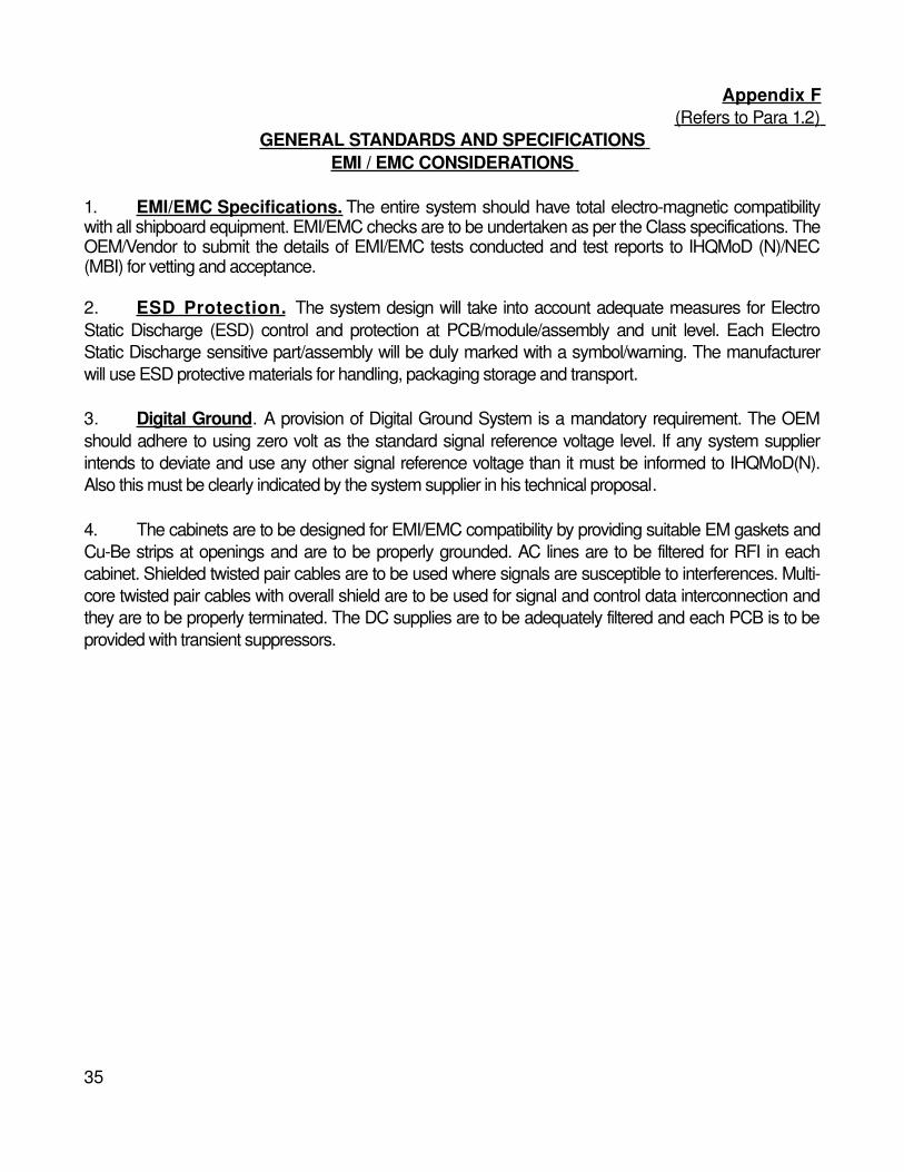
Appendix F(Refers to Para 1.2 )
GENERAL STANDARDS AND SPECIFICATIONS EMI / EMC CONSIDERATIONS
1. EMI/EMC Specifications. The entire system should have total electromagnetic compatibility with all shipboard equipment. EMI/EMC checks are to be undertaken as per the Class specifications. The OEM/Vendor to submit the details of EMI/EMC tests conducted and test reports to IHQMoD (N)/NEC (MBI) for vetting and acceptance.
2. ESD Protection . The system design will take into account adequate measures for Electro Static Discharge (ESD) control and protection at PCB/module/assembly and unit level. Each Electro Static Discharge sensitive part/assembly will be duly marked with a symbol/warning. The manufacturer will use ESD protective materials for handling, packaging storage and transport.
3. Digital Ground . A provision of Digital Ground System is a mandatory requirement. The OEM should adhere to using zero volt as the standard signal reference voltage level. If any system supplier intends to deviate and use any other signal reference voltage than it must be informed to IHQMoD(N). Also this must be clearly indicated by the system supplier in his technical proposal.
4. The cabinets are to be designed for EMI/EMC compatibility by providing suitable EM gaskets and CuBe strips at openings and are to be properly grounded. AC lines are to be filtered for RFI in each cabinet. Shielded twisted pair cables are to be used where signals are susceptible to interferences. Multicore twisted pair cables with overall shield are to be used for signal and control data interconnection and they are to be properly terminated. The DC supplies are to be adequately filtered and each PCB is to be provided with transient suppressors.
35

Appendix G(Refers to Para 1.2 )
GENERAL STANDARDS AND SPECIFICATIONS SUPPLIER’S SCOPE OF SYSTEM SUPPLY
1. The supplier's scope of system supply shall cover the supply of equipment, Installation Material, Spares, Drawings and Documentation, installation supervision, setting to work, testing, on board commissioning, harbour and sea trials of IBS. The supplier is to list down in detail, the deliverables to be provided to the customer at various stages of supply as mutually agreed upon. The complete scope of supply of the system by supplier (depending on whether the subsystems to be interfaced are BFE or to be delivered by the IBS vendor) shall include material as given in succeeding paragraphs.
2. Installation Material . One set of installation material that includes intercabinet cables, connectors, shock mounts, special fasteners, special tools, special fittings etc. which shall be supplied by the supplier.
3. Testing and Tuning Spares . The supplier shall recommend one set of Testing and Tuning Spares for each subsystem, as required for STW, HATS/SATS and commissioning of the system.
4. Special Tools and Test Equipment . The OEM is to provide details of following test equipment that would be required taking into account IN's maintenance philosophy.
(a) Onboard Test Equipment . This should be adequate to meet the requirement of all repairs/ maintenance expected to be carried out onboard ship by the ships staff.
(b) Special test equipment. Specialtotype test equipment shall be made available in the shore base for specific tests/checks on the equipment.
5. On Board Spares (OBS) . The supplier shall prepare the list of OBS (including onboard maintenance tools) based on the Reliability and Maintainability data and taking into account IN’s maintenance philosophy, and shall forward to IHQ MOD (Navy) for vetting during the prebid meeting. The manufacturer should clearly indicate the basis for ranging and scaling of spares. This should include the list of spare parts, tools and accessories, which must be carried on the ship, for preventive maintenance, trouble shooting and quick repairs to ensure no more than 15 minutes of ‘Down Time’ for the system at any given instance. One set of OBS is to be supplied with the system. The complete inventory of system parts including OBS & B&D spares is to be provided in INCAT (Indian Naval Catalogue of Inventory) compatible format in electronic media for ILMS (Integrated Logistics Management system) of Indian Navy, for the management of spares. The supplier shall provide both hard copy as well as soft copy. PCBs offered as OBS should also undergo Endurance Test either on a reference system or on main system. However, in case the qty of PCBs is large, Endurance Test to be conducted on a sampling plan, approved by Insp. Authority. List of all spares/items used in the system with the following classification and details is to be provided to the IN during the prebid meeting:
36

(a) COTS / Non COTS items.(b) RF / Non RF items.(c) PCB or module functionality Processor Function/ Input Output Function(d) Memory Devices(e) Digital / Analogue.(f) With /without embedded software.(g) Hydraulic components /Electrical drives(h) Wet end components.(j) Antenna components.(k) Pneumatic control components.(l) Produced by vendor quoting/ sourced.(m) Repairable by vendor quoting/ repaired by third party.(n) Checked by BITE/Not Checked by BITE.(p) Estimated MTBF in hours.(q) Circuit diagrams available/not available.(r) Fittings like Cooling Fans, Filters, Track Ball, Joystick etc.(s) Consumables like fuses, indication lamps etc.(t) Numbers/quantity fitted the system.(u) Shelf life of spare.(v) Itemised cost of all items.
6. Five Year Base and Depot Spares . The OEM should forward recommended list of B&D spares, tools and test equipment for ICS system for vetting of IHQ MOD (Navy). B & D Spares should consist of spare parts and modules required to replenish depot holdings for a period of five years. These should also contain complete subsystems and assembly spares for the major refit (and thorough checking thereafter) of the system. It should also include exclusive Depot Spares comprising PCBs. The manufacturer should clearly indicate the basis for ranging and scaling of spares. The supplier recommended list of base & depot spares are to be commensurate with the reliability of critical components and modules used in the IBS. The requirement of the projected spares needs to be mentioned. The list of spares should be submitted by the supplier along with the technocommercial proposal for the system. The supplier shall also provide finalised / approved list of B&D spares in INCAT (Indian Naval Catalogue of Inventory) databank compatible format in electronic media. The onboard, base and depot, testing & tuning spares and long term exploitation spares should be indicated with a standard part no for identification and traceability as per Navy’s standards. Order for B&D spares would be placed separately. The classification and details as per Para 5 above, for all approved B&D spares/items used in the system should be provided to the IN during the prebid meeting. Following points in respect of spares of the equipment needs to be mentioned :
(a) The basis of ranging and scaling to be clearly indicated.37

(b) Commitment from the manufacturer for continuous customer and spare support for a specified duration for the life of the equipment.
(c) Commitment to undertake up gradation of the spares if required due to nonavailability of the spares due to obsolescence.
(d) The list should clearly indicate the embedded parts and a softcopy of the embedded codes shall be provided with necessary porting equipment.
(e) The supplier is required to indicate the make and part no. of each item. The details of spares are to be provided in ILMS format (both hard copy and soft copy to be provided).
(f) Base spares recommendation is to cover maintenance / overhaul requirements for 5 years including two refits.
(g) The details of tools and STTE required for carrying out 3rd and 4th level maintenance to be included in the offer.
(h) The supplier shall provide average life of all B & D spares and specify the turnaround time required for repairs/replacement of each spare.
7. Drawings and Documentation.
(a) Firm is required to submit one hard copy and one soft copy of the draft system documents (as per JSG 251) including software documents to IHQ MOD (Navy) for vetting at least 3 months prior to conduct of FATs of the system.
(b) One set of finalised / approved documents should be supplied with the equipment. Additional 6 sets (hard copy) and one soft copy on CD ROM of documents should also be supplied.
(c) Supply of documents will be part of the order and should be costed for in the order.
(d) Documents in CDROM are to be as per Level 4 Interactive Electronic Technical Manual (IETM).
(e) The format and content of documentation should be as per JSG 0251. The vetting and approval of the documents would be done by IHQ, MoD(N)/NTG (Bangalore/Mumbai).
(f) Software documents (if any dedicated OS, Application software or Embedded software has been utilized in the equipment) should be as per IEEE 12207 standard.
(g) The documentation and drawings shall contain complete information for installation, operation, inspection, maintenance, repair / overhaul, testing and trials and should include the following:
Sl No. DESCRIPTION REMARKS
38

(i) Design Specifications The design specification for the System and its role needs to be mentioned.
(ii) User hand book Covering composition and brief description of equipment with block diagram; Technical parameters; Brief technical description with Photographic or graphical representation of each unit; Detailed functional and Operating instructions giving
(iii) Technical manual Covering detailed technical description of each unit with associated drawings and diagrams. It should also include data on Integrated (iv) Installation manual Covering composition of equipment, Cabling diagram and cable specifications, Cable connection schedule, Complete binding data, Installation drawings, List of (v) Maintenance and
Repair manualCovering Instructions on servicing; Planned Preventive Maintenance; on dismantling and assembling of each unit; Faults, their causes and remedial action; Repair, overhaul
(vi) Maintenance Schedule Comprehensive Maintenance Schedules are to be provided along with system. These schedules should cover all the relevant aspects and
(vii) Part catalogue, List ofspare parts, Test equipment
The manual should include(a) Catalogue of parts listing out all the replaceable parts(b) List of On board spares(c) List of B&D spares(d) List of test equipment(e) Service Log Books
39

(viii) Test and Trial schedules(a) Inproduction Test Procedures(b) Engineering, Environmentaland Quality Inspection Procedures(c) Factory Acceptance Trials Schedule(d) Installation Check Schedule(e) Harbour Acceptance Trials Schedule(f) Integrated Harbour Acceptance Trials Schedule(g) Sea Acceptance Trials Schedule
(ix) Instructions on Testing & Tuning and Setting To Work
Containing instructions on Testing and Tuning, alignment, Checking and adjustment to individual parts and of the equipment as a whole.
(x) Software Manual
Software logic for the System.
(xi) System Integration Plan
Containing technical details of all the hardware and software interfaces with the external systems.
(xii) 'As Made' drawingsAs applicable
(xiii) Test data/certificates
As applicable
(xiv) Firmware Support Manual
This will contain the procedure to reprogram all the programmable devices
(h) Configuration control Documents indicating changes in version to be provided.
8. Binding Data . Three hard copies and two sets on CD ROM of the following binding drawings/ documents are to be supplied by the OEM within 3 weeks of placement of order:
(a) Block diagram of the system
(b) Installation documents covering detailed procedure for installation with sequence of activities.
(c) Installation drawings indicating overall dimensions, C.G., weight, maintenance envelope etc of each unit.
(d) Recommended arrangement of devices in nominated compartments.
(e) Inter unitcabling diagram with cables specifications.
(f) Cable connection Schedule.(g) Power supply scheme for the system.
(h) Heat Dissipation of individual units in compartment & in close loop ventilation system, as required for the system.(j) Parts identification list, indicating part no, qty., maker's name, Specification etc.(k) Requirements for support systems such as firefighting, communication, lighting etc.
40

(l) Cable length limitation etc, if any.(m) Detailed foundation drawing including bolting plan.
9. Shipping . All equipment shall be adequately packed and protected with supports to ensure adequate protection during all modes of transportation. Each unit within a package/container shall be clearly marked for identification. The container shall clearly indicate the item description with caution marks, quantity, weight, size etc. A separate document giving details and instructions for storage, preservations, handling and transportation after delivery is to be supplied. The supplier should indicate the delivery schedule, transport, packing, preservation, insurance etc.
10. Authority Holding Sealed Particulars (AHSP) .The DGQA (Navy) would be the AHSP for all the sealed particulars of IBS and associated sub systems/equipment.
11. Preservation, Packaging and Shipping . The stores (including OBS and B&D Spares) shall be supplied in longterm preserved condition that is suitable for storage under tropical high humidity conditions for a period of 24 months.
12. Part Identification List. The IBS Supplier shall prepare and submit a Parts Identification List (PIL) list, showing exploded views of equipment supplied to the Line Replaceable Unit (LRU) level, which shall include exploded view drawings of all equipment clearly showing how equipment is assembled. All equipment and components shown shall be identified by IBS Supplier part number shown in a tabulated parts list provided with the drawing. The PIL shall be organised such that it supports logical retrieval of data. The PIL description shall be part of the Operator's and Maintenance Manual. The PIL shall be included in the CDROM technical manual. (The Parts Identification list that gives the list of items upto LRU level is to be submitted at the time of submission of offer).
13 Integrated Logistic Support Data (ILS). The IBS Supplier shall provide data to support the Indian Navy in the preparation of Logistic Support Analysis. The lists of sub units of the system/equipment, OB Spares and B&D Spares are to be provided in INCAT documentation as given below:
Annexure 1 to Appendix‘G’
(Refers to Para 13)
SPARES MANAGEMENT SYSTEM AS PER INCAT COMPATIBLE FORMAT
41

[IMPORTANT: EVERY SPARE AND EVERY PART WILL HAVE TO BE SUPPLIED WITH A PART NUMBER ( ITEM CODE ) FOR MERGING WITH ILMS FORMAT]
(a) ILMS means “Integrated Logistics Management System”, which has been in operation in Indian Navy.
(b) In order to operate ILMS successfully, Indian Navy wants all information of all equipment & spares to be provided in a structured format in digital storage media, which is compatible to ILMS. The items must include all on board and base & depot spares.
(c) Some of the information required, are to be provided by OEM and details of requirement is stated in following paragraphs.
(d) All equipment / assembly / subassembly / items (kits) must have a part no (item code will be formed out of this part no) and this should be unique.
(e) All manuals, PIL / CPIL & ‘Asmade’ drawings also must have part number. Drawing number may be designated as part number. Description for Asmade drawings should start with “Asmade drawing for……….” to distinguish between item & its drawing.
(f) Part Nos. must not be repeated.
(g) Each equipment drg is to be broken down to assembly, subassembly & item level for assigning part numbers.
(h) In case any item has two separate part numbers, one part number. is to be indicated against field “Substitute part number” and substitute type is to be ‘R’. If any item can be replaced by any another item, the second item is to be indicated against field “Substitute part number” and substitute type is to be ‘F’.
(j) All data are to be filled up in Microsoft Access / Excel.
42

RELATIONAL TABLES AND COLUMNS OF INCAT
Legend
All fields of a table : Key field, No duplicate values allowed.Null : May be left Blank (Other fields are compulsory)Bold Fieldnames : To be provided by the Prof Dtes.Underlined Fieldnames : May be provided by the OEM / Shipyard to Indian Navy.For ANY Code : Use the attached List of Codes or data provided by ILMS for existing Codes.
But if any doubtItem Code : You may use two fields in lieu – OEM’s Name and OEM’s Part Number. Restrict Part Number to char (24).Vendor Code : You may use the Vendor’s Name with the Unique Location Identifier, e.g. BEL Hyderabad.Dealer Vendor Code: Put the details in the Vendor Table, and use the Dealer’s Name with Unique Location Identifier.Country Code : Use Data provided by ILMS. You may use full name of the Country when in doubt.
EXPECTED FROM OEM/SHIPYARD
Item TableItem Code Char (32) *Item Desc Char (60) * Unique identifier put other properties in Characteristic Table.Item Deno Char (3) * Strictly use Codes supplied by ILMS. It
will Mostly be number or set.Months Shell Life Tinyint * 0 (zero) for nonshelf life items.
Spec TableItem Code Char (32) *Spec name Char (30) * Eg, DIN, ISI, BIS, GOST.Value Varchar (20) The number associated with the
corresponding specification name.
Characteristic TableItem Code Char (32) *Characteristic Name Char (30) E.g. LENGTH, MAX TEMP, ADREF 43

(ADDL REFERENCE), DRAWING
Value Varchar (60) Value of the property of Drawing Number with serial number of the part in the drawing.
Substitute Table
Item Code Char (32) *Substitute Item Code Char (32) * One of the items in the item Table.
Use OEM Name and OEM Part number in lieu.
Substitute Type Char (1) As per attached List of Codes.
Eqpt Table
Eqpt. Item Code Char (32) * Each Eqpt is also an item by itself. This is same as Item Code.
Year Obsolescence Char (4) NullHours Estimated Life smallintHours MTBE smallintHours MTBR smallint
EASK TABLE
Item Code Char (32) * Spare part identifier.EASK Item Code Char (32) Identifier for E or A or S or K.EASK Type Char (1) As per attached List of
Codes.Qty Constituent smallint Qty of spare part in that
E/A/S/K.EASK Book Ref
varchar (31) NullQty BD Manufacturer smallint Recommended by
Manufacturer.Qty BD Manufacturer smallint Recommended by
Manufacturer.
Eqpt. Routine Table
Item Code Char (32) *44

Eqpt. Code Char (32) *Routine Type Char (1) * As per attached List of Codes.Periodicity smallint * Numeric Value of Routine Type, e.g.
500,3.
Qty Part tinyint Null Qty of spare part expected to be consumed.
Vendor Table.........................................................................................................................................................Include OEM, Manufacturer, Dealer, Supplier, Trader.
Name Char (50) * Unique identifier, add location for multi Locational vendors.
Address Char (30) *Address Line 1 Char (30)Address Line 2 Char (30) NullAddress Line 3 Char (30) NullCity Varchar (30)State Char (20)PIN Code Char (7) NullCountry Code Char (3)Kompass Control No. Char (9) Null Please capture Tel/Fax/EMail /
Contact person also. See list of Few Additional Tables.
Telephone Numbers As reqd.Fax Numbers As reqd.eMail Numbers As reqd.Contact Persons Names As reqd.
DealerOEM Name Char (50) * Must Exist in Vendor table with full
details.Dealer Vendor Name Char (50) * Must Exist in Vendor table with full
details.
Item Vendor TableItem Code Char (32) *Vendor Name Char (50) * Must exist in Vendor Table.
45

Certification No. Char (30) Null E.g. ISO9000Certification Type Char (3) Null As per attached List of Codes.
Price TableItem Code Char (32) *Price Date Small Date time *Price Ref Varchar (60)Unit Price CC Money Price in Currency Code of only Unit
Qty. and not for Qty Reflected in the last column.
Currency Code Char (3) As per attached List of Codes.Vendor Name Char (50) Unique Identifier of the Vendor.Qty real Null Total Qty for which Price is
applicable.
Codification Scheme for Item
S No
Type of Store Part I Part II Part III
1 Naval Store (DS Cat Number) N GpCl Part No2 Naval Store (Admiralty) N ClGr Pattern No3 E&SP NonRussian E OEM Code Part No4 E&SP Russian S OEM Code Part No5 BEL Stores E OEM Code Part No
Note: 1. S No 1 and 2 are DS Cat and Admiralty Scheme respectively. DS Cat is preferable.2. All E&SP items need to be finally codified as E&SP NonRussian S No 3.3. Make extra efforts & use scheme as per S No 3 for all E&SP items.
46
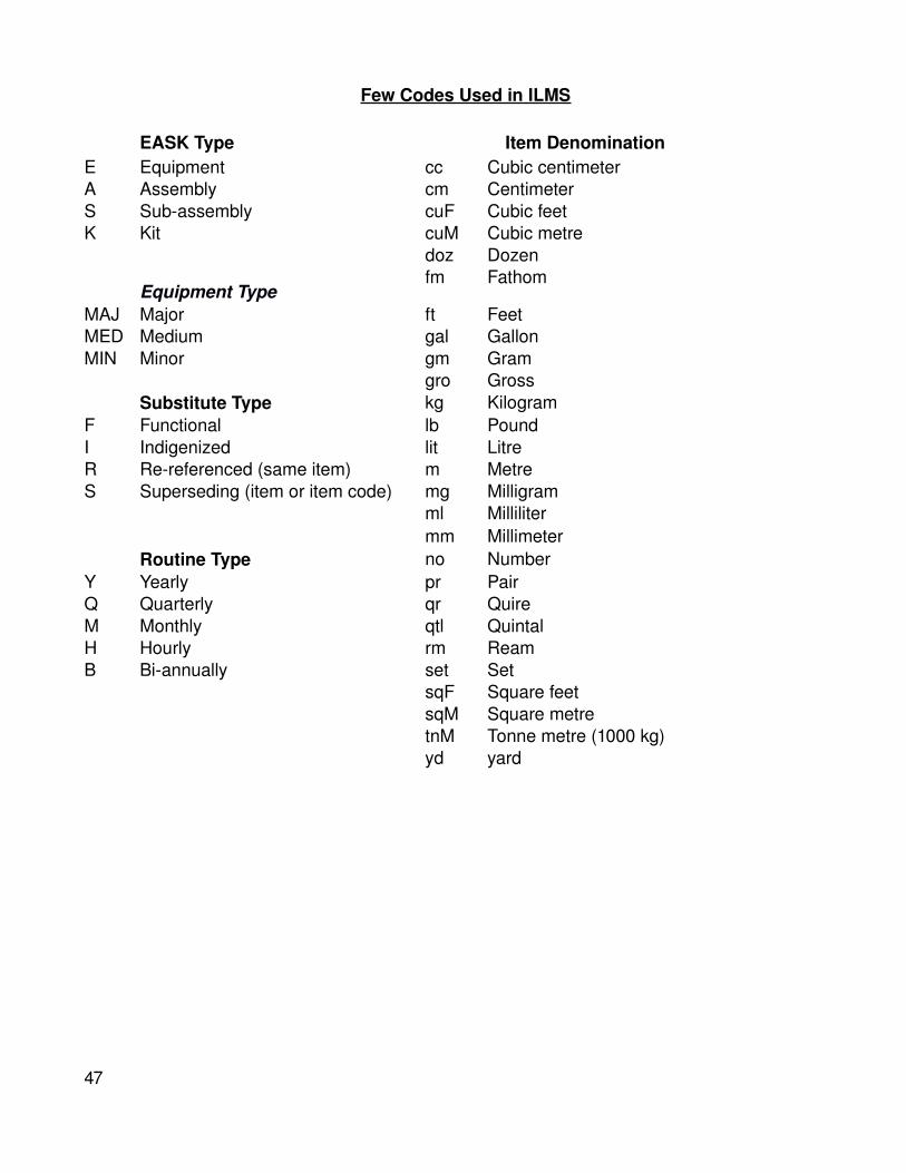
Few Codes Used in ILMS
EASK Type Item DenominationE Equipment cc Cubic centimeterA Assembly cm CentimeterS Subassembly cuF Cubic feetK Kit cuM Cubic metre
doz Dozen
Equipment Typefm Fathom
MAJ Major ft FeetMED Medium gal GallonMIN Minor gm Gram
gro GrossSubstitute Type kg Kilogram
F Functional lb PoundI Indigenized lit LitreR Rereferenced (same item) m MetreS Superseding (item or item code) mg Milligram
ml Millilitermm Millimeter
Routine Type no NumberY Yearly pr PairQ Quarterly qr QuireM Monthly qtl QuintalH Hourly rm ReamB Biannually set Set
sqF Square feetsqM Square metretnM Tonne metre (1000 kg)yd yard
47

CODES USED IN ILMS RELATIONAL DATA MODEL
Currency Code Country Coderbl Russian Rouble BLG Republic of Bulgaria Yen Japanese Yen Bel BelgiumUS$ US Dollar CAN CanadaUK# UK Pound Sterling DEN DenmarkSwe Swedish Kroner FIN FinlandSP$ Singapore Dollar Fra FranceSFr Swiss Franc Ger GernamyRs Rupees HON Hokg KongNKr Norwegian Kroner ITL ItalyMar Malaysian Ringitt Ind IndiaIlr Italian Lira JAP JapanHO$ Hong Kong Dollar Kor Republic KoreaFIM Finland FIM Mal MalaysiaFFr French Franc NOR Norway Eu Euro Currency NRL NetherlandsDkr Danish Korner NZL New ZealandDfl Netherlands POL PolandDug Dutch Guilder Rus RussiaDM Deusch Mark SA South AfricaCA$ Canadian Dollar SGP SingaporeBfr Belgian Francs SWZ SwitzerlandAsh Austrian Schilling. Spn SpainAU$ Australian Dollar Swe Sweden
UAE United Arab EmiratesCertification Type UK United kingdom
BIS Bureau of Indian Standards USA United States of AmericaBS British Standards Ukr UkraineDIN DINISI Indian Standards Institute Price TypeISO International Standard
Organization.A Inflation Adjusted Price
JSS Joint Services Specifications C Central Procurement Price
NAT NATO Specifications D LP (Direct/Local) PriceXXX Miscellaneous E POEP (Estimated)
K Book Price (Kitaab)Q Budgetary Quote Price
Note : More codes can be added should the need arise.
48

SPARE PART DETAILS FOR ILMS COMPATIBILITYBY OEM/ INDIAN NAVY
S.NO.
ELEMENT STRUCTURE BY REMARKS
1. Item/Eqpt. Code Char (32) OEM Consist of OEM Code/Name and OEM Part Number. Part Number to be to 24 Char.
2. Item/Eqpt Desc. Char (60) OEM Put Unique Identifier.3. Item/Eqpt Denom Char (3) OEM Strictly use Codes supplied
by ILMS. It will mostly be nos. or set.
4. Substitute Item Code
Char (32) OEM OEM name and OEM Part Number.
5. Year Obsolescence Char (4) OEM In case of main eqpt. only.6. EASK Item Code Char (32) OEM Identifier for E/A/S/K.7. EASK Type Char (1) OEM Eqpt/Assembly/Sub
assembly/Kit.8. EASK Book Ref. Varchar (31) OEM Book/Drawing reference.9. Qty Constituent Small Integer OEM Incase of spare parts,
number fitted in the equipment, small integer range 0 – 62, 000.
10. Months Shelf Life Tiny integ OEM Zero (0) for nonshelf item.11. Specs name Char (30) OEM DIN, ISI etc.12. Specs Value Varchar (20) OEM Number associated with
Corresponding specs.13. Characteristics
NameVarchar (30) OEM Special Properties like Max
Temp, Drawing etc.14. Char Value Varchar (60) OEM Value of Property, Drawing
reference etc.15. Substitute Type Char (1) OEM Indigenous/Upgrade etc.16. Hours Estimated
LifeSmall Integer OEM
17. Hours MTBF Small Integer OEM18. Hours MTBR Small Integer OEM19. Routine Type Char (1) OEM In case of Main Eqpt. only as
per attached list of codes. (Yearly, Monthly, Hourly etc.)
20. Routine Periodicity Small Integer OEM 5000 Hrly etc.21. Recom BD Spares Small Integer OEM Recommended by mfg.
49

22. Recom OB Spares Small Integer OEM Recommended by mfg.
50

SPARE PART DETAILS FOR ILMS COMPATIBILITY
BY OEM/ INDIAN NAVY (Continued)
S No ELEMENT STRUCTURE BY REMARKS23. Vendor Name
AddressAddress Line 1Address Line 2CityStatePin CodeCountry Code
Compass Control No.
Char (50)Char (30)Char (30)Char (30)Varchar (30)Char (20)Char (7)Char (3)
Char (9)
OEM
Use codes provided above. You may use full name of country when in doubt. Telephone No., Fax No. and Email etc. as required.
24. Dealer Name Char (50)
OEM
Address and other details as per above format. Put the details in the Vendor Table and use the dealer’s name with unique location identifier.
25. Certification Type Char (3) OEM Certification applicable to vendor. As per attached list of codes.
26. Certification No. Char (30) OEM ISO9000 etc.27. Qty Real OEM Total quantity for which price
is applicable.28. Currency Code Char (3) OEM As per attached list of codes.29. Unit Price CC Money OEM Price in Currency Code (CC)
only unit qty and not for total qty.
30. Total Price Money OEM Price for total quantity31. Price Date Small Data
TimeOEM
32. Price Ref. Varchar (60) OEM Quotation / Order reference.
51
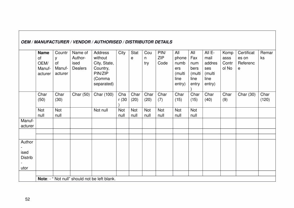
OEM / MANUFACTURER / VENDOR / AUTHORISED / DISTRIBUTOR DETAILS
Name of OEM/ Manufacturer
Countryof Manufacturer
Name of Authorised Dealers
Address without City, State, Country, PIN/ZIP (Comma separated)
City State
Country
PIN/ ZIP Code
All phone numbers (multi line entry)
All Fax numbers (multi line entry)
All Email addresses (multi line entry)
Kompasss Control No
Certificates on Reference
Remarks
Char (50)
Char (30)
Char (50) Char (100) Char (30)
Char (20)
Char (20)
Char (7)
Char (15)
Char (15)
Char (40)
Char (9)
Char (30) Char (120)
Not null
Not null
Not null Not null
Not null
Not null
Not null
Not null
Not null
Manufacturer
AuthorisedDistributor
Note: “ Not null” should not be left blank.
52

53

WEIGHT CONTROL DATA SHEET EQUIPMENT DESCRIPTION
EQUIPMENT NO
COMPARTMENT(IF KNOWN)
LOCATION(IF KNOWN)
SWBD
TOLERANCE PRELIMINARY DESIGN M.T.O. WEIGHED TOLERANCE CODE ESTIMATE (CALC) ± % 1. Weight (Kg)
(a) DRY Kg ± %(b) FLUID Kg ± %(c) OPERATING Kg ± %(d) TEST Kg ± %(e) TOTAL Kg ± %
2. Equipment dimensional data (mm). Indicating C.G. Position
EQUIPMENT PLAN AND ELEVATION
OVERALL SIZE CENTRE OF GRAVITY`A’ (LENGTH) `X’`B’ (BREADTH) `Y’`C’ (HEIGHT) ‘Z’
54

Note:
All offers must include this data sheet duly filled in by the supplier (signed. Dated & seal affixed). All finished items shall be weighed & a certificate shall be provided as per attached sheet. Separate sheets to be completed for each installed equipment.
Origin of `X’, `Y’ and `Z’ to be indicated.
SUPPLIER’S SEAL SUPPLIER’S SIGNATURE & DATE
55

WEIGHT CERTIFICATE
(The form has to be completed by Supplier & to be supplied along with the equipment.)
EQUIPMENT DESCRIPTION EQUIPMENT NO.:
SUPPLIER’S NAME Ref. Drg.
No.
Part No.
ADDRESS
TELEPHONE NO.ORDER NO. EQPT. NO
METHOD OF WEIGHING : Supplier to prescribe Method & Equipment Used :
DATE OF LAST CALIBRATION
SPECIFIED ACCURACY REQUIREMENT
NOTE :
RESULT OF WEIGHING TOTAL EQUIPMENT DRY WEIGHT(Excluding packing, temporary protection etc).
ALLOCATED WEIGHT(Weight estimate agreed by purchaser and supplier based on order specs).
RESULT OF WEIGHING TOTAL EQUIPMENT DRY WEIGHT(Excluding packing, temporary protection etc.)
ALLOCATED WEIGHT(Weight estimate agreed by purchaser and supplier based on order specs).
REASONS FOR VARIATION BETWEEN ALLOCATED WEIGHT AND CERTIFIED WEIGHT :
WEIGHING ADDRESS:
Date :
WITNESSED BYFOR SUPPLIER FOR PURCHASERRepresentative
Signature / Date & Seal
Representative
Signature / Date & Seal
56

DEVIATION LIST
The bidder shall fill in this form for the deviations of their bid from the requirements as stated in the Purchase Technical Specification. If there are no deviations, Bidder shall fill in “NIL” in the Deviation column. Bidder shall sign with date and affix his company seal.
SL No DOCUMENT No & CLAUSE No
REQUIREMENTDEVIATION
WITH REASONS
INDIAN NAVY /
SHIPYARD REACTIONS
BIDDER’S COMPANY SEAL BIDDER’S SIGNATURE & DATE
A ACCEPTED N NOT ACCEPTED C CONDITIONAL ACCEPTANCE
57
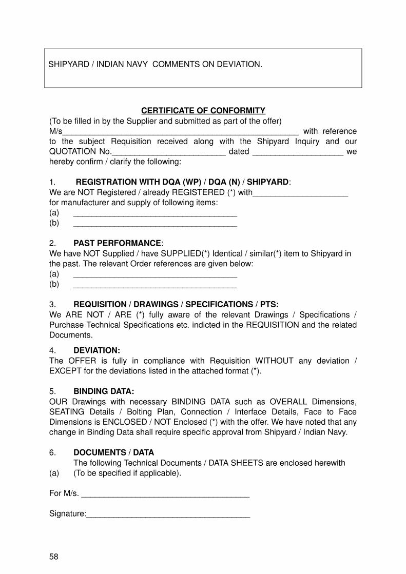
SHIPYARD / INDIAN NAVY COMMENTS ON DEVIATION.
CERTIFICATE OF CONFORMITY(To be filled in by the Supplier and submitted as part of the offer)M/s____________________________________________________ with reference to the subject Requisition received along with the Shipyard Inquiry and our QUOTATION No._________________________ dated ____________________ we hereby confirm / clarify the following:
1. REGISTRATION WITH DQA (WP) / DQA (N) / SHIPYARD:We are NOT Registered / already REGISTERED (*) with_____________________ for manufacturer and supply of following items: (a) ____________________________________(b) ____________________________________
2. PAST PERFORMANCE:We have NOT Supplied / have SUPPLIED(*) Identical / similar(*) item to Shipyard in the past. The relevant Order references are given below:(a) ____________________________________(b) ____________________________________
3. REQUISITION / DRAWINGS / SPECIFICATIONS / PTS:We ARE NOT / ARE (*) fully aware of the relevant Drawings / Specifications / Purchase Technical Specifications etc. indicted in the REQUISITION and the related Documents.
4. DEVIATION:The OFFER is fully in compliance with Requisition WITHOUT any deviation / EXCEPT for the deviations listed in the attached format (*).
5. BINDING DATA:OUR Drawings with necessary BINDING DATA such as OVERALL Dimensions, SEATING Details / Bolting Plan, Connection / Interface Details, Face to Face Dimensions is ENCLOSED / NOT Enclosed (*) with the offer. We have noted that any change in Binding Data shall require specific approval from Shipyard / Indian Navy.
6. DOCUMENTS / DATAThe following Technical Documents / DATA SHEETS are enclosed herewith
(a) (To be specified if applicable).
For M/s. _____________________________________
Signature:____________________________________
58

Date: ____________ Stamp:
(*) Strike out which is NOT APPLICABLE.Appendix H
(Refers to Para 1.2 )
GENERAL STANDARDS AND SPECIFICATIONS INSTALLATION AND COMMISSIONING
1. Installation. Onboard installation of the system will be carried out by the Shipbuilder. The assistance and responsibilities of the OEM include the following:
(a) Coordination with the Shipbuilder for the installation work.
(b) Providing instructions to the Shipbuilder personnel for installation of the system. Cable laying will be done by the shipbuilder before start of the installation activities.
(c) Checking of the cable connections (cold wire test).
(d) Providing details of cable run from Antenna (as applicable) to Below Deck Compartments.
2. SettingtoWork . The supplier shall carry out:
(a) Settingtowork.
(b) Testing and Tuning of the system.
3. FATs and HATs/SATs . The supplier is to offer the system for FATs, HATs and SATs as per IHQ, MoD(N) approved schedule.
4. Factory Acceptance Trials (FATs) . The supplier shall prepare a Factory Acceptance Trials (FATs) schedule. Personnel from Indian Navy will be present during such trials. The schedule should state how the supplier would demonstrate that the delivered system will meet the functional and performance requirements indicated as per Indian Navy's SOTR. The factory acceptance trials procedure shall comprise of
(a) Functional Tests
(b) Verification of design, especially firmware and software
(c) Test equipment used, calibration requirements
(d) Pass/Fail criteria
(e) Expected duration and time schedule
5. The FATs schedule formulated by the supplier should be forwarded to IHQ, MoD(N) for vetting and approval at least 03 months prior to the trials.
59

6. All EMI/EMC and Environmental Qualification tests required need to be completed prior to FATs.
7. Harbour Acceptance Trials (HATs) & Sea Acceptance Trials (SATs) . The supplier is required to provide necessary representative(s) to assist during the following phases:
(a) HATs (procedure to be approved by the Indian Navy)
(b) SATs (procedure to be approved by the Indian Navy)
8. System Performance Responsibility . In case of any irregularities in the operation / performance of the system or nonconformance to specified parameters observed on integration with ships system, the supplier is bound to rectify the defect. The supplier shall ensure complete responsibility of satisfactory operation of the system on board.
9. Interface and Integration . The supplier is responsible for the interfacing and integration of IBS with ship's onboard systems brought out in the chapters of this SOTR.
60

Appendix J(Refers to Para 1.2 )
GENERAL STANDARDS AND SPECIFICATIONS PRODUCT SUPPORT
IN Maintenance Philosophy
1. Onboard Repair/ Maintenance . Onboard repair shall be to replacement at PCB/ Modules (LRU) level. Routine maintenance and serviceability check/terminal performance checks would also be undertaken by ships staff as part of 1st line maintenance.
2. CMC for Repair/ Maintenance . The IBS system being COTS system, all repairs beyond 1st line maintenance will be through CMC contracts with the OEM at Command levels. The CMC should include (but not limited to) following repair works:
(a) PCB/module repairs down to component level.
(b) Repairs/overhaul/refurbishing and testing of major assemblies/ complete system.
(c) Setting to work, testing and tuning onboard ships after major repairs/overhauls.
(d) Repair and 'calibration of BITE and other test equipment.
Product Support from Vendor
3. The supplier should undertake to ensure guaranteed and continuous product support for a period of 15 years from the date of supply of the first system and associated equipment, by way of the following:
(a) Supply of spare parts and materials.
(b) Offering of alternative solutions in the event of obsolescence of the components/technologies, including those bought out or subcontracted.
(c) Continuous upgradation program.
(d) Modifications and repairs.
(e) Provide at least two years notice, in the event of any likely production shut down (only after 10 years of support) to enable procurement of LTE spares.
61

(f) Undertake repairs through Annual Maintenance Contract/Rate Contracts as and when directed by the user / IHQ MoD(N).
(g) Continuous supply of amendments to the documentation.
4. Repair Facilities . Dockyard facilities are to be used for repairing faulty modules. A consolidated test bench to test the modules/PCBs of the IBS system would be required to be provided as part of Dockyard Support Package. Beyond first level maintenance facilities on board, the manufacturer would be required to setup requisite advance level maintenance facilities at locations (Naval dockyards) specified by IN as part of the Dockyard Support Package. Facilities which are required in the Yard as per the IN maintenance philosophy at Para 1 to 3 above, should be projected by the manufacturer, along with the details of manpower required. Further, till such time the Dockyard Support Package is installed and commissioned, provision of AMC and RRC is to be provided by the OEM. The manufacturer will prepare and submit data on maintainability as follows:
(a) Maintainability Program.
(b) Maintainability Prediction.
5. Software Backup . Backup of software used in the system (both on Hard Disks and EPROMs), software reloading jigs and detailed procedure to reload the software is to be provided.
6. Hardware Warranty . The warranty period of IBS system should be for a duration of 24 months from the date of completion of SATs.
7. Training . The Training program objective is to enable the End User Personnel to operate, maintain, and install the IBS system. The Training package is to include the following:
(a) Basic Training . The manufacturer should undertake the responsibility of training naval personnel (including civilian personnel of the yard), as nominated by IHQ/MoD (N), on the exploitation and maintenance of the IBS. The duration of training and number of personnel should be worked out by the manufacturer in consultation with IHQ/MoD (N). Interactive multimedia training modules and suitable software for training on the system be used.
(b) Advanced Training . The manufacturer shall also undertake the training of naval and defence civilian personnel, in carrying out major repairs in the Naval dockyard by using Special Test Equipment/ Special Maintenance Equipment. The training shall include assembling and dissembling of the equipment upto PCB/Microcontroller level.
(c) CBTS. CBTs should cover the system as well as the subsystems and must cater for dual level of complexity, i.e. for operator level and maintainer levels. The CBTs must cover exploitation/operator training, elucidated functionalities of the system (working principle of the system, electrical diagrams, mechanical interaction and functional charts)
62

and include trouble shooting modules. Complete check off list for repair and maintenance to be included.
(d) Simulator Software . Suitable software must be provided for carrying out training at locations designated by IN.
(e) Testing and Calibration . The firm shall provide training to IN and Dockyard personnel on testing and calibration of the system.
8. The Training package for the IBS system is recommended as follows (duration in working days):
SI No.
Course Description No of DurationParticipants (Days)
(a) Operators 7 5
(b) Training staff of IN 3 5(c) Onboard Maintenance personnel for
1st and 2ndlevel maintenance 10 5
(d) Yard Maintenance Personnel 5 5
9. Maintenance . The manufacturer should forward recommended maintenance schedules for preventive and corrective maintenance of the system within three months of placement of order for necessary approval at IHQ.
Appendix K(Refers to Para 1.2)
Appendix L (Refers to Para 1.2)
SCOPE OF DELIVERABLES BY VENDORS FOR IBS (P17A)
Sno. Equipment Quantity Location1 Multi Function Consoles (total 07 nos.) Four Enclosed Bridge
Two Ops RoomOne Chart House
63

2 Multi Function Displays (Total 16 Nos)
Two Enclosed Bridge
four Ops RoomOne Chart HouseOne Wheel HouseTwo Bridge Wings (Ruggedised)One Bridge Top (Ruggedised)One ECPOne CO Day CabinOne CO Night CabinOne NO CabinOne FLYCO
3 GYRO Two4 Nav Radars E/F and I Band Three5 AIS Two6 Echo Sounder One7 EM Log One8 Magnetic Compass One9 AWOS One10 DGPS Two11 Optical Bearing Devices Three One in Bridge and Two Bridge Wings.12 Voyage Data Recorder (Fixed Type
)One 12 Channels {(10 for Voice02 each in
MCR, Ops Room, Bridge Wings and 04 in Bridge)}01 VHF, 01Spare
13 Integrated Captain Consoles Three 02 in Bridge01 in Ops Room
14 Backbone of IBS … IBS own network and associated network switches etc.
Appendix M (Refers to Para 1.2)
SYSTEM MAINTENANCE REQUIREMENTS
1. In accordance with IHQ MoD(N) policy guidelines in vogue, the IBS system will be maintained through AMC with the respective system OEM. The IBS suppliers are required to furnish following details along with the main system bids:
(a) Indicative cost for AMC as % of main system cost.(b) The indicative cost should be separate for comprehensive and non comprehensive AMC along with detailed terms and conditions.(c) Itemised cost of all spares.
64

(d) Turn around time for repairs.(e) The spares should be categorized as per VED rating (Vital, Essential, and Desirable).(f) Recommended stock level based on system MTBF, VED, MTTR etc. The system MTBF, MTTR and maintainability data should be calculated based on the requirements mentioned in MIL HDBK 217F and MIL HDBK 472 procedure5.(g) Test equipment for level 1 and level 2 maintenance.(h) The IBS system will be maintained through AMC/CMC as mentioned above however, for IN’s consideration the vendors should submit details of repair infrastructure required to be established at Naval Repair Yards for level 3 repairs along with cost estimates.
65
Related Documents