State-of-the-Art Review of Solar Design Tools and Methods for Assessing Daylighting and Solar Potential for Building-Integrated Photovoltaics Nebojsa Jakica Politecnico di Milano Department of Architecture, Built Environment and Construction Engineering 9 Bonardi street, Milan 20133, Italy [email protected] www.textilearchitecture.polimi.it Abstract Solar design can take many different forms across disciplines with different methodologies and goals, ranging from acquiring architectural visual effects to assessing illumination for daylighting and solar radiation potential on building surfaces for PV implementation. Furthermore, a capability of solar design methodologies and tools to accurately and time efficiently simulate light phenomena can greatly influence performance results and design decisions. This is especially important in complex cases such as dense urban settings with the significant surface shadowing, and vertical facades including daylighting devices and photovoltaics. Consequently, choosing a suitable approach and tool for each design phase is essential for achieving unique design and performance goals. This paper was carried out within the framework of IEA-PVPS Task 15 – BIPV and it aims to facilitate this decision for all parties involved in solar design process. Here presented, is an overview of almost 200 solar design tools, analyzing their numerous features regarding accuracy, complexity, scale, computation speed, representation as well as building design process integration in about 50 2D/3D, CAD/CAM and BIM software environments. Furthermore, tools from various fields have been analysed in a broad interdisciplinary context of solar design with a particular attention for being used for Daylighting and Building-Integrated Photovoltaics (BIPV) purposes. This approach should open many new perspectives on a potentially wider multidisciplinary usage and interpretation of solar design tools, sometimes well beyond their initial scope of work. Keywords: “Building-Integrated Photovoltaics; Solar design tools; Daylighting; Light simulation; Physically-based ray tracing; Rendering; Complex BIPV simulation; Solar radiation mapping”

Welcome message from author
This document is posted to help you gain knowledge. Please leave a comment to let me know what you think about it! Share it to your friends and learn new things together.
Transcript

State-of-the-Art Review of Solar Design Tools and Methods for Assessing Daylighting and Solar Potential for Building-Integrated
Photovoltaics Nebojsa Jakica
Politecnico di Milano Department of Architecture, Built Environment and Construction Engineering
9 Bonardi street, Milan 20133, Italy [email protected]
www.textilearchitecture.polimi.it
Abstract
Solar design can take many different forms across disciplines with different methodologies and goals, ranging from acquiring architectural visual effects to assessing illumination for daylighting and solar radiation potential on building surfaces for PV implementation. Furthermore, a capability of solar design methodologies and tools to accurately and time efficiently simulate light phenomena can greatly influence performance results and design decisions. This is especially important in complex cases such as dense urban settings with the significant surface shadowing, and vertical facades including daylighting devices and photovoltaics. Consequently, choosing a suitable approach and tool for each design phase is essential for achieving unique design and performance goals. This paper was carried out within the framework of IEA-PVPS Task 15 – BIPV and it aims to facilitate this decision for all parties involved in solar design process. Here presented, is an overview of almost 200 solar design tools, analyzing their numerous features regarding accuracy, complexity, scale, computation speed, representation as well as building design process integration in about 50 2D/3D, CAD/CAM and BIM software environments. Furthermore, tools from various fields have been analysed in a broad interdisciplinary context of solar design with a particular attention for being used for Daylighting and Building-Integrated Photovoltaics (BIPV) purposes. This approach should open many new perspectives on a potentially wider multidisciplinary usage and interpretation of solar design tools, sometimes well beyond their initial scope of work. Keywords: “Building-Integrated Photovoltaics; Solar design tools; Daylighting; Light simulation; Physically-based ray tracing; Rendering; Complex BIPV simulation; Solar radiation mapping”
1. Introduction
Solar design can be generally considered as a process that involves simulation of natural light sources, namely sun and sky. It is used in numerous disciplines whether for artistic and scientific purposes in form of qualitative and quantitative analyses of surfaces and spaces with various spatial and temporal resolution and accuracy. Architects may use solar design tools for photorealistic visual representation helping them achieve specific light effects and atmosphere, emphasising design, objects’ geometry and/or textures. On the other hand, in a collaboration with architectural engineers, architects may use solar design for climate-based annual daylighting simulations to achieve optimally-lit spaces and increase user comfort, balance solar heat gains to reduce energy consumption, estimate solar radiation impact on surface and air temperatures, assess solar radiation potential for BIPV installation, etc. Therefore, the solar design plays a significant role in the sustainable building design process as it influences building cooling, heating and lighting demand as well as carbon footprint, building energy consumption and environment impact. Ultimately, the solar design of renewable energy sources such as BIPV represents one of the essential strategies for achieving Zero-Energy and Zero-Carbon Buildings.
Light simulation capabilities directly influence accuracy of building performance simulation. Moreover, quality and level of integration in a design process make a great impact on a final building design. However, in its early phase of development, physically based light simulations were so complex and computationally expensive for the computational hardware. This has led to numerous simplifications and biased solutions. Since then, light simulations have evolved differently across the fields adapting to the industry-specific demands in order to overcome computational limitations. Most notably, the gaming industry has adopted fast hybrid path tracing algorithms with different level of bias in order to allow more realistic, real-time performance. Visualisation tools have put the focus on achieving photorealistic results implementing many biasing techniques to compute global illumination in time efficient manner. Daylighting simulations used daylight coefficient method, based on a hybrid ray tracing and matrix multiplication, for significantly reducing computation time for annual climate-based simulations with reasonable accuracy. Solar design tools for PV adopted analytical pre-computed Plane-of-Array method for calculating spot irradiance on PV surface and consequently PV energy output.
However, in recent years, increased computational power, especially GPU accelerated process, has allowed dramatic improvements, even real-time performance feedback, in solar design and particularly light simulation, paving a route for a dominance of numerical simulation and physically based ray-tracing solutions over the analytical, empirical or biased solutions. These improvements have allowed most of the solar design tools to expand their features to intervene across fields and eventually lead to integration of qualitative and quantitative simulations in building sector, as it has already happened in automotive and aerospace industries.
However, not all fields that use solar design tools have followed this trend of computational performance boost to improve design workflow and outcomes. This is evident in solar design tools for Daylighting and especially PV simulation where the improvement is moderate. For example, in comparison to the more advanced physically based lighting solutions from other industries such as visualization, which are based on numerical algorithms, irradiance for PV energy calculation still rely mostly on analytical methods that are suitable only for basic PV typologies such as stand-alone and open rooftop solutions with wafer-based PV cell technologies. For other more complex environments that involve shadowing, advanced computation models e.g. ray tracing have to be considered for accurately assessing solar irradiance on PV surface and consequently PV yield. Regarding BIPV, most of the architects still consider their implementation mostly on their sustainability aspirations, economic benefit from feed-in tariffs and/or improving green rating, counting on their energy benefit. However, a multiple nature of the BIPV requires also a necessity for an integrated simulation approach in order to quantify their benefit and ensure proper implementation and economic feasibility. Unfortunately, commercially available tools offer simulation of particular performances to some extent, and yet there is still no 3d CAAD/BIM commercial tool that targets all types of BIPV (not only roof mounted), nor complex BIPV or even aimed for integration in architectural design or EDP. Existing methods for simulating BIPV are mostly custom processes and/or scripts used in research and/or very advanced engineering offices that connect some performances like energy yield simulation, thermal simulation with or without Computational Fluid Dynamics (CFD), or daylighting. Due to the limitation regarding paper’s length, this paper focuses on solar design tools and methods for daylighting as well as solar radiation mapping for assessing BIPV potential. Consequently, topics such as BIPV energy modeling and building energy simulation are covered only to a certain extent where solar design is relevant. Moreover, this review is formed to provide general multidisciplinary framework to a specific, discipline-related topics. These two topics are planned for in-depth analysis in forthcoming reviews with a focus on energy savings and balance in a context of ZEB. They will be using part of the tools described here, relevant to each topic, while adding also dynamic simulation methods and tools. In order to address these topics, an international team of experts in IEA-PVPS Task 15-BIPV has devoted a specific task action on Design and

Performance of BIPV. This paper was carried out within this framework and with a goal to synthesise multidisciplinary knowledge and methods in solar design and present roadmaps for further development of solar design tools to meet the demand of wide range of BIPV solutions, especially facades, considering also Daylighting as one unified approach. According to the task’s vision, these advancements in solar design tools for BIPV and daylighting would enable architect to assess daylighting and BIPV energy production much easier, which will result in larger uptake and therefore acceleration of market growth for both BIPV and ZEB.
2. Previous reviews and surveys
There were numerous reviews in the past covering solar design and particularly daylighting simulation tools, mainly concerning simulation accuracy. One of the first comprehensive reviews on daylighting in buildings was done by IEA Solar Heating and Cooling Programme Task 21 / Energy Conservation in Buildings and Community Systems Programme Annex 29 and Lawrence Berkeley National Laboratory [1]. The main objective was to promote daylight conscious building design through the critical review of algorithms and existing tools as well as developing new ones such as ADELINE. Despite very advanced methods at that time, this review appeared at the early phase of daylighting simulation when computational power was not sufficient for the high computing demand of nascent advanced concepts such as Complex Fenestration System (CFS). Many tools presented there are not in use anymore, while many other have appeared over time. BIM was not developed at that time and CAAD integration was still at the lower level. Furthermore, the review was not comprehensive enough to cover detailed feature comparison.
Later, Reinhart and Herkel performed a state-of-the-art comparison of six Radiance-based methods for the simulation of annual daylight illuminance distributions using daylight coefficients calculation in a single raytracing loop [2]. The results demonstrated that it is possible to achieve acceptable accuracy in an annual daylight simulation method with significantly reduced simulation time.
Reinhart and Fitz conducted a web-based survey on the use of daylight simulations in building design [3]. Survey was realised by collecting 42 different daylight simulation programs that were in use at that time among 187 individuals from 27 countries. Over half of the tools were based on Radiance simulation engine, which confirmed its dominance in the field. However, the review was based on a questionnaire to understand trends, market share, needs, etc. Tools were not specifically indicated, neither their features to provide suggestions for new or to point out advanced features of all tools to existing daylighting specialist.
In 2007, Rogers presented an overview of daylight simulation tools covering 18 different daylighting methods including analytical ones [4]. Probably for the first time, features were presented in the matrix format that offered straightforward overview in comparison to the descriptive methods. Overview provided just a few tools/methods from each of the category of physical modelling, radiosity, forward ray tracing, backward ray tracing, climate analysis, sun path diagrams and other software. However, more importantly, the overview was interdisciplinary much broader than previous ones and included not only daylighting software but also solar design tools in general. In 2008, Galasiu and Reinhart published another web-based survey [3] providing insight into daylighting design practice with an explicit interest in sustainable design [5]. Again, similar information structure was provided, with an exception of including energy-related software. Practitioners clearly showed that quantitative solar design methods are used dominantly only in a design development phase and usually focused on energy savings. In 2009, Kota and Haberl published an interesting overview of the historical progression of the daylighting tools and tools used to assess daylighting in energy performance simulations [6]. Overview illustrated clear distinction between these two types of tools, concluding that energy simulations should incorporate state-of-the-art daylighting techniques for better assessing the solar impact on energy consumption. In 2012, Ochoa et al. gave a review of the lighting simulation for building science [7]. It was mainly based on a literature review and simulation models. Most importantly, it was noted that continuity and dominance of Radiance are good for the community but “focusing on one model might hinder the development of new ones”. Moreover, integration of lighting simulation within general 3D modelling tools such as 3ds max was presented as an interesting direction to address wider design-oriented public. In 2013, Iversen et al. conducted an investigation of the ability of nine daylight simulation programs to calculate the daylight factor in five typical rooms [8]. The analysis was based on daylight factor that was concluded not to be sufficient for a more complex lighting and scene situations. A sample of nine tools was compared in a matrix-based way, but still, the list was not comprehensive enough to cover majority of tools and features.
Reviews [9] and [10] raised the issue of scarcity of current BPS tools supporting the Early Design Phase (EDP). Reviews concluded that currently available Building Performance Simulation (BPS) tools are not compatible with architects’ design methods and needs and are classified not to be ‘architect-friendly’ [11], especially emphasising difficulty of exchanging information between different tools without losing information and what’s more creative continuity [12]. The common point for the majority of BPS tools is that they are suited
for the detailed design phase when most of the design is already defined and they serve to produce performance results and give a rating for one particular solution [13]. The gap between these two performance simulations methods is still vast, and there is a big space for improvement in terms of developing simplified models and tools aimed at EDP. This may explain why architects still widely use rules of thumb in the EDP.
Regarding reviews of solar design tools for PV, there are several studies related to this research scope. Freeman et al. [14] performed validation study for nine PV systems using the most common PV modelling tools: SAM, PVWatts, PVsyst, PV*SOL Expert. Like the majority of PV tools reviews, it was aimed for validation and comparison of tools’ accuracy for free-standing PV solutions, not including shading. In addition, it provided valuable insight into tools’ features in a matrix way. Moreover, the review showed that annual errors for detailed tools felt within ±8%, while PVWatts underestimated performances significantly with the default values, although with the calibration it could match other tools.
Axaopoulos et al. performed accuracy analysis of a different set of commercial tools: TRNSYS, Archelios, Polysun, PVSyst, PV*SOL and PVGIS [15]. Results showed that the PV tools’ simulation generally overrate the Plane Of Array (POA) irradiation and underestimate the energy yield. It is concluded that the main cause of error comes from the model of the PV cell, and it was followed by an error caused by the conversion of the global irradiation on the POA. Moreover, PVGIS data may be considerably inaccurate, particularly if the simulation is performed on a month basis or short time periods. This is the confirmation that more advanced methods are needed for calculation of irradiance, preferably implementing ray tracing methods.
Freitas et al. [16] investigated a wide range of methods, from simple 2D analytical models to more sophisticated 3D representation and numerical analysis coupled with GIS tools, for modelling solar potential in the urban environments quantifying dynamic overshadowing impact on solar radiation availability. The review concluded that solar mapping tools, in general, are capable of dealing with some level of complexity while future improvements in diffuse radiation and energy conversion models are needed.
Finally, the most related state-of-the-art review is carried out within the IEA SHC Task 41 - Solar Energy and Architecture [17] [18] [19]. It was definitely the most comprehensive review done so far, with extensive descriptions for many software tools regarding solar architectural design that includes daylighting, visualisation, BIPV and 3D modelling tools. This was the first time that such, only seemingly different and diverse, topics were considered in the same review. Yet, this should be the only way for solar design to deepen its presence among the professionals by comprehending all interdisciplinary methods and improve integration. Hybrid concepts that emerge out of this integration will be the logical path for improving existing simulation tools’ features and user satisfaction resulting in better and more sustainable building designs. In order to understand the relationship between solar and architectural design, the same task conducted international survey [19] [18]. This survey showed that currently available software and digital tools are not well adapted to deal with the solar strategies including BIPV simulation and more effort is needed to design new or improve existing tools. The review also clearly emphasised lack of “architect-friendly” tools for solar design, despite the variety of choices. Their survey and interviews undoubtedly demonstrated the necessity for the further development of design tools for solar architecture, putting a spotlight on user-friendly tools, preferably integrated into Building Information Modeling (BIM) environment, that present straightforward and meaningful results compatible with the architects’ design workflow. However, despite the broad range of choices, review just marginally touches BIPV, only in term of BIM library element and only for visualisation purposes. Furthermore, overview demonstrated there is no common language for describing what the BPS tools do [20] leading to the confusion among architects unable to distinguish which tool would fit their working method best. Ultimately, all mentioned reviews have not taken into consideration some of the important features for complex BIPV such as spectral rendering, advanced light transport models and layered material definitions. In addition, vast amount of information was presented in a descriptive way so it is hard to make quick conclusions and comparison and find a particular feature.
3. Objectives and methodology
The review aims to overcome limits of previous reviews and provide the most extensive list of solar design tools and features across all industries that use solar design. The main objectives of such a comprehensive analysis of the interdisciplinary topic is to: • describe the most significant features and workflows that are currently available; • explain differences and similarities of objectives and workflows across multiple disciplines; • provide insight into possible limitations and bottlenecks of particular functions, procedures and tools; • map tools with features in visually structured way; • offer quick and effective comparison that could be done in two-ways, per feature/category and/or per
tool/discipline;

• understand market trends and current advancements; • propose potential further cross-disciplinary integration and developments; • target needs and facilitate decision-making of end-users from all backgrounds and level of expertise who
are interested in learning and working in the solar design. Intentionally, the review includes many disciplines that were not subjected within the same research before,
eg. gaming and optical design. Author believes that this approach is essential in order to understand all parts of solar design and simulation workflow as well as light simulation models and concepts. Better understanding of universal cross-industry concepts will consequently lead to better implementation of current tools and demand for their more progressive improvements, especially regarding multidisciplinary approaches and integration.
Paper’s methodology uses data collection that was performed through available official resources provided by software developers in various formats including web sites, manuals, white pages, tutorials, feature lists, etc. In particular, where solar design tool seemed interesting and advanced but feature description was not available, data was verified by mail communication with its developers. Specific feature may be implemented as a standard ready-to-use feature, directly available to the end user. However, feature may be available indirectly if software is open-source and there is a possibility for end-user to change source-code slightly, or available through graph-based parametric interface that enables object-oriented programming. These features are marked as tweaking possible. Otherwise, if feature is not supported, data field was left empty. If there is a doubt on feature due to the lack of available resources, fields were marked as data not provided.
Solar design tools presented in this review have different software structures. Some tools are designed only as collection of executables/modules that can be executed without GUI. Those tools represent core engines that other tools use for calculation while providing GUI. They are presented in legend together with a symbol that is assigned with every tool that uses that specific engine.
The review consists of descriptive and graphical - tables parts. Descriptive part explains all light simulation concepts sorted in categories, while tables provide more structured, compact and straightforward way of presenting vast amount of information on tools and features in the solar design process. They consist of solar design tools sorted in columns while features are listed in rows. Tools and features are sorted into categories according to their original area of development, as some of the tools have become interdisciplinary over time. In comparison to the previous studies, this review should be easier to understand, faster for comparison of particular features or tools of interest, easier for target searching and learning for more end users with different backgrounds and level of expertise. Most importantly, it should facilitate user decisions on most suitable software tool for the particular design phase and project goals. Moreover, solar design workflow has been constantly changing over the years, especially in the last decade, when influenced by new simulation tools provided significant improvements in speed, accuracy, integration in CAD and 3D environment and user friendliness. This review aims to understand these trends and provide guidelines for potential future development by suggesting possible cross implementation among fields in order to develop more robust simulation models that would be able to deal with highly complex topics such as BIPV simulation and daylighting including CFS.
Despite a huge number of tools included, there are still tools that are left out in each category due to the various reasons.
Tools in daylighting/lighting/solar analysis category: Desktop Radiance, ECOTECT, SUPERLITE, Delight, SKYVISION, Lightscape, are excluded from review due to several reasons: They are either not available anymore on the market or their support or future developments are revoked.
Whole building energy tools that did not fit into this review are: Ecotect, ADELINE, EnergyPlus, bSol, ESP-r, EnergyPRO, tsbi3, SUNCODE, EDG II, TRNSYS, ENERGIEplaner, DOE, eQUEST (DOE), VisualDOE (DOE), LESOSAI, BCVTB. Reasons can be found in: poor daylighting simulations, lack of integration into architectural design environment, developed for the detailed design phase, substantial knowledge is required to run the dynamic simulation that is out of scope of architectural design process, out of the market, support and future developments are revoked.
Advanced whole building energy as PV/BIPV tools, not covered here, will be a part of another review where analysed features will specifically suit advanced dynamic PV and building energy simulation.
4. Part I - Solar design concepts and features
Disciplines included here are daylighting (point in time and climate-based), whole-building energy, optical design, visualization/rendering (still images and movies/animations), gaming (real-time interactive visualisation/graphics), and partly PV/BIPV. Analysis of light simulation concepts and tools and their integration in design process are the two major parts of this research that goes well beyond previous reviews and cover the most successful concepts developed across fields. Furthermore, simulation engines/tools are surveyed for their methods of integration in common design software environment in the context of PBD, examined for their

ability to suit different design phases and various scales, from material to urban, availability in different operating systems and pricing. In the following subchapters, only the most important features will be discussed, confronting advantages and shortcomings of different methods. Other features, not described here, but presented in the review, are self-explaining and do not require detailed explanations.
4.1. Geometry
The review considers only tools that support 3D architectural content. Geometry in 3D can be generally represented in two ways: Shell/boundary objects that are represented as surfaces of the object and solid objects that represent objects as volumes. First typology is used more often in visualization and gaming industries while solid representation is used for scientific and engineering purposes in CAD/CAM and BIM tools. Another major difference between artistic and scientific modeling techniques is surface representation. Surface can be represented mathematically as analytical model or through curves, usually Non-Uniform Rational Bezier Splines (NURBS). This model is useful especially for engineering and manufacturing purposes as all surfaces can be described and analyzed with extreme precision. On the other hand, surfaces can be modeled as points in 3D space that are connected by line segments to form a polygon mesh triangles. This polygonal mesh representation was a dominant method for the majority of rendering engines due to the versatility and speed. NURBS were not supported in the early development stage of ray tracing and these surfaces had to be converted in polygon meshes, in a process called tessellation, before being rendered. That conversion could have produced undesirable results, especially in details, with artefacts visible in jagged edges appearance or voids. As CAD/CAM and BIM applications use solid based surfaces, any rendering of tessellated geometries might possibly produce artefacts and errors. While flat surfaces have low error possibility for producing conversion artefacts, freeform and curved surfaces have to be processed carefully, usually increasing density and number of polygons to make artifacts less visible. Until recently there was no rendering algorithm able to work directly on a solid geometry. This has been changed mostly in automotive and aerospace industry software such as Autodesk VRED, Luxion Keyshoot and Lagoa. Rendering directly this type of surfaces allows rendering with a great level of freedom and precision independently of scale. It is expected that rendering directly this type of surfaces will prevail also in CAD/CAM and BIM applications in the future.
4.2. Light transport models
4.2.1. Split flux formula The split flux formula is the simplest and the oldest algorithm used in daylighting studies that was derived
from a manual calculation method established by the BRE (The English Building Research Establishment). This method is consisted of three components of daylight: the direct sky component, the reflections from exterior surfaces and the reflections from internal surfaces. Components are calculated separately and summed to express global illumination in each sensor point. Results obtained are highly approximated and this model has been surpassed by more advanced computer simulation approaches. However, energy simulation engines like EnergyPlus and DOE are still using this method to calculate daylighting factor and energy consumption for lighting.
4.2.2. Rasterization (Scanline) Rasterization can be generally defined as a process of converting or mapping fragments (3D objects, vector
shapes) into the projection plane/image. This process uses a fragment-by-fragment (object order) approach where algorithm loops through each of the fragments, usually triangulated polygon meshes, and determining which pixels in the image it affects and modifies those pixels accordingly [21]. The most used version of rasterization firstly renders the vertices of a face and then interpolates the texture coordinate of that face as a blending of the vertex colours while neglecting specular lighting. This method is used by all current Graphical Processor Units (GPU) and represents de facto standard for real-time computer graphics, particularly games. However, the method is very limited in terms of calculating specular reflections. In order to overcome this issue, rasterization has been recently integrated with a ray tracing in form of a hybrid technique. Due to the rendering speed, rasterization was very common in the 3D animation industry. One example was REYES algorithm [22] that has been used for many years as a core of the PIXAR RENDERMAN before it was replaced by fully ray tracing approach.
4.2.3. Finite element methods - Radiosity Finite element methods (FEM) originate from radiative heat transfer methods [23]. They have found their
application in computer graphics field, in form of so-called radiosity methods [24] [25]. They were developed

mainly to account for non physically based but very time-efficient computation of the indirect illumination. In this process, scene geometry is tessellated into a number of small patches. These patches represent main sources of the global illumination where a global illumination is resolved by computing global rendering equation composed of a linear system of equations describing the light interaction between patches. Initial versions of radiosity were very limited to compute complex geometries, lights and materials of the scene. These versions were created for simple scenes with Lambertian (perfectly diffuse) surfaces and large area light sources. Such restrictions allowed radiosity method to be view-independent meaning that one computation can be reused for rendering images from arbitrary viewpoints. Creating more complex environments has remained a challenging task and this method has been constantly improving adding support for more complex reflections [26], as well as hierarchical methods to address complex geometries [27] [28] and instant radiosity [29]. However, these advancements made the radiosity algorithm much more computationally expensive, while not following real light behaviour, neither providing physically accurate and photorealistic appearance. However, the speed of calculation for simple scenes was still a great advantage. Only recently, methods based on radiosity, as in the case of rasterization, has slowly been abandoned in favour of ray tracing methods.
4.2.4. Stochastic (Monte Carlo) based methods - Ray tracing Ray tracing is a rendering technique based on a geometric (ray) optic light model that calculate light transport
by tracing a large number of rays in a scene - Path Tracing (PT). It originates from ray casting algorithm, developed to solve intersections of the rays with an arbitrary geometry including triangle meshes and mathematical surfaces such as constructive solid geometry models, which trace only one ray per pixel without recursively tracing additional rays needed for global illumination. Ray tracing is an advancement of this approach, originally proposed by [30], that calculate global illumination by means of recursive point-sampling based on rendering equation developed by Kajiya [31]. Rays in ray tracing follow the same principles as light in the real world and therefore this technology is the only one that can be considered physically based [32]. This comprehends that light transport follows energy conservation principles [33][34] with the every light bounce. In other words, at each level of recursion ray tracing algorithm can split ray into components for reflection, transmission (refraction) or in the case of participating media absorption and in particular cases emission, where a sum of radiosity values of the component part must be equal to incident radiosity. Splitting is controlled either by deterministic or stochastic1- Monte Carlo methods [35] [36] [37], essential for all path tracing methods. In a typical Monte Carlo numerical algorithm, random draws following given distributions define a chain of local events characterising the global event and leading to a final state. Therefore, exploring the solution space or events space by repeating random draws numerous times can give an accurate approximation of the solution. The accuracy of this numerical solution depends on the level of model description and number of samples and bounces. Simple and uniform random Monte Carlo sampling would be very impractical and therefore hybrid approach implementing deterministic sampling is always used to facilitate a decision on what to sample, or in other words where to trace the next ray [38]. Over the years, many importance-sampling techniques have emerged. Ultimately state-of-the-art method called Multiple Importance Sampling (MIS) [39] has made physically based rendering computationally feasible today. Particularly important for this research is the optimisation of MIS algorithms for the sampling complex materials, with custom Bidirectional Reflection Distribution Function (BRDF), and illuminated by High Dynamic Range (HDR) Images [40] [41].
Furthermore, shading and light on the surfaces is a sum of components coming directly from the light sources, as specular: reflection and refraction, and as diffuse indirect reflections. First two components can be handled relatively easily while the last one typically requires tracing hundreds, thousands or even millions of rays. Hence, this component is usually subjected to various levels of approximations and optimisations and it is generally considered as a bias. More on this is explained in subchapter 4.3 on accuracy.
Ray tracing can start either from light sources - forward ray tracing, or from a viewpoint or sensor - backward ray tracing or in advanced hybrid methods by combining these two – bidirectional ray tracing. Forward ray tracing methods are commonly used for the optical design of luminaries where it is important to estimate light distribution from the designed luminaries or light transport in optical systems of lenses. This is the ideal version of the light transport model that can simulate all light phenomena as it exactly follows real world light behaviour. However, the main drawback is that it is extremely costly in terms of calculation since for the smooth and pleasant results it has to trace millions of ray recursions while never being able to reach infinite recursions that happen in the real world. Furthermore, accounting specular reflections is a view dependent effect and it had to take into account a view position. Some of the leading forward ray tracing tools are SPEOS, TracePRO, and Photopia. These software are not designed for the general architectural usage and daylighting in general. Only
1 Stochastic method is one whose state is non-deterministic (i.e., "random") so that the subsequent state of the system is determined probabilistically
recently they have started to implement the sun as a light source like in Solar Utility feature of TracePRO and still require some tweaking in order to be implemented as a daylighting tool (Kolås, 2013). Yet, they are commonly used to produce BSDF function for Complex Fenestration Systems (CFS), but their price, closed source code and uncommon software environment for architects and building engineers represents a limiting factor for the broader implementation in building design process.
On the contrary, in the case of backward ray tracing, rays are traced from a camera viewpoint for rendering purposes or from (grid) sensor points for daylighting analyses. Backward ray tracing is much faster method for image synthesis and grid based calculation than forward ray tracing as it only calculates rays reaching the view or sensor point. Since the beginning of the CGI image synthesis, this method has been representing the standard for achieving physically based images for a long time. Radiance engine was one of the first backward ray tracers [42] [43]. Downsides of this approach are represented in the inability to handle complex reflections and refractions of surfaces with specular properties and caustic scattering in transparent materials and participation media. Furthermore, it is not directly suitable in handling properly scenes where light sources are hard to find, i.e. narrow light cracks, light pipes, CFS-like Venetian blinds and caustics.
Finally, both methods have some disadvantages and neither can efficiently solve complex lighting conditions, volumes and materials. Consequently, many hybrid techniques combining these two, have been developed over the years to address these issues, particularly Bidirectional Path Tracing (BDPT) [44] [45] and Photon Mapping [46] [47].
Photon Mapping firstly traces photons from the light sources and store them to be accessible during next rendering phase when rays traced from camera reads stored information for calculating diffuse part of indirect illumination. A progressive version of Photon Mapping has been recently introduced to Radiance to simulate the behavior of Daylight Redirecting Components (DRC), in order to support architects in assessing their performance [48]. This long expected extension will greatly help Radiance users in exploiting all benefits of the bi-directional approach.
BDPT is a combination of forward and backward path tracing. Although capable of dealing with complex situations, the main issue for the basic BDPT is excessive noise. This has been addressed by variety of improvement techniques such as Metropolis Light Transport (MLT) [49] [50], Gradient-Domain Bidirectional Path Tracing (G-BDPT) [51], Energy Redistribution Path Tracing (ERPT) [52], Gradient-domain Metropolis Light Transport (G-MLT) [53], Primary Space Simple Metropolis Light Transport (PSSMLT) [54] and particularly interesting Manifold Exploration Path Tracing (MEPT) [55]. Latter chooses mutation in paths to calculate specular regions and caustics and produce smooth results efficiently. This approach will be beneficial for all daylighting redirecting systems and optically active façade devices, like some BIPV that include light trapping techniques to absorb more light. It is already implemented in some renderers like Mitsuba [56] while others will certainly follow this trend.
4.2.5. Hybrid approaches Worth-mentioning hybrid approaches include a combination of ray tracing with radiosity, or ray tracing with
rasterization. First is used in some daylighting software tools such as EDSL TAS and DIAL+Suite and it offers some advantages of both approaches. An advanced version of this hybrid method uses Multidimensional Lightcuts [57], based on Lightcuts [58] and Instant Radiosity [29], to handle complex illumination and specular materials efficiently. This method is implemented in Autodesk 360 rendering engine used in Lighting Analysis for Revit, Solar Analysis Tool and Green Building Studio. Developers claim that this method is up to 10 times faster than Radiance. However, since indirect illumination is based on Instant Radiosity, a biased method that does not include caustics, which may be a significant shortcoming for CFS and complex BIPV.
Another approach is originally developed for the gaming industry and combines ray tracing with rasterization [59] [60] using very best from both techniques and delivers remarkable photorealistic performance in real time. In this method, rasterisation is used exclusively for antialiasing while ray tracing handles specular effects. Moreover, Brigade and Frostbite offer physically based BDPT that is mentioned as an advanced method able to simulate most complex scenarios. Yet again, other gaming engines still cannot handle caustics. However, the significant speed of the calculation can be very valuable in the early design stage of any lighting design and simulation. The majority of the gaming engines are already commercially available such as UDK Unreal Engine, Unity, Brigade Stingray or Cryengine. Despite the fact these methods are not designed for scientific purposes, some of them like Frostbite demonstrated great accuracy when validated against visualisation industry standard PBR engine Mitsuba [61].
4.2.6. Ray path preview This is one of the most overlooked features that can be crucial in EDP, especially for qualitative inspection
and design of CFS, DRS and shading systems’ geometry, where ray preview can greatly help tweaking the

shapes and improving performances. While present in all forward ray-tracing tools like TracePRO, Photopia, SPEOS and Lumicept, it still represents advanced feature usually unavailable to the broader range of building industry users mostly due to the price tag and different design workflow. Photon Mapping extension to Radiance classic also have the ability to show ray paths [62]. It is recently been integrated into standard Radiance package. However, it will take time for other tools that are based on Radiance to integrate it within their design environment. Still, ray paths can greatly support design decisions in real time as user can immediately sees rays with most intensity and their direction to estimate the influence of light deflection on light levels, a feature very useful for complex BIPV and CFS.
One approach that uses Radiance for analysing Daylighting and clear view of a complex BIPV façade [63] implements mathematical formulas to design and treat geometrical aspects and layout of thin-films stripes and ray propagation through the medium to optimise angle dependency of the system. However, this is one of the rare cases where geometry layout is plain and mathematically defined. For other more complex cases, ray preview represents valuable assistance. Author’s work in this field [64] shows how ray path preview has been used for real-time performance feedback in order to understand how geometry of saw-tooth glass profile influence daylight redirection and PV absorption. Furthermore, preview was used to decrease design search space for later optimization process thus reducing optimization time significantly.
4.3. Accuracy
4.3.1. Bias and consistency Considering complexity of the light behavior and number of photon bounces in real world, only numerical
solution that are physically based have a potential to be accurate to the extent that difference between simulation and real world values are negligible, in other words error approaches zero. There is often a misconception over the usage of terms un/biased and in/consistent. Unbiased is often used to represent particular rendering engine as physically accurate solution. However, this may not always be true as all ray-tracing solutions are biased to certain extent in a way that none of the tools can match number of bounces that happens in reality. Generally, all solutions have to overcome this limitation by introducing some techniques that reduces number of photons/rays and their bounces or give importance to some ray directions in order to generate results faster. Difference between unbiased and biased methods lies in the ability to produce correct results on average when combining multiple iterations. Unbiased will always produce results and errors that are predictable and proportional to the variance of the estimator and computation time [65]. Biased methods implement reasonable simplifying assumptions that improve efficiency. All techniques based on catching data of diffuse indirect illumination component are generally considered as biased. Additionally, adaptive sampling and value clamping using threshold to decide whether to continue a path may also considered as a bias. However, for the purposes of this paper and solar design tools in general, it is more important to differentiate consistency. Consistent method assumes that with an increase of computation time the approximation error approaches zero. This practically means that consistent method can reach any level of accuracy can by increasing the number of photons, reducing or decreasing noise threshold. Therefore, only techniques based on path tracing, bidirectional path tracing, volumetric path tracing and Metropolis light transport, sometimes called brute force methods, can be considered both unbiased and consistent. They do not use any pre-computation for computing diffuse indirect illumination component and catching data, and consequently their convergence to the unbiased final solution is significantly slower than others that use pre-computation. However, these techniques may also be biased if bounces of light are limited (photon bounces are stopped before they are completely absorbed or left the scene) and if caustics are not included in the computation.
Irradiance caching [66], originally implemented in Radiance, can be considered as a high-quality biased but consistent acceleration technique for computing diffuse indirect illumination component and it is widely used in many ray tracing engines and hybrid methods such as photon mapping. Its main advantage is that it incorporates the beneficial properties of radiosity methods while retaining the generality of Monte Carlo approaches.
Since it is impossible to distinguish accuracy of particular biased and unbiased implementation and solution generally, as tools offer different number of options to control bias, this review will therefore differentiate only all previously described consistent methods over non-consistent ones such as splitflux, rasterization and radiosity.
4.3.2. Validation In order to evaluate the accuracy of the light simulation tools, the CIE technical committee 3.33 defined a set
of test cases and methods [67]. Validation of these test cases has been shown in [68]. This research showed the usefulness of the proposed methods and cases in assessing the accuracy and the capabilities simulating different aspects of the lighting propagation by representing strengths and weaknesses of the light simulation tools.

However, it is noted that proposed test cases are not sufficient to address other complex lighting and daylighting cases. Various proposals have been made to improve evaluation of global illumination methods such as [69]. Reinhart [70] also proposed: “A complementary set of more complex daylighting test cases that compare experimental measurements in “real” daylit spaces with simulations is necessary to help design practitioners to develop a feeling of how close a lighting simulation program, operated by a knowledgeable user, can model reality”. Physical validation of global illumination methods: measurement and error analysis
Additionally to CIE validation test cases, other datasets are available such as ones proposed by The British Building Research Establishment (BRE) and National Research Council Canada (NRC). The latter one is used to validate popular mental ray rendering engine within Autodesk 3ds Max Design 2009 as well as the Daysim 3.0 [71, p. 0].
4.4. Computation
Computation of light transport has always represented one of the most important features for light simulations. Lack of computational power during the first period has forced all methods to develop simplification models to be able to perform simulations in a reasonable time. Ray tracing, as ideal light transport version, has been waiting for a long time to become a dominant method. Ray tracing algorithms have firstly been designed exclusively for Central Processor Unit (CPU). Furthermore, early simulations in 80’s were needed several hours or even days to obtain results. Single-core CPUs have followed Moor’s law and progressing until they reached theoretical limits in speed of about 4GHz in 2005 due to the overheating caused by high frequency. Since speed was limited, the only way to increase efficiency was to use parallelism. Various strategies have appeared for multi-node parallel rendering such as replacing single-core with multi-core CPUs implementing hyper-threading, connecting CPUs and creating render farms over the local network, Cloud [72], or directly as “render slaves”. However, this was not efficient and economic way of parallelism and improving efficiency as price vs. efficiency was directly proportional.
With the rapid development of GPU capabilities and speed, simulations have started to be performed also on GPU [73] [74] or by combining CPU and GPU. In order for GPU to become general-purpose hardware, specific drivers have to be created in form of APIs. NVIDIA uses its own API – CUDA, while AMD cards work with OPENCL APIs. Contrary to the OPENCL, CUDA is not card specific and works with all CUDA-enabled cards. Although CPUs are created as fast low latency solutions, initially optimized for single tasks, GPUs are designed for massively and embarrassingly parallel and independent tasks [75], such as calculating the color of each pixel on the screen [76, p. 1]. Luckily, ray tracing is one of these types of tasks and GPU based renders have started to emerge rapidly. Efficiency vs. cost ratio is much better in comparison to the CPUs, as for the small increase in price, performance can be increased multiple times. So far, the main barrier for GPU based renders has been memory that can be stored and accessed, because complex scenes require more memory, and therefore they could not have been rendered with GPU before. This was solved recently with the introduction of Pascal and Polaris architectures by NVIDIA and AMD respectively, as they provide cross-GPU memory access (NVIDIA NVLink) at very low latencies. Another advancement that will enable boost in efficiency is High Bandwidth Memory (HBM) configuration that stacks regular memory chips on top of one other and enables bandwidth of up to 1000GB/s. One approach that time-efficiently combines several methods relying only on GPU to perform unbiased physically based rendering is presented by Van Antwerpen [77].
Cloud-based computing has emerged with the dramatic increase of the internet speed over the past years. It allows hardware-independent solutions where there are no limitations of either computation power or hardware. In these terms, simulation is possible even on mobile devices and tablets. This is a major breakthrough for all the industries related to light simulation as it finally allows enormous capacity to perform simulations in real time. Alternatively, cloud computing may be used for numerous simulations of different solutions in the optimization process. One approach that used parametric modelling and optimisation of energy performance for hundreds of thousands of solutions in the cloud is shown in [78].
Independently from hardware, ray tracing solutions have recently started to implement progressive rendering techniques [79]. Over the years many different methods emerged to follow this concept based on interactive path tracing [80] [81]. The great benefit of this approach is that simulation can start showing rough results immediately in real time while accuracy increases over time. Simulation can be concluded by reaching previously set noise or time threshold, or it is up to the user to decide when to end the process. Recent development in progressive rendering for improved global illumination shows great improvement in speed [82].

4.5. Spectral rendering
Although a light spectrum covers huge range of wavelengths, particular interest for this research represents parts of the spectrum with a wavelength ranging from 280 to 1800nm: Near Ultraviolet (NUV), Visible (VIS) and Near Infrared (NIR). This range almost matches with the solar radiation spectrum AM1 (280-2500nm) that represents the standard for testing PV cells and modules, as all of the PV cells spectral response curves fit within these boundaries. However, common light model used for daylighting and visualization purposes covers only VIS part of the spectrum (380-700nm), neglecting light wave properties and NIR, NUV spectral part. This can cause inaccuracies, particularly when calculating irradiance values on surfaces integrating over only VIS spectrum, while only approximating NIR and NUV parts. PV output of the cells with significant spectral response in this part, such as crystalline Silicon (c-Si) or multi-junction, can be underestimated. Moreover, due to the huge computational expense at the time they were developed and in order to reduce the time required to create an image, daylighting and visualization tools further approximated handling of the visible spectrum information into tristimulus values RGB (Red, Green and Blue channels) [83].
RGB colour model is highly hardware dependent as it was designed for displaying images on screens. This model alone, neither other models such as CMYK, HSV or hardware independent CIE XYZ, is not suitable for accurate colour representation in rendering [84] due to the limitation of luminance and chromaticity output displays. RGB model neglects a number of phenomena important for truthfully accurate visualisation and simulation, like metamerism, wavelength dependent coloured scattering, dispersion, polarisation, fluorescence or spectrally selective absorption in participating media. Metamerism can cause the apparent colour of an object to vary significantly under different illumination spectrum. Furthermore, if renderer uses RGB model during calculation phase, results are produced with a shifted color space [85]. Same paper proposed a simulation alternative for improving physical accuracy of trichromatic coding schemes by combining a spectral rendering method with RADIANCE. They proposed N-step method where the solar spectrum is separated into N consecutive wavebands that form N channels used in simulation, rather than the standard three channels (RGB). Paper demonstrated that in order to achieve higher luminance accuracy levels of 5-6%, in comparison to nearly 20% with RGB models, spectral rendering is required. They found that 9-step is a reasonable approximation of the visible spectrum that produces accurately both luminance and color. Furthermore, all calculations are hardware-independent and conversion from XYZ to RGB space takes place only to actually displaying an image.
Considering PV material characteristics and especially semi-transparent PVs, it is important to take into account light transport in participating or volumetric media (defined in CG as absorbing homogeneous material) that follows Beer-Lambert’s law and can also have wavelength-dependent scattering distributions [86]. It is usually calculated in a biased way, but there is an unbiased method as well [87]. A new efficient method to model complex lighting in participating media use Progressive Photon Beams (PPB) is presented by [88]. Absorbing only some fraction of radiant energy per unit length can result in distance-dependent spectral colour shifts. Consequently, light spectral power on the outer side will be modified compared to the incident one. Since PV cell can be considered as this type of media, where wavelength-dependent absorption is crucial for determining electricity yield from External Quantum Efficiency (EQE) and Internal Quantum Efficiency (IQE), spectral rendering embodies preferable choice. Particularly, in a case of semi-transparent and/or colored BIPV cells such as Dye-Sensitized Solar Cells (DSSC), or electrochromic glazing, color of the dyes in BIPV or chemicals in electrochromic glazing can shift light spectral power causing great offset in Color Rendering Index (CRI) of the indoor spaces [89].
Regarding thin films, highly nonlinear and wavelength and angle dependent refractive index of physically-based reflectance models, described by Snell’s law and Fresnel formulas, can have a quite strong influence on the dispersion of the reflected and transmitted light on an interface, producing saturated colours from unsaturated ones. Research by Tandianus et al. presents an efficient way to compute spectral caustic rendering of a homogeneous caustic object based on wavelength clustering and eye sensitivity [90]. In addition, it can be essential for simulating micro or nano-sized antireflective coatings used in Low-e glazing or as a top layer in BIPV. This is the strongest wavelength-dependent effect and also the hardest to handle properly since it results in a direct dependence of ray direction on wavelength [91]. Low-e glazing, despite excellent solar heat gain performance, have a side effect evident as urban light pollution. Due to the spectral selectivity, especially in IR part of the spectrum, these types of glazing almost completely reflect IR rays toward urban surrounding causing excess radiation and increasing the effect of urban heat islands. Furthermore, if building shape contains concave shapes as in cases of skyscrapers so-called “Valkie-Talkie” in London and Hotel Verdara in Las Vegas, consequences may be fatal. Concave building shape of “Valkie-Talkie” produced concentrated light beam, also called “Death Ray”, causing a light spot with about 10 times more intensity than average and temperatures exceeding 100°C [92]. Therefore, spectral rendering such as one proposed by [93] represents the only way to directly handle full spectral information during rendering, accurately perform simulations, colour rendering
results [94] [95] and estimate impact and light pollution that these types of glazing can produce to the environment. Radiant flux integral should be calculated from full spectral data, while tri-chromatic linear model is all that is needed only for the perceptual representation of a colour, where the last phase should convert spectral to RGB values for an image to be represented on an RGB monitor. However, despite promising trials to account for some of this spectral effects in three-component light models optimised for rendering [96], RGB model has never been designed nor ever be able to perfectly simulate spectral light phenomena and produce highly accurate results.
Spectral rendering can be also very valuable in emerging frameworks for evaluating non-visual effects of daylighting on human comfort, metabolism, health, well-being and productivity , especially concerning human circadian rhythm [97] [98] [99]. Inanici et al. [100] used previously described multi-spectral N-step method based on Radiance to demonstrate its ability and benefit for calculating circadian daylight performance.
Considering the computational power, when it was proposed more than 20 years ago, spectral rendering was overkill even for the most powerful systems, and meanwhile RGB has become a standard light model for rendering. However, with the enormous increase in the available computational power since then and further improvements and optimisation of the original method [101] [102], the additional computational expense of a full spectral simulation in comparison with an RGB model is almost negligible. As also noted in [17] spectral rendering is a promising development for future study of special coating and/or glazing materials widely used in solar architecture. Therefore, it can be concluded that the spectral rendering has become a reasonable and necessary step forward in visualisation, daylighting and BIPV simulation.
4.6. Types of simulations/analyses
The versatility of the physically based approach has found support in both CG art field (rendering) and architectural/building/lighting engineering field (daylighting design) from the early years of Radiance development. At that point in time, it represented a significant breakthrough, especially for the daylighting design after its numerous validations [43] [103] [104] [105]. Later improvements have been made to allow annual and climate based daylighting modelling using daylighting coefficients or sky mixing methods. Daylighting coefficients methods is originally proposed by Tregenza and Waters [106], and implemented by Reinhart and Henkel into Radiance as a DAYSIM extension [2]. Sky mixing methods interpolate values under a range of skies from clear to overcast for different points in time in a year. Support for the simulation of CFS and dynamic shading in form of three-phase and five-phase methods that use Bidirectional Scattering Distribution Function (BSDF) xml file [107] has also been implemented and validated recently [108][109]. Nevertheless, due to the computational time needed to calculate all of the points in time steps during the whole year, these methods implement point grids to collect illuminance data. This was a necessary approximation back then when accessible computer power was very low comparing to those nowadays. Since some current solutions in CGI already works in real-time, future directions will, therefore, increase the resolution of these grids and calculate annual daylight metrics as an image, being able to take into account also qualitative, visual and non-visual aspects of daylight.
Radiance engine’s lack of appropriate GUI has limited its wider acceptance, especially among end-users and very vibrant and progressive CGI community. GUI applications that use Radiance engine rarely implement most of its features. Despite being designed for both qualitative and quantitative analyses, over the years its relevance in visualisation field has been constantly decreasing and eventually being overtaken by the majority of CG rendering tools available nowadays. Nevertheless, it is still considered a state-of-the-art method for daylighting simulation and most of the available daylighting tools use it as a ray-tracing engine. On the other hand, the majority of the visualization tools almost completely abandoned quantitative aspects of the simulations including daylighting and put a focus only on a visualisation part. Yet, according to trends, majority of tools that aim for physically based approach would sooner or later strive to unite artistic and scientific needs into versatile cross-industry packages, as it has already happened in automotive and aerospace industries and their cutting edge software like SPEOS, VRED etc.. Dubois and Horvat [17] also recognized that this is certainly an area which needs much development in the future. It is just a question of time before this approach becomes common in architecture/building industry.
Radiance pace in this development comparing to the other visualisation and gaming tools is very slow. It is likely that integration of Radiance concepts regarding annual daylighting with other advanced rendering tools and engines into hybrid approach will represent a step forward in the future solar design and particularly daylighting and BIPV design and simulation. Methods such as Accelerad [110] that extend Radiance classic engine to work on GPU with Nvidia Optix engine replacing traditional Radiance rtrace, or Photon Mapping [48] with its EvalDRCtool for the annual characterization of DRS [111] that adds bi-directional capabilities, will, hopefully soon, bring daylighting simulation necessary improvements.

Lastly, one of the promising approaches uses Precomputed Light Transport (PLT) for rendering complex scenes with a full indirect illumination in real-time and the ability to dynamically control local lights and viewing directions [112]. The approach uses radiance regression function to train the neural network in pre-computation phase to allow real-time rendering of the indirect illumination of the whole scene under different lighting and viewing conditions. The system focuses on achieving real-time rendering without sacrificing any global illumination effects resulting in high accuracy. However, the system still needs reasonable time for pre-computation phase, but authors claim that this can be reduced significantly. This could open up new real-time approaches to the annual daylight modelling.
4.7. Simulations’ representation
Radiance engine has been designed as an extendable collection of modules/executables for UNIX without GUI allowing it to grow gradually by including many interesting concepts over time. Its robust light transport model supports calculation and storing colours as RGB values and illuminance as radiance floating point values. This approach is extremely important for later extraction of various types of analysis out of a single simulation run. In this way, many various modules have appeared over the years to interpret simulation results. This research will consider analyses that can be generally divided into several groups: qualitative – visualisation/rendering and human vision, and quantitative - photometric (illuminance/luminance), radiometric (irradiation/radiation) and colorimetric. Color information for the purposes of visualization can be extracted from a high-dynamic range images in floating-point 32-bit format to be represent in 8-bit mode, suitable for displaying images on screens. In case of high contrast dynamic range of the scene, tonal-mapping module such as Radiance pcond compresses pixel values from very dark to very bright areas using variety of mathematical techniques to determine appropriate exposure. It can simulate effects such as veiling glare, loss of focus and color sensitivity in order to evoke visual perception of the human eye in photopic, mesotopic and scotopic conditions.
On the other hand, modules for photometric and radiometric analyses neglect colour information, and extract only RGB intensities per channel, integrates and convert these values to radiometric and photometric quantities, in desired units. Due to the high dynamic range of these images and colour independence, these analyses are shown as false-color images. Although very basic, but very important option from the scientific and engineering point of view for quantity and quality of light/daylight and irradiance/temperature for BIPV, this option is neglected by many CG visualisation tools. However, some visualisation tools implement this option within their frame-buffer channels also called render passes/channels. As this type of visualization tools are used by architect more often than daylighting tools, the integration of quantitative analyses in the design process could be much easier if approached within visualization tools.
Most of the 3D visualisation software support high-dynamic range output of illuminance values via lightmaps or in other words illuminance values baked to a UV texture. These maps can then be converted to irradiance ones and integrated over the surface area to obtain a unique value for the purposes of PV assessment. In addition, lightmaps can be a great way to evaluate disposition and homogeneity of the illumination on the surface. Lightmaps creation is not dependent on light transport models and techniques. In addition to lightmaps, another approach in form of interactive lighting analysis grids was proposed by LightWorks and their iRay+ tool. These grids can be exported either in text format or presented as texture displays and shown directly within 3D environment. This method allows architects to explore lighting levels on a range of lighting grids through a model visually.
As already discussed in spectral simulation part, accuracy of photometric, radiometric and colorimetric analyses could be improved if the calculation model and storing data is spectral-based, rather than RGB. RGB model should be used only to extract color information for displaying final images.
4.8. Light sources
4.8.1. Natural Analytical sky models are used for parametrically describing complex sky luminance distribution as more
simple sky conditions. An analytical formula able to describe general luminance sky distribution was originally proposed by Perez et al. [113], commonly known as Perez All Weather Sky model. Slightly modified version of this formula, with tabulated parameters, was adopted by the International Commission on Illumination (CIE) and International Organization for Standardization (ISO) to create a joined standard [114] by refining all previous standards. It collected 16 different sky models describing luminance distribution for different atmospheric conditions, including models for overcast skies developed by Moon and Spencer [115], varying from clear sky to overcast with different luminance turbidity. Standardised sky luminance distributions are very important for daylighting analysis and comparative evaluation of alternative daylighting design options either through

computer-based simulations or through physical model testing in sky simulation facilities that can accurately reproduce these skies. For the purposes of daylight simulations, Radiance extension utility gendaylit implements these models. The most commonly used are CIE clear and overcast skies, while Perez All Weather model provide increased accuracy in absolute results. Limitation of these models from the BIPV simulation point of view is that they describe only the luminance distribution and neglect color as well as spectral (wavelength) information. Furthermore, these analytical models of sky luminance distribution deal only with the sky dome's appearance and exclude the solar disc. Therefore, they cannot be directly implemented for renderings without adjustments, but they are still used as a standard for daylighting simulations to provide illuminance values. Nevertheless, some of the rendering engines like Mentalray and Vray offer CIE and Perez sky definitions. Later developments were focused to account for physically based coloured skylight models, that are directly useful for rendering purposes - single scattering model [116], multiple scattering model [117]. Preetham et al. [118] developed a model based on the Perez All Weather model and Nishita model, that analytically solve sky luminance distribution. This model currently represents the de facto standard analytical model of coloured sky-dome radiance.
In their review, Zotti et al. [16] carried out experimental validation of Preetham and CIE models and pointed out on some issues of Preetham model, particularly in low sun position, suggesting improvements using spherical harmonics as proposed by [119]. Preetham et al. later improved this model by employing a separate analytical formula for adding a solar emitter of appropriate radiant intensity to account these issues. Although it produces sensible results, it still suffers from a range of numerical and accuracy-related problems. Bruneton and Neyret [120] presented an accurate method to simulate the skylight in real time that takes into account many effects of the light scattering such as Rayleigh and Mie multiple scattering, the daylight and twilight sky colour and aerial perspective. Hosek and Wilkie [121] [122] [123] went further in improving Preetham model developing separate fitting for each waveband by using look-up tables, accounting also for ground albedo and polarisation, resulting in higher level of precision and realism especially during sunsets and high atmospheric turbidity setups. Later, they improved their model and implemented a precise solar-Radiance function for direct solar radiation that exactly matches previous skylight model and produces reasonably accurate results [124]. Comparison between these two models made by Kol [121] showed that Hosek-Wilkie generally outperforms the Preetham model in terms of result accuracy, but it is 30% slower than the Preetham model simulation due to the searching of a look-up table. Although developed very recently, Hosek-Wilkie model has already been implemented in some tools like Luxrender, Corona, Cycles, Arnold, NOX, Mitsuba and Vray. It will certainly replace Preetham as a standard model.
When considering capturing of a spectral sky radiance distribution, which provides both spectral and spatial information about the radiation field, Pissulla et al. presented a methodology and calibration procedures for five instruments capable of making such measurements [125]. Four of these instruments were based on double monochromators scannng each wavelength in turn, and one was based on a single monochromator with a charged coupled device (CCD) allowing the recording of all wavelengths simultaneously. Measured results deviated from 3% to 35% due to the uncertainties arising from different calibration procedures and input optics with different FOV. Similarly to their, Tohsing et al. created their own hemispherical sky imager (HSI) made of commercial compact CCD camera equipped with a fish-eye lens to capture spectral sky radiance distribution from all-sky images for the complete spectrum in the visible part (380–760 nm). They used non-linear regression technique to obtain a spectral sky radiance from RGB values with a deviation of less than 20 % for all sky conditions comparing to the measured radiance distributions obtained by a CCD spectroradiometer [126]. Another approach that involves capturing high dynamic, spectral, and polarized natural light environment is shown in [127].
The most recent and comprehensive review and framework for an experimental comparison study of solar and skydome illumination is presented by Kider et al. [128]. They compared several state-of-the-art solar/sky model and indicated their strengths and weaknesses, and presented deviations from measured results. They concluded that brute-force models like Nishita and Haber are excellent in accounting for the direct solar and scattering parameters but they are not suited for time efficiency and real-time graphics since brute force path tracing is considerably slower than pre-catching methods. On the contrary, Preetham, Hosek and Bruneton path-traced real-time models produce very fast results but at the expense of accuracy in favour of speed. These balanced approaches should represent ultimate user choice for the majority of tasks.
In addition, Kider et al. proposed their own spectral data-driven sky model built from the spectrophotometer measured data. This illumination model can find its application in rendering, daylighting, or thermal studies since the illumination information spans across a spectral range of 350nm to 2500nm, as opposed to RGB trichromatic visible spectrum of a HDR image. This would have enormous benefits to the wide community of both academia and practitioners in producing more physically accurate simulations. Unfortunately, the model is still not available for the public but its release is expected soon. Furthermore, since both complex analytical and
data-driven models are costly to compute interactively, Satilmis et al. proposed machine learning approach to compactly represents sky illumination from both existing analytic sky models and captured environment maps [129]. The model is proved practical as a generic approach for both offline and real-time applications.
Considering commercially and publicly available methods, currently the most popular method for representing luminance sky distribution in CGI remains HDRIs. They are mostly used for artistic image-based lighting visualisations due to the high realism, but they can be used also for environmental validation purposes to represent real sky luminance distribution for daylighting purposes [130] [131] [132] and semi-transparent BIPV [133].
In conclusion, since spectral properties are very important for BIPV simulation latter models based on Preetham are more suitable than classical Perez model, while improved version of Hosek-Wilkie model represents currently the most suitable choice for accurate color representation and visualization, as well as simulation of BIPV and daylighting within 3d CAD environment.
4.8.2. Artificial Light distribution from the artificial light sources is defined by the spatial luminous intensity data presented in
photometric files. There are two photometric data files types currently used. First, called IES, and most used one is proposed in 1986, and later updated in 1995 and 2002, by the Illuminating Engineering Society of North America (IESNA) in the standard LM-63-86 on “IES Recommended Standard File Format for Electronic Transfer of Photometric Data.”[134]. Another format is EULUMDAT (also known as LDT, after its file extension) and it is mostly used in Europe, but it has remained largely unchanged since its introduction in 1990.
4.9. Simulation scale
4.9.1. PV cell and material scale Our present understanding of the light behaviour is based on hierarchical models where lower levels are based
on simplification assumptions. Quantum electrodynamics or quantum optics presents the de facto highest level of this hierarchy, followed by electromagnetic and wave optics. Optical modelling and simulation for multi-layered photovoltaic devices, such as thin-film, generally uses a wave-based light model that can account for rough interfaces. As rough interfaces presents one of the most powerful methods for improving cell efficiency by increasing light path length inside the active medium, estimating and determining the exact amount of light absorption in component layers, comprising thin film solar cells, is of the utmost importance when studying the cell efficiency in relation to the cell structure and the optical characteristics of materials [135].
However, most models of light trapping are still designed to account only for optical effects, although modelling both the electronic and optic characteristic of advanced photovoltaic devices is desirable in order to account for effects such as carrier recombination to calculate device performance more precisely. The level of approximation greatly depends on the scale of the structure being simulated. If this dimension is much larger than the wavelength of light, most basic geometric (or ray) optic model of light provides a reasonable approximation. This model of light can be represented by intensity or photon flux where light propagation assumes that photons can be emitted, reflected, transmitted and absorbed according to the Snell’s law. However, this model makes a number of simplifying assumptions regarding the light behaviour that limits the types of phenomena that can be simulated. Effects such as diffraction and interference (wave optics), polarisation and dispersion (electromagnetic optics), and fluorescence and phosphorescence (quantum optics) are completely neglected. Nevertheless, this model is still able to properly simulate a wide range of physical phenomena. Although wave models are mostly used to simulate PV under direct sunlight source they not capable enough to simulate complex shapes under diffuse sunlight [136]. On the contrary, geometric optics model represented by ray tracing approach is more flexible at simulating these geometries under both direct and diffuse sunlight. Optical simulations based on geometrical ray tracing is usually based on the indirect method of totally flat surfaces and interfaces, determining the energy absorbed by combining the absorption coefficient and the incoming light energy which was obtained by calculating reflectance and transmittance [137]. Successful implementations of geometrical optic model for simulating PV yield include [138] [139] [140] [141] [142] [143] [144]. Most of them used in-house software tools and specific models to simulate different PV cell types. On the contrary, implementations of ray tracing tools from other disciplines are presented by Kerrouche et al. [136] who performed experimental validation of commercially available SPEOS Optisworks 3D optical ray-tracing simulations for luminescent solar concentrators BIPV thus achieving good of <7%. This software is also used in a simulation of a novel non-imaging stationary window integrated 3-D solar concentrator (SEH) developed by Sellami and Mallick [145]. Another commercially available ray tracing software for estimating PV yield of complex systems are among others ASAP, TracePRO and Raywiz-SOLAR. Latter is used by [135] to develop a new direct method based on Monte-Carlo non-sequential ray tracing techniques that is able to calculate accurate

amount of absorbed energy in the individual layer with rough surface of BSDF characteristics regardless of coherent and/or incoherent light inside the medium. This is proved very effective in analyzing complex geometries. Hybrid models based on the combination of incoherent geometric optics and coherent wave optics analysis, employed independently to simulate light propagation through the thick front textured component and the bottom flat thin-film component of the device are respectively demonstrated in [146].
4.9.2. BIPV facade module to building scale All above-mentioned higher light models are suitable only for PV simulation on a cell level. Due to the scale
of the objects and structures in regular scenes in computer graphics, the lowest ray optic model is predominantly used for rendering and visualisation. From a mathematical perspective, ray optics is the limit of wave optics when the wavelength is infinitesimally small [147]. Connecting these techniques with ones designed for building or urban level cannot be done without significant approximation in order to estimate both daylighting of indoor spaces and electricity yield of the BIPV cells and modules in either unobstructed or complex urban environments. Yet, this connection is crucial for designing BIPV and targeting Zero Energy Building (ZEB) goals.
There are several methods showing how this could be achieved and general classification can be made concerning dimensionality of space. Higher in the hierarchy is the three-dimensional (3D) approach by using BSDF [148]. It defines how light is scattered by a surface and it can be described as a black box where the inputs are represented by any two angles (one for incident ray and the second one for the outgoing (reflected or transmitted) ray) at a given point of the surface. The output of this function is the value defining the ratio between the incoming and the outgoing light energy for the given couple of angles. Therefore, BSDF is a superset and the generalisation of the Bidirectional Reflectance Distribution Function (BRDF) and Bidirectional Transmission Distribution Function (BTDF) [149].
BSDF is generally used to define light scattering through Complex Fenestration Systems (CFS). CFS refers to any window product that incorporates a non-clear (non-specular) layer in the glazing assembly or in its attachments (e.g., shadings). CFS are particularly interesting for Daylighting field as their angle-dependent properties are exploited to improve daylighting in indoor environments. Their optical properties are often defined by discretized BSDF models that use subdivisions to form a BSDF matrix. The most used and the most simple is the Klems angle basis matrix based on division model proposed by Tregenza [150] containing 145 patches. Models that are more precise include 2x (580 patches), 4x (2320 patches) and 6x - Reinhard model (5185 patches) subdivision of the Klems model. The latter one is used for defining direct sunlight in daylighting simulations, particularly Radiance five-phase simulation [108]. One of the very few advanced approaches to implementing Radiance BSDF for complex BIPV simulation is proposed by Sprenger [151]. It is based on Radiance engine and BSDF approach to calculate irradiances on the top layer, while the procedure is followed by a 1d approach that includes additional software for semiconductor analyses, in this case ASA [152], in order to perform the full simulation. This methodology presents one of the best ways to account for simulation of complex BIPV but it still does not have GUI, it depends on custom scripts and procedures and it is not yet suited for the wide usage. It will be very interesting to see how this model will evolve and if it will succeed to become ready to use tool for a broader range of users.
BSDF model can be very versatile and include different values such as solar heat gain (g-value) to follow the same procedure. It is usually implemented in coupled simulation to estimate thermal properties of CFS in whole building simulations [153] [154] [63] [155]. This kind of angle-dependent approach is the most desirable method to simulate BIPV electricity yield, as it is general and robust and can account for anisotropic materials.
However, most of PV tools do not use BSDF approach but some simplified models. Calculation of irradiance on PV modules, used in common PV simulation tools, is usually approximated by means of calculating global irradiance on the PV surface as a Plane of Array (POA) value. POA represents a sum of separate irradiance contributions from POA beam component, POA sky-diffuse component and POA ground-reflected component (albedo).
POA beam component is the most important of them as it represents irradiation contribution from the sun. It is an analogue to the direct illumination component in 3D visualisation tools. As all testing of modules predicts calculations of PV performance under light sources perpendicular to the PV surface, this component implements Angle Of Incidence (AOI) correction to adjust the Direct Normal Irradiance (DNI) for incidence angles greater than 50 degrees [156]. 2D function Incidence Angle Modifier (IAM) is used to define optical losses, due to angle dependent reflections, from arbitrary optical surfaces of the PV module top layers. IAM value is usually calculated using analytical IAM models such as physical [157], Souka and Safwat [158] or ASHRAE [159], Martin and Ruiz [160] [161] [162], and Sandia [163]. Additionally, IAM of complex surfaces can be calculated by optical software such as TracePro and Zemax to characterise optical properties of the top layer of the PV cell as a 2D function of the incidence angle of the light source [164] and finally be provided as an output for PV

software such as PVsyst [165]. In this way, optical simulation is separated from electricity yield simulation. This approximation implies that surfaces have only isotropic properties. For calculating IAM and consequently POA beam component PV tools compare solar azimuth and zenith angles, with the PV module azimuth and tilt angles respectively.
POA sky-diffuse component accounts for a diffuse radiation from the sky dome and is usually described by several models ordered by level of accuracy: Isotropic, Simple Sandia, Hay and Davies, Reindl and Perez. All except Perez calculate isotropic, circumsolar, and horizon components separately, while Perez model is based on empirical coefficients for each of them [166] [167] [168]. Since sky models based on Perez represents de facto in 3D visualisation tools and only an advanced option in PV simulation tools, it is likely that all 3D visualisation packages will outperform PV simulation tools in terms of irradiance and sky model accuracy. Moreover, PV tools calculate only one value per module while 3D visualisation tools can perform even very precise irradiance distribution on whole PV surfaces and account for irradiance homogeneity and partial shadowing.
Contrary to advanced ray tracing approaches to calculate irradiance distribution on surfaces, most of the PV simulation tools do not support complex lighting conditions and near shading caused by surrounding, as they are mainly developed for stand-alone PV modules in energy plants. However, some of them like PVsyst still can be used for roof-mounted PV that uses shading factor to account for near shading effect [169]. This is a highly complex procedure relying on many approximations, it is not physically based and it cannot model specular near field objects. This can have negligible energy related consequences for roof-mounted PV but significant for BIPV in urban conditions. For the general purpose of the BIPV, this approximated model is outdated, and ray tracing approach should be used instead. One approach that partially exploits this method is shown in [151]. Technique considers complex shading environment to address direct and diffuse irradiation on the PV surface separately and then further approximated by 1D model to estimate PV electricity yield. This process is also limited by the Radiance inability to model multi-layered material that includes any arbitrary layer properties including dielectric, translucent, thin-film and rough surfaces. This feature is extremely important for simulating full-layered BIPV and possibly calculates angle-dependent irradiance values only on active PV layer.
POA ground-reflected component is a function of Global Horizontal Irradiance (GHI), reflectivity of the ground surface (albedo) and the tilt angle of the surface. Again, a huge approximation is reasonable in open spaces as in the case of PV plants but highly inaccurate in urban areas. Similarly to the previous component, 3D packages using advanced light transport models that can model urban environment should outperform PV tools in terms of accuracy.
In order to avoid approximation in calculating effective irradiance on PV layer, some advanced and comprehensive frameworks for rendering layered materials may be very useful for the needs of BIPV. Instead of calculating irradiance on the top layer and converting it to effective irradiance on PV layer, layered approach is able to calculate effective irradiance directly. Approach is based on microfacet models to perform the physically based calculation of light transport through an arbitrary stack of arbitrary BSDF surface properties and thicknesses including thin films [170] and [171]. Render engines such as Unity, Cycles, Vray and Arnold alShader model uses über-shader principles to combine multiple microfacet surfaces in simplified and straightforward manner while preserving energy conservation principles [172]. This concept has also been tested successfully in real-time rendering [173]. Improved version, that includes discrete stochastic for random spatial variation of BRDF, is presented recently [174]. In order to solve antialiasing of surfaces using high-level of details using microfacet models at all scales Dupuy et al. proposed Linear Efficient Antialiased Displacement and Reflectance (LEADR) Mapping [175]. Multi-scale approach of rendering composite materials, whose morphological structures are defined at several embedded scales, using homogenization process was shown in [176]. The same tool – Ocean is even capable to calculate absorption in form of EQE of specific material in layered structure, which could find application in complex BIPV modules and novel PV cell technologies.
However, most of CG software used for daylighting and rendering purposes do not support materials defined by complete BSDF stack model due to the increase in calculation time. Instead, they mostly use only simplified BRDF models while BTDF part is considered as caustics and it is only turned on in some special cases. Some of the most known BRDF approximated (shading) models used in CGI are: Lambertian (perfectly diffuse BRDF constant), Phong, Blinn–Phong, Ward, Oren–Nayar, etc. Most of them represent an approximation of anisotropic model (3D) into isotropic two-dimensional (2D) BSDF model. In that way, they are not completely accurate but they try to define most basic types of reflections computationally cheap. On the other hand, physically-based BRDF models that follow positivity, Helmholtz reciprocity and conserving energy principles [177] represents a very active area of research and recently some CGI tools such as Arnold and Maxwell start to implement them as standard features to achieve a high level of accuracy and visual effect. One of the most extensive BRDF reports in the past that used data-driven reflectance model [178] to measure 100 different materials. However, this approach used custom-made measurement equipment and further measurements of additional materials were not easily achievable. Main issues that limit the effective use and exchange of material models was presented in
[179]. In the past years, NVIDIA has proposed a standard called Material Definition Language (MDL) that aims to overcome interoperability issues and define physically based BRDF functions, independently of platform, that should provide easy conversion of materials among rendering tools. Materials can be also be physically measured via measurement devices from X-Rite, Radiant Vision Systems, Light Tec or Speos, or via companies like Vray and MegaSets that offer physically accurate measurements of materials for a fee.
4.9.3. Building to urban scale Simulating light on building and urban level brings more approximation to the light transport models.
Regarding BIPV on this scale, the most basic model that takes into account only global irradiation values on the surfaces and calculates PV electricity yield is often used. Since irradiance directly influences the temperature and electrical performance of a PV cell, this review gives particular interest to address how these irradiance values can be obtained in various 3d modelling and visualisation environments to be used to simulate PV energy yield on any spatial distribution of irradiance in any 3D scenario. This can be described generally as a one-dimensional (1D) approach.
Three models are commonly used to predict photovoltaic module performance as a function of irradiance intensity: power temperature coefficient model [180], (2) the PVFORM model [181], and (3) the bilinear interpolation model [182]. Method (1), also called PVWatts [183], calculate maximum power as a function of only temperature and POA irradiance for POA > 125 W/m2. The formula is derived from measurements data of the operational performance of grid-connected PV illuminated under one sun intensity value (1000W/m2), key reference value used in a Standard Test Conditions for PV/BIPV [184] [185] [186], although variants in light intensity from 100 to 1100 W/m2 under temperature range 15-75°C are also applied [187]. Consequently, method (1) is therefore not directly applicable to the low levels of effective irradiance. Marion [188] [189] suggested improved version of the PVWatts model in order to account for errors due to the non-linear decrease of efficiency at lower irradiance levels. Other two methods are able to account this issue but include others such as technology-specific corrections and calibration and address mostly PV based on c-Si. [190]. Empirical models such as Sandia PV Array Performance Model (SAPM) [163] and Loss Factors Model (LFM) [191] represent technology performance differences and their changes over time better. LFM is more advanced as it takes into account five physically significant and independent normalized “loss factors” as well as spectral and temperature corrections to estimate Final Energy Yield (YF) or Performance Ratio (PR) for most PV module technologies (c-Si, HIT, a-Si, CIGS, CdTe and a-Si/uc-Si). Due to their not optimal placement represented in various types of inclination and orientation, irradiance conditions of solar cell efficiency of BIPV in the range of 100 -1500 W/m2 are of particular interest for this research.
Many researches has been carried out to investigate the behaviour of the PV cells under low light conditions, such as for c-Si[192], a-Si and CIGS [193] and other cell materials [194][195][196]. Stamenic et al. demonstrated the influence of low light conditions in the simulation of (BIPV) systems [197]. It is shown that the cumulative impact on PV module performance can decrease by 30% in module efficiency from 1000 to 200 W/m2, whereas in some latitudes this drop can go as high as 57% [198]. For this behaviour, non-ideal photovoltaic cell characteristics at low irradiance are most responsible factor, while the angle of incidence and spectral changes only account for up to 15%. Due to the difference in PV energy yield performances among different cell types and their constant increase in efficiency, irradiance values should be always used as a reference while functions to convert it into Maximum Power Output (MPO) should be applied always with most recent updates of cell efficiencies, or preferably with data provided by manufacturers for specific BIPV product.
One of the earliest applications of daylighting/visualisation software for estimating PV energy output can be found in [199]. In this case, Radiance ray tracing is used to produce irradiation distributions on the PV panel arrays in an urban environment. However, this approach was not integrated into CAD environment and therefore not very useful from architects’ point of view. Furthermore, slow computation time caused by old inefficient methods of ray tracing approach caused delays and discontinuity to the design process [200] [201]. To address this issue, rasterization has found to be used in a real-time manner, simulating irradiance for PV products and BIPV in a virtual reality environment [202]. Veldhuis et al. used custom-made tool VR4PV to achieve flawless design process with a real-time preview and processing time as a factor 0.01 compared with common ray tracing algorithms to estimate performances in terms of irradiance, shading, temperature, and the electrical yield of the PV cell, representing valuable feedback for designers. However, rasterization technique applied, by default lacks the possibility to account for complex reflections and transparent materials, particularly important for daylighting scenarios including complex BIPV. Another time-efficient design method to assess irradiance levels on the PV cells in an arbitrary geometry by means of ambient occlusion is demonstrated in a 3D-PV tool [203].
What is common for abovementioned methods, based on predicting PV electricity yield from irradiance values, is that measurements are usually taken as a point-in-time or single measurements. However, for the BIPV energy output predictions, it is necessary to perform simulations on an annual basis. Robinson and Sone

proposed a method for Radiance, available as GenCumulativeSky, that takes a climate file as an input and generates a cumulative sky Radiance distribution. It may be described either in terms of a global Radiance distribution for a discretized sky vault, or a diffuse discretized Radiance distribution with either hourly or a statistical subset of suns, and produces annual irradiation images from a single simulation [204]. Method successfully combines advantages of alternatives approaches represented through a computational efficiency [205] and accuracy [206]. This approach has found particular application in estimating precisely annual solar irradiation on the building envelope and in urban context, useful for identifying areas with a good PV potential and areas with an excessive solar exposure (overheating) that should consider shading options for reducing solar penetration. Another very accurate method for predicting PV potential through irradiance on the surface is A360 rendering engine used in Autodesk Green Building Studio. This method is validated in NREL according to the standard calculation methods for POA irradiance[168][207]. Both engines present valuable tools for estimating BIPV potential that can compete with tools designed only for PV, while effectively and accurately accounts for shading and complex environments contrary to the standard POA methods.
Compagnon [208] went further than singular irradiance and proposed a method that evaluates several sustainability metrics (potential of the zone for active and passive solar heating, photovoltaic electricity production and daylighting) of urban massing models based on a cumulative incident global irradiation and illuminance reaching the buildings envelopes (facades and roofs). While very useful in the early design phase, this approach does not consider daylighting of indoor spaces. Therefore, [209] developed a methodology that translates outside hourly radiation data falling on facades into interior illuminance distributions to reduce computational effort. Although method is based on a significant simplification that eliminates direct radiation in the interior distribution, authors claim the new method produce hourly results with the reasonable precision of 7-18% for the interior illuminance and 3.8 – 10% for the climate based metrics while being up to 84 times faster than the standard Radiance/DAYSIM approach. ARCHSIM and umi, plugins for Grasshopper and Rhino, already implement this method and offer simple BIPV tool to estimate energy output.
Another efficient method is proposed by Jones and Greenberg [210]. They combined hardware pixel counting and B-spline surface interpolation to calculate the solar gain on architectural CAD models at any stage in the design. The method is designed as a pre-processor that feeds energy simulation tool EnergyPlus with the result. The method can simulate complex models without geometric simplifications or approximations that may cause loss of accuracy with no additional computational cost. This is proved very suitable for enabling performance informed decision-making in early design phase parametric exploration.
4.10. Integration and interoperability
Integration of solar design tools in CAD environment has evolved over the years and it can take different forms from full integration in 3D CAD environment up to a standalone tool. For understanding advantages of the new forms of integration it is needed to firstly explain their levels. The first method of integration, or lack of it, is the most basic level so-called parallel workflow where simulation tool differs from 3d modelling tool and the communication between them is conducted through the export of files from 3d tools and import into simulation tools. This approach still represents a common way, but it has numerous shortcomings as every change is manual and it is not possible to get feedback information. The new iteration has to be carried out in the same manner as the first one and there is no option for automatic optimisation. The more advanced level is the dynamic or live link workflow where two tools exist as standalone but simulation tool can be paired to read geometry information instantly and provide results for every design change without the need to export files. This is surely a preferable method but it greatly depends on the simulation speed. To avoid excessive computation, it is common to have only update button to run the simulation only when needed. Alternative ways are progressive calculation where result’s quality improves over time or employment of cloud simulations that are able to calculate any scene in real time. Nevertheless, this is still a costly process to be implemented for design versioning and usually done only for the final calculation. Similar to this one in terms of the design process is the embedded workflow where simulation plugins or add-ons are integrated within 3D CAD environment. Differences can be noted in more flawless design workflow that is optimised for speed and interaction. Improved version of latter two is represented in design workflow that is supported by the optimisation algorithms and multi-solution comparison in either simplified manner or more advanced parametric workflow. Parametric-based tools are mostly integrated into Rhinoceros 3D and Grasshopper such as DIVA, Honeybee, Mr.Comfy, UMI, ARCHSIM, while Revit and Dynamo solutions keep pace and offer similar add-ons. However, more developments are needed to provide guided workflows more suited for designers and architects like goal-based methods in Lightsolve [211].
5. Part II – tables

standard featuretweaking possibledata not providednot supported
BIM interoperability (IFC, IGES)CAD interoperability (fbx, dwg, dxf, sat)
rendering/visualisation
shading simpli�ed near-�led shading
light sources
PVperformancemodels
database
simulations/analyses
PV technology
designwork�ow
designphase
computation
system
integrationgeneral
integrationgeneral 3D
interoperability
pricing
PV modules database
natural - sun and sky (CIE/Perez)natural - sun and sky (simpli�ed/POA)
dynamic simulation (other renewables)
graphical user-interface
SandiaCEC
batteriesinverters database
stand alone
CAAD/BIM integrated plugin(online/cloud/app) web based
3D environment
3D plugin
CAD/BIM interoperability (IFC, IGES)DDE (dynamic data exchange)
one/two diode (equivalent circuit)PVFORM (PVWatts)
LCOE/LCC/payback timeBAPV/roof-mounted PV energy yield
thin �lmc-Si
real-time simulation/progressive
schematicdesign development
Windows
SketchupDDS-CAD
Mac OSXUNIX (Linux)
conceptual/early phase
multiple solutions comparison
hybrid (HIT)all technologies
integrated optimisation
�exible payment options (subscription)bundled
payware
freewarefree for educational/non comercial useeducational/student discount
open-source
CPU basedGPU basedmulti-threadinglocal network (multi-node)
web/cloudinstancing (proxies)
Edi�cius
PV
Sys
tem
Adv
isor
Mod
elP
Vsy
stP
V*S
OL
Ske
lion
Sol
ariu
s-P
V
HO
ME
R P
roP
Vsc
out
HE
LIO
S3D
Pol
ysun
CE
CP
V C
alcu
lato
rP
Vw
atts
RE
TScr
een
Plu
s
INS
EL
PV
Des
igne
r P
V F
-CH
AR
TS
MA
Off-
Grid
Con
�gur
ator
Sol
arP
ro
Arc
helio
sP
V-D
esig
nPro
DD
S-C
AD
PV
Polysun

standard featuretweaking possibledata not providednot supported
visible - RGBvisible - spectralUV-VIS-IR - spectralpolarisation
light sources
geometry
simulations/analyses
raytracing
hybridcalculation
radiosity
accuracy ofcalculation
lightspectrum
BSDF
scale
designwork�ow
designphase
computation
system
building
daylighting (climate-based/annual)daylighting (point-in-time)green certi�cation report (LEED, etc.)
image-based (HDRI) lighting
natural - sun and sky (CIE/Perez)
photometric (illum.-lum.)rendering/visualisation
radiometric (irrad.-rad.)colorimetrichuman vision
graphical user-interface
arti�cial - IES/EULUMDAT (luminaires)
natural - sun and sky (Preenham)natural - sun and sky (Hosek-Wilkie)
parametric design (node based)
solid (NURBS)polygon mesh
unbiased (physically-based)
radiositybiased
�oating point images outputcost/LCC
BAPV/roof-mounted PV energy yieldBIPV energy yieldwhole building energyglarelighting
module (facade component)cell
BSDF (.xml)
custom material BRDFMaterial De�nition Language
basic materials BRDF
ray paths preview
rasterization+raytracingradiosity+raytracing
real-time simulation/progressive
schematicdesign development
WindowsMac OSXUNIX (Linux)
conceptual/early phase
single room
urban
multiple solutions comparisonintegrated optimisation
open-source
forward (from light source)backward (from camera, sensor)bi-directional
CPU basedGPU basedmulti-threadinglocal network (multi-node)web/cloud
Trac
ePro
Opt
icS
tudi
oP
hoto
pia
Luci
dSha
peO
SLO
OpT
aliX
AS
AP
FRE
DO
ptiC
AD
Ligh
tToo
lsS
PE
OS
, TH
EIA
RT
Inte
gra
Lum
icep
t
optical design/multiphysics
Gre
en B
uild
ing
Stu
dio
umi -
urb
an d
aylig
htin
g
Vabi
bui
ldin
g pe
rform
ance
OD
S S
tudi
o C
OM
FEN
Mr.
Com
fy
AR
CH
SIM
AE
CO
sim
Bui
ldin
g D
esig
ner
Arc
hiW
IZA
RD
TAS
Eng
inee
ring
Hon
eybe
e
CO
MS
OL
Des
ignB
uild
erS
efai
raO
penS
tudi
o
IES
-VE
BS
im
daylighting/whole building energy urban
RadianceDAYSIM
EnergyPlusOpenStudioDOE
Nvidia OptixNvidia IRay/OptixPHANIE
A360

standard featuretweaking possibledata not providednot supported
visible - RGBvisible - spectralUV-VIS-IR - spectralpolarisation
light sources
geometry
simulations/analyses
raytracing
hybridcalculation
radiosity
accuracy ofcalculation
lightspectrum
BSDF
scale
designwork�ow
designphase
computation
system
building
daylighting (climate-based/annual)daylighting (point-in-time)green certi�cation report (LEED, etc.)
image-based (HDRI) lighting
natural - sun and sky (CIE/Perez)
photometric (illum.-lum.)rendering/visualisation
radiometric (irrad.-rad.)colorimetrichuman vision
graphical user-interface
arti�cial - IES/EULUMDAT (luminaires)
natural - sun and sky (Preenham)natural - sun and sky (Hosek-Wilkie)
parametric design (node based)
solid (NURBS)polygon mesh
unbiased (physically-based)
radiositybiased
�oating point images outputcost/LCC
BAPV/roof-mounted PV energy yieldBIPV energy yieldwhole building energyglarelighting
module (facade component)cell
BSDF (.xml)
custom material BRDFMaterial De�nition Language
basic materials BRDF
ray paths preview
rasterization+raytracingradiosity+raytracing
real-time simulation/progressive
schematicdesign development
WindowsMac OSXUNIX (Linux)
conceptual/early phase
single room
urban
multiple solutions comparisonintegrated optimisation
open-source
forward (from light source)backward (from camera, sensor)bi-directional
CPU basedGPU basedmulti-threadinglocal network (multi-node)web/cloud
Oce
an
Rad
ianc
e -
clas
sic
Ligh
tCal
c
su2d
sLi
ghtS
tanz
aLi
ght S
tudi
oR
ayfro
nt
BIM
IQ
Ger
onim
o
AG
i32
Elu
mTo
ols
Ligh
tsol
veLi
ghtU
pAna
lytic
sD
IALu
x (4
, evo
)
ecoB
IM (T
AS
Eng
inee
ring)
LD A
ssis
tant
Sol
ar A
naly
sis
tool
Sha
dow
Ana
lysi
sC
hron
olux
DIA
L+S
uite
IDA
ICE
CS
TB D
1 P
HA
NIE
-201
0
Rad
ianc
e -
DAY
SIM
R
adia
nce
- ph
oton
map
Ligh
ting
Ana
lysi
s fo
r R
evit
Rel
uxS
uite
/ P
roA
ccel
erad
VE
LUX
Day
light
Vis
ualiz
er
Div
aD
AYS
IMpm
SP
OT
daylighting/lighting/solar
RadianceDAYSIM
EnergyPlusOpenStudioDOE
Nvidia OptixNvidia IRay/OptixPHANIE
A360

standard featuretweaking possibledata not providednot supported
light sources
geometry
simulations/analyses
raytracing
hybridcalculation
radiosity
accuracy ofcalculation
lightspectrum
BSDF
scale
designwork�ow
designphase
computation
system
integrationgeneral
interoperability
pricing
validation
building
image-based (HDRI) lighting
natural - sun and sky (CIE/Perez)
photometric (illum.-lum.)rendering/visualisation
radiometric (irrad.-rad.)
graphical user-interface
arti�cial - IES/EULUMDAT (luminaires)
natural - sun and sky (Preenham)natural - sun and sky (Hosek-Wilkie)
stand alone
CAAD/CAM/BIM integrated plugin
BIM interoperability (gbXML, IFC)CAD interop. (fbx, dwg, sat, obj, IGES)
parametric design (node based)
3D plugin
DDE (dynamic data exchange)
solid (NURBS)polygon mesh
unbiased (physically-based)
radiositybiased calculation
�oating point images output
module (facade component)
custom material BRDFMaterial De�nition Language
basic materials BRDF
rasterization+raytracingradiosity+raytracing
real-time simulation/progressive
schematicdesign development
WindowsMac OSXUNIX (Linux)
conceptual/early phase
single room
urban
visible - RGB)visible - spectral
�exible payment optionsbundled
payware
freewarefree for educational/non comercialeducational/student discount
open-source
validated (CIE 171:2006)
forward (from light source)backward (from camera, sensor)
bi-directional
CPU basedGPU basedmulti-threadinglocal network (multi-node)web/cloud
(online/cloud/app) web based
daylighting (point-in-time)BAPV/roof-mounted PV energy yieldBIPV energy yieldlighting
Art
lant
isR
ende
r[in]
Cor
ona
rend
erer
men
tal r
ay/S
tand
alon
eIra
yLi
ghtw
orks
Iray
+
Oct
aneR
ende
rer
Max
wel
l Ren
der
LuxR
ende
rTh
ea re
nder
erC
inem
a 4D
rend
erR
ende
rwor
ksC
ineR
ende
r
Ario
nm
oski
toR
ende
rFi
nalR
ende
r
indi
go re
nder
erB
razi
l
indi
go R
T
MO
DO
rend
erTw
ilight
Ren
der
Furr
yBal
l RT
FELI
X R
ende
r
DA
Z S
tudi
o P
ro
visualisation (images)
Rea
lityS
erve
r
FUZO
R
[0x1
] Ira
yFor
May
am
4d
Blo
om U
nit
Vray
AIR
DS
Bun
kspe
ed
Cinema 4D renderMaxwell Render
REDsdk
Nvidia OptixNvidia IRay/OptixSTELLAR
Nvidia mental ray

standard featuretweaking possibledata not providednot supported
light sources
geometry
simulations/analyses
raytracing
hybridcalculation
radiosity
accuracy ofcalculation
lightspectrum
BSDF
scale
designwork�ow
designphase
computation
system
integrationgeneral
interoperability
pricing
validation
building
image-based (HDRI) lighting
natural - sun and sky (CIE/Perez)
photometric (illum.-lum.)rendering/visualisation
radiometric (irrad.-rad.)
graphical user-interface
arti�cial - IES/EULUMDAT (luminaires)
natural - sun and sky (Preenham)natural - sun and sky (Hosek-Wilkie)
stand alone
CAAD/CAM/BIM integrated plugin
BIM interoperability (gbXML, IFC)CAD interop. (fbx, dwg, sat, obj, IGES)
parametric design (node based)
3D plugin
DDE (dynamic data exchange)
solid (NURBS)polygon mesh
unbiased (physically-based)
radiositybiased calculation
�oating point images output
module (facade component)
custom material BRDFMaterial De�nition Language
basic materials BRDF
rasterization+raytracingradiosity+raytracing
real-time simulation/progressive
schematicdesign development
WindowsMac OSXUNIX (Linux)
conceptual/early phase
single room
urban
visible - RGBvisible - spectral
�exible payment optionsbundled
payware
freewarefree for educational/non comercialeducational/student discount
open-source
validated (CIE 171:2006)
forward (from light source)backward (from camera, sensor)
bi-directional
CPU basedGPU basedmulti-threadinglocal network (multi-node)web/cloud
(online/cloud/app) web based
daylighting (point-in-time)BAPV/roof-mounted PV energy yieldBIPV energy yieldlighting
appl
esee
d
luci
leR
ende
rZon
eS
pect
ral S
tudi
oFl
uidR
ay
Sha
derli
ght
Mits
uba
visualisation (images)
NO
X
Kra
y
pbrt
Ray
lect
ron
SU
Pod
ium
nXtR
ende
r/A
ccuR
ende
r nX
t
VR
ED
Key
Sho
t
Flam
ingo
nXt
Ligh
tWav
e
LAG
OA
KE
RK
YTH
EA
Ligh
tUp
PO
V-R
ayYa
faR
ayR
edsh
ift
Cyc
les
DS
3D
EXC
ITE
DE
LTA
GE
N
Ray
Sup
rem
e 3D
Tool
bag
Car
avag
gio
Clic
k-V
R V
isua
lizer
RE
Dsd
kA
RTI
SA
NR
endi
tione
r P
ro
Cinema 4D renderMaxwell Render
REDsdk
Nvidia OptixNvidia IRay/OptixSTELLAR
Nvidia mental ray

standard featuretweaking possibledata not providednot supported
light sources
geometry
simulations/analyses
raytracing
hybridcalculation
radiosity
accuracy
lightspectrum
BSDF
scale
designwork�ow
designphase
computation
system
pricing
validation
building
image-based (HDRI) lighting
natural - sun and sky (CIE/Perez)
photometric (illum.-lum.)rendering/visualisation
radiometric (irrad.-rad.)
graphical user-interface
arti�cial - IES/EULUMDAT (luminaires)
natural - sun and sky (Preenham)natural - sun and sky (Hosek-Wilkie)
parametric design (node based)
solid (NURBS)polygon mesh
unbiased (physically-based) calculation
radiositybiased calculation
�oating point images output
module (facade component)
custom material BRDFMaterial De�nition Language (MDL)
basic materials BRDF
rasterization+raytracingradiosity+raytracing
real-time simulation/progressive
schematicdesign development
WindowsMac OSXUNIX (Linux)
conceptual/early phase
single room
urban
visible - RGBvisible - spectral
�exible payment options (subscription)bundled
payware
freewarefree for educational/non comercial useeducational/student discount
open-source
validated (CIE 171:2006)
forward (from light source)backward (from camera, sensor)
bi-directional (MLT, photon mapping)
CPU basedGPU basedmulti-threadinglocal network (multi-node)web/cloud
daylighting (point-in-time)BAPV/roof-mounted PV energy yieldBIPV energy yieldlighting
Uni
ty 3
DU
nrea
l Eng
ine
Ren
derM
an
Torq
ue 3
DD
elta
Stin
gray
Fros
tbite
Arn
old
3del
ight
Lum
ion
Lum
enrt
CR
YE
NG
INE
Brig
ade
Twin
mot
ion
Miz
uchi
visualisation(animations,
real-time presentation)
game engines
RE
ALI
S3D
Sho
wca
se
Hou
dini
Man
tra
clar
isse
iFX
Gue
rilla
Ren
der
CL3
VE
R
UnityRenderManNvidia IRay/Optix

standard featuretweaking possibledata not providednot supported
BIM interoperability (gbXML, IFC)CAD interop. (fbx, dwg, sat, obj, IGES)
integrationgeneral
interoperability
pricing
validation
stand alone
CAAD/BIM integrated plugin(online/cloud/app) web based
3D plugin
live link - dynamic data exchange
�exible payment (subscription)bundled
payware
freewarefree for educational/non-comercialeducational/student discount
validated (CIE 171:2006)
integrationCAAD
integrationgeneral 3D
integrationBIM
AutoCADFreecad
Rhinoceros 3D
Architect3DEnvisioneerArchiTECH.PC
RevitARCHICADVectorworks ArchitectALLPLAN ARCHITECTUREMicrostation (Parasolid)
Digital ProjectTrelligence Af�nity
AECOsim Building Designer
Edi�ciusCaddie
BrisCADZWCAD Architecture
integrationCAD/CAM
CATIASolidworks
Inventor
InspireEvolve
Alias
CreoCreo Parametric/Pro/ENGINEERSiemens NX (Parasolid)Solid Edge (Parasolid)TopSolid (Parasolid)SpaceClaimIronCADGeomagic DesignKOMPAS-3DSketchUpFormIt 360/Pro3Ds maxMaya
BlenderCinema 4DLightwave
Poser
HoudiniDAZ StudioCarrara
MODOformZBonzai3D
DDS-CAD
TurboCAD
optical design/multiphysics daylighting/whole building energy urban
Trac
ePro
Opt
icS
tudi
oP
hoto
pia
Luci
dSha
peO
SLO
OpT
aliX
AS
AP
FRE
DO
ptiC
AD
Ligh
tToo
lsS
PE
OS
, TH
EIA
RT
Inte
gra
Lum
icep
t
Gre
en B
uild
ing
Stu
dio
umi -
urb
an d
aylig
htin
g
Vabi
bui
ldin
g pe
rform
ance
OD
S S
tudi
o C
OM
FEN
Mr.
Com
fy
AR
CH
SIM
AE
CO
sim
Bui
ldin
g D
esig
ner
Arc
hiW
IZA
RD
TAS
Eng
inee
ring
Hon
eybe
e
CO
MS
OL
Des
ignB
uild
erS
efai
raO
penS
tudi
o
IES
-VE
BS
im
RadianceDAYSIM
EnergyPlusOpenStudioDOE
Nvidia OptixNvidia IRay/OptixPHANIE
A360
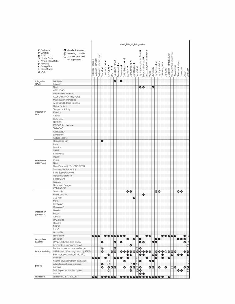
standard featuretweaking possibledata not providednot supported
BIM interoperability (gbXML, IFC)CAD interop. (fbx, dwg, sat, obj, IGES)
integrationgeneral
interoperability
pricing
validation
stand alone
CAAD/BIM integrated plugin(online/cloud/app) web based
3D plugin
live link - dynamic data exchange
�exible payment (subscription)bundled
payware
freewarefree for educational/non-comercialeducational/student discount
validated (CIE 171:2006)
integrationCAAD
integrationgeneral 3D
integrationBIM
AutoCADFreecad
Rhinoceros 3D
Architect3DEnvisioneerArchiTECH.PC
RevitARCHICADVectorworks ArchitectALLPLAN ARCHITECTUREMicrostation (Parasolid)
Digital ProjectTrelligence Af�nity
AECOsim Building Designer
Edi�ciusCaddie
BrisCADZWCAD Architecture
integrationCAD/CAM
CATIASolidworks
Inventor
InspireEvolve
Alias
CreoCreo Parametric/Pro/ENGINEERSiemens NX (Parasolid)Solid Edge (Parasolid)TopSolid (Parasolid)SpaceClaimIronCADGeomagic DesignKOMPAS-3DSketchUpFormIt 360/Pro3Ds maxMaya
BlenderCinema 4DLightwave
Poser
HoudiniDAZ StudioCarrara
MODOformZBonzai3D
DDS-CAD
TurboCAD
daylighting/lighting/solar
RadianceDAYSIM
EnergyPlusOpenStudioDOE
Nvidia OptixNvidia IRay/OptixPHANIE
A360
Oce
an
Rad
ianc
e -
clas
sic
Ligh
tCal
c
su2d
sLi
ghtS
tanz
aLi
ght S
tudi
oR
ayfro
nt
BIM
IQ
Ger
onim
o
AG
i32
Elu
mTo
ols
Ligh
tsol
veLi
ghtU
pAna
lytic
sD
IALu
x (4
, evo
)
ecoB
IM (T
AS
Eng
inee
ring)
LD A
ssis
tant
Sol
ar A
naly
sis
tool
Sha
dow
Ana
lysi
sC
hron
olux
DIA
L+S
uite
IDA
ICE
CS
TB D
1 P
HA
NIE
-201
0
Rad
ianc
e -
DAY
SIM
R
adia
nce
- ph
oton
map
Ligh
ting
Ana
lysi
s fo
r R
evit
Rel
uxS
uite
/ P
roA
ccel
erad
VE
LUX
Day
light
Vis
ualiz
er
Div
aD
AYS
IMpm
SP
OT
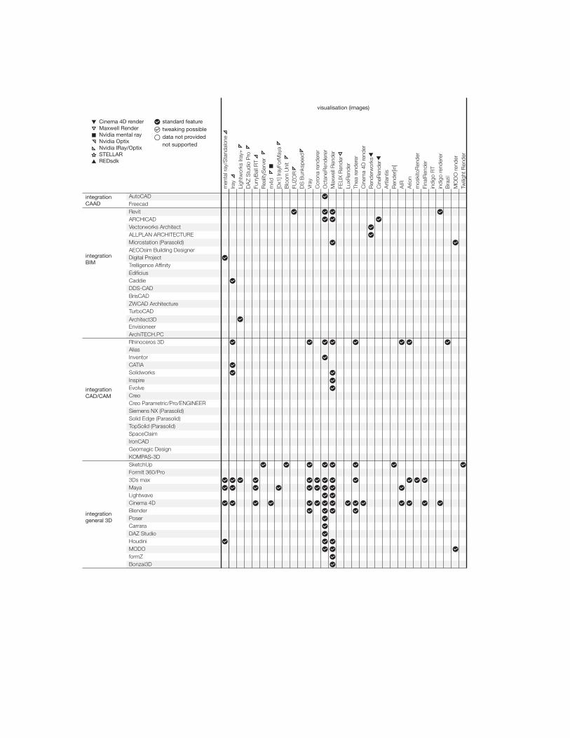
standard featuretweaking possibledata not providednot supported
Envisioneer
Trelligence Af�nity
AECOsim Building Designer
Edi�cius
integrationCAAD
integrationBIM
integrationCAD/CAM
SketchUpFormIt 360/Pro
AutoCADFreecad
DDS-CADBrisCADZWCAD ArchitectureTurboCAD
CATIASolidworks
Inventor
InspireEvolve
Alias
CreoCreo Parametric/Pro/ENGINEERSiemens NX (Parasolid)Solid Edge (Parasolid)TopSolid (Parasolid)SpaceClaimIronCADGeomagic DesignKOMPAS-3D
Rhinoceros 3D
Architect3D
ArchiTECH.PC
RevitARCHICADVectorworks ArchitectALLPLAN ARCHITECTUREMicrostation (Parasolid)
Digital Project
Caddie
integrationgeneral 3D
3Ds maxMaya
BlenderCinema 4DLightwave
Poser
HoudiniDAZ StudioCarrara
MODOformZBonzai3D
Art
lant
isR
ende
r[in]
Cor
ona
rend
erer
men
tal r
ay/S
tand
alon
eIra
yLi
ghtw
orks
Iray
+
Oct
aneR
ende
rer
Max
wel
l Ren
der
LuxR
ende
rTh
ea re
nder
erC
inem
a 4D
rend
erR
ende
rwor
ksC
ineR
ende
r
Ario
nm
oski
toR
ende
rFi
nalR
ende
r
indi
go re
nder
erB
razi
l
indi
go R
T
MO
DO
rend
erTw
ilight
Ren
der
Furr
yBal
l RT
FELI
X R
ende
r
DA
Z S
tudi
o P
ro
visualisation (images)
Rea
lityS
erve
r
FUZO
R
[0x1
] Ira
yFor
May
am
4d
Blo
om U
nit
Vray
AIR
DS
Bun
kspe
ed
Cinema 4D renderMaxwell Render
REDsdk
Nvidia OptixNvidia IRay/OptixSTELLAR
Nvidia mental ray
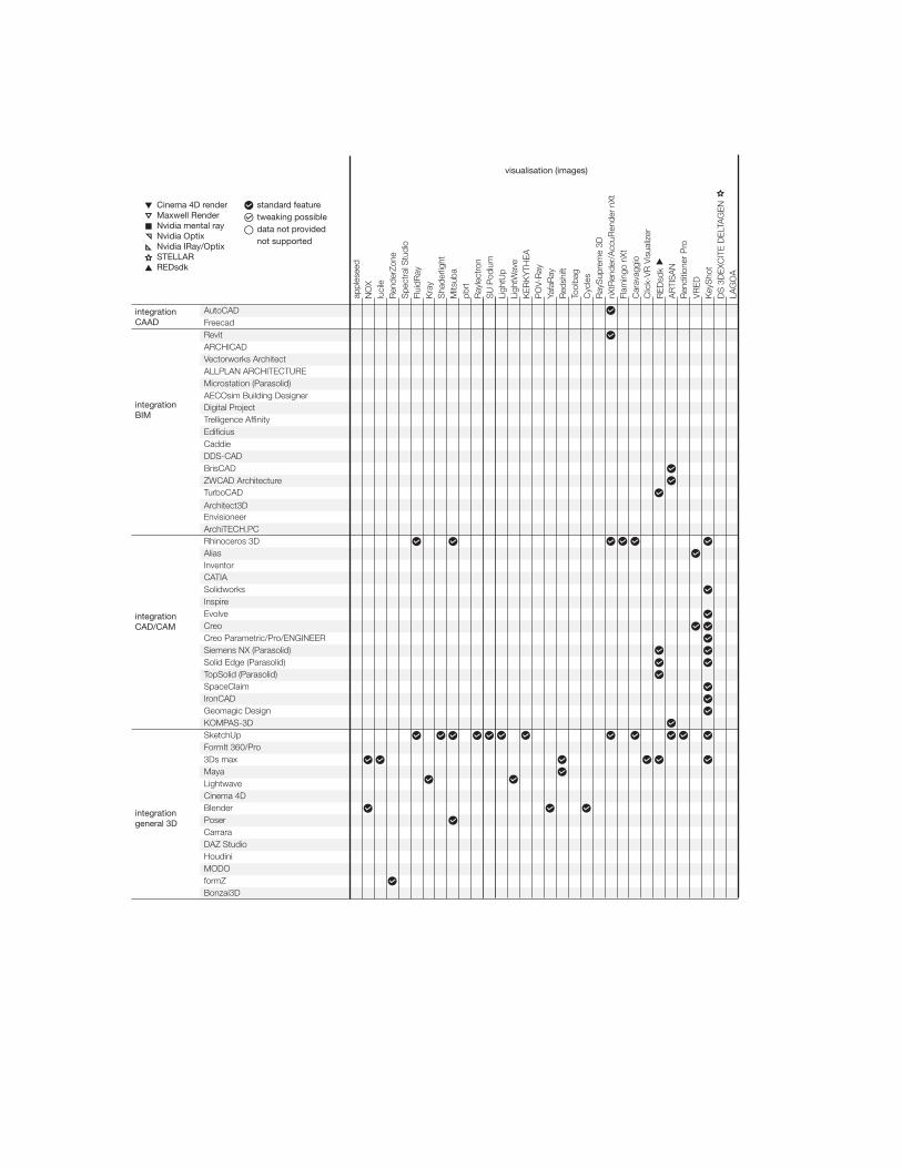
standard featuretweaking possibledata not providednot supported
Envisioneer
Trelligence Af�nity
AECOsim Building Designer
Edi�cius
integrationCAAD
integrationBIM
integrationCAD/CAM
SketchUpFormIt 360/Pro
AutoCADFreecad
DDS-CADBrisCADZWCAD ArchitectureTurboCAD
CATIASolidworks
Inventor
InspireEvolve
Alias
CreoCreo Parametric/Pro/ENGINEERSiemens NX (Parasolid)Solid Edge (Parasolid)TopSolid (Parasolid)SpaceClaimIronCADGeomagic DesignKOMPAS-3D
Rhinoceros 3D
Architect3D
ArchiTECH.PC
RevitARCHICADVectorworks ArchitectALLPLAN ARCHITECTUREMicrostation (Parasolid)
Digital Project
Caddie
integrationgeneral 3D
3Ds maxMaya
BlenderCinema 4DLightwave
Poser
HoudiniDAZ StudioCarrara
MODOformZBonzai3D
appl
esee
d
luci
leR
ende
rZon
eS
pect
ral S
tudi
oFl
uidR
ay
Sha
derli
ght
Mits
uba
visualisation (images)
NO
X
Kra
y
pbrt
Ray
lect
ron
SU
Pod
ium
nXtR
ende
r/A
ccuR
ende
r nX
t
VR
ED
Key
Sho
t
Flam
ingo
nXt
Ligh
tWav
e
LAG
OA
KE
RK
YTH
EA
Ligh
tUp
PO
V-R
ayYa
faR
ayR
edsh
ift
Cyc
les
DS
3D
EXC
ITE
DE
LTA
GE
N
Ray
Sup
rem
e 3D
Tool
bag
Car
avag
gio
Clic
k-V
R V
isua
lizer
RE
Dsd
kA
RTI
SA
NR
endi
tione
r P
ro
Cinema 4D renderMaxwell Render
REDsdk
Nvidia OptixNvidia IRay/OptixSTELLAR
Nvidia mental ray
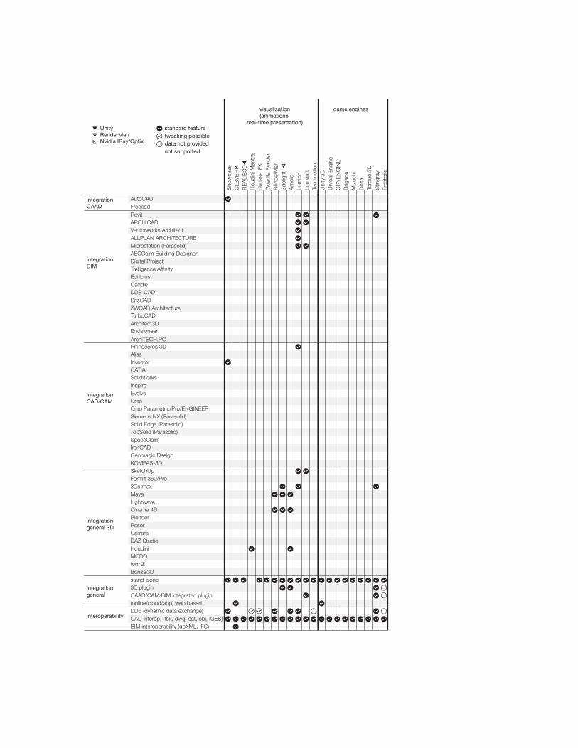
standard featuretweaking possibledata not providednot supported
Envisioneer
integrationgeneral
interoperability
stand alone
CAAD/CAM/BIM integrated plugin
BIM interoperability (gbXML, IFC)CAD interop. (fbx, dwg, sat, obj, IGES)
3D plugin
DDE (dynamic data exchange)(online/cloud/app) web based
Trelligence Af�nity
AECOsim Building Designer
Edi�cius
integrationCAAD
integrationBIM
integrationCAD/CAM
SketchUpFormIt 360/Pro
AutoCADFreecad
DDS-CADBrisCADZWCAD ArchitectureTurboCAD
CATIASolidworks
Inventor
InspireEvolve
Alias
CreoCreo Parametric/Pro/ENGINEERSiemens NX (Parasolid)Solid Edge (Parasolid)TopSolid (Parasolid)SpaceClaimIronCADGeomagic DesignKOMPAS-3D
Rhinoceros 3D
Architect3D
ArchiTECH.PC
RevitARCHICADVectorworks ArchitectALLPLAN ARCHITECTUREMicrostation (Parasolid)
Digital Project
Caddie
integrationgeneral 3D
3Ds maxMaya
BlenderCinema 4DLightwave
Poser
HoudiniDAZ StudioCarrara
MODOformZBonzai3D
visualisation(animations,
real-time presentation)
game engines
UnityRenderManNvidia IRay/Optix
Uni
ty 3
DU
nrea
l Eng
ine
Ren
derM
an
Torq
ue 3
DD
elta
Stin
gray
Fros
tbite
Arn
old
3del
ight
Lum
ion
Lum
enrt
CR
YE
NG
INE
Brig
ade
Twin
mot
ion
Miz
uchi
RE
ALI
S3D
Sho
wca
se
Hou
dini
Man
tra
clar
isse
iFX
Gue
rilla
Ren
der
CL3
VE
R
6. Conclusion
This review showed the most comprehensive review of the multidisciplinary solar design tools so far. Almost 200 tools were compared to about 70 features and their integration in around 50 3D, CAD/CAM and BIM software packages. For such an extensive review of around 21000 fields, tables were used to organize and present data in a straightforward way. Description part that preceded tables aimed to explain features that solar design tools use in order to analyze their capability for specific purposes. Since solar design tools has shown tendencies in spreading across multidisciplinary areas over the past years, this type of review was necessary in order to map innovative possibilities that can emerge. This paradigm shift should provide a framework for many areas to find common solutions to multi-performance concepts such as high-performance facades that can include many concepts such as kinetics, BIPV, CFS, DRS, phase-change materials in the same solution. Moreover, the review should broaden perspective of academics and practitioners from all included fields, all knowledge and experience levels to facilitate integration of their design processes. These two directions combined are expected to enable acceleration of innovative building and particularly façade solutions.
Appendix A. Appendix
A complete list of solar design tools, analyzed in this review, with information of their developers/software vendors and websites are presented in the following tables.

PVDeveloper/Company Product WebsiteNREL - US National Renewable Energy Laboratory System Advisor Model https://sam.nrel.govPVsyst SA PVsyst http://www.pvsyst.com/en/Valentin Software PV*SOL http://www.valentin-software.com/en/products/photovoltaics/57/pvsol-premiumSkelion Skelion http://www.skelion.com/index.htmACCA software S.p.A. Solarius-PV http://www.acca.it/software-impianti-fotovoltaici-gratisVela Solaris Polysun http://www.velasolaris.com/english/home.htmlSolar Energy Laboratory at the University of Wisconsin CECPV Calculator http://www.gosolarcalifornia.org/tools/nshpcalculator/download_calculator.phpNREL - US National Renewable Energy Laboratory PVwatts http://pvwatts.nrel.govNEMETSCHEK AG. DDS-CAD PV http://www.dds-cad.net/products/dds-cad-pv/INSEL INSEL http://www.insel.eu/index.php?id=301&L=1Solmetric PV Designer http://www.solmetric.comF-Chart Software PV F-CHART http://www.fchart.com/fchart/SMA Solar Technology AG SMA Off-Grid Con�gurator http://www.sma.de/en/products/planning-software/sma-off-grid-con�gurator.htmlLaplace System Co., Ltd. SolarPro http://www.lapsys.co.jp/english/products/pro.htmlTrace Software International Archelios Suite http://www.archelios.comMaui Solar Energy Software Corporation PV-DesignPro http://www.mauisolarsoftware.comNatural Resources Canada RETScreen Plus http://www.retscreen.net/ang/home.phpHOMER Energy LLC HOMER Pro http://www.homerenergy.com/index.htmlSolarschmiede PVscout http://www.solarschmiede.de/en/pvscout-20-premiumSTÖHR+SAUER CAD- und Computersystem GmbH HELIOS3D http://www.helios3d.com/index.php/en/downloads
OPTICAL DESIGNDeveloper/Company Product WebsiteLambda Research Corporation TracePro http://www.lambdares.comLTI Optics, LLC Photopia http://www.ltioptics.com/en/photopia-standalone-base.htmlZemax, LLC OpticStudio http://www.zemax.com/products/opticstudio/aboutBreault Research Organization, Inc. ASAP http://www.breault.com/software/about-asapPhoton Engineering FRED http://photonengr.com/software/OptiCAD Corp. OptiCAD http://www.opticad.comSynopsys' Optical Solutions Group LightTools http://optics.synopsys.com/lighttools/OPTIS SPEOS, THEIA RT http://www.optis-world.com/Product-offering/SPEOSIntegra Inc. Lumicept http://www.integra.jp/en/products/lumiceptBrandenburg GmbH LucidShape http://www.brandenburg-gmbh.de/products/lucidshape/product/lucidshape/Sinclair Optics, Inc. OSLO http://www.sinopt.comOptenso OpTaliX http://www.optenso.comCOMSOL Inc. COMSOL https://www.comsol.com/
DAYLIGHTING/WHOLE BUILDING ENERGY/URBANDeveloper/Company Product WebsiteEDSL TAS Engineering http://www.edsl.net/main/Software/Designer.aspxNREL, ANL, LBNL, ORNL, and PNNL OpenStudio https://www.openstudio.net/Sefaira SEFAIRA ARCHITECTURE http://sefaira.com/sefaira-architecture/DesignBuilder Software Ltd DesignBuilder http://www.designbuilder.co.uk/content/view/160/226/IES - Integrated Environmental Solutions Limited IES-VE https://www.iesve.comAutodesk Green Building Studio https://gbs.autodesk.com/GBS/Sbi - the Danish Building Research Institute BSim - SimLight, Xsun http://sbi.dk/en/bsim/about-bsimMostapha Sadeghipour Roudsari Honeybee http://www.food4rhino.com/project/ladybug-honeybee?etxMax C Doelling Mr. Comfy http://mrcomfy.orgLBNL - Lawrence Berkeley National Laboratory COMFEN https://windows.lbl.gov/software/comfen/comfen.htmlODS Engineering ODS Studio http://www.ods-engineering.com/tools/ods-studio/Vabi Software B.V. Vabi building performance http://www.vabisoftware.comBentley Systems AECOsim Building Designer http://www.bentley.com/en-US/Products/AECOsim+Building+Designer/GRAITEC ArchiWIZARD http://www.graitec.com/fr/archiwizard.aspTimur Dogan ARCHSIM http://archsim.comSustainable Design Lab at the MIT umi - urban daylighting http://urbanmodellinginterface.ning.com

DAYLIGHTING/LIGHTING/SOLARDeveloper/Company Product WebsiteLBNL - Lawrence Berkeley National Laboratory RADIANCE – classic http://www.radiance-online.orgChristoph Reinhart, Fraunhofer ISE, Harvard Uni., MIT, NRC RADIANCE – DAYSIM http://daysim.ning.comLBNL - Lawrence Berkeley National Laboratory RADIANCE – genBSDF http://radsite.lbl.gov/radiance/man_html/genBSDF.1.htmlRoland Schregle - Fraunhofer ISE, HSLU RADIANCE - photon map http://www.ise.fraunhofer.de/en/Harvard University, Solemma LLC Diva http://diva4rhino.comPenn State University DAYSIMpm http://daysim.ning.com/page/downloadEQUA Simulation AB IDA ICE http://www.equa.se/en/ida-iceDaylighting Innovations SPOT https://www.daylightinginnovations.com/spot-homeRelux Informatik AG ReluxSuite http://www.relux.bizNathaniel Jones and Christoph Reinhart, MIT Accelerad http://web.mit.edu/sustainabledesignlab/projects/Accelerad/J. Kaempf, C. Basurto, J.-L. Scartezzini - EPFL LESO Geronimo http://leso.ep�.ch/geronimoEstia SA DIAL+Suite http://www.dialplus.ch/#!home/c16ndJosh Kjenner, Thomas Bleicher su2ds https://code.google.com/p/su2ds/Die Lichtplaner Light Studio http://www.lightstudio.at/default_e.aspLight Foundry, LLC LightStanza http://lightstanza.comAutodesk Lighting Analysis for Revit http://www.autodesk.com/products/lighting-analysis-revit/overviewAutodesk Solar Analysis tool https://beta.autodesk.com/callout/?callid=A85F5FB11247411E985ED97605743273VELUX, LUXION VELUX Daylight Visualizer http://viz.velux.com/daylight_visualizer/aboutLighting Analysts AGi32 http://www.agi32.com/index.php?id=11Lighting Analysts ElumTools http://www.elumtools.com/index.php?id=1EPFL LIPID Lightsolve http://lightsolve.ep�.chLightUp Analytics Ltd. LightUpAnalytics http://www.lightup-analytics.comDIAL GmbH DIALux http://www.dial.de/DIAL/en/dialux/about.htmlEnviro-Systems LightCalc http://www.lightcalc.comCSTB PHANIE http://www.cstb.fr/dae/en/nos-produits-et-formations/outils-de-calcul/phanie.htmlCadline ecoBIM http://www.cadline.co.uk/Products/BIM/Products/ecoBIMDesign & Drafting LD Assistant http://www.ldassistant.comArchiWIZARD ArchiWIZARD V3 Plug-in https://extensions.sketchup.com/en/content/plug-archiwizardDeltaCodes Sp. z o.o Shadow Analysis http://www.deltacodes.pl/enLinks' System Software Chronolux https://sites.google.com/site/lssoft2011/home/chronoluxEclat-Digital Recherche Ocean http://www.eclat-digital.comOldcastle BuildingEnvelope, NVIDIA BIM IQ http://www.bimiq.com
VISUALISATION (animations)Developer/Company Product WebsiteAutodesk Autodesk Showcase http://www.autodesk.com/products/showcase/overviewCL3VER, NVIDIA CL3VER https://www.cl3ver.comREAL VISUAL GROUP LTD REALIS3D http://realis3d.com/#introSide Effects Software Inc. Houdini Mantra http://www.sidefx.com/index.php?option=com_content&task=view&id=1001Isotropix SAS. clarisse iFX http://www.isotropix.com/index.php?to=products&productid=1&view=sub-overview-renderingMercenaries Engineering Guerilla Render http://guerillarender.comPixar RenderMan https://renderman.pixar.com/view/rendermanDNA Research 3delight http://www.3delight.com/en/index.phpSolid Angle S.L. Arnold https://www.solidangle.comAct-3D B.V. Lumion/PRO http://lumion3d.come-on software, inc. Lumenrt http://www.lumenrt.comAbvent Group Twinmotion http://vador.abvent.com/twinmotion/?lang=en
GAME ENGINESDeveloper/Company Product WebsiteUnity Technologies Unity 3D https://unity3d.comEPIC GAMES, INC. Unreal Engine https://www.unrealengine.com/previous-versionsCrytek CRYENGINE http://www.crytek.com/cryengineOTOY Brigade https://brigade.otoy.comSilicon Studio Corp. Mizuchi http://www.siliconstudio.co.jp/middleware/mizuchi/en/Delta Engine GmbH Delta Engine http://deltaengine.netGarageGames Torque 3D http://www.garagegames.com/products/torque-3dAutodesk Stingray http://www.autodesk.com/products/stingray/overviewFrostbite Frostbite http://www.frostbite.com

VISUALISATION (images)Developer/Company Product WebsiteAutodesk, NVIDIA mental ray/Standalone http://www.nvidia-arc.com/mentalray.html / http://www.autodesk.com/products/mental-ray-standalone/overviewAutodesk, NVIDIA Iray http://www.nvidia-arc.com/iray.html / Lightworks, NVIDIA Lightworks Iray+ http://www.lightworks-iray.comDAZ Productions, Inc., NVIDIA DAZ Studio Pro http://www.daz3d.com/daz_studioArt And Animation studio, NVIDIA FurryBall RT http://furryball.aaa-studio.eumigenius, NVIDIA RealityServer http://www.migenius.comat² GmbH m4d http://www.m4d.info/index.php[0x1] Software und Consluting GmbH [0x1] IrayForMaya http://www.0x1-software.com/en/produkte/0x1-irayformaya.htmlmigenius, NVIDIA Bloom Unit https://www.bloomunit.com/en/Kalloc Studios FUZOR https://www.kalloctech.comChaos Group Vray http://www.chaosgroup.com/en/2/index.htmlRender Legion s.r.o. Corona renderer https://corona-renderer.comOTOY Inc OctaneRenderer https://home.otoy.com/render/octane-render/Next Limit Maxwell Render http://www.maxwellrender.com/Legal Stack! Studios FELIX Render http://www.felixrender.comLuxRender LuxRender http://www.luxrender.net/en_GB/indexSolid Iris Technologies Thea renderer https://www.thearender.com/site/MAXON Computer GmbH Cinema 4D render http://www.maxon.net/products/cinema-4d-visualize/rendering.htmlNemetschek Vectorworks, Inc. Vectorworks Renderworks http://www.vectorworks.net/renderworks/Graphisoft, MAXON Computer GmbH CineRender http://www.maxon.net/pt/news/singleview-default/article/maxon-cinerender-integration-adds-high-end-render-quality-to-archicadR-18.htmlAbvent Group Artlantis http://artlantis.com/en/homeAbvent Group Render[in] http://renderin.comSiTex Graphics AIR http://www.sitexgraphics.com/html/air.htmlRandomControl Arion http://www.randomcontrol.com/#1cebas Visual Technology Inc. moskitoRender http://www.cebas.com/?pid=productinfo&prd_id=175cebas Visual Technology Inc. FinalRender http://www.cebas.com/?pid=productinfo&prd_id=137Glare Technologies Limited. indigo RT http://www.indigorenderer.com/indigo_rtGlare Technologies Limited. indigo renderer/for Revit http://www.indigorenderer.com/indigo3Robert McNeel & Associates Brazil http://brazil.rhino3d.comTHE FOUNDRY MODO render https://www.thefoundry.co.uk/products/modo/features/#RenderingTwilight Render LLC Twilight Render http://twilightrender.comFRANÇOIS BEAUNE et al. appleseed http://appleseedhq.netEvermotion NOX http://www.evermotion.org/noxFixstars Corporation lucile http://www.�xstars.com/en/lucille/AutoDesSys, Inc. RenderZone http://www.formz.com/products/renderzone.htmlSpectral Pixel Spectral Studio http://www.spectralpixel.com/products/ss_home.htmlFluid Interactive Inc. FluidRay http://www.�uidray.comMindBerries Kray http://www.kraytracing.comArtVPS Ltd. Shaderlight https://www.artvps.comWenzel Jakob Mitsuba https://www.mitsuba-renderer.orgMatt Pharr, Greg Humphreys pbrt https://github.com/mmp/pbrt-v2SoftByte Labs Inc. Raylectron http://raylectron.com/webver2/Cadalog, Inc. SU Podium http://www.suplugins.com/LightUp Ltd LightUp https://www.light-up.co.uk/NewTek Inc. LightWave https://www.lightwave3d.comSolid Iris Technologies KERKYTHEA http://www.kerkythea.net/cms/Persistence of Vision Raytracer Pty. Ltd. POV-Ray http://www.povray.orgAlejandro Conty Estévez et al. YafaRay http://www.yafaray.orgRedshift Rendering Technologies, Inc. Redshift https://www.redshift3d.comMarmoset LLC Toolbag https://www.marmoset.co/toolbagBlender Foundation Cycles https://www.blender.org/features/BrainDistrict GmbH. RaySupreme 3D http://www.braindistrict.com/en/raysupreme-3dRender Plus Software nXtRender/AccuRender nXt http://www.renderplus.com/wp2/Scott Davidson Flamingo nXt http://nxt.�amingo3d.com/page/product-overviewCaravaggio Caravaggio RENDER http://www.caravaggio3d.com/products/renderCodeblend Click-VR Visualizer http://www.codeblend.com/products/visualizer/REDWAY3D S.A.S. REDsdk http://www.redway3d.com/products/redsdk/Pictorex Ltd ARTISAN http://www.pictorex.com/index.phpIMSI/Design, LLC. Renditioner Pro http://www.imsidesign.com/Products/RenditionerAutodesk VRED http://www.autodesk.com/products/vred/overviewLUXION KeyShot https://www.keyshot.comDassault Systèmes DS Bunkspeed Shot, Pro http://www.bunkspeed.com/#s=2Dassault Systemes 3DExcite GmbH DS 3DEXCITE DELTAGEN https://www.rtt.ag/enLAGOA LAGOA http://home.lagoa.com

CAADDeveloper/Company Product WebsiteAutodesk AutoCAD http://www.autodesk.com/products/autocad/overview
Freecad http://www.freecadweb.org
BIMDeveloper/Company Product WebsiteAutodesk Revit http://www.autodesk.com/products/revit-family/overviewGraphisoft ArchiCAD http://www.graphisoft.com/archicad/Nemetschek Vectorworks, Inc. Vectorworks Architect http://www.vectorworks.net/architect/Allplan Deutschland GmbH ALLPLAN ARCHITECTURE http://www.allplan.com/en/software/architecture/allplan-architecture-2016.htmlBentley Systems, Incorporated Microstation (Parasolid) http://www.bentley.com/en-US/Products/MicroStation/Bentley Systems, Incorporated AECOsim Building Designer http://www.bentley.com/en-US/Products/AECOsim+Building+Designer/Digital Project, Inc. Digital Project http://www.digitalproject3d.comTrelligence, Inc. Trelligence Af�nity http://www.trelligence.com/af�nity_overview.phpACCA software S.p.A. Edi�cius http://www.accasoftware.com/en/id4/bim.htmlCaddie Software Caddie http://www.caddiesoftware.com/index.phpData Design System DDS-CAD http://www.dds-cad.netBricsys BrisCAD https://www.bricsys.com/en_INTL/bricscad/ZWCAD Software Co. ZWCAD Architecture http://www.zwsoft.com/zwcad/zwcad_architecture/IMSI/Design, LLC. TurboCAD http://www.turbocad.com/TurboCAD/TurboCAD-Windows/TurboPDF-and-TurboCAD-Deluxe-Bundle#10632331-overviewCadsoft Corporation Envisioneer http://www.cadsoft.com/products/Onuma, Inc. Onuma http://www.onuma.comAvanquest Software Architect3D http://www.myarchitect3d.com/EDICAD ArchiTECH.PC http://www.edicad.com/Produit_APC.aspx
CAD/CAMDeveloper/Company Product WebsiteRobert McNeel & Associates Rhinoceros 3D https://www.rhino3d.comAutodesk Alias http://www.autodesk.com/products/alias-products/overviewAutodesk Inventor http://www.autodesk.com/products/inventor/overviewDassault Systèmes CATIA http://www.3ds.com/products-services/catiaDassault Systèmes Solidworks http://www.solidworks.comsolidThinking, Inc. Inspire http://www.solidthinking.com/ProductExperience.aspx?item=Inspire%20Experience&category=ProductssolidThinking, Inc. Evolve http://www.solidthinking.com/ProductOverview.aspx?item=Evolve%20Overview&category=ProductsPTC Inc. PTC Creo http://www.ptc.com/product/creoPTC Inc. Creo Parametric/Pro/ENGINEER http://www.ptc.com/cad/3d-cad/creo-parametricSiemens Product Lifecycle Management Software Inc. Siemens NX (Parasolid) http://www.plm.automation.siemens.com/en_us/products/nx/Siemens Product Lifecycle Management Software Inc. Solid Edge (Parasolid) http://www.plm.automation.siemens.com/en_us/products/solid-edge/Missler Software TopSolid (Parasolid) http://www.topsolid.comSpaceClaim Corporation. SpaceClaim http://www.spaceclaim.com/en/default.aspxIronCAD, LLC. IronCAD http://www.ironcad.comGeomagic Geomagic Design http://www.geomagic.com/en/products/design/overviewASCON KOMPAS-3D http://ascon.net/solutions/kompas_3d/
general 3DDeveloper/Company Product WebsiteTrimble Navigation Limited SketchUp http://www.sketchup.comAutodesk FormIT 360 http://www.autodesk.com/products/formit-360/overviewAutodesk 3Ds max http://www.autodesk.com/products/3ds-max/overviewAutodesk Maya http://www.autodesk.com/products/maya/overviewNewTek Inc. Lightwave https://www.lightwave3d.comMAXON Computer Cinema 4D http://www.maxon.net/?id=1499Blender.org Blender https://www.blender.orgSmith Micro Software, Inc. Poser http://my.smithmicro.com/poser-3d-animation-software.htmlDAZ Productions, Inc. Carrara http://www.daz3d.com/carrara-8-5-proDAZ Productions, Inc. DAZ Studio http://www.daz3d.com/daz_studioSide Effects Software Inc. Houdini http://www.sidefx.comThe Foundry Visionmongers Ltd MODO https://www.thefoundry.co.uk/products/modo/AutoDesSys, Inc. formZ http://www.formz.comAutoDesSys, Inc. Bonzai3D

References
[1] W. L. Carroll, “Daylighting simulation: methods, algorithms, and resources,” Lawrence Berkeley Natl. Lab., 1999.
[2] C. F. Reinhart and S. Herkel, “The simulation of annual daylight illuminance distributions — a state-of-the-art comparison of six RADIANCE-based methods,” Energy Build., vol. 32, no. 2, pp. 167–187, Jul. 2000.
[3] C. Reinhart and A. Fitz, “Findings from a survey on the current use of daylight simulations in building design,” Energy Build., vol. 38, no. 7, pp. 824–835, Jul. 2006.
[4] Z. Rogers, “Overview of daylight simulation tools,” presented at the VELUX 2nd Daylight Symposium, London, UK, 2007, vol. 7, p. 2007.
[5] A. D. Galasiu and C. F. Reinhart, “Current daylighting design practice: a survey,” Build. Res. Inf., vol. 36, no. 2, pp. 159–174, 2008.
[6] S. Kota and J. S. Haberl, “Historical Survey of daylighting calculations methods and their use in energy performance simulations,” in Proceedings of the Ninth International Conference for Enhanced Building Operations, Austin, Texas, USA, 2009.
[7] C. E. Ochoa, M. B. Aries, and J. L. Hensen, “State of the art in lighting simulation for building science: a literature review,” J. Build. Perform. Simul., vol. 5, pp. 209–233, 2012.
[8] A. Iversen et al., SBI 2013:26 - Daylight calculations in practice: An investigation of the ability of nine daylight simulation programs to calculate the daylight factor in five typical rooms. København: Statens Byggeforskningsinstitut, 2013.
[9] A. Schlueter and F. Thesseling, “Building information model based energy/exergy performance assessment in early design stages,” Autom. Constr., vol. 18, no. 2, pp. 153–163, Mar. 2009.
[10] S. Attia, L. Beltrán, A. De Herde, and J. Hensen, “‘Architect Friendly’: A Comparison of Ten Different Building Performance Simulation Tools,” in Proceedings of the Building Simulation 2009 Conference, Glasgow, Scotland, 2009, pp. 201–211.
[11] L. Weytjens, S. Attia, G. Verbeeck, and A. De Herde, “A comparative study of the ‘architect-friendliness’ of six building performance simulation tools,” in Proceedings SB10 Euregion: Towards 0-impact buildings and environments, Maastricht, Liège and Aachen, 2010.
[12] X. Shi and W. Yang, “Performance-driven architectural design and optimization technique from a perspective of architects,” Autom. Constr., vol. 32, pp. 125–135, Jul. 2013.
[13] J. M. L. (Jaime M. L. Gagne, “An interactive performance-based expert system for daylighting in architectural design,” PhD Thesis, Massachusetts Institute of Technology, Boston, MA, USA, 2011.
[14] J. Freeman, J. Whitmore, N. Blair, and A. P. Dobos, “Validation of multiple tools for flat plate photovoltaic modeling against measured data,” National Renewable Energy Laboratory (NREL), Denver West Parkway Golden, CO, USA, NREL/TP-6A20-61497 Prepared under Task No. SS13.5010, 2014.
[15] P. J. Axaopoulos, E. D. Fylladitakis, and K. Gkarakis, “Accuracy analysis of software for the estimation and planning of photovoltaic installations,” Int. J. Energy Environ. Eng., vol. 5, no. 1, pp. 1–7, Jan. 2014.
[16] S. Freitas, C. Catita, P. Redweik, and M. C. Brito, “Modelling solar potential in the urban environment: State-of-the-art review,” Renew. Sustain. Energy Rev., vol. 41, pp. 915–931, Jan. 2015.
[17] M. C. Dubois and M. Horvat, “State-of-the-Art of Digital Tools Used by Architects for Solar Design,” International Energy Agency for Solar Heating and Cooling, Paris, France, T. 41. B. 1, 2010.
[18] “Task 41: Solar Energy and Architecture -Solar design of buildings for architects: Review of solar design tools.” The International Energy Agency Solar Heating and Cooling Programme (IEA SHC), Jul-2012.
[19] J. Kanters, M. Horvat, and M.-C. Dubois, “Tools and methods used by architects for solar design,” Energy Build., vol. 68, pp. 721–731, 2014.
[20] D. B. Crawley, J. W. Hand, M. Kummert, and B. T. Griffith, “Contrasting the capabilities of building energy performance simulation programs,” Build. Environ., vol. 43, no. 4, pp. 661–673, Apr. 2008.
[21] J. Pineda, “A Parallel Algorithm for Polygon Rasterization,” in Proceedings of the 15th Annual Conference on Computer Graphics and Interactive Techniques, New York, NY, USA, 1988, pp. 17–20.
[22] R. L. Cook, L. Carpenter, and E. Catmull, “The Reyes image rendering architecture,” in ACM SIGGRAPH Computer Graphics, 1987, vol. 21, pp. 95–102.
[23] M. F. Modest, Radiative Heat Transfer. Waltham, MA, USA: Academic Press, 2013.
[24] M. Cohen et al., Radiosity and Realistic Image Synthesis. Morgan Kaufmann, 1993.
[25] A. Watt, 3D Computer Graphics, 2nd ed. Boston, MA, USA: Addison-Wesley Longman Publishing Co., Inc., 1993.
[26] D. S. Immel, M. F. Cohen, and D. P. Greenberg, “A Radiosity Method for Non-diffuse Environments,” in Proceedings of the 13th Annual Conference on Computer Graphics and Interactive Techniques, New York, NY, USA, 1986, pp. 133–142.
[27] P. Hanrahan, D. Salzman, and L. Aupperle, “A Rapid Hierarchical Radiosity Algorithm,” in Proceedings of the 18th Annual Conference on Computer Graphics and Interactive Techniques, New York, NY, USA, 1991, pp. 197–206.
[28] P. Bekaert, “Hierarchical and stochastic algorithms for radiosity,” PhD Thesis, The Katholieke Universiteit Leuven, Leuven, Belgium, 1999.
[29] A. Keller, “Instant Radiosity,” in Proceedings of the SIGGRAPH ’97, 1997, pp. 49–56.

[30] T. Whitted and J. D. Foley, “An Improved Illumination Model for Shaded Display,” 1980.
[31] J. T. Kajiya, “The rendering equation,” in ACM Siggraph Computer Graphics, Dallas, USA, 1986, vol. 20, pp. 143–150.
[32] P. S. Shirley, “Physically Based Lighting Calculations for Computer Graphics,” PhD Thesis, University of Illinois at Urbana-Champaign, Urbana, Illinois, USA, 1991.
[33] M. Pharr and G. Humphreys, Physically Based Rendering: From Theory to Implementation. Burlington, MA, USA: Morgan Kaufmann, 2010.
[34] H. Pacheco, “Ray Tracing in Industry. An up-to-date review of industrial ray tracing applications and academic contributions.” .
[35] G. S. Fishman, Monte Carlo: concepts, algorithms, and applications. New York, NY, USA: Springer, 1997.
[36] P. Shirley, C. Wang, and K. Zimmerman, “Monte Carlo Techniques for Direct Lighting Calculations,” ACM Trans Graph, vol. 15, no. 1, pp. 1–36, Jan. 1996.
[37] M. H. Kalos and P. A. Whitlock, Monte Carlo Methods. Vol. 1: Basics. New York, NY, USA: Wiley-Interscience, 1986.
[38] R. L. Cook, T. Porter, and L. Carpenter, “Distributed Ray Tracing,” in Proceedings of the 11th Annual Conference on Computer Graphics and Interactive Techniques, New York, NY, USA, 1984, pp. 137–145.
[39] E. Veach and L. J. Guibas, “Optimally Combining Sampling Techniques for Monte Carlo Rendering,” in Proceedings of the 22Nd Annual Conference on Computer Graphics and Interactive Techniques, New York, NY, USA, 1995, pp. 419–428.
[40] P. Clarberg, W. Jarosz, T. Akenine-Möller, and H. W. Jensen, “Wavelet Importance Sampling: Efficiently Evaluating Products of Complex Functions,” in ACM SIGGRAPH 2005 Papers, New York, NY, USA, 2005, pp. 1166–1175.
[41] D. Burke, A. Ghosh, and W. Heidrich, “Bidirectional Importance Sampling for Direct Illumination.,” Render. Tech., vol. 5, pp. 147–156, 2005.
[42] G. J. Ward and F. M. Rubinstein, “A New Technique for Computer Simulation of Illuminated Spaces,” J. Illum. Eng. Soc., vol. 17, no. 1, pp. 80–91, Jan. 1988.
[43] G. W. Larson, R. Shakespeare, C. Ehrlich, J. Mardaljevic, E. Phillips, and P. Apian-Bennewitz, Rendering with radiance: the art and science of lighting visualization. Morgan Kaufmann San Francisco, CA, 1998.
[44] E. Lafortune, “Mathematical models and Monte Carlo algorithms for physically based rendering,” PhD Thesis, Katholieke Universiteit Leuven, Leuven, Belgium, 1996.
[45] E. P. Lafortune and Y. D. Willems, “Bi-Directional Path Tracing,” in Proceedings of Third International Conference on Computational Graphics and Visualization Techniques, Alvor, Algarve, Portugal, 1993, pp. 145–153.
[46] H. W. Jensen, “Global Illumination using Photon Maps,” in Rendering Techniques’ 96, Vienna, Austria, 1996, pp. 21–30.
[47] H. W. Jensen and N. J. Christensen, “Photon Maps in Bidirectional Monte Carlo Ray Tracing of Complex Objects.” Technical University of Denmark, 1994.
[48] R. Schregle, L. Grobe, and S. Wittkopf, “Progressive photon mapping for daylight redirecting components,” Sol. Energy, vol. 114, pp. 327–336, Apr. 2015.
[49] E. Veach, “Robust Monte Carlo methods for light transport simulation,” PhD Thesis, Stanford University, Stanford, CA, USA, 1997.
[50] E. Veach and L. J. Guibas, “Metropolis Light Transport,” in Proceedings of the 24th Annual Conference on Computer Graphics and Interactive Techniques, New York, NY, USA, 1997, pp. 65–76.
[51] Manzi, Marco, Kettunen, Markus, Aittala, Miika, Lehtinen, Jaakko, Durand, Frédo, and Zwicker, Matthias, “Gradient-Domain Bidirectional Path Tracing,” ACM Trans. Graph. TOG, vol. 34, no. 4, p. 123, 2015.
[52] D. Cline, J. Talbot, and P. Egbert, “Energy Redistribution Path Tracing,” in ACM SIGGRAPH 2005 Papers, New York, NY, USA, 2005, pp. 1186–1195.
[53] J. Lehtinen, T. Karras, S. Laine, M. Aittala, F. Durand, and T. Aila, “Gradient-domain Metropolis Light Transport,” ACM Trans Graph, vol. 32, no. 4, p. 95:1–95:12, Jul. 2013.
[54] C. Kelemen, L. Szirmay-Kalos, G. Antal, and F. Csonka, “A Simple and Robust Mutation Strategy for the Metropolis Light Transport Algorithm,” EUROGRAPHICS 2002 Comput. Graph. Forum, vol. 21, no. 3, pp. 531–540, Sep. 2002.
[55] W. Jakob and S. Marschner, “Manifold Exploration: a Markov Chain Monte Carlo technique for rendering scenes with difficult specular transport,” ACM Trans. Graph. TOG, vol. 31, no. 4, p. 58, 2012.
[56] W. Jakob, “Mitsuba renderer,” Httpwww Mitsuba-Render. Org, 2010.
[57] B. Walter, A. Arbree, K. Bala, and D. P. Greenberg, “Multidimensional Lightcuts,” in ACM SIGGRAPH 2006 Papers, New York, NY, USA, 2006, pp. 1081–1088.
[58] B. Walter, S. Fernandez, A. Arbree, K. Bala, M. Donikian, and D. P. Greenberg, “Lightcuts: A Scalable Approach to Illumination,” in ACM SIGGRAPH 2005 Papers, New York, NY, USA, 2005, pp. 1098–1107.
[59] J. P. G. Cabeleira, “Combining rasterization and ray tracing techniques to approximate global illumination in real-time,” Master Thesis, Instituto Superior Técnico, Lisbon, Portugal, 2010.
[60] W. Hu, Y. Huang, F. Zhang, G. Yuan, and W. Li, “Ray tracing via GPU rasterization,” Vis. Comput., vol. 30, no. 6–8, pp. 697–706, May 2014.
[61] S. Lagarde and C. de Rousiers, “Moving Frostbite to Physically Based Rendering,” presented at the SIGGRAPH 2014 Conference, Vancouver, 2014.
[62] R. Schregle, “Daylight simulation with photon maps,” PhD Thesis, Saarland University, Saarbrücken, Germany, 2007.

[63] F. Frontini, “Daylight and solar control in buildings. General evaluation and optimization of a new angle selective glazing façade,” PhD Thesis, Politecnico di Milano, Milan, Italy, 2011.
[64] N. Jakica and A. Zanelli, “Dynamic Visualization of Optical and Energy Yield Co-Simulation of New Generation BIPV Envelope in Early Design Phase Using Sustom Ray Tracing Algorithm in Phyton,” in Proceedings of Advanced Building Skins Conference, Bressanone, Italy, 2014, pp. 1031–1038.
[65] K. Crane, Bias in rendering. 2006.
[66] G. J. Ward, F. M. Rubinstein, and R. D. Clear, “A Ray Tracing Solution for Diffuse Interreflection,” in Proceedings of the 15th Annual Conference on Computer Graphics and Interactive Techniques, New York, NY, USA, 1988, pp. 85–92.
[67] CIE, “171:2006. Test Cases to Assess the Accuracy of Lighting Computer Programs.” CIE Central Bureau, Vienna, Austria, 2006.
[68] F. Maamari, M. Fontoynont, and N. Adra, “Application of the CIE test cases to assess the accuracy of lighting computer programs,” Energy Build., vol. 38, no. 7, pp. 869–877, Jul. 2006.
[69] R. Schregle and J. Wienold, “Physical validation of global illumination methods: measurement and error analysis,” in Computer Graphics Forum, 2004, vol. 23, pp. 761–781.
[70] C. Reinhart, “Daylight performance predictions,” in Building performance simulation for design and operation, Abingdon, Oxon; New York, NY: Spon Press, 2011, pp. 235–277.
[71] C. Reinhart and P.-F. Breton, “Experimental Validation of Autodesk® 3ds Max® Design 2009 and Daysim 3.0,” LEUKOS, vol. 6, no. 1, pp. 7–35, Jul. 2009.
[72] Y. Khalidi, “Building a Cloud Computing Platform for New Possibilities,” Computer, vol. 44, no. 3, pp. 29–34, 2011.
[73] T. J. Purcell, I. Buck, W. R. Mark, and P. Hanrahan, “Ray Tracing on Programmable Graphics Hardware,” in Proceedings of the 29th Annual Conference on Computer Graphics and Interactive Techniques, New York, NY, USA, 2002, pp. 703–712.
[74] M. Christen, “Ray tracing on GPU,” Diploma thesis, University of Applied Sciences Basel (FHBB), Basel, Switzerland, 2005.
[75] D. Robertson, K. Campbell, S. Lau, and T. Ligocki, “Parallelization of Radiance For Real Time Interactive Lighting Visualization Walkthroughs,” in Supercomputing, ACM/IEEE 1999 Conference, 1999, pp. 61–61.
[76] Chaos Group Labs, “Guide to GPU V.1.” Chaos Group Labs, 2016.
[77] D. G. Van Antwerpen, “Unbiased physically based rendering on the GPU,” Master Thesis, Delft University of Technology, Delft, the Netherlands, 2011.
[78] E. Naboni, Y. Zhang, A. Maccarini, E. Hirsch, and D. Lezzi, “Extending the use of parametric simulation in practice through a cloud based online service,” in Proceedings of 1st IBPSA-Italy Building Simulation Applications Conference, Bozen/Bolzano, Italy, 2013, vol. 30, pp. 105–112.
[79] S. Parker, W. Martin, P. J. Sloan, P. Shirley, B. Smits, and C. Hansen, “Interactive ray tracing,” in Proceedings of the 1999 symposium on Interactive 3D graphics, Atlanta, GA, USA, 1999, pp. 119–126.
[80] I. Wald and P. Slusallek, “State of the art in interactive ray tracing,” in State of the Art Reports of the EUROGRAPHICS 2001, Manchester, UK, 2001, vol. 2001, pp. 21–42.
[81] J. Novák, V. Havran, and C. Dachsbacher, “Path regeneration for interactive path tracing,” in Proceedings of the EUROGRAPHICS - Short Papers, Norköping, Sweden, 2010.
[82] I. C. Doidge, M. W. Jones, and B. Mora, “Mixing Monte Carlo and progressive rendering for improved global illumination,” Vis. Comput., vol. 28, no. 6–8, pp. 603–612, Apr. 2012.
[83] C. F. Borges, “Trichromatic approximation method for surface illumination,” J. Opt. Soc. Am., vol. 8, no. 8, p. 1319, Aug. 1991.
[84] G. Evans and M. D. McCool, “Stratified wavelength clusters for efficient spectral monte carlo rendering,” in Proceedings of the Conference on Graphics interface ’99, Kingston, Ontario, 1999, vol. 99, pp. 42–49.
[85] A. I. Ruppertsberg and M. Bloj, “Rendering complex scenes for psychophysics using RADIANCE: How accurate can you get?,” JOSA A, vol. 23, no. 4, pp. 759–768, Apr. 2006.
[86] A. S. Glassner, Principles of Digital Image Synthesis. San Francisco, CA, USA: Morgan Kaufmann, 1995.
[87] M. Raab, D. Seibert, and A. Keller, “Unbiased global illumination with participating media,” in Monte Carlo and Quasi-Monte Carlo Methods 2006, Springer, 2008, pp. 591–605.
[88] W. Jarosz, D. Nowrouzezahrai, R. Thomas, P.-P. Sloan, and M. Zwicker, “Progressive Photon Beams,” in Proceedings of the 2011 SIGGRAPH Asia Conference, New York, NY, USA, 2011, p. 181:1–181:12.
[89] J. Mardaljevic, “How to Maintain Neutral Daylight Illumination with SageGlass® Electrochromic Glazing,” Loughborough University, Loughborough, UK, 2015.
[90] B. Tandianus, H. Johan, H. S. Seah, and F. Lin, “Spectral caustic rendering of a homogeneous caustic object based on wavelength clustering and eye sensitivity,” Vis. Comput., pp. 1–14, Oct. 2014.
[91] S. W. Thomas, “Dispersive refraction in ray tracing,” Vis. Comput., vol. 2, no. 1, pp. 3–8, Jan. 1986.
[92] LightWorks, “LightWorks iRay - Architectural Toolkit Overview,” 2015.
[93] P. M. Deville, S. Merzouk, D. Cazier, and J. C. Paul, “Spectral Data Modeling for a Lighting Application,” Comput. Graph. Forum, vol. 13, no. 3, pp. 97–106, Aug. 1994.
[94] G. M. Johnson and M. D. Fairchild, “Full-Spectral Color Calculations in Realistic Image Synthesis,” IEEE Comput. Graph. Appl., vol. 19, no. 4, pp. 47–53, 1999.

[95] M. S. Peercy, “Linear color representations for full speed spectral rendering,” in Proceedings of the 20th annual conference on Computer graphics and interactive techniques, Anaheim, CA, USA, 1993, pp. 191–198.
[96] G. Ward and E. Eydelberg-Vileshin, “Picture Perfect RGB Rendering Using Spectral Prefiltering and Sharp Color Primaries.,” in A Report on the 13th Eurographics Workshop on Rendering, Pisa, Italy, 2002, pp. 117–124.
[97] M. Andersen, A. Guillemin, M. L. Ámundadóttir, and S. F. Rockcastle, “Beyond illumination: An interactive simulation framework for non-visual and perceptual aspects of daylighting performance,” 2013.
[98] K. Konis, “A novel circadian daylight metric for building design and evaluation,” Build. Environ., vol. 113, pp. 22–38, Feb. 2017.
[99] M. Andersen, J. Mardaljevic, and S. Lockley, “A framework for predicting the non-visual effects of daylight – Part I: photobiology- based model,” Light. Res. Technol., vol. 44, no. 1, pp. 37–53, Mar. 2012.
[100] M. Inanici, M. Brennan, and E. Clark, “Spectral Daylighting Simulations: Computing Circadian Light,” in Proceedings of the 14th IBPSA Buildings Simulation Conference, Hyderabad, India, 2015.
[101] M. Radziszewski, K. Boryczko, and W. Alda, “An improved technique for full spectral rendering,” J. WSCG, vol. 17, no. 1–3, pp. 9–16, 2009.
[102] A. Wilkie, S. Nawaz, M. Droske, A. Weidlich, and J. Hanika, “Hero Wavelength Spectral Sampling,” Comput. Graph. Forum, vol. 33, no. 4, pp. 123–131, Jul. 2014.
[103] K. W. Houser, D. K. Tiller, and I. C. Pasini, “Toward the Accuracy of Lighting Simulations in Physically Based Computer Graphics Software,” J. Illum. Eng. Soc., vol. 28, no. 1, pp. 117–129, Jan. 1999.
[104] J. Mardaljevic, “Validation of a lighting simulation program under real sky conditions,” Light. Res. Technol., vol. 27, no. 4, pp. 181–188, Dec. 1995.
[105] J. Mardaljevic, “Daylight Simulation: Validation, Sky Models and Daylight Coefficients,” PhD Thesis, De Montfort University Leicester, Leicester, UK, 1999.
[106] P. R. Tregenza and I. M. Waters, “Daylight coefficients,” Light. Res. Technol., vol. 15, no. 2, pp. 65–71, Jun. 1983.
[107] A. McNeil, C. J. Jonsson, D. Appelfeld, G. Ward, and E. S. Lee, “A validation of a ray-tracing tool used to generate bi-directional scattering distribution functions for complex fenestration systems,” Sol. Energy, vol. 98, Part C, pp. 404–414, Dec. 2013.
[108] A. McNeil, “The Five-Phase Method for Simulating Complex Fenestration with Radiance.” 2013.
[109] A. McNeil and E. S. Lee, “A validation of the Radiance three-phase simulation method for modelling annual daylight performance of optically complex fenestration systems,” J. Build. Perform. Simul., vol. 6, no. 1, pp. 24–37, 2013.
[110] N. L. Jones and C. F. Reinhart, “Irradiance Caching for Global Illumination Calculation on Graphics Hardware,” in Proceedings of 2014 ASHRAE/IBPSA-USA Building Simulation Conference, Atlanta, GA, USA, 2014, pp. 111–120.
[111] R. Schregle, C. Bauer, L. Grobe, and S. Wittkopf, “EvalDRC: A tool for annual characterisation of daylight redirecting components with photon mapping,” in Proceedings of the International Conference on Future Buildings and Districts CISBAT 2015, Lausanne, Switzerland, 2015.
[112] P. Ren, J. Wang, M. Gong, S. Lin, X. Tong, and B. Guo, “Global Illumination with Radiance Regression Functions,” ACM Trans Graph, vol. 32, no. 4, p. 130:1–130:12, Jul. 2013.
[113] R. Perez, R. Seals, and J. Michalsky, “All-weather model for sky luminance distribution—Preliminary configuration and validation,” Sol. Energy, vol. 50, no. 3, pp. 235–245, Mar. 1993.
[114] CIE, “ISO 15469:2004(E) / CIE S 011/E:2003 Spatial distribution of daylight - CIE standard general sky, second edition.” International Commission on Illumination (CIE) Central Bureau, Vienna, Austria, 1994.
[115] P. Moon and D. E. Spencer, “Light distribution from rectangular sources,” J. Frankl. Inst., vol. 241, no. 3, pp. 195–227, Mar. 1946.
[116] T. Nishita, T. Sirai, K. Tadamura, and E. Nakamae, “Display of the Earth Taking into Account Atmospheric Scattering,” in Proceedings of the 20th Annual Conference on Computer Graphics and Interactive Techniques, New York, NY, USA, 1993, pp. 175–182.
[117] T. Nishita, Y. Dobashi, and E. Nakamae, “Display of Clouds Taking into Account Multiple Anisotropic Scattering and Sky Light,” in Proceedings of the 23rd Annual Conference on Computer Graphics and Interactive Techniques, New York, NY, USA, 1996, pp. 379–386.
[118] A. J. Preetham, P. Shirley, and B. Smits, “A Practical Analytic Model for Daylight,” in Proceedings of the 26th Annual Conference on Computer Graphics and Interactive Techniques, New York, NY, USA, 1999, pp. 91–100.
[119] J. Haber, M. Magnor, and H.-P. Seidel, “Physically-based Simulation of Twilight Phenomena,” ACM Trans Graph, vol. 24, no. 4, pp. 1353–1373, Oct. 2005.
[120] E. Bruneton and F. Neyret, “Precomputed Atmospheric Scattering,” Comput. Graph. Forum, vol. 27, no. 4, pp. 1079–1086, Jun. 2008.
[121] T. Kol, “Analytical sky simulation,” Master Thesis, Utrecht University, Utrecht, Netherlands, 2012.
[122] A. Wilkie, C. Ulbricht, R. F. Tobler, G. Zotti, and W. Purgathofer, “An analytical model for skylight polarisation,” in Rendering Techniques, 2004, pp. 387–398.
[123] L. Hosek and A. Wilkie, “An Analytic Model for Full Spectral Sky-dome Radiance,” ACM Trans Graph, vol. 31, no. 4, p. 95:1–95:9, Jul. 2012.
[124] L. Hosek and A. Wilkie, “Adding a Solar-Radiance Function to the Hosek-Wilkie Skylight Model,” IEEE Comput. Graph. Appl., vol. 33, no. 3, pp. 44–52, May 2013.

[125] D. Pissulla et al., “Comparison of atmospheric spectral radiance measurements from five independently calibrated systems,” Photochem. Photobiol. Sci., vol. 8, no. 4, p. 516, 2009.
[126] K. Tohsing, M. Schrempf, S. Riechelmann, and G. Seckmeyer, “Validation of spectral sky radiance derived from all-sky camera images &ndash; a case study,” Atmospheric Meas. Tech., vol. 7, no. 7, pp. 2137–2146, Jul. 2014.
[127] P. Porral, P. Callet, P. Fuchs, T. Muller, and E. Sandré-Chardonnal, “High dynamic, spectral, and polarized natural light environment acquisition,” 2015, vol. 9403, p. 94030B–94030B–11.
[128] J. T. Kider Jr., D. Knowlton, J. Newlin, Y. K. Li, and D. P. Greenberg, “A Framework for the Experimental Comparison of Solar and Skydome Illumination,” ACM Trans Graph, vol. 33, no. 6, p. 180:1–180:12, Nov. 2014.
[129] P. Satilmis, T. Bashford-Rogers, K. Debattista, and A. Chalmers, “A Machine Learning Driven Sky Model,” IEEE Comput. Graph. Appl., vol. PP, no. 99, pp. 1–1, 2016.
[130] J. A. Jakubiec, K. Van Den Wymelenberg, M. Inanici, and A. Mahic, “Improving the Accuracy of Measurements in Daylit Interior Scenes using High Dynamic Range Photography,” in Proceedings of the 32nd PLEA Conference, Los Angeles, USA, 2016.
[131] J. A. Jakubiec, K. Van Den Wymelenberg, M. Inanici, and A. Mahic, “Accurate Measurement of Daylit Interior Scenes Using High Dynamic Range Photography,” in Proceedings of the CIE 2016 Lighting Quality and Energy Efficiency Conference, Melbourne, Australia, 2016.
[132] M. Inanici, “Evalution of High Dynamic Range Image-Based Sky Models in Lighting Simulation,” Leukos, vol. 7, no. 2, pp. 69–84, 2010.
[133] N. Jakica, A. Zanelli, and F. Frontini, “Experimental Validation of Optical Simulation for Complex Building Integrated Photovoltaic System,” in Proceedings of the 31st European Photovoltaic Solar Energy Conference and Exhibition, Hamburg, Germany, 2015, pp. 2890–2895.
[134] IES Committee, “IES Recommended Standard File Format for Electronic Transfer of Photometric Data,” Illuminating Engineering Society of North America (IESNA), ES Publication LM-63-1986, 1986.
[135] S.-J. Byun et al., “An optical simulation algorithm based on ray tracing technique for light absorption in thin film solar cells,” Sol. Energy Mater. Sol. Cells, vol. 95, no. 1, pp. 408–411, Jan. 2011.
[136] A. Kerrouche, D. A. Hardy, D. Ross, and B. S. Richards, “Luminescent solar concentrators: From experimental validation of 3D ray-tracing simulations to coloured stained-glass windows for BIPV,” Sol. Energy Mater. Sol. Cells, vol. 122, pp. 99–106, Mar. 2014.
[137] T. Yagi, Y. Uraoka, and T. Fuyuki, “Ray-trace simulation of light trapping in silicon solar cell with texture structures,” Sol. Energy Mater. Sol. Cells, vol. 90, no. 16, pp. 2647–2656, Oct. 2006.
[138] J. E. Cotter, “RaySim 6.0: a free geometrical ray tracing program for silicon solar cells,” in Conference Record of the Thirty-first IEEE Photovoltaic Specialists Conference, 2005, Lake Buena Vista, FL, USA, 2005, pp. 1165–1168.
[139] D. J Farrell, pvtrace: optical ray tracing for photovoltaic devices and luminescent materials. .
[140] A. Kostro, B. Huriet, and A. Schüler, “PhotonSim: developing and testing a Monte-Carlo ray-tracing software for the simulation of planar luminescent solar concentrators,” in Proceedings of the CISBAT 2007 International Conference, Lausanne, Switzerland, 2007, pp. 4–5.
[141] A. Schüler, A. Kostro, C. Galande, M. V. del Olmo, E. de Chambrier, and B. Huriet, “Principles of Monte-Carlo Ray-Tracing Simulations of Quantum Dot Solar Concentrators,” in Proceedings of ISES World Congress 2007 (Vol. I – Vol. V), D. Y. Goswami and Y. Zhao, Eds. Springer Berlin Heidelberg, 2008, pp. 1033–1037.
[142] B. s. Richards and K. r. McIntosh, “Overcoming the poor short wavelength spectral response of CdS/CdTe photovoltaic modules via luminescence down-shifting: ray-tracing simulations,” Prog. Photovolt. Res. Appl., vol. 15, no. 1, pp. 27–34, Jan. 2007.
[143] S. Wenger, M. Schmid, G. Rothenberger, A. Gentsch, M. Grätzel, and J. O. Schumacher, “Coupled Optical and Electronic Modeling of Dye-Sensitized Solar Cells for Steady-State Parameter Extraction,” J. Phys. Chem. C, vol. 115, no. 20, pp. 10218–10229, May 2011.
[144] M. Schulte et al., “Ray tracing for the optics at nano-textured ZnO–air and ZnO–silicon interfaces,” Prog. Photovolt. Res. Appl., vol. 19, no. 6, pp. 724–732, Sep. 2011.
[145] N. Sellami and T. K. Mallick, “Optical characterisation and optimisation of a static Window Integrated Concentrating Photovoltaic system,” Sol. Energy, vol. 91, pp. 273–282, May 2013.
[146] B. Lipovšek, J. Krč, and M. Topič, “Optical model for thin-film photovoltaic devices with large surface textures at the front side,” Inf. Midem, vol. 41, no. 4, pp. 264–271, 2011.
[147] B. E. A. Saleh and M. C. Teich, Fundamentals of Photonics, 2 edition. Hoboken, N.J: Wiley-Interscience, 2007.
[148] J. C. Stover, Optical Scattering: Measurements and Analysis, Third Edition, Third edition. Bellingham, Wash: SPIE Press, 2012.
[149] F. O. Bartell, E. L. Dereniak, and W. L. Wolfe, “The Theory And Measurement Of Bidirectional Reflectance Distribution Function (Brdf) And Bidirectional Transmittance Distribution Function (BTDF),” 1981, vol. 257, pp. 154–160.
[150] P. R. Tregenza, “Subdivision of the sky hemisphere for luminance measurements,” Light. Res. Technol., no. 19, pp. 13–14, 1987.
[151] W. Sprenger, “Electricity yield simulation of complex BIPV systems,” PhD Thesis, Delft University of Technology, Delft, the Netherlands, 2013.
[152] M. Zeman, J. van den Heuvel, M. Kroon, and J. Willemen, “Amorphous semiconductor analysis (ASA) user’s manual.” Delft University of Technology, 1999.
[153] J. H. Klems, “New method for predicting the solar heat gain of complex fenestration systems - I. Overview and derivation of the matrix layer calculation,” in Proceedings of the ASHRAE Winter Meeting, New Orleans, LA, USA, 1994, vol. 100, Issue 1, pp. 1065–1072.
[154] B. A. Lomanowski and J. L. Wright, “The Complex Fenestration Construction: a practical approach for modelling windows with shading devices in ESP-r,” J. Build. Perform. Simul., vol. 5, no. 3, pp. 185–198, May 2012.
[155] B. Bueno, J. Wienold, A. Katsifaraki, and T. E. Kuhn, “Fener: A Radiance-based modelling approach to assess the thermal and daylighting performance of complex fenestration systems in office spaces,” Energy Build., vol. 94, pp. 10–20, May 2015.
[156] W. F. Marion, “Overview of the PV Module Model in PVWatts,” National Renewable Energy Laboratory (NREL), Albuquerque, New Mexico, USA, NREL/PR-520-49607, 2010.
[157] W. De Soto, S. A. Klein, and W. A. Beckman, “Improvement and validation of a model for photovoltaic array performance,” Sol. Energy, vol. 80, no. 1, pp. 78–88, Jan. 2006.
[158] A. F. Souka and H. H. Safwat, “Determination of the optimum orientations for the double-exposure, flat-plate collector and its reflectors,” Sol. Energy, vol. 10, no. 4, pp. 170–174, Oct. 1966.
[159] ASHRAE, “93-77: Methods of testing to determine the thermal performance of solar collectors.” Refrigeration and Air Conditioning Engineers, Inc., New York, NY, 1977.
[160] N. Martin and J. M. Ruiz, “Calculation of the PV modules angular losses under field conditions by means of an analytical model,” Sol. Energy Mater. Sol. Cells, vol. 70, no. 1, pp. 25–38, Dec. 2001.
[161] N. Martín and J. M. Ruiz, “A new model for PV modules angular losses under field conditions,” Int. J. Sol. Energy, vol. 22, no. 1, pp. 19–31, Jan. 2002.
[162] N. Martín and J. M. Ruiz, “Annual angular reflection losses in PV modules,” Prog. Photovolt. Res. Appl., vol. 13, no. 1, pp. 75–84, Jan. 2005.
[163] D. L. King, J. A. Kratochvil, and W. E. Boyson, “Photovoltaic array performance model,” Sandia National Laboratories, Albuquerque, New Mexico, USA, 2004.
[164] A. S.-N. Dynge and A. O. Stoveland, “Optical modelling for photovoltaic panels,” Master Thesis, University of Agder, Kristiansand S, Norway, 2013.
[165] A. Mermoud, Pvsyst: Software for the study and simulation of photovoltaic systems. Geneva, Switzerland: ISE, University of Geneva, 2012.
[166] R. Perez, R. Seals, P. Ineichen, R. Stewart, and D. Menicucci, “A new simplified version of the Perez diffuse irradiance model for tilted surfaces,” Sol. Energy, vol. 39, no. 3, pp. 221–231, 1987.
[167] R. Perez, R. Stewart, R. Seals, and T. Guertin, “The Development and Verification of the Perez Diffuse Radiation Model,” Sandia National Labs., Albuquerque, New Mexico, USA; University at Albany, State University of New York, Atmospheric Sciences Research Center, Albany, USA, SAND-88-7030, Oct. 1988.
[168] R. Perez, P. Ineichen, R. Seals, J. Michalsky, and R. Stewart, “Modeling daylight availability and irradiance components from direct and global irradiance,” Sol. Energy, vol. 44, no. 5, pp. 271–289, Jan. 1990.
[169] S. PVsyst, “User’s Guide: PVsyst Contextual Help.” 2012.
[170] W. Jakob, E. d’Eon, O. Jakob, and S. Marschner, “A comprehensive framework for rendering layered materials,” in Proceedings of SIGGRAPH, 2014, vol. 14.
[171] A. Weidlich and A. Wilkie, “Arbitrarily layered micro-facet surfaces,” in Proceedings of the 5th international conference on Computer graphics and interactive techniques in Australia and Southeast Asia, 2007, pp. 171–178.
[172] S. Hill et al., “Physically Based Shading in Theory and Practice,” in ACM SIGGRAPH 2014 Courses, New York, NY, USA, 2014, p. 23:1–23:8.
[173] O. Elek and M. Prague, “Layered Materials in Real-Time Rendering,” in Proceedings of Central European Seminar on Computer Graphics for Students 2010, Budmerice Castle, Slovakia, 2010, p. 27.
[174] W. Jakob, M. Hašan, L.-Q. Yan, J. Lawrence, R. Ramamoorthi, and S. Marschner, “Discrete Stochastic Microfacet Models,” ACM Trans Graph, vol. 33, no. 4, p. 115:1–115:10, Jul. 2014.
[175] J. Dupuy, E. Heitz, J.-C. Iehl, P. Poulin, F. Neyret, and V. Ostromoukhov, “Linear Efficient Antialiased Displacement and Reflectance Mapping,” ACM Trans Graph, vol. 32, no. 6, p. 211:1–211:11, Nov. 2013.
[176] T. Muller, P. Callet, F. da Graça, A. Paljic, P. Porral, and R. Hoarau, “Predictive rendering of composite materials: a multi-scale approach,” 2015, vol. 9398, pp. 939804-939804–14.
[177] B. Duvenhage, K. Bouatouch, and D. G. Kourie, “Numerical Verification of Bidirectional Reflectance Distribution Functions for Physical Plausibility,” in Proceedings of the South African Institute for Computer Scientists and Information Technologists Conference, New York, NY, USA, 2013, pp. 200–208.
[178] W. Matusik, H. Pfister, M. Brand, and L. McMillan, “A Data-Driven Reflectance Model,” ACM Trans. Graph. TOG, vol. 22, no. 3, pp. 759–769, 2003.
[179] R. Schregle, C. Denk, P. Slusallek, and M. Glencross, “Grand challenges: material models in automotive,” in Proceedings of the Eurographics 2013 Workshop on Material Appearance Modeling: Issues and Acquisition, 2013, pp. 1–6.
[180] B. Marion, M. Anderberg, R. George, P. Gray-Hann, and D. Heimiller, “PVWATTS version 2–enhanced spatial resolution for calculating grid-connected PV performance,” National Renewable Energy Laboratory (NREL), Denver West Parkway Golden, CO, USA, NCPV program review meeting, 2001.
[181] D. Manicucci and J. Fernandez, “PVFORM: A Photovoltaic System Simulation Program for Stand-Alone and Grid-Interactive Applications,” The Sandia National Laboratories, Albuquerque, New Mexico, USA, SAND85-0376, 1988.
[182] Y. Hishikawa, Y. Imura, and T. Oshiro, “Irradiance-dependence and translation of the I-V characteristics of crystalline silicon solar cells,” in Conference Record of the Twenty-Eighth IEEE Photovoltaic Specialists Conference, 2000, Anchorage, AK, USA, 2000, pp. 1464–1467.
[183] B. Marion and M. Anderberg, “PVWATTS-an online performance calculator for grid-connected PV systems,” in Proceedings of the ASES Solar 2000 Conference, Madison, WI, USA, 2000, pp. 119–124.
[184] IEC, “IEC 61215: Ed 2 - Crystalline silicon terrestrial PV modules – Design qualification and type approval.” The International Electrotechnical Commission (IEC), 2005.
[185] IEC, “IEC 61646: Ed 2- Thin-film terrestrial photovoltaic (PV) modules - Design qualification and type approval.” The International Electrotechnical Commission (IEC), 2008.
[186] M. Pellegrino, G. Flaminio, and G. Graditi, “Testing and Standards for new BIPV products,” in Proceedings of the 39th Annual Conference of the IEEE Industrial Electronics Society, Vienna, Austria, 2013, pp. 8127–8132.
[187] IEC, “IEC 61853-1: Ed 1 - Photovoltaic (PV) module performance testing and energy rating - Part 1: Irradiance and temperature performance measurements and power rating.” The International Electrotechnical Commission (IEC), 2011.
[188] B. Marion, “Comparison of predictive models for photovoltaic module performance,” in 33rd IEEE Photovoltaic Specialists Conference, 2008. PVSC ’08, 2008, pp. 1–6.
[189] A. P. Dobos, “PVWatts Version 1 Technical Reference,” National Renewable Energy Laboratory, Golden, CO, USA, TP-6A20-60272, 2013.
[190] J. S. Stein, J. Sutterlueti, S. Ransome, C. W. Hansen, and B. H. King, “Outdoor PV Performance Evaluation of Three Different Models: Single-Diode, SAPM and Loss Factor Model,” in Proceedings of the 28th European Photovoltaic Solar Energy Conference and Exhibition, Paris, France, 2013.
[191] J. Sutterlueti, S. Ransome, R. Kravets, and L. Schreier, “Characterising PV modules under outdoor conditions: what’s most important for energy yield,” in Proceedings of the 26th European Photovoltaic Solar Energy Conference and Exhibition, Valencia, Spain, 2008, pp. 3608–3614.
[192] N. H. Reich et al., “Crystalline silicon cell performance at low light intensities,” Sol. Energy Mater. Sol. Cells, vol. 93, no. 9, pp. 1471–1481, Sep. 2009.
[193] C. Gemmer and M. B. Schubert, “Solar Cell Performance Under Different Illumination Conditions,” in Symposium A – Amorphous and Heterogeneous Silicon-Based Films-2001, 2001, vol. 664.
[194] J. F. Randall, C. Droz, M. Goetz, A. Shah, and J. Jacot, “Comparison of 6 photovoltaic materials across 4 orders of magnitude of intensity,” in Proceedings of the 17th EC Photovoltaic Solar Energy Conference, Munich, Germany, 2002, vol. 1, pp. 603–606.
[195] J. F. Randall, “On the use of photovoltaic ambient energy sources for powering indoor electronic devices,” PhD Thesis, The École polytechnique fédérale de Lausanne, Lausanne, Switzerland, 2003.
[196] J. F. Randall and J. Jacot, “Is AM1.5 applicable in practice? Modelling eight photovoltaic materials with respect to light intensity and two spectra,” Renew. Energy, vol. 28, no. 12, pp. 1851–1864, Oct. 2003.
[197] L. Stamenic, E. Smiley, and K. Karim, “Low light conditions modelling for building integrated photovoltaic (BIPV) systems,” Sol. Energy, vol. 77, no. 1, pp. 37–45, 2004.
[198] J. A. Eikelboom and M. J. Jansen, “Characterisation of PV modules of new generations,” Energy Research Centre of the Netherlands (ECN), Petten, Netherlands, ECN-C-00-067, 2000.
[199] A. Kovach and J. Schmid, “Determination of energy output losses due to shading of building-integrated photovoltaic arrays using a raytracing technique,” Sol. Energy, vol. 57, no. 2, pp. 117–124, Aug. 1996.
[200] N. H. Reich, W. G. J. H. M. van Sark, A. H. M. E. Reinders, and H. de Wit, “Using CAD software to simulate PV energy yield: Predicting the charge yield of solar cells incorporated into a PV powered consumer product under 3D-irradiation conditions,” in Proceedings of the 34th IEEE Photovoltaic Specialists Conference (PVSC), Philadelphia, PA, USA, 2009, pp. 001291–001296.
[201] N. H. Reich, W. G. J. H. M. van Sark, W. C. Turkenburg, and W. C. Sinke, “Using CAD software to simulate PV energy yield – The case of product integrated photovoltaic operated under indoor solar irradiation,” Sol. Energy, vol. 84, no. 8, pp. 1526–1537, Aug. 2010.
[202] A. J. Veldhuis and A. H. M. E. Reinders, “Real-Time Irradiance Simulation for PV Products and Building Integrated PV in a Virtual Reality Environment,” IEEE J. Photovolt., vol. 2, no. 3, pp. 352–358, Jul. 2012.
[203] A. H. M. E. Reinders, “A design method to assess the accessibility of light on PV cells in an arbitrary geometry by means of ambient occlusion,” in Proceedings of the 22nd European Photovoltaic Solar Energy Conference and Exhibition, Milan, Italy, 2007.
[204] D. Robinson and A. Stone, “Irradiation modelling made simple: the cumulative sky approach and its applications,” in Proceedings of the 21st PLEA Conference on Built Environments and Environmental Buildings, Eindhoven, the Netherlands, 2004, pp. 19–22.
[205] R. Compagnon and D. Raydan, “Irradiance and illuminance distributions in urban areas,” in Proceedings of PLEA, 2000, pp. 436–441.
[206] J. Mardaljevic and M. Rylatt, “An image-based analysis of solar radiation for urban settings,” in Proceedings of PLEA 2000; Architecture City Environment, Cambridge, UK, 2000, pp. 442–447.
[207] W. Marion and S. Wilcox, “Solar radiation data manual for flat-plate and concentrating collectors,” National Renewable Energy Laboratory (NREL), Golden, CO, USA, NREL/TP-463-5607, 1994.

[208] R. Compagnon, “Solar and daylight availability in the urban fabric,” Energy Build., vol. 36, no. 4, pp. 321–328, 2004.
[209] T. Dogan, C. Reinhart, and P. Michalatos, “Urban daylight simulation calculating the daylit area of urban designs,” in Proceedings of SimBuild 2012, Madison, Wisconsin, USA, 2012.
[210] N. L. Jones and D. P. Greenberg, “Fast computation of incident solar radiation from preliminary to final building design,” in Proceedings of Building Simulation 2011, Sydney, Australia, 2011, pp. 577–584.
[211] M. Andersen, J. M. L. Gagne, and S. Kleindienst, “Interactive expert support for early stage full-year daylighting design: A user’s perspective on Lightsolve,” Autom. Constr., vol. 35, pp. 338–352, Nov. 2013.
Related Documents