Construction Processes Procédés de Construction 17 TH International Conference on Soil Mechanics & Geotechnical Engineering Jian Chu Nanyang Technological University, Singapore Serge Varaksin Menard, France Ulrich Klotz Zublin International GmbH, Germany Patrick Mengé Dredging International n.v., DEME, Belgium State of the Art Report NOTA : TC 17 meeting ground improvement – 07/10/2009 Website : www.bbri.be/go/tc17 Alexandria, Egypt 5-9 October 2009

Welcome message from author
This document is posted to help you gain knowledge. Please leave a comment to let me know what you think about it! Share it to your friends and learn new things together.
Transcript
Construction ProcessesProcédés de Construction
17TH International Conference onSoil Mechanics & Geotechnical Engineering
Jian ChuNanyang Technological University, Singapore
Serge VaraksinMenard, France
Ulrich KlotzZublin International GmbH, Germany
Patrick MengéDredging International n.v., DEME, Belgium
State of the Art Report
NOTA : TC 17 meeting ground improvement – 07/10/2009Website : www.bbri.be/go/tc17
Alexandria, Egypt5-9 October 2009


Construction Processes Procédés de Construction
Jian Chu Nanyang Technological University, Singapore
Serge Varaksin Menard, France Ulrich Klotz
Zublin International GmbH, Germany Patrick Mengé
Dredging International n.v., DEME, Belgium
ABSTRACT In this state-of-the-art report, a comprehensive review of the latest developments in geotechnical construction methods and someemerging techniques is presented. The review focuses mainly on four topics: (1) ground improvement, (2) deep excavation and tunnelling, (3) natural hazard mitigation and (4) dredging and land reclamation. Other topics such as grouting and groundwatercontrol are also discussed briefly. Different construction methods for each topic are summarised or classified. The principles and mechanisms of different construction methods are outlined. Applications of some of the most recent construction methods are illustrated using case histories. Many references on the topics discussed are also referred to in the report.
RÉSUMÉ Dans ce rapport ‘state-of-the-art’, une revue compréhensive des développements récents en méthodes de construction géotechnique etdes techniques nouvelles est présentée. Cette revue se concentre sur quatre domaines : (1) amélioration du sol, (2) excavations profondes, (3) prévention des risques naturels, (4) le dragage et la construction des terrains gagnés sur la mer. Des sujets commeinjections et contrôle de l’écoulement d’eau dans le sol sont brièvement discutés également. Des méthodes de construction pour chaque domaine sont résumées ou classifiées. Les points essentiels des principes et des mécanismes des différentes méthodes deconstruction sont donnés. Des cas exemplaires de l’application de quelques des plus récentes méthodes de construction sont discutés. Le rapport donne beaucoup de références sur les sujets discutés.
Keywords : Deep excavation; Dredging; Ground improvement; Hazard mitigation; Land reclamation; Tunnelling 1. INTRODUCTION
The theme of this report is Construction Processes. We argue sometimes whether geotechnical engineering is an art or a science. However, there is no doubt that geotechnical construction itself has to be both an art and a science. Construction is a process that requires ingenuity beyond the technology available at a particular time. It is also related to many other factors such as politics, religion, economy, and of course, geological conditions and the availability of construction methods and materials. The construction of the Pyramids in Egypt some 4500 years ago is a perfect example. The construction process for each individual project is unique. One may be able to review the technological aspects of the construction, however, the construction process itself cannot be reviewed without referring to the social, economic, geological and technological background associated with the project. On the other hand, it would not be feasible to present the state-of-the-art of construction based mainly on case histories. Furthermore, Construction Processes is a very broad topic. It would not be possible to cover every aspect of it in one report. To accomplish this “mission impossible”, the focus has been confined to four main topics: (1) ground improvement, (2) deep excavation and tunnelling, (3) natural hazard mitigation and (4) dredging and land reclamation. Other topics such as grouting and groundwater control are discussed only briefly with the four main topics. Each of the four topics itself covers a broad range. Therefore, different emphasis has to be given to different sub-topics. The selection of the emphasis is partially influenced by the experiences and expertise of the authors. Particular emphasis is also given to emerging techniques that may be potentially adopted in practice over a large scale in the future. As the theme of this report is on Construction Processes, other related aspects such as design and analysis are not covered.
The report has four main sections: Section 2 on ground improvement was contributed by Varaksin and Chu, Section 3 on deep excavation and tunnelling by Klotz, Section 4 on natural hazard mitigation by Chu and Section 5 on dredging and land reclamation by Mengé.
2. GROUND IMPROVEMENT
2.1 Introduction
Ground improvement is an old, but fast growing discipline in civil engineering. As one of the major topics in geotechnical engineering, it is also covered in almost all the major regional or international geotechnical conferences. The state-of-the-art or recent developments in ground improvement have also been reviewed in the past ISSMGE conferences. In particular the State-of-the-art (SOA) report on Ground Improvement by Mitchell (1981) at the 10ICSMFE in Stockholm, the Theme Lecture on Geotechnical Engineered Construction by Schlosser et al. (1985) at the 11ICSMFE at San Francisco, several theme lectures on soil improvement related topics in the 14ICSMFE in 1997 in Hamburg, the SOA Report on Ground Improvement by Terashi and Juran (2000) at the GeoEng2000 Conference in Melbourne and the TC17 Workshop at the 2007 ECSMGE (in TC17 website: www.bbri.be/go/tc17). Various specialised ground improvement conferences have been held frequently in the past and recent years (some are listed in the references). A number of books covering various topics on ground improvement have been published in the past (Van Impe 1989; Holtz et al. 1991; Bergado et al. 1996; Mitchell and Jardine 2002; Bo et al. 2003; Smoltczyk 2003; Moseley and Kirsch 2004; Indraratna and Chu 2005; Woodward 2005; Kitazume 2005). There are also many technical papers published in journals and conference proceedings. It is not possible to
2
mention all. Separate lists are given in the TC17 website (www.bbri.be/go/tc17).
A good ground improvement method should be based on sound concepts and working principles. The notion of “concept” is linked to the art of engineer. It requires the knowledge of fundamental behaviour of soils, the knowledge of various ground improvement techniques, understanding of soil-structure interaction, the knowledge of performance and limitations of available equipment and of course economics. An overview of the concepts and designs for different ground improvement techniques and the various empirical and analytical modelling and codes including design guidelines has been given by Schweiger (2008) in the TC17 website (www.bbri.be/go/tc17). The basic concepts are set by either engineers or specialist contractors based on their experience, knowledge of local geological conditions, available parameters, soil-structure interaction, criteria of strength and deformation, schedule and equipment availability. Very often, the basic concept of ground improvement is the combination of several techniques taking all the above criteria into account.
Another important element in geotechnical design for ground improvement works is design parameters. Ground improvement is often carried out with very little knowledge of the ground. It is not uncommon in practice to obtain a specified end product in hundred thousands of cubic meters of soil based on the information provided by only a few kilograms of soil samples which are often disturbed.
Ground improvement involves not only the concepts and parameters, but also equipment and construction workmanship. A major part of the advances in ground improvement must be credited to the manufacturers of various ground improvement equipment. It is with the constant improvement in the equipment that we are able to push the boundaries of ground improvement technologies toward the direction of “better”, “deeper”, “faster”, and “cheaper”.
2.2 Classification of ground improvement methods
Ground improvement methods have been classified in different ways. In the State-of-the-Art report by Mitchell (1981), the ground improvement technologies were classified under 6 categories based on the principles of the methods. These are: in-situ deep compaction of cohesionless soils, precompression; injection and grouting; admixtures; thermal treatment and reinforcement. Terashi and Juran (2000) adopted this classification framework, but added one more category, “replacement”. Another ground improvement system is based on whether foreign materials are introduced to the soil or not. TC17 adopts a classification system as shown in Table 1. This classification is based on the broad trend of behaviours of the ground to be improved and whether admixture is used or not. Indeed, techniques without admixture are extremely dependent of field behaviour and require extensive monitoring and quality control by adequate methods. This is the case particularly for dynamic methods where extensive field calibration tests are required before a reliable design can be achieved. In contrast, the methods for ground improvement with admixture require preliminary design to set proper arrangement for the admixture, its characteristics and selection of proper tools. Based on the TC17 classification, the following 7 working groups have been setup within TC17:
WG-A: Concept and design WG-B: Ground improvement without admixtures in non
cohesive soils WG-C: Ground improvement without admixtures in cohesive
soils WG-D: Ground improvement with admixtures WG-E: Ground Improvement with grouting type admixtures WG-F: Earth reinforcement in fill WG G: Earth reinforcement in cut
Major ground improvement techniques have been documented by the Working Groups of TC17 and made available in the TC17 website (www.bbri.be/go/tc17). In the following sections, the ground improvement methods will be reviewed according the classification shown in Table 1. Main emphasis will be given on construction methods and the most recent developments. Case histories are presented as examples whenever appropriate. 2.3 Ground improvement without admixture in non-cohesive soils
2.3.1 Dynamic compaction (A1)
The terms dynamic compaction and dynamic consolidation have been used interchangeably. However, it is proposed to use the term dynamic consolidation specifically for the improvement of saturated cohesive soils. Both refer to the process of systematically tamping the ground with a heavy weight dropped from a height. The impact energy adopted is commonly around 300 to 500 t-m per impact to achieve a depth of influence of up to 8 m in general. However, higher energy between 700 to 4,000 t-m per blow has also been used under exceptional cases to achieve a deeper depth of influence.
The dynamic compaction method has been used for several decades in the past. A detailed review on the design, construction and applications of this method will not be provided here as it has been reviewed by several researchers before (Mitchell 1981; Lukas 1986; Welsh et al. 1987, Slocombe 2004). The equipment for compaction has undergone a constant evolution. As far as the shape of the pounder is concerned, there are studies (Feng et al. 2000; Arslan et al. 2007) that indicate significant increases of the amount of ground improvement by using a conical rather than a flat-bottom pounder. However, this does not seem to be true in all the cases. The commonly used modified crane system can drop a weight of 6 to 22 tons with a single line attached. Lukas (1986) shows that the attached line from the crane reduces the efficiency of the energy by as much as 20%. An alternative system used in China is shown in Fig. 1. The light hoisting equipment and struts supported booms allows an up to 30 tons weight to drop freely from a height of more than 10 m. Exceptional hoisting equipment with 4,000 t-m (Fig. 2) was used for the airport project in Nice, France. A 900 t-m compaction frame as shown in Fig. 3 was also used for a liquefaction mitigation project at Palm Springs, California, USA, which was located a few miles from the San Andrea fault. However, it is not economical to move these giant structures from one place to another. Therefore, their usage is limited to mega projects only.
Figure 1. Dynamic compaction with light hoisting equipment and struts supported booms

Table 1. Classification of ground improvement methods adopted by TC17 Category Method Principle
A. Ground improvement without admixtures in non-cohesive soils or fill materials
A1. Dynamic compaction Densification of granular soil by dropping a heavy weight from air onto ground.A2. Vibrocompaction Densification of granular soil using a vibratory probe inserted into ground. A3. Explosive compaction Shock waves and vibrations are generated by blasting to cause granular soil ground
to settle through liquefaction or compaction.A4. Electric pulse compaction Densification of granular soil using the shock waves and energy generated by
electric pulse under ultra-high voltage.A5. Surface compaction (including rapid impact compaction).
Compaction of fill or ground at the surface or shallow depth using a variety of compaction machines.
B. Ground improvement without admixtures in cohesive soils (also see Table 4)
B1. Replacement/displacement (including load reduction using light weight materials)
Remove bad soil by excavation or displacement and replace it by good soil or rocks. Some light weight materials may be used as backfill to reduce the load or earth pressure.
B2. Preloading using fill (including the use of vertical drains)
Fill is applied and removed to pre-consolidate compressible soil so that its compressibility will be much reduced when future loads are applied.
B3. Preloading using vacuum (including combined fill and vacuum)
Vacuum pressure of up to 90 kPa is used to pre-consolidate compressible soil so that its compressibility will be much reduced when future loads are applied.
B4. Dynamic consolidation with enhanced drainage (including the use of vacuum)
Similar to dynamic compaction except vertical or horizontal drains (or together with vacuum) are used to dissipate pore pressures generated in soil during compaction.
B5. Electro-osmosis or electro-kinetic consolidation
DC current causes water in soil or solutions to flow from anodes to cathodes which are installed in soil.
B6. Thermal stabilisation using heating or freezing
Change the physical or mechanical properties of soil permanently or temporarily by heating or freezing the soil.
B7. Hydro-blasting compaction Collapsible soil (loess) is compacted by a combined wetting and deep explosion action along a borehole.
C. Ground improvement with admixtures or inclusions
C1. Vibro replacement or stone columns Hole jetted into soft, fine-grained soil and back filled with densely compacted gravel or sand to form columns.
C2. Dynamic replacement Aggregates are driven into soil by high energy dynamic impact to form columns. The backfill can be either sand, gravel, stones or demolition debris.
C3. Sand compaction piles Sand is fed into ground through a casing pipe and compacted by either vibration, dynamic impact, or static excitation to form columns.
C4. Geotextile confined columns Sand is fed into a closed bottom geotextile lined cylindrical hole to form a column.C5. Rigid inclusions (or composite foundation, also see Table 5)
Use of piles, rigid or semi-rigid bodies or columns which are either premade or formed in-situ to strengthen soft ground.
C6. Geosynthetic reinforced column or pile supported embankment
Use of piles, rigid or semi-rigid columns/inclusions and geosynthetic girds to enhance the stability and reduce the settlement of embankments.
C7. Microbial methods Use of microbial materials to modify soil to increase its strength or reduce its permeability.
C8 Other methods Unconventional methods, such as formation of sand piles using blasting and the use of bamboo, timber and other natural products.
D. Ground improvement with grouting type admixtures
D1. Particulate grouting Grout granular soil or cavities or fissures in soil or rock by injecting cement or other particulate grouts to either increase the strength or reduce the permeability of soil or ground.
D2. Chemical grouting Solutions of two or more chemicals react in soil pores to form a gel or a solid precipitate to either increase the strength or reduce the permeability of soil or ground.
D3. Mixing methods (including premixing or deep mixing)
Treat the weak soil by mixing it with cement, lime, or other binders in-situ using a mixing machine or before placement
D4. Jet grouting High speed jets at depth erode the soil and inject grout to form columns or panels D5. Compaction grouting Very stiff, mortar-like grout is injected into discrete soil zones and remains in a
homogenous mass so as to densify loose soil or lift settled ground. D6. Compensation grouting Medium to high viscosity particulate suspensions is injected into the ground
between a subsurface excavation and a structure in order to negate or reduce settlement of the structure due to ongoing excavation.
E. Earth reinforcement
E1. Geosynthetics or mechanically stabilised earth (MSE)
Use of the tensile strength of various steel or geosynthetic materials to enhance the shear strength of soil and stability of roads, foundations, embankments, slopes, or retaining walls.
E2. Ground anchors or soil nails Use of the tensile strength of embedded nails or anchors to enhance the stability of slopes or retaining walls.
E3. Biological methods using vegetation Use of the roots of vegetation for stability of slopes.
Figure 2. Dynamic compaction hoisting equipment with 4,000 t-m used in the Nice airport project
A recent improvement to the dynamic compaction system is the use of progressive drop. As shown in Fig. 4, the weight is allowed to fall freely after a slowly unloading from the boom. This improves the efficiency of the line attached drop and yet reduces the backwards reaction of the hoisting equipment. With this improvement, a more than 875 t-m effective drop can be achieved.
A theoretical approach of dynamic surcharge was proposed by Varaksin (1981). Similar work was undertaken at the Jurong Mobil Oil tank yard in Singapore (Yee and Varaksin 1997) where a surcharge placed at the future oil tank location was “dynamically surcharged” by pounding with 300 t-m energy impact around the toe of the surcharge creating from 3 to 12 cm immediate settlement after 40 days static surcharge. If the

4
magnitude of improvement is closely related to the nature of the soil to be improved, the depth of improvement for the impact techniques becomes an important design parameter. Menard (1975) and Mitchell (1981) provided a method to estimate the depth of significant effect of the compaction, D, as a function of the square root of the energy. Varaksin further refines the equation as follows:
(D) = C δ WH (1)
where: C is the type of drop. Its value is given in Table 2. δ is a correction factor. δ = 0.9 for metastable soils, young fills, or very recent hydraulic fills and δ = 0.4 – 0.6 for sands. Table 2 Values of coefficient C in Equation (1)
Drop method
Free drop
Rig drop
Mechanical winch
Hydraulic winch
Double hydraulic
winch C 1.0 0.89 0.75 0.64 0.5
Figure 3. A 900 t-m compaction frame used at Palm Springs, USA
Figure 4. Progressive drop technique for dynamic compaction
However, as the degree of improvement varies with depth, it would be more desirable to describe the amount of improvement as a function of depth. For this reason, the above equation has been revised recently by Varaksin and Racinais (2009) as:
( ) ( ) 12
212 fNGLz
Dffzf +−
−= (2)
Where: f(z) is the improvement ratio at elevation (z); z is the depth in meters; NGL is the natural ground level; D is the depth of influence of dynamic consolidation; f1 is the maximum improvement ratio observed at ground surface and it is dimensionless. The value may be taken as f1 = 0.008E and E is the energy in tons-meter/m2; and f2 is the improvement ratio at the maximum depth of influence that can be achieved.
Most of the dynamic soil improvement projects are specified based on density requirements and relative density is often used. It should be kept in mind that below the ground water, densities or relative densities are extremely difficult to measure and the process to correlate in-situ tests with relative densities is extremely dependent on the nature variations of soil, type of testing and the influence of overburden pressure. An effort has to be made to directly specify performances, such as bearing capacity, stability, settlement or factor of safety against liquefaction.
Dynamic compaction has also been carried out under water by Menard for a port project in Kuwait. A 32 tons tamper as shown in Fig. 5a was used to compact a 2 m stone layer 10 m under water as shown in Fig. 5b.
Figure 5(a). Tamper used for underwater compaction
Figure 5(b). Compaction of loose sand over a layer of stone below water
Dense sand
Loose sand Densified sand
Cementedsand

2.3.2 Vibrocompaction (A2)
In the last few years, vibrocompaction (or vibroflotation) has been used for a number of mega projects in the world, for example the Changi East Reclamation Project in Singapore (Bo et al. 2005) and the Palm Projects in Dubai (Wehr 2007). The vibrocompaction method was pioneered by John Keller in 1936 following the invention of the depth vibrator. The more recent techniques are reported by Mitchell (1981), Welsh et al. (1987), Massarsch (1991), Massarsch and Fellenius (2005) and Raju and Sondermann (2005). The technologies including the equipment have been greatly improved over the years through the research efforts mostly carried out by Keller and other vibrocompaction companies. These include the lowering of frequency of vibration and the substantially increase in the amplitude and eccentric forces. Onshore and offshore projects have been carried out to a depth of more than 60 m. The method is mainly applied to the densification of hydraulic sand fills with various carbonate contents.
The operational sequence of the vibrocompaction method is illustrated in Fig. 6. During operation, the cylindrical, horizontally vibrating vibrator is usually suspended from a crane or similar equipment. It weighs 15 to 40 kN, with a diameter of 300 to 500 mm and a length of 2 to 5 m. The vibrator reaches a required depth of application by means of extension tubes. The vibrator shell is constructed of a steel pipe, forming a cylinder. Eccentric weight(s) in the lower section are powered by a motor at the top end of a vertical shaft within the vibrator. Energy for the motor is supplied through the extension tubes. The rotational movement of the eccentric weights causes vibration in lateral direction. The vibratory energy is transferred to the surrounding soil through the vibrator casing. This energy affects the surrounding soil without being dependent on the vibrator’s depth of operation. A vibration damping device (elastic coupling) between the vibrator and the extension tubes prevents the vibratory energy from being transmitted to the extension tubes. Supply pipes for water and air (optional) are also enclosed in the extension tubes. These pipes can deliver water and air through the vibrator tip as well as through special areas of the extension tubes to aid the ground penetration action of the vibrator.
Figure 6. Vibrocompaction method operating phases (after Raju and Sondermann 2005)
Wehr (2007) reported the use of a new S700 vibrator with an
eccentric force capacity of 700 kN with adjustable working parameters (Fig. 7a). The new vibrator utilises water jetting and compressed air alongside the vibrocompaction tools. This has enhanced substantially the performance of the vibratory equipment. The effectiveness of the new vibrator has been demonstrated during the massive compaction works at the Palm Deira in Dubai (see Fig. 7b, Wehr 2007). In this project, a compaction grid of up to 4.5 x 4.5 m was adapted. As shown in Fig. 7a, dual vibrators were used for compaction in this project. Similar techniques using dual or triple vibrators are also adopted in China. In these systems, the benefits of interaction or
possible resonance effect generated by the dual or triple vibrators are mentioned. (Zhou et al. 2008). However, there is no system so far that can adjust or synchronise the frequency of the vibrators to create resonance.
(a)
(b) Figure 7. Utilisation of dual vibrators for the Palm Deria project in Dubai (after Wehr 2007)
However, there are limitations in the vibrocompaction
methods. Past experience indicates that vibrocompaction should be used mainly for relatively clean sand. The method becomes less effective when the fines content (< 75μm) in the soil exceeds 10 to 15% (Mitchell and Jardine 2002). Massarsch (1991) suggested using CPT results to judge the suitability of the vibrocompaction method based on Fig. 8. Wehr (2007) also observed that the efficient utilisation of his vibrocompaction method is confined to granular soils with CPT friction ratios not exceeding 1% and the fines content of less than 15%.
Figure 8. Soil classification for deep compaction based on CPT (after Massarsch 1991)
6
Table 3 Vibro equipment used for the Peribronca dam project in Canada (after Lauzon 2006)
Probe Length
(m)
Diameter
(mm)
Weight
(kg)
Motor type
Motor power (kW)
Vibration frequency
(rpm)
Vibration amplitude at tip (mm)
Grids
(m)
Maximum depth (m)
TR-75 4.2 420 2300 Hydraulic 224 1950 16 3.2 – 3.0 60% reached 20 TR-100 4.2 420 2400 Hydraulic 224 1950 21 3.2 – 3.0 10% reached 32
V-48 4.1 380 2600 Electric 175 1500 48 4.7 – 4.2 52 meters
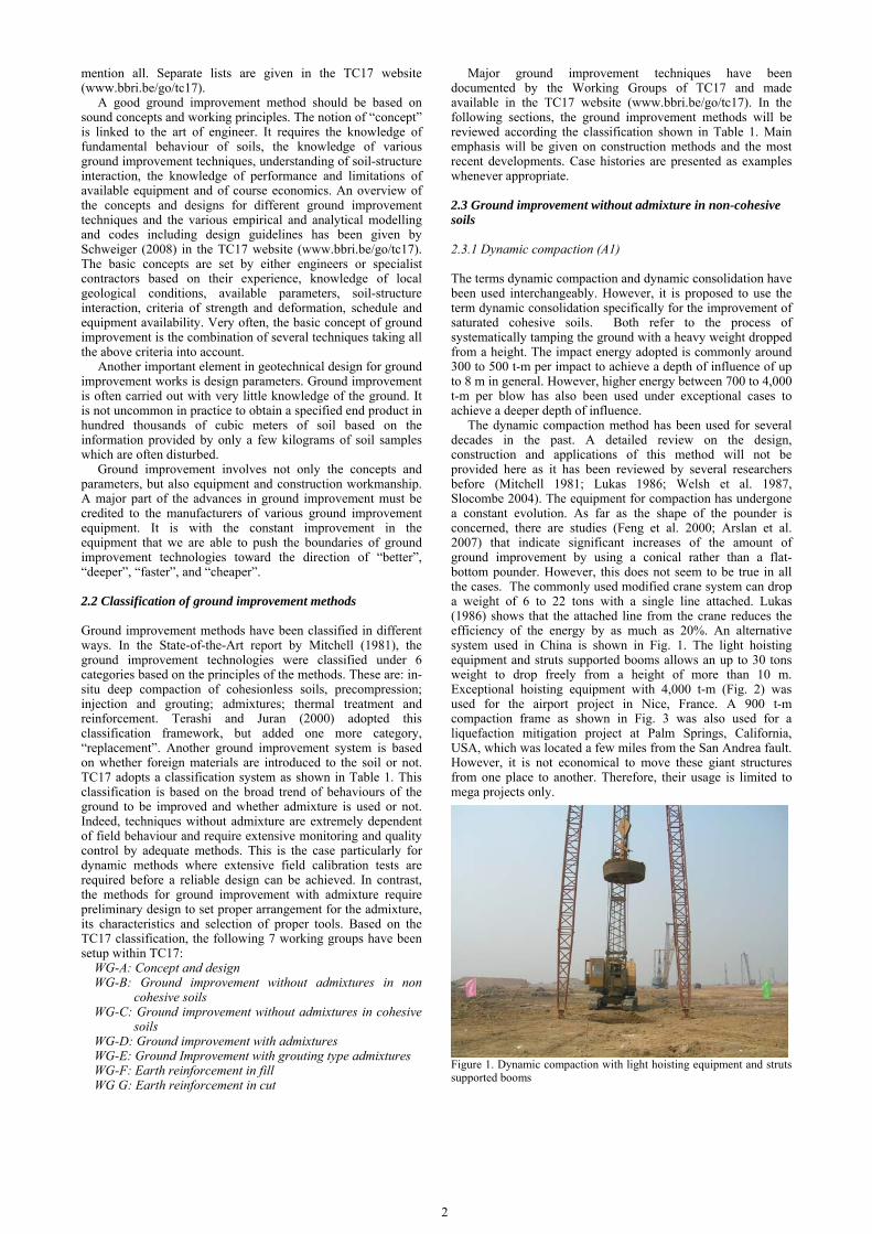
The Muller Resonant Compaction (MRC) is another deep vibratory soil compaction system (Massarsch 1991). It uses the resonance effect in soil layers to increase the efficiency of vibratory soil densification. As shown in Fig. 9, a high impedance probe is vibrated into the soil and a resonant frequency is determined by surface measurement. A heavy vibrator with variable frequency is attached to the upper end of a flexible compaction probe. The probe is inserted into the ground at a high frequency in order to reduce the soil resistance along the shaft and the toe. When the probe reaches the required depth, the frequency is adjusted to the resonance frequency of the soil layer, thereby amplifying the ground response. The probe is excited in the vertical direction and the vibration energy is transmitted to the surrounding soil along the probe surface. When resonance is achieved, the whole soil layer will oscillate simultaneously and this is an important advantage, compared to other vibratory methods. The compaction duration depends on the soil properties and on the required degree of densification to be achieved. Compaction is usually carried out in a grid pattern, in two or more passes. The grid spacing ranges typically between 3.5 to 4.5 m. This method was applied in the Changi East reclamation project (Bo et al. 2005). However, the MRC method may be over optimistically performed as far as cost-effectiveness is concerned. The weights of the vibrating beam and the vibrator require a very heavy carrier and the total power consumption is excessive as compared to other methods.
The depth of vibrocompaction is mostly confined to be within 30 m. In a recent case reported by Lauzon et al. (2006) for the foundation soils of the Peribronka hydro-electric dam in Canada, a 52 m penetration was achieved through locally dense layers and cobles using V-48 (see Table 3). For this project, three sets of vibro equipment as shown in Table 3 were compared based on mainly the capacity to penetrate greater depth and compaction efficiency. The specification for this project was a cone resistance exceeding 13 MPa.
Figure 9. MRC compaction machine and compaction probe
2.3.3 Explosive compaction (A3) The use of blasting for the densification of granular soil has been developed for many years. The principle of the method is to generate settlement of granular soil ground or fill by causing the soil to liquefy or be compacted using the shock waves and vibration generated by blasting. This method was used in the past mainly for mitigation of liquefaction in hydraulically placed sand fill. Therefore, the method has also been called explosive compaction. The development and application of this method up to the early 80s were summarised by Mitchell (1981). Explosive compaction has the advantage of low cost and ease of treating large depths. However, the method has not been widely accepted mainly because it is still based on experience rather than theory. Some field studies (Charle et al 1992; Gandhi et al. 1998; Gohl et al. 1998; 2000) have been carried out in order to understand better the blasting process. Theoretical analyses and numerical modelling using cavity expansion theories and blasting mechanics have also been done (Henrch 1979; Wu 1995; Van Court and Mitchell 1995; Gohl et al. 1998) to improve the design and analysis. In recent years, explosive compaction has also been applied to the mining sector to shake down tailings ponds for tailings consisting of essentially non-plastic silt and sand-size particles. In this way, the volume of the existing tailings is reduced, which increases the storage capacity of the tailings impoundment and minimizes the need to raise the crest elevation of the tailings containment dike. The soil types treated by the explosive compaction method range from silt tailings to gravel cobbles and boulders. Typical volume changes range from 3% to 8%. More information on explosive compaction can be found in http://www.explosivecompaction.com/index.html.
2.3.4 Electric pulse compaction (A4)
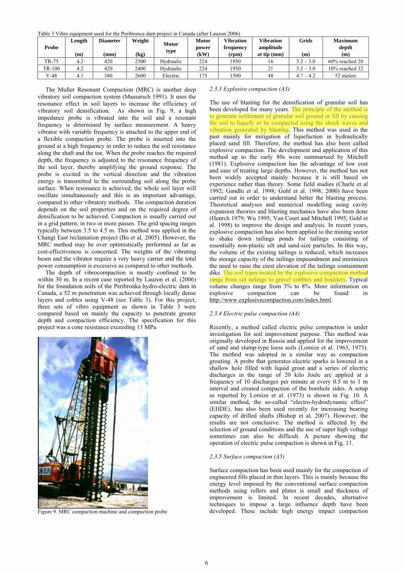
Recently, a method called electric pulse compaction is under investigation for soil improvement purpose. This method was originally developed in Russia and applied for the improvement of sand and slump-type loess soils (Lomize et al. 1963, 1973). The method was adopted in a similar way as compaction grouting. A probe that generates electric sparks is lowered in a shallow hole filled with liquid grout and a series of electric discharges in the range of 20 kilo Joule are applied at a frequency of 10 discharges per minute at every 0.5 m to 1 m interval and created compaction of the borehole sides. A setup as reported by Lomize et al. (1973) is shown in Fig. 10. A similar method, the so-called “electro-hydrodynamic effect” (EHDE), has also been used recently for increasing bearing capacity of drilled shafts (Bishop et al. 2007). However, the results are not conclusive. The method is affected by the selection of ground conditions and the use of super high voltage sometimes can also be difficult. A picture showing the operation of electric pulse compaction is shown in Fig. 11.
2.3.5 Surface compaction (A5)
Surface compaction has been used mainly for the compaction of engineered fills placed in thin layers. This is mainly because the energy level imposed by the conventional surface compaction methods using rollers and plates is small and thickness of improvement is limited. In recent decades, alternative techniques to impose a large influence depth have been developed. These include high energy impact compaction
nde
Highlight
nde
Highlight
(HEIC), rapid impact compaction (RIC), and polygonal drum method. A comparison of the working principles of different types of surface compaction methods is shown in Fig. 12. These high energy surface compaction techniques have also been adopted for the densification of hydraulic sand fill of limited depth (Mengé 2007).
1 Electric pulse plant,; 2 electric probe; 3 high-voltage cable; 4 cable
for supplying plant from 380-v line; 5 truck cane; 6 hose for delivering water; 7 3K-6 pump; 8 compacted soil 9 wetting contour
Figure 10. Electric pulse compaction method (after Lomize et al. 1973)
Figure 11. Operation of electric pulse compaction
Figure 12. Comparison of three different types of surface compaction methods (after Mengé 2007)
The common types of high energy impact compaction
machines include Landpac impact compactor, Broons and Geoqiup. One example of the Landpac impact machines is shown in Fig. 13. The weight of the rollers ranges from 7.9 tons to 16 tons. The lift or drop height varies from 0.15 to 0.23 m. The energy per impact mostly ranges around 2.5 tm. The effective compaction depth ranges around 1.5 m and the maximum depth of treatment is up to 2.5 m in some cases. Therefore, Landpac impact compactors are capable of achieving thick-lift, often single layered compaction of fills, in layers as much as 600-1500 mm. This capability allows relatively high production rates to be achieved, resulting in improved utilisation of earthmoving equipment. For the Chek Lap Kok Airport project in Hong Kong, the Landpac impact compaction
method was shown to be effective for the compaction of predominantly granular but also variable and sometimes clayey sub-grade soil to depths of up to 1.5 to 2.0 m.
Figure 13. A Landpac impact compaction machine (after Mengé 2007)
A rapid impact compaction (RIC) system is shown in Fig.
14. It compacts the ground by dropping a hammer from up to 1.2 m at a frequency of up to 40 blows per minute. The weight of the hammer is between 8 to 12 tons. Energy per impact ranges mainly between 10 to 20 t-m per blow. The diameter of the tamping foot is usually 1.5 m or 1.8 m. The compaction depth is up to 4 meters. However, the RIC method may not be suitable for saturated silts and clays (Watts and Charles 1993). Case studies showing the applications of the RIC system are given in Serridge and Synac (2007).
Figure 14. A rapid impact compaction machine (after Mengé 2007)
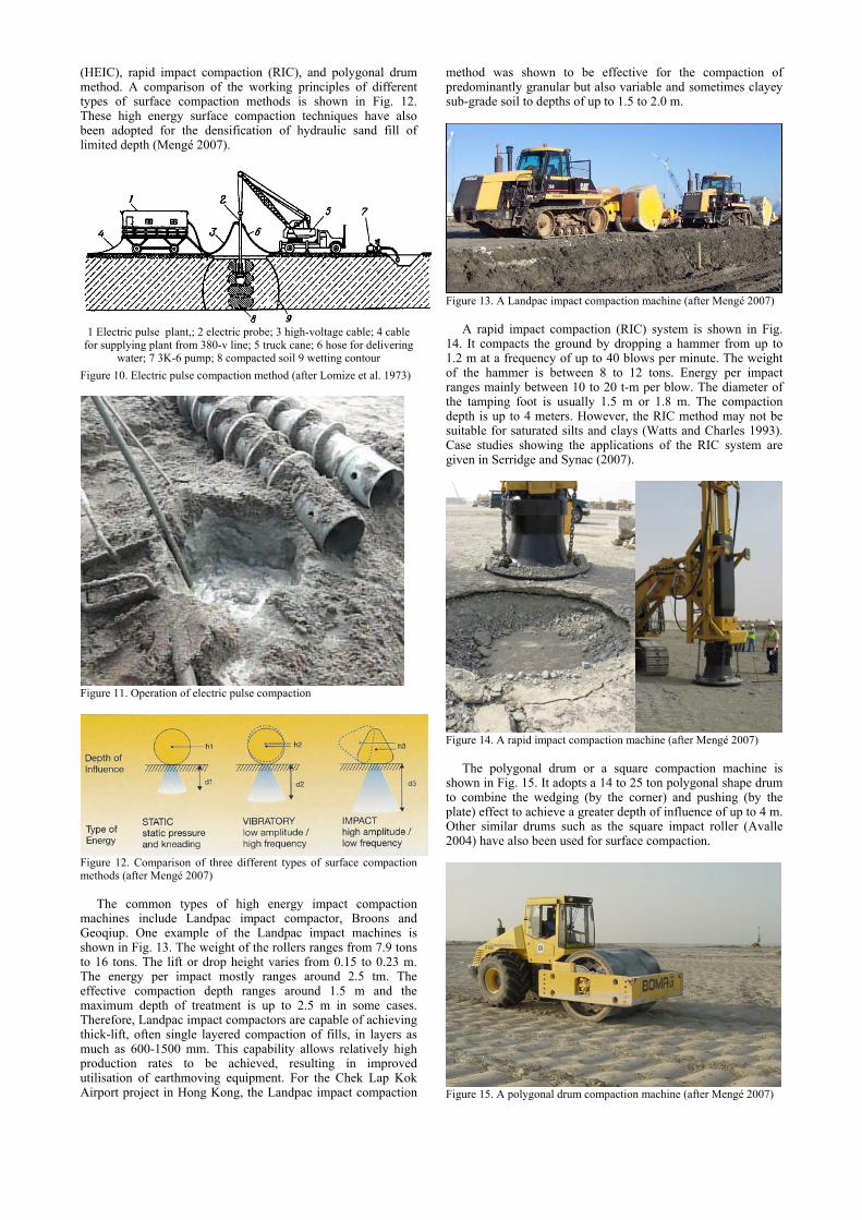
The polygonal drum or a square compaction machine is
shown in Fig. 15. It adopts a 14 to 25 ton polygonal shape drum to combine the wedging (by the corner) and pushing (by the plate) effect to achieve a greater depth of influence of up to 4 m. Other similar drums such as the square impact roller (Avalle 2004) have also been used for surface compaction.
Figure 15. A polygonal drum compaction machine (after Mengé 2007)

8
The design procedure for the impact methods is closely linked to properly tested calibration sections after ensuring that the soil characteristics are suitable for those techniques. The limit for the high energy impact techniques lays around 30 to 35% of fines in saturated sands. The proctor type of soil behaviour is followed in low to medium energy compaction in unsaturated soils. More applications of the impact compaction method will be given in Section 5.
2.3.6 Case history
As a case history, the soil improvement using the impact methods at the King Abdullah University of Science and Technology (KAUST) site in Saudi Arabia is briefly presented here. This site is extremely heterogeneous. For this reason, 76 test pits, 2,500 CPT tests, 128 SPT tests and 2,600 pressuremeter (PMT) tests were carried out. The soil profile at one section is shown in Fig. 16. The profile varies over 20 m depth from loose sand with some silt up to 6 m of near liquid-like sandy silt with a CPT tip resistance of below 0.2 MPa. Locally this layer of soil is called Sabkah. It is a fine grained deposit in lagoon type areas (Fig. 16), mostly due to storm on the lagoons or windblown in tidal areas and salty water. The adopted construction method to treat these 2,600,000 m² site in less than 8 months was based on the depth of penetration of the impact hammer at constant energy, a known procedure, in the pile driving industry. For the loose silty sand and loose to medium dense sand (shown at the right of Fig. 16), dynamic compaction was carried out. The compact energy adopted ranged from 250 to 430 t-m per blow for 175,000 impact points. A picture showing the dynamic compaction is given in Fig. 17. Dynamic replacement, as will be explained in Section 2-5, was also adopted for the improvement of Sabkah.
Figure 16. Soil profile at the KAUST site 2.4 Ground improvement without admixtures in cohesive soils
Within this category, 7 methods have been listed in Table 1. Among them, the first 4 are commonly adopted. A further elaboration of these 4 methods is given in Table 4. The advantages and disadvantages of each method are also discussed in Table 4. There are many publications and case histories on those methods and it would not be possible to mention them all in this report. Only some referred references are listed. For a more complete reference list, please go to the TC17 website: www.bbri.be/go/tc17.
2.4.1 Soil replacement or displacement method (B1)
Soil replacement or displacement is one of the oldest soil improvement methods and need no further elaboration. The method offers a quick fix to soft ground, but can be costly and environmentally unfriendly as the amount of excavation and earth moving works involved can be excessive. When dealing with very soft soil or peat mires, excavation using machine may be difficult. In this case, controlled blasting may be used to remove the soil. One such an example is given by Yan and Chu (2004). The explosive replacement method was used for a highway construction through valley zones which were underlain by a 6.0-8.5 m thick soft clay layer with an undrained shear strength of less than 20 kPa. The method is illustrated in Fig. 18. Charges are firstly installed in the soft clay to be removed. Crushed stones are piled up on the improved side of the road next to the area to be improved. When the explosive is ignited, the soft clay will be pushed out and a cavity is formed. The crushed stones will collapse into the cavity to form the base of the road. The soft clay that is blown into the air will form a liquid and flow away after it falls to the surface. After stabilization, the crushed stones form a slope of 1 in 3 or 1 in 5. The impact of the explosion also causes an instantaneous reduction in the shear strength of the soil below the level of explosion so that the crushed stones can sink easily into the deeper layer. More crushed stones can be placed to form the final ground profile. The above process can be repeated to remove and replace the soil in another section. This method has been successfully used to improve up to 8 m of soft ground in a road construction project.
Ele
vatio
n (m
)
1 = Sabkah (SM+ ML); 2 = Loose silty sand (SM); 3 = Coral; 4 = Loose to medium dense sand

Figure 17. Dynamic compaction in operation at the KAUST site
(a)
(b)
(c) Figure 18. The procedure of the explosive replacement method (after Yan and Chu 2004)
Light weight materials or premade blocks can be used as backfill to reduce the overburden load to the ground or the earth pressure to the ground. The expanded polystyrene (EPS) block geofoams have been used in infrastructure rehabilitation and construction of new facilities such as roads and embankments in recent years (Horvath 1995). One example is shown in Fig. 19. There are many advantages of using EPS block geofoams as discussed in detail by Horvath (1995) and Stark et al. (2004). However, ESP blocks need to be prefabricated off-site and thus involve transportations. The ESP blocks have to be made into
regular shapes and thus cannot be readily used to fill an irregular volume. As an alternative, lightweight fill materials made by mixing polystyrene pre-puff (PSPP) beads with soil and cement have been used. Recent applications of PSPP beads mixed lightweight fill include the use of lightweight fill made by mixing mud dredged with PSPP beads and cement for reclamation (Yoonze et al. 2004) and the use of PSPP beads mixed lightweight fill for embankment on a soft foundation (Ma 2003). The PSPP beads mixed lightweight fill can be made on site into a slurry form and poured to anywhere before it hardens (Liu et al. 2006). Thus it is particularly suitable to be used to fill cavities, underground openings of irregular shapes or for rehabilitation works. However, the PSPP beads mixed lightweight fill can be more expensive as cement is used and extra manpower or machines are required for mixing.
(a)
(b) Figure 19. Use of EPS geofoam as a lightweight fill material for highway embankments on the Boston’s Central Artery/Tunnel Project (a) concept design (after Riad et al. 2004) and (b) during construction (after http://www.tfhrc.gov/pubrds/04mar/08.htm)

10
Table 4. Commonly used ground improvement methods for cohesive soils without admixtures Type Method Description / Mechanisms Typical Applications Advantages Limitations
B1
Rep
lace
men
t / d
ispl
acem
ent B
1-1
Rep
lace
men
t Ground is improved by removing poor soil and replacing it with suitable materials. Light weight materials can be used as backfill to reduce the load or earth pressures.
The method can be used when the area to be improved is limited and when only the top few meters of soil needs to be improved.
1). It can be applied to all types of soil that can be excavated easily; 2). Immediate improvement is achieved; 3). The bearing capacity and settlement of the soil can be controlled.
The method is expensive and limited to shallow depth of 3 to 4 m only.
B1-
2
Dis
plac
e-m
ent
Soft soil is improved by using good soil to displace soft soil without removing the soft soil completely.
The method is suitable to soft, swampy area where excavation is difficult and when the depth of soil to be improved is limited.
1). It is less expensive than the replacement method; 2). It can be used when the soil to be replaced is very soft or highly organic such as muck and peat.
Soft soil cannot be completely replaced. Some soft soil pockets exist. Therefore, quality control can be difficult.
B1-
3
Expl
osiv
e re
plac
emen
t
Explosive is used to remove soft soil and causes a pile of rock to fall into the cavity created by blasting.
It can be used when the soft soil to be removed is less than 8 m and gravels, rocks or crushed stones are available.
1). It is less expensive than the soil replacement method; 2). The soil replacement ratio is higher than that achieved by soil displacement method.
1). A relative complete replacement can only be achieved for the top soil depending on the position of the explosives; 2). It is not suitable to urban constructions; 3). Quality control can be difficult.
B2
& B
3 Pr
eloa
ding
B2-
1
Prel
oadi
ng u
sing
fill
Preloading is a process to apply surcharge load on to the ground prior to the placement of structure or external loads to consolidate the soil until most of the primary settlement has occurred so as to increase the bearing capacity and reduce the compressibility of weak ground.
This method is applicable to all soils (but mainly clay) where consolidation is required to reduce the void ratio and water content of the soil. It can be used as a mean to reduce secondary compression of the soil.
The method is inexpensive if a large area is improved and the fill materials can be reused as part of the construction materials.
1). The method is time consuming; 2). Stage construction is required if the ground is weak and/or the fill is too high.
B2-
2
Prel
oadi
ng
usin
g fil
l w
ith v
ertic
al
drai
n
The method is the same as B2-1, except that vertical drains are used to provide radial drainage and accelerate the rate of consolidation by reducing the drainage paths.
The method is applicable to soils having low permeability or when the compressible soil layer is thick.
Rate of consolidation can be greatly accelerated. The construction time can be controlled by adjusting the spacing of the drain.
The method may not be applicable when the construction schedule is very tight or when the ground is so soft that vertical drains cannot be installed.
B2
& B
3 Pr
eloa
ding
B3-
1
Vac
uum
pre
load
ing
with
ve
rtica
l dra
ins
The method is the same as B2, except the surcharge is applied using vacuum pressure. The vacuum pressure is usually distributed through vertical drains. It also provides immediate stability to the system. The treated soil is enclosed by an air- and watertight barrier to all directions.
The method is applicable to ground consists of mainly saturated low permeability soils. The method can be used when there is a stability problem with fill surcharge. This method can also be used to extract polluted ground pore water, if required.
1). The method does not require fill material; 2). The construction period can be shorter, as no stage loading is required; 3). It may be more economical than using fill surcharge; 4) The vacuum brings immediate stability to the system.
1). This method causes inward lateral movement and cracks on the ground surface which may affect surrounding buildings or structures; 2). The vacuum pressure is limited to 50 - 90 kPa, depending on the system adopted.
B3-
2
Com
bine
d fil
l and
va
cuum
pre
load
ing
The method is a combination of B2-2 and B3-1 when a surcharge more than the vacuum pressure is required.
The same as for B2 and B3-1.
1). Construction time can be much reduced as compared to staged loading using fill surcharge alone; 2). The lateral movement of soil can be controlled by balancing the amount of vacuum and fill surcharge used. 3). The vacuum brings immediate stability to the system.
1). It is technically more demanding than B2 and B3-1; 2). Data interpretation is also more complicated.
B4
Impr
oved
DC
m
etho
ds
B4-
1
Dra
inag
e en
hanc
ed
dyna
mic
com
pact
ion
(DC
) met
hod
This method improves the soil properties by combining the DC method with vertical drains which facilitates the dissipation of pore water pressure generated during DC.
This method can be used to improve the bearing capacity of soft soil with low permeability.
1). The method made the application of DC possible to fine-grained soil; 2). The duration of soil improvement can be reduced.
1). The method may only work for cohesive soil with relatively low plasticity index; 2). The compaction energy applied has to be within a certain limit, so that the depth of improvement is limited; 3). The technical has not been fully developed. Thus, the success of the method cannot always be guaranteed.
B4-
2
Vac
uum
enh
ance
d or
de
-wat
erin
g +
dyna
mic
com
pact
ion
(DC
) met
hod
This method improves the soil properties by conducting DC and applying vacuum or de-watering alternately for a number of times. The vacuum facilitates a quick dissipation of water pressure generated by DC.
This method can be used to improve soft clay or soft ground with mixed soil.
1). The soil improvement time can be reduced; 2). Can be applicable to most types of soil.
1). The method has not been fully established. Thus, the success of the method cannot always be guaranteed; 2). The depth of improvement is normally limited to 8 m.

2.4.2 Preloading using fill and prefabricated vertical drains (B2)
Preloading is one of the most common methods adopted for the treatment of soft cohesive soils. Prefabricated vertical drains (PVDs) or sand drains are almost always used together with this method nowadays. Depending on the way preloading is applied, the method can be subdivided into preloading using fill, preloading using vacuum pressure, and combined fill and vacuum preloading methods, as described in Table 4.
The method of preloading using fill has been used for many years in the past and has been considered one of the mature soil improvement methods. Major progress in this method has been made since PVDs were introduced as part of the preloading techniques. As a result of numerous research and field studies, the PVD technique has been established in a systematic way from analyses to construction. The past developments have been summarised in many publications, for example, Holtz et al (1991), Bo et al. (2003), Moseley and Kirsch (2004) and Raison (2004). Many case histories have also been published, e.g, Hansbo (2005) and Moh and Lin (2005). Therefore, a review on the recent development in PVDs and preloading will not be made in this report.
However, there are several new developments on PVDs that are still worth mentioning. The first is the development of design codes or design guides. These include the Code of Practice for Installation of Prefabricated Drains and the Quality Inspection Standard for Prefabricated Drains developed in China (JTJ/T256-96 1996, JTJ/T257-96 1996) and the European Standard on Execution of Special Geotechnical Works — Vertical Drainage (prEN 15237, 2005). Second is the emergence of the new types of drains, such as electric vertical drain with a metal foil embedded in the drains as anodes and cathodes for electro-osmosis (Shang 1998; Bergado et al. 2000) and the integrated drain with the filter glued to the code using heat melting (Liu and Chu 2009), as shown in Fig. 20. The integrated drain offers a higher tensile strength and discharge capacity than the ordinary drain of the same materials and same dimensions. There are also PVDs for geoenvironmental use. For example, PVDs have been used to help in providing a vapour extraction system (Schaefer et al. 1997). For environmental usage, the PVD materials may need to be specially designed to resist acid corrosion (Chu et al. 2005).
(a)
(b) Figure 20. Types of prefabricated vertical drains (a) separated core and filter; (b) core and filter heat adhered together (after Liu and Chu 2009)
Quality control is also one of the important aspects in the
constructions involving the use of PVDs. Different methods that can be adopted for quality control tests and the rationale behind each method is explained in Chu et al. (2004). To measure directly the length of PVDs installed in the ground, PVDs with scales printed on the filter have been used. Another method of using one or two thin copper wires embedded in the filters has also been proposed (Liu et al. 2009).
In recent years, there have been more offshore projects requiring PVDs being installed offshore from a barge. For shallow water, PVDs may be installed from a pontoon, see Fig. 21a as an example. For relatively deep water, sand drain or PVD installation barges have been used (Kitazume, 2007). As an example, the barge used for a breakwater project in
Shanghai, China, for installing 12 PVDs simultaneously is shown in Fig. 21b (Yan et al. 2009).
It should be pointed out that PVDs have also been used as horizontal drains in some projects. One example is given by Shinsha et al. (1991) for a project in Japan in which horizontal wick drains were used for the consolidation of freshly deposited slurry-like dredged fill. Another example is given by He and Shen (2001) for a power station project on the north bank of the Meghna River in Bangladesh where horizontal wick drains were used with vibrating roller compaction for the improvement of dredged silty/fine sand placed layer by layer.
Figure 21(a) Offshore vertical drain installation from a boat or floating platform
Figure 21 (b). Offshore vertical drain installation barge (after Yan et al. 2009)
2.4.3 Preloading using vacuum (B3)
When the ground is very soft or when the fill surcharge has to be applied in stages to maintain the stability of the fill embankment, the vacuum preloading method becomes a good alternative. Vacuum preloading is also used when there is no fill or the use of fill is costly, when there is no space on site to place the fill and when slurry or soft soil is used as fill for reclamation.
It has been 56 years since the idea of vacuum preloading was proposed by Kjellman in 1952. Since then, the vacuum preloading method has evolved into a mature and efficient technique for the treatment of soft clay. This method has been successfully used for many soil improvement or land reclamation projects all over the world (Holtz 1975; Chen and Bao 1983; Cognon 1991; Bergado et al. 1998; Chu et al. 2000; Yee et al. 2004; Indraratna et al. 2005). With the merging of new materials and new technologies, this method has been further improved in recent years.
100±2 mm
5±1 mm
nde
Highlight
nde
Highlight
nde
Highlight
nde
Highlight

12
The first large scale application of vacuum preloading was probably made in the early 80s in China for the development of the Tianjin Harbour (Chen and Bao 1983). The vacuum preloading was required because clay slurry was used for reclamation due to a shortage of granular fill materials there. In adopting this technique, sand drains (in the past) and prefabricated vertical drains (PVDs) were used to distribute the vacuum pressure and discharge pore water. In theory, a vacuum load of 90 kPa can be applied. However, in practice, the real vacuum pressure applied is normally lower than this. An overview of the principles and techniques of the Tianjin method and their applications have also been given by Chu and Yan (2005). Thousands of hectares of land have been reclaimed in Tianjin using this method (Chen and Bao 1983; Yan and Chu 2005). A number of case histories have been published (Chen and Bao 1983; Choa 1989; Tang and Shang 2000; Chu et al. 2000; Yan and Chu 2003; 2005). This method has been widely applied in other parts of China and other countries.
The schematic arrangement of the vacuum preloading system adopted in Tianjin is shown in Fig. 22. PVDs are normally used to distribute vacuum load and discharge pore water. The soil improvement work using the vacuum preloading method is normally carried out as follows. A 0.3 m sand blanket is first placed on the ground surface. PVDs are then installed on a square grid at a spacing of 1.0 m in the soft clay layer. Corrugated flexible pipes (50 to 100 mm diameter) are laid horizontally in the sand blanket to link the PVDs to the main vacuum pressure line. The pipes are perforated and wrapped with a nonwoven geotextile to act as a filter layer. Three layers of thin PVC membranes are laid to seal each section. Vacuum pressure is then applied using jet pumps. The size of each section is usually controlled in the range of 5,000 to 10,000 m2. Field instrumentation is an important part of the vacuum preloading technique, as the effectiveness of vacuum preloading can only be evaluated using fielding monitoring data. Normally piezometers, settlement gauges and inclinometers are used to measure the pore water pressure changes, the settlement at ground surface and/or different depths in the soil and the lateral displacement. More details are presented in Chu et al. (2000) and Yan and Chu (2003).
Figure 22. Vacuum preloading system used in Tianjin, China (after Chu et al. 2000)
In Europe, the Menard Vacuum Consolidation system has been developed by Cognon (1991). The detail of this system can be found in Varaksin et al. (1994) and Yee et al. (2004). The general principle following this French method is presented in Fig. 23. The uniqueness of this system is the dewatering below the membrane which permanently keeps a gas phase between the membrane and the lowered water level. Therefore, the Menard Vacuum Consolidation system adopts a combined dewatering and vacuum preloading methods to maintain an unsaturated pervious layer below the membrane.
ISOTROPIC CONSOLIDATION
Soft clay (k < 10-9 m/sec)
ISOTROPIC CONSOLIDATION
Soft clay (k < 10-9 m/sec)
Figure 23. The Menard Vacuum Consolidation system
When the total area has to be subdivided into a number of
sections to facilitate the installation of membrane, vacuum preloading can only be carried out one section after another. This may not be efficient when the vacuum preloading method is used for land reclamation over a large area. One way to overcome this problem is to connect the vacuum channel directly to each individual drain. In this way, the channel from the top of the PVD to the vacuum line is sealed. Hence, a sand blanket and membranes are not required. This system has been developed in the Netherlands (Kolff et al. 2004). This so-called BeauDrain system adopts a tubing system as shown in Fig. 24. In this method, each vertical drain is connected to the horizontal drains keeping a flooded area to maintain a vacuum depression (Kolff et al. 2004). This method has been used for the construction of the new Bangkok Suvarnabhum International Airport (Seah 2006; Saowapakpiboon et al. 2008). However, as such a system does not provide an airtight condition for the entire area, high efficiency is difficult to be achieved. The vacuum pressure applied for the Suvarnabhum Airport project was only 50 kPa or lower (Seah 2006). This method also only works when the soil layer to be improved is dominantly low permeability soil.
(a) (b) Figure 24. (a) PVD and tubing for vacuum preloading (after Seah 2006) and (b) field operation (after Saowapakpiboon et al. 2008)
Another method to do away with the membrane is to use the
so-called low level vacuum preloading method (Yan and Cao 2005). This method is schematically illustrated in Fig. 25. When clay slurry is used as fill for land reclamation, the vacuum pipes can be installed at the seabed or a level a few meters below the
1, drains; 2, filter piping; 3, revetment; 4, water outlet; 5, valve; 6, vacuum gauge; 7, jet pump; 8, centrifugal pump; 9, trench;
10, horizontal piping; 11, sealing membrane.
nde
Highlight

ground surface. In this way, clay slurry fill can be placed on top of the vacuum pipes. As clay has a low permeability, the fill material will provide a good sealing cap and membranes will not be required. However, this method is not problem-free. Tension cracks can develop on the surface when the top layer is dried. The vacuum pressure may not be distributed properly unless a drainage blanket is used at the level where the drainage pipes are installed or the individual drains are connected to the vacuum pipes directly. It is also difficult to install drainage pipes or panels underwater. Nevertheless, this method does not require the construction of inner dikes for subdivision and thus cuts down the project costs and duration substantially.
Figure 25. Membraneless vacuum preloading method (after Chu et al. 2008)
The vacuum preloading method may not work well when the
subsoil is inter-bedded with sand lenses or permeable layers that extend beyond the boundary of the area to be improved, such as the improvement of soft soil below sand fill for reclaimed land. In this case, a cut-off wall is required to seal the entire area to be treated. One example is given by Tang and Shang (2000), in which a 1.2 m wide and 4.5 m deep clay slurry wall was used as a cut-off wall in order to improve the soft clay below a silty sand layer. However, installation of cut-off walls is costly when the total area to be treated is large. An alternative method is to use PVDs with impermeable plastic sleeve for the section of the PVD that passes through the permeable layer. However, this is workable only when we know fairly accurately the thickness of the permeable layer over the whole site.
It should be pointed out that vacuum preloading creates an inward lateral displacement at the boundary of the loaded area. This leads to ground cracks and adjacent effect. For the same reason, the containment dike used in a vacuum preloading project (such as in Fig. 25) can be afford to be designed with a smaller safety margin.
Vacuum preloading can also be used in offshore underwater. One example is given in Fig. 26 based on a project in Tianjin, China. In this method, vertical drains, sand blanket, horizontal pipes and membranes were placed underwater. A jet pump was placed in water to reduce the head loss. However, the placement of membrane offshore is difficult. One way to overcome this problem is to replace the membrane by a layer of dredged clay slurry. Another method was described by Van Impe et al. (2001) in which dredged silt material was used as a cover for horizontal drains. A special horizontal drain installation plough was also designed and used for this project (Van Impe et al. 2001).
2
1
3 45 6
7 811
9
10
1 sand drain; 2 sand blanket; 3 horizontal pipes; 4 membranes; 5
connector to vacuum; 6 vacuum valve and gauge; 7 vacuum line; 8 jet pump; 9 water line; 10 centrifugal pump; 11 boat
Figure 26. Schematic arrangement for underwater vacuum preloading (modified from Yang et al. 1987)
2.4.4 Preloading using combined fill and vacuum surcharge (B3)
When surcharge higher than the maximum value that the vacuum pressure can provide, a combined vacuum and fill surcharge can be applied. In this case, the fill surcharge is applied after the ground has been consolidated to gain adequate strength. One example is shown in Fig. 27. As the fill surcharge generates excessive pore-water pressure higher than the hydrostatic or initial in-situ pore-water pressure, as shown in Fig. 28, the vacuum pressure applied may expedite the dissipation of excess pore-water pressure and make the combined fill and vacuum preloading method more effective than using vacuum or fill surcharge alone for the same amount of total surcharge. However, this speculation has yet to be verified by field tests. As shown in Fig. 28, the pore-water pressure is reduced from the excess pore-water pressure level to a level near the suction line and the amount of reduction in pore-water pressure is almost the same along the entire depth. This implies that the suction applied along the entire depth was almost the same and a well resistance was small, if existed. The same has been observed in other vacuum preloading projects with an improvement depth of up to 20 m (Chu et al. 2000; Yan and Chu 2003). In all these projects, PVDs with a sufficiently large discharge capacity were used.
Figure 27. Loading sequence of combined fill and vacuum preloading and ground settlement measured (after Yan and Chu 2005)
Figure 28. Pore-water pressure distributions with depth at different durations (after Yan and Chu 2005)
Fill surcharge

14
As the vacuum pressure creates an inward lateral movement and the fill an outward movement, the combined vacuum and surcharge preloading can be used as a method to control the lateral movement. Attempts to use this technique to control the lateral movement of diaphragm wall have been made (Miyazaki et al. 2005).
2.4.5 Dynamic consolidation with enhanced drainage or vacuum (B4)
When the term “dynamic consolidation” was coined by Menard (Menard and Broise 1975), he envisaged the method would be used for fine-grained soils as well. Although there are a few successful cases, it is generally believed that the dynamic compaction (DC) method using heavy tamping is not suitable to fine-grained soils, particularly for soils with a plasticity index larger than 10 (Mitchell 1981; Charles and Watts 1982; Smoltczyk 1983).
Since the late seventies, attempts have been made in China to apply the DC method to treat soft ground in a number of projects and some successes have been achieved (Qian and Li 1983; Zhang and He 1987). In these cases, sand drains or PVDs were used to facilitate the dissipation of pore pressures. However, the results vary from site to site and no mature technique has been established. In a recent case study reported by Zheng et al. (2004), the following guidelines were drawn for compaction of soft clay ground using DC: 1) A proper drainage system has to be installed before
compaction. The use of PVDs with sand blanket appears to be an effective drainage system.
2) The compaction should begin with low compaction energy for the first pass and then increase the energy gradually for the subsequent passes. The rationale is to consolidate the top soil to form a “hard crust” first. Once a “hard crust” is formed, larger compaction energy can be applied and soil at a deeper depth can be compacted. This is totally different from the procedure used for compacting granular soil in which higher compaction energy is suggested to be used for the first few blows to extend the compaction as deep as possible (Broms 1991). A compaction scheme with compaction energy gradually increased from 500 to 800, and then 1600 kNm appears to be suitable for the compaction of soft silty clay.
3) It is more effective to use more passes, but only 1 - 3 numbers of blows per pass for compaction.
4) A resting period between each pass of compaction is required to allow the pore-water pressure to dissipate. For the case studied, a resting period of 4 to 7 days appears to be sufficient. A case study was presented by Zheng et al. (2004) and Chu
et al. (2005) in which the drainage enhanced dynamic consolidation method was used to treat a site consisting of soft silty clay of 2 to 7 m deep and a sandy clay below. The PVD spacing was 1.7 to 2 m in a square grid. The sand blanket was 1.5 m thick. The CPT tip resistance has increased 2 to 3 time up to 5.5 m after dynamic compaction. Similar techniques have been used in other countries (Perucho and Olalla 2006; Lee and Karunaratne 2007).
A variation of the above technique is to use deep dewater wells together with dynamic compaction for soft clay (Xu et al. 2003). In this method, the soil is compacted using surface compaction or small energy dynamic compaction first to generate excess pore-water pressures. Deep well points are then installed to dissipate the excess pore-water pressures. After the excess pore-water pressures are reduced, the deep well points are removed and the second round of dynamic compaction and dewatering are carried out. This method is more effective than the use of PVDs alone as suction creates a much higher hydraulic gradient to speed up the dissipation of excess pore water pressure. The well points can also be installed at the points where the excess pore water pressure is the highest. The
holes left after the withdrawal of the pipes for dewatering also helps in the dissipation of excess pore-water pressure generated in the subsequent compaction. This method has been used for a number of projects in China. However, the method may only be effective when the depth of soil to be improved is less than 8 m which is inherently the limitation of dynamic compaction with the common level of compaction energy. It may also be less effective for soils with high plasticity index (probably higher than 20).
2.4.6 Electro-osmosis or electro-kinetic consolidation (B5)
Electro-osmosis is a technique developed by Casagrande in 1941. The principle of the technique is that when a direct current (DC) voltage is applied to soil via electrode poles, the soil pore-water will be attracted towards the direction of the negative terminal (cathode) due to the interaction of the electric field, the ions in the pore-water and the soil particles. If drainage is provided at the cathode and prohibited at the anode, consolidation will be induced by electro-osmosis, resulting in the lower soil water content, higher shear strength and lower compressibility. In addition, electrochemical reactions associated with an electro-osmotic process alter the physical and chemical properties of the soil and lead to a further increase in shear strength (Mitchell 1993). The method is considered suitable for projects that require a rapid improvement in the properties of soft clayey soils. Successful field tests using electro-osmosis to strengthen silty clays and soft sensitive clays, stabilize earth slopes, and reinforce steel piles installed in clayey soils have been published by Bjerrum et al. (1967), Casagrande (1983), and Lo et al. (1991).
Electro-kinetic stabilization is a hybrid between electro-osmosis and chemical grouting. The infusion of certain stabilization chemicals into silty and sandy soils is made more efficient by the application of an electrical potential difference to the soil mass. The procedure is more effective in silty soils that are otherwise difficult to grout ordinarily. Information on this technique can be found in Broms (1979) and Mitchell (1981). More recently, electrokinetic assisted chemical stabilization has been applied to offshore calcareous soils (silts and sands) for stabilization of petroleum platforms (Mohamedelhassan and Shang 2003; Shang et al. 2004). In recent years, there is also an increasing interest in using electro-kinetic technology for site remediation problems (Wang et al. 2004).
The concept of electrically conductive geosynthetic materials was also introduced by Jones et al. (1996). A new technique to combine electro-kinetic and geosynthetics (EKG) to make electrically conducting geosynthetics has been developed by Jones et al. (2005) and Glendinning et al. (2005a). The EKG materials offer sufficient electrical conduction to allow the application of electrokinetic techniques so that water and chemical species can be transported within fine-grained low permeability soils. A case study for the construction of a retaining wall using EKG materials was presented by Glendinning et al. (2005a; 2005b).
2.4.7 Thermal stabilisation (B6)
(1) Soil improvement by heating Heating causes permanent changes in soil properties and renders the material hard and durable. Laboratory studies have shown that an increase in temperature increases settlements of clays under a given applied stress. After cooling to the ambient temperature, a thermal vertical overconsolidation is generated (Leroueil and Marques 1996; Abuel-Naga et al. 2007). The idea of preconsolidation of clay using a combined vacuum and heating method in cold region has been attempted by Marques and Leroueil (2005) in Quebec. Another field trial was carried out recently by Pothiraksanon et al. (2008) in which hot water was circulated into the PVDs to elevate the ground temperature.
However, these methods are still in the experimental stage and there are no large scale field applications yet.
Another application of heating method is the so-called heat exchange pile which has been discussed in detail by Brandl (2006) and Laloui et al. (2005). Some other methods of using heat for soil improvement purposes have been described in Van Impe (1989).
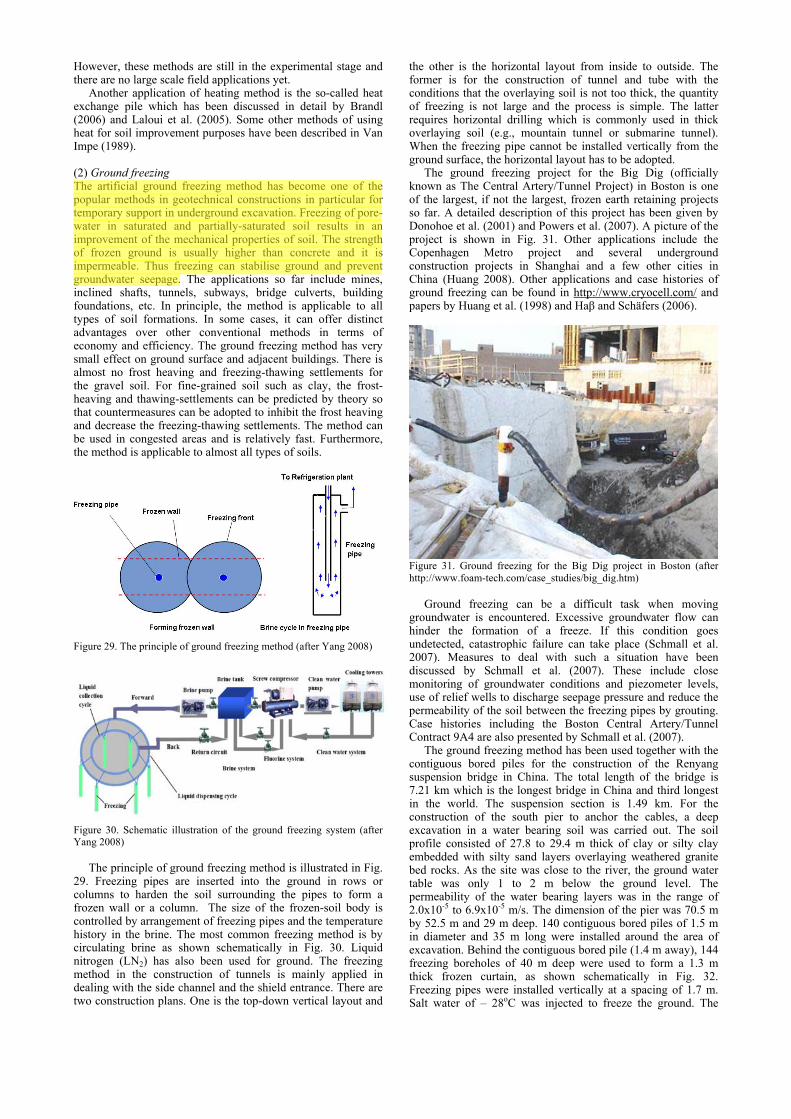
(2) Ground freezing The artificial ground freezing method has become one of the popular methods in geotechnical constructions in particular for temporary support in underground excavation. Freezing of pore-water in saturated and partially-saturated soil results in an improvement of the mechanical properties of soil. The strength of frozen ground is usually higher than concrete and it is impermeable. Thus freezing can stabilise ground and prevent groundwater seepage. The applications so far include mines, inclined shafts, tunnels, subways, bridge culverts, building foundations, etc. In principle, the method is applicable to all types of soil formations. In some cases, it can offer distinct advantages over other conventional methods in terms of economy and efficiency. The ground freezing method has very small effect on ground surface and adjacent buildings. There is almost no frost heaving and freezing-thawing settlements for the gravel soil. For fine-grained soil such as clay, the frost-heaving and thawing-settlements can be predicted by theory so that countermeasures can be adopted to inhibit the frost heaving and decrease the freezing-thawing settlements. The method can be used in congested areas and is relatively fast. Furthermore, the method is applicable to almost all types of soils.
Figure 29. The principle of ground freezing method (after Yang 2008)
Figure 30. Schematic illustration of the ground freezing system (after Yang 2008)
The principle of ground freezing method is illustrated in Fig.
29. Freezing pipes are inserted into the ground in rows or columns to harden the soil surrounding the pipes to form a frozen wall or a column. The size of the frozen-soil body is controlled by arrangement of freezing pipes and the temperature history in the brine. The most common freezing method is by circulating brine as shown schematically in Fig. 30. Liquid nitrogen (LN2) has also been used for ground. The freezing method in the construction of tunnels is mainly applied in dealing with the side channel and the shield entrance. There are two construction plans. One is the top-down vertical layout and
the other is the horizontal layout from inside to outside. The former is for the construction of tunnel and tube with the conditions that the overlaying soil is not too thick, the quantity of freezing is not large and the process is simple. The latter requires horizontal drilling which is commonly used in thick overlaying soil (e.g., mountain tunnel or submarine tunnel). When the freezing pipe cannot be installed vertically from the ground surface, the horizontal layout has to be adopted.
The ground freezing project for the Big Dig (officially known as The Central Artery/Tunnel Project) in Boston is one of the largest, if not the largest, frozen earth retaining projects so far. A detailed description of this project has been given by Donohoe et al. (2001) and Powers et al. (2007). A picture of the project is shown in Fig. 31. Other applications include the Copenhagen Metro project and several underground construction projects in Shanghai and a few other cities in China (Huang 2008). Other applications and case histories of ground freezing can be found in http://www.cryocell.com/ and papers by Huang et al. (1998) and Haβ and Schäfers (2006).
Figure 31. Ground freezing for the Big Dig project in Boston (after http://www.foam-tech.com/case_studies/big_dig.htm)
Ground freezing can be a difficult task when moving
groundwater is encountered. Excessive groundwater flow can hinder the formation of a freeze. If this condition goes undetected, catastrophic failure can take place (Schmall et al. 2007). Measures to deal with such a situation have been discussed by Schmall et al. (2007). These include close monitoring of groundwater conditions and piezometer levels, use of relief wells to discharge seepage pressure and reduce the permeability of the soil between the freezing pipes by grouting. Case histories including the Boston Central Artery/Tunnel Contract 9A4 are also presented by Schmall et al. (2007).
The ground freezing method has been used together with the contiguous bored piles for the construction of the Renyang suspension bridge in China. The total length of the bridge is 7.21 km which is the longest bridge in China and third longest in the world. The suspension section is 1.49 km. For the construction of the south pier to anchor the cables, a deep excavation in a water bearing soil was carried out. The soil profile consisted of 27.8 to 29.4 m thick of clay or silty clay embedded with silty sand layers overlaying weathered granite bed rocks. As the site was close to the river, the ground water table was only 1 to 2 m below the ground level. The permeability of the water bearing layers was in the range of 2.0x10⁻⁵ to 6.9x10⁻⁵ m/s. The dimension of the pier was 70.5 m by 52.5 m and 29 m deep. 140 contiguous bored piles of 1.5 m in diameter and 35 m long were installed around the area of excavation. Behind the contiguous bored pile (1.4 m away), 144 freezing boreholes of 40 m deep were used to form a 1.3 m thick frozen curtain, as shown schematically in Fig. 32. Freezing pipes were installed vertically at a spacing of 1.7 m. Salt water of – 28oC was injected to freeze the ground. The
nde
Highlight

16
frozen curtain acted to stop seepage, reduce the uplift pressure at the base of excavation and the earth pressure on the wall. 74 grouting pipes were also used to grout the soil at the bottom of the freezing zone to reduce the effect of seepage water on the formation of freezing curtain. To reduce the horizontal forces generated as a result of the ground freezing, 284 mud filled pressure releasing holes of 25 cm in diameter were also drilled in the inner side of the frozen curtain. A similar technique was also adopted for the 3.799 km long Hukou suspension bridge in Jiangxi, China. More examples on the use of ground freezing method are given by Jessberger et al. (2003) and in Section 3.
(a)
(b) Figure 32. Application of the ground freezing for deep excavation (a) schematic illustration (b) during construction (courtesy of P. Yang)
(3) Utilization of permafrost
An extension of the ground freezing method is the use of natural permafrost for stability of geotechnical structures. Special techniques have been adopted for the construction of the Qinghai-Tibet Railway in China. For this 1138 km long railway project, 550 km runs though the continuous permafrost region and 82 km is in the sporadic permafrost region. Therefore, there are enormous economic benefits to utilize the permafrost in the construction of the railway embankment.
(a) Thermal piles
(b) Shading boards
(c) Crushed rock based embankment
(d) Ventiduct Figure 33. Techniques adopted for the Qinghai-Tibet Railway construction to maintain the permafrost of the ground in continuous permafrost regions (courtesy of Z.M. Zhang)
Some of the techniques adopted for this project include: (1)
thermal piles (Fig. 33a) which are mainly through the gas-liquid phase convection of the working medium inside it to bring the heat out from the permafrost beneath embankment in winter to decrease the soil temperature and to enhance the thermal stability of the embankment. This method has also been adopted in other countries; (2) shading boards parallel with the side slope (Fig. 33b); (3) crushed rock based embankment (Fig. 33c) which is mainly through enforced air convection to enhance the heat release from embankment in winter in order to decrease the soil temperature beneath the embankment; and (4) ventiduct (Fig. 33d) which is through the enforced convection inside to increase the release of heat from the soil within the embankment in winter. It should be noted that the ventiduct also increases the

heat entering into the soil in summer. However, winter-time in the Qinghai-Tibet plateau is much longer than summer-time, so the total amount of heat release is much greater than that of heat absorption annually.
2.4.8 Hydro-blasting compaction (B7)
Hydro-blasting compaction is an approach that has been proved effective in the treatment of collapsible loess soils in Bulgaria. Using the collapsible properties of the soil, water is firstly introduced to the soil to induce settlement and then blasting is used to compact the soil further. A case study has been presented by Jefferson et al. (2005). As shown in Fig. 34, drain-explosive boreholes were drilled as a triangle pattern of 3.5 m spacing. After the preliminary wetting treatment, explosives were installed into each borehole at an alternate depth of 7 or 13 m. Explosives were detonated in sequence, with those in the lower level detonated first, followed by those in the upper level.
1 – 1st level drain-explosive boreholes; 2 – 2nd level drain-explosive
boreholes; 3 – explosive; 4 – drain borehole; 5 – confines of the moistened zone; 6 – water table in the excavation; 7 – deep bench mark Figure 34. A loess deposit site where hydro-blasting compaction is adopted: (after Jefferson et al 2005).
2.4.9 Case history
As a case history, the reclamation and soil improvement works at the Airbus A380 industrial platform site in Hamburg, Germany is briefly introduced. As shown in Fig. 35a, the site covered approximately 140 hectares. It was a former sand quarry mined in the first half of the 20th century and was abandoned since then. It was heavily silted by the Elbe River and thus heavily polluted. The environmental consideration required a construction method that would cause minimum lateral displacement of the mud deposits. All water discharged from the consolidation of the mud must also be treated and cleaned as there was presence of large concentration of ammonium and heavy metals. The site was under tidal influence. The soil profile is shown in Fig. 35b. The thickness of the compressible layers varied from 5 to 14 m and the thickness of the very soft surface mud layer was 3 to 12 m. The only accessibility to this site was by floating flat bottom barges. Even with this, the accessibility was limited to 1½ hour per tidal movement. Based on a final elevation of +5.5 m excluding lateral displacement, the calculated vertical deformation under the fill load ranged from 2.5 to 4 m. This did not include secondary compression which could not be ignored as organic deposits were present at the site.
This project was implemented under three tenders. The first one was for the design and construction of a permanent quay wall and a peripheral temporary sheetpile wall for containing the mud and isolating the site from the tidal influence, see Fig. 36(a). The second tender was for reclamation works. It required the raising of water level inside the sheetpile wall to elevation +4 m and placing fill to elevation +3 m. The sand placement was carried out by sprinkling 3 Mm3 of sand in thin layers using a barge. The thickness of each layer was controlled to be no more than 30 cm to avoid any possible mud wave. The next
phase of works included the lowering of the ground water level to elevation of +0.7 m to allow a suitable working platform, installation of vertical drains in non structural areas and vacuum consolidation in the structural areas measuring some 204 000 m². The vacuum consolidation was used to allow easy filling operations and to reach the deformation criteria in a very short time without any risk of failure. The third tender was for the construction of a permanent dike on the consolidated grounds within the closing dike and the removal of the temporary sheetpiles.
Figure 35(a). Layout of the Airbus A380 reclamation site
Figure 35(b). Soil profile at the Airbus A380 reclamation site (after Kempfert and Raithel 2005)
The specialist contractor for the first tender had presented an
alternative method that would avoid the construction of the temporary sheetpile wall except for the quay wall. The original and alternative designs are shown in Fig. 36a and 36b. The alternative design required the construction of a permanent dike which was specified in the third tender within the first tender period of 8 months. This would enable the construction to be completed ahead of the annual high tide period. This is important as the high tide could possibly destroy the works if the dike was not closed.

18
Figure 36. Original and alternative design proposed by the specialist contractor
In the alternative design, geotextile confined columns
(GCCs) were adopted for the construction of the dike, as indicated in Fig. 36b. The GCC method will be described in Section 2.5. These columns were constructed from a floating barge. The GCCs were used to ensure the stability of the closing dike, avoid lateral mud displacement in the adjacent Elbe River, and reduce the settlement of the dike. The permeable GCCs also acted as drains to accelerate the settlement of the subsoil with time (Fig. 36b). The dike under construction is shown in Fig. 37.
Figure 37. Dike construction for the polder formation
The vertical drains and vacuum consolidation were used to
consolidate the subsoil inside the dike. The construction was then accelerated for an early hand-over of the assembly hall area with a revised period of 8 months (even before the completion of the closing dike). Therefore a “fast-track emergency scheme” was adopted to treat the 130 000 m² area. This special scheme was implemented as shown in Fig. 38. Construction of a “mini” dike on four rows of GCC covered with sand bags was undertaken to resist a water pressure of 2.5 m height. This was followed by filling the basin with water to elevation +2.5 m and also sprinkling of sand to elevation +2.5 m. A corset with vacuum consolidation was installed inside the “mini” dike to provide the required stability for the hydraulic fills that had to be placed over a period of few weeks. Finite element analysis using Plaxis has demonstrated that sand filling from elevation +2.5 to +9.5 m, with slopes of 1V:4H could be stabilised by the vacuum corset.
Figure 38. Installation of a "vacuum" corset
The allowable post construction settlement for the taxiway and apron areas is 10 cm. To reduce the secondary compression to meet this requirement, substantial over-consolidation and “aging” effects had to be induced. Vacuum preloading was used to provide the necessary surcharge effect without inducing excessive lateral deformation and instability. As the upper layer of soil consisted of “sprinkled” sand and the presence of sand seams in the deeper layers, a vertical cut-off wall was required for maintaining the vacuum pressures. A high capacity trenching machine as shown in Fig. 39 was ultilised. The trenching machine is capable of installing the geo-membrane and bentonite wall to 8 m depth. The deep seated sand seams were trenched and mixed with clay from the mud layers and a bentonite injection rail equipped the trenching arm to create a 40 cm thick impervious cut-off wall.
This case study also serves as an example to illustrate the effectiveness when local specialist practitioners co-operated with the engineers and clients.
Figure 39. Construction of the impervious wall at the vacuum treatment area
2.5 Ground improvement with admixtures or inclusions
There has been a large increase in the use of admixtures for ground improvement for both cohesive and non-cohesive soil in recently years. Sand compaction piles, stone columns, dynamic replacement, semi-rigid and rigid inclusions, geotextile confined columns (GCCs), deep cement mixing and jet grouting are among the most common methods practised around the world. The methods listed above are in the order of cost-effectiveness in the general sense. However, the opposite sequence applies in terms of depth of treatment and post treatment deformation.
2.5.1 Vibro replacement or stone columns (C1)
Dynamic replacement is an extension of the dynamic compaction method described in Section 2.3.2. In this method, granular materials are fed into a borehole created using a vibrator and compacted using the same vibrator to form rigid columns. It is also called the stone column method when stones are used. In theory, the method can be applied to all types of soils. However, it is mainly used to improve soft or weak soils. The common construction methods for stone columns include (1) wet top feed method; (2) dry bottom feed method; and (3) offshore bottom feed method. Stone columns technique have experienced substantial progress in recent years due to the improvement in the equipment and monitoring systems. The wet top feed method has gradually being replaced by the dry bottom feed method. This is partially due to undesirable effect of water and flooding of the working surface. The dry bottom feed method is illustrated in Fig. 40. The machine used has penetration capacities of 10 to 16 m and is equipped with continuous stone feeding systems mounted on self erecting crawlers. Furthermore those rigs are capable of pulling down vertically to ensure the quality of the continuous columns. For
Lot 1 : Dike construction

deeper columns, a free hanging system as shown in Fig. 41 has been built especially for greater depth and offshore works. As an example, the installation of stone columns into marine clay for the stability of an offshore dike in Singapore is shown in Fig. 42 (Leong and Raju 2007). In this bottom feed system, stones are pumped through a 200mm diameter hose to the top of the vibrator using high velocity water.
Stone columns have the capacity to reach greater depth. An interesting application is described by Wehr (2007) involving the so-called bi-modulus or hybrid columns. In this method, two techniques are involved. As shown in Fig. 43, the lower part of the column is performed by semi-rigid columns or locally called controlled modulus columns (CMC) which will be described in Section 2.5.4 and the upper part is performed by stone columns. The “Bourgoin Jailleu slab” so-called by Keller/Menard could be designed this way to reduce the thickness of the slab. This is due to the less rigid behaviour of the upper stone column and the deep settlement reduced by the CMC since the presence of soft peaty and organic layers would have created bulging of the columns (Wehr 2007). Furthermore, since this site was subjected to seismic action, horizontal forces would harm the integrity of the upper pact of the columns if kept rigid.
Figure 40. Dry bottom feed vibro replacement method (after Raju and Sondermann 2005)
Figure 41. A free hanging stone column installation system for offshore works
Figure 42. Stone column installation from a barge (after Leong and Raju 2007)
Stone columns top TSM drilling toolCMC bottomCMC displacement aurger Stone columns top TSM drilling toolCMC bottom Stone columns top TSM drilling toolCMC bottomCMC displacement aurger Figure 43. Installation of hybrid or Bi-modulus columns (after Wehr 2007)
The case history of the KAUST (King Abdullah University of Science and Technology) site is again a major application of the dynamic replacement technique. The average modulus of the “Sabkah” soils was in the range of 1 MPa (with SPT N value of 0 to 2). The soil improvement required the soil after improvement to be able to support footings of 1,500 kN at a bearing pressure of 250 kN/m² with less than 25 mm of settlement. Sandy gravel dynamic replacement columns with a load transfer blanket of 2 m were adopted. More than 100 0000 sandy gravel columns were pounded into the highly compressible soil to depth of 2 to 5 meters.
A variation of the stone column method is the vibro concrete column which is installed using dry bottom feed vibro equipment with stone aggregate replaced with a high slump concrete mix. One application of the vibro concrete column for a highway embankment over soft clay is described by Serridge and Synacy (2007).
Another technique similar to the stone columns is the rammed aggregate pier method. This method also installs columns using crushed stone. However, the construction process is different. Instead of being horizontally vibrated into place, the stone is densely compacted by vertical ramming in about 0.3 m layers in the rammed pier method. The rammed aggregate pier installation process is shown in Fig. 44. A hole up to 9 m is drilled or a hollow mandrel is driven to design depths up to 14 m. The impact process is a displacement approach that eliminates spoils and significantly improves granular soils. 2 layers of aggregate are introduced into the cavity in thin lifts of one-foot compacted thickness. A patented beveled tamper rams each layer of aggregate using static down force and vertical impact ramming energy, resulting in superior strength and stiffness. The tamper densifies aggregate vertically and forces aggregate laterally into the loose matrix soil. This results in matrix soil improvement and excellent coupling with the surrounding soils, thereby delivering reduction of liquefaction potential and highly reliable settlement control. The rammed aggregate piers can be used to reinforce a variety of soils, including loose sands, silts, mixed soil layers including clays, uncontrolled fill and soils below the ground water table.
Figure 44. Construction of rammed aggregate pier (after http://www.geopier.com/)

20
2.5.2 Dynamic Replacement (C2)
Dynamic replacement (DR) columns are formed by placing a blanket of aggregate over the site, and driving the aggregate into the soil by dropping a 15 to 30 ton pounder from heights ranging from 9 to 36 m, an operation similar to dynamic compaction. The method improves the strength of saturated cohesive soils and soft organic soils, when dynamic compaction is not effective due to the high fines content of the in-situ soils. The dynamic replacement process is illustrated in Fig. 45. It starts out by producing a crater with light pounding. The craters are then backfilled with granular materials such as aggregates, stone, gravel or rocks that will lock together under subsequent heavy pounding. This pounding process is repeated until a noticeable decrease in crater formation occurs. Typically the diameter of the DR columns ranges from 2.5 to 5.0 m and the depth is up to 8 m. The DR method is normally adopted on land. In a recent project in Southeast Asia, a pounder as shown in Fig. 46 was used for offshore compaction to improve the shear resistance of soft seabed.
Figure 45. Dynamic replacement process
Figure 46. Pounder used for dynamic replacement offshore
Case histories of soil improvement projects using the DR
method have been presented by Lo et al. (1990), Wong and Lacazedieu (2004), Ong et al. (2007) and Godlewski et al. (2007). The DR method was also adopted for the KAUST (King Abdullah University of Science and Technology) project for the treatment of Sabkas soil. This case has been mentioned in Section 3-6 and the soil profile is shown in Fig. 16. DR columns with an average diameter of 2.5 m were installed on a square grid of 3.80 m x 3.80 m into the top loose sand to very soft Sabkas soil of up to 9 m, as shown in Fig. 47a. A 2 m thick gravelly sand fill was used as a working platform over the DR columns. As both dynamic compaction and dynamic replacement were used for this project, criteria for the selection of method were required. The PMT carried out at this site enabled a relationship between the limit pressure obtained from PMT, PL, and the energy per m3 used to be established in Fig.
47b. In this figure, different curves associated with different improvement factor, I or the energy specific improvement factor, SI, and the fines content (%) are plotted. Using this figure, the zones suitable for DC or DR can be identified. If marginal improvements can be observed in fine grained soils, the boundary of 30 to 35% fines seems to be the “economical” limit (Fig. 47b). Indeed, strain hardening or strain softening behaviour of the soil under impact could precisely determine the boundary between the requirement of admixture in the formed craters or classical compaction or pure densification. The penetration diagram of the pounding was recorded by adequate software and analysed to determine the necessity to proceed with inclusions of quality material as backfill of the craters or further conventional densification. Figure 47(a) Dynamic replacement columns adopted for the KAUST project
Figure 47b. Criteria for the selection of dynamic compaction (DC) or dynamic replacement (DR) based on Menard GC type perssuremeter results
2.5.3 Sand compaction piles (SCPs) (C3)
SCP is a special type of dynamic replacement which can be used for both clayey and sandy ground. The method was originated in Japan and has been widely used in Japan and other Asian countries. The method deserves special mentioning as the construction processes involved in sand compaction piles can be different from that for vibro compaction or stone columns. In forming sand compaction piles, sand is fed into the ground through a casing pipe and is compacted by either vibration, dynamic impact or static excitation to form columns. Sand compaction piles can be used for the treatment of both sandy and clayey ground. This is different from vibro compaction. The main purposes of using SCPs for sandy ground are to prevent liquefaction and reduce settlement, as to be discussed in Section 4.4. The objectives of using SCPs for clayey ground are similar to those for the use of stone columns.
+ 1.2
+ 2.5
+ 4.0
2 meters arching layer
Depth of footing = 0.8mBelow G.L.
Working platform(gravelly sand)
Compressible layer from loose sand to very soft sabkah
Engineered fill
0 to 9 m
150 Tons
σz = 200 kn/m²
diam. 2.50 m
3.80 m

The method is suitable for both on-land or offshore applications. A picture of a SCP barge for marine construction is shown in Fig. 48. The state-of-the-art and design and construction issues related to SCP have been documented in a book written by Kitazume (2005) and will not be elaborated more in this report. An example of the application of SPCs will be presented in Section 4.5.
2.5.4 Geotextile confined columns (GCCs) (C4)
The GCC technique consists of driving or vibrating a 80 cm diameter steel casing into the bearing soil followed by placing a seamless cylindrical closed bottom geotextile “sock”, with tensile strength ranging from 200 to 400 kN/m. This is followed by filling it with sand to form a sand column. The basic principle of this technique is to relieve the load on soft soil without altering the soil structure substantially. The construction process is shown in Fig. 49. It involves the formation of the borehole (Fig. 49a), place the geotextile “sock” and filling in the sand (Fig. 49b) and withdrawing the casing (Fig. 49c). Over 70,000 GCCs were used for the dike shown in Fig. 37 for the Hamburg case introduced in Section 2.4.8. Established design procedures for embankment piles can be used for the design involving GCC. However, to consider the benefits of geotextile confinement, refined analytical and numerical procedures have been adopted by Raithel & Kemfert (2000) and Raithel et al. (2005).
Figure 48. Barge for the installation of sand compaction piles offshore (after Kitazume 2007).
(a) Forming a borehole
(b) Filling in sand into the geotextile “sock”
(c) Withdrawing the casing
(d) Completed column Figure 49. Construction process of Geotextile Confined Column (GCC)
2.5.5 Rigid inclusions (C5)
Rigid inclusions refer to the use of semi-rigid or rigid integrated columns or bodies in soft ground to improve the ground performance globally so as to decrease settlement and increase the bearing capacity of the ground. In the broad sense, stone columns, SCPs and GCCs are types of rigid inclusions. However, they are treated separately in this report because the materials used for those columns (sand, granular or stones) are disintegrated and the columns formed are not able to stand without the lateral support of soil. The method of rigid inclusion is similar to the use of piles. However, the strength and stiffness of rigid inclusions are usually much smaller than piles mainly

22
for economical reasons. The mechanisms are also quite different. The rigid inclusion is used mainly to reduce the global and differential settlements by reducing the loads sustained by the soft soil (usually between 60 and 90%), rather than to transmit the entire load to the stiffer end-bearing soil layer as in the case of piles. For this reason, the ground with rigid inclusion is also called composite foundation in some countries. This method has been extensively used in Europe, Asia and USA. It provides one solution to meet the demand for “bigger, larger, deeper and taller” as stated by the President of the American Deep Foundation Institution (DFI). There are many types of rigid inclusions that can be used to strengthen soft ground. A summary is given in Table 5. Some methods for semi-rigid and rigid inclusions are described in the TC17 website. Further elaborations on some of the methods and introduction of new methods are made in this section. Very often, a load distribution platform is used together with rigid inclusions under uniformly loaded structures such as embankment and slabs. This will be discussed in the next section. (1) Controlled modulus columns (CMC) The CMC method was developed by Menard in 1994. The CMCs are installed using a specially designed auger which is powered by equipment with large torque capacity and high static down thrust. The auger displaces the soil laterally with virtually no spoil or vibration to form a hole. The auger is screwed into the soil to the required depth which increases the density of the surrounding soil and, as a result increases its load bearing capacity. During the auger extraction process, a highly workable grout-cement mixture is pumped through the centre of the hollow auger. The cement mortar then flows under low pressure (typically less than 5 bars) out of the auger base as it is retracting. This results in a high capacity column that can be used in close vicinity of sensitive structures. The diameter of the column ranges from 250 to 450 mm. The strength of the columns can be controlled by varying the strength of the grout. The soil and cement columns form a composite foundation system.
As one of the applications, the CMC method has been used for a residential project on a site opposite Manhattan along the Hudson River. This site had very poor soil conditions with miscellaneous heterogeneous fills over a thick layer of soft, highly compressible organic clay. The reverse flight
displacement auger used in this project is shown in Fig. 50. The CMC installation, at approximately 30 m, was the deepest in the world at that time (Plomteux and Porbaha 2004).
Figure 50. Reverse flight displacement auger used for CMC installation (2) Multiple stepped piles One variation of soil mixing columns is the so-called SpringSol which forms soil mix column through a small diameter top casing using an opening tool as shown in Fig. 51. The opening tool is used to make steps in an otherwise uniform cross-sectioned soil mixing columns (Borel 2007). This technique was initially developed to reinforce the soil under the railway tracks in France.
Table 5. Types of rigid inclusions
Method Description/Mechanisms Advantages Limitations Controlled modulus columns (CMC)
A borehole is formed by pressing and a column of 250 to 450 mm in diameter is formed by pressure-grouting.
The strength and stiffness of the columns can be controlled. The method produces nearly no spoil or vibration.
Need special installation machine
Multiple stepped pile A borehole is locally enlarged by an opening tool so a column formed by grout or concrete will have enlarged steps at a given interval.
Increase the capacity of grout or cast-in-situ concrete column without incurring much higher cost.
Used only for soil where an unsupported borehole can be formed.
Grouted gravel or stone column
A column is formed by forming a gravel or stone column and then grouting it from the bottom upward using a preinstalled grouting tube.
Increase the strength of gravel or stone columns considerably by increasing the stiffness of the columns and the interface friction
Expensive. Quality control may be difficult
Vibro-concrete column Concrete is used to form a column using a method similar to that for bottom-feed dry stone columns.
Can be used where stone columns are not suitable. An enlarged bottom can be made.
Difficult to control the uniformity of the column
Cast-in-situ, large diameter hollow concrete (PCC) pile
A large diameter (1 to 1.2 m), hollow concrete pile is cast in-situ using a form of two cylindrical casings inserted into ground.
More economical and better quality control than stone columns, cement mixing piles or concrete piles
Need special installation machine
Y or X shaped pile A grout or concrete pile is formed by inserting a Y or X shaped casing as a form into ground.
Saving cost without compromising bearing capacity compared with the circular pile of the same diameter
Need special installation machine
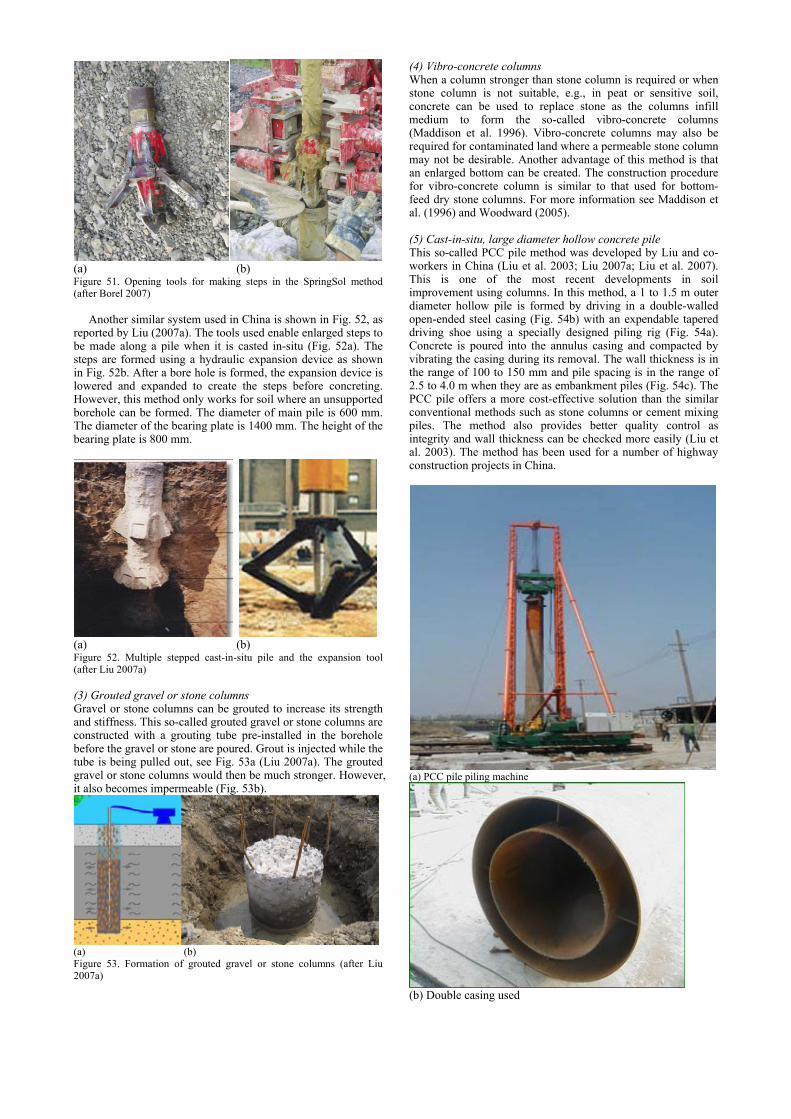
(a) (b) Figure 51. Opening tools for making steps in the SpringSol method (after Borel 2007)
Another similar system used in China is shown in Fig. 52, as
reported by Liu (2007a). The tools used enable enlarged steps to be made along a pile when it is casted in-situ (Fig. 52a). The steps are formed using a hydraulic expansion device as shown in Fig. 52b. After a bore hole is formed, the expansion device is lowered and expanded to create the steps before concreting. However, this method only works for soil where an unsupported borehole can be formed. The diameter of main pile is 600 mm. The diameter of the bearing plate is 1400 mm. The height of the bearing plate is 800 mm.
(a) (b) Figure 52. Multiple stepped cast-in-situ pile and the expansion tool (after Liu 2007a) (3) Grouted gravel or stone columns Gravel or stone columns can be grouted to increase its strength and stiffness. This so-called grouted gravel or stone columns are constructed with a grouting tube pre-installed in the borehole before the gravel or stone are poured. Grout is injected while the tube is being pulled out, see Fig. 53a (Liu 2007a). The grouted gravel or stone columns would then be much stronger. However, it also becomes impermeable (Fig. 53b).
(a) (b) Figure 53. Formation of grouted gravel or stone columns (after Liu 2007a)
(4) Vibro-concrete columns When a column stronger than stone column is required or when stone column is not suitable, e.g., in peat or sensitive soil, concrete can be used to replace stone as the columns infill medium to form the so-called vibro-concrete columns (Maddison et al. 1996). Vibro-concrete columns may also be required for contaminated land where a permeable stone column may not be desirable. Another advantage of this method is that an enlarged bottom can be created. The construction procedure for vibro-concrete column is similar to that used for bottom-feed dry stone columns. For more information see Maddison et al. (1996) and Woodward (2005). (5) Cast-in-situ, large diameter hollow concrete pile This so-called PCC pile method was developed by Liu and co-workers in China (Liu et al. 2003; Liu 2007a; Liu et al. 2007). This is one of the most recent developments in soil improvement using columns. In this method, a 1 to 1.5 m outer diameter hollow pile is formed by driving in a double-walled open-ended steel casing (Fig. 54b) with an expendable tapered driving shoe using a specially designed piling rig (Fig. 54a). Concrete is poured into the annulus casing and compacted by vibrating the casing during its removal. The wall thickness is in the range of 100 to 150 mm and pile spacing is in the range of 2.5 to 4.0 m when they are as embankment piles (Fig. 54c). The PCC pile offers a more cost-effective solution than the similar conventional methods such as stone columns or cement mixing piles. The method also provides better quality control as integrity and wall thickness can be checked more easily (Liu et al. 2003). The method has been used for a number of highway construction projects in China.
(a) PCC pile piling machine
(b) Double casing used

24
(c) PCC pile formed Figure 54. Cast-in-situ, large diameter concrete pile (after Liu et al. 2003) (6) Y-shaped or X-shaped cast-in-situ concrete pile This is another type of cast-in-situ pile. In forming the pile, a casing with an end plug as shown in Fig. 55 are driven into the ground before concrete is poured into the casing. With the use of three inversed circular sections, the Y-shaped pile saves concrete and yet can provide the same surface area and thus same amount of skin friction compared to the circular concrete pile of the same diameter. Usually the Y pile adopts the following geometries: the cross-section area is 0.157 m3 and the circumference of the pile is 2.124 m. At the top, a circular pile cap of 1.4 m in diameter is normally used (after Liu 2007a).
Another type of cast-in-situ pile is the so-called X-shaped pile developed by Liu et al. (2007b). The typical cross-section, the casing used to cast the pile and the pile tip are shown in Fig. 56.
(a) Cross-section of the casing (b) Casing used
(c) Concrete pile tip plug (d) Y-shaped pile formed Figure 55. Y-shaped cast-in-situ concrete pile (after Liu 2007a)
2.5.6 Geosynthetic-reinforced column/pile supported embankment (C6)
For road or rail constructions over soft ground, geosynthetic-reinforced columns/pile supported embankment, or the so-called piled embankment system, has often been used. In this system, piles or columns are used together with a load transfer platform to support embankment on soft soil as shown in Fig. 57 (Han et al. 2004; Collin et al. 2005). The piles can be either concrete piles, stone columns, CCG, or any types of the rigid inclusions discussed above.
(a) Cross-section of the pile (b) Cross-section of the casing
(c) Casing looking from the top (d) driving tip Figure 56. X-shaped cast-in-situ concrete pile (after Liu et al. 2007b)
Figure 57. A typical design of geosynthetic reinforced column supported embankment (after Collin et al. 2005)
The load transfer platform consists of single or multiple layers of geogrid placed horizontally in a layer of well compacted crushed stones or gravels. The platform has a typical thickness of 0.4 to 1 m depending on type of structure and soil conditions. Such a system has often been used for bridge approach as shown in Fig. 58. As an example, the construction of the load transfer platform is shown in Fig. 59. A constructed geosynthetic reinforced column supported embankment with the base eroded during a flooding is shown in Fig. 60 which indicates the effectiveness of the system.
Figure 58. Applications of deep cement mixing columns and PVDs for a bridge approach (after Lin and Wong 1999)

Figure 59. Use of geosynthetic reinforced pile supported embankment for bridge approach (courtesy H.L. Liu)
Figure 60. Effect of geosynthetic reinforced pile supported embankment (originated from Huesker)
Figure 61. Effect of biocementation: (a) formation of slime bonding; (b) cementation effect.
2.5.7 Microbial treatment (C7)
Although a relatively new idea, the use of microorganisms for soil improvement or the biological processes in geotechnical engineering in general has been identified as a “high priority” research area and cited as “a critical research thrust and the opportunity for the future” in a report by the National Research Council (NRC) of USA in 2006. The principle of microbial treatment is to use microorganisms to produce bonding and cementation in soil so as to increase the shear strength and reduce the permeability of soil or rock. To describe the two effects, biocementation and bioclogging have been used in the literature. A number of studies have been carried out in recent years (Mitchell and Santamarina 2005; DeJong et al. 2006; Ivanov and Chu 2008; Van der Ruyt and van der Zon 2009). One example is shown in Fig. 61 where iron reducing bacteria was used to produce slime bonding between sand grains to
enable a dry sand column to carry weight. A few patents have also been filed (e.g., Kucharski et al. 2005). However, there is little practical applications so far. It was reported by GeoDelft that a BioSealing technique was used for the first time for the Aquaduct Ringvaart Haarlemmermeer as a part of the high-speed rail link (http://www.smartsoils.nl//EN/page24.asp).
2.5.8 Other methods (C8)
(1) Sand pile formation by blasting A method of forming sand piles using hidden explosions with elongated blasting charges was also used in Europe (Dembicki et al. 2006). In adopting this method, an additional layer of sand fill is first placed on the soft soil to be treated. Elongated explosive charges are installed, blast and then backfill. A sand pile as shown in Fig. 62a is formed. The method has been used for the A1 motor way in Poland (Dembicki et al. 2006), as shown in Fig. 62b.
soft clayeydeposit
soft clayeydeposit
(a) Illustration of the mechanisms
(b) Application to A1 motorway in Poland Figure 62 Sand pile formation by blasting method (after Dembicki et al. 2006)
A similar method is also adopted in northwest part of China for installation of short cement mixing soil columns in clayey or silty soil or losses stratum with low water table for road or foundations of low-rise buildings. Elongated explosives are used to create boreholes of 350 to 600 mm. Cement mixed clay fill is then filled into the borehole in layers and compacted to form stiff columns (Zhu et al. 2003).

26
(2) Use of bamboo, timber and other natural products In countries where natural products such as bamboo and timber are abundant, it can be more economical to use these natural products for soil improvement. Some case histories have been presented by Rahardjo (2005) and Irsyam et al. (2008). The applications include slope repair and stabilization, as piles for embankment, and for road construction. An example for road construction on soft ground in Indonesia is shown in Fig. 63. Better effect may be achieved by plcing a horizontal geotextile layer.
Figure 63. Use of bamboo and timber for pile raft system for road construction in Indonesia (after Rahardjo 2005) 2.6 Ground improvement with grouting type admixtures
Grouting technology has become a common ground improvement method used frequently for underground and foundation constructions. The process of grouting consists of filling pores or cavities in soil or rock with a liquid form material to decrease the permeability and improve the shear strength by increasing the cohesion when it is set. Cement base grout mixes are commonly used for gravely layers or fissure rock treatment. But the suspension grain size may be too big to penetrate sand or silty-sand layers. In this case, chemical or organic grout mixes are also used. In recent years, the availability of ultrafine grout mixes has extended the performance of hydraulic base grout for soil treatment. Special types of grouting such as compensation grouting for settlement monitoring in tunnel ling projects and compaction grouting for ground improvement have also been developed. The process of grouting is regulated according to European Standard EN 12715 (2000) - Execution of Special Geotechnical Work – Grouting in Europe. A Grouting Technical Standard has been used in Japan which has been revised in 2003. There are also relevant ASTM standards such as ASTM C476 Standard
Specifications for Grout for Masonry (2008). Projects involving grouting may require specific attentions due to applicable health and safety regulations and restrictions introduced by Environmental protection program.
The grout mix can be generally classified into four types: (1) mortar and pastes such as cement to fill in holes or open cracks; (2) suspensions such as ultra-fine cement to seal and strengthen sand and joints; (3) solutions such as water glass (silicate) and (4) emulsions such as chemical grout (Semprich and Stadler 2005). The operational limits of different grout mix are dependent on the type of soils and the grain size distribution of the soil. The typical range for each grout mix is shown in Fig. 64. A simple classification of grouting methods according to grouting principles is given in BS-EN12715 (2000) and is reproduced here as Fig. 65. Another classification system for grouting is used by Semprich and Stadler (2005). Recent developments in grouting techniques and their applications have been covered extensively by Karol (2003), Warner (2004), Semprich and Stadler (2003). In this report, only some of the grouting methods are discussed.
Figure 64. Operational limits of different grout mix (after Semprich and Stadler 2003)
Figure 65. Classification of grouting methods by principles (after BS-EN12715 2000)
2.6.1 Particulate grouting (D1)
In the past, rock treatment was done by grouting with unstable cement suspensions which were increased step by step until pressure refusal criteria were met. Nowadays grouting is conducted with fully stable mixes which are composed of cement, bentonite and plasticizer with proportions according to required strength. For soil treatment, both cement suspension and sodium silicate gel (organic reagent for consolidation and mineral reagent for waterproofing) are used. By the 1990’s, the availability of ultrafine grout mixes has extended the performance of hydraulic base grout for soil treatment. A picture showing the use of ultrafine cement mix for sandy gravel is shown in Fig. 66.
The use of organic hard gel for soil consolidation was subsequently reconsidered to prevent unnecessary pollution of groundwater. However, sodium silicate grout is continuously used for temporary works or when adverse conditions are encountered.
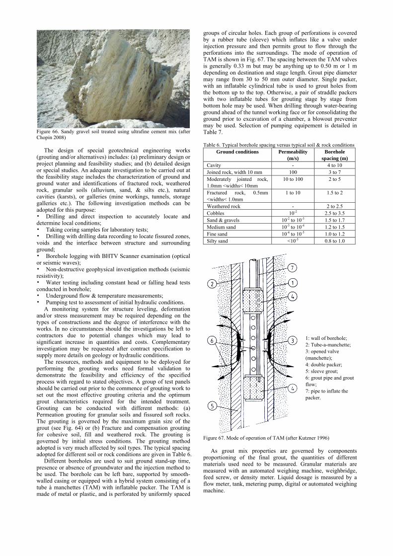
Figure 66. Sandy gravel soil treated using ultrafine cement mix (after Chopin 2008)
The design of special geotechnical engineering works (grouting and/or alternatives) includes: (a) preliminary design or project planning and feasibility studies; and (b) detailed design or special studies. An adequate investigation to be carried out at the feasibility stage includes the characterization of ground and ground water and identifications of fractured rock, weathered rock, granular soils (alluvium, sand, & silts etc.), natural cavities (karsts), or galleries (mine workings, tunnels, storage galleries etc.). The following investigation methods can be adopted for this purpose: • Drilling and direct inspection to accurately locate and determine local conditions; • Taking coring samples for laboratory tests; • Drilling with drilling data recording to locate fissured zones, voids and the interface between structure and surrounding ground; • Borehole logging with BHTV Scanner examination (optical or seismic waves); • Non-destructive geophysical investigation methods (seismic resistivity); • Water testing including constant head or falling head tests conducted in borehole; • Underground flow & temperature measurements; • Pumping test to assessment of initial hydraulic conditions.
A monitoring system for structure leveling, deformation and/or stress measurement may be required depending on the types of constructions and the degree of interference with the works. In no circumstances should the investigations be left to contractors due to potential changes which may lead to significant increase in quantities and costs. Complementary investigation may be requested after contract specification to supply more details on geology or hydraulic conditions.
The resources, methods and equipment to be deployed for performing the grouting works need formal validation to demonstrate the feasibility and efficiency of the specified process with regard to stated objectives. A group of test panels should be carried out prior to the commence of grouting work to set out the most effective grouting criteria and the optimum grout characteristics required for the intended treatment. Grouting can be conducted with different methods: (a) Permeation grouting for granular soils and fissured soft rocks. The grouting is governed by the maximum grain size of the grout (see Fig. 64) or (b) Fracture and compensation grouting for cohesive soil, fill and weathered rock. The grouting is governed by initial stress conditions. The grouting method adopted is very much affected by soil types. The typical spacing adopted for different soil or rock conditions are given in Table 6.
Different boreholes are used to suit ground stand-up time, presence or absence of groundwater and the injection method to be used. The borehole can be left bare, supported by smooth-walled casing or equipped with a hybrid system consisting of a tube à manchettes (TAM) with inflatable packer. The TAM is made of metal or plastic, and is perforated by uniformly spaced
groups of circular holes. Each group of perforations is covered by a rubber tube (sleeve) which inflates like a valve under injection pressure and then permits grout to flow through the perforations into the surroundings. The mode of operation of TAM is shown in Fig. 67. The spacing between the TAM valves is generally 0.33 m but may be anything up to 0.50 m or 1 m depending on destination and stage length. Grout pipe diameter may range from 30 to 50 mm outer diameter. Single packer, with an inflatable cylindrical tube is used to grout holes from the bottom up to the top. Otherwise, a pair of straddle packers with two inflatable tubes for grouting stage by stage from bottom hole may be used. When drilling through water-bearing ground ahead of the tunnel working face or for consolidating the ground prior to excavation of a chamber, a blowout preventer may be used. Selection of pumping equipement is detailed in Table 7. Table 6. Typical borehole spacing versus typical soil & rock conditions
Ground conditions Permeability (m/s)
Borehole spacing (m)
Cavity - 4 to 10 Joined rock, width 10 mm 100 3 to 7 Moderately jointed rock, 1.0mm <widths< 10mm
10 to 100 2 to 5
Fractured rock, 0.5mm <widths< 1.0mm
1 to 10 1.5 to 2
Weathered rock - 2 to 2.5 Cobbles 10-2 2.5 to 3.5 Sand & gravels 10-2 to 10-3 1.5 to 1.7 Medium sand 10-3 to 10-4 1.2 to 1.5 Fine sand 10-4 to 10-5 1.0 to 1.2 Silty sand <10-5 0.8 to 1.0
Figure 67. Mode of operation of TAM (after Kutzner 1996)
As grout mix properties are governed by components
proportioning of the final grout, the quantities of different materials used need to be measured. Granular materials are measured with an automated weighing machine, weighbridge, feed screw, or density meter. Liquid dosage is measured by a flow meter, tank, metering pump, digital or automated weighing machine.
1: wall of borehole; 2: Tube-a-manchette; 3: opened valve (manchette); 4: double packer; 5: sleeve grout; 6: grout pipe and grout flow; 7: pipe to inflate the packer.

28
Table 7. Pumping equipment Field of application Equipment
Low pressure grouting of cavities and void aerated foams and filled grouts
Centrifugal pumps delivering 1 to 100 m3/hr Screw pumps delivering 10 to 20 m3/hr Concrete type piston pumps delivering 10 to 50 m3/hr
Mortars with standard or fine-grained (<2 mm) fillers Cement grouts, gels or silicate grouts
Controlled flow injection equipment Mioneau types rotary or piston pump delivering 0.1 to 25 m3/hr under a pressure of 0.5 to 10 MPa
Injection of chemical grouts Injection of resins
Screw pump delivering 0.1 to 1 m3/hr Metering piston pump
Spraying or small quantities Hand gun or pressure pot Depending on the intrinsic properties of the host ground,
objectives of grouting and environmental considerations, the following parameters are normally used to set grouting criteria: grout volume per stage, grouting pressure, grout inflow, and the order of injection or sequencing.
The grout volume to be injected depends on ground porosity, geometry of the treated zone, grout hole spacing, stage length and total depth to be treated. The grouting pressure is defined as an effective value as it cannot be directly measured in the ground because of the head losses caused by the equipment. Pressures are measured and recorded at the borehole collar. The flow of grout through the injection plant is associated with head losses which must be deducted from the total pressure. The grouting pressure and flow rate for a given ground type and grouting details (such as the grout type and stage length) are mutually related. Common units used are m3/hr or litres/minute. The process of treatment can be set out accordingly with the following parameters: a) Recording of drilling parameters; b) Recording of grouting parameter; c) Hydro- and geo-mechanical test parameter recording; d) Data integration and processing; e) Grout hole pattern design; f) Analysis and specification of grouting criteria; g) Management and control of grouting criteria; and h) Displacement monitoring and grouting control.
The groutability of soil with particulate grouting has been evaluated based on the N value, (Mitchell and Katti 1981) where N is defined as N = (D15)Soil / (D65)Grout. Grouting is considered feasible if N > 24 and not feasible if N < 11. Another alternative is to use Nc = (D10)Soil / (D95)Grout. Grouting is considered feasible if Nc > 11 and not feasible if N < 6 (Karol 2003). Based on laboratory studies, a new N value has been proposed by Akbulut and Saglamer (2002) as:
rD
PkFC
cwkgroutdsoilD
N 2190
10)(
)(++= (3)
where w/c is the water cement ratio of the grout; FC is the total soil mass passing through 0.6 mm; P is the grouting pressure; Dr is the relative density of the soil; k1 and k2 are two constants. k1 = 0.5 and k2 = 0.01 1/kPa are suggested by Akbulut and Saglamer (2002) for the soil tested. The new equation can take other factors into consideration, such as the water cement ratio, grout pressure and relative density of the soil. Soil is considered groutable when N > 28 and not groutable when N < 28.
Fracture grouting consists of progressively consolidating ungroutable ground (silts or clay sands) to create a set of isolated fractures which will reduce seepage through the soil. Since the grouting is done with a grout that will not permeate the ground in question, the percentage treatment is of the order of 5% to 15% of the relevant soil volume. This must always be done in stages, for example, two or three times 5%.
Many case histories of particulate grouting have been reported in the literature (e.g., Littlejohn 2004a; Schmall et al. 2007). A field evaluation of three different permeation grouts, namely sodium silicate, microfine powder, and microfine
cement in a medium-dense, silty sand outwash deposit has been carried out by Brachman et al. (2004). It was found from this study that the sodium silicate grout zone was uniformly permeated and had a massive structure. The microfine powder grout appeared to permeate the outwash sand but did not harden in the ground. The specific formulation of the microfine cement grout resulted in only discrete veins of grouted sand. Cross-hole seismic velocity tests were conducted in this project. The average shear wave velocities measured through the grout zone were approximately 480 m/s in sodium silicate, 340 to 420 m/s in microfine cement or microfine powder. The shear wave velocity for the ungrouted sand was around 230 m/s (Brachman et al. 2004).
2.6.2 Chemical grouting (D2)
Chemical grouting is defined as any grouting material characterized by being a pure solution; no particles in suspension (Committee on Grouting 1980). In practice, suspended solids are often added to chemical grouts to modify the solution properties as additives. The types of chemical grouting materials have been classified into six categories by Karol (2003): Sodium silicate formulations; acrylics; lignosulfites-lignosulfonates; phenoplasts; aminoplasts; and other materials. The major difference between particulate grouts and chemical grouts is in the penetrability. Chemical grouts can penetrate into soil with finer particles as shown in Fig. 64. The penetrability for chemical grouts is a function of the solution viscosity whereas the penetrability for particulate grouts is a function of particle size. The penetrability of various grouts is shown in Fig. 68.
A comprehensive coverage of various topics on chemical grouting has been provided by Karol (2003). The properties of the chemically grouted soil mass can vary over a wide range for any single grout. Nevertheless, a comparison over a broad range is made by Karol (2003) as shown in Table 8.
Figure 68. Penetrability of various grouts (after Karol 2003)
Attempts to use electro-osmosis for the delivery of chemical
grouting have also been made (Thevanayagam and Rishindran 1998; Alshawabkeh and Sheahan 2002). This so-called electro-grouting method may also be used for site remediation.
A number of case histories of applications of chemical grouting have been given by Karol (2003) and Powers et al. (2007). Chemical grouting has been used for some major hydraulic or dam constructions in China including the Three Gorges Dam and other projects (Tao et al. 2006). Many studies have been carried out recently on the properties of grouted soil. However, there are relatively fewer case histories published. Examples include the use of chemical grouting for the repair of an underwater road tunnel in Montréal, Canada by Palardy et al. (2003) and a field trial of the use of colloidal silica grouting for mitigation of liquefaction (Gallagher et al. 2007).

Table 8. Relative ranking of solution grouts (after Karol 2003) Groups Grouts Corrosivity
or toxicity Viscosity Strength
Silicate Joosten process Siroc Silicate- bicarbonate
Low Medium Low
High Medium Medium
High Medium to high Low
Lignosulfates Terra Firma Blox-all High Medium Low
Phenoplasts Terranier Geoseal Medium Medium Low
Aminoplasts Herculox Cyanalog Medium Medium High
Acrylamides AV-100 Rocagel BT Nitto-SS
High Low Low
Polyacry- lamide Injectite 80 Low High Low Acrylate AC-400
Terragel Flexigel DuriGel
Low Low Low
Polyurethane CR-250 CR-260 TACSS CG5610 AV202
High High High
2.6.3 Mixing methods (D3)
Mixing soil with cement, lime or other binders has been a common soil stabilization method. For fills, the mixing can be done before placement with or without compactions. Most frequently, soils are mixed in-situ with cement and/or lime using a specially made machine. This method was developed in Japan and in the Scandinavian countries independently in the 1970s. The method has been called in different names, but commonly referred to as deep cement mixing (DCM or DMM). Various methods in the DCM are classified in Fig. 69. There are generally two installation methods, the dry mixing and wet mixing. As an example, the procedure for the formation of a DCM panel on-land is shown in Fig. 70.
Figure 69. Classification of the deep mixing method (after Essler and Kitazume 2008)
Comprehensive reviews and descriptions of the various methods of deep mixing and applications have been given by Terashi (2003), Topolnicki (2004), Larsson (2005), Essler and Kitazume (2008) and Arulrajah et al. (2009). Standards such as BS EN 14679 (2005) for deep mixing have been established. The recent developments have mainly taken place in the optimisation of the process and the optimisation of tools for mass production.
Figure 70. Procedure of the wet DCM method for on land work (after Essler and Kitazume 2008)
A new method called modified dry mixing (MDM) has been
developed in Sweden (Gunther et al. 2004). Without losing any sense of humour, this new method is characterised by adding approximately 20 litres of water per meter length of drilling by utilisation of a coaxial drilling Kelly. The construction process of this method is illustrated in Fig. 71. During installation, the dry binder is fed pneumatically. At the same time, water is added through separate injection ports on the mixing tool. The addition of water facilitates penetration of stiff soils, fluidises low plastic clays as well as ensures the complete hydration of the added binder (Gunther et al. 2004). In this way, the MDM method will be able to be used for a wider variety of soil than the dry mixing method and improve the difficulties usually encountered by insufficient water content, penetration of stiff crust or layer, heterogeneous soil layers, and reduce the air pressure. This method has been applied to various soils including very stiff clay and very dense and semi-dry sand (Eriksson et al. 2005). For soft soil, a case study of this method for a parking house in Sweden is also reported by Ericson et al. (2005). The cement mixing columns were installed in very soft clay with an undrained shear strength of 15 kPa using the MDM method. The strength of the column achieved was 2 to 5 MPa. Other applications in soft clay include Bergado and Lorenzo (2005) and Chai and Mivura (2005).
Figure 71. Modified dry mixing (MDM) method (after Gunther et al. 2004)
If the vacuum consolidation method provides an optimal
solution for very soft clay deposits and dredged slurry, a working platform on top of the soft clay layer is always required for the application of vacuum consolidation. The sand sprinkling method described in Section 2.4.8 is one of the methods to form this working platform. An alternative method is DCM. An application of the DCM method in conjunction with the vacuum consolidation method is reported by Burgos et al. (2007) for a container terminal. The site to be treated consisted of 14 m thick of extremely soft clay dredged in a losing dike. The soil improvement was carried out in two steps. The first was to treat the top 4 m of mud using the DCM method to form a soil-cement crust. As shown in Fig. 72, an original mixing tool was mounted on a hydraulic excavator. Once one section was improved, it provided a working platform for the other sections to be treated. The second step was to treat the deeper layer of soft soil using the conventional vertical drain

30
and surcharge method. The DCM treated platform enabled PVDs being installed and the surcharge fill being placed. The design specifications for the undrained shear strength of the cement treated soil were 75 kN/m² and the CPT cone resistance was 900 kN/m². The amount of cement added was in the range of 70 to 110 kg/m3. The laboratory tests on the cored samples showed a very wide scatter. Nevertheless, both the laboratory and CPT measurements exceeded largely the design criteria.
Figure 72. Use of deep cement mixing to form a working platform on top of muddy deposit (after Burgos et al. 2007)
Premixing soil cement method has also been used for some
large scale projects. One example is the trans-Tokyo Bay highway and railway bridge abutments (Tatsuoka 2004). Pre-mixed cement sand slurry or dry mix was used for the construction of offshore embankment. The use of underwater placed dry cement mixed sand for the Kisarazu man-made Island is shown in Fig. 73.
Figure 73(a) Placement of premixed cement sand
Figure 73(b). Use of underwater placed dry cement mixed sand for the Kisarazu man-made Island (after Tatsuoka 2004)
New construction tools and procedures have been developed in recent years to adapt to different construction requirements. Two innovative soil mixing methods: Geomex or CSM (cut soil mixing) wall and Trenchmix have been presented by Borel (2007). The Geomex or CSM method use a cutter as shown in Fig. 74 to form soil mixing panel such as diaphragm walls or cut-off walls. It provides a cost effective solution for the rapid construction of retaining and cut-off walls by mixing soil in situ with a cement / bentonite grout. The equipment for the CSM wall consists of cutting and mixing drums mounted on compact hydraulic motors. The drums are essentially designed to combine high penetration rates with excellent soil/ cement mixing. The precise positioning and verticality of the wall is achieved using a telescopic Kelly bar down to 30 m depth. For deeper walls, rope suspended equipment, with in-trench guidance mechanisms is recommended. The Trenchmix uses cutting tools as shown in Fig. 75 to excavate trenches for structural of permeability applications. It has a dry and a wet method. Fig. 75 shows the dry method. The Trenchmix method produces a soil mix barrier, up to a depth of 10 m, in a single continuous pass which is claimed to be more cost effective than the traditional methods.
Figure 74. Geomix CSM method for deep cement mixing (after Borel 2007)
Figure 75. Trenchmix method (after Borel 2007)

One major concern for the use of DMM method is quality control. To ensure sufficient quality of the stabilized column, quality control and quality assurance is required before, during and after construction. The design, construction and quality control procedure for DMM are shown in Fig. 76. For this purpose, quality control for DMM consists mainly of i) laboratory mixing tests, ii) quality control during construction and iii) post-construction quality verification through boring and column head inspection.
Figure 76. Example of a Flow chart for quality control and quality assurance for wet method (after Essler and Kitazume 2008)
2.6.4 Jet grouting (D4)
Jet grouting is a method involving drilling down with a small diameter rod system, typically 90-130mm in diameter and then injecting a high pressure fluid while rotating and withdrawing the rod to erode soil and replace or mix it with cement grout under a high pressure (~ 200 bars) to form a circular cement column of typically 1 to 1.6 m. The Jet grouting installation methods include single, double and triple methods with the triple tube being the most effective technique. As a semi- or complete replacement method, jet grouting in theory is applicable to all types of soil. Information on the practice of jet grouting has been posted in the TC17 website (Maertens 2008). Standards including BS EN12716 (2001) - Execution of Special Geotechnical Work –Jet Grouting have been established. Jet grouting has been increasingly used for very difficult ground conditions. Therefore, increasing efforts have been devoted to the controlling of the jet grouting process during and after execution. These include: 1) The use of inclinometers to determine the exact position of
the grout columns. Such measurements can be performed by means of an inclinometer installed underneath the monitor or by lowering an inclinometer through the central opening of the drilling rods;
2) The pressure in the fresh grout can be measured to control the evacuation of the grout. Over- or under pressures within the fresh grout can be measured by means of a total pressure cell with automatic registration installed just above the monitor. Grout pressures higher than the hydrostatic groundwater pressure can lead to a decrease in the column diameter (Maertens and De Vleeschauwer 2000). On the other hand, pressures lower than the hydrostatic groundwater pressure will also cause instabilities in the soil around the grout column and result in ground settlements;
3) Special devices have been developed to measure the diameter of a column. Considerable effort has been made in the past to increase the reliability of this types of measurement by improving the equipment and the calibration methods.
Another technique for jet grouting is the so-called Superjet grouting (Burke et al. 2000). Grout, air and drilling fluid are pumped through separate chambers in the drill string, as shown
in Fig. 77. Upon reaching the design drill depth, jet grouting is initiated with high velocity, coaxial air and grout slurry to erode and mix with the soil, while the pumping of drilling fluid is ceased. This system uses opposing nozzles and a highly sophisticated jetting monitor specifically designed for focus of the injection media. Using very slow rotation and lift, soilcrete column with diameters of 3-5 m can be achieved. This is the most effective system for mass stabilization application. Case studies on the application of this method have been given in Welsh and Burke (2000) and Burke et al. (2000).
Figure 77. Process of Superjet grouting (after Welsh and Burke 2000)
X-jet grouting is another technique. It is unique in that it
consists of a pair of intersecting air-shrouded water jets with separate grout jets as shown in Fig. 78. It is designed to cut a nominal 2 m diameter column in any ground.
Figure 78. X-jet grouting (after Welsh and Burke 2000)
Case histories of jet grouting are provided by Essler and Yoshida (2004), Page et al. (2006) and many others. In Singapore, jet grouting has often been used to install horizontal

32
supports for deep excavation in soft clay (Lim and Tan 2003, Wong and Poh 2005; Wen 2005; Shirlaw et al. 2006). As shown in Fig. 79 as an example, three jet grouting layers were used as struts to support the diaphragm walls during deep excavation. The top two layers were removed as excavation proceeded. A similar system was adopted for the Nicoll Highway project in Singapore in which a failure of diaphragm wall took place (Yong and Lee 2007).
Final excavation level
Sacrificial JGP slabs
Figure 79. Use of jet grouting for deep excavation in soft ground (after Wen 2005)
Inappropriate use of jet ground layers for deep excavation
may lead to failure. One such a case for a cut-and-cover tunneling project is reported by Lim and Tan (2003) and Shirlaw et al. (2006). The cross-section of the excavation and the soil profile are shown in Fig. 80. The depth of excavation was 13 m. Marine clay was present at about 9 m below the reclaimed fill and the thickness of the soft marine clay below the final excavation level was at least 24 m. A floating combined sheet pile cum soldier pile cofferdam with a jet grout layer at final excavation braced internally with 3 layers of struts was adopted for the construction of the tunnels. The length of the combined sheet pile/soldier pile wall was 15 m with a penetration depth of 3.5 m below the final excavation. The design thickness of the jet grout layer was 2.5 m. The jet grout layer was restrained against upheaval force by two rows of king posts made of steel H-piles. The failure took place during excavation for the forth level of strutting. The jet grout layer suffered a failure in bending along the centre of the excavation over a length of about 50 m. The failure of the jet grout layer was accompanied by the king posts punching upwards, effectively taking out the strutting system, and accompanied by an inward rotation of one wall of the excavation. A photograph taken after the failure is shown in Fig. 81(a). A schematic illustration as interpreted by Lim and Tan (2003) is given in Fig. 81(b). The cause of failure was considered a combination of a number of factors. One of the key factors leading to the failure was attributed to the high stockpile of earth spoil placed too close to the excavation. However, the stockpile has been placed there for quite some time. Therefore, the trigger was the excavation of the 4th layer. Other factors included the thickness of the jet grout layer was only 2.0 m instead of the designed 2.5
m, the ground below the stockpile of earth was removed by 1.5 m as required by the design (Fig. 80) and the king posts were not penetrated to the designed depth (Lim and Tan 2003; Shirlaw et al. 2006).
Figure 80. Use of jet grouting layer to support a deep excavation (after Lim and Tan 2003)
(a) Picture of the failure
(b) Interpretation of the failure Figure 81. Failure of the excavation supporting system shown in Fig. 80 (after Lim and Tan 2003)
For the reconstruction of the Nicoll highway station, jet
mechanical mixing (JMM) or the so-called RASJET method was adopted for deep excavation in soft Singapore marine clay (Osborne and Ng 2008). JMM is a combination of soil mixing and jet grouting that produces overlapping columns with an internal column of mixed soil by the auger and an external column created by a slurry jet into the in-situ soil. The JMM machine is shown in Fig. 82. The process of forming the

columns is similar to the method of forming jet grouting columns with the addition of dual and counter rotation mixing blades on the drill rod to ensure intensive soil mixing. To install a JMM column, the auger is first drilled to the base level of the JMM column with water injection, and withdrawn to the top level of the JMM column with mechanical mixing without any injection. It then descends with slurry injection and mechanical mixing to form the internal soil mixing column up to base level. After that, it ascends with jetting to form the external jet grouting perimeter.
Figure 82. Jet mechanical mixing (JMM) machine and the drilling rod and mixing blades (after Osborne and Ng 2008)
2.6.5 Compaction grouting (D5)
Compaction grout involves controlled injection of very stiff, mortar-like grout (with less than 25 mm slump), at high pressure, into discrete soil zones. The grout generally does not enter soil pores but remains in a homogenous mass that gives controlled displacement to compact loose soils, lift structures, or both. The main mechanism of compaction grouting is densification. The methods of compaction grouting can be grossly classified into two categories: downstage and upstage, as illustrated in Fig. 83. The upstage method is more commonly used and its procedure involves (a) pre-drill a borehole and insert compaction grout casing; (b) pump low slump compaction grout mix in stages and withdraw at controlled rate; and (c) withdraw casing as stages are completed. Compaction grouting is suitable for treating a wide range of loose granular soils and voided fill and thus has been used as a method for liquefaction mitigation, as discussed in more detail in Section 4. Other applications include void filling and remediating a damaged roadway embankment (Scherer and Gay 2000) and compensating for settlement above tunnels and below foundations and plugging solution features (Woodward 2005). The method has also been used to support deep excavation into soft ground for a case in Shanghai (Liu et al 2005). A few more examples are given by Welsh and Burke (2000).
Figure 83. Typical compaction grouting sequence (after Woodward 2005)
An alternative compaction grouting technique has also been proposed by Naudts and Van Impe (2000) in which geotextile bags are used. In adopting this method, regular sleeve pipes are installed to the required depth. Geotextile bags are strapped straddling all or some of the sleeves. The geotextile bags are inflated via a double packer with a balanced, stable, low viscosity cement based suspension grout with high resistance against pressure filtration. Several bags (on different pipes) are inflated at the same time. The inflation process is done in stages to allow the water to slowly (pressure) filtrate through the geotextile bags. During each grouting stage the pressure is systematically increased. The spacing between the grout pipes has to be such that the soils are subjected to vertical stresses in excess of those they will eventually be subjected to. The volume reduction of the surrounding soils under the grouting pressure, as well as the influence radius of the compaction grouting can be mathematically estimated with the method described by Naudts and Van Impe (2000). This in turn dictates the spacing between the grout pipes. For projects in which the densification of soil is the main issue, the alternative compaction grouting method can result in a more controlled and predictable compaction system.
2.6.6 Compensation grouting (D6)
The term “compensation grouting” refers to a special grout injection that is designated to protect structures from potential damage as a result of adjacent or underground excavation (Mair and Hight 1994). The principle is to inject a sufficient volume of grout into the ground to compensate for the soil movement caused by excavation so that the ground or building settlement is minimised. The grout can be delivered by fracture grouting, intrusion grouting or compaction grouting. Although the method has been used mainly for fine-grained soils, its applications in granular soils have also been reported (Bezuijen and van Tol 2007). The method offers a solution to problems where other grouting methods such as permeation or jet grouting are not possible. A review of the compensation grouting method was presented in Mair and Hight (1994). A comprehensive account of its historical development was given by Littlejohn (2003b) and more recently by Gens (2007).
A typical application of compensation grouting for tunnelling construction is schematically illustrated in Fig. 84. Many case histories, in particular, the underground constructions in London have been reported (Mair 1994, 2008; Mair and Hight 1994; Harris 2001). Recent case histories include the tunnel construction of the Madrid Metro (Sola et al. 2003), the construction of a new metro line in Barcelona as shown in Fig. 85 (Gens et al. 2006) and the Porto Light Metro System in Italy (Chiriotti et al. 2006).

34
Figure 84. Compensation grouting for tunnelling construction (after Kummerer 2003)
Figure 85. Plan view of compensation grouting performed at the Juan Valera road zone (after Gens et al. 2006)
There have been concerns whether compensation grouting
can be successfully used in soft clay. A trial was conducted in soft Singapore marine clay (Shirlaw et al. 1999). The grout used consisted of a mixture of cement, bentonite and silicate. These were prepared as two solutions: 140 l sodium silicate, 60 l water and 59.93 kg cement, 179.78 l water, 3 kg bentonite. This grout gave a flow consistency of 8.58 seconds, a gel time of 72 seconds, and a vane shear strength of 29 kPa after 1 hour. A cross-section of the trial is shown in Fig. 86. It was concluded from the trial that it is possible to create surface heave by injecting grout into the soft Singapore marine clay. However, the grouting generated large excess pore pressures. The dissipation of the pore pressures induced extra settlement which would defeat the purpose of compensation grouting. Thus the use of compensation grouting as a building protection measure within the Singapore marine clay was unlikely to be successful.
Figure 86. A trial of compensation grouting in soft marine clay in Singapore (after Shirlaw et al. 1999)
Gens (2007) has pointed out that compensation grouting can
be applied to other excavation problems. One case study has
been presented by Liu (2003) where compensation grouting has been used to mitigate settlements in the case of a braced excavation in Shanghai clay. As shown in Fig. 87, compaction grouting was used for such a purpose.
Figure 87. Compensation grouting performed adjacent to a braced excavation (after Liu 2003)
An essential component of the implementation of
compensation grouting is the monitoring system. For a successful deployment, Littlejohn (2003b) suggested the following measures to be taken: i) to allow for a proper bedding-in period before movements are generated, ii) to incorporate a degree of instrument redundancy (including a manual backup system), iii) the use of dummy instruments for checking, and iv) the implementation of a proper interpretation and evaluation procedure that, in the case of compensation grouting must be operational in real time. Recently, the widespread use of automatic theodolite systems for surface and structure displacement monitoring has meant a significant advance in the availability of a large number of instrumented points that can be read with any desired frequency. However, this increased availability should not be detrimental to the number of instruments placed inside the ground, the only ones that can elucidate the mechanism of settlement generation and propagation. 2.7 Earth reinforcement
2.7.1 Geosynthetics or mechanically stabilised earth (MSE) (E1)
Initiated by Vidal in the beginning of the 60’s, soil reinforcement techniques in fills have gained increasing recognition over the last 30 years. Surprisingly, there has been no real conceptual breakthrough in the past in principles, key components and potential applications other than what has been described by Henri Vidal. Nevertheless, modern technologies combined with numerous analytical and experimental studies have advanced this technique to be one of the major innovations in civil engineering in the second half of the 20th century (Giroud 1986; Jones 1996; Jewell 1996; Koerner 1998). Design codes and standards have also been introduced. These include the BS 8006 (1995): Code of practice for strengthened/reinforced soils and other fills; European Standard EN 14475 (2006): Execution of special geotechnical works-Reinforced Fills; EN 13250 (2001) Geotextiles and geotextile-related products - Characteristics required for use in the construction of railways; as well as three other European standards on geosyntietic barriers for different purposes, EN 13361, EN13491, and EN13492. The earth reinforcement has also become a highly attractive alternative for retaining wall projects as well as for steepened slopes due to its benefits in terms of reliability, flexibility, cost effectiveness and aesthetics.
A description of the different techniques involved in earth reinforcement in fill has been given in the TC17 website. Fill reinforcements can be made from metals (mainly steel), polymeric materials, natural fibre and recently fibre glass and carbon fibre. The types of reinforcement include: steel strips

(smooth and ribbed), steel ladder strips, steel welded wire grids/bar mats, steel bars/rods, woven wire mesh, geostrips (polymeric), geotextiles sheets (polymeric), geogrids and woven meshes (polymeric), and micro reinforcing elements (fibres, yarns, glass, microgrids). The facing types include segmental precast concrete panels, full height precast concrete panels, concrete sloping panels, concrete planters units, segmental concrete blocks, king post system, semi elliptical steel face, steel welded wire grid, geosynthetic (geogrid or geotextile)
wrapped around, woven wire mesh wrapped around, and gabion baskets. The main categories of reinforced fill applications with the relevant types of facings and reinforcements used are presented in Table 9.
Some examples of the facing types mentioned in Table 9 are given in Fig. 88. Practical applications of some of these facings in retaining wall and slope stability will be given in Section 4. For geosynthetic (geogrid or geotextile) wrapped around slope, the common configurations are shown in Fig. 89.
Table 9. Categories of reinforced fill applications (after WG-F, TC17 in www.bbri.be/go/tc17)
Mechanically stabilized earth: Earth retaining structures -Vertical -Battered -Inclined
Reinforcement types Steel strips (smooth and ribbed); Steel ladder strips; Steel welded wire grids / bar mats; Steel bars/ rods; Woven wire mesh; Geostrips (polymeric); Geotextiles sheets (polymeric); and Geogrids and woven meshes (polymeric).
Facing types
Segmental precast concrete panels; Full height precast concrete panels; Concrete sloping panels; Concrete planter units; Segmental concrete blocks; King post system; Metallic steel sheet; Semi elliptical steel face; Steel welded wire grids; Geosynthetics (geogrids or geotextiles) wrapped around (with formwork); Woven wire mesh wrapped around (with formwork); Gabion baskets; Post construction facing-2 stage system.
Specific applications Retaining walls - permanent and temporary; Pile supported abutments; True abutments; Mine slot walls for bulk storage; Dams; Containment structures; Specific structures.
Mechanically stabilized earth: Reinforced steep slopes with 45° < slope angle < 75 °
Reinforcement types Steel strips (smooth and ribbed); Steel ladder strips; Steel welded wire grids / bar mats; Steel bars/ rods; Woven wire mesh; Geostrips (polymeric); Geotextiles sheets (polymeric); Geogrids and woven meshes (polymeric).
Facing types Steel welded wire grids; Geosynthetics (geogrids or geotextiles) wrapped around (with formwork); Woven wire mesh wrapped around (with formwork); Gabion baskets.
Specific applications Steepened slopes; Containment structures;Reinforced shallow slopes with slope angle < 45° Reinforcement types
Steel strips (smooth and ribbed); Steel ladder strips; Steel welded wire grids / bar mats; Steel bars/ rods; Woven wire mesh; Geostrips (polymeric); Geotextiles sheets (polymeric); Geogrids and woven meshes (polymeric); Micro reinforcing elements (fibres, yarns, glass, micro grids).
Facing types Vegetated alone; Armoured (gabions, shotcrete, stone, emulsified asphalt); Geosynthetics (geogrids or geotextiles) wrapped around (without formwork); Woven wire mesh wrapped around (without formwork).
Specific applications Earth embankments with limited right of way; Slope repair. Base stabilization Reinforcement types
Steel strips (smooth and ribbed); Steel ladder strips; Steel welded wire grids / bar mats; Steel bars/ rods; Woven wire mesh; Geostrips (polymeric); Geotextiles sheets (polymeric); Geogrids and woven meshes (polymeric).
Specific applications Basal reinforcement; Replacement alternative to other ground improvement.
(a) Segmental precast concrete panels
(b) Concrete sloping panels (c) Concrete planters units
(d) Segmental concrete blocks
(e) Semi-elliptical steel face (f) Steel welded wire grid
(g) Gabion baskets Figure 88. Examples of the facing types mentioned in Table 9 (after WG-F, TC17 in www.bbri.be/go/tc17)
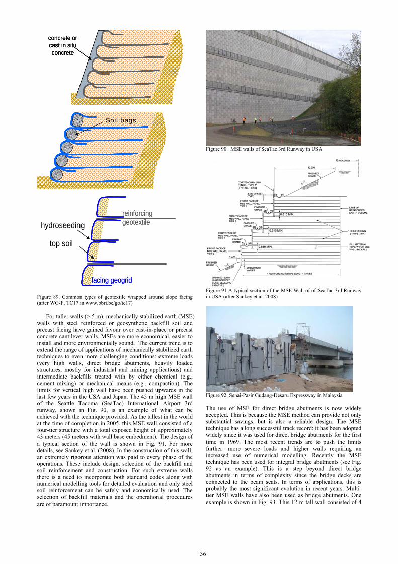
36
concrete or cast in situ concrete
concrete or cast in situ concrete
concrete or cast in situ concrete
Soil bagsSoil bags
Figure 89. Common types of geotextile wrapped around slope facing (after WG-F, TC17 in www.bbri.be/go/tc17)
For taller walls (> 5 m), mechanically stabilized earth (MSE) walls with steel reinforced or geosynthetic backfill soil and precast facing have gained favour over cast-in-place or precast concrete cantilever walls. MSEs are more economical, easier to install and more environmentally sound. The current trend is to extend the range of applications of mechanically stabilized earth techniques to even more challenging conditions: extreme loads (very high walls, direct bridge abutments, heavily loaded structures, mostly for industrial and mining applications) and intermediate backfills treated with by either chemical (e.g., cement mixing) or mechanical means (e.g., compaction). The limits for vertical high wall have been pushed upwards in the last few years in the USA and Japan. The 45 m high MSE wall of the Seattle Tacoma (SeaTac) International Airport 3rd runway, shown in Fig. 90, is an example of what can be achieved with the technique provided. As the tallest in the world at the time of completion in 2005, this MSE wall consisted of a four-tier structure with a total exposed height of approximately 43 meters (45 meters with wall base embedment). The design of a typical section of the wall is shown in Fig. 91. For more details, see Sankey et al. (2008). In the construction of this wall, an extremely rigorous attention was paid to every phase of the operations. These include design, selection of the backfill and soil reinforcement and construction. For such extreme walls there is a need to incorporate both standard codes along with numerical modelling tools for detailed evaluation and only steel soil reinforcement can be safely and economically used. The selection of backfill materials and the operational procedures are of paramount importance.
Figure 90. MSE walls of SeaTac 3rd Runway in USA
Figure 91 A typical section of the MSE Wall of of SeaTac 3rd Runway in USA (after Sankey et al. 2008)
Figure 92. Senai-Pasir Gudang-Desaru Expressway in Malaysia The use of MSE for direct bridge abutments is now widely accepted. This is because the MSE method can provide not only substantial savings, but is also a reliable design. The MSE technique has a long successful track record: it has been adopted widely since it was used for direct bridge abutments for the first time in 1969. The most recent trends are to push the limits further: more severe loads and higher walls requiring an increased use of numerical modelling. Recently the MSE technique has been used for integral bridge abutments (see Fig. 92 as an example). This is a step beyond direct bridge abutments in terms of complexity since the bridge decks are connected to the beam seats. In terms of applications, this is probably the most significant evolution in recent years. Multi-tier MSE walls have also been used as bridge abutments. One example is shown in Fig. 93. This 12 m tall wall consisted of 4
reinforcinggeotextile
facing geogrid
reinforcinggeotextile
facing geogrid
top soil
hydroseeding

tier modular block walls reinforced using high density polyethylene (HDPE) geogrids as soil reinforcements (Lo 2005).
Figure 93. Multi-tier modular block wall in Australia (after Lo 2005)
The use of intermediate backfill materials is a recent trend
due to the global concern about sustainable development. Good backfills are increasingly more difficult to find and the transportation of construction materials has a high environmental cost. The development of new construction materials, mostly polymeric, has opened a new and wide field for developments and realizations.
The experiences with steepened slopes or embankments are also relatively satisfactory although the durability of some backfill/reinforcement systems is still debatable. There is still much to be studied, both on the fundamentals of the technique and on the technology, for vertical and sub-vertical walls which is generally defined as structures with less than 20° of batter.
On the technological aspects, the challenge is to develop systems which offer adequate flexibility, including the connection between the facing and the reinforcement, while minimizing the deformations which are detrimental to the quality of the structures. With this respect, recent solutions based on the use of geostrips of relatively low extensibility associated with adequate proper synthetic connections seem to provide the right answer to the more environmentally and technically demanding projects.
2.7.2 Ground anchors or soil nails (E2)
Ground anchors are applicable to situations where gravity structures may be replaced by tying back with tensile members into soil or rock. It can also be used to counter buoyancy or uplift effect on structures or foundations and for stabilization of slopes, towers, tunnels and other structures. Some typical applications are illustrated in Fig. 94. The details can be referred to Ostermayer and Barley (2003) and De Cock (2008). Standards and design codes have been developed for the design and construction of ground anchors. These include the British Standard BS8081 (1989) and the European Standard EN1537 (1999).
Figure 94. Various applications of ground anchors (after De Cock 2008)
Depending on whether the anchors are used as temporary or permanent, different designs are applied, as shown in Fig. 95 as examples. The temporary anchor shown in Fig. 95a is a bond and tension type in which the load is transferred from the tendon to the bond (the grout). The permanent anchor in Fig. 95b is a tendon compression type in which the load is transferred by means of a steel tube connected to the rear of the tendon.
(a)
(b) Figure 95. Example of (a) a temporary anchor and (b) a permanent anchor (after Ostermayer and Barley 2003)
Soil nailing is similar to ground anchors or tiebacks in that a
steel rod is grouted into a pre-drilled hole. There are, however, several important differences. Nails are considerably smaller and shorter than anchors, and while anchors are pre-stressed after placement, nails are not (with few exceptions in which a very small pre-stress is applied), and do not pick up load until the soil mass deforms. Nails, like anchors, add shear resistance to the soil mass. In some instances augers have been drilled into place, avoiding the problem of caving drill holes. Recent experiments have indicated that the effectiveness of a nail is directly related to its pull-out resistance. Therefore augers, while more costly than plain or deformed steel bars, are also more effective. Currently, the major use of nailing is to stabilize man-made slopes, which occur as excavation proceeds for belowground structures. Typically, soil nailing is done as the excavation progresses. Wire mesh is placed on the exposed soil face and shotcrete is applied. Nail holes are then drilled to form a square grid with four or five foot spacing. The holes slant downward, up to 20o from the horizontal. Nail lengths are designed to extend beyond the possible failure plane for unreinforced soil, usually 75 to 100% of the slope height. Reinforce bars are placed in the holes, kept centered by plastic spacers. The final step is to grout the annulus with good quality cement.
Reviews of the applications of ground anchors and soil nails have been made by Sabatini et al. (1999), Barley and Windsor (2000), Ostermayer and Barley (2003) and De Cock (2008). A classification system has also been suggested by Cock (2008) as shown in Table 10. Some installation procedures are also discussed by De Cock (2008).

38
Table 10 Ground Anchor classification system proposed by De Cock (2008)
Ground anchors or nails have often been used for deep
excavation and retaining walls. Two examples of an excavation project in Singapore are shown in Fig. 96. More applications will be illustrated in Sections 3.1. When anchors are installed in granular soils, it may be used together with micropiles. One example is given by Schwarz et al. (2004). As shown in Fig. 97a, ground anchors are used to stabilise a sheetpile wall for a pier in Germany. Installation of anchors at waterfront is not easy. In this project, a travelling cradle as shown in Fig. 97b was used which could be moved on the quay wall (Schwarz et al. 2004). Other applications of ground anchor are also reported (e.g., Pinto and Barradas 2008). Examples of application of ground anchors or nails for slope stabilisation are presented in Section 4.3.3. In recent years, suction anchor as a new technique, has been used increasingly for the anchoring of offshore floating and fixed structures (Andersen et al. 2005).
Figure 96. Use of ground anchors or nails for deep excavation in Singapore
(a)
(b) Figure 97. Use of ground anchors together with micropiles in sand in Germany (a) Illustration; (b) Installation (after Schwarz et al. 2004)
2.7.3 Biological methods using vegetations (E3)
The roots provided by vegetation can be a type of reinforcement to slopes and retaining walls. Furthermore, it removes the soil water and even creates suctions in soil. It also helps in the prevention of ground erosion. Much of this topic has been covered by Gray and Leiser (1982), Gray and Sotir (1996) and Schiechtl (2003). Some examples will be given in Section 4.4.3. 2.8 Concluding remarks
Ground improvement is a diversified topic. It would not be possible to cover every aspect. It is also a fast growing subject. Its state-of-the-art is evolving all the time. Ground improvement is a practical driven discipline. It is not the method but the end result that matters. This poses challenges, but also gives opportunities for innovation. In conclusion, we would like to quote Mitchell and Jardine (2002) “It is the nature of many ground treatment techniques that their capability is continually being extended, overcoming what were previously seen as limitations. Moreover, different techniques can be combined to cope with a greater range of situations than one method on its own.”

3. UNDERGROUND CONSTRUCTIONS
3.1 Deep excavation
In recent years the number of deep excavation projects has increased all over the world especially in densely populated urban regions due to the demand for more infrastructures and the increase in land prices. Many deep excavation projects are carried out adjacent to historic and damageable buildings. This has complicated the design and construction of earth retaining walls. It has also become a common practice to define limit values e. g., for the lateral wall deflections or soil settlements beneath the building pit, in order to avoid damages of the nearby buildings. However, so far the prediction of those deflections and settlements is associated with many uncertainties. Therefore effective mitigation measures and monitoring of the construction process become essential for deep excavations (Fenelli and Ramondini 1997; Triantafyllidis et al. 1997; Addenbroke et al. 2000; Yoo 2001; Finno et al. 2005; Durgunoglu et al. 2007; Horodecki and Dembicki 2007; and Saglamar et al. 2007). Various retaining systems and construction methods have been developed to cope with different design and construction requirements. In the following, the different types of retaining systems and construction methods are briefly described and illustrated with case histories to provide an overview of the current state of the art of deep excavations. The corresponding managing risks and mitigation measures are summarized in a later section.
3.1.1 Retaining systems
There are a lot of different retaining systems that can be categorised according to their characteristics as for example the material, the structural system, the construction method or the utilization (Nussbaumer and v. Wolffersdorff 1997). In this report, the retaining systems are classified into soldier pile
walls, sheet pile walls, bored pile walls, diaphragm walls as well as composite structures and soil nailed walls. The principle of each type is summarized in Table 11 and in the subsequent sections. A more detailed classification can be found in Stocker and Walz (2003).
(1) Soldier pile walls If no water tightness of the retaining wall is required, soldier pile walls are often a competitive solution. Its original form, called “Berlin-type wall” or “Berlin method wall”, consists of H-sections with wooden planks wedged in between. The vertical posts are usually placed with distances between 1 m and 3 m. In order to avoid noise and vibrations it can be advantageous to drill holes and put the beams into them without driving. Meanwhile there are many variations for the infill walling as for example timber lagging, reinforced/unreinforced shotcrete or Mixed-In-Place piles. The latter have to be accomplished prior to the excavation (Weissenbach et al. 2003).
Case history: The construction of the new railway for Cologne-Rhine/Main in Germany is introduced. A 1.3 km long section of the excavation pit was achieved with soldier pile walls (see Fig. 98). The excavation depth ranged from 10 up to 15 m and the width of the pit was approximately 17 m. The low priced and quick achievable solution was feasible, because a watertight wall was not required due to the low permeability of the tertiary clay. Steel struts were designed as bracing system to avoid expensive and risky anchors inside of the clay layer. In order to reduce the static loading and the embedment depth of the driven steel beams movable struts were temporary placed a few metres above the planned excavation floor and removed after the installation of the current slab section. As a result the construction of the structure could be achieved with sufficient space between the first strut layer and the bottom. A total of four movable struts were used in cycles – each of them able to brace three king posts at both walls (Sänger 2000).
Table 11. Retaining systems
Category Principle
Soldier pile walls Berlin method wall Steel beams are driven into the soil or put into previously built boreholes. The spacing between the piles is filled with timber lagging, which is applied corresponding to the progress of the excavation.
Variants Instead of timber lagging, shotcrete can be used, e. g. if permanent structures will be casted against the infill and the rotting of timber laggings should be avoided.
Bored pile walls Soldier pile wall (King pile wall)
Only statically required piles are achieved and the spacings between the piles are filled with shotcrete or other infills.
Contiguous bored pile wall
Placement of the piles with contiguous pile sections to avoid infills between the piles
Secant bored pile wall Construction of the piles with overlapping sections in order to achieve a watertight wall. Usually only every second or third pile is reinforced and the other piles work mainly as infill.
Sheet pile walls Steel sheets with z- or u-sections are driven into the soil and connected with locks. To reduce noise and vibrations the sheets can also be put into a previously built and slurry-filled trench.
Diaphragm walls A trench is excavated by a grab, cutter or chisel and at the same time filled with slurry. After the excavation of a wall section and application of the stop-end panels the reinforcement cage is placed into the trench and the wall panel can be casted.
Soil nailed walls Step-by-step excavation and corresponding application of shotcrete on the soil surface. The nails are installed by driving, boring, vibration or rinsing and consist of steel or synthetic materials.
Composite structures Composite structures are built by combining different types of geotechnical elements, e. g. combinations of watertight and statical elements in order to achieve a wall with both properties.
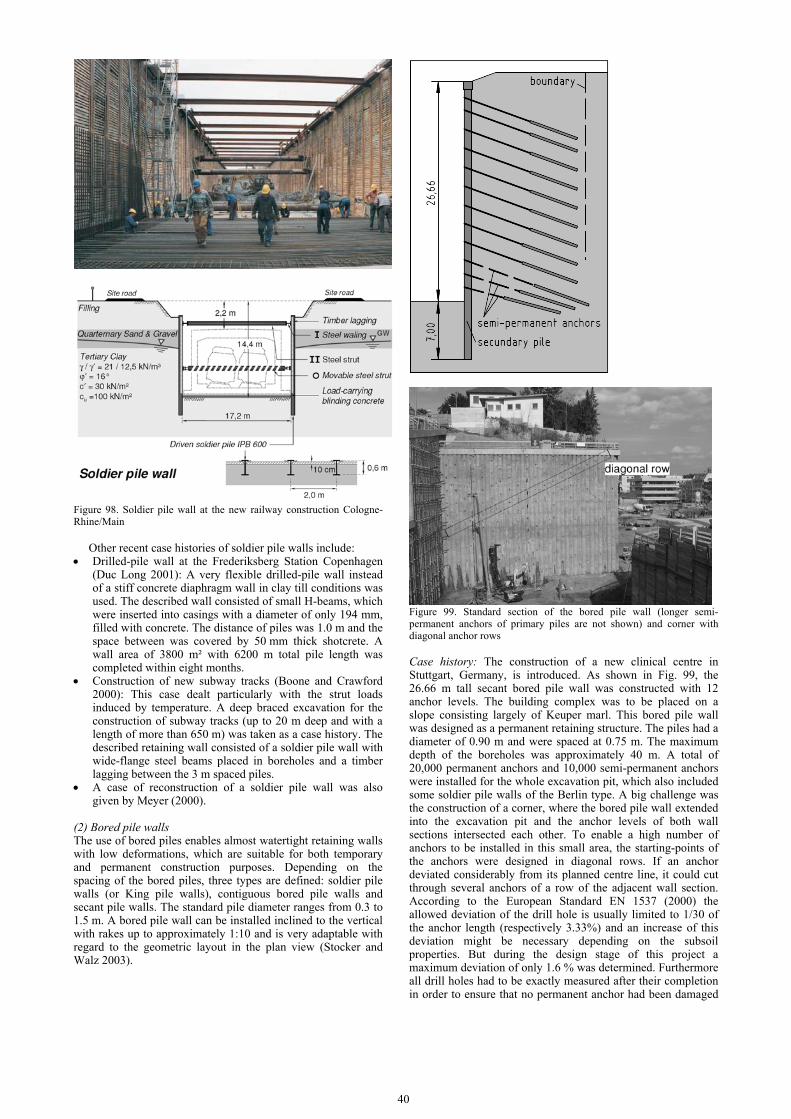
40
Figure 98. Soldier pile wall at the new railway construction Cologne-Rhine/Main
Other recent case histories of soldier pile walls include:
• Drilled-pile wall at the Frederiksberg Station Copenhagen (Duc Long 2001): A very flexible drilled-pile wall instead of a stiff concrete diaphragm wall in clay till conditions was used. The described wall consisted of small H-beams, which were inserted into casings with a diameter of only 194 mm, filled with concrete. The distance of piles was 1.0 m and the space between was covered by 50 mm thick shotcrete. A wall area of 3800 m² with 6200 m total pile length was completed within eight months.
• Construction of new subway tracks (Boone and Crawford 2000): This case dealt particularly with the strut loads induced by temperature. A deep braced excavation for the construction of subway tracks (up to 20 m deep and with a length of more than 650 m) was taken as a case history. The described retaining wall consisted of a soldier pile wall with wide-flange steel beams placed in boreholes and a timber lagging between the 3 m spaced piles.
• A case of reconstruction of a soldier pile wall was also given by Meyer (2000).
(2) Bored pile walls The use of bored piles enables almost watertight retaining walls with low deformations, which are suitable for both temporary and permanent construction purposes. Depending on the spacing of the bored piles, three types are defined: soldier pile walls (or King pile walls), contiguous bored pile walls and secant pile walls. The standard pile diameter ranges from 0.3 to 1.5 m. A bored pile wall can be installed inclined to the vertical with rakes up to approximately 1:10 and is very adaptable with regard to the geometric layout in the plan view (Stocker and Walz 2003).
Figure 99. Standard section of the bored pile wall (longer semi-permanent anchors of primary piles are not shown) and corner with diagonal anchor rows Case history: The construction of a new clinical centre in Stuttgart, Germany, is introduced. As shown in Fig. 99, the 26.66 m tall secant bored pile wall was constructed with 12 anchor levels. The building complex was to be placed on a slope consisting largely of Keuper marl. This bored pile wall was designed as a permanent retaining structure. The piles had a diameter of 0.90 m and were spaced at 0.75 m. The maximum depth of the boreholes was approximately 40 m. A total of 20,000 permanent anchors and 10,000 semi-permanent anchors were installed for the whole excavation pit, which also included some soldier pile walls of the Berlin type. A big challenge was the construction of a corner, where the bored pile wall extended into the excavation pit and the anchor levels of both wall sections intersected each other. To enable a high number of anchors to be installed in this small area, the starting-points of the anchors were designed in diagonal rows. If an anchor deviated considerably from its planned centre line, it could cut through several anchors of a row of the adjacent wall section. According to the European Standard EN 1537 (2000) the allowed deviation of the drill hole is usually limited to 1/30 of the anchor length (respectively 3.33%) and an increase of this deviation might be necessary depending on the subsoil properties. But during the design stage of this project a maximum deviation of only 1.6 % was determined. Furthermore all drill holes had to be exactly measured after their completion in order to ensure that no permanent anchor had been damaged

by another anchor. The measuring results were handed out to the scheduler and integrated into a three-dimensional computer-model. The measured data showed that no anchor had been damaged.
Other case histories of bored pile walls include: • Sotto Mayor Palace in Lisbon, Portugal (Pinto et al. 2001):
A bored pile wall was used as earth retaining and underpinning solution to protect the historic building of Sotto Mayor Palace against potential displacements due to a surrounding excavation. The whole foundation and the subjacent subsoil of the building were surrounded by contiguous bored piles with a diameter of 0.8 m, spaced at 1.0 m, see Fig. 100. The rectangular wall geometry enabled circumferential wall bracings consisting of 3 m high pre-stressed concrete ring beams.
Figure 100. Sotto Mayor Palace in Lisbon (according to Pinto et al. 2001)
• MOM-Center in Budapest, Hungary (Szepeházi et al. 2000
and 2001): The article deals with a combination of an anchored pile wall (CFA piles with shotcrete between) and a steep slope nailed in a heavy overconsolidated clay.
• Central Library of Libson, Portugal (Pinto et al. 2007): For the construction of 11 underground floors a 40 m deep excavation was achieved with a bored pile wall (main wall: 1.0 m pile diameter, 1.3 m spacing, 10 levels of permanent anchors).
• “FrankfurtHochVier” in Frankfurt am Main, Germany (Janke et al. 2006)
• A large and deep excavation in Ankara (Ufuk Ergun 2007) • Open deep excavation in Bucharest, Romania (Radulescu et
al. 2007)
(3) Sheet pile walls Sheet pile walls are almost impermeable but not as adaptable as compared with soldier pile walls. Due to their high bending resistance sheet piles are able to bridge large spans. In view of the construction process, U-shaped piles are often preferred, as they have a better driving capacity. The choice of a suitable profile not only depends on the static and driving capacity but also on the possibility of recovery and reusability. For deep excavations, sheet pile walls are rather expensive and therefore it is common to recover the sheet piling after completion of the building. In urban sites sheet piles are often put into slurry trenches to avoid noise and vibration (Weissenbach et al. 2003; Kuntsche 2007).
Case histories of sheet pile walls include: • Deep excavation in Konstanz, Germany (Krieg et al. 2004):
A large excavation pit comprised by a sheet pile wall in soft clay is described. In order to avoid the use of anchors inside of the clay the excavation process was achieved by means
of several segmental excavation pits. A sophisticated construction sequence with an adapted subdivision of the excavation area and placement of berms enabled the omission of anchors.
• Third Harbor Tunnel in Boston, USA: Tied-back sheet pile walls in soft clay (Cacoilo et al., 1998 and 2001): The poor presumed working capacity of the anchors (inside the Boston Blue Clay) was increased by special drilling procedures and post-grouting from 420 kN up to 770 kN and confirmed by a test program.
(4) Diaphragm walls Diaphragm walls are a very stiff and almost watertight type of retaining walls with common wall thicknesses between 0.4 m and 1.5 m. By the use of diaphragm wall cutters even a thickness up to 3.0 m can be achieved. At present maximum excavation depths of 100 m to 150 m are feasible. Under favourable site conditions and with proper care the tolerance of the vertical alignment can be kept below 0.5 %. The maximum horizontal wall movements can be limited to 0.1 to 0.2% of the free wall height by the application of tieback anchors. Diaphragm walls are a very expensive wall type but they also enable savings of space and time due to the facts, that they can be constructed directly in front of existing buildings without a gap and they can be used for the top/down construction method (Stocker and Walz 2003). Case history: Recently a new railway line was constructed in the province of South Holland, The Netherlands, which connects the city centres of Rotterdam, Den Haag and Zoetermeer. The cut and cover pit for the construction of the Blijdorp station at Rotterdam and the diaphragm walls used are shown in Fig. 101. The formation at the site was subdivided into 4 sub-horizontal layers: The top layer was anthropogenic fill which generally consisted of sand and has a thickness between 4.5 and 6.0 m in the area of the station. This soil layer was placed roughly 80 years ago to create a constructible underground. This fill layer was underlain by layers of peat and clay (“Westland Formatie”) from the Holocene which extended to depths beyond 15.0 to 18.0 m NAP (Normaal Amsterdams Peil). Below the Holocene formation were the Pleistocene formations “Formatie van Kreftenheye” and the “Formatie van Kedichem”. The former was a sand layer with a thickness about 19.0 m. The latter was made up of sand, peat, clay and loam layers.
As shown in Fig. 101, the excavation pit has a length of 126 m, an inner width of 22.8 m and a depth of 22 m below the ground level. The diaphragm wall panels have a depth of 41.0 m and are footed below the sand layer inside of the impermeable layer of Kedichem. Therefore no artificial sealing bottom was necessary. In order to stabilize the excavation pit, four sets of struts are placed at different depths. A fifth set of struts was installed in a depth of 8.75 m during dismantling the earlier placed struts.
In some parts of the pit, where the adjacent buildings were only 7.2 m away from the diaphragm wall, the client applied 1.5 m thick wall panels instead of 1.2 m in order to reduce the bending of the retaining walls and the influence on the adjacent foundations. In this part, the panel length was restricted to 3.0 m. Furthermore the structural analysis of the trench stability was carried out according to the German Standard DIN 4126 with an increased safety factor of 1.5 instead of 1.3. For the rest of the retaining walls, a panel length of 8.0 m and a safety factor of 1.3 were allowed. As a result of the safety factors L-shaped guide walls that were used for the trench excavation had to reach 1 m above ground level.
The joints between the adjacent diaphragm wall panels were provided by recoverable steel elements with trapezoid form, as shown in Fig. 102. Before the installation of the reinforcement cages, these joint elements were inserted into the open trench and hang up on the leading walls. Following the casting of the

42
primary panel and the excavation of the secondary panel the steel joint elements were detached from the concrete and lifted out of the trench. After cleaning the steel element it was used again for the following panels. This technique has been used first time on panels with such a depth and width. In order to improve the water-tightness, the steel joint elements were provided with rubber waterproof sealing strips (Fig. 102). These strips stayed inside of the concrete while the steel joint element was detached from the primary panel.
Figure 101. Excavation pit: Station Blijdorp (cross section and plan view)
Figure 102. Station Blijdorp: Joint elements
The diaphragm walls were part of the final structure and
used as foundation elements of the station. After the TBM
passed through the already excavated pit, a second reinforced concrete wall was casted in front of the diaphragm walls and force-fit connected. Both walls formed together the final walls of the station with a thickness of 2.15 m. These combined walls allowed a maximum span of 16 m between the base and the roof slab without further bracings. For the construction of the station, a total of 4,500 tons reinforcement for a diaphragm wall area of 15,000 m² was installed. The reinforcement cages of a panel weighed up to 45 tons.
According to the client’s design for the Blijdorp station, it was intended to build transition zones for the transit of the TBM through the excavated pit. In the affected areas the diaphragm walls should be achieved without reinforcement in order to protect the TBM against damages due to the steel bars. Therefore, lime-cement columns were designed adjacent to the unreinforced walls in order to prevent earth pressure on those “weak” wall areas. However, the contractor proposed an alternative option, which was based on the use of glass fibre instead of steel reinforcement. The reinforcement of glass fibre did not affect the TBM and thus the prevision to leave certain areas unreinforced became unnecessary. The lime-cement columns, whose installation inside of the thick sand layer probably would have lead to major problems, could be abolished (Lächler and Neher 2006, Glückert and Voigt 2005, Pöllath et al. 2007).
For further case histories of diaphragm walls see: • Metro Station in Shanghai (Liu et al. 2005): A 15.5 m deep
multi-strutted excavation in Shanghai with focus on monitoring was adopted. The use of short excavation sections, the application of compaction grouting and the use of pre-stressed struts in order to reduce wall deflections are pointed out;
• MR Residential Building in Kaohsiung, Taiwan (Hsieh et al. 2003): The limitation of diaphragm wall displacements by the use of jet grout piles as shown in Figure 103 was reported. Despite of the high stiffness of the diaphragm wall, it was expected that the excavation-induced ground settlements might exceed the maximum allowed values and cause damage of the adjacent buildings. Therefore jet grout piles were achieved in a depth of -21.0 up to -27.0 m inside the stiff and cohesive sub-layers of clayey silt and silty clay. According to Hsieh et al. (2003), the strengthening of the soil mass was very effective in reducing the wall displacements by approximately 40%;
• Diaphragm walls in Singapore (Poh et al. 2001): Four case histories are given with a detailed analysis of the influence of the wall construction and the dimensions of the wall panels on the ground movements. The importance of a high bentonite level (“as high as possible above the groundwater level”) is emphasized in order to minimize lateral soil movements;
• Diaphragm wall in Barcelona, Spain (Molins and Ledesma 2006): An interesting variant of a vertically pre-stressed diaphragm wall is reported, which consists of T-shaped panels. The described wall could not be supported by horizontal anchors or struts and therefore a high bending resistance of the wall was required. This was accomplished by the chosen geometry as shown in Fig. 104 and post-tensioning anchors, which were drilled into the underlying bedrock;
• Deep basement excavation at Potsdamer Platz, Berlin (Triantafyllidis et al. 1997): The construction, monitoring and performance of a temporary diaphragm wall with a depth of 30 m and a thickness of 1.2 m is described, which has been supported mainly by a single row of anchors and the basement slab;
• Collapse of a deep excavation pit in Warsaw, Poland: The collapse of diaphragm wall and the mechanism of failure are detailed described in this article (Brandl 2007);
• Channel Tunnel Rail Link, London (Coupland and Openshaw 2004);

• Design and construction of the deepest diaphragm wall in Cairo (Abu-Krisha 2004);
• Deep excavation near the Danube in Bratislava, Slovakia (Hulla et al. 2007);
• Deep underground station structure in Florence, Italy (Hocombe et al. 2007);
• Namboku Subway Line in Tokyo, Japan (Ookado 1998); • Changi Airport Station, Singapore (Whiting and Gasson
2000); • Millenium Bussiness Center, Bucharest, Romania (Chirica
et al. 2004).
Figure 103. Limitation of wall displacements by use of jet grout piles (Hsieh et al. 2003)
Figure 104. T-shaped diaphragm wall in Barcelona (Molins and Ledesma 2006)
(5) Other types of retaining walls There is a wide range of other types of retaining walls and the combinations of different systems. The following listpresents some examples: • Soil nailed walls: The application of soil nailed walls has
expanded rapidly in the last 30 years. Soil nails are known as “passive inclusions”, because they relay on very small ground movements to mobilize their reinforcing stresses (Sheahan and Ho 2003). According to the report of Tolga and Sheahan (1998) the construction of soil nailed walls is also possible in clayey soils, at least for short term excavation support. Another soil nailed excavation is described in (Shiu et al. 1997) with the comment that this technique has been widely used in Hong Kong for stabilizing cut slopes and retaining excavations. In Istanbul soil nailed walls were recently used in the soft rock greywacke due to their beneficial behaviour during earthquakes. In the past ten years, this wall type has been achieved frequently as temporary retaining wall to support basement excavations (Durgunoglu et al. 2007). Further examples for soil nailing are given by Sivakumar Babu et al. (2007) and Yang (2007).
• Composite wall of steel Tubex piles and jet grout columns (Schat and de Kruijff 2003, de Wit et al. 2007): Underneath the Amsterdam Central Station, retaining walls had to be constructed from the station concourse in order to enable a trench excavation below the already existing building. The walls had to act as retaining walls but also as a support. A “sandwich” structure of jet grout columns and two parallel rows of steel Tubex piles was selected as solution, see Fig. 105. The walls constructed with small plant from the station concourse, was water-tight and had a very stiff structure.
• Combination of tied back soldier beams and deep soil mixed cut-off/retaining wall (Anderson 1998). This solution for a permanent wall was chosen as an alternative to a sheet piling system in order to avoid noise and vibration affecting adjacent residential areas. The soldier beams are fully encased in the soil-cement-mixture and therefore protected against corrosion for a design life of 75 years.
• Combination of Deep Soil Mixing (DSM) columns and reinforced concrete bored piles (Shao et al. 2005): Systems of DSM columns are usually designed and achieved with

44
thick cross sections due to their low tensile strength. For the retaining walls of deep excavations a combination of DSM columns and reinforced concrete bored piles is presented, which combines the advantages of the high compressive strength of the DSM columns and the high bending moment capacity of the bored piles. In this new configuration of a DSM wall the columns are arranged in a continuous arch, while the reinforced concrete piles are placed at the two toes of the arch (see Fig. 106).
Figure 105. Composite wall of steel Tubex piles and jet grout columns (after Schat and de Kruijff 2003)
Figure 106. Combination of DSM column and bored pile (according to Shao et al. 2005)
• Precast pre-stressed slurry wall (PPSW) (Kirmani et al.
1998): Precast wall panels were installed in a slurry trench formed by standard slurry wall techniques. The application of the pre-stressed elements led to a greater strength of concrete and a higher wall stiffness compared to a conventional slurry wall. Also the installation time was reduced.
• Combination of mini piles and jet grout columns (Saglamar et al. 2007): Mini piles with a diameter of 20 cm, spaced 90 cm and ground anchors were used to retain a 17 m deep excavation in Istanbul. To prevent groundwater inflow, jet grout columns (with a diameter of 600 mm) were placed behind the mini piles.
• VERT wall (Briaud et al. 2000): A study on a new type of retaining wall, which consists of three or four rows of cemented soil columns that are only vertically reinforced, was reported.
(6) Bracing systems Bracing systems become necessary when the space is not sufficient to achieve excavations only with berms. In case of deep excavations especially in urban regions, the construction of excavation pits without bracing systems is often not possible. Then the type and parameters of a chosen bracing system have an essential influence on the displacements of the retaining wall (Horodecki and Dembicki 2007). The following types of bracing systems have been used:
(i) Wall-to-wall bracing: Struts are the most vulnerable parts of an excavation pit. They are fixed to those points of the retaining walls, where the earth pressure is concentrated due to the wall deflections. Furthermore they have to sustain loads, which are sometimes difficult to estimate as for example changes of temperature and impact loads (Weissenbach and Hettler 2001). Depending on the maximum excavation width, several types of struts can be reasonably applied according to Weissenbach et al. (2003): • round wood braces: up to approx. 10 m • steel braces of HE-B-profiles without buckle support: up to
approx. 15 m • steel braces of HE-B-profiles with buckle support: up to
approx. 22 m • circular tubes steel braces or open web beams up to approx.
30 m By installation of interior walls these values can be
increased. Braces of concrete are able to bridge even longer spans. An example is given by Haussmann and Douaihy (2006) on the Capital Plaza Development in Abu Dhabi which will be mentioned again in the next section.
(ii)Anchors: As shown in Fig.107, the usual systems for anchored walls include the anchorage (a) with fixed anchor walls or support piles, (b) with anchor plates; (c) with pre-stressed ground anchors; and (d) with raking piles.
Figure 107. Anchored excavation walls (after Weissenbach et al. 2003)
In case of deep excavations and cohesive soils a
conventional design may lead to intolerable wall deformations. Possible measures to avoid high deformations are lengthening of the anchors, substitution of at least one level of anchors by braces, creating fixed points by using braces in some selected sections or construction of the excavation and the building in single sections (Weissenbach et al. 2003). Detailed information according to the state of the art of ground anchors is given by Ostermayer and Barley (Ostermayer and Barley 2003)
(iii)Stabilising bases: Retaining walls are sometimes supported by a horizontal platform projecting in front of the wall at or just below formation level. This kind of support, known as a stabilising base, can be used, when conventional struts are not possible or uneconomic. Until now, however, design codes provide little guidance about stabilising bases and their behaviour and mechanism of collapse are not well established (Powrie and Daly 2007). In some cases the ground below the base of the

excavation is stabilised in the total area of the excavation pit by a jet grout slab consisting of short jet grout piles in order to reduce the lateral wall deflections (Hsieh and Yu 2005; de Matos Fernandez et al. 2007).
(iv) Use of substructure as bracing: Another variant is the use of the substructure as support system for an excavation. This type of bracing is often used in combination with the top/down construction method. An example is shown in Fig. 108.
Figure 108. Use of substructure as bracing (after Auvinet and Romo Organista 1998) Case history: As an example for a sophisticated bracing system an urban deep excavation in Berlin, called “Spreedreieck”, is presented in Fig. 109. The main aspect of this project was not the dimension of the excavation pit with a depth of 10 m but the complexity of basic conditions. Especially the requirements with regard to the maximum allowed wall deflections of 30 mm were hard to fulfill. Several adjacent buildings had to be considered during the design and construction process in order to protect them against potential movements. Due to the small distance of only 2 to 4 m relating to an existing tunnel with old and damageable sealing systems no anchors could be applied to the planned diaphragm walls. Therefore the retaining walls were braced with an adjustable system of struts. For these purposes most of the struts were fitted with adjustable flat jacks and every day the pressures of all jacks were checked with manometers.
The design of the single-layer bracing system was affected by the triangular geometry of the excavation pit. A traverse beam of concrete with a cross section of 1.4 m x 1.0 m was applied to act as a compression strut and to couple the forces of the north and the south site area. Steel tubes with an outer diameter of 762 mm respectively 914 mm were used for most of the struts. In order to reduce the temperature loads, the struts were painted with white colour. Adverse contractions as a result of low temperatures could be equalized by adjusting the flat jacks. In some areas the struts were supported by primary props consisting of steel profiles, which were placed on bored piles. The decision of using adjustable flat jacks required a detailed monitoring of the strut loads during the construction process but
led to a successful limitation of the wall deflections. With a maximum measured wall deflection of 27 mm the given limit of maximum 30 mm was kept.
Figure 109. Excavation pit “Spreedreieck” in Berlin
For further case histories see:
• Capital Plaza Development in Abu Dhabi, United Arab Emirates (Haussmann and Douaihy 2006): A 20 m deep excavation pit with diaphragm walls of 2.1 m thickness is described. Due to the fact that anchors could not be applied, a single layer of cambered concrete struts with a maximum length of 60 m and a cross section of 2 m x 4 m was constructed. Despite of this impressive length the struts are not supported between the walls in order to avoid penetrations of the watertight ground slab.
• Europa Passage in Hamburg, Germany (Grönemeyer and Schmidt 2004): The construction sequence of a six-storey basement with bracing systems is described. The first bracing level was achieved with a steel framework as shown in Fig. 110. The other five levels were formed by segments of the concrete slabs, which were built in advance to the rest of the structure.
(a) First bracing level: Steel framework

46
(b) Bracing level 2 to 6: Segments of slabs
(c) Section of the excavation Figure 110. Bracing systems of the Europa Passage in Hamburg (Grönemeyer and Schmidt 2004)
• Sotto Mayor Palace in Lisbon, Portugal (Pinto et al. 2001):
Use of 3 m high pre-stressed concrete ring beams (for more project details see chapter “Bored Pile Walls”)
• Dhoby Ghaut station in Singapore (Wong et al. 2004): A back analysis is given of an excavation with maximum horizontal dimensions of 180 m x 150 m and a maximum depth of 31 m, which was achieved with five levels of steel struts.
• Central Artery/Tunnel project in Boston (Hashash et al. 2003): The paper of Hashash et al. presents a case history of a multi-strutted excavation pit in Boston and emphasises the identification of the thermal induced loads separately from the loads due to earth pressure. Thermal strut loads are also examined by Boone and Crawford (Boone and Crawford 2000). Another report about bracing systems at the Central Artery/Tunnel project is given by (Alostaz, Hagh, Pecora 2004).
• Ford Design Center in Evanston, USA (Blackburn et al. 2005).
3.1.2 Methods of construction
(1) Bottom-up The bottom-up method is probably the most usual construction method. The construction sequence is illustrated in Fig. 111. After installation of the retaining walls – respectively at least the soldier piles – the excavation process is started and the struts or anchors are successively applied as well as a potential lagging according to the currently achieved excavation depth. After the completion of the base slab the lowest strut level can be removed and the construction of the building can be continued upwardly.
Figure 111. Bottom up construction method
A case history about an open deep excavation in Bucharest,
Romania, is provided by Radulescu et al. (2007). The design and construction process of an open excavation for a 15-storey building with four underground levels is briefly described and shown in several drawings.
(2) Top-down A more sophisticated construction method for deep excavations is the top down method. The construction sequence is illustrated in Fig. 112. In this method, the basement floors are built top down corresponding to the simultaneous achieved excavation process, beginning e. g. with the top basement level and finishing with the bottom level. This method has amongst others the following advantages compared with common excavations: • Deflections of the retaining walls can be reduced by the
step-by-step installation of the basement floors from top to

bottom. The stiffness of the structure is higher than that of struts or anchors (Horodecki and Dembicki 2007; Long 2001).
• Reduced emissions of noise and dirt due to the fact that the major part of the excavation work is done under protection of the basement floors.
• Construction time is minimized because the erection of the superstructure can be already started during the excavation works.
Figure 112. Top down construction method
Case history: The following example of a 21 m deep building pit deals with a combination of the top/down method and a piled raft foundation. A 198 m high office building (Main Tower) was accomplished in the year 2000 in the banking district of Frankfurt am Main, Germany. In the construction site area the subsoil is characterized by the relatively weak Frankfurt Clay. As a result, the geotechnical concept included a piled raft foundation, consisting of 112 bored piles and a secant bored pile wall (see Fig. 113). The bored cast in-situ foundation piles have a length of 30 m and a diameter of 1.5 m. The raft was achieved with a thickness of 3.0 to 3.8 m. A total of 257 large bored piles 0.90 m and 1.5 m in diameter formed the retaining wall. Due to the low permeability of the Frankfurt Clay the horizontal
bottom seal was provided by the clay layer. The construction sequence can be summarized in the below steps: • In the first step the piling work for the bored pile wall and
the excavation of the first basement level were achieved. Also the 112 foundation piles were bored and then cast up to the level of the later constructed raft. In order to enable the works for the upper floors, intermediate steel columns were placed inside the pile casings.
• The second step consisted of the groundwater drawdown inside the pit and further excavation steps with the simultaneous installation of the steel bracing system. In this phase only a smaller initial pit was excavated in that central partition of the site area in which the heavy reinforced concrete core of the skyscraper should be erected. Inside of this initial pit the concrete works for a partition of the raft and basement levels were accomplished and at the same time the construction process of the entire first basement level was completed.
• After the completion of the first basement level the top/down construction process in the area between the initial excavation pit and the outer pile wall could be started, beginning at the same time with the excavation of the second basement level and the construction of the upper levels of the skyscraper.
(a) Plan of tower foundation
(b) Excavation of the remaining building pit using top/down method Figure 113. Maintower in Frankfurt (After Katzenbach et al. 1998) Further case histories for top/down construction: • “FrankfurtHochVier” in Frankfurt am Main, Germany: The
abovementioned concept of initial excavation pits was used again in Frankfurt for the construction of the building “FrankfurtHochVier” with the lid construction method (Janke et al. 2006).
• Changi Airport Station, Singapore (Whiting and Gasson 2000): In order to minimize disruption of the airport operations the top/down method was extensively used during the construction process of the station. One of the major features of the station is the complete absence of columns and lateral bracing within the central zone.
Roof slab tobe constructed

48
Platform edge columns with steel core piles were installed to support the roof of the station as shown in Fig. 114. A row of intermediate bracings members was fixed between the diaphragm wall and the slender columns
Figure 114. Changi Airport Station (After Whiting and Gasson 2000)
• North-East Line MRT, Singapore (Mitchell et al. 2000): A
variation of the top/down method is described. To minimize the effort for the support of the heavy roof the access holes were enlarged until only a structural frame was left, which could act as bracing system.
• Basement in the London basin (Pedley et al. 2007): The article deals with the construction of a basement using the top/down method and is focused on the design and construction of the bearing piles.
3.1.3 Special techniques and new developments
(1) Sealing bottoms with gel Public authorities have sometimes concerns to permit the construction of sealing bottoms with gel regarding to the influence of the groundwater quality. In the recent past it was not possible especially in Berlin to get the permission for the use of gel materials. In 2007 a sealing bottom with gel was achieved in Berlin for the first time after a long period. At the above-mentioned project “Spreedreieck” a new kind of gel, called GDT, was applied, which had a pH-value of approx. 5.2 and did not affect the groundwater. The gel used was non-sensitive to temperature changes or to the quality of the mixing water. However, the gel had high requirements to the proportion of mixture. The horizontal sealing layer was placed at a level of approximately 26 m below the ground level inside of sand layer S2 (see Fig. 115). The sand layer S2 had a medium up to high compactness and inclusions of boulder clay. In order to facilitate the construction process the excavation pit was divided into two troughs by a slurry trench cutt-off wall. With a modular grid of 1.2 m x 1.3 m and a grouting rate of 1,300 l at every grouting location an inflow of only 0.06 l per 1,000 m² and second was reached.
Figure 115. Section of the excavation pit
(2) Non-grouted soil nails / sand anchors So called sand anchors bear without grout because the constrained dilatancy of a dense granular material provides sufficient shear resistance between anchor rod and borehole wall. When this type of anchor is installed in rock, sand is used as granular material for the load transfer. In case of soil layers gravel is applied instead of sand (Wehr 2003).
(3) Single bore multiple anchor system Another recent technology of anchorages is reported by Irrgeher, called Single Bore Multiple Anchor System (SBMA-System, see Fig. 116). The system involves the installation of a multiple of unit anchorages in a single borehole and provides a more uniform load transfer to the ground over the entire fixed length than conventional ground anchors. By means of this technology the ultimate load capacity can be increased especially in soft soils and soils with varying layers (Irrgeher 2001).
Figure 116. SBMA-System: Load distribution along fixed anchor (After Irrgeher 2001)
3.2 Tunnelling
As for deep excavations, there is also an increasing demand for tunnels for infrastructures. This trend can particularly seen in urban congested environment which does not provide space for open underground construction methods (Gatti and Cassani 2007). In order to provide increasing transport capacities, there is also a trend for tunnels to become larger and longer and yet being constructed in complex ground conditions (Herrenknecht and Bäppler 2007). Developing such tunnel projects under time and budget restrictions requires new design solution. Multipurpose tunnels, which accommodate both transport facilities and other services such as stormwater management show the way to integrated tunnel design solutions. In this part, a number of tunnelling case studies are presented to illustrate a wide range of different tunnelling techniques.
3.2.1 Tunnelling techniques
There are a number of different tunnelling techniques which, broadly, can be subdivided into two major groups: TBM constructed tunnels and tunnels excavated by conventional technique such as mining. An overview over the different methods is presented in Table 12.

Conventional tunnelling can be carried out by drill, ripping or by sequential excavation. This technique is best suited for temporarily stable rock conditions but has been applied for a wide variety of rock and soil conditions such as stiff overconsolidated clay which is sufficiently strong and impermeable to remain temporarily stable (Mair and Jardine 2001).
Tunnel boring machines can be subdivided into shielded machines and into TBM without shield. Shielded machines provide a support against the surrounding ground while it is excavated at the tunnel face. Bäppler and Martos (2006) subdivide shielded machines into the following categories: (1) Face without support (open shield); (2) Face with mechanical support; (3) Face with compressed air application; (4) Face with fluid support (slurry or mix shield); and (5) Face with earth pressure balance support.
Shielded tunnel machines require lining to be installed behind the TBM in order to provide a permanent support against the ground. In most cases prefabricated segmental lining elements are used. The installed lining tube also provides resistance against which the TBM can be jacked further into the direction of drilling. In case the ground is stable enough no lining is required. In such conditions a gripper TBM could be adopted which has lateral gripper pads which are jacked against the tunnel wall in order to provide adequate reaction for the forward movement of the TBM. A gripper TBM is an example of a TBM without shield and can be adopted in rock conditions.
More detailed classifications of the different tunnelling techniques have been suggested by various authors, for example WBI (2006), BTS (2005), Girmscheid (2008), Bäppler and Martos (2006); and Kovari and Ramoni (2006).
In the following section, the most widely used tunnelling techniques are described. Examples are presented to highlight the advantages of each technique. Emphasis will be given on shielded TBM which is often used in urban tunnelling projects.
3.2.2 Tunnelling using TBM
(1) Slurry-mix Slurry machines were developed for tunnelling in cohesionless soft ground with little or no clay and silt content (BTS, 2005). The main characteristic of a slurry shield is that in the excavation chamber the excavated ground is mixed with a low friction fluid such as a bentonite suspension. The discharge of the excavated soil is handled hydraulically. This technique requires a separation plant on the surface in order to regenerate the slurry for re-use in the excavation chamber.
Girmscheid (2008) states that the fines content of the excavated soil should be less than 10 %. A similar value can be derived from the particle distribution diagram presented in BTS (2005). Further information about slurry and mix shield machines is given in WBI (2006), BTS (2005), Girmscheid (2008) and Bäppler and Martos (2006).
Table 12. Overview of different tunneling methods
Category Support Method Principle
Tunnelling Machine
Without Shield Gripper Applicable in stable hard rock conditions without water. Reaction for forward movement through lateral gripper pads which are jacked against the tunnel wall.
Shielded machines
Without face support Applicable in stable soft ground conditions without water. Reaction for forward movement from errected lining ring.
Mechanical face support Applicable if no or low water ingress is expected. Plates are positioned between the cutter spokes and are pressed against the tunnel face to provide support. Reaction for forward movement from errected lining ring.
Compressed air Air pressure is applied to counterbalance the water pressure. Leakage of air through tail void must be prevented. Air locks required for operating crew. Reaction for forward movement from errected lining ring.
Slurry
Applicable in unstable soft ground conditions with predominant cohesionless soil. Face support is provided by low friction fluid. Pressure can be regulated in the excavation chamber via an air bubble. Spoil is removed hydraulically. Reaction for forward movement from errected lining ring.
EPB
Applicable in unstable soft ground conditions with predominant cohesive soil. Face support is provided by the excavated soil, which can be conditioned to form a low permeable paste. The support pressure within the face chamber is regulated by air pressure and by the rate of the soil discharge via a screw conveyor. Reaction for forward movement from errected lining ring.
Conventional Tunnelling (Mined)
Without support Applicable in stable ground conditions. Wide range of different excavation methods such as drill and blast, roadheader, breaker etc. Excavation over the whole tunnel face or sequentially.
With support
Applicable in relatively stable ground conditions which require support in the long term . Support system can be flexibly adopted if unstable conditions occur. Wide range of different support systems such as rock bolts, splies, injections, umbrella etc. Primary lining through sprayed concrete (SCL Method). Secondary lining (cast in situ or pre-cast) might be necessary. Excavation over the whole tunnel face or sequentially.
Other
Cut and cover Excavation from the ground surface. Different methods for wall construction available. See section “deep excavations” for more details.
Submerged Whole tunnel tube (or twin, triple etc. tube) is prefabricated over several sections. Segments are floated into position and connected and sealed with each other.
Caisson
Tunnel is built over several segments on ground level followed by excavation in chamber beneath ground slab of the tunnel. Excavation continues until caisson has reached required depth. Applicable in soft ground conditions.
Jacked Tunnel is jacked horizontally from a launch shaft. Excavation at front by different methods (often in combination with tunnel boring machines). Normally used for smaller diameters such as required for utility tunnels.
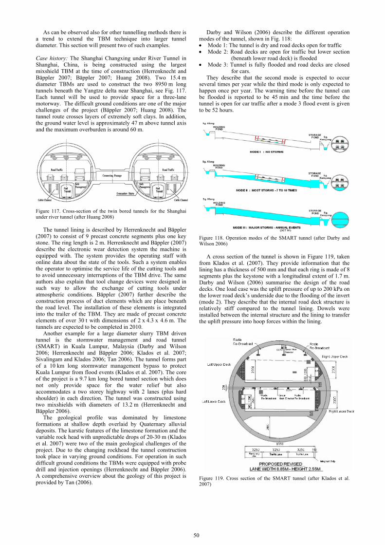
50
As can be observed also for other tunnelling methods there is a trend to extend the TBM technique into larger tunnel diameter. This section will present two of such examples. Case history: The Shanghai Changxing under River Tunnel in Shanghai, China, is being constructed using the largest mixshield TBM at the time of construction (Herrenknecht and Bäppler 2007; Bäppler 2007; Huang 2008). Two 15.4 m diameter TBMs are used to construct the two 8950 m long tunnels beneath the Yangtze delta near Shanghai, see Fig. 117. Each tunnel will be used to provide space for a three-lane motorway. The difficult ground conditions are one of the major challenges of the project (Bäppler 2007; Huang 2008). The tunnel route crosses layers of extremely soft clays. In addition, the ground water level is approximately 47 m above tunnel axis and the maximum overburden is around 60 m.
Figure 117. Cross-section of the twin bored tunnels for the Shanghai under river tunnel (after Huang 2008)
The tunnel lining is described by Herrenknecht and Bäppler
(2007) to consist of 9 precast concrete segments plus one key stone. The ring length is 2 m. Herrenknecht and Bäppler (2007) describe the electronic wear detection system the machine is equipped with. The system provides the operating staff with online data about the state of the tools. Such a system enables the operator to optimise the service life of the cutting tools and to avoid unnecessary interruptions of the TBM drive. The same authors also explain that tool change devices were designed in such way to allow the exchange of cutting tools under atmospheric conditions. Bäppler (2007) further describe the construction process of duct elements which are place beneath the road level. The installation of these elements is integrated into the trailer of the TBM. They are made of precast concrete elements of over 30 t with dimensions of 2 x 4.3 x 4.6 m. The tunnels are expected to be completed in 2010.
Another example for a large diameter slurry TBM driven tunnel is the stormwater management and road tunnel (SMART) in Kuala Lumpur, Malaysia (Darby and Wilson 2006; Herrenknecht and Bäppler 2006; Klados et al. 2007; Sivalingam and Klados 2006; Tan 2006). The tunnel forms part of a 10 km long stormwater management bypass to protect Kuala Lumpur from flood events (Klados et al. 2007). The core of the project is a 9.7 km long bored tunnel section which does not only provide space for the water relief but also accommodates a two storey highway with 2 lanes (plus hard shoulder) in each direction. The tunnel was constructed using two mixshields with diameters of 13.2 m (Herrenknecht and Bäppler 2006).
The geological profile was dominated by limestone formations at shallow depth overlaid by Quaternary alluvial deposits. The karstic features of the limestone formation and the variable rock head with unpredictable drops of 20-30 m (Klados et al. 2007) were two of the main geological challenges of the project. Due to the changing rockhead the tunnel construction took place in varying ground conditions. For operation in such difficult ground conditions the TBMs were equipped with probe drill and injection openings (Herrenknecht and Bäppler 2006). A comprehensive overview about the geology of this project is provided by Tan (2006).
Darby and Wilson (2006) describe the different operation modes of the tunnel, shown in Fig. 118: • Mode 1: The tunnel is dry and road decks open for traffic • Mode 2: Road decks are open for traffic but lower section
(beneath lower road deck) is flooded • Mode 3: Tunnel is fully flooded and road decks are closed
for cars. They describe that the second mode is expected to occur
several times per year while the third mode is only expected to happen once per year. The warning time before the tunnel can be flooded is reported to be 45 min and the time before the tunnel is open for car traffic after a mode 3 flood event is given to be 52 hours.
Figure 118. Operation modes of the SMART tunnel (after Darby and Wilson 2006)
A cross section of the tunnel is shown in Figure 119, taken from Klados et al. (2007). They provide information that the lining has a thickness of 500 mm and that each ring is made of 8 segments plus the keystone with a longitudinal extent of 1.7 m. Darby and Wilson (2006) summarise the design of the road decks. One load case was the uplift pressure of up to 200 kPa on the lower road deck’s underside due to the flooding of the invert (mode 2). They describe that the internal road deck structure is relatively stiff compared to the tunnel lining. Dowels were installed between the internal structure and the lining to transfer the uplift pressure into hoop forces within the lining.
Figure 119. Cross section of the SMART tunnel (after Klados et al. 2007)

This case study is an example of tunnels that can serve more
than one purpose at the same time. Both, reduction of traffic congestion and flood control are two of the challenges large metropolises face. Such a dual-purpose structure requires a relatively large diameter which is specifically challenging in the difficult ground conditions this tunnel was constructed in.
This case study also demonstrates how to utilize the full cross sectional area of a tunnel efficiently. Krcik (2007) notes that only two thirds of large diameter (referred to as 14 m and more) TBM driven tunnels use the excessive cross section efficiently. The author, therefore, propagates the use of non-circular full face tunnel boring machines.
(2) Earth pressure balance machine Earth Pressure Balance (EPB) machines were developed for the use in weak cohesive soils (BTS 2005). In EPB machines the face support pressure is maintained by filling the excavation chamber with the excavated soil. Under ideal conditions the cohesive soil in the excavation chamber would form a plastic paste with a low permeability (Merrit 2004). However, in reality the soil is most times a mixture of cohesive and cohesionless ground. Therefore, conditioning of the soil is required in order to provide the soil properties which can be used in an EPB shield. The support pressure within the face chamber is regulated by the rate of the soil discharge via a screw conveyor (Merrit and Mair 2008).
Case history: An example for an EPB machine driven tunnel is the M30 motorway tunnel built in Madrid, Spain in 2005-2006 (Herrenknecht and Bäppler 2007; Arnaiz et al. 2007; Herr 2006; Bäppler and Martos 2006). The project consisted of two tunnels each approximately 3,650m long with an outer diameter of 15.20m. Two EPB machines were used for this project. The EPB machines used were the largest in diameter at that time. Once completed each of the tunnels would provide space for a three lane motorway (in each direction) and relieve Madrid’s most congested motorway junction (see Fig. 120). Construction of the tunnels also included excavating cross passages between the two tubes.
Figure 120. Cross section and tunnel alignment of the M30 motorway tunnel (after Arnaiz et al. 2007)
The geological profile, described by Arnaiz et al. (2007), comprised made ground, Quaternary sediments, Tertiary formations of stiff clay and gypsum formation which are interspersed with the clay. Most of the tunnel route was within the clay and the gypsum strata. At its deepest point the tunnel axis is approximately 75 m below ground level.
One of the tunnel boring machines had a new cutting wheel concept which consisted of an inner and an outer cutting wheel (Herrenknecht and Bäppler 2007; Bäppler and Martos 2006). The inner wheel had a diameter of 7 m. Both cutting wheels could be rotated independently achieving a maximum torque of
roughly 125 MNm. Herrenknecht and Bäppler (2007) reported that the double cutting wheel design had improved both the excavation process and the soil conditioning. They also explained that adjusting the inner area to a higher rotational speed had reduced the wear on the outer wheel. The EPB machine had two mixing chambers which could be handled independently. The soil was discharged via three screw conveyors with up to 1.25 m diameter.
The tunnel lining consisted of reinforced concrete segments of 600 mm thickness. Each ring was 2 m long and consisted of 9 segments + 1 keystone (Herr, 2006). The average tunnel advance rate for both tunnels were 15 and 18 m/day with a maximum rate of 46 m/day (Arnaiz et al., 2007). Herr (2006) provides a comparison of this tunnel advance rates with other similar projects which shows that the rate achieved in Madrid was a relatively high one (Fig. 121).
Figure 121. Advance rate of the M30 tunnel compared with other projects (after Herr 2006)
The tunnels pass through densely developed urban area and
cross two of Madrid’s Metro lines. As reported by Arnaiz et al. (2007), the tunnel induced settlement was predicted using the finite difference code FLAC in addition to a semi-empirical method (referred to as Madrid Model, which modelled the settlement trough as a Gaussian curve described by several authors, e.g. Peck 1969; O’Reilly and New 1982). Zones which required protective measures were identified based on the results of these predictions. These comprised mortar piles to enhance stability in the vicinity of the TBM launch shaft, grouting beneath one of the Metro lines, installation of a piled wall to protect adjacent buildings and compensation grouting
Arnaiz et al. (2007) compared the predicted surface settlement (without ground treatment) with measurements taken along the route. The figure shows that most of the measurement points settled less than 10 mm.
This case study demonstrates that large diameter tunnels can be successfully constructed in urban environment even while achieving high advance rates. However, Arnaiz et al (2007) point out that this was only achieved since problematic zones of excessive settlement were identified before excavation started and appropriate protective measures were taken to limit the subsidence of buildings and critical infrastructure to an acceptable level.
While the tunnel for the M30 in Madrid used the largest EPB machine at that time, construction of the Metro Line 9 in Barcelona, also Spain, used a slightly smaller EPB shield (12 m diameter). Frech et al. (2004) reported that the density of existing buildings and the complication of the existing underground structures and the geology posed a great challenge for this project. To address these problems, it was decided to build only one tunnel for the two tracks of the metro line. The tunnel was subdivided into two storeys and it was even possible to integrate stations within the large diameter tunnel. This is an example how it is possible to reduce the impact of underground excavation on existing structures by adapting the tunnel design to the given boundary conditions. More details on the

52
interaction of this tunnel project with existing surface structures will be given in Section 3.3.2.
(3) Open face Open face stable tunnelling is well suited for impermeable and temporarily ground conditions. An example for this technique are the Piccadilly Line extension and the Heathrow Express extension, both constructed as part of the Terminal 5 project in London Heathrow, UK (Williams 2008). Both tunnels were constructed in London Clay which is a very stiff, high plasticity overconsolidated clay. London Clay is well suited for tunnelling (the first tunnel shield was invented by Brunel for a tunnel leading through London Clay beneath the river Thames).
The tunnels for the Piccadilly Line extension had an outer diameter of 4.81 m. The project comprised approximately 1.6 km twin tunnels. The TBM used for these tunnels were equipped with a boom-mounted road header. The Heathrow Express extension tunnels were also twin tunnels and had an outer diameter of 6.1 m and a length of 1.7 km. The TBM was equipped with a back-hoe. Both TBMs were equipped with face-breasting plates. These increased face stability during excavation.
The tunnels of both projects were excavated beneath live airport taxiways which remained operational during the construction period. Limiting surface settlement, therefore, was a key aspect of the project. In addition, the Heathrow Express extension tunnels also pass beneath the existing Piccadilly Line tunnels of London Underground, which required further control of ground movements.
3.2.3 Conventional tunnelling
Sprayed Concrete Lining (SCL) can also be adopted in soft ground conditions. The construction work for the new Terminal 5 at Heathrow Airport, London, UK included various SCL structures with a total length of over 1100 m (Hilar et al. 2005; Staerk and Jaeger 2007; Williams 2008).
Hilar et al. (2005) reported the construction of a tunnel as part of the Heathrow T5 project. The tunnel was relatively short in its dimensions (40 m long with a internal diameter of 4.15 m). It was used as a launch chamber of a TBM driven tunnel. A new method, referred to as Lasershell, was employed when constructing the SCL. This technique is a combination of sophisticated surveying equipment with other features such as the use of fibre reinforced concrete.
Fibre reinforced concrete allows the construction of the concrete shell and its reinforcement in one step. One of the main advantages of this technique is a better quality of the lining since problems with overshadowing when bringing in the sprayed concrete are reduced compared to conventional reinforcement (Hilar et al., 2005). It is also beneficial in terms of health and safety since the work in the unsupported area of the tunnel face is minimised. Hilar et al. (2005) reports that with this method production rates are higher then when conventional SCL is adopted.
The Lasershell method combines the advantages of using fibre reinforced concrete with the use of a laser distometer which records the location of the tunnel face and/or the lining. A computer system then compares this information with the programmed 3D geometrical model. This enables a real time control of the lining thickness. The lining comprised three layers (Hilar et al. 2005). The first one had a thickness of 75 mm and had the function to give initial ground support. Afterwards the structural layer with a thickness of 200 to 250 mm was installed. Both, the initial and the structural layers were reinforced using steel fibres. After completion of the excavation a finishing layer with a thickness of 50 mm was brought in. This layer was not reinforced but hand finished in order to provide a smooth lining surface (see Fig. 122).
The tunnel face was inclined (angle to the horizontal axis approx. 70°, Jones et al. 2008) which further increased stability
of the tunnel. This shape was also used in order to reduce surface settlement – a crucial issue when tunnelling beneath of the world’s busiest airport.
Figure 122. Lining sequence of the tunnel constructed using Lasershell method (after Jones et al. 2008)
An extensive monitoring programme was carried out both on
the surface and subsurface/tunnel level. Jones et al. (2008) calculates the volume loss from surface measurements of the transverse settlement profile. A volume loss of approximately 0.28 % was calculated along measurement sections which were located above the tunnel face. The authors also present data which were taken 2 weeks after completion of the tunnel. Fitting a Gaussian curve (O’Reilly and New 1982) with a trough width k of 0.5 (typical for London Clay) would give a volume loss of 0.63 %. The volume loss based on trapezoidal integration of the settlement measurements was up to 1.1 % indicating that the settlement trough was wider than expected (although very close to the design volume loss prediction of 1.1 %). The ratio of settlement occurring ahead of the tunnel face to the settlement thereafter was between 43 to 53 %.
The monitoring programme was accomplished by a set of fully 3D numerical analyses using the finite difference code FLAC3D (Jones et al., 2008). After an initial length of the 3D model was excavated at once, tunnel excavation was simulated step-by-step by removing soil slices of 1 m thickness at the tunnel face. The lining was installed subsequently. Jones et al. report that the numerical analysis predicted a volume loss of 1.47 % which is above the measured value. It is also reported that the settlement trough of the numerical analysis is too wide compared to a Gaussian curve fitted through the measurements. This is a result obtained in most analyses of tunnelling in overconsolidated soils such as London Clay. Standing and Potts (2008) after reviewing a number of papers on numerical analyses of tunnelling conclude that realistic predictions of tunnelling in such boundary conditions have not achieved yet without incorporating some sort of empirical factor into the numerical analysis. They, consequently, refer to numerical analysis of Greenfield sites affected by tunnelling in overconsolidated soil conditions as a “holy grail” in numerical analysis.
Although the dimensions of the tunnel presented in this case study were not extraordinary the circumstances of building an underground excavation beneath a busy airport under full operation are representative for many tunnelling projects in

congested areas. This case study demonstrates the importance of an extensive monitoring programme combined with comprehensive in-tunnel measurements and numerical modelling in order to keep surface settlements within given limits provided by the client. The case study also shows how state-of-the-art tunnel equipment can further reduce the health and safety risk tunnelling operating staff is exposed to during their work.
3.2.4 Other methods
There is a wide range of tunnelling methods which are neither classified as TBM tunnelling nor conventional method. An example for such an alternative method is immersed tunnels. This method offers significant advantages compared to a TBM driven tunnel when a waterway is to be crossed. Since immersed tunnels do not require a minimum overburden for the stability of the tunnel (or the tunnel construction process) they can be built shallower than bored tunnels. Consequently they offer much flatter gradients which results in shorter tunnels. Another advantage of these tunnels is that they are not bound to a circular cross section. Using a rectangular shape offers particularly for road tunnels a much more economic use of the tunnel space. Further advantages such as the ability to survive earthquakes undamaged are listed by Ingerslev (2007).
The world’s deepest immersed tunnel has been constructed under the Bosporus in Istanbul (Turkey) as part of a railway project. Grantz et al. (2007) report that the shallowest element of the tunnel is 40 m deep which is twice as deep as most immersed tunnels built until now. The deepest section is at depth of 58 m below sea level. Grantz et al. (2007) also highlight that the immersed tunnel is joined in deep water with TBM-driven tunnels. From both sides TBMs will bore circular tunnels into receiving sleeves at the end of the immersed tunnel section.
In his state-of-the-art lecture, Ingerslev (2007) refers to the ability of immersed tunnels to sustain earthquakes. Given the complex geological situation near the fault zone between Europe and Asia, seismic design was a major aspect of the project. Grantz et al. (2007) reported that a large area of the tunnels foundation was treated by compaction grouting in order to reduce the risk of liquefaction.
Apart from its depth and the exposure to seismic activity there were other extraordinary challenges at this project: The Bosporus is one of the world’s busiest water ways. In combination with the complex currents (Grantz et al. 2007, report up to 6 knots) experienced, placing the segments was a difficult task. Tunnel segments were floated when the surface current was below 3 knots.
In order to reduce the construction time used for dredging and floating, a new tunnelling concept, referred to as TIMBY, has been developed by the companies Herrenknecht and Bouygues which combines the advantages of immersed and TBM driven tunnels. It enables the tunnel to be built as an double-O-tube, although other cross sectional shapes such as ellipses or circular tubes are also possible. (Bäppler et al. 2006). An excavator mechanism is integrated into the shield. Therefore, the dredging operations prior to the launch of the TBM can be potentially reduced compared to immersed tunnel construction. The tunnel lining is erected by the TBM, omitting the complex operation of floating the immersed tunnel segments into position.
3.3 Managing risks and mitigation measures
3.3.1 Controlling ground water inflow
(1) Dewatering In most cases, deep excavations are carried out under groundwater table. Therefore a lowering of the ground water or a construction of a watertight excavation pit with a following
pump out is often necessary to be able to work under dry conditions. According to Eurocode 7, the water may be removed from the ground (i) by gravity drainage; (ii) by pumping from sumps, well points or bored wells; or (iii) by electro-osmosis. A description of several types of dewatering and the corresponding design assumptions is given by Smoltczyk (2003).
(2) Low permeability structural elements Low permeable structural elements are required when an almost watertight excavation pit is intended. The permeability of the retaining walls usually causes fewer difficulties, if an applicable system is selected as for example a concrete diaphragm wall or a sheet pile wall. It is often more problematic to make sure that the permeability of a sealing bottom is low enough. Sometimes an already existing impermeable natural layer can be integrated in the excavation pit by designing retaining walls with a sufficient depth. When such layers are not reachable with economic effort, artificial sealing bottoms have to be installed. This can be achieved by under-water concrete, jet grout slabs or sealing layers of gel materials. Even though, a certain amount of water inflow cannot be avoided and has to be considered.
(3) Jet grout slabs as sealing bottom Shortly after the authorities of Berlin prohibited the use of water glass for bottom sealing in the middle of nineties, a plenty of jet grout slabs were installed in the centre of Berlin to enable high number of deep excavations to be carried out without lowering the ground water table. This risk carrying type of sealing imposes high requirements on the design and construction. In general jet grout slabs are distinguished between high and low lying slabs. The former has to be tied-back due to the uplift forces and are placed only 1 to 2 m below the foundation slab. The latter is charged by the above lying soil. For the construction of jet grout slabs inside the Berlin soils, which consist mainly of sand and gravel layers with inclusions of boulders and brown coal, the following parameters are approved (Hartmann et al. 2002): Jet diameter = 4.5 – 6.0 mm; Pressure of grouting material= 300 - 420 bar; Air pressure = 8 -12 bar; Flow rate = 350 – 420 l/min; Time of pulling = 8 – 12 min/m, and Rotation speed = 3 – 5 r/min.
The pattern shown in Fig. 123 has often been used for jet grouting slab installation in the past, where the secondary rows are achieved with a greater height. The columns of the secondary row are built higher to cover pin holes. Case histories of jet grout slabs have been reported by Reichert et al. (2002) using low lying slab in boulder layer; Hartmann et al. (2002) using high and low lying slab; and Borchert et al. (2006) using double layer slab to avoid pin holes. Other papers concerning the permeability of excavation pits include: • Lehtonen and Sintonen (2007) for presenting “a new
method to make totally watertight sheet piling”. In this method, sheet piles are embedded in soil with a continuous and simultaneous cement grouting;
• Measurements of pore water pressure around a semi-permeable contiguous bored pile wall in clay as presented by Richards et al. (2006 ; 2007).
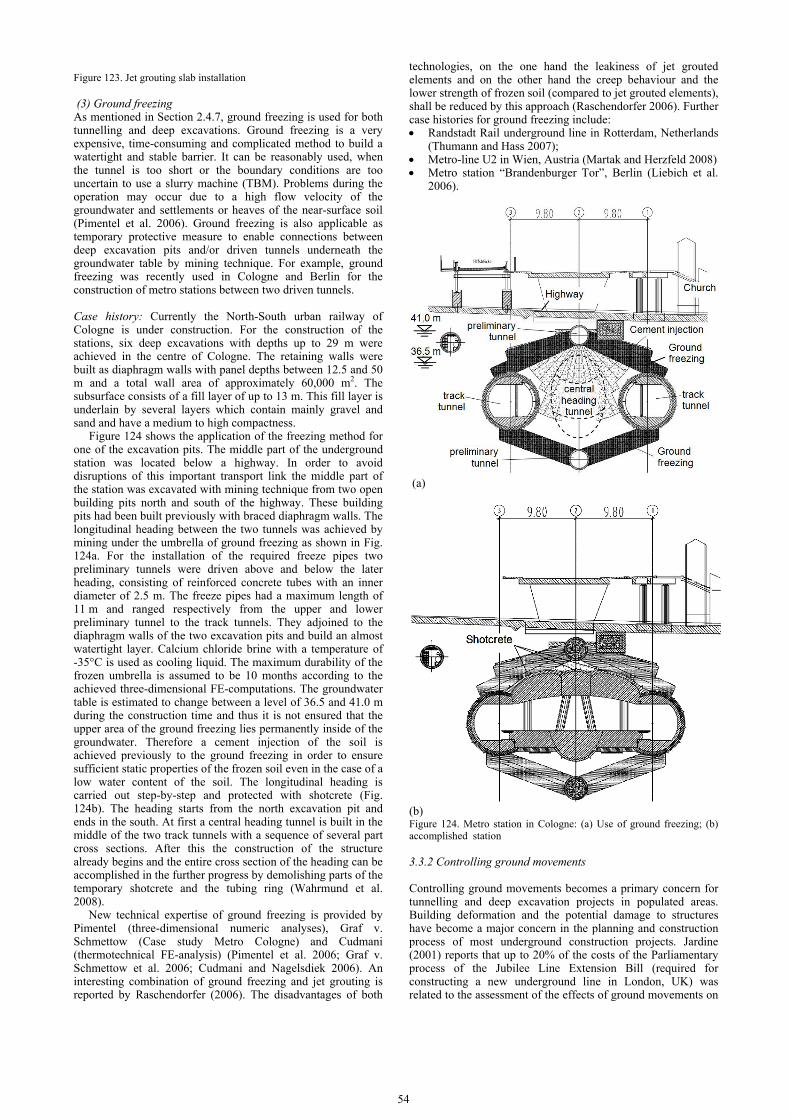
54
Figure 123. Jet grouting slab installation
(3) Ground freezing As mentioned in Section 2.4.7, ground freezing is used for both tunnelling and deep excavations. Ground freezing is a very expensive, time-consuming and complicated method to build a watertight and stable barrier. It can be reasonably used, when the tunnel is too short or the boundary conditions are too uncertain to use a slurry machine (TBM). Problems during the operation may occur due to a high flow velocity of the groundwater and settlements or heaves of the near-surface soil (Pimentel et al. 2006). Ground freezing is also applicable as temporary protective measure to enable connections between deep excavation pits and/or driven tunnels underneath the groundwater table by mining technique. For example, ground freezing was recently used in Cologne and Berlin for the construction of metro stations between two driven tunnels.
Case history: Currently the North-South urban railway of Cologne is under construction. For the construction of the stations, six deep excavations with depths up to 29 m were achieved in the centre of Cologne. The retaining walls were built as diaphragm walls with panel depths between 12.5 and 50 m and a total wall area of approximately 60,000 m2. The subsurface consists of a fill layer of up to 13 m. This fill layer is underlain by several layers which contain mainly gravel and sand and have a medium to high compactness.
Figure 124 shows the application of the freezing method for one of the excavation pits. The middle part of the underground station was located below a highway. In order to avoid disruptions of this important transport link the middle part of the station was excavated with mining technique from two open building pits north and south of the highway. These building pits had been built previously with braced diaphragm walls. The longitudinal heading between the two tunnels was achieved by mining under the umbrella of ground freezing as shown in Fig. 124a. For the installation of the required freeze pipes two preliminary tunnels were driven above and below the later heading, consisting of reinforced concrete tubes with an inner diameter of 2.5 m. The freeze pipes had a maximum length of 11 m and ranged respectively from the upper and lower preliminary tunnel to the track tunnels. They adjoined to the diaphragm walls of the two excavation pits and build an almost watertight layer. Calcium chloride brine with a temperature of -35°C is used as cooling liquid. The maximum durability of the frozen umbrella is assumed to be 10 months according to the achieved three-dimensional FE-computations. The groundwater table is estimated to change between a level of 36.5 and 41.0 m during the construction time and thus it is not ensured that the upper area of the ground freezing lies permanently inside of the groundwater. Therefore a cement injection of the soil is achieved previously to the ground freezing in order to ensure sufficient static properties of the frozen soil even in the case of a low water content of the soil. The longitudinal heading is carried out step-by-step and protected with shotcrete (Fig. 124b). The heading starts from the north excavation pit and ends in the south. At first a central heading tunnel is built in the middle of the two track tunnels with a sequence of several part cross sections. After this the construction of the structure already begins and the entire cross section of the heading can be accomplished in the further progress by demolishing parts of the temporary shotcrete and the tubing ring (Wahrmund et al. 2008).
New technical expertise of ground freezing is provided by Pimentel (three-dimensional numeric analyses), Graf v. Schmettow (Case study Metro Cologne) and Cudmani (thermotechnical FE-analysis) (Pimentel et al. 2006; Graf v. Schmettow et al. 2006; Cudmani and Nagelsdiek 2006). An interesting combination of ground freezing and jet grouting is reported by Raschendorfer (2006). The disadvantages of both
technologies, on the one hand the leakiness of jet grouted elements and on the other hand the creep behaviour and the lower strength of frozen soil (compared to jet grouted elements), shall be reduced by this approach (Raschendorfer 2006). Further case histories for ground freezing include: • Randstadt Rail underground line in Rotterdam, Netherlands
(Thumann and Hass 2007); • Metro-line U2 in Wien, Austria (Martak and Herzfeld 2008) • Metro station “Brandenburger Tor”, Berlin (Liebich et al.
2006).
(a)
(b) Figure 124. Metro station in Cologne: (a) Use of ground freezing; (b) accomplished station
3.3.2 Controlling ground movements
Controlling ground movements becomes a primary concern for tunnelling and deep excavation projects in populated areas. Building deformation and the potential damage to structures have become a major concern in the planning and construction process of most underground construction projects. Jardine (2001) reports that up to 20% of the costs of the Parliamentary process of the Jubilee Line Extension Bill (required for constructing a new underground line in London, UK) was related to the assessment of the effects of ground movements on
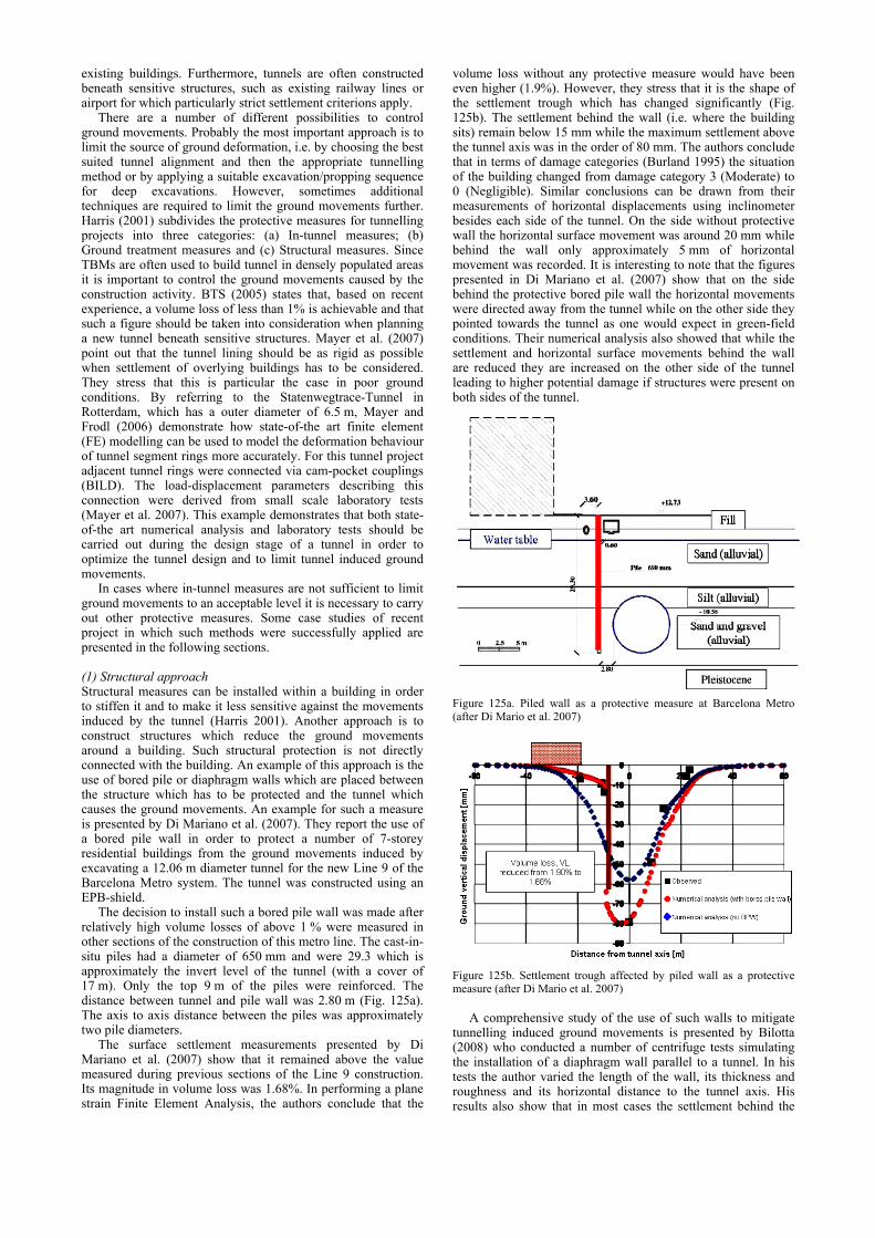
existing buildings. Furthermore, tunnels are often constructed beneath sensitive structures, such as existing railway lines or airport for which particularly strict settlement criterions apply.
There are a number of different possibilities to control ground movements. Probably the most important approach is to limit the source of ground deformation, i.e. by choosing the best suited tunnel alignment and then the appropriate tunnelling method or by applying a suitable excavation/propping sequence for deep excavations. However, sometimes additional techniques are required to limit the ground movements further. Harris (2001) subdivides the protective measures for tunnelling projects into three categories: (a) In-tunnel measures; (b) Ground treatment measures and (c) Structural measures. Since TBMs are often used to build tunnel in densely populated areas it is important to control the ground movements caused by the construction activity. BTS (2005) states that, based on recent experience, a volume loss of less than 1% is achievable and that such a figure should be taken into consideration when planning a new tunnel beneath sensitive structures. Mayer et al. (2007) point out that the tunnel lining should be as rigid as possible when settlement of overlying buildings has to be considered. They stress that this is particular the case in poor ground conditions. By referring to the Statenwegtrace-Tunnel in Rotterdam, which has a outer diameter of 6.5 m, Mayer and Frodl (2006) demonstrate how state-of-the art finite element (FE) modelling can be used to model the deformation behaviour of tunnel segment rings more accurately. For this tunnel project adjacent tunnel rings were connected via cam-pocket couplings (BILD). The load-displacement parameters describing this connection were derived from small scale laboratory tests (Mayer et al. 2007). This example demonstrates that both state-of-the art numerical analysis and laboratory tests should be carried out during the design stage of a tunnel in order to optimize the tunnel design and to limit tunnel induced ground movements.
In cases where in-tunnel measures are not sufficient to limit ground movements to an acceptable level it is necessary to carry out other protective measures. Some case studies of recent project in which such methods were successfully applied are presented in the following sections.
(1) Structural approach Structural measures can be installed within a building in order to stiffen it and to make it less sensitive against the movements induced by the tunnel (Harris 2001). Another approach is to construct structures which reduce the ground movements around a building. Such structural protection is not directly connected with the building. An example of this approach is the use of bored pile or diaphragm walls which are placed between the structure which has to be protected and the tunnel which causes the ground movements. An example for such a measure is presented by Di Mariano et al. (2007). They report the use of a bored pile wall in order to protect a number of 7-storey residential buildings from the ground movements induced by excavating a 12.06 m diameter tunnel for the new Line 9 of the Barcelona Metro system. The tunnel was constructed using an EPB-shield.
The decision to install such a bored pile wall was made after relatively high volume losses of above 1 % were measured in other sections of the construction of this metro line. The cast-in-situ piles had a diameter of 650 mm and were 29.3 which is approximately the invert level of the tunnel (with a cover of 17 m). Only the top 9 m of the piles were reinforced. The distance between tunnel and pile wall was 2.80 m (Fig. 125a). The axis to axis distance between the piles was approximately two pile diameters.
The surface settlement measurements presented by Di Mariano et al. (2007) show that it remained above the value measured during previous sections of the Line 9 construction. Its magnitude in volume loss was 1.68%. In performing a plane strain Finite Element Analysis, the authors conclude that the
volume loss without any protective measure would have been even higher (1.9%). However, they stress that it is the shape of the settlement trough which has changed significantly (Fig. 125b). The settlement behind the wall (i.e. where the building sits) remain below 15 mm while the maximum settlement above the tunnel axis was in the order of 80 mm. The authors conclude that in terms of damage categories (Burland 1995) the situation of the building changed from damage category 3 (Moderate) to 0 (Negligible). Similar conclusions can be drawn from their measurements of horizontal displacements using inclinometer besides each side of the tunnel. On the side without protective wall the horizontal surface movement was around 20 mm while behind the wall only approximately 5 mm of horizontal movement was recorded. It is interesting to note that the figures presented in Di Mariano et al. (2007) show that on the side behind the protective bored pile wall the horizontal movements were directed away from the tunnel while on the other side they pointed towards the tunnel as one would expect in green-field conditions. Their numerical analysis also showed that while the settlement and horizontal surface movements behind the wall are reduced they are increased on the other side of the tunnel leading to higher potential damage if structures were present on both sides of the tunnel.
Figure 125a. Piled wall as a protective measure at Barcelona Metro (after Di Mario et al. 2007)
Figure 125b. Settlement trough affected by piled wall as a protective measure (after Di Mario et al. 2007)
A comprehensive study of the use of such walls to mitigate tunnelling induced ground movements is presented by Bilotta (2008) who conducted a number of centrifuge tests simulating the installation of a diaphragm wall parallel to a tunnel. In his tests the author varied the length of the wall, its thickness and roughness and its horizontal distance to the tunnel axis. His results also show that in most cases the settlement behind the

56
wall reduces while in front of the wall (i.e. where the tunnel is) the settlement increases. Bilotta (2008) introduced a dimensionless efficiency parameter to compare the settlement immediately behind the wall with that which would occur if no such wall would be present. Bilotta (2008) concluded that the effectiveness of the wall mainly depends on its length. He also concluded that there is a difference between smooth and rough wall and that a rough wall, if it was too short, could have a detrimental effect on the movement behind the wall (i.e. a negative efficiency parameter). Bilotta (2008), therefore, recommends that a rough wall should be founded at least half a diameter beneath tunnel invert while for a smooth wall he concludes that the wall should be founded at or below tunnel axis level. (2) Monitoring and active compensation Compensation grouting is an active measure to mitigate tunnel induced ground movements and its effects on existing structures. The principle of this method has been introduced in Section 2.6.6. More detailed description of compensation grouting is given by Harris (2001), Rawlings et al. (2000), Kuesel and Allgaeuer (2008), Kummerer et al. (2008). This method is often applied in urban areas where structures such as buildings or infrastructure tunnels have to be protected. However, finding a suitable workspace to install the TAMs is often problematic in congested areas and consequently different approaches for the installation of TAMs have been developed. Harris (2001) distinguishes between sub-vertical and sub-horizontal TAM installation. The first one would be from the surface or from the basement of a building while the latter would represent drilling from a shaft (often purpose-built for compensation grouting) or from existing tunnels.
Each TAM has a number of ports through which the grout can be injected and a double packer system is used to control at which port grout is injected. Kuesel and Allgaeuer (2008) list four stages over which the grouting process is carried out: 1) Pre-treatment is undertaken in order to “pre-stress” the
ground and to ensure that the subsequent grouting has an immediate effect on the overlying structures.
2) Pre-heave is then carried out before the structure is affected by the TBM drive. It compensates the settlement caused by installation of the TAMs.
3) Compensation grouting is applied once the building is within the influence zone of the tunnel. It has a mitigating effect on the settlement caused by the tunnel excavation.
4) Post-grouting tightens the ground after the TBM drive in order to minimise long-term settlement.
Compensation grouting is now a key technique when constructing tunnels in densely populated areas. An example for such conditions is the construction of the North-South Urban Light Railway in Cologne, Germany. It is one of the major infrastructure projects currently being undertaken in Germany (Buecker et al. 2006; Handke and Tempel 2007; Koenemann et al. 2007; Dinglinger and Jakobs 2007; Ruttkamp and Wahrmund 2007; Kuesel and Allgaeuer 2008). The project comprises of 2 x 3860 m tunnels with outer diameters of 6.8 and 8.4 m. The larger of the two tunnel diameter was chosen so that it is possible to integrate the station platform within the tunnel tube in order to reduce the space required when constructing the stations (Ruttkamp and Wahrmund 2007). Most of the route is within Quaternary and Tertiary layers made of gravel, sand and clayey silt and brown coal with the occurrence of pebbles and boulders. Since the two thousands years of history in Cologne, there are also relatively extensive areas of made ground/fillings which required special attention in archaeological terms. The tunnel route also crossed through the fillings of an old Roman port next to the River Rhine.
The control of settlement was a major issue in this project since the tunnel route crosses beneath the densely populated city center. Koenemann et al (2007) reported that around 1500 properties were within the influence of the tunnel construction.
An extensive programme of protective measures was, therefore, set up along the tunnel route which accounted for approximately 20 % of the costs of the structural works (Koenemann et al. 2007). Compensation grouting was applied to seven areas protecting 48 buildings from tunnelling induced subsidence. The total drilling length for all TAMs was 14.5 km and they covered an area of approximately 6.780 m2 (Kuesel and Allgaeuer 2008).
In most cases the TAMs were drilled horizontally from shafts and formed an umbrella beneath the structure which had to be protected. These umbrellas consisted of 2 layers and the drilling length varied between 20.5 and 52.5 m (Buecker et al. 2006). The depth of the shafts was between 11 and 17 m below ground level. Kuesel and Allgaeuer (2008) describe the extensive measurement system which was installed to monitor the building behaviour and to control the grouting procedure. The building settlement was measured using a liquid level gauge system. Knitsch (2008) states that this technique has proved extremely effective in a number of projects, highlighting the rapid response time combined with a high accuracy. Kuesel and Allgaeuer (2008) report the accuracy to be +/-0.2 mm. The sensors of this system were installed in approximately 5 m distance to each other.
Continuous data collection and their evaluation and documentation are a core aspect of the compensation grouting method. Mayer et al. (2004) and Knitsch (2008) conclude that this method is only practicable with high-performance IT systems which are able to visualise the complex data acquired from several individual processes. A similar system as described by Knitsch (2008) was used for the Cologne project. This system, as summarised by Mayer et al. (2004) and Kuessel and Allgaeuer (2008), comprised four functions: (a) Evaluation of required grouting volume based on real-time measurements; (b) Monitoring and processing of real-time measurements; (c) Reporting; and (d) Archiving. Based on the data of the current settlement profile, the system calculates the grouting parameters for the forthcoming operations and suggest these values to the operating engineer. The settlement profile can be visualised to allow the engineer to assess the effectiveness of the grouting operation in real-time. An example is shown in Fig. 126.
Figure 126. Visualisation of compensation grouting
Compensation grouting was also required in the vicinity of a
cross over cavern to be constructed beneath a densely populated area. Ruttkamp and Wahrmund (2007) report that it was not possible to place TAMs horizontally from a shaft structure in order to protect buildings which were founded on a raft. Instead, the TAMs were drilled in an inclined angle which was drilled parallel to a pipe arch. The pipe arch was placed in order to provide a better reaction for the grouting operation. The building settlement after completion of the running tunnels were less than 5 mm. Ruttkamp and Wahrmund (2007) note that the inclined angle had no effect on the effectiveness of the method.

Another case study in which the TAMs were installed sub-horizontally is presented by Kummerer et al. (2007; 2008). The construction of two tunnels in Bologna, Italy, required mitigation measures to protect an existing brick railway viaduct. The tunnels were part of the highspeed railway line between Napoli and Milano and had a diameter of 9.4 m. The allowable settlement criterion was that two adjacent columns of the viaduct would have a differential settlement of 1/3000 or less. This was equivalent of a settlement difference of 2.7 to 5.3 mm between the columns. The tunnels were excavated using EPB machines. Tunnelling took place within heterogeneous alluvial strata with mainly gravely and sandy soil together with lenses of clay. The soil cover above the tunnel crown was approximately 20 m. Kummerer et al. (2007) reported that it was planned initially to perform the compensation grouting from vertical shafts, similar to the Cologne case study discussed above. However, limitations in space and ground access required a different solution. Hence, the Horizontal Directional Drilling (HDD) technique was employed to install the TAMs beneath the bridge foundations, as shown in Fig. 127.
Figure 127. Schematic view of Horizontal Directional Drilling bore for compensation grouting (Kummerer et al. 2007)
The maximum length of HDD drill was 68 m and the total
length of all TAMs was 5,000 m covering an area of 3,200 m2. Kummerer et al. (2007) further described the measurement system which consisted of a liquid level gauge system comprising 93 measurement points over three levels. All measurements were related to a fixed gauge located 50 m away from the bridge. Readings were taken every 10 min.
During the first TBM drive beneath the bridge a volume loss of around 1 % was measured (Kummerer et al 2007). The advance rate of the TBM was 18 m per day. The second tunnel construction was at a certain offset to the bridge. Consequently Kummerer et al. (2007) reported that a rotation of the bridge was observed. Kummerer et al. (2008) summarized that after completion of the TBM excavation the differential settlement was below the value specified by the client.
3.3.3 Monitoring construction process
The construction of a deep excavation requires not only a sophisticated design but also a high quality monitoring. Monitoring is necessary to verify the theoretical approaches of the design stage and to control the stability of the retaining systems during the construction process. For deep excavations monitoring is the most important measure for the identification und avoiding of damages and cannot be neglected according the state of art (Katzenbach et al. 2006). Monitoring data can also help to diagnose the failure mechanism when unexpected wall movements occur. In that case targeted measures for strengthening of the wall can be selected (Candogan and
Düzceer 2001). During the construction process of the excavation pit also settlements of the adjacent soil may be caused, e. g. due to vibrating-in a sheet pile wall. By the measurement of the vibration an exceeding of acceptable values can be observed at an early stage and damages can be avoided (Horodecki and Dembicki 2007).
The examined monitoring data of achieved deep excavations can be looked up both in several summaries and in single case studies in the technical literature. M. Long provided in 2001 a scheduler summary of some 300 worldwide case histories of wall and ground movements due to deep excavations (Long 2001). Yoo (2001) summarized 62 case histories of braced and anchored walls in multilayered ground conditions of residual soils overlying rock stratum, which are frequently encountered in the urban areas of Korea (Yoo 2001).
Further case histories of monitored retaining walls: • Circular diaphragm wall (Anagnostopoulos and Georgiadis
2001); • CFA pile wall in a heavy overconsolidated clay (Szepeházi
et al. 2001); • Multi-anchored diaphragm in pyroclastic soil (Fenelli and
Ramondini 1997); • Soil nailed excavations (Shiu et al. 1997; Thut et al. 2003) ; • Sheet piling wall (Sokolić and Vukadinović 2007); • Bored pile walls (Richards et al. 2006, Richards et al. 2007); • Deep basement excavation in Berlin (Triantafyllidis et al.
1997); • Three tied-back diaphragm walls in the alluvial soil of
Taipei (Liao and Hsieh 2002); • Short diaphragm wall panel (Ng et al. 1999).
The above summarised tunnelling case studies have also illustrated the importance of monitoring during tunnel excavation. This is particularly the case for conventional excavation technique (Jones et al., 2008) and when protective measures are operated in response to the measured ground and building movements. The case histories for Barcelona Metro (Di Mariano et al. 2007), Madrid M30 (Arnaiz et al. 2007), Cologne Metro (Koenemann et al. 2007) and Bologna (Kummerer et al. 2007) all highlighted the importance of high quality measurements during tunnel construction.
3.4 Conclusions
A number of case studies for deep excavations and tunnelling projects are presented. The projects discussed in this report show that there is a trend for excavations and tunnels to be constructed under increasingly difficult circumstances including geological and geotechnical challenges, deeper and larger dimensions and close proximity to existing structures.
In many of the presented case studies, ground movements were a major concern of the projects and adequate mitigation measures were a pivotal part of the design. For deep excavations, the report discussed different construction methods and their effects on soil displacement. For tunnels, the application of different protective measures such as protective bored pile walls and compensation grouting were presented.
The trend that tunnels of increasingly large diameters being constructed can be seen in numerous case studies. In some cases the large diameter was also chosen in order to reduce ground movements (compared to the construction of twin tubes). While large diameter circular tunnels provide lateral extent for multi-lane roads, their height is often difficult to use. Multi-purpose tunnel which combine for example storm water management and road traffic demonstrate how to maximize the use of modern tunnels. The report also highlighted newest developments in the TBM design which allows such large tunnels to be constructed in difficult ground conditions.
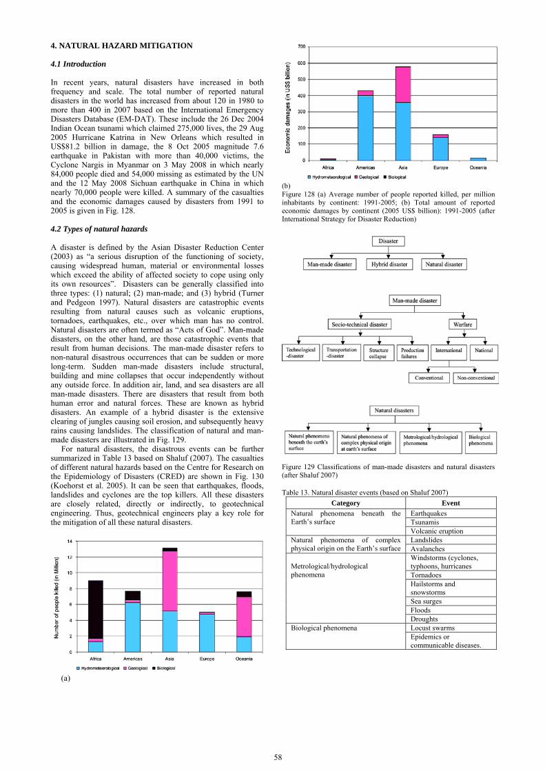
58
4. NATURAL HAZARD MITIGATION
4.1 Introduction
In recent years, natural disasters have increased in both frequency and scale. The total number of reported natural disasters in the world has increased from about 120 in 1980 to more than 400 in 2007 based on the International Emergency Disasters Database (EM-DAT). These include the 26 Dec 2004 Indian Ocean tsunami which claimed 275,000 lives, the 29 Aug 2005 Hurricane Katrina in New Orleans which resulted in US$81.2 billion in damage, the 8 Oct 2005 magnitude 7.6 earthquake in Pakistan with more than 40,000 victims, the Cyclone Nargis in Myanmar on 3 May 2008 in which nearly 84,000 people died and 54,000 missing as estimated by the UN and the 12 May 2008 Sichuan earthquake in China in which nearly 70,000 people were killed. A summary of the casualties and the economic damages caused by disasters from 1991 to 2005 is given in Fig. 128. 4.2 Types of natural hazards
A disaster is defined by the Asian Disaster Reduction Center (2003) as “a serious disruption of the functioning of society, causing widespread human, material or environmental losses which exceed the ability of affected society to cope using only its own resources”. Disasters can be generally classified into three types: (1) natural; (2) man-made; and (3) hybrid (Turner and Pedgeon 1997). Natural disasters are catastrophic events resulting from natural causes such as volcanic eruptions, tornadoes, earthquakes, etc., over which man has no control. Natural disasters are often termed as “Acts of God”. Man-made disasters, on the other hand, are those catastrophic events that result from human decisions. The man-made disaster refers to non-natural disastrous occurrences that can be sudden or more long-term. Sudden man-made disasters include structural, building and mine collapses that occur independently without any outside force. In addition air, land, and sea disasters are all man-made disasters. There are disasters that result from both human error and natural forces. These are known as hybrid disasters. An example of a hybrid disaster is the extensive clearing of jungles causing soil erosion, and subsequently heavy rains causing landslides. The classification of natural and man-made disasters are illustrated in Fig. 129.
For natural disasters, the disastrous events can be further summarized in Table 13 based on Shaluf (2007). The casualties of different natural hazards based on the Centre for Research on the Epidemiology of Disasters (CRED) are shown in Fig. 130 (Koehorst et al. 2005). It can be seen that earthquakes, floods, landslides and cyclones are the top killers. All these disasters are closely related, directly or indirectly, to geotechnical engineering. Thus, geotechnical engineers play a key role for the mitigation of all these natural disasters.
(a)
(b) Figure 128 (a) Average number of people reported killed, per million inhabitants by continent: 1991-2005; (b) Total amount of reported economic damages by continent (2005 US$ billion): 1991-2005 (after International Strategy for Disaster Reduction)
Figure 129 Classifications of man-made disasters and natural disasters (after Shaluf 2007) Table 13. Natural disaster events (based on Shaluf 2007)
Category Event Natural phenomena beneath the Earth’s surface
Earthquakes Tsunamis Volcanic eruption
Natural phenomena of complex physical origin on the Earth’s surface
Landslides Avalanches
Metrological/hydrological phenomena
Windstorms (cyclones, typhoons, hurricanes Tornadoes Hailstorms and snowstorms Sea surges Floods Droughts
Biological phenomena Locust swarms Epidemics or communicable diseases.

Figure 130 Casualties of different natural hazards based on CRED (Koehorst et al. 2005)
According to Geotechnet, the European Geotechnical Thematic Network, the risk management of natural disasters basically involves the following issues (Koehorst et al. 2005): • Risk awareness and perception, i.e. the societal awareness,
understanding and experience of risk, as well as the societal attitude how to deal with risks.
• Hazard risk identification, i.e. the objective and quantifiable identification of the hazard risk.
• Hazard risk assessment, i.e. vulnerability assessment and the assessment of potential impacts of the hazards coherence of the influencing factors and the societal impact of the risk.
• Risk reduction measures, i.e. deployment of preventive and curative measures to reduce natural hazard risk to agreed levels.
As the topic of this report deals with construction, only construction methods that are related to the mitigation and rehabilitation of natural hazards or disasters such as landslides, earthquakes and river and coastal protections are discussed. 4.3. Mitigation against landslides
4.3.1 Types of landslides
Landslides have been classified in general as fall, topples, slides (rotational and translational), lateral spreads, flows and composites of different types. The main causes of landslides have been identified as (1) precipitation and infiltration such as intensive and prolonged rainfall and snowmelt, (2) change in surface water level, (3) earthquake, (4) flooding, stream coastal erosion, (5) natural dam failure, (6) human effects such as cuts and construction, (7) volcanic eruption, or (8) in combination of any of the above (Schuster and Wiecworek 2002). A more detailed checklist of the causes of landslide is given in Table 14. Although landslides can be triggered off by a number of events, water plays by far the greatest hazard, as shown in Fig. 131 based on the Italian experience (Koehorst et al. 2005).
4.3.2 Landslide risk management
The susceptibility of a slope to land sliding and the frequency of occurrence are components of "hazard". The "risk" associated with landslides includes both the hazard and the consequences. The risk may be defined with respect to economic loss and/or the loss of human life. For regions in which rainfall is the main landslide-triggering event, the major goals of landslide management have been summarized by Koehorst et al. (2005) as follows: • Understanding the link between rainfall and land sliding. • Estimating the frequency of land sliding in different areas. • Prioritising slopes for prevention and remedial action. • Developing early warning systems and disaster mitigation
plans. • Developing approaches for real time hazard during rainfall.
Table 14. Checklist of landslide causes (after Cruden and Varnes 1996) Category Causes
1. Geological causes
a. Weak materials b. Sensitive materials c. Weathered materials d. Sheared materials e. Jointed or fissured materials f. Adversely oriented structural discontinuity fault, unconformity, contact, etc.
2. Morphological causes
a. Tectonic or volcanic uplift b. Glacial rebound c. Fluvial erosion of slope toe d. Wave erosionof slope toe e. Glacial erosion of slope toe f. Erosion of lateral margins g. Subterranean erosion (solution, piping) h. Deposition loading slope or its crest i. Vegetation removal (by forest fire, drought)
3. Physical causes
a. Intense rainfall b. Rapid snow melt c. Prolonged exceptional precipitation d. Rapid drawdown (of floods and tides) e. Earthquake f. Volcanic eruption g. Thawing h. Freeze-and-thaw weathering i. Shrink-and-swell weathering
4. Human cause
a. Excavation of slope or its toe b. Loading of slope or its toe c. Drawdown (of reservoirs) d. Deforestation e. Irrigation f. Mining g. Artificial vibration h. Water leakage from utilities
Figure 131. Landslide trigger mechanisms. (after Koehorst et al. 2005)
Landslide hazard mapping is a common method used in
identifying the potential landslide hazard. Once the hazard locations are identified, part of the mitigation measures can be carried out as geotechnical constructions. Three types of maps can be plotted: (1) Geological risk map; (2) Landslide occurrence map; and (3) Perceived landslide risk map. The first step in any landslide risk management is to set up an inventory (maps) of existing landslides. This is the basic building block of hazard evaluation. Landslide hazard maps generally indicate where landslides are most likely to occur; however the timing of landslides is generally unknown. Exceptions are areas with historical records of landslide events that allow for statistical analyses to be carried out.
Geographic information systems (GIS) have become an important tool for landslide hazard assessment. GIS is a computer based technology designed to capture, store, manipulate, analyse and display diverse sets of spatial or geo-referenced data. Advanced GIS can be used for life span acquisition and management of spatial data and hazard risk. GIS data can be analysed to produce 3D hazard maps draping topography and other data over satellite imagery maps, thus significantly enhancing hazard and risk mapping. There are a
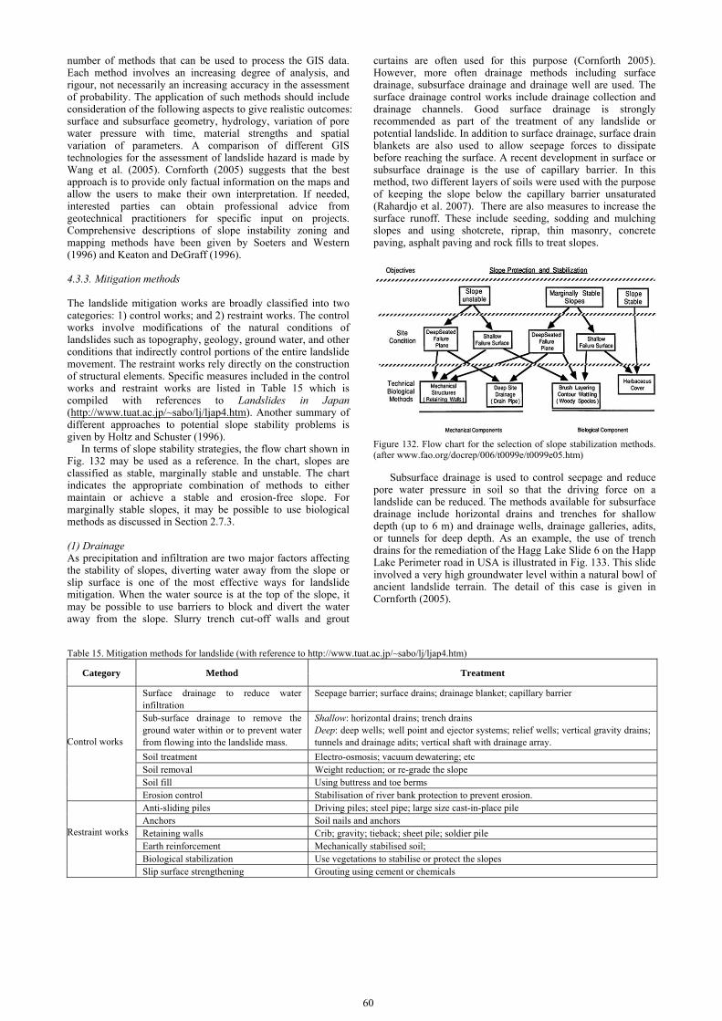
60
number of methods that can be used to process the GIS data. Each method involves an increasing degree of analysis, and rigour, not necessarily an increasing accuracy in the assessment of probability. The application of such methods should include consideration of the following aspects to give realistic outcomes: surface and subsurface geometry, hydrology, variation of pore water pressure with time, material strengths and spatial variation of parameters. A comparison of different GIS technologies for the assessment of landslide hazard is made by Wang et al. (2005). Cornforth (2005) suggests that the best approach is to provide only factual information on the maps and allow the users to make their own interpretation. If needed, interested parties can obtain professional advice from geotechnical practitioners for specific input on projects. Comprehensive descriptions of slope instability zoning and mapping methods have been given by Soeters and Western (1996) and Keaton and DeGraff (1996).
4.3.3. Mitigation methods
The landslide mitigation works are broadly classified into two categories: 1) control works; and 2) restraint works. The control works involve modifications of the natural conditions of landslides such as topography, geology, ground water, and other conditions that indirectly control portions of the entire landslide movement. The restraint works rely directly on the construction of structural elements. Specific measures included in the control works and restraint works are listed in Table 15 which is compiled with references to Landslides in Japan (http://www.tuat.ac.jp/~sabo/lj/ljap4.htm). Another summary of different approaches to potential slope stability problems is given by Holtz and Schuster (1996).
In terms of slope stability strategies, the flow chart shown in Fig. 132 may be used as a reference. In the chart, slopes are classified as stable, marginally stable and unstable. The chart indicates the appropriate combination of methods to either maintain or achieve a stable and erosion-free slope. For marginally stable slopes, it may be possible to use biological methods as discussed in Section 2.7.3.
(1) Drainage As precipitation and infiltration are two major factors affecting the stability of slopes, diverting water away from the slope or slip surface is one of the most effective ways for landslide mitigation. When the water source is at the top of the slope, it may be possible to use barriers to block and divert the water away from the slope. Slurry trench cut-off walls and grout
curtains are often used for this purpose (Cornforth 2005). However, more often drainage methods including surface drainage, subsurface drainage and drainage well are used. The surface drainage control works include drainage collection and drainage channels. Good surface drainage is strongly recommended as part of the treatment of any landslide or potential landslide. In addition to surface drainage, surface drain blankets are also used to allow seepage forces to dissipate before reaching the surface. A recent development in surface or subsurface drainage is the use of capillary barrier. In this method, two different layers of soils were used with the purpose of keeping the slope below the capillary barrier unsaturated (Rahardjo et al. 2007). There are also measures to increase the surface runoff. These include seeding, sodding and mulching slopes and using shotcrete, riprap, thin masonry, concrete paving, asphalt paving and rock fills to treat slopes.
Figure 132. Flow chart for the selection of slope stabilization methods. (after www.fao.org/docrep/006/t0099e/t0099e05.htm)
Subsurface drainage is used to control seepage and reduce pore water pressure in soil so that the driving force on a landslide can be reduced. The methods available for subsurface drainage include horizontal drains and trenches for shallow depth (up to 6 m) and drainage wells, drainage galleries, adits, or tunnels for deep depth. As an example, the use of trench drains for the remediation of the Hagg Lake Slide 6 on the Happ Lake Perimeter road in USA is illustrated in Fig. 133. This slide involved a very high groundwater level within a natural bowl of ancient landslide terrain. The detail of this case is given in Cornforth (2005).
Table 15. Mitigation methods for landslide (with reference to http://www.tuat.ac.jp/~sabo/lj/ljap4.htm)
Category Method Treatment
Control works
Surface drainage to reduce water infiltration
Seepage barrier; surface drains; drainage blanket; capillary barrier
Sub-surface drainage to remove the ground water within or to prevent water from flowing into the landslide mass.
Shallow: horizontal drains; trench drains Deep: deep wells; well point and ejector systems; relief wells; vertical gravity drains; tunnels and drainage adits; vertical shaft with drainage array.
Soil treatment Electro-osmosis; vacuum dewatering; etc Soil removal Weight reduction; or re-grade the slope Soil fill Using buttress and toe berms Erosion control Stabilisation of river bank protection to prevent erosion.
Restraint works
Anti-sliding piles Driving piles; steel pipe; large size cast-in-place pile Anchors Soil nails and anchors Retaining walls Crib; gravity; tieback; sheet pile; soldier pile Earth reinforcement Mechanically stabilised soil; Biological stabilization Use vegetations to stabilise or protect the slopes Slip surface strengthening Grouting using cement or chemicals
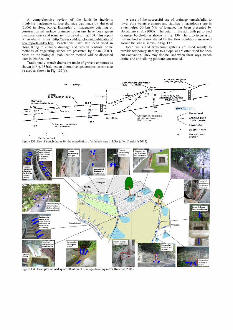
A comprehensive review of the landslide incidents involving inadequate surface drainage was made by Hui et al (2006) in Hong Kong. Examples of inadequate detailing or construction of surface drainage provisions have been given using real cases and some are illustrated in Fig. 134. This report is available from http://www.cedd.gov.hk/eng/publications/ geo_reports/index.htm. Vegetations have also been used in Hong Kong to enhance drainage and erosion controls. Some methods of vegetating slopes are presented by Chan (2007). More on the biological stabilization method will be discussed later in this Section.
Traditionally, trench drains are made of gravels or stones as shown in Fig. 135(a). As an alternative, geocomposites can also be used as shown in Fig. 135(b).
A case of the successful use of drainage tunnels/adits to lower pore waters pressures and stabilize a hazardous slope in Swiss Alps, 50 km NW of Lugano, has been presented by Bonzanigo et al. (2000). The detail of the adit with perforated drainage boreholes is shown in Fig. 136. The effectiveness of this method is demonstrated by the flow conditions measured around the adit as shown in Fig. 137.
Deep wells and well-point systems are used mainly to provide temporary stability to a slope, as are often used for open cut excavation. They may also be used when shear keys, trench drains and anti-sliding piles are constructed.
Figure 133. Use of trench drains for the remediation of a failed slope in USA (after Cornforth 2005)
Figure 134. Examples of inadequate attention of drainage detailing (after Hui et al. 2006)

62
(a) Gravel trench
(b) Trench made of geo-composite Figure 135. Use of trench drain for slope (after Pinzani et al. 2008)
Figure 136. Drainage adit used for an unstable slope in south Alps: (a) Profile; (b) Adit with perforated drainage boreholes (after Bonzanigo et al. 2000).
Figure 137. Cross-section of the slide mass showing groundwater flow vectors and equipotential contours after the drainage adit shown in Fig. 136 was constructed (after Bonzanigo et al. 2000).
Electro-osmosis or vacuum dewatering has also been used for the stabilisation of slopes or embankments (Bjerrum et al. 1967; Casagrande 1983), as described in Section 2.4.6. A case history of using vacuum preloading for the stabilisation of an embankment in Kuching, Malaysia, for the Deepwater Port
Container Terminal is given by Yee et al. (2004). The purpose of using vacuum preloading in this project was mainly to reduce the water content and increase the shear strength of the soil. However, preloading requires time and thus may not be suitable for urgent repair works. (2) Anti-sliding piles Different types of anti-sliding piles are used to stabilize slopes. Some typical arrangements are shown in Fig. 138. Large diameter bore piles or cast-in-situ reinforced concrete piles are often used in one or two rows (see Fig. 138). The piles can either form a tangent or a secant wall or be used isolated with a space in between. They are installed at or near the toe of the slope to intercept the slip surface and stop the movement of the slope. The depths of the piles are determined by the locations of the slip surface which may be deeper in the middle and shallow at the two ends.
Figure 138. Different methods of using anti-sliding piles for slope stabilisation 1: slope surface; 2: potential slip surface (afterWang 2007)
As an example, the use of large size cast-in-situ piles for a slope stabilization project in China is shown in Fig. 139. The piles are installed at a few meters apart (Fig. 139a). The cross-section of the pile can vary but should be larger than one meter. The excavation was done in steps of 1 to 2 m. For each step, the wall of the pit was supported by casting a layer of 20 cm thick concrete as shown in Fig. 139b. After the shaft is excavated, a reinforced concrete pile is cast in-situ (Fig. 139c). This method is simple and economical. However, it is not suitable to be used in soil where seepage is difficult to be controlled. One example of the use of cast-in-situ piles is shown in Fig. 140.
(a)
(b) (c) Figure 139. Installation of cast-in-situ anti-sliding piles (a)&(b) Shaft excavation; (c) Putting reinforcement and pile casting (after Chen 2000)

Figure 140. Use of cat-in-situ reinforced concrete anti-sliding piles for slope stabilization (after Wang 2007)
Reinforced concrete (RC) shafts of 5 m diameter and 22 m deep, as shown in Fig. 141, were used for the rehabilitation of the Macesnik landslide in Slovenia (Mikos 2005). The shafts had both anti-sliding and drainage functions. The solid bottom part (of at least 20% of the shaft length) was embedded into the bed rock. Geosynthetic and 125 mm in diameter pipes were used for the shaft for drainage. For details, see Mikos (2005).
Figure 141. Details of the reinforced concrete shaft (after Mikos 2005).
(3) Ground anchors and soil nails As general ground improvement methods, ground anchors and soil nails have been discussed in Section 2.7.2. These methods have been commonly used for slope stabilisations when a relative competent bearing surface and an anchorage layer are available. The installation of an anchor involves the drilling of an angled hole into an anchorage zone of bedrock or firm soils, inserting a steel bar or stranded wire and grouting the role. Anchors are tied to concrete bearing pads by applying prestressing. Soil nails are normally not pre-stressed. Some typical use of ground anchors or nails together with other methods in slope stabilisation are illustrated in Fig. 142. An example of the use of ground anchors with anti-sliding piles for slope stabilisation is shown in Fig. 143.
Ground anchors or soil nails are commonly used together with metal meshes. As an example, the repair of the San Marcos Road landslide in USA (Tracy and McGolpin 2005) using soil nail and metal mesh system is shown in Fig. 144. Soil nails were installed to lengths of at least 6 m for a design load of 2.7 tons tension on the anchor rod. Spacing is 1.5 m using a hole diameter of 100 mm and a steel nail of 30 mm diameter galvanized and threaded steel bars. There have not been any slope failures since the soil nails were installed (Tracy and McGolpin 2005). Soil nails or ground anchors are also used together with concrete or masonry grids, shotcrete and other
types of slope protection. Some examples are shown in Fig. 145. The effectiveness of using ground anchors or soil nails for slope stabilisation has been demonstrated during the 2008 Sichuan earthquake in China. As shown in Fig. 146, the part of slope stabilised using ground anchors did not collapse during the earthquake.
Figure 142 Use of ground anchors and soil nails in slope stabilisation (a) anchors, (b) anchors together with anti-sliding piles and drains, (c) anchors and soil nails and drains (after Wang 2007)
Figure 143 Use of ground anchor together with anti-sliding piles (after Wang 2007)
Anchors
Anti-sliding pile
Drains
Nails
(a)
(b)
(c)
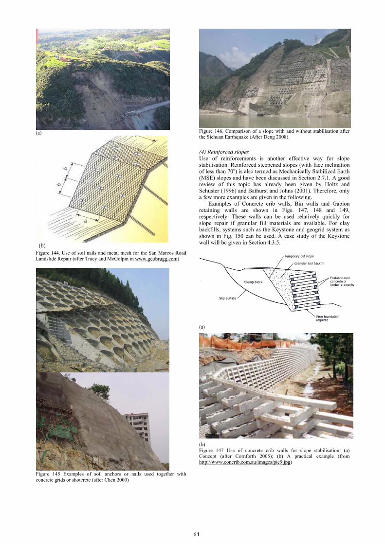
64
(a)
Figure 144. Use of soil nails and metal mesh for the San Marcos Road Landslide Repair (after Tracy and McGolpin in www.geobrugg.com)
Figure 145 Examples of soil anchors or nails used together with concrete grids or shotcrete (after Chen 2000)
Figure 146. Comparison of a slope with and without stabilisation after the Sichuan Earthquake (After Deng 2008). (4) Reinforced slopes Use of reinforcements is another effective way for slope stabilisation. Reinforced steepened slopes (with face inclination of less than 70o) is also termed as Mechanically Stabilized Earth (MSE) slopes and have been discussed in Section 2.7.1. A good review of this topic has already been given by Holtz and Schuster (1996) and Bathurst and Johns (2001). Therefore, only a few more examples are given in the following. Examples of Concrete crib walls, Bin walls and Gabion retaining walls are shown in Figs. 147, 148 and 149, respectively. These walls can be used relatively quickly for slope repair if granular fill materials are available. For clay backfills, systems such as the Keystone and geogrid system as shown in Fig. 150 can be used. A case study of the Keystone wall will be given in Section 4.3.5.
(a)
(b) Figure 147 Use of concrete crib walls for slope stabilisation: (a) Concept (after Cornforth 2005); (b) A practical example (from http://www.concrib.com.au/images/pic9.jpg)
(b)
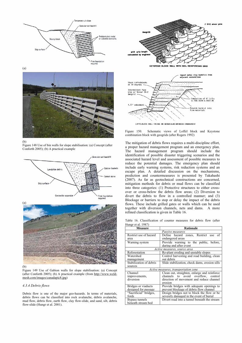
(a)
(b) Figure 148 Use of bin walls for slope stabilisation: (a) Concept (after Conforth 2005); (b) A practical example
(a)
(b) Figure 149 Use of Gabion walls for slope stabilisation: (a) Concept (after Conforth 2005); (b) A practical example (from http://www.weld-mesh.com/images/canadapic8.jpg)
4.3.4 Debris flows Debris flow is one of the major geo-hazards. In terms of materials, debris flows can be classified into rock avalanche, debris avalanche, mud flow, debris flow, earth flow, clay flow-slide, and sand, silt, debris flow-slide (Hungr et al. 2001).
Figure 150. Schematic views of Loffel block and Keystone combination block with geogrids (after Rogers 1992) The mitigation of debris flows requires a multi-discipline effort, a proper hazard management program and an emergency plan. The hazard management program should include the identification of possible disaster triggering scenarios and the associated hazard level and assessment of possible measures to reduce the potential damages. The emergency plan should include early warning systems, risk reduction systems and an escape plan. A detailed discussion on the mechanisms, prediction and countermeasures is presented by Takahashi (2007). As far as geotechnical constructions are concerned, mitigation methods for debris or mud flows can be classified into three categories: (1) Protective structures to either cross-over or cross-below the debris flow areas; (2) Diversion to divert the debris to flow in a controlled manner; and (3) Blockage or barriers to stop or delay the impact of the debris flows. These include grilled gates or walls which can be used together with diversion channels, nets and dams. A more refined classification is given in Table 16. Table 16. Classification of counter measures for debris flow (after Hungr et al. 1987)
Measure Rationale Passive measures
Restrict use of hazard area
Define hazard zones, Restrict use of endangered areas
Warning system Provide warning to the public, before, during and after event
Active measures, source area Reforestation Re-plant eroding and unstable slopesWatershed management
Control harvesting and road building, clean out debris
Stabilization of debris sources
Slide stabilization, check dams, erosion sills
Active measures, transportation zone Channel improvements, diversion
Clean out, straighten, enlarge and reinforce channels to avoid overflow, control direction of movement and reduce channel erosion
Bridges or viaducts designed for passage
Provide bridges with adequate openings to prevent blockage of debris flow channel
“Sacrificial” bridges, fords
Design bridges not to block the flow or be severely damaged in the event of burial
Bypass tunnels beneath stream bed
Divert road into a tunnel beneath the stream
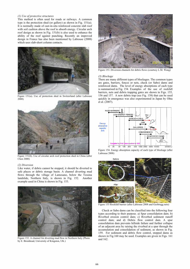
66
(1) Use of protective structures This method is often used for roads or railways. A common type is the protection shed (or gallery) as shown in Fig. 151(a). It is normally made of cast-in-situ reinforced concrete slab roof with soil cushion above the roof to absorb energy. Circular arch roof design as shown in Fig. 151(b) is also used to enhance the ability of the roof against punching. Recently an improved design in France has also been mentioned by Labiouse (2008) which uses slab-short column contacts.
Figure 151(a). Use of protection shed in Switzerland (after Labiouse 2008)
Figure 151(b). Use of circular arch roof protection shed in China (after Chen 2000) (2) Diversion Like water, if debris cannot be stopped, it should be diverted to safe places or debris storage basin. A channel diverting mud flows through the village of Lamosano, below the Tessina landslide, Northern Italy, is shown in Fig. 152. Another example used in China is shown in Fig. 153.
Figure 152. A channel for diverting mud flow in Northern Italy (Photo by E. Bromhead, University of Kingston, UK.)
Figure 153. Diversion channels for debris flows (courtesy L.M. Wang) (3) Blockage There are many different types of blockages. The common types are gates, barriers, fences or nets, check (or Sabo) dams and reinforced dams. The level of energy absorptions of each type is summarised in Fig. 154. Examples of the use of rockfall barriers, nets and debris trapping gates are shown in Figs. 155, 156 and 157. A new debris trap (see Fig. 158) that can be used quickly in emergence was also experimented in Japan by Ohta et al. (2007).
Figure 154. Energy absorption capacity of each type of blockage (after Labiouse 2008)
Figure 155 Rockfall barrier (after Labiouse 2008 and Geobrugg nets)
Check or Sabo dams can be classified into the following four types according to their purpose. a) Spur consolidation dam; b) Riverbed erosion control dam; c) Riverbed sediment runoff control dam; and d) Debris flow control dam. A spur consolidation dam prevents hillside failure and further collapse of an adjacent area by raising the riverbed at a spur through the accumulation and consolidation of sediment, as shown in Fig. 159. For sediment and debris flow control, stepped dams as shown in Fig.160 may be used. Examples are given in Figs. 161 and 162.

Figure 156 Use of net for the prevention of rockfall in China
Figure 157 Debris flow trap used in Japan
Figure 158 A new debris trap (after Ohta et al. 2007)
Figure 159 Use of spur consolidation dam for debris flow (after Nippon Koei 2007)
Figure 160 Use of stepped dam for debris flow (after Nippon Koei 2007)
Figure 161. A stepped dam used in China for the control of debris flow (courtesy of L.M. Wang)
Figure 162. Use of a combined debris barrier and stepped dams in China
An example of a reinforced dam for limiting the speed of a potential debris flow in the West Coast of Norway is given in Fig. 163.
Figure 163 Reinforced dam used for debris flow in Norway (source: NGI )

68
4.3.5 Case histories (1) Slope repair in Malaysia A repair of a landslide slope failure in Malaysia was reported by Ooi and Tee (2004). The 17 m high slope failure took place behind a hostel, as shown in Fig. 164. The failed slope was stabilized using soil nailed at 1.5 m intervals as the failed slope was being excavated to profile for the geogrid reinforced slope. Soil nails were necessary to provide the required factor of safety of 1.2 for temporary stage during the construction of the slope. Two levels of 3.6 m high geogrid reinforced vertical Keystone walls were used. The method of construction enables rapid building up of the walls without temporary forms.
Figure 164. Failed slope before repair (after Ooi and Tee 2004)
The slope rehabilitation scheme is presented in Fig. 165. A picture of the slope after repair is shown in Fig. 166. The Keystone walls also provided the support for the upper geogrid reinforced slope of 11.6 m high with slope angle of 46º. It carried the perimeter fencing and drainage at the top of the slope. The reinforcements used were Geogrid 160RE, 120RE, 80RE, 55RE, 40RE and SS20.
Figure 166. A picture of the repaired slope (after Ooi and Tee 2004)
Figure 165. Slope rehabilitation scheme involving soil nails, geogirds, keystone walls, drains etc (after Ooi and Tee 2004). (2) Road repair in Japan After the 2004 Niigataken-Chuetsu earthquake of a magnitude M6.8 in Japan, a railway embankment was damaged as shown in Fig. 167. The embankment was constructed in eroded depressions in the river terrace. The railway embankment was supported by a gravity-type soil retaining wall at its slope toe. The embankment totally failed for a length of about 90 m in the railway direction. The depth of the failure surface was about 7 m (Fig. 167). The repair of the highway was carried out within two months after failure using geosynthetic-reinforced soil retaining wall (GRS-RW) method as shown in Fig. 168 and
presented in details by Tatsuoka et al. (2007). The ground anchors were arranged to prevent a failure along inclined bedding planes in the surface weathered sedimentary soft rock layer (Fig. 168). The base ground for the GRS-RW was improved to a depth of 1 m by cement mixing with a cement weight of 150 kg/m3, which was then covered with a drainage layer consisting of crushed gravel. Geogrid reinforcement layers were arranged at a vertical spacing of 30 cm following the construction standard. A full height rigid facing of concrete with a thickness of 30 cm and 6.9 m high was subsequently constructed. Some construction processes are shown in Fig. 169.
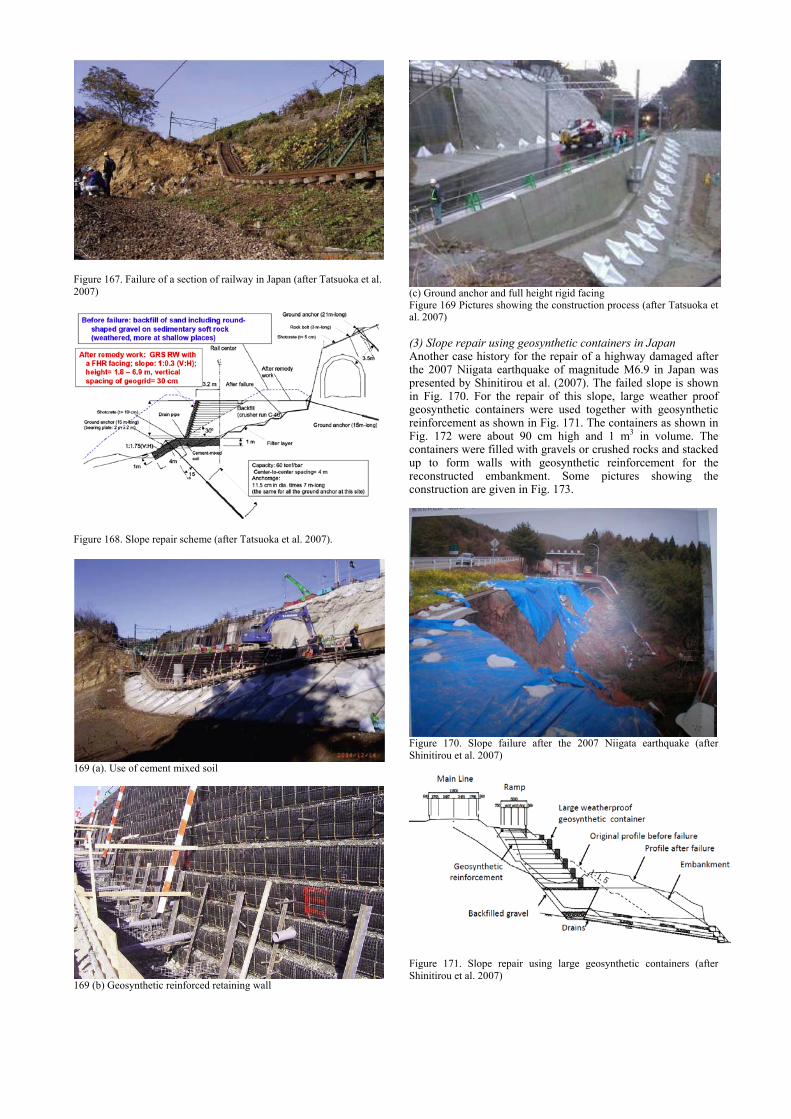
Figure 167. Failure of a section of railway in Japan (after Tatsuoka et al. 2007)
Figure 168. Slope repair scheme (after Tatsuoka et al. 2007).
169 (a). Use of cement mixed soil
169 (b) Geosynthetic reinforced retaining wall
(c) Ground anchor and full height rigid facing Figure 169 Pictures showing the construction process (after Tatsuoka et al. 2007) (3) Slope repair using geosynthetic containers in Japan Another case history for the repair of a highway damaged after the 2007 Niigata earthquake of magnitude M6.9 in Japan was presented by Shinitirou et al. (2007). The failed slope is shown in Fig. 170. For the repair of this slope, large weather proof geosynthetic containers were used together with geosynthetic reinforcement as shown in Fig. 171. The containers as shown in Fig. 172 were about 90 cm high and 1 m3 in volume. The containers were filled with gravels or crushed rocks and stacked up to form walls with geosynthetic reinforcement for the reconstructed embankment. Some pictures showing the construction are given in Fig. 173.
Figure 170. Slope failure after the 2007 Niigata earthquake (after Shinitirou et al. 2007)
Figure 171. Slope repair using large geosynthetic containers (after Shinitirou et al. 2007)
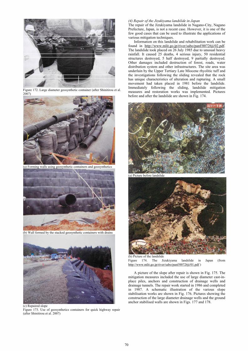
70
Figure 172. Large diameter geosynthetic container (after Shinitirou et al. 2007)
(a) Forming walls using geosynthetic containers and geosynthetics
(b) Wall formed by the stacked geosynthetic containers with drains
(c) Repaired slope Figure 173. Use of geosynthetics containers for quick highway repair (after Shinitirou et al. 2007)
(4) Repair of the Jizukiyama landslide in Japan The repair of the Jizukiyama landslide in Nagano-City, Nagano Prefecture, Japan, is not a recent case. However, it is one of the few good cases that can be used to illustrate the applications of various mitigation techniques.
Information on this landslide and rehabilitation work can be found in http://www.mlit.go.jp/river/sabo/panf/00726ji/02.pdf. The landslide took placed on 26 July 1985 due to unusual heavy rainfall. It caused 25 deaths, 4 serious injury, 50 residential structures destroyed, 5 half destroyed, 9 partially destroyed. Other damages included destruction of forest, roads, water distribution system and other infrastructures. The site area was underlain by the Upper Tertiary Late Miocene rhyolitic tuff and the investigations following the sliding revealed that the rock has unique characteristics of alteration and rupturing. A small movement had taken placed in 1981 before the landslide. Immediately following the sliding, landslide mitigation measures and restoration works was implemented. Pictures before and after the landslide are shown in Fig. 174.
(a) Picture before landslide
(b) Picture of the landslide Figure 174. The Jizukiyama landslide in Japan (from http://www.mlit.go.jp/river/sabo/panf/00726ji/01.pdf )
A picture of the slope after repair is shown in Fig. 175. The mitigation measures included the use of large diameter cast-in-place piles, anchors and construction of drainage wells and drainage tunnels. The repair work started in 1986 and completed in 1987. A schematic illustration of the various slope stabilisation works are shown in Fig. 176. Pictures showing the construction of the large diameter drainage wells and the ground anchor stabilised walls are shown in Figs. 177 and 178.

Figure 175. Picture of the repair slope (from http://www.mlit.go.jp/river/sabo/panf/00726ji/02.pdf)
Figure 176. Schematic illustration of the various slope stabilisation works (fromhttp://www.mlit.go.jp/river/sabo/panf/00726ji/15.pdf )
Figure 177. Drainage well constructed using reinforced concrete segments (from http://www.tuat.ac.jp/~sabo/lj/ljap4.htm ) 4.4 Mitigation against river or coastal related hazards
4.4.1 The types of failures
For mitigation against river and coastal related hazards, one of the major geotechnical concerns is the design and construction of hydraulic structures such as seawalls, breakwaters, sea dikes, river dikes and revetments. The failure of these structures may lead to catastrophic disasters, as in the case of the New Orleans flooding in 2005 due to Hurricane Katrina.
Figure 178. The repair of the Jizukiyama landslide in Japan (after http://www.tuat.ac.jp/~sabo/lj/ljfg50.htm )
The failure of hydraulic structures can be classified into the following four categories as shown in Table 17. The duties of a geotechnical engineer include not only the prevention of failures but also the rehabilitation of failed river or coastal protection structures after a disaster.
Table 17. Types of failures of hydraulic structures (with reference to Liu et al. 2004)
Categories Failure Mechanisms Hydraulic failure Overflow, overtopping, erosion of inner or
outer slope, erosion of foreshore, erosion of crest, erosion of inner toe of the dike, piping, and scour.
Geotechnical failure Overall stability of the dike, slip of inner or outer slope, liquefaction, settlement, and squeezing
Human factors Human errors, effects of buildings and trees, pipelines, and cable crossing
Unforeseen events or natural disasters
Ship collision, drifting ice, heavy storm, hurricane, tsunami, and earthquake.
4.4.2 Construction of river or coastal protection structures
The types of river or coastal protection structures can be summarized in Table 18. As illustrated in Figs. 179 to 183, the first three are conventional types and will not be elaborated in this report. Brief discussions on the rest will be made below. It should be mentioned that very often, more than one type of structures are adopted for dike construction, For example, compacted earth dikes can be used together with sheet pile walls as shown in Fig. 179b and geotextiles can be used to reduce the settlement and enhance the stability of a dike, see Fig. 57 of Section 2.5.6. Table 18. Classification of dikes and coastal structures according to materials used
Type Construction method Earth-fill dike or levee
1). Using compacted soils 2). Using cement mix soils or bagged soil 3). Using dumped rocks
Masonry and concrete
1). Using cast-in-place or precast concrete walls2). Using precast concrete panels 3). Using roller compacted concrete
Steel sheet piles or bored piles
1). Driven steel sheet pile wall 2). Contiguous bored pile or prefabricated sprung piles
Geotextile or geosynthetic materials
1). Geo-tube filled with concrete mortar, sand or clay2). Rubber dam 3). Geo-bag or geo-container 4). Geo-mattress
Prefabricated concrete segment
1). Concrete caissons 2). Semi-circular concrete caissons 3). Steel or concrete suction piles or caissons 4). Tongtu assembly method
Mix types Dike construction involving the use two or more of the above methods

72
(a). Dike made of compacted soil
(b) Dike made of steel-sheet piles
(c). Dike made of precast concrete wall Fig. 179. Flood protection structures used in the New Orleans area (after Mosher and Duncan 2007)
Figure 180. Dike made of bagged soils (after Xu et al 2008)
Fig 181. Concrete seawalls (After Dutta 2007)
(a)
Figure 182. Saluda Dam made of roller compacted concrete (a) Cross-section; (b) picture (after Bair and Koleber 2006)
Figure 183. Steel sheet piles used in Singapore (a) Cross-section (after Bo et al. 2005); (b) A picture
(a)

(1) Geotextile tubes (Geo-tubes), bags (Geo-bags), mattresses (Geo-mats), and containers (Geo-containers) The use of geosynthetic materials has offered many new options for hydraulic structure construction. Several methods have been developed to use geotextile materials for the construction of coastal structures such as breakwaters and dikes in the past decades. One of the methods is to use geotextiles acting as formwork for cement mortar units cast in situ (Silvester and Hsu 1993). The mortar mix need be only of sufficient compressive strength to support the weight above, plus the moment from the side force of the waves. Since the flexible membrane is required to hold the mixture in place until it sets, any subsequent deterioration due to UV rays or other conditions is of little concern. Thus, this method tends to be cheaper than conventional methods. Applications of the mortar filled geotextile tubes are illustrated in Fig. 184. Details can be referred to Silvester and Hsu (1993). Similar methods, but using sand or dehydrated soil as the fill material, have also been used for dike construction (Kazimierowicz 1994; Miki et al. 1996; Saathoff et al. 2007). Sand or sandy soil is the most ideal fill material for this purpose. For near shore or offshore projects, a suction dredger can be used to pump sand from the seabed or a sand pit directly into the geotextile tubes. In case sand is not readily available, silty clay or soft clay may also be used (Chu and Yan 2007). In this case, the clayey fill would have to be in a slurry state in order to be pumped and flow in the tube. The slurry fill would have to be dewatered in the geotextile bags or tubes under an ambient pressure. Then the selection of the geotextile used for the bags or tubes becomes important. The geotextile has to be chosen to meet both the strength and filter design criteria. Some analytical methods have been developed to estimate the required tensile strength for the geotextile (Kazimierowicz 1994; Miki et al. 1996; Leshchinsky et al. 1996). The apparent opening size (AOS) of the geotextile needs to be selected to allow the pore pressure to dissipate freely and yet retain the soil particles in the bags.
(a)
(b)
Figure 184 Use of geotextiles: (a) to replace core material and (b) to provide a space for core fill (After Silvester and Hsu, 1993)
When dikes or weirs are to be built across a river or a lake
for flood control and for creating a small reservoir, water or air filled rubber tubes have been used to form the so called rubber dam. The height of the inflated rubber tube ranges from 1 to 6 m. The advantage of a rubber dam is that there is no span limit. The longest dam built is more than 2 km. One example is shown in Fig. 185, which is 6 m high and 96 m long across the Qingjiang River in China. The rubber tube is prefabricated using high strength synthetics, such as macromolecule compound materials. The rubber tube can be inflated using either air or water. Normally a concrete base is required to anchor the rubber tube. The highest rubber dam in the world so far is the one used for the Ramspol storm surge barrier in Netherlands (see Fig. 186). It is 8.35 m high and is inflated by both water and air.
Figure 185. A 6m high rubber dam in China (after www.cnhubei.com)
(a). Cross-section of the rubber dam
Figure 186. The rubber dam used in the Ramspol storm surge barrier in Netherlands (after Inner Harbour Navigation Canal Floodgates Conceptual Study report 2007).
However, the rubber dams are only applicable to the construction of small dikes. For dikes more than 8 m high, geo-tubes, geo-bags, or geo-mats may be used. Examples of the use of geo-tubes and geo-bags as scour apron or breakwater are shown in Figs. 187 and 188. An example of the use of geo-mats for dike construction is shown in Fig. 189. In this example, clay slurry dredged from the seabed was used to fill the mats. The design of this dike is illustrated in Fig. 190 (Chu and Yan 2007). The cross-sectional dimension of the geo-mat changes with the design for the dike as shown in Fig. 190. The longitudinal length ranges from 20 to 30 m. The height of the geo-mat after consolidation is from 0.5 to 1.0 m. The bags were formed by sewing geotextile sheets using ordinary sewing machines. The geotextile used for the geo-mat was a woven geotextile of 131 g/m2. It had a thickness of 0.52 mm, AOS of 0.145 mm and longitudinal and transverse strength of 28 kN/m and 26 kN/m, respectively. The surface of the dike was covered by a concrete mattress which will be discussed in Section 4.4.3. For more details of this project, see Chu and Yan (2007).
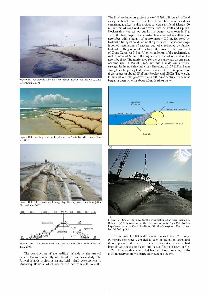
74
Figure 187. Geotextile tube and scour apron used in Sea Isle City, USA (after Dutta 2007)
Figure 188. Geo-bags used as breakwater in Australia (after Saathoff et al. 2007)
Figure 189. Dike constructed using clay filled geo-mats in China (after Chu and Yan 2007)
Figure. 190. Dike constructed using geo-mats in China (after Chu and Yan, 2007)
The construction of the artificial islands at the Amwaj
Islands, Bahrain, is briefly introduced here as a case study. The Amwaj Islands project is an artificial island development in Muharraq, Bahrain, which was carried out from 2003 to 2006.
The land reclamation project created 2.798 million m² of land along a beachfront of 9.5 km. Geo-tubes were used as containment dikes in this project to create artificial islands. 20 million m³ of sand and stone were used as infill and rip rap. Reclamation was carried out in two stages. As shown in Fig. 191a, the first stage of the construction involved installation of geo-tubes with a height of approximately 2.6 m, followed by hydraulic filling of sand behind the geo-tubes. The second stage involved installation of another geo-tube, followed by further hydraulic filling of sand to achieve the finished platform level of Chart Datum of 3.6 m. Upon completion of the reclamation, rock armour of 60 to 300 kilogram was placed in front of the geo-tube dike. The fabric used for the geo-tube had an apparent opening size (AOS) of 0.425 mm and a wide width tensile strength in the machine and cross directions of 175 kN/m. Seam strength in the principle directions was about 50 to 60 percent of these values or about105 kN/m (Fowler et al. 2002). The weight to area ratio of the geotextile was 948 g/m2 geotube placement began in open water in about 1.0 m depth of water.
MHWN = CD+2.2m
Geolon PP80L
Armour rock60 - 300 kg
3h:1v
Platform level = CD+3.6m
Sea bed level = CD-1.6m
Geotube
Geotextile
(a)
(b) Figure 191. Use of geo-tubes for the construction of artificial islands in Bahrain: (a) Schematic view; (b) Construction (after Ten Cate Niclon http://www.hastex.net/webfiles/HastexNL/files/Geosytems_Case_Histories_Feb2005.pdf )
The geotube lay flat width was 6.5 m wide and 97 m long.
Polypropylene ropes were tied to each of the nylon straps and these ropes were then tied to 10 cm diameter steel posts that had been driven about one meter into the sea floor as shown in Fig. 192a. The geo-tubes were filled from a fill opening (Fig. 192b) at 50 m intervals from a barge as shown in Fig. 193.

(a)
(b) Figure 192 (a) Geotube with anchor poles and ropes prior to filling (b) during filling (after Fowler et al. 2002)
Figure 193 Method for filling the geo-tube underwater (after Fowler et al. 2002)
Submerged reef breakwaters as shown in Fig. 194 were constructed to create artificial beaches and to reduce erosion. The length of the breakwaters, Lr, was 300 m, the gap between the breakwaters, G, was 0.25 times Lr or about 75 m. The distance offshore is X = Lr = 300 m. The distance to the beach shoreline is about 340 m from the hard boundary of the island.
Geo-tubes have also been used effectively for preventing sea bank from erosion and for subsurface dune restoration. One case study in Florida, USA, is presented by Advanced Coastal Technologies. One condominium along Vero Beach, Florida, USA, was protected by a revetment structure consisting of 14 layers of sand filled geo-tubes placed on a natural dune slope of 1V:3H, as shown in Fig. 195. This revetment has been proved effective during the Hurricane Francis in Sept 2004. This can be seen from the comparison of the bird’s eye view pictures taken before and after the Hurricane as shown in Fig. 196. As pointed by the arrow in Fig. 196b, only the green and the space behind this revetment survived. The greens and beaches in front of the other buildings were all destroyed (see Fig. 196b).
Figure 194 Design of submerged reef breakwater (after Fowler et al. 2002)
Figure 195. Use of geo-tubes for beach protection and surface dune restoration in Florida (after Advanced Coastal Technologies, www.advancedcoastaltechnology.com/studies.html )
(a)
(b) Figure 196. Comparison of the Vero Beach, Florida, (a) Before Hurricane; (b) After Hurricane (after www.advancedcoastaltechnology.com/studies.html) .
Another similar method in Holland and other countries is
the geo-container (Nicolon 1988; Fowler 1995). This method has been used for construction of dikes, underwater berms, stabilisation of underwater banks, shoreline protection, and disposal of contaminated dredged materials (Pilarcyzk 2000). As illustrated in Fig. 197, dredged or excavated materials are hydraulically or mechanically placed in a geotextile liner

76
installed in a specially designed bottom open barge. When soil is filled up to 80% of the holding capacity, the liner is sealed and sewn together using handy sewing machine and stranded high-tensile thread and fastened by ropes. The geo-container is then dropped to the seabed by opening the bottom of the barge. The volume of the geo-container varies from 100 to 1000 m3. The construction process is illustrated in Fig. 198. Two typical applications of the geo-container are shown in Fig. 199.
Figure 197. Filling and placing process for geo-container (after Pilarcyzk 2000)
(a)
(b)
(c) Figure 198. Filling and sealing process for geo-container (after http://www.geostk.ru/eng/)
(a)
(b) Figure 199. Examples of application of geo-containers in dike construction of bank protection (after www.bumatech.com/.../geocontainer/) (2) Precast concrete segments Dikes or breakwater can be constructed using precast concrete segments as shown in Fig. 200. The precast concrete segment can be towed to the required location and sunk by filling it with water or soil, as shown in Fig. 200. This construction method is relatively fast and is suitable for quick installation of seawalls or breakwaters on relatively firm seabed or for the repair of damaged seaport. For the construction of breakwater,
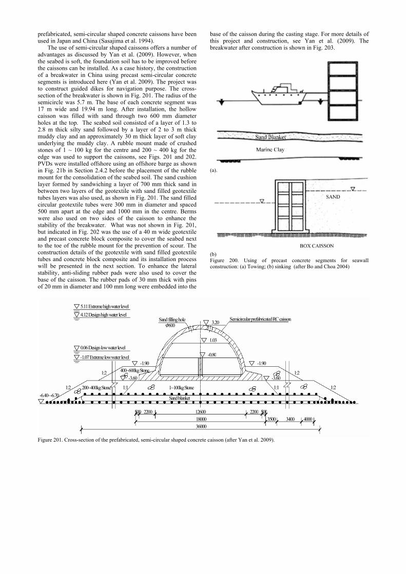
prefabricated, semi-circular shaped concrete caissons have been used in Japan and China (Sasajima et al. 1994).
The use of semi-circular shaped caissons offers a number of advantages as discussed by Yan et al. (2009). However, when the seabed is soft, the foundation soil has to be improved before the caissons can be installed. As a case history, the construction of a breakwater in China using precast semi-circular concrete segments is introduced here (Yan et al. 2009). The project was to construct guided dikes for navigation purpose. The cross-section of the breakwater is shown in Fig. 201. The radius of the semicircle was 5.7 m. The base of each concrete segment was 17 m wide and 19.94 m long. After installation, the hollow caisson was filled with sand through two 600 mm diameter holes at the top. The seabed soil consisted of a layer of 1.3 to 2.8 m thick silty sand followed by a layer of 2 to 3 m thick muddy clay and an approximately 30 m thick layer of soft clay underlying the muddy clay. A rubble mount made of crushed stones of 1 ~ 100 kg for the centre and 200 ~ 400 kg for the edge was used to support the caissons, see Figs. 201 and 202. PVDs were installed offshore using an offshore barge as shown in Fig. 21b in Section 2.4.2 before the placement of the rubble mount for the consolidation of the seabed soil. The sand cushion layer formed by sandwiching a layer of 700 mm thick sand in between two layers of the geotextile with sand filled geotextile tubes layers was also used, as shown in Fig. 201. The sand filled circular geotextile tubes were 300 mm in diameter and spaced 500 mm apart at the edge and 1000 mm in the centre. Berms were also used on two sides of the caisson to enhance the stability of the breakwater. What was not shown in Fig. 201, but indicated in Fig. 202 was the use of a 40 m wide geotextile and precast concrete block composite to cover the seabed next to the toe of the rubble mount for the prevention of scour. The construction details of the geotextile with sand filled geotextile tubes and concrete block composite and its installation process will be presented in the next section. To enhance the lateral stability, anti-sliding rubber pads were also used to cover the base of the caisson. The rubber pads of 30 mm thick with pins of 20 mm in diameter and 100 mm long were embedded into the
base of the caisson during the casting stage. For more details of this project and construction, see Yan et al. (2009). The breakwater after construction is shown in Fig. 203.
(a).
(b) Figure 200. Using of precast concrete segments for seawall construction: (a) Towing; (b) sinking (after Bo and Choa 2004)
5.11 Extreme high water level 4.12 Design high water level
0.06 Design low water level
-1.07 Extreme low water level
Sand filling hole Φ600
Semicircular prefabricated RC caisson
1.03
-0.80
3.20
-1.90
-6.40~-6.70 1~100kg Stone
Sand blanket
500 2200 12600 2200 50018000 3500 3400 4000 36000
1:2
1:1 1:2 1:2
1:2
1:1
-1.90
-3.60 -3.60
200~400kg Stone
400~600kg Stone
Figure 201. Cross-section of the prefabricated, semi-circular shaped concrete caisson (after Yan et al. 2009).

78
Figure 202. Illustration of the prefabricated caisson supported by a rubble amount and scour protection cover
Figure 203. Breakwater made of caisson boxes (3) Steel or concrete suction piles or caissons One of the disadvantages of the prefabricated concerte caisson method as described above is the need to treat the soft seabed soil and the construction of rubble mount which can be time consuming. Thus, the gravity caisson method is not suitable for disaster mitigation purposes.
Another method of building breakwater or seawalls is the use of cylindrical steel or concrete suction piles or caissons. This method is particularly suitable to the construction of breakwater on soft seabed or in deep water. Suction piles or caissons are sunk into seabed using a huge suction (hundreds of tonnes) until sufficient bearing capacity is obtained. Thus
excavation or improvement of soft seafloor is not necessary for the installation of piles or caissons. Seawalls or breakwater can be built on top of the piles or caissons.
This method has been used in China in a breakwater project recently. Four 12 m in diameter reinforced concrete or steel cylinders were connected together using 4 walls as one unit as shown in Fig. 204a. The unit formed by the four steel cylinders was sunk into soft seabed soil using suction. The top opening of the four cylinders was covered by a precast concrete plate with two circular concrete beams of 0.5 m tall. Fitting the beams were two prefabricated concrete cylinders of 12 m in diameter, as shown in Fig. 204b. The cross-section of the breakwater is shown in Fig. 205. The installation of the lower 4 cylinder unit and the upper cylinders are shown presented in Fig. 206.
(a). Viewing from the bottom of the suction caissons
(b) Viewing from the top of the concrete suction caissons with the top cylinders used as part of the breakwater Figure 204. Layout of the suction caissons (courtesy S.W. Yan)
Fig. 205 Cross-section of the breakwater built using prefabricated cylinders (courtesy S.W. Yan)
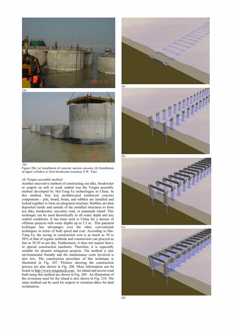
(a)
(b) Figure 206. (a) Installation of concrete suction caissons; (b) Installation of upper cylinders to form breakwater (courtesy S.W. Yan) (4) Tongtu assembly method Another innovative method of constructing sea dike, breakwater or seaport on soft or weak seabed was the Tongtu assembly method developed by Hai-Tong-Tu technologies in China. In this method, four key prefabricated reinforced concrete components - pile, board, beam, and rubbles are installed and locked together to form an integrated structure. Rubbles are then deposited inside and outside of the installed structures to form sea dike, breakwater, sea-entry road, or manmade island. This technique can be used theoretically in all water depth and any seabed conditions. It has been used in China for a dozens of offshore projects with water depths up to 5.5 m. This patented technique has advantages over the other conventional techniques in terms of both speed and cost. According to Hai-Tong-Tu, the saving in construction cost is as much as 30 to 50% of that of regular methods and construction can proceed as fast as 30-50 m per day. Furthermore, it does not require heavy or special construction machines. Therefore, it is especially suitable for disaster mitigation projects. The method is also environmental friendly and the maintenance costs involved is also low. The construction procedure of this technique is illustrated in Fig. 207. Pictures showing the construction process are also shown in Fig. 208. More information can be found in http://www.tongtutech.com/. An island and access road built using this method are shown in Fig. 209. An illustration of the revetment used for the island is also shown in Fig. 210. The same method can be used for seaport or retention dikes for land reclamation.
(a)
(b)
(c)
(d)
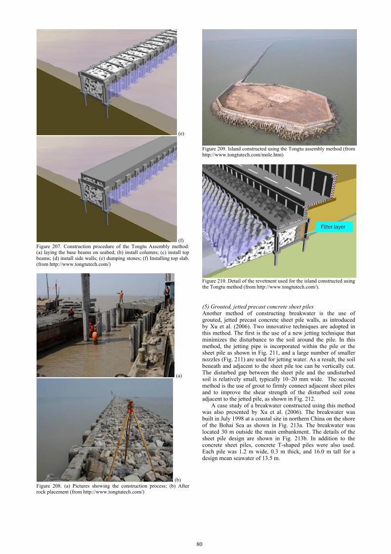
80
(e)
(f) Figure 207. Construction procedure of the Tongtu Assembly method: (a) laying the base beams on seabed; (b) install columns; (c) install top beams; (d) install side walls; (e) dumping stones; (f) Installing top slab. (from http://www.tongtutech.com/)
(a)
(b) Figure 208. (a) Pictures showing the construction process; (b) After rock placement (from http://www.tongtutech.com/)
Figure 209. Island constructed using the Tongtu assembly method (from http://www.tongtutech.com/mole.htm)
Figure 210. Detail of the revetment used for the island constructed using the Tongtu method (from http://www.tongtutech.com/). (5) Grouted, jetted precast concrete sheet piles Another method of constructing breakwater is the use of grouted, jetted precast concrete sheet pile walls, as introduced by Xu et al. (2006). Two innovative techniques are adopted in this method. The first is the use of a new jetting technique that minimizes the disturbance to the soil around the pile. In this method, the jetting pipe is incorporated within the pile or the sheet pile as shown in Fig. 211, and a large number of smaller nozzles (Fig. 211) are used for jetting water. As a result, the soil beneath and adjacent to the sheet pile toe can be vertically cut. The disturbed gap between the sheet pile and the undisturbed soil is relatively small, typically 10–20 mm wide. The second method is the use of grout to firmly connect adjacent sheet piles and to improve the shear strength of the disturbed soil zone adjacent to the jetted pile, as shown in Fig. 212.
A case study of a breakwater constructed using this method was also presented by Xu et al. (2006). The breakwater was built in July 1998 at a coastal site in northern China on the shore of the Bohai Sea as shown in Fig. 213a. The breakwater was located 30 m outside the main embankment. The details of the sheet pile design are shown in Fig. 213b. In addition to the concrete sheet piles, concrete T-shaped piles were also used. Each pile was 1.2 m wide, 0.3 m thick, and 16.0 m tall for a design mean seawater of 13.5 m.

(a)
(b) Figure 211 New jetted precast concrete sheet pile with preinstalled small nozzles (after Xu et al. 2006)
(a)
(b) Figure 212. Schematic illustration of the installation of jetted precast concrete sheet piles and the detail of the joints that can be grouted (after Xu et al. 2006)
(a) A picture of the dike
(b) Cross-section of the dike Figure 213. Design and construction of a breakwater made of jetted precast concrete sheet piles (After Xu et al. 2006)
4.4.3 River or sea bank or bed protection methods
Heavy storms such as hurricanes or cyclones can cause severe erosion or damage to the river or sea bank. Dikes need to be armoured by resurfacing them with protective non-erodible materials. The types of coastal dike and riverbank protection systems are summarised in Table 19. Examples of conventional bank protection methods are shown in Figs. 214 to 222. A few other less commonly used methods are described as follows.

82
Table 19 Classification of river bank or coastal protection methods according to materials used
Type Construction Method Rock, gravels or other earth materials
1). Riprap or dumped stone 2). Grouted (mortared) riprap 3). Asphalt or cement mixed soil.
Concrete 1). Concrete cover or concrete mattress;2). Concrete grid or interlocking angular concrete blocks; 3). Chained concrete blocks or concrete girds 4). Cast-in-situ concrete mattress 5). Precast concrete armors 6). Concrete piles or columns 7). Shotcrete
Geotextile including metal, wood or other products
1). Gabion mattress or 2). Geonet cages 3). Geotextile composites 4). Geotextile tube, bag or containers 5). Sheet piles
Natural materials 1). Use of bamboo, willows and other natural materials 2). Use of vegetations
Figure 214. Riprap used for sea revetment in Singapore (b) Figure 215. Grouted stones for river bank in China (after Liu et al. 2006)
Figure 216. Asphalt cover for riverbank in Bangladesh (From http://www.citechco.net/jmba/ )
Figure 217. Concrete cover used for sea dike in Vietnam Figure 218. Cast-in-situ concrete mattress for river bank in China Figure 218. concrete mattress used in China (after Liu et al. 2004) Figure 219. Vegetation for river bank in China (after Liu et al. 2006)
Figure 220.Use of Armours (from http://serumpun.com )
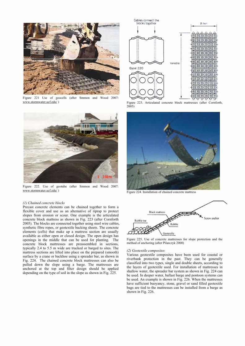
Figure 221 Use of geocells (after Smmon and Wood 2007: www.stormwater.ucf.edu/ )
Figure 222. Use of geotube (after Smmon and Wood 2007: www.stormwater.ucf.edu/ ) (1) Chained concrete blocks Precast concrete elements can be chained together to form a flexible cover and use as an alternative of riprap to protect slopes from erosion or scour. One example is the articulated concrete block mattress as shown in Fig. 223 (after Cornforth 2005). The blocks are connected together using steel wire cables, synthetic fibre ropes, or geotextile backing sheets. The concrete elements (cells) that make up a mattress section are usually available as either open or closed design. The open design has openings in the middle that can be used for planting. The concrete block mattresses are preassembled in sections, typically 2.4 to 5.5 m wide are trucked or barged to sites. The mattress sections are lifted into place on the prepared (smooth) surface by a crane or backhoe using a spreader bar, as shown in Fig. 224. The chained concrete block mattresses can also be pulled down the slope using a barge. The mattresses are anchored at the top and filter design should be applied depending on the type of soil in the slope as shown in Fig. 225.
Figure 223. Articulated concrete block mattresses (after Cornforth, 2005)
Figure 224. Installation of chained concrete mattress
Figure 225. Use of concrete mattresses for slope protection and the method of anchoring (after Pilarczyk 2000) (2) Geotextile composites Various geotextile composites have been used for coastal or riverbank protection in the past. They can be generally classified into two types, single and double sheets, according to the layers of geotextile used. For installation of mattresses in shallow water, the spreader bar system as shown in Fig. 224 can be used. In deeper water, ballast barge and pontoon systems can be used. An example is shown in Fig. 226. When the mattresses have sufficient buoyancy, stone, gravel or sand filled geotextile bags are tied to the mattresses can be installed from a barge as shown in Fig. 226.

84
Figure 226 Geotextile composite used for costal or riverbank protection in China (after SETC 2000 )
Figure 227. Installation of geotextile and concrete block composite (after Yan et al. 2009) A type of geotextile and concrete block composite has been used for the breakwater construction in Shanghai, China. A 40 m wide geotextile and precast concrete block composite was used to cover the seabed outside the toe of the rubble mount that faced the open sea for the prevention of scour. The geotextile and concrete block composite and its installation process are shown in Fig. 227. The concrete blocks were 400 mm x 400 mm in square and 160 mm thick. They were chained together to form a mat which was put on to the geotextile sheet to form a composite (Yan et al. 2006). For the same project, a mattress consisting of geotextile and sand fill tubes as shown in Fig. 228 has also been used as a reinforcement layer between the rubble mount and the soft seabed soil (see Fig. 201). The tubes were formed during installation by filling sand into 300 mm diameter geotextile tubes from a barge before the geotextile and sand tube composite were placed, as shown in Fig. 228. The tubes were spaced at a distance of 500 to 1000 mm which gave the gravity for the geotextile to sink onto the seabed. (3) Gabion Mattresses Gabion mattresses are formed by connecting rock filled Gabion baskets together. They are normally fabricated on site. An example of its use for underwater slope is shown in Fig. 229. The design and use of Gabion mattresses for revetment have been described in FHWA (1989). For shallow water installations, the mattress units can be placed by a crane using a lifting frame, or the units are filled individually on the shoreline and dragged down the slope into water as shown in Fig. 230. In deep water, a barge or pontoon is used to place the mattress (see Fig. 231). A gabion tube is also reported to be used as shown in Fig. 232.
Figure 228 Geotextile with sand filled tubes for erosion and scour control (after Yan et al. 2009)
Figure 229 Use of Gabion mattresses on slope, gabion baskets at toe with apron mattress (after Cornforth, 2005).
Figure 230 Underwater placement of gabion mattresses (a), (b) and (c) in shallow water (after Cornforth 2005)
Figure 231 Placement of gabion mattresses in deep water from a barge or pontoon (after Cornforth 2005)

Figure 232. A gabion tube used for shore protection (After John 1987)
Rock filled gabions have also been used in the levee rehabilitation work after Hurricane Katrina in New Orleans as shown in Fig. 233.
Figure 233 Use of rock filled gabions for levee rehabilitation at New Orleans (after Briaud et al. 2008) (4) Concrete mattresses The slope of a dike can be protected by a cast-in-place concrete mattress. It is formed by pumping lean concrete into a mould made of geotextile. During the filling, mixing water is squeezed out through the permeable fabric and result in a significant reduction in the water-cement ratio of the grout. Once the concrete hardens, a rigid or semi-rigid cover which forms the contour of the slope is created. A picture showing the dike covered by the cast-in-place concrete layer is given in Fig. 234.
Figure 234. Use of cast-in-place concrete mattress for bank protection
The concrete mattresses can be cast in different patterns as shown in Fig. 235. According to Pilarczyk (2000), a typical injection mix consists of 475 kg per m3 of cement , 1250 kg per m3 of sand, 325 kg per/ m3 of water and air (as much as required). The ratios used in China are: cement:sand = 1:2.56 to 1:3.08; cement:stone = 1:2.09 to 1:2.52; and water:cement = 0.65. The size of the stone should be less than 25 mm. The slump ratio is controlled at 21 ± 2 cm. The amount of cement used is between 308 to 350 kg per m3 (Bao et al. 1994). The slope of the bank should be no larger than 1.5H:1V. One
example of the design of the concrete mattress is shown in Fig. 236. Concrete mattresses can also be used to protect bridge piers from scouring as shown in Fig. 237.
Figure 235 Different patterns of concrete mattresses (after Pilarczyk 2000)
Figure 236 A concrete blanket is cast in-situ with geotextile as a mould to cover the dike (after SETC 2000).
Figure 237 Use of concrete mattresses to prevent the scour of bridge piers (after Fang 2007) (5) Geo-bags, geo-tubes or geo-containers Geo-bags or geo-tubes can also be used for bank protection. One example is shown in Fig. 238 in which sand filled geo containers of 0.75 m3 is used as revetment in the Coast of Queensland, Australia. Another example is shown in Fig. 239 for a river bank repair in China. The geo-tubes can also be connected together to form a mattress for seabed scour protection in a way similar to that shown in Fig. 228. One such an example is given in Fig. 240 where a mattress formed by geo-tubes is placed into the sea from a barge.
(a)

86
Fig. 238. Revetment made of sand-filled geotextile containers (after Saathoff et al. 2007)
Figure 239. Sand filled geotextitle bags are used for river bank repair (after SETC 2000)
Figure 240. Placement of mattress formed by geo-tubes (after SETC 2000) (6) Use of natural materials Natural materials have been used for river bank or sea dike protection for thousands of years. One example is the Tujiangyan dam in China which was constructed in 256 BC in Sichuan and is currently still in use. Part of the construction process as envisaged by an artist is shown in Fig. 241. The use of willow mats for the protection of the Mississippi River bank in USA is also shown in Fig. 242. A similar method, the so-called fascine mattress (John 1987; Saathoff 2003) has also been used for a long time in Holland and other countries. Other types that have been used in the Dutch Delta Works Project are fixtone mattress, block mattress and granular mattress. The details are described in John (1987).
Figure 241. Use of timbers and other natural materials for the Tujiangyan dam hydraulic system in Sichuan, China (from http://blog.163.com/)
Figure 242. Placing willow mats by loading them with rock to prevent scour along Upper Mississippi River in probably 1890. (from http://wiki.cincinnatilibrary.org/index.php/)
One of those traditional fascine methods was applied to a Mekong riverbank protection project in Lao in 2005 by Japan. Using wood and tree branches collected in mountains near villages, mats were made and sunk down to the river bottom as shown in Fig. 243. This method made possible a large-scale river bank protection with low costs. Moreover, the mats provided habitats for aquatic organisms such as small fish and bottom animals. Thus, the method was also environmentally-friendly.
Figure 243. Use of wood and tree branches for river bank protection (from http://www.mofa.go.jp/POLICY/oda/white/2006/ODA2006/ html /column/cl02003.htm)
Another fascine mattress application is shown in Fig. 244. As shown, bamboos or round-woods are tied to a geotextile fabric sheet at 1 m spacing in a latticework making the whole structure semi-stiff. After stones are placed the mattress lays down flat on the bed. The fascines have the advantage of trapping the rocks thus holding them in position and preventing them from rolling down the slope.

Figure 244. Use of bamboo and geotextile composite for river bank protection (from Shercliff 2005)
Vegetations can be used as part of the bank protection system. One example is shown in Fig. 245. For more information, see Pilarczyk (2000).
Fig. 245 Use of vegetations for river bank protection (after Pilarczyk 2000)
4.4.4 Mitigation methods for prevention of imminent disasters
The types of failures of hydraulic structures have been given in Table 16. The mitigation methods for different types of failure are summarized in Table 20. Owing to page limitation, only some of these methods for the prevention of eminent disasters will be discussed in the following. Table 20 Mitigation Methods for different types of failure
Type Methods Overtopping Geobags, Sheetpiles, Concrete wall, New earth fillSeepage and piping
Impermeable sheets, Seepage piloting, Weight filter, Cofferdam, vertical impermeable barrier, Sand berm
Slope protection Geotextile sheet Leakage hole Iron-pot, geomembane sheet, cofferdam-well filter,
grouting Dike Stability Refilling, berms, piles, grouting Erosion Gabions, soil bags, mattresses, sheet piles,
additional dike bodies, spur Breach Ship sinking; closure dike, soil bags. (1) Overtopping One observation made from the failures caused by Hurricane Katrina is that “no levee failures occurred without overtopping” (Sills et al. 2008). One of the consequences of overtopping is erosion of the downstream embankment slope which may cause the collapse of the dike. When a dike has to be elevated to prevent an eminent overtopping, one of the most common methods is to use earth filled bags. These bags can be made of natural products such as straw and jute or geosynthetics. They can be prefilled and thus deployed quickly. As an example, one method proposed by Mohri et al. (2008) for the rehabilitation of old earth dams is introduced here. Shown in Fig. 246, the downstream slope of an earth-fill dam is protected using soil
bags anchored with geosynthetic reinforcement layers arranged inside the slope.
Figure 246. Use of soil bags for the prevention of overtopping for earth dams (after Mohri et al. 2008)
Another method is to form a cofferdam shown in Fig. 247a using timber or steel sheetpiles as columns and timber logging, bamboo mats, or geotextile net in-between the piles to form two rows of walls. Crushed stones or compacted soils are used to fill in the gap between the two walls. The piles should be tied together using metal wire to enhance the stability of the cofferdam. When the height required is only 1 to 2 m, single row of piles and timber logging may also be used and supported with backfilled earth, as shown in Fig. 247b.
(a) Double sheetpiles made of timber
(b) Timber sheetpiles Figure 247. Methods for elevation of dikes to prevent overtopping (after Dong 1998) (2) Seepage through dike or piping through foundation soil When a large amount of seepage through a dike is identified, the repair can be done by blocking the holes or cavities along the upstream and/or providing additional drainage along the downstream. For the former, grouting is commonly used, though other methods have also been used. For the upstream, geotextile and sand filled bags are used to block holes or cavities in the embankment or prevent them from expanding, see Fig. 248a. For the downstream, geotextile and drainage blanket are used to improve drainage, lower down the phreatic line and reduce erosions, see. Fig. 248b.
Figure 248a Use of geobags for the mitigation of piping (after Liu et al. 2004)
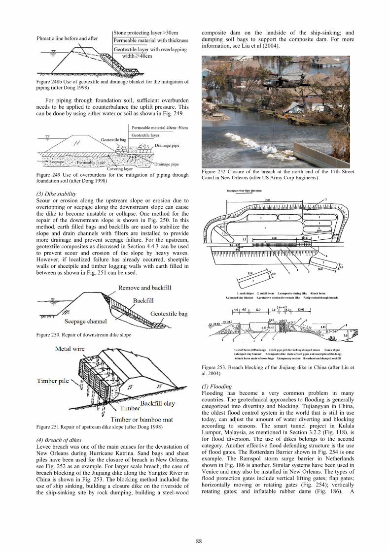
88
Figure 248b Use of geotextile and drainage blanket for the mitigation of piping (after Dong 1998)
For piping through foundation soil, sufficient overburden
needs to be applied to counterbalance the uplift pressure. This can be done by using either water or soil as shown in Fig. 249.
Figure 249 Use of overburdens for the mitigation of piping through foundation soil (after Dong 1998) (3) Dike stability Scour or erosion along the upstream slope or erosion due to overtopping or seepage along the downstream slope can cause the dike to become unstable or collapse. One method for the repair of the downstream slope is shown in Fig. 250. In this method, earth filled bags and backfills are used to stabilize the slope and drain channels with filters are installed to provide more drainage and prevent seepage failure. For the upstream, geotextile composites as discussed in Section 4.4.3 can be used to prevent scour and erosion of the slope by heavy waves. However, if localized failure has already occurred, sheetpile walls or sheetpile and timber logging walls with earth filled in between as shown in Fig. 251 can be used.
Figure 250. Repair of downstream dike slope
Figure 251 Repair of upstream dike slope (after Dong 1998) (4) Breach of dikes Levee breach was one of the main causes for the devastation of New Orleans during Hurricane Katrina. Sand bags and sheet piles have been used for the closure of breach in New Orleans, see Fig. 252 as an example. For larger scale breach, the case of breach blocking of the Jiujiang dike along the Yangtze River in China is shown in Fig. 253. The blocking method included the use of ship sinking, building a closure dike on the riverside of the ship-sinking site by rock dumping, building a steel-wood
composite dam on the landside of the ship-sinking; and dumping soil bags to support the composite dam. For more information, see Liu et al (2004).
Figure 252 Closure of the breach at the north end of the 17th Street Canal in New Orleans (after US Army Corp Engineers)
Figure 253. Breach blocking of the Jiujiang dike in China (after Liu et al. 2004) (5) Flooding Flooding has become a very common problem in many countries. The geotechnical approaches to flooding is generally categorized into diverting and blocking. Tujiangyan in China, the oldest flood control system in the world that is still in use today, can adjust the amount of water diverting and blocking according to seasons. The smart tunnel project in Kulala Lumpur, Malaysia, as mentioned in Section 3.2.2 (Fig. 118), is for flood diversion. The use of dikes belongs to the second category. Another effective flood defending structure is the use of flood gates. The Rotterdam Barrier shown in Fig. 254 is one example. The Ramspol storm surge barrier in Netherlands shown in Fig. 186 is another. Similar systems have been used in Venice and may also be installed in New Orleans. The types of flood protection gates include vertical lifting gates; flap gates; horizontally moving or rotating gates (Fig. 254); vertically rotating gates; and inflatable rubber dams (Fig. 186). A
Phreatic line before and after
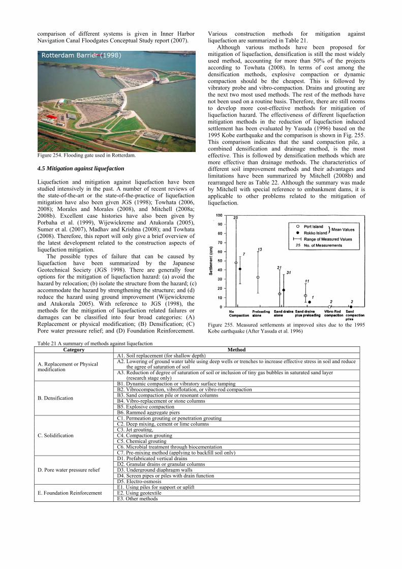
comparison of different systems is given in Inner Harbor Navigation Canal Floodgates Conceptual Study report (2007).
Figure 254. Flooding gate used in Rotterdam.
4.5 Mitigation against liquefaction
Liquefaction and mitigation against liquefaction have been studied intensively in the past. A number of recent reviews of the state-of-the-art or the state-of-the-practice of liquefaction mitigation have also been given JGS (1998); Towhata (2006, 2008); Morales and Morales (2008), and Mitchell (2008a; 2008b). Excellent case histories have also been given by Porbaha et al. (1999), Wijewickreme and Atukorala (2005), Sumer et al. (2007), Madhav and Krishna (2008); and Towhata (2008). Therefore, this report will only give a brief overview of the latest development related to the construction aspects of liquefaction mitigation.
The possible types of failure that can be caused by liquefaction have been summarized by the Japanese Geotechnical Society (JGS 1998). There are generally four options for the mitigation of liquefaction hazard: (a) avoid the hazard by relocation; (b) isolate the structure from the hazard; (c) accommodate the hazard by strengthening the structure; and (d) reduce the hazard using ground improvement (Wijewickreme and Atukorala 2005). With reference to JGS (1998), the methods for the mitigation of liquefaction related failures or damages can be classified into four broad categories: (A) Replacement or physical modification; (B) Densification; (C) Pore water pressure relief; and (D) Foundation Reinforcement.
Various construction methods for mitigation against liquefaction are summarized in Table 21.
Although various methods have been proposed for mitigation of liquefaction, densification is still the most widely used method, accounting for more than 50% of the projects according to Towhata (2008). In terms of cost among the densification methods, explosive compaction or dynamic compaction should be the cheapest. This is followed by vibratory probe and vibro-compaction. Drains and grouting are the next two most used methods. The rest of the methods have not been used on a routine basis. Therefore, there are still rooms to develop more cost-effective methods for mitigation of liquefaction hazard. The effectiveness of different liquefaction mitigation methods in the reduction of liquefaction induced settlement has been evaluated by Yasuda (1996) based on the 1995 Kobe earthquake and the comparison is shown in Fig. 255. This comparison indicates that the sand compaction pile, a combined densification and drainage method, is the most effective. This is followed by densification methods which are more effective than drainage methods. The characteristics of different soil improvement methods and their advantages and limitations have been summarized by Mitchell (2008b) and rearranged here as Table 22. Although the summary was made by Mitchell with special reference to embankment dams, it is applicable to other problems related to the mitigation of liquefaction.
Figure 255. Measured settlements at improved sites due to the 1995 Kobe earthquake (After Yasuda et al. 1996)
Table 21 A summary of methods against liquefaction
Category Method
A. Replacement or Physical modification
A1. Soil replacement (for shallow depth)A2. Lowering of ground water table using deep wells or trenches to increase effective stress in soil and reduce the agree of saturation of soilA3. Reduction of degree of saturation of soil or inclusion of tiny gas bubbles in saturated sand layer (research stage only)
B. Densification
B1. Dynamic compaction or vibratory surface tamping B2. Vibrocompaction, vibroflotation, or vibro-rod compactionB3. Sand compaction pile or resonant columnsB4. Vibro-replacement or stone columnsB5. Explosive compactionB6. Rammed aggregate piers
C. Solidification
C1. Permeation grouting or penetration grouting C2. Deep mixing, cement or lime columnsC3. Jet grouting, C4. Compaction groutingC5. Chemical groutingC6. Microbial treatment through biocementationC7. Pre-mixing method (applying to backfill soil only)
D. Pore water pressure relief
D1. Prefabricated vertical drains D2. Granular drains or granular columnsD3. Underground diaphragm wallsD4. Screen pipes or piles with drain functionD5. Electro-osmosis
E. Foundation Reinforcement E1. Using piles for support or upliftE2. Using geotextile E3. Other methods

90
Table 22 Characteristics of ground improvement methods for mitigation of liquefaction (based on Mitchell 2008b)
Method Attainable
Most Suitable Soil Types
Effective Depth
MaximumImprovement
Advantages Limitations
A1. Soil replacement
All soils
A few meters
High density fills to strong, cemented materials, including roller compacted concrete
1) Can design to the desired improvement level; 2) Easy to QA/QC
1) Expensive; 2) May require dewatering; 3) Excavations may impair stability of adjacent ground; 4) Temporary support of existing structures
A2.Lowering of ground water table
Sandy soils Top few meters
Effective for soil above water tale
1) Low cost 2) Simple
1). Limited usage; 2). May cause adjacent effect
B1. Dynamic compaction
Saturated sands and silty sands; partly saturated soils.
Up to 10 m
Dr = 80 %; (N1)60 = 25; qc1 = 10-15 MPa
1) Low cost; 2) Simple; 3) Good for large areas.
1) Limited effective depth; 2) Clearance required; 3) High mobilization cost; 4) Vibrations can impact adjacent structures.
B2. Vibro-compaction
Sands, silty sands, gravelly sands with< 10% fines
30 m Dr = 80+ %; (N1)60 = 25; qc1 = 10-15 MPa
1) Uniformity with depth in a given soil type; 2) Moderate cost
1) Special equipment needed; 2) Best in clean sand; 3) Unsuitable in soils with cobbles and boulders; 4) Backfill required in most cases
B3. Sand and gravel compaction piles
Can use in most soil types
20 m or the limit of the machine
Up to (N1)60 = 25-30, qc1 = 10-15 MPa, depending on soil type
1) Proven effectiveness; 2) Provides drainage and reinforcement; 3) Uniformity with depth.
1) Special equipment needed; 2) Slow; 3) High cost
B4. Vibro-replacement or stone columns
Silty sands, silts, clayey silts; or use vertical drains to enhance effectiveness
30 m (N1)60 = 20; qc1 = 10-12 MPa
1) Provides drainage and reinforcement; 2) Uniformity with depth in a given soil; 3) Bottom feed dry process puts fill where needed.
1) Special equipment needed; Unsuitable in soil with cobbles and boulders; 2) Fines may intermix with and clog columns; 3) Backfill may be costly; 4) Difficult QA/QC
B5. Explosive compaction
Saturated clean sands and gravels
>30 m Dr = 75 % (N1)60 = 20-25 qc1 = 10-12 MPa
1) Inexpensive; 2) Simple technology; 3) Can use at greater depths; 4) Can use in soils with cobbles and boulders.
1) Vibrations; 2) Safety issues; 3) Psychological barriers.
C1. Penetration grouting
Sands and coarser materials, rocks
Unlimited Void and crack filling and solidification
1) No excess pore pressure or liquefaction in treated zone 2) Can localize treatment area.
1) High cost; 2) Excessive fines content prevents use in many soils
C2. Deep cement soil mixing
Most soil types Can be used to depths >30 m;
Design compressive strengths ranging from 1.0 to 1.4 MPa
1) Positive ground reinforcement; 2) Can contain liquefiable soil within high strength grid walls
1) Requires special equipment 2) Brittle elements; 3) Expensive; 4) Difficult QA/QC
C3. Jet grouting
Unlimited Almost any soil
Design compressive strengths ranging from1.0 to 1.4 MPa
1) Controllable treatment depth range; 2) Useful in soils with fines; 3) High strength columns; 4) Large treatment depth possible.
1) High cost; 2) Difficult to QA/QC; 3) Uncertain keying into underlying stratum; 4) Can induce hydraulic fracture in grouted formation
C4. Compaction grouting
Any rapidly consolidating, compressible soil
Unlimited Up to Dr=80+% (N1)60 = 25 qc1 = 10-15 MPa (Soil type dependent)
1) Controllable treatment zone 2) Useful in soils with fines
1) High cost; 2) Post-treatment loss of pre-stress; 3) Slow
D1. Prefabricated vertical drain or EQ drain
All types Depending on the equipment
Reduce excess pore pressure buildup and minimize settlement
1). Quick in installation 2). Higher discharge capacity than gravel drains 3). Can combine with densification during installation
1). Uncertain long-term performance; No case histories yet.
D2. Gravel drains or granular columns
Sands, silty sands
20 m or more
Reduce pore pressure buildup during shaking, Intercept pore pressure plumes
1) Inexpensive; 2) Full area treatment not required
1) Require close spacing; 2) EQ-induced settlement not prevented; 3) Treated ground must have high hydraulic conductivity; 4) Limited performance record
It needs to be pointed out that not all the above methods are
suitable for the improvement of silty sand. For example, vibro-compaction becomes less effective for silty sand with fines more than 10% as pointed out in Section 2.3.2. In this case, replacement methods such as stone columns may be more effective although this method is more expensive. For silty soils, it may be more effective to combine two or a few of the methods together. For example, prefabricated vertical drains have been used together with stone columns for Salmon Lake Dam in Washington State (Luehring et al 2001) to enhance
drainage, a method similar to what has been summarized in Section 2.4.1 (Table 4).
Soil improvement methods for liquefaction mitigation may also be combined with other functions such as foundation support. One such an example is presented by Martin and Olgun (2008) for the mitigation of earthquake damage for a Carrefour shopping centre along Izmit Bay in Turkey after the 1999 Kocaeli earthquake. Jet grouting columns were used both to provide additional support to footings for a supermarket and to reduce liquefaction risk in a liquefiable silty sand layer at a depth of 6.5 to 9 m (Martin and Olgun 2008).
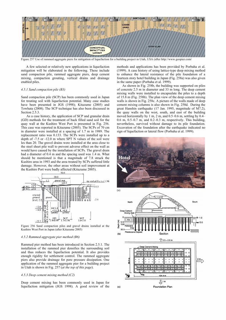
Figure 257 Use of rammed aggregate piers for mitigation of liquefaction for a building project in Utah, USA (after http://www.geopier.com/
A few selected or relatively new applications in liquefaction
mitigation will be elaborated in the following. These include sand compaction pile, rammed aggregate piers, deep cement mixing, compaction grouting, vertical drains and drainage enabled piles.
4.5.1 Sand compaction pile (B3)
Sand compaction pile (SCP) has been commonly used in Japan for treating soil with liquefaction potential. Many case studies have been presented in JGS (1998); Kitazume (2005) and Towhata (2008). The SCP technique has also been discussed in Section 2.5.3.
As a case history, the application of SCP and granular drain (GD) methods for the treatment of back filled sand soil for the quay wall at the Kushiro West Port is presented in Fig. 256. This case was reported in Kitazume (2005). The SCPs of 70 cm in diameter were installed at a spacing of 1.7 m in 1989. The replacement ratio was 0.133. The SCPs were installed up to a depth of -7.5 or -12.0 m where SPT N values of the soil were les than 20. The gravel drains were installed at the area close to the steel sheet pile wall to prevent adverse effect on the wall as would have caused by the installation of SCPs. The gravel drain had a diameter of 0.4 m and the spacing used was 1.4 m. What should be mentioned is that a magnitude of 7.8 struck the Kushiro area in 1993 and the area treated by SCPs suffered little damage. However, the other areas without soil improvement at the Kushiro Port were badly affected (Kitazume 2005).
Figure 256 Sand compaction piles and gravel drains installed at the Kushiro West Port in Japan (after Kitazume 2005)
4.5.2 Rammed aggregate pier method (B6)
Rammed pier method has been introduced in Section 2.5.1. The installation of the rammed pier densifies the surrounding soil and thus reduces the liquefaction potential. It also provides enough rigidity for settlement control. The rammed aggregate piers also provide drainage for pore pressure dissipation. One application of the rammed aggregate pier for a building project in Utah is shown in Fig. 257 (at the top of this page).
4.5.3 Deep cement mixing method (C2)
Deep cement mixing has been commonly used in Japan for liquefaction mitigation (JGS 1998). A good review of the
methods and applications has been provided by Porbaha et al. (1999). A case history of using lattice-type deep mixing method to enhance the lateral resistance of the pile foundation of a fourteen story hotel building in Japan (Fig. 258a) was also given in the same paper (Porbaha et al. 1999).
As shown in Fig. 258b, the building was supported on piles of concrete 2.5 m in diameter and 33 m long. The deep cement mixing walls were installed to encapsulate the piles to a depth of 15.8 m (Fig. 258b). The plan view of the deep cement mixing walls is shown in Fig. 258c. A picture of the walls made of deep cement mixing columns is also shown in Fig. 258d. During the great Hanshin earthquake (17 Jan. 1995, magnitude of M7.2), the quay walls on the west, south, and east of the building moved horizontally by 1 m, 2 m, and 0.5–0.6 m, settling by 0.4–0.6 m, 0.5–0.7 m, and 0.2–0.3 m, respectively. This building, nevertheless, survived without damage to its pile foundation. Excavation of the foundation after the earthquake indicated no sign of liquefaction or lateral flow (Porbaha et al. 1999).
(a)
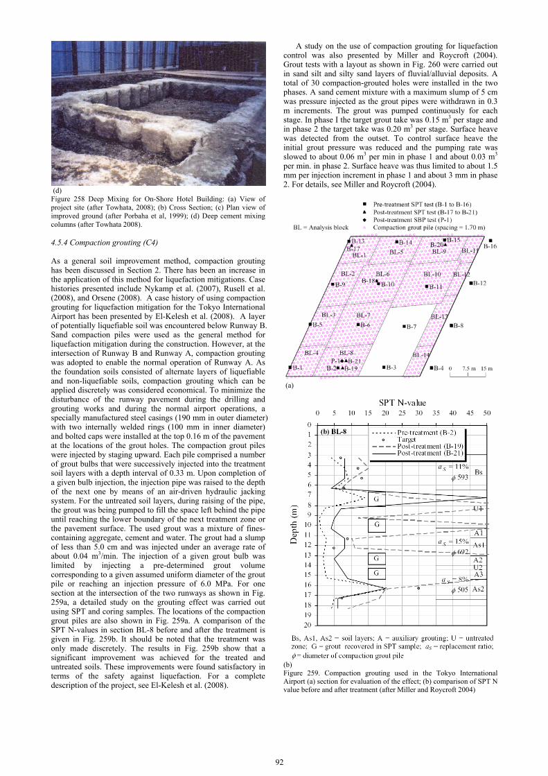
92
(d) Figure 258 Deep Mixing for On-Shore Hotel Building: (a) View of project site (after Towhata, 2008); (b) Cross Section; (c) Plan view of improved ground (after Porbaha et al, 1999); (d) Deep cement mixing columns (after Towhata 2008).
4.5.4 Compaction grouting (C4)
As a general soil improvement method, compaction grouting has been discussed in Section 2. There has been an increase in the application of this method for liquefaction mitigations. Case histories presented include Nykamp et al. (2007), Rusell et al. (2008), and Orsene (2008). A case history of using compaction grouting for liquefaction mitigation for the Tokyo International Airport has been presented by El-Kelesh et al. (2008). A layer of potentially liquefiable soil was encountered below Runway B. Sand compaction piles were used as the general method for liquefaction mitigation during the construction. However, at the intersection of Runway B and Runway A, compaction grouting was adopted to enable the normal operation of Runway A. As the foundation soils consisted of alternate layers of liquefiable and non-liquefiable soils, compaction grouting which can be applied discretely was considered economical. To minimize the disturbance of the runway pavement during the drilling and grouting works and during the normal airport operations, a specially manufactured steel casings (190 mm in outer diameter) with two internally welded rings (100 mm in inner diameter) and bolted caps were installed at the top 0.16 m of the pavement at the locations of the grout holes. The compaction grout piles were injected by staging upward. Each pile comprised a number of grout bulbs that were successively injected into the treatment soil layers with a depth interval of 0.33 m. Upon completion of a given bulb injection, the injection pipe was raised to the depth of the next one by means of an air-driven hydraulic jacking system. For the untreated soil layers, during raising of the pipe, the grout was being pumped to fill the space left behind the pipe until reaching the lower boundary of the next treatment zone or the pavement surface. The used grout was a mixture of fines-containing aggregate, cement and water. The grout had a slump of less than 5.0 cm and was injected under an average rate of about 0.04 m3/min. The injection of a given grout bulb was limited by injecting a pre-determined grout volume corresponding to a given assumed uniform diameter of the grout pile or reaching an injection pressure of 6.0 MPa. For one section at the intersection of the two runways as shown in Fig. 259a, a detailed study on the grouting effect was carried out using SPT and coring samples. The locations of the compaction grout piles are also shown in Fig. 259a. A comparison of the SPT N-values in section BL-8 before and after the treatment is given in Fig. 259b. It should be noted that the treatment was only made discretely. The results in Fig. 259b show that a significant improvement was achieved for the treated and untreated soils. These improvements were found satisfactory in terms of the safety against liquefaction. For a complete description of the project, see El-Kelesh et al. (2008).
A study on the use of compaction grouting for liquefaction control was also presented by Miller and Roycroft (2004). Grout tests with a layout as shown in Fig. 260 were carried out in sand silt and silty sand layers of fluvial/alluvial deposits. A total of 30 compaction-grouted holes were installed in the two phases. A sand cement mixture with a maximum slump of 5 cm was pressure injected as the grout pipes were withdrawn in 0.3 m increments. The grout was pumped continuously for each stage. In phase I the target grout take was 0.15 m3 per stage and in phase 2 the target take was 0.20 m3 per stage. Surface heave was detected from the outset. To control surface heave the initial grout pressure was reduced and the pumping rate was slowed to about 0.06 m3 per min in phase 1 and about 0.03 m3 per min. in phase 2. Surface heave was thus limited to about 1.5 mm per injection increment in phase 1 and about 3 mm in phase 2. For details, see Miller and Roycroft (2004).
(a)
(b) Figure 259. Compaction grouting used in the Tokyo International Airport (a) section for evaluation of the effect; (b) comparison of SPT N value before and after treatment (after Miller and Roycroft 2004)

Figure 260. Grouting test plan (after Miller and Roycroft 2004)
Based on the test results, the relationships between grout hole spacing, ground improvement, and threshold values of CPT tip resistance are shown in Fig. 261. Improvement in the CPT tip resistance was seen for both sandy silt and silty sand and for all the hole spacings and the improvement increases with decreasing spacing as expected. Miller and Roycroft (2004) suggested a grout spacing of 1.5 m for this project.
Figure 261 Grout hole spacing versus cone penetration test (CPT) (after Miller and Roycroft 2004)
4.5.5 Vertical drain method (D1)
The design and applications of gravel drains and artificial drains for liquefaction mitigation have been presented in detail in JGS (1998). One recent development is the use of a so-called EQ drain as presented by Rollins and Anderson (2003). The EQ drain is a prefabricated geo-composite as shown in Fig. 262. The core is made of plastic with open slots. The diameter of the
drain varies from 75 to 200 mm. The drain is wrapped with a fabric sleeve. The drain is installed using a hollow cylindrical mandrel with an anchor plate at the end, as shown in Fig. 263a. A mandrel with fins as shown in Fig. 263b is also used to combine the installation with densification of the sand layer. So far, there are no case histories available to verify the performance of the EQ drain. One field test using controlled blasting presented by Rollins and Anderson (2003) have shown that the EQ drain is effective in dissipating the excess pore water pressure generated during ground shaking and it can also reduce ground settlement by up to 50%. Similar observation has also been made in another study by Chang et al. (2004).
Figure 262 A picture of the EQ drain (after Rollins and Anderson 2003)

94
(a)
(b) Figure 263 Installation of EQ drain in sand for liquefaction mitigation using: (a) a cylindrical mandrel; (b) a mandrel with wings for vibro-compaction during installation (after Rollins and Anderson 2003)
4.5.6 Use of drainage enabled piles (D4)
Pile is a major foundation type in supporting upper structures. However, most of steel or concrete piles are impervious. Methods have been developed to use drainage enabled piles so piles can also be used to dissipate excess pore water pressure to reduce the liquefaction potential of sand. One example for sheet piles used in Japan is shown in Fig. 264 (Towhata 2008). Drain panels are attached to sheet piles. Another type is drain embedded precast concrete piles as shown in Fig. 265 (Liu 2007c). Model tests using a vibration table have shown that the drain embedded pile is effective in dissipating liquefaction (Liu 2007c).
Figure 264 Steel sheet piles with attached drainage pipes (after Towhata 2008)
4.5.7 Other emerging methods
As a result of the intensive research on liquefaction in the past years, several promising methods or techniques for liquefaction mitigation have been proposed or being studied. The first is electro-osmosis. Mitchell (2008a) proposed to use electro-osmosis together with permeation grouting in soil with a hydraulic conductivity less than about 1x10⁻⁵ to 1x10⁻⁶ m/s. A similar concept has been used for soil improvement for fine-grained soil as mentioned in Section 2.4.6.
Figure 265 Precast concrete piles with embedded drains: 1. concrete pile; 2 & 4. metal coil pipe and slot; 3 & 5. plastic drain and slot, after Liu (2007c). The second is the biocementation method. The use of microbiological method for soil improvement has been discussed in Section 2.5.7. One of the main advantages of the biocementation method is that the microorganisms can be easily introduced to sand layer without mixing or injection. The third method is to introduce tinny gas bubbles in saturated sand. Several studies (e.g., Yegian et al. 2007) have shown that when saturated sand is made slight unsaturated (say with a degree of saturation of 95%) by introducing gas bubbles, the amount of reduction in the excess pore water pressure of soil generated under a dynamic load will be great reduced. One way to introduce tinny gas bubbles is the use of microorganisms. This method is promising as it might be the method that consumes the least energy. However many more studies are required before this method can be used in practice. 4.6 Concluding remarks There are many other types of natural disasters (e.g., Kokusho 2005) that have not been discussed in this report. However, the basic mitigation principles and techniques presented in this report are applicable. The same may be applied to non-natural disasters such as construction failures (Moh and Hwang 2007) and some geoenvironmental problems.
Within the theme of this report, only technical issues related to geotechnical construction are reviewed. The suitability of a certain technique is heavily influenced by the social and economic background of the place where disaster mitigations need to be carried out as well as the availability of the materials, the construction machines and the level of support of infrastructure. It needs also to be pointed out that natural hazard mitigation is a multi-disciplinary subject. An effective hazard mitigation program requires much more than the technical matters. In conclusion, it may be apt to outline the framework proposed by Gilbert (2007) in guiding engineers in fulfilling their roles and responsibilities: 1) Decision making is the key to hazard mitigation. 2) Risk analyses should be designed specifically to produce
information relevant to decision making. 3) Mitigating consequences can be the most effective means to
mitigate natural hazard. 4) Performance depends on systems; the enormous scale and
complexity of systems for hazard mitigation, both in space and in time, makes it difficult to achieve a high level of reliability.
5) Dealing with uncertainty is a real challenge; physical factors and the role of uncertainty in decision making are important considerations in how best to account for and represent uncertainty in hazard mitigation.
6) Effective communication is essential in mitigating natural hazards; it is important that we reach out to and work with specialists who are experts in communication.
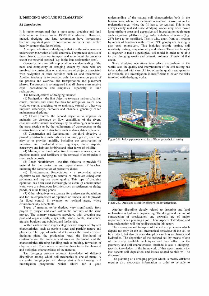
5. DREDGING AND LAND RECLAMATION
5.1 Introduction
It is rather exceptional that a topic about dredging and land reclamation is treated in an ISSMGE conference. However, indeed, dredging and land reclamation have increasingly become important parts of construction activities that involve heavily geotechnical knowledge.
A simple definition of dredging is that it is the subaqueous or underwater excavation of soils and rock. The process consists of three phases: excavation, transport and subsequent placement or use of the material dredged (e.g. in the land reclamation area).
Generally there are little appreciation or understanding of the need and complexity of dredging except by those who are involved in construction or maintenance of projects associated with navigation or other activities such as land reclamation. Another tendency is to consider only the excavation phase of the process and overlook the transportation and placement phases. The process is so integrated that all phases must receive equal consideration and emphasis, especially in land reclamation.
The basic objectives of dredging include: (1) Navigation – the first objective to create harbours, basins,
canals, marinas and other facilities for navigation called new work or capital dredging; or to maintain, extend or otherwise improve waterways, harbours and channels, generally called maintenance dredging.
(2) Flood Control- the second objective to improve or maintain the discharge or flow capabilities of the rivers, channels and/or natural waterways by maintaining or increasing the cross-section or by the realignment of watercourses or the construction of control structures such as dams, dikes or levees.
(3) Construction and Reclamation - the third objective to provide construction materials such as sand, gravel, shell and clay or to provide landfills, including the construction of industrial and residential areas, highways, dams, airports, causeways and habitats for birds and other forms of wildlife.
(4) Mining - the fourth objective to recover minerals, gems, precious metals, and fertilisers or the removal of overburden to reach such deposits.
(5) Beach Nourishment - the fifth objective to provide fill material for the protection and replenishment of beaches, including the construction of protective dunes.
(6) Environmental Remediation - a somewhat newer objective to use dredging to remove or remediate subaqueous pollutants and improve water quality. This type of dredging operation has been used increasingly to clean-up contaminated waterways or subaqueous facilities, such as settlement or sludge ponds, or mine tailing ponds.
(7) Other objectives to excavate for underwater foundations and for the emplacement of pipelines or tunnels, and to provide for flood control in swampy or lowland areas, where environmentally acceptable.
Types of material to be dredged vary significantly from project to project and even within the confines of the same project. The primary categories associated with dredging are: peat and organic soils, clays, silts, sands, corals, sandstones, gravels, boulders and cobbles, and (soft) rock.
Within each of these major categories are ranges of physical characteristics, such as particle sizes and particle nature and plasticity. The type of material determines the most effective dredging plant, the production rates, the likelihood of contamination, the potential end uses or placement, and the characteristics affecting handling such as bulking, formation of clay balls, etc. There is also a need to characterise the chemical and biological characteristics of the material.
The dredging process requires knowledge of different disciplines among which soil mechanics is one of many. A successful dredging job will always start with a thorough soil investigation programme which allows for a good
understanding of the natural soil characteristics both in the borrow area, where the reclamation material is won, as in the reclamation area, where the fill has to be realised. This is not always easily realised since dredging works very often cover large offshore areas and expensive soil investigation equipment such as jack-up platforms (Fig. 266) or dedicated vessels (Fig. 267) have to be mobilised. This is why, apart from soil testing by means of boreholes with SPT or CPT, geophysical testing is also used extensively. This includes seismic testing, soil resistivity testing, magnetometry and others. These are brought all together to make a geological soil model in order to be able to plan dredging works and estimate volumes of material that occur.
Since dredging operations take place everywhere in the world, also the quality and interpretation of the soil testing has to be addressed with care. All too often the quality and quantity of available soil investigation is insufficient to cover the risks involved with dredging works.
Figure 266. Jack-up pontoon used for offshore geotechnical testing.
Figure 267. Dedicated vessel for offshore soil investigations.
Another discipline closely related to dredging and land
reclamation is hydraulic engineering. The design and method of construction of breakwaters and seawalls are of major importance when planning a job. These aspects of dredging and land reclamation will not be discussed in this report.
The excavation and transport of the soil are processes which depend not only on the soil mechanical behaviour of the soil to be dredged, but also on other disciplines such as mechanics and hydraulics. The deposition of the dredged soil by means of one of the many available techniques and their effect on the geometry and soil characteristics obtained is also a dredging-specific knowledge. In the framework of this report, mainly the last aspect: soil deposition and issues related to this will be discussed.
The planning of a dredging project which is mostly offshore requires also met-ocean information in order to be able to

96
predict the workability of the different dredging vessels. This issue will not be discussed here.
General information on dredging and dredging related organisations and companies can be found from the International Association of Dredging Companies (IADC; www.iadc-dredging.com). Basic literature about dredging can be found from Bray et al (1997) and Bray (2004; 2008).
5.2 Dredging methods
There are a variety of dredgers and means to employ them. Their usage will be project specific. No single type of dredger or system can suit all projects. The quantity and type of material to be dredged, placement or relocation alternatives, availability of equipment or cost of mobilisation are some of the factors affecting the ultimate decision.
There are a number of schemes for describing types of dredgers. In this report, the types of dredgers are described by
the three broad classifications on the basis of the mode of excavation and operation (see also Table 23):
(1) mechanical dredgers, (2) hydraulic dredgers, (3) mechanical/hydraulic dredgers which utilise both basic
elements in some combination, (4) hydrodynamic dredgers. Within these four categories further subdivision can be made
on the basis of propulsion, that is, those which are self-propelled either during the excavation phase, the transportation phase or both, and those which are non-self-propelled.
The production rate for the dredger varies widely depending on the circumstances, the material to be dredged and the transport and disposal methods employed. Other factors such as weather and sea state, ship traffic, depth, depth of the dredging face also affect dredging production rates. Production rates can range from 50 cubic metres to 4000 cubic metres per hour.
Table 23 Classification of common dredging methods and their main characteristics.
Category Method Main characteristics
Mechanical
Grab/Clamshell/Dragline Soil excavated with grabs (up to 200m³). Hydraulic clamshell shows better performance. Dredging of all soil materials up to firm clays. Exceptional in harder soils (special grabs). Fills barges for excavated soil transport. Stationary; from on a pontoon with spuds or anchored. Dredging at large depths (up to 100m).
Backhoe
Soil excavated with excavator bucket (up to 30m³). Dredging of all soil material up to soft rock (UCS < 5 MPa). Can handle large boulders. High selectivity and accuracy. Fills barges for excavated soil transport. Stationary; from on a pontoon with spuds. Dredging depth practically limited to 30m.
Dipper
Soil and Soft Rock excavated with a shovel (up to 15m³). Fills barges for soil transport. Stationary; from on a pontoon with spuds.
Bucket-Ladder
Soil excavated with chain of buckets guided by a ladder. Dredging of all soil material, including soft rock. Good selectivity and accuracy. Fill barges for excavated soil transport Stationary pontoon with anchors Dredge depth up to 30m
Hydraulic
Plain Suction
Excavation of non cohesive soils by means of suction with help of jets. Material is pumped ashore or into barges. Stationary pontoon with anchors. Dredge depth up to 50m.
Dustpan
Excavation of thin layers of soft/cohesionless material in rivers Material is sidecasted. Limited dredging depths.
Mechanical/
hydraulic
Cutter Suction Dredger (CSD)
Excavation of the soil/rock material by means of a cutter wheel. Hydraulic suction of the material. Moderate to good selectivity and accuracy. Transport hydraulically by (floating) pipe lines to land reclamation site or filling of barges. Stationary pontoon with spuds and anchors sensitive for waves and currents. Dredged depths up to 30m.
Trailing Hopper Suction Dredger (TSHD)
Excavation of the uncemented soil by means of a suction head (with water jets and teeth). Moderate selectivity and accuracy. Hydraulic suction of the material and deposition in the hopper bin. Sailing vessel, suitable for long distances. Limited by draught. Dumps of pumps the dredged material (in)to the land reclamation area Hopper volumes from a few thousand m³ up to 46 000m³. Dredging depth commonly 50m to 60m; larger vessels even over 100m.
Hydrodynamic
Water Injection
Excavation of soft fine materials by means of water jetting Material in suspension is transported by the bed slope, natural water current or density gradient
Plough, Beams and Rakes
These devices put the material to be removed either directly or indirectly into the water column as suspended sediment. Material in suspension is transported by the bed slope, natural water current or density gradient
No productions are given in this overview. These depend on many parameters such as dredging equipment type and its installed power, the dredging depth, the transport distance, the soil material and its strength characteristics

5.2.1 Mechanical dredgers
This category employs mechanical means for the excavation of material and is often similar to equipment used for dry land excavation.
(1) Grab or clamshell (Figs. 268 and 269) and dragline These employ either rotating cabs or fixed A-frame type
barge-mounted equipment. They have hoisting and control systems and use clamshell digging devices or buckets rigged on cables to excavate the material from the bottom and transport it vertically out of the water and into barges for subsequent transport to the placement area. Clamshell dredgers can be used in sands, some types of clay, gravel, cobbles and some broken rock dredging situations. They are not particularly effective in fine silts which have a tendency to run out of the bucket. They are nonetheless used for this purpose in smaller jobs or when fitted with special sealed buckets.
One advantage of clamshell dredgers is their ability to dredge in fairly deep waters and their ability to do precise spot dredging either to remove isolated areas above grade in the navigation prism or along docks and corners of docks. Depending on the type of material dredged, they have moderate to low production rates. They are normally non-self-propelled and are fixed at the excavation site using anchors or spuds.
Figure 268. Main features of a Grab Dredger (after Bray et al 1997).
Figure 269. Grab dredger
(2) Backhoe (Figs.270 and 271) The backhoe is common to dry land excavators and is
increasingly being employed for dredging. As in the case above, they are barge-mounted for dredging, generally non-self-propelled and can have moderate production rates. They employ an articulated excavation bucket mounted on an articulated boom. They generally use hydraulically operated rams for movement, positioning and excavating. The material is excavated, brought to the surface and placed in barges for transport to the placement area. They can dig a broad range of materials such as; sand, clays, gravel, cobbles and fractured and unfractured moderately hard rock. They do have radius and depth limitations but with some newer models increased
excavating depths are possible. These dredgers are likewise generally non-self-propelled and require anchors or spuds to fix them at the dredging location.
Figure 270. Main features of a backhoe dredger (after Bray et al 1997)
Figure 271. Backhoe dredger
(3) Dipper (Fig. 272) The dipper dredger is essentially a powered shovel mounted
on a barge. Older versions used a rotating boom with a stick and shovel design. Later designs incorporate the "whirley" or rotating cab, luffing boom and a stick and bucket. These dredgers use vertical spuds to anchor them to the bottom and a digging spud at the rear of the vessel to provide resistance to the massive digging forces of the bucket. Dipper dredges come in all sizes but the largest of the new dipper dredgers have bucket capacities greater than 15 cubic metres. The dredger operates by using teeth on the lip of the bucket to excavate the material from the bottom or digging face. Once the bucket is full the dipper stick is withdrawn upwards and the cab and boom rotated so the bucket is over the barge or scow, the bottom of the bucket is released thereby dumping the contents of the bucket into the barge. The dredged material is then transported to the placement area by barges or scows. The barges or scows may be either self-propelled or propelled by attendant motor vessels such as tugs.
Dipper dredgers are particularly suited for dredging hard rock and highly compacted materials. They have also been used effectively in removing old subaqueous foundations from within the project. There are limitations on dredging depths which can be dredged by dipper dredgers. Much of the work previously done by dipper dredgers is now done by backhoes, although large dippers are still in use and compete quite effectively with other types of dredgers in terms of production and cost.

98
Figure 272. Main features of a dipper dredger (after Bray et al 1997).
(4) Bucket-ladder (Figs. 273 and 274) Bucket-ladder dredgers once comprised a major part of the
European dredging fleet and are in fact the direct descendants of the historic mud mills, the first "dredgers". They use a series of buckets mounted to an endless chain loop. The loop is powered causing the buckets to travel in such a manner as to scoop the material from the bottom, carry the material in the upright buckets up the ladder to the top of the ladder where the buckets then rotate into an upside down position thereby dumping their contents into a chute. The material is then sent through the chutes to barges or scows alongside the dredger.
Like the other mechanical dredgers, barges or scows are used to transport the dredged material to the placement or relocation sites. They can be effectively used in a wide variety of materials up to and including soft rock material. These dredgers were sometimes self-propelled to provide transport to the dredging site. They fell into disuse because of their relatively low production rates, the need for anchor lines which often interfered with navigation traffic, and their relatively high noise levels.
Figure 273. Main features of a bucket ladder dredger (after Bray et al 1997).
Figure 274. Bucket Ladder Dredger.
5.2.2 Hydraulic dredgers
These dredgers use hydraulic centrifugal pumps to provide the excavating force, without mechanical cutters, and hydraulic transport force to carry slurried solids from the digging site through a pipeline to the surface and thence through a discharge pipeline to the disposal site. In some special cases, hydraulic dredgers do pump into barges for subsequent transport to the placement site.
(1) Plain suction (Fig. 275) They can dig at great depths using ladder mounted
centrifugal pumps to enhance production at deeper depths. They are effective in non-cohesive materials such as sands and gravels and are used extensively in aggregate winning operations and large reclamation projects. Because of their inability to handle cohesive materials and their characteristic to produce small deep excavations, they are rarely suitable or used for channel or harbour construction projects.
They can be either stationary or self-propelled, although self-propulsion is not used during the excavation process. In suitable materials, they have high production rates.
Figure 275. Main features of a plain suction dredger (after Bray et al 1997).
(2) Dustpan A rather special type of suction dredger, called the dustpan
dredge is used on river systems. They are effective where there are high bed loads or suspended solid concentrations of sand and small gravel and which, when conditions are right, form bars or obstructions in the navigation channels.
The dustpan dredgers are capable of moving large volumes of material from localised areas using a suction head shaped much like a dustpan. The material is usually slurried by use of water jets along the top of the digging face of the dustpan, drawn into the suction head and up the suction pipeline, through the pump and thence through a relatively short floating discharge line. The material is discharged into a portion of the river where high energy currents keep it in suspension and it is carried downstream and away from the constricting bar. Dustpan dredgers are not generally used for construction dredging and were originally designed for use in large river navigation systems where conditions are appropriate for their design and use.
5.2.3 Mechanical/hydraulic dredgers
Mechanical/hydraulic dredgers include the real workhorses of the dredging industry. The cutter suction dredger (CSD) or cutter-head dredger, bucket-wheel dredger and trailing suction hopper dredger (TSHD) are representative of mechanical/hydraulic dredgers. These dredgers are employed on construction and maintenance projects depending on the nature and quantities of material to be excavated.
(1) Cutter-head and bucket-wheel dredgers (Figs. 276 and 277) Both the cutter-head and bucket-wheel dredgers use rotating
mechanical devices, called cutters, mounted ahead of the suction head. The cutters excavate the material into suitably

sized material. This is then sucked into the suction pipe as a slurry and pumped to the surface. By use of pumps mounted on the ladder or a structural device which extends to the bottom, these dredgers can dig effectively at depths approaching 25-30 metres or more in special cases.
They are characterised by high production rates and the ability to effectively dig silts, clays, sand, gravel, cobbles, fractured and sound rocks. They work in a stationary mode either on spuds or anchors. Some are self-propelled to provide for transportation between work-sites. They have flexible discharge alternatives and can either discharge into barges or, as is generally the case, through discharge pipelines to the placement site. By use of booster pumps in the discharge lines, they can transport and place materials at considerable distances from the work site.
Cutter-heads rotate along the axis of the suction pipe whereas bucket-wheel dredgers rotate perpendicular to the axis of the suction pipe. The bucket-wheel is more commonly used in mining applications.
Figure 276. Main features of a Cutter Suction Dredger (after Bray et al 1997).
Figure 277. Self-propelled Cutter Suction Dredger.
(2) Trailing suction hopper dredgers (TSHD) (Figs.278 and 279) Trailing hopper dredges are self-propelled ships with
hoppers or dredged material storage internal to the hull. They have articulated dredging or dragarms which extend to the sea bottom. They dredge whilst underway travelling at low speeds.
The draghead can be either passive or active. In the case of the passive draghead, no additional power is applied at the draghead and it depends on the scouring of the material to be excavated by hydraulic currents induced at the draghead. The active draghead employs power to drive either cutters or water jets to excavate the material and aid in slurrying the material.
The weight of the drag system maintains the contact with the bottom material in either passive or active dragheads and allows the material to be transported hydraulically as slurry. In both cases, the material is hydraulically transported through suction lines, through the centrifugal pump and into the hoppers where
the solids settle out and the material is retained for transport and subsequent placement.
Trailing suction hopper dredgers are quite flexible in terms of the material to be dredged, placement alternatives, and the ability to work in protected and unprotected waters.
The material is transported internally in hoppers within the vessel to a placement site remote from the work site. The material is discharged through doors or valves in the hopper bottom, or in the case of a split-hulled vessel, out the bottom when the hull is longitudinally split; or it can be pumped from the hoppers through discharge lines to shore based placement sites with or without the use of booster pumps. Trailing suction hopper dredgers can dig effectively at depths of up to 100 metres using pumps mounted on the dragarm close to the draghead. They are effective in silts, sands, clays and gravels but are not generally used in rock dredging. They have relatively high production rates. They have the additional advantage that since they are self-propelled, they can work in congested areas with minimum disruption to ship traffic. They can also work in unprotected waters such as entrance channels far out to sea and under weather and sea conditions where stationary equipment is somewhat limited. The trailing suction hopper dredger is unique in the sense that it uses its self-propulsion during the excavation and transportation processes.
Figure 278. Main features of a Trailing Suction Hopper Dredger (after Bray et al 1997).
Figure 279. Trailing suction Hopper Dredger.
5.2.4 Hydrodynamic dredgers
Hydrodynamic dredgers mobilise material underwater and use the bed slopes, natural water currents and density gradients at the dredging site to move the material to a different location. They may be mechanical or hydraulic. Dome of the dredgers described above can be used in hydrodynamic mode. Those described below are specifically designed for the purpose.

100
(1) Water injection Although this type process has been known for some time
and utilised in special circumstances, the water injection dredger is finding some notable successes at the current time, primarily for maintenance dredging. The dredger uses water pressure to fluidise the bottom material to be removed creating a dense fluid slurry. The slurry is then transported from the excavation site by means of currents induced either by the density gradient between the slurry and that of water, or by naturally occurring currents within the dredging site, such as tidal or river currents.
This is a relatively low-cost dredging technique which is limited to silts and unconsolidated clays and fine sands. The system can either be barge-mounted, self-propelled or stationary or be a fixed structure associated with a quay where siltation is known to occur. The material removed does not flow through the centrifugal pumps as in the case of the other hydraulic dredgers but uses the centrifugal-pump-induced water jets to fluids the bottom material that then flows from the dredging site as a result of density differentials in the water column.
(2) Ploughs, beams and rakes This is a category of devices that is generally suspended from an A-frame, mounted on the aft end of a tug boat, and dragged across the sea- or riverbed. Ploughs may be specially designed beams or bottomless buckets that contain the bed material for a short period of time, whilst rakes and beams are generally of a form which merely re-suspends the bed material. All these devices put the material to be removed either directly or indirectly into the water column as suspended sediment.
Ploughs, beams and rakes have relatively very low production rates, but are inexpensive to mobilise and use. They may often be suspended from marine plant owned by the client. They may be used in conjunction with a trailer dredger.
5.2.5 Choice of type of dredger
The choice of dredger used on a specific project depends on a number of factors. Type of material to be dredged is a primary factor. Hard rock dredging generally limits the types of dredgers to mechanical dredgers or cutter-head dredgers designed specifically for rock dredging.
Where the material can be suitably dredged by several types of dredgers, then a more detailed consideration of operating parameters is required. Trailing hopper dredgers are able to work effectively in entrance channels where sea and traffic conditions make stationary plant less desirable and effective. The location of the dredged material placement areas and access to them may also play an important role in the decision on the most suitable and effective dredger type.
As stated above, cutter-head dredgers can pump long distances to remote disposal areas and do so, more or less, on a continuous basis. Hopper dredges under the same circumstances may spend a considerable time transporting material for placement, particularly where shallow water depths restrict navigation. This further increases haul distances.
Likewise, mechanical dredgers using barge or scows for transport may require large numbers of barges and support equipment such as tugs and tenders. These factors require both technical and economic analysis in the decision process. For instance, the most effective dredger may not be available close to the work site and then mobilisation time and cost must be factored into the decision.
5.2.6 Transport of dredged material
The transport of dredged material is an integral part of the dredging process and is determined to a large extent on the type of equipment employed and the placement options available. As discussed above, hydraulic suction and cutter-head dredgers use pipelines to transport dredged materials to the placement site.
For long distances to the placement areas one or more booster pumps may be required at intervals along the discharge line. Discharge lines may be floating or pontoon mounted, or can be submerged where floating lines would interfere with navigation or shore pipelines. Often, all three discharge pipelines may be used on the same project.
Mechanical dredgers must use barges or scows for transportation. In these cases, unless the barges are self-propelled, ancillary power vessels such as tugs or tenders are used to tow or push the transport barges. These barges may be transported individually or in groups depending upon the power of the power vessels and sea conditions. The barges or scows used for placement usually contain pockets in which the dredged material is placed. The material is unloaded from the barges by being dumped through the bottom either through cable or hydraulically operated doors, or in the case of split-hulled barges by splitting the barge longitudinally. There are cases where the barges are unloaded using hydraulic pumps or mechanical equipment. In the case of dustpan dredgers and water injection dredgers, the transport of dredged material depends on the energy contained in the water currents.
5.2.7 Placement of dredged material
The ultimate step in the dredging process is to place, relocate, dispose or deposit the material in a location away from that where it was excavated. There are a number of placement alternatives. The basic options are:
(1) open water, (2) intertidal and upland, or (3) shore placement sites. The option or options employed depend on a number of
factors, such as: accessibility to the work site, type of dredger and transport system, whether the dredged material contains contaminants, costs, and environmental factors.
It is always desirable to use the dredged material for beneficial purposes. Such purposes may be to create fast land for subsequent construction purposes, use as aggregates, creation of wildlife habitat, construction of shore protection features, beach nourishment or to fill abandoned mine or quarry excavations or even, when the material is suitable, for topsoil. When used for beneficial purposes there is generally a cost benefit to be achieved thereby reducing the actual cost of dredging for navigation purposes.
If beneficial uses are not possible, either because of the nature, volume or contamination of the dredged material, then placement should be conducted in a manner which creates minimum environmental damage, is cost effective, and for which sites can be reasonably acquired.
5.2.8 New developments in dredging methods
Dredging is a continuously evolving business where many engineering disciplines are joined in order to come to best performance. New developments can be seen in different fields among which the following are most important:
(1) Increase in size and power of dredging equipment In the past 2 decades, the size of trailing suction hopper
dredgers has tripled and plans for size in the range of 50 000m³ capacity exist (Fig. 280). This development is mainly influenced by the fact that in some areas no suitable construction materials can be found at limited distance (e.g. Singapore with its large land reclamation projects). In order to optimise the process of sand winning at large distances, larger hoppers have been designed.

Figure 280. Jan De Nul dredger Christobal Colon when launched from the construction platform (46 000 m³ hopper capacity).
Also in the field of cutter suction dredger’s, larger, more
powerful and more flexible equipment has been build. A clear example of this are the self-propelled cutter suction dredger’s with up to 6000 kW power on the cutter head. Such developments are mainly driven by the need for dredging and reclaiming in areas where (soft) rock is found. There also is an ongoing search for dredging harder rock since this is more economical and at higher production rates compared to drilling and blasting. The higher power is one of the components while the design of the cutter head and teeth and the maintenance/replacement of the teeth certainly are items for research.
In the field of backhoe dredgers also larger equipment is being produced with the new BackActer equipment. This is a new concept for backhoe dredgers. Where the a backhoe in the past always was based on land excavator equipment, the BackActer uses a new concept with a main features a larger slewing ring that connects the equipment to the platform and all vulnerable technical components have been taken out the upper carriage and have been mounted under deck (Fig. 281).
Figure 281. BackActer backhoe.
(2) Specialised dredging equipment Dredgers are adapted to dredge at greater depths by means of
longer suction pipes and underwater pumps. Dredging depths over 100m can be reached at present.
Grab dredgers with ROV have been developed for precision dredging at even larger depths (Fig. 282).
Figure 282. Special grab dredge with ROV for operation at large depths.
Purposely built equipment such as gravel dredgers with high loading capacity versus hopper content and on board sieving and washing/dewatering equipment have been developed. Gravel dredgers such as the Charlemangne (Fig. 283) are also equipped for dry unloading of the dredged material.
Figure 283. Gravel Dredger Charlemagne (5000 m³ hopper capacity)
(3) Environmental developments In the framework of environmental dredging works many
different adaptations to classical dredging have been developed in order to be able to dredge very precisely contaminated sediments at the bottom of harbours or rivers without causing spill and turbidity. Both in the field of mechanical dredging (drag and grab dredgers and in the field of hydraulic dredging (scoop and sweep dredgers) special equipment has been developed (Vandycke et al, 1996; Van der Sluijs et al, 1996). The ECODRAG is an adapted bucket ladder dredger. The ECOGRAB is a special grab (2 m³) that opens en closes following a horizontal plane and in closed position all openings are sealed (Fig. 284). The SCOOP an SWEEP dredgers are upgraded cutter suction dredgers with adapted suction heads equipped with additional screens. The SWEEP dredge is specially designed for dredging of thin layers. In the field of trailing suction hopper dredgers environmental developments have been made in the field of precision of the drag head position and depth, the overflow and water jetting systems in order to allow the dredging of high density mixtures.

102
Figure 284. ECOGRAB environmental dredging grab.
After dredging contaminated soil, it has to be deposited. This
can be in an on land disposal. The hydraulically dredged material is mixed with transportation water, what causes a volume increase of the material and extra water which is contaminated and needs to be treated in a water treatment plant. In order to avoid this, techniques for high density dredging (minimum use of water) have been developed.
The auger dredger has been developed for precise dredging of thin layers at the in situ density. The auger transports the material at its in situ density to the underwater pump and high density dredging is realised (Fig. 285).
Figure 285. Auger dredger.
(4) Supporting techniques leading to new possibilities A combination of dredging and up-to-date survey techniques
allow for very precise positioning and execution of underwater works such as the preparation of foundations for caisson structures, the realisation and backfilling of trenches for pipe lines and so on. In Fig. 286, a multi-beam image of a dredged and backfilled foundation pit for a caisson structure, to be used as foundation for an offshore wind turbine, is given (Mengé et al 2008). This image shows the high degree of precision that can be reached in dredging and backfilling operations at remote offshore areas and the possibility to visualise this with up-to-date survey techniques.
Up-to-date dredgers are large investments and are equipped with all latest techniques and electronics. One-man bridge is a new concept where dredging and sailing is steered by 1 operator managing all parameters relevant for the dredging process. Training to use state of the art dredging equipment, whether this is TSHD, cutter suction dredger or Backhoe dredgers, is performed on simulators designed especially for each type of equipment.
During dredging the known information about the soil to be dredged and new information acquired from monitoring during dredging (survey, production, type of soil, densities, geophysical data, tec.) are gathered in one GIS-system in real
time, which allows the operator to view and adapt his operations in order to obtain an optimised result. Such Soil View systems have been developed in function of the project requirement by different dredging companies.
Figure 286. Dredged foundation pit with gravel bed for a caisson structure.
5.3 Land reclamation methods and processes
5.3.1 Influence of dredging method on the reclamation material
Dredging techniques are mainly subdivided in ‘mechanical’ dredging and ‘hydraulic’ dredging. In the first the excavated material is not mixed with water for transport but the transport is realised by means of barges. The hydraulic techniques however are used most and include the cutter suction dredger and trailing suction hopper dredger. With these techniques, the excavation, the transport of the excavated material to the hopper or immediately to the reclamation area is realised by means of hydraulic transport. While in the mechanical dredging techniques the characteristics of the dredged material change only to a limited extend, the change of soil characteristics with the hydraulic techniques can be very important.
The change in characteristics depends largely on the type of material dredged as well. With cohesionless soil, hydraulically dredged, the soil structure is completely destroyed and the material is pumped into the hopper or directly to the reclamation area. The main sources of material loss that occur are: 1) In the hopper the finer material which does not readily settle
disappears through the overflow of the hopper in order to come to an optimal loading of the hopper. When overflow is not allowed because of turbidity restrictions, the filling of the hopper will not be optimal and less efficiency is achieved;
2) In the reclamation area, where the material is placed with a large amount of excess water (Fig. 287) segregation of the finer particles from the coarser cannot be prevented. As a result of the above given reasons, the sand in the
reclamation area will be coarser than the sand in the borrow area while some material is lost or is caught in a siltation pond when turbidity specifications require so. The coarser material is not really a problem as long as the new particle size does not become to uniform which could cause problems for compaction. Normally the specifications for a granular reclamation material will include a requirement with regard to the % of fines (< 63 micron) of max 10% to 20%, so the loss of fines will help in achieving this requirement. The segregated fines however cause a lot of problems in the reclamation area: accumulation at locations with low flow velocity and close to the water boxes
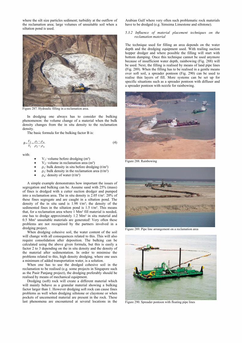
where the silt size particles sediment; turbidity at the outflow of the reclamation area; large volumes of unsuitable soil when a siltation pond is used.
Figure 287. Hydraulic filling in a reclamation area.
In dredging one always has to consider the bulking
phenomenon: the volume change of a material when the bulk density changes from the in situ density to the reclamation density.
The basic formula for the bulking factor B is:
w
wVVB
ρρρρ
−−
==2
1
1
2 (4)
with: • V1: volume before dredging (m³) • V2: volume in reclamation area (m³) • ρ1: bulk density in situ before dredging (t/m³) • ρ2: bulk density in the reclamation area (t/m³) • ρw: density of water (t/m³)
A simple example demonstrates how important the issues of
segregation and bulking can be. Assume sand with 25% (mass) of fines is dredged with a cutter suction dredger and pumped into a reclamation area. The in situ density is 2.05 t/m³. 20% of these fines segregate and are caught in a siltation pond. The density of the in situ sand is 1.98 t/m³; the density of the sedimented fines in the siltation pond is 1.5 t/m³. This means that, for a reclamation area where 1 Mm³ fill material is needed, one has to dredge approximately 1.2 Mm³ in situ material and 0.5 Mm³ unsuitable materials are generated! Very often these problems are not recognised by the partners involved in a dredging project.
When dredging cohesive soil, the water content of the soil will change with all consequences related to this. This will also require consolidation after deposition. The bulking can be calculated using the above given formula, but this is easily a factor 2 to 3 depending on the in situ density and the density of the material after sedimentation. In order to minimise the problems related to this, high density dredging, where one uses a minimum of added transportation water, is a solution.
When one has to use the dredged cohesive soil in the reclamation to be realised (e.g. some projects in Singapore such as the Pasir Panjang project), the dredging preferably should be realised by means of mechanical equipment.
Dredging (soft) rock will create a different material which will mainly behave as a granular material showing a bulking factor larger than 1. However dredging soft rock can cause fines problems as well when dredging siltstone or claystone or when pockets of uncemented material are present in the rock. These last phenomena are encountered at several locations in the
Arabian Gulf where very often such problematic rock materials have to be dredged (e.g. Simsima Limestone and siltstone).
5.3.2 Influence of material placement techniques on the reclamation material
The technique used for filling an area depends on the water depth and the dredging equipment used. With trailing suction hopper dredger and where possible the filling will start with bottom dumping. Once this technique cannot be used anymore because of insufficient water depth, rainbowing (Fig. 288) will be used. Next, the filling is realised by means of land pipe lines (Fig. 289). When the filling has to be realised in a gentle means over soft soil, a spreader pontoon (Fig. 290) can be used to realise thin layers of fill. More systems can be set up for specific situations such as a spreader pontoon with diffuser and a spreader pontoon with nozzle for rainbowing.
Figure 288. Rainbowing
Figure 289. Pipe line arrangement on a reclamation area
Figure 290. Spreader pontoon with floating pipe lines
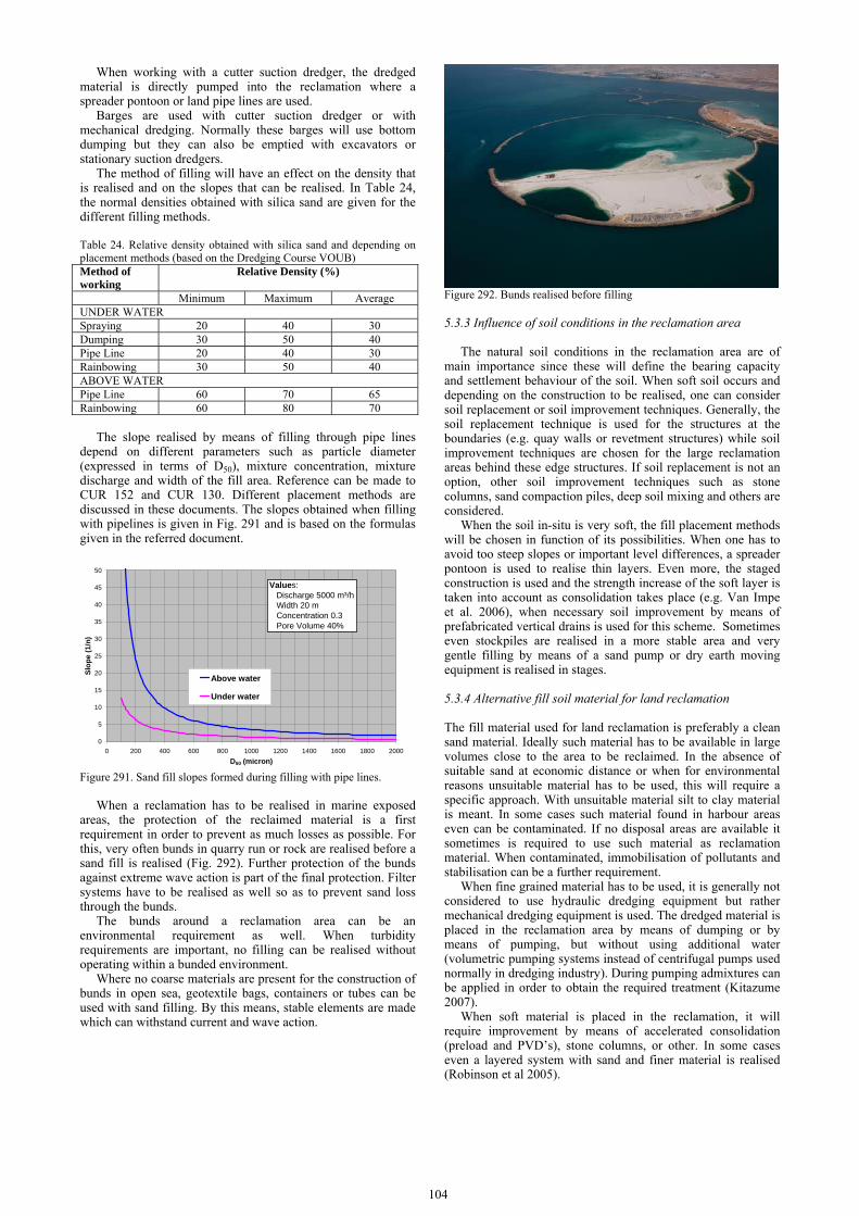
104
When working with a cutter suction dredger, the dredged material is directly pumped into the reclamation where a spreader pontoon or land pipe lines are used.
Barges are used with cutter suction dredger or with mechanical dredging. Normally these barges will use bottom dumping but they can also be emptied with excavators or stationary suction dredgers.
The method of filling will have an effect on the density that is realised and on the slopes that can be realised. In Table 24, the normal densities obtained with silica sand are given for the different filling methods.
Table 24. Relative density obtained with silica sand and depending on placement methods (based on the Dredging Course VOUB) Method of working
Relative Density (%)
Minimum Maximum AverageUNDER WATER Spraying 20 40 30Dumping 30 50 40Pipe Line 20 40 30Rainbowing 30 50 40ABOVE WATER Pipe Line 60 70 65Rainbowing 60 80 70
The slope realised by means of filling through pipe lines
depend on different parameters such as particle diameter (expressed in terms of D50), mixture concentration, mixture discharge and width of the fill area. Reference can be made to CUR 152 and CUR 130. Different placement methods are discussed in these documents. The slopes obtained when filling with pipelines is given in Fig. 291 and is based on the formulas given in the referred document.
0
5
10
15
20
25
30
35
40
45
50
0 200 400 600 800 1000 1200 1400 1600 1800 2000D50 (micron)
Slop
e (1
/n)
Above water
Under water
Values: Discharge 5000 m³/h Width 20 m Concentration 0.3 Pore Volume 40%
Figure 291. Sand fill slopes formed during filling with pipe lines.
When a reclamation has to be realised in marine exposed
areas, the protection of the reclaimed material is a first requirement in order to prevent as much losses as possible. For this, very often bunds in quarry run or rock are realised before a sand fill is realised (Fig. 292). Further protection of the bunds against extreme wave action is part of the final protection. Filter systems have to be realised as well so as to prevent sand loss through the bunds.
The bunds around a reclamation area can be an environmental requirement as well. When turbidity requirements are important, no filling can be realised without operating within a bunded environment.
Where no coarse materials are present for the construction of bunds in open sea, geotextile bags, containers or tubes can be used with sand filling. By this means, stable elements are made which can withstand current and wave action.
Figure 292. Bunds realised before filling
5.3.3 Influence of soil conditions in the reclamation area
The natural soil conditions in the reclamation area are of main importance since these will define the bearing capacity and settlement behaviour of the soil. When soft soil occurs and depending on the construction to be realised, one can consider soil replacement or soil improvement techniques. Generally, the soil replacement technique is used for the structures at the boundaries (e.g. quay walls or revetment structures) while soil improvement techniques are chosen for the large reclamation areas behind these edge structures. If soil replacement is not an option, other soil improvement techniques such as stone columns, sand compaction piles, deep soil mixing and others are considered.
When the soil in-situ is very soft, the fill placement methods will be chosen in function of its possibilities. When one has to avoid too steep slopes or important level differences, a spreader pontoon is used to realise thin layers. Even more, the staged construction is used and the strength increase of the soft layer is taken into account as consolidation takes place (e.g. Van Impe et al. 2006), when necessary soil improvement by means of prefabricated vertical drains is used for this scheme. Sometimes even stockpiles are realised in a more stable area and very gentle filling by means of a sand pump or dry earth moving equipment is realised in stages.
5.3.4 Alternative fill soil material for land reclamation
The fill material used for land reclamation is preferably a clean sand material. Ideally such material has to be available in large volumes close to the area to be reclaimed. In the absence of suitable sand at economic distance or when for environmental reasons unsuitable material has to be used, this will require a specific approach. With unsuitable material silt to clay material is meant. In some cases such material found in harbour areas even can be contaminated. If no disposal areas are available it sometimes is required to use such material as reclamation material. When contaminated, immobilisation of pollutants and stabilisation can be a further requirement.
When fine grained material has to be used, it is generally not considered to use hydraulic dredging equipment but rather mechanical dredging equipment is used. The dredged material is placed in the reclamation area by means of dumping or by means of pumping, but without using additional water (volumetric pumping systems instead of centrifugal pumps used normally in dredging industry). During pumping admixtures can be applied in order to obtain the required treatment (Kitazume 2007).
When soft material is placed in the reclamation, it will require improvement by means of accelerated consolidation (preload and PVD’s), stone columns, or other. In some cases even a layered system with sand and finer material is realised (Robinson et al 2005).

When the soft material is stabilised (in line mixing of cement or other admixtures), the treated soil is pumped into the reclamation area without further treatment. The quality of the hardened treated soil is of main importance in such an application (The Premixing Method 2003).
5.3.5 Soil Improvement techniques used for the improvement of the natural soil
For the treatment of natural soil, following techniques are mainly used:
(1) Coarse grained soil: vibratory compaction or dynamic compaction.
(2) Fine grained soil: accelerated consolidation (vertical drains) under preload, stone columns, sand compaction piles, deep soil mixing. Discussions on these methods have been made in Section 2.
The need for soil improvement depends mainly on three issues: the stability during construction, the stability in final situation and the deformations during the life time of the construction to be realised.
For large areas where fine grained subsoil occurs, generally the most economical solution is the use of preloading with acceleration of the consolidation process by means of (prefabricated) vertical drains (Bo et al. 2003). For example preload heights of more than 10 m are realised for a land reclamation project where iron ore stockpiles will be handled. The fulfilment of a soil improvement requirement is normally demonstrated by a degree of consolidation.
Other soil improvement techniques such as deep soil mixing (Van Mieghem et al. 2004; Van Impe et al. 2006) and sand compaction piles (Kitazume 2005) are possible options as well. However, these methods are less often used because of the higher costs involved and are linked to special cases such as limitation of deformations, high bearing capacity, very short construction periods, and foundation of the bunds alone.
5.3.5 Soil Improvement techniques used for the improvement of the fill material
The compaction of sand fill can be realised by means of the well known deep compaction techniques such as vibratory compaction (vibroflotation or others) and dynamic compaction. When the amount of fines is too high, stone columns will replace vibrocompaction. These techniques are discussed in Section 2.
Compaction trial areas, if not a requirement by the principal, are generally required by soil improvement contractors in order to optimise their method of working.
Time effects that occur after compaction due to ageing are very often not taken into account when quality testing by means of, for example, CPT is performed. However literature shows that very often increase of qc-values can occur even after 1 month, there is normally not enough time available to wait for such positive effects.
In many dredging projects, the thickness of the fill sand is limited (e.g. varying between 0m and 6m) and in such cases, the classical deep compaction techniques which always do require surface compaction as a finishing layer, are less appropriate. In the last few years, alternative surface compaction techniques with a large depth of influence have been applied in several dredging projects. These techniques, namely the high energy impact compaction (HEIC), rapid impact compaction (RIC) and vibratory compaction with heavy rollers with a polygonal drum (BOMAG) are reviewed in Section 2. The HEIC technique allows for continuous compaction control by means of the measurement of the deceleration on the compaction drum. After each passage of the area a continuous impact response (CIR) plot showing the deceleration level can be produced. This allows for quick verification of the homogeneity of the full compacted area (Fig. 293). Other techniques for continuous
compaction control systems have been developed with vibratory rollers: E-Vib, continuous compaction control (CCC), etc.
There is a continuous search for surface compaction techniques which can easily be applied on the whole surface – if necessary in between different lifts of the hydraulic fill placement - and create a homogeneous compaction. Also the effect of such techniques achieved in the soil volume under the water level is of large importance.
PASS 01-03
PASS 38-40
Figure 293. CIR quality control during HEIC compaction (from Landpac); compacted area approximately 50ha.
5.4 Reclamation design requirements and verification
5.4.1 General
The tender specifications for a land reclamation project is normally given rather specific requirements for the material to be used, for the degree of compaction to be realised and for the settlements that are allowed after hand over of the site. The main specifications encountered in many projects will be discussed below.
DECELERATION LEGEND (1 g = 9.81m/s2): <6.6g 6.6-7.6g 7.6-9.0g >9g
qc<6 MPa
qc=6–8 MPa
qc=8–10 MPa
qc=>10MPa

106
Apart from these, many other specifications apply. In the context of this report, planning is one of the most important aspects. All too often, a very short construction period is given for a large amount of material to be placed. This causes the need for mobilisation of multiple dredging vessels and the choice for special soil improvement techniques when the loading goes too fast for the soil to react.
5.4.2 Common requirements
(1) Reclamation materials Primarily, one wants to use clean sand which is often defined by means of the particle size distribution. Too high a percentage of big particles is not accepted (e.g. particles greater than 200 mm should be less than 10%) and a too high percentage of fines is not accepted either (e.g. particles finer than 63 μm should be less than 10% to 15%). The large particles are normally not a problem unless the borrow area contains (soft) rock and dredging is realised with high end cutter suction dredger equipment. In this case, stones with dimensions up to approximately 300 mm can be pumped into the area.
The limited amount of fines can be a more problematic requirement. One has to understand that for economic or environmental reasons, the work has to be realised with the locally available material. When the in situ material has a higher fines content, this can be reduced by means of dredging with overflow. When using a cutter suction dredger with direct pumping (or when overflow is not allowed), only a negligible loss of fines occurs during dredging operation and the material with its complete particle size distribution is pumped into the reclamation area. In this area, segregation occurs and the fine material gets washed out of the fill material. At this stage, the organisation of the reclamation area and de velocity of the flow of the transportation water is of high importance in order to obtain the required result. Some usually applied methods are the use of a diffusor when material is placed under water, trying to avoid the segregation process while above water this segregation process is even boosted by creating large currents in the transportation water that runs off the reclamation.
Very often however it is impossible to prevent silt size fine particles to settle down in the reclamation area at a larger distance from the pipe outlet than the sand. As a result of this phenomenon, a layered system with silt and sand is created.
In some specifications, this problem is recognised and it is allowed to have a limited thickness of fine sediment within the full thickness of the reclamation. For example, 300 mm or 500 mm of summed thickness of such inclusions can be allowed.
Sometimes specifications are also given for plasticity (although for a sand with limited fines content this is never really a problem) and chemical contents.
Finally also laboratory CBR value after compaction to a given level is required as material verification while the degree of compaction is not related to the compaction in the field.
Very little is said about mineralogy. Although in general one has to accept the mineralogy of locally available material, this can have an important effect when easily degradable minerals occur. This issue is discussed further in this report.
Mineralogy is often encountered in the specification in particularly in the Middle East where sand with high carbonates content occurs. Apart from the fact that such material is crushable (as discussed in a later section), the particle size distribution shows very often silt and clay size particles which are in fact degradated carbonate material. This can be demonstrated using the plasticity index or activity index of the material. By means of X-ray testing, it can be demonstrated that almost no clay minerals are present in such material. As a result, the engineering behaviour of such material is more comparable to granular material. This aspect, however, is often not recognised.
Finally a much neglected parameter of the material used for reclamation is the shape and angularity of the grains. This is
important not only for dredging but also for a fuller understanding of the engineering behaviour of the material. In Fig. 294, the often used Powers scale is given, while in Fig. 295, the Youd diagram is shown from which one can easily see the influence of grain angularity and particle size uniformity coefficient on the minimum and maximum density of the granular material (Powers 1953; Youd 1973).
Figure 294. Grain angularity according to the Powers scale.
Figure 295. Generalised curves for estimating emax and emin from gradational and particle shape characteristics. curves are only valid for clean sand with normal to moderately skewed grain size distributions (from Youd 1973).
(2) Compaction Compaction requirements are often specified as levels of
compaction to be achieved under water and above water. These can be defined in different ways and often multiple requirements apply at the same time. Following definitions are often used: (1) Relative density (as defined in ASTM D4254): 60% or
higher for underwater compaction. See Table 24; (2) Degree of compaction: expressed as the ratio (in %) of the
in-situ dry density to the maximum dry density. Values from 90% to 100% are often required.
(3) Absolute value of bulk density. (4) Minimum cone tip resistance: a minimum value is defined
and an increasing trend with depth should be obtained. These specifications are often combined and not always
chosen in an integrated manner with each other. For example, a given minimum value of relative density defines a cone resistance which clearly increases with depth as demonstrated in Fig. 296.

Figure 296. Relationship between cone resistance, vertical effective stress and relative density for normally consolidated silica sand (After Baldi et al 1986; from Lunne et al 1997).
An important consideration is the test to be performed to define the maximum dry density. When the relative density is defined according to ASTM D4254, then the maximum density should be defined by means of the vibratory table test (ASTM D4253). However, very often this is mixed up with the degree of compaction requiring the Proctor test (according to ASTM or BS) to define the maximum dry density.
Another way of specifying compaction is the CBR test (in laboratory, soaked or non-soaked, or in the field) or the small plate load test. For the later, a clear definition of the standard to be followed is important since many different plate sizes and loading schemes can be used.
Where roads, runways or pavements have to be realised (by another contractor), the compaction requirements of the top layer of the reclamation have to be specified in detail. It is important to define whether the top of the reclamation is considered as subbase of the pavement foundation or as sub- foundation. This has a consequence on the level of compaction to be reached and the thickness of the layers to be realised.
(3) Settlements The issue of allowable settlements after handover the site is treated quite differently in many specifications. For large reclamations in harbour areas, commonly relative large but realistic settlements of 200 to 300 mm are allowed. These include the primary settlements after handover and secondary settlements during lifetime of the structure under the weight of the fill and under the service load as defined in the specifications.
Where structural elements are influenced by the settlements, rather stringent specifications are given of 25 to 50 mm. In general such requirements cannot be met without important soil improvement or even stabilisation techniques. Secondary deformations and elastic deformations under service load in general are too important for such small deformations.
In some cases where large deformations of soft soil are expected, the settlement criterion is translated into a criterion defining the degree of consolidation that has to be reached under a given service load. In such projects, vertical drains in combination with preload are the considered soil improvement method.
In general uniform settlements do not cause many problems for the reclamation area and its use, provided the expected settlements are taken into account in the design. In the Kansai Airport (Furodoi and Kobayashi, 2007), very large settlements of up to 10 m occurred while the airport remained in use. However, more important and more difficult to predict are
differential settlements. When caused by inhomogeneity of the natural soil conditions or by the inclusion of fine grained layers in the reclamation material, the easiest solution to cope with this problem is preloading.
(4) Bearing capacity In many projects, ‘safe bearing capacity’ is given as a requirement in the specifications. However this is very often only described as a certain stress applied to the soil; e.g. 80 kPa or 150 kPa. When such loads have to be applied as service loads to the full reclamation area, in principle this is not an issue of bearing capacity but rather an issue of settlements.
In order to be able to study the bearing capacity taking into account the required factor of safety for such analysis, the size and depth of the loading should be specified as well.
(5) Turbidity Turbidity is defined as the cloudiness of a fluid caused by individual particles (suspended solids) that are generally invisible to the naked eye (Fig. 297). The measurement of turbidity is a key test of water quality and can be performed in different ways. There are several practical ways of checking water quality, the most direct being some measure of attenuation (that is, reduction in strength) of light as it passes through a sample column of water. Turbidity measured this way uses an instrument called a nephelometer with the detector setup to the side of the light beam. More light reaches the detector if there are lots of small particles scattering the source beam than if there are few. The units of turbidity from a calibrated nephelometer are called Nephelometric Turbidity Units (NTU). To some extent, how much light reflects for a given amount of particulates is dependent upon properties of the particles like their shape, colour, and reflectivity. For this reason a correlation between turbidity and total suspended solids (TSS) is somewhat unique for each location or situation.
Figure 297. Turbidity standards of 5, 15 and 50 NTU (from Wikipedia); corresponds roughly to 15mg/l, 50mg/l and 150mg/l.
The issue of turbidity caused by dredging and land
reclamation has been discussed before and the last decade it has become more and more important, at the reclamation area, in the borrow area or at other dredging areas related to the project. When very limiting values are specified (e.g. TSS 150mg/l or less), this will have an important effect on the project when materials with many fines have to be dredged.
Consequences are that overflow is not allowed, reclamation areas have to be confined and settling ponds have to be realised. In large projects with large volumes to be dredged, this will have an important implication on project organisation, planning and economy.
The measurement of turbidity normally is performed at several locations in the project area and it is important that natural background turbidity levels have been monitored before the project starts. Allowable turbidity levels are specified in

108
terms of absolute levels (which sometimes can be problematic with regard of natural background levels after a storm) or in terms of turbidity increase above the natural background level.
In dredging areas often silt screens are used to limit turbidity. In Fig. 298, the principle of a silt curtain is given. In essence this is a geotextile with considerable tensile strength (woven) which is installed as a vertical curtain in the water. Such a curtain cannot filter the whole water flow (certainly not when there is an important current) but it stops the larger particles that fall down at the curtain. Normally an opening is left at the lower side of the curtain, thus creating a preferential flow of the turbid water at the bottom.
Figure 298. Principle of a silt screen
Efficiency of such silt curtains is difficult to predict and
depends also in the size of the suspended particles causing the turbidity. Generally, one can assume that a silt screen will reduce about 50% of the suspended solids. In the Fig. 299, a picture of a settling pond with lined bunds, turbidity measurement equipment and a silt screen is given.
Figure 299. Settling pond.
5.4.3 Liquefaction
When the land reclamation is located in seismic region compaction requirements for both subsoil and fill material will be defined by the phenomenon of liquefaction. Both Peak Ground Acceleration and Magnitude should be available in order to allow for appropriate design based on commonly known design rules (Youd et al 2001). Possible the compaction requirements that follow from this requirement are more stringent compared to the basic compaction requirements.
Difference has to be made between the edge areas with slopes and revetments and the large reclaimed land contoured by these edge structures. The compaction requirements at these edges structures will be more severe than in the areas without slopes.
During dredging and filling operations, attention also has to be paid to gravitational liquefaction which can occur when the filling slopes become too steep. In such a failure phenomenon, no seismicity is involved but the failure is triggered only by a small incident that creates shear stress in the soil mass. This is also called flow slides (De Groot et al 1995, 2007; Olson and Stark 2003; Hight et al. 1999).
Even when the danger for liquefaction is covered, some specifications require verification of deformations induced by earthquake loading (Pyke et al 1975; Tokimatsu and Seed 1987; Pradel 1998).
5.4.4 Quality control
(1) Common specifications Quality control in land reclamation projects is mainly usually
focussed on the fill material that is put in place (particle size distribution) and on the compaction of the sand fill. Compaction is normally expressed in terms of relative density and/or density as a percent of the maximum dry density.
For material testing, the sampling procedure is essential: does on has to take samples at regular time intervals at the end of the pipe line, thus sampling the water that is placed under and/or above water or does one has to take samples by means of a borehole. Is the material specification to be realised on each individual sample or on average (mixed) samples in one vertical or over a certain area? It should be clear that when tens of millions m³ of fill material are applied that it is impossible to guarantee that every individual sample fulfils the requirement.
The testing procedures for these specifications can lead to even more uncertainty. Often the relative density specification is valid for the fill under water and is not measured directly, but through correlation with in situ tests such as SPT and, more common, CPT. The % maximum dry density specification is normally valid for the fill above water, and has to be demonstrated by means of in situ density testing and laboratory definition of maximum dry density.
Taking into account the type of fill material encountered (sand with gravel size particles, stones); the definition of in situ density by means of testing techniques such as the sand replacement method or the balloon method is not well reproducible and is very much dependent on the operator. Experience has learnt that large scatter occurs and that such testing always leads to discussions between contractor and principal.
When the fill is realised in lifts of several meters by hydraulic means, the verification of the % maximum dry density requirement also becomes problematic: should one test at the surface or also at depths of several m in the fill. This means that an excavator has to be used to realise a trial pit without creating disturbance below the excavation level and that the test is performed at the bottom (Fig. 300). This method of working creates even more scatter in the results.
Figure 300. Execution of an in situ density test by mans of the sand replacement method in the field.
Compaction control of reclaimed areas includes CPT as well.
These allow testing for homogeneity and strength of the fill material over its entire depth, above and under the water table. The relative density criterion is tested through CPT-Relative Density correlations as they are described in literature (e.g. Fig.

30). Quality testing by means of CPT after vibrocompaction, which is essentially a column-type soil improvement, in practice is realised by means of multiple CPT’s, performed close to the compaction point and in between the compaction points. Based on these CPT’s a horizontal average and a vertical running average over 1 m height is calculated before comparing this result to the requirement.
Residual settlements often are a requirement as well. Allowable residual settlements for a reclamation for harbour areas usually varies between 150mm to 300mm. Settlement beacons are often installed in a grid of 100m x 100m. Such beacons can be installed only once the fill is above the water level. Under water installation of settlement devices (both mechanical as electronic) before realisation of the fill will always be very difficult and impossible to guarantee that they are not damaged once the fill is realised. As a result, very often the settlement measurements demonstrate the effect of the fill already realised which is partly (how much?) consolidated and the effect of further fill above water.
Because of this, settlement behaviour until handover of the area is not always representative for settlements under service loads that will be applied after finishing the construction, this is why such requirements mainly are to be demonstrated by means of calculations, unless preloading is realised and the theoretical settlement behaviour can be matched to the measured settlement.
When soft soils are preloaded and the consolidation is accelerated by means of vertical drains, the prediction of future settlements including both primary and secondary settlements is uncertain.
(2) Reclamation performance testing From a practical point of view, the need for the improvement
of the placed fill material should depend only on the future use and solicitation of the material.
In more recent projects in the Middle East (e.g. the New Doha International Airport) reclamation performance testing was to be executed by means of the Zone Load Test (ICE 1987). This is a large plate load test (e.g. 2m by 2m or 3m by 3m) that allows for testing a large volume of soil (Fig. 301). Originally this test setup is used in order to model the behaviour of footings with the same dimensions and under similar loading conditions. Stresses under the plate up to a few hundred of kPa can be applied. The requirement is specified in terms of a maximum long term settlement over the lifetime of the construction (e.g. 25 mm).
Figure 301. Zone Load Test setup (NDIA-Qatar); 187.5 kPa loading on a 3m x 3m plate.
Such a test has the advantage that the stress levels and stress
conditions are very much similar with the real loading after finishing the construction and it is likely to be more suitable than the testing methods described above for testing the fill material behaviour.
When the load-deformation behaviour is measured over a sufficient period, one can predict the long term behaviour of the soil mass including the creep behaviour which is an uncertain parameter in freshly deposited material (Briaud et al 1999). 5.5 Specific issues related to land reclamation
Some specific issues involved in dredging for reclamation projects are discussed here. These issues seem to have become increasingly problematic. These are related to the large scale of many projects, the short execution periods as required by the principal, environmental issues and requirements leading to unnecessary high execution costs.
5.5.1 Fill materials
(1) Specification requirements Because of environmental restrictions, more and more projects require the materials dredged from a harbour extension project (e.g. for the approach channel and turning circle) be used as reclamation fills. These materials can be soft fine grained material, leading to large bulking factors and reclamation areas that cannot be accessed before consolidation has taken place. In this case, project duration and deformation or bearing capacity requirements have to be specified accordingly in a realistic manner. If the specifications are written as if the reclamation is performed with a clean sand material, the requirements will not be impossibly met unless expensive soil treatment such as soil dewatering and/or stabilisation with binders is carried out. (2) Engineered fill Specifications of fill above water often stipulate that the fill has to be realised in layers of maximum 500 mm thickness and compacted and tested. Such methods of execution are known for engineered fill on land projects. In land reclamation projects where large volumes of sand have to be placed hydraulically, one prefers to work in layers of several meters of thickness. Compaction methods and quality control techniques will have to be adapted to such working methods.
(3) Compaction requirements Very often the specifications state that reclamation fill material has to be compacted to rather high values, expressed in terms of relative density, relative compaction or minimal CPT tip resistance. In some cases, several of such requirements (without conformity) are given for the same soil volume.
Compaction requirements very often cover the full 100% of the fill realised, which leads to large volumes to be compacted, above and under water. Very often it is questioned whether this is absolutely necessary. For example green areas or areas with limited loading can be treated differently from areas with high loading (e.g. runways for airports, tank foundation areas). Such differences are very often not made, leading to excessive costs for compaction. (4) Quality control testing Quality control testing involves testing of reclamation materials (e.g. grading, plasticity, chemical tests, etc.). This is often performed per certain volume of the material placed (e.g. per 5, 000 m³). Testing for compaction can be per layer (in situ density, maximum dry density, CBR, etc.) and is expressed per area: e.g. one series of tests per 2,500 to 50,000 m². Sometimes this is expresses as a number of tests per day. Compaction testing by means of CPT over the full height of the fill is often required in grid spacing of 100m x 100m down to 25m x25m.
Considering a land reclamation project where some 30 to 60 Mm³ of fills have to be applied over areas of 10 Mm², it becomes clear that these prescriptions lead to very large amounts of tests. The total cost for such a large amount of quality tests is not always comprehended by principals. The question is whether it is necessary to conduct a huge number of

110
tests as a large amount of redundancy is built in quality control testing programmes.
5.5.2 Silt formation and treatment
Fines (<63 micron) can be originally present in the material used for reclamation. However, it also can be a result of the degradation of reclamation material during the dredging and pumping process. In a project in the Middle East where sand with high carbonates content had to be pumped over more than 5 km, it was found that the fines increased with approximately 5% per km pumping. This causes a very large amount of unsuitable material.
In dredging projects where large amounts of material are dredged per day (e.g. up to 100 000 m³/day with several dredgers working simultaneously), the borrow area gets contaminated with fines because of the overflow during dredging and at the same time, the high input of fine material in the reclamation area cannot be managed. For such projects, the fines management should be well studied from the start of the project in order to prevent the problem becoming too large.
The segregation of fines from the reclaimed material can be minimised during underwater filling with appropriate diffusers. However, it is not possible for filling above water. Together with the dredged materials within the project or from a nearby borrow area, the formation of fines cannot be prevented. This should be taken into account from the design phase of a project.
Most particles that settle in the reclamation area and close to the water boxes are silt size materials. The finer material remains longer in suspension. When it has to be removed from the water flowing back to the sea, settling ponds will be needed. The fines settled down in the reclamation area can be partially removed with light dredging equipment (small hopper of cutter) and pumped to a settling pond.
The question is whether fine materials should be allowed in a project. This should be considered in the design phase. It may lead to large savings when silty materials are allowed in some zones of the reclaimed land (e.g. green areas). Furthermore, it can be demonstrated that a silt layer with limited thickness incorporated in a sand fill is not necessarily problematic. Such materials can be consolidated to limit its deformation under future loads.
When settling ponds have to be used, very large areas are needed. This is not always possible. If the material has to be excavated and disposed off, this also represents an important cost. In some projects in the Middle East this material is re-used in the reclamation after drying out and mixing with desert sand (Fig. 302), which is a hard job. In such projects it was demonstrated that the CBR value of the mixed material with up to 25% mass fines was higher than what could be obtained with clean sand.
On the other hand, when allowing a higher % of fines to be present in the fill used for reclamation, some compaction techniques – if needed – will not be possible anymore. In general, vibrocompaction techniques do not allow for fines content larger than approximately 10%.
Figure 302. Mixing of silt deposits with desert sand for use in top fill layers.
5.5.3 Turbidity requirements
Environmental awareness has lead to more and more stringent requirements with regard to turbidity. The suspended solids at the dredger and measured at the return water pipe have to be limited to values ranging from 500 mg/l down to 20 mg/l. Such requirements can have a very important impact on the dredging project. As a result dredging with trailing suction hopper dredger with overflow might not be permitted, which means an important reduction in efficiency of the dredging vessels.
A simple calculation learns that requirements giving a number of suspended solids measured at the return water outlet are difficult to meet: assume a cutter suction dredger which dredged 3000 m³/h in situ at a bulk density of 2 t/m³ and 10 000 m³/h of process water has to leave the reclamation area. This means that 4,770.00 t/h solids are pumped into the reclamation area. When we assume that 0.1% (mass) consists of fines that remain in suspension, than we have 4.77 t/h leaving the area mixed in 10 000 m³ of water. This is 477 mg/l. Very often the requirements are more stringent than this value. As a result, the working with cutter suction dredger or other large dredgers cannot be appropriate and small equipment should be used with as a consequence longer execution periods and lower productions.
Alternatively the suspended solids can be removed by means of the use of large settling ponds (possibly with environmentally friendly flocculants), sieving systems or cyclones. Most systems however only have a limited capacity.
5.5.4 Crushability of the reclamation material
(1) Problem definition In many regions in the world (e.g. Middle East, Australia,
Japan) the sand that can be found has a carbonates content of 80% to 100%. In Fig. 303 a microscope photo of such material is shown. The material shown is the fraction 200μm to 600μm of the fill material and it can be seen from the picture that even full shells exist in this range. The same is true for the smaller fractions as well and porous carbonate particles are found down to some tens of micron size. This can be shown by electron microscope photos as shown in Fig. 304.
It is clear that such angular and porous material is sensitive for crushing during dredging, hydraulic transport, compaction and testing. This specific behaviour has to be taken into account in all stages of the Land Reclamation process.
Also the behaviour of crushable sand under loading (service load, seismic loads) is an unknown factor. When degradation occurs due to loading, than settlements can occur but on the other hand, at which stress levels does particle breakage and degradation occur? Also with regard to evaluation of liquefaction potential the angularity of the grains is an important advantageous characteristic.
Figure 303. Microscope photo of fill sand; fraction 200μm to 600μm.

Figure 304. Electron microscope photograph from calcareous sand (after Mitchell, 1993).
(2) Compaction and compaction quality testing Due to crushing of the particles, all known testing techniques which are valid for silica sands have to be used with care. One continuously has to question whether there can be an influence or not. The amount of crushing is normally verified by means of comparing particle size distributions before and after testing. Maximum dry density testing often has to be performed according to the BS 1377, part 4 (compaction test with 4.5 kg rammer or modified proctor test) where a special procedure for crushable material exists: for each compaction test with different water content, a new sample has to be used. However, even by using this special procedure, crushing still occurs, as shown by the comparison of the grading curves in Fig. 305. Apart from this it can be questioned whether this is the right test to define the maximum dry density on sand material.
Figure 305. Particle size distribution for carbonate sand before (lower curve) and after (upper curve) the Proctor hammer test.
In practice it is recommended to use the vibratory table test
to define the maximum dry density of free draining materials (ASTM D4253). It is known that for silica sands this test procedure gives a higher density compared to the Proctor hammer test. When crushable sand occurs, this test is preferred since less crushing will occur and the test is more reproducible.
During compaction in the field, depending of the technique used, crushing will occur but it is impossible to predict whether this crushing will be to the same extend as it is in the testing procedures. As a result, when comparing in situ density with the maximum dry density obtained in laboratory testing, one is in
fact comparing materials with different particle size distributions.
When surface compaction techniques are used, the energy input is realised over the full surface and stress levels are generally low enough in order to obtain only a very limited crushing effect. However, compaction techniques with a high local energy input create locally large crushing effects. Techniques such as Dynamic Compaction and Vibroflotation become less effective in carbonate soil: due to the crushing loss of energy occurs and the depth of influence becomes less for the Dynamic Compaction technique or the horizontal zone of influence becomes less for the Vibroflotation technique (Andrews and McInnes, 1980). As a result, the compaction effect is very heterogeneous: intensely compacted zones with crushed material and non compacted zones in between. This effect has to be taken into account when selecting compaction methods and quality testing methods in such soils.
Testing by means of the CPT test is almost always a requirement because its ease of application and possibility to test the full depth. From literature (Almeida 1991; Wehr 2005) it is known that for the same relative density, the cone resistance is lower in crushable sand compared to silica sand. This can be explained by the crushing of particles around the cone where very high stresses occur. Wehr (2005) reports a shell fshell factor depending on the relative density only, given by the following formula:
fshell = 0.0046 Dr(%) + 1.3629 (5)
with shell
silicaccalcareousc f
qq ,
, = (6)
One would expect that the shell factor is function of the carbonates content as well. From practice at the Ras Laffan harbour extension project in Qatar, a shell factor of 1.94 has been demonstrated by means of calibration chamber tests performed at the site at a relative density of 60%. According to the above formula this relative density should correspond to a shell factor of 1.64. This difference is explained by the very high carbonates content (80% to 100%).
When the required relative density is tested by means of CPT, this shell factor has to be taken into account. On the other hand, when a minimum CPT qc value is given in the specifications, it should be specified whether this is valid for silica sand or for carbonates sand. Very often this is not specified which leads to dispute.
Some specifications do recognise this problem and require the correlation between relative density and cone resistance to be defined. Although this is a correct approach, such a correlation is not easy to be performed by a contractor in the field in a practical manner. Academic guidance is needed for this and calibration chamber tests may be the theoretical way out of this discussion. Unfortunately, Land Reclamation projects do not allow the time for such testing.
5.5.5 Fines generation, shear strength and consolidation behaviour
Because of the degradability of this carbonate material, a lot of fine (< 63μm) particles occur. Such particles, both of silt and clay size, have the same mineralogy and angular shape as the coarser particles. While described as silt or even clay in the borehole logs or lab testing, in fact mineralogical this is the same material as the coarser sand material. Plasticity is low and effective shear strength comparable to the parent material.
Because of the fine grained character, this material behaves undrained when loaded quickly, however when the coefficient of consolidation is defined of ‘silt’ material, very often 10 to 30 m²/y is found.

112
X-ray diffraction tests on ‘silty clay’ as described in the borehole logs has shown that in these carbonate materials only a few % (mass) of clay minerals can be found. This allows concluding that material with high carbonates content described as silt of even clay does not behave as silt or clay as we know it from low carbonate material. This specific behaviour has to be taken into account when defining the fill requirements and when designing. 5.6. Case histories of large reclamation projects
5.6.1 Overview of projects
Dredging industry operates in many different areas of development: harbours, land development, offshore, mining, tourism, etc., land reclamation projects are being performed all over the world by many different contractors. It is impossible to give here an overview of all projects. Some projects well documented in literature are discussed here in order to illustrate the type and size of such projects.
5.6.2 Airport projects
The construction of airports in the sea is performed in all continents. It is a fundamental solution to the problem of aircraft noise pollution and to meet the increasing demand for air transportation.
(1) Chek Lap Kok Airport in Hong Kong The design, construction and performance of the Hong Kong International Airport (Fig. 306) are well documented in the book on the Site Preparation by Plant et al. (1998).
Figure 306 Chek Lap Kok Airport in Hong Kong (Source: Hong Kong Airport Authority)
25% of the airport platform of 1248 ha is made of the former island Chek Lap Kok and Lam Chau which have been excavated to platform level. The remainder of the airport platform is land which has been reclaimed from the sea. The total fill requirement was 197 Mm³, of which approx 121 Mm³ obtained from the excavation of the islands and other land sources and the remainder from marine borrow areas. From the airport footprint 68.8 Mm³ of soft marine clay (below 0.5 MPa CPT tip resistance) had to be removed and dumped. Another 40 Mm³ of overburden had to be removed from the borrow areas and 76 Mm³ of marine sand was brought to site. The airport is surrounded by 13 km of seawall. The complete reclamation was performed in a period of 31 months.
Three methods of deposition were used to place the marine sand fill. In deeper water the sand was bottom dumped from trailing suction hopper dredgers directly onto the seabed surface. When the water depth was too shallow for bottom dumping, the sand was hydraulically placed by pipeline
methods from land or rainbowed. The quality of the placed sandfill was checked by means of CPT in a 100 m grid. Excavated material from the rock outcrops have been used as surcharge while over 60 ha the marine sandfill has been compacted by means of vibrocompaction (treatment of 11 Mm³ sandfill).
A typical grading curve from the marine sand is given in Fig. 307. The average carbonates content was less than 5%. The criteria for light and heavy compaction (depending on the later use of the area) was qc>8 MPa and qc>15 MPa respectively. This difference in required compaction level was reflected in the grid spacing used for the compaction operations. In Fig. 308, a typical of pre and post CPT compaction results are given (for vibrocompaction). The effect of waiting time after compaction on the CPT results was reported (Plant et al. 1998). Similar results are observed for the Changi Reclamation Project in Singapore (Bo et al. 2005). This indicates that aging effect needs to be considered in compaction quality control. Settlements caused by compaction varied from 5.8% to 6.8% of the fill thickness at average for the light and heavy compaction respectively.
Figure 307. Marine sand (Type C fill material) grading (after Plant et al, 1998).
Figure 308. Typical pre and post compaction result (after Plant et al. 1998).
Even though most compressible materials had been removed, settlements still were expected, originating from the subsoil and from the fill itself. The predicted residual settlements after handover of the reclamation vary from 200 to 500 mm in a time period of 43 years.

(2) Kansai international airport in Japan As discussed by Kitazume (2007), the Kansai International Airport (Fig. 309) consists of two islands constructed 5 km offshore at Osaka Bay by reclamation with mountainous soil. The first phase island of about 510 ha was constructed in 1994. The island is surrounded by an 11 km long seawall dike and required a huge amount of soil of about 180 Mm³. The second phase island of 545 ha required 260 Mm³ of mountainous soil. The water depth at the island locations ranged from 18 to 20 m.
The geotechnical conditions in this project with up to 300 m of compressible clay layers were a major challenge. The average settlement expected was 11.5 m for Phase 1 and 18 m for Phase 2. Soil improvement was performed along the entire seawall and reclamation areas. Vertical sand drains of 400 mm in diameter and 2.5 m in square grid spacing were installed in the natural layers to a depth of 45 m due to the limitations of the machines (Fig. 310). Sea sand with fines content of less than 10% were used for both the sand mat and sand drains to facilitate drainage (Kitazume 2007). Settlements of deeper layers, which consist of several m, are allowed to occur after opening of the airport.
Figure 309. Kansai International airport, Phase 2 in front and Phase 1 in the back.
Figure 310. Sand drain installation barge (after Kitazume 2007)
The main execution procedures for the realisation of Phase II
are illustrated in Fig. 311 (Furudoi and Kobayashi 2007; Furudoi et al 2006). Compaction of the mountainous fill was limited to vibratory roller compaction of the fill above the water level.
Figure 311. The procedure used in the Second Phase of construction (after Furudoi and Kobayashi 2007)
(3) Changi east reclamation project in Singapore The Changi East Reclamation Project was carried out in five phases along the foreshore of the east of Singapore. The water depths in the reclaimed area ranged from 5 to 15 m. The project involved hydraulic placement of 272 Mm³ of sand onto soft seabed marine clay up to 50 m thick. The total project covered approximately 2000 ha (Fig. 312).
A typical soil profile at the reclamation site is given in Fig. 313. A linear total of 170 Mm of prefabricated vertical drains (PVDs) were installed for accelerating the consolidation process of the underlying soft marine clay under preloads up to 8 m. The spacing was determined to achieve 90% degree of consolidation under a specified surcharge load. Consolidation times up to 18 months with 1.5 m grid spacing were used. Installation depths up to 60 m were reached (Bo et al. 2003; Van der Molen and Berg 2006). Comprehensive field instrumentation and monitoring works were carried out (Arulrajah et al. 2009). Under 10 m thick surcharge fill, the maximum ground settlement was in the order of 3 m.
Figure 312. Location and site plan of the Changi East airport project (after Chu et al. 2009b).
Figure 313. Local Soil Conditions at Changi East airport project (after Bo et al. 2005; or Chu et al, 2009b).
The reclamation of a 180 ha slurry pond of up to 20 m thick
was part of the Changi East reclamation project. The clay slurry in the pond was ultra soft, as shown in Fig. 314.

114
Figure 314. Variation of basic slurry properties with depth (after Chu et al. 2009a).
The reclamation was carried out by spreading sand in thin layer of 20 cm using a sand spreading system as shown in Fig. 315. This method was successful initially, see Fig. 316. However, there was a bursting of slurry at one location. The remediation for this failed area was done by covering it using a geotextile sheet of 700 x 900 m. For detail, see Chu et al. (2009a).
Figure 315 Sand spreading system used for slurry pond (After Chu et al. 2009a)
Figure 316 Sand layers placed on top of slurry (after Chu et al. 2009a)
After reclamation, the soft soil below the sandfill was treated using PVDs and surcharge fill. The PVDs were installed in two rounds. The first round was before the placement of fill and the second after about 1.5 m of settlement took place. The second round of PVDs were installed at the centre the 2 m square grid at the same spacing. So the effective spacing was 1.4 m in square. The monitored settlement ranged from 3 to 7 m.
Figure 317. Comparison of CPT tip resistance obtained before and after dynamic compaction at different locations (after Bo et al. 2005)
The loose hydraulically placed sand layer was also improved using three deep compaction methods after removal of the preload fill: dynamic compaction (DC), Müller Resonance compaction (MRC) and vibroflotation (VF). DC was used where the required depth of compaction was from 5 to 7 m; MRC and VF were used when the depth of compaction was from 7 to 15 m. The amount of improvement can be seen from the comparison of the CPT results obtained before and after the DC shown in Fig. 317. Increase of CPT tip resistance with time was observed (Bo et al. 2005).
(4) New Kita-Kyushu airport, Japan The New Kita-Kyushu Airport project was to build an artificial island of 373 ha, 5 km offshore (Fig. 318) using soft soil dredged from the seabed at the Kanmon Channel to maintain the navigation channels. The time history of ground elevation from the start of reclamation with dredged soil is schematically shown in Fig. 319. The horizontal axis shows the time, and the vertical one shows the elevation of ground. Term of each construction process and the change of each layer are also illustrated. At first, the seawall dike was constructed on the improved ground to whole periphery so that the dredged soil pumped in did not split out of the pond. The dredged clay was pumped into the pond to the seawall level, which was followed by the surface soil improvement. During them, the original ground was estimated to settle negligibly, because the consolidation didn't proceed rapidly without vertical drainage. After spreading the sand mat on the reclaimed layer, the vertical drains were installed. After filling on the dredged clay layer, consolidation ground settlement took place in the dredged clay layer and original layer after installing drains.
To place the surcharge fill, the high water content (200 to 300%) dredged soil layer needs to be improved. Both the geotextile sheet and sand spreading method was adopted. Geotextile sheet of 100 kN/m in tensile strength was spread on the dredged ground surface from a small working pontoon. Sand was spread with a lot of water on the sheet uniformly as much as possible not to cause the soil settled down into the layer. This was similar to the reclamation of the slurry pond for the Changi East project. The sand spreading was carried out in 6 stages. For the first and second stage, sand layer of 15 cm thick was placed for each layer and for the subsequent stages, 30 cm was used. The total thickness was 1.5 m which acted as a sand
After compaction
Before

mat to increase stability of the dredged clay. After the placement of the sand mat, the water level was lowered to increase the bearing capacity of the soil for PVDs installation at a spacing of 1.4 m. Horizontal drainage network consisted of drain pipe and pumping station were also installed at about every 500 m. For more detail of this project, see Terashi and Katagiri (2005) and Kitazume (2007).
Figure 318. The new Kita-Kyushu Airport in Japan (After Kitazume 2007)
Figure319. Time history of load and settlement (After Kitazume 2007) (5) Central Japan international airport Central Japan International Airport was constructed on a man-made island 2 km offshore at Tokoname City in Aichi Prefecture (Fig. 320). A part of the island was reclaimed with cement treated soft soil dredged at the Nagoya Port using the Pneumatic Flow Mixing Method as shown in Fig. 321 and described by Kitazume and Satoh (2003).
Figure 320 Central Japan International Airport (after Kitazume 2007)
Figure 321 the pneumatic flow mixing system (after Kitazume 2007) Soft soil was transported from dredged site at Nagoya Port and mixed with some seawater on the pneumatic barge. The soil was then transported forward by a sand pump. The water content of the soil was calculated to obtain the amount of cement slurry to be added based on the preliminary test results. The cement slurry was manufactured at the batching plant on the cement supplier barge whose water and cement ratio was 100%. After the cement slurry was injected to the soil, the soil mixture was transported by the help of compressed air toward the outlet along maximum of 1,500 m long pipeline. The average strength and the coefficient of variation of the treated soil placed were 364 kN/m2 and 28 % above sea level and 282 kN/m2 and 38 % below sea level respectively (Kitazume 2007).
(6) New Doha international airport, Qatar In Qatar, a new airport was constructed near to the existing airport. The area was partly won from the sea. In Fig. 322 the existing land is shown with the outline of the airport. The project comprised about 60 Mm³ of fill to be placed over a 22 km² area. The average fill thickness was less than 3 m while the maximum fill thickness was 6 m. In total 12 km of shore protection had to be realised while using about 1 Mm³ of stones. Main figures about these projects are given in Bartolomeeusen and Symons (2007).
Figure 322. Outline of the New Doha International Airport.
For this project, an approach channel was dredged in order
for the vessels to be able to come nearby the reclamation area. Also a rehandling pit was realised. This reclamation work was executed by means of cutter suction dredger’s dredging the caprock and limestone in this area. The bulk of the fill material was won in more distant borrow areas and this sand was imported by means of trailing suction hopper dredger’s. Part of the fill was realised by direct pumping into the area while part was realised by dumping in the rehandling pit and re-dredging and pumping into the reclamation area with cutter suction dredger’s. All filling was realised hydraulically by means of land pipe lines. An overview of several dredging vessels in action is given in Fig. 323 with the reclamation area in the background.

116
Figure 323. Dredging operations at the New Doha International Airport.
The fine material created during reclamation operations were
dredged and dried on land. After drying it was mixed with desert sand and used as fill for reclamation.
This project saw the first large application of the high energy impact compaction technique for land reclamation (Fig. 324). The use and optimisation of this technique is discussed in Avsar et al. (2006). Compaction requirements were 95% maximum dry density above the water table and CPT resistance of 9 MPa (without correction for crushability of the sand) under the water table. Apart from these requirements, also zone load tests had to be performed with a plate of 3 m by 3 m dimensions and loaded to 150 kPa design load. Long term (10 year) settlements predicted from the zone load tests had to be limited to 25mm. The result of a zone load test is shown in Fig. 325. Its interpretation is described by Briaud and Gibbens (1999). The extrapolated long term settlement is 8.3 mm only. The figure also shows a practical aspect of testing in the Middle East: the large temperature variations between day and night have influences on the measurements of long term deformations and have to be monitored in order to understand the measurements. For this test the measurements were performed during 4 days but is was shown that 24h measurements were long enough to make a reliable long term prediction.
Figure 324. HEIC compactors at work at NDIA Land Reclamation.
5.6.3 Island projects
Islands for real estate development and tourism such as the recent projects in the Middle East are well known all over the world: Palm Islands, The World in Dubai, The Pearl in Qatar, Bahrain New Towns in Bahrain, etc. Many more projects are still under construction or under study. Small islands for oil drilling are also common in the Middle East.
Island projects for industrial development such are the Jurong reclamation in Singapore are also well known.
Figure 325. Analysis of a Zone Load Test and prediction of long term performance.
Environmental use of islands is often a combination of
disposal of unsuitable material and environmental restoration such as the creation of wetlands where various biological species can develop or bird breading islands off the coast or in the neighbourhood of harbour extension areas.
Some Middle East real estate projects are highlighted here.
(1) Dubai, UAE On overview of the many islands projects in Dubai is given in the Fig. 326. Detailed discussion of each of these projects (and actually even more projects are under development in this area) can be found elsewhere. An overview of these projects is given by Waterman (2007). The total volumes of fill sand required for these developments is summarised in Table 25. Apart from these sand volumes, also large volumes of rock are required for the construction of the seawalls and revetments.
Table 25. Reclamation material volumes for the Dubai projects Project Fill volume
(Mm³)Area (approximate) (ha)
Palm Island Jumeirah 110 650 Palm Island Jebel Ali 140 1000 The world 325 300 islands 2.5ha to
8.5ha Palm Island Deira 1300 8000 Dubai Waterfront 8100
The construction of these islands is realised with locally
available sand and soft rock with high carbonates content. Sailing distances to the borrow areas have to be as limited as possible (20 to 30 km at maximum). The material is placed by means of dumping, rainbowing and land pipe lines. The water depth at the location of these islands varies from a few m up to 20 m. Compaction of the fill material is realised by means of vibrocompaction and dynamic Compaction.
Typical problem in these areas is the high amount of silt which is present in the carbonate sand and/or produced during dredging operations. This requires special techniques such as silt ponds and measures to avoid turbidity.

Figure 326. Overview of Dubai land reclamation projects.
The Construction of such a series of islands requires
hydraulic engineering studies in order to be able to predict the influence on wave and flow patterns in the Arabian/Persian Gulf. The beaches in the sphere of influence shall adapt themselves causing local erosion and accretion. These influences have to be considered before the execution of such projects and can lead to adaptation of the detailed design.
(2) The Pearl, Doha, Qatar The Pearl is a 400ha real estate and luxury houses development project North of Doha, Qatar. In an offshore area with limited water depth (between 0m and 5m), the special shaped Island with marinas and private ‘Pearl’ shaped islands had to be constructed. The total volume of fill material is approximately 15 Mm³. In the Fig. 327, a satellite image of the island is given. Overall dimensions are approximately 5500 m by 3500 m. Further general info can be obtained from Bartolomeeusen and Symons (2007).
Figure 327. The Pearl, Qatar
Original design required removal of all in situ soft (silt) material. Alternatively this material was left in place and consolidated by means of PVD’s and surcharge (Fig. 328). The surcharge load was adapted to the future use: where houses and villa’s had to be built, a 50 kPa preload has to be realised. In green areas, no special measures were taken; high rise buildings are founded on deep foundations.
Figure 328. Installation of PVD’s; predrilling through the caprock was locally needed (machine in front).
The fill above water had to be compacted up to 95%
maximum dry density and CBR value of 15%. This was realised with high energy impact compactors and heavy vibratory compactions rollers with polygonal drums as discussed in Section 2.3.5.
5.6.4 Harbour projects
Land reclamation in harbour projects often comes together with the construction of quay walls and reclamation of the zones behind these walls. Such projects can be found everywhere in the world.
The two projects mentioned here are large harbour development projects were a major extension of the harbour is created giving space for multiple quay walls and terminal areas.
(1) Port 2000, Le Havre, France This harbour development at the estuary of the river Seine in France consists of 100ha landwinning, 5km breakwater and 9km approach channel (Fig. 329). The total amount of material to be dredged was 45 Mm³. At the location of the harbour to be constructed tidal seawater level differences up to 8 m occur and design wave heights up to 5 m had to be taken into account. This caused a major challenge for the construction method of the breakwaters and the bunds to be constructed so as to avoid to a maximum extend erosion of the deposited material in temporary conditions.
Figure 329. Project overview of Port 2000, Le Havre, France.

118
The material to be dredged consisted primarily of gravel with locally some finer sediment on top of the gravel. The gravel was used to construct the foundations of the breakwaters and bunds of the reclamation areas (Fig. 330). Detailed hydrodynamic studies allowed defining the most optimised working method in order to minimise losses of material while continuing working in winter season. Furthermore, also much attention was paid to environmental issues such as the increase of transport of sediments upstream where a nature reserve is situated.
The solution included the dredging of current guidance trench at the location where in final situation erosion gullies would occur and the construction of an underwater bund in order to guide the flood current.
Figure 330. Spreader pontoon places gravel for the breakwater foundation.
Figure 331. Maasvlakte II development, planned extension.
(2) Maasvlakte II, Rotterdam, The Netherlands The harbour of Rotterdam is since many years searching for extension towards the sea. About 30-40y ago, a major extension Maasvlakte I was constructed and is now becoming too small.
The new extension of the Rotterdam harbour in now under execution with the construction of Maasvlakte II (Fig. 331). It will contain terminal area for container traffic, chemical and distribution companies.
The project covers 1000 ha land and 1000 ha harbour basin area. Approximately 240 Mm³ sand will be needed of which about 40 Mm³ will originate from dredging within the harbour area. The sand will be dredged with trailing suction hopper dredger’s from borrow areas nearby. Because of environmental reasons the dredging borrow areas have to be at a water depth of 20m or larger. The water depth at the construction area varies from about 10 to 20 m. Design wave heights up to 8 m occur.
Important breakwater and seawalls will have to be constructed and for both, economical and ecological reasons the use of stones is minimised. A large part of the approximately 11km of seawall is constructed as sand dunes while the breakwater construction is realised along the entrance to the Rotterdam harbour. The planning and organisation of the land reclamation works will have to take into account material loss and natural equilibrium of sand beaches.
In the whole project the environmental issues such as fines transport and morphological effects have been studied in detail and are a continuous point of attention because of the presence of nature reserves to the North and South of the project area. 5.7 Future Developments in Geotechnics related to Land
Reclamation
5.7.1 Fill Performance Testing
A more rational approach should be used when land reclamation specifications are prepared. Requirements should be more directly linked to the use of the reclaimed area and should be focussed rather on reclamation performance than on detailed quality testing.
This can be realised by following approaches: (1) Define reclamation performance in terms of bearing
capacity and settlements; (2) Performance testing can be performed by means of Zone
Load Tests or similar; (3) Monitoring of deformation behaviour of subsoil and fill
material; (4) Field trials of compaction schemes can be verified with
performance testing; once an appropriate compaction scheme agreed, the quality control can focus on the compaction testing execution by means of automatic alternative methods such as rapid impact compaction, continuous compaction control or other means.
In The Netherlands the Centre for Civil Engineering Research, in cooperation with contractors and consultants is preparing a design manual for Hydraulic Fills where such an approach will be discussed in detail and compared to the more classical approach.
5.7.2 Crushable sand
With regard to quality testing (compaction, CPT) in carbonate sands and silts but also with regard to the behaviour of crushable material under different loading conditions - among which also seismic loading and cyclic loading - more information is needed. The academic world should focus more on this issue in order to support the large Land Reclamation projects under construction in many parts of the world.
5.7.3 Compaction Techniques
Two main areas of development can be expected here: 1) More easy/fast to execute surface compaction techniques
with large depth of influence (up to 6 m); with clear effect under the water table; to be applied in between hydraulic fill lifts; eventually to be used under water.

2) Compaction techniques that can be used in crushable reclamation material with optimum performance.
5.7.4 Influence from environmental awareness
The requirements on turbidity cause a lot of problem in order to meet these requirements. Certainly techniques will be developed in the future in order to master this problem.
The use of unsuitable material for Land Reclamation originating from project related dredging projects is also a consequence of environmental awareness. It is to be expected that soil improvement schemes with on line Soil Mixing after mechanical or even hydraulic dredging will be further developed.
The dewatering of dredged slurry in filter presses and use of resulting ‘filter cakes’ as fill material is being studied and applied on small scale at present.
Trial projects where dredged slurry is pumped in geotubes in order to form bunds or embankments have been executed. Further scale enlargement of such projects is to be expected.
5.7.5 Use of fines generated during dredging and land reclamation
This is not really a new development, but due to environmental specifications and economic reasons it is to be expected that there will be more openness to use such materials in the land reclamation projects, whether or not after improvement in some way.
ACKOWELEDGEMENT
The authors would like to acknowledge gratefully the contributions that they have received during the preparation of this report, in particular, from Mr M. Chopin on the topic of grouting, Dr M. Kitazume on land reclamation, Prof D.H. Hight on compensation grouting and Prof Z.M. Zhang, Prof S.W. Yan and Prof H.L. Liu on construction methods developed in China. Special thanks are also extended to Prof Pedro S. Sêco e Pinto, President of ISSMGE, for his constant attention to the preparation of this report, Prof G.X. Li, Prof P. Yang, Prof J. Han, Dr T.A. Ooi, Prof B. Indraratna, Prof D.T. Bergado and Prof H. Ohta for providing references. Last but not the least, the first author would like to thank his PhD students, Ms G.H. Meng and Mr W. Guo, for their many assistances in the preparation of this report.
REFERENCES
Abuel-Naga, H., Bergado, D.T., Bouzza, A., & Ramana, G. V. 2007. Volume change behavior of saturated clay under drained heating conditions: experimental results and constitutive modeling. Canadian Geotechnical Journal, 44: 942-956.
Abu-Krisha, A., 2004, Design and Construction of the Deepest Diaphragm Wall in Cairo. Proceedings of the 30th ITA-AITES World Tunnel Congress, 2004, Singapore: G15.
Addenbroke, T.I., Potts, D.M. & Dabee, B., 2000. Displacement Flexibility Number for Multipropped Retaining Wall Design. Journal of Geotechnical and Geoenvironmental Engineering, ASCE, 126(8), 718-726.
Akbulut, S., & Saglamer, A. 2002. Estimating the groutability of granular soils: a new approach. Tunnelling and Underground Space Technology, 17(4): 371-380.
Almeida M. S.S., Jamiolkowski M. & Peterson R.W., 1991, Preliminary Results of CPT tests in Calcareous Quiou Sand, Proceedings of the First International Symposium on Calibration Chamber Testing/ISOCCTI, Potsdam, New York, 28-29 June: 41-53.
Alostaz, Y., Hagh, A. & Pecora, J., 2004. Design and Construction of a Support of Excavation System for a Deep Cut-and-Cover Tunnel in Downtown Boston. Proceedings: Fifth International Conference on
Case Histories in Geotechnical Engineering, New York, Paper No. 1.39
Al-Shafei K.A., 1999, Engineering for Calcareous sediments, Proceedings of the Second International Conference on Engineering for Calcareous Sediments, A.A. Balkema, Rotterdam, Ed. Al-Shafei K.A., Bahrain, 21-24 February.
Alshawabkeh, A.N., & Sheahan, T. 2002. Stabilizing fine-grained soils by phosphate electro-grouting. Journal of the Transportation Research Board, No. 1787: 53-60.
Anagnostopoulos, C. & Georgiadis K., 2001. Behaviour of an instrumented circular diaphragm wall. Proceedings of the Fifteenth International Conference on Soil Mechanics and Geotechnical Engineering, Istanbul: 1061-1064
Andersen, K.H., Murff, J.D., Randolph, M.F., Clukey, E.C., Erbrich, C.T., Jostad, H.P., Hansen, B., Aubeny, C., Sharma, P. & Supachawarote, C. 2005. Suction anchors for deepwater applications. Keynote lecture, International Symposium on Frontiers in Offshore Geotechnics, Perth, Australia, 19-21 Sept, Taylor and Francis: 3-30.
Anderson, T.C., 1998. Anchored deep soil mixed cutoff/retaining walls for Lake Parkway projekt in Milwaukee, W.I. Design and Construction of Earth Retaining Systems, ASCE, 1-13.
Andrews D.C. & McInnes D.B., 1980, Vibroflotation of Calcareous Sands, Third Australia-New Zealand Conference on Geomechanics, Wellington, 12-16 May: 1-45 to 1-52.
Arnaiz, M., Presa, J., Perez, C., Oteo, C., Serrano, S. & Torres, J., 2007, Construction of a tunnel with a Ø of 15.20m, in clayey gypsum ground. Proceedings of the 14th European Conference on Soil Mechanics and Geotechnical Engineering, Madrid/Spain, Rotterdam: Millpress Science Publ., 1873-1881.
Arslan, H., Alawneh, A.S., & Rabadi, R. 2007. Influence of tamper weight shape on dynamic compaction. Ground improvement, 11(2): 61- 66.
Arulrajah, A., Abdullah, A, Bo, M.W. & Bouazza, A. 2009. Ground improvement techniques for railway embankments, Ground Improvement, 162(1): 3-14.
Arulrajah, A., Bo, M.W., Chu, J. & Nikraz, H. 2009. Instrumentation at Changi land reclamation project, Singapore. Geotechnical Engineering, Proc. Inst of Civil Eng, 162(1): 33-40.
ASTM C476, 2008. Standard Specifications for Grout for Masonry. ASTM D4253-00, 2006. Standard Test Methods for Maximum Index
Density and Unit Weight of Soils Using a Vibratory Table. ASTM D4254-00, 2006. Standard Test Methods for Minimum Index
Density and Unit Weight of Soils and Calculation of Relative Density.
Auvinet G. & Romo Organista, M.P., 1998. Deep excavations in Mexiko City soft clays. Big Digs Around the World, ASCE, 25-43.
Avalle, D.L. 2004. Ground improvement using the "square" Impact Roller - case studies. Proc. 5th International Conference on Ground Improvement Techniques, Kuala Lumpur: 101-108.
Avsar S., Bakker M., Bartolomeeusen G. & Vanmechelen J., 2006, Six sigma quality improvement of compaction at the New Doha International Airport Project, Terra et Aqua, No. 103, 14-22.
Bair, J. & Koleber, M.L. 2006. Seismic rehabilitation of Saluda Dam, Geo-Strata, ASCE, 7(6), 12-17.
Bäppler, K, & Martos, A., 2006, Large Daimeter TBM. State of the art. Technology Innovation in Underground Construction TUNCONSTRUCT
Bäppler, K., 2007, Mix-shields for Shanghai motorway tunnels. Tunnel 7/2007: 53-59.
Bäppler, K., Burger, W. & Longchamp, P., 2006, TIMBY – new tunnelling concept for crossing watercourses. Tunnel. 6: 22-27.
Barley, A.D. & Windsor, C.R. 2000. Recent advances in ground anchor and ground reinforcement technology with reerence to the development of the art. Proceedings of GeoEng2000 , Melbourne, Australia.
Bao, C.G. 1994. Applied Technologies of Geotextile Materials on Dike Engineering, China Water Power Press Publ. (in Chinese).
Bartolomeeusen G. & Symons R., 2007, Major Hydraulic Engineering projects in the Gulf Region, PIANC Magazine “On Course”, No 130.
Bathurst, R.J. & Jones, C.J.F.P. 2001. Earth retaining structures and reinforced slopes. Chapter 17, Geotechnical and Geoenvironmental Engineering Handbook: R.K. Rowe (Ed), Springer, 501-538.
Bergado, D.T. & Lorenzo, G.A. 2005. A full-scale study on cement deep mixing in soft Bangkok clay, Chapter 11, Ground Improvement - Case Histories, B. Indraratna & J. Chu (Eds.), Elsevier, 305-326.
Bergado, D.T., Anderson, L.R., Miura, N., & Balasubramaniam, A.S.

120
1996. Soft Ground Improvement in Lowland and Other Environments. ASCE Press, ASCE, New York, USA.
Bergado, D.T., Balasubramanium, A.S., Patawaran, M.A.B. & Kwunpreuk, W., 2000, Electro-osmotic consolidation of soft Bangkok clay with prefabricated vertical drains, Ground Improvement, 4: 153-163.
Bergado, D.T., Chai, J.C., Miura, N. & Balasubramaniam, A.S. 1998. PVD improvement of soft Bangkok clay with combined vacuum and reduced sand embankment preloading. J. Geot. Eng., Southeast Asian Geot. Soc., 29(1): 95-122.
Bergado, D.T., Balasubramaniam, A.S., Fannin, R.J.& Holtz, R.D. 2002. Prefabricated vertical drains (PVDs) in soft Bangkok clay: a case study of the new Bangkok International Airport project. Canadian Geotechnical Journal, 39(2):304-315.
Bezuijen A. & van Tol, A.F. 2007. Compensation grouting in sand, fractures and compaction. Proceedings 14th European Conference Soil Mechanics and Geotechnical Engineering, Madrid. (Cuellar et al., eds). Millpress Science Publishers, Rotterdam, 1527-1562.
Bilotta, E., 2008, Use of diaphragm walls to mitigate ground movemetns induced by tunnelling. Geotechnique, 58(2): 143-155.
Bishop, J., Bearss, G., & Egorov, A. 2007. The emerging technology of EHDE as applied to deep foundations, Proceedings of the 32nd Annual Conference on Deep Foundations. Colorado Springs, CO, USA.
Bjerrum, L., Moum, J., & Eide, O. 1967. Application of electro-osmosis to foundation problem in Norwegian quick clay. Géotechnique, 17(3): 214 - 235.
Blackburn J.T., Sylvester, K. & Finno, R.J., 2005, Observed bracing responses at the Ford Design Center excavation. Proceedings of the 16th International Conference on Soil Mechanics and Geotechnical Engineering, Osaka, Japan, Rotterdam: Millpress Science Publ., 1443-1446.
Bo, M.W. & Choa, V. 2004. Reclamation and Ground Improvement. Thomson.
Bo, M.W., Chu, J. & Choa, V. 2005. The Changi East reclamation project in Singapore. Chapter. 9, Ground Improvement Case Histories, B. Indraratna & J. Chu (Eds.), Elsevier: 247-276.
Bo, M.W., Chu, J., Low, B.K. & Choa, V. 2003. Soil Improvement: Prefabricated Vertical Drain Technique: Thomson Learning
Bonzanigo, L., Eberhardt, E. & Loew. S. 2000. Measured response to a drainage adit in a deep creeping slide mass. Proceedings of the 8th International Symposium on Landslides. 26 - 30 June, Cardiff, Wales: 151-156.
Boone, S.J. & Crawford, A.M., 2000. Braced excavations: Temperature, elastic modulus and strut loads. Journal of Geotechnical and Geoenvironmental Engineering, ASCE, 126(10), 870-881.
Borchert, K.-M., Mittag, J. & Richter, Th., 2006, Erfahrungen und Risiken bei Düsenstrahlsohlen in Trogbaugruben. Vorträge der Baugrundtagung 2006 in Bremen, Deutsche Gesellschaft für Geotechnik e. V., 119-126.
Borel, S. 2007. Soil mixing innovations: Geomix, SpringSol and Trenchmix. Presentation at Joint BGA/CFMS meeting, London.
Brachman, R.W.I., Martin, C.D., & Gilliss, S.A. 2004. Grout field trials in outwash sands. Can. Geotech. J., 41(1): 1-11.
Brandl, H. 2006. Energy foundations and other thermo-active ground structures. Geotechnique, 56(2): 81-122.
Brandl, H., 2007, The collapse of a deep excavation pit in urban surroundings. Proceedings of the 14th European Conference on Soil Mechanics and Geotechnical Engineering, Madrid/Spain, Rotterdam: Millpress Science Publ., 545-552.
Bray R.N., 2004, Dredging for Development, IADC and IAPH, Ed. Bray R.N.
Bray R.N., 2008, Environmental Aspects of Dredging, IADC/CEDA, Taylor & Francis/Balkema, Ed. Bray R.N.
Bray R.N., Bates A.D. & Land J.M., 1997, Dredging, A Handbook for Engineers, Second Edition, Butterworth Heinemann Publishing.
Briaud J.L. & Gibbens R., 1999, Behavior of five Large Spread Footings in Sand, Journal of Geotechnical and Geoenvironmental engineering, 125(9), September: 787-796.
Briaud, J.-L., Nicholson, P. & Lee, J., 2000. Behaviour of Full-Scale VERT Wall in Sand. Journal of Geotechnical and Geoenvironmental Engineering, ASCE, 126(9): 808-818.
Briaud, J.-L. 2008. Case histories in soil and rock erosion: Woodrow Wilson Bridge, Brazos River Meander, Normandy Cliffs, and New Orleans Levees. The 9th Ralph B. Peck Lecture, Journal of Geotechnical and Geoenvironmental Engineering, ASCE, 134(10): 1424-1447.
Briaud, J.-L., Chen, H.C., Govindasamy, A.V., Storesund, R., 2008, Levee erosion by overtopping in New Orleans during the Katrina
Hurricane”, 134(5), Journal of Geotechnical and Geoenvironmental Engineering, ASCE, 618-632.
BS8006. 1995. Code of practice for strengthened/reinforced soils and other fills
BS EN 12715. 2000. Execution of special geotechnical work. Grouting BS EN 13361. 2004. Geosynthetic barriers. Characteristics required
for use as a fluid barrier in the construction of reservoirs and dams BS EN 13491. 2004. Geosynthetic barriers. Characteristics required
for use as a fluid barrier in tunnels and underground structures. BS EN 13492. 2004. Geosynthetic barriers. Characteristics required
for use in the construction of liquid waste disposal sites, transfer stations or secondary containment
BS EN 1537. 2000. Execution of special geotechnical work. Ground anchors
BS EN 14679. 2005. Execution of special geotechnical works. Deep mixing
BS8081. 1989. Code of practice for ground anchorages Broms, B.B. 1979. Problems and solutions to construction in soft clay.
Proc. 6th Asian Regional Conf on Soil Mech.Found. Eng., Singapore, 2: 3-38.
Broms, B.B. 1991. Deep compaction of granular soils. In H.Y. Fang (Ed.), Foundation engineering handbook, 2nd edn Van Nostrand Reinhold, New York, 814-832.
BTS, 2005, Closed-face tunnelling machines and ground stability – a guideline for best practice. Thomas Telford, London
Buecker, K., St. Assenbacher, S., Koester, S. & Otten, B., 2006. Cologne’s north-south urban light railway, part III – shield excavation. Tunnel, 7: 10-21.
Burgos, M., Francisco, S., & Alonso, J. J. 2007. Improvements carried out in very soft dredged mud soil in the Port of Valencia (Spain). Soft Soil Engineering, eds. Chan, D. and Law, K.T.: 231-236.
Burke, G.K., Cacoilo, D.M., & Chadwick, K.R. 2000. Super jet grouting: new technology for In situ soil improvement. Transportation Research Record: Journal of the Transportation Research Board, No. 1721: 45-53.
Burland, J.B., 1995. Assessment of risk of damage to buildings due to tunnelling and excavation. 1st international conference on earthquake geotechnical engineering, Tokyo. Balkema, Rotterdam, 3: 1189-1201.
Cacoilo, D., Edinger, P. & Tamaro, G., 2001. Design and performance of a tied-back sheet pile wall in soft clay. Design and Construction of Earth Retaining Systems, ASCE, 14-25.
Cacoilo, D., Tamaro, G., & Edinger, P., 1998. Design and performance of a tied-back sheet pile wall in soft clay. Proceedings of the Fourteenth International Conference on Soil Mechanics and Foundation Engineering, Hamburg, Rotterdam: A.A.Balkema: 1287-1290.
Candogan, A., & Düzceer R., 2001. Total failure prevention of an anchored excavation wall. Proceedings of the Fifteenth International Conference on Soil Mechanics and Geotechnical Engineering, Istanbul: 1285-1288.
Casagrande, L. 1983. Stabilization of soils by means of electro-osmosis-state-of-the-art. Journal of the Boston Society of Civil Engineering Section, ASCE, 69(2): 255-302.
Chai, J.C., & Miura, N. 2005. Cement/lime mixing ground improvement for road construction on soft ground. Chapter 10, Ground Improvement - Case Histories: B. Indraratna & J. Chu (Eds), Elsevier, 279-304.
Chan, R.K.S. 2007. Challenges in slope engineering in Hong Kong. Proc 16th Seoutheast Asian Geotechnical Conf., 8-11 May, Subang Jaya, Malaysia, 137-152.
Chang, W.J., Rathjeb, E.M., Stokoe II, K.H. & Cox, B.R. 2004. Direct evaluation of effectiveness of prefabricated vertical drains in liquefiable sand, Soil Dynamics and Earthquake Engineering, 24, 723–731
Charles, J.A., & Watts, K.S. 1982. A field study of the use of the dynamic consolidation ground treatment technique on soft alluvial soil. Ground Engineering, July: 17-25.
Charlie, W.A., Jacobs, P.J., & Doehring, D.O. 1992. Blasting-induced liquefaction of an alluvial sand deposit. Geotechnical Testing Journal, ASTM, 15(1): 14-23.
Chen, H., & Bao, X.C. (1983). Analysis of soil consolidation stress under the action of negative pressure. Proceedings of the European Conference on Soil Mechanics and Foundation Engineering, 2: 591-596.
Chen, M., Pei, M., & Hwang, R., 1998. Construction of the Taipei Rapid Transit Systems. Big Digs Around the World, ASCE, 25-43.
Chen, S.P. 2000. Geological hazard prevention and rehabilitation techniques. Unpublished seminar presentation.

Chirica, A., Olteanu, A., Serbulea, M.S., Enescu, C. & Ungureanu, N., 2004. Interaction with nearly environment and old structure for a deep excavation – case histories Proceedings Fifth International Conference on Case Histories in Geotechnical Engineering, New York, Paper No. 1.06.
Chiriotti, E., Avgnina, N., & Grasso, P. 2006. Compensation grouting for TBM tunneling beneath shallow-cover. Proc. 5th Int. Symposium Geotechnical aspects of Underground Construction in Soft Ground: 377-382.
Choa, V. 1989. Drains and vacuum preloading pilot test. Proc. Int. Conf. Soil Mech Found Eng. 2: 1347-1350.
Chopin, M. 2008. Ground Improvement with Grouting Admixtures, TC17 WG-E report.
Chu J., Bo M.W. & Arulrajah A., 2009a, Reclamation of a slurry pond in Singapore, Proceedings of the Institution of Civil Engineers, Geotechnical Engineering, 162(1): 13-20.
Chu J., Bo M.W. & Arulrajah A., 2009b, Soil Improvement works for an Offshore Land Reclamation, Proceedings of the Institution of Civil Engineers, Geotechnical Engineering, 162(1): 21-32.
Chu, J. Yan, S.W. & Zheng, Y.R. 2006. Three soil improvement methods and their applications to road construction. Ground Improvement, 10(3): 103-112.
Chu, J., & Yan, S.W. 2005. Application of the vacuum preloading method in land reclamation and soil improvement projects. Chapter 3, Ground Improvement - Case Histories: B. Indraratna & J. Chu (Eds.), Elsevier, 91-118:
Chu, J., Bo, M.W., & Choa, V. 2004. Practical considerations for using vertical drains in soil improvement projects. Geotextiles and Geomembranes, 22: 101-117.
Chu, J., Bo, M.W., & Choa, V. 2006. Improvement of ultra-soft soil using prefabricated vertical drains. Geotextiles and Geomembranes, 24(6), 339-348.
Chu, J., Goi, M.H., & Lim, T.T. 2005. Consolidation of cement-treated sewage sludge using vertical drains. Canadian Geotechnical Journal, 42(2): 528-540.
Chu, J., & Yan, S.W. 2007. Ground improvement in disaster mitigation and rehabilitation works. Invited Special Lecture, Proc. 16 Southeast Asian Geotechnical Conference, Kuala Lumpur, 163-170.
Chu, J., Yan, S.W. & Indraratna, B. 2008. Vacuum preloading techniques - recent developments and applications. GeoCongress, New Orleans, Geosustainability and Geohazard Mitigation GPS 178, Reddy, KR, Khire, MV, Alshawabkeh, AN (eds): 586-595.
Chu, J., Yan, S.W., & Yang, H. 2000. Soil improvement by the vacuum preloading method for an oil storage station. Geotechnique, 50(6): 625-632.
Cognon, J.M. 1991. Vaccum consolidation. Révue Française Géotechnique, 57, 37-47.
Collin, J.G., Han, J., & Huang, J. 2005. Geosynthetic-reinforced column-support embankment design guidelines. Proceedings the North America Geosynthetics Society Conference.
Committee on Grouting 1980. Preliminary glossary of terms related to grouting, J. Geotech. Eng., Div., ASCE, 106(GT7): 803-805.
Cornforth, D.H. 2005. Landslides in Practice: Investigation, Analysis, and Remedial/Preventative Options in Soils: John Wiley & Sons.
Coupland, J. & Openshaw P., 2004. Channel Tunnel Rail Link – Contract 220 Graham Road Deep Vent Shaft. Proceedings: Fifth International Conference on Case Histories in Geotechnical Engineering, New York, Paper No. 5.47.
Coutts, D.R. & Wang, J., 2000. The monitoring and analysis of results for two strutted deep excavations in Singapore using vibrating wire strain gauges. Proceedings of the International Conference on Tunnels and Underground Structures in Singapore, A.A.Balkema: 465-471.
Cruden, D.M., & Varnes, D.J. 1996. Landslide types and processes. In A. K. Turner & R. L. Shuster (Eds.), Landslides: Investigation and Mitigation Transp Res Board, Spec Rep. 247, 36-75.
Cudmani, R.O. & Nagelsdiek, S. 2006. FE-analyses of ground freezing for the construction of a tunnel cross connection. Numerical Modelling of Construction Processes in Geotechnical Engineering for Urban Environment: Th. Triantafyllidis (Eds)
CUR 130, 1987, Manual on Artificial Beach Nourishment, Centre for Civil Engineering Research and Codes, Gouda, The Netherlands.
CUR 152, 1992, Artificial Sand Fills in Water, Centre for Civil Engineering Research and Codes, Gouda, The Netherlands.
Darby, A. & Wilson, R., 2006. Design of the smart project, Kuala Lumpur, Malaysia. Underground Space – the 4th Dimension. Taylor and Francis, London: 179-193.
De Cock, F. 2008. Ground anchors: overview of types, installation methods and recent trends. Proc. Int. Sypm. On Ground Anchors,
Vol. 1, 14 May, Brussels De Groot M.B., Stoutjesdijk T.P., Meijers P. & Schweckendiek T.,
2007, Verwekingsvervloeiing in zand, Geotechniek 11-4, Oktober (in Dutch).
De Groot M.B., Van Adel H., Stoutjesdijk T.P. & Van Westenbrugge C.J., 1995, Risk of Dike Failure due to Flow Slides, Coastal Engineering, 26(3-4), December: 241-249.
de Matos Fernandez, M., Maranha das Neves, E., Salgado, F., Caldeira, L., Pina, R., Flor, A., Brito J.M. & Tavares, A., 2007. Jet grouting solutions for cut-and-cover subway metro stations in downtown Lisbon. Proceedings of the 14th European Conference on Soil Mechanics and Geotechnical Engineering, Madrid/Spain, Millpress Science Publ., 895-900.
de Wit, J.C.W.M., Bogaards, P.J., Langhorst, O.S., Schat, B.J, Essler, R.D., Maertens, J., Obladen, B.K.J., Bosma, C.F., Sleuwaegen, J.J. & Dekker, H., 2007, Design and validation of jetgrouting for the Central Station Amsterdam, Proc 14th European Conf. Soil Mech. Geot. Eng., Madrid/Spain, Millpress Science Publ., 689-692.
Deng, J.H. 2008. Geological issues related to the Wenchuan earthquake in China, Invited Lecture, 3rd Conf on Geoenvironmental Engineering and Applications of Geosynthetics.
DeJong, J.T., Fritzges, M.B., & Nusslein, K. 2006. Microbially induced cementation to control sand response to undrained shear. Journal of geotechnical and geoenvironmental engineering, 132(11): 1381-1392.
Dembicki, E., & Zadroga, B. 1997. Polish experience in soil improvement using explosion techniques. Ground Improvement, 1(1): 19-24.
Dembicki, E., Cichy, W., Cudny, M., Imiołek, R., & Kisielowa, N. 2006. Explosive compaction of soils: design, applications and effectiveness. Unpublished presentation.
Deng, J.H. 2008. Geological issues related to the Wenchuan earthquake in China, Invited Lecture, 3rd Conf on Geoenvironmental Engineering and Applications of Geosynthetics.
Di Mariano, A., Gesto, J.M., Gens, A. & Schwarz, H., 2007. Ground deformation and mitigating measures associated with the excavation of a new Metro line. Proceedings of the 14th European Conference on Soil Mechanics and Geotechnical Engineering, Madrid/Spain, Millpress Science Publ., 1901-1906.
Dinglinger, J. & Jakobs, P., 2007. Minimising risks when underpinning the foundation of structures prone to subsidence by implementing additional safety measures, taking Cologne’s North-south light rail line as an example. Connections by Tunnels – STUVA Tagung, Bauverlag, Guetersloh249-253.
Dong, Z.R.1998. Practical Techniques for Dike Stabilisation and Repair. China Hydraulic and Hydropower Publ. (in Chinese).
Donohoe, J.F., Corwin, A.B., Schmall, P.C., & Maishman, D. 2001. Ground freezing fro boston central artery contract section C09A4, jacking of tunnel boxes. Proceedings of Rapid excavation and tunnelling conference: 337-344.
Duc Long, P., 2001. Drilled-pile wall for deep excavation at Frederiksberg Station, Copenhagen. Proceedings of the Fifteenth International Conference on Soil Mechanics and Geotechnical Engineering, 2001, Istanbul: 1147-1150.
Durgunoglu, H.T., Keskin, H.B., Kulac, H.F., Ikiz, S. & Karadayilar, T., 2007. Performance of soil nailed walls based on case studies. Proceedings of the 14th European Conference on Soil Mechanics and Geotechnical Engineering, Madrid/Spain, Millpress Science Publ., 559-564.
Dutta. S.C. 2007. Protection of coastal areas against Cyclone/Tsunamis Using Geosystems. Invited Presentation at TC39 Session in the 13Asia Regional Conf. on Soil Mech. And Geot. Eng., 11 Dec., Kolkata, India.
El-kelesh, A.M., Matsui, T. & Tokida, K. 2008. Case history of intermittent treatment by compaction grout piles. Proc. 8th Int. Offshore and Polar Engineering Conf., Vancouver, BC, Canada, July 6-11, 780-784.
Eriksson, H., Gunther, J., & Ruin, M., 2005, MDM combines the advantages of dry and wet mixing, Deep Mixing 2005, International Conference on Deep Mixing, Stockholm.
Essler , R., & Kitazume, M. 2008. Application of Ground Improvement: Deep Mixing. TC17 website: www.bbri.be/go/tc17
Essler, R., & Yoshida, H. 2004. Jet grouting: Ground Improvement Moseley, M.P. and Krisch, K. (eds), 2nd Ed. Spon Press: 160-196.
European Standard EN 12715. 2000. Execution of Special Geotechnical Work – Grouting.
European Standard EN 13250. 2001. Geotextiles and geotextile-related products - Characteristics required for use in the construction of railways.

122
European Standard EN 14475 (2006): Execution of special geotechnical works-Reinforced Fills.
Fang, S.L., Chen, H. & Wang, G. 2007. Methods for the protection of bridge piers against scour: a review. Advances in Hydraulic and Hydropower Engineering, 24(4), 84-89 (in Chinese).
Fenelli, G.B. & Ramondini, M., 1997. Monitoring the behaviour of a multi-anchored diaphragm in pyroclastic soil. Proceedings of the Fourteenth International Conference on Soil Mechanics and Foundation Engineering, Hamburg, A.A.Balkema, 1315-1318.
Feng, T.-W., Chen, K.-H., Su, Y.-T., & Shi, Y.-C. 2000. Laboratory investigation of efficiency of conical-based pounders for dynamic compaction. Geotechnique, 50(6): 667-674.
FHWA Publication Number: IP-89-016. 1989. Design of Riprap Revetment. http://www.fhwa.dot.gov/engineering/hydraulics /library_arc.cfm?pub_number=11&id=27
Finno, R.J., Voss, F.T., Rossow, E. & Blackburn, J.T., 2005. Evaluating Damage Potential in Buildings affected by Excavations. Journal of Geotechnical and Geoenvironmental Engineering, ASCE, 131(10): 1199-1210.
Fowler, J. & Trainer, E. 1995 Overview of geocontainer projects in the United States. http://www.geotecassociates.com/publications.htm
Fowler, J., Stephens, T.C., Santiago, M. & de Bruin, P. 2002. Amwaj Islands constructed with geotube, Bahrain. http://www.geotecassociates.com/publications.htm
Frech, R., Schwarz, H. & Maidl, U., 2004. Metro Line 9 in Barcelona. Tunnel 8/2004: 8-20.
Furudoi T. & Kobayashi M., 2007, A Case History of Kansai International Airport Phase II Projects, Large-Scale Reclamation Works on Soft Deposits, ISSMGE Bulletin, 1 (4).
Furudoi T., Tabata T. & Takata N., 2006, Large Scale Speedy Construction and Maritime safety Management with Advanced Technologies in Kansai Airport Phase II Project, 31st PIANC Congress, Estoril, Portugal, May.
Gallagher, P.M., Conlee, C.T., & Rollins, K.M. 2007. Full-Scale Field Testing of Colloidal Silica Grouting for Mitigation of Liquefaction Risk. Journal of Geotechnical and Geoenvironmental Engineering, 133(2): 186-196.
Gandhi, S.R., Dey, A.K., & Selvam, S. 1998. Densification of pond ash by blasting. Journal of Geotechnical and Geoenvironmental Engineering, ASCE, 125(10): 889-899.
Gatti, M.C. & Gassani, G., 2007. Ground loss control in EPB TBM tunnel excavation. Underground Space – the 4th Dimension. Taylor and Francis, London: 1141-1146.
Gen, A. 2007. Disscussion Session 5.1 Settlement compensation by grouting, Proceedings of the 14th European Conference on Soil Mechanics and Geotechnical Engineering, Madrid/Spain, Millpress Science Publ.
Gens, A., Mariano, A. Di, Gesto, J.M., and Schwarz, H. 2006. Ground movement control in the construction of a new metro line in Barcelona, Geotechnical Aspects of Underground Sonstruction in Soft Ground, Bakker et al. (eds), Taylor and Francis, London: 389-396.
Gilbert, R.B. 2007. Our role as engineers in mitigating natural hazards. GeoCongress, New Orleans, Geosustainability and Geohazard Mitigation GPS 178, Reddy, KR, Khire, MV, Alshawabkeh, AN (eds): 1-16.
Girmscheid, G., 2008. Baubetrieb und Bauverfahren in Tunnelbau. 2. Auflage. Ernst und Sohn, Berlin
Giroud, J.P. 1986. From Geotextiles to Geosynthetics: A Revolution in Geotechnical Engineering, Proceedings of the Third International Conference on Geotextiles. Vienna, Austria, April, 1: 1-18.
Glendinning, S., Jones, C.J.F.P. & Pugh, R.C. 2005a. Reinforced soil using cohesive fill and electrokinetic geosynthetics. International Journal of Geomechanics, 5(2): 138-146.
Glendinning, S., Jones, C.J.F.P. and Lamont-Black, J. 2005b. The Use of Electrokinetic Geosynthetics (EKG) to Improve Soft Soils, Chapter 35, Ground Improvement - Case Histories, B.Indraratna & J. Chu (Eds.), Elsevier: 997-1044
Glückert, J. & Voigt, T., 2005. Tiefe Baugruben in Schlitzwandbausweise beim Bauvorhaben RandstadRail – Statenwegtracé in Rotterdam. Vorträge zum 1. Hans Lorenz Symposium, Technische Universität Berlin.
Godlewski, T., Wysokinski, L. & Saloni, J. 2007. Ground improvement by dynamic replacement for the construction of the Siekierkowska Highway in Warsaw, Poland, Proc 16th Southeast Asian Geotechnical Conference, Kuala Lumpur, 597-602.
Gohl, W.B., Jefferies, M.G., Howie, J.A., & Diggle, D. 2000. Explosive compaction: design, implementation and effectiveness. Geotechnique, 50(6): 657-665.
Gohl, W.B., Tsujino, S., Wu, G., Yoshida, N., Howie, J.A., & Everard, J. 1998. Field applications of explosive compaction in silty soils and numerical analysis. Geotechnical Special Publication, 1: 654-665.
Graf V. Schmettow, T., Jouaux, R. & Schwab, C., 2006. Nord-Süd Stadtbahn Köln Bechergasse: FE-Berechnungen zu einem komplizierten innerstädtischen Streckenabschnitt. Bauen in Boden und Fels – 5. Kolloquium der Technischen Akademie Esslingen, 2006: 285-299.
Grantz, W.C., Tanal, V., Ingerslev, C., Wang, J.N. & Richards, D. P., 2007. Immersed tunnels continue to meet the challenges of water crossings. Underground Space – the 4th Dimension. Taylor and Francis, London: 1499-1504.
Gray, D.H., & Leiser, A.T. 1982. Biotechnical slope protection and erosion control: Van Nostrand Reinhold Company Inc.
Gray, D.H., & Sotir, R.B. 1996. Biotechnical and soil bioengineering slope stabilization: a practical guide for erosion control: Wiley-IEEE.
Grönemeyer, K. & Schmidt, S., 2004. Baugrube Europa Passage Hamburg – Eine Herausforderung für den Spezialtiefbauer. Vorträge der Baugrundtagung 2004 in Leipzig, Deutsche Gesellschaft für Geotechnik e. V., 57-64.
Gunther, J., Holm, G., Westberg, G., & Eriksson, H. 2004. Modified Dry Mixing (MDM) - a new possibility in deep Mixing, International Conference in Deep Mixing. Los Angeles.
Han, J., Collin, J.G., & Huang, J. 2004. Recent development of geosynthetic-reinforced column-supported embankments. Paper presented at The 55th Highway Geology Symposium, Kansas City, Missouri, September: 7-10.
Handke, D. & Tempel, L., 2007. North-south urban light railway Cologne – a challenge for planning and construction – technical solutions for the accomplishment of the upcoming task concerning tunnels. Underground Space – the 4th Dimension. Taylor and Francis, London: 1161-1167.
Hansbo, S. 2005. Experience of consolidation process from test areas with and without vertical drains. In B. Indraratna & J. Chu (Eds.), Chapter 1, In Ground Improvement - Case Histories, Elsevier, 3-50.
Harris, D.I. 2001. Protective measures, Conference on Response of Buildings to Excavation - Induced Ground Movements: 135-176. Thomas Telford.
Hartmann, D., Wiegand, R. & Rieske, K., 2002. HDI-Sohlen in Berliner Böden – am Beispiel der Baugruben Franz. Botschaft, Akademie der Künste und Los 1.4A. Bauen in Boden und Fels – 3. Kolloquium der Technischen Akademie Esslingen, 701-706.
Hashash, Y, Marulanda, C., Kershaw, K.A., Cording, E.J., Cording, E.J., Druss, D.L., Bobrow, D.J. & Das, P.K., 2003. Temperature Correction ans Strut Loads in Central Artery Excavations. Journal of Geotechnical and Geoenvironmental Engineering, ASCE, 129(6): 495-505.
Haussmann, R. & Douaihy, M., 2006. Baugrube Capital Plaza, Abu Dhabi – tiefe Baugrube mit einlagiger Stahlbetonaussteifung. Vorträge der Baugrundtagung 2006 in Bremen, Deutsche Gesellschaft für Geotechnik e. V., 105-104.
Haβ, H., & Schäfers, P. 2006. Application of ground freezing for underground construction in soft ground. Geotechnical Aspects of Underground Construction in Soft Ground. The Proc 5th Int Conf of TC28: 15-17 June, Netherlands, Taylor & Francis.
He, K.S., & Shen, Z.J. 2001. Dredged fill treatment using horizontal wick drains with vibrating roller compaction. Soft Soil Engineering. Eds. C. F. Lee et al.: 525-529.
Henrch, J. 1979. The Dynamics of Explosion and Its Use. Elsevier. Herr, R., 2006. Faster, larger, spanish: M-30 in Madrid/E. Tunnel
5/2006: 17-24. Herrenknecht, M. & Bäppler, K., 2006. No-dig technologies for urban
infrastructures. Proceedings International Conference and Exhibition on Tunnelling and Trenchless Technology, Malaysia, 35-50.
Herrenknecht, M. & Bäppler, K., 2007. The latest technology in mechanized tunnelling –the design of the world’s largest EPB and slurry sheild TBMs. Underground Space – the 4th Dimension. Taylor and Francis, London: 1169-1173.
Hight, D.W., Geogiannou, V.N., Martin, P.L. & Mundegar, A.K. 1999. “Flow slides in micaceous sands”, Problematic Soils, Yanagisawa, Moroto & Mitachi (eds), Balkerna, Rotterdam: 945-958.
Hilar, M., Thomas, A. & Falkner, L., 2005. The latest innovation in sprayed concrete lining – the lasershell method. Tunel (Magazine of the Czech tunnelling Committee and the Slovak Tunnelling Committee), 4: 11-16.
Hocombe, T., Pellew, A., McBain, R., & Yeow, H.-C. 2007. Design of a new deep underground station struture in Florence. Proceedings of

the 14th European Conference on Soil Mechanics and Geotechnical Engineering, Madrid/Spain, Millpress Science Publ., 1049-1054.
Holtz, R.D. 1975. Preloading by vacuum: current prospects. Transportation Research Record, No.5,48: 26-79.
Holtz, R.D., Jamiolkowski, L.R., & Pedroni, R. 1991. Prefabricated Vertical Drains: Design & Performance. CIRIA Ground Engineering Report, Butterworth-Heinemann Ltd., London.
Holtz, R.D., & Schuster, R.L. 1996. Stabilization of Soil Slopes. Chapter 17 in Landslides: Investigation and Mitigation, Special Report No. 247, A. K. Turner and R. L. Schuster, editors, Transportation Research Board, Washington, D. C., 439-473.
Horodecki G.A. & Dembicki E. 2007. Impact of deep excavation on nearby urban area. Proceedings of the 14th European Conference on Soil Mechanics and Geotechnical Engineering, Madrid/Spain, Millpress Science Publ., 575-580.
Horvath, J.S. 1995. Geofoam Geosynthetics. P.C. Scarsdale, N.Y., U.S.A.
Hsieh, H.S., Wang, C.-C. & Ou, C.-Y., 2003. Use of Jet Grouting to Limit Diaphragm Wall Displacement of a Deep Excavation. Journal of Geotechnical and Geoenvironmental Engineering, ASCE, 192(2): 146-157.
Hsieh, J.P. & Yu, J.B.Y., 2005. Jet grout application for excavation in soft marine clay. Proceedings of the 16th International Conference on Soil Mechanics and Geotechnical Engineering, Osaka, Japan, Rotterdam: Millpress Science Publ., 1485-1488.
Huang, R. 2008. Overview of ShanghaiYangtze River Tunnel Project, Geotechnical Aspects of Underground Construction in Soft Ground – Ng, Huang & Liu (eds), Taylor & Francis: 29-44.
Huang, R.N., Moh, Z.-C., Yang, G.R., Fan, C.B., Chao, C., & Wong, R.K. 1998. Ground freezing for repairing a damaged tunnel, Proc 13th Southeast Asian Geot Conf, 16-20 Nov: 6-20. Taipei, Taiwan.
Hui. T.H.H., Sun. H.W. & Ho. K.K.S. 2007. Review of slope surface drainage with reference to landslide studies and current practice, Geo Report No. 210, GEO, Civil Engineering and Development Dept.http://www.cedd.gov.hk/eng/publications/geo_reports/doc/er210/er210links.pdf
Hulla, J., Hudak, J., Vrabel, B. & Slastan, P., 2007. Deep excavations near the Danube in Bratislava (Slovakia). Proceedings of the 14th European Conference on Soil Mechanics and Geotechnical Engineering, Madrid/Spain, Millpress Science Publ., 745-750.
Hungr, O., Evans, S.G., Bovis, M., & Hutchinson, J.N. 2001. Review of the classification of landslides of the flow type. Environmental and Engineering Geoscience, 7, 221-238.
Hungr, O., Morgan, G.C., Vandine, D.F. and D.R Lister. 1987. Debris flow defenses in British Columbia.Geological Society of America. Reviews in Engineering Geology.Ⅴ/Ⅶ: 201-222
ICE, 1987, ICE Geotechnical Engineering Group Specification for Ground Treatment, London, UK.
Ikuta, Y., Maruoka, M., Aoki, M. & Sato, E., 1994. Application of the observational method to a deep basement excavated using the top-down method. Geotechnique. 44(4): 655-664.
Indraratna, B., & Chu, J. 2005. Ground Improvement - Case Histories: Elsevier.
Indraratna, B. Sathananthan, I. Bamunawita, C. & Balasubramaniam, A.S. 2005 Theoretical and Numerical Perspectives and Field Observations for the Design and Performance Evaluation of Embankments Constructed on Soft Marine Clay, Chapter 2, Ground Improvement Case Histories, Eds. Indraratna, B. and Chu, J., Elsevier: 51-90.
Indraratna, B., Rujikiatkamjorn, C., Balasubramaniam, A.S. and Wijeyakulasuriya, V. 2005. Prediction and observations of soft clay foundations stabilized with geosynthetic drains and vacuum surcharge. Chapter 7, Ground Improvement Case Histories, Eds. Indraratna, B. and Chu, J., Elsevier: 199-230.
Ingerslev, L.C.F., 2007. Immersed tunnels state-of-the art. Underground Space – the 4th Dimension. Taylor and Francis, London: 1493-1498.
Irrgeher, C., 2001. Baugrubenverankerung im Wiener Tegel. Tagungsbeiträge zur 3. Österreichischen Geotechniktagung 2001 in Wien, Österreichischer Ingenieur- und Architektenverein (ÖIAV): 347-356.
Irsyam, M., Krisnanto, S. and Wardani, S.P.R. 2008. Instrumented full scale test and numerical analysis to investigate performance of bamboo pile-mattress system as soil reinforcement for costal embankment of soft clay. Geotechnical Engineering for Disaster Mitigation and Rehabilitation, Liu et al. (eds), Science Press & Springer: 165-170.
Ivanov, J. & Mihova, L. A., 2007. Modeling of settlements as a result of groundwater level lowering by deep excavation of ventilation shafts of Sofia Metropolitan. Proceedings of the 14th European Conference
on Soil Mechanics and Geotechnical Engineering, Madrid/Spain, Millpress Science Publ., 751-756.
Ivanov, V., & Chu, J. 2008. Applications of microorganisms to geotechnical engineering for bioclogging and biocementation of soil in situ. Reviews in Environmental Science and Biotechnology, 7: 139-153.
Janke, O., Barth, B. & Braun, M., 2006. FrankfurtHochVier, Spezialtiefbau für die größte innerstädtische Baumaßnahme Deutschlands. Vorträge der Baugrundtagung 2006 in Bremen, Deutsche Gesellschaft für Geotechnik e. V., 97-104.
Jardine, F.M., 2001. The LINK CMR research project. Building Response to Tunnelling. Burland, J.B., Standing, J.R. and Jardine, F.M. (Eds.), Vol. 1, Ch. 4: 45-56.
Jefferson, I., Evstatiev, D., Karastanev, D., & Rogers, C.D.F. 2005. Treatment of metastable loess soils: lessons from Eastern Europe. Chapter 25. Ground Improvement Case Histories: J. Chu & B. Indraratna (Eds.), Elsevier, 727-766.
Jessberger, H.L., Jagow-Klaff, R., & Braun, B. 2003. Ground freezing. 2: Ernst & Sohn.
Jewell, R.A. 1996. Soil reinforcement with geotextiles - Special Publication 123. Thomas Telford Publ., London: CIRIA and Thomas Telford, London.
JPG (The Japanese Geotechnical Society) 1998. Remedial Measures against Soil Liquefaction. Balkema.
John, N.W.M. 1987.Geotextiles, Blackie and Son, Glasgow. Jones, B.D., Thomas, A.H., Hsu, Y.S. & Hilar. M., 2008. Evaluation of
innovative sprayed-concrete-lined tunnelling. ICE proceedings geotechnical engineering. 161: 137-149.
Jones, C.J.F.P. 1996. Earth Reinforcement and Soil Structures. Thomas Telford Publ., London: 379.
Jones, C.J.F.P., Fakher, A., Hamir, R., & Nettleton, I.M. 1996. Geosynthetic materials with improved reinforcement capabilities, Proceedings of the International Symposium on Earth Reinforcement. 2: 865-883. Fukuoka, Kyushu, Japan.
Jones, C.J.F.P., Lamont-Black, J., Glendinning, S., & Pugh, R.C. 2005. New applications for smart Geosynthetics. Geo-Frontiers 2005, ASCE Special Publications: 130-142.
Karol, R.H. 2003. Chemical Grouting and Soil Stabilization, 3rd: CRC Press.
Katzenbach, R., Moormann, C. & Quick, H., 1998. A new concept for the excavation of deep building pits in inner urban areas combining top/down method and piled raft foundation. Proceedings – 7th International Conference and Exhibition on Piling and Deep Foundations in Vienna, Austria , Deep Foundations Institute
Katzenbach, R., Schmitt, A., & Turek, J. 1999. Co-operation between the geotechnical and structural engineers -Experience from Projects in Frankfurt, COST Action C7, Soil - Structure interaction in urban civil engineering. Proceedings of the Workshop in Thessaloniki: 53-65.
Katzenbach, R., Weidle, A., Hoffmann, H., & Vogler, M. 2006. Beherrschung des Risikopotenzials Tiefer Baugruben im urbanen Umfeld – Aktuelle Szenarien. Vorträge der Baugrundtagung 2006 in Bremen, Deutsche Gesellschaft für Geotechnik e. V., 135-142.
Kazimirowicz, K. 1994. Simple analysis of deformation of sand-sausages. Proc. 5th International Conference on Geotextiles, Geomembranes and Related Products, Hydraulic Applications and Related Research, Singapore, 2: 775-778.
Keaton, J.R., & DeGraff, J.V. 1996. Surface observation and geologic mapping. Landslides, Investigation and Mitigation. Transportation Research Board Special Report 247, Turner, A.K., Schuster, R.L. (Eds.), National Academy Press, 178-230.
Kempfert, H.-G., & Raithel, M. 2005. Soil improvement and foundation systems with encased columns and reinforced bearing layers. Chapter 32, Ground Improvement Case Histories: B. Indraratna & J. Chu (Eds.), Elsevier, 923-946.
Kirmani, M., Highfill, S. & Xu, J., 1998. Precast prestressed slurry wall for pilot house project. Design and Construction of Earth Retaining Systems, ASCE, 82-89.
Kitazume M. & Satoh T. 2003. Development of pneumatic flow mixing method and its application to Central Japan International Airport construction. Ground Improvement, 7(3): 139–148
Kitazume M., 2005, The Sand Compaction Method, Balkema Publishers, Taylor & Francis Group, London.
Kitazume M., 2007, Design, Execution and Quality Control of Ground Improvement in Land Reclamation, Keynote Lecture, Proc. 13th Asian Regional Conference on Soil Mechanics & Geotechnical Engineering, Kolkata, 10-14 Dec.
Kjellman, W. 1952. Consolidation of clayey soils by atmospheric pressure, Proc. of a Conf. on Soil Stabilization, Massachusetts
124
Institute of Technology: 258-263. Boston. Klados, G., Kok, Y.H., Rarks, D.R. & Tavender, D.T., 2007.
Stormwater management and road tunnel (SMART). Underground Space – the 4th Dimension. Taylor and Francis, London: 1183-1189.
Knitsch, H., 2008. Visualization of relevant data for compensation grouting. Tunnel. 3/2008, pp. 38-45.
Koehorst, B.A.N., Kjekstad, O., Patel, D., Lubkowski, Z., Knoeff, J.G. and Akkerman, G.J. 2005. Geotechnical Aspects of Natural Disasters. European Geotechnical Thematic Network, http://www.geotechnet.org/
Koenemann, F., Placzek, D. & Spohr, I., 2007. Tunnelling measures for the North-south light urban railway in the Cologne Old Town’s historic subsurface. Connections by Tunnels – STUVA Tagung 2007: 244-248. Bauverlag, Guetersloh.
Koerner, R.M. 1998. Designing with Geosynthetics, 4th Edition: Prentice Hall.
Kolff, A.H.N., Spierenburg, S.E.J., & Mathijssen, F.A.J.M. 2004. BeauDrain: a new consolidation system based on the old concept of vacuum consolidation, Proc. 5th International Conference on Ground Improvement Techniques, Kuala Lumpur, Malaysia.
Kovari, K. & Ramoni, M., 2006. Urban tunnelling in soft ground using TBMs. Proceedings International Conference and Exhibition on Tunnelling and Trenchless Technology, Malaysia, 17-31.
Krcik, M., 2007. Non-circular full-face tunnel boring machines – 21st century challenge. Underground Space – the 4th Dimension. Taylor and Francis, London: 1205-1210.
Krieg, S., Lächler, W. & Siebler, G., 2004. Tiefe Baugrube in breiigen Seetonen für das Seeuferhaus in Konstanz. Vorträge der Baugrundtagung 2004 in Leipzig, Deutsche Gesellschaft für Geotechnik e. V., 2004: 49-56.
Kokusho, T. 2005. Extreme events in geotechnical hazards in Asia, Keynote Lecture, Proc. Int. Conf. Geot. Eng. For Disaster Mitigation and Rehabilitation, 12-13 Dec, Singapore, Chu, J., Phoon, K.K. and Yong, K.Y. (eds), 3-22.
Kucharski E.S., Winchester W, Leeming W.A., Cord-Ruwisch R, Muir C, Banjup W.A., Whiffin V.S, Al-Thawadi S. & Mutlaq J. 2005 Microbial Biocementation. Patent Application WO/2006/066326; International Application No.PCT/AU2005/001927 International Filing Date 20.12.2005; Publication Date 29.06.2006.
Kudella, P., Mayer, P.-M., v. & Wolffersdorff, P.-A., 1997. Observational method as significant part of serviceability limit state concept. Proceedings of the Fourteenth International Conference on Soil Mechanics and Foundation Engineering, Hamburg, A.A. Balkema, 1181-1184.
Kuesel, C. & Allgaeuer, F., 2008. Verfahren des compenstion grouting. Tiefbau. 6/2008: 366-370.
Kummerer, C. 2003. Numerical modelling of displacement grouting and application to case histories, PhD. Thesis, Technical University of Graz.
Kummerer, C. Thurner, R. & Paßlick, T., 2008. Kompensationsinjektionen als besondere Schutzmassnahme von Bauwerken bei Tunnelunterfahrungen. Sondermassnahmen bei der Erstellung innerstädtischer Infrastrukturbauten. Dietzel, M., Kieffer, S., Schubert, W. Schweiger, H. F. and Semprich, S. (Eds): 131-144.
Kummerer, C., Thurner, R., Rigazio, A. & Zamagni A., 2007. Compensantion grouting to limit settlement under a railway bridge induced by a twin-tunnel excavation. Proceedings of the 14th European Conference on Soil Mechanics and Geotechnical Engineering, Madrid/Spain, Millpress Science Publ., 1269-1274.
Kuntsche K. 2007. Deep excavations and slopes in urban areas. Proceedings of the 14th European Conference on Soil Mechanics and Geotechnical Engineering, Madrid/Spain, Millpress Science Publ., 63-74.
Kutzner, C. 1996. Grouting of Rock and Soil. Rotterdam, Balkema: Lächler, A. and Neher, H.P. 2006. A comparison between monitoring
data and numerical calculation of a diaphragm wall construction in Rotterdam. Schweiger, H. (Hrsg.): Numerical methods in geotechnical engineering. Graz, 417-429.
Labiouse, V. 2008. Mitigation measures–protective work, Lecture notes for Intensive Course on Landslide Quantitative Risk Assessment and Risk Management, 1-3 Sept, Barcelona.
Lade P.V., Yamamuro J.A. & Bopp P.A., 1995, Significance of Particle Crushing in Granular Materials, Journal of Geotechnical Engineering, 122(4), April: 309-316.
Laloui, L., Nuth, M., & Vulliet, L. 2005. Experimental and numerical investigations of the behavior of a heat exchange pile. Ground Improvement - Case Histories, In B. Indraratna & J. Chu (Eds), Elsevier, 1065-1084.
Langhorst, O.S., Schat, B.J. de Wit, J.C.W.M., Bogaards, P.J. Essler, R.D, Maertens, J., Obladen, B.K.J., Bosma, C.F., Sleuwaegen J.J. & Dekker, H. 2007. Design and construction of a metro station in Amsterdam. Challenging the limits of jet grouting. Proc 14th European Conf. Soil Mech. Geot. Eng., Madrid/Spain, Millpress Science Publ., 689-692.
Larsson, S.M. 2005. State of practice report - Execution, monitoring and quality control, International Conference on Deep Mixing: 732-785.
Lauzon, M., Gagné, B., Rattue, A.D., Bigras, A., & Yousef, H. 2006. Vibrocompaction of the roundation soils of the peribonka Hydro-elastic dam, Canadian dam association, 2006 Annual Conference. Québec, Canada.
Lee, S.L., & Karunaratne, G.P. 2007. Treatment of soft ground by Fibredrain and high-energy impact in highway embankment construction. Ground improvement, 11(4): 181-194.
Lehtonen, J.L. & Sintonen, J.M. 2007. Field test of continously grouted sheet piling. Proceedings of the 14th European Conference on Soil Mechanics and Geotechnical Engineering, Madrid/Spain, Millpress Science Publ., 763-765.
Leong, K.W., & Raju, V.R. 2007. Use of vibro replacement method for the stabilization of an offshore slope on soft clay. Proc 16th Southeast Asian Geotechnical Conference, 8-11 May, Malaysia, 547-550.
Leroueil, S., & Marques, M.E.S. 1996. Importance of strain rate and temperature effects in geotechnical engineering. Measuring and Modelling Time-Dependent Soil Behaviour, Geotechnical Special Publ, ASCE. 61: 1-60.
Leshchinsky, D., Leshchinsky, O., Ling, H. I., & Gilbert, P.A. 1996. Geosynthetic Tubes for Confining Pressurized Slurry: Some Design Aspects. Journal of Geotechnical Engineering, 122(8), 682-690.
Liao, H.J. & Hsieh, P.G. 2002. Tied-Back Ecavations in Alluvial Soil of Taipei. Journal of Geotechnical and Geoenvironmental Engineering, ASCE, 128(5): 435-441.
Liebich, C., Speier, L., & Seegers, J. 2006. U-Bahnhof Brandenburger Tor – Bergmännische Bauweise im Schutz einer Vereisung. Vorträge der Baugrundtagung 2006 in Bremen, Deutsche Gesellschaft für Geotechnik e. V., 2006: 67-74.
Lim, P.C., & Tan, T.S. 2003. A floating-type braced excavation in soft marine clay, Proceedings of Underground Singapore: 326-337.
Lin, K.Q., & Wong, I.H. 1999. Use of deep cement mixing to reduce settlements at bridge approaches. Journal of Geotechnical and Geoenvironmental Engineering, 125(4): 309-320.
Littlejohn S. 2003a. The development of practice in permeation and compensation grouting. A historical review (1802-2002) – Part 1: permeation grouting. Proc. 3rd Int. Conf. on Grouting and Ground Treatment, Geotechnical Special Publication 120, ASCE, New Orleans, Louisiana, 1: 50-99.
Littlejohn S. 2003b. The development of practice in permeation and compensation grouting. A historical review (1802-2002) – Part 2: compensation grouting. Proc. 3rd Int. Conf. on Grouting and Ground Treatment, Geotechnical Special Publication 120, ASCE, New Orleans, Louisiana, 1: 100-144
Liu, G.B., Ng, C.W.W., & Wang, Z.W. 2005. Observed Performance of a Deep Multistrutted Excavation in Shanghai Soft Clays. Journal of Geotechnical and Geoenvironmental Engineering, 131(8): 1004-1013.
Liu, H.L. 2007a. New piling techniques for soil improvement in China, Proc 13 Asian Regional Conf on Soil mech and Geot Eng. Kolkata
Liu, H.L. 2007b. Construction method of X shaped pile. Chinese Patent #2007100203063 (in Chinese).
Liu H.L. 2007c. An anti-liquefaction rigidity-drain pile technology. China Patent No: ZL200520076660.4, 2007 (in Chinese)
Liu, H.L., & Chu, J. 2009. A new type of prefabricated vertical drain with improved properties. Geotextiles and Geomembranes, 27(2): 152-155.
Liu, H.L., Chu, J. and Ren, Z.R. 2009. New methods for measuring the installation depth of prefabricated vertical drains, Submitted to Geotextiles and Geomembranes.
Liu, H.L., Deng, A., & Chu, J. 2006. Effect of different mixing ratios of polystyrene pre-puff beads and cement on the mechanical behaviour of lightweight fill, Geotextiles and Geomembranes 24 (2006): 331–338.
Liu, H.L., Fei, K., Ma, X.H., & Gao, Y.F. 2003. Large-diameter driven cast-in-place concrete thin-wall pipe pile (I) research and development. Journal of Rock and Soil Mechanics, 24: 164-198 (in Chinese).
Liu, H.L., Ng, C.W.W., & Fei, K. 2007. Performance of a geogrid-reinforced and pile-supported highway embankment over soft clays: a case study. Journal of Geotechnical and Geoenvironmental

Engineering, 133(12): 1483-1493. Liu, H.L., Shu, Y.M., Oostveen, J. & Zhao, Z.J. 2004. Dike
Engineering, China Waterpower Press. Liu, J. 2003. Compensation grouting to reduce settlement of buildings
during an adjacent deep excavation. Proc. 3rd Int. Conf. on Grouting and Ground Treatment, Geotechnical Special Publication 120, ASCE, New Orleans, Louisiana, 2: 837-844.
Lo, K.Y., Ho, K.S., & Inculet, I.I. 1991. Electro-osmotic strengthening of soft sensitive clays. Can. Geotech. J., 28: 62-73.
Lo, K.W., Ooi, P.L. and Lee, S.L. 1990. Unified approach to ground improvement by heavy tamping, Journal of Geotechnical Engineering, Vol. 116, No. 3, March 1990: 514-527.
Lo, S.R. 2005. A multi-tier mechanically stabilized soil wall – field performance and numerical modelling. Chapter 30, In Ground Improvement - Case Histories: B. Indraratna & J. Chu (Eds.), Elsevier, 875-898.
Lomize, G.M., Kirillov, A.A., Semushkina, L.A., Kirillov, Y.A., & Abramkin, A.V. 1973. Tests of application of the electric spark method for compaction of the subsiding loess soils. Gidrotekhnicheskoe Stroitel'stvo (6): 22-25.
Lomize, G.M., Meshcheryakov, A.N., Gil'Man, Y.D., & Fedorov, B.S. 1963. Compaction of sandy soils by means of electric discharge Uplotnenie peschanykh gruntov elektricheskimi razryadami. Gidrotekhnicheskoe Stroitel'stvo (7): 9-13.
Long M. 2001. Database for Retaining Wall and Ground Movement Due to Deep Excavations. Journal of Geotechnical and Geoenvironmental Engineering, ASCE, 127(3): 203-224.
Luehring, R., Snortland, N., Stevens, M. & Mejia, L. 2001. Liquefaction mitigation of a silty dam foundation using vibro-stone columns and drainage wicks: a case history at Salmon Lake Dam, Bureau of Reclamation Water Operation and Maintenance Bulletin, No. 198, 1-15. http://www.usbr.gov/infrastr/waterbull
Lukas, R.G. 1986. Dynamic compaction for highway construction. Vol 1: Design and construction guidelines, FHWA Report No RD-86/133.
Lunne T., Robertson P.K. & Powell J.J.M., 1997, Cone Penetration Testing in Geotechnical Practice, Spon Press, Taylor and Francis Group.
Ma, S.-D. 2003. Stability and settlement of embankment filled with stabilized light soil. Rock and Soil Mechanics, 24(3): 331-334 (in Chinese).
Maddison, J.D., Jones, D.B., Bell, A.L., & Jenner, C.G. 1996. Design and performance of an embankment supported using low strength geogrids and vibro concrete columns. Proceedings 1st European Geosynthetics Conference, 325.
Madhav, M.R. & Krishna, A.M. 2008. Liquefaction mitigation of sand deposits by granular piles – an overview, Geot. Eng. for Disaster Mitigation and Rehabilitation, Proc 2nd Int. Conf., Nanjing, 30 May -2 June, H. Liu, A. Deng and J. Chu (eds), 66-79.
Maertens, J. 2008. Application of Ground Improvement: Jet Grouting. TC17 website: www.bbri.be/go/tc17.
Mair, R.J. 1994. Report on Session 4: Displacement. Proceedings of Conference on Grouting, Institution of Civil Engineers, London, November, ThomasTelford, 375-384
Mair, R.J. 2008. Tunnelling and geotechnics: New horizons. Geotechnique, 58(9): 695-736.
Mair, R.J., & Hight, D.W. 1994. Compensation grouting. World tunnelling, November, 361-367.
Mair, R.J. & Jardine, F.M. 2001. Tunnelling methods. In: Building response to tunnelling. Burland, J. B., Standing, J. R. and Jardine, F. M. (Eds.), Vol. 1, Ch. 10: 127-134.
Marques, M.E.S., & Leroueil, S. 2005. Preconsolidating clay deposit by vacuum and heating in cold environment. Chapter 36, In Ground Improvement - Case Histories, In B. Indraratna & J. Chu (Eds.), Elsevier,1045-1063:
Martak, L. & Herzfeld, T. 2008. Auftauvorgang eines großen Vereisungskörpers im Zuge der Stationsherstellung unter dem Donaukanal für die U-Bahn-Linie U2 in Wien. Bauen in Boden und Fels – 6. Kolloquium der Technischen Akademie Esslingen, 71-81.
Martin II, J.R. & Olgun, C.G. 2008. Soil improvement for damage Mitigation along Izmit Bay during the 1999 Kocaeli Earthquake. Geot. Eng. for Disaster Mitigation and Rehabilitation, Proc 2nd Int. Conf., Nanjing, 30May -2 June, H. Liu, A. Deng and J. Chu (eds), 66-79.
Massarsch, K.R. & Fellenius, H. 2005. Deep vibratory compaction of granular soils. Chapter 19, In Ground Improvement - Case Histories, B. Indraratna & J. Chu (Eds.), Elsevier, 539-561:.
Massarsch, K.R. 1991 Deep Soil Compaction Using Vibratory Probes, Proceedings of Symposiumon Design, Construction, and Testing of
Deep Foundation Improvement: Stone Columns and Related Techniques, Bachus, R.C. Ed. ASTM Special Technical Publication, STP 1089, Philadelphia: 297–319.
Mayer, P.M. & Frodl, S. 2006. Metro rotterdam –Tunnelbau in wechselhaftem Baugrund. Vortraege der Baugrundtagung 2006. German Geotechnical Society: 177-186.
Mayer, P.M., Libreros-Bertini, A. & Hilber H.M. 2007 Numerical modelling of cam-pocket coupling systems for concrete lining. Advances in construction materials 2007.Grosse, C.U. (Ed.). Springer, Berlin: 57-65.
Mayer, P.M., Roberti, P. & Snijders, H. 2004. SOFIA – ein innovativer Baustein der Injektionstechnik. Vortraege der Baugrundtagung 2004. German Geotechnical Society: 97-105.
Menard, L., & Broise, Y. 1975. Therotical and practical aspects of dynamic consolidation. Geotechnique, 25(1): 3-18.
Menard, R.R. 1994. Financing the Lowcountry Export Boom: Capital and Growth in Early South Carolina. William and Mary Quarterly 3d series, 51: 659-678.
Mengé P. & Gunst N., 2008, Gravity Base Foundations for the Wind Turbines on the Thorntonbank - Belgium, KVIV Innovative forum 8 October 2008.
Menge, P. 2007. Surface compaction of hydraulic fills of limited thickness. Presentation made at TC 17 Workshop at 14ECSMGE, Madrid, 24-27 Sept. TC17 website: www.bbri.be/go/tc17.
Merrit, A.S. 2004. Conditioning of clay soils for tunnelling machine screw conveyors. PhD thesis. University of Cambridge.
Merrit, A.S. & Mair, R. J. 2008. Mechanics of tunnelling machine screw conveyors: a theoretical model. Geotechnique 58(2): 79-94.
Meyer, N. 2000. Sanierung einer Baugrubensicherung. Tiefbau, Ingenieurbau, Straßenbau (tis 1/2000), Gütersloh, Germany: Bauverlag BV GmbH: 28-32.
Miki, H., Yamada, T., Takahashi, I., Shinsha, H., & Kushima, M. 1996. Application of geotextile tube dehydrated soil to form embankments. Proceedings of the second international conference on environmental geotechnics, OSAKA, Japan, November, 1996:5-8.
Mikos, M., Fazarinc, R., Pulko, B., Petkovsek, A. & Majes, B. 2005. Stepwise mitigation of the Macesnik landslide, N. Slovenia. Natural Hazards and Earth Systems Science, 5, 947-958.
Miller, E.A. & Roycroft, G.A. 2004. Compaction grouting test program for liquefaction control, Journal of Geotechnical and Geoenvironmental Engineering, 130(4), 355-361.
Mitchell A.R., Izumi C., Bell, B.C., & Brunton, S. 2000. Semi top-down construction method for Singapore MRT, NEL. Proceedings of the International Conference on Tunnels and Underground Structures in Singapore, 2000, Rotterdam: A.A.Balkema/Rotterdam/Brookfield: 431-436.
Mitchell J.K., 1993, Fundamentals of Soil Behavior, Second Edition, John Wiley & Sons.
Mitchell, J.K. 1981. Soil improvement: state of the art report. Proceeding of the 10th international conference on soil mechanics and foundation Engineering: 509-565.
Mitchell, J.K. 2008a, Mitigation of liquefaction potential of silty sands, From research to Practice in Geotechnical Engineering, GSP180, ASCE, 433-451.
Mitchell, J.K. 2008b. Recent developments in ground improvement for mitigation of seismic risk to existing embankment dams Geotechnical Earthquake Engineering and Soil Dynamics IV, GSP 181, ASCE, 1-20.
Mitchell, J.K., & Santamarina, J.C. 2005. Biological Considerations in Geotechnical Engineering. ASCE Journal of Geotechnical and Geoenvironmental Engineering, 131(19): 1222-1233.
Mitchell, J.K., & Katti R.K. 1981. Soil Improvement - State of the Art Report. 10th ICSMFE, Stockholm, 4: 509-565.
Mitchell, J.M., & Jardine, F.M. 2002. A Guide to Ground Treatment. CIRIA.
Miyazaki, K., Hagiwara, T., & Imamura, S. 2005. Ground improvement of soft marine clay layer by super well point method. In J. Chu, K. K. Phoon & K. Y. Yong (Eds.), Proc. Int. Conf. Geot. Eng. for Disaster Mitigation and Rehabilitation: 466-471. Singapore: World Scientific, 12-13 Dec, Eds.
Moh, Z.C., & Lin, P. 2005. Case study of ground improvement work at the suvarnabhumi Airport of Thailand. In Chapter 6, In Ground Improvement - Case Histories: B. Indraratna & J. Chu (Eds.), Elsevier, 3-20.
Moh, Z.C. & Hwang, R.N. 2007. Lessons learned from recent MRT constructon failures in Asia Pacific. Keynote Address, Proc 16th Seoutheast Asian Geotechnical Conf., 8-11 May, Subang Jaya, Malaysia, 137-152.
Moh, Z.C. & Yao, T.C. 2005. Natural disasters in Taiwan, Keynote

126
Lecture, Proc. Int. Conf. Geot. Eng. For Disaster Mitigation and Rehabilitation, 12-13 Dec, Singapore, Chu, J., Phoon, K.K. and Yong, K.Y. (eds), 23-45.
Mohamedelhassan, E., & Shang, J.Q. 2003. Electrokinetics-generated pore fluid and ionic transport in an offshore calcareous soil. Canadian Geotechnical Journal, 40(6): 1185-1199.
Mohri, Y., Matsushima, K., Yamazaki, S., Lohani, T.N., Goran, A. & Aqil, U. 2008. New direction of earth reinforcement–disaster prevention. New Horizons in Earth Reinforcement – Otani, Miyata & Mukunoki (eds) Taylor & Francis Group, London
Molins, C. & Ledesma, A. 2006. Building a deep isolating wall by an existing rail tunnel. In: Proceedings of the Institution of Civil Engineers, Geotechnical Engineering, 2006, 159(3): 219-226.
Morales, E.M. & Morales, M.K. 2008. State of Practice in Soil Liquefaction Mitigation and Engineering Countermeasures. www.pgatech.com.ph
Moseley, M.P., & Kirsch, K. 2004. Ground improvement, 2nd Ed: Spon Press.
Mosher, R.L. & Duncan, J.M. 2007. Levee failure mechanisms, Geo-Strata, ASCE, 8(1), 20-238
Naudts, A., & Van Impe, R. 2000. An alternative compaction grouting technique. In J. Krizek & K. Sharp (Eds.), Advances in grouting and Ground Modification. Geot Special Publ.104: 32-47:
Ng, C.W.W., Rigby, D.B., Lei, G.H., & Ng, S.W.L. 1999. Observed performance of a short diaphragm wall panel, Geotechnique 49(5): 681-694.
Nicolon 1988, Nicolon products/Geosystems/Geotubes and Geocontainers, Company publication, Ten Cate/Nicolon.
Nippon Koei Co. Ptd. 2007 Countermeasures against debris flow. Chapter 7, Guide to Road Slope Protection.
Nussbaumer, M. 1998. Massive big digging in the center of Berlin. Big digs around the world, ASCE, 333-357.
Nussbaumer, M. & v. Wolffersdorff, P.A. 1997. Retaining structures and excavated slopes. Proceedings of the Fourteenth International Conference on Soil Mechanics and Foundation Engineering, Hamburg, A.A.Balkema/Rotterdam/Brookfield: 2285-2300.
Nykamp, M.A., Boyle, S.R., Bonus, M.M. & Spady, J.B. 2007. Compaction Grouting of Loose Soil Beneath the West Coast’s Largest Dry Dock, PORTS 2007: 30 Years of Sharing Ideas...1977-2007, Proceedings of the eleventh triannual international conference, March 25-28, 1-10.
O’Reilly, M.P. & New, B.M. 1982. Settlement above tunnel in the United Kingdom – their magnitude and prediction. Tunnelling ’82. The Institution of Mining and Metallurgy, London: 55-64.
O’Rourke, T.D., McGinn, A.J., Dewsnap, J. & Stewart, H.E. 1998. Case history of an excavation stabilized by deep mixing methods. Design and construction of earth retaining systemes, ASCE, 41-62.
Ohta, H., Kumagai, K., Takahashi, H., Motoe, H., Hirano, S., Yokota, Y. & Tsuji, S. 2007. Full-scale tests on a new type of debris flow trapping fence. New Horizons in Earth Reinfrcement, Otani, Miyata & Mukunoki (eds), 869-873.
Olson S.M. & Stark T.D., 2003, Yield Strength Ratio and Liquefaction Analysis of Slopes and Embankments, Journal of Geotechnical and Environmental Engineering, ASCE, 129(8): 727-737.
Ong, K., Yee, K. & Wong, L.T. 2007. Dynamic compaction and dynamic replacement for large oil tank, Proceedings of 16th Southeast Asian Geotechnical Conference, 8-11May, Kuala Lumpur: 591-595.
Ooi, T.A. & Tee, C.H. 2004. Reconstruction of failed slopes using Geosynthetic reinforcement in Malaysian, Proceedings of the Malaysian Geotechnical Conference, 16-18March, 2004, Kuala Lumpur.
Ookado, N. 1998. The large-scale excavation in Tokyo for the construction of the Namboku Subway Line. Big digs around the world, ASCE, 124-143.
Orsene, R.P., 2008. Liquefaction Remediation by Compaction Grouting. 2008 New Zealand Society for Earthquake Engineering Conference, paper 50.
Osborne, N.H., & Ng, C.C. 2008. Strut Omission by Observational Approach for Deep Excavation in Singapore using Hybrid Ground treatment, Proc Int Conf on Deep Excavations. Singapore.
Ostermayer, H. & Barley T. 2003. Ground anchors. Geotechnical Engineering Handbook – Volume 2: Procedures, ErnstandSohn Verlag, Germany, 2003: 170-219.
Ostermayer, H., & Barley, T. 2003. Ground Anchors. In U. Smoltczyk (Ed.), Chapter 2.5, Geotechnical engineering handbook. 2: 169-219: Ernst & Sohn, 2003.
Page, R.J., Ong, J.C.W., Osborne, N., & Shirlaw, J.N. 2006. Jet Grouting for Excavations in Soft Clay, Design & Construction
Issues, Proc. of International Conference on Deep Excavations, Singapore.
Palardy, D., Ballivy, G., Vrignaud, J.P., & Ballivy, C. 2003. Injection of a ventilation tower of an underwater road tunnel using cement and chemical grouts. Grouting and Ground Treatment (GSP 120), ASCE: 1605-1616.
Peck, R.B. 1969. Deep excavations and tunnelling in soft ground. Proceedings of the 7th international conference on soil mechanics and foundation engineering. State of the art volume. Sociedad Mexican de Mecanica de Suelos, A.C.: 225-290.
Pedley, M.J., Fernie, R., Cabarkapa, Z., St John, H., & Daynes P. 2007. Design and construction of high capacity large diameter bearing piles for top down construction in the London basin. Proceedings of the 14th European Conference on Soil Mechanics and Geotechnical Engineering, Madrid/Spain, Millpress Science Publ., 381-386.
Perucho, A., & Olalla, C. 2006. Dynamic consolidation of a saturated plastic clayey fill. Ground Improvement. 10(2): 55-68.
Phear, A.G. & Harris, S.J. 2008. Contributions to Geotechnique 1948–2008: Ground improvement, Geotechnique, 58(5): 399–404.
Pilarczyk, K.W. 2000. Geosynthetics and Geosystems in Hydraulic and Coastal Engineering. Rotterdam: Balkema A A.
Pimentel, E., Sres, A., & Anagnostou, G. 2006. Numerische FE Simulation in 3D der Frostkörperbildung und Frosthebung beim Gefrierverfahren und der Vergleich zu experimentellen Labormessungen. Vorträge der Baugrundtagung 2006 in Bremen, Deutsche Gesellschaft für Geotechnik e. V., 143-156.
Pinto, A., Ferreira, S., Barros, V., Costa, R., Lopes, P., & Dias, J. 2001. Sotto Mayor Palace – Design and performance of a deep excavation. Proceedings of the Fifteenth International Conference on Soil Mechanics and Geotechnical Engineering, Istanbul: 1237-1240.
Pinto, A., Pereira, A., & Villar, M. 2007. Deep Excavation for the new Central Library of Lisbon. Proceedings of the 14th European Conference on Soil Mechanics and Geotechnical Engineering, Madrid/Spain, Millpress Science Publ., 623-628.
Pinto, P.S.S. & Barradas, J. 2008. Lessons learned from two case histories of retaining structures, Prof. 6th International Conference on Case Histories in Geotechnical Engineering and Symposium in Honor of Professor James K. Mitchell. 11-16 Aug., Arlington, Virginia, USA.
Pinzani, G.P., Senatore. F. & Senatore. A. 2008. The stabilization of a landslide using trench drains (CISENZA, Italy), EuroGeo4 Paper number 248, The Fourth European Geosynthetics Conference, 7-10 Sept.
Plant G.W., Covil C.S. & Hughes R.A.,1998, Site Preparation for the new Hong Kong International Airport, Thomas Telford, London, UK.
Plomteux, C., & Porbaha, A. 2004. CMC Foundation System for Embankment Support -A Case History. GeoSupport 2004: Drilled Shafts, Micropiling, Deep Mixing, Remedial Methods, and Specialty Foundation Systems (GSP 124), 980-992.
Poh, T.Y., Goh, A.T.C., & Wong, I.H. 2001. Ground Movements Associated with Wall Construction: Case Histories. Journal of Geotechnical and Geoenvironmental Engineering, ASCE, 127(12): 1061-1069.
Pöllath, K., Haehnig, F. & Glückert, J., 2007. Deep Diaphragm Wall Activities at RandstadRail Project in Rotterdam, The Netherlands. DFI Journal. 1 (1): 19-27.
Porbaha, A., Zen, K., & Kobayashi, M. 1999. Deep mixing technology for liquefaction mitigation, J. of Infrastructure Systems, ASCE, 5(1), 21-33.
Pothiraksanun, C., Saowapakpiboon, J., Bergado, D.T., & Than, N.Y. 2008. Reduction of Smear Effects Around PVD using Thermo-PVD. Ground Improvement Journal, 161(4): 179 - 187.
Powers M.C., 1953, A new roundness scale for sedimentary particles, Journal of Sedimentary Petrology, 23(2).
Powers, P., Corwin, A.B., Herridge, C.J., Schmall, P.C., & Kaeck, W.E. 2007. Construction Dewatering and Groundwater Control: New Methods and Applications, 3rd Edition: Wiley.
Powrie, W. & Chandler, R.J. 1998. The influence of a stabilizing platform on the performance of an embedded retaining wall: A finite element study. Geotechnique, 48(3): 403-409.
Powrie, W. & Daly, M.P. 2007. Centrifuge modelling of embedded retaining walls with stabilising bases. Geotechnique. 57(6): 485-497.
Pradel D., 1998, Procedure to Evaluate Earthquake-Induced Settlements in Dry Sandy Soils, Journal of Geotechnical and Geoenvironmental Engineering, 124(4): 364-368.
Pyke R., Seed H.B. & Chan C.K., 1975. Settlement of sands under multidirectional shaking. Journal of Geotechnical Engineering Division, 101(GT4), April: 379-398.

Qian, Z., & Li, G.W. 1983. Packed drain-dynamic consolidation for strengthening soft foundation, Proceedings of the 8th International Conference on Soil Mechanics and Foundation Engineering. 1: 293-296. Helsinki.
Qian, Z., Li, G.W., & Wang, W.K. 1980. Strengthening soft foundation by dynamic compaction,. Chinese Journal of Geotechnical Engineering, 2(1): 27-41(In Chinese).
Radulescu, N., Floroiu, L.G., & Ardelan, S. 2007. Open deep excavation in urban area. Proceedings of the 14th European Conference on Soil Mechanics and Geotechnical Engineering, Madrid/Spain, Millpress Science Publ., 635-640.
Rahardjo, P. P. 2005. The Use of bamboo & bakau piles for soil improvements and application of pile raft system for the construction of embankment on peats and soft soils. Chapter 31,Ground Improvement - Case Histories, B. Indraratna & J. Chu (Eds.), Elsevier, 899-922.
Rahardjo, H., Krisdani, H., & Leong, E.C. 2007. Application of unsaturated soil mechanics to capillary barrier system for slope stabilization. Invited lecture, Proc. 3rd Asian Conf. on Unsaturated Soils, Nanjing, China, 21-23 Apr. 127-137.
Raison, C. 2004. Ground and soil improvement: Thomas Telford. Raithel, M., & Kempfert, H.-G. 2000. Calculation models for dam
foundations with geotextile coated sand columns, An International Conference on Geotechnical & Geological Engineering GeoEng 2000. Melbourne.
Raithel, M., Kirchner, A., Schade, C., & Leusink, E. 2005. Foundation of constructions on very soft soils with geotextile encased columns–State of the Art, ASCE-Conference Geo-Frontiers: 923-946. Austin, USA.
Raju, V.R., & Sondermann, W. 2005. Application of the vacuum preloading method in land reclamation and soil improvement projects. Chapter 21, Ground Improvement - Case Histories. B. Indraratna & J. Chu (Eds.), Elsevier, 601-638.
Raschendorfer, J. 2006. Vereisung einer HDI – Eine Kombination zweier unterschiedlicher Verfahren in schwierigen Baugrundverhältnissen. Bauen in Boden und Fels – 5. Kolloquium der Technischen Akademie Esslingen, 279-283.
Rawlings, C.G., Hellawell, E.E. & Kilkenny, W.M. 2000. Grouting for ground engineering. CIRIA report C514, CIRIA, London.
Reichert, D., Armbruster, R., & Kunke, F. 2002. Baugrube Domaqurarée. Vorträge der Baugrundtagung 2002 in Mainz, Deutsche Gesellschaft für Geotechnik e. V., 249-255.
Riad, H. L., Ricci, A. L., Osborn, P. W., D'Angelo, D. A., & Horvath, J. S. 2004. Design of lightweight fills for road embankments on Boston's central artery/tunnel project. Paper presented at the Fifth International Conference on Case Histories in Geotechnical Engineering, New York, NY, April 13-17.
Richards, D.J., Clark, J., & Powrie, W. 2006. Installation effects of a bored pile wall in overconsilidated clay. Geotechnique. 56(6): 411-425.
Richards, D.J., Powrie, W., Roscoe, H., & Clark, J. 2007. Pore water pressure and horizontal stress changes measured during the construction of a contiguous bored pile multi-propped retaining wall in Lower Cretaceous clays. Geotechnique. 57(2): 197-205.
Robinson R.G., Tan T.S., Dasari G.R., Leung C.F. & Vijayakumar A., 2005, Experimental Study of the Behavior of a Lumpy Fill of Soft Clay, International Journal of Geomechanics, ASCE, June: 125-137.
Rogers, J.D. 1992. Recent developments in landslide mitigation techniques. Slosson, J.E., Keene, A.G. & Johnson, J.A., eds., Landslides/Landslide Mitigation: Boulder, Colorado, Geological Society of America Reviews in Engineering Geology, 6: 95-118.
Rollins. K. & Anderson, J.K.S. 2003. Liquefaction mitigation using geocomposite vertical drains. Presentation made at the U.S.-Taiwan-Japan Workshop on Soil Liquefaction, 3-4 Nov, Hsinchu, Taiwan. (www.ces.clemson.edu/UsTaiwanWorkshop)
Rusell, M., Geraci, J. & Murray D. 2008. Compaction grouting to mitigate liquefaction for a new medical retail building, Geotechnical Earthquake Engineering and Soil Dynamics IV, ASCE GSP 181.
Ruttkamp, J. & Wahrmund, H. 2007. Special aspects of the construction of the South section of Cologne’s North-south light rail line. Connections by Tunnels – STUVA Tagung 2007: 254-259. Bauverlag, Guetersloh.
Ruttkamp, J., & Wahrmund, H. 2007. Besonderheiten beim Bau der Kölner Nord-Süd Stadtbahn, Los Süd. Tunnel verbinden – Connections by Tunnels, Tagungsband: STUVA-Jahrestagung 2007 in Köln, Studiengesellschaft für unterirdische Verkehrsanlagen e. v. (STUVA)
Saathoff, F. 2003. Geosynthetics in geotechnical and hydraulic engineering, in Geotechnical Engineering Handbook, Vol. 2:
Procedures, Ed. U. Smoltczyk, Ernst & Sohn, 507-598. Saathoff, F., Oumeracib, H., & Restall, S. 2007. Australian and German
experiences on the use of geotextile containers. Geotextiles and Geomembranes, 25(4-5): 251-263.
Sabatini, P.J., Pass, D.G., Bachus, R.C. 1999. Ground Anchors and Anchored Systems, FHWA publication FHWA-IF-99-015.
Saglamar, A., Balik, E., Ozalp, H.K., & Aslay, Z. 2007. A deep excavation for the construction of a hotel building in Instanbul. Proceedings of the 14th European Conference on Soil Mechanics and Geotechnical Engineering, Madrid/Spain, Millpress Science Publ., 647-650.
Sänger, C. 2000. Neubaustrecke Köln-Rhein/Main Los 2.4 – Siegauen-Tunnel. Vorträge der Baugrundtagung 2000 in Hannover, Deutsche Gesellschaft für Geotechnik e. V., 375-382.
Sankey, J.E, Bailey, M.J. & Chen, B. 2008. SeaTac third runway: Design and performance of MSE tall wall. New Horizons in Earth Reinforcement – Otani, Miyata & Mukunoki (eds), Taylor & Francis: 151-156.
Saowapakbiboon, J., Bergado, D.T., Chai, J.C., Kovittayanon, N., & de Zwart, T.P. 2008. Vacuum-PVD combination with embankment loading consolidation in soft Bangkok Clay: A Case study of Suvarnabhumi Airport project, Proc. 4th Asian Regional Geosynthetics Conference, Shanghai, China, 440-449.
Sasajima, H., Koizuka, T., Sasayama, H., Niidome, Y., & Fujimoto, T. 1994. Field demonstration test on semi-circular shaped breakwater, Proceedings of the International Conference on Hydro-Technical engineering for Port and Harbor Construction. 1:593-615. Yokosuka, Japan.
Schaefer, V.R., Abramson, L.W., Drumheller, J. C., Hussion, J.D., & Sharp, K.D. 1997. Ground Improvement, Ground Reinforcement and Ground Treatment: Developments 1987-1997, ASCE GSP 69.
Schat, B.J. & de Kruijff, H. 2003. The design of an innovative composite wall for a deep excavation under Amsterdam Central Station. (Re)Claiming the Underground Space - Proceedings of the ITA World Tunnelling Congress 2003, Amsterdam, Netherlands, Vol. 1, A.A. Balkema Publ: 403-405.
Scherer, S.D., & Gay, R.L. 2000. Compaction grouting: three midwest case histories. Advances in Grouting and Ground Modification (GSP 104), ASCE: 65-82.
Schiechtl, H.M. 2003. Slope protection by bioengineering techniques, in Geotechnical Engineering Handbook, Vol. 2: Procedures, Ed. U. Smoltczyk, Ernst & Sohn, 599-670.
Schlosser, F., Magnan, J.P., & Holtz, R.D. 1985. Construction Géotechnique” (in French), Theme Lecture No. 5, Proceedings of the Eleventh International Conference on Soil Mechanics and Foundation Engineering, San Francisco, California, Vol. 1, 211-254. English translation: “Geotechnical Construction”, 5: 2499-2539.
Schmall, P.C. & Spiteri, L.P. 2007. Permeation Grouting for the East Side Access Bellmouth Work Shaft, Queens, NY. Grouting for Ground Improvement: Innovative Concepts and Applications Geo-Denver, ASCE Special Publ 168, 1-13.
Schmall, P.C.; Corwin, A.B. & Spiteri, L.P. 2007. Ground Freezing Under the Most Adverse Conditions: Moving Groundwater. Proc. Conf. on Rapid Excavation and Tunneling, 10-13 June, Toronto. Traylor, M.T. & Townsend, J.W. (eds), SME.
Schuster, R.L., & Wieczorek, G.F. 2002. Landslide triggers and types. In: Rybar, J., Stemberk, J., Wagner, P. (Eds.), Landslides. Swets & Zeitlinger, Lisse, 59-78.
Schwarz, H., Dietz, K., Koster, H., & Gross, T. 2004. Special use of micropiles and permanent anchors. Geotechnical special publication (124): 682-691.
Schweiger, H.F. 2008. Overview of Design Concepts of Ground Improvement Techniques in TC17 Website: www.bbri.be/go/tc17
Seah, T.H. 2006. Design and construction of ground improvement works at Suvarnabhumi Airport. Geot. Eng, J. of Southeast Asian Geot. Society, 37: 171-188.
Semprich, S. & Stadler, G. 2003. Grouting in geotechnical engineering, in Geotechnical Engineering Handbook, 2: Procedures, Smoltczyk, U. (ed): 57-90.
Serridge, C.J., & Synac, O. 2007. Ground improvement solutions for motorway widening schemes and new highway embankment construction over soft ground. Ground Improvement 11(4): 219-228.
SETC, 2000, Picture Collections of Geosynthetic Products, Science Publ. State Economic and Trade Commission.
Shaluf, I.M. 2007. Disaster types. Disaster Prevention and Management. 16 (5), 704-717.
Shang, J.Q. 1998. Electroosmosis-enhanced preloading consolidation via vertical drains. Can. Geotech. J., 35: 491-499.
Shang, J.Q., Mohamedelhassan, E., & Ismail, M. 2004a.
128
Electrochemical cementation of offshore calcareous soil. Can. Geotech. J., 41(5): 877-893.
Shang, J.Q., Mohamedelhassan, M., Ismail, M. A., & Randolph, M. F. 2004b. Electrochemical cementation of calcareous sand for offshore foundations, Proceedings of the 14th International Offshore and Polar Engineering Conference & Exhibition. Toulon, France, May, II: 681-688.
Shao, Y., Macari, E.J., & Cai, W. 2005. Compound deep soil mixing columns for retaining structures in excavations. Journal of Geotechnical and Geoenvironmental Engineering, ASCE, 131(11): 1370-1377.
Sheahan T.C. & Ho, C.L. 2003. Simplified trial wedge method for soil nailed wall analysis. Journal of Geotechnical and Geoenvironmental Engineering, ASCE, 129(2): 117-124.
Shercliff, D. 2005. Geosynthetics in coastal engineering protection and placement issues, Conference on Geosynthetics in Hydraulic Engineering, Nottingham Trent University, 12 July.
Shinitirou, T., Takashi, K., Yoshihiro, Y. & Tomihiko, M. 2007. Early restoration of road embankment construction in the earthquake devasted Noto Peninsula, Geosynthetics Magazine, July, 19-22 (in Japanese).
Shinsha, H., Watari, Y., & Kurumada, Y. 1991. Improvement of very soft ground by vacuum consolidation using horizontal drains. Conf. On Geotech. Eng for Coastal Development (Geo-Coast 91). Yokohama, Japan, 1: 387-392.
Shirlaw, J.N., Dazhi, W., Ganeshan, V., & Hoe, C.S. 1999. A compensation gouting trial in Singapore marine clay. Kusakabe (Ed.), Geotechnical aspects of Underground Construction in Soft Ground, IS-Tokyo’99. Balkema. 149-154
Shirlaw, J.N., Tan, T.S., & Wong, K.S. 2006. Deep excavations in Singapore marine clay. Bakker, A. Bezuijen, W. Broere & E. A. Kwast (Eds.), Geotechnical aspects of underground construction in soft ground: 13-28: Taylor and Francis.
Shiu, Y.K., Yung, P.C.Y., & Wong, C.K. 1997. Design, construction and performance of a soil nailed excavation in Hong Kong. Proceedings of the Fourteenth International Conference on Soil Mechanics and Foundation Engineering, Hamburg, A.A.Balkema: 1339-1342.
Sills, G.L., Vroman, N.D., Wahl, R.E. & Schwanz, N.T. 2008. Overview of New Orleans levee failures: lessons learned and their impact on national levee design and assessment, J. Geotech. and Geoenvir. Engrg. 134(5), 556-565.
Silvester, R., & Hsu, J.R.C. 1993. Costal Stabilization--Innovative Concepts: Prentice-Hall Inc.
Sivakumar Babu, G.L., Rao, R.S., & Dasaka, S.M. 2007. Stabilisation of vertical cut supporting a retaining wall using soil nailing: a case study. Ground Improvement ,11(3): 157-162.
Sivalingam, P. & Klados, G. 2006 The selection of the working methods and tunnel boring machines for the smart project. Proceedings International Conference and Exhibition on Tunnelling and Trenchless Technology, Malaysia, 71-83.
Slocombe, B.C. 2004. Dynamic compaction. In M. P. Moseley & K. Kirsch (Eds.), Ground improvement, 2nd Ed.: Spon Press.
Smoltczyk, U. 1983. Deep compaction, Proceedings of the 8th International conference on soil mechanics and foundation engineering. Helsinki, 23-26 May, 3: 1105-1116.
Smoltzyk, U. 2003. Ground dewatering. Geotechnical Engineering Handbook – Volume 2: Procedures, ErnstandSohn Verlag, Germany, 365-398.
Soeters, R., & Westen, V.C. 1996. Slope instability, recognition, analysis and zonation. Landslides: Investigation and mitigation. Special Report, Vol. 247, Washington DC Transportation Research Board, Turner, & R. Schuster (Eds.), National Research Council, National Academy Press, 129-177.
Sokolić, I. & Vukadinović, B. 2007. Soil parameter analysis based on inclinometer measurements of sheet pile displacement. Proceedings of the 14th European Conference on Soil Mechanics and Geotechnical Engineering, Madrid/Spain, Millpress Science Publ., 665-670.
Sola, P.R., Monroe, A.S., Martin, L., Blanco, M.A., & Juan, R.S. 2003. Ground treatment for tunnel construction on the Madrid Metro. Grouting and Ground Treatment (GSP 120), New Orleans, 1518-1533
Sondermann, W., & Wehr, W. 2002. Trockenpulver-Einmisch-Technik (TET) als Baugrundverbesserung für einen 500 m langen Hafendamm. Baugrundtagung 2002 in Mainz: 329-335. Essen, DGGT.
Staerk, A. & Jaeger, J. 2007. London Heathrow Terminal 5 – Construction and monitoring of Piccadilly Extension Junction.
Underground Space – the 4th Dimension. Taylor and Francis, London: 1341-1345.
Standing, J.R. & Potts, D.M. 2008. Contributions to Geotechnique 1948-2008: Tunnelling. Geotechnique 58(5): 391-398.
Stark, T.D., Arellano, D., Horvath, J.S., & Leshchinsky, D. 2004. Geofoam applications in the design and construction of highway embankments. NCHRP Web Document, 65, Transportation Research Board, USA.
Stocker M. & Walz B. 2003. Bored pile walls, diaphragm walls, cutt-off-walls. Geotechnical Engineering Handbook – Volume 3: Elements and Structures, ErnstandSohn Verlag, Germany, 410-450.
Sumer B.M., Ansal, A., Cetin, K.O., Damgaard, J., Gunbak, A.R., Hansen, N.E.O., Sawicki, A., Synolakis, C.E., Yalciner, A.C., Yuksel, Y. & Zen, Z. 2007. Earthquake-Induced Liquefaction around Marine Structures, Journal of Waterway, Port, Coastal and Ocean Engineering, 133(1), 55-82.
Szepeházi, R., Radványi, L., & Szörényi, J. 2000. Die Konstruktion, die Bemessung und die baubegleitenden Messungen des Baugrubenverbaues beim Bauvorhaben MOM-Park, Budapest. Vorträge der Baugrundtagung 2000 in Hannover, Deutsche Gesellschaft für Geotechnik e. V., 57-65.
Szepeházi, R., Radványi, L., & Szörényi, J. 2001. Deep excavation in stiff clay: design, construction and monitoring. Proceedings of the Fifteenth International Conference on Soil Mechanics and Geotechnical Engineering, Istanbul: 1261-1264.
Takahashi, T. 2007. Debris flow: mechanics, prediction and countermeasures. Routledge.
Tamaro, G.J. 1998. Deep foundations in Berlin, Germany. Design and Construction of earth retaining systemes, ASCE, 115-136.
Tan, S.W. 2006. Geotechnical aspects of the SMART tunnel. Proceedings International Conference and Exhibition on Tunnelling and Trenchless Technology, Malaysia 2006.: 159-178.
Tang , M., & Shang, J.Q. 2000. Vacuum preloading consolidation of Yaoqiang Airport runway. Geotechnique, 50(6): 613-623.
Tao, W., Li, Z., Dong, J.J. & Chen, Y.S. 2006. Chemical Grouting, China Water Publ. (in Chinese)
Tatsuoka, F. 2004. Cement-mixed soil for Trans-Tokyo Bay highway and railway bridge abutments, Proc. Geotechnical Engineering for Transportation Projects (GSP 126): 18-76.
Tatsuoka, F., Tateyama, M., Mohri, Y., & Matsushima, K. 2007. Remedial treatment of soil structures using geosynthetic-reinforcing technology. Geotextiles and Geomembranes, 25(4-5): 204-220.
Terashi, M. & Katagiri, M., 2005. Key issues in the application of vertical drains to a sea reclamation by extremely soft clay slurry, Chapter 4, Ground Improvement Case Histories, Eds Indraratna and Chu, Elsevier: 119-143.
Terashi, M. 2003. The State of Practice in Deep Mixing Methods. Grouting and Ground Treatment (GSP 120), 3rd International Specialty Conference on Grouting and Ground Treatment New Orleans, Louisiana, USA, 25-49.
Terashi, M., & Juran, I. 2000. Ground Improvement-State of the Art, Proceedings of GeoEng2000. Melbourne, Australia. 1: 461-519.
The Deep Mixing Method, Principle Design and Construction, 2002, Coastal Development Institute of Technology (CDIT)-Japan, Swets and Zeitlinger/A.A. Balkema, Lisse, The Netherlands.
The Premixing Method, 2003, Coastal Development Institute of Technology (CDIT)-Japan, Swets and Zeitlinger/A.A. Balkema, Lisse, The Netherlands.
Thevanayagam, B. & Rishindran, T. 1998. Injection of nutrients and TEAs in clayey soils using electrokinetics. Journal of Geotechnical and Geoenvironmental Engineering, 124(4): 330-338.
Thevanayagam, B. & Jia, W. 2003. Electro-osmosis grouting for liquefaction mitigation in silty soils, Grouting and Ground Treatment (GSP 120), Proceedings of the Third International Conference, February 10-12, New Orleans, 1507-1517.
Thumann, V.M. & Hass, H. 2007. Application of ground freezing technology for a retaining wall at a large excavation in the centre of Rotterdam, The Netherlands. Proceedings of the 14th European Conference on Soil Mechanics and Geotechnical Engineering, Madrid/Spain, Millpress Science Publ., 801-806.
Thumann, V.M. & Hass, H. 2007. Jetgrouting, Gel Injection and Ground Freezing Techniques as Design Options for Collar Construction around Existing Underground Tunnel. Vorträge der Baugrundtagung 2006 in Bremen, Deutsche Gesellschaft für Geotechnik e. V., 261-268.
Thut, A., Heitz, D., & Schmid, L. 2003. Monitoring the nailed soil wall at Önzberg. Proceedings of the XIIIth European Conference on Soil Mechanics and Geotechnical Engineering, Prague, Czech Republic: 589-595.

Tokimatsu K. & Seed H.B., 1987, Evaluation of Settlements in Sands due to Earthquake Shaking, Journal of Gotechnical Engineering, 113(8): 861-878.
Tolga, O. & Sheahan T. C. 1998. The use of soil nails in soft clays. Design and Construction of Earth Retaining Systems, ASCE, 1998: 26-39.
Topolnicki, M. 2004. Insitu soil mixing. In M. P. Moseley & K. Kirsch (Eds.), Ground improvement, 2nd Ed.: Spon Press.
Towhata, I. 2006. On three-stage mitigation of liquefaction-induced hazards. Asian Journal of Civil Engineering, 7(4), 429-452.
Towhata,I. 2008. Geotechnical Earthquake Engineering, Springer. Tracy, W.C. & McGolpin, S. 2005. Landslide repair on San Marcos
Road, Country of Santa Barbara, 1.9 miles north from Cathedral Oaks Road. www.geobrugg.com.
Triantafyllidis, T., Brem, G., & Vogel, U. 1997. Construction, monitoring and performance of the deep basement excavation at Potsdamer Platz, Berlin. Proceedings of the Fourteenth International Conference on Soil Mechanics and Foundation Engineering, Hamburg, A.A.Balkema: 1347-1350.
Ufuk Ergun, M. 2007. A large and deep excavation in a city center. Proceedings of the 14th European Conference on Soil Mechanics and Geotechnical Engineering, Madrid/Spain, Millpress Science Publ., 689-692.
Van Court, N.W.A., & Mitchell, J.K.. 1995. New insights into compaction of loose, saturated, cohesionless soils. Soil Improvement for Earthquake Hazard Mitigation, ASCE, Geotechnical Special Publication(49): 51-65.
Van Der Molen M., Berg R.J., 2006, Soil Improvement Works at Changi East, Singapore, Geosynthetics, Eds. Kuwano J. & Koseki J., Millpress, Rotterdam: 475-480.
Van der Ruyt, M., & Van der Zon, W. 2009. Biological in situ reinforcement of sand in near-shore areas. Geotechnical Engineering, 162(1): 81-83.
Van der Slujis W., Van Ostrum R.W., Standaert P. & Vandycke S., 1996, Pilot Project “De Nieuwe Merwede”: Clean-up Dredging with Environmental Bucket Dredge and Grab Dredge, CATS III Congress, Antwerp, Belgium.
Van Impe W.F., Vérastegui Flores R.D., Van Mieghem J., Baertsoen A. & Mengé P., 2006, Monitoring the Staged construction of a Submerged Embankment on soft Soil, 4th International Conference on Soft Soil Engineering, Vancouver, Canada, October.
Van Impe, W. F. 1989. Soil improvement techniques and their evolution: Taylor & Francis.
Van Impe, W.F., Van Mieghem, J., Vandycke, S., & Van Impe, P.O. 2001. Underwater vacuum consolidation of dredged silt - a case history. In Lee et. al. (Ed.), Soft Soil Engineering: 499-506: Swets & Zeitlinger.
Van Impe, W.F. & Bouazza, A. 1996. Densification of domestic waste fills by dynamic compaction, Can. Geot. J., 33: 879-887.
Van Mieghem J., Van Impe W., Mengé P., Aelvoet R. & Rombaut E., 2004, The Construction of an Embankment on an Underwater Dredged Sediments Storage Pond, IS Osaka 2004.
Vandycke S., Standaert P. & Claessens, 1996, New Developments in Environmental Dredging: from Scoop to Sweep Dredge, 11th International Harbour Congress, Antwerp Belgium, June.
Varaksin, S. & Racinais, J. 2009. Study of parameters for the application of dynamic consolidation and associated techniques. Proc Conf 17th Int Conf Soil Mech. & Geot. Eng., Alexandria, Egypt.
Varaksin S., Liausu P., Berger P., & Spaulding, C. 1994. Optimisation of dynamic consolidation and dynamic replacement pillars to limit surface deformations of manmade fills overlaying heterogeneous soft subsoil. Proceedings of seminar organised by the Geotechnical Division of the Hong Kong Institution of Engineers on Ground Improvement Methods: 103 - 116.
Varaksin, S. 1981. Recent development in soil improvement techniques and their practical applications. Solcompact Sols/Soils, Techniques Louis Menard, 15, rue des Sablons, Paris, 38/39-1981.
Varaksin, S. & Yee, K. 2007. Challenges in ground improvement techniques for extreme conditions: Concept and Performance, Proc. 16th Southeast Asian Geot Conf, 8-11 May: Kuala Lumpur,101-115.
VOUB, 1998, Voortgezette Opleiding Uitvoering Baggerwerken, VBKO, Gouda, The Netherlands (in Dutch).
Wahrmund, H., Nagelsdiek, S., & Heim, K. 2008. Unterirdische Herstellung der Haltestelle Severinstraße im Rahmen der Nord-Süd Stadtbahn Köln Los Süd. Vorträge der Baugrundtagung 2008 in Dortmund, Deutsche Gesellschaft für Geotechnik e. V.
Wang, C.X. 2007. Introduce to Landslide Disaster in China and mitigation Techniques, Unpublished seminar notes.
Wang, H., Liu, G., Xu, W., & Wang, G. 2005. GIS-based landslide
hazard assessment: an overview. Progress in Physical Geography, Vol. 29 (4), 548-567.
Wang, J.Y., Zhang, D.S., Stabnikova, O. & Tay, J.H. 2004 Processing dewatered sewage sludge using electrokinetic technology, Water Science and Technology. 50(9): 205–211.
Warner, J. 2004. Practical Handbook of Grouting, Soil, Rock, and Structures: John Wiley and Sons.
Waterman R.E., 2007, Land in Water, Water in Land, achieving integrated coastal zone development by building with nature, Terra et Aqua, Number 107, June.
Watts, K.S., & Charles, J.A. 1993. Initial assessment of a new rapid impact ground compactor. Engineered fills. Proceedings of the Conference on Engineered Fills '93: 399-412.
WBI 2006. Statik und Konstruktion maschineller Tunnelvortriebe. WBI Professor Dr.-Ing. W. Wittke Beratende ingenieure für Grundbau und Felsbau GmbH, Aachen.
Wehr, J. 2007. Vibro Compaction of reclaimed land, Presentation at the TC 17 Workshop at 14ECSMGE, Madrid, 27 Sept. TC17 website: www.bbri.be/go/tc17.
Wehr, W. 2003. Stabilisation of retaining walls with non-grouted soil nails. Ground Improvement 2003. 7(4): 173-176.
Wehr W.J. 2005, Influence of the Carbonate Content of Sand on Vibrocompaction, 6th International Conference on Ground Improvement Techniques, Coimbra, Portugal, July.
Weissenbach, A. & Hettler A. 2001. Baugrubensicherung: Grundbau-Taschenbuch – Teil 3: Gründungen, ErnstandSohn Verlag, Germany, 2001: 278-396.
Weissenbach, A., Hettler, A., & Simpson, B. 2003. Stability of excavations. Geotechnical Engineering Handbook – Volume 3: Elements and Structures, ErnstandSohn Verlag, Germany, 2003: 273-407.
Welsh, J.P., & Burke, G.K. 2000. Advances in grouting technology, Proceedings of GeoEng 2000. Melbourne.
Welsh, J.P., Anderson, R.D., Barksdal, R.P., Satyapriya, C.K., Tumay, M.T., & Wahls, H.E. 1987. Densification. In J.P. Welsh (Ed.), Soil Improvement - A Ten Year Update, ASCE Geotechnical Special Publication No. 12: 67-97.
Wen, D. 2005. Use of Jet Grouting in Deep Excavations. Chapter 13, In Ground Improvement - Case Histories, In B. Indraratna & J. Chu (Eds.), Elsevier, 357-370:
Whiting, C.P. & Gasson, P.A. 2000. Changi Airport station design and construction. Proceedings of the International Conference on Tunnels and Underground Structures in Singapore, A.A.Balkema, 421-430.
Wijewickreme, D. & Atukorala, U.D. 2005. Ground improvement for mitigation liquefaction-induced geotechnical hazards, Chapter 16, Ground Improvement – Case Histories. B. Indraratna & J. Chu (Eds.), Elsevier, 447-490.
Williams, I. 2008. Heathrow Terminal 5: tunnelled underground infrastructure. ICE proceedings, Civil Engineering, 161: 30-37.
Wittke, W., & Wittke-Schmitt, B. 2008. Hebungsinjektionen am Beispiel ausgewählter Projekte: Sondermassnahmen bei der Erstellung innerstädtischer Infrastrukturbauten. Dietzel, M., Kieffer, S., Schubert, W. Schweiger, H. F. & Semprich, S. (Eds): 111-129.
Wong, I.H., Niu, J.X., Makino, M., & Orihara, K. 2004. Back analysis of strut loads for deep excavation of NEL Dhoby Ghaut Station in Singapore. Proceedings of the 30th ITA-AITES World Tunnel Congress, Singapore: G03
Wong, I.H., & Poh, T.Y. 2005. A Case History of Jet Grouting in Marine Clay Chapter 14, In Ground Improvement - Case Histories, B. Indraratna & J. Chu (Eds.), Elsevier, 371-408:
Wong, P.K., & Lacazedieu, M. 2004. Dynamic replacement ground improvement – Field performance versus design predictions for the Alexandria city centre project in Egypt, A. W. Skempton Memorial Conference, 29 to 31 March, London.
Woodward, J. 2005. An introduction to geotechnical processes: Taylor & Francis.
Wu, G. 1995. A dynamic response analysis of saturated granular soils to blast loads using a single phase model. Research report to Natural Sciences and Engineering Research Council (Canada), December, 1995.
Xu, G.H., Yue, Z.Q., Liu, D.F., & He, F.R. 2006. Grouted jetted precast concrete sheet piles: Method, experiments and applications. Canadian Geotechnical Journal, 43(12): 1358-1373.
Xu, S.L., Lu, X.M., Liu, C.M., & Liu, Y.Y. 2003. Field trials of the vacuum compaction method for soil improvement, Proc. 9th National Geot. Conf. 2: 736-739. Beijing, China.
Xu, Y.F., Huang, J., Du, Y. J. & Sun, D.A. 2008. Earth reinforcement

130
using soilbags. Geotextiles and Geomembranes 26, 279–289. Yan, H.S., & Cao, D.Z. 2005. Application of low-level vacuum
preloading technique in offshore projects. Ocean and River Hydraulics(3): 41-43 (in Chinese).
Yan, S.W., & Chu, J. 2003. Soil Improvement for a road using the vacuum preloading method. Ground Improvement. 7(4): 165-172.
Yan, S.W., & Chu, J. 2004. A new explosive method for soil improvement. Proceedings of the Institution of Civil Engineers: Geotechnical Engineering. 157(4): 259-265.
Yan, S.W. & Chu, J. 2005. Soil improvement for a storage yard using the combined vacuum and fill preloading method. Canadian Geotechnical Journal. 42(4): 1094-1104.
Yan, S.W., Chu, J., Fan, Q.J., & Yan, Y. 2009. Building a breakwater with prefabricated caissons on soft clay. Proceedings of ICE, Geotechnical Engineering, 162(1): 3-12.
Yang, G.Q., Li, L. & Xu, S.H. 1987. Effect of underwater vacuum consolidation. Proc 5th Chinese Conf on Soil Mechanics and Foundation Engineering, Xiamen, China (in Chinese).
Yang, P. 2008. Ground Freezing Method, TC17 website: www.bbri.be/go/tc17
Yang, Y. 2007. Remidiating a soil-nailed excavation in Wuhan, China. In: Proceedings of the Institution of Civil Engineers, Geotechnical Engineering, 160(4): 209-214.
Yasuda, S., Ishihara, K., Harada, K., & Shinkawa, N., 1996. Effect of soil improvement on ground subsidence due to liquefaction, Soils and Foundations (Special Issue 1 on Geotechnical Aspects of the January 17 1995 Hyogoken-Nambu Earthquake), 99-107.
Ye, B.Y., Lu, S.Y., & Tang, Y.S. 1983. Soft clay improvement by packed sand drainvacuum-preloading method. In The Soft Soil Foundations of Tianjin (Eds. Z. Hou et al.). Tianjin Science and Technology Publishing House, Tianjin: 126-131.
Yee, K., Ooi, T.A. & Ting, W.H. 2004. Vacuum consolidation technology for soft soil treatment – principles and field experiences, Proc. Malaysian Geot. Conf., Kuala Lumpur: 561-570.
Yee, K. & Varaksin, S. 2007. Settlement performance of large steel tanks on soft soils improved by large diameter granular columns. Proc. 16th Southeast Asian Geot Conf, 8-11 May: Kuala Lumpur, 507-513..
Yegian, M.K., Eseller-Bayat, E., Alshawabkeh, A. & Ali, S. 2007. Induced-partial saturation for liquefaction mitigation: experimental investigation. Journal of Geotechnical and Geoenvironmental Engineering, ASCE, 133(4), 372–380.
Yong, K.Y., & Lee, S.L. 2007. Collapse of Nicoll Highway-A global failure at the curve section of cut-and-cover tunnel construction, Proc. Southeast Asian Geotechnical Conference: 23-36. Kuala Lumpur, malaysia.
Yoo C. 2001. Behaviour of braced and anchored walls in soils overlying rock. In: Journal of Geotechnical and Geoenvironmental Engineering, ASCE, 127(3): 225-233.
Yoonz, G., Jeon, S., & Kim, B. 2004. Mechanical characteristics of lightweighted soils using dredged materials. Marine Georesources and Geotechnology, 22(4): 215-229.
Youd T.L. & Idriss I.M., 2001, Liquefaction resistance of soils. Summary Report from the 1996 NCEER and 1998 NCEER/NSF Workshops on Evaluation of Liquefaction Resistance of Soils, Journal of Geotechnical and Geoenvironmental engineering, 127(10), October.
Youd T.L., 1973, Factors Controlling Maximum and Minimum Densities of Sand, Evaluation of Relative Density and its Role in Greotechnical Practice Involving Cohesionless Soils, ASTM STP 523, ASTM: 98-112.
Zhang, C.T., & He, J.H. 1987. Experiments on treating soft ground by dynamic compaction. In Z. Hou et al. (Ed.), The Soft Soil Foundations of Tianjin: 101-113: Tianjin Science and Technology Publishing House. (In Chinese)
Zheng, Y.R., Chu, J., Lu, X., & Feng, Y.X. 2004. Improvement of soft ground by dynamic compaction. Geotechnical Engineering, Journal of Southeast Asian Geotechnical Society, 35(1): 39-46.
Zhou, J. Wang, J.Y. & Jia, M.C. 2008. Recent development in the vibroflotation without backfill techniques, Rock and Soil Mechanics, 29(1): 37-42 (in Chinese).
Zhou, J., Bizindavyi, J., & Hu, Y. 2003. Study on densification of the non-cohesive soils. Chinese Journal of Geotechnical Engineering, 25(4): 496-499.
Zhou, Y.-D., & Gao, Y.-F. 2002. Study on the behavior of large ground displacement of sand due to seismic liquefaction. Chinese Journal of Geotechnical Engineering, 24(2): 142 (in Chinese).
Zhu, B.H., Liao, H.J. & Zhou, L.X. 2003. Soil Improvement and Reinforcement of Building Foundation. Xi'an Jiaotong University
Press, Xi’an, China, (in Chinese).

In this state-of-the-art report, a comprehensive review of the latest developments in geotechnical construction methods and some emerging techniques is presented. The review focusesmainly on four topics: (1) ground improvement, (2) deepexcavation and tunnelling, (3) natural hazard mitigation and (4) dredging and land reclamation. Other topics such as groutingand groundwater control are also discussed briefly. Differentconstruction methods for each topic are summarised or classified. The principles and mechanisms of differentconstruction methods are outlined. Applications of some of the most recent construction methods are illustrated using case histories. Many references on the topics discussed are alsoreferred to in the report.
17TH
Inte
rnat
iona
l Con
fere
nce
on S
oil M
echa
nics
& G
eote
chni
cal E
ngin
eerin
g
Construction Processes
State of the Art Report
Related Documents