Journal of Constructional Steel Research 57 (2001) 1041–1080 www.elsevier.com/locate/jcsr State of the art report on steel–concrete composite columns N.E. Shanmugam * , B. Lakshmi Structural Steel Research Group SSRG, Department of Civil Engineering, The National University of Singapore, 10 Kent Ridge Crescent, 119260, Singapore Received 17 January 2001; received in revised form 25 April 2001; accepted 5 June 2001 Abstract Steel–concrete composite columns are used extensively in modern buildings. Extensive research on composite columns in which structural steel section are encased in concrete have been carried out. In-filled composite columns, however have received limited attention com- pared to encased columns. In this paper, a review of the research carried out on composite columns is given with emphasis on experimental and analytical work. Experimental data has been collected and compiled in a comprehensive format listing parameters involved in the study. The review also includes research work that has been carried out to date accounting for the effects of local buckling, bond strength, seismic loading, confinement of concrete and secondary stresses on the behaviour of steel–concrete composite columns. 2001 Elsevier Science Ltd. All rights reserved. Keywords: Composite columns; Concrete filled; Concrete encased 1. Introduction Two types of composite columns, those with steel section encased in concrete and those with steel section in-filled with concrete are commonly used in buildings. Basic * Corresponding author. Tel.: +65-722-2288; fax: +65-779-1635. E-mail address: [email protected] (N.E. Shanmugam). 0143-974X/01/$ - see front matter 2001 Elsevier Science Ltd. All rights reserved. PII:S0143-974X(01)00021-9

Welcome message from author
This document is posted to help you gain knowledge. Please leave a comment to let me know what you think about it! Share it to your friends and learn new things together.
Transcript
Journal of Constructional Steel Research 57 (2001) 1041–1080www.elsevier.com/locate/jcsr
State of the art report on steel–concretecomposite columns
N.E. Shanmugam*, B. LakshmiStructural Steel Research Group SSRG, Department of Civil Engineering, The National University of
Singapore, 10 Kent Ridge Crescent, 119260, Singapore
Received 17 January 2001; received in revised form 25 April 2001; accepted 5 June 2001
Abstract
Steel–concrete composite columns are used extensively in modern buildings. Extensiveresearch on composite columns in which structural steel section are encased in concrete havebeen carried out. In-filled composite columns, however have received limited attention com-pared to encased columns. In this paper, a review of the research carried out on compositecolumns is given with emphasis on experimental and analytical work. Experimental data hasbeen collected and compiled in a comprehensive format listing parameters involved in thestudy. The review also includes research work that has been carried out to date accountingfor the effects of local buckling, bond strength, seismic loading, confinement of concrete andsecondary stresses on the behaviour of steel–concrete composite columns. 2001 ElsevierScience Ltd. All rights reserved.
Keywords: Composite columns; Concrete filled; Concrete encased
1. Introduction
Two types of composite columns, those with steel section encased in concrete andthose with steel section in-filled with concrete are commonly used in buildings. Basic
* Corresponding author. Tel.:+65-722-2288; fax:+65-779-1635.E-mail address: [email protected] (N.E. Shanmugam).
0143-974X/01/$ - see front matter 2001 Elsevier Science Ltd. All rights reserved.PII: S0143 -974X(01)00021-9
1042 N.E. Shanmugam, B. Lakshmi / Journal of Constructional Steel Research 57 (2001) 1041–1080
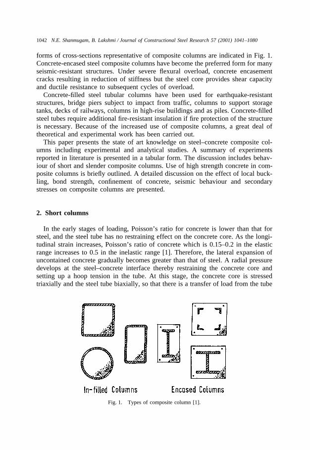
forms of cross-sections representative of composite columns are indicated in Fig. 1.Concrete-encased steel composite columns have become the preferred form for manyseismic-resistant structures. Under severe flexural overload, concrete encasementcracks resulting in reduction of stiffness but the steel core provides shear capacityand ductile resistance to subsequent cycles of overload.
Concrete-filled steel tubular columns have been used for earthquake-resistantstructures, bridge piers subject to impact from traffic, columns to support storagetanks, decks of railways, columns in high-rise buildings and as piles. Concrete-filledsteel tubes require additional fire-resistant insulation if fire protection of the structureis necessary. Because of the increased use of composite columns, a great deal oftheoretical and experimental work has been carried out.
This paper presents the state of art knowledge on steel–concrete composite col-umns including experimental and analytical studies. A summary of experimentsreported in literature is presented in a tabular form. The discussion includes behav-iour of short and slender composite columns. Use of high strength concrete in com-posite columns is briefly outlined. A detailed discussion on the effect of local buck-ling, bond strength, confinement of concrete, seismic behaviour and secondarystresses on composite columns are presented.
2. Short columns
In the early stages of loading, Poisson’s ratio for concrete is lower than that forsteel, and the steel tube has no restraining effect on the concrete core. As the longi-tudinal strain increases, Poisson’s ratio of concrete which is 0.15–0.2 in the elasticrange increases to 0.5 in the inelastic range [1]. Therefore, the lateral expansion ofuncontained concrete gradually becomes greater than that of steel. A radial pressuredevelops at the steel–concrete interface thereby restraining the concrete core andsetting up a hoop tension in the tube. At this stage, the concrete core is stressedtriaxially and the steel tube biaxially, so that there is a transfer of load from the tube
Fig. 1. Types of composite column [1].
1043N.E. Shanmugam, B. Lakshmi / Journal of Constructional Steel Research 57 (2001) 1041–1080
to the core, as the tube cannot sustain the yield stress longitudinally in the presenceof a hoop tension. The load corresponding to this mode of failure can be considerablygreater than the sum of the steel and concrete, but shear failure may intervene beforethe load transfer is complete [2].
2.1. Interaction diagram
When a short composite column is subjected to a small axial load, the compositesection is capable of supporting a bending moment in excess of its ultimate momentof resistance, Mu. This is similar to the effect of a prestressing force on a reinforcedconcrete section. If the axial force and bending moment are independently appliedto the composite section, it should be noted that the removal of the axial load woulddestabilize the section as the corresponding point on the interaction diagram wouldfall outside the failure envelope. It is, therefore, recommended to consider the cutoff point at M/Mu = 1.0 to form an integral part of the interaction curve [3].
2.2. Axially loaded member
The plastic resistance of the cross-section of a composite column with concentricloading is given by:
Npl.rd � Aafyd � Acfcd � Aszfsd (1)
in which Aa, Ac and Asz are cross-sectional area of structural steel, concrete and
reinforcement respectively in the axial direction; fyd, fcd and fsd are, respectively,design strengths of the corresponding materials. Evidence of an increase in concretestrength is obtained for short circular concrete filled steel tubes but not for shortcolumns constructed from square or rectangular hollow steel tubes filled with con-crete, probably because the concrete is subjected to a complex three dimensionalstate of stress.
3. Slender columns
Slender columns are generally subjected to compression and bending. Failureoccurs when the conditions of stressing under which stable equilibrium is no longerpossible between internal and external forces. At this point, for minimal added strain,the increase in external bending moments is more than that the section can take. Theelastic critical buckling stress of an ideally straight column is written as:
fcr �Ncr
A�p2E
(L/r)2 (2)
This expression is non-dimensionalized as
N �fcr
fy�
1l2 (3)
1044 N.E. Shanmugam, B. Lakshmi / Journal of Constructional Steel Research 57 (2001) 1041–1080
where l �(L/r)lE
(4)
and lE � p�Efy
(5)
where:
Ncr the critical loadA area of cross-sectionL effective lengthfy yield stressE modulus of elasticity andr radius of gyration of the column section
l is called the slenderness factor (to distinguish it from the slenderness ratio). Realcolumns would not support a stress in excess of fy, if the effect of strain hardening isignored. Behaviour of a practical column deviates from that of a similar ideal column,particularly in the range corresponding to 0.3�l�1.5. The presence of residualstresses within the cross-section, rather than the initial imperfections, may governthe design practice. Some measure of the level of residual stresses within the sectioncan be obtained by conducting a stub column test. The resulting non-linear stress–strain curve can be used to obtain the inelastic critical buckling load of a straightcolumn using the tangent modulus formula proposed by Engesser. Conventionaldefinition of a radius of gyration cannot be applied rigorously to non-homogeneousor composite cross-section. An effective radius of gyration for this composite sectionwill be somewhat greater than the larger of values for each material taken separately.In the case of concrete-filled composite columns, critical load of slender columnsare obtained using equivalent radius of gyration and flexural stiffness. Design codesprovide different equations for this equivalent stiffness although same design philo-sophy and data were used as the basis for their formulation.
3.1. P–� effect
P–� effect is more pronounced in longer columns. Behaviour of such columnscould be predicted by the Euler approach, where the effect of initial imperfectionsis neglected. When the length of the column is increased, the relationship betweenthe applied load and the mid-length moment is no longer linear. The lateral displace-ments have an adverse effect on the load-carrying capacity of the column as theygenerate a mid-length secondary moment. As the length of the column is furtherincreased, the secondary bending moment increases significantly and its effectbecomes of prime importance. This causes the column to fail by bending rather thanby compression and leads to an instability problem. The overall stability of a steeltube filled with concrete will be influenced more by the steel tube than by the con-tained concrete.
1045N.E. Shanmugam, B. Lakshmi / Journal of Constructional Steel Research 57 (2001) 1041–1080
4. Experimental studies
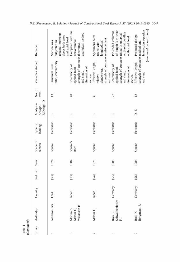
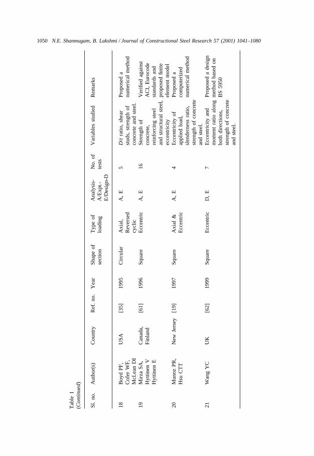
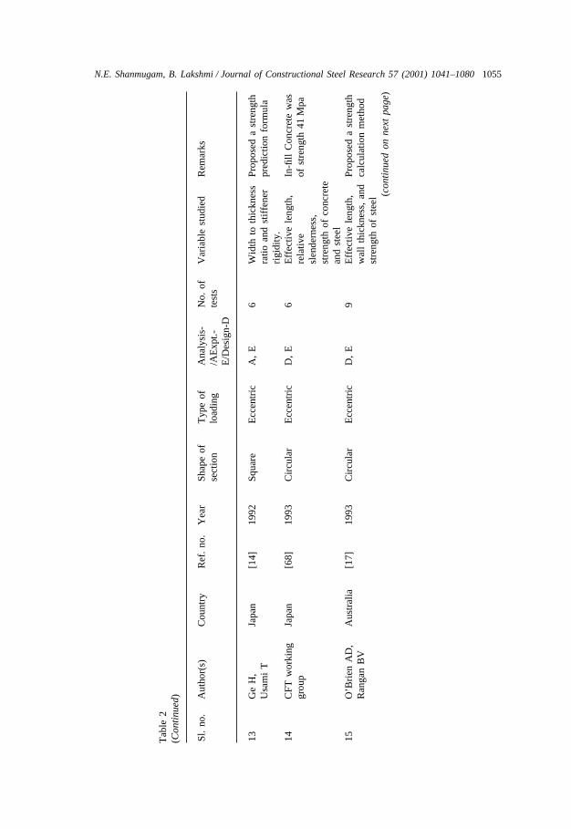
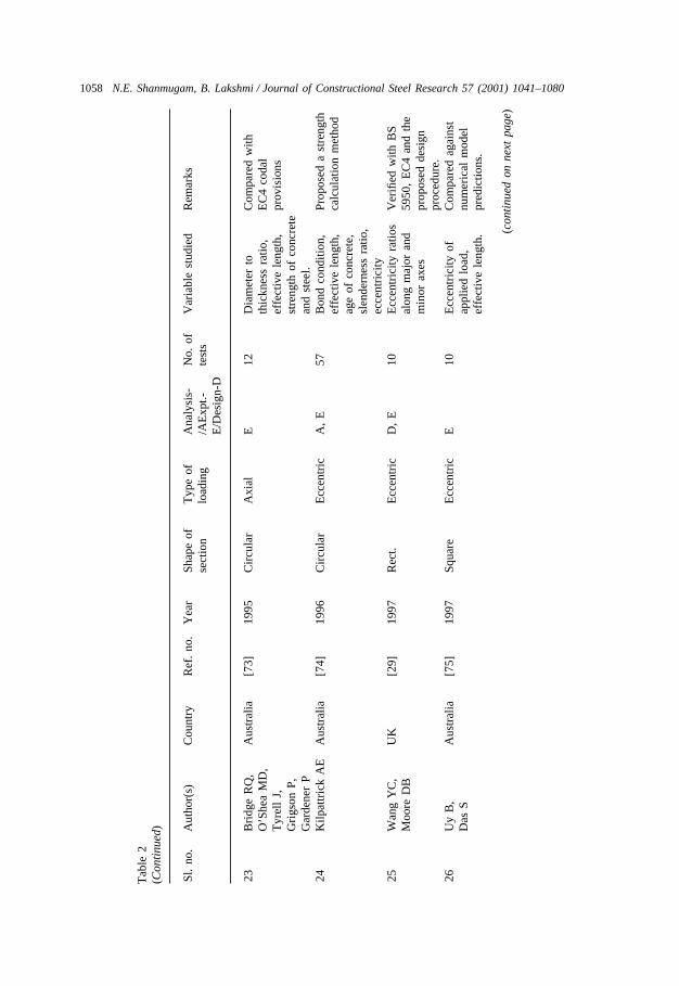
Some of the earlier tests on composite columns were carried out by Burr [4], andwere followed over the years by more experimental and theoretical studies by otherresearchers. Experiments were conducted to obtain basic information to serve as anaid to analyse modeling or to formulate design criteria. The following sectionspresents summary of experiments on both encased and in-filled composite columnstested by various researchers with a view to establish their behaviour and load-carry-ing capacity. Experimental works on both encased and in-filled steel–concrete com-posite columns are listed in Tables 1 and 2, respectively.
4.1. Encased sections
Mirza and Skrabek [5,6] investigated the effect of concrete and steel strengths,the cross-sectional dimensions of concrete and steel section, the presence of steelsection and reinforcing bars on strength of composite column. Two slenderness ratiosof 0 and 21.9 were examined. The other parameter, eccentricity ratio was variedfrom zero to 4 at an interval of 0.05. The results indicated that concrete strength,structural steel ratio, and the end eccentricity ratio influence the statistical propertiesin reliability study of short composite beam-columns. The end eccentricity ratio of0.5 or less are critical since they have a very significant effect on the beam-col-umn strength.
Hunaiti and Fattah [7] investigated the load-carrying capacity of partially encasedcomposite columns subjected to minor axis bending. IPE 200×100×22 steel sectionswith a buckling length of 2.4 m were encased partially in concrete and tested tofailure under eccentric axial load. The variables studied include eccentricity of theapplied load, eccentricity ratio at the column ends, and the effect of concrete strength.In all tests, tension cracks were observed at loads beyond 70% of the failure load.The maximum strength of the columns was obtained by deflection methods usingNewmark’s technique of numerical integration.
4.2. In-filled sections
Tests were conducted on two 47 ft (14 m) long, 13 in (33 cm) diameter pipecolumns, one empty and the other filled with concrete [8]. It was concluded thatconcrete increases the load and moment carrying capacity without increasing the sizeof the column. Experiments on columns with steel tubes of diameter-to-thicknessratio (D/t) of 92 and yield stress of fy in the range of 250–350 MPa, filled withconcrete of characteristic strength fc between 70 and 90 MPa were carried out byPrion and Boehme [9]. The effect of confinement of concrete was noticeable incolumns of slenderness ratio L/D less than 15. No appreciable difference in loadcarrying capacity was detected between long and short specimens and between load-ing on the whole section and on concrete alone.
Rectangular in-filled composite columns of 3 m long were tested under three dif-ferent loading viz. axial, uniaxial bending applied about major or minor axis and

1046 N.E. Shanmugam, B. Lakshmi / Journal of Constructional Steel Research 57 (2001) 1041–1080
Tab
le1
Exp
erim
ents
onen
case
dco
mpo
site
colu
mns
Sl.
no.
Aut
hor(
s)C
ount
ryR
ef.
no.
Yea
rSh
ape
ofT
ype
ofA
naly
sis-
No.
ofV
aria
bles
stud
ied
Rem
arks
sect
ion
load
ing
A/E
xpt.-
test
sE
/Des
ign-
D
1St
even
sR
FU
K[2
4]19
65Sq
uare
&E
ccen
tric
E11
Ecc
entr
icity
ofSp
ecim
ens
wer
eR
ect.
appl
ied
load
,4.
57m
long
and
stre
ngth
ofco
ncre
telo
aded
ecce
ntri
cally
and
stee
l,al
ong
the
wea
kdi
men
sion
ofax
isse
ctio
n.2
Vir
diK
S,U
K[2
1]19
73R
ect.
Ecc
entr
icA
,E
9L
engt
h,ec
cent
rici
tyPr
opos
eda
Dow
ling
PJal
ong
maj
oran
dnu
mer
ical
min
orax
es,
anal
ytic
alm
etho
dco
ncre
test
reng
th3
Ans
lijn
R,
Bel
gium
[51]
1974
Rec
t.E
ccen
tric
E30
Eff
ectiv
ele
ngth
,Sp
ecim
ens
wer
eJa
nss
Jre
lativ
ete
sted
with
out
slen
dern
ess,
long
itudi
nal
stre
ngth
ofco
ncre
tere
info
rcem
ent
and
stee
l,di
men
sion
ofse
ctio
n4
Rod
eric
kJW
,A
ustr
alia
[52]
1975
Rec
t.E
ccen
tric
A,
D,
E15
Ecc
entr
icity
ofPr
opos
eda
stre
ngth
Lok
eY
Oap
plie
dlo
ad,
calc
ulat
ion
met
hod
slen
dern
ess
ratio
.an
dde
sign
proc
edur
e(c
onti
nued
onne
xtpa
ge)
1047N.E. Shanmugam, B. Lakshmi / Journal of Constructional Steel Research 57 (2001) 1041–1080T
able
1(C
onti
nued
)
Sl.
no.
Aut
hor(
s)C
ount
ryR
ef.
no.
Yea
rSh
ape
ofT
ype
ofA
naly
sis-
No.
ofV
aria
bles
stud
ied
Rem
arks
sect
ion
load
ing
A/E
xpt.-
test
sE
/Des
ign-
D
5Jo
hnst
onB
GU
SA[5
3]19
76Sq
uare
Ecc
entr
icE
13St
ruct
ural
stee
lSe
ctio
nw
asra
tio,
ecce
ntri
city
subj
ecte
dto
unia
xial
mom
ents
abou
tbo
thax
esan
dax
ial
load
6M
orin
oS,
Japa
n[1
3]19
84Sq
uare
&E
ccen
tric
E40
Ecc
entr
icity
ofC
ompa
red
with
the
Mat
sui
C,
Rec
t.ap
plie
dlo
ad,
conv
entio
nal
Wat
anab
eH
stre
ngth
ofco
ncre
teth
eore
tical
and
stee
l,an
alyt
ical
met
hod
dim
ensi
onof
sect
ion
7M
atsu
iC
Japa
n[5
4]19
79Sq
uare
Ecc
entr
icE
4E
ffec
tive
leng
th,
Spec
imen
sw
ere
rela
tive
test
edw
ithsl
ende
rnes
s,lo
ngitu
dina
lst
reng
thof
conc
rete
rein
forc
emen
tan
dst
eel
8R
oik
R,
Ger
man
y[5
5]19
89Sq
uare
Ecc
entr
icE
27E
ccen
tric
ityof
Pin-
ende
dco
lum
nsSc
hwal
benh
ofer
appl
ied
load
,of
leng
th3
mw
ere
Kst
reng
thof
conc
rete
test
edin
unia
xial
and
stee
l,or
biax
ial
bend
ing
dim
ensi
onof
with
axia
llo
adse
ctio
n.9
Roi
kK
,G
erm
any
[56]
1984
Squa
reE
ccen
tric
D,
E12
Eff
ectiv
ele
ngth
,Pr
opos
edde
sign
Ber
gman
nR
stre
ngth
ofco
ncre
tem
etho
dan
dan
dst
eel
inte
ract
ion
equa
tion
(con
tinu
edon
next
page
)

1048 N.E. Shanmugam, B. Lakshmi / Journal of Constructional Steel Research 57 (2001) 1041–1080
Tab
le1
(Con
tinu
ed)
Sl.
no.
Aut
hor(
s)C
ount
ryR
ef.
no.
Yea
rSh
ape
ofT
ype
ofA
naly
sis-
No.
ofV
aria
bles
stud
ied
Rem
arks
sect
ion
load
ing
A/E
xpt.-
test
sE
/Des
ign-
D
10M
irza
SA,
Can
ada
[5]
1991
Squa
reE
ccen
tric
A,
D,
E16
Con
cret
est
reng
th,
Com
pare
dw
ithSk
rabe
kB
Wst
ruct
ural
stee
lpr
opos
edde
sign
ratio
,en
dm
etho
dan
dA
CI
ecce
ntri
city
ratio
,st
anda
rds
slen
dern
ess
ratio
11E
lnas
hai
AS,
UK
[57]
1991
Squa
reC
yclic
,A
,E
6T
ype
oflo
adin
gR
esul
tsco
mpa
red
Tak
anas
hiK
,Ps
eudo
and
perc
enta
geof
with
com
pute
rE
lgha
zoul
iA
YD
ynam
icax
ial
load
.pr
ogra
mD
owlin
gPJ
12M
irza
SA,
Can
ada
[6]
1992
Squa
reE
ccen
tric
E16
Stra
in-h
arde
ning
,C
ompa
red
agai
nst
Skra
bek
BW
stre
ngth
ofco
ncre
teA
CI
Bui
ldin
gco
dean
dst
eel,
slen
dern
ess
ratio
s13
Mat
sui
CJa
pan
[43]
1993
Squa
reE
ccen
tric
A,
D,
E6
Eff
ectiv
ele
ngth
,Pr
opos
eda
stre
ngth
rela
tive
calc
ulat
ion
met
hod
slen
dern
ess,
stre
ngth
ofco
ncre
te(c
onti
nued
onne
xtpa
ge)

1049N.E. Shanmugam, B. Lakshmi / Journal of Constructional Steel Research 57 (2001) 1041–1080
Tab
le1
(Con
tinu
ed)
Sl.
no.
Aut
hor(
s)C
ount
ryR
ef.
no.
Yea
rSh
ape
ofT
ype
ofA
naly
sis-
No.
ofV
aria
bles
stud
ied
Rem
arks
sect
ion
load
ing
A/E
xpt.-
test
sE
/Des
ign-
D
14N
akam
ura
TJa
pan
[58]
1994
Squa
reE
ccen
tric
E7
Eff
ectiv
ele
ngth
,R
elat
ive
rela
tive
slen
dern
ess
vari
edsl
ende
rnes
s,fr
om0.
15to
1.0
stre
ngth
ofco
ncre
te15
Hun
aiti
YM
,A
mm
an[7
]19
94R
ect.
Ecc
entr
icA
,D
,E
19E
ccen
tric
ityof
Com
pare
dw
ithFa
ttah
BA
appl
ied
load
,th
eore
tical
load
ofec
cent
rici
tyra
tio,
com
pute
rize
dco
ncre
test
reng
than
alys
isan
dde
sign
load
base
don
BS
5400
16W
ium
JA,
S.A
fric
a,[5
9]19
94Sq
uare
Push
-out
and
A,
D,
E27
Thi
ckne
ssof
Prop
osed
aL
ebet
JPSw
itzer
land
Pull-
out
conc
rete
cove
r,si
mpl
ified
desi
gnam
ount
ofho
opm
etho
dre
info
rcem
ent,
size
ofst
eel
sect
ion,
shri
nkag
eof
conc
rete
.17
Ric
les
JM,
Bet
hleh
em,
[60]
1994
Squa
reSe
ism
icA
,E
8D
egre
eof
conc
rete
Com
pare
dag
ains
tPa
booj
ian
SDC
alif
orni
aco
nfine
men
t,sh
ear
AC
Ian
dA
ISC
-re
sist
ance
LR
FDm
echa
nism
,sp
ecifi
catio
nsst
reng
thof
conc
rete
&st
eel. (c
onti
nued
onne
xtpa
ge)
1050 N.E. Shanmugam, B. Lakshmi / Journal of Constructional Steel Research 57 (2001) 1041–1080
Tab
le1
(Con
tinu
ed)
Sl.
no.
Aut
hor(
s)C
ount
ryR
ef.
no.
Yea
rSh
ape
ofT
ype
ofA
naly
sis-
No.
ofV
aria
bles
stud
ied
Rem
arks
sect
ion
load
ing
A/E
xpt.-
test
sE
/Des
ign-
D
18B
oyd
PF,
USA
[35]
1995
Cir
cula
rA
xial
,A
,E
5D
/tra
tio,
shea
rPr
opos
eda
Cof
erW
F,R
ever
sed
stud
s,st
reng
thof
num
eric
alm
etho
dM
cLea
nD
Icy
clic
conc
rete
and
stee
l.19
Mir
zaSA
,C
anad
a,[6
1]19
96Sq
uare
Ecc
entr
icA
,E
16St
reng
thof
Ver
ified
agai
nst
Hyt
tinen
VFi
nlan
dco
ncre
te,
AC
I,E
uroc
ode
Hyt
tinen
Ere
info
rcin
gst
eel
stan
dard
san
dan
dst
ruct
ural
stee
l,pr
opos
edfin
iteec
cent
rici
tyel
emen
tm
odel
20M
unoz
PR,
New
Jers
ey[1
9]19
97Sq
uare
Axi
al&
A,
E4
Ecc
entr
icity
ofPr
opos
eda
Hsu
CT
TE
ccen
tric
appl
ied
load
,co
mpu
teri
zed
slen
dern
ess
ratio
,nu
mer
ical
met
hod
stre
ngth
ofco
ncre
tean
dst
eel.
21W
ang
YC
UK
[62]
1999
Squa
reE
ccen
tric
D,
E7
Ecc
entr
icity
and
Prop
osed
ade
sign
mom
ent
ratio
alon
gm
etho
dba
sed
onbo
thdi
rect
ions
,B
S59
50st
reng
thof
conc
rete
and
stee
l.

1051N.E. Shanmugam, B. Lakshmi / Journal of Constructional Steel Research 57 (2001) 1041–1080
Tab
le2
Exp
erim
ents
onin
-fille
dco
mpo
site
colu
mns
Sl.
no.
Aut
hor(
s)C
ount
ryR
ef.
no.
Yea
rSh
ape
ofT
ype
ofA
naly
sis-
No.
ofV
aria
ble
stud
ied
Rem
arks
sect
ion
load
ing
/AE
xpt.-
test
sE
/Des
ign-
D
1N
eogi
PR,
UK
[2]
1969
Cir
cula
rE
ccen
tric
A,
E18
D/t
ratio
,Pr
opos
eda
Sen
HK
,sl
ende
rnes
sra
tio,
com
pute
rise
dC
hapm
anJC
stre
ngth
ofco
ncre
tenu
mer
ical
met
hod
and
stee
l,ec
cent
rici
ty2
Kno
wle
sR
B,
New
[30]
1969
Cir
cula
r&
Axi
al&
A,
E28
Stre
ngth
ofPr
opos
edan
Park
RZ
eala
ndSq
uare
Ecc
entr
icco
ncre
tean
dst
eel,
anal
ytic
alm
etho
dsl
ende
rnes
sra
tio3
Dry
sdal
eR
G,
Can
ada
[63]
1971
Squa
reE
ccen
tric
A,
E58
Stre
ngth
ofPr
opos
eda
Hug
gins
MW
conc
rete
and
stee
l,nu
mer
ical
met
hod
load
ing
sequ
ence
,du
ratio
nof
load
ing,
ecce
ntri
city
(con
tinu
edon
next
page
)

1052 N.E. Shanmugam, B. Lakshmi / Journal of Constructional Steel Research 57 (2001) 1041–1080
Tab
le2
(Con
tinu
ed)
Sl.
no.
Aut
hor(
s)C
ount
ryR
ef.
no.
Yea
rSh
ape
ofT
ype
ofA
naly
sis-
No.
ofV
aria
ble
stud
ied
Rem
arks
sect
ion
load
ing
/AE
xpt.-
test
sE
/Des
ign-
D
4B
ridg
eR
QA
ustr
alia
[64]
1976
Squa
reE
ccen
tric
A,
D,
E8
D/t
ratio
,Pr
opos
edan
slen
dern
ess
ratio
,an
alyt
ical
met
hod
stre
ngth
ofco
ncre
tean
dco
mpa
red
with
and
stee
l,te
stre
sults
ecce
ntri
city
ratio
,in
clin
atio
nof
load
ing
axis
.5
Tas
kG
roup
USA
[22]
1979
Cir
cula
rE
ccen
tric
D,
E51
Eff
ectiv
ele
ngth
,Sh
ort
sect
ion
wer
e20
SSR
Cre
lativ
esu
bjec
ted
tosl
ende
rnes
s,un
iaxi
alm
omen
tsst
reng
thof
conc
rete
abou
tbo
thax
esan
dst
eel,
and
axia
llo
addi
men
sion
sof
tube
.6
Sasa
kiR
Japa
n[6
5]19
84C
ircu
lar
Ecc
entr
icD
,E
21E
ffec
tive
leng
th,
Hig
hst
reng
thre
lativ
eco
ncre
te(5
3M
Pa–
slen
dern
ess,
63M
Pa)
was
used
stre
ngth
ofco
ncre
teas
in-fi
llan
dst
eel
(con
tinu
edon
next
page
)

1053N.E. Shanmugam, B. Lakshmi / Journal of Constructional Steel Research 57 (2001) 1041–1080
Tab
le2
(Con
tinu
ed)
Sl.
no.
Aut
hor(
s)C
ount
ryR
ef.
no.
Yea
rSh
ape
ofT
ype
ofA
naly
sis-
No.
ofV
aria
ble
stud
ied
Rem
arks
sect
ion
load
ing
/AE
xpt.-
test
sE
/Des
ign-
D
7Pr
ion
HG
L,
Can
ada
[9]
1989
Cir
cula
rE
ccen
tric
A,
E20
Met
hod
oflo
adin
g,D
evel
oped
anB
oehm
eJ
leng
th,
stre
ngth
ofan
alyt
ical
met
hod.
conc
rete
and
stee
l8
Shak
irK
halil
H,
UK
[10]
1989
Rec
t.E
ccen
tric
A,
E7
Stre
ngth
ofC
ompa
red
with
Zeg
hich
eJ
conc
rete
and
stee
l,fin
iteel
emen
tec
cent
rici
tyra
tio.
anal
ysis
and
BS
5400
.9
Shak
irK
halil
H,
UK
[11]
1990
Rec
t.A
xial
&E
9C
olum
nse
ctio
n,C
ompa
red
agai
nst
Mou
liM
Ecc
entr
icec
cent
rici
tyra
tio,
BS
5950
&B
Sef
fect
ive
leng
th,
5400
prov
isio
ns.
stre
ngth
ofco
ncre
tean
dst
eel.
(con
tinu
edon
next
page
)

1054 N.E. Shanmugam, B. Lakshmi / Journal of Constructional Steel Research 57 (2001) 1041–1080
Tab
le2
(Con
tinu
ed)
Sl.
no.
Aut
hor(
s)C
ount
ryR
ef.
no.
Yea
rSh
ape
ofT
ype
ofA
naly
sis-
No.
ofV
aria
ble
stud
ied
Rem
arks
sect
ion
load
ing
/AE
xpt.-
test
sE
/Des
ign-
D
10K
onno
H,
Japa
n[6
6]19
90Sq
uare
Ecc
entr
icD
,E
19T
hick
ness
ofst
eel
Con
finem
ent
effe
ctK
eiT
,tu
be,
stre
ngth
ofac
coun
ted
inN
agas
him
aT
.co
ncre
tean
dst
eel,
prop
osed
stre
ngth
and
ratio
ofax
ial
estim
atio
nm
etho
dfo
rce.
11C
aiSH
Japa
n[6
7]19
91C
ircu
lar
Ecc
entr
icA
,E
27E
ffec
tive
leng
th,
Col
umn
wer
est
reng
thof
conc
rete
subj
ecte
dto
both
and
stee
l,si
ngle
and
doub
leec
cent
rici
tyof
curv
atur
ebe
ndin
gap
plie
dlo
ad12
Ran
gan
BV
,A
ustr
alia
[16]
1992
Cir
cula
rE
ccen
tric
D,
E9
Slen
dern
ess
ratio
,Pr
opos
eda
stre
ngth
Joyc
eM
ecce
ntri
city
ofax
ial
calc
ulat
ion
met
hod
thru
st(c
onti
nued
onne
xtpa
ge)
1055N.E. Shanmugam, B. Lakshmi / Journal of Constructional Steel Research 57 (2001) 1041–1080
Tab
le2
(Con
tinu
ed)
Sl.
no.
Aut
hor(
s)C
ount
ryR
ef.
no.
Yea
rSh
ape
ofT
ype
ofA
naly
sis-
No.
ofV
aria
ble
stud
ied
Rem
arks
sect
ion
load
ing
/AE
xpt.-
test
sE
/Des
ign-
D
13G
eH
,Ja
pan
[14]
1992
Squa
reE
ccen
tric
A,
E6
Wid
thto
thic
knes
sPr
opos
eda
stre
ngth
Usa
mi
Tra
tioan
dst
iffe
ner
pred
ictio
nfo
rmul
ari
gidi
ty.
14C
FTw
orki
ngJa
pan
[68]
1993
Cir
cula
rE
ccen
tric
D,
E6
Eff
ectiv
ele
ngth
,In
-fill
Con
cret
ew
asgr
oup
rela
tive
ofst
reng
th41
Mpa
slen
dern
ess,
stre
ngth
ofco
ncre
tean
dst
eel
15O
’Bri
enA
D,
Aus
tral
ia[1
7]19
93C
ircu
lar
Ecc
entr
icD
,E
9E
ffec
tive
leng
th,
Prop
osed
ast
reng
thR
anga
nB
Vw
all
thic
knes
s,an
dca
lcul
atio
nm
etho
dst
reng
thof
stee
l (con
tinu
edon
next
page
)

1056 N.E. Shanmugam, B. Lakshmi / Journal of Constructional Steel Research 57 (2001) 1041–1080
Tab
le2
(Con
tinu
ed)
Sl.
no.
Aut
hor(
s)C
ount
ryR
ef.
no.
Yea
rSh
ape
ofT
ype
ofA
naly
sis-
No.
ofV
aria
ble
stud
ied
Rem
arks
sect
ion
load
ing
/AE
xpt.-
test
sE
/Des
ign-
D
16Fu
jiR
Japa
n[6
9]19
94C
ircu
lar
Ecc
entr
icA
,E
33D
/tra
tio,
stre
ngth
Ver
ified
with
ofco
ncre
tean
dpr
opos
edst
reng
thst
eel,
effe
ctiv
eca
lcul
atio
nm
etho
dle
ngth
.an
dE
C4.
17K
ilpat
rick
AE
Aus
tral
ia[7
0]19
94C
ircu
lar
Ecc
entr
icA
,E
16D
/tra
tio,
stre
ngth
Ver
ified
with
ofco
ncre
tean
dpr
opos
edst
reng
thst
eel,
effe
ctiv
eca
lcul
atio
nm
etho
dle
ngth
.an
dE
C4.
18Sh
akir
-Kha
lilH
,U
K[1
2]19
94R
ect.
Axi
al&
A,
E15
Eff
ectiv
ele
ngth
,A
BA
QU
Sso
ftw
are
Al-
Raw
dan
AE
ccen
tric
ecce
ntri
city
ofpa
ckag
ew
asus
edap
plie
dlo
ad,
and
tove
rify
resu
ltsst
reng
thof
conc
rete
and
stee
l(c
onti
nued
onne
xtpa
ge)

1057N.E. Shanmugam, B. Lakshmi / Journal of Constructional Steel Research 57 (2001) 1041–1080
Tab
le2
(Con
tinu
ed)
Sl.
no.
Aut
hor(
s)C
ount
ryR
ef.
no.
Yea
rSh
ape
ofT
ype
ofA
naly
sis-
No.
ofV
aria
ble
stud
ied
Rem
arks
sect
ion
load
ing
/AE
xpt.-
test
sE
/Des
ign-
D
19H
ayas
hiN
,Ja
pan
[71]
1995
Squa
reD
ispl
.D
,E
10W
idth
toth
ickn
ess
Prop
osed
ast
reng
thIn
one
T,
cont
rolle
dra
tio,
axia
lfo
rce
calc
ulat
ion
met
hod
Fuku
mot
oT
,ra
tio,
stre
ngth
ofU
kada
T,
conc
rete
and
stee
l.A
kiya
ma
H20
Kim
WJ,
Kor
ea[7
2]19
95C
ircu
lar
Axi
alD
,E
14D
iam
eter
toPr
opos
edan
Park
JM,
thic
knes
sra
tio,
empi
rica
lfo
rmul
aeO
hY
Slo
adin
gco
nditi
on,
topr
edic
tul
timat
est
reng
thof
conc
rete
capa
city
.an
dst
eel
21M
atsu
iC
,Ja
pan
[49]
1995
Cir
cula
r&A
xial
&A
,D
,E
24B
uckl
ing
leng
th,
Prop
osed
ade
sign
Tsu
daK
,Sq
uare
Ecc
entr
icse
ctio
nde
pth,
met
hod
Ishi
bash
iY
ecce
ntri
city
ofap
plie
dlo
ad,
slen
dern
ess
ratio
.22
O’S
hea
MD
,A
ustr
alia
[18]
1995
Cir
cula
rA
xial
&E
10D
iam
eter
toC
ompa
red
with
Bri
dge
RQ
Ecc
entr
icth
ickn
ess
ratio
,E
C4
coda
lef
fect
ive
leng
th,
prov
isio
nsst
reng
thof
conc
rete
and
stee
l.(c
onti
nued
onne
xtpa
ge)
1058 N.E. Shanmugam, B. Lakshmi / Journal of Constructional Steel Research 57 (2001) 1041–1080
Tab
le2
(Con
tinu
ed)
Sl.
no.
Aut
hor(
s)C
ount
ryR
ef.
no.
Yea
rSh
ape
ofT
ype
ofA
naly
sis-
No.
ofV
aria
ble
stud
ied
Rem
arks
sect
ion
load
ing
/AE
xpt.-
test
sE
/Des
ign-
D
23B
ridg
eR
Q,
Aus
tral
ia[7
3]19
95C
ircu
lar
Axi
alE
12D
iam
eter
toC
ompa
red
with
O’S
hea
MD
,th
ickn
ess
ratio
,E
C4
coda
lT
yrel
lJ,
effe
ctiv
ele
ngth
,pr
ovis
ions
Gri
gson
P,st
reng
thof
conc
rete
Gar
dene
rP
and
stee
l.24
Kilp
attr
ick
AE
Aus
tral
ia[7
4]19
96C
ircu
lar
Ecc
entr
icA
,E
57B
ond
cond
ition
,Pr
opos
eda
stre
ngth
effe
ctiv
ele
ngth
,ca
lcul
atio
nm
etho
dag
eof
conc
rete
,sl
ende
rnes
sra
tio,
ecce
ntri
city
25W
ang
YC
,U
K[2
9]19
97R
ect.
Ecc
entr
icD
,E
10E
ccen
tric
ityra
tios
Ver
ified
with
BS
Moo
reD
Bal
ong
maj
oran
d59
50,
EC
4an
dth
em
inor
axes
prop
osed
desi
gnpr
oced
ure.
26U
yB
,A
ustr
alia
[75]
1997
Squa
reE
ccen
tric
E10
Ecc
entr
icity
ofC
ompa
red
agai
nst
Das
Sap
plie
dlo
ad,
num
eric
alm
odel
effe
ctiv
ele
ngth
.pr
edic
tions
.
(con
tinu
edon
next
page
)

1059N.E. Shanmugam, B. Lakshmi / Journal of Constructional Steel Research 57 (2001) 1041–1080T
able
2(C
onti
nued
)
Sl.
no.
Aut
hor(
s)C
ount
ryR
ef.
no.
Yea
rSh
ape
ofT
ype
ofA
naly
sis-
No.
ofV
aria
ble
stud
ied
Rem
arks
sect
ion
load
ing
/AE
xpt.-
test
sE
/Des
ign-
D
27T
hiru
gnan
a-A
ustr
alia
[76]
1997
Cir
cula
rSt
atic
&E
8E
ccen
tric
ityof
Prop
osed
ast
reng
thsu
ndra
linga
mK
,V
aria
ble
appl
ied
load
,ca
lcul
atio
nm
etho
dT
haya
lan
P,re
peat
edco
ncre
test
reng
th.
Patn
aiku
niI
load
ing
28K
awan
oA
,Ja
pan
[77]
1997
Cir
cula
rC
yclic
A,
E44
Slen
dern
ess
ratio
,Pr
opos
edan
Mat
sui
CD
/tra
tio,
stre
ngth
empi
rica
lde
sign
ofco
ncre
tean
deq
uatio
n.st
eel.
29U
yB
Aus
tral
ia[4
7]19
98Sq
uare
Dis
pl.
A,
E10
Dim
ensi
ons
ofC
ompa
red
with
cont
rolle
dse
ctio
n,m
etho
dof
prop
osed
anal
ysis
load
ing,
resi
dual
met
hod
and
AS
stre
ss41
00&
BS
5950
code
s.30
Wan
gY
CU
K[6
2]19
99R
ect.
Ecc
entr
icD
,E
8E
ccen
tric
ityan
dPr
opos
eda
desi
gnm
omen
tra
tioal
ong
proc
edur
eba
sed
onbo
thdi
rect
ions
,B
S59
50.
stre
ngth
ofco
ncre
tean
dst
eel.
31N
akan
ishi
K,
Japa
n[3
7]19
99Sq
uare
Seis
mic
E8
Cro
ss-s
ectio
n,Pr
opos
edan
Nak
aiH
,st
reng
thof
stee
lem
piri
cal
desi
gnK
itada
Tan
dco
ncre
te,
equa
tion.
natu
ral
peri
odof
vibr
atio
n.

1060 N.E. Shanmugam, B. Lakshmi / Journal of Constructional Steel Research 57 (2001) 1041–1080
biaxial bending [10]. Effect of end eccentricity ratios ex/D and ey/D up to 0.5 wasalso studied. In most columns, the yield strain was reached in the compressive zonesat loads varying between 80% and 90% of the failure load. After the failure, thetensile strains reached the yield as the columns underwent large lateral displacementsand consequently were subjected to high bending moments. It was concluded thatthe failure mode of all columns was an overall buckling mode, with no sign of localbuckling of the steel section. Further tests on rectangular in-filled steel tubes byShakir-Khalil and Mouli [11] showed that concrete filling increases considerably theload carrying capacity of the column. In addition to varying the column section, theeffects of varying the design strength of steel, the cube strength of concrete and thecolumn length were also investigated. The relative carrying capacity of compositeto steel column increases when the size of the steel section is increased and withthe use of high strength concrete.
Failure loads and load–displacement relationships up to and beyond failure ofconcrete-filled composite columns of 3, 4 and 5 m were analysed using the softwareABAQUS by Shakir-Khalil and Rawdan [12]. Tensile strength of the concrete wastaken as 10% of the compressive strength in bending. i.e. 0.06fcu. Results of anexperimental study on the elasto-plastic behaviour of steel reinforced concrete (SRC)columns subjected to biaxially eccentric compression showed that a sharp peakappears on the load–deflection curve of a short column because of a concrete crush,while P–� effect was more pronounced in a long column and a gradual unloadingtakes place [13].
4.3. Failure modes
Short composite columns exhibit a failure mechanism characterized by yieldingof steel and crushing of concrete. Medium length columns behave inelastically andfail by partial yielding of steel, crushing of concrete in compression and crackingof concrete in tension. When the load applied to a column is eccentric in the strongerplane of bending and the slenderness for buckling in that plane is much less than thatfor minor-axis buckling, failure in a biaxial mode is possible. In columns subjected tobiaxial bending, the neutral axis changes its position continuously by a combinationof translation and rotation. Stiffness along the whole length of the column variesdue to an uncracked concrete section near the ends with an increasing frequency ofcracking nearer the center. Ge and Usami [14] studied local buckling modes of stiff-ened and unstiffened in-filled columns shown in Fig. 2.
Fig. 2. Buckling modes of steel and composite sections [14].
1061N.E. Shanmugam, B. Lakshmi / Journal of Constructional Steel Research 57 (2001) 1041–1080
The stiffeners contributed largely to the overall buckling of columns even whenstiffener rigidities were small, local buckling of longitudinal stiffeners being pre-vented by the concrete. In case of steel box columns, the local buckling of platepanels occurred before the maximum load. It was observed in composite columnsthat local plate buckling occurred initially in one of the plates of the columns justbefore the maximum load was reached, and the other buckling deformations tookplace in the remaining plates after peak. In addition, increase in deformationsbecomes faster after local buckling and cracks in weld occurred in some of concrete-filed columns.
5. Use of high strength concrete in composite columns
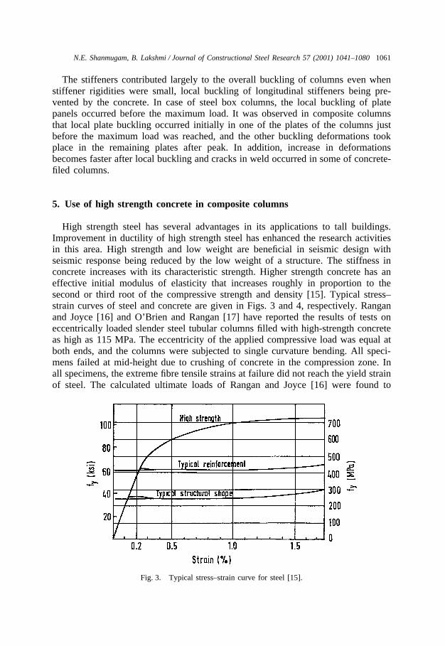
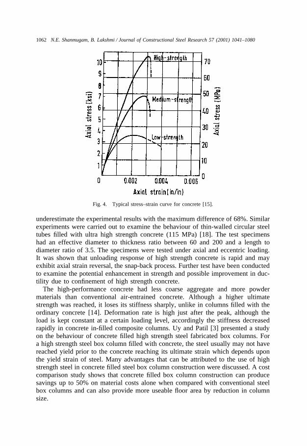
High strength steel has several advantages in its applications to tall buildings.Improvement in ductility of high strength steel has enhanced the research activitiesin this area. High strength and low weight are beneficial in seismic design withseismic response being reduced by the low weight of a structure. The stiffness inconcrete increases with its characteristic strength. Higher strength concrete has aneffective initial modulus of elasticity that increases roughly in proportion to thesecond or third root of the compressive strength and density [15]. Typical stress–strain curves of steel and concrete are given in Figs. 3 and 4, respectively. Ranganand Joyce [16] and O’Brien and Rangan [17] have reported the results of tests oneccentrically loaded slender steel tubular columns filled with high-strength concreteas high as 115 MPa. The eccentricity of the applied compressive load was equal atboth ends, and the columns were subjected to single curvature bending. All speci-mens failed at mid-height due to crushing of concrete in the compression zone. Inall specimens, the extreme fibre tensile strains at failure did not reach the yield strainof steel. The calculated ultimate loads of Rangan and Joyce [16] were found to
Fig. 3. Typical stress–strain curve for steel [15].
1062 N.E. Shanmugam, B. Lakshmi / Journal of Constructional Steel Research 57 (2001) 1041–1080
Fig. 4. Typical stress–strain curve for concrete [15].
underestimate the experimental results with the maximum difference of 68%. Similarexperiments were carried out to examine the behaviour of thin-walled circular steeltubes filled with ultra high strength concrete (115 MPa) [18]. The test specimenshad an effective diameter to thickness ratio between 60 and 200 and a length todiameter ratio of 3.5. The specimens were tested under axial and eccentric loading.It was shown that unloading response of high strength concrete is rapid and mayexhibit axial strain reversal, the snap-back process. Further test have been conductedto examine the potential enhancement in strength and possible improvement in duc-tility due to confinement of high strength concrete.
The high-performance concrete had less coarse aggregate and more powdermaterials than conventional air-entrained concrete. Although a higher ultimatestrength was reached, it loses its stiffness sharply, unlike in columns filled with theordinary concrete [14]. Deformation rate is high just after the peak, although theload is kept constant at a certain loading level, accordingly the stiffness decreasedrapidly in concrete in-filled composite columns. Uy and Patil [3] presented a studyon the behaviour of concrete filled high strength steel fabricated box columns. Fora high strength steel box column filled with concrete, the steel usually may not havereached yield prior to the concrete reaching its ultimate strain which depends uponthe yield strain of steel. Many advantages that can be attributed to the use of highstrength steel in concrete filled steel box column construction were discussed. A costcomparison study shows that concrete filled box column construction can producesavings up to 50% on material costs alone when compared with conventional steelbox columns and can also provide more useable floor area by reduction in columnsize.

1063N.E. Shanmugam, B. Lakshmi / Journal of Constructional Steel Research 57 (2001) 1041–1080
6. Analytical studies
Ultimate load of a column can be defined as the highest load for which an equilib-rium-deflected shape can be obtained, in other words the load at which the columnstiffness becomes zero. Principal factors that make the determination of the ultimateload complicated are the non-linear material characteristics of both concrete andsteel, geometrical imperfections and residual stresses in the steel section. It involvessub-division of the cross-section into a number of slices to allow the strain distri-bution to be idealized as a unique linear function. The forces in each slice may thenbe established and integrated to obtain the axial force. When the axial force con-verges to the applied load, the neutral axis is then defined. A typical strain distri-bution over the cross-section is characterized by the strain at the top fibre and thecurvature. To analyse a section is to establish a load–moment interaction curve.Intersection of the loading line for an eccentrically loaded column with the strengthenvelope is then taken as the ultimate load. Ultimate strength of composite columnshas been the subject of many investigations. A wide range of analytical methods areformulated to examine the applicability of composite columns under various loadingconditions, summary of which is presented below.
6.1. Encased sections
Furlong [15] attempted to correlate an elliptical form of an interaction diagrambetween the axial load and moment and found the elliptical form too conservative.It was concluded that interaction function derived from the rules of the ordinaryreinforced concrete ultimate shear strength approach is more reasonable. The flexuraland axial stiffness were derived as an algebraic sum of stiffness of each componentpart as if they acted separately.
The finite difference method was employed by Munoz and Thomas Hsu [19] toestablish the relationship between curvature and deflection. The effect of creep, twist-ing effects, axial and shear deformation and tensile stresses due to shrinkage wasneglected. In addition, the initial imperfection and residual stresses were notincluded. Finite difference method in combination with the secant stiffness matrixwas used to solve the system of nonlinear equations. Also design equation to predictthe ultimate load capacity of short and slender concrete-encased square and rectangu-lar composite columns under uniaxial and biaxial bending was proposed [20]. Thedesign equation satisfied basic analytical and design parameters of both the AmericanConcrete Institute (ACI) and the American Institute of Steel Construction (AISC).The second order effects on slender columns were considered by incorporating amoment magnification factor similar to the one used by the ACI for reinforced con-crete columns with the appropriate adjustments for rectangular composite col-umns.The proposed uniaxial interaction equation is:
�Pn�Pnb
P0�Pnb�a � �Mn
Mnb� � 1 (6)
where a varies from 1 to 3; Mn and Pn refer to a typical point in uniaxial interaction

1064 N.E. Shanmugam, B. Lakshmi / Journal of Constructional Steel Research 57 (2001) 1041–1080
diagram; Mnb and Pnb correspond to balanced condition and P0 the maximumaxial load.
An analytical method for computing the ultimate failure loads of encased com-posite columns, subjected to an axial load and biaxial end moments was presentedby Virdi and Dowling [21]. As an integral part of the procedure, a rapid method ofestablishing the moment–curvature–thrust relations was described. The efficiency ofthe method stems from the use of gauss quadrature formulae. A second-order iter-ation technique, the generalized Newton-Raphson method, has been adopted to evalu-ate the deflection of the column at evenly spaced points along the column length. Theultimate load was obtained by establishing the highest load for which equilibrium atdeflected shape can be obtained. Task Group 20 [22] of the Structural StabilityResearch Council (SSRC) proposed a specification for the design of steel–concretecomposite columns in 1979, which was subsequently adopted in the 1986 AISC-LRFD code. This specification requires that steel-encased concrete sections bedesigned in a way that is similar to the design of steel columns, with modificationsto the steel yield strength, modulus of elasticity, and radius of gyration to accountfor the effect of concrete and longitudinal bars. The specification also places limi-tations on the percentage area of steel, concrete strength and minimum thickness ofthe steel shell. The minimum thickness for steel shells in circular composite columnsis calculated using the equation:
t�� fy8Es
(7)
where fy and Es are the steel yield stress and modulus of elasticity, respectively.Roik and Bergmann [23] proposed a design method for composite columns with
unsymmetrical cross-sections. The method is applicable to cases of axial-com-pression and combined compression and bending. It was based on the simplifiedmethod for composite columns with symmetrical cross-sections given in Eurocode4. However, the cross-sectional properties have to be calculated with respect to theelastic centroidal axis and the action effects with respect to the plastic centroidal axis.
A study into stiffening and strengthening effects obtained from a concreteencasement was reported by Stevens [24] who suggested a straight line interactionformula for the strength of beam-columns. The column curve generated by tests werecompared with that of a reinforced column and it was concluded that due to thesimilarity in the behaviour of reinforced and encased columns, similar principles canbe applied to the design concept.
Basu and Sommerville [25] carried out a theoretical study on large number ofaxially loaded composite columns and obtained a curve lying below the Perry-Rob-ertson curve. Although the curve is satisfactory for practical purposes, it should benoted that, for large values of slenderness ratio, it implies that an encased sectionmay have a lower capacity than the corresponding encased section. Roberts and Yam[26] suggest the use of an elliptic contour interaction surface for composite columns:
(Mx/Mxu)2 � (My/Myu)2�1 (8)

1065N.E. Shanmugam, B. Lakshmi / Journal of Constructional Steel Research 57 (2001) 1041–1080
where Mx and My are the bending moments about x- and y-axes respectively. Mxu
and Myu refer to the ultimate moment of resistance about their corresponding axes.
6.2. In-filled sections
Strength calculation method proposed by Rangan and Joyce [16] assumed a sinefunction for the deflection of the column. In addition, the axial load capacity Pu ofa slender eccentrically loaded steel tubular column filled with concrete was assumedto reach when the maximum moment Mu is equal to the ultimate bending momentMn at the mid-height of the column. Deflection due to creep and imperfections insteel tube were treated as an additional eccentricity. Calculations of creep deflectionare given as follows:
Creep deflection �cp � �tot��e (9)
where �tot �e
��Pc
Pf��1� (10)
�e �e
��Pco
Pf��1� (11)
in which
Pc � p2EI/L2 (12)
Pco � p2EIgt/L2 (13)
Pf is the axial thrust due to sustained loads; L is the effective length of a column,
EI � EcIgt/(1 � 0.8fcc) (14)
EcIgt is the bending stiffness of the transformed uncracked concrete section of thecolumn at mid height. fcc is the creep factor which is the ratio of creep strain toelastic strain in concrete.
Bradford [27] proposed the following load–moment interaction curve assumingthe position of the ultimate neutral axis as a parameter.
fMs
fM0� 1 � 2�fNs
fN0��3�fNs
fN0�a (15)
in which
a � 1.0 � 0.5l; (16)
l �0.85(b�2t)(d�2t)f�c
2(b � d�2t)tsy; (17)
fMs is the column central moment, fNs the corresponding strength to fMs, fM0 thefactored design strength in pure bending and fN0 the factored axial strength.

1066 N.E. Shanmugam, B. Lakshmi / Journal of Constructional Steel Research 57 (2001) 1041–1080
f the resistance factor and index a was obtained by matching the approximatecurve for several different sections through assumed balance point. The method wasfound conservative compared to the test results.
A design formula with an empirical reduction factor that accounts for the effectof in-filled concrete prism size and the concrete strength class was proposed by Geand Usami [28]. A hardening–softening model was used to describe rationally theelasto-plastic behaviour of concrete. Contact element for the interface combined withbilinear constrained shell elements for the plate and a cubic element for the concretewas employed. Both initial geometrical imperfections and residual stresses were alsoconsidered in the plate elements.
Local buckling strength of the plate panel in composite columns was then com-pared with available empirical design formulae for a thin-walled steel member incompression. Longitudinal stiffeners were identified to be effective against localbuckling of plate panel. Stiffening effect tends to increase due to the bonding betweenthe stiffener and concrete [14].
Wang and Moore [29] developed a simple design procedure suitable for manualcalculation by replacing the properties of the bare steel section with those of thecomposite section, based on the recommendations given in BS 5950 for bare steelcolumn. Though the proposed method was conservative, the simplicity was perhapsa major factor in its favour. In this method, there are two equations:one for localbuckling capacity check:
NNu
�Mx
Mcx
�My
Mcy
�1 (18)
and the other for global buckling check:
mMx
Max
�mMy
May
�1 (19)
Max and May in the above equation are the reduced column maximum bucklingmoments about the major and minor axis respectively, in the presence of the axialload N. The values of these moment resistance can be related to the column plasticmoment capacities Mcx and Mcy and the column compression resistance Ncx and Ncy
in the following way:
Max � Mcx
1�N
Ncx
1 �0.5NNcx
(20)
May � Mcy
1�N
Ncy
1 �0.5NNcy
(21)
In the above equations which follow the approach given in BS 5950, the values of
1067N.E. Shanmugam, B. Lakshmi / Journal of Constructional Steel Research 57 (2001) 1041–1080
Nu, Mcx, Mcy, Ncx and Ncy correspond to composite column. Wang used column-buckling curves ‘a’ for concrete-filled columns, ‘b’ for concrete encased columnsbending about the major axis and ‘c’ for concrete encased columns bending aboutthe minor axis. Composite cross-section is transformed to an equivalent steel section.Area As and the second moment of inertia, ‘ I’ of the equivalent steel section aregiven as:
As �Nu
Pys/gs(22)
I � Is � Ic
0.67Ec/rc
Es/rs(23)
in which the subscripts ‘s’ and ‘c’ refer to steel and concrete components, respect-ively, and Ic is the second moment of inertia of the untracked concrete component.Factor 0.67 relates the uniform rectangular stress block to the concrete cube strength.
The elasto-plastic behaviour of pin-ended, concrete-filled tubular steel columnssubjected to axial or uniaxial load was studied numerically by Neogi et al. [2]. Thetriaxial and biaxial effects of concrete were not considered. The concentrically loadedstraight column was analysed by the tangent-modulus approach, whereas the eccen-trically loaded column was analysed by determining the ‘exact’ deflected shape orby assuming the shape to be part of a cosine wave. Central deflection i.e., deflectionat mid-height is related directly to the central curvature as:
r0 � �4l2�cos�1� e
e � d0��2
·(e � d0) (24)
where d0 and r0 stand for the central deflection and curvature respectively; e—eccen-tricity of load, and l—effective length of the column. Good agreement was observedbetween the experimental and theoretical behaviour of columns with l/d ratios greaterthan 15. It was concluded that the triaxial effect diminishes as the eccentricityincreases.
A straight line interaction formula proposed by Knowles and Park [30] is anapproximation which may be unsafe for slender columns and conservative for shortcolumns. Experimental behaviour of hollow and concrete filled steel tubular columnsappears similar without any reflection of concrete filling. Ben Kato [31] proposedthe following design formulae based on ISO standards with appropriate modificationsfor both encased and in-filled column. Buckling strength of centrally loaded concrete-filled steel tubular columns is given by,
Nc � gNy (25)
Ny � Assy � bAcfc � (arsyr) (26)
b = 1.1 for circular sectionsb = 1.0 for square sections.
g � B(1�√1�C) (27)

1068 N.E. Shanmugam, B. Lakshmi / Journal of Constructional Steel Research 57 (2001) 1041–1080
B �1 � 0.34(l�0.2) � l2
2l2 (28)
C � (Bl)�2 (29)
l �kLp�
Assy � bAcfcEIs � EcIc
(30)
and for concrete-encased steel columns
Ny � Assy � 0.8Acfc � (arsyr) (31)
l �kLp�
Assy � 0.8Acfc � (arsyr)EIs � (EIr) � EcIc
(32)
In the above equations, As—sectional area of steel section; Ac—area of concrete;fc—compressive strength of concrete; kL—effective length of column; Es—modulusof elasticity of steel; Is—moment of inertia of steel section; sy—yield stress of steel;ar—area of longitudinal reinforcing bars for concrete-encased steel column; syr—yield stress of longitudinal reinforcing bars for concrete-encased steel column; Ir—moment of inertia of longitudinal reinforcing bars; Ic—moment of inertia of concrete;Ec—modulus of elasticity of concrete.
However, limited experimental and analytical methods on the response of high-strength steel tubes filled with high-strength concrete to short term loading are avail-able. Effects of parameters such as slenderness, confinement, reinforcement andimperfections in the shape of the tube on the ultimate strength of composite sectionare to be investigated rigorously.
7. Shear resistance and bond strength
The use of mechanical connectors may be necessary in special circumstances inwhich the limiting bond stress is likely to be exceeded for example in the presenceof significant transverse shear on the column, and also in the case of dynamic andseismic loading. For a smooth steel surface, the mechanical resistance is of lessimportance than for an embossed or irregular steel surface. The influence of an inter-face pressure on the force transfer is therefore more important for a smooth steelsurface found in composite columns than for a surface with embossments or irregu-larities. Plain concrete without reinforcement will have no shear strength after eitherflexural or shear cracking, unless it is confined inside relatively short length of steeltube or pipe.
Suzuki and Kate [32] observed that in relatively short concrete-filled tubes orboxes, the confined concrete can act as a diagonal compression strut together withtension field action of the steel side walls to resist limiting shear that are significantlygreater than the shear capacity of the steel sidewalls alone. Shakir-Khalil and Mouli[11] found from experiments bond strength to vary between 0.39 and 0.51 N/mm2.
1069N.E. Shanmugam, B. Lakshmi / Journal of Constructional Steel Research 57 (2001) 1041–1080
It is relatively low compared to those for reinforcenent bars and circular hollowsections. Moreover, because of the relative flexibility of its walls, the variation inthe shape of the rectangular hollow section would have a less beneficial effect onthe bond strength than in the case of a circular hollow section. Virdi and Dowling[21] showed that bond occurs through the interlocking of concrete by two types ofimperfections, namely surface roughness of steel and the variation in the shape ofthe tube cross-section. In the case of concrete-encased composite columns it is rec-ommended that a reinforcement cage should be used to contain the lateral expansionof concrete. This also prevents the premature spalling of the concrete encasement,especially the thin concrete cover to the flange of an encased I-section.
8. Ductility
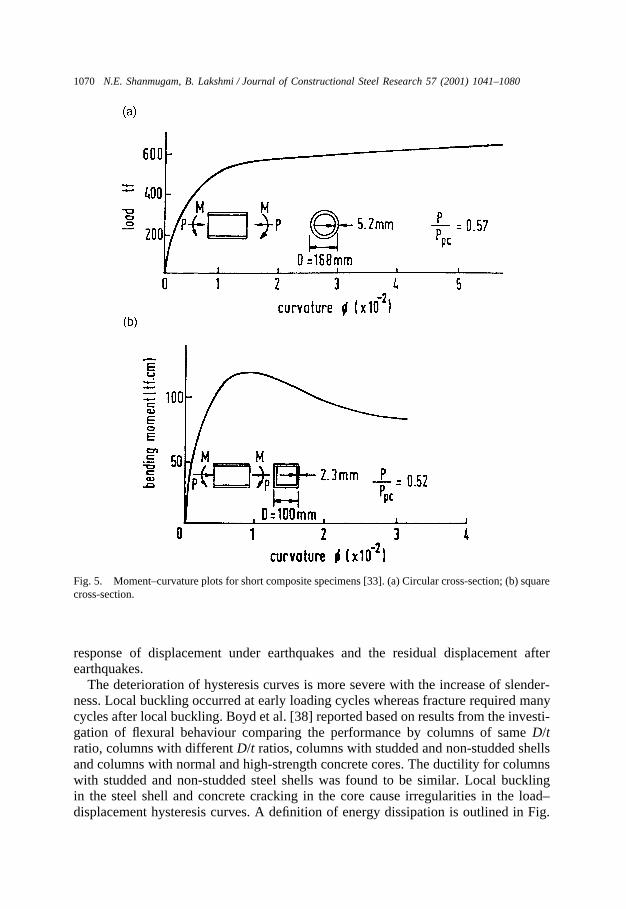
It is often necessary to determine the ductility or rotational capacity of a givencolumn. The curvature ductility, defined as the ratio of curvature at ultimate load tothe curvature at yield, can be obtained analytically by studying the moment curvaturerelationship. Kitada [33] described the difference in local buckling modes betweencross-sections of steel and composite columns, the difference in cross-sectionsbetween composite columns in bridge piers and buildings. It is observed that theductility of the composite beam-column specimen with rectangular cross-section issmall compared to that with a circular cross-section in the case of large axial com-pression (Fig. 5).
To determine the curvature ductility of composite steel concrete columns and toinvestigate on the adequacy of their use in seismic areas, a study was conducted byItani [34]. Parameters such as thickness of steel jacket, D/t ratio and the percentageof longitudinal reinforcement were considered in the analysis. To ensure full com-posite action between the steel jacket and the concrete, shear studs were providedthroughout the length of the column.
9. Seismic behaviour
Partially-encased composite steel–concrete beam-columns under cyclic andpseudo-dynamic loading was presented by Elnashai and Elghazouli [35,36]. Pro-vision of additional transverse bars intended to inhibit local buckling at large dis-placements and to increase the interaction between the two materials was consideredin the study. The modified section seemed to be showing significant improvementin the ductility and energy absorption capacity under cyclic and transient dynamicloading. After the shock of Hyogo-Ken Nambu earthquake, a method of insertingan additional steel tube into the steel bridge pier was considered by Nakanishi et al.[37]. In this method, the ductility of the bridge pier was significantly enhanced ifthe cross-section was designed such that the axial compressive load caused by deadload of the superstructure was mainly carried by the inner tube. It was found fromthe study that the natural period of vibration for bridge piers affect significantly the
1070 N.E. Shanmugam, B. Lakshmi / Journal of Constructional Steel Research 57 (2001) 1041–1080
Fig. 5. Moment–curvature plots for short composite specimens [33]. (a) Circular cross-section; (b) squarecross-section.
response of displacement under earthquakes and the residual displacement afterearthquakes.
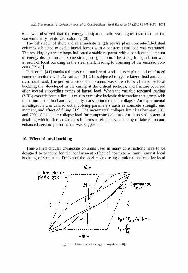
The deterioration of hysteresis curves is more severe with the increase of slender-ness. Local buckling occurred at early loading cycles whereas fracture required manycycles after local buckling. Boyd et al. [38] reported based on results from the investi-gation of flexural behaviour comparing the performance by columns of same D/tratio, columns with different D/t ratios, columns with studded and non-studded shellsand columns with normal and high-strength concrete cores. The ductility for columnswith studded and non-studded steel shells was found to be similar. Local bucklingin the steel shell and concrete cracking in the core cause irregularities in the load–displacement hysteresis curves. A definition of energy dissipation is outlined in Fig.
1071N.E. Shanmugam, B. Lakshmi / Journal of Constructional Steel Research 57 (2001) 1041–1080
6. It was observed that the energy–dissipation ratio was higher than that for theconventionally reinforced columns [38].
The behaviour of short and intermediate length square plain concrete-filled steelcolumns subjected to cyclic lateral forces with a constant axial load was examined.The resulting hysteretic loops indicated a stable response with a considerable amountof energy dissipation and some strength degradation. The strength degradation wasa result of local buckling in the steel shell, leading to crushing of the encased con-crete [39,40].
Park et al. [41] conducted tests on a number of steel-encased plain and reinforcedconcrete sections with D/t ratios of 34–214 subjected to cyclic lateral load and con-stant axial load. The performance of the columns was shown to be affected by localbuckling that developed in the casing at the critical sections, and fracture occurredafter several succeeding cycles of lateral load. When the variable repeated loading(VRL) exceeds certain limit, it causes excessive inelastic deformation that grows withrepetition of the load and eventually leads to incremental collapse. An experimentalinvestigation was carried out involving parameters such as concrete strength, endmoment, and effect of filling [42]. The incremental collapse limit lies between 70%and 79% of the static collapse load for composite columns. An improved system ofdetailing which offers advantages in terms of efficiency, economy of fabrication andenhanced seismic performance was suggested.
10. Effect of local buckling
Thin-walled circular composite columns used in many constructions have to bedesigned to account for the confinement effect of concrete restraint against localbuckling of steel tube. Design of the steel casing using a rational analysis for local
Fig. 6. Definitions of energy dissipation [38].
1072 N.E. Shanmugam, B. Lakshmi / Journal of Constructional Steel Research 57 (2001) 1041–1080
buckling would lead to considerable saving on material cost. A concrete-filled tubehas a local buckling capacity of about 50% more than that for unfilled tube sincethe steel tube is restrained against buckling inwards by the concrete infill [43]. Effectof local buckling on the axial compressive strength of circular steel tubes is a functionof the plate diameter to thickness ratio (D/t) and is accounted in a number of designstandards through the use of an effective diameter or an effective area.
A model for local buckling of steel plates when in contact with a rigid mediumwas developed by Wright [44]. His theoretical model is based on the energy methodbut is applicable to uniform compression only. A semi-analytical procedure to incor-porate the elastic and in-elastic local buckling of plates with clamped loaded edgeswere proposed using cubic polynomial [45,46]. A post local buckling model basedon the effective width principle was established [47]. The local buckling stress wasset equal to the yield stress for columns that buckled inelastically. Local bucklingstrain was determined as the point at which a significant change occurs in the averageload–strain relationship. The model seems to be very accurate in the elastic regionwith residual stresses in the order of 30%. However, the finite strip analysis doesnot incorporate initial imperfections which play a significant role in reducing thelocal-buckling load in thin-walled structures.
11. Long-term effects
The physical properties of concrete are such that it contracts while setting followedby a lengthy period of shrinkage and of creep under load. Increasing lateral strainaccompanied by transfer of stress from concrete to steel results in reduction of ulti-mate load capacity of slender columns subjected to eccentric load. In theory, shrink-age of the concrete is more effectively restrained in steel–concrete columns than inordinary reinforced concrete columns. Because of the humid conditions inside thesteel section, the coefficient of contraction is relatively low and shrinkage occursvery slowly.
A design procedure was proposed by Bradford and Gilbert [48] for estimating themaximum acceptable service load on a slender, eccentrically loaded composite col-umn. It is found that the loss of strength due to long-term effects such as creep andshrinkage is insignificant; however their effects are yet to be quantified. Due to creepunder sustained stress, concrete does not have a constant value for its modulus ofelasticity. The stiffness EI of cross-sections under initial applications of service loads(relatively low stress values) can be taken as the sum of flexural stiffnesses for allcomponent parts of the section:
EI � EsIs � EcIc (33)
The value of Ic will diminish after the concrete cracks in flexural tension, and theeffective value of Ec will be reduced from long-time loading at high levels of com-pression stress. Under sustained loading, creep of concrete results in increase in thelateral deflection of a composite column and a reduction in its strength and stiffness.Basu and Sommerville [25] gave magnification factors to be applied to that part of
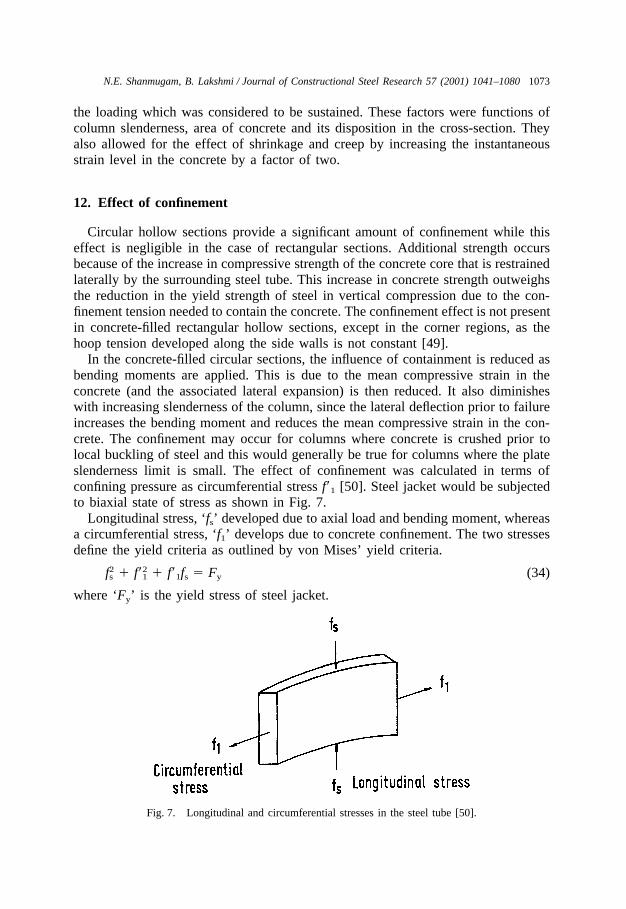
1073N.E. Shanmugam, B. Lakshmi / Journal of Constructional Steel Research 57 (2001) 1041–1080
the loading which was considered to be sustained. These factors were functions ofcolumn slenderness, area of concrete and its disposition in the cross-section. Theyalso allowed for the effect of shrinkage and creep by increasing the instantaneousstrain level in the concrete by a factor of two.
12. Effect of confinement
Circular hollow sections provide a significant amount of confinement while thiseffect is negligible in the case of rectangular sections. Additional strength occursbecause of the increase in compressive strength of the concrete core that is restrainedlaterally by the surrounding steel tube. This increase in concrete strength outweighsthe reduction in the yield strength of steel in vertical compression due to the con-finement tension needed to contain the concrete. The confinement effect is not presentin concrete-filled rectangular hollow sections, except in the corner regions, as thehoop tension developed along the side walls is not constant [49].
In the concrete-filled circular sections, the influence of containment is reduced asbending moments are applied. This is due to the mean compressive strain in theconcrete (and the associated lateral expansion) is then reduced. It also diminisheswith increasing slenderness of the column, since the lateral deflection prior to failureincreases the bending moment and reduces the mean compressive strain in the con-crete. The confinement may occur for columns where concrete is crushed prior tolocal buckling of steel and this would generally be true for columns where the plateslenderness limit is small. The effect of confinement was calculated in terms ofconfining pressure as circumferential stress f�1 [50]. Steel jacket would be subjectedto biaxial state of stress as shown in Fig. 7.
Longitudinal stress, ‘ fs’ developed due to axial load and bending moment, whereasa circumferential stress, ‘ f1’ develops due to concrete confinement. The two stressesdefine the yield criteria as outlined by von Mises’ yield criteria.
f2s � f�2
1 � f�1fs � Fy (34)
where ‘Fy’ is the yield stress of steel jacket.
Fig. 7. Longitudinal and circumferential stresses in the steel tube [50].

1074 N.E. Shanmugam, B. Lakshmi / Journal of Constructional Steel Research 57 (2001) 1041–1080
Fig. 8. Buckling modes of steel and composite sections [33]. (a) Steel cross-section; (b) composite cross-section.
13. Comparison with steel columns
The basic buckling modes of steel and composite columns are illustrated in Fig.8 [33]. In the case of concrete-filled steel tubular columns, concrete inside the tubeprevents inward-buckling modes of the steel tube wall, and the tube-wall in turnprovides effective lateral confinement to the concrete inside the tube. Typicalexamples of load–average strain curves for steel and concrete-filled column areshown in Fig. 9.
The unloading response of the tubes becomes rapid in case of composite columns,with increasing tube wall slenderness due to local buckling. The response of com-posite tube is similar to that for the bare steel tubes. The hysteretic loops in theconcrete filled columns were relatively narrow in the early cycles, and then becomewider at the later cycles due to strain hardening in the post-ultimate region. Themaximum strength is obtained at about a strain of 0.2% in the steel box columnsand in the range of 0.3–0.4% in the concrete-filled columns. Obviously, the
Fig. 9. Load–average strain curves under cyclic loading [14].

1075N.E. Shanmugam, B. Lakshmi / Journal of Constructional Steel Research 57 (2001) 1041–1080
maximum strength of concrete-filled columns was much larger than those of the steelcolumns. Therefore, it can be concluded that the concrete-filled column shows goodstructural performance through higher ductility and higher strength [14].
14. Design codes
Over the last two decades, researchers have suggested analytical methods anddesign procedures for composite columns and design codes have been formulated.Each of these codes is written so as to reflect the design philosophies and practicesin the respective countries. Over the last two decades, different specific codes forthe design of concrete filled steel tubular columns have been used.
14.1. The building code requirements of reinforced concrete (ACI 318-89)
According to ACI 318-89, a composite column is a concrete column reinforcedwith a structural steel shape or tubing in addition to reinforcing bars. In order toconsider the slenderness effects, an equivalent radius of gyration and flexural stiff-ness are used with a parameter of sustained load ratio, and hence without any sus-tained load, radius of gyration should be taken as zero. The limiting thickness ofsteel tube to prevent local buckling are based on achieving yield stress in a hollowsteel tube under monotonic axial loading which is not a necessary requirement forin-filled composite column. A parameter for the softening influence of creep in con-crete that is subjected to sustained compressive loading is included.
14.2. Load and resistance factor design method (AISC-LRFD)
This is based on the same principles as ACI code. Design is based on equationsfor steel columns. Nominal strength is estimated on the basis of ultimate resistanceto the load, and reduction factors are then applied. The nominal axial load capacityis reduced according to the slenderness ratio. Neither the ACI-318 nor the AISC-LRFD provisions explicitly consider confinement effects on strength or ductility ofmember analysed. ACI provisions for calculating the strength interaction betweenaxial and flexural effects are essentially the same as those for reinforced concretecolumn, whereas AISC-LRFD are based on the bilinear interaction formulae whichhave the same form as those of steel columns. In the above design methods, flexuralstiffness is underestimated and confining effect of the steel tube on the concrete coreis ignored. The influence of creep is ignored for concrete in composite columnsaccording to AISC-LRFD specification.
14.3. Architectural Institute of Japan (AIJ)
A composite structural system using concrete and steel shape is called ‘steelreinforced concrete’ (SRC) in Japan. The allowable stress design is primarilyemployed, in which working stresses are calculated based on the elastic stiffness of

1076 N.E. Shanmugam, B. Lakshmi / Journal of Constructional Steel Research 57 (2001) 1041–1080
members and allowable strength by the superposed strength formulae. Cross sectionstrength is calculated by superimposing the strength of both the steel and concretesections, thereby neglecting the interaction between steel and concrete and the effectof confinement. Euler buckling load is used with a reduced concrete stiffness andfactors of safety for both concrete and steel. The method is applicable to asymmetri-cal sections and columns under biaxial bending.
14.4. British Standard BS 5400—Part 5
Code provisions in BS 5400 are based on limit state design with loading factorsand material safety factors. The ultimate moment is calculated from plastic stressdistribution over the cross-section, and an approximation for the interaction curvefor axial load and moment is used. Reduced concrete properties are used to accountfor the effects of creep and the use of uncracked concrete section in stiffness calcu-lation. This method is applicable to symmetrical sections only and restricted to therange of sections catered for in the European buckling curves. It underestimates thecapacity of in-filled composite columns with high-strength concrete.
14.5. European Code EC4
EC4 covers concrete encased and partially encased steel sections and concretefilled sections with or without reinforcement. This code uses limit state concepts toachieve the aims of serviceability and safety by applying partial safety factor to loadsand material properties. Based on experimental results, it was recommended that theregulations of EC4 concerning the factor of 0.85 should not be applied to hollowsections filled with high strength concrete [23]. This is the only code that treats theeffect of long-term loading separately.
All codes assume full interaction, but some impose restrictions on the shear stressat the steel–concrete interface. It is customary to use direct bearing or provide shearconnectors, if used where the specified limiting shear stress is exceeded.
15. Conclusions
Considerable progress has been made during the last two decades in the investi-gation of steel–concrete composite columns, and information available is summarizedin this paper. The details of experimental works available are given in Table 1 forencased composite columns and in Table 2 for in-filled composite columns. Thetables provide information such as number of tests, section shape, loading type, vari-ables considered in the study and the origin of work, etc. Fundamental knowledgeon composite construction system such as ultimate strength, has already beenobtained by the research carried out so far. Intensive research is required on theinteraction between steel and concrete, the effect of concrete restraining local buck-ling of steel plate elements, effect of steel section, confining concrete, etc.

1077N.E. Shanmugam, B. Lakshmi / Journal of Constructional Steel Research 57 (2001) 1041–1080
References
[1] Furlong RW. Strength of steel encased concrete beam-columns. Journal of the Structural Division,Proc. American Society of Civil Engineers 1967;93(ST5):115–30.
[2] Neogi PK, Sen HK, Chapman JC. Concrete-filled tubular steel columns under eccentric loading.The Structural Engineer 1969;47(5):187–95.
[3] Uy B, Patil SB. Concrete-filled high strength steel box columns for tall buildings: behaviour anddesign. The Structural Design of Tall Buildings 1996;5:75–93.
[4] Burr WH. Composite columns of concrete and steel. Proc. Institution of Civil Engineers1912;188:114–26.
[5] Mirza SA, Skrabek BW. Reliability of short composite beam-column strength interaction. Journalof Structural Engineering, ASCE 1991;117(8):2320–39.
[6] Mirza SA, Skrabek BW. Statistical analysis of slender composite beam-column strength. Journal ofStructural Engineering, ASCE 1992;118(5):1312–31.
[7] Hunaiti YM, Fattah BA. Design considerations of partially encased composite column. Proc. Insti-tution of Civil Engineers, Structures & Buildings 1994;106(Feb.):75–82.
[8] Ghosh RS. Strengthening of slender hollow steel columns by filling with concrete. Canadian Journalof Civil Engineering 1977;4(2):127–33.
[9] Prion HGL, Boehme J. Beam-column behaviour of steel tubes filled with high-strength concrete.In: Fourth International Colloquium, SSRC, New York, 1989:439–49.
[10] Shakir-Khalil H, Zeghiche J. Experimental behaviour of concrete-filled rolled rectangular hollow-section columns. The Structural Engineer 1989;67(19):346–53.
[11] Shakir-Khalil H, Mouli M. Further tests on concrete-filled rectangular hollow section columns. TheStructural Engineer 1990;68(20):405–13.
[12] Shakir-Khalil H, Al-Rawdan A. In: Buckner D, Shahrooz BM, editors. Composite construction insteel and concrete 3, New York: ASCE; 1994:222–35.
[13] Morino S, Matsui C, Watnabe H. Strength of biaxially loaded SRC column. In: Roeder CW, editor.Composite and mixed construction, New York: ASCE; 1984:185–94.
[14] Ge H, Usami T. Strength of concrete-filled thin walled steel box columns: experiment. Journal ofStructural Engineering, ASCE 1992;118(11):3036–54.
[15] Furlong RW. Design of steel-encased concrete beam-columns. Journal of Structural Division, ASCE1968;94(1):267–81.
[16] Rangan BV, Joyce M. Strength of eccentrically loaded slender steel tubular columns filled with highstrength concrete. ACI Structural Journal 1992;89(6):676–81.
[17] O’Brien AD, Rangan BV. Tests on slender tubular steel columns filled with high-strength concrete.Australian Civil Engineering Transactions 1993;35(4):287–92.
[18] O’Shea MD, Bridge RQ. Circular thin walled concrete filled steel tubes. In: PSSC ’95 4th PacificStructural Steel Conference, vol. 3, Steel–Concrete Composite Structures, 1995:53–60.
[19] Munoz PR, Thomas Hsu CT. Behaviour of biaxially loaded concrete-encased composite columns.Journal of Structural Engineering 1997;123(9):1163–71.
[20] Munoz PR, Thomas Hsu CT. Biaxially loaded concrete-encased composite columns: Design equ-ation. Journal of Structural Engineering, ASCE 1997;123(12):1576–85.
[21] Virdi KS, Dowling PJ. The ultimate strength of composite columns in biaxial bending. Proc. Insti-tution of Civil Engineers, Part 2 1973;55(Mar.):251–72.
[22] Task Group 20, SSRC. A specification for the design of steel–concrete composite columns. Engineer-ing Journal AISC 1979:101–45.
[23] Roik K, Bergmann R. Design method for composite columns with unsymmetrical cross-sections.Journal of Constructional Steel Research 1990;33:153–72.
[24] Stevens RF. Encased stanchions. Structural Engineers London 1965;43(2).[25] Basu AK, Sommerville W. Derivation of formulae for the design of rectangular composite columns.
Proc. Institution of Civil Engineers 1969;Suppl:233–80.[26] Roberts EH, Yam LCP. Some recent methods for the design of steel, reinforced concrete and com-
posite steel–concrete columm in UK. ACI Journal 1983;Mar–Apr:139–49.

1078 N.E. Shanmugam, B. Lakshmi / Journal of Constructional Steel Research 57 (2001) 1041–1080
[27] Bradford MA. Design strength of slender concrete-filled rectangular steel tubes. ACI Structural Jour-nal 1996;93(2):229–35.
[28] Ge H, Usami T. Strength analysis of concrete filled thin walled steel box columns. Journal of Con-structional Steel Research 1994;37:607–12.
[29] Wang YC, Moore DB. A design method for concrete-filled hollow section composite columns. TheStructured Engineer 1997;75(21):368–72.
[30] Knowles RB, Park R. Strength of concrete filled steel tubular columns. Journal of the StructuralDivision, ASCE 1969;105(12):2565–87.
[31] Ben Kato. Column curves of steel–concrete composite members. Journal of Constructional SteelResearch 1996;39(2):121–35.
[32] Suzuki H, Kato B. Shear strength of concrete filled box elements. In: Proc. Conference on joints instructural steelwork, Middlesborough, 1981.
[33] Kitada T. Ultimate strength and ductility of state of art on concrete-filled steel bridges piers in Japan.Engineering Structures 1998;20(4–6):347–54.
[34] Itani AM. Future use of composite steel–concrete columns in highway bridges. Engineering Journal,AISC 1996;3rd quarter:110–5.
[35] Elnashai AS, Elghazouli Y. Performance of composite steel–concrete members under earthquakeloading, part 1: analytical model. Earthquake Engineering and Structural Dynamics 1993;22:315–46.
[36] Elnashai AS, Elghazouli Y. Performance of composite steel–concrete members under earthquakeloading, part 2: parametric studies and design considerations. Earthquake Engineering and StructuralDynamics 1993;22:347–68.
[37] Nakanishi K, Kitada T, Nakai H. Experimental study on ultimate strength and ductility of concretefilled steel columns under strong earthquake. Journal of Constructional Steel Research1999;51:297–319.
[38] Boyd PF, Cofer WF, McLean DI. Seismic performance of steel-encased composite columns underflexural loading. ACI Structural Journal 1995;92(3):335–64.
[39] Sakino K, Tomii M. Hysteretic behaviour of concrete filled square shell tubular beam-columns failedin flexure. Transactions, Japan Concrete Institute (Tokyo) 1981;3:439–46.
[40] Sakino K, Ishibashi H. Experimental studies on concrete filled square steel tubular short columnssubjected to cyclic shearing force and constant axial force. Transactions, Architectural Institute ofJapan (Tokyo) 1985;353(July):81–9.
[41] Park RJT, Priestley MJN, Walpole WR. Reinforced concrete bridge piles. Bulletin of the New Zea-land National Society for Earthquake Engineering 1983;16(2) June.
[42] Elnashai AS, Broderick BM. Seismic resistance of composite beam-columns in multi-storey struc-tures, part 1: experimental studies. Earthquake Engineering and Structural Dynamics1993;22:201–55.
[43] Matsui C. Local buckling of concrete filled steel square tubular columns. In: Symposium papers,International Association for Bridge and Structural Engineering Conference, Luxembourg,1993:269–76.
[44] Wright HD. Buckling of plates in contact with a rigid medium. The Structural Engineer1993;71(12):209–15.
[45] Uy B, Bradford MA. Local buckling of concrete-filled high strength steel box columns for tallbuildings: behaviour and design. The Structural Design of Tall Buildings 1994;3:75–93.
[46] Cheung YK. Finite strip method in structural analysis. Oxford: Pergamon Press, 1976.[47] Uy B. Local and post-local buckling of concrete-filled steel welded box columns. Journal of Con-
structional Steel Research 1998;47:47–72.[48] Bradford MA, Gilbert RI. Time-dependent analysis and design of composite columns. Journal of
Structural Engineering 1990;116(12):3338–57.[49] Matsui C, Tsuda K, Ishibashi Y. Slender concrete filled steel tubular columns under combined com-
pression and bending. In: PSSC’95 4th Pacific Structural Steel Conference, vol. 3, Steel–ConcreteComposite Structures, 1995:29–36.
[50] Brauns J. Analysis of stress state in concrete-filled steel column. Journal of Constructional SteelResearch 1999;49:189–96.
1079N.E. Shanmugam, B. Lakshmi / Journal of Constructional Steel Research 57 (2001) 1041–1080
[51] Anslijn R, Janss J. Le calcul de charges ultimes des colonnes metalliques enrobes de beton. C.R.I.F.,Report MT 89, Apr., Brussels, 1974.
[52] Roderick JW, Loke YO. Pin-ended composite columns bent about the minor axis. Civil EngineeringTransactions 1975;17(2):51–8.
[53] Johnston BG. Guide to the stability design criteria for metal structures. 3rd ed. New York: SSRC,1976.
[54] Matsui C. Study on elasto-plastic behaviour of concrete-encased columns subjected to eccentric axialthrust, Annual Assembly of Architectural Institute of Japan, September, 1979:1627–8.
[55] Roik K, Schwalbenhofer K. Experimental and theoretical examinations on the plastic behaviour andthe rotation capacity of composite beam-columns. Berlin: Wilhelm Ernst & Sohn Verlag fur Archite-kur und technische Wissenschafen, 1989.
[56] Roik K, Bergmann R. Composite columns—design and examples for construction. State of the artreport on composite or mixed steel–concrete construction for buildings. In: 2nd US–Japan Seminaron Composite and Mixed Construction, Seattle, Washington, New York: ASCE; 1984. pp. 272–4.
[57] Elnashai AS, Takanashi K, Elghazouli AY, Dowling PJ. Experimental behaviour of partially encasedcomposite beam-columns under cyclic and dynamic loads. Part 2. Proc. Institution of Civil Engineers,Structures & Buildings 1991;91(June):259–72.
[58] Nakamura T. Experimental study on compression strength of concrete-filled square tubular steelcolumns. Journal of Structural Engineering, ASCE 1994;40:411–7.
[59] Wium JA, Lebet JP. Simplified calculation method for force transfer. Journal of Structural Engineer-ing: ASCE 1994;120(3):728–45.
[60] Ricles JM, Paboojian SD. Seismic performance of steel-encased composite columns. Journal ofStructural Engineering, ASCE 1994;120(8):2474–94.
[61] Mirza SA, Hyttinen V, Hyttinen E. Physical tests and analyses of composite steel–concrete beam-columns. Journal of Structural Engineering, ASCE 1996;122(11):1317–26.
[62] Wang YC. Tests on slender composite columns. Journal of Constructional Steel Research1999;48:25–41.
[63] Drysdale RG, Huggins MW. Sustained biaxial load on slender concrete columns. Journal of Struc-tural Engineering, ASCE 1971;97(5):1423–42.
[64] Bridge RQ. Concrete-filled steel tubular columns. Civil Engineering Transactions, Institution ofEngineers, Australia 1976;CE18:127–33.
[65] Sasaki R. Experimental study on buckling strength of composite columns having steel tube. AnnualAssembly of Architectural Institute of Japan, October 1984:2735–6.
[66] Konno K, Kei T, Nagashima T. Behaviour of Concrete-filled square steel columns. InternationalAssociation for Bridge and Structural Engineering Conference, Brussels, 1990:269–70.
[67] Cai SH. Influence of moment distribution diagram on load-carrying capacity of concrete-filled steeltubular columns. In: Proc. Third International Conference on Steel–Concrete Composite Structures,ASCCS, Fukuoka (Japan) September 1991:113-18.
[68] CFT Working Group. Compression test on concrete-filled circular steel tube columns. Kozai Club,December 1993.
[69] Fuji K. Structural and ultimate behaviour of two types of mortar filled steel tubes in compression.Proc. In: Fourth International Conference on Steel–Concrete Composite Structures, ASCCS, Kosice,Slovakia, June 1994:194–7.
[70] Kilpatrick AE. Response of composite columns to applied axial shortening. In: Proc. Fourth Inter-national Conference on Steel–Concrete Composite Structures, ASCCS, Kosice, Slovakia, June1994:218–21.
[71] Hayashi N, Fukumoto T, Inoue T, Akiyama H, Okada T. Shear-flexural behavior of concrete-filledsquare steel tubular columns using high-strength materials. In: PSSC’95 Fourth Pacific StructuralSteel Conference, vol. 3, Steel–Concrete Composite Structures, 1995:13–20.
[72] Kim WJ, Park JM, Oh YS. The properties of mechanical behaviour of concrete filled steel tubecolumn. In: PSSC’95 Fourth Pacific Structural Steel Conference, vol. 3, Steel–Concrete CompositeStructures, 1995:21–8.
[73] Bridge RQ, O’Shea MD, Gardner P, Grigson R, Tyrell J. Local buckling of square thin-walled steel

1080 N.E. Shanmugam, B. Lakshmi / Journal of Constructional Steel Research 57 (2001) 1041–1080
tubes with concrete in-fill. In: Proc. International Conference on Structural Stability and Design,Sydney, 1995:307–14.
[74] Kilpatrick AE. The behaviour of high-strength composite concrete columns. PhD Thesis, CurtinUniversity of Technology, Australia, 1996.
[75] Uy B, Das S. Behaviour and design of concrete filled fabricated steel box columns. In: Proceedingsof 15th Australasian conference on the mechanics of structures and materials, Melbourne (Australia),December, 1997. pp. 129–34.
[76] Thirugnanasundralingam K, Thayalan P, Patnaikuni I. Behaviour of concrete filled steel tubularcolumns subjected to repeated loading. In: Proceedings of the 15th Australasian conference on themechanics of structures and materials, Melbourne (Australia), December, 1997. pp. 165–72.
[77] Kawano A, Matsui C. Composite construction in steel and concrete III. In: Dale Buckner C, ShahroozBM, editors. Proceedings of an Engineering Foundation conference, Swabian Conference Center,Irsee, Germany, June 9–14. New York: ASCE; 1997. pp. 602–15.
Related Documents