State-of-the-art of solar thermal power plants—A review V. Siva Reddy a,n , S.C. Kaushik b , K.R. Ranjan b , S.K. Tyagi c a Sardar Patel Renewable Energy Research Institute, Vallabh Vidhyanagar 388120, Gujarat, India b Centre for Energy Studies, Indian Institute of Technology Delhi, Hauz Khas 110016, New Delhi, India c Sardar Swaran Singh National Institute of Renewable Energy, Jalandhar–Kapurthala Road, Wadala Kalan, Kapurthala 144601, Punjab, India article info Article history: Received 18 November 2012 Received in revised form 19 June 2013 Accepted 24 June 2013 Keywords: Parabolic trough concentrator Parabolic dish concentrator Central tower receiver Solar thermal power plant Techno-economic analysis abstract The solar thermal power plant is one of the promising renewable energy options to substitute the increasing demand of conventional energy. The cost per kW of solar power is higher and the overall efficiency of the system is lower. In the present communication, a comprehensive literature review on the scenario of solar thermal power plants and its up-to-date technologies all over the world is presented. Results of the technical and economical feasibility studies by researchers are reported in brief for further reference. It is observed that the solar thermal power plants have come out of the experimental stage to commercial applications. Case studies of typical 50 MW solar thermal power plants in the Indian climatic conditions at locations such as Jodhpur and Delhi is highlighted with the help of techno-economic model. Different solar concentrator technologies (parabolic trough, parabolic dish and central power tower) for solar thermal power plants are compared economically. It has been found that the parabolic dish concentrating solar Stirling engine power plant generate electricity at a lower unit cost than the other two solar technologies considering 30 years lifespan and 10% interest rate on investment. & 2013 Elsevier Ltd. All rights reserved. Contents 1. Introduction ........................................................................................................ 258 2. Status of low and medium temperature technologies of solar thermal power plants .............................................. 259 3. Status of high temperature technologies of solar thermal power plants ........................................................ 261 4. Economic assessment of low, medium and high temperature solar thermal power plants for Indian tropical climates—case studies ........ 266 4.1. Techno-economic analysis of PTCSTPP ............................................................................. 267 4.2. Techno-economic analysis of PDCSSPP ............................................................................. 267 4.3. Techno-economic analysis of CTRSTPP ............................................................................. 268 5. Conclusions ........................................................................................................ 269 References ............................................................................................................. 271 1. Introduction The ever increasing demand of energy for development of the society is fulfilled by a variety of energy sources. Large scale energy utilization has led to a better quality of life and faster all round development; it has also generated many critical problems [1]. The most prominent of these is the harmful effect on the environment in various forms leading to global warming and climate change [2]. At the same time, the fossil fuel resources are also fast depleting due to over exploitation. Therefore, it is worth to explore the alternative energy sources, systems and technologies for sustain- able development, if not fully but at least to substitute an appreciable amount of conventional energy to mitigate the harm- ful effect to some extent. Other than fossil fuels, nuclear and large hydro-power, there are a number of sources of energy which have started contribution in a small way to the world's present energy demand and supply scenarios. These include energy sources like wind energy, small hydro, photovoltaic conversion, bio-mass, tidal, geothermal energy and solar thermal power plants. Among the renewable energy Contents lists available at SciVerse ScienceDirect journal homepage: www.elsevier.com/locate/rser Renewable and Sustainable Energy Reviews 1364-0321/$ - see front matter & 2013 Elsevier Ltd. All rights reserved. http://dx.doi.org/10.1016/j.rser.2013.06.037 n Corresponding author. Mobile: +91 9898 722 118; fax: +91 2692 237 982. E-mail address: [email protected] (V. Siva Reddy). Renewable and Sustainable Energy Reviews 27 (2013) 258–273

State-of-the-art of solar thermal power plants—A review
Nov 28, 2015
review solar thermal power plants
Welcome message from author
This document is posted to help you gain knowledge. Please leave a comment to let me know what you think about it! Share it to your friends and learn new things together.
Transcript

Renewable and Sustainable Energy Reviews 27 (2013) 258–273
Contents lists available at SciVerse ScienceDirect
Renewable and Sustainable Energy Reviews
1364-03http://d
n CorrE-m
journal homepage: www.elsevier.com/locate/rser
State-of-the-art of solar thermal power plants—A review
V. Siva Reddy a,n, S.C. Kaushik b, K.R. Ranjan b, S.K. Tyagi c
a Sardar Patel Renewable Energy Research Institute, Vallabh Vidhyanagar 388120, Gujarat, Indiab Centre for Energy Studies, Indian Institute of Technology Delhi, Hauz Khas 110016, New Delhi, Indiac Sardar Swaran Singh National Institute of Renewable Energy, Jalandhar–Kapurthala Road, Wadala Kalan, Kapurthala 144601, Punjab, India
a r t i c l e i n f o
Article history:Received 18 November 2012Received in revised form19 June 2013Accepted 24 June 2013
Keywords:Parabolic trough concentratorParabolic dish concentratorCentral tower receiverSolar thermal power plantTechno-economic analysis
21/$ - see front matter & 2013 Elsevier Ltd. Ax.doi.org/10.1016/j.rser.2013.06.037
esponding author. Mobile: +91 9898 722 118ail address: [email protected] (V. Siva Re
a b s t r a c t
The solar thermal power plant is one of the promising renewable energy options to substitute theincreasing demand of conventional energy. The cost per kW of solar power is higher and the overallefficiency of the system is lower. In the present communication, a comprehensive literature review onthe scenario of solar thermal power plants and its up-to-date technologies all over the world ispresented. Results of the technical and economical feasibility studies by researchers are reported in brieffor further reference. It is observed that the solar thermal power plants have come out of theexperimental stage to commercial applications. Case studies of typical 50 MW solar thermal powerplants in the Indian climatic conditions at locations such as Jodhpur and Delhi is highlighted with thehelp of techno-economic model. Different solar concentrator technologies (parabolic trough, parabolicdish and central power tower) for solar thermal power plants are compared economically. It has beenfound that the parabolic dish concentrating solar Stirling engine power plant generate electricity at alower unit cost than the other two solar technologies considering 30 years lifespan and 10% interest rateon investment.
& 2013 Elsevier Ltd. All rights reserved.
Contents
1. Introduction . . . . . . . . . . . . . . . . . . . . . . . . . . . . . . . . . . . . . . . . . . . . . . . . . . . . . . . . . . . . . . . . . . . . . . . . . . . . . . . . . . . . . . . . . . . . . . . . . . . . . . . . 2582. Status of low and medium temperature technologies of solar thermal power plants . . . . . . . . . . . . . . . . . . . . . . . . . . . . . . . . . . . . . . . . . . . . . . 2593. Status of high temperature technologies of solar thermal power plants . . . . . . . . . . . . . . . . . . . . . . . . . . . . . . . . . . . . . . . . . . . . . . . . . . . . . . . . 2614. Economic assessment of low, medium and high temperature solar thermal power plants for Indian tropical climates—case studies . . . . . . . . 266
4.1. Techno-economic analysis of PTCSTPP . . . . . . . . . . . . . . . . . . . . . . . . . . . . . . . . . . . . . . . . . . . . . . . . . . . . . . . . . . . . . . . . . . . . . . . . . . . . . 2674.2. Techno-economic analysis of PDCSSPP . . . . . . . . . . . . . . . . . . . . . . . . . . . . . . . . . . . . . . . . . . . . . . . . . . . . . . . . . . . . . . . . . . . . . . . . . . . . . 2674.3. Techno-economic analysis of CTRSTPP . . . . . . . . . . . . . . . . . . . . . . . . . . . . . . . . . . . . . . . . . . . . . . . . . . . . . . . . . . . . . . . . . . . . . . . . . . . . . 268
5. Conclusions . . . . . . . . . . . . . . . . . . . . . . . . . . . . . . . . . . . . . . . . . . . . . . . . . . . . . . . . . . . . . . . . . . . . . . . . . . . . . . . . . . . . . . . . . . . . . . . . . . . . . . . . 269References . . . . . . . . . . . . . . . . . . . . . . . . . . . . . . . . . . . . . . . . . . . . . . . . . . . . . . . . . . . . . . . . . . . . . . . . . . . . . . . . . . . . . . . . . . . . . . . . . . . . . . . . . . . . . 271
1. Introduction
The ever increasing demand of energy for development of thesociety is fulfilled by a variety of energy sources. Large scale energyutilization has led to a better quality of life and faster all rounddevelopment; it has also generated many critical problems [1]. Themost prominent of these is the harmful effect on the environmentin various forms leading to global warming and climate change [2].
ll rights reserved.
; fax: +91 2692 237 982.ddy).
At the same time, the fossil fuel resources are also fast depletingdue to over exploitation. Therefore, it is worth to explore thealternative energy sources, systems and technologies for sustain-able development, if not fully but at least to substitute anappreciable amount of conventional energy to mitigate the harm-ful effect to some extent.
Other than fossil fuels, nuclear and large hydro-power, thereare a number of sources of energy which have started contributionin a small way to the world's present energy demand and supplyscenarios. These include energy sources like wind energy, smallhydro, photovoltaic conversion, bio-mass, tidal, geothermal energyand solar thermal power plants. Among the renewable energy

Brayton Cycle
Solar Power Generation
Solar Photovoltaic Solar Thermal
Coal Fired Thermal Plant
Gas Fired Combined Cycle Power Plant
Solar Aided Solar Alone
Linear Fresnel Reflector Solar Thermal Power
plant
Parabolic Dish Concentrating Solar
Power plant
Central Tower Receiver Solar Thermal Power Plant
Stirling Cycle Rankine Cycle Rankine Cycle Rankine Cycle
Parabolic Trough Concentrating Solar Thermal Power plant
Fig. 1. Schematic view of solar power generation methods.
V. Siva Reddy et al. / Renewable and Sustainable Energy Reviews 27 (2013) 258–273 259
sources, solar power generation undoubtedly offers the mostpromising and viable option for electricity generation for thepresent and future. The schematic views of solar power generationmethods are shown in Fig. 1.
In the present study, the authors have focused on the solarthermal conversion route of power generation only. The basicmechanism of conversion and utilization of solar energy for solarthermal power generation is available in the literature elsewhere.The main differences are found to be in the solar energy collectiondevices, working fluids, solar thermal energy storage and heat-exchanger, and suitable solar thermal power cycles. Solar thermalpower cycles are classified as low (up to 1001 C), medium (up to4001 C) and high (above 4001 C) temperature cycles [1].
2. Status of low and medium temperature technologiesof solar thermal power plants
Low temperature solar thermal power plants use flat-platecollectors, or solar ponds for collection of solar energy. Theworking fluid of low boiling points; organic fluids like methylchloride and toluene, and refrigerants like R-11, R-113 and R-114are normally used in the Rankine cycle. Solar power plants of thistype having generation capacities up to about 50 kW wereinstalled in many parts of the world, particularly Africa, in 1970s.The reported Rankine cycle efficiency of 7–8% and efficiency of thesolar flat-plate collector system of about 25% lead to an overallefficiency of only 2%. The cost of similar solar thermal power plantof 10 kW installed at IIT Chennai in 1979–1980 were estimatedabout Rs. 300,000 per kW for 6–8 h of daily operation. In order toreduce the cost, solar ponds have been used instead of flat-platecollectors in Israel for 6 kW and 150 kW capacities. Systemsworking on the solar chimney concept have also been tried inManzanares, Spain as an experimental pilot plant [1].
Medium temperature solar power plants use the line focusingparabolic solar collector at a temperature about 4001 C. Significantadvances have been made in parabolic collector technology as wellas organic Rankine cycle technology to improve the performanceof parabolic trough concentrating solar thermal power plant(PTCSTPP). A parabolic trough collector consists of long parallelrows of reflectors made by bending a sheet of reflective material(silvered low-iron float glass) into a parabolic shape [3]. At the
focal point of the reflector is the absorber tube or receiver. Thereceiver is a black treated metal tube, covered with a glass tube,the space between the pipe and glass cover is evacuated to reduceheat losses. The rows are arranged along a north–south axis andthey can rotate from east to west over each day. Parabolic troughscan achieve concentration ratios (ratio of solar flux on the receiverto that on the mirrors) of between 10 and 100. A heat transfer fluid(HTF) is circulated through the receiver absorber tube to removethe solar heat. The HTF can be heated to temperatures of up to673 K. The fluid is pumped to a heat exchanger where its heat istransferred to water or steam.
A tracking mechanism is to be used to follow the sun and mustbe able to track the sun during periods of intermittent cloud cover.Finally, then return the parabolic trough concentrator to itsoriginal position at the end of the day or during the night. Atpresent tracking system for the parabolic trough concentrator isbased on “virtual” tracking. The traditional sun-tracking unit withsensors that detect the position of the sun has been replaced by asystem based on calculation of the sun position using a mathe-matical algorithm [4]. The biggest application of this type ofsystem is the southern California power plants known as SolarElectric Generating Systems (SEGS), which have a total installedcapacity of 354 MWe [5]. SEGS-I of 14 MWe capacity was set up in1984. SEGS-II to VII was of 30 MWe each, and SEGS-VIII and IX areof 80 MWe each. The collector array for SEGS-IX has an area of483,960 m2. SEGS-VIII which started operation in 1990 is reportedto have cost $4000 per kW.
A recent development in cost effective concentrators is thedesign of the Euro Trough, a new parabolic trough concentrator, inwhich an advanced lightweight structure is used to achieve cost-efficient solar power generation [6,7]. More details on this devel-opment of parabolic concentrator system are given in Table 1.
The parabolic trough solar power plant can collect up to60–70% of the incident solar radiation and has achieved a peakelectrical conversion efficiency of 20–25% (net electricity genera-tion to incident solar radiation). A number of researchers havecarried out works on the solar parabolic trough concentrator basedsolar power system with varied perspectives. Some of the findingsare presented in this paper for further reference in the researchworks with the aim to improve the performance of the solarthermal power generation systems. Treadwell et al. [8] presentedthe performance of single-axis tracking parabolic trough solar

Table 1Data on one-axis parabolic trough concentrators [3].
Collector Structure Aperturewidth (m)
Focallength(m)
Length perelement(m2)
Length percollector(m)
Mirror areaper drive(m2)
Receiverdiameter(m)
Geometricconcentration(SU)
Mirror type Drive Peak opticalefficiency(%)
LS-1 Torque tube 2.55 0.94 6.3 50.2 128 0.04 61:1 Silvered low-iron float glass
Gear 71
LS-2 Torque tube 5 1.49 8 49 235 0.07 71:1 Silvered low-iron float glass
Gear 76
LS-3 V-trussframework
5.76 1.1 12 99 545 0.07 82:1 Silvered low-iron float glass
Hydraulic 80
New IST Space frame 2.3 0.76 6.1 49 424 0.04 50:1 Silvered thinglass
Jack screw 78
Eurotrough
Square trusstorque box
5.76 1.71 12 150 817 0.07 82:1 Silvered low-iron float glass
Hydraulic 80
Dukesolar
Aluminumspace frame
5 1.49 8 49–65 235–313 0.07 71:1 Silvered low-iron float glass
Hydraulicor gear
80
V. Siva Reddy et al. / Renewable and Sustainable Energy Reviews 27 (2013) 258–273260
collectors based on the typical meteorological year input data of11 sites. North–south horizontal axis parabolic trough collectorperformance superiority has been recommended based on theirresults. Treadwell and Grandjean [9] discussed the certain sys-tematic errors in the angle between the reflector vertex-focus axisand the vertex-sun axis and systematic receiver location error inthe vectorial deviation of a receiver from focus on performanceand, therefore, their influence on the design of troughs. Guven andBannerot [10] presented the mathematical derivation of concen-tration ratio and rim angle in parabolic troughs. Guven et al. [11]presented a rational approach for multi-objective design andoptimization of parabolic trough solar collectors for differentdesign environments. Odeh and Morrison [12] developed a tran-sient simulation model for analysis of the performance of indus-trial water heating systems using parabolic trough solar collectors.Tao et al. [13] presented the operational principle and designmethod of a new trough solar concentrator. The influence ofimportant design and characteristic parameters are analyzed andoptimized in the paper.
Mullick and Nanda [14] presented a different approach toevaluate the heat loss factor of a tubular absorber with aconcentric glass cover. Kearney et al. [15] carried out the feasibilityof utilizing a molten salt as the heat transfer fluid and for thermalstorage in a parabolic trough solar field to improve systemperformance. Bakos et al. [16] developed a simulation program,based upon the variation of collector's efficiency as a function ofheat transfer fluid flux, pipe diameter, solar radiation intensity andactive area of the parabolic trough concentrator. Naeeni andYaghoubi [17] presented a study on heat transfer from a receivertube of the parabolic trough collector of the 250 kW solar powerplants in Shiraz (Iran). The effects of variation of collector anglebased on wind velocity are studied here.
You and Hu et al. [18] studied feasibility of the reheat-regenerative Rankine power cycle for the parabolic trough collec-tor. They also investigated the optimal thermal and exergeticefficiencies for the collector and power cycle. Gang et al. [19]designed a low temperature solar thermal electric generation withand without regenerative heat exchanger in organic Rankine cycle(ORC). It has been found that the ORC with regenerative heatexchanger has the efficiency of about 8.6% which is relativelyhigher by 4.9% than that without the regenerative heat exchanger.Fernandez-Garcia et al. [20] presented a survey of concentratingsolar system especially for the steam power cycles for electricitygeneration.
Kerkeni et al. [21] presented a close analysis and evaluation ofthe long-term performance of the system. Lechon et al. [22]discussed the opportunities to improve the performance of50 MW solar parabolic trough thermal plants in Spain, by the life
cycle assessment in order to reduce their environmental impacts.Montes et al. [23] described the influence of the solar multiple onthe annual performance of parabolic trough solar thermal powerplants with direct steam generation. Munoz et al. [24] proposed aconceptual design of a solar boiler and found that overall efficiencyof the conversion of direct solar irradiation energy to electricity isabove 20%. Mohammed et al. [25] proposed and analyzed aprototype of a 50 MW concentrated solar power plant (CSPP)based on the solar irradiation data for electricity generation inJordan. It was found that Jordan has an outstanding potential forCSPP, especially in the southern locations of the country. Birnbaumet al. [26] have done comparative analysis of direct steam genera-tion parabolic trough power plants with and without thermalstorage facility. They found that depending on the live steamparameters, a reheat is necessary within the power block. Yanet al. [27] presented a dynamic model of solar parabolic troughcollectors using explicit Euler's method. Different working condi-tions of the collector structure and thermal parameters have beenconsidered in this model. The simulated results are validated usingthe selected real test data on typical summer and winter days.Garcia et al. [28] described a simulation model that predictedthe performance of parabolic trough solar thermal power plantswith a thermal storage system. Results based on this model of a50 MW power plant are presented and compared to the realperformance data.
Montes et al. [29] analyzed the contribution of solar thermalpower to improve the performance of gas-fired combined cycles.An integrated solar combined cycle power plant was proposedwhich consists of a parabolic trough field coupled to the bottom-ing steam cycle of a combined cycle gas turbine power plant.Garcia-Barberena et al. [30] developed SimulCET computer pro-gram for analysis of the influence of different operational strate-gies on the performance of parabolic trough solar power plants.The results generated by SimulCET were validated with currentexperimental data. Feldhoff et al. [31] described and compared thetwo types of plants (direct steam generated system with andwithout thermal energy storage) based on their design & perfor-mance. The results indicated further effort in the development of acommercial storage system for direct steam generated solar powerplants. Bonilla et al. [32] developed a dynamic simulation fordesign and development of a direct steam generation parabolictrough solar thermal power plant. The dynamic simulation is notonly the equation-based object-oriented model but also includesfeatures to facilitate the simulation process.
Kreider [33] explained entropy level of the solar resource asconverted to heat in various types of solar collectors. Singh andKaushik [34] analyzed solar thermal power system using finite-time thermodynamics in order to find the optimum operating

V. Siva Reddy et al. / Renewable and Sustainable Energy Reviews 27 (2013) 258–273 261
temperature. Singh et al. [35] performed energy analysis based onexergy concept of second law of thermodynamics for a solarthermal power system. Basic energy and exergy analysis for thesystem components (viz parabolic trough collector/receiver andRankine heat engine, etc.) are carried out for evaluation of therespective losses as well as exergetic efficiency for typical solarthermal power systems under given operating conditions.
Gupta and Kaushik [36] analyzed the possibilities of furtherimprovement in efficiency of the solar thermal power plant (STPP)and evaluated the optimum bleed pressure and mass fraction ofbleed steam for the enhancement of the efficiency of the solarthermal power plant. Montes et al. [37] described a thermo fluiddynamic model for parabolic trough collectors. Based on this modelthey analyzed the influence of factors (heat loss and pressure drop)for energy, and exergy efficiencies with different working fluids: oil,molten salt, or water/steam. Siva Reddy et al. [38] have evaluated theenergetic and exergetic losses as well as efficiencies for typicalparabolic trough concentrating solar thermal power plant (PTCSTPP)under the specific operating conditions. It is found that by increasingthe operating pressures of the solar thermal power plant (STPP) from90 bar to 105 bar pressure, the energetic and exergetic efficiencies ofPTCSTPP are increased by 1.49% and 1.51%, respectively.
The above mentioned works on the solar thermal power plantsbased on parabolic trough concentrator technology prove techni-cal viability of its operation and provide a strong base for furtherresearch and development in this area of future need of sustain-able development. At the same time, economic viability must alsobe judged for the adoption of any new technology by the society.Therefore, the value of the solar thermal power generation mustultimately be judged in economic terms.
Power generation options are most commonly compared onthe basis of their unit electricity (kWh) costs. The total costcomprises of initial capital investment and annual operating andmaintenance costs over the useful life of the plant. It is pertinentto mention here that prediction of unit electricity costs for newtechnologies are subject to many uncertainties that significantlyinfluence whether or not the component projections for capitalcost, annual performance, and operation & maintenance cost aremet. These uncertainties include system reliability, equipmentefficiencies & lifetimes, organizational learning, manufacturingcapability, and technological improvements. Many researchershave studied about the economic analysis of solar thermal powerplants with parabolic trough collector. It is worth to be mentionedhere for further reference by researchers worldwide.
Gee and Murphy [39] presented economic analysis by using theperformance potential of selected parabolic through componentimprovements. Upper bound costs for each improvement wereestimated, and they concluded increased solar energy systemsrates of return made possible by these improvements Luzzi et al.[40] estimated levelized electricity costs of solar thermal power ona continuous, 24-h operation by using thermo chemical energystorage. The levelized electricity costs of less than 0.26$/kWh hasbeen estimated with a net solar-to-electric conversion efficiency of18% and a capacity factor of 80%. Quaschning et al. [41] proposed anew method for estimating the optimization of solar field size as afunction of the solar irradiance and economic aspects usingsmartest simulation tool.
Horn et al. [42] studied feasibility of an integrated solarcombined cycle system (ISCCS) for both technical and economicalviability in Egypt with support from the global environmentfacility. Both, parabolic trough collector field and volumetric airreceiver tower were considered as possible solar systems. Theyfound the levelized electricity cost for ISCCS was 3.1$/kWh. At thesame time, solar system levelized electricity cost was 9.5$/kWh.Hosseini et al. [43] performed technical and economic assessmentof solar power plants based on the main parameters like thermal
efficiency, capacity factor, environmental considerations, invest-ment, fuel and O&M costs.
Poullikkas [44] carried a feasibility study in order to investigatewhether the installation of a parabolic trough solar thermaltechnology for power generation in the Mediterranean region iseconomically viable or not. Laing et al. [45] analyzed option ofsolid media sensible heat storage for parabolic trough powerplants using synthetic oil as the heat transfer medium in termsof investment and maintenance costs. They found a decrease inlevelized energy costs with a modular storage integration of 2–3%.Vallentin and Viebahn [46] analyzed possible value creation effectsresulting from a global deployment of CSP until 2050 as projectedin scenarios of the International Energy Agency (IEA) and Green-peace International.
Feldhoff et al. [47] investigated economic feasibility of thedirect steam generation (DSG) parabolic trough collectors toimprove the mature parabolic trough solar thermal power planttechnology of the solar energy generating systems in California.The main result of the investigation is to show that the levelizedelectricity cost reduction can obtain up to 11% based on thetropical condition. Purohit [48] analyzed the financial feasibilityof CSP technologies in Indian conditions with reference to twoprojects namely PS-10 (based on power tower technology) andANDASOL-1 (based on parabolic trough technology). It is reportedthat the possibility of success of these technologies in the north-western part of the country are more especially in Rajasthan andGujarat states.
Poullikkas et al. [49] presented technical and economic analysisfor the integration of parabolic trough concentrated solar powertechnologies, with or without thermal storage capability of 50 MWor 100 MW capacities. Sharaf et al. [50] analyzed and evaluatedelectrical power generation from the solar organic Rankine cyclewith parabolic trough collector using toluene organic oil, Waterand Therminol-VP1 working fluids, thermo-economically. Spellinget al. [51] proposed a dynamic model for multi-objective thermoeconomic optimization of both the power plant performance andcost, using a population-based evolutionary algorithm. Zamfirescuet al. [52] analyzed the exergy interactions, environmental impactin terms of CO2 mitigation, and the economics of small-capacityconcentrated solar power-driven heat engines for power and heatgeneration for residential applications. Nixon and Davies [53]presented a new method for the optimization of the mirrorelement spacing arrangement and operating temperature of linearFresnel reflectors (LFR) for maximizing available power output andminimizing the cost.
3. Status of high temperature technologies of solar thermalpower plants
Two types of concentrator systems: the paraboloid dish-Stirlingengine and the central tower receiver are primarily tried for hightemperature solar thermal power plants in the world. The para-boloid dish concentrator-Stirling engine solar thermal powerplants (PDCSSPP) developed for commercial applications generatepower in kW and found to be suitable for power supply incommunities and villages especially in rural areas. The centraltower receiver solar thermal power plants (CTRSTPP) are capableof generating electrical power in MWs.
In PDCSSPP, the paraboloid dish concentrator tracks the sun byrotating about two axes and the incident sun-rays are focused on apoint. Complete two axis tracking of the concentrator aperturewould increase the amount of insolation incident on by elimina-tion of the cosine effect [54]. At focal point the absorber in theStirling receiver absorbs solar radiation and transfers the thermalenergy to the Stirling engine. Current Stirling absorbers are

V. Siva Reddy et al. / Renewable and Sustainable Energy Reviews 27 (2013) 258–273262
typically direct illumination receivers and heat pipe receivers andvolumetric receivers.
The heat pipe absorbers vaporize a liquid metal such as sodium onthe absorber surface and condense it on the Stirling engine heatertubes to transfer the energy to the working fluid. Heat pipe receiversyield more uniform temperature distributions on the heater tubes;thereby, resulting in longer life for the absorbers and engine heaterheads in comparison to the direct illumination receiver absorbers.Volumetric receivers have the potential to be more cost effective andreliable than the heat pipe absorbers and are used in hybrid naturalgas Stirling dish systems [55]. Table 2 shows the detailed of thespecifications and performance parameters of the four dish-Stirlingsystems, currently in use on commercial scale.
A numbers of research works on the parabolic dish concen-trator and Stirling engine system is reported in literature. Clausing[56] presented an analytical model for the estimation of convec-tive heat losses from cavity receivers. Significant convective heatlosses from cavity receivers are indicated in this study. Bannister[57] examined the problem of optimizing the radius of boiler tubesin a radiation-dominated environment such as parabolic dish solarthermal collector–receiver. Chen et al. [58] investigated the per-formance of the system based on the linearized heat loss model ofthe solar collector and the irreversible cycle model of the Stirlingengine. Optimal operating temperature of the solar collector at themaximum efficiency of the system was determined.
Kaushika and Reddy [59] presented the design, developmentand performance characteristics of a low cost solar steam gen-erating system which incorporates recent design and materialsinnovations of parabolic dish technology. Sendhil Kumar andReddy [60] presented a numerical investigation to study thenatural convective heat loss from three types of receivers (cavityreceiver, semi-cavity receiver and modified cavity receiver) for afuzzy focal solar dish concentrator.
Reddy and Kumar [61] also presented the numerical study ofcombined laminar natural convection and surface radiation heat
Table 2Comparative specifications and performance parameters for parabolic dish concentrato
Parameters SAICOSTM system SBP system SES
ConcentratorNo. of facets glass 16 12 82Area (m2) 117.2 60 91.0Projected area (m2) 113.5 56.7 87.7Reflectivity 0.95 0.94 0.91Height (m) 15.0 10.1 11.9Width (m) 14.8 10.4 11.3Focal length (m) 12.0 4.5 7.45Intercept factor 0.90 0.93 0.97Peak CR (SU) 2500 12,730 7500
Power conversion unitAperture diameter(cm)
38 15 20
Engine manf/type STM 4-120 double actingkinematic
SOLO 161kinematic
Kockkine
No. of cylinders 4 2 4Displacement (cm3) 480 160 380Operating speed(rpm)
2200 1500 1800
Working fluid Hydrogen Helium HydrPower control Variable stroke Variable pressure VariaGenerator 3Φ/480v/Induct 3Φ/480v/Induc 3Φ/4
System informationNo. of systems built 5 11 5Rated output (kW) 22 10 25Peak output (kW) 22.9 8.5 25.3Net peak efficiency(%)
20 19 29.4
transfer in a modified cavity receiver of solar parabolic dishcollector. A two-dimensional simulation model for combinednatural convection and surface radiation was developed. Theinfluence of operating temperature, emissivity of the surface,orientation and the geometry on the total heat loss from thereceiver is investigated. The convective heat loss from the mod-ified receiver is significantly influenced by the inclination of thereceiver whereas the radiation heat loss is considerably affected bysurface properties of the receiver. A three-dimensional simulationmodel has also been developed to investigate the accurate estima-tion of natural convection heat loss from modified cavity receiverwithout insulation and a comparison of 2-D and 3-D naturalconvection heat loss from a modified cavity receiver is carriedout. Reddy and Kumar [62] found that the 3-D model can be usedfor accurate estimation of heat losses from solar dish collector,when compared with other well known models.
Prakash et al. [63] carried an experimental and numerical studyof the steady state convective losses occurring from a downwardfacing cylindrical cavity receiver and developed correlations forcertain receiver geometries. Wu et al. [64] proposed a parabolicdish/alkali metal thermal to electric converter (AMTEC) solarthermal power system and evaluated its overall thermal electricconversion performance. Results show that the overall conversionefficiency of parabolic dish/AMTEC system could reach up to 20.6%.A comprehensive review and systematic summarization ofthe research progress in the parabolic dish concentrator presentedby Wu et al. [65] is worth to be appreciated. Lovegrove et al. [66]had given the new design of a 500 m2 concentrator with 13.4 mfocal length and altitude-azimuth tracking paraboloidal dishconcentrator.
Li and Dubowsky [67] presented an analytical model tooptimize the shape and thickness of the petals. The concept isdemonstrated using Finite Element Analysis and laboratory experi-ments. The Monte-Carlo ray-tracing method is utilized to predictthe radiation flux distributions of the concentrator receiver system
r solar Stirling engine systems [55].
system WGA (Mod 1) ADDSsystem
WGA (Mod 2) remotesystem
32 2442.9 42.941.2 41.20.94 0.948.8 8.88.8 8.85.45 5.450.99 0.9911,000 13,000
14 14
ums/SES 4-95matic
SOLO 161 kinematic SOLO 161 kinematic
2 2160 1601800 800–1890
ogen Hydrogen Hydrogenble pressure Variable pressure Variable pressure80v/Induct 3Φ/480v/Induc 3Φ/480v/synch
1 19.5 811.0 824.5 22.5

V. Siva Reddy et al. / Renewable and Sustainable Energy Reviews 27 (2013) 258–273 263
for uniform heater temperature and high optical thermal effi-ciency of a Solar Dish/Stirling engine [68]. Wu et al. [69] performedan optimal performance analysis for a Stirling engine with heattransfer and imperfect regeneration irreversibilities and derived arelation between the net power output and thermal efficiency.Senft et al. [70] described a mathematical model of enginesoperating with an ideal Stirling cycle and subject to limited heattransfer/internal thermal losses and mechanical friction losses andanalyzed the fundamental effects of these imperfections on theperformance of an ideal Stirling engine. Costea et al. [71] studiedthe effect of pressure losses and actual heat transfer on theperformance of a solar Stirling engine. Pressure losses, due tofluid friction internal to the engine and mechanical frictionbetween the moving parts, were also estimated through extensiveand rigorous use of the available experimental data.
Berrin Erbay and Yavuz [72] evaluated theoretically, the effectsof inefficiencies in the compression, expansion and regenerationprocesses on engine performance. The irreversible cycle has beenoptimized by using the maximum power density technique.Bhattacharyya and Blanks [73] evaluated a major theoreticalconsideration concerning the design of an endoreversible Stirlingcycle with ideal regeneration. The factors affecting optimumpower and efficiency at optimum power are analyzed for the cyclebased upon higher and lower temperature bounds. Senft [74]presented combined mechanical efficiency of reciprocatingengines with the classic Schmidt thermodynamic model forStirling engines for identifying optimal engine geometry.
Kaushik et al. [75] presented the performance evaluation ofirreversible Stirling and Ericsson heat pumps cycles includingexternal and internal irreversibilities along with finite heat capa-cities of external reservoirs. Petrescu et al. [76] developed a modelbased on the first law of Thermodynamics for calculating theefficiency and power of Stirling machines. Kongtragool andWongwises [77] presented a review upon the development ofStirling engines and solar-powered Stirling engines. Timoumi et al.[78] developed a numerical simulation model to investigate theinfluence of geometrical and physical parameters on the Stirlingengine performance. De Boer [79] optimized a Stirling engineregenerative heat exchanger for a maximum possible value of thepower output. Karabulut et al. [80] studied the improvement ofthe performance of beta-type Stirling engine. Three differentdisplacers (without any surface treatment, zirconium coated with0.15 mm thickness, and helically knurled with 0.30 mm trackdepth) were tested upon and the highest engine power wasobtained with knurled displacer. Petrescu et al. [81] explainedStirling engine performance by considering the thermodynamicloss due to heat and pressure drop.
Sripakagorn and Srikam [82] developed a prototype Stirlingengine working at the moderate temperature range. The perfor-mance of engine is evaluated at different values of chargepressures and wall temperatures at the heater section. Yaqi et al.
Table 3Performance data on central tower receiver thermal power plants [87].
Parameter Solar two (Mature) Solar
Working fluid Molten salt MoltePlant rating 10 15Annual solar insolation (kWh/m2) 2700 2067Capacity factor (%) 20 65Field area (m2) 81,400 263,0Receiver thermal rating (MW) 42 120Thermal storage size (MWh) 110 610Steam generator rating (MW) 35 37Annual net energy production (MWh) 16,600 75,50Peak net efficiency 0.13 0.19Annual net efficiency 0.08 0.14
[83] developed a mathematical model for the overall thermalefficiency of the solar-powered high temperature differential dish-Stirling engine with finite-rate heat transfer, regenerative heatlosses, and conductive thermal bridging losses.
Krishnaiah et al. [84] presented an atlas of solar electricitypotential of Stirling dish power generation system. They havedeveloped maps of annual variation of solar electricity potentials,comparison of electricity potentials of Indian cities for differentmonths, average electricity potentials and annual electrical energygeneration for various Indian cities.
In central tower receiver solar thermal power plants (CTRSTPP),incident solar radiation is arranged to reflect from an array of largemirrors called heliostats and concentrated on a receiver situated atthe top of a supporting tower [1]. Aworking fluid flowing through thereceiver absorbs the concentrated radiation and transports the heat tothe ground level where it is used to generate mechanical powerthrough a thermodynamic power cycle like the Rankine or theBrayton cycle. Each heliostat at a central receiver facility has reflectivesurface area from 50 to 150 m2, mirrors installed on a common pillar.The heliostats track the sun on two axes (east to west and up anddown). There are different receiver classifications depending on theconstructional configuration and the heat transfer medium. Thegeometrical configuration can be either external or cavity type. In acavity receiver, the radiation reflected from the heliostats passesthrough the aperture into a box like structure before impinging on theheat transfer surface. External receivers can be designed with a flat-plate or cylindrically shaped tubular panels. This is the typical solutionadopted for surround heliostats fields [85]. In volumetric receivers, airacts as a gaseous fluid typically operating from 373 to 1073 K. In 1986under the initiative of SOTEL and DLR, the study of a 30 MWe plantfor Jordan was initiated. The international PHOEBUS Consortium wasformed by companies from Germany, Switzerland, Spain, and the USAand the feasibility study completed in March 1990 [86]. The plant wassuccessfully operated by DLR and CIEMAT for a total of nearly 400 hbetween April and December 1993, and for shorter periods in 1994and 1999, demonstrating that a receiver outlet temperature of 973 Kcould easily be achieved within twenty minutes of plant start-up [87].The performance data on central tower receiver thermal power plantsfor different receivers and heat carrying medium (molten salt and air)have been shown in Table 3. The brief review of the research workscarried out on solar central receiver thermal power plants and itscomponents are presented here for further reference.
Riaz [88] modeled solar concentrators of large area for centralreceiver power plants. Two governing factors like steering con-straints on mirror orientations, and shadow effects by blocking theincident/reflected solar radiation are considered. Walzel et al. [89]presented the calculation of solar flux density on the centralreceiver due to a large number of flat polygonal reflectors havingvarious orientations for the tower concept of solar energy collec-tion. Peterka et al. [90] discussed mean and peak wind loads onflat rectangular or circular heliostats. Reduced wind loads were
tres Solar 50/Solar Cuatro Solar 100 PS-10
n salt Molten salt Molten salt Air50 100 102067 2700 206369 70 –
00 971,000 1,466,000 89,271466 796 551850 3820 –
130 254 5.340 302,000 613,000 19,200
0.22 0.22 0.170.15 0.16 0.12

Table 4Geometrical and optical parameters for the collector loop considered [3,23,54].
Absorber tube outer diameter (m) 0.07Absorber tube inner diameter (m) 0.065Glass envelope outer diameter (m) 0.115Glass envelope inner diameter (m) 0.109Design point parameters (Jodhpur)
Number of collectors 4Solar beam radiation (W/m2) 870Longitude (deg) 73.017ELatitude (deg) 26.28NIncidence angle (N–S axis orientation) (deg) 12.03
Design point parameters (Delhi)Number of collectors 6Solar beam radiation (W/m2) 620Longitude (deg) 77.18ELatitude (deg) 28.57NIncidence angle (N–S axis orientation) (deg) 9.48
Number of modules per collector 12Width of the module (m) 5.76Length of every module (m) 12.27Mirror length in every module (m) 11.9Ambient temperature (K) 304Incidence angle (N–S axis orientation) (deg) 12.03Focal length (m) 1.71Drive HydraulicOptical parameters for the collector
Intercept factor (IF) 0.92Mirror reflectivity, γr 0.92Glass transmissivity, τg 0.945Solar absorptivity, αa 0.94Peak optical efficiency, ηo 0.75Thermal emissivity, εr 0.04795
+0.0002331� Tr(1C)
Losses due to shading of heat collector element (HCE) bydust on the envelope, ηd
0.98
V. Siva Reddy et al. / Renewable and Sustainable Energy Reviews 27 (2013) 258–273264
demonstrated for heliostats within a field of heliostats and upperbound curves were developed to provide preliminary designcoefficients. Ali [91] proposed a mathematical model to identify thestarting time of the power plant, the height of the tower, the distancebetween the tower and the heliostat mirror, and the location of thepower plant as the design parameters for Iraq. Buck et al. [92]designed and built a new secondary concentrator with improvedefficiency for solar hybrid power plants. Several configurations ofsolar-hybrid gas turbine cycles in the low to medium power capacityrange are examined for their performance and costs.
Schmitz et al. [93] demonstrated six types of heliostat fieldlayouts for striving maximum efficiencies in solar thermal centralreceiver systems and possible potential improvement due tomultiple apertures in central receiver systems with secondaryconcentrators. Sanchez and Romero [94] described the optimiza-tion procedure to calculate the yearly normalized energy surfaceavailable for a given tower height. Wu et al. [95] studied differentgap sizes between the facets of the heliostats experimentally andnumerically for the purpose of reduction of wind load on helio-stats. Zoschak et al. [96] focused on the design and operatingaspects of a 10-MW cavity-type, natural circulation steam gen-erating receiver for a central receiver thermal power plant.
Wu et al. [97] described the conceptual design of an advancedwater/steam receiver for a commercial-scale solar central receiverthermal power system. It consists of four separate cavitiesin a single receiver unit, each cavity receiving concentratedsolar energy from one quadrant of a surrounding heliostat field.Carotenuto et al. [98] presented design of a prototype multi-cavityexternal flow air receiver and tested it at the Platform Solar deAlmeria test facility. A good agreement between measured andpredicted results was noticed, within the limits of accuracy of thedata acquisition system of the facility and of the experimentalsystem.
Eck et al. [99] presented the dual receiver concept for theimprovement of the performance of the central receiver to thesteam cycle in a solar thermal power plant. The water is evapo-rated directly in the tubular steam generator while preheating andsuperheating are done in heat exchangers by using the hot air
HPH1
20
17
Boiler
EXP1
HPH2
H
Parabolic Trough Collector Array
CP
CP
Cold Tank
a
b
21
Hot Tank
A A
A
A Collector
Module12
Module1
Fig. 2. Simplified schematic view of the 50 MWe parabolic
from the volumetric receiver. The results confirm the benefits ofthe new concept for the annual mean efficiency which is increasedfrom 13% to 16%. Buck et al. [100] studied the concept of openvolumetric receiver technology for the PS-10 project in Spain.
Deaerator
7
C
LPH1LPH2LPH3
1213
16
18
8
5
2
11
1
4
19 3
22
6
15
BFP
G
109
LPT
14
EXP2CEP
P-Drum
1
HPT
23
25 2924 26 2827
EXP3 EXP4 EXP5
trough concentrator solar thermal power plant [38].
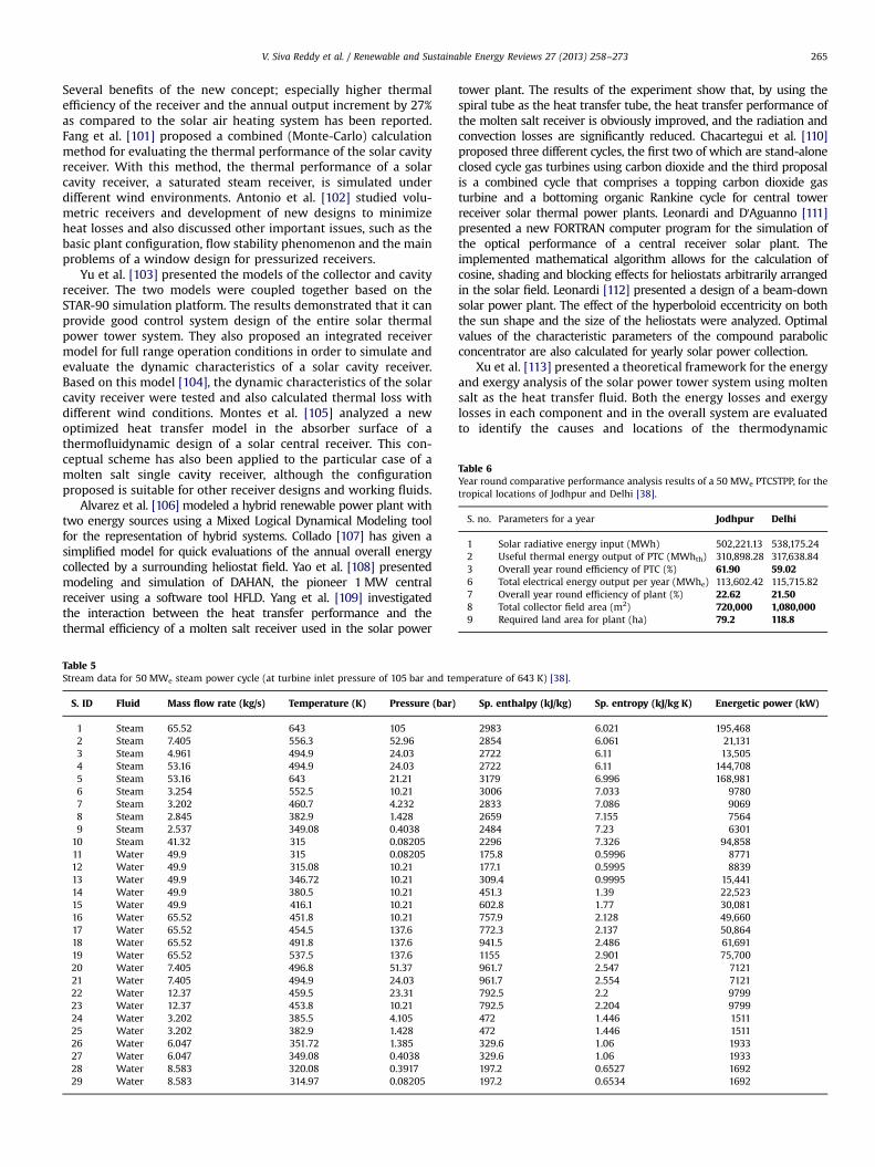
Table 6Year round comparative performance analysis results of a 50 MWe PTCSTPP, for thetropical locations of Jodhpur and Delhi [38].
S. no. Parameters for a year Jodhpur Delhi
1 Solar radiative energy input (MWh) 502,221.13 538,175.242 Useful thermal energy output of PTC (MWhth) 310,898.28 317,638.843 Overall year round efficiency of PTC (%) 61.90 59.026 Total electrical energy output per year (MWhe) 113,602.42 115,715.827 Overall year round efficiency of plant (%) 22.62 21.508 Total collector field area (m2) 720,000 1,080,0009 Required land area for plant (ha) 79.2 118.8
V. Siva Reddy et al. / Renewable and Sustainable Energy Reviews 27 (2013) 258–273 265
Several benefits of the new concept; especially higher thermalefficiency of the receiver and the annual output increment by 27%as compared to the solar air heating system has been reported.Fang et al. [101] proposed a combined (Monte-Carlo) calculationmethod for evaluating the thermal performance of the solar cavityreceiver. With this method, the thermal performance of a solarcavity receiver, a saturated steam receiver, is simulated underdifferent wind environments. Antonio et al. [102] studied volu-metric receivers and development of new designs to minimizeheat losses and also discussed other important issues, such as thebasic plant configuration, flow stability phenomenon and the mainproblems of a window design for pressurized receivers.
Yu et al. [103] presented the models of the collector and cavityreceiver. The two models were coupled together based on theSTAR-90 simulation platform. The results demonstrated that it canprovide good control system design of the entire solar thermalpower tower system. They also proposed an integrated receivermodel for full range operation conditions in order to simulate andevaluate the dynamic characteristics of a solar cavity receiver.Based on this model [104], the dynamic characteristics of the solarcavity receiver were tested and also calculated thermal loss withdifferent wind conditions. Montes et al. [105] analyzed a newoptimized heat transfer model in the absorber surface of athermofluidynamic design of a solar central receiver. This con-ceptual scheme has also been applied to the particular case of amolten salt single cavity receiver, although the configurationproposed is suitable for other receiver designs and working fluids.
Alvarez et al. [106] modeled a hybrid renewable power plant withtwo energy sources using a Mixed Logical Dynamical Modeling toolfor the representation of hybrid systems. Collado [107] has given asimplified model for quick evaluations of the annual overall energycollected by a surrounding heliostat field. Yao et al. [108] presentedmodeling and simulation of DAHAN, the pioneer 1 MW centralreceiver using a software tool HFLD. Yang et al. [109] investigatedthe interaction between the heat transfer performance and thethermal efficiency of a molten salt receiver used in the solar power
Table 5Stream data for 50 MWe steam power cycle (at turbine inlet pressure of 105 bar and te
S. ID Fluid Mass flow rate (kg/s) Temperature (K) Pressure (bar)
1 Steam 65.52 643 1052 Steam 7.405 556.3 52.963 Steam 4.961 494.9 24.034 Steam 53.16 494.9 24.035 Steam 53.16 643 21.216 Steam 3.254 552.5 10.217 Steam 3.202 460.7 4.2328 Steam 2.845 382.9 1.4289 Steam 2.537 349.08 0.4038
10 Steam 41.32 315 0.0820511 Water 49.9 315 0.0820512 Water 49.9 315.08 10.2113 Water 49.9 346.72 10.2114 Water 49.9 380.5 10.2115 Water 49.9 416.1 10.2116 Water 65.52 451.8 10.2117 Water 65.52 454.5 137.618 Water 65.52 491.8 137.619 Water 65.52 537.5 137.620 Water 7.405 496.8 51.3721 Water 7.405 494.9 24.0322 Water 12.37 459.5 23.3123 Water 12.37 453.8 10.2124 Water 3.202 385.5 4.10525 Water 3.202 382.9 1.42826 Water 6.047 351.72 1.38527 Water 6.047 349.08 0.403828 Water 8.583 320.08 0.391729 Water 8.583 314.97 0.08205
tower plant. The results of the experiment show that, by using thespiral tube as the heat transfer tube, the heat transfer performance ofthe molten salt receiver is obviously improved, and the radiation andconvection losses are significantly reduced. Chacartegui et al. [110]proposed three different cycles, the first two of which are stand-aloneclosed cycle gas turbines using carbon dioxide and the third proposalis a combined cycle that comprises a topping carbon dioxide gasturbine and a bottoming organic Rankine cycle for central towerreceiver solar thermal power plants. Leonardi and D'Aguanno [111]presented a new FORTRAN computer program for the simulation ofthe optical performance of a central receiver solar plant. Theimplemented mathematical algorithm allows for the calculation ofcosine, shading and blocking effects for heliostats arbitrarily arrangedin the solar field. Leonardi [112] presented a design of a beam-downsolar power plant. The effect of the hyperboloid eccentricity on boththe sun shape and the size of the heliostats were analyzed. Optimalvalues of the characteristic parameters of the compound parabolicconcentrator are also calculated for yearly solar power collection.
Xu et al. [113] presented a theoretical framework for the energyand exergy analysis of the solar power tower system using moltensalt as the heat transfer fluid. Both the energy losses and exergylosses in each component and in the overall system are evaluatedto identify the causes and locations of the thermodynamic
mperature of 643 K) [38].
Sp. enthalpy (kJ/kg) Sp. entropy (kJ/kg K) Energetic power (kW)
2983 6.021 195,4682854 6.061 21,1312722 6.11 13,5052722 6.11 144,7083179 6.996 168,9813006 7.033 97802833 7.086 90692659 7.155 75642484 7.23 63012296 7.326 94,858175.8 0.5996 8771177.1 0.5995 8839309.4 0.9995 15,441451.3 1.39 22,523602.8 1.77 30,081757.9 2.128 49,660772.3 2.137 50,864941.5 2.486 61,6911155 2.901 75,700961.7 2.547 7121961.7 2.554 7121792.5 2.2 9799792.5 2.204 9799472 1.446 1511472 1.446 1511329.6 1.06 1933329.6 1.06 1933197.2 0.6527 1692197.2 0.6534 1692

V. Siva Reddy et al. / Renewable and Sustainable Energy Reviews 27 (2013) 258–273266
imperfection. The results show that the maximum exergy lossoccurs in the receiver system, followed by the heliostat fieldsystem, although main energy loss occurs in the condenser ofthe power cycle system. They also presented model of 1 MWDahan solar thermal power tower plant using mathematicalmodular modeling method. The dynamic and static characteristicsof the power plant are analyzed based on these models [114].
From the above reported findings, the technical viability andreliability of the medium and high temperature solar thermal powerplants is proved. Another most important issue for commercializationof the technologies is the system cost. Reported installation costs ofPDCSSPP are very high, i.e., approximately $10,000 per kW. However,it is estimated that the cost of the system may reduce to $2500 perkW, if there is installations of more units (i.e., 500 units per year). Theinstallation cost of CTRSTPP is also reported higher, i.e. $ 14,000 perkW [1]. In the present paper, the authors have tried to highlight thecase studied on economical feasibility of the PTCSTPP, PDCSSPP, andCTRSTPP solar thermal power plants for the locations of Jodhpur andDelhi in India [123] with reference to published works of the authorselsewhere. It will be very helpful in further design and developmentof solar thermal power plants anywhere in the world, especiallyin India.
Fig.3. Variation of unit (kWhe) electric energy generation cost (UC) with interestrate (%) of PTCSTPP for the Jodhpur location [123].
Fig. 4. Variation of unit (kWhe) electric energy generation cost (UC) with interestrate (%) of PTCSTPP for the Delhi location [123].
4. Economic assessment of low, medium and hightemperature solar thermal power plants for Indian tropicalclimates—case studies
Study of the year round performance of low, medium and hightemperature solar thermal power plants for Indian tropical cli-mates is scant in literature for determining the unit cost of solarthermal power generation. In the present study, economicalassessments of the solar thermal power generation option basedon different concentration technologies have been done. A reason-able capacity of 50 MW has been considered at two selectivetropical locations of India, i.e., Jodhpur and Delhi. The DNI,ambient temperature and wind velocities for selected Indianlocations are collected from EERE [115] website.
These costs have been estimated according to system advisormodel [116] and the dollar is converted into Indian rupees($1¼ INR 50 as on November 10, 2011).
First of all the annual electricity production is estimated in eachcase, then economic analysis is performed to calculate the cost ofthe unit (kWhe) electric energy generation cost (UC), which can beused to compare different locations [117,118].
UC¼ CRF � CIN þ COM þ CF
ENETð1Þ
Table 7Cost data for economical analysis of 50 MWe PTCSTPP, for the tropical locations of Jodh
Total product cost Cost [116] Jodhpur
Direct costSite improvements 150 INR/m2 792,000 m2
Cost of collector 19,250 INR/m2 276,480 m2
Storage 4000 INR/kWht 110,000 kWht
Power plant 47,000 INR/kWe 55,000 kWe
Total direct cost
Indirect costProcure, construction and execution 11% direct cost 9,337,240,000Project, land, miscellaneous 2% direct cost 9,337,240,000Total indirect costTotal (direct +indirect) cost
Operation and maintenance costsFixed cost by capacity 3500 INR/kW/year 55,000 kW/yeaVariable cost by generation 150 INR/MWhe 113,602.42 MWTotal (O&M) cost
where CRF is uniform series capital recovery factor [119].
CRF¼ ið1þ iÞnð1þ iÞn�1
� �ð2Þ
where CIN is installation cost, COM is operation & maintenance cost,and CF is fuel cost. In this analysis, taxes, incentives, and insuranceare not considered. Interest rate (i) (%) and lifespan (n) of a powerplant (years) are taken into account.
pur and Delhi [123].
Delhi Total cost (Jodhpur) Total cost (Delhi)
INR (Lakhs) INR (Lakhs)1,188,000 m2 9900.00 14,850.00414,720 m2 53,222.40 79,833.60110,000 kWht 4400.00 4400.0055,000 kWe 25,850.00 25,850.00
93,372.40 124,933.60
12,493,360,000 10,270.96 13,742.7012,493,360,000 1867.45 2498.67
12,138.41 16,241.37105,510.81 141,174.97
r 55,000 kW/year 1925.00 1925.00he 115,715.82 MWhe 170.40 173.57
2095.40 2098.57

V. Siva Reddy et al. / Renewable and Sustainable Energy Reviews 27 (2013) 258–273 267
4.1. Techno-economic analysis of PTCSTPP
The solar thermal power system reported in the present studyhas 80 loops of the parabolic trough collector array oriented N–Saxis and E–W operating in a tracking mode [38]. The collector–receiver subsystem and Rankine heat engine subsystem are shownin Fig. 2. Therminol VP-1 oil at 566 K is pumped from a ‘cold’storage tank through the receiver where it is heated to 643 K andthen on to a ‘hot’ tank for storage. The design parameters of theparabolic collector loop are given in Table 4. The property data atthe various stream state points of a 50 MWe steam power plantcycle are shown in Table 5 having the HPT inlet pressure of 105 barand temperature of 643 K.
Based on the performance analysis carried out by Siva Reddyet al. [38], a detailed comparative performance result of 50 MWe
PTCSTPP for the locations of Jodhpur and Delhi is presented inTable 6. For Jodhpur location with 79.2 ha land area and havingsolar radiative energy input of 502.2�103 MWh per annum,113.6�103 MWhe power production has been estimated. In thesimilar fashion for Delhi location, with 118.8 ha land area andhaving solar radiative energy input of 538�103 MWh per annum,115.7�103 MWhe power production has been estimated. Perfor-mance efficiency of the PTCSTPP at the location of Jodhpur andDelhi is found to be 22.62%, 21.50% respectively.
Data for economic analysis are shown in Table 7. These costshave been evaluated according to System Advisor Model [116]from National Renewable Energy Laboratory. Eqs. (1) and (2) areused for determining unit electrical energy generation cost. Theinstallation and operation and maintenance cost of the PTCSTPPaccording to the selected Indian tropical climates like Jodhpur andDelhi have been estimated.
The installation cost per MWe electrical capacity is INR 21.10crore for Jodhpur and INR 28.23 crore for Delhi based on the solarintensity availability. INR 41.91 lakhs and INR 41.97 lakhs asoperation and maintenance cost per MWe electrical capacity forthe locations of Jodhpur and Delhi respectively. Variation of unit(kWhe) electric energy generation cost (UC) with interest rate (%)for different lifespan of a power plant at Jodhpur and Delhi has
Cooling Tower
CP
Parabolic dish
Heat exchanger
Fig. 5. Simplified schematic view of the 50 MWe parabolic di
been shown in Figs. 3 and 4. Unit cost is varying from INR 7 to 17and INR 9 to 22 with interest rate for different lifespan of thePTCSTPP for the locations of Jodhpur and Delhi. For differentlifespan of power plant, unit (kWhe) electric energy generationcost increases linearly with respect to the interest rate (%). Theeffect of the interest rate is more as compared to the lifespan of thepower plant. At general condition (30 years life span of the plantand 10% interest rate) unit (kWhe) electric energy generating costis obtained as INR 11.70 and INR 14.76 respectably for the locationJodhpur and Delhi.
4.2. Techno-economic analysis of PDCSSPP
The PDCSSPP system considered here consists of a parabolicdish concentrator, receiver and Stirling engine as illustrated inFig. 5. There is a dual axis tracking system with parabolic dishmirror to concentrate solar radiation on a receiver which is anintegral part of Stirling engine. Heat pipe absorbers are used totransfer available heat energy into it. In the present analysis,designed capacity of 50 MWe is considered in which the parabolicdish system of 25 kWe is arranged in a matrix form like 50�40 of2000 units of the design capacity resulting 50 MWe. Three stars inFig. 5 depict that there is a series of parabolic dish concentratingsolar Stirling engines in between which cannot be shown. Thedesigned data for 25 kWe is shown in Tables 8 and 9.
The performance of the PDCSSPP has given better efficiency inJodhpur as compared to Delhi, due to high DNI availability.Table 10 shows detailed comparative performance results of50 MWe PDCSSPP for the locations of Jodhpur and Delhi. For theJodhpur location with 98.32 ha land area, it can produce95.77�103 MWhe at a solar radiative energy input of 384.06�103 MWh per annum. For the Delhi location with 122.74 ha landarea, it can produce 86.21�103 MWhe at a solar radiative energyinput 347.61�103 MWh per annum.
Data for economic analysis are shown in Table 11. These costshave been carefully taken according to System Advisor Model(2011). INR13 and INR 15 crore as installation cost per MWe
electrical capacity for the location Jodhpur and Delhi, INR 28 lakhs
2D
2D
CP
Stirling engine
sh concentrating solar Striling engine power plant [120].

V. Siva Reddy et al. / Renewable and Sustainable Energy Reviews 27 (2013) 258–273268
as operation and maintenance cost per MWe electrical capacity forthought out the year the year. Variation of unit (kWhe) electricenergy generation cost (UC) with interest rate (%) for differentlifespan of a solar power plant, for the locations Jodhpur and Delhihave been shown in Figs.6 and 7 respectively. Unit cost is varyingfrom INR 5 to INR 12 for the location Jodhpur and INR 7 to INR 16for the location Delhi with respect to interest rate. In bothlocations for different lifespan of power plant, unit (kWhe) electricenergy generation cost increases linearly with respect to interestrate (%). At general condition (30 years life span of the plant and
Table 9Design characteristics of a PDCSSPP (50 MWe) for Jodhpur and Delhi [120,123].
Design point parametersNumber of parabolic dish systemsGross power rating of each parabolic dish system (kW)Longitude (deg)Latitude (deg)Designed solar irradiance (W/m2)Power consumption for cooling tower system, power needed for the tracking
ConcentratorAperture diameter (m)Aperture area (m2)Glass area (m2)
Table 8Design characteristics of a solar parabolic dish-Stirling engine (25 kWe) [121,122].
ConcentratorAperture diameter (m) 10.57Aperture area (m2) 91.01Glass area (m2) 87.67Focal length (m) 7.45Rim angle (deg) 39Intercept factor, IF 0.92Mirror reflectivity, γr 0.92Cavity absorptivity, αc 0.94Losses due dust on the envelope,ηd
0.98
Cavity emissivity, εc 0.90Module dimensions 11.89 m H, 11.28 mWModule weight (kg) 6.934Tracking Azimuth/elevationCavity diameter (mm) 450 (Inconel 625 material)Absorber diameter (mm) 200Gas operating temperature (K) 1033Max tube temperature (K) 1083
Stirling engine (kinematic)Engine dry weight (kg) 225Displacement volume (cm3) 4�95Bore and stroke (mm) 55 and 40Regenerators 4�2@44 mm long, 57 mm diameter,
holding 200 mesh stainless steel wirescreens
Number of pistons 4. double actingWorking fluid H2 or HeWorking fluid pressure (max)(MPa)
20
Operating temperature (1C) 720Power control Fluid pressureCooling WaterOutput power 27 kW (max), 22 kW (rated)
Power conversion unitAlternator Induction, 1800 rpmAlternator efficiency (%) 92–94Electric energy 480 V, 60 Hz, three phaseGross power rating (kW) 25 at 1000 W/m2
Minimum solar insolation (W/m2)
250–300
10% interest rate) unit (kWhe) electric energy generating costobtained as INR 8.76 and INR 11.06 for the locations, Jodhpurand Delhi respectively.
4.3. Techno-economic analysis of CTRSTPP
In this case study heliostat field-receiver subsystem as shown inFig. 8 consists of heliostats and volumetric air receiver at the focalpoint on the central tower. Heliostats array consists of 2545 collectorsfor Jodhpur and 3530 collectors for Delhi based on the DNIavailability to obtain design operating temperature of air (973 K).Each heliostat module is made up of 10.5�11 m2 dimension with aneffective reflector area of 100 m2. The height of the central towerreceiver has been considered as 150 m. The various design para-meters of the central tower receiver are given in Table 12. TheRankine heat engine model is considered for single reheating foravoiding dryness fraction in the last stage of low pressure turbine.Table 13 shows the property data of the stream at different statepoints for a 50 MWe steam power plant cycle at the HPT inletpressure and temperature 185 bar and 813 K respectively.
Table 14 shows detailed comparative performance resultsof 50 MWe CTRSTPP for the locations of Jodhpur and Delhi. Forthe Jodhpur location with 146.3 ha land area, it can produce123.07�103 MWhe at a solar radiative energy input of 490.76�103 MWh per year. For the Delhi location with 257.3 ha land area,it can produce 124.88�103 MWhe at a solar radiative energy input487.43�103 MWh per year.
The simple formulation for unit (kWhe) electric energy gen-eration cost (UC) was as given in Eqs. (1) and (2). Input/Outputdata for economic analysis is shown in Table 15. The installation,operation & maintenance cost of the CTRSTPP according to theselected Indian tropical climates like Jodhpur and Delhi has beenestimated. The installation cost per MWe electrical capacity is foundto be INR 23.56 crore for Jodhpur and INR 28.40 crore for Delhi basedon the solar intensity availability. While the operation and main-tenance costs INR 42.19 lakhs and INR 42.25 lakhs per MWe electricalcapacity for the locations of Jodhpur and Delhi respectively. Variation
Jodhpur Delhi
2000 200025 2573.017E 77.18E26.28N 28.57N1000 (DNI) 800 (DNI)0.03�output power 0.03�output power
10.57 11.8191.01 113.8187.67 109.57
Table 10Year round comparative performance analysis results of a 50 MWe PDCSSPP, for thetropical locations of Jodhpur and Delhi [120,123].
S. no. Parameters for a year Jodhpur Delhi
1 Solar radiative energy input (MWh) 384,062.94 347,608.372 Useful thermal energy output of PDC (MWhth) 292,880.33 265,225.683 Overall year round efficiency of PDC (%) 76.26 76.034 Electric energy output (MWhe) 95,775.3 86,206.725 Overall year round efficiency of plant (%) 24.93 24.806 Total collector field area (m2) 893,800 1,115,8097 Required land area for plant (ha) 98.32 122.74

Fig. 7. Variation of unit (kWhe) electric energy generation cost (UC) with interestrate (%) of PDCSSPP for the Delhi location [123].
Table 12Geometrical and optical parameters for the heliostat field considered [86].
Heliostat dimension (m�m) 10.5�11Reflective area per generic heliostat (m�m) 10�10Incident power (MWt) 197Receiver elevation (above ground) (m) 150Receiver shape Half cylinderTilt of absorber plane (deg) 15Receiver rated output (MWt) 134Exit air temperature (K) 973Return air temperature (K) 473Design point parameters (Jodhpur)
Number of heliostat 2545Solar beam radiation (W/m2) 870Longitude (deg) 73.017ELatitude (deg) 26.28N
Design point parameters (Delhi)Number of heliostat 3530Solar beam radiation (W/m2) 620Longitude (deg) 77.18ELatitude (deg) 28.57N
Tracking Azimuth/elevationOptical parameters for the collectorIntercept factor, IF 0.92Mirror reflectivity, γr 0.92Cavity absorptivity, αc 0.94Losses due dust on the envelope, ηd 0.98Cavity emissivity, εc 0.90
Table 11Cost data for economical analysis of 50 MWe PDCSSPP, for the tropical locations of Jodhpur and Delhi [120,123].
Total product cost Cost [116] Jodhpur Delhi Total cost (Jodhpur) Total cost (Delhi)
Direct cost INR (Lakhs) INR (Lakhs)Site improvements 150 INR/m2 893,800 m2 1,115,809 m2 1340.70 1673.71Cost of collector 20,000 INR/m2 182,020 m2 227,620 m2 36,404.00 45,524.00Receiver cost 12500 INR/kW 55,000 kW 55,000 kW 6875.00 6875.00Engine cost 25,000 INR/kW 55,000 kW 55,000 kW 13,750.00 13,750.00Total direct cost 58,369.70 67,822.71
Indirect costProcure, construction & execution 11% Direct cost 5,836,969,880 6,782,271,320 6420.67 7460.50Project, land, miscellaneous 2% Direct cost 5,836,969,880 6,782,271,320 1167.39 1356.45Total indirect cost 7588.06 8816.95Total (direct +indirect) cost 65,957.76 76,639.67
Operation and maintenance costsFixed cost by capacity 2500 INR/kW/year 55,000 kW/year 55,000 kW/year 1375.00 1375.00Variable cost by generation 35 INR/MWhe 95,775.3 MWhe 86,206.7 MWhe 33.52 30.17Total (O&M) cost 1408.52 1405.17
Fig. 6. Variation of unit (kWhe) electric energy generation cost (UC) with interestrate (%) of PDCSSPP for the Jodhpur location [120].
V. Siva Reddy et al. / Renewable and Sustainable Energy Reviews 27 (2013) 258–273 269
of unit (kWhe) electric energy generation cost (UC) with interest rate(%) for different lifespan of a power plant at Jodhpur and Delhi hasbeen shown in Figs. 9 and 10. Unit cost is varying from INR 5 to 16and INR 7 to 19 with interest rate for different lifespan of the CTRSTPPfor the locations of Jodhpur and Delhi. For different lifespan of powerplant, unit (kWhe) electric energy generation cost increases linearlywith respect to the interest rate (%). The effect of the interest rate is
more as compared to the lifespan of the power plant. At general basecondition (30 years life span of the solar plant and 10% interest rate),the unit (kWhe) electric energy generating cost is obtained as INR10.09 and INR 12.10 for the location of Jodhpur and Delhi respectively.
5. Conclusions
Based on the present literature review, the authors concludethat there is no doubt in the technical feasibility of solar thermalpower plants for commercialization in the present scenario. Thereis a need to substitute the demand of power with solar energy toreduce the rate of consumption of fossil fuels and consequentlyreducing green house gas emissions. The performance and eco-nomic analysis carried out for the solar thermal power plants(PTCSTPP, PDCSSPP, and CTRSTPP) for the locations of Jodhpur andDelhi to explore the possibility of solar thermal power generationin India is presented here. The estimated unit (kWhe) electric

Table 13Stream data for 50 MWe Steam power cycle (at turbine inlet pressure of 185 bar and temperature of 813 K) [123].
S. ID Fluid Mass flow (kg/s) Temperature (K) Pressure (bar) Sp. enthalpy (kJ/kg) Sp. entropy (kJ/kg K) Energetic power (kW)
1 Steam 55.63 813 185 3382 6.352 188,1262 Steam 6.275 705.4 93.31 3204 6.395 20,1023 Steam 4.851 611.5 46.25 3047 6.447 14,7804 Steam 44.5 611.5 46.25 3047 6.447 135,5855 Steam 44.5 753 40.82 3398 7.02 151,2456 Steam 2.978 637.8 17.98 3173 7.062 94527 Steam 2.916 533.5 7.456 2974 7.115 86728 Steam 2.54 429.1 2.516 2777 7.196 70549 Steam 2.884 363.36 0.712 2590 7.281 7471
10 Steam 33.19 315 0.082 2325 7.42 77,16511 Water 41.53 315 0.082 175.8 0.598 729812 Water 41.53 315.17 17.98 178.2 0.601 739813 Water 41.53 360.92 17.98 369.5 1.167 15,34514 Water 41.53 398.1 17.98 526.7 1.581 21,87115 Water 41.53 437.8 17.98 697.1 1.989 28,94716 Water 55.63 477.8 17.98 874.2 2.376 48,63017 Water 55.63 482.6 214.6 903.4 2.39 50,25818 Water 55.63 528.8 214.6 1114 2.805 61,94619 Water 55.63 575.7 214.6 1347 3.227 74,91020 Water 6.275 533.8 90.98 1138 2.879 713921 Water 6.275 532.1 46.25 1138 2.89 713922 Water 11.13 487.6 45.09 919.5 2.463 10,23123 Water 11.13 480.1 44.86 919.5 2.47 10,23124 Water 2.916 403.1 7.23 547.3 1.636 159625 Water 2.916 400.6 7.23 547.3 1.637 159626 Water 5.456 365.92 2.44 389.4 1.226 212427 Water 5.456 363.36 0.712 389.4 1.227 212428 Water 8.34 320.17 0.687 197.5 0.667 164829 Water 8.34 314.97 0.082 197.5 0.668 1648
Deaerator
7
C
LPH1LPH2LPH3
HPH1
1213
20
16
18
8
5
2
11
1
4
19 3
22
6
15
BFP
17
Boiler
EXP1
G
109
HPH2
LPT
14
EXP2CEP
HP-Drum
1
HPT
a
b
21
23
25 29
Storage
Tank
24 26 2827
EXP3 EXP4 EXP5
To(973K)
Solar
Radiation
Ti(563K)
Heliostat Field
Central Receiver Air flow
Fig. 8. Simplified schematic view of the 50 MWe central tower receiver solar thermal power plant [123].
Table 14Year round comparative performance analysis results of a 50 MWe CTRSTPP, for the tropical locations of Jodhpur and Delhi [123].
S. no. Parameters for a year Jodhpur Delhi
1 Solar radiative energy input (MWh) 49,0759.6 48,7434.522 Useful thermal energy output of CTR (MWhth) 310,262.67 314,846.763 Overall year round thermal efficiency of CTR (%) 63.22 64.594 Total electric energy output per year (MWhe) 123,066.44 124,884.735 Overall year round efficiency of plant 25.08 25.626 Total collector field area (m2) 1,323,966 2,340,1717 Required land area for plant (ha) 146.3 257.3
V. Siva Reddy et al. / Renewable and Sustainable Energy Reviews 27 (2013) 258–273270

Fig. 9. Variation of unit (kWhe) electric energy generation cost (UC) with interestrate (%) of CTRSTPP for the Jodhpur location [123].
Fig. 10. Variation of unit (kWhe) electric energy generation cost (UC) with interestrate (%) of CTRSTPP for the Delhi location [123].
Table 15Cost data for economical analysis of 50 MWe CTRSTPP, for the tropical locations of Jodhpur and Delhi [123].
Total product cost Cost [86,116] Jodhpur Delhi Total cost (Jodhpur) Total cost (Delhi)
Direct cost INR (Lakhs) INR (Lakhs)Site improvements 150 INR/m2 1,456,362.6 m2 2,574,188.1 m2 2184.54 3861.28Cost of collector 20,000 INR/m2 254,500 m2 353,000 m2 50,900.00 70,600.00Receiver cost 42,000 INR/kWe 55,000 55,000 23,100.00 23,100.00Storage 1500 INR/kWht 110,000 kWht 110,000 kWht 1650.00 1650.00Tower cost 400,000 INR/m 150 m 150 m 600.00 600.00Power plant 47,000 INR/kWe 55,000 kWe 55,000 kWe 25,850.00 25,850.00Total direct cost 104,284.54 125,661.28
Indirect costProcure, construction and execution 11% Direct cost 10,428,454,390 12,566,128,215 11,471.30 13,822.74Project, land, miscellaneous 2% Direct cost 10,428,454,390 12,566,128,215 2085.69 2513.23Total indirect cost 13,556.99 16,335.97Total (direct +indirect) cost 117,841.53 141,997.25Per MW installation cost 2356.83 2839.94
Operation and maintenance costsFixed cost by capacity 3500 INR/kW/year 55000 kW/year 55,000 kW/year 1925.00 1925.00Variable cost by generation 150 INR/MWhe 123,066.44 MWhe 124,884.73 MWhe 184.60 187.33Total (O&M) cost 2109.60 2112.33Per MW O&M cost 42.19 42.25
V. Siva Reddy et al. / Renewable and Sustainable Energy Reviews 27 (2013) 258–273 271
energy generating cost for PTCSTPP is found to be INR 11.70 andINR 14.76. While unit (kWhe) electric energy generating cost forPDCSSPP is estimated as INR 8.76 and INR 11.06 and the same forCTRSTPP is INR 10.09 and INR 12.10 for the locations Jodhpur andDelhi with the same lifespan (30 years) of the solar power plantsand interest rate (10%) on investment. The unit power generationcost of the PDCSSPP is less than the PTCSTPP and CTRSTPP becauseits efficiency is high. However, the year round power output fromthe PDCSSPP is less compared to PTCSTPP and CTRSTPP; the mainreason for this is that the PTCSTPP and CTRSTPP systems havethermal storage facility. PDCSSPP system is required to bedesigned at maximum DNI availability, because of no storagefacility available to the system itself. Fluctuation in power outputwill take place with this system.
Above findings may motivate the researchers and policy makersto design and develop suitable solar thermal power plants for Indianclimatic conditions based on the experience gained from the otherpart of the world. If the energy losses at various locations, such asproduction, transmission and distributions from power producedthrough conventional thermal power plants and environmentaldegradation impacts is taken into account, the cost of solar powermay become competitive very soon. It is observed that the solarthermal power plants have come out of the experimental stage tocommercial applications.
References
[1] Sukhatme SP, Nayak JK. Solar energy: principles of thermal collection andstorage. New Delhi: Tata McGraw Hill; 2011.
[2] Prisyazhniuk VA. Alternative trends in development of thermal power plants.Applied Thermal Engineering 2008;28:190–4.
[3] Price H, Lupfert E, Kearney D, Zarza E, Cohen G, Gee R, et al. Advances inparabolic trough solar power technology. Journal of Solar Energy Engineer-ing 2002;124:109–25.
[4] Kalogirou SA. Solar energy engineering: processes and systems. AcademicPress, Elsevier Inc. United States of America; 2009.
[5] Kearney DW, Price HW. Solar thermal plants—LUZ concept (current status ofthe SEGS plants). In: Proceedings of the second renewable energy congress,UK, 1992; vol. 2: p. 582–8.
[6] Lupfert E, Geyer M, Schiel W, Zarza E, Gonzalez-Anguila RO, Nava P.Eurotrough—a new parabolic trough collector with advanced light weightstructure. In: Proceedings of solar thermal 2000 international conference onCD ROM, Sydney, Australia; 2000.
[7] Geyer M, Lupfert E, Osuna R, Zarza E, Nava P, Langenkamp J, et.al. EURO-TROUGH—parabolic trough collector developed for cost efficient solar powergeneration. In: Proceedings of the 11th international symposium on con-centrating solar power and chemical energy technologies, Zurich, Switzer-land; 2002.
[8] Treadwell GW, Grandjean NR, Biggs F. An analysis of the influence ofgeography and weather on parabolic trough solar collector design. Journalof Solar Energy Engineering 1981;103:98–104.
[9] Treadwell GW, Grandjean NR. Systematic rotation and receiver location erroreffects on parabolic trough annual performance. Journal of Solar EnergyEngineering 1982;104:345–8.

V. Siva Reddy et al. / Renewable and Sustainable Energy Reviews 27 (2013) 258–273272
[10] Guven HM, Bannerot RB. Derivation of universal error parameters forcomprehensive optical analysis of parabolic. Journal of Solar Energy Engi-neering 1986;108:275–81.
[11] Guven HM, Mistree F, Bannerot RB, Strategy GD, Design D. A conceptual basisfor the design of parabolic troughs for different. Solar Energy 1986;108:60–6.
[12] Odeh SD, Morrison GL, Behnia M. Modeling of parabolic trough direct steamgeneration solar collectors. Solar Energy 1998;62:395–406.
[13] Tao T, Hongfei Z, Kaiyan H, Mayere A. A new trough solar concentrator andits performance analysis. Solar Energy 2011;85:198–207.
[14] Mullick SC, Nanda SK. An improved technique for computing the heat lossfactor of a tubular absorber. Solar Energy 1989;42:1–7.
[15] Kearney D, Herrmann U, Nava P, Kelly B, Mahoney R, Pacheco J, et al.Assessment of a molten salt heat transfer fluid in a parabolic trough solarfield. Journal of Solar Energy Engineering 2003;125:170.
[16] Bakos GC, Ioannidis I, Tsagas NF, Seftelis I. Design, optimization andconversion efficiency determination of a line-focus parabolic-trough solar-collector (PTC). Applied Energy 2001;68:43–50.
[17] Naeeni N, Yaghoubi M. Analysis of wind flow around a parabolic collector(2) heat transfer from receiver tube. Renewable Energy 2007;32:1259–72.
[18] You Y, Hu EJ. A medium temperature solar thermal power system and itsefficiency optimisation. Solar Energy 2002;22:357–64.
[19] Gang P, Jing L, Jie J. Analysis of low temperature solar thermal electricgeneration using regenerative organic Rankine cycle. Applied ThermalEngineering 2010;30:998–1004.
[20] Fernandez-Garcia A, Zarza E, Valenzuela L, Pérez M. Parabolic-trough solarcollectors and their applications. Renewable and Sustainable Energy Reviews2010;14:1695–721.
[21] Kerkeni C, Benjemaa F, Kooli S, Farhat A, Maalej M. Performance evaluationof a thermodynamic solar power plant: fifteen years of operation history.Renewable Energy 2002;25:473–87.
[22] Lechon Y, de la Rua C, Saez R, Montes MJ, Abanades A, Martinez-Val JM, et al. Lifecycle environmental impacts of electricity production by solar thermal powerplants in Spain. Journal of Solar Energy Engineering 2008;130:021012–7.
[23] Lechon Y, de la Rua C, Saez R, Montes MJ, Abanades A, Martinez-Val JM, et al.Solar multiple optimization for a solar-only thermal power plant, using oil asheat transfer fluid in the parabolic trough collectors. Solar Energy2009;83:2165–76.
[24] Munoz J, Abanades A, Martinez-Val JM. A conceptual design of solar boiler.Solar Energy 2009;83:1713–22.
[25] Mohammed S, Al-Soud MS, Hrayshat ES. A 50 MW concentrating solarpower plant for Jordan. Journal of Cleaner Production 2009;17:625–35.
[26] Birnbaum J, Eck M, Fichtner M, Hirsch T, Lehmann D, Zimmermann GA.Direct steam generation solar power plant with integrated thermal storage.Journal of Solar Energy Engineering 2010;132:031014–5.
[27] Yan Q, Hu E, Yang Y, Zhai R. Dynamic modeling and simulation of a solardirect steam-generating system. International Journal of Energy Research2010;34:1341–55.
[28] Garcia IL, Luis A, Blanco D. Performance model for parabolic trough solarthermal power plants with thermal storage: comparison to operating plantdata. Solar Energy 2011;85:2443–60.
[29] Montes MJ, Rovira A, Muñoz M, Martínez-val JM. Performance analysis of anintegrated solar combined cycle using direct steam generation in parabolictrough collectors. Applied Energy 2011;88:3228–38.
[30] Garcia-Barberena J, Garcia P, Sanchez M, Blanco MJ, Lasheras C, Padrós A,et al. Analysis of the influence of operational strategies in plant performanceusing SimulCET, simulation software for parabolic trough power plants. SolarEnergy 2012;86:53–63.
[31] Feldhoff JF, Schmitz K, Eck M, Schnatbaum-Laumann L, Laing D, Ortiz-Vives F,et al. Comparative system analysis of direct steam generation and syntheticoil parabolic trough power plants with integrated thermal storage. SolarEnergy 2012;86:520–30.
[32] Bonilla J, Jose L. Parabolic-trough solar thermal power plant simulationscheme, multi-objective genetic algorithm calibration and validation. SolarEnergy 2012;86:531–40.
[33] Kreider JF. Second-law analysis of solar-thermal processes. Energy Research1979;32:325–31.
[34] Singh N, Kaushik SC. Optimum operating temperature and efficiency of solarthermal power-systems. Heat Recovery Systems and CHP 1994;14:633–8.
[35] Singh N, Kaushik SC, Misra RD. Exergetic analysis of a solar thermal powersystem. Renewable Energy 2000;19:135–43.
[36] Gupta MK, Kaushik SC. Exergy analysis and investigation for various feedwater heaters of direct steam generation solar–thermal power plant. Renew-able Energy 2010;35:1228–35.
[37] Montes MJ, Abanades A, Martinez-Val JM. Thermofluidynamic model andcomparative analysis of parabolic trough collectors using oil, water/steam, ormolten salt. Journal of Solar Energy Engineering 2010;132:1–7.
[38] Siva Reddy V, Kaushik SC, Tyagi SK. Exergetic analysis and performanceevaluation of parabolic trough concentrating solar thermal power plant(PTCSTPP). Energy 2012;39:258–73.
[39] Gee RC, Murphy LM. An economic and performance evaluation of parabolictrough component improvements. Journal of Solar Energy Engineering1983;105:10–8.
[40] Luzzi A, Lovegrove K, Filippi E, Fricker H, Schmitz-goeb M, Chandapillai M,et al. Techno-economic analysis of a 10 MWe solar thermal power plantusing ammonia-based thermochemical energy storage. Solar Energy1999;66:91–101.
[41] Quaschning V, Kistner R, Ortmanns W. Influence of direct normal irradiancevariation on the optimal parabolic trough field size: a problem solved withtechnical and economical. Journal of Solar Energy Engineering 2002;124:160–4.
[42] Horn M, Fuhring H, Rheinlander J. Economic analysis of integrated solarcombined cycle power plants a sample case: the economic feasibility of anISCCS power plant in Egypt. Energy 2004;29:935–45.
[43] Hosseini R, Soltani M, Valizadeh G. Technical and economic assessment ofthe integrated solar combined cycle power plants in Iran. Renewable Energy2005;30:1541–55.
[44] Poullikkas A. Economic analysis of power generation from parabolic troughsolar thermal plants for the Mediterranean region—a case study for theisland of Cyprus. Renewable and Sustainable Energy Reviews 2009;13:2474–84.
[45] Laing D, Steinmann WD, Viebahn P, Grater F, Bahl C. Economic analysis andlife cycle assessment of concrete thermal energy storage for parabolic troughpower plants. Journal of Solar Energy Engineering 2010;132:041013–6.
[46] Vallentin D, Viebahn P. Economic opportunities resulting from a globaldeployment of concentrated solar power (CSP) technologies—the example ofGerman technology providers. Energy Policy 2010;38:4467–78.
[47] Feldhoff JF, Benitez D, Eck M, Riffelmann KJ. Economic potential of solarthermal power plants with direct steam generation compared with HTFplants. Journal of Solar Energy Engineering 2010;132:041001–9.
[48] Purohit I, Purohit P. Techno-economic evaluation of concentrating solarpower generation in India. Energy Policy 2010;38:3015–29.
[49] Poullikkas A, Hadjipaschalis I, Kourtis G. The cost of integration of parabolictrough CSP plants in isolated Mediterranean power systems. Renewable andSustainable Energy Reviews 2010;14:1469–76.
[50] Sharaf MA, Nafey AS, García-rodríguez L. Thermo-economic analysis of solarthermal power cycles assisted MED-VC (multi effect distillation-vaporcompression) desalination processes. Energy 2011;36:2753–64.
[51] Spelling J, Favrat D, Martin A, Augsburger G. Thermoeconomic optimizationof a combined-cycle solar tower power plant. Energy 2012;41:113–20.
[52] Zamfirescu C, Dincer I, Stern M, Wagar WR. Exergetic, environmental andeconomic analyses of small-capacity concentrated solar-driven heat enginesfor power and heat cogeneration. International Journal of Energy Research2012;36:397–408, http://dx.doi.org/10.1002/er.
[53] Nixon JD, Davies PA. Cost-exergy optimisation of linear Fresnel reflectors.Solar Energy 2012;86:147–56.
[54] Stine WB, Harrigan RW. Solar energy fundamentals and design withcomputer applications. New York: John Wiley & Sons; 1985.
[55] Mancini T, Heller P, Butler B, Osborn B, Schiel W, Goldberg V, et al. Dish-Stirling systems: an overview of development and status. Journal of SolarEnergy Engineering 2003;125:135.
[56] Clausing AM. An analysis of convective losses from cavity solar centralreceivers. Solar Energy 1981;27:295–300.
[57] Bannister P. Maximization of exergy gain in high temperature solarthermal receivers by choice of pipe radius. Journal of Heat Transfer1991;113:337–40.
[58] Chen J, Yan Z, Chen L, Andresen B. Efficiency bound of a solar-driven Stirlingheat engine system. Energy 1998;812:805–12.
[59] Kaushika ND, Reddy KS. Performance of a low cost solar paraboloidal dish steamgenerating system. Energy Conversion & Management 2000;41:713–26.
[60] Sendhil Kumar N, Reddy KS. Comparison of receivers for solar dish collectorsystem. Energy Conversion and Management 2008;49:812–9.
[61] Reddy KS, Kumar SN. Combined laminar natural convection and surfaceradiation heat transfer in a modified cavity receiver of solar parabolic dish.International Journal of Thermal Sciences 2008;47:1647–57.
[62] Reddy KS, Kumar SN. An improved model for natural convection heat lossfrom modified cavity receiver of solar dish concentrator. Solar Energy2009;83:1884–92.
[63] Prakash M, Kedare SB, Nayak JK. Investigations on heat losses from a solarcavity receiver. Solar Energy 2009;83:157–70.
[64] Wu SY, Xiao L, Cao Y, Li YR. A parabolic dish/AMTEC solar thermal powersystem and its performance evaluation. Applied Energy 2010;87:452–62.
[65] Wu SY, Xiao L, Cao Y, Li YR. Convection heat loss from cavity receiver inparabolic dish solar thermal power system: a review. Solar Energy2010;84:1342–55.
[66] Lovegrove K, Burgess G, Pye J. A new 500 m2 paraboloidal dish solarconcentrator. Solar Energy 2011;85:620–6.
[67] Li L, Dubowsky S. A new design approach for solar concentrating parabolicdish based on optimized flexible petals. Mechanism and Machine Theory2011;46:1536–48.
[68] Li Z, Tang D, Du J, Li T. Study on the radiation flux and temperaturedistributions of the concentrator receiver system in a solar dish/Stirlingpower facility. Applied Thermal Engineering 2011;31:1780–9.
[69] Wu F, Chen L, Wu C, Sun F. Optimum performance of irreversible Stirlingengine with imperfect regeneration. Energy 1998;39:727–32.
[70] Senft JR. Theoretical limits on the performance of Stirling engines. Interna-tional Journal of Energy Research 1998;22:991–1000.
[71] Costea M, Petrescu S, Harman C. The effect of irreversibilities on solar Stirlingengine cycle performance. Energy Conversion 1999;40:1723–31.
[72] Berrin Erbay L, Yavuz H. Optimization of the irreversible Stirling heat engine.International Journal of Energy Research 1999;23:863–73.
[73] Bhattacharyya S, Blanks DA. Design considerations for a power optimizedregenerative endoreversible Stirling cycle. International Journal of EnergyResearch 2000;24:539–47.

V. Siva Reddy et al. / Renewable and Sustainable Energy Reviews 27 (2013) 258–273 273
[74] Senft JR. Optimum Stirling engine geometry. International Journal of EnergyResearch 2002;26:1087–101.
[75] Kaushik SC, Tyagi SK, Bose SK, Singhal MK. Performance evaluation ofirreversible Stirling and Ericsson heat pump cycles. International Journal ofThermal Sciences 2002;41:193–200.
[76] Petrescu S, Costea M, Harman C, Florea T. Application of the direct method toirreversible Stirling cycles with finite speed. International Journal of EnergyResearch 2002;26:589–609.
[77] Kongtragool B, Wongwises S. A review of solar-powered Stirling engines andlow temperature differential Stirling engines. Renewable and SustainableEnergy Reviews 2003;7:131–54.
[78] Timoumi Y, Tlili I, Ben Nasrallah S. Performance optimization of Stirlingengines. Renewable Energy 2008;33:2134–44.
[79] De Boer PCT. Optimal regenerator performance in Stirling engines. Interna-tional Journal of Energy Research 2009;33:813–32.
[80] Karabulut H, Can C, Aksoy F, Serdar Yucesu H. Improved Stirling engineperformance through displacer surface treatment. International Journal ofEnergy Research 2010;34:275–83.
[81] Petrescu S, Petre C, Costea M, Malancioiu O, Boriaru N, Dobrovicescu A, et al.A methodology of computation, design and optimization of solar Stirlingpower plant using hydrogen/oxygen fuel cells. Energy 2010;35:729–39.
[82] Sripakagorn A, Srikam C. Design and performance of a moderate tempera-ture difference Stirling engine. Renewable Energy 2011;36:1728–33.
[83] Yaqi L, Yaling H, Weiwei W. Optimization of solar-powered Stirling heatengine with finite-time thermodynamics. Renewable Energy 2011;36:421–7.
[84] Krishnaiah T, Srinivasa Rao S, Madhumurthy K. Solar Stirling dish powergeneration atlas of India. Cogeneration & Distributed Generation Journal2009;24:35–50.
[85] Becker M, Vant-Hull LL. Thermal receivers. In: Winter CJ, Sizmann RL, Vant-Hull LL, editors. Solar power plants. Berlin: Springer-Verlag; 1991p. 163–97.
[86] Grasse W. PHOEBUS: international 30 MWe solar tower plant. Solar EnergyMaterials 1991;24:82–94.
[87] Romero M, Buck R, Pacheco JE. An update on solar central receiver systems,projects, and technologies. Journal of Solar Energy Engineering2002;124:98–108.
[88] Riaz MRA. Theory of concentrators of solar energy on a central receiver forelectric power generation. Journal of Engineering for Power 1976;98:375–83.
[89] Walzel MD, Lipps FW, Vant-Hull LL. A solar flux density calculation for asolar tower concentrator using a two-dimensional hermite function expan-sion. Solar Energy 1977;19:239–53.
[90] Peterka JA, Tan Z, Cermak JE, Bienkiewicz B. Mean and peak wind loads onheliostats. Journal of Solar Energy Engineering 1989;111:158–64.
[91] Ali BF. Theoretical study of main factors affecting the heliostat field design oftower power plant. Energy Conversion and Management 1990;30:101–6.
[92] Buck R, Brauning T, Denk T, Pfander M, Schwarzbozl P, Tellez F. Solar-hybridgas turbine-based power tower systems (REFOS). Journal of Solar EnergyEngineering 2002;124:2–9.
[93] Schmitz M, Schwarzbozl P, Buck R, Pitzpaal R. Assessment of the potentialimprovement due to multiple apertures in central receiver systems withsecondary concentrators. Solar Energy 2006;80:111–20.
[94] Sanchez M, Romero M. Methodology for generation of heliostat field layoutin central receiver systems based on yearly normalized energy surfaces. SolarEnergy 2006;80:861–74.
[95] Wu Z, Gong B, Wang Z, Li Z, Zang C. An experimental and numerical study ofthe gap effect on wind load on heliostat. Renewable Energy 2010;35:797–806.
[96] Zoschak RJ, Wu SF, Gorman DN. Design and testing of a cavity—receiver for asolar thermal power. Journal of Engineering for Power 1980;102:486–94.
[97] Wu SF, Narayanan TV, Gorman DN. Conceptual design of an advanced water/steam receiver for a solar thermal central power system. Journal of SolarEnergy Engineering 1983;105:34–41.
[98] Carotenuto A, Nocera U, Tecchio P. Thermal behavior of a multi-cavityvolumetric solar receiver: design and tests results. Solar Energy 1993;50:113–21.
[99] Eck M, Buck R, Wittmann M. Dual receiver concept for solar towers up to100 MW. Journal of Solar Energy Engineering 2006;128:293–301.
[100] Buck R, Barth C, Eck M, Steinmann WD. Dual-receiver concept for solartowers. Solar Energy 2006;80:1249–54.
[101] Fang JB, Wei JJ, Dong XW, Wang YS. Thermal performance simulation of asolar cavity receiver under windy conditions. Solar Energy 2011;85:126–38.
[102] Antonio LA. Volumetric receivers in solar thermal power plants with centralreceiver system technology: a review. Solar Energy 2011;85:891–910.
[103] Yu Q, Wang Z, Xu E. Simulation and analysis of the central cavity receiver'sperformance of solar thermal power tower plant. Solar Energy 2012;86:164–74.
[104] Yu Q, Wang Z, Xu E, Li X, Guo M. Modeling and dynamic simulation of thecollector and receiver system of 1 MWe DAHAN solar thermal power towerplant. Renewable Energy 2012;43:18–29.
[105] Montes MJ, Rovira A, Martínez-val JM, Ramos A. Proposal of a fluid flowlayout to improve the heat transfer in the active absorber surface of solarcentral cavity receivers. Applied Thermal Engineering 2012;35:220–32.
[106] Alvarez JD, Guzman JL, Yebra LJ, Berenguel M. Simulation modelling practiceand theory hybrid modeling of central receiver solar power plants. Simula-tion Modelling Practice and Theory 2009;17:664–79.
[107] Collado FJ. Preliminary design of surrounding heliostat fields. RenewableEnergy 2009;34:1359–63.
[108] Yao Z, Wang Z, Lu Z, Wei X. Modeling and simulation of the pioneer 1 MWsolar thermal central receiver system in China. Renewable Energy2009;34:2437–46.
[109] Yang M, Yang X, Yang X, Ding J. Heat transfer enhancement and performanceof the molten salt receiver of a solar power tower. Applied Energy2010;87:2808–11.
[110] Chacartegui R, Muñoz de Escalona JM, Sánchez D, Monje B, Sánchez T.Alternative cycles based on carbon dioxide for central receiver solar powerplants. Applied Thermal Engineering 2011;31:872–9.
[111] Leonardi E, D'Aguanno B. CRS4-2: a numerical code for the calculation of thesolar power collected in a central receiver system. Energy 2011;36:4828–37.
[112] Leonardi E. Detailed analysis of the solar power collected in a beam-downcentral receiver system. Solar Energy 2012;86:734–45.
[113] Xu C, Wang Z, Li X, Sun F. Energy and exergy analysis of solar power towerplants. Applied Thermal Engineering 2011;31:3904–13.
[114] Xu E, Yu Q, Wang Z, Yang C. Modeling and simulation of 1 MW DAHAN solarthermal power tower plant. Renewable Energy 2011;36:848–57.
[115] Energy Efficiency & Renewable energy (EERE). Available from: ⟨http://apps1.eere.energy.gov/buildings/energyplus/cfm/weather_data3.cfm/region=2_asia_wmo_region_2/country=IND/cname=India,http:/www.eere.energy.gov⟩.[Accessed 10.07.11].
[116] System Advisor Model (SAM), sam-win32-2011-6-30, National RenewableEnergy Laboratory. Available from: ⟨https://www.nrel.gov/analysis/sam/downloadVerification.php⟩. [Accessed 12.11.11].
[117] Hosseini R, Soltani M, Valizadeh G. Technical and economic assessment of theintegrated solar combined cycle power plants in Iran. Renewable Energy2005;30:1541–55.
[118] Montes MJ, Abanades A, Martinez-Val JM. Performance of a direct steamgeneration solar thermal power plant for electricity production as a functionof the solar multiple. Solar Energy 2009;83:679–89.
[119] Kandpal TC, Garg HP. Financial evaluation of renewable energy technologies.India: Macmillan India Ltd.; 2003.
[120] Siva Reddy V, Kaushik SC, Tyagi SK. Exergetic analysis and performanceevaluation parabolic dish concentrating solar Stirling engine power plant.International Journal of Energy Research 2012. http://dx.doi.org/10.1002/er.2926.
[121] Stine WB, Diver RBA. Compendium of Solar Dish/Stirling Technology. Vol:SAND 93-7026 UC-236. Sandia National Laboratories; 1994.
[122] Bancha K, Somchai W. A review of solar-powered Stirling engines and lowtemperature differential Stirling engines. Renewable and Sustainable EnergyReviews 2003;7:131–54.
[123] Siva Reddy V. Exergetic analysis and economic evaluation of solar alone andsolar aided thermal power generation (PhD thesis), Centre for EnergyStudies, IIT Delhi, New Delhi; 2012.
Related Documents