ARTICLE IN PRESS Progress in Aerospace Sciences 42 (2006) 285–330 State of the art in wind turbine aerodynamics and aeroelasticity M.O.L. Hansen a, , J.N. Sørensen a , S. Voutsinas b , N. Sørensen c,d , H.Aa. Madsen c a Department of Mechanical Engineering, Technical University of Denmark, Fluids Section, Nils Koppels Alle, Building 403, DK-2800 Lyngby, Denmark b Department of Mechanical Engineering, National Technical University of Athens, Fluids Section, 15780 Zografou, Greece c Wind Energy Department, Risoe National Laboratory, Building VEA-762, P.O. Box 49, Frederiksborgvej 399, DK-4000 Roskilde, Denmark d Department of Civil Engineering, Alborg University, Sohngaardsholmsvej 57, DK 9000 Aalborg, Denmark Available online 29 December 2006 Abstract A comprehensive review of wind turbine aeroelasticity is given. The aerodynamic part starts with the simple aerodynamic Blade Element Momentum Method and ends with giving a review of the work done applying CFD on wind turbine rotors. In between is explained some methods of intermediate complexity such as vortex and panel methods. Also the different approaches to structural modelling of wind turbines are addressed. Finally, the coupling between the aerodynamic and structural modelling is shown in terms of possible instabilities and some examples. r 2006 Elsevier Ltd. All rights reserved. Keywords: Aeroelasticity; Wind turbines Contents 1. Introduction ..................................................................... 286 2. Predicting aerodynamic loads on a wind turbine............................................ 287 2.1. Blade Element Momentum Method ................................................ 287 2.1.1. Dynamic wake/inflow ..................................................... 288 2.1.2. Yaw/tilt model .......................................................... 289 2.1.3. Dynamic stall ........................................................... 289 2.1.4. Airfoil data ............................................................ 290 2.1.5. Wind simulation ......................................................... 290 2.2. Lifting line, panel and vortex models ............................................... 291 2.2.1. Vortex methods ......................................................... 291 2.2.2. Panel methods .......................................................... 292 2.3. Generalized actuator disc models .................................................. 295 2.4. Navier–Stokes solvers .......................................................... 297 2.4.1. Introduction to computational rotor aerodynamics ................................ 297 2.4.2. Approaches ............................................................ 298 2.4.3. Turbulence and transition .................................................. 299 www.elsevier.com/locate/paerosci 0376-0421/$ - see front matter r 2006 Elsevier Ltd. All rights reserved. doi:10.1016/j.paerosci.2006.10.002 Corresponding author. Tel.: +45 45254316. E-mail address: [email protected] (M.O.L. Hansen).

Welcome message from author
This document is posted to help you gain knowledge. Please leave a comment to let me know what you think about it! Share it to your friends and learn new things together.
Transcript

ARTICLE IN PRESS
0376-0421$ - se
doi101016jpa
CorrespondE-mail addr
Progress in Aerospace Sciences 42 (2006) 285ndash330
wwwelseviercomlocatepaerosci
State of the art in wind turbine aerodynamics and aeroelasticity
MOL Hansena JN Soslashrensena S Voutsinasb N Soslashrensencd HAa Madsenc
aDepartment of Mechanical Engineering Technical University of Denmark Fluids Section Nils Koppels Alle
Building 403 DK-2800 Lyngby DenmarkbDepartment of Mechanical Engineering National Technical University of Athens Fluids Section 15780 Zografou Greece
cWind Energy Department Risoe National Laboratory Building VEA-762 PO Box 49 Frederiksborgvej 399 DK-4000 Roskilde DenmarkdDepartment of Civil Engineering Alborg University Sohngaardsholmsvej 57 DK 9000 Aalborg Denmark
Available online 29 December 2006
Abstract
A comprehensive review of wind turbine aeroelasticity is given The aerodynamic part starts with the simple
aerodynamic Blade Element Momentum Method and ends with giving a review of the work done applying CFD on wind
turbine rotors In between is explained some methods of intermediate complexity such as vortex and panel methods Also
the different approaches to structural modelling of wind turbines are addressed Finally the coupling between the
aerodynamic and structural modelling is shown in terms of possible instabilities and some examples
r 2006 Elsevier Ltd All rights reserved
Keywords Aeroelasticity Wind turbines
Contents
1 Introduction 286
2 Predicting aerodynamic loads on a wind turbine 287
21 Blade Element Momentum Method 287
211 Dynamic wakeinflow 288
212 Yawtilt model 289
213 Dynamic stall 289
214 Airfoil data 290
215 Wind simulation 290
22 Lifting line panel and vortex models 291
221 Vortex methods 291
222 Panel methods 292
23 Generalized actuator disc models 295
24 NavierndashStokes solvers 297
241 Introduction to computational rotor aerodynamics 297
242 Approaches 298
243 Turbulence and transition 299
e front matter r 2006 Elsevier Ltd All rights reserved
erosci200610002
ing author Tel +4545254316
ess molhmekdtudk (MOL Hansen)
ARTICLE IN PRESSMOL Hansen et al Progress in Aerospace Sciences 42 (2006) 285ndash330286
244 Geometry and grid generation 299
245 Numerical issues 299
246 Application of CFD to wind turbine aerodynamics 300
247 Future 302
3 Structural modelling of a wind turbine 302
31 Principle of virtual work and use of modal shape functions 302
32 FEM modelling of wind turbine components applying non-linear beam theory 304
4 Problems and solutions in wind turbine aeroelasticity 308
41 Aeroelastic stability 308
42 Aeroelastic coupling linear vs non-linear formulations 309
43 Examples of time simulations and instabilities 310
431 Edgewise blade vibration instability 312
432 Instability problems of parked rotors 317
433 Flutter instability 317
5 Present and future developments of aeroelastic models 318
51 Areas with influence on the development of aeroelastic models 318
511 Influence of up-scaling 318
512 Siting of the turbines 319
513 Future trends in turbine design and siting 319
52 Areas of development in present and new codes 319
521 Non-linear structural dynamics 319
522 Calculation of induction and its dynamics 320
523 Wake operation 321
524 Derivation of airfoil data for aeroelastic simulations 322
525 Complex inflow 323
526 Aerodynamics of parked rotors 324
527 Offshore turbines including floating turbines 324
6 Discussion 325
References 325
1 Introduction
The size of commercial wind turbines hasincreased dramatically in the last 25 years fromapproximately a rated power of 50 kW and a rotordiameter of 10ndash15m up to todayrsquos commerciallyavailable 5MW machines with a rotor diameter ofmore than 120m This development has forced thedesign tools to change from simple static calcula-tions assuming a constant wind to dynamic simula-tion software that from the unsteady aerodynamicloads models the aeroelastic response of the entirewind turbine construction including tower drivetrain rotor and control system The Danishstandard DS 472 [1] allows simplified load calcula-tions if the rotor diameter is less than 25m andsome other criteria are fulfilled A rotor diameter of25m corresponds approximately to a rated power of200ndash250 kW which is less than almost any moderncommercial wind turbine today Instead modernwind turbines are designed to fulfill the require-ments of the more comprehensive IEC 61 400-1 [2]standard At some time during the development of
larger and larger commercial wind turbines the needfor aeroelastic tools thus became necessary Aero-elastic tools were mainly developed at the univer-sities and research laboratories in parallel with theevolution of commercial wind turbines At the sametime governments and utility companies erectedlarge non-commercial prototypes for research pur-poses as the Nibe [3] and Tjaereborg machines [4]Measurement campaigns were undertaken on thesemachines and the results used to tune and validatethe aeroelastic programmes in order to developadvanced software for the rapidly growing industryEven today measurements from the Tjaereborgmachine is used as a benchmark when developingnew aeroelastic codes see eg [5] In [5] is alsocompiled a long list of available software that atdifferent levels of complexity can model the aero-elastic response of a wind turbine construction Allthe aeroelastic models need as input a time historyof the wind seen by the rotor which as a minimummust contain some physical correct properties suchas realistic power spectra and spatial coherenceApart from the wind input aeroelastic codes contain
ARTICLE IN PRESS
W
Vo
minusVbladeVrot
Vrel
y x
rotor plane
z
φ β α
Fig 1 Construction of angle of attack a
MOL Hansen et al Progress in Aerospace Sciences 42 (2006) 285ndash330 287
an aerodynamic part to determine the wind loadsand a structural part to describe the dynamicresponse of the wind turbine construction For theaerodynamic part most codes use the Blade ElementMomentum Method (BEM) as described byGlauert [6] since this method is very fast andprovided that reliable airfoil data exist yieldsaccurate results Therefore this method with allthe necessary engineering adds on is thoroughlydescribed later in this article However moreadvanced numerical models based on the Eulerand NavierndashStokes (NS) equations are becoming sofast that they now begun to replace the BEMmethod in some situations eg when analysing yawor interaction between wind turbines in parksThese models contain more physics and lessempirical input than the BEM method and areextensively described in this paper The discretiza-tion of the wind turbine structure is presently wherethe various available codes differ most Roughlythere exist three ways to model the structuraldynamics of a wind turbine One is a full FiniteElement Method (FEM) discretization and anotheris a multi-body formulation where different rigidparts are connected through springs and hingesFinally the description of blade and tower deflec-tions can be made as a linear combination of somephysical realistic modes typically the lowest eigen-modes The last method greatly reduces thecomputational time per time step as comparedwith a full FEM discretization All the various waysof discretizing the wind turbine structure will betreated in details later in the paper The verydetailed description of the aerodynamic and struc-tural models is where this paper differs mostly fromother review articles concerning wind turbineaeroelasticity such as eg [7ndash9]
2 Predicting aerodynamic loads on a wind turbine
Methods of various levels of complexity tocalculate the aerodynamic loads on a wind turbinerotor are given starting with the popular BEM andending with the solution of the NS equations
21 Blade Element Momentum Method
BEM is the most common tool for calculating theaerodynamic loads on wind turbine rotors since it iscomputationally cheap and thus very fast Furtherit provides very satisfactory results provided thatgood airfoil data are available for the lift and drag
coefficients as a function of the angle of attack andif possible the Reynolds number The method wasintroduced by Glauert [6] as a combination of one-dimensional (1D) momentum theory and bladeelement considerations to determine the loadslocally along the blade span The method assumesthat all sections along the rotor are independent andcan be treated separately typically in the order of10ndash20 radial sections are calculated At a givenradial section a difference in the wind speed isgenerated from far upstream to deep in the wakeThe resulting momentum loss is due to the axialloads produced locally by the flow passing theblades creating a pressure drop over the bladesection The local angle of attack at a given radialsection on a blade can be constructed provided thatthe induced velocity generated by the action of theloads is known see Fig 1 V0 is the undisturbedwind velocity W the induced velocity Vrot frac14 o rthe rotational speed of the blade section Vblade thevelocity of the blade section apart from the bladerotation and b is the local angle of the blade sectionto the rotor plane
Combining the global momentum loss with theloads generated locally at the blade section yieldsformulas for the induced velocity as
W z frac14BL cos f
4rprF V0 thorn f g nethn WTHORN (211)
W y frac14BL sin f
4rprF V0 thorn f g nethn WTHORN (212)
B is the number of blades L the lift computed fromthe lift coefficient f is the flow angle r the densityof air r the radial position considered V0 the windvelocity W the induced velocity and n the normalvector to the rotor plane F is Prandtlrsquos tip losscorrection that corrects the equations to be valid fora finite number of blades see [6 10] If there is noyaw misalignment that is the normal vector to therotor plane n is parallel to the wind vector then
ARTICLE IN PRESSMOL Hansen et al Progress in Aerospace Sciences 42 (2006) 285ndash330288
Eq (211) reduces to the well-known expression
CT frac14 4aF eth1 f g aTHORN (213)
where by definition for an annual element ofinfinitesimal thickness dr and area dA frac14 2prdr
CT frac14dT
1=2rV20dA
(214)
The axial interference factor is defined as
a frac14W z
V0(215)
and fg usually referred to as the Glauert correctionis an empirical relationship between CT and a in theturbulent wake state It may assume the form
f g frac141 for ap03
14eth5 3aTHORN for a403
((216)
Eqs (211) and (212) are also known to be validfor an extreme yaw misalignment of 901 that is theincoming wind is parallel to the rotor plane as ahelicopter in forward flight Without any proofGlauert therefore assumed that Eqs (211) and(212) are valid for any yaw angle
An aeroelastic code is running in the time domainand for every time step the aerodynamic loads mustbe calculated at all the chosen radial stations alongthe blades as input to the structural model For agiven time the local angle of attack is determined onevery point on the blades as indicated in Fig 1 Thelift and drag coefficients can now be found fromtable look-up and the lift can be determinedThe induced velocities can now be updated using
400
350
300
250
200
150
1000 10 20 30 40 50 60
time [s]
Rot
orsh
aft t
orqu
e [k
Nm
]
BEMMeasurement
Fig 2 Comparison between measured and computed time series
of the rotorshaft torque for the Tjaereborg machine during a step
input of the pitch for a wind speed of 87ms
Eqs (211) and (212) simply assuming old valuesfor the induced velocities on the right-hand sides(RHS) Updating the RHS of Eqs (211) and(212) could continue until the equations are solvedwith all values at the same time step However thisis not necessary as this update takes place in thenext time step ie time acts as iteration Moreimportant the values of the induced velocitieschange very slowly in time due to the phenomenaof dynamic inflow or dynamic wake
211 Dynamic wakeinflow
The induced velocities calculated using Eqs (211)and (212) are quasi-steady in the sense that theygive the correct values only when the wake is inequilibrium with the aerodynamic loads If the loadsare changed in time there is a time delay proportionalto the rotor diameter divided by the wind speedbefore a new equilibrium is achieved To take intoaccount this time delay a dynamic inflow modelmust be applied In two EU-sponsored projects([1112]) different engineering models were testedagainst measurements One of these models pro-posed by S Oslashye is a filter for the induced velocitiesconsisting of two first-order differential equations
W int thorn t1dW int
dtfrac14Wqs thorn k t1
dWqs
dt (217)
W thorn t2dW
dtfrac14W int (218)
Wqs is the quasi-static value found by Eqs (211)and (212) Wint an intermediate value and W thefinal filtered value to be used as the induced velocityThe two time constants are calibrated using a simplevortex method as
t1 frac1411
eth1 13aTHORN
R
V 0(219)
and
t2 frac14 039 026r
R
2 t1 (2110)
where R is rotor radiusIn Fig 2 is shown for the Tjaereborg machine the
computed and measured response on the rotorshafttorque for a sudden change of the pitch angle Att frac14 2 s the pitch is increased from 01 to 371decreasing the local angles of attack First therotorshaft torque drops from 260 to 150 kNm andnot until approximately 10 s later the inducedvelocities and thus the rotorshaft torque have settled
ARTICLE IN PRESSMOL Hansen et al Progress in Aerospace Sciences 42 (2006) 285ndash330 289
at a new equilibrium At t frac14 32 s the pitch ischanged back to 01 and a similar overshoot inrotorshaft torque is observed The decay of thespikes seen in Fig 2 can only be computed with adynamic inflow model and such a model is there-fore of utmost importance for a pitch-regulatedwind turbine
212 Yawtilt model
Another engineering model for the inducedvelocities concerns yaw or tilt When the rotor discis not perfectly aligned with the incoming wind thereis an angle different from zero between the rotornormal vector and the incoming wind see Fig 3 Ayawtilt model redistributes the induced velocities sothat the induced velocities are higher when a blade ispositioned deep in the wake than when it is pointingmore upstream An example of such a model takenfrom helicopter literature [13] is given below Herethe input is the induced velocity W0 calculatedusing Eqs (211) (212) (217) and (218) Theoutput is a redistributed value finally used whenestimating the local angle of attack W
W frac14W0 1thornr
Rtan
w2cosethyb y0THORN
(2111)
yb is the actual position of a blade y0 is the positionwhere the blade is furthest downstream and w is thewake skew angle see Fig 3 In some BEMimplementations W0 is the average value of allblades at the same radial position r and in othercodes it is the local value This difference inimplementation may cause a small difference fromcode to code Further there exist different mod-ifications of Eq (2111) from different codes see
Rotor disc
Vo Von x
ω
θyawtilt
V Wn
Fig 3 Wind turbine rotor not aligned with the incoming wind
The angle between the velocity in the wake (the sum of the
incoming wind and the induced velocity normal to the rotor
plane) is denoted the wake skew angle w
[12] A yawtilt model increases the inducedvelocities on the downstream part of the rotor anddecreases similarly the induced velocity on theupstream part of the rotor disc This introduces ayaw moment that tries to align the rotor with theincoming wind hence tending to reduce yawmisalignment For a free yawing turbine such amodel is therefore of utmost importance whenestimating the yaw stability of the machine
213 Dynamic stall
The wind seen locally on a point on the bladechanges constantly due to wind shear yawtiltmisalignment tower passage and atmosphericturbulence This has a direct impact on the angleof attack that changes dynamically during therevolution The effect of changing the blades angleof attack will not appear instantaneously but willtake place with a time delay proportional to thechord divided with the relative velocity seen at theblade section The response on the aerodynamicload depends on whether the boundary layer isattached or partly separated In the case of attachedflow the time delay can be estimated usingTheodorsen theory for unsteady lift and aerody-namic moment [14] For trailing edge stall ie whenseparation starts at the trailing edge and graduallyincreases upstream at increasing angles of attackso-called dynamic stall can be modelled through aseparation function fs as described in [15] see laterThe BeddoesndashLeishman model [16] further takesinto account attached flow leading edge separationand compressibility effects and also corrects thedrag and moment coefficients For wind turbinestrailing edge separation is assumed to represent themost important phenomenon regarding dynamicairfoil data but also effects in the linear region maybe important see [17] It is shown in [15] that if adynamic stall model is not used one might computeflapwise vibrations especially for stall regulatedwind turbines which are non-existing on the realmachine For stability reasons it is thus highlyrecommended to at least include a dynamic stallmodel for the lift For trailing edge stall the degreeof stall is described through fs as
ClethaTHORN frac14 f sClinvethaTHORN thorn eth1 f sTHORNClfsethaTHORN (2112)
where Clinv denotes the lift coefficient for inviscidflow without any separation and Clfs is the liftcoefficient for fully separated flow eg on a flatplate with a sharp leading edge Clinv is normally anextrapolation of the static airfoil data in the linear
ARTICLE IN PRESSMOL Hansen et al Progress in Aerospace Sciences 42 (2006) 285ndash330290
region and in [17] a way of estimating Clfs and fsst is
shown fsst is the value of fs that reproduces the static
airfoil data when applied in Eq (2112) Theassumption is that fs always will try to get backto the static value as
df s
dtfrac14
f sts f s
t (2113)
that can be integrated analytically to give
f sethtthorn DtTHORN frac14 f sts thorn ethf sethtTHORN f st
s THORN expethDt=tTHORN (2114)
t is a time constant approximately equal to AcVrelwhere c denotes the local chord and Vrel is therelative velocity seen by the blade section A is aconstant that typically takes a value about 4Applying a dynamic stall model the airfoil data isalways chasing the static value at a given angle ofattack that is also changing in time If eg the angleof attack is suddenly increased from below to abovestall the unsteady airfoil data contains for a shorttime some of the inviscidunstalled value Clinv andan overshoot relative to the static data is seen It canthus been seen as a model of the time constant forthe viscous boundary layer to develop from onestate to another
214 Airfoil data
The BEM as described above including allengineering corrections is used in most aeroelasticcodes to compute the unsteady aerodynamic loadson wind turbine rotors The method is often quitesuccessful but depends on reliable airfoil data forthe different blade sections Three-dimensional (3D)effects from the tip vortices are taken into accountwhen applying Prandtlrsquos tip loss correction and afterthis correction the local flow around a given bladesection is assumed to be two-dimensional ie 2Dairfoil data from wind tunnel measurements areused However such measurements are oftenlimited to the maximum lift coefficient Clmax forairplanes that usually are operated at unstalled flowconditions Further at higher values it is difficult tomeasure the forces because of the unsteady and 3Dnature of stall In contrast to airplane wings a windturbine blade often operates in deep stall especiallyfor stall regulation For the inner part of the bladeseven data for low angles of attack might be difficultto find in literature since for structural reasons theairfoils used are much thicker than those used onairplanes Further because of rotation the bound-ary layer is subjected to Coriolis- and centrifugalforces which alter the 2D airfoil characteristics
This is especially pronounced in stall It is thus oftennecessary to extrapolate existing airfoil data intodeep stall and to include the effect of rotationMethods have been developed that from a CFDcalculation of the flow past a full wind turbine rotorcan extract 3D airfoil data [18] which then later canbe applied in aeroelastic calculations using the muchfaster BEM method In this method the inducedvelocity at the rotor plane is estimated from theazimuthally averaged velocity in very thin annularelements up- and downstream of the rotorplane In[1920] two engineering methods to correct 2Dairfoil data for 3D rotational effects are given as
Cx3D frac14 Cx2D thorn aethc=rTHORNh cosn b DCx x frac14 ldm
(2115)
DCl frac14 Clinv Cl2D
DCd frac14 Cd2D Cd2Dmin
DCm frac14 Cm2D Cminv
c is the chord r the radial distance to rotational axisand b the twist
In [19] only the lift is corrected ie x frac14 l and theconstants are a frac14 3 n frac14 0 and h frac14 2 whereas in [20]a frac14 22 n frac14 4 and h frac14 1 In [21] another methodbased on correcting the pressure distribution alongthe airfoil is given One must however be veryaware that the choice of airfoil data directlyinfluences the results from the BEM method Forcertain airfoils a lot of experience has been gatheredregarding appropriate corrections to be used inorder to obtain good results and because of thisblade designers tend to be conservative in theirchoice of airfoils With maturing CFD algorithmsespecially for the transition and turbulence modelsand more wind tunnel tests the trend is now to useairfoils specially designed and dedicated to windturbine blades see eg [22]
215 Wind simulation
Besides airfoil data also realistic spatial-temporalvarying wind fields must be generated as input to anaeroelastic calculation of a wind turbine As aminimum the simulated field must satisfy somestatistical requirements such as a specified powerspectre and spatial coherence see [2324] In thismethod each velocity component is generatedindependently from the others meaning that thereis no guarantee for obtaining correct cross-correla-tions In [25] a method ensuring this is developed
ARTICLE IN PRESSMOL Hansen et al Progress in Aerospace Sciences 42 (2006) 285ndash330 291
on the basis of the linearized NS equations In thefuture wind fields are expected to be generatednumerically from Large Eddy Simulations (LES) orDirect Numerical Simulations (DNS) of the NSequations for the flow on a landscape similar to theactual siting of a specific wind turbine
22 Lifting line panel and vortex models
In the present section 3D inviscid aerodynamicmodels are reviewed They have been developed inan attempt to obtain a more detailed description ofthe 3D flow that develops around a wind turbineThe fact that viscous effects are neglected iscertainly restrictive as regards the usage of suchmodels on wind turbines However they should begiven the credit of contributing to a better under-standing of dynamic inflow effects as well as thecredit of providing a better insight into the overallflow development [1112] There have been attemptsto introduce viscous effects using viscousndashinviscidinteraction techniques [2627] but they have not yetreached the required maturity so as to becomeengineering tools although they are full 3D modelsthat can be used in aeroelastic analyses
221 Vortex methods
In vortex models the rotor blades trailing andshed vorticity in the wake are represented by liftinglines or surfaces [28] On the blades the vortexstrength is determined from the bound circulationthat stems from the amount of lift created locally bythe flow past the blades The trailing wake isgenerated by the spanwise variation of the boundcirculation while the shed wake is generated by atemporal variation and ensures that the totalcirculation over each section along the bladeremains constant in time Knowing the strengthand position of the vortices the induced velocitycan be found in any point using the BiotndashSavartlaw see later In some models (namely the lifting-line models) the bound circulation is found fromairfoil data table-look up just as in the BEMmethod The inflow is determined as the sum ofthe induced velocity the blade velocity andthe undisturbed wind velocity see Fig 1 Therelationship between the bound circulation and thelift is denoted as the KuttandashJoukowski theorem(first part of Eq (221)) and using this togetherwith the definition of the lift coefficient (secondpart of Eq (221)) a simple relationship betweenthe bound circulation and the lift coefficient can
be derived
L frac14 rV relG frac14 1=2rV2relcCl ) G frac14 1=2V relcCl
(221)
Any velocity field can be decomposed in asolenoidal part and a rotational part as
V frac14 rCthornrF (222)
where C is a vector potential and F a scalarpotential [29] From Eq (222) and the definition ofvorticity a Poisson equation for the vector potentialis derived
r2C frac14 o (223)
In the absence of boundaries C can be expressed inconvolution form as
CethxTHORN frac141
4p
Zo0
x x0j jdVol (224)
where x denotes the point where the potential iscomputed a prime denotes evaluation at the pointof integration x0 which is taken over the regionwhere the vorticity is non-zero designated by VolFrom its definition the resulting induced velocityfield is deduced from the induction law of BiotndashSavart
wethxTHORN frac14 1
4p
Zethx x0THORN o0
x x0j j3dVol (225)
In its simplest form the wake from one blade isprescribed as a hub vortex plus a spiralling tipvortex or as a series of ring vortices In this case thevortex system is assumed to consist of a number ofline vortices with vorticity distribution
oethxTHORN frac14 Gdethx x0THORN (226)
where G is the circulation d is the line Dirac deltafunction and x0 is the curve defining the location ofthe vortex lines Combining (225) and (226)results in the following line integral for the inducedvelocity field
wethxTHORN frac14 1
4p
ZS
Gethx x0THORN
x x0j j3
qx0
qS0qS0 (227)
where S is the curve defining the vortex line and S0 isthe parametric variable along the curve
Utilizing (227) simple vortex models can bederived to compute quite general flow fields aboutwind turbine rotors The first example of a simplevortex model is probably the one due to Joukowski[30] who proposed to represent the tip vortices byan array of semi-infinite helical vortices with
ARTICLE IN PRESSMOL Hansen et al Progress in Aerospace Sciences 42 (2006) 285ndash330292
constant pitch see also [31] In [32] a system ofvortex rings was used to compute the flow past aheavily loaded wind turbine It is remarkable that inspite of the simplicity of the model it was possibleto simulate the vortex ringturbulent wake statewith good accuracy as compared to the empiricalcorrection suggested by Glauert see [6] Further asimilar simple vortex model was used in [33] tocalculate the relation between thrust and inducedvelocity at the rotor disc of a wind turbine in orderto validate basic features of the streamtube-momentum theory The model includes effects ofwake expansion and as in [32] simulates a rotorwith an infinite number of blades with the wakebeing described by vortex rings From the model itwas found that the axial induced velocities at therotor disc are smaller than those determined fromthe ordinary stream tube-momentum theory Asimilar approach has been utilized by Koh andWood [34] and Wood [35] for studying rotorsoperating at high tip speed ratios
222 Panel methods
The inviscid and incompressible flow past theblades themselves can be found by applying asurface distribution of sources s and dipoles m(Fig 4) The background is Greenrsquos theorem whichallows obtaining an integral representation of anypotential flow field in terms of the singularitydistribution [3637]
Vethx tTHORN frac14 V0 thornrfethx tTHORN
fethx tTHORN frac14 Z
S
s0ethtTHORN4p x x0j j
m0ethtTHORN n0r
4p x x0j j3
dS0
eth228THORN
V0 denotes a given (external) potential flow fieldpossibly varying in time and space and f is theperturbation scalar potential S stands for the activeboundary of the flow and includes the solidboundaries of the flow SB as well as the wake
nr
BS μ
W WS μ
( )Pμminus
F
extUr
C
ΓC = W
Fig 4 Notations for the potential flow around a wing
surfaces of all lifting components SW In (228) m sare defined as jumps of f and its normal derivativeacross S m frac14 1fU and s frac14 1qnfU with n definedas the unit normal vector pointing towards the flowSource distributions are responsible for displacingthe unperturbed flow so that the solid boundariesare shaped as flow surfaces and therefore are definedon SB Dipoles are added so as to developcirculation into the flow to simulate lift They aredefined on SW and the part of SB referring to thelifting components In fact a surface distribution ofm is identified to minus the circulation around aclosed circuit which cuts the surface on which m isdefined at one point G frac14 m
An important result given by Hess [36] states thatthe flow induced by a dipole distribution m defined onSm is given by a generalization of the BiotndashSavart law
r
ZSm
m0n0 ethx x0THORN
4p x x0j j3dS0
frac14
ZSm
r0m n0eth THORN ethx x0THORN
4p x x0j j3dS0
thorn
ISm
m0 s0 ethx x0THORN
4p x x0j j3dS0 eth229THORN
where the line integral is taken along the boundary ofSm and s is the unit tangent vector to qSm in theanticlockwise sense If Sm is a closed surface the lineintegral vanishes whereas if m is piecewise constant asin the vortex lattice method the surface term willvanish leaving only the line term which correspondsto a closed-loop vortex filament present along all linesof m discontinuity on Sm The two terms on the RHSof (229) have the form as the BiotndashSavart law(225) From this analogy c frac14 rm n is calledsurface vorticity and ms line vorticity which justifiesthe term vortex sheet for the wake of lifting bodies
In potential theory a wake surface is the idealiza-tion of a shear layer in the limit of vanishingthickness For an incompressible flow the flow willexhibit a velocity jump 1VUW frac14 rmW while1VUW n frac14 0 1pUW frac14 0 Using Bernoullirsquos equa-tion it follows that
1pUWrfrac14
qmWqtthorn VWm 1VUW
frac14qmWqtthorn VWm r
mW frac14 0 eth2210THORN
where VWm frac14 VthornW thorn VW
=2 Since G frac14 mWKelvinrsquos theorem is obtained from (229) providedthat SW is a material surface moving with the mean
ARTICLE IN PRESS
emission line
Zero loading attrailing edge
Se
Se
W B
B
= minus Γ t
partΓ
partt= minus ⎜Γ
w
⎛
⎝
⎜⎛
⎝
Fig 6 The lifting-surface model
MOL Hansen et al Progress in Aerospace Sciences 42 (2006) 285ndash330 293
flow VWm Circulation will be materially conservedand therefore mW is identified with its value at t frac14 0For a lifting problem this means that mW is knownfrom the history of the wing loading Assuming thatSW starts at the trailing edge of the wing thegeneration of the wake can be viewed as acontinuous release of vorticity in the free flowThe streak line of a point along the trailing edge willreveal the history of the loading of the specific wingsection as indicated in Fig 7
The first model developed within the abovecontext is Prandtlrsquos lifting-line theory see eg [38]It concerns a lifting body of vanishing chord (or elselarge aspect ratio) and thickness (Fig 5) So s 0whereas SB becomes a line carrying the loading GethyTHORN(bound vorticity) which is the only unknown sincethe vorticity in the wake (trailing vorticity) is givenby yGethyTHORN In Prandtlrsquos original model GethyTHORN isdetermined from airfoil data as equation (221)Then as an introduction to lifting-surface theorybound vorticity was placed along the c4 line whilealong the 3c4 the non-penetration condition wasapplied in order to determine Gethy tTHORN The next stepwas to introduce the lifting body as a lifting surfaceThe most widely used model in this respect is thevortex-lattice model [39] It consisted of dividing SB
and SW into panels and defining on them piecewiseconstant m distributions (Fig 6) Then according to(229) the perturbation induced by the wing and itswake is generated by a set of closed-loop vortexfilaments each defined along the boundary of apanel The dipole intensities on the wing can bedetermined by the non-penetration condition at thepanel centres whereas along the trailing edge see(2210) m frac14 mW to ensure zero loading locally Inthe case of an unsteady flow the loading GB will
= minusparty Γδy
Γ(y)
w
yδ δΓ
Fig 5 The lifting-line model
change so that the vorticity shed in the wake willalso have a cross component qGB=qtdt asindicated in Fig 6
Having determined m it is possible to calculate theinduced velocity and thus the angle of attack andfinally the loads from an airfoil data table look-upAnother option frequently used in propeller appli-cations is to determine lift by integrating thepressure jump along the section Then by consider-ing that the lift force is perpendicular to the effectiveinflow direction the angle of attack is determined Inthis case the pressure jump is obtained directly fromBernoullirsquos equation over the section except at theleading edge where the geometrical singularity of ablade with no thickness makes it necessary toinclude the so-called suction force In propellerapplications where this concept was first introducedthe suction force is estimated by means of semi-empirical modelling [40] Whenever used in windenergy applications the suction force has beendetermined as rV Gdl where V G are the localvalues at the leading edge and dl represents thevector length along the leading edge line In generalthe two schemes give comparable results It isdifficult to clearly state which scheme is better touse since deviations appear as the angle of attackincreases so that a theoretical justification based onmatched asymptotic expansions is difficult Anotherpoint of concern regarding both lifting theories isthe detail in which the flow can be recorded Thefact that the flow geometry is approximate suggeststhat only at some distance from the solid boundarythe flow could be meaningful Finally for the samereason viscous corrections based on boundary layertheory cannot be applied
In order to overcome these difficulties the exactgeometry of the flow had to be included This wasdone by Hess who first introduced the panel method
ARTICLE IN PRESSMOL Hansen et al Progress in Aerospace Sciences 42 (2006) 285ndash330294
in its full form [41] Now the panel grid is defined onthe true solid boundary and a piecewise constantsource distribution is introduced which can bedetermined by the no-penetration boundary condi-tion In order to account for lift dipole distributionsare added Because there is no kinematic conditionto determine m Hess defined m to vary linearly alongthe contour of each section (Fig 7) meths y tTHORN frac14s Gethy tTHORN=LethyTHORN and used (2210) at the trailing edgeas an extra condition for determining Gethy tTHORN (Fig7) The resulting problem is non-linear and aniterative procedure must be used which penalizes thecomputational cost considerably as compared tothe lifting-surface model
An important aspect of potential flow modelsconcerns wake dynamics As discussed earlier thewake of a lifting body is a moving surface and SW
should be allowed to change in time Regarded as avortex sheet the evolution of SW in time will besubjected to convection and deformation Forexample in the case of the vortex lattice methodeach wake segment will conserve its intensity but itsvector length dl will satisfy the following equation
d
dtdl frac14 ethdl rTHORNV (2211)
As time evolves wake deformations will generatesingularities such as intense roll-up along the wakeextremities and crossings In fact at finite time theflow will blow-up In order to avoid blow-upcorrective actions must be taken If the simulationretains the connectivity of the wake surface thelines defining the wake must be smoothenedregularly during the run time Alternatively onecan apply remeshing which consists in dividing thewake vortex segments so that they do not exceed a
L
μ =minus ΓL
W E emission timeμ μ=
TE tμ TE t t
μminusΔ
2TE t tμ minus Δ 3TE t t
μminus Δ
wake surface
streak line
( )=B TEy t minusμΓ
emis
sion
line
s
T
Fig 7 The exact potential model of a wing
prescribed upper limit Both schemes howeverrequire substantial bookkeeping and quite intenseprocedures With panel methods this problembecomes more complicated because the wake willalso contain a surface vorticity term A completelydifferent approach is to discard wake connectivityRehbach [42] was the first to note that for anincompressible flow vorticity concentrations dO ofthe type o dD g dS and Gdl behave similarly Theirkinematic analogy was already discussed withreference to (229) Dynamically they all satisfythe same evolution equation
D
DtdO
qqt
dOthorn ethurTHORNdO frac14 ethdOrTHORNu (2212)
where D=Dt denotes the total or material timederivative So Rehbach integrated the wake vorti-city into point vortices which subsequently movedfreely as fluid particles carrying vorticity Thisprocedure provides substantial flexibility in theevolution of the wake He also introduced theconcept of modifying the kernel of the BiotndashSavartlaw in order to cancel the r2 singularity Thetheoretical justification of Rehbachrsquos method camelater on leading to the development of the vortex
blob method [43]In vortex models the wake structure can either be
prescribed or computed as a part of the overallsolution procedure In a prescribed vortex techni-que the position of the vortical elements is specifiedfrom measurements or semi-empirical rules Thismakes the technique fast to use on a computer butlimits its range of application to more or less well-known steady flow situations For unsteady flowsituations and complicated wake structures freewake analysis become necessary A free wakemethod is more straightforward to understand anduse as the vortex elements are allowed to convectand deform freely under the action of the velocityfield as in Eq (2212) The advantage of the methodlies in its ability to calculate general flow cases suchas yawed wake structures and dynamic inflow Thedisadvantage on the other hand is that the methodis far more computing expensive than the prescribedwake method since the BiotndashSavart law has to beevaluated for each time step taken Furthermorefree wake vortex methods tend to suffer fromstability problems owing to the intrinsic singularityin induced velocities that appears when vortexelements are approaching each other To a certainextent this problem can be remedied by introducinga vortex core model in which a cut-off parameter
ARTICLE IN PRESSMOL Hansen et al Progress in Aerospace Sciences 42 (2006) 285ndash330 295
models the inner viscous part of the vortex filamentIn recent years much effort in the development ofmodels for helicopter rotor flow fields have beendirected towards free-wake modelling using ad-vanced pseudo-implicit relaxation schemes in orderto improve numerical efficiency and accuracy eg[4445]
To analyse wakes of horizontal axis windturbines prescribed wake models have been em-ployed by eg [46ndash48] Free vortex modellingtechniques have been utilized by eg [4950]A special version of the free vortex wake methodsis the method described in [51] where the wakemodelling is taken care of by vortex particles orvortex blobs
Recently the model of [52] was employed in theNREL blind comparison exercise [137] and themain conclusion from this was that the quality ofthe input blade sectional aerodynamic data stillrepresents the most central issue to obtaining high-quality predictions Nevertheless it is worth noti-cing that by introducing relaxing techniques in thewake evolution [53] it is nowadays possible to run alarge number of revolutions which is of importancein aeroelasticity with reference to fatigue andstability analysis see later
An alternative to panel methods is offered by theBoundary Integral Equation Methods (BIEM) Byassuming stagnant flow inside the blade m frac14 fand s frac14 nf the resulting integral equation is onlyweakly singular and so less expensive Within thefield of wind turbine aerodynamics BIEMs havebeen applied by eg [54ndash56] up to now howeveronly in simple flow situations
Vortex methods have been applied on windturbine rotors particularly in order to better under-stand wake dynamics The next and quite challen-ging step is to upgrade potential flow methods so asto also include viscous effects Examples of applyingviscousndashinviscid coupling within the context of 3Dboundary layer theory can be found in [2657] Alsoattempts to include separation were made in [58]All these works however cannot be consideredconclusive There are several unresolved issues suchas convergence at the inboard region wheresignificant radial flow develops as a result ofsubstantial separation and the end conditions atthe tip The fact that current trends in wind turbinedesign indicate preference to pitch regulated ma-chines could increase the interest in flow modelsbased on inviscid considerations Finally anotherapplication of potential flow models is to use them
in order to obtain far field conditions for RANScomputations in view of reducing their computa-tional cost [59]
23 Generalized actuator disc models
The actuator disc model is probably the oldestanalytical tool for analysing rotor performance Inthis model the rotor is represented by a permeabledisc that allows the flow to pass through the rotorat the same time as it is subject to the influence ofthe surface forces The lsquoclassicalrsquo actuator discmodel is based on conservation of mass momentumand energy and constitutes the main ingredient inthe 1D momentum theory as originally formulatedby Rankine [60] and Froude [61] Combining it witha blade-element analysis we end up with thecelebrated Blade-Element Momentum Technique[6] In its general form however the actuator discmight as well be combined with the Euler or NSequations Thus as will be shown in the followingno physical restrictions have to be imposed on thekinematics of the flow
A pioneering work in analysing heavily loadedpropellers using a non-linear actuator disc model isfound in [62] Although no actual calculations werecarried out this work demonstrated the opportu-nities for employing the actuator disc on compli-cated configurations such as ducted propellers andpropellers with finite hubs Later improvementsespecially on the numerical treatment of theequations are due to [6364] Recently Conway[6566] has developed further the analytical treat-ment of the method Within wind turbine aero-dynamics [67] developed a semi-analytical actuatorcylinder model to describe the flow field about avertical-axis wind turbine A thorough review oflsquoclassicalrsquo actuator disc models for rotors in generaland for wind turbines in particular can be found inthe dissertation [68] Later developments of themethod have mainly been directed towards the useof the NS or Euler equations
In a numerical actuator disc model the NS (orEuler) equations are typically solved by a second-order accurate finite differencevolume scheme as ina usual CFD computation However the geometryof the blades and the viscous flow around the bladesare not resolved Instead the swept surface of therotor is replaced by surface forces that act upon theincoming flow This can either be implemented at arate corresponding to the period-averaged mechan-ical work that the rotor extracts from the flow or by
ARTICLE IN PRESSMOL Hansen et al Progress in Aerospace Sciences 42 (2006) 285ndash330296
using local instantaneous values of tabulated airfoildata
In the simple case of an actuator disc withconstant prescribed loading various fundamentalstudies can easily be carried out Comparisons withexperiments have demonstrated that the methodworks well for axisymmetric flow conditions andcan provide useful information regarding basicassumptions underlying the momentum approach[69ndash72] turbulent wake states occurring for heavilyloaded rotors [73] and rotors subject to coning[7475]
In Fig 8 an example of how various wake statescan be investigated by introducing a constantlyloaded actuator disc into the axisymmetric NSequations is shown By changing the thrust coeffi-cient all types of flow states can be simulatedranging from the wind turbine state through thechaotic wake state to the propeller state
The generalized actuator disc method resemblesthe BEM method in the sense that the aerodynamicforces has to be determined from measured airfoilcharacteristics corrected for 3D effects using ablade-element approach For airfoils subjected totemporal variations of the angle of attack thedynamic response of the aerodynamic forceschanges the static aerofoil data and dynamic stallmodels have to be included However correctionsfor 3D and unsteady effects are the same forgeneralized actuator disc models and the BEM
Fig 8 Various wake states computed by actuator disc model with pres
vortex ring state (d) hover state Reproduced from [7073]
model hence the description of how to deriveaerofoil data is the same as in Section 21
In helicopter aerodynamics combined NSactua-tor disc models have been applied by eg [76] whosolved the flow about a helicopter employing achimera grid technique in which the rotor wasmodelled as an actuator disk and [77] whomodelled a helicopter rotor using time-averagedmomentum source terms in the momentum equa-tions
Computations of wind turbines employing nu-merical actuator disc models in combination with ablade-element approach have been carried out ineg [69707879] in order to study unsteadyphenomena Wakes from coned rotors have beenstudied by Madsen and Rasmussen [74] Mikkelsenet al [75] and Masson et al [78] rotors operating inenclosures such as wind tunnels or solar chimneyswere computed by Hansen et al [80] Phillips andSchaffarczyk [81] and Mikkelsen and Soslashrensen [82]and approximate models for yaw have beenimplemented by Mikkelsen and Soslashrensen [83] andMasson et al [78] Finally techniques for employ-ing the actuator disc model to study the wakeinteraction in wind farms and the influence ofthermal stratification in the atmospheric boundarylayer have been devised by Masson [84] andAmmara et al [85]
The main limitation of the axisymmetric assump-tion is that the forces are distributed evenly along
cribed loading (a) wind turbine state (b) turbulent wake state (c)
ARTICLE IN PRESS
Fig 9 Actuator line computation showing vorticity contours
and part of computational mesh around a three-bladed rotor
Reproduced from [88]
Fig 10 Iso-surface of constant vorticity showing the formation
of tip and root vortices Reproduced from [89]
MOL Hansen et al Progress in Aerospace Sciences 42 (2006) 285ndash330 297
the actuator disc hence the influence of the blades istaken as an integrated quantity in the azimuthaldirection To overcome this limitation an ex-tended 3D actuator disc model has recently beendeveloped [86] The model combines a 3D NSsolver with a technique in which body forcesare distributed radially along each of the rotorblades Thus the kinematics of the wake isdetermined by a full 3D NS simulation whereasthe influence of the rotating blades on the flowfield is included using tabulated airfoil data torepresent the loading on each blade As in theaxisymmetric model airfoil data and subsequentloading are determined iteratively by computinglocal angles of attack from the movement ofthe blades and the local flow field The conceptenables one to study in detail the dynamics ofthe wake and the tip vortices and their influenceon the induced velocities in the rotor plane A modelfollowing the same idea has recently been sug-gested by Leclerc and Masson [87] A mainmotivation for developing such types of model isto be able to analyse and verify the validity ofthe basic assumptions that are employed in thesimpler more practical engineering models Re-views of the basic modelling of actuator discand actuator line models can be found in [88] thatalso includes various examples of computationsRecently another PhD dissertation [89] carried outa simulation employing more than four millionmesh points in order to study the structure of tipvortices In the following we will give someexamples of how the actuator discline techniquemay help in understanding basic features of windturbine flows
Computed iso-contours of vorticity for a three-bladed rotor with airfoil characteristics corres-ponding to the Tjaeligreborg wind turbine is shownin Fig 9 In Fig 10 a similar computationshows the formation of the trailing tip vortices Itis remarkable that the vortices are clearly visiblemore than 3 turns downstream A new andinteresting application of the actuator line modelis to study the interaction between two or moreturbines especially for simulating park effects InFig 11 the outcome of a computation in which theinteraction between two wind turbines is simulatedby replacing the two rotors by actuator lines withforces obtained from airfoil data is shown Pre-sently this technique is used to investigate the effectof large wind farms including many up- anddownstream wind turbines
24 Navierndash Stokes solvers
241 Introduction to computational rotor
aerodynamics
The first applications of CFD to wings and rotorconfigurations were studied back in the lateseventies and early eighties in connection withairplane wings and helicopter rotors [90ndash94] using
ARTICLE IN PRESS
Fig 11 Interaction of the wake between two partly aligned wind
turbines Reproduced from [88]
MOL Hansen et al Progress in Aerospace Sciences 42 (2006) 285ndash330298
potential flow solvers To overcome some of thelimitations of potential flow solvers a shift towardsunsteady Euler solvers were seen through theeighties [95ndash98] When computing power allowedthe solution of full Reynolds Averaged NS equa-tions the first helicopter rotor computations in-cluding viscous effects were published in the lateeighties and early nineties [99ndash102]
In the late nineties with the CFD solvers capableof handling viscous flow around rotors applicationto wind turbine rotors became of practical interest
The first full NS computations of rotor aero-dynamics was reported in the literature in the latenineties [103ndash107] The European effort to apply NSsolvers to rotor aerodynamics had been madepossible through a series of National and Europeanproject through the nineties The European projectsdealing with development and application of the NSmethod to wind turbine rotor flows was the Viscous
Effects on Wind turbine Blades (VISCWIND) from1995 to 1997 [108] Viscous and Aeroelastic effects on
Wind Turbine Blades (VISCEL) 1998 to 2000[109110] and Wind Turbine Blade Aerodynamics
and Aeroleasticity Closing Knowledge Gaps 2002 to2004 [111ndash115]
242 Approaches
As a consequence of the origin of most CFDrotor codes from the aerospace industry and relatedresearch many existing codes are solving thecompressible NS equations and are intended forhigh-speed aerodynamics in the subsonic andtransonic regime [116ndash120] For the helicopterapplications where compressibility plays an impor-
tant role this is the natural choice For wind turbineapplications however the choice is not as obviousone reason being the very low Mach numbers nearthe root of the rotor blades As the flow hereapproaches the incompressible limit Mach001 itis very difficult to solve the compressible flowequations One remedy to improve their capabilityis the so-called preconditioning that changes theeigenvalues of the system of the compressible flowequations by premultiplying the time derivatives bya matrix On the other hand the compressiblesolvers have many attractive features amongthese the ease of implementation of overlappingand sliding meshes application of high-order up-wind schemes and very well-developed solutionsmethods
Another very popular method especially in theUS is the Artificial Compressibility Method[121122] where an artificial sound speed is intro-duced to allow standard compressible solutionmethods and schemes to be applied for incompres-sible flows In case of transient computations sub-iterations are taken within each time step to enforceincompressibility [122] The method has severalattractive features Among these a similar ease ofimplementation of overlapping grids as the com-pressible codes Overlapping grids are a necessity tosolve rotorstator problems that are present whenthe rotor tower and nacelle are all included in thecomputations The main shortcoming of the methodmay be problems to enforce incompressibility intransient computations without the need for a hugeamount of sub-iterations and the problem ofdetermining the optimum artificial compressibilityparameter
Due to the low Mach number encountered inwind turbine aerodynamics an obvious choice isthus the incompressible NS equations Thesemethods are generally based on treating pressureas a primary variable [123ndash125] Extensions togeneral curvilinear coordinates can be made alongthe lines of [126] The method is not as easilyextended to overlapping grids as the compressibleand the artificial compressibility method due to theelliptical pressure correction equation But themethod is well suited for solving the nearlyincompressible problems often experienced in con-nection with wind energy In connection withsteady-state problems the method can be acceler-ated using local time stepping while the methodusing global time stepping still is well suited fortransient computations
ARTICLE IN PRESSMOL Hansen et al Progress in Aerospace Sciences 42 (2006) 285ndash330 299
243 Turbulence and transition
It is well known that the NS equations cannot bedirectly solved for any of the cases of practicalinterest to wind turbines and that some kind ofturbulence modelling are needed The standardapproach to derive turbulence models is by timeaveraging the NS equation resulting in the so-calledReynolds Averaged NS equations (RANS) Severaldifferent models have been used with good resultsfor wind turbine applications the most successfulones being the k-omega SST model of Menter [127]the SpalartndashAllmaras model [128] and the Bald-winndashBarth model [129] The BaldwinndashLomax [130]model often used in connection with helicopter andfix-wing applications are not very well suited forwind turbine applications where relatively highangles of attack are very common
Several studies performed for stall controlledwind turbines have shown that all RANS modelslack the capability to model the stalled flow regimeat high wind speeds One possible way around thisproblem the so-called Detached Eddy Simulation(DES) technique [131132] has shown some promis-ing results but still needs further validationAdditionally the DES technique is much morecomputationally expensive than the standardRANS approach as it needs much finer computa-tional meshes and the computations needs to becomputed with time accurate algorithms
From experiments it is known that laminarturbulent transition influences the flow over rotorblades for some cases It has been demonstratedfor 2D applications that transition models cangreatly improve the accuracy for cases wheretransition phenomena are important Even thoughnearly all rotor studies so far have been com-puted assuming fully turbulent conditions it isgenerally accepted that it is important to in-clude laminarturbulent transition to model thephysics as close as possible [133134] Predictingtransition in 3D is a much more complex task thandealing with 2D and 3D transition is an activeresearch field
244 Geometry and grid generation
To compute a rotor using CFD the first step is toobtain a digitized description of the blade geometryOften the blade descriptions are given as spanwisesectional information listing the airfoil section thetwist the thickness and the position with respect tothe blade axis Often the blades are highly twistedand with a large taper in the spanwise direction
Depending on the flow solver different ap-proaches to the mesh generation process existCartesian cut cells unstructured and structuredand combinations of these So far the majority offlow solvers applied to wind turbine research haveutilized structured grids with hexahedral cells Inconnection with structured grids there are severalissues that need to be decided upon Generally theproblem of making a high quality grid around amodern rotor cannot be handled by a single blockconfiguration but needs some kind of multi blockmesh These can either be conforming at the blockboundaries non-conforming or overlapping Theoverlapping grids gives the highest degrees offreedom followed by the non-conforming and theconforming grids Firstly the grid needs to accu-rately resolve the blade shape with good resolutionof the leading edge and tip region Secondly thegrids also need to resolve the regions around theblade with sufficient resolutions to capture the flowphysics As the Reynolds numbers are quite high1ndash6 million the cells near the rotor blades becomevery thin as the non-dimensional distance y+ mustbe approximately 1 to resolve the laminar sub-layerand have accurate solutions The mesh generationprocess calls for some degree of experience and gridrefinement studies to verify that the grid is sufficientto resolve the desired physics Also the grids need toextend far away from the rotor in the order ofseveral rotor diameters to avoid disturbing theinduced velocity field near the rotor blades Foraxial flow conditions the flow solvers often takeadvantage of the rotational periodicity of the rotorsolving only for a single blade using periodicconditions
Using an unstructured flow solver with tetrahe-dral cells the grid generation process is lesscumbersome But the problem of resolving verythin boundary layers using tetrahedral cells is wellknown and it may be necessary to combine thesolver with some kind of prismatic grids near theblade surface to avoid this problem The use ofunstructured flow solvers is not wide spread inconnection with wind turbine aerodynamics prob-ably because of the limited geometrical complexityand the strength of unstructured solvers mainlybeing their ability to cope with complex geometries
245 Numerical issues
The codes typically used for wind turbines are ofat least second-order accuracy in both time andspace often with an implicit time discretization
ARTICLE IN PRESSMOL Hansen et al Progress in Aerospace Sciences 42 (2006) 285ndash330300
scheme to loosen the time step restriction inherentto explicit methods Typically the viscous terms arediscretized with central differences while the con-vective terms are discretized with second- or third-order upwind schemes To solve routinely for 5ndash10million grid points the solvers are often available ina parallelized version that allows for execution onseveral CPUrsquos in parallel The rotating nature of theproblem requires the use of either a moving frameincluding the non-inertial acceleration terms or amoving mesh option where so-called mesh fluxesmust be included in the code For a good overviewof the numerical issues in connection with incom-pressible flow see [135]
246 Application of CFD to wind turbine
aerodynamics
The major part of wind turbine rotor computa-tions performed until now has been focused on zeroyaw rotor only configuration where the nacelle andtower have been neglected and the inflow to therotor has been assumed to be steady without shearThis is of course a great simplification but in manycases still a sufficiently good approximation Theeffect of the tower on the rotor on an upwindturbine is comparable to other unsteady effectssuch as incoming turbulence time variations of therotor and of the incoming flow A simulationworking with a full turbine geometry has been tried[106] This type of simulation is much moreexpensive and needs some kind of slidingover-lapping mesh to accommodate the movement of therotor with respect to the turbine tower and nacelleAdditionally the simulation needs to be timeaccurate and good resolution of the flow aroundthe tower is needed to capture the tower wake fardownstream of the turbine
700800900
10001100120013001400150016001700
6 8 10 12 14 16 18 20 22 24 26
Low
Spe
ed S
haft
Tor
que
[Nm
]
Wind Speed [m s]
MeasuredComputed
Fig 12 Comparison of computed and measured low-speed-shaft torque
flow conditions The 7 one standard deviation of the measurements is
One of the first real proofs that CFD for windturbine rotor applications can be useful came inconnection with the blind comparison organized bythe National Renewable Energy Laboratory inBoulder Colorado in December 2000 [136ndash138]Some of these results were later published in[139140] Here several wind turbine research groupswere asked to compute a series of differentoperational conditions for the NREL Phase-VIturbine corresponding to actual cases measured inthe NASA Ames 80 120 ft wind tunnel When theresults were made publicly available it proved thatone of the applied CFD codes were consistentlyreproducing the measured distribution of the aero-dynamic forces along the blade span even underhighly 3D and extreme stall conditions
The output extracted from typical CFD rotorcomputations are the low-speed shaft torque orpower production and root flap moments see Fig12 For modern full size commercial turbines thepower and root flap moment are typically the onlyavailable properties Besides the quantities normallymeasured the CFD simulations provide a hugeamount of detailed information that can be used toprovide more insight The data typically extractedare the spanwise distributions of force coefficientsFig 13 the limiting streamlines on the bladesurfaces Fig 14 and the sectional pressuredistributions along the blade span Fig 15 Forthe NREL Phase-VI turbine these detailed quan-tities can be compared to measurements but this isnot generally the case for commercially availableturbines
Another application of rotor CFD is the study ofdifferent aerodynamic details of the rotor such asthe blade tips the design of the root section etcHere the CFD technique can be used to supply
1000
1500
2000
2500
3000
3500
4000
4500
5000
6 8 10 12 14 16 18 20 22 24 26
Roo
t Fla
p M
omen
t [N
m]
Wind Speed [ms]
MeasuredComputed
and root flap moment for the NREL Phase-VI rotor during axial
indicated around the measured values
ARTICLE IN PRESS
0
05
1
15
2
25
3
02 03 04 05 06 07 08 09 1
CN
rR
MeasuredComputed
-008
-006
-004
-002
0
002
004
02 03 04 05 06 07 08 09 1
CT
rR
MeasuredComputed
Fig 13 Spanwise normal and tangential force coefficients for run S20000000 of the NRELNASA Ames measurements corresponding
to a wind speed of 20ms
NREL PHASE-6 W=10 [m s] Limiting StreamlinesRISOE EllipSys 3D Computation
Fig 14 Limiting streamlines on the surface of the NREL Phase-
VI rotor for the 10ms axial case The picture shows a sudden
leading edge separation around rR frac14 047
-15
-1
-05
0
05
1
15
2
25
3
0 02 04 06 08 1
-Cp
X Chord
rR=063
Fig 15 Comparison of the measured and computed pressure
distribution at the rR frac14 063 section of the NREL Phase-VI
blade the measurements are shown as circles while the
computations are shown with lines
MOL Hansen et al Progress in Aerospace Sciences 42 (2006) 285ndash330 301
information that the engineering methods are notcapable of providing
With the increase in computational power it istoday both possible and affordable to do yawcomputations using CFD [133141ndash143] In contrastto the axial flow cases the total rotor must be
modelled in yaw simulations thereby increasing thenumber of mesh points typically by a factor ofthree Additionally the azimuthally variation in-herent in yaw simulations dictates a time accuratesimulation as no steady state solution can existthereby increasing the computing time severelyTypically a yaw computation will be 10ndash20 timesmore expensive compared to steady state axial flowcomputations Fig 16 shows the normal andtangential force at the rR frac14 30 radius duringone revolution at 601 yaw operation
The release of the measurements on the NRELPhase-VI rotor has heavily influenced the CFDactivities dealing with wind turbine rotor aerody-namics This unique data set with several well-documented cases has given a new possibility to testdetails of state of the art CFD codes In the yearssince the release of the measurements nearly half ofall published CFD studies of wind turbine rotorsdeals with these measurements Besides the refer-ences mentioned other places in this paper thefollowing studies use the NRELNASA Amesmeasurements [144ndash147]
Recently DES simulations of rotors at realisticoperational conditions have been attempted [148]Again the NREL Phase-VI rotor was used to verifythe model The reason for this choice is besides theavailability of detailed measurements the fact thatthe rotor has a limited aspect ratio hence makingthe DES computations more affordable with respectto the number of grid cells The mesh for thissimulation consists of 15 million cells compared toaround 2 million cells for a standard RANS rotorcomputation The fact that DES computations mustbe performed using time accurate computationsmakes these types of simulations 20ndash40 times more
ARTICLE IN PRESS
-2
0
2
4
6
8
10
12
0 50 100 150 200 250 300 350
CN
Azimuth Angle [deg]
S1500600 r R=030
MeasurementsComputed
MeasurementsComputed
-04
-02
0
02
04
06
08
1
0 50 100 150 200 250 300 350
CT
Azimuth Angle [deg]
S1500600 rR=030
Fig 16 Azimuth variation of normal and tangential force coefficient for the NREL Phase-VI turbine at the rR frac14 04 section during a
601 yaw error at 15ms wind speed
MOL Hansen et al Progress in Aerospace Sciences 42 (2006) 285ndash330302
expensive than standard steady-state rotor compu-tations For modern-type rotors with large aspectratios the cell count would be even higher and thecomputations even more expensive For the NRELPhase-VI rotor the improvement using the DEStechnique is very limited but for other rotors wherethe RANS equations do not perform as well DESmay provide much more improvement The use ofpure Large Eddy Simulation has been demon-strated in [149] where a computational grid of 300million points is used to compute the initialtransient of the development of a tip vortex
247 Future
Today NS solvers are an important tool foranalysing different wind turbine rotor configura-tions and are used routinely along with measure-ments and other computational tools fordevelopment and investigation of wind turbinesNS solvers are especially well suited for detailedinvestigation of phenomena that cannot directly beaccessed by simpler and less computationallyexpensive methods Additionally NS methods canbe used as a supplement to measurements wherethey can be used both in the planning phase and tohave a better interpretation of the actual physics inconnection with the analysis of measurements
Finally one of the latest trends is to couple NSsolvers to structural codes to perform full elasticcomputations of wind turbine rotors
3 Structural modelling of a wind turbine
The main purpose of a structural model of a windturbine is to be able to determine the temporalvariation of the material loads in the variouscomponents This is accomplished by calculating
the dynamic response of the entire constructionsubject to the time-dependent load using an aero-dynamic model such as the BEM method Foroffshore wind turbines also wave loads and perhapsice loads on the bottom of the tower must beestimated Two different and frequently usedapproaches to set up a dynamic structural modelfor a wind turbine are described in the nextsubsections
31 Principle of virtual work and use of modal shape
functions
The principle of virtual work is a method to setup the correct mass matrix M stiffness matrix Kand damping matrix C for a discretized mechanicalsystem as
M euroxthorn C _xthorn Kx frac14 Fg (311)
where Fg denotes the generalized force vectorassociated with the external loads p Eq (311) isof course nothing but Newtonrsquos second law assum-ing linear stiffness and damping and the method ofvirtual work is nothing but a method that helpssetting this up for a multibody system and that isespecially suited for a chain system Knowing theloads and appropriate conditions for the velocitiesand the deformations Eq (311) can be solved forthe accelerations wherefrom the velocities anddeformations can be determined for the next timestep The number of elements in x is called thenumber of DOF and the higher this number themore computational time is needed in each time stepto solve the matrix system Use of modal shapefunctions is a tool to reduce the number of DOFand thus reduce the size of the matrices to make thecomputations faster per time step A deflection
ARTICLE IN PRESSMOL Hansen et al Progress in Aerospace Sciences 42 (2006) 285ndash330 303
shape is here described as a linear combination of afew but physical realistic basis functions which areoften the deflection shapes corresponding to thelowest eigenfrequencies (eigenmodes) For a windturbine such an approach is suited to describe thedeflection of the tower and the rotor blades and theassumption is that the combination of the PowerSpectral Density of the loads and the damping ofthe system do not excite the eigenmodes associatedwith higher frequencies In the commercially avail-able and widely used aeroelastic simulation toolFLEX see eg [150] only the first 3 or 4 (2 flapwiseand 1 or 2 edgewise) eigenmodes are used for theblades Results from this model are generally ingood agreement with measurements indicating thevalidity of the underlying assumption First one hasto decide on the DOF necessary to describe arealistic deformation of a wind turbine For instancein FLEX4 17ndash20 DOFs are used for a three bladedwind turbine with 3ndash4 DOFs per blade as describedabove 4 DOFs for the deformation of the shaft (1for torsion 2 for the hinges just before the firstbearing with associated angular stiffness to describebending and 1 for pure rotation) 1 DOF todescribe the tilt stiffness of the nacelle and finally3 DOFs for the tower (1 for torsion 1 for the firsteigenmode in the direction of the rotor normal and1 in the lateral direction)
The method of virtual work will only be brieflydescribed For a more rigorous explanation of themethod the reader is referred to textbooks ondynamics of structures The values in the vectordescribing the deformation of the construction xiare denoted the general coordinates To eachgeneralized coordinate is associated a deflectionshape ui that describes the deformation of theconstruction when only xi is different from zero andtypically has a unit value The element i in thegeneralized force corresponding to a small displace-ment in DOF number i dxi is calculated such thatthe work done by the generalized force equals thework done on the construction by the external loadson the associated deflection shape
Fgidxi frac14
ZS
p uidS (312)
where S denotes the entire system Please note thatthe generalized force can be a moment and that thedisplacement can be angular All loads must beincluded ie also gravity and inertial loads such asCoriolis centrifugal and gyroscopic loads The non-linear centrifugal stiffening can be modelled as
equivalent loads calculated from the local centrifu-gal force and the actual deflection shape as shown in[151] The elements in the mass matrix mij can beevaluated as the generalized force from the inertialoads from an unit acceleration of DOF j for a unitdisplacement of DOF i The elements in the stiffnessmatrix kij correspond to the generalized force froman external force field which keeps the system inequilibrium for a unit displacement in DOF j andwhich then is displaced xi frac14 dij where dij isKroneckers delta The elements in the dampingmatrix can be found similarly For a chain systemthe method of virtual work as described herenormally gives a full mass matrix and diagonalmatrices for the stiffness and damping For oneblade rigidly clamped at the root (cantilever beam)it is relatively easy to estimate the lowest eigen-modes (first flapwise u1f(x) first edgewise u1e(x) andsecond flapwise u2f(x)) eg using an iterative methodas described in [151] The eigenmodes are normallydescribed in a coordinate system aligned with the tipchord as eg shown in Fig 1 It is practical tonormalize the deflection shapes so that the tipdeflection is unity It is now assumed that anydeflection can be described as a linear combinationof these modes as
uethxTHORN frac14 x1u1f ethxTHORN thorn x2u
1eethxTHORN thorn x3u2f ethxTHORN (313)
The velocity and accelerations can be calculatedrespectively as
_uethxTHORN frac14 _x1u1f ethxTHORN thorn _x2u
1eethxTHORN thorn _x3u2f ethxTHORN (314)
and
eurouethxTHORN frac14 eurox1u1f ethxTHORN thorn eurox2u
1eethxTHORN thorn eurox3u2f ethxTHORN (315)
The advantage of the method using generalizedcoordinates and modal shape functions is that thenumber of DOF in the dynamic system can bereduced to a relatively small number Further somehigh eigenfrequencies are filtered away which isbeneficial for the allowable time step when comput-ing deformations xnthorn1
i and velocities _xnthorn1i at time
t frac14 (n+1)Dt from deformations xni velocities _xn
i and accelerations euroxn
i at time t frac14 nDt A goodchoice for the time integration scheme is theRungendashKuttandashNystrom method which requiresfor stability reasons that the time step shouldresolve the highest eigenfrequency with 4 pointsbut for accuracy reasons 10 points is preferredBy reducing the highest eigenfrequency using amodal description of eg the blades not only
ARTICLE IN PRESSMOL Hansen et al Progress in Aerospace Sciences 42 (2006) 285ndash330304
reduces the number of DOFs but also larger timesteps can be taken
32 FEM modelling of wind turbine components
applying non-linear beam theory
Even though modal analysis offers a computa-tionally effective way to analyse wind turbinedynamics most of the recently developed aeroelasticcodes use a full FEM approach [152] which allowsa more complex deformation state of the windturbine The main features of such modellingprocedures together with some aspects of non-linearbeam theory are discussed in the present section
The structural modelling of wind turbines isbased on beam theory For a 1D structure (beam)subjected to bending in two directions torsion andaxial tension the formulation of the problemconsists of two parts (a) the elastic model whichreduces the 3D structure of each component into a1D structure concentrated along the elastic axis ofthe beam and (b) the derivation of the dynamicequations In classical beam theory (first order) thedeformed position r of any point initially at x0 frac14ethx y zTHORNT (Fig 17) can be described by the displace-ment vector u frac14 fu vw ygT consisted of the two
Undeformed geometry
x
z
u
wr
zF +
Mx
Fx
Mz
FzMy
Fy
x
z
(a)
a
b
Fig 17 Kinematics and dynam
bending displacements u w the torsion angle y andthe tension v
r frac14 n0 thorn S0 uthorn S1 yu
S0 frac14
1 0 0 z
0 1 0 0
0 0 1 x
264
375
S1 frac14
0 0 0 0
x 0 z 0
0 0 0 0
264
375
(321)
Using Hookersquos law and assuming that shear stressesdo not produce net torsion the sectional elasticloads can be derived
Fy frac14 ethEATHORNqyv ethEAxTHORNq2yyu ethEAzTHORNq2yyw
My frac14 ethGItTHORNqyy
Mx frac14 ethEIxzTHORNq2yyuthorn ethEIxxTHORNq
2yyw ethEAzTHORNqyv
Mz frac14 ethEIzzTHORNq2yyu ethEIxzTHORNq
2yywthorn ethEAxTHORNqyv
eth322THORN
where the terms in parentheses denote the averagedsectional properties of the structure By consideringthe balance of loads and moments on of a beam
Deformed geometrydy
y
A
u+du
w+dwDeformed elastic axis
M + dMz
z
z
M + dMyy
M + dMxx
dF
yyF + dF
xxF + dFdr
ra
δPy
A(b)
ics of a beam structure
ARTICLE IN PRESS
x
z
yu
w
vO
Orsquoz
xz
xu
w θtθ
ζ
ξ
ξ
θθ
θ +ˆ
Fig 18 Beam co-ordinate system definition
MOL Hansen et al Progress in Aerospace Sciences 42 (2006) 285ndash330 305
element of length dy the beam equations arederivedZ
A
eurordm
dy frac14 dFthorn
ZA
g dm
dythorn dpdy
(323)
ZA
r0 eurordm
dy frac14 dMthorn dr ethFthorn dFTHORN
thorn
ZA
r0 gdm
dythorn ra dpdy eth324THORN
where m denotes the mass per unit length dF dMare the net elastic loads on dy g is the accelerationof gravity and dp the sectional aerodynamic loadsexerted at the aerodynamic centre ra frac14 ethxa 0 zaTHORNwhile
r0 frac14 fduthorn xthorn zy dvthorn dydwthorn z xygT
ffi fxthorn zy dy z xygT
In view of a more systematic and general frameworkfor formulating dynamic equations Hamiltonrsquosprinciple has been also used [153154]
By introducing (322) into (323) and (324) thebeam dynamic equations are obtainedZ
A
ethS0THORNT euror dm qy
ZA
ethS1THORNT euror dm frac14 qyfrac12K11 qyu
thorn q2yyfrac12K22 q2yyu thorn qyfrac12K12 q
2yyu
thorn q2yyfrac12K21 qyu thorn
ZA
ethS0THORNT g dmthorn Sa dP
eth325THORN
K11 frac14
Fy 0 0 0
0 EA 0 0
0 0 Fy 0
0 0 0 GIt
2666664
3777775
K22 frac14
EIzz 0 EIxz 0
0 0 0 0
EIxz 0 EIxx 0
0 0 0 0
2666664
3777775
Sa frac14
1 0 0
0 1 0
0 0 1
za 0 xa
2666664
3777775
K12 frac14
0 0 0 0
EAx 0 EAz 0
0 0 0 0
0 0 0 0
2666664
3777775
K21 frac14
0 EAx 0 0
0 0 0 0
0 EAz 0 0
0 0 0 0
2666664
3777775
In case of flexible blades if large deformations areexpected as in the case of helicopter blades second-order non-linear beam theory is to be used Therelevant developments originate from the work in[154] The beam axis again lies along the y-axis butin the undeformed state of the beam while x and z
denote the two bending directions of the beam Atits deformed state a local co-ordinate system O0xZzis introduced which follows the pre-twist of thebeam so that x and z coincide with the localstructural principle axes of the cross section(Fig 18)
Then (321) becomes
r frac14
u
ythorn v
w
8gtltgt
9gt=gtthorn E
x
lyy
z
8gtltgt
9gt=gt (326)
where l denotes the warping function of the crosssection and E is the transformation matrix betweenOxyz and O0xZz In [154] E is given in terms of theelastic displacements up to second order Next thestrain tensor ij defined through (326) is introducedin Hookersquos law in order to define the strainndashdispla-cements relations which are used in the derivationof the resulting sectional elastic loads as in (322)Because they are derived in the O0xZz system beforeintroducing them in (323) and (324) they aretransformed into the Oxyz system using the
ARTICLE IN PRESS
ρk
rGk
OG O
xG x
zG z
yG
y y
z
x
O
x
y
z
O
Fig 19 Multi-body representation of a wind turbine
MOL Hansen et al Progress in Aerospace Sciences 42 (2006) 285ndash330306
transformation matrix E The final expressions arequite lengthy and the reader is referred to [154] It isnoted that compared to the classical beam modelsecond-order theory will produce fully completestiffness matrices containing many non-linear termsThe above non-linear beam model is a specificexample amongst several models of varying com-plexity which have been gradually developed start-ing from the Timoshenko beam theory byeliminating the ad hoc simplifying assumptions ofthe original model [155ndash158]
Regarding wind turbines almost all structuralmodels are based on classical beam theory[150153159ndash162] This is partially due to the factthat wind turbine components are far more rigidcompared to helicopter blades for which non-lineartheory has been developed Furthermore most of thedifficulties in analysing wind turbine systems aregenerated by the aerodynamics and in particular theonset of stall which is certainly less pronounced onhelicopter rotors Current designs are quite stiff sothat non-linear beam modelling is not expected tochange drastically the quality of predictions besidesproviding a sound basis for including the geometricalnon-linearities [163] However if wind turbinesbecome more flexible it could become necessary toadopt such kind of structural modelling
Regardless the details the beam equations arefourth order with respect to bending and secondorder with respect to tension and torsion So for aFE approximation of the equations C1 shapefunctions are used for uw and C0 for v and y Atthe element level uw are approximated with third-order polynomials and the DOFs are the values andspace derivatives at the end nodes while v and y areapproximated with first-order polynomials and theDOFs again at the end nodes In some models andcertainly when the second-order beam theory isapplied second- and third-order polynomials areused respectively for v and y In this case the mid-point as well the points at 13 and 23 interior pointsare used as nodes So within an element lsquolsquoersquorsquo
ueethy tTHORN frac14 NeethyTHORN ueethtTHORN (327)
where NeethyTHORN is the matrix containing the shapefunctions and ueethtTHORN the vector of the DOFs at thenodes of the elements [164] As in Section 31concerning the principle of virtual work which inthe FEM terminology is the Galerkin formulationof the problem is used to generate the discreteequations With reference to (325) taken symboli-cally as Zethu _u eurouTHORN frac14 0 for any admissible virtual
displacement field du we require that
Z L
0
duT Zethu _u eurouTHORNdy
X
e
Z Le
0
duTe Zethue _ue euroueTHORNdy frac14 0 8du eth328THORN
Because dueethy tTHORN frac14 NeethyTHORN dueethtTHORN it follows that
Xe
Z Le
0
NeT ZethNeueNe _ueN
e euroueTHORNdy frac14 0 (329)
which is a set of second-order ordinary equations intime with respect to ueethtTHORN Although Z can containnon-linear terms it can always be written in theusual form
MethuTHORN eurouthorn Cethu
THORN _uthorn Kethu
THORN u frac14 Qethu
THORN (3210)
where the mass damping and stiffness matrices aswell as the generalized loads in the RHS in generalwill depend on the displacement field and its timeand space derivatives (noted by a tilde)
ARTICLE IN PRESS
y
O
q8 q9 q10 q11q12 q13
yG y
z
x
O
x
y
z
OG O
xG x
zG z
q1 q2 q3 q4q5 q6
q7
q14
Fig 20 A typical definition of the q DOF on a HAWT
MOL Hansen et al Progress in Aerospace Sciences 42 (2006) 285ndash330 307
The main components of a wind turbine are theblades the drive-train and the tower (Fig 19) Theyare all modelled as beam structures and typically thestructural properties are assumed for each compo-nent to continuously vary along the correspondingelastic axis However localized properties can beadded in the form of concentrated masses dampersor springs The gearbox (if present) the generatorthe hub are usually added in this way Otherexamples are the flexibility or damping character-istics of the yaw bearing or the pitch mechanismThe involvement of different body motions for eachcomponent in combination with the connectionswhere loads and displacements are communicatedfrom one component to the other calls for a globalformulation of the dynamic problem To this endmost works adopt a multi-body approach [165]which consists of considering each componentseparately subjected to appropriate boundary con-ditions which fit the different components into thecomplete configuration In such an approach theelastic DOF of each component are defined as localelastic displacements to which rigid body motionsare added through the kinematic boundary condi-tions see eg [161166167] for a more generaldiscussion It is also possible to introduce the globaldisplacements and rotations at each node instead ofthe local ones [153] allowing a unified description ofthe complete configuration In this case howeverthe non-linearities of the connections are introducedimplicitly and therefore linearization can only beperformed globally which is not always desirable
In multi-body modelling each component k isassigned a local coordinate system Oxyz with itsundeformed elastic axis along the y-axis Then theposition of a point with respect to the fixed systemrGk can be expressed with respect to its localposition rk (defined as in (321)) as follows
rGk frac14 qk thorn Ak rk (3211)
where qk denotes the position of the origin of thelocal system with respect to the fixed system and Ak
denotes the local to global transformation matrixThe exact form of qk and Ak depends on thekinematic conditions introduced when joining (con-necting) the various components (ie blades-to-hubor drive-train-to-tower) Depending on the type ofconnection common global displacements androtations are assigned for the restricted DOF whichare identified to either an existing elastic DOF (shaftbending at the hub) or a rigid body motion (bladepitch) The component contributing the kinematics
will in response receive from the rest of theconnected components their internal (or reaction)loads This operation involves co-ordinate systemtransformations between the components The setof kinematical DOF involved in the definition of qk
and Ak for all components is denoted collectively asq So qk frac14 qk(q t) and Ak frac14 Ak(q t) qk is defined asa mixed series of translations and rotations whereasAk is defined solely as a sequence of rotations Atypical example is shown in Fig 20 where q1ndashq6 arethe elastic DOF at the top of the tower q8ndashq13 arethe elastic DOF of the drive train at the hub and q7and q14 are the yaw angle and the pitch of the bladerespectively By introducing (3211) into (325) thecentrifugal and Coriolis terms of the inertia loadsappear as a result of the time derivatives of Ak whilein the Hamiltonrsquos principle approach they areproduced automatically
By combining the equations of all componentsthe complete system of the dynamic equations forthe wind turbine is obtained in the form of (3210)with respect to an extended vector of DOFuext frac14 u q
By construction qk and Ak will depend
on unknown DOF while at the same time theycorrelate the state of the components in contact sothe terms they generate are non-linear with respectto the unknown DOF uk and q Linearization in thiscase is a tedious procedure which must be donecarefully and systematically Fortunately softwareusing symbolic mathematics such as Mathematica
ARTICLE IN PRESSMOL Hansen et al Progress in Aerospace Sciences 42 (2006) 285ndash330308
are available which are strongly recommended Theprocedure is based on Taylorrsquos expansions of allvariables and retaining of first-order terms Alter-natively the extended version of (3210) can besolved directly through an iterative procedure ineach time step which can use the linearized solutionas a starting predictor
4 Problems and solutions in wind turbine
aeroelasticity
In the following section the use of aeroelasticcodes on wind turbine constructions includingstability studies will be illuminated mainly throughexamples
41 Aeroelastic stability
Wind turbines suffer from low structural damp-ing which can become critical under certain opera-tional conditions Most problems appear on theblades that receive almost 100 of the loading Inparticular the onset of stall plays a decisive role notonly on stall-regulated machines but also on pitch-regulated ones around rated conditions On theother hand the blades are made of compositematerials for which the knowledge on damping issubstantially inferior compared to steel or concreteconstructions The damping of composite structuresdepends on the ambient temperature So dependingon the season or the time during the day thestructural damping of the blades can decreasesubstantially Furthermore aging always degradesthe damping of composite structures There is adefinite need to increase structural damping andsignificant effort has been put recently on itsmodelling in composite structures as well as in theirappropriate design This is one direction of researchregarding the improvement of the stability char-acteristics of modern wind turbines see [168] for areview of the current developments Damping isrequired to suppress the onset of vibrationsgenerated by the unsteady aerodynamic loads thatinteract with the wind turbine structure First theaeroelastic modelling of wind turbines is consideredand then on this basis the aeroelastic stabilityproblem is formulated and the relevant availablemethods are reviewed
Aerodynamic modelling involves the calculationof the aerodynamic loads that also depend on thedynamics of the system The flap and lag vibrationsare interpreted by the incoming flow as a change in
the effective angle of attack indicating strongaeroelastic coupling All the currently availableaeroelastic tools for wind turbines use 2D dynamicairfoil data models such as the BeddoesndashLeishmannor the ONERA model They provide aerodynamiccoefficients as functions of the aerodynamic statevariables that satisfy appropriate dynamic equa-tions [17169] In either model the equations are 2Dand so they are applied on a strip-by-strip basismeaning that there is no interaction in the radialdirection This fits well with BEM modelling of theoverall aerodynamic analysis In fact the followingpresentation is referred to the BEM context sincemost existing stability models are based on it If apotential flow model is applied then the attachedpart of lift can be associated to potential lift whilethe rest is simply added [163] If the potential flowmodel is enhanced with a separation model thereshould be correlation on both aspects [58] How-ever the latter has not been applied yet inaeroelastic computations
By considering a blade section at a radial positionas shown in Fig 1 the local aerodynamic loadsacting on this section of the blade can be written asfollows since the lift is perpendicular and the dragparallel to the relative wind
py frac14 L sin fD cos f
pz frac14 L cos fthornD sin f
My frac14M eth411THORN
where L D are the lift and drag forces M is thepitching moment f is the local flow angle withrespect to the rotor plane Once the induced velocityhas been determined the local effective incidence aand relative flow velocity can be calculated as shownin Section 21 They will depend on the elasticdeformations and the velocities the rigid bodymotions and if appropriate orientation changes asin pitch and yaw variations In order to obtain aunified description of the coupled aeroelasticproblem a so-called aeroelastic finite element isdefined [170] which in addition to the elastic DOFthe aerodynamic state variables added For examplein the ONERA model there will be in total eightadditional DOF Because the dynamic equations forthe aerodynamic state variables only can be firstorder in time in order to produce a consistentcoupled system they can be differentiated as in[171] Therefore they can be assembled togetherwith the dynamic equations in the form of (3210)where the vector of the unknowns is further
ARTICLE IN PRESSMOL Hansen et al Progress in Aerospace Sciences 42 (2006) 285ndash330 309
extended to include the additional aerodynamicDOF Another approach used in [172] is tointroduce the modal expansion of the structuralDOF at stand still which better conditions thecoupled system
On the above basis it is possible to formulate theaeroelastic stability problem for wind turbinesWithin the context of linear theory stabilityboundaries are obtained by examining the evo-lution of small perturbations with respect to asteady state or a periodic solution acting asreference To this end the original equations arelinearized with respect to the reference state andthe resulting system solved with respect to thefluctuations
Methuref THORN eurouthorn Cethuref THORN _uthorn Kethuref THORN u frac14 Q (412)
where M C and K depend only on the referencesolution If the matrices do not depend on time(412) is reformulated into a first-order system
_y frac14 D ythorn b y frac14 u _un oT
(413)
The eigenvalue analysis of D provides the eigen-frequencies and damping of the system [173] This ispossible when the reference state corresponds to asteady solution as in the case of an isolated bladeHowever when analysing the complete windturbine configuration due to the rotation of theblades the reference state should correspond to aperiodic equilibrium state with reference to the rotorspeed which is assumed constant In this case thecorresponding theoretical framework is Floquetrsquostheory which for a large system is computationallyheavy [174] If the blades are identical and thenumber of blades NX3 which is the most frequentcase it is possible by means of multi-bladetransformation to eliminate the periodic coefficientsin the coefficients of (412) and therefore be ableto still use eigenvalue analysis [175] In this contextthe non-linear equations of the system are inte-grated in time until such a periodic state is attainedIn the case of an unstable situation because thetime domain response will contain significantcomponents in all of the basic eigenfrequencies ofthe system the reference state is obtained bytruncating the response so as to retain only its 1and Nrev components To this end all DOF in therotating system qm m frac14 1 NX3 are reformedqm frac14 q0 thorn qc cos cm thorn qs sin cm where cm frac14 Otthorn
eth2p=NTHORNethm 1THORN is the corresponding azimuth loca-tion Next the equations for the blade DOFs are
rearranged by applying the operators eth1=NTHORNPN
mfrac141
eth THORN eth2=NTHORNPN
mfrac141eth THORN cos cm and eth2=NTHORNPN
mfrac141eth THORN
sin cm This is performed after the periodic solutionhas been obtained over one period of rotation Theresulting equations will be in the non-rotating frameand contain only higher harmonics (3rev andhigher) By averaging over one period the finalconstant coefficient system is obtained in the formof (413) For the blades y will contain thecorresponding q0 qc and qs DOF and their timederivatives for both the purely structural and theaerodynamic DOF [171] In the above approach it isworth noticing that the averaging procedure willforce the reference state to appear in the equationsThis is an important aspect when dealing with non-linear systems
Stability of wind turbines has been consideredsystematically in Europe in the late 1990s [176] whiletoday there is an on-going activity under the EUfunded project STABCON Several linear stabilitytools have been produced along the lines describedabove and good correlation has been obtainedamongst the different codes see [177] and thereferences cited Inevitably linear theory is approx-imate so the results it produces are subject to crosschecking Clearly flutter measurements are difficultto obtain because of the involved risk therefore it isindispensable to rely on theoretical developmentswhich will be discussed in the next section
42 Aeroelastic coupling linear vs non-linear
formulations
Linearization of the aeroelastic equations cer-tainly offers computational efficiency However it isnot always appropriate For the structure lineartheory requires that the deformations and displace-ments are small an assumption not always validFor the aerodynamics and its coupling with thestructure linearization will suppress some depen-dencies involved in (411) and therefore influencethe estimation of the aerodynamic damping In thisconnection the use of semi-empirical unsteadyaerodynamic models introduces still unresolveduncertainties Furthermore there are cases in whichthe multi-blade transformation is not applicable egwhen blades are non-identical or when the rota-tional speed varies
Retaining fully the non-linearities of the aero-elastic problem has the following consequences thestructure is considered at its deformed state thecoupling conditions among the components are
ARTICLE IN PRESSMOL Hansen et al Progress in Aerospace Sciences 42 (2006) 285ndash330310
taken in their full form and the aerodynamicequations are not simplified The last point isimportant with respect to the best possible estima-tion of the aerodynamic damping within themargins offered by the semi-empirical models usedin the currently available aeroelastic tools In thisrespect multi-body analysis which has beenadopted in most of the existing stability tools[161178ndash181] offers this option by constructionprovided that the structural model considers theconstruction at its deformed state and the codetakes this into account in the definition of the localaerodynamics
Under such conditions the information of thestability characteristics of the wind turbine arecontained in the time signals of the loads calculatedthrough a non-linear time domain simulation Thereexist two types of methodologies for retrieving thisinformation the one is based on the work-basedapproach [176] while the other is using signal-processing techniques In the work-based methodany mode shape is excited and loads are recordeduntil a steady periodic state has been reached Thenthe aerodynamic damping is estimated by the workof the aerodynamic loads over the last period underthe assumption that there is no energy interchangebetween the modes through the aerodynamic loadsIn the signal processing approach the system isharmonically excited for a finite duration Then thetransient response following the abrupt terminationof the excitation is recorded wherefrom the aero-elastic damping and frequency of the specific modeare determined There are two different methodsboth well documented in the literature [182ndash184]that can be used the moving block method and themethod of Hilbert transform The moving blockmethod is a FFT based method commonly used inrotorcraft applications [182184] The transientresponse amplitude is computed on a block of datausing a FFT calculation The block is then movedforward by a single point in time and the computa-tion of the transient response amplitude is repeatedThe linear fit for the slope of the natural logarithmof the sequence of response amplitudes in time(peak plot) provides the damping (Fig 21) In theHilbert method the transient response y(t) and itsHilbert transform ~yethtTHORN are used to define theenvelope signal AethtTHORN frac14
ffiffiffiffiffiffiffiffiffiffiffiffiffiffiffiffiffiffiffiffiffiffiffiffiffiy2ethtTHORN thorn ~y2ethtTHORN
p[183184]
For a transient response typical of a viscouslydamped system a line can be fitted to the logarithmof this envelope The slope of this line as in the caseof the moving block method gives the damping
(Fig 22) Comparing the two it has been found thatthe Hilbert method has certain advantages over themoving block method In particular the Hilbertdamping analysis provides an estimate of thedecaying envelope signal so it can be used inassessing the non-linear damping characteristics ofa mode Therefore it is not limited by the assump-tion of the viscous damping as the moving blockmethod does Moreover experience has shown thatthe Hilbert method is more efficient in calculatingthe damping of spectrally close modes [163]
43 Examples of time simulations and instabilities
In this section the challenges in aeroelastic design ofwind turbine rotors will be addressed and in particularthe phenomenon of aeroelastic instability of windturbine rotors will be explored by showing examplesof simulation results on a wind turbine design
Back from the beginning of development ofmodern wind turbine rotors in the late seventiesthere has been concern about the problems thatcould arise due to aeroelastic instability In parti-cular the use of the stall regulation principle wasuncertain as it was foreseen that a flapwiseinstability (so-called stall flutter) would occur whenoperating in the stall region due to the negativeslope of the CL vs a curve However it turned outthat the flapwise instability during operation in stallwas not the most critical problem but instead theedgewise instability resulting in edgewise bladevibrations The first experimental evidence of thisinstability was seen in the mid nineties and initiatedconsiderable research activities in order to explorethe phenomenon and provide practical solutionsBelow is mainly focused on this instability as thisserves as a good example to illustrate the problem ofaeroelastic instability in more general terms
In the more recent wind turbine designs theregulation of the turbines has shifted from stallregulation to pitch control where the operationalrange for the flow over the blade moves to low angleof attack at high wind and thus away from the stallregion This has almost removed the instabilityassociated with stall during operation but it is stillso that the edgewise blade modes are aerodynami-cally low damped on the pitch regulated turbines
A major instability problem on the modernturbines is seen when the rotor is parked or idlingat very low RPMs at wind speeds above stop windspeed which typically is around 25ms Again it istypically edgewise dominated instability problems
ARTICLE IN PRESS
3540
4550
tim
e (s
ec)
-35
E+
06
-3E
+06
-25
E+
06
-2E
+06
-15
E+
06
-1E
+06
tower top tilt bending moment (Nm)
12
34
freq
uenc
y (H
z)
0
5E+
08
1E+
08
15E
+08
2E+
08
25E
+08
3E+
08
FFT of the tower top tilt bending moment (Nm)
Δt
data
19
190
5
191
191
5
192
192
5
193
193
5
194
00
51
15
22
53
t (se
c)
-ζ Ω
n
log of response amplitude
Fig21Schem
aticdescriptionofthemovingblock
dampinganalysis
MOL Hansen et al Progress in Aerospace Sciences 42 (2006) 285ndash330 311
ARTICLE IN PRESS
-15e+06
-1e+06
-500000
0
500000
1e+06
15e+06
2 4 6 8 10 12 14
tow
er to
p til
t ben
ding
mom
ent (
KN
m)
time (s)
transient signalenvelope signal
envelope signal exp fit
Fig 22 Envelope signal calculation of the tower top tilting moment transient response using the Hilbert transform method for the same
signal as in Fig 21
1000
800
600
400
200
0
-2000 50 100 150 200 250 300
Time [sec] Time [sec]
ED
GE
WIS
E B
LA
DE
RO
OT
MO
ME
NT
[U
NC
AL
IBR
AT
ED
]
ED
GE
WIS
E B
LA
DE
RO
OT
MO
ME
NT
[U
NC
AL
IBR
AT
ED
]
EDGEWISE BLADE VIBRATION INSTABILITY EDGEWISE BLADE VIBRATION INSTABILITY--MEASUREMENT
1000900800700600500400300200100
0-100
200 210 220 230 240 250 260
Fig 23 Measured edgewise blade root moment on a stall regulated rotor at high wind Detail of the time track to the right
MOL Hansen et al Progress in Aerospace Sciences 42 (2006) 285ndash330312
related to stall of the blade A simulation examplewill be shown later to illustrate this problem
Finally the flutter instability will be addressed Itseems that the increased up scaling of the turbineshas led to rotor and blade designs where the flutterspeed is not so far away from normal operationalspeed Also this instability will shortly be illustrated
431 Edgewise blade vibration instability
As mentioned above the first experimentalevidence of this instability was seen in the mid
nineties on stall-regulated rotors with a diameter of35ndash40m An example is presented in Fig 23 and it isseen that the amplitude of the edgewise blade rootmoment (which at steady conditions vary sinusoidalwith 1p due to the gravity) increases 2ndash3 times dueto instability during operation in stall The experi-mental evidence of the edgewise instability led toconsiderable research on this subject and a majorEuropean project lsquolsquoPrediction of Dynamic Loadsand Induced Vibrations in Stallrsquorsquo funded by the EUwas carried out in the period from 1995ndash1998 [176]
ARTICLE IN PRESSMOL Hansen et al Progress in Aerospace Sciences 42 (2006) 285ndash330 313
The origin of the instability is simple If a rotatingairfoil section is harmonically translated along anaxis xB and the direction of this axis yRB relative tothe orientation xR of the rotor plane is varied theaerodynamic damping coefficient for the sectionvaries considerably see Fig 24 from [185] For lowyRB which means in-plane or edgewise vibrationdirection the damping coefficient is negative even atlow wind speed For vibrational directions close to901 which corresponds to out-of-plane or flapwisedirection the damping coefficient is strongly depen-dent on the inflow wind speed It is highly damped
Fig 24 The aerodynamic damping coefficient c_xx_b for a rotating a
different inflow velocities from [185]
Fig 25 Damping characteristics computed for a rotating isolated bl
at low wind but close to zero or negative damped athigh wind
On a complete rotating blade the direction ofvibration depends on the structural design of theblade as well as of the complete turbine structureThe movement of the tip section of the blade willnow no longer necessarily be along a straight lineHowever typically the tip section of the blade in thefirst flapwise mode will be on a path almostperpendicular to the rotor plane and in the 1stedgewise mode it will almost be in-plane It is thusexpected that the basic damping characteristics of
irfoil section as function of vibration direction yRB and at three
ade using the linear aeroelastic stability tool HAWCStab [186]
ARTICLE IN PRESSMOL Hansen et al Progress in Aerospace Sciences 42 (2006) 285ndash330314
the whole blade will be comparable with thecharacteristics of a single airfoil section Using thelinear stability tool HAWCStab the dampingcharacteristics for a rotating blade can easily bederived and the computed damping characteristicsfor a rotating 19m blade (500 kW rotor) corre-sponding to the blades of the rotor where theexperimental instability was shown in Fig 23 areshown in Fig 25 from [186] It is seen that thedamping for the first flapwise mode varies fromhighly positive values at low wind speed and tovalues close to zero at 14ms and then increasingslightly at higher wind speeds It should be notedthat the influence of using unsteady blade sectionaerodynamics is shown (modelled with the BeddoesLeishman model in the present case) and that thishas considerable influence on the aeroelastic damp-ing Generally the unsteady aerodynamic effectsincrease the damping The damping for the firstedgewise mode is seen to decrease gradually withincreasing wind from being slightly positive at lowwind to slightly negative at high wind Finally itshould also be noted that the damping shown is thetotal damping including the structural dampingwhich in the present case is around 2 for the firstflapwise mode and 3 for the first edgewise mode
The final step in model complexity is nowobtained by going to a full aeroelastic model ofthe turbine comprising the dynamics of the shaftthe nacelle and the tower The aeroelastic stability
Fig 26 Aeroelastic damping computed with the aeroelastic stability HA
speed
results using HAWCStab is for the complete windturbine see eg Fig 26 from [186] showing theaeroelastic damping for the first 10 mode shapes(numbered from lowest frequency) It is seen thattwo mode shapes are negatively damped at highwind speed and that one mode shape is close to zeroand slightly negatively damped at the highest windspeed For comparison time simulations with theaeroelastic code HAWC [187188] is performed onexactly the same turbine model at a wind speed of 8and 16ms respectively in order to see if theinstability at high wind speed predicted by the linearstability tool can be confirmed by the HAWCmodel with non-linear aerodynamics The com-puted edgewise blade root moment shown in Fig 27confirm the instability at high wind and comparesvery well with the measured instability shown inFig 23 It is thus demonstrated that the edgewiseinstability problem can be predicted in both timesimulations and using linearized stability analysisHowever as will be demonstrated below theedgewise vibration instability is much more complexthan just edgewise vibrations of the individualblades but comprises the dynamic characteristicsof the whole turbine This understanding is vital forthe development of design solutions preventing theinstabilities
In order to analyse the instability in more detailsthe use of parallel aeroelastic time simulations on aturbine with a stiff structure is made In this case the
WCStab [186] Three modes have negative damping at high wind
ARTICLE IN PRESSMOL Hansen et al Progress in Aerospace Sciences 42 (2006) 285ndash330 315
loads on the different components will mainlyreflect the direct load input from the externalaerodynamic forces and from gravity forces Itshould be mentioned that the simulations areperformed at two average wind speeds of 8 and16ms respectively and with a turbulence intensityof 12
A power spectral density analysis of the simulatededgewise blade root moment shows a distinct peakat 307Hz which is close to the frequency of the firstedgewise mode for a single rotating blade which is319Hz see Fig 28 The response at 16ms of theflexible turbine at this frequency is seen to be severalorders of magnitude bigger than the response of thestiff turbine indicating an instability situationSomewhat the same tendency is seen at 8ms but
Fig 28 Comparison of power spectra of edgewise blade root momen
Fig 27 Time simulation with the aeroelastic code HAWC on a 50
with considerable less difference between the re-sponse of the stiff and flexible turbine indicating lowdamping but not an instability
Analysing further the results of the stabilityanalysis with HAWCStab as shown in Fig 26 itcan be derived from the results of the model that thethree mode shapes that are negatively damped orvery low damped at 16ms are
t fo
0 k
mode no 1 with frequency 077Hz and damping605
mode no 3 with frequency 093Hz and damping433
mode no 7 with frequency 273Hz and damping
159
r a flexible and a stiff turbine respectively at 8 and 16ms
W stall regulated rotor at two wind speeds 8 and 16ms
ARTICLE IN PRESSMOL Hansen et al Progress in Aerospace Sciences 42 (2006) 285ndash330316
The numbering in HAWCStab of the modes iswith increasing mode number with increasingfrequency starting with the lowest frequency Modeno 1 and no 3 are both modes where lateral towerbending is the main motion together with edgewisebending of the three blades and torsion of the mainaxis The edgewise movement of the blades are all inphase and the difference between the two modes isthe direction of the edgewise bending relative to thetower bending Comparing again the results of thelinear stability analysis with the time simulationresults the instability of the lateral tower bendingdominated modes is confirmed by the spectra of thetower top and tower bottom lateral bendingmoments Figs 29 and 30 A distinct peak at
Fig 29 Comparison of power spectra of tower top lateral moment
Fig 30 Comparison of power spectra of tower bottom lateral mome
079Hz is seen in both tower top and tower bottomspectra at 16ms and this peak cover probably alsoa considerable content at the 093Hz which was thefrequency of mode no 3
It can be noticed that the HAWCStab results donot contain an unstable mode with a frequencyaround 307Hz (the edgewise instability) as seen inthe time simulation results However mode no 7 isin fact the response on the non-rotating turbinestructure from the edgewise vibrations at 307HzThe edgewise vibrations in the present case is a so-called backward whirling edgewise mode wherethere is a phase shift of 1201 between the movementof the blades This whirling mode results in shaftand tower bending but with a frequency shifted 1p
for a flexible and a stiff turbine respectively at 8 and 16ms
nt for a flexible and a stiff turbine respectively at 8 and 16ms
ARTICLE IN PRESSMOL Hansen et al Progress in Aerospace Sciences 42 (2006) 285ndash330 317
(p is the rotational frequency) up and downrespectively compared with the frequency in therotating system As 1p in the present case is 045Hza peak in the spectra of tower bending at afrequency of around 307ndash045Hz equal to 262Hzis expected which is also seen in Figs 28 and 29However in the HAWCStab results a slightlyhigher frequency 273Hz was seen for this mode
The presented example of the edgewise bladevibration instability has shown that the low aero-dynamic damping of an airfoil section undergoing amotion along a path close to the chordwise directioncan cause instability of quite different modes on theturbine at the same time The design challenges withthe objective to minimize the influence of lowaerodynamic damping or instability are thus big aseg changes in tower design could lead to egedgewise vibrations on the rotor A number ofdifferent methods to reduce the risk for edgewisevibrations on stall-regulated turbines have beeninvestigated [176186] and comprises eg changes ofthe stalling characteristics of the airfoils by so-calledlsquolsquostall stripsrsquorsquo as well as structural design of theblades to achieve optimal vibrational directions
432 Instability problems of parked rotors
The turbines are normally designed to operate upto a certain maximum wind speed and above thiswind speed the turbines are shut down In thestopped conditions the rotors can be completelyparked or they can idle with low rotational speeddepending on the actual design of the controlsystem As part of the certification of the turbineit must be shown that the turbine can withstand the
Fig 31 Simulation of a parked rotor at 50ms and a yaw error of 601
power spectrum of the same signal to the right
wind loads at extreme wind speed conditions withparked rotor and the wind coming from anydirection in the case that the yawing system of theturbine is not functioning
As an example the simulation of a rotor parkedat a wind speed of 50ms and a yaw error of 601 isshown in Fig 31 The turbine is the same as aboveand the time track of the edgewise blade rootmoment indicates low damping as the amplitudesvary much in time To the right in Fig 31 is shown apower spectrum of the same signal and it shows thatthe blade mainly vibrates in two modes mode 3 at afrequency of 093Hz which was described aboveand the first edgewise blade frequency at about319Hz For the present inflow direction thevibrations are not unstable but it has to bedocumented for all inflow directions
433 Flutter instability
The last example of an instability is flutter This isa well-known instability from the aircraft industrybut has not yet been a problem on wind turbinesand has probably not been seen on commercialturbines However with the increasing size of theblades it seems that the flutter speed decreases dueto increasing structural flexibility of the blades andnot least the torsional frequency decreases There-fore it is a good idea to include a flutter speedcalculation in the design verification for eg 50mblades and above
Flutter involves two DOF of the blade torsionand translation The flutter speed decreases whenthe frequency of these two DOF approach eachother For 50m blades the frequency of the first
Time track of the edgewise blade root moment to the left and a
ARTICLE IN PRESSMOL Hansen et al Progress in Aerospace Sciences 42 (2006) 285ndash330318
flapwise mode is typically slightly below 1Hz andthe frequency of the first torsional mode willtypically be in the range from 5 to 8Hz Howeverit has been seen that the flutter instability can occurby a coupling of the second flapwise mode and thefirst torsional mode of the blade and of course this isalso a reason for a decreasing flutter speed on thebigger blades Another important design parameterfor the flutter instability is the centre of mass in theblade sections relative to the centre of the elasticaxis As the centre of mass moves away from theelastic axis in the direction of the trailing edge theflutter speed decreases
An example of a simulated flutter instability isshown in Fig 32 The blade does not represent anindustrial blade but has selected structural para-meters which give a rather low flutter speed Thesecond flapwise mode for the blade is slightly above2Hz and the first torsional frequency is around6Hz Further the centre of mass is positioned 10of the chord length behind the elastic axis Theexample is mainly intended to show the character-istics of the flutter instability which is completelydifferent from the instabilities that have been seenso far In the simulation the rotor is free to speed upas the generator is disconnected When the flutterspeed is reached the instability develops within 1ndash2 sand this is completely different from eg theedgewise blade instability that can build up over aminute or more This characteristic means the bladeprobably will be damaged immediately if the flutterspeed is reached A further consequence of this fastdevelopment is that the flutter can occur at a lowerrotational speed of the rotor if there is a yaw errorThis is demonstrated in the right part of Fig 31
Fig 32 Example of flutter instability on a 50m test blade where the r
right there is a yaw error of 501
where there is a yaw error of 501 Here therotational speed at flutter instability is 13 lowerthan if there is no yaw error and the wind speed isjust 8ms If the for example the yaw error of 501occurred at around the stop wind speed of 25msthe rotational speed at the flutter instability woulddecrease even further
5 Present and future developments of aeroelastic
models
The improvement of existing aeroelastic codesand the development of new aeroelastic models arehighly influenced by the design trends of new windturbines and trends in the siting of the turbinesbecause this determines the needs for new capabil-ities of the models
51 Areas with influence on the development of
aeroelastic models
511 Influence of up-scaling
So far the most important design trend has beenthe up-scaling which within the last 10 years hasincreased the maximum size of the mass producedturbines with a factor of 10 from about 500 kW witha rotor diameter of about 40m to 5MW turbineswith a rotor diameter of 120m The newest turbinesare all pitch controlled with variable speed andtypically with some type of cyclic pitch for loadalleviation An accurate modelling of these newflexible turbines has increased the requirements tosimulate complex coupled modes where the inte-grated flexibility of the tower of the drive train andof the blades and in interaction with the control is
otor is free to speed up To the left normal inflow whereas to the
ARTICLE IN PRESSMOL Hansen et al Progress in Aerospace Sciences 42 (2006) 285ndash330 319
important Also non-linear effects from consider-able deflections of the blades and the tower arebecoming important and the aeroelastic stabilitymust be predicted with a good accuracy Sometypical frequencies for a 5MW turbine could be
First tower bending frequency
02ndash025Hz
First flapwise frequency
08ndash10Hz
First edgewise frequency
09ndash11Hz
First blade torsional frequency
50ndash70Hz
The decrease in the fundamental turbine frequen-cies arising from the up-scaling has the effect thatexcitation from the turbulent inflow has increased asthe power spectrum of the turbulence peaks ataround 005Hz
512 Siting of the turbines
The major part of all new turbines is placed insmall or bigger groups and in some cases in windfarms with more than 100 turbines This means thatwake operation is part of the inflow conditionswhich has to be simulated in the derivation of thetotal design loads of the turbines Load alleviationby cyclic or individual pitch controls is importantfor such inflow conditions and the aeroelasticmodels should be suited for this
Still the major part of turbines are set up on landbut the offshore part will increase at least if a 5ndash10years interval is considered On land the best siteshave been used in many countries and thereforemore and more complex sites will be used Thismeans that rather complex inflow situations must bemodelled as for example complex shear and non-uniform turbulence over the rotor disc
513 Future trends in turbine design and siting
It seems that the speed of up-scaling might beslowed down for some years as the industry wantsto be more focused on turbine reliability One wayto improve this is to have the individual turbinemodels on the market for more years than seen inthe past
However the increasing offshore developmentwill support the up-scaling tendency as the tran-sport and erection of big turbine components is nolonger a major problem Further the higherfoundation costs offshore will also support the up-scaling trend
Extending the possible offshore sites to deeperwater new foundation types typical with multipleframes will be developed and the aeroelastic codes
should be able to handle these structures A furtherstep in the offshore development is the floatingturbines either as single floating turbines or moreturbines on the same floating frame
Finally the offshore market could have the effectthat the two bladed turbine with a teetered down-wind rotor again will be considered as an alternativeto the three-bladed machines The main barrier forthe development of two bladed turbines has beenthe low frequency noise from the blade passage ofthe tower shadow This will be of less importanceoffshore as the noise restrictions are much lowerhere
52 Areas of development in present and new codes
Influenced by the continuously increasing require-ments to the capabilities of the aeroelastic models asdescribed above existing models are being furtherdeveloped and improved and new codes are writtenBelow some important areas of development will bediscussed
non-linear structural dynamics
calculation of induction and its dynamics
wake operation
derivation of airfoil data for aeroelastic simula-
tions
complex inflow
aerodynamics of parked rotors and
off shore turbines including floating turbines
521 Non-linear structural dynamics
So far almost all aeroelastic codes have containedthe model assumptions of small deformations androtations but the increased flexibility of the turbineshave made uncertainty about the validity of thisassumption for the new designs The influence ofnon-linear effects on the dynamic response of aturbine was treated in a recent paper [189] anddifferent effects were considered For examplecharacteristics (frequency and damping) of the firstedgewise mode will typically change as function ofincreased flapwise deflection because the edgewisebending will couple more and more with thetorsional mode of the blade Besides increasedinfluence to non-linear effects from the flexibilityof the turbine components the new foundationsused offshore and in particular floating foundationscan contribute significantly to big deflections andrelated non-linear effects
ARTICLE IN PRESSMOL Hansen et al Progress in Aerospace Sciences 42 (2006) 285ndash330320
To overcome this uncertainty about the impor-tance of non-linear effects a few new non-linearaeroelastic codes have now been developed Siemenswind power has developed a non-linear codeBHawC based on co-rotaing elements [190] whilethe new non-linear code HAWC2 [191] developedby Risoe is based on multibody dynamics
The trend of including non-linear effects willcontinue in the future and codes based on modalexpansion techniques will be developed to includemore modes as eg the blade torsional mode
522 Calculation of induction and its dynamics
The unsteady aerodynamic air loads are directlydependent on the computed induction at the samepoint on the blade through the angle of attackTherefore an accurate prediction of induction is ofcrucial importance
As the rotor disc has become bigger and biggerrelative to the scales in the turbulent inflowincreasing variation in inflow conditions over therotor disc are seen Wind shear contributes to thisvariation in inflow The inflow variations results inlikewise considerable variation in the loadingexpressed through the local thrust coefficient CTlocal
over the rotor disc and thus also in induction Theinduction is therefore even in normal operationhighly dynamic and the induction model should beadapted to these conditions As an example Fig 33
Fig 33 Example of dynamic loading at a point close to the tip of a b
(reproduced from [192]) shows the variation of thelocal thrust coefficient at the outer part of the bladeon an 80m diameter turbine in normal operation
Another source contributing to the load varia-tions and thus to the dynamic induction is theeigenmotion of the blades This part is alsoincreasing due to up-scaling and due to the moreflexible designs As an example a blade with aflapwise frequency of 1Hz as mentioned above andvibrating with an amplitude of 1m will experience arelative velocity component perpendicular to thechord of around 76ms in maximum This valuecan directly be compared with the variations ininflow and is thus considerable Different develop-ments to improve the computation of inductionhave been seen One type of modelling is thecoupling of a numerical actuator disc model to thestructural part of the aeroelastic model So far suchmodels have mainly been used to verify the accuracyof BEM modelling As an example the aeroelasticcode HAWC at Risoe with a BEM-type inductionmodelling in the standard version has been devel-oped in another version HAWC-3D where theinduction is computed with a 3D actuator discmodel and used eg to investigate the accuracy ofyaw modelling [142193] see Fig 34 from [142] Inthe coming years aeroelastic codes coupled to anactuator disc or actuator line model for computa-tion of induction will certainly be further developed
lade on an 80m diameter turbine in turbulent wind from [192]
ARTICLE IN PRESS
Fig 34 Influence of yaw on the local inflow angle The curves show the difference in local inflow angle at yawed operation at 451
compared with non-yawed operation The HAWC model has a BEM induction model HAWC-3D a 3D actuator disc model and
EllipSys3D is a full 3D NavierndashStokes simulation from [142]
MOL Hansen et al Progress in Aerospace Sciences 42 (2006) 285ndash330 321
but probably mainly used for research and forverification of simpler codes and not so much in theaeroelastic codes used by the industry due to themuch longer simulation time
However besides a direct coupling of an actuatordisc or line method to an aeroelastic code in order tocompute the induction at each time step there areother ways to utilize the capabilities of an actuatordisc model One example is to compute theinduction characteristics of a rotor within its windspeed operational interval with an actuator disc andthen afterwards use these quasi-steady inductioncharacteristics in aeroelastic simulations for therotor The BEM method in the new HAWC2aeroelastic code developed at Risoe has beenimplemented in such a way that this method canbe used The method is shortly first to compute thelocal induction as function of local loading for theactual rotor in a number of calculation points ethn mTHORN over the rotor with an actuator disc
aethrn ymTHORN frac14 f CT rn ymeth THORNeth THORN
Afterwards these induction functions are then usedin the BEM method during time simulations on therotor instead of the unique single relationship from1D momentum theory CT frac14 4aeth1 aTHORN
In fact one of the main deficiencies of the BEMmethod is that this induction formula concerns thewhole rotor disc Deviations are seen in regions withconsiderable radial variation in the loading whichmeans in the tip or root region Another examplewhere the momentum induction formula does nothold is if the rotor disc is not plane eg conedrotors or rotors where the blades bend considerably
523 Wake operation
Most turbines are now set up in clusters or windfarms and this means that such turbines in part oftheir lifetime operate in wake from one or moreturbines In the international standard for design ofturbines IEC 61400-1 [2] the increased loading fromoperation in wake can be taken into account byusing an increased effective turbulence whichdepends on a number of parameters in theconsidered wind farm such as eg wind turbinespacing However it has turned out that in caseswhere more detailed knowledge of the increasedloading on the different turbine components fromwake operation is needed another more detailedaeroelastic modelling is needed than just increasingthe turbulence One such aeroelastic modelling hasbeen developed over the past few years [194195]The main components in the modelling is (1)
ARTICLE IN PRESSMOL Hansen et al Progress in Aerospace Sciences 42 (2006) 285ndash330322
computation of the wake deficit from the up-streamturbine with an actuator disc model (2) meanderingof this deficit from the big scales in the turbulenceand (3) additional turbulence within the wake Oneof the advantages of this new modelling comparedto the method using an effective turbulence is thatboth the mean yaw loads as well as the yawdynamics compare well with measurement Fig 35from [194] shows the loads as function of winddirection and full wake operation at a direction ofaround 2101 The highest mean yaw loads occur inhalf wake operation at around 1951 and 2201Recently the wake resulting from the interaction ofseveral turbines in a row was computed in [196] bycombining large eddy simulation of the NS equa-tions with the actuator line methodology
Fig 35 Measured and simulated loads at 8ms (crosses and full lines)
wake operation (full wake at around 2101 on x-axis) using a new aeroel
meandering from [194]
It is expected that the more detailed aeroelasticmodelling of wake operation will be developedconsiderably in the coming years because suchmodelling is necessary for the development ofadvanced control algorithms adapted for loadreduction in wakes The development of the newdetailed models can be in the direction like themodel described above but also using actuator linemodels or full 3D rotor models to compute the wakecharacteristics which can be fed into an aeroelasticsimulation
524 Derivation of airfoil data for aeroelastic
simulations
The airfoil data used in aerodynamic and aero-elastic simulations are of crucial importance for the
and at 10ms (squares and dashed lines) on a 80m rotor during
astic wake simulation method taking into account the wake deficit
ARTICLE IN PRESSMOL Hansen et al Progress in Aerospace Sciences 42 (2006) 285ndash330 323
accuracy of such simulations This was clearly seenin the result of the NREL blind test [137] where thedifference in the airfoil data used in the individualsimulation models probably were the most signifi-cant factor for the big variation between the outputof the different simulations However it should benoted that this result is not a representativeindicator of the uncertainty in the industry onaerodynamic and aeroelastic results on new turbinesas considerable experience has been learned fromolder rotor designs in order to adapt airfoil data setsso that computed rotor power and loads comparewell with measurements The drawback is that thisintroduces conservatism in the design and forexample can hinder the use of new airfoils There-fore methods and models to derive or correct airfoildata to be used in aeroelastic simulations have beena key issue for many years in the wind energyresearch community and will also be it in the nearfuture 2D wind tunnel airfoil data has so far beenthe common starting point to set up an airfoil dataset for simulations In order to correct for so-called3D flow effects and rotational effects some kind ofcorrection is typically applied [19ndash21197] Thecorrections reflect the increased lift and drag thatwas measured on different rotors in field rotormeasurements performed 10ndash15 years ago [198199]Full 3D CFD rotor computations later confirmedclearly the tendencies of the 3D flow effects androtational effetcts in the form of increased lift in theblade root region but also increased drag [137ndash139]
With the possibility of running full 3D simula-tions on a rotor a new source for derivation of 3Dairfoil data sets for input in aerodynamic and
2
18
16
14
12C1
1
08
06
040 5 10 15 20 25 30
r=14r=28r=42r=56r=69r=89r=94r=97
35 40α
Fig 36 Extracted 3D airfoil data in the form of CL CD data as functi
rotor computation Figure from [202]
aeroelastic codes has emerged Methods to extractthe airfoil data from 3D rotor computations havebeen developed [200201] One example of such aderived airfoil data set is shown in Fig 36 from[202] where a considerable increased maximum lifton the inboard stations are seen Within the nextfew years it is expected that a considerable effortwill be on further development of the methods toextract airfoil data from 2D wind tunnel data aswell as 3D CFD rotor data So far the CFDcomputations have mainly been used to extractquasi-steady data but they will in the future also beused to tune the parameters in the dynamic stallmodels
525 Complex inflow
Wind turbines are often set up in so-calledcomplex terrain which means some kind ofmountainous terrain because the wind potential isgood at such places However the consequence isthat the inflow conditions can vary considerablyfrom turbine to turbine due to local variations ofthe terrain As a result extreme wind shear has beenseen to occur over the rotor disc of turbines placedin such terrain and likewise the turbulence intensitycan be extremely high
The fast development of CFD codes has nowmade it possible to simulate the flow in detailsover the terrain spanned by a wind farm in suchcomplex terrain The flow data in the form of windshear and turbulence can be used as input inaeroelastic simulations There is thus a basis for asimulation tool to micro site turbines not only withrespect to energy production but also loads is
Cd
r=14r=28r=42r=56r=69r=89r=94r=97
α
05
045
04
035
03
025
02
015
01
005
00
5 10 15 20 25 30 35 40
on of angle of attack at different radial stations from a 3D CFD
ARTICLE IN PRESSMOL Hansen et al Progress in Aerospace Sciences 42 (2006) 285ndash330324
expected Thus type of modelling is certainly ofhigh interest for the wind turbine industrybecause considerable costs to repair turbines dueto extreme inflow conditions have been experiencedin the past
526 Aerodynamics of parked rotors
It is a common procedure to shut the turbinesdown at high wind typically at wind speeds in therange from 20 to 25ms Ultimate loads on parts ofthe wind turbine can occur during standstill condi-tions at very high wind speed whereas ultimate loadson other components will occur during operationbelow the stop wind speed
The aerolelastic codes are therefore also used tocompute the turbine response during standstillconditions and it is particularly the computationof the aerodynamic loads on the blades that isuncertain This is due to the requirement that theloads on the parked rotor shall be investigated withthe wind from all directions The models musttherefore be able to compute aerodynamic loads forangle of attacks in the complete range from ndash180o to180o Furthermore the inflow is turbulent so that itis highly unsteady aerodynamic loads and a severecomplication is that some inflow conditions oftenlead to instability with the blade vibrating in a modewith negative aerodynamic damping In a recent EUfunded project lsquolsquoKNOWBLADErsquorsquo different CFDcodes were used to explore some basic character-istics of the blade standstill aerodynamics [115]Because of the complexity of the aerodynamics it isalso believed that the use of CFD will be the mainpath to explore the standstill aerodynamics in thecoming years
Fig 37 Different support struc
527 Offshore turbines including floating turbines
Presently there are considerable research anddevelopment efforts on adapting aeroelastic modelsto simulate offshore wind turbines mounted on asub-structure standing on the sea-bed see Fig 37from [203] or on a floating foundation
Different approaches are seen in this develop-ment One line is characterized by a completeintegration of the standard aeroelastic model ofthe turbine with a hydroelastic model of the sub-merged supporting structure including the hydro-dynamic loads the wave loading and the soil forceson the part of the support structure in the sea bed[190191] In both these models the completestructure is described with finite elements and withengineering sub-models for computation of thehydrodynamic loads
Another line of modelling is to couple alsquolsquostandardrsquorsquo aeroelastic model to a separate modulesimulating the supporting structure including waveloads and hydro loads This approach has beenpresented by Repower [204] where the Flex5aeroelatic code is coupled with a standard packageASAS for computations of wave loads on off shorestructures In the third development line the mainidea is also to use a lsquolsquostandardrsquorsquo aeroelastic code andthen couple it to a super element of the foundationThis approach has been presented by Vestas [203]where the foundation is modelled with a finiteelement model but then decomposed to a superelement using the CraigndashBampton sub-structuringscheme Considerable efforts on further develop-ments of the aeroelastic models for off shoreapplications will be seen within the next years andwith more emphasis on deeper water installations
ture concepts from [203]
ARTICLE IN PRESSMOL Hansen et al Progress in Aerospace Sciences 42 (2006) 285ndash330 325
6 Discussion
On a wind turbine there is a strong couplingbetween the aerodynamic loads and the time-dependent structural behaviour of the constructionStatically a blade might change its twist and thus theangle of attack when deflected But also the anglesof attack are changed when the blades have avelocity relative to the fixed ground For instance ifthe tower is moving upstream and everything else isstiff it will be felt by the blades as an increased windspeed and thus higher angles of attack will bepresent along the blades The aerodynamic responsewill depend on how the lift and drag vary with theangle of attack In stall the lift will decrease yieldinga possible instability whereas for attached flow thelift will increase and thus creating a higher load seenby the blade opposite the movement indicatingstability On a real wind turbine not only the toweris vibrating but all other components as well whichdirectly feeds back to the angle of attacks and thusthe loads that again alter the motion To simulatethe aeroelastic response of a wind turbine a non-steady structural model including the inertia mustbe made Two methods ie the method of virtualwork applied on modal shape functions and theFEM are addressed To evaluate the aerodynamicloads the BEM is still the most widely used due toits simplicity and computing efficiency To obtainrealistic results some engineering adds-on arenecessary such as the Dynamic Wake DynamicStall and a yaw model which are thereforethoroughly described in this paper A BEM methodrelies however on airfoil data and the results aretherefore no better than the input To avoid theuncertainties of the engineering adds-on the Actua-tor Line model can be used since this methodresolves the physics of these models through the NSequations However the actual blades are notresolved and to estimate the aerodynamic lift anddrag airfoil data are still needed To avoid airfoildata one needs to solve the NS equations andresolve the blades and the possible boundary layersThis is extremely computationally costly and there-fore this model is not likely to replace the BEMmethod in the near future However the methodcan be used to extract airfoil data that can be usedin the less advanced models It is expected that theActuator Line model very soon will replace theBEM method since it contains less empirics Withthe AL model the wake is also a part of the solutionand therefore the effect from this wake on a wind
turbine placed further downstream can be calcu-lated These simulations are becoming very impor-tant as wind turbines are grouped in large (offshore)wind parks The inviscid flow models are included inthis paper mainly for historical reasons since theyhave played an important role in determining basicphysical features This type of model was eg usedto calibrate the time constants in the DynamicWake model Also a few Potential flow models existthat model the induced velocities and the wakebehind a wind turbine by shedding vortex blobsfrom the blade surface This model is similar to theAL model and may also in some aeroelastic codesreplace the BEM method
References
[1] Last og sikkerhed for vindmollekonstruktioner DANSK
STANDARD DS 472 [in Danish]
[2] IEC 61400-1 Ed3 CD 2 revision Wind turbines Part 1
design requirements Edited by IEC TC88-MT1 25ndash26
May 2004
[3] Hansen KS Performance Measurements on two Danish
630 kW WECS In Proceedings of the WIND POWERrsquo85
SERICP-217-2902 1985 p 130ndash5
[4] Hansen KS et al An evaluation of measured and predicted
fatigue loads for the Tjaeligreborg wind turbine In Proceed-
ings of ECWECrsquo93 Travemunde Germany 1993
p 579ndash82
[5] Ahlstrom A Aeroelastic simulation of wind turbine
dynamics Doctoral thesis in Structural Mechanics KTH
Sweden 2005
[6] Glauert H Airplane propellers In Durand WF editor
Aerodynamic theory New York Dover Publications 1963
[7] Rasmussen F Hansen MH Thomsen K Larsen TJ
Bertagnolio F Johansen J et al Present status of
aeroelasticity of wind turbines Wind Energy 20036213ndash28
[8] Quarton DC The evolution of wind turbine design
analysismdasha twenty year progress review Wind Energy
199815ndash24
[9] Hansen AC Butterfield CP Aerodynamics of horizontal-
axis wind turbines Annu Rev Fluid Mech 199325115ndash49
[10] Shen WZ et al Tip loss corrections for wind turbine
computations Wind Energy 20058(4)457ndash75
[11] Snel H Schepers JG Joint Investigation of dynamic inflow
effects and implementation of an engineering method
ECN-Cndash94-107 1995
[12] Schepers JG Snel H Dynamic inflow yawed conditions
and partial span pitch control ECN-C-95-056 1995
[13] Bramwell ARS Helicopter dynamics Paris Edward
Arnold (Publishers) Ltd 1976
[14] Theodorsen T General theory of aerodynamic instability
and the mechanism of flutter NACA report 496 1935
p 413ndash33
[15] Oslashye S Dynamic stall simulated as a time lag of separation
In KF McAnulty editor Proceedings of the fourth IEA
symposium on the aerodynamics of wind turbines ETSU-
N-118 1991
ARTICLE IN PRESSMOL Hansen et al Progress in Aerospace Sciences 42 (2006) 285ndash330326
[16] Leishman JG Beddoes TS A semi-empirical model for
dynamic stall J Am Helicopter Soc 198934(3)3ndash17
[17] Hansen MH Gaunaa M Madsen HA A BeddoesndashLeish-
man type dynamic stall model in state-space and indicial
formulations Risoe-R-1354(EN) 2004
[18] Johansen J Soslashrensen NN Aerofoil characteristics from 3D
CFD rotor computations Wind Energy 20047(4)283ndash94
[19] Snel H Houwink B Bosschers J Piers WJ van Bussel
GJW Bruining A Sectional prediction of 3-D effects for
stalled flow on rotating blades and comparison with
measurements In Proceedings of the ECWEC 1993
Travemunde 1993 p 395ndash9
[20] Chaviaropoulos PK Hansen MOL Investigating three-
dimensional and rotational effects on wind turbine blades
by means of a quasi-3D NavierndashStokes solver J Fluids Eng
2000122330ndash6
[21] Bak C Johansen J Three-dimensional corrections of airfoil
characteristics for wind turbines based on pressure dis-
tributions In Proceedings of the EWEC conference
Athens 27 Februaryndash2 March 2006
[22] Fuglsang P Bak C Status of the Risoe wind turbine
airfoils In Proceedings of the EWEC 2003 (CD-ROM
available from EWEA) Madrid 2003
[23] Shinozuka M Jan C-M Digital simulation of random
process and its applications J Sound Vib 197225111ndash28
[24] Veers P Three-dimensional wind simulation SAND88-
0152 UC261 Sandia National Laboratories NM 1988
[25] Mann J Wind field simulation Probl Eng Mech
199813269ndash82
[26] Soslashrensen JN Three-level viscous-inviscid interaction tech-
nique for the prediction of separated flow past rotating
wing PhD thesis AFM-83-03 Technical University of
Denmark 1986
[27] Karagiannis F Simandirakis G Chaviaropoulos P Papai-
liou KD A 3D shear layer prediction method for steady
viscous flows around HAWTs In Proceedings of the
ECWEC 1993 Lubeck-Travemunde Germany p 391ndash4
[28] Milne-Thomson LM Theoretical aerodynamics New
York Dover Publications 1966
[29] Richardson SM Cornish ARH Solution of three dimen-
sional incompressible flow problems J Fluid Mech
197782309ndash19
[30] Joukowski NE Vortex theory of a rowing screw Trudy
Otdeleniya Fizicheskikh Nauk Obshchestva Lubitelei
Estestvoznaniya 1912161
[31] Margoulis W Propeller theory of Professor Joukowski and
his pupils NACA Technical Memorandum No 79 1922
[32] Miller RH The aerodynamic and dynamic analysis of
horizontal axis wind turbines J Wind Eng Ind Aerodyn
198315329ndash40
[33] Oslashye S A simple vortex model In Proceedings of the third
IEA symposium on the aerodynamics of wind turbines
ETSU Harwell 1990 p 41ndash515
[34] Koh SG Wood DH Formulation of a vortex wake model
for horizontal-axis wind turbines Wind Eng 199115(4)
196ndash210
[35] Wood DH On wake modelling at high tip speed ratios
Wind Eng 199216(5)291ndash303
[36] Hess JL Review of integral equation techniques for solving
potential flow problems with emphasis on the surface
source method Comput Methods Appl Mech Eng 19755
145ndash96
[37] Katz J Plotkin A Low-speed aerodynamics New York
McGraw-Hill 1991
[38] Prandtl L Tietjens OG Applied hydro-and aeromechanics
New York Dover 1934
[39] Landhal MT Stark VJE Numerical lifting surface
theorymdashproblems and progress AIAA J 19776(11)
2049ndash60
[40] Kerwin JE Lee CS Prediction of steady and unsteady
marine propeller performance by numerical lifting surface
theory Trans SNAME 1978 86
[41] Hess JL Calculation of potential flow about arbitrary
three-dimensional lifting bodies McDonnell Douglas
report MDC J5679-01 1972
[42] Rehbach C Calcul drsquoecoulements autour drsquoailes sans
epaisseur avec nappes tourbillonnaires evolutives Re-
cherche Aerospatiale 1973253ndash61
[43] Cottet G-H Koumoutsakos PD Vortex methods theory
and practice Cambridge Cambridge University Press
2000
[44] Bagai A Leishman JG Rotor free-wake modelling using a
pseudoimplicit relaxation algorithm J Aircraft 199532(6)
1276ndash85
[45] Bhagwat M Leishman JG Accuracy of straight-line
segmentation applied to curvilinear vortex filaments J
Am Helicopter Soc 200146(2)166ndash9
[46] Gould J Fiddes SP Computational methods for the
performance prediction of HAWTs In Hulle FV
Smulders P Dragt J editors Wind energy technology
and implementation Amsterdam Elsevier Science Publish-
ers 1991 p 29ndash33 [EWEC091]
[47] Robison DJ Coton FN Galbraith RAM Vezza M
Application of a prescribed wake aerodynamic prediction
scheme to horizontal axis wind turbine in axial flow Wind
Eng 199519(1)41ndash51
[48] Coton FN Wang T The prediction of horizontal axis wind
turbine performance in yawed flow using an unsteady
prescribed wake model Proc Inst Mech Eng Part AmdashJ
Power Energy 199921333ndash43
[49] Afjeh AA Keith TG A simplified free wake method for
horizontal axis wind turbine performance prediction Trans
ASME J Fluid Eng 1986108303ndash9
[50] Simoes FJ Graham JMR Prediction of loading on a
horizontal axis wind turbine using a free vortex wake
model In Proceedings of the BWEA conference 1991
[51] Voutsinas SG Beleiss MA Rados KG Investigation of the
yawed operation of wind turbines by means of a vortex
particle method In AGARD conference proceedings vol
552 1995 p 111ndash11
[52] Coton FN Wang T Galbraith RAM An examination of
key aerodynamic modelling issues raised by the NREL
blind comparison Wind Energy 20025199ndash212
[53] Voutsinas SG Vortex methods in aeronautics how
to make things work Int J Comput Fluid Dynamics
2006
[54] Preuss RD Suciu EO Morino L Unsteady potential
aerodynamics of rotors with applications to horizontal axis
windmills AIAA J 198018(4)385ndash93
[55] Arsuffi G A general formulation for aerodynamic analysis
of wind turbine In Proceedings of the second IEA
symposium on the aerodynamics of wind turbines Depart-
ment of Fluid Mechanics Technical University of Den-
mark 1988
ARTICLE IN PRESSMOL Hansen et al Progress in Aerospace Sciences 42 (2006) 285ndash330 327
[56] Bareiss R Wagner S A hybrid wake model for hawt In
McAnulty K editor Proceedings of the sixth IEA
symposium on the aerodynamics of wind turbines ETSU
Harwell 1993 p 71ndash10
[57] Mughal B Drela M A calculation method for the three-
dimensional boundary-layer equations in integral form
AIAA Paper 93-0786 1993 Reno NV January
[58] Riziotis VA Voutsinas SG Dynamic stall on wind turbine
rotors comparative evaluation study of different models
In Proceedings of the EWECrsquo97 1997 Dublin
[59] Chaviaropoulos PK Nikolaou IG Aggelis KA Soslashrensen
NN Johansen J Hansen MOL et al Viscous and
aeroelastic effects on wind turbine blades The VISCEL
Project Part I 3D NavierndashStokes rotor simulations Wind
Energy 20036(4)365ndash85
[60] Rankine WJM On the mechanical Principles of the Action
of Propellers Transactions of the Institution of Naval
Architects vol 6 1865
[61] Froude RE On the part played in propulsion by difference
of fluid pressure Trans R Inst Naval Arch 188930
390ndash405
[62] Wu TY Flow through a heavily loaded actuator disc
Schiffstechnik 19629134ndash8
[63] Greenberg MD Powers SR Nonlinear actuator disc theory
and flow field calculations including nonuniform loading
NASA CR 1672 NASA 1970
[64] Greenberg MD Nonlinear actuator disc theory Z Flug-
wissensch 197220(3)90ndash8
[65] Conway J Analytical solutions for the actuator disc with
variable radial distribution of load J Fluid Mech 1995
297327ndash55
[66] Conway J Exact actuator disc solution for non-uniform
heavy loading and slipstream contraction J Fluid Mech
1998365235ndash67
[67] Madsen HA The actuator cylinder flow model for vertical
axis wind turbines PhD dissertation Aalborg University
Centre 1982
[68] van Kuik GAM On the limitations of Froudersquos actuator
disc concept PhD thesis Eindhoven University of Tech-
nology Netherlands 1991
[69] Soslashrensen JN Myken A Unsteady actuator disc model for
horizontal axis wind turbines J Wind Eng Ind Aerodyn
199239139ndash49
[70] Soslashrensen JN Kock CW A model for unsteady rotor
aerodynamics J Wind Eng Ind Aerodyn 199558
259ndash75
[71] Soslashrensen JN Mikkelsen R On the validity of the blade
element momentum theory In Helm P Zervos A editors
Proceedings of the 2001 European wind energy conference
and exhibition WIP-renewable energies Munchen 2001
p 362ndash6
[72] Madsen HA A CFD analysis for the actuator disc flow
compared with momentum theory results In Pedersen B
editor Proceedings of the 10th IEA symposium on the
aerodynamics of wind turbines Department of Fluid
Mechanics The Technical University of Denmark 1996
p 109ndash24
[73] Soslashrensen JN Shen WZ Munduate X Analysis of wake
states by a full-field actuator disc model Wind Energy
1998173ndash88
[74] Madsen HA Rasmussen F The influence of energy
conversion and induction from large blade deflections In
Proceedings of the European wind energy conference
James amp James 1999 p 138ndash41
[75] Mikkelsen R Soslashrensen JN Shen WZ Modeling and
analysis of the flow field around a coned rotor Wind
Energy 20014121ndash35
[76] Fejtek I Roberts L NavierndashStokes computation of wing
rotor interaction for a tilt rotor in hover AIAA J
199230(11)2595ndash603
[77] Rajagopalan RG Mathur ST Three dimensional analysis
of a rotor in forward flight J Am Helicopter Soc
199338(3)99
[78] Masson C Smaıli A Leclerc C Aerodynamic analysis of
HAWTs operating in unsteady conditions Wind Energy
20014(1)1ndash22
[79] Masson C Ammara I Paraschivoiu I An aerodynamic
method for the analysis of isolated horizontal-axis wind
turbines Int J Rotating Mach 1997321ndash32
[80] Hansen MOL Soslashrensen NN Flay RGJ Effect of placing a
diffuser around a wind turbine Wind Energy 20004(3)
207ndash13
[81] Phillips D Schaffarczyk AP Blade-element and actuator
disc models for a shrouded wind-turbine In Thor S-E
editor Proceedings of the 15th IEA symposium on
aerodynamics of wind turbines FOI Swedish Defence
Research Agency 2001 p 95ndash105
[82] Mikkelsen R Soslashrensen JN Modelling of wind tunnel
blockage In Thor S-E editor Proceedings of the 15th IEA
symposium on aerodynamics of wind turbines FOI
Swedish Defence Research Agency 2001 p 41ndash51
[83] Mikkelsen R Soslashrensen JN Yaw analysis using a numerical
actuator disc model In Pedersen B editor Proceedings of
the 14th IEA symposium on the aerodynamics of wind
turbines Department of Fluid Mechanics Technical
University of Denmark 2000 p 53ndash9
[84] Masson C Viscous differentialactuator disc method and
its applications In Thor S-E editor Proceedings of the
15th IEA symposium on aerodynamics of wind turbines
FOI Swedish Defence Research Agency 2001 p 65ndash80
[85] Ammara I Leclerc C Masson C A viscous three-
dimensional differentialactuator disc method for aerody-
namic analysis of wind farms J Solar EnergymdashTrans
ASME 2002124(4)345ndash56
[86] Soslashrensen JN Shen WZ Numerical modelling of wind
turbine wakes J Fluids Eng 2002124(2)393ndash9
[87] Leclerc C Masson C Towards blade-tip vortex simulation
with an actuator-lifting surface model AIAA-2004-0667
2004
[88] Mikkelsen R Actuator disc methods applied to wind
turbines PhD dissertation Department of Mechanical
Engineering DTU Lyngby 2003
[89] Ivanell SSA Numerical computations of wind turbine
wakes PhD dissertation KTH Royal Institute of Tech-
nology Stokholm 2005
[90] Arieli R Tauber ME Computation of subsonic and
transonic Flow about lifting rotor blades AIAA Paper
79-1667 1979
[91] Borland C Rizzettaq D Yoshihara H Numerical solution
of three-dimensional unsteady transonic flow over swept
wings AIAA Paper 80-1369 1980
[92] Sankar NL Malone JB Tassa Y An implicit conservative
algorithm for steady and unsteady three-dimensional
potential flows AIAA Paper 81-1016 1981
ARTICLE IN PRESSMOL Hansen et al Progress in Aerospace Sciences 42 (2006) 285ndash330328
[93] Steger JL Caradonna FX Conservative implicit finite
difference algorithm for the unsteady transonic potential
equations AIAA Paper 80-1368 1980
[94] Caradonna FX Tung C Desopper A Finite difference
modeling of rotor flows including wake effects Journal of
the American Helicopter Society April 1984 p 26ndash33
[95] Sankar NL Wake BE Lekoudis SG Solution of the
unsteady Euler equations for fixed and rotor wind
configurations J Aircraft 198623(4)
[96] Jameson Baker TJ Solution of the Euler equations for
complex configurations AIAA Paper 83-1919 1983
[97] Pulliam TH Euler and thin layer NavierndashStokes codes
ARC2D ARC3D notes for computational fluid dynamics
users workshop The University of Tennessee Space
Institute March 12ndash16 1984
[98] Agarwal RK Deese JE Euler calculations for flowfield of a
helicopter rotor in hover J Aircraft 199724(4)
[99] Srinivasan GR McCroskey WJ NavierndashStokes calcula-
tions of hovering rotor flowfields J Aircraft 198825(10)
[100] Srinivasan GR Raghavan V Duque EPN Flowfield
Analysis of modern helicopter rotors in hover by Navierndash-
Stokes method International Technical Specialists meeting
Rotorcraft Acoustics and Rotor Fluid Dynamics October
15ndash17 1991 Philadelphia Pennsylvania USA
[101] Srinivasan GR Baeder JD Obayashi S McCroskey WJ
Flowfield of a lifting rotor in hover a NavierndashStokes
simulation AIAA J 199230(10)
[102] Berkman ME Sankar LN Berezin CR Torok MS
NavierndashStokesfull potentialfree-wake method for rotor
flows J Aircraft 199734(5)
[103] Hansen MOL Soslashrensen JN Michelsen JA Soslashrensen NN
A Global NavierndashStokes Rotor prediction model AIAA
97-097 1997
[104] Soslashrensen NN Hansen MOL Rotor performance predic-
tions using a NavierndashStokes method AIAA 98-0025 1998
[105] Xu G Sankar LN Computational study of horizontal axis
wind turbines AIAA 99-0042 Reno NV January 1999
[106] Duque EPN van Dam CP Hughes S NavierndashStokes
Simulations of the NREL combined experiment Phase II
rotor proceedings 1999 ASME wind energy symposium
37th AIAA Aerospace Science Meeting and Exhibit AIAA
99-0037 Reno NV January 1999
[107] Soslashrensen NN Michelsen JA Aerodynamic predictions for
the unsteady aerodynamics experiment phase-II rotor at
the National Renewable Energy Laboratory AIAA-2000-
0037 2000
[108] Soslashrensen JN VISCWIND Viscous effects on wind turbine
blades ET-AFM-9902 Department of Energy Engineer-
ing Technical University of Denmark June 1999
ISBN87-7475-218-9
[109] Chaviaropoulos PK Nikolaou IG Aggelis K Soslashrensen
NN Montgomerie B von Geyr H et al Viscous and
aeroelastic effects on wind turbine blades the Viscel
Project European wind energy conference Copenhagen
Denmark 2ndash6 July 2001
[110] Kang S Hirsch C Features of the 3D viscous flow around
wind turbine blades based on numerical solutions Eur-
opean Wind Energy Conference Copenhagen Denmark
2ndash6 July 2001
[111] Johansen J Soslashrensen NN Reck M Hansen MOL
Stuermer A Ramboer J Hirsch C Ekaterinaris J
Voutsinas S Perivolaris Y KNOW-BLADE task-33
report Rotor blade computations with 3D vortex gen-
erators Risoslash-R-1486(EN) 2005 65p
[112] Soslashrensen NN Johansen J Conway S Voutsinas S Hansen
MOL Stuermer A KNOW-BLADE task-32 report tip
shape study Risoslash-R-1495(EN) 2005 49p
[113] Politis ES Nikolaou IG Chaviaropoulos PK Bertagnolio
F Soslashrensen NN Johansen J KNOW-BLADE Task-4
report NavierndashStokes aeroelasticity Risoslash-R-1492(EN)
2005 39p
[114] Johansen J Soslashrensen NN Zahle F Kang S Nikolaou I
Politis ES et al KNOW-BLADE Task-2 report Aero-
dynamic accessories Risoslash-R-1482(EN) 2004 33p
[115] Soslashrensen NN Johansen J Conway S CFD computations of
wind turbine blade loads during standstill operation KNOW-
BLADE Task 31 report Risoslash-R-1465(EN) 2004 28p
[116] Buning P etal OVERFLOW user manual ver 16ap
[117] Meaking R Moving grid overset grid methods for complete
aircraft tiltrotor simulations AIAA Paper 93-3350 July
1993
[118] Rizzi A Eliasson P Lindblad I Hirsch C Lacor C
Haeuser J The engineering of multiblockmultigrid soft-
ware for NavierndashStokes flows on structured meshes J
Comput Fluids 199322341ndash67
[119] Kroll N Radespiel R Rossow CC Structured grid solvers
I accurate and efficient flow solvers for 3D applications on
structured meshes AGARD report 807 1995
[120] Eliasson P Edge a NavierndashStokes solver for unstructured
grids FOI-R-0298-SE 2001
[121] Chorin AJ A numerical method for solving incompressible
viscous flow problems J Comput Phys 1967212ndash26
[122] Rogers SE Kwak D Steady and unsteady solutions of the
incompressible NavierndashStokes equations AIAA J 1991
29(4)
[123] Harlow FH Welch JE Numerical calculations of time-
dependent viscous incompressible flow of fluid with free
surface Phys Fluids 196582182
[124] Chorin AJ Numerical solution of the NavierndashStokes
equations Math Comput 196822(104)745ndash62
[125] Patankar SV Spalding DB A calculation procedure for
heat mass and momentum transfer in three-dimensional
parabolic flows Int J Heat Mass Transfer 1972(15)1787
[126] Rhie CM A Numerical study of the flow past an isolated
airfoil with separation PhD thesis University of Illinois
Urbane-Champaign 1981
[127] Menter FM Zonal Two equation kndasho Turbulence models
for aerodynamic flows AIAA-paper-932906 1993
[128] Spalart PR Allmaras SR A one-equation turbulence
model for aerodynamic flows AIAA-92-0439 1992
[129] Baldwin BS Barth TJ A one-equation turbulence trans-
port model for high Reynolds number wall-bounded flows
AIAA 91-0610 1991
[130] Baldwin BS Lomax H Thin layer approximation and
algebraic model for separated turbulent flow In AIAA
16th aerospace science meeting Huntsvill Alabama 1978
[131] Travin A Shur M Strelets M Detached-eddy simulation
past a circular cylinder flow Turbulence Combust
199963293ndash313
[132] Strelets M detached eddy simulations of massively
separated flows AIAA-2001-0879 2001
[133] Xu G Sankar LN effects of transition turbulence and yaw
on the performance of horizontal axis wind turbines
AIAA-2000-0048 2000
ARTICLE IN PRESSMOL Hansen et al Progress in Aerospace Sciences 42 (2006) 285ndash330 329
[134] Michelsen JA Soslashrensen NN Current developments in
NavierndashStokes modelling of wind turbine rotor flow In
European wind energy conference Copenhagen Denmark
2ndash6 July 2001
[135] Ferziger JH Milovan P Computational methods for fluid
dynamics Berlin Heidelberg New York Springer 2002
ISBN3-540-59434-5
[136] Fingersh LJ Simms D Hand M Jager D Contrell J
Robinson M et al Wind tunnel testing of NRELrsquos
unsteady aerodynamics experiment AIAA-2001-0035 Pa-
per 39th aerospace sciences meeting amp exhibit 2001 Reno
[137] Simms D Schreck S Hand M Fingersh LJ NREL
unsteady aerodynamics experiment in the NASA-Ames
wind tunnel a comparison of predictions to measurements
NRELTP-500-29494 June 2001
[138] Soslashrensen NN Evaluation of 3D effects from 3D CFD
computations In IEA Joint action aerodynamics of wind
turbines 14th symposium Boulder December 2000
[139] Soslashrensen NN Michelsen JA Schreck S NavierndashStokes
predictions of the NREL phase VI rotor in the NASA
Ames 80-by-120 wind tunnel AIAA-2002-0032 2002
[140] Xu G Sankar LN Application of a viscous flow
methodology to the NREL phase VI ROTOR AIAA-
2002-0030 2002
[141] Soslashrensen NN Michelsen JA Schreck S Application of
CFD to wind turbine aerodynamics In Fourth GRACM
congress on computational mechanics GRACM 2002
Patra 27ndash29 June 2002
[142] Madsen HA Soslashrensen NN Schreck S Yaw aerodynamics
analyzed with three codes in comparison with experiment
AIAA-2003-0519 2003
[143] Tongchitpakdee C Benjanirat S Sankar LN Numerical
simulation of the aeordynamics of horizontal axis wind
turbines under yawed flow conditions AIAA-2005-0773
2005
[144] Benjanirat S Sankar LN Recent improvements to a
combined NavierndashStokes full potential methodology for
modeling horizontal axis wind turbines AIAA-2004-0830
2004
[145] Duque EPN Burklund MD Johnson W NavierndashStokes
and comprehensive analysis performance predictions of the
NREL phase VI experiment AIAA-2003-0355 2003
[146] Benjanirat S Sankar LN Evaluation of turbulence models
for the prediction of wind turbine aerodynamics AIAA-
2003-0517 2003
[147] Le Pape A Lecanu J 3D NavierndashStokes computations of a
stall regulated wind turbine In Proceedings the science of
making torque from wind 19ndash21 April 2004 Delft
University of Technology the Netherlands 2004
[148] Johansen J Soslashrensen NN Michelsen JA Schreck S
Detached-eddy simulation of flow around the NREL
phase-VI rotor In Proceedings CD-ROM CD 2 Eur-
opean wind energy conference and exhibition 2003 (EWEC
2003) Madrid (ES) 16ndash19 June 2003
[149] Fleig O Arakawa C Numerical simulation of wind turbine
tip noise AIAA-2004-1190 2004
[150] Oslashye S FLEX4 simulation of wind turbine dynamics In
Proceedings of 28th IEA meeting of experts concerning
State of the Art of Aeroelastic Codes for wind turbine
calculations (Available through IEA) 1996
[151] Hansen MOL Aerodynamics of Wind Turbines James amp
James (Science Publishers) Ltd 2000
[152] Schepers JG Verification of European wind turbine design
codes VEWTDC final report Technical report ECN-C-
01-055 Netherlands Energy Research Foundation ECN
Petten 2002
[153] Chaviaropoulos P Development of a state-of-the-art
aeroelastic simulator for horizontal axis wind turbines
Part 1 structural aspects Wind Eng 199620(6)405ndash22
[154] Hodges DH Dowell EH Nonlinear equations of motion
for elastic bending and torsion of twisted non-uniform
blades NASA report NASA TN D-7818 1975
[155] Hodges DH A review of composite rotor blade modelling
AIAA J 199028(3)561ndash5
[156] Kunz DL Survey and comparison of engineering beam
theories for helicopter rotor blades J Aircraft 199431
473ndash97
[157] Jung SN Nagaraj VT Chopra I Assessment of composite
rotor blade modelling techniques J Am Helicopter Soc
199944(3)188ndash205
[158] Cesnil CES Hodges DH Sutyrin VG Cross sectional
analysis of composite beams including large initial twist
and curvature effects AIAA J 199634(9)1913ndash20
[159] Nim E Coupling and reduction of the HAWC equations
RISOE report RISOE-R-1294 (EN) 2001
[160] Snel H Liendenburg C Aeroelastic rotor system code
for horizontal axis wind turbines PHATAS-II In Pro-
ceedings of the ECWEC 1990 Madrid Spain 1990
p 284ndash90
[161] Riziotis VA Voutsinas SG GAST A general aerodynamic
and structural prediction tool for wind turbines In
Proceedings of the EWECrsquo97 1997 Dublin Ireland
[162] Hansen AC Laino DJ Validation study for AeroDyn and
YawDyn using phase iii combined experiment data In
AIAA-1997-943 aerospace sciences meeting and exhibit
35th Reno NV January 6ndash9 1997
[163] Riziotis VA Voutsinas SG Advanced aeroelastic modeling
of complete wind turbine configurations in view of
assessing stability characteristics In Proceedings of the
EWECrsquo06 2006 Athens Greece
[164] Bazoune A Khulief YA Shape functions of three-
dimensional Timoshenko beam element J Sound Vib 2003
259(2)473ndash80
[165] Pfeiffer F Glocker C Multi-body dynamics with unilateral
contacts New York Wiley 1996
[166] Bauchau OA Computational schemes for flexible non-
linear multi-body systems Multibody System Dynamics
19982169ndash225
[167] Bauchau OA Hodges DH Analysis of non-linear multi-
body systems with elastic couplings Multibody System
Dynamics 19993166ndash88
[168] Chaviaropoulos PK Politis ES Lekou DJ Sorensen NN
Hansen MH Bulder BH et al Enhancing the damping of
wind turbine rotor blades the Dampblade Project Wind
Energy 20069163ndash77
[169] Petot D Differential equation modelling of dynamic stall
La Recherche Aerospatiale 1989559ndash72
[170] Chopra I Aeroelastic stability of an elastic circulation
control rotor blade in hover Vertice 19848(4)353ndash71
[171] Chaviaropoulos PK Flapleadndashlag aeroelastic stability of
wind turbine blades J Wind Energy 20014183ndash200
[172] Hansen MH Improved modal dynamics of wind turbines
to avoid stall-induced vibrations J Wind Energy 20036(2)
179ndash95
ARTICLE IN PRESSMOL Hansen et al Progress in Aerospace Sciences 42 (2006) 285ndash330330
[173] Friedman PP Hammond CE Woo TH Efficient numerical
treatment of periodic systems with application to stability
problems Int J Numer Methods Eng 1977111117ndash36
[174] Peters DA Fast Floquet theory and trim for multi-bladed
rotorcraft J Am Helicopter Soc 199439(4)82ndash9
[175] Coleman RP Feingold AM Theory of self-excite mechan-
ical oscillations of helicopter rotors with hinged blades
NASA report NASA-TN-3844 1957
[176] Petersen JT Madsen HA Bjorck A Enevoldsen P Oye S
Ganander H et al Prediction of dynamic loads and
induced vibrations in stall RISO report RISOE-R-
1045(EN) 1998
[177] Politis ES editor Benchmark calculations on the NM80
wind turbine CRES Technical report STABCON project
2005
[178] Kirchgassner B ARLISmdasha program system for analysis of
rotating linear systems In Proceedings of the EWEC 1984
Hamburg Germany 1984 p 22ndash6
[179] Hansen MH Stability Analysis of three-bladed turbines
using an eigenvalue approach In 42 AIAA aerospace
sciences meeting and exhibit 2004 ASME wind energy
symposium Reno NV January 2004
[180] van Engelen TG Braam H TURBU offshore computer
programme for frequency domain analysis of horizontal
axis offshore wind turbines implementation ECN report
ECN-Cmdash04-0479 Petten The Netherlands 2004
[181] van Holten Th van Overbeek K Automatic simulation of
complex non-linear dynamic systems In 26th European
Rotorcraft Forum Paper 65 2000
[182] Tasker FA Chopra I Assessment of transient analysis
techniques for rotor stability J Am Helicopter Soc
19908839ndash50
[183] Simon M Tomlinson GR Use of the Hilbert transform in
modal analysis of linear and non-linear structures J Sound
Vib 198496421ndash36
[184] Smith CB Wereley NM Transient analysis for damping
identification in rotating composite beams with integral
damping layers Smart Mater Struct 19965540ndash50
[185] Madsen HA Petersen JT Bjorck A Ganander H
Winkelaar D Brand A et al Prediction of Dynamic Loads
and Induced Vibrations in StallmdashSTALLVIB Final
publishable report on Contract JOR3-CT95-0047 Risoslash
National Laboratory 1998
[186] Hansen MH HAWCStab aeroelastic stability tool for
wind turbinesmdashuserrsquos guide Risoslash-I-2232(EN) Risoslash Na-
tional Laboratory August 2004
[187] Petersen JT Kinematically nonlinear finite element model
of a horizontal axis wind turbine PhD thesis Part 1 and 2
Risoslash National Laboratory Roskilde Denmark July 1990
[188] Petersen JT The Aeroelastic Code HawCmdashmodel and
comparison In Pedersen BM editor Proceedings of state
of the art of aeroelastic codes for wind turbine calculations
28th meeting of experts International Energy Agency
Annex XI Technical University of Denmark Lyngby
April 11ndash12 1996 p 129ndash35
[189] Larsen TJ Hansen AM Buhl T Aeroelastic effects of large
blade deflections for wind turbines In Proceedings of the
conference the science of making torque from wind
Special topic conference Delft 19ndash21 April 2004
[190] Rubak R Petersen JT Monopile as part of aeroelastic
wind turbine simulation code In Proceedings of Copenha-
gen Offshore Wind 2005 conference amp exhibition 26ndash28
October 2005
[191] Larsen JT Madsen HA Hansen AM Thomsen K
Investigation of stability effects of an offshore wind turbine
using the new aeroelastic code HAWC2 In Proceedings of
Copenhagen Offshore Wind 2005 2005
[192] Madsen HA Rasmussen F A near wake model for trailing
vorticity compared with the blade element momentum
theory Wind Energy 20047325ndash41
[193] Madsen HA Yaw simulation using a 3D actuator disc
model coupled to the aeroelastic code HawC In Pedersen
BM editor Proceedings 13th symposium IEA joint action
on aerodynamics of wind turbines Stockholm 1999
[194] Thomsen K Madsen HA A new simulation method for
turbine in wakesmdashapplied to extreme response during
operation Wind Energy 2005835ndash47
[195] Madsen HA Larsen GC Thomsen K Wake flow
characteristics in low ambient turbulence conditions
In Proceedings (CD-ROM) Copenhagen offshore wind
conference 2005 Copenhagen (DK) 25ndash28 September
2005
[196] Troldborg N Soslashrensen JN Mikkelsen R Numerical
simulations of wakes of wind turbines in wind farms In
Proceedings of the EWEC 2006 European wind energy
conference Athens 2006
[197] Madsen HA Rasmussen F Derivation of three-dimen-
sional airfoil data on the basis of experiments and theory
In Proceedings Windpower 088 Honolulu Hawaii 1988
[198] Schepers JG et al Final report of IEA Annex XIV Field
rotor aerodynamics Report ECN-C-97-027 ECN June
1997
[199] Schepers JG et al Final report of IEA Annex XVIII
enhanced field rotor aerodynamics database Report ECN-
Cndash02-016 ECN February 2002
[200] Hansen MOL Soslashrensen NN Soslashrensen JN Michelsen JA
Extraction of lift drag and angle of attack from computed
3-D viscous flow around a rotating blade In Proceedings
of the European wind energy conference EWEC-1997
Dublin Ireland October 1997
[201] Johansen J Soslashrensen NN Method for extracting
airfoil data using 3D CFD computations In Thor SE
editor IEA Joint Action Committee on Aerodynamics
Annex IV Aero experts meeting Boulder CO (US) 5ndash6
May 2003 FFA The Aeronautical Institute of Sweden
2003
[202] Johansen J Soslashrensen NN Mikkelsen R Rotoraerodyna-
mik In the report Risoslash-R-1434(DA) Forskning i Aero-
elasticitet edited by Christian Bak February 2004
[203] Hald T Hoslashgedal M Implementation of a finite element
foundation module in Flex5 using CraigndashBampton sub-
structuring In Proceedings of Copenhagen offshore wind
2005 conference amp exhibition 26ndash28 October 2005
[204] Seidel M von Mutius M Ris D Steudel D Integrated
analysis of wind and wave loading for complex support
structures of offshore wind turbines In Proceedings of
Copenhagen Offshore Wind 2005 conference amp exhibition
26ndash28 October 2005
- State of the art in wind turbine aerodynamics and aeroelasticity
-
- Introduction
- Predicting aerodynamic loads on a wind turbine
-
- Blade Element Momentum Method
-
- Dynamic wakeinflow
- Yawtilt model
- Dynamic stall
- Airfoil data
- Wind simulation
-
- Lifting line panel and vortex models
-
- Vortex methods
- Panel methods
-
- Generalized actuator disc models
- Navier-Stokes solvers
-
- Introduction to computational rotor aerodynamics
- Approaches
- Turbulence and transition
- Geometry and grid generation
- Numerical issues
- Application of CFD to wind turbine aerodynamics
- Future
-
- Structural modelling of a wind turbine
-
- Principle of virtual work and use of modal shape functions
- FEM modelling of wind turbine components applying non-linear beam theory
-
- Problems and solutions in wind turbine aeroelasticity
-
- Aeroelastic stability
- Aeroelastic coupling linear vs non-linear formulations
- Examples of time simulations and instabilities
-
- Edgewise blade vibration instability
- Instability problems of parked rotors
- Flutter instability
-
- Present and future developments of aeroelastic models
-
- Areas with influence on the development of aeroelastic models
-
- Influence of up-scaling
- Siting of the turbines
- Future trends in turbine design and siting
-
- Areas of development in present and new codes
-
- Non-linear structural dynamics
- Calculation of induction and its dynamics
- Wake operation
- Derivation of airfoil data for aeroelastic simulations
- Complex inflow
- Aerodynamics of parked rotors
- Offshore turbines including floating turbines
-
- Discussion
- References
-

ARTICLE IN PRESS
W
Vo
minusVbladeVrot
Vrel
y x
rotor plane
z
φ β α
Fig 1 Construction of angle of attack a
MOL Hansen et al Progress in Aerospace Sciences 42 (2006) 285ndash330 287
an aerodynamic part to determine the wind loadsand a structural part to describe the dynamicresponse of the wind turbine construction For theaerodynamic part most codes use the Blade ElementMomentum Method (BEM) as described byGlauert [6] since this method is very fast andprovided that reliable airfoil data exist yieldsaccurate results Therefore this method with allthe necessary engineering adds on is thoroughlydescribed later in this article However moreadvanced numerical models based on the Eulerand NavierndashStokes (NS) equations are becoming sofast that they now begun to replace the BEMmethod in some situations eg when analysing yawor interaction between wind turbines in parksThese models contain more physics and lessempirical input than the BEM method and areextensively described in this paper The discretiza-tion of the wind turbine structure is presently wherethe various available codes differ most Roughlythere exist three ways to model the structuraldynamics of a wind turbine One is a full FiniteElement Method (FEM) discretization and anotheris a multi-body formulation where different rigidparts are connected through springs and hingesFinally the description of blade and tower deflec-tions can be made as a linear combination of somephysical realistic modes typically the lowest eigen-modes The last method greatly reduces thecomputational time per time step as comparedwith a full FEM discretization All the various waysof discretizing the wind turbine structure will betreated in details later in the paper The verydetailed description of the aerodynamic and struc-tural models is where this paper differs mostly fromother review articles concerning wind turbineaeroelasticity such as eg [7ndash9]
2 Predicting aerodynamic loads on a wind turbine
Methods of various levels of complexity tocalculate the aerodynamic loads on a wind turbinerotor are given starting with the popular BEM andending with the solution of the NS equations
21 Blade Element Momentum Method
BEM is the most common tool for calculating theaerodynamic loads on wind turbine rotors since it iscomputationally cheap and thus very fast Furtherit provides very satisfactory results provided thatgood airfoil data are available for the lift and drag
coefficients as a function of the angle of attack andif possible the Reynolds number The method wasintroduced by Glauert [6] as a combination of one-dimensional (1D) momentum theory and bladeelement considerations to determine the loadslocally along the blade span The method assumesthat all sections along the rotor are independent andcan be treated separately typically in the order of10ndash20 radial sections are calculated At a givenradial section a difference in the wind speed isgenerated from far upstream to deep in the wakeThe resulting momentum loss is due to the axialloads produced locally by the flow passing theblades creating a pressure drop over the bladesection The local angle of attack at a given radialsection on a blade can be constructed provided thatthe induced velocity generated by the action of theloads is known see Fig 1 V0 is the undisturbedwind velocity W the induced velocity Vrot frac14 o rthe rotational speed of the blade section Vblade thevelocity of the blade section apart from the bladerotation and b is the local angle of the blade sectionto the rotor plane
Combining the global momentum loss with theloads generated locally at the blade section yieldsformulas for the induced velocity as
W z frac14BL cos f
4rprF V0 thorn f g nethn WTHORN (211)
W y frac14BL sin f
4rprF V0 thorn f g nethn WTHORN (212)
B is the number of blades L the lift computed fromthe lift coefficient f is the flow angle r the densityof air r the radial position considered V0 the windvelocity W the induced velocity and n the normalvector to the rotor plane F is Prandtlrsquos tip losscorrection that corrects the equations to be valid fora finite number of blades see [6 10] If there is noyaw misalignment that is the normal vector to therotor plane n is parallel to the wind vector then
ARTICLE IN PRESSMOL Hansen et al Progress in Aerospace Sciences 42 (2006) 285ndash330288
Eq (211) reduces to the well-known expression
CT frac14 4aF eth1 f g aTHORN (213)
where by definition for an annual element ofinfinitesimal thickness dr and area dA frac14 2prdr
CT frac14dT
1=2rV20dA
(214)
The axial interference factor is defined as
a frac14W z
V0(215)
and fg usually referred to as the Glauert correctionis an empirical relationship between CT and a in theturbulent wake state It may assume the form
f g frac141 for ap03
14eth5 3aTHORN for a403
((216)
Eqs (211) and (212) are also known to be validfor an extreme yaw misalignment of 901 that is theincoming wind is parallel to the rotor plane as ahelicopter in forward flight Without any proofGlauert therefore assumed that Eqs (211) and(212) are valid for any yaw angle
An aeroelastic code is running in the time domainand for every time step the aerodynamic loads mustbe calculated at all the chosen radial stations alongthe blades as input to the structural model For agiven time the local angle of attack is determined onevery point on the blades as indicated in Fig 1 Thelift and drag coefficients can now be found fromtable look-up and the lift can be determinedThe induced velocities can now be updated using
400
350
300
250
200
150
1000 10 20 30 40 50 60
time [s]
Rot
orsh
aft t
orqu
e [k
Nm
]
BEMMeasurement
Fig 2 Comparison between measured and computed time series
of the rotorshaft torque for the Tjaereborg machine during a step
input of the pitch for a wind speed of 87ms
Eqs (211) and (212) simply assuming old valuesfor the induced velocities on the right-hand sides(RHS) Updating the RHS of Eqs (211) and(212) could continue until the equations are solvedwith all values at the same time step However thisis not necessary as this update takes place in thenext time step ie time acts as iteration Moreimportant the values of the induced velocitieschange very slowly in time due to the phenomenaof dynamic inflow or dynamic wake
211 Dynamic wakeinflow
The induced velocities calculated using Eqs (211)and (212) are quasi-steady in the sense that theygive the correct values only when the wake is inequilibrium with the aerodynamic loads If the loadsare changed in time there is a time delay proportionalto the rotor diameter divided by the wind speedbefore a new equilibrium is achieved To take intoaccount this time delay a dynamic inflow modelmust be applied In two EU-sponsored projects([1112]) different engineering models were testedagainst measurements One of these models pro-posed by S Oslashye is a filter for the induced velocitiesconsisting of two first-order differential equations
W int thorn t1dW int
dtfrac14Wqs thorn k t1
dWqs
dt (217)
W thorn t2dW
dtfrac14W int (218)
Wqs is the quasi-static value found by Eqs (211)and (212) Wint an intermediate value and W thefinal filtered value to be used as the induced velocityThe two time constants are calibrated using a simplevortex method as
t1 frac1411
eth1 13aTHORN
R
V 0(219)
and
t2 frac14 039 026r
R
2 t1 (2110)
where R is rotor radiusIn Fig 2 is shown for the Tjaereborg machine the
computed and measured response on the rotorshafttorque for a sudden change of the pitch angle Att frac14 2 s the pitch is increased from 01 to 371decreasing the local angles of attack First therotorshaft torque drops from 260 to 150 kNm andnot until approximately 10 s later the inducedvelocities and thus the rotorshaft torque have settled
ARTICLE IN PRESSMOL Hansen et al Progress in Aerospace Sciences 42 (2006) 285ndash330 289
at a new equilibrium At t frac14 32 s the pitch ischanged back to 01 and a similar overshoot inrotorshaft torque is observed The decay of thespikes seen in Fig 2 can only be computed with adynamic inflow model and such a model is there-fore of utmost importance for a pitch-regulatedwind turbine
212 Yawtilt model
Another engineering model for the inducedvelocities concerns yaw or tilt When the rotor discis not perfectly aligned with the incoming wind thereis an angle different from zero between the rotornormal vector and the incoming wind see Fig 3 Ayawtilt model redistributes the induced velocities sothat the induced velocities are higher when a blade ispositioned deep in the wake than when it is pointingmore upstream An example of such a model takenfrom helicopter literature [13] is given below Herethe input is the induced velocity W0 calculatedusing Eqs (211) (212) (217) and (218) Theoutput is a redistributed value finally used whenestimating the local angle of attack W
W frac14W0 1thornr
Rtan
w2cosethyb y0THORN
(2111)
yb is the actual position of a blade y0 is the positionwhere the blade is furthest downstream and w is thewake skew angle see Fig 3 In some BEMimplementations W0 is the average value of allblades at the same radial position r and in othercodes it is the local value This difference inimplementation may cause a small difference fromcode to code Further there exist different mod-ifications of Eq (2111) from different codes see
Rotor disc
Vo Von x
ω
θyawtilt
V Wn
Fig 3 Wind turbine rotor not aligned with the incoming wind
The angle between the velocity in the wake (the sum of the
incoming wind and the induced velocity normal to the rotor
plane) is denoted the wake skew angle w
[12] A yawtilt model increases the inducedvelocities on the downstream part of the rotor anddecreases similarly the induced velocity on theupstream part of the rotor disc This introduces ayaw moment that tries to align the rotor with theincoming wind hence tending to reduce yawmisalignment For a free yawing turbine such amodel is therefore of utmost importance whenestimating the yaw stability of the machine
213 Dynamic stall
The wind seen locally on a point on the bladechanges constantly due to wind shear yawtiltmisalignment tower passage and atmosphericturbulence This has a direct impact on the angleof attack that changes dynamically during therevolution The effect of changing the blades angleof attack will not appear instantaneously but willtake place with a time delay proportional to thechord divided with the relative velocity seen at theblade section The response on the aerodynamicload depends on whether the boundary layer isattached or partly separated In the case of attachedflow the time delay can be estimated usingTheodorsen theory for unsteady lift and aerody-namic moment [14] For trailing edge stall ie whenseparation starts at the trailing edge and graduallyincreases upstream at increasing angles of attackso-called dynamic stall can be modelled through aseparation function fs as described in [15] see laterThe BeddoesndashLeishman model [16] further takesinto account attached flow leading edge separationand compressibility effects and also corrects thedrag and moment coefficients For wind turbinestrailing edge separation is assumed to represent themost important phenomenon regarding dynamicairfoil data but also effects in the linear region maybe important see [17] It is shown in [15] that if adynamic stall model is not used one might computeflapwise vibrations especially for stall regulatedwind turbines which are non-existing on the realmachine For stability reasons it is thus highlyrecommended to at least include a dynamic stallmodel for the lift For trailing edge stall the degreeof stall is described through fs as
ClethaTHORN frac14 f sClinvethaTHORN thorn eth1 f sTHORNClfsethaTHORN (2112)
where Clinv denotes the lift coefficient for inviscidflow without any separation and Clfs is the liftcoefficient for fully separated flow eg on a flatplate with a sharp leading edge Clinv is normally anextrapolation of the static airfoil data in the linear
ARTICLE IN PRESSMOL Hansen et al Progress in Aerospace Sciences 42 (2006) 285ndash330290
region and in [17] a way of estimating Clfs and fsst is
shown fsst is the value of fs that reproduces the static
airfoil data when applied in Eq (2112) Theassumption is that fs always will try to get backto the static value as
df s
dtfrac14
f sts f s
t (2113)
that can be integrated analytically to give
f sethtthorn DtTHORN frac14 f sts thorn ethf sethtTHORN f st
s THORN expethDt=tTHORN (2114)
t is a time constant approximately equal to AcVrelwhere c denotes the local chord and Vrel is therelative velocity seen by the blade section A is aconstant that typically takes a value about 4Applying a dynamic stall model the airfoil data isalways chasing the static value at a given angle ofattack that is also changing in time If eg the angleof attack is suddenly increased from below to abovestall the unsteady airfoil data contains for a shorttime some of the inviscidunstalled value Clinv andan overshoot relative to the static data is seen It canthus been seen as a model of the time constant forthe viscous boundary layer to develop from onestate to another
214 Airfoil data
The BEM as described above including allengineering corrections is used in most aeroelasticcodes to compute the unsteady aerodynamic loadson wind turbine rotors The method is often quitesuccessful but depends on reliable airfoil data forthe different blade sections Three-dimensional (3D)effects from the tip vortices are taken into accountwhen applying Prandtlrsquos tip loss correction and afterthis correction the local flow around a given bladesection is assumed to be two-dimensional ie 2Dairfoil data from wind tunnel measurements areused However such measurements are oftenlimited to the maximum lift coefficient Clmax forairplanes that usually are operated at unstalled flowconditions Further at higher values it is difficult tomeasure the forces because of the unsteady and 3Dnature of stall In contrast to airplane wings a windturbine blade often operates in deep stall especiallyfor stall regulation For the inner part of the bladeseven data for low angles of attack might be difficultto find in literature since for structural reasons theairfoils used are much thicker than those used onairplanes Further because of rotation the bound-ary layer is subjected to Coriolis- and centrifugalforces which alter the 2D airfoil characteristics
This is especially pronounced in stall It is thus oftennecessary to extrapolate existing airfoil data intodeep stall and to include the effect of rotationMethods have been developed that from a CFDcalculation of the flow past a full wind turbine rotorcan extract 3D airfoil data [18] which then later canbe applied in aeroelastic calculations using the muchfaster BEM method In this method the inducedvelocity at the rotor plane is estimated from theazimuthally averaged velocity in very thin annularelements up- and downstream of the rotorplane In[1920] two engineering methods to correct 2Dairfoil data for 3D rotational effects are given as
Cx3D frac14 Cx2D thorn aethc=rTHORNh cosn b DCx x frac14 ldm
(2115)
DCl frac14 Clinv Cl2D
DCd frac14 Cd2D Cd2Dmin
DCm frac14 Cm2D Cminv
c is the chord r the radial distance to rotational axisand b the twist
In [19] only the lift is corrected ie x frac14 l and theconstants are a frac14 3 n frac14 0 and h frac14 2 whereas in [20]a frac14 22 n frac14 4 and h frac14 1 In [21] another methodbased on correcting the pressure distribution alongthe airfoil is given One must however be veryaware that the choice of airfoil data directlyinfluences the results from the BEM method Forcertain airfoils a lot of experience has been gatheredregarding appropriate corrections to be used inorder to obtain good results and because of thisblade designers tend to be conservative in theirchoice of airfoils With maturing CFD algorithmsespecially for the transition and turbulence modelsand more wind tunnel tests the trend is now to useairfoils specially designed and dedicated to windturbine blades see eg [22]
215 Wind simulation
Besides airfoil data also realistic spatial-temporalvarying wind fields must be generated as input to anaeroelastic calculation of a wind turbine As aminimum the simulated field must satisfy somestatistical requirements such as a specified powerspectre and spatial coherence see [2324] In thismethod each velocity component is generatedindependently from the others meaning that thereis no guarantee for obtaining correct cross-correla-tions In [25] a method ensuring this is developed
ARTICLE IN PRESSMOL Hansen et al Progress in Aerospace Sciences 42 (2006) 285ndash330 291
on the basis of the linearized NS equations In thefuture wind fields are expected to be generatednumerically from Large Eddy Simulations (LES) orDirect Numerical Simulations (DNS) of the NSequations for the flow on a landscape similar to theactual siting of a specific wind turbine
22 Lifting line panel and vortex models
In the present section 3D inviscid aerodynamicmodels are reviewed They have been developed inan attempt to obtain a more detailed description ofthe 3D flow that develops around a wind turbineThe fact that viscous effects are neglected iscertainly restrictive as regards the usage of suchmodels on wind turbines However they should begiven the credit of contributing to a better under-standing of dynamic inflow effects as well as thecredit of providing a better insight into the overallflow development [1112] There have been attemptsto introduce viscous effects using viscousndashinviscidinteraction techniques [2627] but they have not yetreached the required maturity so as to becomeengineering tools although they are full 3D modelsthat can be used in aeroelastic analyses
221 Vortex methods
In vortex models the rotor blades trailing andshed vorticity in the wake are represented by liftinglines or surfaces [28] On the blades the vortexstrength is determined from the bound circulationthat stems from the amount of lift created locally bythe flow past the blades The trailing wake isgenerated by the spanwise variation of the boundcirculation while the shed wake is generated by atemporal variation and ensures that the totalcirculation over each section along the bladeremains constant in time Knowing the strengthand position of the vortices the induced velocitycan be found in any point using the BiotndashSavartlaw see later In some models (namely the lifting-line models) the bound circulation is found fromairfoil data table-look up just as in the BEMmethod The inflow is determined as the sum ofthe induced velocity the blade velocity andthe undisturbed wind velocity see Fig 1 Therelationship between the bound circulation and thelift is denoted as the KuttandashJoukowski theorem(first part of Eq (221)) and using this togetherwith the definition of the lift coefficient (secondpart of Eq (221)) a simple relationship betweenthe bound circulation and the lift coefficient can
be derived
L frac14 rV relG frac14 1=2rV2relcCl ) G frac14 1=2V relcCl
(221)
Any velocity field can be decomposed in asolenoidal part and a rotational part as
V frac14 rCthornrF (222)
where C is a vector potential and F a scalarpotential [29] From Eq (222) and the definition ofvorticity a Poisson equation for the vector potentialis derived
r2C frac14 o (223)
In the absence of boundaries C can be expressed inconvolution form as
CethxTHORN frac141
4p
Zo0
x x0j jdVol (224)
where x denotes the point where the potential iscomputed a prime denotes evaluation at the pointof integration x0 which is taken over the regionwhere the vorticity is non-zero designated by VolFrom its definition the resulting induced velocityfield is deduced from the induction law of BiotndashSavart
wethxTHORN frac14 1
4p
Zethx x0THORN o0
x x0j j3dVol (225)
In its simplest form the wake from one blade isprescribed as a hub vortex plus a spiralling tipvortex or as a series of ring vortices In this case thevortex system is assumed to consist of a number ofline vortices with vorticity distribution
oethxTHORN frac14 Gdethx x0THORN (226)
where G is the circulation d is the line Dirac deltafunction and x0 is the curve defining the location ofthe vortex lines Combining (225) and (226)results in the following line integral for the inducedvelocity field
wethxTHORN frac14 1
4p
ZS
Gethx x0THORN
x x0j j3
qx0
qS0qS0 (227)
where S is the curve defining the vortex line and S0 isthe parametric variable along the curve
Utilizing (227) simple vortex models can bederived to compute quite general flow fields aboutwind turbine rotors The first example of a simplevortex model is probably the one due to Joukowski[30] who proposed to represent the tip vortices byan array of semi-infinite helical vortices with
ARTICLE IN PRESSMOL Hansen et al Progress in Aerospace Sciences 42 (2006) 285ndash330292
constant pitch see also [31] In [32] a system ofvortex rings was used to compute the flow past aheavily loaded wind turbine It is remarkable that inspite of the simplicity of the model it was possibleto simulate the vortex ringturbulent wake statewith good accuracy as compared to the empiricalcorrection suggested by Glauert see [6] Further asimilar simple vortex model was used in [33] tocalculate the relation between thrust and inducedvelocity at the rotor disc of a wind turbine in orderto validate basic features of the streamtube-momentum theory The model includes effects ofwake expansion and as in [32] simulates a rotorwith an infinite number of blades with the wakebeing described by vortex rings From the model itwas found that the axial induced velocities at therotor disc are smaller than those determined fromthe ordinary stream tube-momentum theory Asimilar approach has been utilized by Koh andWood [34] and Wood [35] for studying rotorsoperating at high tip speed ratios
222 Panel methods
The inviscid and incompressible flow past theblades themselves can be found by applying asurface distribution of sources s and dipoles m(Fig 4) The background is Greenrsquos theorem whichallows obtaining an integral representation of anypotential flow field in terms of the singularitydistribution [3637]
Vethx tTHORN frac14 V0 thornrfethx tTHORN
fethx tTHORN frac14 Z
S
s0ethtTHORN4p x x0j j
m0ethtTHORN n0r
4p x x0j j3
dS0
eth228THORN
V0 denotes a given (external) potential flow fieldpossibly varying in time and space and f is theperturbation scalar potential S stands for the activeboundary of the flow and includes the solidboundaries of the flow SB as well as the wake
nr
BS μ
W WS μ
( )Pμminus
F
extUr
C
ΓC = W
Fig 4 Notations for the potential flow around a wing
surfaces of all lifting components SW In (228) m sare defined as jumps of f and its normal derivativeacross S m frac14 1fU and s frac14 1qnfU with n definedas the unit normal vector pointing towards the flowSource distributions are responsible for displacingthe unperturbed flow so that the solid boundariesare shaped as flow surfaces and therefore are definedon SB Dipoles are added so as to developcirculation into the flow to simulate lift They aredefined on SW and the part of SB referring to thelifting components In fact a surface distribution ofm is identified to minus the circulation around aclosed circuit which cuts the surface on which m isdefined at one point G frac14 m
An important result given by Hess [36] states thatthe flow induced by a dipole distribution m defined onSm is given by a generalization of the BiotndashSavart law
r
ZSm
m0n0 ethx x0THORN
4p x x0j j3dS0
frac14
ZSm
r0m n0eth THORN ethx x0THORN
4p x x0j j3dS0
thorn
ISm
m0 s0 ethx x0THORN
4p x x0j j3dS0 eth229THORN
where the line integral is taken along the boundary ofSm and s is the unit tangent vector to qSm in theanticlockwise sense If Sm is a closed surface the lineintegral vanishes whereas if m is piecewise constant asin the vortex lattice method the surface term willvanish leaving only the line term which correspondsto a closed-loop vortex filament present along all linesof m discontinuity on Sm The two terms on the RHSof (229) have the form as the BiotndashSavart law(225) From this analogy c frac14 rm n is calledsurface vorticity and ms line vorticity which justifiesthe term vortex sheet for the wake of lifting bodies
In potential theory a wake surface is the idealiza-tion of a shear layer in the limit of vanishingthickness For an incompressible flow the flow willexhibit a velocity jump 1VUW frac14 rmW while1VUW n frac14 0 1pUW frac14 0 Using Bernoullirsquos equa-tion it follows that
1pUWrfrac14
qmWqtthorn VWm 1VUW
frac14qmWqtthorn VWm r
mW frac14 0 eth2210THORN
where VWm frac14 VthornW thorn VW
=2 Since G frac14 mWKelvinrsquos theorem is obtained from (229) providedthat SW is a material surface moving with the mean
ARTICLE IN PRESS
emission line
Zero loading attrailing edge
Se
Se
W B
B
= minus Γ t
partΓ
partt= minus ⎜Γ
w
⎛
⎝
⎜⎛
⎝
Fig 6 The lifting-surface model
MOL Hansen et al Progress in Aerospace Sciences 42 (2006) 285ndash330 293
flow VWm Circulation will be materially conservedand therefore mW is identified with its value at t frac14 0For a lifting problem this means that mW is knownfrom the history of the wing loading Assuming thatSW starts at the trailing edge of the wing thegeneration of the wake can be viewed as acontinuous release of vorticity in the free flowThe streak line of a point along the trailing edge willreveal the history of the loading of the specific wingsection as indicated in Fig 7
The first model developed within the abovecontext is Prandtlrsquos lifting-line theory see eg [38]It concerns a lifting body of vanishing chord (or elselarge aspect ratio) and thickness (Fig 5) So s 0whereas SB becomes a line carrying the loading GethyTHORN(bound vorticity) which is the only unknown sincethe vorticity in the wake (trailing vorticity) is givenby yGethyTHORN In Prandtlrsquos original model GethyTHORN isdetermined from airfoil data as equation (221)Then as an introduction to lifting-surface theorybound vorticity was placed along the c4 line whilealong the 3c4 the non-penetration condition wasapplied in order to determine Gethy tTHORN The next stepwas to introduce the lifting body as a lifting surfaceThe most widely used model in this respect is thevortex-lattice model [39] It consisted of dividing SB
and SW into panels and defining on them piecewiseconstant m distributions (Fig 6) Then according to(229) the perturbation induced by the wing and itswake is generated by a set of closed-loop vortexfilaments each defined along the boundary of apanel The dipole intensities on the wing can bedetermined by the non-penetration condition at thepanel centres whereas along the trailing edge see(2210) m frac14 mW to ensure zero loading locally Inthe case of an unsteady flow the loading GB will
= minusparty Γδy
Γ(y)
w
yδ δΓ
Fig 5 The lifting-line model
change so that the vorticity shed in the wake willalso have a cross component qGB=qtdt asindicated in Fig 6
Having determined m it is possible to calculate theinduced velocity and thus the angle of attack andfinally the loads from an airfoil data table look-upAnother option frequently used in propeller appli-cations is to determine lift by integrating thepressure jump along the section Then by consider-ing that the lift force is perpendicular to the effectiveinflow direction the angle of attack is determined Inthis case the pressure jump is obtained directly fromBernoullirsquos equation over the section except at theleading edge where the geometrical singularity of ablade with no thickness makes it necessary toinclude the so-called suction force In propellerapplications where this concept was first introducedthe suction force is estimated by means of semi-empirical modelling [40] Whenever used in windenergy applications the suction force has beendetermined as rV Gdl where V G are the localvalues at the leading edge and dl represents thevector length along the leading edge line In generalthe two schemes give comparable results It isdifficult to clearly state which scheme is better touse since deviations appear as the angle of attackincreases so that a theoretical justification based onmatched asymptotic expansions is difficult Anotherpoint of concern regarding both lifting theories isthe detail in which the flow can be recorded Thefact that the flow geometry is approximate suggeststhat only at some distance from the solid boundarythe flow could be meaningful Finally for the samereason viscous corrections based on boundary layertheory cannot be applied
In order to overcome these difficulties the exactgeometry of the flow had to be included This wasdone by Hess who first introduced the panel method
ARTICLE IN PRESSMOL Hansen et al Progress in Aerospace Sciences 42 (2006) 285ndash330294
in its full form [41] Now the panel grid is defined onthe true solid boundary and a piecewise constantsource distribution is introduced which can bedetermined by the no-penetration boundary condi-tion In order to account for lift dipole distributionsare added Because there is no kinematic conditionto determine m Hess defined m to vary linearly alongthe contour of each section (Fig 7) meths y tTHORN frac14s Gethy tTHORN=LethyTHORN and used (2210) at the trailing edgeas an extra condition for determining Gethy tTHORN (Fig7) The resulting problem is non-linear and aniterative procedure must be used which penalizes thecomputational cost considerably as compared tothe lifting-surface model
An important aspect of potential flow modelsconcerns wake dynamics As discussed earlier thewake of a lifting body is a moving surface and SW
should be allowed to change in time Regarded as avortex sheet the evolution of SW in time will besubjected to convection and deformation Forexample in the case of the vortex lattice methodeach wake segment will conserve its intensity but itsvector length dl will satisfy the following equation
d
dtdl frac14 ethdl rTHORNV (2211)
As time evolves wake deformations will generatesingularities such as intense roll-up along the wakeextremities and crossings In fact at finite time theflow will blow-up In order to avoid blow-upcorrective actions must be taken If the simulationretains the connectivity of the wake surface thelines defining the wake must be smoothenedregularly during the run time Alternatively onecan apply remeshing which consists in dividing thewake vortex segments so that they do not exceed a
L
μ =minus ΓL
W E emission timeμ μ=
TE tμ TE t t
μminusΔ
2TE t tμ minus Δ 3TE t t
μminus Δ
wake surface
streak line
( )=B TEy t minusμΓ
emis
sion
line
s
T
Fig 7 The exact potential model of a wing
prescribed upper limit Both schemes howeverrequire substantial bookkeeping and quite intenseprocedures With panel methods this problembecomes more complicated because the wake willalso contain a surface vorticity term A completelydifferent approach is to discard wake connectivityRehbach [42] was the first to note that for anincompressible flow vorticity concentrations dO ofthe type o dD g dS and Gdl behave similarly Theirkinematic analogy was already discussed withreference to (229) Dynamically they all satisfythe same evolution equation
D
DtdO
qqt
dOthorn ethurTHORNdO frac14 ethdOrTHORNu (2212)
where D=Dt denotes the total or material timederivative So Rehbach integrated the wake vorti-city into point vortices which subsequently movedfreely as fluid particles carrying vorticity Thisprocedure provides substantial flexibility in theevolution of the wake He also introduced theconcept of modifying the kernel of the BiotndashSavartlaw in order to cancel the r2 singularity Thetheoretical justification of Rehbachrsquos method camelater on leading to the development of the vortex
blob method [43]In vortex models the wake structure can either be
prescribed or computed as a part of the overallsolution procedure In a prescribed vortex techni-que the position of the vortical elements is specifiedfrom measurements or semi-empirical rules Thismakes the technique fast to use on a computer butlimits its range of application to more or less well-known steady flow situations For unsteady flowsituations and complicated wake structures freewake analysis become necessary A free wakemethod is more straightforward to understand anduse as the vortex elements are allowed to convectand deform freely under the action of the velocityfield as in Eq (2212) The advantage of the methodlies in its ability to calculate general flow cases suchas yawed wake structures and dynamic inflow Thedisadvantage on the other hand is that the methodis far more computing expensive than the prescribedwake method since the BiotndashSavart law has to beevaluated for each time step taken Furthermorefree wake vortex methods tend to suffer fromstability problems owing to the intrinsic singularityin induced velocities that appears when vortexelements are approaching each other To a certainextent this problem can be remedied by introducinga vortex core model in which a cut-off parameter
ARTICLE IN PRESSMOL Hansen et al Progress in Aerospace Sciences 42 (2006) 285ndash330 295
models the inner viscous part of the vortex filamentIn recent years much effort in the development ofmodels for helicopter rotor flow fields have beendirected towards free-wake modelling using ad-vanced pseudo-implicit relaxation schemes in orderto improve numerical efficiency and accuracy eg[4445]
To analyse wakes of horizontal axis windturbines prescribed wake models have been em-ployed by eg [46ndash48] Free vortex modellingtechniques have been utilized by eg [4950]A special version of the free vortex wake methodsis the method described in [51] where the wakemodelling is taken care of by vortex particles orvortex blobs
Recently the model of [52] was employed in theNREL blind comparison exercise [137] and themain conclusion from this was that the quality ofthe input blade sectional aerodynamic data stillrepresents the most central issue to obtaining high-quality predictions Nevertheless it is worth noti-cing that by introducing relaxing techniques in thewake evolution [53] it is nowadays possible to run alarge number of revolutions which is of importancein aeroelasticity with reference to fatigue andstability analysis see later
An alternative to panel methods is offered by theBoundary Integral Equation Methods (BIEM) Byassuming stagnant flow inside the blade m frac14 fand s frac14 nf the resulting integral equation is onlyweakly singular and so less expensive Within thefield of wind turbine aerodynamics BIEMs havebeen applied by eg [54ndash56] up to now howeveronly in simple flow situations
Vortex methods have been applied on windturbine rotors particularly in order to better under-stand wake dynamics The next and quite challen-ging step is to upgrade potential flow methods so asto also include viscous effects Examples of applyingviscousndashinviscid coupling within the context of 3Dboundary layer theory can be found in [2657] Alsoattempts to include separation were made in [58]All these works however cannot be consideredconclusive There are several unresolved issues suchas convergence at the inboard region wheresignificant radial flow develops as a result ofsubstantial separation and the end conditions atthe tip The fact that current trends in wind turbinedesign indicate preference to pitch regulated ma-chines could increase the interest in flow modelsbased on inviscid considerations Finally anotherapplication of potential flow models is to use them
in order to obtain far field conditions for RANScomputations in view of reducing their computa-tional cost [59]
23 Generalized actuator disc models
The actuator disc model is probably the oldestanalytical tool for analysing rotor performance Inthis model the rotor is represented by a permeabledisc that allows the flow to pass through the rotorat the same time as it is subject to the influence ofthe surface forces The lsquoclassicalrsquo actuator discmodel is based on conservation of mass momentumand energy and constitutes the main ingredient inthe 1D momentum theory as originally formulatedby Rankine [60] and Froude [61] Combining it witha blade-element analysis we end up with thecelebrated Blade-Element Momentum Technique[6] In its general form however the actuator discmight as well be combined with the Euler or NSequations Thus as will be shown in the followingno physical restrictions have to be imposed on thekinematics of the flow
A pioneering work in analysing heavily loadedpropellers using a non-linear actuator disc model isfound in [62] Although no actual calculations werecarried out this work demonstrated the opportu-nities for employing the actuator disc on compli-cated configurations such as ducted propellers andpropellers with finite hubs Later improvementsespecially on the numerical treatment of theequations are due to [6364] Recently Conway[6566] has developed further the analytical treat-ment of the method Within wind turbine aero-dynamics [67] developed a semi-analytical actuatorcylinder model to describe the flow field about avertical-axis wind turbine A thorough review oflsquoclassicalrsquo actuator disc models for rotors in generaland for wind turbines in particular can be found inthe dissertation [68] Later developments of themethod have mainly been directed towards the useof the NS or Euler equations
In a numerical actuator disc model the NS (orEuler) equations are typically solved by a second-order accurate finite differencevolume scheme as ina usual CFD computation However the geometryof the blades and the viscous flow around the bladesare not resolved Instead the swept surface of therotor is replaced by surface forces that act upon theincoming flow This can either be implemented at arate corresponding to the period-averaged mechan-ical work that the rotor extracts from the flow or by
ARTICLE IN PRESSMOL Hansen et al Progress in Aerospace Sciences 42 (2006) 285ndash330296
using local instantaneous values of tabulated airfoildata
In the simple case of an actuator disc withconstant prescribed loading various fundamentalstudies can easily be carried out Comparisons withexperiments have demonstrated that the methodworks well for axisymmetric flow conditions andcan provide useful information regarding basicassumptions underlying the momentum approach[69ndash72] turbulent wake states occurring for heavilyloaded rotors [73] and rotors subject to coning[7475]
In Fig 8 an example of how various wake statescan be investigated by introducing a constantlyloaded actuator disc into the axisymmetric NSequations is shown By changing the thrust coeffi-cient all types of flow states can be simulatedranging from the wind turbine state through thechaotic wake state to the propeller state
The generalized actuator disc method resemblesthe BEM method in the sense that the aerodynamicforces has to be determined from measured airfoilcharacteristics corrected for 3D effects using ablade-element approach For airfoils subjected totemporal variations of the angle of attack thedynamic response of the aerodynamic forceschanges the static aerofoil data and dynamic stallmodels have to be included However correctionsfor 3D and unsteady effects are the same forgeneralized actuator disc models and the BEM
Fig 8 Various wake states computed by actuator disc model with pres
vortex ring state (d) hover state Reproduced from [7073]
model hence the description of how to deriveaerofoil data is the same as in Section 21
In helicopter aerodynamics combined NSactua-tor disc models have been applied by eg [76] whosolved the flow about a helicopter employing achimera grid technique in which the rotor wasmodelled as an actuator disk and [77] whomodelled a helicopter rotor using time-averagedmomentum source terms in the momentum equa-tions
Computations of wind turbines employing nu-merical actuator disc models in combination with ablade-element approach have been carried out ineg [69707879] in order to study unsteadyphenomena Wakes from coned rotors have beenstudied by Madsen and Rasmussen [74] Mikkelsenet al [75] and Masson et al [78] rotors operating inenclosures such as wind tunnels or solar chimneyswere computed by Hansen et al [80] Phillips andSchaffarczyk [81] and Mikkelsen and Soslashrensen [82]and approximate models for yaw have beenimplemented by Mikkelsen and Soslashrensen [83] andMasson et al [78] Finally techniques for employ-ing the actuator disc model to study the wakeinteraction in wind farms and the influence ofthermal stratification in the atmospheric boundarylayer have been devised by Masson [84] andAmmara et al [85]
The main limitation of the axisymmetric assump-tion is that the forces are distributed evenly along
cribed loading (a) wind turbine state (b) turbulent wake state (c)
ARTICLE IN PRESS
Fig 9 Actuator line computation showing vorticity contours
and part of computational mesh around a three-bladed rotor
Reproduced from [88]
Fig 10 Iso-surface of constant vorticity showing the formation
of tip and root vortices Reproduced from [89]
MOL Hansen et al Progress in Aerospace Sciences 42 (2006) 285ndash330 297
the actuator disc hence the influence of the blades istaken as an integrated quantity in the azimuthaldirection To overcome this limitation an ex-tended 3D actuator disc model has recently beendeveloped [86] The model combines a 3D NSsolver with a technique in which body forcesare distributed radially along each of the rotorblades Thus the kinematics of the wake isdetermined by a full 3D NS simulation whereasthe influence of the rotating blades on the flowfield is included using tabulated airfoil data torepresent the loading on each blade As in theaxisymmetric model airfoil data and subsequentloading are determined iteratively by computinglocal angles of attack from the movement ofthe blades and the local flow field The conceptenables one to study in detail the dynamics ofthe wake and the tip vortices and their influenceon the induced velocities in the rotor plane A modelfollowing the same idea has recently been sug-gested by Leclerc and Masson [87] A mainmotivation for developing such types of model isto be able to analyse and verify the validity ofthe basic assumptions that are employed in thesimpler more practical engineering models Re-views of the basic modelling of actuator discand actuator line models can be found in [88] thatalso includes various examples of computationsRecently another PhD dissertation [89] carried outa simulation employing more than four millionmesh points in order to study the structure of tipvortices In the following we will give someexamples of how the actuator discline techniquemay help in understanding basic features of windturbine flows
Computed iso-contours of vorticity for a three-bladed rotor with airfoil characteristics corres-ponding to the Tjaeligreborg wind turbine is shownin Fig 9 In Fig 10 a similar computationshows the formation of the trailing tip vortices Itis remarkable that the vortices are clearly visiblemore than 3 turns downstream A new andinteresting application of the actuator line modelis to study the interaction between two or moreturbines especially for simulating park effects InFig 11 the outcome of a computation in which theinteraction between two wind turbines is simulatedby replacing the two rotors by actuator lines withforces obtained from airfoil data is shown Pre-sently this technique is used to investigate the effectof large wind farms including many up- anddownstream wind turbines
24 Navierndash Stokes solvers
241 Introduction to computational rotor
aerodynamics
The first applications of CFD to wings and rotorconfigurations were studied back in the lateseventies and early eighties in connection withairplane wings and helicopter rotors [90ndash94] using
ARTICLE IN PRESS
Fig 11 Interaction of the wake between two partly aligned wind
turbines Reproduced from [88]
MOL Hansen et al Progress in Aerospace Sciences 42 (2006) 285ndash330298
potential flow solvers To overcome some of thelimitations of potential flow solvers a shift towardsunsteady Euler solvers were seen through theeighties [95ndash98] When computing power allowedthe solution of full Reynolds Averaged NS equa-tions the first helicopter rotor computations in-cluding viscous effects were published in the lateeighties and early nineties [99ndash102]
In the late nineties with the CFD solvers capableof handling viscous flow around rotors applicationto wind turbine rotors became of practical interest
The first full NS computations of rotor aero-dynamics was reported in the literature in the latenineties [103ndash107] The European effort to apply NSsolvers to rotor aerodynamics had been madepossible through a series of National and Europeanproject through the nineties The European projectsdealing with development and application of the NSmethod to wind turbine rotor flows was the Viscous
Effects on Wind turbine Blades (VISCWIND) from1995 to 1997 [108] Viscous and Aeroelastic effects on
Wind Turbine Blades (VISCEL) 1998 to 2000[109110] and Wind Turbine Blade Aerodynamics
and Aeroleasticity Closing Knowledge Gaps 2002 to2004 [111ndash115]
242 Approaches
As a consequence of the origin of most CFDrotor codes from the aerospace industry and relatedresearch many existing codes are solving thecompressible NS equations and are intended forhigh-speed aerodynamics in the subsonic andtransonic regime [116ndash120] For the helicopterapplications where compressibility plays an impor-
tant role this is the natural choice For wind turbineapplications however the choice is not as obviousone reason being the very low Mach numbers nearthe root of the rotor blades As the flow hereapproaches the incompressible limit Mach001 itis very difficult to solve the compressible flowequations One remedy to improve their capabilityis the so-called preconditioning that changes theeigenvalues of the system of the compressible flowequations by premultiplying the time derivatives bya matrix On the other hand the compressiblesolvers have many attractive features amongthese the ease of implementation of overlappingand sliding meshes application of high-order up-wind schemes and very well-developed solutionsmethods
Another very popular method especially in theUS is the Artificial Compressibility Method[121122] where an artificial sound speed is intro-duced to allow standard compressible solutionmethods and schemes to be applied for incompres-sible flows In case of transient computations sub-iterations are taken within each time step to enforceincompressibility [122] The method has severalattractive features Among these a similar ease ofimplementation of overlapping grids as the com-pressible codes Overlapping grids are a necessity tosolve rotorstator problems that are present whenthe rotor tower and nacelle are all included in thecomputations The main shortcoming of the methodmay be problems to enforce incompressibility intransient computations without the need for a hugeamount of sub-iterations and the problem ofdetermining the optimum artificial compressibilityparameter
Due to the low Mach number encountered inwind turbine aerodynamics an obvious choice isthus the incompressible NS equations Thesemethods are generally based on treating pressureas a primary variable [123ndash125] Extensions togeneral curvilinear coordinates can be made alongthe lines of [126] The method is not as easilyextended to overlapping grids as the compressibleand the artificial compressibility method due to theelliptical pressure correction equation But themethod is well suited for solving the nearlyincompressible problems often experienced in con-nection with wind energy In connection withsteady-state problems the method can be acceler-ated using local time stepping while the methodusing global time stepping still is well suited fortransient computations
ARTICLE IN PRESSMOL Hansen et al Progress in Aerospace Sciences 42 (2006) 285ndash330 299
243 Turbulence and transition
It is well known that the NS equations cannot bedirectly solved for any of the cases of practicalinterest to wind turbines and that some kind ofturbulence modelling are needed The standardapproach to derive turbulence models is by timeaveraging the NS equation resulting in the so-calledReynolds Averaged NS equations (RANS) Severaldifferent models have been used with good resultsfor wind turbine applications the most successfulones being the k-omega SST model of Menter [127]the SpalartndashAllmaras model [128] and the Bald-winndashBarth model [129] The BaldwinndashLomax [130]model often used in connection with helicopter andfix-wing applications are not very well suited forwind turbine applications where relatively highangles of attack are very common
Several studies performed for stall controlledwind turbines have shown that all RANS modelslack the capability to model the stalled flow regimeat high wind speeds One possible way around thisproblem the so-called Detached Eddy Simulation(DES) technique [131132] has shown some promis-ing results but still needs further validationAdditionally the DES technique is much morecomputationally expensive than the standardRANS approach as it needs much finer computa-tional meshes and the computations needs to becomputed with time accurate algorithms
From experiments it is known that laminarturbulent transition influences the flow over rotorblades for some cases It has been demonstratedfor 2D applications that transition models cangreatly improve the accuracy for cases wheretransition phenomena are important Even thoughnearly all rotor studies so far have been com-puted assuming fully turbulent conditions it isgenerally accepted that it is important to in-clude laminarturbulent transition to model thephysics as close as possible [133134] Predictingtransition in 3D is a much more complex task thandealing with 2D and 3D transition is an activeresearch field
244 Geometry and grid generation
To compute a rotor using CFD the first step is toobtain a digitized description of the blade geometryOften the blade descriptions are given as spanwisesectional information listing the airfoil section thetwist the thickness and the position with respect tothe blade axis Often the blades are highly twistedand with a large taper in the spanwise direction
Depending on the flow solver different ap-proaches to the mesh generation process existCartesian cut cells unstructured and structuredand combinations of these So far the majority offlow solvers applied to wind turbine research haveutilized structured grids with hexahedral cells Inconnection with structured grids there are severalissues that need to be decided upon Generally theproblem of making a high quality grid around amodern rotor cannot be handled by a single blockconfiguration but needs some kind of multi blockmesh These can either be conforming at the blockboundaries non-conforming or overlapping Theoverlapping grids gives the highest degrees offreedom followed by the non-conforming and theconforming grids Firstly the grid needs to accu-rately resolve the blade shape with good resolutionof the leading edge and tip region Secondly thegrids also need to resolve the regions around theblade with sufficient resolutions to capture the flowphysics As the Reynolds numbers are quite high1ndash6 million the cells near the rotor blades becomevery thin as the non-dimensional distance y+ mustbe approximately 1 to resolve the laminar sub-layerand have accurate solutions The mesh generationprocess calls for some degree of experience and gridrefinement studies to verify that the grid is sufficientto resolve the desired physics Also the grids need toextend far away from the rotor in the order ofseveral rotor diameters to avoid disturbing theinduced velocity field near the rotor blades Foraxial flow conditions the flow solvers often takeadvantage of the rotational periodicity of the rotorsolving only for a single blade using periodicconditions
Using an unstructured flow solver with tetrahe-dral cells the grid generation process is lesscumbersome But the problem of resolving verythin boundary layers using tetrahedral cells is wellknown and it may be necessary to combine thesolver with some kind of prismatic grids near theblade surface to avoid this problem The use ofunstructured flow solvers is not wide spread inconnection with wind turbine aerodynamics prob-ably because of the limited geometrical complexityand the strength of unstructured solvers mainlybeing their ability to cope with complex geometries
245 Numerical issues
The codes typically used for wind turbines are ofat least second-order accuracy in both time andspace often with an implicit time discretization
ARTICLE IN PRESSMOL Hansen et al Progress in Aerospace Sciences 42 (2006) 285ndash330300
scheme to loosen the time step restriction inherentto explicit methods Typically the viscous terms arediscretized with central differences while the con-vective terms are discretized with second- or third-order upwind schemes To solve routinely for 5ndash10million grid points the solvers are often available ina parallelized version that allows for execution onseveral CPUrsquos in parallel The rotating nature of theproblem requires the use of either a moving frameincluding the non-inertial acceleration terms or amoving mesh option where so-called mesh fluxesmust be included in the code For a good overviewof the numerical issues in connection with incom-pressible flow see [135]
246 Application of CFD to wind turbine
aerodynamics
The major part of wind turbine rotor computa-tions performed until now has been focused on zeroyaw rotor only configuration where the nacelle andtower have been neglected and the inflow to therotor has been assumed to be steady without shearThis is of course a great simplification but in manycases still a sufficiently good approximation Theeffect of the tower on the rotor on an upwindturbine is comparable to other unsteady effectssuch as incoming turbulence time variations of therotor and of the incoming flow A simulationworking with a full turbine geometry has been tried[106] This type of simulation is much moreexpensive and needs some kind of slidingover-lapping mesh to accommodate the movement of therotor with respect to the turbine tower and nacelleAdditionally the simulation needs to be timeaccurate and good resolution of the flow aroundthe tower is needed to capture the tower wake fardownstream of the turbine
700800900
10001100120013001400150016001700
6 8 10 12 14 16 18 20 22 24 26
Low
Spe
ed S
haft
Tor
que
[Nm
]
Wind Speed [m s]
MeasuredComputed
Fig 12 Comparison of computed and measured low-speed-shaft torque
flow conditions The 7 one standard deviation of the measurements is
One of the first real proofs that CFD for windturbine rotor applications can be useful came inconnection with the blind comparison organized bythe National Renewable Energy Laboratory inBoulder Colorado in December 2000 [136ndash138]Some of these results were later published in[139140] Here several wind turbine research groupswere asked to compute a series of differentoperational conditions for the NREL Phase-VIturbine corresponding to actual cases measured inthe NASA Ames 80 120 ft wind tunnel When theresults were made publicly available it proved thatone of the applied CFD codes were consistentlyreproducing the measured distribution of the aero-dynamic forces along the blade span even underhighly 3D and extreme stall conditions
The output extracted from typical CFD rotorcomputations are the low-speed shaft torque orpower production and root flap moments see Fig12 For modern full size commercial turbines thepower and root flap moment are typically the onlyavailable properties Besides the quantities normallymeasured the CFD simulations provide a hugeamount of detailed information that can be used toprovide more insight The data typically extractedare the spanwise distributions of force coefficientsFig 13 the limiting streamlines on the bladesurfaces Fig 14 and the sectional pressuredistributions along the blade span Fig 15 Forthe NREL Phase-VI turbine these detailed quan-tities can be compared to measurements but this isnot generally the case for commercially availableturbines
Another application of rotor CFD is the study ofdifferent aerodynamic details of the rotor such asthe blade tips the design of the root section etcHere the CFD technique can be used to supply
1000
1500
2000
2500
3000
3500
4000
4500
5000
6 8 10 12 14 16 18 20 22 24 26
Roo
t Fla
p M
omen
t [N
m]
Wind Speed [ms]
MeasuredComputed
and root flap moment for the NREL Phase-VI rotor during axial
indicated around the measured values
ARTICLE IN PRESS
0
05
1
15
2
25
3
02 03 04 05 06 07 08 09 1
CN
rR
MeasuredComputed
-008
-006
-004
-002
0
002
004
02 03 04 05 06 07 08 09 1
CT
rR
MeasuredComputed
Fig 13 Spanwise normal and tangential force coefficients for run S20000000 of the NRELNASA Ames measurements corresponding
to a wind speed of 20ms
NREL PHASE-6 W=10 [m s] Limiting StreamlinesRISOE EllipSys 3D Computation
Fig 14 Limiting streamlines on the surface of the NREL Phase-
VI rotor for the 10ms axial case The picture shows a sudden
leading edge separation around rR frac14 047
-15
-1
-05
0
05
1
15
2
25
3
0 02 04 06 08 1
-Cp
X Chord
rR=063
Fig 15 Comparison of the measured and computed pressure
distribution at the rR frac14 063 section of the NREL Phase-VI
blade the measurements are shown as circles while the
computations are shown with lines
MOL Hansen et al Progress in Aerospace Sciences 42 (2006) 285ndash330 301
information that the engineering methods are notcapable of providing
With the increase in computational power it istoday both possible and affordable to do yawcomputations using CFD [133141ndash143] In contrastto the axial flow cases the total rotor must be
modelled in yaw simulations thereby increasing thenumber of mesh points typically by a factor ofthree Additionally the azimuthally variation in-herent in yaw simulations dictates a time accuratesimulation as no steady state solution can existthereby increasing the computing time severelyTypically a yaw computation will be 10ndash20 timesmore expensive compared to steady state axial flowcomputations Fig 16 shows the normal andtangential force at the rR frac14 30 radius duringone revolution at 601 yaw operation
The release of the measurements on the NRELPhase-VI rotor has heavily influenced the CFDactivities dealing with wind turbine rotor aerody-namics This unique data set with several well-documented cases has given a new possibility to testdetails of state of the art CFD codes In the yearssince the release of the measurements nearly half ofall published CFD studies of wind turbine rotorsdeals with these measurements Besides the refer-ences mentioned other places in this paper thefollowing studies use the NRELNASA Amesmeasurements [144ndash147]
Recently DES simulations of rotors at realisticoperational conditions have been attempted [148]Again the NREL Phase-VI rotor was used to verifythe model The reason for this choice is besides theavailability of detailed measurements the fact thatthe rotor has a limited aspect ratio hence makingthe DES computations more affordable with respectto the number of grid cells The mesh for thissimulation consists of 15 million cells compared toaround 2 million cells for a standard RANS rotorcomputation The fact that DES computations mustbe performed using time accurate computationsmakes these types of simulations 20ndash40 times more
ARTICLE IN PRESS
-2
0
2
4
6
8
10
12
0 50 100 150 200 250 300 350
CN
Azimuth Angle [deg]
S1500600 r R=030
MeasurementsComputed
MeasurementsComputed
-04
-02
0
02
04
06
08
1
0 50 100 150 200 250 300 350
CT
Azimuth Angle [deg]
S1500600 rR=030
Fig 16 Azimuth variation of normal and tangential force coefficient for the NREL Phase-VI turbine at the rR frac14 04 section during a
601 yaw error at 15ms wind speed
MOL Hansen et al Progress in Aerospace Sciences 42 (2006) 285ndash330302
expensive than standard steady-state rotor compu-tations For modern-type rotors with large aspectratios the cell count would be even higher and thecomputations even more expensive For the NRELPhase-VI rotor the improvement using the DEStechnique is very limited but for other rotors wherethe RANS equations do not perform as well DESmay provide much more improvement The use ofpure Large Eddy Simulation has been demon-strated in [149] where a computational grid of 300million points is used to compute the initialtransient of the development of a tip vortex
247 Future
Today NS solvers are an important tool foranalysing different wind turbine rotor configura-tions and are used routinely along with measure-ments and other computational tools fordevelopment and investigation of wind turbinesNS solvers are especially well suited for detailedinvestigation of phenomena that cannot directly beaccessed by simpler and less computationallyexpensive methods Additionally NS methods canbe used as a supplement to measurements wherethey can be used both in the planning phase and tohave a better interpretation of the actual physics inconnection with the analysis of measurements
Finally one of the latest trends is to couple NSsolvers to structural codes to perform full elasticcomputations of wind turbine rotors
3 Structural modelling of a wind turbine
The main purpose of a structural model of a windturbine is to be able to determine the temporalvariation of the material loads in the variouscomponents This is accomplished by calculating
the dynamic response of the entire constructionsubject to the time-dependent load using an aero-dynamic model such as the BEM method Foroffshore wind turbines also wave loads and perhapsice loads on the bottom of the tower must beestimated Two different and frequently usedapproaches to set up a dynamic structural modelfor a wind turbine are described in the nextsubsections
31 Principle of virtual work and use of modal shape
functions
The principle of virtual work is a method to setup the correct mass matrix M stiffness matrix Kand damping matrix C for a discretized mechanicalsystem as
M euroxthorn C _xthorn Kx frac14 Fg (311)
where Fg denotes the generalized force vectorassociated with the external loads p Eq (311) isof course nothing but Newtonrsquos second law assum-ing linear stiffness and damping and the method ofvirtual work is nothing but a method that helpssetting this up for a multibody system and that isespecially suited for a chain system Knowing theloads and appropriate conditions for the velocitiesand the deformations Eq (311) can be solved forthe accelerations wherefrom the velocities anddeformations can be determined for the next timestep The number of elements in x is called thenumber of DOF and the higher this number themore computational time is needed in each time stepto solve the matrix system Use of modal shapefunctions is a tool to reduce the number of DOFand thus reduce the size of the matrices to make thecomputations faster per time step A deflection
ARTICLE IN PRESSMOL Hansen et al Progress in Aerospace Sciences 42 (2006) 285ndash330 303
shape is here described as a linear combination of afew but physical realistic basis functions which areoften the deflection shapes corresponding to thelowest eigenfrequencies (eigenmodes) For a windturbine such an approach is suited to describe thedeflection of the tower and the rotor blades and theassumption is that the combination of the PowerSpectral Density of the loads and the damping ofthe system do not excite the eigenmodes associatedwith higher frequencies In the commercially avail-able and widely used aeroelastic simulation toolFLEX see eg [150] only the first 3 or 4 (2 flapwiseand 1 or 2 edgewise) eigenmodes are used for theblades Results from this model are generally ingood agreement with measurements indicating thevalidity of the underlying assumption First one hasto decide on the DOF necessary to describe arealistic deformation of a wind turbine For instancein FLEX4 17ndash20 DOFs are used for a three bladedwind turbine with 3ndash4 DOFs per blade as describedabove 4 DOFs for the deformation of the shaft (1for torsion 2 for the hinges just before the firstbearing with associated angular stiffness to describebending and 1 for pure rotation) 1 DOF todescribe the tilt stiffness of the nacelle and finally3 DOFs for the tower (1 for torsion 1 for the firsteigenmode in the direction of the rotor normal and1 in the lateral direction)
The method of virtual work will only be brieflydescribed For a more rigorous explanation of themethod the reader is referred to textbooks ondynamics of structures The values in the vectordescribing the deformation of the construction xiare denoted the general coordinates To eachgeneralized coordinate is associated a deflectionshape ui that describes the deformation of theconstruction when only xi is different from zero andtypically has a unit value The element i in thegeneralized force corresponding to a small displace-ment in DOF number i dxi is calculated such thatthe work done by the generalized force equals thework done on the construction by the external loadson the associated deflection shape
Fgidxi frac14
ZS
p uidS (312)
where S denotes the entire system Please note thatthe generalized force can be a moment and that thedisplacement can be angular All loads must beincluded ie also gravity and inertial loads such asCoriolis centrifugal and gyroscopic loads The non-linear centrifugal stiffening can be modelled as
equivalent loads calculated from the local centrifu-gal force and the actual deflection shape as shown in[151] The elements in the mass matrix mij can beevaluated as the generalized force from the inertialoads from an unit acceleration of DOF j for a unitdisplacement of DOF i The elements in the stiffnessmatrix kij correspond to the generalized force froman external force field which keeps the system inequilibrium for a unit displacement in DOF j andwhich then is displaced xi frac14 dij where dij isKroneckers delta The elements in the dampingmatrix can be found similarly For a chain systemthe method of virtual work as described herenormally gives a full mass matrix and diagonalmatrices for the stiffness and damping For oneblade rigidly clamped at the root (cantilever beam)it is relatively easy to estimate the lowest eigen-modes (first flapwise u1f(x) first edgewise u1e(x) andsecond flapwise u2f(x)) eg using an iterative methodas described in [151] The eigenmodes are normallydescribed in a coordinate system aligned with the tipchord as eg shown in Fig 1 It is practical tonormalize the deflection shapes so that the tipdeflection is unity It is now assumed that anydeflection can be described as a linear combinationof these modes as
uethxTHORN frac14 x1u1f ethxTHORN thorn x2u
1eethxTHORN thorn x3u2f ethxTHORN (313)
The velocity and accelerations can be calculatedrespectively as
_uethxTHORN frac14 _x1u1f ethxTHORN thorn _x2u
1eethxTHORN thorn _x3u2f ethxTHORN (314)
and
eurouethxTHORN frac14 eurox1u1f ethxTHORN thorn eurox2u
1eethxTHORN thorn eurox3u2f ethxTHORN (315)
The advantage of the method using generalizedcoordinates and modal shape functions is that thenumber of DOF in the dynamic system can bereduced to a relatively small number Further somehigh eigenfrequencies are filtered away which isbeneficial for the allowable time step when comput-ing deformations xnthorn1
i and velocities _xnthorn1i at time
t frac14 (n+1)Dt from deformations xni velocities _xn
i and accelerations euroxn
i at time t frac14 nDt A goodchoice for the time integration scheme is theRungendashKuttandashNystrom method which requiresfor stability reasons that the time step shouldresolve the highest eigenfrequency with 4 pointsbut for accuracy reasons 10 points is preferredBy reducing the highest eigenfrequency using amodal description of eg the blades not only
ARTICLE IN PRESSMOL Hansen et al Progress in Aerospace Sciences 42 (2006) 285ndash330304
reduces the number of DOFs but also larger timesteps can be taken
32 FEM modelling of wind turbine components
applying non-linear beam theory
Even though modal analysis offers a computa-tionally effective way to analyse wind turbinedynamics most of the recently developed aeroelasticcodes use a full FEM approach [152] which allowsa more complex deformation state of the windturbine The main features of such modellingprocedures together with some aspects of non-linearbeam theory are discussed in the present section
The structural modelling of wind turbines isbased on beam theory For a 1D structure (beam)subjected to bending in two directions torsion andaxial tension the formulation of the problemconsists of two parts (a) the elastic model whichreduces the 3D structure of each component into a1D structure concentrated along the elastic axis ofthe beam and (b) the derivation of the dynamicequations In classical beam theory (first order) thedeformed position r of any point initially at x0 frac14ethx y zTHORNT (Fig 17) can be described by the displace-ment vector u frac14 fu vw ygT consisted of the two
Undeformed geometry
x
z
u
wr
zF +
Mx
Fx
Mz
FzMy
Fy
x
z
(a)
a
b
Fig 17 Kinematics and dynam
bending displacements u w the torsion angle y andthe tension v
r frac14 n0 thorn S0 uthorn S1 yu
S0 frac14
1 0 0 z
0 1 0 0
0 0 1 x
264
375
S1 frac14
0 0 0 0
x 0 z 0
0 0 0 0
264
375
(321)
Using Hookersquos law and assuming that shear stressesdo not produce net torsion the sectional elasticloads can be derived
Fy frac14 ethEATHORNqyv ethEAxTHORNq2yyu ethEAzTHORNq2yyw
My frac14 ethGItTHORNqyy
Mx frac14 ethEIxzTHORNq2yyuthorn ethEIxxTHORNq
2yyw ethEAzTHORNqyv
Mz frac14 ethEIzzTHORNq2yyu ethEIxzTHORNq
2yywthorn ethEAxTHORNqyv
eth322THORN
where the terms in parentheses denote the averagedsectional properties of the structure By consideringthe balance of loads and moments on of a beam
Deformed geometrydy
y
A
u+du
w+dwDeformed elastic axis
M + dMz
z
z
M + dMyy
M + dMxx
dF
yyF + dF
xxF + dFdr
ra
δPy
A(b)
ics of a beam structure
ARTICLE IN PRESS
x
z
yu
w
vO
Orsquoz
xz
xu
w θtθ
ζ
ξ
ξ
θθ
θ +ˆ
Fig 18 Beam co-ordinate system definition
MOL Hansen et al Progress in Aerospace Sciences 42 (2006) 285ndash330 305
element of length dy the beam equations arederivedZ
A
eurordm
dy frac14 dFthorn
ZA
g dm
dythorn dpdy
(323)
ZA
r0 eurordm
dy frac14 dMthorn dr ethFthorn dFTHORN
thorn
ZA
r0 gdm
dythorn ra dpdy eth324THORN
where m denotes the mass per unit length dF dMare the net elastic loads on dy g is the accelerationof gravity and dp the sectional aerodynamic loadsexerted at the aerodynamic centre ra frac14 ethxa 0 zaTHORNwhile
r0 frac14 fduthorn xthorn zy dvthorn dydwthorn z xygT
ffi fxthorn zy dy z xygT
In view of a more systematic and general frameworkfor formulating dynamic equations Hamiltonrsquosprinciple has been also used [153154]
By introducing (322) into (323) and (324) thebeam dynamic equations are obtainedZ
A
ethS0THORNT euror dm qy
ZA
ethS1THORNT euror dm frac14 qyfrac12K11 qyu
thorn q2yyfrac12K22 q2yyu thorn qyfrac12K12 q
2yyu
thorn q2yyfrac12K21 qyu thorn
ZA
ethS0THORNT g dmthorn Sa dP
eth325THORN
K11 frac14
Fy 0 0 0
0 EA 0 0
0 0 Fy 0
0 0 0 GIt
2666664
3777775
K22 frac14
EIzz 0 EIxz 0
0 0 0 0
EIxz 0 EIxx 0
0 0 0 0
2666664
3777775
Sa frac14
1 0 0
0 1 0
0 0 1
za 0 xa
2666664
3777775
K12 frac14
0 0 0 0
EAx 0 EAz 0
0 0 0 0
0 0 0 0
2666664
3777775
K21 frac14
0 EAx 0 0
0 0 0 0
0 EAz 0 0
0 0 0 0
2666664
3777775
In case of flexible blades if large deformations areexpected as in the case of helicopter blades second-order non-linear beam theory is to be used Therelevant developments originate from the work in[154] The beam axis again lies along the y-axis butin the undeformed state of the beam while x and z
denote the two bending directions of the beam Atits deformed state a local co-ordinate system O0xZzis introduced which follows the pre-twist of thebeam so that x and z coincide with the localstructural principle axes of the cross section(Fig 18)
Then (321) becomes
r frac14
u
ythorn v
w
8gtltgt
9gt=gtthorn E
x
lyy
z
8gtltgt
9gt=gt (326)
where l denotes the warping function of the crosssection and E is the transformation matrix betweenOxyz and O0xZz In [154] E is given in terms of theelastic displacements up to second order Next thestrain tensor ij defined through (326) is introducedin Hookersquos law in order to define the strainndashdispla-cements relations which are used in the derivationof the resulting sectional elastic loads as in (322)Because they are derived in the O0xZz system beforeintroducing them in (323) and (324) they aretransformed into the Oxyz system using the
ARTICLE IN PRESS
ρk
rGk
OG O
xG x
zG z
yG
y y
z
x
O
x
y
z
O
Fig 19 Multi-body representation of a wind turbine
MOL Hansen et al Progress in Aerospace Sciences 42 (2006) 285ndash330306
transformation matrix E The final expressions arequite lengthy and the reader is referred to [154] It isnoted that compared to the classical beam modelsecond-order theory will produce fully completestiffness matrices containing many non-linear termsThe above non-linear beam model is a specificexample amongst several models of varying com-plexity which have been gradually developed start-ing from the Timoshenko beam theory byeliminating the ad hoc simplifying assumptions ofthe original model [155ndash158]
Regarding wind turbines almost all structuralmodels are based on classical beam theory[150153159ndash162] This is partially due to the factthat wind turbine components are far more rigidcompared to helicopter blades for which non-lineartheory has been developed Furthermore most of thedifficulties in analysing wind turbine systems aregenerated by the aerodynamics and in particular theonset of stall which is certainly less pronounced onhelicopter rotors Current designs are quite stiff sothat non-linear beam modelling is not expected tochange drastically the quality of predictions besidesproviding a sound basis for including the geometricalnon-linearities [163] However if wind turbinesbecome more flexible it could become necessary toadopt such kind of structural modelling
Regardless the details the beam equations arefourth order with respect to bending and secondorder with respect to tension and torsion So for aFE approximation of the equations C1 shapefunctions are used for uw and C0 for v and y Atthe element level uw are approximated with third-order polynomials and the DOFs are the values andspace derivatives at the end nodes while v and y areapproximated with first-order polynomials and theDOFs again at the end nodes In some models andcertainly when the second-order beam theory isapplied second- and third-order polynomials areused respectively for v and y In this case the mid-point as well the points at 13 and 23 interior pointsare used as nodes So within an element lsquolsquoersquorsquo
ueethy tTHORN frac14 NeethyTHORN ueethtTHORN (327)
where NeethyTHORN is the matrix containing the shapefunctions and ueethtTHORN the vector of the DOFs at thenodes of the elements [164] As in Section 31concerning the principle of virtual work which inthe FEM terminology is the Galerkin formulationof the problem is used to generate the discreteequations With reference to (325) taken symboli-cally as Zethu _u eurouTHORN frac14 0 for any admissible virtual
displacement field du we require that
Z L
0
duT Zethu _u eurouTHORNdy
X
e
Z Le
0
duTe Zethue _ue euroueTHORNdy frac14 0 8du eth328THORN
Because dueethy tTHORN frac14 NeethyTHORN dueethtTHORN it follows that
Xe
Z Le
0
NeT ZethNeueNe _ueN
e euroueTHORNdy frac14 0 (329)
which is a set of second-order ordinary equations intime with respect to ueethtTHORN Although Z can containnon-linear terms it can always be written in theusual form
MethuTHORN eurouthorn Cethu
THORN _uthorn Kethu
THORN u frac14 Qethu
THORN (3210)
where the mass damping and stiffness matrices aswell as the generalized loads in the RHS in generalwill depend on the displacement field and its timeand space derivatives (noted by a tilde)
ARTICLE IN PRESS
y
O
q8 q9 q10 q11q12 q13
yG y
z
x
O
x
y
z
OG O
xG x
zG z
q1 q2 q3 q4q5 q6
q7
q14
Fig 20 A typical definition of the q DOF on a HAWT
MOL Hansen et al Progress in Aerospace Sciences 42 (2006) 285ndash330 307
The main components of a wind turbine are theblades the drive-train and the tower (Fig 19) Theyare all modelled as beam structures and typically thestructural properties are assumed for each compo-nent to continuously vary along the correspondingelastic axis However localized properties can beadded in the form of concentrated masses dampersor springs The gearbox (if present) the generatorthe hub are usually added in this way Otherexamples are the flexibility or damping character-istics of the yaw bearing or the pitch mechanismThe involvement of different body motions for eachcomponent in combination with the connectionswhere loads and displacements are communicatedfrom one component to the other calls for a globalformulation of the dynamic problem To this endmost works adopt a multi-body approach [165]which consists of considering each componentseparately subjected to appropriate boundary con-ditions which fit the different components into thecomplete configuration In such an approach theelastic DOF of each component are defined as localelastic displacements to which rigid body motionsare added through the kinematic boundary condi-tions see eg [161166167] for a more generaldiscussion It is also possible to introduce the globaldisplacements and rotations at each node instead ofthe local ones [153] allowing a unified description ofthe complete configuration In this case howeverthe non-linearities of the connections are introducedimplicitly and therefore linearization can only beperformed globally which is not always desirable
In multi-body modelling each component k isassigned a local coordinate system Oxyz with itsundeformed elastic axis along the y-axis Then theposition of a point with respect to the fixed systemrGk can be expressed with respect to its localposition rk (defined as in (321)) as follows
rGk frac14 qk thorn Ak rk (3211)
where qk denotes the position of the origin of thelocal system with respect to the fixed system and Ak
denotes the local to global transformation matrixThe exact form of qk and Ak depends on thekinematic conditions introduced when joining (con-necting) the various components (ie blades-to-hubor drive-train-to-tower) Depending on the type ofconnection common global displacements androtations are assigned for the restricted DOF whichare identified to either an existing elastic DOF (shaftbending at the hub) or a rigid body motion (bladepitch) The component contributing the kinematics
will in response receive from the rest of theconnected components their internal (or reaction)loads This operation involves co-ordinate systemtransformations between the components The setof kinematical DOF involved in the definition of qk
and Ak for all components is denoted collectively asq So qk frac14 qk(q t) and Ak frac14 Ak(q t) qk is defined asa mixed series of translations and rotations whereasAk is defined solely as a sequence of rotations Atypical example is shown in Fig 20 where q1ndashq6 arethe elastic DOF at the top of the tower q8ndashq13 arethe elastic DOF of the drive train at the hub and q7and q14 are the yaw angle and the pitch of the bladerespectively By introducing (3211) into (325) thecentrifugal and Coriolis terms of the inertia loadsappear as a result of the time derivatives of Ak whilein the Hamiltonrsquos principle approach they areproduced automatically
By combining the equations of all componentsthe complete system of the dynamic equations forthe wind turbine is obtained in the form of (3210)with respect to an extended vector of DOFuext frac14 u q
By construction qk and Ak will depend
on unknown DOF while at the same time theycorrelate the state of the components in contact sothe terms they generate are non-linear with respectto the unknown DOF uk and q Linearization in thiscase is a tedious procedure which must be donecarefully and systematically Fortunately softwareusing symbolic mathematics such as Mathematica
ARTICLE IN PRESSMOL Hansen et al Progress in Aerospace Sciences 42 (2006) 285ndash330308
are available which are strongly recommended Theprocedure is based on Taylorrsquos expansions of allvariables and retaining of first-order terms Alter-natively the extended version of (3210) can besolved directly through an iterative procedure ineach time step which can use the linearized solutionas a starting predictor
4 Problems and solutions in wind turbine
aeroelasticity
In the following section the use of aeroelasticcodes on wind turbine constructions includingstability studies will be illuminated mainly throughexamples
41 Aeroelastic stability
Wind turbines suffer from low structural damp-ing which can become critical under certain opera-tional conditions Most problems appear on theblades that receive almost 100 of the loading Inparticular the onset of stall plays a decisive role notonly on stall-regulated machines but also on pitch-regulated ones around rated conditions On theother hand the blades are made of compositematerials for which the knowledge on damping issubstantially inferior compared to steel or concreteconstructions The damping of composite structuresdepends on the ambient temperature So dependingon the season or the time during the day thestructural damping of the blades can decreasesubstantially Furthermore aging always degradesthe damping of composite structures There is adefinite need to increase structural damping andsignificant effort has been put recently on itsmodelling in composite structures as well as in theirappropriate design This is one direction of researchregarding the improvement of the stability char-acteristics of modern wind turbines see [168] for areview of the current developments Damping isrequired to suppress the onset of vibrationsgenerated by the unsteady aerodynamic loads thatinteract with the wind turbine structure First theaeroelastic modelling of wind turbines is consideredand then on this basis the aeroelastic stabilityproblem is formulated and the relevant availablemethods are reviewed
Aerodynamic modelling involves the calculationof the aerodynamic loads that also depend on thedynamics of the system The flap and lag vibrationsare interpreted by the incoming flow as a change in
the effective angle of attack indicating strongaeroelastic coupling All the currently availableaeroelastic tools for wind turbines use 2D dynamicairfoil data models such as the BeddoesndashLeishmannor the ONERA model They provide aerodynamiccoefficients as functions of the aerodynamic statevariables that satisfy appropriate dynamic equa-tions [17169] In either model the equations are 2Dand so they are applied on a strip-by-strip basismeaning that there is no interaction in the radialdirection This fits well with BEM modelling of theoverall aerodynamic analysis In fact the followingpresentation is referred to the BEM context sincemost existing stability models are based on it If apotential flow model is applied then the attachedpart of lift can be associated to potential lift whilethe rest is simply added [163] If the potential flowmodel is enhanced with a separation model thereshould be correlation on both aspects [58] How-ever the latter has not been applied yet inaeroelastic computations
By considering a blade section at a radial positionas shown in Fig 1 the local aerodynamic loadsacting on this section of the blade can be written asfollows since the lift is perpendicular and the dragparallel to the relative wind
py frac14 L sin fD cos f
pz frac14 L cos fthornD sin f
My frac14M eth411THORN
where L D are the lift and drag forces M is thepitching moment f is the local flow angle withrespect to the rotor plane Once the induced velocityhas been determined the local effective incidence aand relative flow velocity can be calculated as shownin Section 21 They will depend on the elasticdeformations and the velocities the rigid bodymotions and if appropriate orientation changes asin pitch and yaw variations In order to obtain aunified description of the coupled aeroelasticproblem a so-called aeroelastic finite element isdefined [170] which in addition to the elastic DOFthe aerodynamic state variables added For examplein the ONERA model there will be in total eightadditional DOF Because the dynamic equations forthe aerodynamic state variables only can be firstorder in time in order to produce a consistentcoupled system they can be differentiated as in[171] Therefore they can be assembled togetherwith the dynamic equations in the form of (3210)where the vector of the unknowns is further
ARTICLE IN PRESSMOL Hansen et al Progress in Aerospace Sciences 42 (2006) 285ndash330 309
extended to include the additional aerodynamicDOF Another approach used in [172] is tointroduce the modal expansion of the structuralDOF at stand still which better conditions thecoupled system
On the above basis it is possible to formulate theaeroelastic stability problem for wind turbinesWithin the context of linear theory stabilityboundaries are obtained by examining the evo-lution of small perturbations with respect to asteady state or a periodic solution acting asreference To this end the original equations arelinearized with respect to the reference state andthe resulting system solved with respect to thefluctuations
Methuref THORN eurouthorn Cethuref THORN _uthorn Kethuref THORN u frac14 Q (412)
where M C and K depend only on the referencesolution If the matrices do not depend on time(412) is reformulated into a first-order system
_y frac14 D ythorn b y frac14 u _un oT
(413)
The eigenvalue analysis of D provides the eigen-frequencies and damping of the system [173] This ispossible when the reference state corresponds to asteady solution as in the case of an isolated bladeHowever when analysing the complete windturbine configuration due to the rotation of theblades the reference state should correspond to aperiodic equilibrium state with reference to the rotorspeed which is assumed constant In this case thecorresponding theoretical framework is Floquetrsquostheory which for a large system is computationallyheavy [174] If the blades are identical and thenumber of blades NX3 which is the most frequentcase it is possible by means of multi-bladetransformation to eliminate the periodic coefficientsin the coefficients of (412) and therefore be ableto still use eigenvalue analysis [175] In this contextthe non-linear equations of the system are inte-grated in time until such a periodic state is attainedIn the case of an unstable situation because thetime domain response will contain significantcomponents in all of the basic eigenfrequencies ofthe system the reference state is obtained bytruncating the response so as to retain only its 1and Nrev components To this end all DOF in therotating system qm m frac14 1 NX3 are reformedqm frac14 q0 thorn qc cos cm thorn qs sin cm where cm frac14 Otthorn
eth2p=NTHORNethm 1THORN is the corresponding azimuth loca-tion Next the equations for the blade DOFs are
rearranged by applying the operators eth1=NTHORNPN
mfrac141
eth THORN eth2=NTHORNPN
mfrac141eth THORN cos cm and eth2=NTHORNPN
mfrac141eth THORN
sin cm This is performed after the periodic solutionhas been obtained over one period of rotation Theresulting equations will be in the non-rotating frameand contain only higher harmonics (3rev andhigher) By averaging over one period the finalconstant coefficient system is obtained in the formof (413) For the blades y will contain thecorresponding q0 qc and qs DOF and their timederivatives for both the purely structural and theaerodynamic DOF [171] In the above approach it isworth noticing that the averaging procedure willforce the reference state to appear in the equationsThis is an important aspect when dealing with non-linear systems
Stability of wind turbines has been consideredsystematically in Europe in the late 1990s [176] whiletoday there is an on-going activity under the EUfunded project STABCON Several linear stabilitytools have been produced along the lines describedabove and good correlation has been obtainedamongst the different codes see [177] and thereferences cited Inevitably linear theory is approx-imate so the results it produces are subject to crosschecking Clearly flutter measurements are difficultto obtain because of the involved risk therefore it isindispensable to rely on theoretical developmentswhich will be discussed in the next section
42 Aeroelastic coupling linear vs non-linear
formulations
Linearization of the aeroelastic equations cer-tainly offers computational efficiency However it isnot always appropriate For the structure lineartheory requires that the deformations and displace-ments are small an assumption not always validFor the aerodynamics and its coupling with thestructure linearization will suppress some depen-dencies involved in (411) and therefore influencethe estimation of the aerodynamic damping In thisconnection the use of semi-empirical unsteadyaerodynamic models introduces still unresolveduncertainties Furthermore there are cases in whichthe multi-blade transformation is not applicable egwhen blades are non-identical or when the rota-tional speed varies
Retaining fully the non-linearities of the aero-elastic problem has the following consequences thestructure is considered at its deformed state thecoupling conditions among the components are
ARTICLE IN PRESSMOL Hansen et al Progress in Aerospace Sciences 42 (2006) 285ndash330310
taken in their full form and the aerodynamicequations are not simplified The last point isimportant with respect to the best possible estima-tion of the aerodynamic damping within themargins offered by the semi-empirical models usedin the currently available aeroelastic tools In thisrespect multi-body analysis which has beenadopted in most of the existing stability tools[161178ndash181] offers this option by constructionprovided that the structural model considers theconstruction at its deformed state and the codetakes this into account in the definition of the localaerodynamics
Under such conditions the information of thestability characteristics of the wind turbine arecontained in the time signals of the loads calculatedthrough a non-linear time domain simulation Thereexist two types of methodologies for retrieving thisinformation the one is based on the work-basedapproach [176] while the other is using signal-processing techniques In the work-based methodany mode shape is excited and loads are recordeduntil a steady periodic state has been reached Thenthe aerodynamic damping is estimated by the workof the aerodynamic loads over the last period underthe assumption that there is no energy interchangebetween the modes through the aerodynamic loadsIn the signal processing approach the system isharmonically excited for a finite duration Then thetransient response following the abrupt terminationof the excitation is recorded wherefrom the aero-elastic damping and frequency of the specific modeare determined There are two different methodsboth well documented in the literature [182ndash184]that can be used the moving block method and themethod of Hilbert transform The moving blockmethod is a FFT based method commonly used inrotorcraft applications [182184] The transientresponse amplitude is computed on a block of datausing a FFT calculation The block is then movedforward by a single point in time and the computa-tion of the transient response amplitude is repeatedThe linear fit for the slope of the natural logarithmof the sequence of response amplitudes in time(peak plot) provides the damping (Fig 21) In theHilbert method the transient response y(t) and itsHilbert transform ~yethtTHORN are used to define theenvelope signal AethtTHORN frac14
ffiffiffiffiffiffiffiffiffiffiffiffiffiffiffiffiffiffiffiffiffiffiffiffiffiy2ethtTHORN thorn ~y2ethtTHORN
p[183184]
For a transient response typical of a viscouslydamped system a line can be fitted to the logarithmof this envelope The slope of this line as in the caseof the moving block method gives the damping
(Fig 22) Comparing the two it has been found thatthe Hilbert method has certain advantages over themoving block method In particular the Hilbertdamping analysis provides an estimate of thedecaying envelope signal so it can be used inassessing the non-linear damping characteristics ofa mode Therefore it is not limited by the assump-tion of the viscous damping as the moving blockmethod does Moreover experience has shown thatthe Hilbert method is more efficient in calculatingthe damping of spectrally close modes [163]
43 Examples of time simulations and instabilities
In this section the challenges in aeroelastic design ofwind turbine rotors will be addressed and in particularthe phenomenon of aeroelastic instability of windturbine rotors will be explored by showing examplesof simulation results on a wind turbine design
Back from the beginning of development ofmodern wind turbine rotors in the late seventiesthere has been concern about the problems thatcould arise due to aeroelastic instability In parti-cular the use of the stall regulation principle wasuncertain as it was foreseen that a flapwiseinstability (so-called stall flutter) would occur whenoperating in the stall region due to the negativeslope of the CL vs a curve However it turned outthat the flapwise instability during operation in stallwas not the most critical problem but instead theedgewise instability resulting in edgewise bladevibrations The first experimental evidence of thisinstability was seen in the mid nineties and initiatedconsiderable research activities in order to explorethe phenomenon and provide practical solutionsBelow is mainly focused on this instability as thisserves as a good example to illustrate the problem ofaeroelastic instability in more general terms
In the more recent wind turbine designs theregulation of the turbines has shifted from stallregulation to pitch control where the operationalrange for the flow over the blade moves to low angleof attack at high wind and thus away from the stallregion This has almost removed the instabilityassociated with stall during operation but it is stillso that the edgewise blade modes are aerodynami-cally low damped on the pitch regulated turbines
A major instability problem on the modernturbines is seen when the rotor is parked or idlingat very low RPMs at wind speeds above stop windspeed which typically is around 25ms Again it istypically edgewise dominated instability problems
ARTICLE IN PRESS
3540
4550
tim
e (s
ec)
-35
E+
06
-3E
+06
-25
E+
06
-2E
+06
-15
E+
06
-1E
+06
tower top tilt bending moment (Nm)
12
34
freq
uenc
y (H
z)
0
5E+
08
1E+
08
15E
+08
2E+
08
25E
+08
3E+
08
FFT of the tower top tilt bending moment (Nm)
Δt
data
19
190
5
191
191
5
192
192
5
193
193
5
194
00
51
15
22
53
t (se
c)
-ζ Ω
n
log of response amplitude
Fig21Schem
aticdescriptionofthemovingblock
dampinganalysis
MOL Hansen et al Progress in Aerospace Sciences 42 (2006) 285ndash330 311
ARTICLE IN PRESS
-15e+06
-1e+06
-500000
0
500000
1e+06
15e+06
2 4 6 8 10 12 14
tow
er to
p til
t ben
ding
mom
ent (
KN
m)
time (s)
transient signalenvelope signal
envelope signal exp fit
Fig 22 Envelope signal calculation of the tower top tilting moment transient response using the Hilbert transform method for the same
signal as in Fig 21
1000
800
600
400
200
0
-2000 50 100 150 200 250 300
Time [sec] Time [sec]
ED
GE
WIS
E B
LA
DE
RO
OT
MO
ME
NT
[U
NC
AL
IBR
AT
ED
]
ED
GE
WIS
E B
LA
DE
RO
OT
MO
ME
NT
[U
NC
AL
IBR
AT
ED
]
EDGEWISE BLADE VIBRATION INSTABILITY EDGEWISE BLADE VIBRATION INSTABILITY--MEASUREMENT
1000900800700600500400300200100
0-100
200 210 220 230 240 250 260
Fig 23 Measured edgewise blade root moment on a stall regulated rotor at high wind Detail of the time track to the right
MOL Hansen et al Progress in Aerospace Sciences 42 (2006) 285ndash330312
related to stall of the blade A simulation examplewill be shown later to illustrate this problem
Finally the flutter instability will be addressed Itseems that the increased up scaling of the turbineshas led to rotor and blade designs where the flutterspeed is not so far away from normal operationalspeed Also this instability will shortly be illustrated
431 Edgewise blade vibration instability
As mentioned above the first experimentalevidence of this instability was seen in the mid
nineties on stall-regulated rotors with a diameter of35ndash40m An example is presented in Fig 23 and it isseen that the amplitude of the edgewise blade rootmoment (which at steady conditions vary sinusoidalwith 1p due to the gravity) increases 2ndash3 times dueto instability during operation in stall The experi-mental evidence of the edgewise instability led toconsiderable research on this subject and a majorEuropean project lsquolsquoPrediction of Dynamic Loadsand Induced Vibrations in Stallrsquorsquo funded by the EUwas carried out in the period from 1995ndash1998 [176]
ARTICLE IN PRESSMOL Hansen et al Progress in Aerospace Sciences 42 (2006) 285ndash330 313
The origin of the instability is simple If a rotatingairfoil section is harmonically translated along anaxis xB and the direction of this axis yRB relative tothe orientation xR of the rotor plane is varied theaerodynamic damping coefficient for the sectionvaries considerably see Fig 24 from [185] For lowyRB which means in-plane or edgewise vibrationdirection the damping coefficient is negative even atlow wind speed For vibrational directions close to901 which corresponds to out-of-plane or flapwisedirection the damping coefficient is strongly depen-dent on the inflow wind speed It is highly damped
Fig 24 The aerodynamic damping coefficient c_xx_b for a rotating a
different inflow velocities from [185]
Fig 25 Damping characteristics computed for a rotating isolated bl
at low wind but close to zero or negative damped athigh wind
On a complete rotating blade the direction ofvibration depends on the structural design of theblade as well as of the complete turbine structureThe movement of the tip section of the blade willnow no longer necessarily be along a straight lineHowever typically the tip section of the blade in thefirst flapwise mode will be on a path almostperpendicular to the rotor plane and in the 1stedgewise mode it will almost be in-plane It is thusexpected that the basic damping characteristics of
irfoil section as function of vibration direction yRB and at three
ade using the linear aeroelastic stability tool HAWCStab [186]
ARTICLE IN PRESSMOL Hansen et al Progress in Aerospace Sciences 42 (2006) 285ndash330314
the whole blade will be comparable with thecharacteristics of a single airfoil section Using thelinear stability tool HAWCStab the dampingcharacteristics for a rotating blade can easily bederived and the computed damping characteristicsfor a rotating 19m blade (500 kW rotor) corre-sponding to the blades of the rotor where theexperimental instability was shown in Fig 23 areshown in Fig 25 from [186] It is seen that thedamping for the first flapwise mode varies fromhighly positive values at low wind speed and tovalues close to zero at 14ms and then increasingslightly at higher wind speeds It should be notedthat the influence of using unsteady blade sectionaerodynamics is shown (modelled with the BeddoesLeishman model in the present case) and that thishas considerable influence on the aeroelastic damp-ing Generally the unsteady aerodynamic effectsincrease the damping The damping for the firstedgewise mode is seen to decrease gradually withincreasing wind from being slightly positive at lowwind to slightly negative at high wind Finally itshould also be noted that the damping shown is thetotal damping including the structural dampingwhich in the present case is around 2 for the firstflapwise mode and 3 for the first edgewise mode
The final step in model complexity is nowobtained by going to a full aeroelastic model ofthe turbine comprising the dynamics of the shaftthe nacelle and the tower The aeroelastic stability
Fig 26 Aeroelastic damping computed with the aeroelastic stability HA
speed
results using HAWCStab is for the complete windturbine see eg Fig 26 from [186] showing theaeroelastic damping for the first 10 mode shapes(numbered from lowest frequency) It is seen thattwo mode shapes are negatively damped at highwind speed and that one mode shape is close to zeroand slightly negatively damped at the highest windspeed For comparison time simulations with theaeroelastic code HAWC [187188] is performed onexactly the same turbine model at a wind speed of 8and 16ms respectively in order to see if theinstability at high wind speed predicted by the linearstability tool can be confirmed by the HAWCmodel with non-linear aerodynamics The com-puted edgewise blade root moment shown in Fig 27confirm the instability at high wind and comparesvery well with the measured instability shown inFig 23 It is thus demonstrated that the edgewiseinstability problem can be predicted in both timesimulations and using linearized stability analysisHowever as will be demonstrated below theedgewise vibration instability is much more complexthan just edgewise vibrations of the individualblades but comprises the dynamic characteristicsof the whole turbine This understanding is vital forthe development of design solutions preventing theinstabilities
In order to analyse the instability in more detailsthe use of parallel aeroelastic time simulations on aturbine with a stiff structure is made In this case the
WCStab [186] Three modes have negative damping at high wind
ARTICLE IN PRESSMOL Hansen et al Progress in Aerospace Sciences 42 (2006) 285ndash330 315
loads on the different components will mainlyreflect the direct load input from the externalaerodynamic forces and from gravity forces Itshould be mentioned that the simulations areperformed at two average wind speeds of 8 and16ms respectively and with a turbulence intensityof 12
A power spectral density analysis of the simulatededgewise blade root moment shows a distinct peakat 307Hz which is close to the frequency of the firstedgewise mode for a single rotating blade which is319Hz see Fig 28 The response at 16ms of theflexible turbine at this frequency is seen to be severalorders of magnitude bigger than the response of thestiff turbine indicating an instability situationSomewhat the same tendency is seen at 8ms but
Fig 28 Comparison of power spectra of edgewise blade root momen
Fig 27 Time simulation with the aeroelastic code HAWC on a 50
with considerable less difference between the re-sponse of the stiff and flexible turbine indicating lowdamping but not an instability
Analysing further the results of the stabilityanalysis with HAWCStab as shown in Fig 26 itcan be derived from the results of the model that thethree mode shapes that are negatively damped orvery low damped at 16ms are
t fo
0 k
mode no 1 with frequency 077Hz and damping605
mode no 3 with frequency 093Hz and damping433
mode no 7 with frequency 273Hz and damping
159
r a flexible and a stiff turbine respectively at 8 and 16ms
W stall regulated rotor at two wind speeds 8 and 16ms
ARTICLE IN PRESSMOL Hansen et al Progress in Aerospace Sciences 42 (2006) 285ndash330316
The numbering in HAWCStab of the modes iswith increasing mode number with increasingfrequency starting with the lowest frequency Modeno 1 and no 3 are both modes where lateral towerbending is the main motion together with edgewisebending of the three blades and torsion of the mainaxis The edgewise movement of the blades are all inphase and the difference between the two modes isthe direction of the edgewise bending relative to thetower bending Comparing again the results of thelinear stability analysis with the time simulationresults the instability of the lateral tower bendingdominated modes is confirmed by the spectra of thetower top and tower bottom lateral bendingmoments Figs 29 and 30 A distinct peak at
Fig 29 Comparison of power spectra of tower top lateral moment
Fig 30 Comparison of power spectra of tower bottom lateral mome
079Hz is seen in both tower top and tower bottomspectra at 16ms and this peak cover probably alsoa considerable content at the 093Hz which was thefrequency of mode no 3
It can be noticed that the HAWCStab results donot contain an unstable mode with a frequencyaround 307Hz (the edgewise instability) as seen inthe time simulation results However mode no 7 isin fact the response on the non-rotating turbinestructure from the edgewise vibrations at 307HzThe edgewise vibrations in the present case is a so-called backward whirling edgewise mode wherethere is a phase shift of 1201 between the movementof the blades This whirling mode results in shaftand tower bending but with a frequency shifted 1p
for a flexible and a stiff turbine respectively at 8 and 16ms
nt for a flexible and a stiff turbine respectively at 8 and 16ms
ARTICLE IN PRESSMOL Hansen et al Progress in Aerospace Sciences 42 (2006) 285ndash330 317
(p is the rotational frequency) up and downrespectively compared with the frequency in therotating system As 1p in the present case is 045Hza peak in the spectra of tower bending at afrequency of around 307ndash045Hz equal to 262Hzis expected which is also seen in Figs 28 and 29However in the HAWCStab results a slightlyhigher frequency 273Hz was seen for this mode
The presented example of the edgewise bladevibration instability has shown that the low aero-dynamic damping of an airfoil section undergoing amotion along a path close to the chordwise directioncan cause instability of quite different modes on theturbine at the same time The design challenges withthe objective to minimize the influence of lowaerodynamic damping or instability are thus big aseg changes in tower design could lead to egedgewise vibrations on the rotor A number ofdifferent methods to reduce the risk for edgewisevibrations on stall-regulated turbines have beeninvestigated [176186] and comprises eg changes ofthe stalling characteristics of the airfoils by so-calledlsquolsquostall stripsrsquorsquo as well as structural design of theblades to achieve optimal vibrational directions
432 Instability problems of parked rotors
The turbines are normally designed to operate upto a certain maximum wind speed and above thiswind speed the turbines are shut down In thestopped conditions the rotors can be completelyparked or they can idle with low rotational speeddepending on the actual design of the controlsystem As part of the certification of the turbineit must be shown that the turbine can withstand the
Fig 31 Simulation of a parked rotor at 50ms and a yaw error of 601
power spectrum of the same signal to the right
wind loads at extreme wind speed conditions withparked rotor and the wind coming from anydirection in the case that the yawing system of theturbine is not functioning
As an example the simulation of a rotor parkedat a wind speed of 50ms and a yaw error of 601 isshown in Fig 31 The turbine is the same as aboveand the time track of the edgewise blade rootmoment indicates low damping as the amplitudesvary much in time To the right in Fig 31 is shown apower spectrum of the same signal and it shows thatthe blade mainly vibrates in two modes mode 3 at afrequency of 093Hz which was described aboveand the first edgewise blade frequency at about319Hz For the present inflow direction thevibrations are not unstable but it has to bedocumented for all inflow directions
433 Flutter instability
The last example of an instability is flutter This isa well-known instability from the aircraft industrybut has not yet been a problem on wind turbinesand has probably not been seen on commercialturbines However with the increasing size of theblades it seems that the flutter speed decreases dueto increasing structural flexibility of the blades andnot least the torsional frequency decreases There-fore it is a good idea to include a flutter speedcalculation in the design verification for eg 50mblades and above
Flutter involves two DOF of the blade torsionand translation The flutter speed decreases whenthe frequency of these two DOF approach eachother For 50m blades the frequency of the first
Time track of the edgewise blade root moment to the left and a
ARTICLE IN PRESSMOL Hansen et al Progress in Aerospace Sciences 42 (2006) 285ndash330318
flapwise mode is typically slightly below 1Hz andthe frequency of the first torsional mode willtypically be in the range from 5 to 8Hz Howeverit has been seen that the flutter instability can occurby a coupling of the second flapwise mode and thefirst torsional mode of the blade and of course this isalso a reason for a decreasing flutter speed on thebigger blades Another important design parameterfor the flutter instability is the centre of mass in theblade sections relative to the centre of the elasticaxis As the centre of mass moves away from theelastic axis in the direction of the trailing edge theflutter speed decreases
An example of a simulated flutter instability isshown in Fig 32 The blade does not represent anindustrial blade but has selected structural para-meters which give a rather low flutter speed Thesecond flapwise mode for the blade is slightly above2Hz and the first torsional frequency is around6Hz Further the centre of mass is positioned 10of the chord length behind the elastic axis Theexample is mainly intended to show the character-istics of the flutter instability which is completelydifferent from the instabilities that have been seenso far In the simulation the rotor is free to speed upas the generator is disconnected When the flutterspeed is reached the instability develops within 1ndash2 sand this is completely different from eg theedgewise blade instability that can build up over aminute or more This characteristic means the bladeprobably will be damaged immediately if the flutterspeed is reached A further consequence of this fastdevelopment is that the flutter can occur at a lowerrotational speed of the rotor if there is a yaw errorThis is demonstrated in the right part of Fig 31
Fig 32 Example of flutter instability on a 50m test blade where the r
right there is a yaw error of 501
where there is a yaw error of 501 Here therotational speed at flutter instability is 13 lowerthan if there is no yaw error and the wind speed isjust 8ms If the for example the yaw error of 501occurred at around the stop wind speed of 25msthe rotational speed at the flutter instability woulddecrease even further
5 Present and future developments of aeroelastic
models
The improvement of existing aeroelastic codesand the development of new aeroelastic models arehighly influenced by the design trends of new windturbines and trends in the siting of the turbinesbecause this determines the needs for new capabil-ities of the models
51 Areas with influence on the development of
aeroelastic models
511 Influence of up-scaling
So far the most important design trend has beenthe up-scaling which within the last 10 years hasincreased the maximum size of the mass producedturbines with a factor of 10 from about 500 kW witha rotor diameter of about 40m to 5MW turbineswith a rotor diameter of 120m The newest turbinesare all pitch controlled with variable speed andtypically with some type of cyclic pitch for loadalleviation An accurate modelling of these newflexible turbines has increased the requirements tosimulate complex coupled modes where the inte-grated flexibility of the tower of the drive train andof the blades and in interaction with the control is
otor is free to speed up To the left normal inflow whereas to the
ARTICLE IN PRESSMOL Hansen et al Progress in Aerospace Sciences 42 (2006) 285ndash330 319
important Also non-linear effects from consider-able deflections of the blades and the tower arebecoming important and the aeroelastic stabilitymust be predicted with a good accuracy Sometypical frequencies for a 5MW turbine could be
First tower bending frequency
02ndash025Hz
First flapwise frequency
08ndash10Hz
First edgewise frequency
09ndash11Hz
First blade torsional frequency
50ndash70Hz
The decrease in the fundamental turbine frequen-cies arising from the up-scaling has the effect thatexcitation from the turbulent inflow has increased asthe power spectrum of the turbulence peaks ataround 005Hz
512 Siting of the turbines
The major part of all new turbines is placed insmall or bigger groups and in some cases in windfarms with more than 100 turbines This means thatwake operation is part of the inflow conditionswhich has to be simulated in the derivation of thetotal design loads of the turbines Load alleviationby cyclic or individual pitch controls is importantfor such inflow conditions and the aeroelasticmodels should be suited for this
Still the major part of turbines are set up on landbut the offshore part will increase at least if a 5ndash10years interval is considered On land the best siteshave been used in many countries and thereforemore and more complex sites will be used Thismeans that rather complex inflow situations must bemodelled as for example complex shear and non-uniform turbulence over the rotor disc
513 Future trends in turbine design and siting
It seems that the speed of up-scaling might beslowed down for some years as the industry wantsto be more focused on turbine reliability One wayto improve this is to have the individual turbinemodels on the market for more years than seen inthe past
However the increasing offshore developmentwill support the up-scaling tendency as the tran-sport and erection of big turbine components is nolonger a major problem Further the higherfoundation costs offshore will also support the up-scaling trend
Extending the possible offshore sites to deeperwater new foundation types typical with multipleframes will be developed and the aeroelastic codes
should be able to handle these structures A furtherstep in the offshore development is the floatingturbines either as single floating turbines or moreturbines on the same floating frame
Finally the offshore market could have the effectthat the two bladed turbine with a teetered down-wind rotor again will be considered as an alternativeto the three-bladed machines The main barrier forthe development of two bladed turbines has beenthe low frequency noise from the blade passage ofthe tower shadow This will be of less importanceoffshore as the noise restrictions are much lowerhere
52 Areas of development in present and new codes
Influenced by the continuously increasing require-ments to the capabilities of the aeroelastic models asdescribed above existing models are being furtherdeveloped and improved and new codes are writtenBelow some important areas of development will bediscussed
non-linear structural dynamics
calculation of induction and its dynamics
wake operation
derivation of airfoil data for aeroelastic simula-
tions
complex inflow
aerodynamics of parked rotors and
off shore turbines including floating turbines
521 Non-linear structural dynamics
So far almost all aeroelastic codes have containedthe model assumptions of small deformations androtations but the increased flexibility of the turbineshave made uncertainty about the validity of thisassumption for the new designs The influence ofnon-linear effects on the dynamic response of aturbine was treated in a recent paper [189] anddifferent effects were considered For examplecharacteristics (frequency and damping) of the firstedgewise mode will typically change as function ofincreased flapwise deflection because the edgewisebending will couple more and more with thetorsional mode of the blade Besides increasedinfluence to non-linear effects from the flexibilityof the turbine components the new foundationsused offshore and in particular floating foundationscan contribute significantly to big deflections andrelated non-linear effects
ARTICLE IN PRESSMOL Hansen et al Progress in Aerospace Sciences 42 (2006) 285ndash330320
To overcome this uncertainty about the impor-tance of non-linear effects a few new non-linearaeroelastic codes have now been developed Siemenswind power has developed a non-linear codeBHawC based on co-rotaing elements [190] whilethe new non-linear code HAWC2 [191] developedby Risoe is based on multibody dynamics
The trend of including non-linear effects willcontinue in the future and codes based on modalexpansion techniques will be developed to includemore modes as eg the blade torsional mode
522 Calculation of induction and its dynamics
The unsteady aerodynamic air loads are directlydependent on the computed induction at the samepoint on the blade through the angle of attackTherefore an accurate prediction of induction is ofcrucial importance
As the rotor disc has become bigger and biggerrelative to the scales in the turbulent inflowincreasing variation in inflow conditions over therotor disc are seen Wind shear contributes to thisvariation in inflow The inflow variations results inlikewise considerable variation in the loadingexpressed through the local thrust coefficient CTlocal
over the rotor disc and thus also in induction Theinduction is therefore even in normal operationhighly dynamic and the induction model should beadapted to these conditions As an example Fig 33
Fig 33 Example of dynamic loading at a point close to the tip of a b
(reproduced from [192]) shows the variation of thelocal thrust coefficient at the outer part of the bladeon an 80m diameter turbine in normal operation
Another source contributing to the load varia-tions and thus to the dynamic induction is theeigenmotion of the blades This part is alsoincreasing due to up-scaling and due to the moreflexible designs As an example a blade with aflapwise frequency of 1Hz as mentioned above andvibrating with an amplitude of 1m will experience arelative velocity component perpendicular to thechord of around 76ms in maximum This valuecan directly be compared with the variations ininflow and is thus considerable Different develop-ments to improve the computation of inductionhave been seen One type of modelling is thecoupling of a numerical actuator disc model to thestructural part of the aeroelastic model So far suchmodels have mainly been used to verify the accuracyof BEM modelling As an example the aeroelasticcode HAWC at Risoe with a BEM-type inductionmodelling in the standard version has been devel-oped in another version HAWC-3D where theinduction is computed with a 3D actuator discmodel and used eg to investigate the accuracy ofyaw modelling [142193] see Fig 34 from [142] Inthe coming years aeroelastic codes coupled to anactuator disc or actuator line model for computa-tion of induction will certainly be further developed
lade on an 80m diameter turbine in turbulent wind from [192]
ARTICLE IN PRESS
Fig 34 Influence of yaw on the local inflow angle The curves show the difference in local inflow angle at yawed operation at 451
compared with non-yawed operation The HAWC model has a BEM induction model HAWC-3D a 3D actuator disc model and
EllipSys3D is a full 3D NavierndashStokes simulation from [142]
MOL Hansen et al Progress in Aerospace Sciences 42 (2006) 285ndash330 321
but probably mainly used for research and forverification of simpler codes and not so much in theaeroelastic codes used by the industry due to themuch longer simulation time
However besides a direct coupling of an actuatordisc or line method to an aeroelastic code in order tocompute the induction at each time step there areother ways to utilize the capabilities of an actuatordisc model One example is to compute theinduction characteristics of a rotor within its windspeed operational interval with an actuator disc andthen afterwards use these quasi-steady inductioncharacteristics in aeroelastic simulations for therotor The BEM method in the new HAWC2aeroelastic code developed at Risoe has beenimplemented in such a way that this method canbe used The method is shortly first to compute thelocal induction as function of local loading for theactual rotor in a number of calculation points ethn mTHORN over the rotor with an actuator disc
aethrn ymTHORN frac14 f CT rn ymeth THORNeth THORN
Afterwards these induction functions are then usedin the BEM method during time simulations on therotor instead of the unique single relationship from1D momentum theory CT frac14 4aeth1 aTHORN
In fact one of the main deficiencies of the BEMmethod is that this induction formula concerns thewhole rotor disc Deviations are seen in regions withconsiderable radial variation in the loading whichmeans in the tip or root region Another examplewhere the momentum induction formula does nothold is if the rotor disc is not plane eg conedrotors or rotors where the blades bend considerably
523 Wake operation
Most turbines are now set up in clusters or windfarms and this means that such turbines in part oftheir lifetime operate in wake from one or moreturbines In the international standard for design ofturbines IEC 61400-1 [2] the increased loading fromoperation in wake can be taken into account byusing an increased effective turbulence whichdepends on a number of parameters in theconsidered wind farm such as eg wind turbinespacing However it has turned out that in caseswhere more detailed knowledge of the increasedloading on the different turbine components fromwake operation is needed another more detailedaeroelastic modelling is needed than just increasingthe turbulence One such aeroelastic modelling hasbeen developed over the past few years [194195]The main components in the modelling is (1)
ARTICLE IN PRESSMOL Hansen et al Progress in Aerospace Sciences 42 (2006) 285ndash330322
computation of the wake deficit from the up-streamturbine with an actuator disc model (2) meanderingof this deficit from the big scales in the turbulenceand (3) additional turbulence within the wake Oneof the advantages of this new modelling comparedto the method using an effective turbulence is thatboth the mean yaw loads as well as the yawdynamics compare well with measurement Fig 35from [194] shows the loads as function of winddirection and full wake operation at a direction ofaround 2101 The highest mean yaw loads occur inhalf wake operation at around 1951 and 2201Recently the wake resulting from the interaction ofseveral turbines in a row was computed in [196] bycombining large eddy simulation of the NS equa-tions with the actuator line methodology
Fig 35 Measured and simulated loads at 8ms (crosses and full lines)
wake operation (full wake at around 2101 on x-axis) using a new aeroel
meandering from [194]
It is expected that the more detailed aeroelasticmodelling of wake operation will be developedconsiderably in the coming years because suchmodelling is necessary for the development ofadvanced control algorithms adapted for loadreduction in wakes The development of the newdetailed models can be in the direction like themodel described above but also using actuator linemodels or full 3D rotor models to compute the wakecharacteristics which can be fed into an aeroelasticsimulation
524 Derivation of airfoil data for aeroelastic
simulations
The airfoil data used in aerodynamic and aero-elastic simulations are of crucial importance for the
and at 10ms (squares and dashed lines) on a 80m rotor during
astic wake simulation method taking into account the wake deficit
ARTICLE IN PRESSMOL Hansen et al Progress in Aerospace Sciences 42 (2006) 285ndash330 323
accuracy of such simulations This was clearly seenin the result of the NREL blind test [137] where thedifference in the airfoil data used in the individualsimulation models probably were the most signifi-cant factor for the big variation between the outputof the different simulations However it should benoted that this result is not a representativeindicator of the uncertainty in the industry onaerodynamic and aeroelastic results on new turbinesas considerable experience has been learned fromolder rotor designs in order to adapt airfoil data setsso that computed rotor power and loads comparewell with measurements The drawback is that thisintroduces conservatism in the design and forexample can hinder the use of new airfoils There-fore methods and models to derive or correct airfoildata to be used in aeroelastic simulations have beena key issue for many years in the wind energyresearch community and will also be it in the nearfuture 2D wind tunnel airfoil data has so far beenthe common starting point to set up an airfoil dataset for simulations In order to correct for so-called3D flow effects and rotational effects some kind ofcorrection is typically applied [19ndash21197] Thecorrections reflect the increased lift and drag thatwas measured on different rotors in field rotormeasurements performed 10ndash15 years ago [198199]Full 3D CFD rotor computations later confirmedclearly the tendencies of the 3D flow effects androtational effetcts in the form of increased lift in theblade root region but also increased drag [137ndash139]
With the possibility of running full 3D simula-tions on a rotor a new source for derivation of 3Dairfoil data sets for input in aerodynamic and
2
18
16
14
12C1
1
08
06
040 5 10 15 20 25 30
r=14r=28r=42r=56r=69r=89r=94r=97
35 40α
Fig 36 Extracted 3D airfoil data in the form of CL CD data as functi
rotor computation Figure from [202]
aeroelastic codes has emerged Methods to extractthe airfoil data from 3D rotor computations havebeen developed [200201] One example of such aderived airfoil data set is shown in Fig 36 from[202] where a considerable increased maximum lifton the inboard stations are seen Within the nextfew years it is expected that a considerable effortwill be on further development of the methods toextract airfoil data from 2D wind tunnel data aswell as 3D CFD rotor data So far the CFDcomputations have mainly been used to extractquasi-steady data but they will in the future also beused to tune the parameters in the dynamic stallmodels
525 Complex inflow
Wind turbines are often set up in so-calledcomplex terrain which means some kind ofmountainous terrain because the wind potential isgood at such places However the consequence isthat the inflow conditions can vary considerablyfrom turbine to turbine due to local variations ofthe terrain As a result extreme wind shear has beenseen to occur over the rotor disc of turbines placedin such terrain and likewise the turbulence intensitycan be extremely high
The fast development of CFD codes has nowmade it possible to simulate the flow in detailsover the terrain spanned by a wind farm in suchcomplex terrain The flow data in the form of windshear and turbulence can be used as input inaeroelastic simulations There is thus a basis for asimulation tool to micro site turbines not only withrespect to energy production but also loads is
Cd
r=14r=28r=42r=56r=69r=89r=94r=97
α
05
045
04
035
03
025
02
015
01
005
00
5 10 15 20 25 30 35 40
on of angle of attack at different radial stations from a 3D CFD
ARTICLE IN PRESSMOL Hansen et al Progress in Aerospace Sciences 42 (2006) 285ndash330324
expected Thus type of modelling is certainly ofhigh interest for the wind turbine industrybecause considerable costs to repair turbines dueto extreme inflow conditions have been experiencedin the past
526 Aerodynamics of parked rotors
It is a common procedure to shut the turbinesdown at high wind typically at wind speeds in therange from 20 to 25ms Ultimate loads on parts ofthe wind turbine can occur during standstill condi-tions at very high wind speed whereas ultimate loadson other components will occur during operationbelow the stop wind speed
The aerolelastic codes are therefore also used tocompute the turbine response during standstillconditions and it is particularly the computationof the aerodynamic loads on the blades that isuncertain This is due to the requirement that theloads on the parked rotor shall be investigated withthe wind from all directions The models musttherefore be able to compute aerodynamic loads forangle of attacks in the complete range from ndash180o to180o Furthermore the inflow is turbulent so that itis highly unsteady aerodynamic loads and a severecomplication is that some inflow conditions oftenlead to instability with the blade vibrating in a modewith negative aerodynamic damping In a recent EUfunded project lsquolsquoKNOWBLADErsquorsquo different CFDcodes were used to explore some basic character-istics of the blade standstill aerodynamics [115]Because of the complexity of the aerodynamics it isalso believed that the use of CFD will be the mainpath to explore the standstill aerodynamics in thecoming years
Fig 37 Different support struc
527 Offshore turbines including floating turbines
Presently there are considerable research anddevelopment efforts on adapting aeroelastic modelsto simulate offshore wind turbines mounted on asub-structure standing on the sea-bed see Fig 37from [203] or on a floating foundation
Different approaches are seen in this develop-ment One line is characterized by a completeintegration of the standard aeroelastic model ofthe turbine with a hydroelastic model of the sub-merged supporting structure including the hydro-dynamic loads the wave loading and the soil forceson the part of the support structure in the sea bed[190191] In both these models the completestructure is described with finite elements and withengineering sub-models for computation of thehydrodynamic loads
Another line of modelling is to couple alsquolsquostandardrsquorsquo aeroelastic model to a separate modulesimulating the supporting structure including waveloads and hydro loads This approach has beenpresented by Repower [204] where the Flex5aeroelatic code is coupled with a standard packageASAS for computations of wave loads on off shorestructures In the third development line the mainidea is also to use a lsquolsquostandardrsquorsquo aeroelastic code andthen couple it to a super element of the foundationThis approach has been presented by Vestas [203]where the foundation is modelled with a finiteelement model but then decomposed to a superelement using the CraigndashBampton sub-structuringscheme Considerable efforts on further develop-ments of the aeroelastic models for off shoreapplications will be seen within the next years andwith more emphasis on deeper water installations
ture concepts from [203]
ARTICLE IN PRESSMOL Hansen et al Progress in Aerospace Sciences 42 (2006) 285ndash330 325
6 Discussion
On a wind turbine there is a strong couplingbetween the aerodynamic loads and the time-dependent structural behaviour of the constructionStatically a blade might change its twist and thus theangle of attack when deflected But also the anglesof attack are changed when the blades have avelocity relative to the fixed ground For instance ifthe tower is moving upstream and everything else isstiff it will be felt by the blades as an increased windspeed and thus higher angles of attack will bepresent along the blades The aerodynamic responsewill depend on how the lift and drag vary with theangle of attack In stall the lift will decrease yieldinga possible instability whereas for attached flow thelift will increase and thus creating a higher load seenby the blade opposite the movement indicatingstability On a real wind turbine not only the toweris vibrating but all other components as well whichdirectly feeds back to the angle of attacks and thusthe loads that again alter the motion To simulatethe aeroelastic response of a wind turbine a non-steady structural model including the inertia mustbe made Two methods ie the method of virtualwork applied on modal shape functions and theFEM are addressed To evaluate the aerodynamicloads the BEM is still the most widely used due toits simplicity and computing efficiency To obtainrealistic results some engineering adds-on arenecessary such as the Dynamic Wake DynamicStall and a yaw model which are thereforethoroughly described in this paper A BEM methodrelies however on airfoil data and the results aretherefore no better than the input To avoid theuncertainties of the engineering adds-on the Actua-tor Line model can be used since this methodresolves the physics of these models through the NSequations However the actual blades are notresolved and to estimate the aerodynamic lift anddrag airfoil data are still needed To avoid airfoildata one needs to solve the NS equations andresolve the blades and the possible boundary layersThis is extremely computationally costly and there-fore this model is not likely to replace the BEMmethod in the near future However the methodcan be used to extract airfoil data that can be usedin the less advanced models It is expected that theActuator Line model very soon will replace theBEM method since it contains less empirics Withthe AL model the wake is also a part of the solutionand therefore the effect from this wake on a wind
turbine placed further downstream can be calcu-lated These simulations are becoming very impor-tant as wind turbines are grouped in large (offshore)wind parks The inviscid flow models are included inthis paper mainly for historical reasons since theyhave played an important role in determining basicphysical features This type of model was eg usedto calibrate the time constants in the DynamicWake model Also a few Potential flow models existthat model the induced velocities and the wakebehind a wind turbine by shedding vortex blobsfrom the blade surface This model is similar to theAL model and may also in some aeroelastic codesreplace the BEM method
References
[1] Last og sikkerhed for vindmollekonstruktioner DANSK
STANDARD DS 472 [in Danish]
[2] IEC 61400-1 Ed3 CD 2 revision Wind turbines Part 1
design requirements Edited by IEC TC88-MT1 25ndash26
May 2004
[3] Hansen KS Performance Measurements on two Danish
630 kW WECS In Proceedings of the WIND POWERrsquo85
SERICP-217-2902 1985 p 130ndash5
[4] Hansen KS et al An evaluation of measured and predicted
fatigue loads for the Tjaeligreborg wind turbine In Proceed-
ings of ECWECrsquo93 Travemunde Germany 1993
p 579ndash82
[5] Ahlstrom A Aeroelastic simulation of wind turbine
dynamics Doctoral thesis in Structural Mechanics KTH
Sweden 2005
[6] Glauert H Airplane propellers In Durand WF editor
Aerodynamic theory New York Dover Publications 1963
[7] Rasmussen F Hansen MH Thomsen K Larsen TJ
Bertagnolio F Johansen J et al Present status of
aeroelasticity of wind turbines Wind Energy 20036213ndash28
[8] Quarton DC The evolution of wind turbine design
analysismdasha twenty year progress review Wind Energy
199815ndash24
[9] Hansen AC Butterfield CP Aerodynamics of horizontal-
axis wind turbines Annu Rev Fluid Mech 199325115ndash49
[10] Shen WZ et al Tip loss corrections for wind turbine
computations Wind Energy 20058(4)457ndash75
[11] Snel H Schepers JG Joint Investigation of dynamic inflow
effects and implementation of an engineering method
ECN-Cndash94-107 1995
[12] Schepers JG Snel H Dynamic inflow yawed conditions
and partial span pitch control ECN-C-95-056 1995
[13] Bramwell ARS Helicopter dynamics Paris Edward
Arnold (Publishers) Ltd 1976
[14] Theodorsen T General theory of aerodynamic instability
and the mechanism of flutter NACA report 496 1935
p 413ndash33
[15] Oslashye S Dynamic stall simulated as a time lag of separation
In KF McAnulty editor Proceedings of the fourth IEA
symposium on the aerodynamics of wind turbines ETSU-
N-118 1991
ARTICLE IN PRESSMOL Hansen et al Progress in Aerospace Sciences 42 (2006) 285ndash330326
[16] Leishman JG Beddoes TS A semi-empirical model for
dynamic stall J Am Helicopter Soc 198934(3)3ndash17
[17] Hansen MH Gaunaa M Madsen HA A BeddoesndashLeish-
man type dynamic stall model in state-space and indicial
formulations Risoe-R-1354(EN) 2004
[18] Johansen J Soslashrensen NN Aerofoil characteristics from 3D
CFD rotor computations Wind Energy 20047(4)283ndash94
[19] Snel H Houwink B Bosschers J Piers WJ van Bussel
GJW Bruining A Sectional prediction of 3-D effects for
stalled flow on rotating blades and comparison with
measurements In Proceedings of the ECWEC 1993
Travemunde 1993 p 395ndash9
[20] Chaviaropoulos PK Hansen MOL Investigating three-
dimensional and rotational effects on wind turbine blades
by means of a quasi-3D NavierndashStokes solver J Fluids Eng
2000122330ndash6
[21] Bak C Johansen J Three-dimensional corrections of airfoil
characteristics for wind turbines based on pressure dis-
tributions In Proceedings of the EWEC conference
Athens 27 Februaryndash2 March 2006
[22] Fuglsang P Bak C Status of the Risoe wind turbine
airfoils In Proceedings of the EWEC 2003 (CD-ROM
available from EWEA) Madrid 2003
[23] Shinozuka M Jan C-M Digital simulation of random
process and its applications J Sound Vib 197225111ndash28
[24] Veers P Three-dimensional wind simulation SAND88-
0152 UC261 Sandia National Laboratories NM 1988
[25] Mann J Wind field simulation Probl Eng Mech
199813269ndash82
[26] Soslashrensen JN Three-level viscous-inviscid interaction tech-
nique for the prediction of separated flow past rotating
wing PhD thesis AFM-83-03 Technical University of
Denmark 1986
[27] Karagiannis F Simandirakis G Chaviaropoulos P Papai-
liou KD A 3D shear layer prediction method for steady
viscous flows around HAWTs In Proceedings of the
ECWEC 1993 Lubeck-Travemunde Germany p 391ndash4
[28] Milne-Thomson LM Theoretical aerodynamics New
York Dover Publications 1966
[29] Richardson SM Cornish ARH Solution of three dimen-
sional incompressible flow problems J Fluid Mech
197782309ndash19
[30] Joukowski NE Vortex theory of a rowing screw Trudy
Otdeleniya Fizicheskikh Nauk Obshchestva Lubitelei
Estestvoznaniya 1912161
[31] Margoulis W Propeller theory of Professor Joukowski and
his pupils NACA Technical Memorandum No 79 1922
[32] Miller RH The aerodynamic and dynamic analysis of
horizontal axis wind turbines J Wind Eng Ind Aerodyn
198315329ndash40
[33] Oslashye S A simple vortex model In Proceedings of the third
IEA symposium on the aerodynamics of wind turbines
ETSU Harwell 1990 p 41ndash515
[34] Koh SG Wood DH Formulation of a vortex wake model
for horizontal-axis wind turbines Wind Eng 199115(4)
196ndash210
[35] Wood DH On wake modelling at high tip speed ratios
Wind Eng 199216(5)291ndash303
[36] Hess JL Review of integral equation techniques for solving
potential flow problems with emphasis on the surface
source method Comput Methods Appl Mech Eng 19755
145ndash96
[37] Katz J Plotkin A Low-speed aerodynamics New York
McGraw-Hill 1991
[38] Prandtl L Tietjens OG Applied hydro-and aeromechanics
New York Dover 1934
[39] Landhal MT Stark VJE Numerical lifting surface
theorymdashproblems and progress AIAA J 19776(11)
2049ndash60
[40] Kerwin JE Lee CS Prediction of steady and unsteady
marine propeller performance by numerical lifting surface
theory Trans SNAME 1978 86
[41] Hess JL Calculation of potential flow about arbitrary
three-dimensional lifting bodies McDonnell Douglas
report MDC J5679-01 1972
[42] Rehbach C Calcul drsquoecoulements autour drsquoailes sans
epaisseur avec nappes tourbillonnaires evolutives Re-
cherche Aerospatiale 1973253ndash61
[43] Cottet G-H Koumoutsakos PD Vortex methods theory
and practice Cambridge Cambridge University Press
2000
[44] Bagai A Leishman JG Rotor free-wake modelling using a
pseudoimplicit relaxation algorithm J Aircraft 199532(6)
1276ndash85
[45] Bhagwat M Leishman JG Accuracy of straight-line
segmentation applied to curvilinear vortex filaments J
Am Helicopter Soc 200146(2)166ndash9
[46] Gould J Fiddes SP Computational methods for the
performance prediction of HAWTs In Hulle FV
Smulders P Dragt J editors Wind energy technology
and implementation Amsterdam Elsevier Science Publish-
ers 1991 p 29ndash33 [EWEC091]
[47] Robison DJ Coton FN Galbraith RAM Vezza M
Application of a prescribed wake aerodynamic prediction
scheme to horizontal axis wind turbine in axial flow Wind
Eng 199519(1)41ndash51
[48] Coton FN Wang T The prediction of horizontal axis wind
turbine performance in yawed flow using an unsteady
prescribed wake model Proc Inst Mech Eng Part AmdashJ
Power Energy 199921333ndash43
[49] Afjeh AA Keith TG A simplified free wake method for
horizontal axis wind turbine performance prediction Trans
ASME J Fluid Eng 1986108303ndash9
[50] Simoes FJ Graham JMR Prediction of loading on a
horizontal axis wind turbine using a free vortex wake
model In Proceedings of the BWEA conference 1991
[51] Voutsinas SG Beleiss MA Rados KG Investigation of the
yawed operation of wind turbines by means of a vortex
particle method In AGARD conference proceedings vol
552 1995 p 111ndash11
[52] Coton FN Wang T Galbraith RAM An examination of
key aerodynamic modelling issues raised by the NREL
blind comparison Wind Energy 20025199ndash212
[53] Voutsinas SG Vortex methods in aeronautics how
to make things work Int J Comput Fluid Dynamics
2006
[54] Preuss RD Suciu EO Morino L Unsteady potential
aerodynamics of rotors with applications to horizontal axis
windmills AIAA J 198018(4)385ndash93
[55] Arsuffi G A general formulation for aerodynamic analysis
of wind turbine In Proceedings of the second IEA
symposium on the aerodynamics of wind turbines Depart-
ment of Fluid Mechanics Technical University of Den-
mark 1988
ARTICLE IN PRESSMOL Hansen et al Progress in Aerospace Sciences 42 (2006) 285ndash330 327
[56] Bareiss R Wagner S A hybrid wake model for hawt In
McAnulty K editor Proceedings of the sixth IEA
symposium on the aerodynamics of wind turbines ETSU
Harwell 1993 p 71ndash10
[57] Mughal B Drela M A calculation method for the three-
dimensional boundary-layer equations in integral form
AIAA Paper 93-0786 1993 Reno NV January
[58] Riziotis VA Voutsinas SG Dynamic stall on wind turbine
rotors comparative evaluation study of different models
In Proceedings of the EWECrsquo97 1997 Dublin
[59] Chaviaropoulos PK Nikolaou IG Aggelis KA Soslashrensen
NN Johansen J Hansen MOL et al Viscous and
aeroelastic effects on wind turbine blades The VISCEL
Project Part I 3D NavierndashStokes rotor simulations Wind
Energy 20036(4)365ndash85
[60] Rankine WJM On the mechanical Principles of the Action
of Propellers Transactions of the Institution of Naval
Architects vol 6 1865
[61] Froude RE On the part played in propulsion by difference
of fluid pressure Trans R Inst Naval Arch 188930
390ndash405
[62] Wu TY Flow through a heavily loaded actuator disc
Schiffstechnik 19629134ndash8
[63] Greenberg MD Powers SR Nonlinear actuator disc theory
and flow field calculations including nonuniform loading
NASA CR 1672 NASA 1970
[64] Greenberg MD Nonlinear actuator disc theory Z Flug-
wissensch 197220(3)90ndash8
[65] Conway J Analytical solutions for the actuator disc with
variable radial distribution of load J Fluid Mech 1995
297327ndash55
[66] Conway J Exact actuator disc solution for non-uniform
heavy loading and slipstream contraction J Fluid Mech
1998365235ndash67
[67] Madsen HA The actuator cylinder flow model for vertical
axis wind turbines PhD dissertation Aalborg University
Centre 1982
[68] van Kuik GAM On the limitations of Froudersquos actuator
disc concept PhD thesis Eindhoven University of Tech-
nology Netherlands 1991
[69] Soslashrensen JN Myken A Unsteady actuator disc model for
horizontal axis wind turbines J Wind Eng Ind Aerodyn
199239139ndash49
[70] Soslashrensen JN Kock CW A model for unsteady rotor
aerodynamics J Wind Eng Ind Aerodyn 199558
259ndash75
[71] Soslashrensen JN Mikkelsen R On the validity of the blade
element momentum theory In Helm P Zervos A editors
Proceedings of the 2001 European wind energy conference
and exhibition WIP-renewable energies Munchen 2001
p 362ndash6
[72] Madsen HA A CFD analysis for the actuator disc flow
compared with momentum theory results In Pedersen B
editor Proceedings of the 10th IEA symposium on the
aerodynamics of wind turbines Department of Fluid
Mechanics The Technical University of Denmark 1996
p 109ndash24
[73] Soslashrensen JN Shen WZ Munduate X Analysis of wake
states by a full-field actuator disc model Wind Energy
1998173ndash88
[74] Madsen HA Rasmussen F The influence of energy
conversion and induction from large blade deflections In
Proceedings of the European wind energy conference
James amp James 1999 p 138ndash41
[75] Mikkelsen R Soslashrensen JN Shen WZ Modeling and
analysis of the flow field around a coned rotor Wind
Energy 20014121ndash35
[76] Fejtek I Roberts L NavierndashStokes computation of wing
rotor interaction for a tilt rotor in hover AIAA J
199230(11)2595ndash603
[77] Rajagopalan RG Mathur ST Three dimensional analysis
of a rotor in forward flight J Am Helicopter Soc
199338(3)99
[78] Masson C Smaıli A Leclerc C Aerodynamic analysis of
HAWTs operating in unsteady conditions Wind Energy
20014(1)1ndash22
[79] Masson C Ammara I Paraschivoiu I An aerodynamic
method for the analysis of isolated horizontal-axis wind
turbines Int J Rotating Mach 1997321ndash32
[80] Hansen MOL Soslashrensen NN Flay RGJ Effect of placing a
diffuser around a wind turbine Wind Energy 20004(3)
207ndash13
[81] Phillips D Schaffarczyk AP Blade-element and actuator
disc models for a shrouded wind-turbine In Thor S-E
editor Proceedings of the 15th IEA symposium on
aerodynamics of wind turbines FOI Swedish Defence
Research Agency 2001 p 95ndash105
[82] Mikkelsen R Soslashrensen JN Modelling of wind tunnel
blockage In Thor S-E editor Proceedings of the 15th IEA
symposium on aerodynamics of wind turbines FOI
Swedish Defence Research Agency 2001 p 41ndash51
[83] Mikkelsen R Soslashrensen JN Yaw analysis using a numerical
actuator disc model In Pedersen B editor Proceedings of
the 14th IEA symposium on the aerodynamics of wind
turbines Department of Fluid Mechanics Technical
University of Denmark 2000 p 53ndash9
[84] Masson C Viscous differentialactuator disc method and
its applications In Thor S-E editor Proceedings of the
15th IEA symposium on aerodynamics of wind turbines
FOI Swedish Defence Research Agency 2001 p 65ndash80
[85] Ammara I Leclerc C Masson C A viscous three-
dimensional differentialactuator disc method for aerody-
namic analysis of wind farms J Solar EnergymdashTrans
ASME 2002124(4)345ndash56
[86] Soslashrensen JN Shen WZ Numerical modelling of wind
turbine wakes J Fluids Eng 2002124(2)393ndash9
[87] Leclerc C Masson C Towards blade-tip vortex simulation
with an actuator-lifting surface model AIAA-2004-0667
2004
[88] Mikkelsen R Actuator disc methods applied to wind
turbines PhD dissertation Department of Mechanical
Engineering DTU Lyngby 2003
[89] Ivanell SSA Numerical computations of wind turbine
wakes PhD dissertation KTH Royal Institute of Tech-
nology Stokholm 2005
[90] Arieli R Tauber ME Computation of subsonic and
transonic Flow about lifting rotor blades AIAA Paper
79-1667 1979
[91] Borland C Rizzettaq D Yoshihara H Numerical solution
of three-dimensional unsteady transonic flow over swept
wings AIAA Paper 80-1369 1980
[92] Sankar NL Malone JB Tassa Y An implicit conservative
algorithm for steady and unsteady three-dimensional
potential flows AIAA Paper 81-1016 1981
ARTICLE IN PRESSMOL Hansen et al Progress in Aerospace Sciences 42 (2006) 285ndash330328
[93] Steger JL Caradonna FX Conservative implicit finite
difference algorithm for the unsteady transonic potential
equations AIAA Paper 80-1368 1980
[94] Caradonna FX Tung C Desopper A Finite difference
modeling of rotor flows including wake effects Journal of
the American Helicopter Society April 1984 p 26ndash33
[95] Sankar NL Wake BE Lekoudis SG Solution of the
unsteady Euler equations for fixed and rotor wind
configurations J Aircraft 198623(4)
[96] Jameson Baker TJ Solution of the Euler equations for
complex configurations AIAA Paper 83-1919 1983
[97] Pulliam TH Euler and thin layer NavierndashStokes codes
ARC2D ARC3D notes for computational fluid dynamics
users workshop The University of Tennessee Space
Institute March 12ndash16 1984
[98] Agarwal RK Deese JE Euler calculations for flowfield of a
helicopter rotor in hover J Aircraft 199724(4)
[99] Srinivasan GR McCroskey WJ NavierndashStokes calcula-
tions of hovering rotor flowfields J Aircraft 198825(10)
[100] Srinivasan GR Raghavan V Duque EPN Flowfield
Analysis of modern helicopter rotors in hover by Navierndash-
Stokes method International Technical Specialists meeting
Rotorcraft Acoustics and Rotor Fluid Dynamics October
15ndash17 1991 Philadelphia Pennsylvania USA
[101] Srinivasan GR Baeder JD Obayashi S McCroskey WJ
Flowfield of a lifting rotor in hover a NavierndashStokes
simulation AIAA J 199230(10)
[102] Berkman ME Sankar LN Berezin CR Torok MS
NavierndashStokesfull potentialfree-wake method for rotor
flows J Aircraft 199734(5)
[103] Hansen MOL Soslashrensen JN Michelsen JA Soslashrensen NN
A Global NavierndashStokes Rotor prediction model AIAA
97-097 1997
[104] Soslashrensen NN Hansen MOL Rotor performance predic-
tions using a NavierndashStokes method AIAA 98-0025 1998
[105] Xu G Sankar LN Computational study of horizontal axis
wind turbines AIAA 99-0042 Reno NV January 1999
[106] Duque EPN van Dam CP Hughes S NavierndashStokes
Simulations of the NREL combined experiment Phase II
rotor proceedings 1999 ASME wind energy symposium
37th AIAA Aerospace Science Meeting and Exhibit AIAA
99-0037 Reno NV January 1999
[107] Soslashrensen NN Michelsen JA Aerodynamic predictions for
the unsteady aerodynamics experiment phase-II rotor at
the National Renewable Energy Laboratory AIAA-2000-
0037 2000
[108] Soslashrensen JN VISCWIND Viscous effects on wind turbine
blades ET-AFM-9902 Department of Energy Engineer-
ing Technical University of Denmark June 1999
ISBN87-7475-218-9
[109] Chaviaropoulos PK Nikolaou IG Aggelis K Soslashrensen
NN Montgomerie B von Geyr H et al Viscous and
aeroelastic effects on wind turbine blades the Viscel
Project European wind energy conference Copenhagen
Denmark 2ndash6 July 2001
[110] Kang S Hirsch C Features of the 3D viscous flow around
wind turbine blades based on numerical solutions Eur-
opean Wind Energy Conference Copenhagen Denmark
2ndash6 July 2001
[111] Johansen J Soslashrensen NN Reck M Hansen MOL
Stuermer A Ramboer J Hirsch C Ekaterinaris J
Voutsinas S Perivolaris Y KNOW-BLADE task-33
report Rotor blade computations with 3D vortex gen-
erators Risoslash-R-1486(EN) 2005 65p
[112] Soslashrensen NN Johansen J Conway S Voutsinas S Hansen
MOL Stuermer A KNOW-BLADE task-32 report tip
shape study Risoslash-R-1495(EN) 2005 49p
[113] Politis ES Nikolaou IG Chaviaropoulos PK Bertagnolio
F Soslashrensen NN Johansen J KNOW-BLADE Task-4
report NavierndashStokes aeroelasticity Risoslash-R-1492(EN)
2005 39p
[114] Johansen J Soslashrensen NN Zahle F Kang S Nikolaou I
Politis ES et al KNOW-BLADE Task-2 report Aero-
dynamic accessories Risoslash-R-1482(EN) 2004 33p
[115] Soslashrensen NN Johansen J Conway S CFD computations of
wind turbine blade loads during standstill operation KNOW-
BLADE Task 31 report Risoslash-R-1465(EN) 2004 28p
[116] Buning P etal OVERFLOW user manual ver 16ap
[117] Meaking R Moving grid overset grid methods for complete
aircraft tiltrotor simulations AIAA Paper 93-3350 July
1993
[118] Rizzi A Eliasson P Lindblad I Hirsch C Lacor C
Haeuser J The engineering of multiblockmultigrid soft-
ware for NavierndashStokes flows on structured meshes J
Comput Fluids 199322341ndash67
[119] Kroll N Radespiel R Rossow CC Structured grid solvers
I accurate and efficient flow solvers for 3D applications on
structured meshes AGARD report 807 1995
[120] Eliasson P Edge a NavierndashStokes solver for unstructured
grids FOI-R-0298-SE 2001
[121] Chorin AJ A numerical method for solving incompressible
viscous flow problems J Comput Phys 1967212ndash26
[122] Rogers SE Kwak D Steady and unsteady solutions of the
incompressible NavierndashStokes equations AIAA J 1991
29(4)
[123] Harlow FH Welch JE Numerical calculations of time-
dependent viscous incompressible flow of fluid with free
surface Phys Fluids 196582182
[124] Chorin AJ Numerical solution of the NavierndashStokes
equations Math Comput 196822(104)745ndash62
[125] Patankar SV Spalding DB A calculation procedure for
heat mass and momentum transfer in three-dimensional
parabolic flows Int J Heat Mass Transfer 1972(15)1787
[126] Rhie CM A Numerical study of the flow past an isolated
airfoil with separation PhD thesis University of Illinois
Urbane-Champaign 1981
[127] Menter FM Zonal Two equation kndasho Turbulence models
for aerodynamic flows AIAA-paper-932906 1993
[128] Spalart PR Allmaras SR A one-equation turbulence
model for aerodynamic flows AIAA-92-0439 1992
[129] Baldwin BS Barth TJ A one-equation turbulence trans-
port model for high Reynolds number wall-bounded flows
AIAA 91-0610 1991
[130] Baldwin BS Lomax H Thin layer approximation and
algebraic model for separated turbulent flow In AIAA
16th aerospace science meeting Huntsvill Alabama 1978
[131] Travin A Shur M Strelets M Detached-eddy simulation
past a circular cylinder flow Turbulence Combust
199963293ndash313
[132] Strelets M detached eddy simulations of massively
separated flows AIAA-2001-0879 2001
[133] Xu G Sankar LN effects of transition turbulence and yaw
on the performance of horizontal axis wind turbines
AIAA-2000-0048 2000
ARTICLE IN PRESSMOL Hansen et al Progress in Aerospace Sciences 42 (2006) 285ndash330 329
[134] Michelsen JA Soslashrensen NN Current developments in
NavierndashStokes modelling of wind turbine rotor flow In
European wind energy conference Copenhagen Denmark
2ndash6 July 2001
[135] Ferziger JH Milovan P Computational methods for fluid
dynamics Berlin Heidelberg New York Springer 2002
ISBN3-540-59434-5
[136] Fingersh LJ Simms D Hand M Jager D Contrell J
Robinson M et al Wind tunnel testing of NRELrsquos
unsteady aerodynamics experiment AIAA-2001-0035 Pa-
per 39th aerospace sciences meeting amp exhibit 2001 Reno
[137] Simms D Schreck S Hand M Fingersh LJ NREL
unsteady aerodynamics experiment in the NASA-Ames
wind tunnel a comparison of predictions to measurements
NRELTP-500-29494 June 2001
[138] Soslashrensen NN Evaluation of 3D effects from 3D CFD
computations In IEA Joint action aerodynamics of wind
turbines 14th symposium Boulder December 2000
[139] Soslashrensen NN Michelsen JA Schreck S NavierndashStokes
predictions of the NREL phase VI rotor in the NASA
Ames 80-by-120 wind tunnel AIAA-2002-0032 2002
[140] Xu G Sankar LN Application of a viscous flow
methodology to the NREL phase VI ROTOR AIAA-
2002-0030 2002
[141] Soslashrensen NN Michelsen JA Schreck S Application of
CFD to wind turbine aerodynamics In Fourth GRACM
congress on computational mechanics GRACM 2002
Patra 27ndash29 June 2002
[142] Madsen HA Soslashrensen NN Schreck S Yaw aerodynamics
analyzed with three codes in comparison with experiment
AIAA-2003-0519 2003
[143] Tongchitpakdee C Benjanirat S Sankar LN Numerical
simulation of the aeordynamics of horizontal axis wind
turbines under yawed flow conditions AIAA-2005-0773
2005
[144] Benjanirat S Sankar LN Recent improvements to a
combined NavierndashStokes full potential methodology for
modeling horizontal axis wind turbines AIAA-2004-0830
2004
[145] Duque EPN Burklund MD Johnson W NavierndashStokes
and comprehensive analysis performance predictions of the
NREL phase VI experiment AIAA-2003-0355 2003
[146] Benjanirat S Sankar LN Evaluation of turbulence models
for the prediction of wind turbine aerodynamics AIAA-
2003-0517 2003
[147] Le Pape A Lecanu J 3D NavierndashStokes computations of a
stall regulated wind turbine In Proceedings the science of
making torque from wind 19ndash21 April 2004 Delft
University of Technology the Netherlands 2004
[148] Johansen J Soslashrensen NN Michelsen JA Schreck S
Detached-eddy simulation of flow around the NREL
phase-VI rotor In Proceedings CD-ROM CD 2 Eur-
opean wind energy conference and exhibition 2003 (EWEC
2003) Madrid (ES) 16ndash19 June 2003
[149] Fleig O Arakawa C Numerical simulation of wind turbine
tip noise AIAA-2004-1190 2004
[150] Oslashye S FLEX4 simulation of wind turbine dynamics In
Proceedings of 28th IEA meeting of experts concerning
State of the Art of Aeroelastic Codes for wind turbine
calculations (Available through IEA) 1996
[151] Hansen MOL Aerodynamics of Wind Turbines James amp
James (Science Publishers) Ltd 2000
[152] Schepers JG Verification of European wind turbine design
codes VEWTDC final report Technical report ECN-C-
01-055 Netherlands Energy Research Foundation ECN
Petten 2002
[153] Chaviaropoulos P Development of a state-of-the-art
aeroelastic simulator for horizontal axis wind turbines
Part 1 structural aspects Wind Eng 199620(6)405ndash22
[154] Hodges DH Dowell EH Nonlinear equations of motion
for elastic bending and torsion of twisted non-uniform
blades NASA report NASA TN D-7818 1975
[155] Hodges DH A review of composite rotor blade modelling
AIAA J 199028(3)561ndash5
[156] Kunz DL Survey and comparison of engineering beam
theories for helicopter rotor blades J Aircraft 199431
473ndash97
[157] Jung SN Nagaraj VT Chopra I Assessment of composite
rotor blade modelling techniques J Am Helicopter Soc
199944(3)188ndash205
[158] Cesnil CES Hodges DH Sutyrin VG Cross sectional
analysis of composite beams including large initial twist
and curvature effects AIAA J 199634(9)1913ndash20
[159] Nim E Coupling and reduction of the HAWC equations
RISOE report RISOE-R-1294 (EN) 2001
[160] Snel H Liendenburg C Aeroelastic rotor system code
for horizontal axis wind turbines PHATAS-II In Pro-
ceedings of the ECWEC 1990 Madrid Spain 1990
p 284ndash90
[161] Riziotis VA Voutsinas SG GAST A general aerodynamic
and structural prediction tool for wind turbines In
Proceedings of the EWECrsquo97 1997 Dublin Ireland
[162] Hansen AC Laino DJ Validation study for AeroDyn and
YawDyn using phase iii combined experiment data In
AIAA-1997-943 aerospace sciences meeting and exhibit
35th Reno NV January 6ndash9 1997
[163] Riziotis VA Voutsinas SG Advanced aeroelastic modeling
of complete wind turbine configurations in view of
assessing stability characteristics In Proceedings of the
EWECrsquo06 2006 Athens Greece
[164] Bazoune A Khulief YA Shape functions of three-
dimensional Timoshenko beam element J Sound Vib 2003
259(2)473ndash80
[165] Pfeiffer F Glocker C Multi-body dynamics with unilateral
contacts New York Wiley 1996
[166] Bauchau OA Computational schemes for flexible non-
linear multi-body systems Multibody System Dynamics
19982169ndash225
[167] Bauchau OA Hodges DH Analysis of non-linear multi-
body systems with elastic couplings Multibody System
Dynamics 19993166ndash88
[168] Chaviaropoulos PK Politis ES Lekou DJ Sorensen NN
Hansen MH Bulder BH et al Enhancing the damping of
wind turbine rotor blades the Dampblade Project Wind
Energy 20069163ndash77
[169] Petot D Differential equation modelling of dynamic stall
La Recherche Aerospatiale 1989559ndash72
[170] Chopra I Aeroelastic stability of an elastic circulation
control rotor blade in hover Vertice 19848(4)353ndash71
[171] Chaviaropoulos PK Flapleadndashlag aeroelastic stability of
wind turbine blades J Wind Energy 20014183ndash200
[172] Hansen MH Improved modal dynamics of wind turbines
to avoid stall-induced vibrations J Wind Energy 20036(2)
179ndash95
ARTICLE IN PRESSMOL Hansen et al Progress in Aerospace Sciences 42 (2006) 285ndash330330
[173] Friedman PP Hammond CE Woo TH Efficient numerical
treatment of periodic systems with application to stability
problems Int J Numer Methods Eng 1977111117ndash36
[174] Peters DA Fast Floquet theory and trim for multi-bladed
rotorcraft J Am Helicopter Soc 199439(4)82ndash9
[175] Coleman RP Feingold AM Theory of self-excite mechan-
ical oscillations of helicopter rotors with hinged blades
NASA report NASA-TN-3844 1957
[176] Petersen JT Madsen HA Bjorck A Enevoldsen P Oye S
Ganander H et al Prediction of dynamic loads and
induced vibrations in stall RISO report RISOE-R-
1045(EN) 1998
[177] Politis ES editor Benchmark calculations on the NM80
wind turbine CRES Technical report STABCON project
2005
[178] Kirchgassner B ARLISmdasha program system for analysis of
rotating linear systems In Proceedings of the EWEC 1984
Hamburg Germany 1984 p 22ndash6
[179] Hansen MH Stability Analysis of three-bladed turbines
using an eigenvalue approach In 42 AIAA aerospace
sciences meeting and exhibit 2004 ASME wind energy
symposium Reno NV January 2004
[180] van Engelen TG Braam H TURBU offshore computer
programme for frequency domain analysis of horizontal
axis offshore wind turbines implementation ECN report
ECN-Cmdash04-0479 Petten The Netherlands 2004
[181] van Holten Th van Overbeek K Automatic simulation of
complex non-linear dynamic systems In 26th European
Rotorcraft Forum Paper 65 2000
[182] Tasker FA Chopra I Assessment of transient analysis
techniques for rotor stability J Am Helicopter Soc
19908839ndash50
[183] Simon M Tomlinson GR Use of the Hilbert transform in
modal analysis of linear and non-linear structures J Sound
Vib 198496421ndash36
[184] Smith CB Wereley NM Transient analysis for damping
identification in rotating composite beams with integral
damping layers Smart Mater Struct 19965540ndash50
[185] Madsen HA Petersen JT Bjorck A Ganander H
Winkelaar D Brand A et al Prediction of Dynamic Loads
and Induced Vibrations in StallmdashSTALLVIB Final
publishable report on Contract JOR3-CT95-0047 Risoslash
National Laboratory 1998
[186] Hansen MH HAWCStab aeroelastic stability tool for
wind turbinesmdashuserrsquos guide Risoslash-I-2232(EN) Risoslash Na-
tional Laboratory August 2004
[187] Petersen JT Kinematically nonlinear finite element model
of a horizontal axis wind turbine PhD thesis Part 1 and 2
Risoslash National Laboratory Roskilde Denmark July 1990
[188] Petersen JT The Aeroelastic Code HawCmdashmodel and
comparison In Pedersen BM editor Proceedings of state
of the art of aeroelastic codes for wind turbine calculations
28th meeting of experts International Energy Agency
Annex XI Technical University of Denmark Lyngby
April 11ndash12 1996 p 129ndash35
[189] Larsen TJ Hansen AM Buhl T Aeroelastic effects of large
blade deflections for wind turbines In Proceedings of the
conference the science of making torque from wind
Special topic conference Delft 19ndash21 April 2004
[190] Rubak R Petersen JT Monopile as part of aeroelastic
wind turbine simulation code In Proceedings of Copenha-
gen Offshore Wind 2005 conference amp exhibition 26ndash28
October 2005
[191] Larsen JT Madsen HA Hansen AM Thomsen K
Investigation of stability effects of an offshore wind turbine
using the new aeroelastic code HAWC2 In Proceedings of
Copenhagen Offshore Wind 2005 2005
[192] Madsen HA Rasmussen F A near wake model for trailing
vorticity compared with the blade element momentum
theory Wind Energy 20047325ndash41
[193] Madsen HA Yaw simulation using a 3D actuator disc
model coupled to the aeroelastic code HawC In Pedersen
BM editor Proceedings 13th symposium IEA joint action
on aerodynamics of wind turbines Stockholm 1999
[194] Thomsen K Madsen HA A new simulation method for
turbine in wakesmdashapplied to extreme response during
operation Wind Energy 2005835ndash47
[195] Madsen HA Larsen GC Thomsen K Wake flow
characteristics in low ambient turbulence conditions
In Proceedings (CD-ROM) Copenhagen offshore wind
conference 2005 Copenhagen (DK) 25ndash28 September
2005
[196] Troldborg N Soslashrensen JN Mikkelsen R Numerical
simulations of wakes of wind turbines in wind farms In
Proceedings of the EWEC 2006 European wind energy
conference Athens 2006
[197] Madsen HA Rasmussen F Derivation of three-dimen-
sional airfoil data on the basis of experiments and theory
In Proceedings Windpower 088 Honolulu Hawaii 1988
[198] Schepers JG et al Final report of IEA Annex XIV Field
rotor aerodynamics Report ECN-C-97-027 ECN June
1997
[199] Schepers JG et al Final report of IEA Annex XVIII
enhanced field rotor aerodynamics database Report ECN-
Cndash02-016 ECN February 2002
[200] Hansen MOL Soslashrensen NN Soslashrensen JN Michelsen JA
Extraction of lift drag and angle of attack from computed
3-D viscous flow around a rotating blade In Proceedings
of the European wind energy conference EWEC-1997
Dublin Ireland October 1997
[201] Johansen J Soslashrensen NN Method for extracting
airfoil data using 3D CFD computations In Thor SE
editor IEA Joint Action Committee on Aerodynamics
Annex IV Aero experts meeting Boulder CO (US) 5ndash6
May 2003 FFA The Aeronautical Institute of Sweden
2003
[202] Johansen J Soslashrensen NN Mikkelsen R Rotoraerodyna-
mik In the report Risoslash-R-1434(DA) Forskning i Aero-
elasticitet edited by Christian Bak February 2004
[203] Hald T Hoslashgedal M Implementation of a finite element
foundation module in Flex5 using CraigndashBampton sub-
structuring In Proceedings of Copenhagen offshore wind
2005 conference amp exhibition 26ndash28 October 2005
[204] Seidel M von Mutius M Ris D Steudel D Integrated
analysis of wind and wave loading for complex support
structures of offshore wind turbines In Proceedings of
Copenhagen Offshore Wind 2005 conference amp exhibition
26ndash28 October 2005
- State of the art in wind turbine aerodynamics and aeroelasticity
-
- Introduction
- Predicting aerodynamic loads on a wind turbine
-
- Blade Element Momentum Method
-
- Dynamic wakeinflow
- Yawtilt model
- Dynamic stall
- Airfoil data
- Wind simulation
-
- Lifting line panel and vortex models
-
- Vortex methods
- Panel methods
-
- Generalized actuator disc models
- Navier-Stokes solvers
-
- Introduction to computational rotor aerodynamics
- Approaches
- Turbulence and transition
- Geometry and grid generation
- Numerical issues
- Application of CFD to wind turbine aerodynamics
- Future
-
- Structural modelling of a wind turbine
-
- Principle of virtual work and use of modal shape functions
- FEM modelling of wind turbine components applying non-linear beam theory
-
- Problems and solutions in wind turbine aeroelasticity
-
- Aeroelastic stability
- Aeroelastic coupling linear vs non-linear formulations
- Examples of time simulations and instabilities
-
- Edgewise blade vibration instability
- Instability problems of parked rotors
- Flutter instability
-
- Present and future developments of aeroelastic models
-
- Areas with influence on the development of aeroelastic models
-
- Influence of up-scaling
- Siting of the turbines
- Future trends in turbine design and siting
-
- Areas of development in present and new codes
-
- Non-linear structural dynamics
- Calculation of induction and its dynamics
- Wake operation
- Derivation of airfoil data for aeroelastic simulations
- Complex inflow
- Aerodynamics of parked rotors
- Offshore turbines including floating turbines
-
- Discussion
- References
-
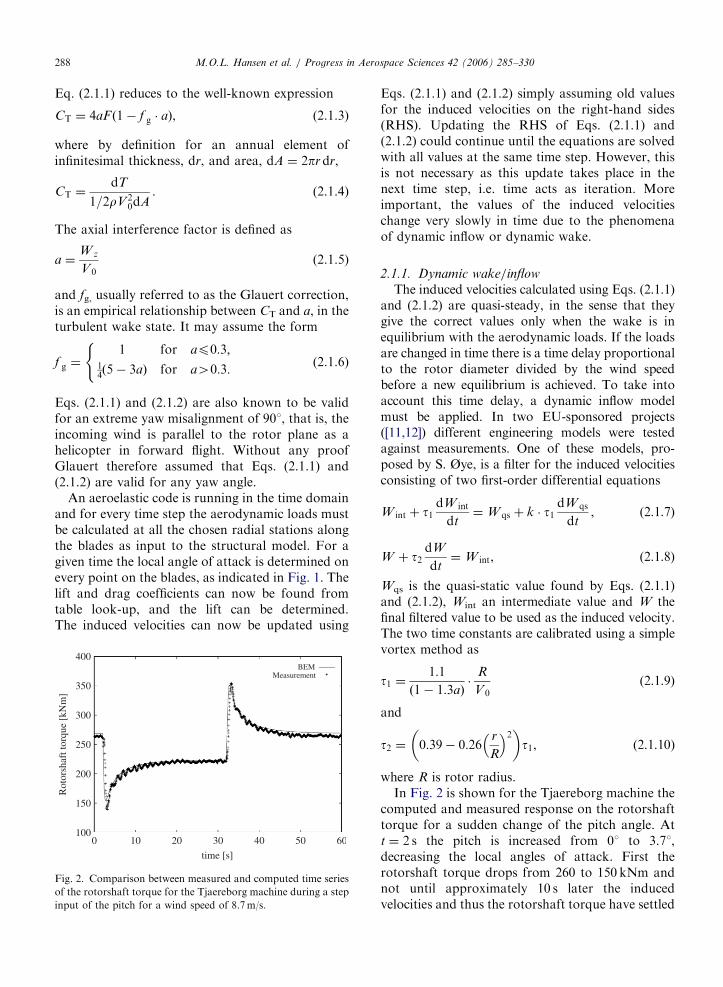
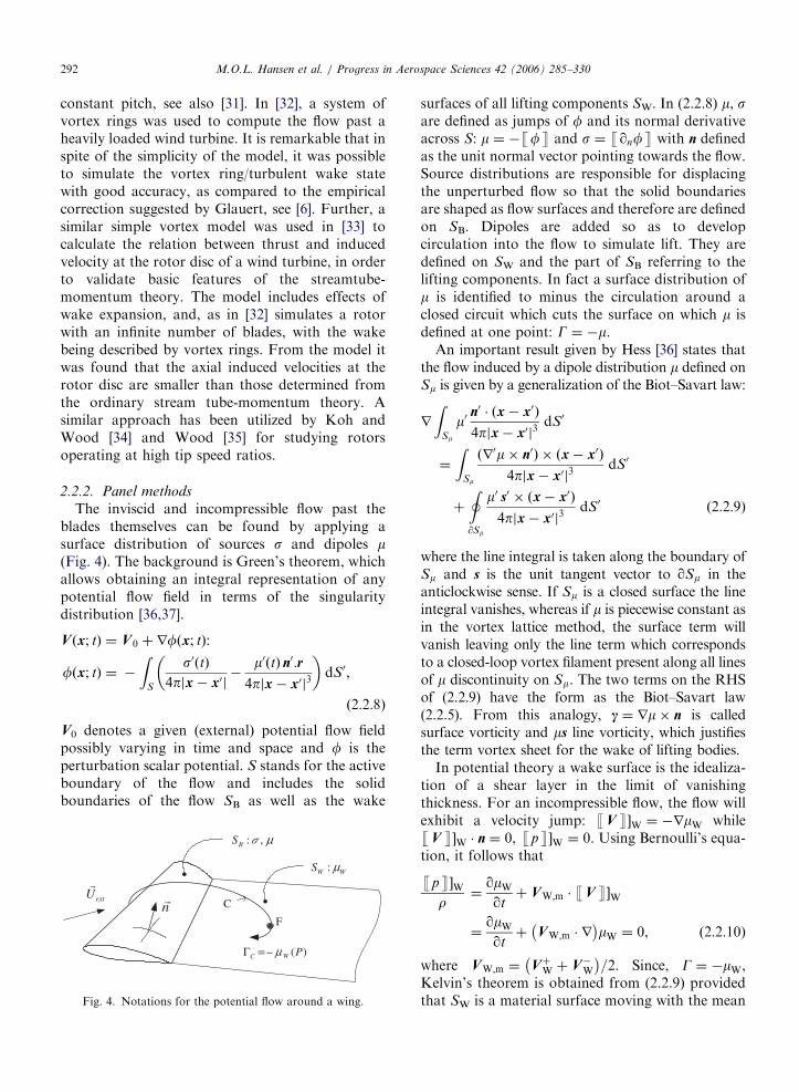

ARTICLE IN PRESS
emission line
Zero loading attrailing edge
Se
Se
W B
B
= minus Γ t
partΓ
partt= minus ⎜Γ
w
⎛
⎝
⎜⎛
⎝
Fig 6 The lifting-surface model
MOL Hansen et al Progress in Aerospace Sciences 42 (2006) 285ndash330 293
flow VWm Circulation will be materially conservedand therefore mW is identified with its value at t frac14 0For a lifting problem this means that mW is knownfrom the history of the wing loading Assuming thatSW starts at the trailing edge of the wing thegeneration of the wake can be viewed as acontinuous release of vorticity in the free flowThe streak line of a point along the trailing edge willreveal the history of the loading of the specific wingsection as indicated in Fig 7
The first model developed within the abovecontext is Prandtlrsquos lifting-line theory see eg [38]It concerns a lifting body of vanishing chord (or elselarge aspect ratio) and thickness (Fig 5) So s 0whereas SB becomes a line carrying the loading GethyTHORN(bound vorticity) which is the only unknown sincethe vorticity in the wake (trailing vorticity) is givenby yGethyTHORN In Prandtlrsquos original model GethyTHORN isdetermined from airfoil data as equation (221)Then as an introduction to lifting-surface theorybound vorticity was placed along the c4 line whilealong the 3c4 the non-penetration condition wasapplied in order to determine Gethy tTHORN The next stepwas to introduce the lifting body as a lifting surfaceThe most widely used model in this respect is thevortex-lattice model [39] It consisted of dividing SB
and SW into panels and defining on them piecewiseconstant m distributions (Fig 6) Then according to(229) the perturbation induced by the wing and itswake is generated by a set of closed-loop vortexfilaments each defined along the boundary of apanel The dipole intensities on the wing can bedetermined by the non-penetration condition at thepanel centres whereas along the trailing edge see(2210) m frac14 mW to ensure zero loading locally Inthe case of an unsteady flow the loading GB will
= minusparty Γδy
Γ(y)
w
yδ δΓ
Fig 5 The lifting-line model
change so that the vorticity shed in the wake willalso have a cross component qGB=qtdt asindicated in Fig 6
Having determined m it is possible to calculate theinduced velocity and thus the angle of attack andfinally the loads from an airfoil data table look-upAnother option frequently used in propeller appli-cations is to determine lift by integrating thepressure jump along the section Then by consider-ing that the lift force is perpendicular to the effectiveinflow direction the angle of attack is determined Inthis case the pressure jump is obtained directly fromBernoullirsquos equation over the section except at theleading edge where the geometrical singularity of ablade with no thickness makes it necessary toinclude the so-called suction force In propellerapplications where this concept was first introducedthe suction force is estimated by means of semi-empirical modelling [40] Whenever used in windenergy applications the suction force has beendetermined as rV Gdl where V G are the localvalues at the leading edge and dl represents thevector length along the leading edge line In generalthe two schemes give comparable results It isdifficult to clearly state which scheme is better touse since deviations appear as the angle of attackincreases so that a theoretical justification based onmatched asymptotic expansions is difficult Anotherpoint of concern regarding both lifting theories isthe detail in which the flow can be recorded Thefact that the flow geometry is approximate suggeststhat only at some distance from the solid boundarythe flow could be meaningful Finally for the samereason viscous corrections based on boundary layertheory cannot be applied
In order to overcome these difficulties the exactgeometry of the flow had to be included This wasdone by Hess who first introduced the panel method
ARTICLE IN PRESSMOL Hansen et al Progress in Aerospace Sciences 42 (2006) 285ndash330294
in its full form [41] Now the panel grid is defined onthe true solid boundary and a piecewise constantsource distribution is introduced which can bedetermined by the no-penetration boundary condi-tion In order to account for lift dipole distributionsare added Because there is no kinematic conditionto determine m Hess defined m to vary linearly alongthe contour of each section (Fig 7) meths y tTHORN frac14s Gethy tTHORN=LethyTHORN and used (2210) at the trailing edgeas an extra condition for determining Gethy tTHORN (Fig7) The resulting problem is non-linear and aniterative procedure must be used which penalizes thecomputational cost considerably as compared tothe lifting-surface model
An important aspect of potential flow modelsconcerns wake dynamics As discussed earlier thewake of a lifting body is a moving surface and SW
should be allowed to change in time Regarded as avortex sheet the evolution of SW in time will besubjected to convection and deformation Forexample in the case of the vortex lattice methodeach wake segment will conserve its intensity but itsvector length dl will satisfy the following equation
d
dtdl frac14 ethdl rTHORNV (2211)
As time evolves wake deformations will generatesingularities such as intense roll-up along the wakeextremities and crossings In fact at finite time theflow will blow-up In order to avoid blow-upcorrective actions must be taken If the simulationretains the connectivity of the wake surface thelines defining the wake must be smoothenedregularly during the run time Alternatively onecan apply remeshing which consists in dividing thewake vortex segments so that they do not exceed a
L
μ =minus ΓL
W E emission timeμ μ=
TE tμ TE t t
μminusΔ
2TE t tμ minus Δ 3TE t t
μminus Δ
wake surface
streak line
( )=B TEy t minusμΓ
emis
sion
line
s
T
Fig 7 The exact potential model of a wing
prescribed upper limit Both schemes howeverrequire substantial bookkeeping and quite intenseprocedures With panel methods this problembecomes more complicated because the wake willalso contain a surface vorticity term A completelydifferent approach is to discard wake connectivityRehbach [42] was the first to note that for anincompressible flow vorticity concentrations dO ofthe type o dD g dS and Gdl behave similarly Theirkinematic analogy was already discussed withreference to (229) Dynamically they all satisfythe same evolution equation
D
DtdO
qqt
dOthorn ethurTHORNdO frac14 ethdOrTHORNu (2212)
where D=Dt denotes the total or material timederivative So Rehbach integrated the wake vorti-city into point vortices which subsequently movedfreely as fluid particles carrying vorticity Thisprocedure provides substantial flexibility in theevolution of the wake He also introduced theconcept of modifying the kernel of the BiotndashSavartlaw in order to cancel the r2 singularity Thetheoretical justification of Rehbachrsquos method camelater on leading to the development of the vortex
blob method [43]In vortex models the wake structure can either be
prescribed or computed as a part of the overallsolution procedure In a prescribed vortex techni-que the position of the vortical elements is specifiedfrom measurements or semi-empirical rules Thismakes the technique fast to use on a computer butlimits its range of application to more or less well-known steady flow situations For unsteady flowsituations and complicated wake structures freewake analysis become necessary A free wakemethod is more straightforward to understand anduse as the vortex elements are allowed to convectand deform freely under the action of the velocityfield as in Eq (2212) The advantage of the methodlies in its ability to calculate general flow cases suchas yawed wake structures and dynamic inflow Thedisadvantage on the other hand is that the methodis far more computing expensive than the prescribedwake method since the BiotndashSavart law has to beevaluated for each time step taken Furthermorefree wake vortex methods tend to suffer fromstability problems owing to the intrinsic singularityin induced velocities that appears when vortexelements are approaching each other To a certainextent this problem can be remedied by introducinga vortex core model in which a cut-off parameter
ARTICLE IN PRESSMOL Hansen et al Progress in Aerospace Sciences 42 (2006) 285ndash330 295
models the inner viscous part of the vortex filamentIn recent years much effort in the development ofmodels for helicopter rotor flow fields have beendirected towards free-wake modelling using ad-vanced pseudo-implicit relaxation schemes in orderto improve numerical efficiency and accuracy eg[4445]
To analyse wakes of horizontal axis windturbines prescribed wake models have been em-ployed by eg [46ndash48] Free vortex modellingtechniques have been utilized by eg [4950]A special version of the free vortex wake methodsis the method described in [51] where the wakemodelling is taken care of by vortex particles orvortex blobs
Recently the model of [52] was employed in theNREL blind comparison exercise [137] and themain conclusion from this was that the quality ofthe input blade sectional aerodynamic data stillrepresents the most central issue to obtaining high-quality predictions Nevertheless it is worth noti-cing that by introducing relaxing techniques in thewake evolution [53] it is nowadays possible to run alarge number of revolutions which is of importancein aeroelasticity with reference to fatigue andstability analysis see later
An alternative to panel methods is offered by theBoundary Integral Equation Methods (BIEM) Byassuming stagnant flow inside the blade m frac14 fand s frac14 nf the resulting integral equation is onlyweakly singular and so less expensive Within thefield of wind turbine aerodynamics BIEMs havebeen applied by eg [54ndash56] up to now howeveronly in simple flow situations
Vortex methods have been applied on windturbine rotors particularly in order to better under-stand wake dynamics The next and quite challen-ging step is to upgrade potential flow methods so asto also include viscous effects Examples of applyingviscousndashinviscid coupling within the context of 3Dboundary layer theory can be found in [2657] Alsoattempts to include separation were made in [58]All these works however cannot be consideredconclusive There are several unresolved issues suchas convergence at the inboard region wheresignificant radial flow develops as a result ofsubstantial separation and the end conditions atthe tip The fact that current trends in wind turbinedesign indicate preference to pitch regulated ma-chines could increase the interest in flow modelsbased on inviscid considerations Finally anotherapplication of potential flow models is to use them
in order to obtain far field conditions for RANScomputations in view of reducing their computa-tional cost [59]
23 Generalized actuator disc models
The actuator disc model is probably the oldestanalytical tool for analysing rotor performance Inthis model the rotor is represented by a permeabledisc that allows the flow to pass through the rotorat the same time as it is subject to the influence ofthe surface forces The lsquoclassicalrsquo actuator discmodel is based on conservation of mass momentumand energy and constitutes the main ingredient inthe 1D momentum theory as originally formulatedby Rankine [60] and Froude [61] Combining it witha blade-element analysis we end up with thecelebrated Blade-Element Momentum Technique[6] In its general form however the actuator discmight as well be combined with the Euler or NSequations Thus as will be shown in the followingno physical restrictions have to be imposed on thekinematics of the flow
A pioneering work in analysing heavily loadedpropellers using a non-linear actuator disc model isfound in [62] Although no actual calculations werecarried out this work demonstrated the opportu-nities for employing the actuator disc on compli-cated configurations such as ducted propellers andpropellers with finite hubs Later improvementsespecially on the numerical treatment of theequations are due to [6364] Recently Conway[6566] has developed further the analytical treat-ment of the method Within wind turbine aero-dynamics [67] developed a semi-analytical actuatorcylinder model to describe the flow field about avertical-axis wind turbine A thorough review oflsquoclassicalrsquo actuator disc models for rotors in generaland for wind turbines in particular can be found inthe dissertation [68] Later developments of themethod have mainly been directed towards the useof the NS or Euler equations
In a numerical actuator disc model the NS (orEuler) equations are typically solved by a second-order accurate finite differencevolume scheme as ina usual CFD computation However the geometryof the blades and the viscous flow around the bladesare not resolved Instead the swept surface of therotor is replaced by surface forces that act upon theincoming flow This can either be implemented at arate corresponding to the period-averaged mechan-ical work that the rotor extracts from the flow or by
ARTICLE IN PRESSMOL Hansen et al Progress in Aerospace Sciences 42 (2006) 285ndash330296
using local instantaneous values of tabulated airfoildata
In the simple case of an actuator disc withconstant prescribed loading various fundamentalstudies can easily be carried out Comparisons withexperiments have demonstrated that the methodworks well for axisymmetric flow conditions andcan provide useful information regarding basicassumptions underlying the momentum approach[69ndash72] turbulent wake states occurring for heavilyloaded rotors [73] and rotors subject to coning[7475]
In Fig 8 an example of how various wake statescan be investigated by introducing a constantlyloaded actuator disc into the axisymmetric NSequations is shown By changing the thrust coeffi-cient all types of flow states can be simulatedranging from the wind turbine state through thechaotic wake state to the propeller state
The generalized actuator disc method resemblesthe BEM method in the sense that the aerodynamicforces has to be determined from measured airfoilcharacteristics corrected for 3D effects using ablade-element approach For airfoils subjected totemporal variations of the angle of attack thedynamic response of the aerodynamic forceschanges the static aerofoil data and dynamic stallmodels have to be included However correctionsfor 3D and unsteady effects are the same forgeneralized actuator disc models and the BEM
Fig 8 Various wake states computed by actuator disc model with pres
vortex ring state (d) hover state Reproduced from [7073]
model hence the description of how to deriveaerofoil data is the same as in Section 21
In helicopter aerodynamics combined NSactua-tor disc models have been applied by eg [76] whosolved the flow about a helicopter employing achimera grid technique in which the rotor wasmodelled as an actuator disk and [77] whomodelled a helicopter rotor using time-averagedmomentum source terms in the momentum equa-tions
Computations of wind turbines employing nu-merical actuator disc models in combination with ablade-element approach have been carried out ineg [69707879] in order to study unsteadyphenomena Wakes from coned rotors have beenstudied by Madsen and Rasmussen [74] Mikkelsenet al [75] and Masson et al [78] rotors operating inenclosures such as wind tunnels or solar chimneyswere computed by Hansen et al [80] Phillips andSchaffarczyk [81] and Mikkelsen and Soslashrensen [82]and approximate models for yaw have beenimplemented by Mikkelsen and Soslashrensen [83] andMasson et al [78] Finally techniques for employ-ing the actuator disc model to study the wakeinteraction in wind farms and the influence ofthermal stratification in the atmospheric boundarylayer have been devised by Masson [84] andAmmara et al [85]
The main limitation of the axisymmetric assump-tion is that the forces are distributed evenly along
cribed loading (a) wind turbine state (b) turbulent wake state (c)
ARTICLE IN PRESS
Fig 9 Actuator line computation showing vorticity contours
and part of computational mesh around a three-bladed rotor
Reproduced from [88]
Fig 10 Iso-surface of constant vorticity showing the formation
of tip and root vortices Reproduced from [89]
MOL Hansen et al Progress in Aerospace Sciences 42 (2006) 285ndash330 297
the actuator disc hence the influence of the blades istaken as an integrated quantity in the azimuthaldirection To overcome this limitation an ex-tended 3D actuator disc model has recently beendeveloped [86] The model combines a 3D NSsolver with a technique in which body forcesare distributed radially along each of the rotorblades Thus the kinematics of the wake isdetermined by a full 3D NS simulation whereasthe influence of the rotating blades on the flowfield is included using tabulated airfoil data torepresent the loading on each blade As in theaxisymmetric model airfoil data and subsequentloading are determined iteratively by computinglocal angles of attack from the movement ofthe blades and the local flow field The conceptenables one to study in detail the dynamics ofthe wake and the tip vortices and their influenceon the induced velocities in the rotor plane A modelfollowing the same idea has recently been sug-gested by Leclerc and Masson [87] A mainmotivation for developing such types of model isto be able to analyse and verify the validity ofthe basic assumptions that are employed in thesimpler more practical engineering models Re-views of the basic modelling of actuator discand actuator line models can be found in [88] thatalso includes various examples of computationsRecently another PhD dissertation [89] carried outa simulation employing more than four millionmesh points in order to study the structure of tipvortices In the following we will give someexamples of how the actuator discline techniquemay help in understanding basic features of windturbine flows
Computed iso-contours of vorticity for a three-bladed rotor with airfoil characteristics corres-ponding to the Tjaeligreborg wind turbine is shownin Fig 9 In Fig 10 a similar computationshows the formation of the trailing tip vortices Itis remarkable that the vortices are clearly visiblemore than 3 turns downstream A new andinteresting application of the actuator line modelis to study the interaction between two or moreturbines especially for simulating park effects InFig 11 the outcome of a computation in which theinteraction between two wind turbines is simulatedby replacing the two rotors by actuator lines withforces obtained from airfoil data is shown Pre-sently this technique is used to investigate the effectof large wind farms including many up- anddownstream wind turbines
24 Navierndash Stokes solvers
241 Introduction to computational rotor
aerodynamics
The first applications of CFD to wings and rotorconfigurations were studied back in the lateseventies and early eighties in connection withairplane wings and helicopter rotors [90ndash94] using
ARTICLE IN PRESS
Fig 11 Interaction of the wake between two partly aligned wind
turbines Reproduced from [88]
MOL Hansen et al Progress in Aerospace Sciences 42 (2006) 285ndash330298
potential flow solvers To overcome some of thelimitations of potential flow solvers a shift towardsunsteady Euler solvers were seen through theeighties [95ndash98] When computing power allowedthe solution of full Reynolds Averaged NS equa-tions the first helicopter rotor computations in-cluding viscous effects were published in the lateeighties and early nineties [99ndash102]
In the late nineties with the CFD solvers capableof handling viscous flow around rotors applicationto wind turbine rotors became of practical interest
The first full NS computations of rotor aero-dynamics was reported in the literature in the latenineties [103ndash107] The European effort to apply NSsolvers to rotor aerodynamics had been madepossible through a series of National and Europeanproject through the nineties The European projectsdealing with development and application of the NSmethod to wind turbine rotor flows was the Viscous
Effects on Wind turbine Blades (VISCWIND) from1995 to 1997 [108] Viscous and Aeroelastic effects on
Wind Turbine Blades (VISCEL) 1998 to 2000[109110] and Wind Turbine Blade Aerodynamics
and Aeroleasticity Closing Knowledge Gaps 2002 to2004 [111ndash115]
242 Approaches
As a consequence of the origin of most CFDrotor codes from the aerospace industry and relatedresearch many existing codes are solving thecompressible NS equations and are intended forhigh-speed aerodynamics in the subsonic andtransonic regime [116ndash120] For the helicopterapplications where compressibility plays an impor-
tant role this is the natural choice For wind turbineapplications however the choice is not as obviousone reason being the very low Mach numbers nearthe root of the rotor blades As the flow hereapproaches the incompressible limit Mach001 itis very difficult to solve the compressible flowequations One remedy to improve their capabilityis the so-called preconditioning that changes theeigenvalues of the system of the compressible flowequations by premultiplying the time derivatives bya matrix On the other hand the compressiblesolvers have many attractive features amongthese the ease of implementation of overlappingand sliding meshes application of high-order up-wind schemes and very well-developed solutionsmethods
Another very popular method especially in theUS is the Artificial Compressibility Method[121122] where an artificial sound speed is intro-duced to allow standard compressible solutionmethods and schemes to be applied for incompres-sible flows In case of transient computations sub-iterations are taken within each time step to enforceincompressibility [122] The method has severalattractive features Among these a similar ease ofimplementation of overlapping grids as the com-pressible codes Overlapping grids are a necessity tosolve rotorstator problems that are present whenthe rotor tower and nacelle are all included in thecomputations The main shortcoming of the methodmay be problems to enforce incompressibility intransient computations without the need for a hugeamount of sub-iterations and the problem ofdetermining the optimum artificial compressibilityparameter
Due to the low Mach number encountered inwind turbine aerodynamics an obvious choice isthus the incompressible NS equations Thesemethods are generally based on treating pressureas a primary variable [123ndash125] Extensions togeneral curvilinear coordinates can be made alongthe lines of [126] The method is not as easilyextended to overlapping grids as the compressibleand the artificial compressibility method due to theelliptical pressure correction equation But themethod is well suited for solving the nearlyincompressible problems often experienced in con-nection with wind energy In connection withsteady-state problems the method can be acceler-ated using local time stepping while the methodusing global time stepping still is well suited fortransient computations
ARTICLE IN PRESSMOL Hansen et al Progress in Aerospace Sciences 42 (2006) 285ndash330 299
243 Turbulence and transition
It is well known that the NS equations cannot bedirectly solved for any of the cases of practicalinterest to wind turbines and that some kind ofturbulence modelling are needed The standardapproach to derive turbulence models is by timeaveraging the NS equation resulting in the so-calledReynolds Averaged NS equations (RANS) Severaldifferent models have been used with good resultsfor wind turbine applications the most successfulones being the k-omega SST model of Menter [127]the SpalartndashAllmaras model [128] and the Bald-winndashBarth model [129] The BaldwinndashLomax [130]model often used in connection with helicopter andfix-wing applications are not very well suited forwind turbine applications where relatively highangles of attack are very common
Several studies performed for stall controlledwind turbines have shown that all RANS modelslack the capability to model the stalled flow regimeat high wind speeds One possible way around thisproblem the so-called Detached Eddy Simulation(DES) technique [131132] has shown some promis-ing results but still needs further validationAdditionally the DES technique is much morecomputationally expensive than the standardRANS approach as it needs much finer computa-tional meshes and the computations needs to becomputed with time accurate algorithms
From experiments it is known that laminarturbulent transition influences the flow over rotorblades for some cases It has been demonstratedfor 2D applications that transition models cangreatly improve the accuracy for cases wheretransition phenomena are important Even thoughnearly all rotor studies so far have been com-puted assuming fully turbulent conditions it isgenerally accepted that it is important to in-clude laminarturbulent transition to model thephysics as close as possible [133134] Predictingtransition in 3D is a much more complex task thandealing with 2D and 3D transition is an activeresearch field
244 Geometry and grid generation
To compute a rotor using CFD the first step is toobtain a digitized description of the blade geometryOften the blade descriptions are given as spanwisesectional information listing the airfoil section thetwist the thickness and the position with respect tothe blade axis Often the blades are highly twistedand with a large taper in the spanwise direction
Depending on the flow solver different ap-proaches to the mesh generation process existCartesian cut cells unstructured and structuredand combinations of these So far the majority offlow solvers applied to wind turbine research haveutilized structured grids with hexahedral cells Inconnection with structured grids there are severalissues that need to be decided upon Generally theproblem of making a high quality grid around amodern rotor cannot be handled by a single blockconfiguration but needs some kind of multi blockmesh These can either be conforming at the blockboundaries non-conforming or overlapping Theoverlapping grids gives the highest degrees offreedom followed by the non-conforming and theconforming grids Firstly the grid needs to accu-rately resolve the blade shape with good resolutionof the leading edge and tip region Secondly thegrids also need to resolve the regions around theblade with sufficient resolutions to capture the flowphysics As the Reynolds numbers are quite high1ndash6 million the cells near the rotor blades becomevery thin as the non-dimensional distance y+ mustbe approximately 1 to resolve the laminar sub-layerand have accurate solutions The mesh generationprocess calls for some degree of experience and gridrefinement studies to verify that the grid is sufficientto resolve the desired physics Also the grids need toextend far away from the rotor in the order ofseveral rotor diameters to avoid disturbing theinduced velocity field near the rotor blades Foraxial flow conditions the flow solvers often takeadvantage of the rotational periodicity of the rotorsolving only for a single blade using periodicconditions
Using an unstructured flow solver with tetrahe-dral cells the grid generation process is lesscumbersome But the problem of resolving verythin boundary layers using tetrahedral cells is wellknown and it may be necessary to combine thesolver with some kind of prismatic grids near theblade surface to avoid this problem The use ofunstructured flow solvers is not wide spread inconnection with wind turbine aerodynamics prob-ably because of the limited geometrical complexityand the strength of unstructured solvers mainlybeing their ability to cope with complex geometries
245 Numerical issues
The codes typically used for wind turbines are ofat least second-order accuracy in both time andspace often with an implicit time discretization
ARTICLE IN PRESSMOL Hansen et al Progress in Aerospace Sciences 42 (2006) 285ndash330300
scheme to loosen the time step restriction inherentto explicit methods Typically the viscous terms arediscretized with central differences while the con-vective terms are discretized with second- or third-order upwind schemes To solve routinely for 5ndash10million grid points the solvers are often available ina parallelized version that allows for execution onseveral CPUrsquos in parallel The rotating nature of theproblem requires the use of either a moving frameincluding the non-inertial acceleration terms or amoving mesh option where so-called mesh fluxesmust be included in the code For a good overviewof the numerical issues in connection with incom-pressible flow see [135]
246 Application of CFD to wind turbine
aerodynamics
The major part of wind turbine rotor computa-tions performed until now has been focused on zeroyaw rotor only configuration where the nacelle andtower have been neglected and the inflow to therotor has been assumed to be steady without shearThis is of course a great simplification but in manycases still a sufficiently good approximation Theeffect of the tower on the rotor on an upwindturbine is comparable to other unsteady effectssuch as incoming turbulence time variations of therotor and of the incoming flow A simulationworking with a full turbine geometry has been tried[106] This type of simulation is much moreexpensive and needs some kind of slidingover-lapping mesh to accommodate the movement of therotor with respect to the turbine tower and nacelleAdditionally the simulation needs to be timeaccurate and good resolution of the flow aroundthe tower is needed to capture the tower wake fardownstream of the turbine
700800900
10001100120013001400150016001700
6 8 10 12 14 16 18 20 22 24 26
Low
Spe
ed S
haft
Tor
que
[Nm
]
Wind Speed [m s]
MeasuredComputed
Fig 12 Comparison of computed and measured low-speed-shaft torque
flow conditions The 7 one standard deviation of the measurements is
One of the first real proofs that CFD for windturbine rotor applications can be useful came inconnection with the blind comparison organized bythe National Renewable Energy Laboratory inBoulder Colorado in December 2000 [136ndash138]Some of these results were later published in[139140] Here several wind turbine research groupswere asked to compute a series of differentoperational conditions for the NREL Phase-VIturbine corresponding to actual cases measured inthe NASA Ames 80 120 ft wind tunnel When theresults were made publicly available it proved thatone of the applied CFD codes were consistentlyreproducing the measured distribution of the aero-dynamic forces along the blade span even underhighly 3D and extreme stall conditions
The output extracted from typical CFD rotorcomputations are the low-speed shaft torque orpower production and root flap moments see Fig12 For modern full size commercial turbines thepower and root flap moment are typically the onlyavailable properties Besides the quantities normallymeasured the CFD simulations provide a hugeamount of detailed information that can be used toprovide more insight The data typically extractedare the spanwise distributions of force coefficientsFig 13 the limiting streamlines on the bladesurfaces Fig 14 and the sectional pressuredistributions along the blade span Fig 15 Forthe NREL Phase-VI turbine these detailed quan-tities can be compared to measurements but this isnot generally the case for commercially availableturbines
Another application of rotor CFD is the study ofdifferent aerodynamic details of the rotor such asthe blade tips the design of the root section etcHere the CFD technique can be used to supply
1000
1500
2000
2500
3000
3500
4000
4500
5000
6 8 10 12 14 16 18 20 22 24 26
Roo
t Fla
p M
omen
t [N
m]
Wind Speed [ms]
MeasuredComputed
and root flap moment for the NREL Phase-VI rotor during axial
indicated around the measured values
ARTICLE IN PRESS
0
05
1
15
2
25
3
02 03 04 05 06 07 08 09 1
CN
rR
MeasuredComputed
-008
-006
-004
-002
0
002
004
02 03 04 05 06 07 08 09 1
CT
rR
MeasuredComputed
Fig 13 Spanwise normal and tangential force coefficients for run S20000000 of the NRELNASA Ames measurements corresponding
to a wind speed of 20ms
NREL PHASE-6 W=10 [m s] Limiting StreamlinesRISOE EllipSys 3D Computation
Fig 14 Limiting streamlines on the surface of the NREL Phase-
VI rotor for the 10ms axial case The picture shows a sudden
leading edge separation around rR frac14 047
-15
-1
-05
0
05
1
15
2
25
3
0 02 04 06 08 1
-Cp
X Chord
rR=063
Fig 15 Comparison of the measured and computed pressure
distribution at the rR frac14 063 section of the NREL Phase-VI
blade the measurements are shown as circles while the
computations are shown with lines
MOL Hansen et al Progress in Aerospace Sciences 42 (2006) 285ndash330 301
information that the engineering methods are notcapable of providing
With the increase in computational power it istoday both possible and affordable to do yawcomputations using CFD [133141ndash143] In contrastto the axial flow cases the total rotor must be
modelled in yaw simulations thereby increasing thenumber of mesh points typically by a factor ofthree Additionally the azimuthally variation in-herent in yaw simulations dictates a time accuratesimulation as no steady state solution can existthereby increasing the computing time severelyTypically a yaw computation will be 10ndash20 timesmore expensive compared to steady state axial flowcomputations Fig 16 shows the normal andtangential force at the rR frac14 30 radius duringone revolution at 601 yaw operation
The release of the measurements on the NRELPhase-VI rotor has heavily influenced the CFDactivities dealing with wind turbine rotor aerody-namics This unique data set with several well-documented cases has given a new possibility to testdetails of state of the art CFD codes In the yearssince the release of the measurements nearly half ofall published CFD studies of wind turbine rotorsdeals with these measurements Besides the refer-ences mentioned other places in this paper thefollowing studies use the NRELNASA Amesmeasurements [144ndash147]
Recently DES simulations of rotors at realisticoperational conditions have been attempted [148]Again the NREL Phase-VI rotor was used to verifythe model The reason for this choice is besides theavailability of detailed measurements the fact thatthe rotor has a limited aspect ratio hence makingthe DES computations more affordable with respectto the number of grid cells The mesh for thissimulation consists of 15 million cells compared toaround 2 million cells for a standard RANS rotorcomputation The fact that DES computations mustbe performed using time accurate computationsmakes these types of simulations 20ndash40 times more
ARTICLE IN PRESS
-2
0
2
4
6
8
10
12
0 50 100 150 200 250 300 350
CN
Azimuth Angle [deg]
S1500600 r R=030
MeasurementsComputed
MeasurementsComputed
-04
-02
0
02
04
06
08
1
0 50 100 150 200 250 300 350
CT
Azimuth Angle [deg]
S1500600 rR=030
Fig 16 Azimuth variation of normal and tangential force coefficient for the NREL Phase-VI turbine at the rR frac14 04 section during a
601 yaw error at 15ms wind speed
MOL Hansen et al Progress in Aerospace Sciences 42 (2006) 285ndash330302
expensive than standard steady-state rotor compu-tations For modern-type rotors with large aspectratios the cell count would be even higher and thecomputations even more expensive For the NRELPhase-VI rotor the improvement using the DEStechnique is very limited but for other rotors wherethe RANS equations do not perform as well DESmay provide much more improvement The use ofpure Large Eddy Simulation has been demon-strated in [149] where a computational grid of 300million points is used to compute the initialtransient of the development of a tip vortex
247 Future
Today NS solvers are an important tool foranalysing different wind turbine rotor configura-tions and are used routinely along with measure-ments and other computational tools fordevelopment and investigation of wind turbinesNS solvers are especially well suited for detailedinvestigation of phenomena that cannot directly beaccessed by simpler and less computationallyexpensive methods Additionally NS methods canbe used as a supplement to measurements wherethey can be used both in the planning phase and tohave a better interpretation of the actual physics inconnection with the analysis of measurements
Finally one of the latest trends is to couple NSsolvers to structural codes to perform full elasticcomputations of wind turbine rotors
3 Structural modelling of a wind turbine
The main purpose of a structural model of a windturbine is to be able to determine the temporalvariation of the material loads in the variouscomponents This is accomplished by calculating
the dynamic response of the entire constructionsubject to the time-dependent load using an aero-dynamic model such as the BEM method Foroffshore wind turbines also wave loads and perhapsice loads on the bottom of the tower must beestimated Two different and frequently usedapproaches to set up a dynamic structural modelfor a wind turbine are described in the nextsubsections
31 Principle of virtual work and use of modal shape
functions
The principle of virtual work is a method to setup the correct mass matrix M stiffness matrix Kand damping matrix C for a discretized mechanicalsystem as
M euroxthorn C _xthorn Kx frac14 Fg (311)
where Fg denotes the generalized force vectorassociated with the external loads p Eq (311) isof course nothing but Newtonrsquos second law assum-ing linear stiffness and damping and the method ofvirtual work is nothing but a method that helpssetting this up for a multibody system and that isespecially suited for a chain system Knowing theloads and appropriate conditions for the velocitiesand the deformations Eq (311) can be solved forthe accelerations wherefrom the velocities anddeformations can be determined for the next timestep The number of elements in x is called thenumber of DOF and the higher this number themore computational time is needed in each time stepto solve the matrix system Use of modal shapefunctions is a tool to reduce the number of DOFand thus reduce the size of the matrices to make thecomputations faster per time step A deflection
ARTICLE IN PRESSMOL Hansen et al Progress in Aerospace Sciences 42 (2006) 285ndash330 303
shape is here described as a linear combination of afew but physical realistic basis functions which areoften the deflection shapes corresponding to thelowest eigenfrequencies (eigenmodes) For a windturbine such an approach is suited to describe thedeflection of the tower and the rotor blades and theassumption is that the combination of the PowerSpectral Density of the loads and the damping ofthe system do not excite the eigenmodes associatedwith higher frequencies In the commercially avail-able and widely used aeroelastic simulation toolFLEX see eg [150] only the first 3 or 4 (2 flapwiseand 1 or 2 edgewise) eigenmodes are used for theblades Results from this model are generally ingood agreement with measurements indicating thevalidity of the underlying assumption First one hasto decide on the DOF necessary to describe arealistic deformation of a wind turbine For instancein FLEX4 17ndash20 DOFs are used for a three bladedwind turbine with 3ndash4 DOFs per blade as describedabove 4 DOFs for the deformation of the shaft (1for torsion 2 for the hinges just before the firstbearing with associated angular stiffness to describebending and 1 for pure rotation) 1 DOF todescribe the tilt stiffness of the nacelle and finally3 DOFs for the tower (1 for torsion 1 for the firsteigenmode in the direction of the rotor normal and1 in the lateral direction)
The method of virtual work will only be brieflydescribed For a more rigorous explanation of themethod the reader is referred to textbooks ondynamics of structures The values in the vectordescribing the deformation of the construction xiare denoted the general coordinates To eachgeneralized coordinate is associated a deflectionshape ui that describes the deformation of theconstruction when only xi is different from zero andtypically has a unit value The element i in thegeneralized force corresponding to a small displace-ment in DOF number i dxi is calculated such thatthe work done by the generalized force equals thework done on the construction by the external loadson the associated deflection shape
Fgidxi frac14
ZS
p uidS (312)
where S denotes the entire system Please note thatthe generalized force can be a moment and that thedisplacement can be angular All loads must beincluded ie also gravity and inertial loads such asCoriolis centrifugal and gyroscopic loads The non-linear centrifugal stiffening can be modelled as
equivalent loads calculated from the local centrifu-gal force and the actual deflection shape as shown in[151] The elements in the mass matrix mij can beevaluated as the generalized force from the inertialoads from an unit acceleration of DOF j for a unitdisplacement of DOF i The elements in the stiffnessmatrix kij correspond to the generalized force froman external force field which keeps the system inequilibrium for a unit displacement in DOF j andwhich then is displaced xi frac14 dij where dij isKroneckers delta The elements in the dampingmatrix can be found similarly For a chain systemthe method of virtual work as described herenormally gives a full mass matrix and diagonalmatrices for the stiffness and damping For oneblade rigidly clamped at the root (cantilever beam)it is relatively easy to estimate the lowest eigen-modes (first flapwise u1f(x) first edgewise u1e(x) andsecond flapwise u2f(x)) eg using an iterative methodas described in [151] The eigenmodes are normallydescribed in a coordinate system aligned with the tipchord as eg shown in Fig 1 It is practical tonormalize the deflection shapes so that the tipdeflection is unity It is now assumed that anydeflection can be described as a linear combinationof these modes as
uethxTHORN frac14 x1u1f ethxTHORN thorn x2u
1eethxTHORN thorn x3u2f ethxTHORN (313)
The velocity and accelerations can be calculatedrespectively as
_uethxTHORN frac14 _x1u1f ethxTHORN thorn _x2u
1eethxTHORN thorn _x3u2f ethxTHORN (314)
and
eurouethxTHORN frac14 eurox1u1f ethxTHORN thorn eurox2u
1eethxTHORN thorn eurox3u2f ethxTHORN (315)
The advantage of the method using generalizedcoordinates and modal shape functions is that thenumber of DOF in the dynamic system can bereduced to a relatively small number Further somehigh eigenfrequencies are filtered away which isbeneficial for the allowable time step when comput-ing deformations xnthorn1
i and velocities _xnthorn1i at time
t frac14 (n+1)Dt from deformations xni velocities _xn
i and accelerations euroxn
i at time t frac14 nDt A goodchoice for the time integration scheme is theRungendashKuttandashNystrom method which requiresfor stability reasons that the time step shouldresolve the highest eigenfrequency with 4 pointsbut for accuracy reasons 10 points is preferredBy reducing the highest eigenfrequency using amodal description of eg the blades not only
ARTICLE IN PRESSMOL Hansen et al Progress in Aerospace Sciences 42 (2006) 285ndash330304
reduces the number of DOFs but also larger timesteps can be taken
32 FEM modelling of wind turbine components
applying non-linear beam theory
Even though modal analysis offers a computa-tionally effective way to analyse wind turbinedynamics most of the recently developed aeroelasticcodes use a full FEM approach [152] which allowsa more complex deformation state of the windturbine The main features of such modellingprocedures together with some aspects of non-linearbeam theory are discussed in the present section
The structural modelling of wind turbines isbased on beam theory For a 1D structure (beam)subjected to bending in two directions torsion andaxial tension the formulation of the problemconsists of two parts (a) the elastic model whichreduces the 3D structure of each component into a1D structure concentrated along the elastic axis ofthe beam and (b) the derivation of the dynamicequations In classical beam theory (first order) thedeformed position r of any point initially at x0 frac14ethx y zTHORNT (Fig 17) can be described by the displace-ment vector u frac14 fu vw ygT consisted of the two
Undeformed geometry
x
z
u
wr
zF +
Mx
Fx
Mz
FzMy
Fy
x
z
(a)
a
b
Fig 17 Kinematics and dynam
bending displacements u w the torsion angle y andthe tension v
r frac14 n0 thorn S0 uthorn S1 yu
S0 frac14
1 0 0 z
0 1 0 0
0 0 1 x
264
375
S1 frac14
0 0 0 0
x 0 z 0
0 0 0 0
264
375
(321)
Using Hookersquos law and assuming that shear stressesdo not produce net torsion the sectional elasticloads can be derived
Fy frac14 ethEATHORNqyv ethEAxTHORNq2yyu ethEAzTHORNq2yyw
My frac14 ethGItTHORNqyy
Mx frac14 ethEIxzTHORNq2yyuthorn ethEIxxTHORNq
2yyw ethEAzTHORNqyv
Mz frac14 ethEIzzTHORNq2yyu ethEIxzTHORNq
2yywthorn ethEAxTHORNqyv
eth322THORN
where the terms in parentheses denote the averagedsectional properties of the structure By consideringthe balance of loads and moments on of a beam
Deformed geometrydy
y
A
u+du
w+dwDeformed elastic axis
M + dMz
z
z
M + dMyy
M + dMxx
dF
yyF + dF
xxF + dFdr
ra
δPy
A(b)
ics of a beam structure
ARTICLE IN PRESS
x
z
yu
w
vO
Orsquoz
xz
xu
w θtθ
ζ
ξ
ξ
θθ
θ +ˆ
Fig 18 Beam co-ordinate system definition
MOL Hansen et al Progress in Aerospace Sciences 42 (2006) 285ndash330 305
element of length dy the beam equations arederivedZ
A
eurordm
dy frac14 dFthorn
ZA
g dm
dythorn dpdy
(323)
ZA
r0 eurordm
dy frac14 dMthorn dr ethFthorn dFTHORN
thorn
ZA
r0 gdm
dythorn ra dpdy eth324THORN
where m denotes the mass per unit length dF dMare the net elastic loads on dy g is the accelerationof gravity and dp the sectional aerodynamic loadsexerted at the aerodynamic centre ra frac14 ethxa 0 zaTHORNwhile
r0 frac14 fduthorn xthorn zy dvthorn dydwthorn z xygT
ffi fxthorn zy dy z xygT
In view of a more systematic and general frameworkfor formulating dynamic equations Hamiltonrsquosprinciple has been also used [153154]
By introducing (322) into (323) and (324) thebeam dynamic equations are obtainedZ
A
ethS0THORNT euror dm qy
ZA
ethS1THORNT euror dm frac14 qyfrac12K11 qyu
thorn q2yyfrac12K22 q2yyu thorn qyfrac12K12 q
2yyu
thorn q2yyfrac12K21 qyu thorn
ZA
ethS0THORNT g dmthorn Sa dP
eth325THORN
K11 frac14
Fy 0 0 0
0 EA 0 0
0 0 Fy 0
0 0 0 GIt
2666664
3777775
K22 frac14
EIzz 0 EIxz 0
0 0 0 0
EIxz 0 EIxx 0
0 0 0 0
2666664
3777775
Sa frac14
1 0 0
0 1 0
0 0 1
za 0 xa
2666664
3777775
K12 frac14
0 0 0 0
EAx 0 EAz 0
0 0 0 0
0 0 0 0
2666664
3777775
K21 frac14
0 EAx 0 0
0 0 0 0
0 EAz 0 0
0 0 0 0
2666664
3777775
In case of flexible blades if large deformations areexpected as in the case of helicopter blades second-order non-linear beam theory is to be used Therelevant developments originate from the work in[154] The beam axis again lies along the y-axis butin the undeformed state of the beam while x and z
denote the two bending directions of the beam Atits deformed state a local co-ordinate system O0xZzis introduced which follows the pre-twist of thebeam so that x and z coincide with the localstructural principle axes of the cross section(Fig 18)
Then (321) becomes
r frac14
u
ythorn v
w
8gtltgt
9gt=gtthorn E
x
lyy
z
8gtltgt
9gt=gt (326)
where l denotes the warping function of the crosssection and E is the transformation matrix betweenOxyz and O0xZz In [154] E is given in terms of theelastic displacements up to second order Next thestrain tensor ij defined through (326) is introducedin Hookersquos law in order to define the strainndashdispla-cements relations which are used in the derivationof the resulting sectional elastic loads as in (322)Because they are derived in the O0xZz system beforeintroducing them in (323) and (324) they aretransformed into the Oxyz system using the
ARTICLE IN PRESS
ρk
rGk
OG O
xG x
zG z
yG
y y
z
x
O
x
y
z
O
Fig 19 Multi-body representation of a wind turbine
MOL Hansen et al Progress in Aerospace Sciences 42 (2006) 285ndash330306
transformation matrix E The final expressions arequite lengthy and the reader is referred to [154] It isnoted that compared to the classical beam modelsecond-order theory will produce fully completestiffness matrices containing many non-linear termsThe above non-linear beam model is a specificexample amongst several models of varying com-plexity which have been gradually developed start-ing from the Timoshenko beam theory byeliminating the ad hoc simplifying assumptions ofthe original model [155ndash158]
Regarding wind turbines almost all structuralmodels are based on classical beam theory[150153159ndash162] This is partially due to the factthat wind turbine components are far more rigidcompared to helicopter blades for which non-lineartheory has been developed Furthermore most of thedifficulties in analysing wind turbine systems aregenerated by the aerodynamics and in particular theonset of stall which is certainly less pronounced onhelicopter rotors Current designs are quite stiff sothat non-linear beam modelling is not expected tochange drastically the quality of predictions besidesproviding a sound basis for including the geometricalnon-linearities [163] However if wind turbinesbecome more flexible it could become necessary toadopt such kind of structural modelling
Regardless the details the beam equations arefourth order with respect to bending and secondorder with respect to tension and torsion So for aFE approximation of the equations C1 shapefunctions are used for uw and C0 for v and y Atthe element level uw are approximated with third-order polynomials and the DOFs are the values andspace derivatives at the end nodes while v and y areapproximated with first-order polynomials and theDOFs again at the end nodes In some models andcertainly when the second-order beam theory isapplied second- and third-order polynomials areused respectively for v and y In this case the mid-point as well the points at 13 and 23 interior pointsare used as nodes So within an element lsquolsquoersquorsquo
ueethy tTHORN frac14 NeethyTHORN ueethtTHORN (327)
where NeethyTHORN is the matrix containing the shapefunctions and ueethtTHORN the vector of the DOFs at thenodes of the elements [164] As in Section 31concerning the principle of virtual work which inthe FEM terminology is the Galerkin formulationof the problem is used to generate the discreteequations With reference to (325) taken symboli-cally as Zethu _u eurouTHORN frac14 0 for any admissible virtual
displacement field du we require that
Z L
0
duT Zethu _u eurouTHORNdy
X
e
Z Le
0
duTe Zethue _ue euroueTHORNdy frac14 0 8du eth328THORN
Because dueethy tTHORN frac14 NeethyTHORN dueethtTHORN it follows that
Xe
Z Le
0
NeT ZethNeueNe _ueN
e euroueTHORNdy frac14 0 (329)
which is a set of second-order ordinary equations intime with respect to ueethtTHORN Although Z can containnon-linear terms it can always be written in theusual form
MethuTHORN eurouthorn Cethu
THORN _uthorn Kethu
THORN u frac14 Qethu
THORN (3210)
where the mass damping and stiffness matrices aswell as the generalized loads in the RHS in generalwill depend on the displacement field and its timeand space derivatives (noted by a tilde)
ARTICLE IN PRESS
y
O
q8 q9 q10 q11q12 q13
yG y
z
x
O
x
y
z
OG O
xG x
zG z
q1 q2 q3 q4q5 q6
q7
q14
Fig 20 A typical definition of the q DOF on a HAWT
MOL Hansen et al Progress in Aerospace Sciences 42 (2006) 285ndash330 307
The main components of a wind turbine are theblades the drive-train and the tower (Fig 19) Theyare all modelled as beam structures and typically thestructural properties are assumed for each compo-nent to continuously vary along the correspondingelastic axis However localized properties can beadded in the form of concentrated masses dampersor springs The gearbox (if present) the generatorthe hub are usually added in this way Otherexamples are the flexibility or damping character-istics of the yaw bearing or the pitch mechanismThe involvement of different body motions for eachcomponent in combination with the connectionswhere loads and displacements are communicatedfrom one component to the other calls for a globalformulation of the dynamic problem To this endmost works adopt a multi-body approach [165]which consists of considering each componentseparately subjected to appropriate boundary con-ditions which fit the different components into thecomplete configuration In such an approach theelastic DOF of each component are defined as localelastic displacements to which rigid body motionsare added through the kinematic boundary condi-tions see eg [161166167] for a more generaldiscussion It is also possible to introduce the globaldisplacements and rotations at each node instead ofthe local ones [153] allowing a unified description ofthe complete configuration In this case howeverthe non-linearities of the connections are introducedimplicitly and therefore linearization can only beperformed globally which is not always desirable
In multi-body modelling each component k isassigned a local coordinate system Oxyz with itsundeformed elastic axis along the y-axis Then theposition of a point with respect to the fixed systemrGk can be expressed with respect to its localposition rk (defined as in (321)) as follows
rGk frac14 qk thorn Ak rk (3211)
where qk denotes the position of the origin of thelocal system with respect to the fixed system and Ak
denotes the local to global transformation matrixThe exact form of qk and Ak depends on thekinematic conditions introduced when joining (con-necting) the various components (ie blades-to-hubor drive-train-to-tower) Depending on the type ofconnection common global displacements androtations are assigned for the restricted DOF whichare identified to either an existing elastic DOF (shaftbending at the hub) or a rigid body motion (bladepitch) The component contributing the kinematics
will in response receive from the rest of theconnected components their internal (or reaction)loads This operation involves co-ordinate systemtransformations between the components The setof kinematical DOF involved in the definition of qk
and Ak for all components is denoted collectively asq So qk frac14 qk(q t) and Ak frac14 Ak(q t) qk is defined asa mixed series of translations and rotations whereasAk is defined solely as a sequence of rotations Atypical example is shown in Fig 20 where q1ndashq6 arethe elastic DOF at the top of the tower q8ndashq13 arethe elastic DOF of the drive train at the hub and q7and q14 are the yaw angle and the pitch of the bladerespectively By introducing (3211) into (325) thecentrifugal and Coriolis terms of the inertia loadsappear as a result of the time derivatives of Ak whilein the Hamiltonrsquos principle approach they areproduced automatically
By combining the equations of all componentsthe complete system of the dynamic equations forthe wind turbine is obtained in the form of (3210)with respect to an extended vector of DOFuext frac14 u q
By construction qk and Ak will depend
on unknown DOF while at the same time theycorrelate the state of the components in contact sothe terms they generate are non-linear with respectto the unknown DOF uk and q Linearization in thiscase is a tedious procedure which must be donecarefully and systematically Fortunately softwareusing symbolic mathematics such as Mathematica
ARTICLE IN PRESSMOL Hansen et al Progress in Aerospace Sciences 42 (2006) 285ndash330308
are available which are strongly recommended Theprocedure is based on Taylorrsquos expansions of allvariables and retaining of first-order terms Alter-natively the extended version of (3210) can besolved directly through an iterative procedure ineach time step which can use the linearized solutionas a starting predictor
4 Problems and solutions in wind turbine
aeroelasticity
In the following section the use of aeroelasticcodes on wind turbine constructions includingstability studies will be illuminated mainly throughexamples
41 Aeroelastic stability
Wind turbines suffer from low structural damp-ing which can become critical under certain opera-tional conditions Most problems appear on theblades that receive almost 100 of the loading Inparticular the onset of stall plays a decisive role notonly on stall-regulated machines but also on pitch-regulated ones around rated conditions On theother hand the blades are made of compositematerials for which the knowledge on damping issubstantially inferior compared to steel or concreteconstructions The damping of composite structuresdepends on the ambient temperature So dependingon the season or the time during the day thestructural damping of the blades can decreasesubstantially Furthermore aging always degradesthe damping of composite structures There is adefinite need to increase structural damping andsignificant effort has been put recently on itsmodelling in composite structures as well as in theirappropriate design This is one direction of researchregarding the improvement of the stability char-acteristics of modern wind turbines see [168] for areview of the current developments Damping isrequired to suppress the onset of vibrationsgenerated by the unsteady aerodynamic loads thatinteract with the wind turbine structure First theaeroelastic modelling of wind turbines is consideredand then on this basis the aeroelastic stabilityproblem is formulated and the relevant availablemethods are reviewed
Aerodynamic modelling involves the calculationof the aerodynamic loads that also depend on thedynamics of the system The flap and lag vibrationsare interpreted by the incoming flow as a change in
the effective angle of attack indicating strongaeroelastic coupling All the currently availableaeroelastic tools for wind turbines use 2D dynamicairfoil data models such as the BeddoesndashLeishmannor the ONERA model They provide aerodynamiccoefficients as functions of the aerodynamic statevariables that satisfy appropriate dynamic equa-tions [17169] In either model the equations are 2Dand so they are applied on a strip-by-strip basismeaning that there is no interaction in the radialdirection This fits well with BEM modelling of theoverall aerodynamic analysis In fact the followingpresentation is referred to the BEM context sincemost existing stability models are based on it If apotential flow model is applied then the attachedpart of lift can be associated to potential lift whilethe rest is simply added [163] If the potential flowmodel is enhanced with a separation model thereshould be correlation on both aspects [58] How-ever the latter has not been applied yet inaeroelastic computations
By considering a blade section at a radial positionas shown in Fig 1 the local aerodynamic loadsacting on this section of the blade can be written asfollows since the lift is perpendicular and the dragparallel to the relative wind
py frac14 L sin fD cos f
pz frac14 L cos fthornD sin f
My frac14M eth411THORN
where L D are the lift and drag forces M is thepitching moment f is the local flow angle withrespect to the rotor plane Once the induced velocityhas been determined the local effective incidence aand relative flow velocity can be calculated as shownin Section 21 They will depend on the elasticdeformations and the velocities the rigid bodymotions and if appropriate orientation changes asin pitch and yaw variations In order to obtain aunified description of the coupled aeroelasticproblem a so-called aeroelastic finite element isdefined [170] which in addition to the elastic DOFthe aerodynamic state variables added For examplein the ONERA model there will be in total eightadditional DOF Because the dynamic equations forthe aerodynamic state variables only can be firstorder in time in order to produce a consistentcoupled system they can be differentiated as in[171] Therefore they can be assembled togetherwith the dynamic equations in the form of (3210)where the vector of the unknowns is further
ARTICLE IN PRESSMOL Hansen et al Progress in Aerospace Sciences 42 (2006) 285ndash330 309
extended to include the additional aerodynamicDOF Another approach used in [172] is tointroduce the modal expansion of the structuralDOF at stand still which better conditions thecoupled system
On the above basis it is possible to formulate theaeroelastic stability problem for wind turbinesWithin the context of linear theory stabilityboundaries are obtained by examining the evo-lution of small perturbations with respect to asteady state or a periodic solution acting asreference To this end the original equations arelinearized with respect to the reference state andthe resulting system solved with respect to thefluctuations
Methuref THORN eurouthorn Cethuref THORN _uthorn Kethuref THORN u frac14 Q (412)
where M C and K depend only on the referencesolution If the matrices do not depend on time(412) is reformulated into a first-order system
_y frac14 D ythorn b y frac14 u _un oT
(413)
The eigenvalue analysis of D provides the eigen-frequencies and damping of the system [173] This ispossible when the reference state corresponds to asteady solution as in the case of an isolated bladeHowever when analysing the complete windturbine configuration due to the rotation of theblades the reference state should correspond to aperiodic equilibrium state with reference to the rotorspeed which is assumed constant In this case thecorresponding theoretical framework is Floquetrsquostheory which for a large system is computationallyheavy [174] If the blades are identical and thenumber of blades NX3 which is the most frequentcase it is possible by means of multi-bladetransformation to eliminate the periodic coefficientsin the coefficients of (412) and therefore be ableto still use eigenvalue analysis [175] In this contextthe non-linear equations of the system are inte-grated in time until such a periodic state is attainedIn the case of an unstable situation because thetime domain response will contain significantcomponents in all of the basic eigenfrequencies ofthe system the reference state is obtained bytruncating the response so as to retain only its 1and Nrev components To this end all DOF in therotating system qm m frac14 1 NX3 are reformedqm frac14 q0 thorn qc cos cm thorn qs sin cm where cm frac14 Otthorn
eth2p=NTHORNethm 1THORN is the corresponding azimuth loca-tion Next the equations for the blade DOFs are
rearranged by applying the operators eth1=NTHORNPN
mfrac141
eth THORN eth2=NTHORNPN
mfrac141eth THORN cos cm and eth2=NTHORNPN
mfrac141eth THORN
sin cm This is performed after the periodic solutionhas been obtained over one period of rotation Theresulting equations will be in the non-rotating frameand contain only higher harmonics (3rev andhigher) By averaging over one period the finalconstant coefficient system is obtained in the formof (413) For the blades y will contain thecorresponding q0 qc and qs DOF and their timederivatives for both the purely structural and theaerodynamic DOF [171] In the above approach it isworth noticing that the averaging procedure willforce the reference state to appear in the equationsThis is an important aspect when dealing with non-linear systems
Stability of wind turbines has been consideredsystematically in Europe in the late 1990s [176] whiletoday there is an on-going activity under the EUfunded project STABCON Several linear stabilitytools have been produced along the lines describedabove and good correlation has been obtainedamongst the different codes see [177] and thereferences cited Inevitably linear theory is approx-imate so the results it produces are subject to crosschecking Clearly flutter measurements are difficultto obtain because of the involved risk therefore it isindispensable to rely on theoretical developmentswhich will be discussed in the next section
42 Aeroelastic coupling linear vs non-linear
formulations
Linearization of the aeroelastic equations cer-tainly offers computational efficiency However it isnot always appropriate For the structure lineartheory requires that the deformations and displace-ments are small an assumption not always validFor the aerodynamics and its coupling with thestructure linearization will suppress some depen-dencies involved in (411) and therefore influencethe estimation of the aerodynamic damping In thisconnection the use of semi-empirical unsteadyaerodynamic models introduces still unresolveduncertainties Furthermore there are cases in whichthe multi-blade transformation is not applicable egwhen blades are non-identical or when the rota-tional speed varies
Retaining fully the non-linearities of the aero-elastic problem has the following consequences thestructure is considered at its deformed state thecoupling conditions among the components are
ARTICLE IN PRESSMOL Hansen et al Progress in Aerospace Sciences 42 (2006) 285ndash330310
taken in their full form and the aerodynamicequations are not simplified The last point isimportant with respect to the best possible estima-tion of the aerodynamic damping within themargins offered by the semi-empirical models usedin the currently available aeroelastic tools In thisrespect multi-body analysis which has beenadopted in most of the existing stability tools[161178ndash181] offers this option by constructionprovided that the structural model considers theconstruction at its deformed state and the codetakes this into account in the definition of the localaerodynamics
Under such conditions the information of thestability characteristics of the wind turbine arecontained in the time signals of the loads calculatedthrough a non-linear time domain simulation Thereexist two types of methodologies for retrieving thisinformation the one is based on the work-basedapproach [176] while the other is using signal-processing techniques In the work-based methodany mode shape is excited and loads are recordeduntil a steady periodic state has been reached Thenthe aerodynamic damping is estimated by the workof the aerodynamic loads over the last period underthe assumption that there is no energy interchangebetween the modes through the aerodynamic loadsIn the signal processing approach the system isharmonically excited for a finite duration Then thetransient response following the abrupt terminationof the excitation is recorded wherefrom the aero-elastic damping and frequency of the specific modeare determined There are two different methodsboth well documented in the literature [182ndash184]that can be used the moving block method and themethod of Hilbert transform The moving blockmethod is a FFT based method commonly used inrotorcraft applications [182184] The transientresponse amplitude is computed on a block of datausing a FFT calculation The block is then movedforward by a single point in time and the computa-tion of the transient response amplitude is repeatedThe linear fit for the slope of the natural logarithmof the sequence of response amplitudes in time(peak plot) provides the damping (Fig 21) In theHilbert method the transient response y(t) and itsHilbert transform ~yethtTHORN are used to define theenvelope signal AethtTHORN frac14
ffiffiffiffiffiffiffiffiffiffiffiffiffiffiffiffiffiffiffiffiffiffiffiffiffiy2ethtTHORN thorn ~y2ethtTHORN
p[183184]
For a transient response typical of a viscouslydamped system a line can be fitted to the logarithmof this envelope The slope of this line as in the caseof the moving block method gives the damping
(Fig 22) Comparing the two it has been found thatthe Hilbert method has certain advantages over themoving block method In particular the Hilbertdamping analysis provides an estimate of thedecaying envelope signal so it can be used inassessing the non-linear damping characteristics ofa mode Therefore it is not limited by the assump-tion of the viscous damping as the moving blockmethod does Moreover experience has shown thatthe Hilbert method is more efficient in calculatingthe damping of spectrally close modes [163]
43 Examples of time simulations and instabilities
In this section the challenges in aeroelastic design ofwind turbine rotors will be addressed and in particularthe phenomenon of aeroelastic instability of windturbine rotors will be explored by showing examplesof simulation results on a wind turbine design
Back from the beginning of development ofmodern wind turbine rotors in the late seventiesthere has been concern about the problems thatcould arise due to aeroelastic instability In parti-cular the use of the stall regulation principle wasuncertain as it was foreseen that a flapwiseinstability (so-called stall flutter) would occur whenoperating in the stall region due to the negativeslope of the CL vs a curve However it turned outthat the flapwise instability during operation in stallwas not the most critical problem but instead theedgewise instability resulting in edgewise bladevibrations The first experimental evidence of thisinstability was seen in the mid nineties and initiatedconsiderable research activities in order to explorethe phenomenon and provide practical solutionsBelow is mainly focused on this instability as thisserves as a good example to illustrate the problem ofaeroelastic instability in more general terms
In the more recent wind turbine designs theregulation of the turbines has shifted from stallregulation to pitch control where the operationalrange for the flow over the blade moves to low angleof attack at high wind and thus away from the stallregion This has almost removed the instabilityassociated with stall during operation but it is stillso that the edgewise blade modes are aerodynami-cally low damped on the pitch regulated turbines
A major instability problem on the modernturbines is seen when the rotor is parked or idlingat very low RPMs at wind speeds above stop windspeed which typically is around 25ms Again it istypically edgewise dominated instability problems
ARTICLE IN PRESS
3540
4550
tim
e (s
ec)
-35
E+
06
-3E
+06
-25
E+
06
-2E
+06
-15
E+
06
-1E
+06
tower top tilt bending moment (Nm)
12
34
freq
uenc
y (H
z)
0
5E+
08
1E+
08
15E
+08
2E+
08
25E
+08
3E+
08
FFT of the tower top tilt bending moment (Nm)
Δt
data
19
190
5
191
191
5
192
192
5
193
193
5
194
00
51
15
22
53
t (se
c)
-ζ Ω
n
log of response amplitude
Fig21Schem
aticdescriptionofthemovingblock
dampinganalysis
MOL Hansen et al Progress in Aerospace Sciences 42 (2006) 285ndash330 311
ARTICLE IN PRESS
-15e+06
-1e+06
-500000
0
500000
1e+06
15e+06
2 4 6 8 10 12 14
tow
er to
p til
t ben
ding
mom
ent (
KN
m)
time (s)
transient signalenvelope signal
envelope signal exp fit
Fig 22 Envelope signal calculation of the tower top tilting moment transient response using the Hilbert transform method for the same
signal as in Fig 21
1000
800
600
400
200
0
-2000 50 100 150 200 250 300
Time [sec] Time [sec]
ED
GE
WIS
E B
LA
DE
RO
OT
MO
ME
NT
[U
NC
AL
IBR
AT
ED
]
ED
GE
WIS
E B
LA
DE
RO
OT
MO
ME
NT
[U
NC
AL
IBR
AT
ED
]
EDGEWISE BLADE VIBRATION INSTABILITY EDGEWISE BLADE VIBRATION INSTABILITY--MEASUREMENT
1000900800700600500400300200100
0-100
200 210 220 230 240 250 260
Fig 23 Measured edgewise blade root moment on a stall regulated rotor at high wind Detail of the time track to the right
MOL Hansen et al Progress in Aerospace Sciences 42 (2006) 285ndash330312
related to stall of the blade A simulation examplewill be shown later to illustrate this problem
Finally the flutter instability will be addressed Itseems that the increased up scaling of the turbineshas led to rotor and blade designs where the flutterspeed is not so far away from normal operationalspeed Also this instability will shortly be illustrated
431 Edgewise blade vibration instability
As mentioned above the first experimentalevidence of this instability was seen in the mid
nineties on stall-regulated rotors with a diameter of35ndash40m An example is presented in Fig 23 and it isseen that the amplitude of the edgewise blade rootmoment (which at steady conditions vary sinusoidalwith 1p due to the gravity) increases 2ndash3 times dueto instability during operation in stall The experi-mental evidence of the edgewise instability led toconsiderable research on this subject and a majorEuropean project lsquolsquoPrediction of Dynamic Loadsand Induced Vibrations in Stallrsquorsquo funded by the EUwas carried out in the period from 1995ndash1998 [176]
ARTICLE IN PRESSMOL Hansen et al Progress in Aerospace Sciences 42 (2006) 285ndash330 313
The origin of the instability is simple If a rotatingairfoil section is harmonically translated along anaxis xB and the direction of this axis yRB relative tothe orientation xR of the rotor plane is varied theaerodynamic damping coefficient for the sectionvaries considerably see Fig 24 from [185] For lowyRB which means in-plane or edgewise vibrationdirection the damping coefficient is negative even atlow wind speed For vibrational directions close to901 which corresponds to out-of-plane or flapwisedirection the damping coefficient is strongly depen-dent on the inflow wind speed It is highly damped
Fig 24 The aerodynamic damping coefficient c_xx_b for a rotating a
different inflow velocities from [185]
Fig 25 Damping characteristics computed for a rotating isolated bl
at low wind but close to zero or negative damped athigh wind
On a complete rotating blade the direction ofvibration depends on the structural design of theblade as well as of the complete turbine structureThe movement of the tip section of the blade willnow no longer necessarily be along a straight lineHowever typically the tip section of the blade in thefirst flapwise mode will be on a path almostperpendicular to the rotor plane and in the 1stedgewise mode it will almost be in-plane It is thusexpected that the basic damping characteristics of
irfoil section as function of vibration direction yRB and at three
ade using the linear aeroelastic stability tool HAWCStab [186]
ARTICLE IN PRESSMOL Hansen et al Progress in Aerospace Sciences 42 (2006) 285ndash330314
the whole blade will be comparable with thecharacteristics of a single airfoil section Using thelinear stability tool HAWCStab the dampingcharacteristics for a rotating blade can easily bederived and the computed damping characteristicsfor a rotating 19m blade (500 kW rotor) corre-sponding to the blades of the rotor where theexperimental instability was shown in Fig 23 areshown in Fig 25 from [186] It is seen that thedamping for the first flapwise mode varies fromhighly positive values at low wind speed and tovalues close to zero at 14ms and then increasingslightly at higher wind speeds It should be notedthat the influence of using unsteady blade sectionaerodynamics is shown (modelled with the BeddoesLeishman model in the present case) and that thishas considerable influence on the aeroelastic damp-ing Generally the unsteady aerodynamic effectsincrease the damping The damping for the firstedgewise mode is seen to decrease gradually withincreasing wind from being slightly positive at lowwind to slightly negative at high wind Finally itshould also be noted that the damping shown is thetotal damping including the structural dampingwhich in the present case is around 2 for the firstflapwise mode and 3 for the first edgewise mode
The final step in model complexity is nowobtained by going to a full aeroelastic model ofthe turbine comprising the dynamics of the shaftthe nacelle and the tower The aeroelastic stability
Fig 26 Aeroelastic damping computed with the aeroelastic stability HA
speed
results using HAWCStab is for the complete windturbine see eg Fig 26 from [186] showing theaeroelastic damping for the first 10 mode shapes(numbered from lowest frequency) It is seen thattwo mode shapes are negatively damped at highwind speed and that one mode shape is close to zeroand slightly negatively damped at the highest windspeed For comparison time simulations with theaeroelastic code HAWC [187188] is performed onexactly the same turbine model at a wind speed of 8and 16ms respectively in order to see if theinstability at high wind speed predicted by the linearstability tool can be confirmed by the HAWCmodel with non-linear aerodynamics The com-puted edgewise blade root moment shown in Fig 27confirm the instability at high wind and comparesvery well with the measured instability shown inFig 23 It is thus demonstrated that the edgewiseinstability problem can be predicted in both timesimulations and using linearized stability analysisHowever as will be demonstrated below theedgewise vibration instability is much more complexthan just edgewise vibrations of the individualblades but comprises the dynamic characteristicsof the whole turbine This understanding is vital forthe development of design solutions preventing theinstabilities
In order to analyse the instability in more detailsthe use of parallel aeroelastic time simulations on aturbine with a stiff structure is made In this case the
WCStab [186] Three modes have negative damping at high wind
ARTICLE IN PRESSMOL Hansen et al Progress in Aerospace Sciences 42 (2006) 285ndash330 315
loads on the different components will mainlyreflect the direct load input from the externalaerodynamic forces and from gravity forces Itshould be mentioned that the simulations areperformed at two average wind speeds of 8 and16ms respectively and with a turbulence intensityof 12
A power spectral density analysis of the simulatededgewise blade root moment shows a distinct peakat 307Hz which is close to the frequency of the firstedgewise mode for a single rotating blade which is319Hz see Fig 28 The response at 16ms of theflexible turbine at this frequency is seen to be severalorders of magnitude bigger than the response of thestiff turbine indicating an instability situationSomewhat the same tendency is seen at 8ms but
Fig 28 Comparison of power spectra of edgewise blade root momen
Fig 27 Time simulation with the aeroelastic code HAWC on a 50
with considerable less difference between the re-sponse of the stiff and flexible turbine indicating lowdamping but not an instability
Analysing further the results of the stabilityanalysis with HAWCStab as shown in Fig 26 itcan be derived from the results of the model that thethree mode shapes that are negatively damped orvery low damped at 16ms are
t fo
0 k
mode no 1 with frequency 077Hz and damping605
mode no 3 with frequency 093Hz and damping433
mode no 7 with frequency 273Hz and damping
159
r a flexible and a stiff turbine respectively at 8 and 16ms
W stall regulated rotor at two wind speeds 8 and 16ms
ARTICLE IN PRESSMOL Hansen et al Progress in Aerospace Sciences 42 (2006) 285ndash330316
The numbering in HAWCStab of the modes iswith increasing mode number with increasingfrequency starting with the lowest frequency Modeno 1 and no 3 are both modes where lateral towerbending is the main motion together with edgewisebending of the three blades and torsion of the mainaxis The edgewise movement of the blades are all inphase and the difference between the two modes isthe direction of the edgewise bending relative to thetower bending Comparing again the results of thelinear stability analysis with the time simulationresults the instability of the lateral tower bendingdominated modes is confirmed by the spectra of thetower top and tower bottom lateral bendingmoments Figs 29 and 30 A distinct peak at
Fig 29 Comparison of power spectra of tower top lateral moment
Fig 30 Comparison of power spectra of tower bottom lateral mome
079Hz is seen in both tower top and tower bottomspectra at 16ms and this peak cover probably alsoa considerable content at the 093Hz which was thefrequency of mode no 3
It can be noticed that the HAWCStab results donot contain an unstable mode with a frequencyaround 307Hz (the edgewise instability) as seen inthe time simulation results However mode no 7 isin fact the response on the non-rotating turbinestructure from the edgewise vibrations at 307HzThe edgewise vibrations in the present case is a so-called backward whirling edgewise mode wherethere is a phase shift of 1201 between the movementof the blades This whirling mode results in shaftand tower bending but with a frequency shifted 1p
for a flexible and a stiff turbine respectively at 8 and 16ms
nt for a flexible and a stiff turbine respectively at 8 and 16ms
ARTICLE IN PRESSMOL Hansen et al Progress in Aerospace Sciences 42 (2006) 285ndash330 317
(p is the rotational frequency) up and downrespectively compared with the frequency in therotating system As 1p in the present case is 045Hza peak in the spectra of tower bending at afrequency of around 307ndash045Hz equal to 262Hzis expected which is also seen in Figs 28 and 29However in the HAWCStab results a slightlyhigher frequency 273Hz was seen for this mode
The presented example of the edgewise bladevibration instability has shown that the low aero-dynamic damping of an airfoil section undergoing amotion along a path close to the chordwise directioncan cause instability of quite different modes on theturbine at the same time The design challenges withthe objective to minimize the influence of lowaerodynamic damping or instability are thus big aseg changes in tower design could lead to egedgewise vibrations on the rotor A number ofdifferent methods to reduce the risk for edgewisevibrations on stall-regulated turbines have beeninvestigated [176186] and comprises eg changes ofthe stalling characteristics of the airfoils by so-calledlsquolsquostall stripsrsquorsquo as well as structural design of theblades to achieve optimal vibrational directions
432 Instability problems of parked rotors
The turbines are normally designed to operate upto a certain maximum wind speed and above thiswind speed the turbines are shut down In thestopped conditions the rotors can be completelyparked or they can idle with low rotational speeddepending on the actual design of the controlsystem As part of the certification of the turbineit must be shown that the turbine can withstand the
Fig 31 Simulation of a parked rotor at 50ms and a yaw error of 601
power spectrum of the same signal to the right
wind loads at extreme wind speed conditions withparked rotor and the wind coming from anydirection in the case that the yawing system of theturbine is not functioning
As an example the simulation of a rotor parkedat a wind speed of 50ms and a yaw error of 601 isshown in Fig 31 The turbine is the same as aboveand the time track of the edgewise blade rootmoment indicates low damping as the amplitudesvary much in time To the right in Fig 31 is shown apower spectrum of the same signal and it shows thatthe blade mainly vibrates in two modes mode 3 at afrequency of 093Hz which was described aboveand the first edgewise blade frequency at about319Hz For the present inflow direction thevibrations are not unstable but it has to bedocumented for all inflow directions
433 Flutter instability
The last example of an instability is flutter This isa well-known instability from the aircraft industrybut has not yet been a problem on wind turbinesand has probably not been seen on commercialturbines However with the increasing size of theblades it seems that the flutter speed decreases dueto increasing structural flexibility of the blades andnot least the torsional frequency decreases There-fore it is a good idea to include a flutter speedcalculation in the design verification for eg 50mblades and above
Flutter involves two DOF of the blade torsionand translation The flutter speed decreases whenthe frequency of these two DOF approach eachother For 50m blades the frequency of the first
Time track of the edgewise blade root moment to the left and a
ARTICLE IN PRESSMOL Hansen et al Progress in Aerospace Sciences 42 (2006) 285ndash330318
flapwise mode is typically slightly below 1Hz andthe frequency of the first torsional mode willtypically be in the range from 5 to 8Hz Howeverit has been seen that the flutter instability can occurby a coupling of the second flapwise mode and thefirst torsional mode of the blade and of course this isalso a reason for a decreasing flutter speed on thebigger blades Another important design parameterfor the flutter instability is the centre of mass in theblade sections relative to the centre of the elasticaxis As the centre of mass moves away from theelastic axis in the direction of the trailing edge theflutter speed decreases
An example of a simulated flutter instability isshown in Fig 32 The blade does not represent anindustrial blade but has selected structural para-meters which give a rather low flutter speed Thesecond flapwise mode for the blade is slightly above2Hz and the first torsional frequency is around6Hz Further the centre of mass is positioned 10of the chord length behind the elastic axis Theexample is mainly intended to show the character-istics of the flutter instability which is completelydifferent from the instabilities that have been seenso far In the simulation the rotor is free to speed upas the generator is disconnected When the flutterspeed is reached the instability develops within 1ndash2 sand this is completely different from eg theedgewise blade instability that can build up over aminute or more This characteristic means the bladeprobably will be damaged immediately if the flutterspeed is reached A further consequence of this fastdevelopment is that the flutter can occur at a lowerrotational speed of the rotor if there is a yaw errorThis is demonstrated in the right part of Fig 31
Fig 32 Example of flutter instability on a 50m test blade where the r
right there is a yaw error of 501
where there is a yaw error of 501 Here therotational speed at flutter instability is 13 lowerthan if there is no yaw error and the wind speed isjust 8ms If the for example the yaw error of 501occurred at around the stop wind speed of 25msthe rotational speed at the flutter instability woulddecrease even further
5 Present and future developments of aeroelastic
models
The improvement of existing aeroelastic codesand the development of new aeroelastic models arehighly influenced by the design trends of new windturbines and trends in the siting of the turbinesbecause this determines the needs for new capabil-ities of the models
51 Areas with influence on the development of
aeroelastic models
511 Influence of up-scaling
So far the most important design trend has beenthe up-scaling which within the last 10 years hasincreased the maximum size of the mass producedturbines with a factor of 10 from about 500 kW witha rotor diameter of about 40m to 5MW turbineswith a rotor diameter of 120m The newest turbinesare all pitch controlled with variable speed andtypically with some type of cyclic pitch for loadalleviation An accurate modelling of these newflexible turbines has increased the requirements tosimulate complex coupled modes where the inte-grated flexibility of the tower of the drive train andof the blades and in interaction with the control is
otor is free to speed up To the left normal inflow whereas to the
ARTICLE IN PRESSMOL Hansen et al Progress in Aerospace Sciences 42 (2006) 285ndash330 319
important Also non-linear effects from consider-able deflections of the blades and the tower arebecoming important and the aeroelastic stabilitymust be predicted with a good accuracy Sometypical frequencies for a 5MW turbine could be
First tower bending frequency
02ndash025Hz
First flapwise frequency
08ndash10Hz
First edgewise frequency
09ndash11Hz
First blade torsional frequency
50ndash70Hz
The decrease in the fundamental turbine frequen-cies arising from the up-scaling has the effect thatexcitation from the turbulent inflow has increased asthe power spectrum of the turbulence peaks ataround 005Hz
512 Siting of the turbines
The major part of all new turbines is placed insmall or bigger groups and in some cases in windfarms with more than 100 turbines This means thatwake operation is part of the inflow conditionswhich has to be simulated in the derivation of thetotal design loads of the turbines Load alleviationby cyclic or individual pitch controls is importantfor such inflow conditions and the aeroelasticmodels should be suited for this
Still the major part of turbines are set up on landbut the offshore part will increase at least if a 5ndash10years interval is considered On land the best siteshave been used in many countries and thereforemore and more complex sites will be used Thismeans that rather complex inflow situations must bemodelled as for example complex shear and non-uniform turbulence over the rotor disc
513 Future trends in turbine design and siting
It seems that the speed of up-scaling might beslowed down for some years as the industry wantsto be more focused on turbine reliability One wayto improve this is to have the individual turbinemodels on the market for more years than seen inthe past
However the increasing offshore developmentwill support the up-scaling tendency as the tran-sport and erection of big turbine components is nolonger a major problem Further the higherfoundation costs offshore will also support the up-scaling trend
Extending the possible offshore sites to deeperwater new foundation types typical with multipleframes will be developed and the aeroelastic codes
should be able to handle these structures A furtherstep in the offshore development is the floatingturbines either as single floating turbines or moreturbines on the same floating frame
Finally the offshore market could have the effectthat the two bladed turbine with a teetered down-wind rotor again will be considered as an alternativeto the three-bladed machines The main barrier forthe development of two bladed turbines has beenthe low frequency noise from the blade passage ofthe tower shadow This will be of less importanceoffshore as the noise restrictions are much lowerhere
52 Areas of development in present and new codes
Influenced by the continuously increasing require-ments to the capabilities of the aeroelastic models asdescribed above existing models are being furtherdeveloped and improved and new codes are writtenBelow some important areas of development will bediscussed
non-linear structural dynamics
calculation of induction and its dynamics
wake operation
derivation of airfoil data for aeroelastic simula-
tions
complex inflow
aerodynamics of parked rotors and
off shore turbines including floating turbines
521 Non-linear structural dynamics
So far almost all aeroelastic codes have containedthe model assumptions of small deformations androtations but the increased flexibility of the turbineshave made uncertainty about the validity of thisassumption for the new designs The influence ofnon-linear effects on the dynamic response of aturbine was treated in a recent paper [189] anddifferent effects were considered For examplecharacteristics (frequency and damping) of the firstedgewise mode will typically change as function ofincreased flapwise deflection because the edgewisebending will couple more and more with thetorsional mode of the blade Besides increasedinfluence to non-linear effects from the flexibilityof the turbine components the new foundationsused offshore and in particular floating foundationscan contribute significantly to big deflections andrelated non-linear effects
ARTICLE IN PRESSMOL Hansen et al Progress in Aerospace Sciences 42 (2006) 285ndash330320
To overcome this uncertainty about the impor-tance of non-linear effects a few new non-linearaeroelastic codes have now been developed Siemenswind power has developed a non-linear codeBHawC based on co-rotaing elements [190] whilethe new non-linear code HAWC2 [191] developedby Risoe is based on multibody dynamics
The trend of including non-linear effects willcontinue in the future and codes based on modalexpansion techniques will be developed to includemore modes as eg the blade torsional mode
522 Calculation of induction and its dynamics
The unsteady aerodynamic air loads are directlydependent on the computed induction at the samepoint on the blade through the angle of attackTherefore an accurate prediction of induction is ofcrucial importance
As the rotor disc has become bigger and biggerrelative to the scales in the turbulent inflowincreasing variation in inflow conditions over therotor disc are seen Wind shear contributes to thisvariation in inflow The inflow variations results inlikewise considerable variation in the loadingexpressed through the local thrust coefficient CTlocal
over the rotor disc and thus also in induction Theinduction is therefore even in normal operationhighly dynamic and the induction model should beadapted to these conditions As an example Fig 33
Fig 33 Example of dynamic loading at a point close to the tip of a b
(reproduced from [192]) shows the variation of thelocal thrust coefficient at the outer part of the bladeon an 80m diameter turbine in normal operation
Another source contributing to the load varia-tions and thus to the dynamic induction is theeigenmotion of the blades This part is alsoincreasing due to up-scaling and due to the moreflexible designs As an example a blade with aflapwise frequency of 1Hz as mentioned above andvibrating with an amplitude of 1m will experience arelative velocity component perpendicular to thechord of around 76ms in maximum This valuecan directly be compared with the variations ininflow and is thus considerable Different develop-ments to improve the computation of inductionhave been seen One type of modelling is thecoupling of a numerical actuator disc model to thestructural part of the aeroelastic model So far suchmodels have mainly been used to verify the accuracyof BEM modelling As an example the aeroelasticcode HAWC at Risoe with a BEM-type inductionmodelling in the standard version has been devel-oped in another version HAWC-3D where theinduction is computed with a 3D actuator discmodel and used eg to investigate the accuracy ofyaw modelling [142193] see Fig 34 from [142] Inthe coming years aeroelastic codes coupled to anactuator disc or actuator line model for computa-tion of induction will certainly be further developed
lade on an 80m diameter turbine in turbulent wind from [192]
ARTICLE IN PRESS
Fig 34 Influence of yaw on the local inflow angle The curves show the difference in local inflow angle at yawed operation at 451
compared with non-yawed operation The HAWC model has a BEM induction model HAWC-3D a 3D actuator disc model and
EllipSys3D is a full 3D NavierndashStokes simulation from [142]
MOL Hansen et al Progress in Aerospace Sciences 42 (2006) 285ndash330 321
but probably mainly used for research and forverification of simpler codes and not so much in theaeroelastic codes used by the industry due to themuch longer simulation time
However besides a direct coupling of an actuatordisc or line method to an aeroelastic code in order tocompute the induction at each time step there areother ways to utilize the capabilities of an actuatordisc model One example is to compute theinduction characteristics of a rotor within its windspeed operational interval with an actuator disc andthen afterwards use these quasi-steady inductioncharacteristics in aeroelastic simulations for therotor The BEM method in the new HAWC2aeroelastic code developed at Risoe has beenimplemented in such a way that this method canbe used The method is shortly first to compute thelocal induction as function of local loading for theactual rotor in a number of calculation points ethn mTHORN over the rotor with an actuator disc
aethrn ymTHORN frac14 f CT rn ymeth THORNeth THORN
Afterwards these induction functions are then usedin the BEM method during time simulations on therotor instead of the unique single relationship from1D momentum theory CT frac14 4aeth1 aTHORN
In fact one of the main deficiencies of the BEMmethod is that this induction formula concerns thewhole rotor disc Deviations are seen in regions withconsiderable radial variation in the loading whichmeans in the tip or root region Another examplewhere the momentum induction formula does nothold is if the rotor disc is not plane eg conedrotors or rotors where the blades bend considerably
523 Wake operation
Most turbines are now set up in clusters or windfarms and this means that such turbines in part oftheir lifetime operate in wake from one or moreturbines In the international standard for design ofturbines IEC 61400-1 [2] the increased loading fromoperation in wake can be taken into account byusing an increased effective turbulence whichdepends on a number of parameters in theconsidered wind farm such as eg wind turbinespacing However it has turned out that in caseswhere more detailed knowledge of the increasedloading on the different turbine components fromwake operation is needed another more detailedaeroelastic modelling is needed than just increasingthe turbulence One such aeroelastic modelling hasbeen developed over the past few years [194195]The main components in the modelling is (1)
ARTICLE IN PRESSMOL Hansen et al Progress in Aerospace Sciences 42 (2006) 285ndash330322
computation of the wake deficit from the up-streamturbine with an actuator disc model (2) meanderingof this deficit from the big scales in the turbulenceand (3) additional turbulence within the wake Oneof the advantages of this new modelling comparedto the method using an effective turbulence is thatboth the mean yaw loads as well as the yawdynamics compare well with measurement Fig 35from [194] shows the loads as function of winddirection and full wake operation at a direction ofaround 2101 The highest mean yaw loads occur inhalf wake operation at around 1951 and 2201Recently the wake resulting from the interaction ofseveral turbines in a row was computed in [196] bycombining large eddy simulation of the NS equa-tions with the actuator line methodology
Fig 35 Measured and simulated loads at 8ms (crosses and full lines)
wake operation (full wake at around 2101 on x-axis) using a new aeroel
meandering from [194]
It is expected that the more detailed aeroelasticmodelling of wake operation will be developedconsiderably in the coming years because suchmodelling is necessary for the development ofadvanced control algorithms adapted for loadreduction in wakes The development of the newdetailed models can be in the direction like themodel described above but also using actuator linemodels or full 3D rotor models to compute the wakecharacteristics which can be fed into an aeroelasticsimulation
524 Derivation of airfoil data for aeroelastic
simulations
The airfoil data used in aerodynamic and aero-elastic simulations are of crucial importance for the
and at 10ms (squares and dashed lines) on a 80m rotor during
astic wake simulation method taking into account the wake deficit
ARTICLE IN PRESSMOL Hansen et al Progress in Aerospace Sciences 42 (2006) 285ndash330 323
accuracy of such simulations This was clearly seenin the result of the NREL blind test [137] where thedifference in the airfoil data used in the individualsimulation models probably were the most signifi-cant factor for the big variation between the outputof the different simulations However it should benoted that this result is not a representativeindicator of the uncertainty in the industry onaerodynamic and aeroelastic results on new turbinesas considerable experience has been learned fromolder rotor designs in order to adapt airfoil data setsso that computed rotor power and loads comparewell with measurements The drawback is that thisintroduces conservatism in the design and forexample can hinder the use of new airfoils There-fore methods and models to derive or correct airfoildata to be used in aeroelastic simulations have beena key issue for many years in the wind energyresearch community and will also be it in the nearfuture 2D wind tunnel airfoil data has so far beenthe common starting point to set up an airfoil dataset for simulations In order to correct for so-called3D flow effects and rotational effects some kind ofcorrection is typically applied [19ndash21197] Thecorrections reflect the increased lift and drag thatwas measured on different rotors in field rotormeasurements performed 10ndash15 years ago [198199]Full 3D CFD rotor computations later confirmedclearly the tendencies of the 3D flow effects androtational effetcts in the form of increased lift in theblade root region but also increased drag [137ndash139]
With the possibility of running full 3D simula-tions on a rotor a new source for derivation of 3Dairfoil data sets for input in aerodynamic and
2
18
16
14
12C1
1
08
06
040 5 10 15 20 25 30
r=14r=28r=42r=56r=69r=89r=94r=97
35 40α
Fig 36 Extracted 3D airfoil data in the form of CL CD data as functi
rotor computation Figure from [202]
aeroelastic codes has emerged Methods to extractthe airfoil data from 3D rotor computations havebeen developed [200201] One example of such aderived airfoil data set is shown in Fig 36 from[202] where a considerable increased maximum lifton the inboard stations are seen Within the nextfew years it is expected that a considerable effortwill be on further development of the methods toextract airfoil data from 2D wind tunnel data aswell as 3D CFD rotor data So far the CFDcomputations have mainly been used to extractquasi-steady data but they will in the future also beused to tune the parameters in the dynamic stallmodels
525 Complex inflow
Wind turbines are often set up in so-calledcomplex terrain which means some kind ofmountainous terrain because the wind potential isgood at such places However the consequence isthat the inflow conditions can vary considerablyfrom turbine to turbine due to local variations ofthe terrain As a result extreme wind shear has beenseen to occur over the rotor disc of turbines placedin such terrain and likewise the turbulence intensitycan be extremely high
The fast development of CFD codes has nowmade it possible to simulate the flow in detailsover the terrain spanned by a wind farm in suchcomplex terrain The flow data in the form of windshear and turbulence can be used as input inaeroelastic simulations There is thus a basis for asimulation tool to micro site turbines not only withrespect to energy production but also loads is
Cd
r=14r=28r=42r=56r=69r=89r=94r=97
α
05
045
04
035
03
025
02
015
01
005
00
5 10 15 20 25 30 35 40
on of angle of attack at different radial stations from a 3D CFD
ARTICLE IN PRESSMOL Hansen et al Progress in Aerospace Sciences 42 (2006) 285ndash330324
expected Thus type of modelling is certainly ofhigh interest for the wind turbine industrybecause considerable costs to repair turbines dueto extreme inflow conditions have been experiencedin the past
526 Aerodynamics of parked rotors
It is a common procedure to shut the turbinesdown at high wind typically at wind speeds in therange from 20 to 25ms Ultimate loads on parts ofthe wind turbine can occur during standstill condi-tions at very high wind speed whereas ultimate loadson other components will occur during operationbelow the stop wind speed
The aerolelastic codes are therefore also used tocompute the turbine response during standstillconditions and it is particularly the computationof the aerodynamic loads on the blades that isuncertain This is due to the requirement that theloads on the parked rotor shall be investigated withthe wind from all directions The models musttherefore be able to compute aerodynamic loads forangle of attacks in the complete range from ndash180o to180o Furthermore the inflow is turbulent so that itis highly unsteady aerodynamic loads and a severecomplication is that some inflow conditions oftenlead to instability with the blade vibrating in a modewith negative aerodynamic damping In a recent EUfunded project lsquolsquoKNOWBLADErsquorsquo different CFDcodes were used to explore some basic character-istics of the blade standstill aerodynamics [115]Because of the complexity of the aerodynamics it isalso believed that the use of CFD will be the mainpath to explore the standstill aerodynamics in thecoming years
Fig 37 Different support struc
527 Offshore turbines including floating turbines
Presently there are considerable research anddevelopment efforts on adapting aeroelastic modelsto simulate offshore wind turbines mounted on asub-structure standing on the sea-bed see Fig 37from [203] or on a floating foundation
Different approaches are seen in this develop-ment One line is characterized by a completeintegration of the standard aeroelastic model ofthe turbine with a hydroelastic model of the sub-merged supporting structure including the hydro-dynamic loads the wave loading and the soil forceson the part of the support structure in the sea bed[190191] In both these models the completestructure is described with finite elements and withengineering sub-models for computation of thehydrodynamic loads
Another line of modelling is to couple alsquolsquostandardrsquorsquo aeroelastic model to a separate modulesimulating the supporting structure including waveloads and hydro loads This approach has beenpresented by Repower [204] where the Flex5aeroelatic code is coupled with a standard packageASAS for computations of wave loads on off shorestructures In the third development line the mainidea is also to use a lsquolsquostandardrsquorsquo aeroelastic code andthen couple it to a super element of the foundationThis approach has been presented by Vestas [203]where the foundation is modelled with a finiteelement model but then decomposed to a superelement using the CraigndashBampton sub-structuringscheme Considerable efforts on further develop-ments of the aeroelastic models for off shoreapplications will be seen within the next years andwith more emphasis on deeper water installations
ture concepts from [203]
ARTICLE IN PRESSMOL Hansen et al Progress in Aerospace Sciences 42 (2006) 285ndash330 325
6 Discussion
On a wind turbine there is a strong couplingbetween the aerodynamic loads and the time-dependent structural behaviour of the constructionStatically a blade might change its twist and thus theangle of attack when deflected But also the anglesof attack are changed when the blades have avelocity relative to the fixed ground For instance ifthe tower is moving upstream and everything else isstiff it will be felt by the blades as an increased windspeed and thus higher angles of attack will bepresent along the blades The aerodynamic responsewill depend on how the lift and drag vary with theangle of attack In stall the lift will decrease yieldinga possible instability whereas for attached flow thelift will increase and thus creating a higher load seenby the blade opposite the movement indicatingstability On a real wind turbine not only the toweris vibrating but all other components as well whichdirectly feeds back to the angle of attacks and thusthe loads that again alter the motion To simulatethe aeroelastic response of a wind turbine a non-steady structural model including the inertia mustbe made Two methods ie the method of virtualwork applied on modal shape functions and theFEM are addressed To evaluate the aerodynamicloads the BEM is still the most widely used due toits simplicity and computing efficiency To obtainrealistic results some engineering adds-on arenecessary such as the Dynamic Wake DynamicStall and a yaw model which are thereforethoroughly described in this paper A BEM methodrelies however on airfoil data and the results aretherefore no better than the input To avoid theuncertainties of the engineering adds-on the Actua-tor Line model can be used since this methodresolves the physics of these models through the NSequations However the actual blades are notresolved and to estimate the aerodynamic lift anddrag airfoil data are still needed To avoid airfoildata one needs to solve the NS equations andresolve the blades and the possible boundary layersThis is extremely computationally costly and there-fore this model is not likely to replace the BEMmethod in the near future However the methodcan be used to extract airfoil data that can be usedin the less advanced models It is expected that theActuator Line model very soon will replace theBEM method since it contains less empirics Withthe AL model the wake is also a part of the solutionand therefore the effect from this wake on a wind
turbine placed further downstream can be calcu-lated These simulations are becoming very impor-tant as wind turbines are grouped in large (offshore)wind parks The inviscid flow models are included inthis paper mainly for historical reasons since theyhave played an important role in determining basicphysical features This type of model was eg usedto calibrate the time constants in the DynamicWake model Also a few Potential flow models existthat model the induced velocities and the wakebehind a wind turbine by shedding vortex blobsfrom the blade surface This model is similar to theAL model and may also in some aeroelastic codesreplace the BEM method
References
[1] Last og sikkerhed for vindmollekonstruktioner DANSK
STANDARD DS 472 [in Danish]
[2] IEC 61400-1 Ed3 CD 2 revision Wind turbines Part 1
design requirements Edited by IEC TC88-MT1 25ndash26
May 2004
[3] Hansen KS Performance Measurements on two Danish
630 kW WECS In Proceedings of the WIND POWERrsquo85
SERICP-217-2902 1985 p 130ndash5
[4] Hansen KS et al An evaluation of measured and predicted
fatigue loads for the Tjaeligreborg wind turbine In Proceed-
ings of ECWECrsquo93 Travemunde Germany 1993
p 579ndash82
[5] Ahlstrom A Aeroelastic simulation of wind turbine
dynamics Doctoral thesis in Structural Mechanics KTH
Sweden 2005
[6] Glauert H Airplane propellers In Durand WF editor
Aerodynamic theory New York Dover Publications 1963
[7] Rasmussen F Hansen MH Thomsen K Larsen TJ
Bertagnolio F Johansen J et al Present status of
aeroelasticity of wind turbines Wind Energy 20036213ndash28
[8] Quarton DC The evolution of wind turbine design
analysismdasha twenty year progress review Wind Energy
199815ndash24
[9] Hansen AC Butterfield CP Aerodynamics of horizontal-
axis wind turbines Annu Rev Fluid Mech 199325115ndash49
[10] Shen WZ et al Tip loss corrections for wind turbine
computations Wind Energy 20058(4)457ndash75
[11] Snel H Schepers JG Joint Investigation of dynamic inflow
effects and implementation of an engineering method
ECN-Cndash94-107 1995
[12] Schepers JG Snel H Dynamic inflow yawed conditions
and partial span pitch control ECN-C-95-056 1995
[13] Bramwell ARS Helicopter dynamics Paris Edward
Arnold (Publishers) Ltd 1976
[14] Theodorsen T General theory of aerodynamic instability
and the mechanism of flutter NACA report 496 1935
p 413ndash33
[15] Oslashye S Dynamic stall simulated as a time lag of separation
In KF McAnulty editor Proceedings of the fourth IEA
symposium on the aerodynamics of wind turbines ETSU-
N-118 1991
ARTICLE IN PRESSMOL Hansen et al Progress in Aerospace Sciences 42 (2006) 285ndash330326
[16] Leishman JG Beddoes TS A semi-empirical model for
dynamic stall J Am Helicopter Soc 198934(3)3ndash17
[17] Hansen MH Gaunaa M Madsen HA A BeddoesndashLeish-
man type dynamic stall model in state-space and indicial
formulations Risoe-R-1354(EN) 2004
[18] Johansen J Soslashrensen NN Aerofoil characteristics from 3D
CFD rotor computations Wind Energy 20047(4)283ndash94
[19] Snel H Houwink B Bosschers J Piers WJ van Bussel
GJW Bruining A Sectional prediction of 3-D effects for
stalled flow on rotating blades and comparison with
measurements In Proceedings of the ECWEC 1993
Travemunde 1993 p 395ndash9
[20] Chaviaropoulos PK Hansen MOL Investigating three-
dimensional and rotational effects on wind turbine blades
by means of a quasi-3D NavierndashStokes solver J Fluids Eng
2000122330ndash6
[21] Bak C Johansen J Three-dimensional corrections of airfoil
characteristics for wind turbines based on pressure dis-
tributions In Proceedings of the EWEC conference
Athens 27 Februaryndash2 March 2006
[22] Fuglsang P Bak C Status of the Risoe wind turbine
airfoils In Proceedings of the EWEC 2003 (CD-ROM
available from EWEA) Madrid 2003
[23] Shinozuka M Jan C-M Digital simulation of random
process and its applications J Sound Vib 197225111ndash28
[24] Veers P Three-dimensional wind simulation SAND88-
0152 UC261 Sandia National Laboratories NM 1988
[25] Mann J Wind field simulation Probl Eng Mech
199813269ndash82
[26] Soslashrensen JN Three-level viscous-inviscid interaction tech-
nique for the prediction of separated flow past rotating
wing PhD thesis AFM-83-03 Technical University of
Denmark 1986
[27] Karagiannis F Simandirakis G Chaviaropoulos P Papai-
liou KD A 3D shear layer prediction method for steady
viscous flows around HAWTs In Proceedings of the
ECWEC 1993 Lubeck-Travemunde Germany p 391ndash4
[28] Milne-Thomson LM Theoretical aerodynamics New
York Dover Publications 1966
[29] Richardson SM Cornish ARH Solution of three dimen-
sional incompressible flow problems J Fluid Mech
197782309ndash19
[30] Joukowski NE Vortex theory of a rowing screw Trudy
Otdeleniya Fizicheskikh Nauk Obshchestva Lubitelei
Estestvoznaniya 1912161
[31] Margoulis W Propeller theory of Professor Joukowski and
his pupils NACA Technical Memorandum No 79 1922
[32] Miller RH The aerodynamic and dynamic analysis of
horizontal axis wind turbines J Wind Eng Ind Aerodyn
198315329ndash40
[33] Oslashye S A simple vortex model In Proceedings of the third
IEA symposium on the aerodynamics of wind turbines
ETSU Harwell 1990 p 41ndash515
[34] Koh SG Wood DH Formulation of a vortex wake model
for horizontal-axis wind turbines Wind Eng 199115(4)
196ndash210
[35] Wood DH On wake modelling at high tip speed ratios
Wind Eng 199216(5)291ndash303
[36] Hess JL Review of integral equation techniques for solving
potential flow problems with emphasis on the surface
source method Comput Methods Appl Mech Eng 19755
145ndash96
[37] Katz J Plotkin A Low-speed aerodynamics New York
McGraw-Hill 1991
[38] Prandtl L Tietjens OG Applied hydro-and aeromechanics
New York Dover 1934
[39] Landhal MT Stark VJE Numerical lifting surface
theorymdashproblems and progress AIAA J 19776(11)
2049ndash60
[40] Kerwin JE Lee CS Prediction of steady and unsteady
marine propeller performance by numerical lifting surface
theory Trans SNAME 1978 86
[41] Hess JL Calculation of potential flow about arbitrary
three-dimensional lifting bodies McDonnell Douglas
report MDC J5679-01 1972
[42] Rehbach C Calcul drsquoecoulements autour drsquoailes sans
epaisseur avec nappes tourbillonnaires evolutives Re-
cherche Aerospatiale 1973253ndash61
[43] Cottet G-H Koumoutsakos PD Vortex methods theory
and practice Cambridge Cambridge University Press
2000
[44] Bagai A Leishman JG Rotor free-wake modelling using a
pseudoimplicit relaxation algorithm J Aircraft 199532(6)
1276ndash85
[45] Bhagwat M Leishman JG Accuracy of straight-line
segmentation applied to curvilinear vortex filaments J
Am Helicopter Soc 200146(2)166ndash9
[46] Gould J Fiddes SP Computational methods for the
performance prediction of HAWTs In Hulle FV
Smulders P Dragt J editors Wind energy technology
and implementation Amsterdam Elsevier Science Publish-
ers 1991 p 29ndash33 [EWEC091]
[47] Robison DJ Coton FN Galbraith RAM Vezza M
Application of a prescribed wake aerodynamic prediction
scheme to horizontal axis wind turbine in axial flow Wind
Eng 199519(1)41ndash51
[48] Coton FN Wang T The prediction of horizontal axis wind
turbine performance in yawed flow using an unsteady
prescribed wake model Proc Inst Mech Eng Part AmdashJ
Power Energy 199921333ndash43
[49] Afjeh AA Keith TG A simplified free wake method for
horizontal axis wind turbine performance prediction Trans
ASME J Fluid Eng 1986108303ndash9
[50] Simoes FJ Graham JMR Prediction of loading on a
horizontal axis wind turbine using a free vortex wake
model In Proceedings of the BWEA conference 1991
[51] Voutsinas SG Beleiss MA Rados KG Investigation of the
yawed operation of wind turbines by means of a vortex
particle method In AGARD conference proceedings vol
552 1995 p 111ndash11
[52] Coton FN Wang T Galbraith RAM An examination of
key aerodynamic modelling issues raised by the NREL
blind comparison Wind Energy 20025199ndash212
[53] Voutsinas SG Vortex methods in aeronautics how
to make things work Int J Comput Fluid Dynamics
2006
[54] Preuss RD Suciu EO Morino L Unsteady potential
aerodynamics of rotors with applications to horizontal axis
windmills AIAA J 198018(4)385ndash93
[55] Arsuffi G A general formulation for aerodynamic analysis
of wind turbine In Proceedings of the second IEA
symposium on the aerodynamics of wind turbines Depart-
ment of Fluid Mechanics Technical University of Den-
mark 1988
ARTICLE IN PRESSMOL Hansen et al Progress in Aerospace Sciences 42 (2006) 285ndash330 327
[56] Bareiss R Wagner S A hybrid wake model for hawt In
McAnulty K editor Proceedings of the sixth IEA
symposium on the aerodynamics of wind turbines ETSU
Harwell 1993 p 71ndash10
[57] Mughal B Drela M A calculation method for the three-
dimensional boundary-layer equations in integral form
AIAA Paper 93-0786 1993 Reno NV January
[58] Riziotis VA Voutsinas SG Dynamic stall on wind turbine
rotors comparative evaluation study of different models
In Proceedings of the EWECrsquo97 1997 Dublin
[59] Chaviaropoulos PK Nikolaou IG Aggelis KA Soslashrensen
NN Johansen J Hansen MOL et al Viscous and
aeroelastic effects on wind turbine blades The VISCEL
Project Part I 3D NavierndashStokes rotor simulations Wind
Energy 20036(4)365ndash85
[60] Rankine WJM On the mechanical Principles of the Action
of Propellers Transactions of the Institution of Naval
Architects vol 6 1865
[61] Froude RE On the part played in propulsion by difference
of fluid pressure Trans R Inst Naval Arch 188930
390ndash405
[62] Wu TY Flow through a heavily loaded actuator disc
Schiffstechnik 19629134ndash8
[63] Greenberg MD Powers SR Nonlinear actuator disc theory
and flow field calculations including nonuniform loading
NASA CR 1672 NASA 1970
[64] Greenberg MD Nonlinear actuator disc theory Z Flug-
wissensch 197220(3)90ndash8
[65] Conway J Analytical solutions for the actuator disc with
variable radial distribution of load J Fluid Mech 1995
297327ndash55
[66] Conway J Exact actuator disc solution for non-uniform
heavy loading and slipstream contraction J Fluid Mech
1998365235ndash67
[67] Madsen HA The actuator cylinder flow model for vertical
axis wind turbines PhD dissertation Aalborg University
Centre 1982
[68] van Kuik GAM On the limitations of Froudersquos actuator
disc concept PhD thesis Eindhoven University of Tech-
nology Netherlands 1991
[69] Soslashrensen JN Myken A Unsteady actuator disc model for
horizontal axis wind turbines J Wind Eng Ind Aerodyn
199239139ndash49
[70] Soslashrensen JN Kock CW A model for unsteady rotor
aerodynamics J Wind Eng Ind Aerodyn 199558
259ndash75
[71] Soslashrensen JN Mikkelsen R On the validity of the blade
element momentum theory In Helm P Zervos A editors
Proceedings of the 2001 European wind energy conference
and exhibition WIP-renewable energies Munchen 2001
p 362ndash6
[72] Madsen HA A CFD analysis for the actuator disc flow
compared with momentum theory results In Pedersen B
editor Proceedings of the 10th IEA symposium on the
aerodynamics of wind turbines Department of Fluid
Mechanics The Technical University of Denmark 1996
p 109ndash24
[73] Soslashrensen JN Shen WZ Munduate X Analysis of wake
states by a full-field actuator disc model Wind Energy
1998173ndash88
[74] Madsen HA Rasmussen F The influence of energy
conversion and induction from large blade deflections In
Proceedings of the European wind energy conference
James amp James 1999 p 138ndash41
[75] Mikkelsen R Soslashrensen JN Shen WZ Modeling and
analysis of the flow field around a coned rotor Wind
Energy 20014121ndash35
[76] Fejtek I Roberts L NavierndashStokes computation of wing
rotor interaction for a tilt rotor in hover AIAA J
199230(11)2595ndash603
[77] Rajagopalan RG Mathur ST Three dimensional analysis
of a rotor in forward flight J Am Helicopter Soc
199338(3)99
[78] Masson C Smaıli A Leclerc C Aerodynamic analysis of
HAWTs operating in unsteady conditions Wind Energy
20014(1)1ndash22
[79] Masson C Ammara I Paraschivoiu I An aerodynamic
method for the analysis of isolated horizontal-axis wind
turbines Int J Rotating Mach 1997321ndash32
[80] Hansen MOL Soslashrensen NN Flay RGJ Effect of placing a
diffuser around a wind turbine Wind Energy 20004(3)
207ndash13
[81] Phillips D Schaffarczyk AP Blade-element and actuator
disc models for a shrouded wind-turbine In Thor S-E
editor Proceedings of the 15th IEA symposium on
aerodynamics of wind turbines FOI Swedish Defence
Research Agency 2001 p 95ndash105
[82] Mikkelsen R Soslashrensen JN Modelling of wind tunnel
blockage In Thor S-E editor Proceedings of the 15th IEA
symposium on aerodynamics of wind turbines FOI
Swedish Defence Research Agency 2001 p 41ndash51
[83] Mikkelsen R Soslashrensen JN Yaw analysis using a numerical
actuator disc model In Pedersen B editor Proceedings of
the 14th IEA symposium on the aerodynamics of wind
turbines Department of Fluid Mechanics Technical
University of Denmark 2000 p 53ndash9
[84] Masson C Viscous differentialactuator disc method and
its applications In Thor S-E editor Proceedings of the
15th IEA symposium on aerodynamics of wind turbines
FOI Swedish Defence Research Agency 2001 p 65ndash80
[85] Ammara I Leclerc C Masson C A viscous three-
dimensional differentialactuator disc method for aerody-
namic analysis of wind farms J Solar EnergymdashTrans
ASME 2002124(4)345ndash56
[86] Soslashrensen JN Shen WZ Numerical modelling of wind
turbine wakes J Fluids Eng 2002124(2)393ndash9
[87] Leclerc C Masson C Towards blade-tip vortex simulation
with an actuator-lifting surface model AIAA-2004-0667
2004
[88] Mikkelsen R Actuator disc methods applied to wind
turbines PhD dissertation Department of Mechanical
Engineering DTU Lyngby 2003
[89] Ivanell SSA Numerical computations of wind turbine
wakes PhD dissertation KTH Royal Institute of Tech-
nology Stokholm 2005
[90] Arieli R Tauber ME Computation of subsonic and
transonic Flow about lifting rotor blades AIAA Paper
79-1667 1979
[91] Borland C Rizzettaq D Yoshihara H Numerical solution
of three-dimensional unsteady transonic flow over swept
wings AIAA Paper 80-1369 1980
[92] Sankar NL Malone JB Tassa Y An implicit conservative
algorithm for steady and unsteady three-dimensional
potential flows AIAA Paper 81-1016 1981
ARTICLE IN PRESSMOL Hansen et al Progress in Aerospace Sciences 42 (2006) 285ndash330328
[93] Steger JL Caradonna FX Conservative implicit finite
difference algorithm for the unsteady transonic potential
equations AIAA Paper 80-1368 1980
[94] Caradonna FX Tung C Desopper A Finite difference
modeling of rotor flows including wake effects Journal of
the American Helicopter Society April 1984 p 26ndash33
[95] Sankar NL Wake BE Lekoudis SG Solution of the
unsteady Euler equations for fixed and rotor wind
configurations J Aircraft 198623(4)
[96] Jameson Baker TJ Solution of the Euler equations for
complex configurations AIAA Paper 83-1919 1983
[97] Pulliam TH Euler and thin layer NavierndashStokes codes
ARC2D ARC3D notes for computational fluid dynamics
users workshop The University of Tennessee Space
Institute March 12ndash16 1984
[98] Agarwal RK Deese JE Euler calculations for flowfield of a
helicopter rotor in hover J Aircraft 199724(4)
[99] Srinivasan GR McCroskey WJ NavierndashStokes calcula-
tions of hovering rotor flowfields J Aircraft 198825(10)
[100] Srinivasan GR Raghavan V Duque EPN Flowfield
Analysis of modern helicopter rotors in hover by Navierndash-
Stokes method International Technical Specialists meeting
Rotorcraft Acoustics and Rotor Fluid Dynamics October
15ndash17 1991 Philadelphia Pennsylvania USA
[101] Srinivasan GR Baeder JD Obayashi S McCroskey WJ
Flowfield of a lifting rotor in hover a NavierndashStokes
simulation AIAA J 199230(10)
[102] Berkman ME Sankar LN Berezin CR Torok MS
NavierndashStokesfull potentialfree-wake method for rotor
flows J Aircraft 199734(5)
[103] Hansen MOL Soslashrensen JN Michelsen JA Soslashrensen NN
A Global NavierndashStokes Rotor prediction model AIAA
97-097 1997
[104] Soslashrensen NN Hansen MOL Rotor performance predic-
tions using a NavierndashStokes method AIAA 98-0025 1998
[105] Xu G Sankar LN Computational study of horizontal axis
wind turbines AIAA 99-0042 Reno NV January 1999
[106] Duque EPN van Dam CP Hughes S NavierndashStokes
Simulations of the NREL combined experiment Phase II
rotor proceedings 1999 ASME wind energy symposium
37th AIAA Aerospace Science Meeting and Exhibit AIAA
99-0037 Reno NV January 1999
[107] Soslashrensen NN Michelsen JA Aerodynamic predictions for
the unsteady aerodynamics experiment phase-II rotor at
the National Renewable Energy Laboratory AIAA-2000-
0037 2000
[108] Soslashrensen JN VISCWIND Viscous effects on wind turbine
blades ET-AFM-9902 Department of Energy Engineer-
ing Technical University of Denmark June 1999
ISBN87-7475-218-9
[109] Chaviaropoulos PK Nikolaou IG Aggelis K Soslashrensen
NN Montgomerie B von Geyr H et al Viscous and
aeroelastic effects on wind turbine blades the Viscel
Project European wind energy conference Copenhagen
Denmark 2ndash6 July 2001
[110] Kang S Hirsch C Features of the 3D viscous flow around
wind turbine blades based on numerical solutions Eur-
opean Wind Energy Conference Copenhagen Denmark
2ndash6 July 2001
[111] Johansen J Soslashrensen NN Reck M Hansen MOL
Stuermer A Ramboer J Hirsch C Ekaterinaris J
Voutsinas S Perivolaris Y KNOW-BLADE task-33
report Rotor blade computations with 3D vortex gen-
erators Risoslash-R-1486(EN) 2005 65p
[112] Soslashrensen NN Johansen J Conway S Voutsinas S Hansen
MOL Stuermer A KNOW-BLADE task-32 report tip
shape study Risoslash-R-1495(EN) 2005 49p
[113] Politis ES Nikolaou IG Chaviaropoulos PK Bertagnolio
F Soslashrensen NN Johansen J KNOW-BLADE Task-4
report NavierndashStokes aeroelasticity Risoslash-R-1492(EN)
2005 39p
[114] Johansen J Soslashrensen NN Zahle F Kang S Nikolaou I
Politis ES et al KNOW-BLADE Task-2 report Aero-
dynamic accessories Risoslash-R-1482(EN) 2004 33p
[115] Soslashrensen NN Johansen J Conway S CFD computations of
wind turbine blade loads during standstill operation KNOW-
BLADE Task 31 report Risoslash-R-1465(EN) 2004 28p
[116] Buning P etal OVERFLOW user manual ver 16ap
[117] Meaking R Moving grid overset grid methods for complete
aircraft tiltrotor simulations AIAA Paper 93-3350 July
1993
[118] Rizzi A Eliasson P Lindblad I Hirsch C Lacor C
Haeuser J The engineering of multiblockmultigrid soft-
ware for NavierndashStokes flows on structured meshes J
Comput Fluids 199322341ndash67
[119] Kroll N Radespiel R Rossow CC Structured grid solvers
I accurate and efficient flow solvers for 3D applications on
structured meshes AGARD report 807 1995
[120] Eliasson P Edge a NavierndashStokes solver for unstructured
grids FOI-R-0298-SE 2001
[121] Chorin AJ A numerical method for solving incompressible
viscous flow problems J Comput Phys 1967212ndash26
[122] Rogers SE Kwak D Steady and unsteady solutions of the
incompressible NavierndashStokes equations AIAA J 1991
29(4)
[123] Harlow FH Welch JE Numerical calculations of time-
dependent viscous incompressible flow of fluid with free
surface Phys Fluids 196582182
[124] Chorin AJ Numerical solution of the NavierndashStokes
equations Math Comput 196822(104)745ndash62
[125] Patankar SV Spalding DB A calculation procedure for
heat mass and momentum transfer in three-dimensional
parabolic flows Int J Heat Mass Transfer 1972(15)1787
[126] Rhie CM A Numerical study of the flow past an isolated
airfoil with separation PhD thesis University of Illinois
Urbane-Champaign 1981
[127] Menter FM Zonal Two equation kndasho Turbulence models
for aerodynamic flows AIAA-paper-932906 1993
[128] Spalart PR Allmaras SR A one-equation turbulence
model for aerodynamic flows AIAA-92-0439 1992
[129] Baldwin BS Barth TJ A one-equation turbulence trans-
port model for high Reynolds number wall-bounded flows
AIAA 91-0610 1991
[130] Baldwin BS Lomax H Thin layer approximation and
algebraic model for separated turbulent flow In AIAA
16th aerospace science meeting Huntsvill Alabama 1978
[131] Travin A Shur M Strelets M Detached-eddy simulation
past a circular cylinder flow Turbulence Combust
199963293ndash313
[132] Strelets M detached eddy simulations of massively
separated flows AIAA-2001-0879 2001
[133] Xu G Sankar LN effects of transition turbulence and yaw
on the performance of horizontal axis wind turbines
AIAA-2000-0048 2000
ARTICLE IN PRESSMOL Hansen et al Progress in Aerospace Sciences 42 (2006) 285ndash330 329
[134] Michelsen JA Soslashrensen NN Current developments in
NavierndashStokes modelling of wind turbine rotor flow In
European wind energy conference Copenhagen Denmark
2ndash6 July 2001
[135] Ferziger JH Milovan P Computational methods for fluid
dynamics Berlin Heidelberg New York Springer 2002
ISBN3-540-59434-5
[136] Fingersh LJ Simms D Hand M Jager D Contrell J
Robinson M et al Wind tunnel testing of NRELrsquos
unsteady aerodynamics experiment AIAA-2001-0035 Pa-
per 39th aerospace sciences meeting amp exhibit 2001 Reno
[137] Simms D Schreck S Hand M Fingersh LJ NREL
unsteady aerodynamics experiment in the NASA-Ames
wind tunnel a comparison of predictions to measurements
NRELTP-500-29494 June 2001
[138] Soslashrensen NN Evaluation of 3D effects from 3D CFD
computations In IEA Joint action aerodynamics of wind
turbines 14th symposium Boulder December 2000
[139] Soslashrensen NN Michelsen JA Schreck S NavierndashStokes
predictions of the NREL phase VI rotor in the NASA
Ames 80-by-120 wind tunnel AIAA-2002-0032 2002
[140] Xu G Sankar LN Application of a viscous flow
methodology to the NREL phase VI ROTOR AIAA-
2002-0030 2002
[141] Soslashrensen NN Michelsen JA Schreck S Application of
CFD to wind turbine aerodynamics In Fourth GRACM
congress on computational mechanics GRACM 2002
Patra 27ndash29 June 2002
[142] Madsen HA Soslashrensen NN Schreck S Yaw aerodynamics
analyzed with three codes in comparison with experiment
AIAA-2003-0519 2003
[143] Tongchitpakdee C Benjanirat S Sankar LN Numerical
simulation of the aeordynamics of horizontal axis wind
turbines under yawed flow conditions AIAA-2005-0773
2005
[144] Benjanirat S Sankar LN Recent improvements to a
combined NavierndashStokes full potential methodology for
modeling horizontal axis wind turbines AIAA-2004-0830
2004
[145] Duque EPN Burklund MD Johnson W NavierndashStokes
and comprehensive analysis performance predictions of the
NREL phase VI experiment AIAA-2003-0355 2003
[146] Benjanirat S Sankar LN Evaluation of turbulence models
for the prediction of wind turbine aerodynamics AIAA-
2003-0517 2003
[147] Le Pape A Lecanu J 3D NavierndashStokes computations of a
stall regulated wind turbine In Proceedings the science of
making torque from wind 19ndash21 April 2004 Delft
University of Technology the Netherlands 2004
[148] Johansen J Soslashrensen NN Michelsen JA Schreck S
Detached-eddy simulation of flow around the NREL
phase-VI rotor In Proceedings CD-ROM CD 2 Eur-
opean wind energy conference and exhibition 2003 (EWEC
2003) Madrid (ES) 16ndash19 June 2003
[149] Fleig O Arakawa C Numerical simulation of wind turbine
tip noise AIAA-2004-1190 2004
[150] Oslashye S FLEX4 simulation of wind turbine dynamics In
Proceedings of 28th IEA meeting of experts concerning
State of the Art of Aeroelastic Codes for wind turbine
calculations (Available through IEA) 1996
[151] Hansen MOL Aerodynamics of Wind Turbines James amp
James (Science Publishers) Ltd 2000
[152] Schepers JG Verification of European wind turbine design
codes VEWTDC final report Technical report ECN-C-
01-055 Netherlands Energy Research Foundation ECN
Petten 2002
[153] Chaviaropoulos P Development of a state-of-the-art
aeroelastic simulator for horizontal axis wind turbines
Part 1 structural aspects Wind Eng 199620(6)405ndash22
[154] Hodges DH Dowell EH Nonlinear equations of motion
for elastic bending and torsion of twisted non-uniform
blades NASA report NASA TN D-7818 1975
[155] Hodges DH A review of composite rotor blade modelling
AIAA J 199028(3)561ndash5
[156] Kunz DL Survey and comparison of engineering beam
theories for helicopter rotor blades J Aircraft 199431
473ndash97
[157] Jung SN Nagaraj VT Chopra I Assessment of composite
rotor blade modelling techniques J Am Helicopter Soc
199944(3)188ndash205
[158] Cesnil CES Hodges DH Sutyrin VG Cross sectional
analysis of composite beams including large initial twist
and curvature effects AIAA J 199634(9)1913ndash20
[159] Nim E Coupling and reduction of the HAWC equations
RISOE report RISOE-R-1294 (EN) 2001
[160] Snel H Liendenburg C Aeroelastic rotor system code
for horizontal axis wind turbines PHATAS-II In Pro-
ceedings of the ECWEC 1990 Madrid Spain 1990
p 284ndash90
[161] Riziotis VA Voutsinas SG GAST A general aerodynamic
and structural prediction tool for wind turbines In
Proceedings of the EWECrsquo97 1997 Dublin Ireland
[162] Hansen AC Laino DJ Validation study for AeroDyn and
YawDyn using phase iii combined experiment data In
AIAA-1997-943 aerospace sciences meeting and exhibit
35th Reno NV January 6ndash9 1997
[163] Riziotis VA Voutsinas SG Advanced aeroelastic modeling
of complete wind turbine configurations in view of
assessing stability characteristics In Proceedings of the
EWECrsquo06 2006 Athens Greece
[164] Bazoune A Khulief YA Shape functions of three-
dimensional Timoshenko beam element J Sound Vib 2003
259(2)473ndash80
[165] Pfeiffer F Glocker C Multi-body dynamics with unilateral
contacts New York Wiley 1996
[166] Bauchau OA Computational schemes for flexible non-
linear multi-body systems Multibody System Dynamics
19982169ndash225
[167] Bauchau OA Hodges DH Analysis of non-linear multi-
body systems with elastic couplings Multibody System
Dynamics 19993166ndash88
[168] Chaviaropoulos PK Politis ES Lekou DJ Sorensen NN
Hansen MH Bulder BH et al Enhancing the damping of
wind turbine rotor blades the Dampblade Project Wind
Energy 20069163ndash77
[169] Petot D Differential equation modelling of dynamic stall
La Recherche Aerospatiale 1989559ndash72
[170] Chopra I Aeroelastic stability of an elastic circulation
control rotor blade in hover Vertice 19848(4)353ndash71
[171] Chaviaropoulos PK Flapleadndashlag aeroelastic stability of
wind turbine blades J Wind Energy 20014183ndash200
[172] Hansen MH Improved modal dynamics of wind turbines
to avoid stall-induced vibrations J Wind Energy 20036(2)
179ndash95
ARTICLE IN PRESSMOL Hansen et al Progress in Aerospace Sciences 42 (2006) 285ndash330330
[173] Friedman PP Hammond CE Woo TH Efficient numerical
treatment of periodic systems with application to stability
problems Int J Numer Methods Eng 1977111117ndash36
[174] Peters DA Fast Floquet theory and trim for multi-bladed
rotorcraft J Am Helicopter Soc 199439(4)82ndash9
[175] Coleman RP Feingold AM Theory of self-excite mechan-
ical oscillations of helicopter rotors with hinged blades
NASA report NASA-TN-3844 1957
[176] Petersen JT Madsen HA Bjorck A Enevoldsen P Oye S
Ganander H et al Prediction of dynamic loads and
induced vibrations in stall RISO report RISOE-R-
1045(EN) 1998
[177] Politis ES editor Benchmark calculations on the NM80
wind turbine CRES Technical report STABCON project
2005
[178] Kirchgassner B ARLISmdasha program system for analysis of
rotating linear systems In Proceedings of the EWEC 1984
Hamburg Germany 1984 p 22ndash6
[179] Hansen MH Stability Analysis of three-bladed turbines
using an eigenvalue approach In 42 AIAA aerospace
sciences meeting and exhibit 2004 ASME wind energy
symposium Reno NV January 2004
[180] van Engelen TG Braam H TURBU offshore computer
programme for frequency domain analysis of horizontal
axis offshore wind turbines implementation ECN report
ECN-Cmdash04-0479 Petten The Netherlands 2004
[181] van Holten Th van Overbeek K Automatic simulation of
complex non-linear dynamic systems In 26th European
Rotorcraft Forum Paper 65 2000
[182] Tasker FA Chopra I Assessment of transient analysis
techniques for rotor stability J Am Helicopter Soc
19908839ndash50
[183] Simon M Tomlinson GR Use of the Hilbert transform in
modal analysis of linear and non-linear structures J Sound
Vib 198496421ndash36
[184] Smith CB Wereley NM Transient analysis for damping
identification in rotating composite beams with integral
damping layers Smart Mater Struct 19965540ndash50
[185] Madsen HA Petersen JT Bjorck A Ganander H
Winkelaar D Brand A et al Prediction of Dynamic Loads
and Induced Vibrations in StallmdashSTALLVIB Final
publishable report on Contract JOR3-CT95-0047 Risoslash
National Laboratory 1998
[186] Hansen MH HAWCStab aeroelastic stability tool for
wind turbinesmdashuserrsquos guide Risoslash-I-2232(EN) Risoslash Na-
tional Laboratory August 2004
[187] Petersen JT Kinematically nonlinear finite element model
of a horizontal axis wind turbine PhD thesis Part 1 and 2
Risoslash National Laboratory Roskilde Denmark July 1990
[188] Petersen JT The Aeroelastic Code HawCmdashmodel and
comparison In Pedersen BM editor Proceedings of state
of the art of aeroelastic codes for wind turbine calculations
28th meeting of experts International Energy Agency
Annex XI Technical University of Denmark Lyngby
April 11ndash12 1996 p 129ndash35
[189] Larsen TJ Hansen AM Buhl T Aeroelastic effects of large
blade deflections for wind turbines In Proceedings of the
conference the science of making torque from wind
Special topic conference Delft 19ndash21 April 2004
[190] Rubak R Petersen JT Monopile as part of aeroelastic
wind turbine simulation code In Proceedings of Copenha-
gen Offshore Wind 2005 conference amp exhibition 26ndash28
October 2005
[191] Larsen JT Madsen HA Hansen AM Thomsen K
Investigation of stability effects of an offshore wind turbine
using the new aeroelastic code HAWC2 In Proceedings of
Copenhagen Offshore Wind 2005 2005
[192] Madsen HA Rasmussen F A near wake model for trailing
vorticity compared with the blade element momentum
theory Wind Energy 20047325ndash41
[193] Madsen HA Yaw simulation using a 3D actuator disc
model coupled to the aeroelastic code HawC In Pedersen
BM editor Proceedings 13th symposium IEA joint action
on aerodynamics of wind turbines Stockholm 1999
[194] Thomsen K Madsen HA A new simulation method for
turbine in wakesmdashapplied to extreme response during
operation Wind Energy 2005835ndash47
[195] Madsen HA Larsen GC Thomsen K Wake flow
characteristics in low ambient turbulence conditions
In Proceedings (CD-ROM) Copenhagen offshore wind
conference 2005 Copenhagen (DK) 25ndash28 September
2005
[196] Troldborg N Soslashrensen JN Mikkelsen R Numerical
simulations of wakes of wind turbines in wind farms In
Proceedings of the EWEC 2006 European wind energy
conference Athens 2006
[197] Madsen HA Rasmussen F Derivation of three-dimen-
sional airfoil data on the basis of experiments and theory
In Proceedings Windpower 088 Honolulu Hawaii 1988
[198] Schepers JG et al Final report of IEA Annex XIV Field
rotor aerodynamics Report ECN-C-97-027 ECN June
1997
[199] Schepers JG et al Final report of IEA Annex XVIII
enhanced field rotor aerodynamics database Report ECN-
Cndash02-016 ECN February 2002
[200] Hansen MOL Soslashrensen NN Soslashrensen JN Michelsen JA
Extraction of lift drag and angle of attack from computed
3-D viscous flow around a rotating blade In Proceedings
of the European wind energy conference EWEC-1997
Dublin Ireland October 1997
[201] Johansen J Soslashrensen NN Method for extracting
airfoil data using 3D CFD computations In Thor SE
editor IEA Joint Action Committee on Aerodynamics
Annex IV Aero experts meeting Boulder CO (US) 5ndash6
May 2003 FFA The Aeronautical Institute of Sweden
2003
[202] Johansen J Soslashrensen NN Mikkelsen R Rotoraerodyna-
mik In the report Risoslash-R-1434(DA) Forskning i Aero-
elasticitet edited by Christian Bak February 2004
[203] Hald T Hoslashgedal M Implementation of a finite element
foundation module in Flex5 using CraigndashBampton sub-
structuring In Proceedings of Copenhagen offshore wind
2005 conference amp exhibition 26ndash28 October 2005
[204] Seidel M von Mutius M Ris D Steudel D Integrated
analysis of wind and wave loading for complex support
structures of offshore wind turbines In Proceedings of
Copenhagen Offshore Wind 2005 conference amp exhibition
26ndash28 October 2005
- State of the art in wind turbine aerodynamics and aeroelasticity
-
- Introduction
- Predicting aerodynamic loads on a wind turbine
-
- Blade Element Momentum Method
-
- Dynamic wakeinflow
- Yawtilt model
- Dynamic stall
- Airfoil data
- Wind simulation
-
- Lifting line panel and vortex models
-
- Vortex methods
- Panel methods
-
- Generalized actuator disc models
- Navier-Stokes solvers
-
- Introduction to computational rotor aerodynamics
- Approaches
- Turbulence and transition
- Geometry and grid generation
- Numerical issues
- Application of CFD to wind turbine aerodynamics
- Future
-
- Structural modelling of a wind turbine
-
- Principle of virtual work and use of modal shape functions
- FEM modelling of wind turbine components applying non-linear beam theory
-
- Problems and solutions in wind turbine aeroelasticity
-
- Aeroelastic stability
- Aeroelastic coupling linear vs non-linear formulations
- Examples of time simulations and instabilities
-
- Edgewise blade vibration instability
- Instability problems of parked rotors
- Flutter instability
-
- Present and future developments of aeroelastic models
-
- Areas with influence on the development of aeroelastic models
-
- Influence of up-scaling
- Siting of the turbines
- Future trends in turbine design and siting
-
- Areas of development in present and new codes
-
- Non-linear structural dynamics
- Calculation of induction and its dynamics
- Wake operation
- Derivation of airfoil data for aeroelastic simulations
- Complex inflow
- Aerodynamics of parked rotors
- Offshore turbines including floating turbines
-
- Discussion
- References
-
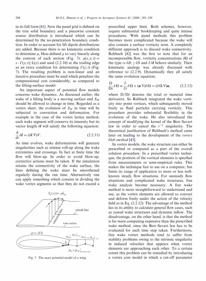

ARTICLE IN PRESS
Fig 11 Interaction of the wake between two partly aligned wind
turbines Reproduced from [88]
MOL Hansen et al Progress in Aerospace Sciences 42 (2006) 285ndash330298
potential flow solvers To overcome some of thelimitations of potential flow solvers a shift towardsunsteady Euler solvers were seen through theeighties [95ndash98] When computing power allowedthe solution of full Reynolds Averaged NS equa-tions the first helicopter rotor computations in-cluding viscous effects were published in the lateeighties and early nineties [99ndash102]
In the late nineties with the CFD solvers capableof handling viscous flow around rotors applicationto wind turbine rotors became of practical interest
The first full NS computations of rotor aero-dynamics was reported in the literature in the latenineties [103ndash107] The European effort to apply NSsolvers to rotor aerodynamics had been madepossible through a series of National and Europeanproject through the nineties The European projectsdealing with development and application of the NSmethod to wind turbine rotor flows was the Viscous
Effects on Wind turbine Blades (VISCWIND) from1995 to 1997 [108] Viscous and Aeroelastic effects on
Wind Turbine Blades (VISCEL) 1998 to 2000[109110] and Wind Turbine Blade Aerodynamics
and Aeroleasticity Closing Knowledge Gaps 2002 to2004 [111ndash115]
242 Approaches
As a consequence of the origin of most CFDrotor codes from the aerospace industry and relatedresearch many existing codes are solving thecompressible NS equations and are intended forhigh-speed aerodynamics in the subsonic andtransonic regime [116ndash120] For the helicopterapplications where compressibility plays an impor-
tant role this is the natural choice For wind turbineapplications however the choice is not as obviousone reason being the very low Mach numbers nearthe root of the rotor blades As the flow hereapproaches the incompressible limit Mach001 itis very difficult to solve the compressible flowequations One remedy to improve their capabilityis the so-called preconditioning that changes theeigenvalues of the system of the compressible flowequations by premultiplying the time derivatives bya matrix On the other hand the compressiblesolvers have many attractive features amongthese the ease of implementation of overlappingand sliding meshes application of high-order up-wind schemes and very well-developed solutionsmethods
Another very popular method especially in theUS is the Artificial Compressibility Method[121122] where an artificial sound speed is intro-duced to allow standard compressible solutionmethods and schemes to be applied for incompres-sible flows In case of transient computations sub-iterations are taken within each time step to enforceincompressibility [122] The method has severalattractive features Among these a similar ease ofimplementation of overlapping grids as the com-pressible codes Overlapping grids are a necessity tosolve rotorstator problems that are present whenthe rotor tower and nacelle are all included in thecomputations The main shortcoming of the methodmay be problems to enforce incompressibility intransient computations without the need for a hugeamount of sub-iterations and the problem ofdetermining the optimum artificial compressibilityparameter
Due to the low Mach number encountered inwind turbine aerodynamics an obvious choice isthus the incompressible NS equations Thesemethods are generally based on treating pressureas a primary variable [123ndash125] Extensions togeneral curvilinear coordinates can be made alongthe lines of [126] The method is not as easilyextended to overlapping grids as the compressibleand the artificial compressibility method due to theelliptical pressure correction equation But themethod is well suited for solving the nearlyincompressible problems often experienced in con-nection with wind energy In connection withsteady-state problems the method can be acceler-ated using local time stepping while the methodusing global time stepping still is well suited fortransient computations
ARTICLE IN PRESSMOL Hansen et al Progress in Aerospace Sciences 42 (2006) 285ndash330 299
243 Turbulence and transition
It is well known that the NS equations cannot bedirectly solved for any of the cases of practicalinterest to wind turbines and that some kind ofturbulence modelling are needed The standardapproach to derive turbulence models is by timeaveraging the NS equation resulting in the so-calledReynolds Averaged NS equations (RANS) Severaldifferent models have been used with good resultsfor wind turbine applications the most successfulones being the k-omega SST model of Menter [127]the SpalartndashAllmaras model [128] and the Bald-winndashBarth model [129] The BaldwinndashLomax [130]model often used in connection with helicopter andfix-wing applications are not very well suited forwind turbine applications where relatively highangles of attack are very common
Several studies performed for stall controlledwind turbines have shown that all RANS modelslack the capability to model the stalled flow regimeat high wind speeds One possible way around thisproblem the so-called Detached Eddy Simulation(DES) technique [131132] has shown some promis-ing results but still needs further validationAdditionally the DES technique is much morecomputationally expensive than the standardRANS approach as it needs much finer computa-tional meshes and the computations needs to becomputed with time accurate algorithms
From experiments it is known that laminarturbulent transition influences the flow over rotorblades for some cases It has been demonstratedfor 2D applications that transition models cangreatly improve the accuracy for cases wheretransition phenomena are important Even thoughnearly all rotor studies so far have been com-puted assuming fully turbulent conditions it isgenerally accepted that it is important to in-clude laminarturbulent transition to model thephysics as close as possible [133134] Predictingtransition in 3D is a much more complex task thandealing with 2D and 3D transition is an activeresearch field
244 Geometry and grid generation
To compute a rotor using CFD the first step is toobtain a digitized description of the blade geometryOften the blade descriptions are given as spanwisesectional information listing the airfoil section thetwist the thickness and the position with respect tothe blade axis Often the blades are highly twistedand with a large taper in the spanwise direction
Depending on the flow solver different ap-proaches to the mesh generation process existCartesian cut cells unstructured and structuredand combinations of these So far the majority offlow solvers applied to wind turbine research haveutilized structured grids with hexahedral cells Inconnection with structured grids there are severalissues that need to be decided upon Generally theproblem of making a high quality grid around amodern rotor cannot be handled by a single blockconfiguration but needs some kind of multi blockmesh These can either be conforming at the blockboundaries non-conforming or overlapping Theoverlapping grids gives the highest degrees offreedom followed by the non-conforming and theconforming grids Firstly the grid needs to accu-rately resolve the blade shape with good resolutionof the leading edge and tip region Secondly thegrids also need to resolve the regions around theblade with sufficient resolutions to capture the flowphysics As the Reynolds numbers are quite high1ndash6 million the cells near the rotor blades becomevery thin as the non-dimensional distance y+ mustbe approximately 1 to resolve the laminar sub-layerand have accurate solutions The mesh generationprocess calls for some degree of experience and gridrefinement studies to verify that the grid is sufficientto resolve the desired physics Also the grids need toextend far away from the rotor in the order ofseveral rotor diameters to avoid disturbing theinduced velocity field near the rotor blades Foraxial flow conditions the flow solvers often takeadvantage of the rotational periodicity of the rotorsolving only for a single blade using periodicconditions
Using an unstructured flow solver with tetrahe-dral cells the grid generation process is lesscumbersome But the problem of resolving verythin boundary layers using tetrahedral cells is wellknown and it may be necessary to combine thesolver with some kind of prismatic grids near theblade surface to avoid this problem The use ofunstructured flow solvers is not wide spread inconnection with wind turbine aerodynamics prob-ably because of the limited geometrical complexityand the strength of unstructured solvers mainlybeing their ability to cope with complex geometries
245 Numerical issues
The codes typically used for wind turbines are ofat least second-order accuracy in both time andspace often with an implicit time discretization
ARTICLE IN PRESSMOL Hansen et al Progress in Aerospace Sciences 42 (2006) 285ndash330300
scheme to loosen the time step restriction inherentto explicit methods Typically the viscous terms arediscretized with central differences while the con-vective terms are discretized with second- or third-order upwind schemes To solve routinely for 5ndash10million grid points the solvers are often available ina parallelized version that allows for execution onseveral CPUrsquos in parallel The rotating nature of theproblem requires the use of either a moving frameincluding the non-inertial acceleration terms or amoving mesh option where so-called mesh fluxesmust be included in the code For a good overviewof the numerical issues in connection with incom-pressible flow see [135]
246 Application of CFD to wind turbine
aerodynamics
The major part of wind turbine rotor computa-tions performed until now has been focused on zeroyaw rotor only configuration where the nacelle andtower have been neglected and the inflow to therotor has been assumed to be steady without shearThis is of course a great simplification but in manycases still a sufficiently good approximation Theeffect of the tower on the rotor on an upwindturbine is comparable to other unsteady effectssuch as incoming turbulence time variations of therotor and of the incoming flow A simulationworking with a full turbine geometry has been tried[106] This type of simulation is much moreexpensive and needs some kind of slidingover-lapping mesh to accommodate the movement of therotor with respect to the turbine tower and nacelleAdditionally the simulation needs to be timeaccurate and good resolution of the flow aroundthe tower is needed to capture the tower wake fardownstream of the turbine
700800900
10001100120013001400150016001700
6 8 10 12 14 16 18 20 22 24 26
Low
Spe
ed S
haft
Tor
que
[Nm
]
Wind Speed [m s]
MeasuredComputed
Fig 12 Comparison of computed and measured low-speed-shaft torque
flow conditions The 7 one standard deviation of the measurements is
One of the first real proofs that CFD for windturbine rotor applications can be useful came inconnection with the blind comparison organized bythe National Renewable Energy Laboratory inBoulder Colorado in December 2000 [136ndash138]Some of these results were later published in[139140] Here several wind turbine research groupswere asked to compute a series of differentoperational conditions for the NREL Phase-VIturbine corresponding to actual cases measured inthe NASA Ames 80 120 ft wind tunnel When theresults were made publicly available it proved thatone of the applied CFD codes were consistentlyreproducing the measured distribution of the aero-dynamic forces along the blade span even underhighly 3D and extreme stall conditions
The output extracted from typical CFD rotorcomputations are the low-speed shaft torque orpower production and root flap moments see Fig12 For modern full size commercial turbines thepower and root flap moment are typically the onlyavailable properties Besides the quantities normallymeasured the CFD simulations provide a hugeamount of detailed information that can be used toprovide more insight The data typically extractedare the spanwise distributions of force coefficientsFig 13 the limiting streamlines on the bladesurfaces Fig 14 and the sectional pressuredistributions along the blade span Fig 15 Forthe NREL Phase-VI turbine these detailed quan-tities can be compared to measurements but this isnot generally the case for commercially availableturbines
Another application of rotor CFD is the study ofdifferent aerodynamic details of the rotor such asthe blade tips the design of the root section etcHere the CFD technique can be used to supply
1000
1500
2000
2500
3000
3500
4000
4500
5000
6 8 10 12 14 16 18 20 22 24 26
Roo
t Fla
p M
omen
t [N
m]
Wind Speed [ms]
MeasuredComputed
and root flap moment for the NREL Phase-VI rotor during axial
indicated around the measured values
ARTICLE IN PRESS
0
05
1
15
2
25
3
02 03 04 05 06 07 08 09 1
CN
rR
MeasuredComputed
-008
-006
-004
-002
0
002
004
02 03 04 05 06 07 08 09 1
CT
rR
MeasuredComputed
Fig 13 Spanwise normal and tangential force coefficients for run S20000000 of the NRELNASA Ames measurements corresponding
to a wind speed of 20ms
NREL PHASE-6 W=10 [m s] Limiting StreamlinesRISOE EllipSys 3D Computation
Fig 14 Limiting streamlines on the surface of the NREL Phase-
VI rotor for the 10ms axial case The picture shows a sudden
leading edge separation around rR frac14 047
-15
-1
-05
0
05
1
15
2
25
3
0 02 04 06 08 1
-Cp
X Chord
rR=063
Fig 15 Comparison of the measured and computed pressure
distribution at the rR frac14 063 section of the NREL Phase-VI
blade the measurements are shown as circles while the
computations are shown with lines
MOL Hansen et al Progress in Aerospace Sciences 42 (2006) 285ndash330 301
information that the engineering methods are notcapable of providing
With the increase in computational power it istoday both possible and affordable to do yawcomputations using CFD [133141ndash143] In contrastto the axial flow cases the total rotor must be
modelled in yaw simulations thereby increasing thenumber of mesh points typically by a factor ofthree Additionally the azimuthally variation in-herent in yaw simulations dictates a time accuratesimulation as no steady state solution can existthereby increasing the computing time severelyTypically a yaw computation will be 10ndash20 timesmore expensive compared to steady state axial flowcomputations Fig 16 shows the normal andtangential force at the rR frac14 30 radius duringone revolution at 601 yaw operation
The release of the measurements on the NRELPhase-VI rotor has heavily influenced the CFDactivities dealing with wind turbine rotor aerody-namics This unique data set with several well-documented cases has given a new possibility to testdetails of state of the art CFD codes In the yearssince the release of the measurements nearly half ofall published CFD studies of wind turbine rotorsdeals with these measurements Besides the refer-ences mentioned other places in this paper thefollowing studies use the NRELNASA Amesmeasurements [144ndash147]
Recently DES simulations of rotors at realisticoperational conditions have been attempted [148]Again the NREL Phase-VI rotor was used to verifythe model The reason for this choice is besides theavailability of detailed measurements the fact thatthe rotor has a limited aspect ratio hence makingthe DES computations more affordable with respectto the number of grid cells The mesh for thissimulation consists of 15 million cells compared toaround 2 million cells for a standard RANS rotorcomputation The fact that DES computations mustbe performed using time accurate computationsmakes these types of simulations 20ndash40 times more
ARTICLE IN PRESS
-2
0
2
4
6
8
10
12
0 50 100 150 200 250 300 350
CN
Azimuth Angle [deg]
S1500600 r R=030
MeasurementsComputed
MeasurementsComputed
-04
-02
0
02
04
06
08
1
0 50 100 150 200 250 300 350
CT
Azimuth Angle [deg]
S1500600 rR=030
Fig 16 Azimuth variation of normal and tangential force coefficient for the NREL Phase-VI turbine at the rR frac14 04 section during a
601 yaw error at 15ms wind speed
MOL Hansen et al Progress in Aerospace Sciences 42 (2006) 285ndash330302
expensive than standard steady-state rotor compu-tations For modern-type rotors with large aspectratios the cell count would be even higher and thecomputations even more expensive For the NRELPhase-VI rotor the improvement using the DEStechnique is very limited but for other rotors wherethe RANS equations do not perform as well DESmay provide much more improvement The use ofpure Large Eddy Simulation has been demon-strated in [149] where a computational grid of 300million points is used to compute the initialtransient of the development of a tip vortex
247 Future
Today NS solvers are an important tool foranalysing different wind turbine rotor configura-tions and are used routinely along with measure-ments and other computational tools fordevelopment and investigation of wind turbinesNS solvers are especially well suited for detailedinvestigation of phenomena that cannot directly beaccessed by simpler and less computationallyexpensive methods Additionally NS methods canbe used as a supplement to measurements wherethey can be used both in the planning phase and tohave a better interpretation of the actual physics inconnection with the analysis of measurements
Finally one of the latest trends is to couple NSsolvers to structural codes to perform full elasticcomputations of wind turbine rotors
3 Structural modelling of a wind turbine
The main purpose of a structural model of a windturbine is to be able to determine the temporalvariation of the material loads in the variouscomponents This is accomplished by calculating
the dynamic response of the entire constructionsubject to the time-dependent load using an aero-dynamic model such as the BEM method Foroffshore wind turbines also wave loads and perhapsice loads on the bottom of the tower must beestimated Two different and frequently usedapproaches to set up a dynamic structural modelfor a wind turbine are described in the nextsubsections
31 Principle of virtual work and use of modal shape
functions
The principle of virtual work is a method to setup the correct mass matrix M stiffness matrix Kand damping matrix C for a discretized mechanicalsystem as
M euroxthorn C _xthorn Kx frac14 Fg (311)
where Fg denotes the generalized force vectorassociated with the external loads p Eq (311) isof course nothing but Newtonrsquos second law assum-ing linear stiffness and damping and the method ofvirtual work is nothing but a method that helpssetting this up for a multibody system and that isespecially suited for a chain system Knowing theloads and appropriate conditions for the velocitiesand the deformations Eq (311) can be solved forthe accelerations wherefrom the velocities anddeformations can be determined for the next timestep The number of elements in x is called thenumber of DOF and the higher this number themore computational time is needed in each time stepto solve the matrix system Use of modal shapefunctions is a tool to reduce the number of DOFand thus reduce the size of the matrices to make thecomputations faster per time step A deflection
ARTICLE IN PRESSMOL Hansen et al Progress in Aerospace Sciences 42 (2006) 285ndash330 303
shape is here described as a linear combination of afew but physical realistic basis functions which areoften the deflection shapes corresponding to thelowest eigenfrequencies (eigenmodes) For a windturbine such an approach is suited to describe thedeflection of the tower and the rotor blades and theassumption is that the combination of the PowerSpectral Density of the loads and the damping ofthe system do not excite the eigenmodes associatedwith higher frequencies In the commercially avail-able and widely used aeroelastic simulation toolFLEX see eg [150] only the first 3 or 4 (2 flapwiseand 1 or 2 edgewise) eigenmodes are used for theblades Results from this model are generally ingood agreement with measurements indicating thevalidity of the underlying assumption First one hasto decide on the DOF necessary to describe arealistic deformation of a wind turbine For instancein FLEX4 17ndash20 DOFs are used for a three bladedwind turbine with 3ndash4 DOFs per blade as describedabove 4 DOFs for the deformation of the shaft (1for torsion 2 for the hinges just before the firstbearing with associated angular stiffness to describebending and 1 for pure rotation) 1 DOF todescribe the tilt stiffness of the nacelle and finally3 DOFs for the tower (1 for torsion 1 for the firsteigenmode in the direction of the rotor normal and1 in the lateral direction)
The method of virtual work will only be brieflydescribed For a more rigorous explanation of themethod the reader is referred to textbooks ondynamics of structures The values in the vectordescribing the deformation of the construction xiare denoted the general coordinates To eachgeneralized coordinate is associated a deflectionshape ui that describes the deformation of theconstruction when only xi is different from zero andtypically has a unit value The element i in thegeneralized force corresponding to a small displace-ment in DOF number i dxi is calculated such thatthe work done by the generalized force equals thework done on the construction by the external loadson the associated deflection shape
Fgidxi frac14
ZS
p uidS (312)
where S denotes the entire system Please note thatthe generalized force can be a moment and that thedisplacement can be angular All loads must beincluded ie also gravity and inertial loads such asCoriolis centrifugal and gyroscopic loads The non-linear centrifugal stiffening can be modelled as
equivalent loads calculated from the local centrifu-gal force and the actual deflection shape as shown in[151] The elements in the mass matrix mij can beevaluated as the generalized force from the inertialoads from an unit acceleration of DOF j for a unitdisplacement of DOF i The elements in the stiffnessmatrix kij correspond to the generalized force froman external force field which keeps the system inequilibrium for a unit displacement in DOF j andwhich then is displaced xi frac14 dij where dij isKroneckers delta The elements in the dampingmatrix can be found similarly For a chain systemthe method of virtual work as described herenormally gives a full mass matrix and diagonalmatrices for the stiffness and damping For oneblade rigidly clamped at the root (cantilever beam)it is relatively easy to estimate the lowest eigen-modes (first flapwise u1f(x) first edgewise u1e(x) andsecond flapwise u2f(x)) eg using an iterative methodas described in [151] The eigenmodes are normallydescribed in a coordinate system aligned with the tipchord as eg shown in Fig 1 It is practical tonormalize the deflection shapes so that the tipdeflection is unity It is now assumed that anydeflection can be described as a linear combinationof these modes as
uethxTHORN frac14 x1u1f ethxTHORN thorn x2u
1eethxTHORN thorn x3u2f ethxTHORN (313)
The velocity and accelerations can be calculatedrespectively as
_uethxTHORN frac14 _x1u1f ethxTHORN thorn _x2u
1eethxTHORN thorn _x3u2f ethxTHORN (314)
and
eurouethxTHORN frac14 eurox1u1f ethxTHORN thorn eurox2u
1eethxTHORN thorn eurox3u2f ethxTHORN (315)
The advantage of the method using generalizedcoordinates and modal shape functions is that thenumber of DOF in the dynamic system can bereduced to a relatively small number Further somehigh eigenfrequencies are filtered away which isbeneficial for the allowable time step when comput-ing deformations xnthorn1
i and velocities _xnthorn1i at time
t frac14 (n+1)Dt from deformations xni velocities _xn
i and accelerations euroxn
i at time t frac14 nDt A goodchoice for the time integration scheme is theRungendashKuttandashNystrom method which requiresfor stability reasons that the time step shouldresolve the highest eigenfrequency with 4 pointsbut for accuracy reasons 10 points is preferredBy reducing the highest eigenfrequency using amodal description of eg the blades not only
ARTICLE IN PRESSMOL Hansen et al Progress in Aerospace Sciences 42 (2006) 285ndash330304
reduces the number of DOFs but also larger timesteps can be taken
32 FEM modelling of wind turbine components
applying non-linear beam theory
Even though modal analysis offers a computa-tionally effective way to analyse wind turbinedynamics most of the recently developed aeroelasticcodes use a full FEM approach [152] which allowsa more complex deformation state of the windturbine The main features of such modellingprocedures together with some aspects of non-linearbeam theory are discussed in the present section
The structural modelling of wind turbines isbased on beam theory For a 1D structure (beam)subjected to bending in two directions torsion andaxial tension the formulation of the problemconsists of two parts (a) the elastic model whichreduces the 3D structure of each component into a1D structure concentrated along the elastic axis ofthe beam and (b) the derivation of the dynamicequations In classical beam theory (first order) thedeformed position r of any point initially at x0 frac14ethx y zTHORNT (Fig 17) can be described by the displace-ment vector u frac14 fu vw ygT consisted of the two
Undeformed geometry
x
z
u
wr
zF +
Mx
Fx
Mz
FzMy
Fy
x
z
(a)
a
b
Fig 17 Kinematics and dynam
bending displacements u w the torsion angle y andthe tension v
r frac14 n0 thorn S0 uthorn S1 yu
S0 frac14
1 0 0 z
0 1 0 0
0 0 1 x
264
375
S1 frac14
0 0 0 0
x 0 z 0
0 0 0 0
264
375
(321)
Using Hookersquos law and assuming that shear stressesdo not produce net torsion the sectional elasticloads can be derived
Fy frac14 ethEATHORNqyv ethEAxTHORNq2yyu ethEAzTHORNq2yyw
My frac14 ethGItTHORNqyy
Mx frac14 ethEIxzTHORNq2yyuthorn ethEIxxTHORNq
2yyw ethEAzTHORNqyv
Mz frac14 ethEIzzTHORNq2yyu ethEIxzTHORNq
2yywthorn ethEAxTHORNqyv
eth322THORN
where the terms in parentheses denote the averagedsectional properties of the structure By consideringthe balance of loads and moments on of a beam
Deformed geometrydy
y
A
u+du
w+dwDeformed elastic axis
M + dMz
z
z
M + dMyy
M + dMxx
dF
yyF + dF
xxF + dFdr
ra
δPy
A(b)
ics of a beam structure
ARTICLE IN PRESS
x
z
yu
w
vO
Orsquoz
xz
xu
w θtθ
ζ
ξ
ξ
θθ
θ +ˆ
Fig 18 Beam co-ordinate system definition
MOL Hansen et al Progress in Aerospace Sciences 42 (2006) 285ndash330 305
element of length dy the beam equations arederivedZ
A
eurordm
dy frac14 dFthorn
ZA
g dm
dythorn dpdy
(323)
ZA
r0 eurordm
dy frac14 dMthorn dr ethFthorn dFTHORN
thorn
ZA
r0 gdm
dythorn ra dpdy eth324THORN
where m denotes the mass per unit length dF dMare the net elastic loads on dy g is the accelerationof gravity and dp the sectional aerodynamic loadsexerted at the aerodynamic centre ra frac14 ethxa 0 zaTHORNwhile
r0 frac14 fduthorn xthorn zy dvthorn dydwthorn z xygT
ffi fxthorn zy dy z xygT
In view of a more systematic and general frameworkfor formulating dynamic equations Hamiltonrsquosprinciple has been also used [153154]
By introducing (322) into (323) and (324) thebeam dynamic equations are obtainedZ
A
ethS0THORNT euror dm qy
ZA
ethS1THORNT euror dm frac14 qyfrac12K11 qyu
thorn q2yyfrac12K22 q2yyu thorn qyfrac12K12 q
2yyu
thorn q2yyfrac12K21 qyu thorn
ZA
ethS0THORNT g dmthorn Sa dP
eth325THORN
K11 frac14
Fy 0 0 0
0 EA 0 0
0 0 Fy 0
0 0 0 GIt
2666664
3777775
K22 frac14
EIzz 0 EIxz 0
0 0 0 0
EIxz 0 EIxx 0
0 0 0 0
2666664
3777775
Sa frac14
1 0 0
0 1 0
0 0 1
za 0 xa
2666664
3777775
K12 frac14
0 0 0 0
EAx 0 EAz 0
0 0 0 0
0 0 0 0
2666664
3777775
K21 frac14
0 EAx 0 0
0 0 0 0
0 EAz 0 0
0 0 0 0
2666664
3777775
In case of flexible blades if large deformations areexpected as in the case of helicopter blades second-order non-linear beam theory is to be used Therelevant developments originate from the work in[154] The beam axis again lies along the y-axis butin the undeformed state of the beam while x and z
denote the two bending directions of the beam Atits deformed state a local co-ordinate system O0xZzis introduced which follows the pre-twist of thebeam so that x and z coincide with the localstructural principle axes of the cross section(Fig 18)
Then (321) becomes
r frac14
u
ythorn v
w
8gtltgt
9gt=gtthorn E
x
lyy
z
8gtltgt
9gt=gt (326)
where l denotes the warping function of the crosssection and E is the transformation matrix betweenOxyz and O0xZz In [154] E is given in terms of theelastic displacements up to second order Next thestrain tensor ij defined through (326) is introducedin Hookersquos law in order to define the strainndashdispla-cements relations which are used in the derivationof the resulting sectional elastic loads as in (322)Because they are derived in the O0xZz system beforeintroducing them in (323) and (324) they aretransformed into the Oxyz system using the
ARTICLE IN PRESS
ρk
rGk
OG O
xG x
zG z
yG
y y
z
x
O
x
y
z
O
Fig 19 Multi-body representation of a wind turbine
MOL Hansen et al Progress in Aerospace Sciences 42 (2006) 285ndash330306
transformation matrix E The final expressions arequite lengthy and the reader is referred to [154] It isnoted that compared to the classical beam modelsecond-order theory will produce fully completestiffness matrices containing many non-linear termsThe above non-linear beam model is a specificexample amongst several models of varying com-plexity which have been gradually developed start-ing from the Timoshenko beam theory byeliminating the ad hoc simplifying assumptions ofthe original model [155ndash158]
Regarding wind turbines almost all structuralmodels are based on classical beam theory[150153159ndash162] This is partially due to the factthat wind turbine components are far more rigidcompared to helicopter blades for which non-lineartheory has been developed Furthermore most of thedifficulties in analysing wind turbine systems aregenerated by the aerodynamics and in particular theonset of stall which is certainly less pronounced onhelicopter rotors Current designs are quite stiff sothat non-linear beam modelling is not expected tochange drastically the quality of predictions besidesproviding a sound basis for including the geometricalnon-linearities [163] However if wind turbinesbecome more flexible it could become necessary toadopt such kind of structural modelling
Regardless the details the beam equations arefourth order with respect to bending and secondorder with respect to tension and torsion So for aFE approximation of the equations C1 shapefunctions are used for uw and C0 for v and y Atthe element level uw are approximated with third-order polynomials and the DOFs are the values andspace derivatives at the end nodes while v and y areapproximated with first-order polynomials and theDOFs again at the end nodes In some models andcertainly when the second-order beam theory isapplied second- and third-order polynomials areused respectively for v and y In this case the mid-point as well the points at 13 and 23 interior pointsare used as nodes So within an element lsquolsquoersquorsquo
ueethy tTHORN frac14 NeethyTHORN ueethtTHORN (327)
where NeethyTHORN is the matrix containing the shapefunctions and ueethtTHORN the vector of the DOFs at thenodes of the elements [164] As in Section 31concerning the principle of virtual work which inthe FEM terminology is the Galerkin formulationof the problem is used to generate the discreteequations With reference to (325) taken symboli-cally as Zethu _u eurouTHORN frac14 0 for any admissible virtual
displacement field du we require that
Z L
0
duT Zethu _u eurouTHORNdy
X
e
Z Le
0
duTe Zethue _ue euroueTHORNdy frac14 0 8du eth328THORN
Because dueethy tTHORN frac14 NeethyTHORN dueethtTHORN it follows that
Xe
Z Le
0
NeT ZethNeueNe _ueN
e euroueTHORNdy frac14 0 (329)
which is a set of second-order ordinary equations intime with respect to ueethtTHORN Although Z can containnon-linear terms it can always be written in theusual form
MethuTHORN eurouthorn Cethu
THORN _uthorn Kethu
THORN u frac14 Qethu
THORN (3210)
where the mass damping and stiffness matrices aswell as the generalized loads in the RHS in generalwill depend on the displacement field and its timeand space derivatives (noted by a tilde)
ARTICLE IN PRESS
y
O
q8 q9 q10 q11q12 q13
yG y
z
x
O
x
y
z
OG O
xG x
zG z
q1 q2 q3 q4q5 q6
q7
q14
Fig 20 A typical definition of the q DOF on a HAWT
MOL Hansen et al Progress in Aerospace Sciences 42 (2006) 285ndash330 307
The main components of a wind turbine are theblades the drive-train and the tower (Fig 19) Theyare all modelled as beam structures and typically thestructural properties are assumed for each compo-nent to continuously vary along the correspondingelastic axis However localized properties can beadded in the form of concentrated masses dampersor springs The gearbox (if present) the generatorthe hub are usually added in this way Otherexamples are the flexibility or damping character-istics of the yaw bearing or the pitch mechanismThe involvement of different body motions for eachcomponent in combination with the connectionswhere loads and displacements are communicatedfrom one component to the other calls for a globalformulation of the dynamic problem To this endmost works adopt a multi-body approach [165]which consists of considering each componentseparately subjected to appropriate boundary con-ditions which fit the different components into thecomplete configuration In such an approach theelastic DOF of each component are defined as localelastic displacements to which rigid body motionsare added through the kinematic boundary condi-tions see eg [161166167] for a more generaldiscussion It is also possible to introduce the globaldisplacements and rotations at each node instead ofthe local ones [153] allowing a unified description ofthe complete configuration In this case howeverthe non-linearities of the connections are introducedimplicitly and therefore linearization can only beperformed globally which is not always desirable
In multi-body modelling each component k isassigned a local coordinate system Oxyz with itsundeformed elastic axis along the y-axis Then theposition of a point with respect to the fixed systemrGk can be expressed with respect to its localposition rk (defined as in (321)) as follows
rGk frac14 qk thorn Ak rk (3211)
where qk denotes the position of the origin of thelocal system with respect to the fixed system and Ak
denotes the local to global transformation matrixThe exact form of qk and Ak depends on thekinematic conditions introduced when joining (con-necting) the various components (ie blades-to-hubor drive-train-to-tower) Depending on the type ofconnection common global displacements androtations are assigned for the restricted DOF whichare identified to either an existing elastic DOF (shaftbending at the hub) or a rigid body motion (bladepitch) The component contributing the kinematics
will in response receive from the rest of theconnected components their internal (or reaction)loads This operation involves co-ordinate systemtransformations between the components The setof kinematical DOF involved in the definition of qk
and Ak for all components is denoted collectively asq So qk frac14 qk(q t) and Ak frac14 Ak(q t) qk is defined asa mixed series of translations and rotations whereasAk is defined solely as a sequence of rotations Atypical example is shown in Fig 20 where q1ndashq6 arethe elastic DOF at the top of the tower q8ndashq13 arethe elastic DOF of the drive train at the hub and q7and q14 are the yaw angle and the pitch of the bladerespectively By introducing (3211) into (325) thecentrifugal and Coriolis terms of the inertia loadsappear as a result of the time derivatives of Ak whilein the Hamiltonrsquos principle approach they areproduced automatically
By combining the equations of all componentsthe complete system of the dynamic equations forthe wind turbine is obtained in the form of (3210)with respect to an extended vector of DOFuext frac14 u q
By construction qk and Ak will depend
on unknown DOF while at the same time theycorrelate the state of the components in contact sothe terms they generate are non-linear with respectto the unknown DOF uk and q Linearization in thiscase is a tedious procedure which must be donecarefully and systematically Fortunately softwareusing symbolic mathematics such as Mathematica
ARTICLE IN PRESSMOL Hansen et al Progress in Aerospace Sciences 42 (2006) 285ndash330308
are available which are strongly recommended Theprocedure is based on Taylorrsquos expansions of allvariables and retaining of first-order terms Alter-natively the extended version of (3210) can besolved directly through an iterative procedure ineach time step which can use the linearized solutionas a starting predictor
4 Problems and solutions in wind turbine
aeroelasticity
In the following section the use of aeroelasticcodes on wind turbine constructions includingstability studies will be illuminated mainly throughexamples
41 Aeroelastic stability
Wind turbines suffer from low structural damp-ing which can become critical under certain opera-tional conditions Most problems appear on theblades that receive almost 100 of the loading Inparticular the onset of stall plays a decisive role notonly on stall-regulated machines but also on pitch-regulated ones around rated conditions On theother hand the blades are made of compositematerials for which the knowledge on damping issubstantially inferior compared to steel or concreteconstructions The damping of composite structuresdepends on the ambient temperature So dependingon the season or the time during the day thestructural damping of the blades can decreasesubstantially Furthermore aging always degradesthe damping of composite structures There is adefinite need to increase structural damping andsignificant effort has been put recently on itsmodelling in composite structures as well as in theirappropriate design This is one direction of researchregarding the improvement of the stability char-acteristics of modern wind turbines see [168] for areview of the current developments Damping isrequired to suppress the onset of vibrationsgenerated by the unsteady aerodynamic loads thatinteract with the wind turbine structure First theaeroelastic modelling of wind turbines is consideredand then on this basis the aeroelastic stabilityproblem is formulated and the relevant availablemethods are reviewed
Aerodynamic modelling involves the calculationof the aerodynamic loads that also depend on thedynamics of the system The flap and lag vibrationsare interpreted by the incoming flow as a change in
the effective angle of attack indicating strongaeroelastic coupling All the currently availableaeroelastic tools for wind turbines use 2D dynamicairfoil data models such as the BeddoesndashLeishmannor the ONERA model They provide aerodynamiccoefficients as functions of the aerodynamic statevariables that satisfy appropriate dynamic equa-tions [17169] In either model the equations are 2Dand so they are applied on a strip-by-strip basismeaning that there is no interaction in the radialdirection This fits well with BEM modelling of theoverall aerodynamic analysis In fact the followingpresentation is referred to the BEM context sincemost existing stability models are based on it If apotential flow model is applied then the attachedpart of lift can be associated to potential lift whilethe rest is simply added [163] If the potential flowmodel is enhanced with a separation model thereshould be correlation on both aspects [58] How-ever the latter has not been applied yet inaeroelastic computations
By considering a blade section at a radial positionas shown in Fig 1 the local aerodynamic loadsacting on this section of the blade can be written asfollows since the lift is perpendicular and the dragparallel to the relative wind
py frac14 L sin fD cos f
pz frac14 L cos fthornD sin f
My frac14M eth411THORN
where L D are the lift and drag forces M is thepitching moment f is the local flow angle withrespect to the rotor plane Once the induced velocityhas been determined the local effective incidence aand relative flow velocity can be calculated as shownin Section 21 They will depend on the elasticdeformations and the velocities the rigid bodymotions and if appropriate orientation changes asin pitch and yaw variations In order to obtain aunified description of the coupled aeroelasticproblem a so-called aeroelastic finite element isdefined [170] which in addition to the elastic DOFthe aerodynamic state variables added For examplein the ONERA model there will be in total eightadditional DOF Because the dynamic equations forthe aerodynamic state variables only can be firstorder in time in order to produce a consistentcoupled system they can be differentiated as in[171] Therefore they can be assembled togetherwith the dynamic equations in the form of (3210)where the vector of the unknowns is further
ARTICLE IN PRESSMOL Hansen et al Progress in Aerospace Sciences 42 (2006) 285ndash330 309
extended to include the additional aerodynamicDOF Another approach used in [172] is tointroduce the modal expansion of the structuralDOF at stand still which better conditions thecoupled system
On the above basis it is possible to formulate theaeroelastic stability problem for wind turbinesWithin the context of linear theory stabilityboundaries are obtained by examining the evo-lution of small perturbations with respect to asteady state or a periodic solution acting asreference To this end the original equations arelinearized with respect to the reference state andthe resulting system solved with respect to thefluctuations
Methuref THORN eurouthorn Cethuref THORN _uthorn Kethuref THORN u frac14 Q (412)
where M C and K depend only on the referencesolution If the matrices do not depend on time(412) is reformulated into a first-order system
_y frac14 D ythorn b y frac14 u _un oT
(413)
The eigenvalue analysis of D provides the eigen-frequencies and damping of the system [173] This ispossible when the reference state corresponds to asteady solution as in the case of an isolated bladeHowever when analysing the complete windturbine configuration due to the rotation of theblades the reference state should correspond to aperiodic equilibrium state with reference to the rotorspeed which is assumed constant In this case thecorresponding theoretical framework is Floquetrsquostheory which for a large system is computationallyheavy [174] If the blades are identical and thenumber of blades NX3 which is the most frequentcase it is possible by means of multi-bladetransformation to eliminate the periodic coefficientsin the coefficients of (412) and therefore be ableto still use eigenvalue analysis [175] In this contextthe non-linear equations of the system are inte-grated in time until such a periodic state is attainedIn the case of an unstable situation because thetime domain response will contain significantcomponents in all of the basic eigenfrequencies ofthe system the reference state is obtained bytruncating the response so as to retain only its 1and Nrev components To this end all DOF in therotating system qm m frac14 1 NX3 are reformedqm frac14 q0 thorn qc cos cm thorn qs sin cm where cm frac14 Otthorn
eth2p=NTHORNethm 1THORN is the corresponding azimuth loca-tion Next the equations for the blade DOFs are
rearranged by applying the operators eth1=NTHORNPN
mfrac141
eth THORN eth2=NTHORNPN
mfrac141eth THORN cos cm and eth2=NTHORNPN
mfrac141eth THORN
sin cm This is performed after the periodic solutionhas been obtained over one period of rotation Theresulting equations will be in the non-rotating frameand contain only higher harmonics (3rev andhigher) By averaging over one period the finalconstant coefficient system is obtained in the formof (413) For the blades y will contain thecorresponding q0 qc and qs DOF and their timederivatives for both the purely structural and theaerodynamic DOF [171] In the above approach it isworth noticing that the averaging procedure willforce the reference state to appear in the equationsThis is an important aspect when dealing with non-linear systems
Stability of wind turbines has been consideredsystematically in Europe in the late 1990s [176] whiletoday there is an on-going activity under the EUfunded project STABCON Several linear stabilitytools have been produced along the lines describedabove and good correlation has been obtainedamongst the different codes see [177] and thereferences cited Inevitably linear theory is approx-imate so the results it produces are subject to crosschecking Clearly flutter measurements are difficultto obtain because of the involved risk therefore it isindispensable to rely on theoretical developmentswhich will be discussed in the next section
42 Aeroelastic coupling linear vs non-linear
formulations
Linearization of the aeroelastic equations cer-tainly offers computational efficiency However it isnot always appropriate For the structure lineartheory requires that the deformations and displace-ments are small an assumption not always validFor the aerodynamics and its coupling with thestructure linearization will suppress some depen-dencies involved in (411) and therefore influencethe estimation of the aerodynamic damping In thisconnection the use of semi-empirical unsteadyaerodynamic models introduces still unresolveduncertainties Furthermore there are cases in whichthe multi-blade transformation is not applicable egwhen blades are non-identical or when the rota-tional speed varies
Retaining fully the non-linearities of the aero-elastic problem has the following consequences thestructure is considered at its deformed state thecoupling conditions among the components are
ARTICLE IN PRESSMOL Hansen et al Progress in Aerospace Sciences 42 (2006) 285ndash330310
taken in their full form and the aerodynamicequations are not simplified The last point isimportant with respect to the best possible estima-tion of the aerodynamic damping within themargins offered by the semi-empirical models usedin the currently available aeroelastic tools In thisrespect multi-body analysis which has beenadopted in most of the existing stability tools[161178ndash181] offers this option by constructionprovided that the structural model considers theconstruction at its deformed state and the codetakes this into account in the definition of the localaerodynamics
Under such conditions the information of thestability characteristics of the wind turbine arecontained in the time signals of the loads calculatedthrough a non-linear time domain simulation Thereexist two types of methodologies for retrieving thisinformation the one is based on the work-basedapproach [176] while the other is using signal-processing techniques In the work-based methodany mode shape is excited and loads are recordeduntil a steady periodic state has been reached Thenthe aerodynamic damping is estimated by the workof the aerodynamic loads over the last period underthe assumption that there is no energy interchangebetween the modes through the aerodynamic loadsIn the signal processing approach the system isharmonically excited for a finite duration Then thetransient response following the abrupt terminationof the excitation is recorded wherefrom the aero-elastic damping and frequency of the specific modeare determined There are two different methodsboth well documented in the literature [182ndash184]that can be used the moving block method and themethod of Hilbert transform The moving blockmethod is a FFT based method commonly used inrotorcraft applications [182184] The transientresponse amplitude is computed on a block of datausing a FFT calculation The block is then movedforward by a single point in time and the computa-tion of the transient response amplitude is repeatedThe linear fit for the slope of the natural logarithmof the sequence of response amplitudes in time(peak plot) provides the damping (Fig 21) In theHilbert method the transient response y(t) and itsHilbert transform ~yethtTHORN are used to define theenvelope signal AethtTHORN frac14
ffiffiffiffiffiffiffiffiffiffiffiffiffiffiffiffiffiffiffiffiffiffiffiffiffiy2ethtTHORN thorn ~y2ethtTHORN
p[183184]
For a transient response typical of a viscouslydamped system a line can be fitted to the logarithmof this envelope The slope of this line as in the caseof the moving block method gives the damping
(Fig 22) Comparing the two it has been found thatthe Hilbert method has certain advantages over themoving block method In particular the Hilbertdamping analysis provides an estimate of thedecaying envelope signal so it can be used inassessing the non-linear damping characteristics ofa mode Therefore it is not limited by the assump-tion of the viscous damping as the moving blockmethod does Moreover experience has shown thatthe Hilbert method is more efficient in calculatingthe damping of spectrally close modes [163]
43 Examples of time simulations and instabilities
In this section the challenges in aeroelastic design ofwind turbine rotors will be addressed and in particularthe phenomenon of aeroelastic instability of windturbine rotors will be explored by showing examplesof simulation results on a wind turbine design
Back from the beginning of development ofmodern wind turbine rotors in the late seventiesthere has been concern about the problems thatcould arise due to aeroelastic instability In parti-cular the use of the stall regulation principle wasuncertain as it was foreseen that a flapwiseinstability (so-called stall flutter) would occur whenoperating in the stall region due to the negativeslope of the CL vs a curve However it turned outthat the flapwise instability during operation in stallwas not the most critical problem but instead theedgewise instability resulting in edgewise bladevibrations The first experimental evidence of thisinstability was seen in the mid nineties and initiatedconsiderable research activities in order to explorethe phenomenon and provide practical solutionsBelow is mainly focused on this instability as thisserves as a good example to illustrate the problem ofaeroelastic instability in more general terms
In the more recent wind turbine designs theregulation of the turbines has shifted from stallregulation to pitch control where the operationalrange for the flow over the blade moves to low angleof attack at high wind and thus away from the stallregion This has almost removed the instabilityassociated with stall during operation but it is stillso that the edgewise blade modes are aerodynami-cally low damped on the pitch regulated turbines
A major instability problem on the modernturbines is seen when the rotor is parked or idlingat very low RPMs at wind speeds above stop windspeed which typically is around 25ms Again it istypically edgewise dominated instability problems
ARTICLE IN PRESS
3540
4550
tim
e (s
ec)
-35
E+
06
-3E
+06
-25
E+
06
-2E
+06
-15
E+
06
-1E
+06
tower top tilt bending moment (Nm)
12
34
freq
uenc
y (H
z)
0
5E+
08
1E+
08
15E
+08
2E+
08
25E
+08
3E+
08
FFT of the tower top tilt bending moment (Nm)
Δt
data
19
190
5
191
191
5
192
192
5
193
193
5
194
00
51
15
22
53
t (se
c)
-ζ Ω
n
log of response amplitude
Fig21Schem
aticdescriptionofthemovingblock
dampinganalysis
MOL Hansen et al Progress in Aerospace Sciences 42 (2006) 285ndash330 311
ARTICLE IN PRESS
-15e+06
-1e+06
-500000
0
500000
1e+06
15e+06
2 4 6 8 10 12 14
tow
er to
p til
t ben
ding
mom
ent (
KN
m)
time (s)
transient signalenvelope signal
envelope signal exp fit
Fig 22 Envelope signal calculation of the tower top tilting moment transient response using the Hilbert transform method for the same
signal as in Fig 21
1000
800
600
400
200
0
-2000 50 100 150 200 250 300
Time [sec] Time [sec]
ED
GE
WIS
E B
LA
DE
RO
OT
MO
ME
NT
[U
NC
AL
IBR
AT
ED
]
ED
GE
WIS
E B
LA
DE
RO
OT
MO
ME
NT
[U
NC
AL
IBR
AT
ED
]
EDGEWISE BLADE VIBRATION INSTABILITY EDGEWISE BLADE VIBRATION INSTABILITY--MEASUREMENT
1000900800700600500400300200100
0-100
200 210 220 230 240 250 260
Fig 23 Measured edgewise blade root moment on a stall regulated rotor at high wind Detail of the time track to the right
MOL Hansen et al Progress in Aerospace Sciences 42 (2006) 285ndash330312
related to stall of the blade A simulation examplewill be shown later to illustrate this problem
Finally the flutter instability will be addressed Itseems that the increased up scaling of the turbineshas led to rotor and blade designs where the flutterspeed is not so far away from normal operationalspeed Also this instability will shortly be illustrated
431 Edgewise blade vibration instability
As mentioned above the first experimentalevidence of this instability was seen in the mid
nineties on stall-regulated rotors with a diameter of35ndash40m An example is presented in Fig 23 and it isseen that the amplitude of the edgewise blade rootmoment (which at steady conditions vary sinusoidalwith 1p due to the gravity) increases 2ndash3 times dueto instability during operation in stall The experi-mental evidence of the edgewise instability led toconsiderable research on this subject and a majorEuropean project lsquolsquoPrediction of Dynamic Loadsand Induced Vibrations in Stallrsquorsquo funded by the EUwas carried out in the period from 1995ndash1998 [176]
ARTICLE IN PRESSMOL Hansen et al Progress in Aerospace Sciences 42 (2006) 285ndash330 313
The origin of the instability is simple If a rotatingairfoil section is harmonically translated along anaxis xB and the direction of this axis yRB relative tothe orientation xR of the rotor plane is varied theaerodynamic damping coefficient for the sectionvaries considerably see Fig 24 from [185] For lowyRB which means in-plane or edgewise vibrationdirection the damping coefficient is negative even atlow wind speed For vibrational directions close to901 which corresponds to out-of-plane or flapwisedirection the damping coefficient is strongly depen-dent on the inflow wind speed It is highly damped
Fig 24 The aerodynamic damping coefficient c_xx_b for a rotating a
different inflow velocities from [185]
Fig 25 Damping characteristics computed for a rotating isolated bl
at low wind but close to zero or negative damped athigh wind
On a complete rotating blade the direction ofvibration depends on the structural design of theblade as well as of the complete turbine structureThe movement of the tip section of the blade willnow no longer necessarily be along a straight lineHowever typically the tip section of the blade in thefirst flapwise mode will be on a path almostperpendicular to the rotor plane and in the 1stedgewise mode it will almost be in-plane It is thusexpected that the basic damping characteristics of
irfoil section as function of vibration direction yRB and at three
ade using the linear aeroelastic stability tool HAWCStab [186]
ARTICLE IN PRESSMOL Hansen et al Progress in Aerospace Sciences 42 (2006) 285ndash330314
the whole blade will be comparable with thecharacteristics of a single airfoil section Using thelinear stability tool HAWCStab the dampingcharacteristics for a rotating blade can easily bederived and the computed damping characteristicsfor a rotating 19m blade (500 kW rotor) corre-sponding to the blades of the rotor where theexperimental instability was shown in Fig 23 areshown in Fig 25 from [186] It is seen that thedamping for the first flapwise mode varies fromhighly positive values at low wind speed and tovalues close to zero at 14ms and then increasingslightly at higher wind speeds It should be notedthat the influence of using unsteady blade sectionaerodynamics is shown (modelled with the BeddoesLeishman model in the present case) and that thishas considerable influence on the aeroelastic damp-ing Generally the unsteady aerodynamic effectsincrease the damping The damping for the firstedgewise mode is seen to decrease gradually withincreasing wind from being slightly positive at lowwind to slightly negative at high wind Finally itshould also be noted that the damping shown is thetotal damping including the structural dampingwhich in the present case is around 2 for the firstflapwise mode and 3 for the first edgewise mode
The final step in model complexity is nowobtained by going to a full aeroelastic model ofthe turbine comprising the dynamics of the shaftthe nacelle and the tower The aeroelastic stability
Fig 26 Aeroelastic damping computed with the aeroelastic stability HA
speed
results using HAWCStab is for the complete windturbine see eg Fig 26 from [186] showing theaeroelastic damping for the first 10 mode shapes(numbered from lowest frequency) It is seen thattwo mode shapes are negatively damped at highwind speed and that one mode shape is close to zeroand slightly negatively damped at the highest windspeed For comparison time simulations with theaeroelastic code HAWC [187188] is performed onexactly the same turbine model at a wind speed of 8and 16ms respectively in order to see if theinstability at high wind speed predicted by the linearstability tool can be confirmed by the HAWCmodel with non-linear aerodynamics The com-puted edgewise blade root moment shown in Fig 27confirm the instability at high wind and comparesvery well with the measured instability shown inFig 23 It is thus demonstrated that the edgewiseinstability problem can be predicted in both timesimulations and using linearized stability analysisHowever as will be demonstrated below theedgewise vibration instability is much more complexthan just edgewise vibrations of the individualblades but comprises the dynamic characteristicsof the whole turbine This understanding is vital forthe development of design solutions preventing theinstabilities
In order to analyse the instability in more detailsthe use of parallel aeroelastic time simulations on aturbine with a stiff structure is made In this case the
WCStab [186] Three modes have negative damping at high wind
ARTICLE IN PRESSMOL Hansen et al Progress in Aerospace Sciences 42 (2006) 285ndash330 315
loads on the different components will mainlyreflect the direct load input from the externalaerodynamic forces and from gravity forces Itshould be mentioned that the simulations areperformed at two average wind speeds of 8 and16ms respectively and with a turbulence intensityof 12
A power spectral density analysis of the simulatededgewise blade root moment shows a distinct peakat 307Hz which is close to the frequency of the firstedgewise mode for a single rotating blade which is319Hz see Fig 28 The response at 16ms of theflexible turbine at this frequency is seen to be severalorders of magnitude bigger than the response of thestiff turbine indicating an instability situationSomewhat the same tendency is seen at 8ms but
Fig 28 Comparison of power spectra of edgewise blade root momen
Fig 27 Time simulation with the aeroelastic code HAWC on a 50
with considerable less difference between the re-sponse of the stiff and flexible turbine indicating lowdamping but not an instability
Analysing further the results of the stabilityanalysis with HAWCStab as shown in Fig 26 itcan be derived from the results of the model that thethree mode shapes that are negatively damped orvery low damped at 16ms are
t fo
0 k
mode no 1 with frequency 077Hz and damping605
mode no 3 with frequency 093Hz and damping433
mode no 7 with frequency 273Hz and damping
159
r a flexible and a stiff turbine respectively at 8 and 16ms
W stall regulated rotor at two wind speeds 8 and 16ms
ARTICLE IN PRESSMOL Hansen et al Progress in Aerospace Sciences 42 (2006) 285ndash330316
The numbering in HAWCStab of the modes iswith increasing mode number with increasingfrequency starting with the lowest frequency Modeno 1 and no 3 are both modes where lateral towerbending is the main motion together with edgewisebending of the three blades and torsion of the mainaxis The edgewise movement of the blades are all inphase and the difference between the two modes isthe direction of the edgewise bending relative to thetower bending Comparing again the results of thelinear stability analysis with the time simulationresults the instability of the lateral tower bendingdominated modes is confirmed by the spectra of thetower top and tower bottom lateral bendingmoments Figs 29 and 30 A distinct peak at
Fig 29 Comparison of power spectra of tower top lateral moment
Fig 30 Comparison of power spectra of tower bottom lateral mome
079Hz is seen in both tower top and tower bottomspectra at 16ms and this peak cover probably alsoa considerable content at the 093Hz which was thefrequency of mode no 3
It can be noticed that the HAWCStab results donot contain an unstable mode with a frequencyaround 307Hz (the edgewise instability) as seen inthe time simulation results However mode no 7 isin fact the response on the non-rotating turbinestructure from the edgewise vibrations at 307HzThe edgewise vibrations in the present case is a so-called backward whirling edgewise mode wherethere is a phase shift of 1201 between the movementof the blades This whirling mode results in shaftand tower bending but with a frequency shifted 1p
for a flexible and a stiff turbine respectively at 8 and 16ms
nt for a flexible and a stiff turbine respectively at 8 and 16ms
ARTICLE IN PRESSMOL Hansen et al Progress in Aerospace Sciences 42 (2006) 285ndash330 317
(p is the rotational frequency) up and downrespectively compared with the frequency in therotating system As 1p in the present case is 045Hza peak in the spectra of tower bending at afrequency of around 307ndash045Hz equal to 262Hzis expected which is also seen in Figs 28 and 29However in the HAWCStab results a slightlyhigher frequency 273Hz was seen for this mode
The presented example of the edgewise bladevibration instability has shown that the low aero-dynamic damping of an airfoil section undergoing amotion along a path close to the chordwise directioncan cause instability of quite different modes on theturbine at the same time The design challenges withthe objective to minimize the influence of lowaerodynamic damping or instability are thus big aseg changes in tower design could lead to egedgewise vibrations on the rotor A number ofdifferent methods to reduce the risk for edgewisevibrations on stall-regulated turbines have beeninvestigated [176186] and comprises eg changes ofthe stalling characteristics of the airfoils by so-calledlsquolsquostall stripsrsquorsquo as well as structural design of theblades to achieve optimal vibrational directions
432 Instability problems of parked rotors
The turbines are normally designed to operate upto a certain maximum wind speed and above thiswind speed the turbines are shut down In thestopped conditions the rotors can be completelyparked or they can idle with low rotational speeddepending on the actual design of the controlsystem As part of the certification of the turbineit must be shown that the turbine can withstand the
Fig 31 Simulation of a parked rotor at 50ms and a yaw error of 601
power spectrum of the same signal to the right
wind loads at extreme wind speed conditions withparked rotor and the wind coming from anydirection in the case that the yawing system of theturbine is not functioning
As an example the simulation of a rotor parkedat a wind speed of 50ms and a yaw error of 601 isshown in Fig 31 The turbine is the same as aboveand the time track of the edgewise blade rootmoment indicates low damping as the amplitudesvary much in time To the right in Fig 31 is shown apower spectrum of the same signal and it shows thatthe blade mainly vibrates in two modes mode 3 at afrequency of 093Hz which was described aboveand the first edgewise blade frequency at about319Hz For the present inflow direction thevibrations are not unstable but it has to bedocumented for all inflow directions
433 Flutter instability
The last example of an instability is flutter This isa well-known instability from the aircraft industrybut has not yet been a problem on wind turbinesand has probably not been seen on commercialturbines However with the increasing size of theblades it seems that the flutter speed decreases dueto increasing structural flexibility of the blades andnot least the torsional frequency decreases There-fore it is a good idea to include a flutter speedcalculation in the design verification for eg 50mblades and above
Flutter involves two DOF of the blade torsionand translation The flutter speed decreases whenthe frequency of these two DOF approach eachother For 50m blades the frequency of the first
Time track of the edgewise blade root moment to the left and a
ARTICLE IN PRESSMOL Hansen et al Progress in Aerospace Sciences 42 (2006) 285ndash330318
flapwise mode is typically slightly below 1Hz andthe frequency of the first torsional mode willtypically be in the range from 5 to 8Hz Howeverit has been seen that the flutter instability can occurby a coupling of the second flapwise mode and thefirst torsional mode of the blade and of course this isalso a reason for a decreasing flutter speed on thebigger blades Another important design parameterfor the flutter instability is the centre of mass in theblade sections relative to the centre of the elasticaxis As the centre of mass moves away from theelastic axis in the direction of the trailing edge theflutter speed decreases
An example of a simulated flutter instability isshown in Fig 32 The blade does not represent anindustrial blade but has selected structural para-meters which give a rather low flutter speed Thesecond flapwise mode for the blade is slightly above2Hz and the first torsional frequency is around6Hz Further the centre of mass is positioned 10of the chord length behind the elastic axis Theexample is mainly intended to show the character-istics of the flutter instability which is completelydifferent from the instabilities that have been seenso far In the simulation the rotor is free to speed upas the generator is disconnected When the flutterspeed is reached the instability develops within 1ndash2 sand this is completely different from eg theedgewise blade instability that can build up over aminute or more This characteristic means the bladeprobably will be damaged immediately if the flutterspeed is reached A further consequence of this fastdevelopment is that the flutter can occur at a lowerrotational speed of the rotor if there is a yaw errorThis is demonstrated in the right part of Fig 31
Fig 32 Example of flutter instability on a 50m test blade where the r
right there is a yaw error of 501
where there is a yaw error of 501 Here therotational speed at flutter instability is 13 lowerthan if there is no yaw error and the wind speed isjust 8ms If the for example the yaw error of 501occurred at around the stop wind speed of 25msthe rotational speed at the flutter instability woulddecrease even further
5 Present and future developments of aeroelastic
models
The improvement of existing aeroelastic codesand the development of new aeroelastic models arehighly influenced by the design trends of new windturbines and trends in the siting of the turbinesbecause this determines the needs for new capabil-ities of the models
51 Areas with influence on the development of
aeroelastic models
511 Influence of up-scaling
So far the most important design trend has beenthe up-scaling which within the last 10 years hasincreased the maximum size of the mass producedturbines with a factor of 10 from about 500 kW witha rotor diameter of about 40m to 5MW turbineswith a rotor diameter of 120m The newest turbinesare all pitch controlled with variable speed andtypically with some type of cyclic pitch for loadalleviation An accurate modelling of these newflexible turbines has increased the requirements tosimulate complex coupled modes where the inte-grated flexibility of the tower of the drive train andof the blades and in interaction with the control is
otor is free to speed up To the left normal inflow whereas to the
ARTICLE IN PRESSMOL Hansen et al Progress in Aerospace Sciences 42 (2006) 285ndash330 319
important Also non-linear effects from consider-able deflections of the blades and the tower arebecoming important and the aeroelastic stabilitymust be predicted with a good accuracy Sometypical frequencies for a 5MW turbine could be
First tower bending frequency
02ndash025Hz
First flapwise frequency
08ndash10Hz
First edgewise frequency
09ndash11Hz
First blade torsional frequency
50ndash70Hz
The decrease in the fundamental turbine frequen-cies arising from the up-scaling has the effect thatexcitation from the turbulent inflow has increased asthe power spectrum of the turbulence peaks ataround 005Hz
512 Siting of the turbines
The major part of all new turbines is placed insmall or bigger groups and in some cases in windfarms with more than 100 turbines This means thatwake operation is part of the inflow conditionswhich has to be simulated in the derivation of thetotal design loads of the turbines Load alleviationby cyclic or individual pitch controls is importantfor such inflow conditions and the aeroelasticmodels should be suited for this
Still the major part of turbines are set up on landbut the offshore part will increase at least if a 5ndash10years interval is considered On land the best siteshave been used in many countries and thereforemore and more complex sites will be used Thismeans that rather complex inflow situations must bemodelled as for example complex shear and non-uniform turbulence over the rotor disc
513 Future trends in turbine design and siting
It seems that the speed of up-scaling might beslowed down for some years as the industry wantsto be more focused on turbine reliability One wayto improve this is to have the individual turbinemodels on the market for more years than seen inthe past
However the increasing offshore developmentwill support the up-scaling tendency as the tran-sport and erection of big turbine components is nolonger a major problem Further the higherfoundation costs offshore will also support the up-scaling trend
Extending the possible offshore sites to deeperwater new foundation types typical with multipleframes will be developed and the aeroelastic codes
should be able to handle these structures A furtherstep in the offshore development is the floatingturbines either as single floating turbines or moreturbines on the same floating frame
Finally the offshore market could have the effectthat the two bladed turbine with a teetered down-wind rotor again will be considered as an alternativeto the three-bladed machines The main barrier forthe development of two bladed turbines has beenthe low frequency noise from the blade passage ofthe tower shadow This will be of less importanceoffshore as the noise restrictions are much lowerhere
52 Areas of development in present and new codes
Influenced by the continuously increasing require-ments to the capabilities of the aeroelastic models asdescribed above existing models are being furtherdeveloped and improved and new codes are writtenBelow some important areas of development will bediscussed
non-linear structural dynamics
calculation of induction and its dynamics
wake operation
derivation of airfoil data for aeroelastic simula-
tions
complex inflow
aerodynamics of parked rotors and
off shore turbines including floating turbines
521 Non-linear structural dynamics
So far almost all aeroelastic codes have containedthe model assumptions of small deformations androtations but the increased flexibility of the turbineshave made uncertainty about the validity of thisassumption for the new designs The influence ofnon-linear effects on the dynamic response of aturbine was treated in a recent paper [189] anddifferent effects were considered For examplecharacteristics (frequency and damping) of the firstedgewise mode will typically change as function ofincreased flapwise deflection because the edgewisebending will couple more and more with thetorsional mode of the blade Besides increasedinfluence to non-linear effects from the flexibilityof the turbine components the new foundationsused offshore and in particular floating foundationscan contribute significantly to big deflections andrelated non-linear effects
ARTICLE IN PRESSMOL Hansen et al Progress in Aerospace Sciences 42 (2006) 285ndash330320
To overcome this uncertainty about the impor-tance of non-linear effects a few new non-linearaeroelastic codes have now been developed Siemenswind power has developed a non-linear codeBHawC based on co-rotaing elements [190] whilethe new non-linear code HAWC2 [191] developedby Risoe is based on multibody dynamics
The trend of including non-linear effects willcontinue in the future and codes based on modalexpansion techniques will be developed to includemore modes as eg the blade torsional mode
522 Calculation of induction and its dynamics
The unsteady aerodynamic air loads are directlydependent on the computed induction at the samepoint on the blade through the angle of attackTherefore an accurate prediction of induction is ofcrucial importance
As the rotor disc has become bigger and biggerrelative to the scales in the turbulent inflowincreasing variation in inflow conditions over therotor disc are seen Wind shear contributes to thisvariation in inflow The inflow variations results inlikewise considerable variation in the loadingexpressed through the local thrust coefficient CTlocal
over the rotor disc and thus also in induction Theinduction is therefore even in normal operationhighly dynamic and the induction model should beadapted to these conditions As an example Fig 33
Fig 33 Example of dynamic loading at a point close to the tip of a b
(reproduced from [192]) shows the variation of thelocal thrust coefficient at the outer part of the bladeon an 80m diameter turbine in normal operation
Another source contributing to the load varia-tions and thus to the dynamic induction is theeigenmotion of the blades This part is alsoincreasing due to up-scaling and due to the moreflexible designs As an example a blade with aflapwise frequency of 1Hz as mentioned above andvibrating with an amplitude of 1m will experience arelative velocity component perpendicular to thechord of around 76ms in maximum This valuecan directly be compared with the variations ininflow and is thus considerable Different develop-ments to improve the computation of inductionhave been seen One type of modelling is thecoupling of a numerical actuator disc model to thestructural part of the aeroelastic model So far suchmodels have mainly been used to verify the accuracyof BEM modelling As an example the aeroelasticcode HAWC at Risoe with a BEM-type inductionmodelling in the standard version has been devel-oped in another version HAWC-3D where theinduction is computed with a 3D actuator discmodel and used eg to investigate the accuracy ofyaw modelling [142193] see Fig 34 from [142] Inthe coming years aeroelastic codes coupled to anactuator disc or actuator line model for computa-tion of induction will certainly be further developed
lade on an 80m diameter turbine in turbulent wind from [192]
ARTICLE IN PRESS
Fig 34 Influence of yaw on the local inflow angle The curves show the difference in local inflow angle at yawed operation at 451
compared with non-yawed operation The HAWC model has a BEM induction model HAWC-3D a 3D actuator disc model and
EllipSys3D is a full 3D NavierndashStokes simulation from [142]
MOL Hansen et al Progress in Aerospace Sciences 42 (2006) 285ndash330 321
but probably mainly used for research and forverification of simpler codes and not so much in theaeroelastic codes used by the industry due to themuch longer simulation time
However besides a direct coupling of an actuatordisc or line method to an aeroelastic code in order tocompute the induction at each time step there areother ways to utilize the capabilities of an actuatordisc model One example is to compute theinduction characteristics of a rotor within its windspeed operational interval with an actuator disc andthen afterwards use these quasi-steady inductioncharacteristics in aeroelastic simulations for therotor The BEM method in the new HAWC2aeroelastic code developed at Risoe has beenimplemented in such a way that this method canbe used The method is shortly first to compute thelocal induction as function of local loading for theactual rotor in a number of calculation points ethn mTHORN over the rotor with an actuator disc
aethrn ymTHORN frac14 f CT rn ymeth THORNeth THORN
Afterwards these induction functions are then usedin the BEM method during time simulations on therotor instead of the unique single relationship from1D momentum theory CT frac14 4aeth1 aTHORN
In fact one of the main deficiencies of the BEMmethod is that this induction formula concerns thewhole rotor disc Deviations are seen in regions withconsiderable radial variation in the loading whichmeans in the tip or root region Another examplewhere the momentum induction formula does nothold is if the rotor disc is not plane eg conedrotors or rotors where the blades bend considerably
523 Wake operation
Most turbines are now set up in clusters or windfarms and this means that such turbines in part oftheir lifetime operate in wake from one or moreturbines In the international standard for design ofturbines IEC 61400-1 [2] the increased loading fromoperation in wake can be taken into account byusing an increased effective turbulence whichdepends on a number of parameters in theconsidered wind farm such as eg wind turbinespacing However it has turned out that in caseswhere more detailed knowledge of the increasedloading on the different turbine components fromwake operation is needed another more detailedaeroelastic modelling is needed than just increasingthe turbulence One such aeroelastic modelling hasbeen developed over the past few years [194195]The main components in the modelling is (1)
ARTICLE IN PRESSMOL Hansen et al Progress in Aerospace Sciences 42 (2006) 285ndash330322
computation of the wake deficit from the up-streamturbine with an actuator disc model (2) meanderingof this deficit from the big scales in the turbulenceand (3) additional turbulence within the wake Oneof the advantages of this new modelling comparedto the method using an effective turbulence is thatboth the mean yaw loads as well as the yawdynamics compare well with measurement Fig 35from [194] shows the loads as function of winddirection and full wake operation at a direction ofaround 2101 The highest mean yaw loads occur inhalf wake operation at around 1951 and 2201Recently the wake resulting from the interaction ofseveral turbines in a row was computed in [196] bycombining large eddy simulation of the NS equa-tions with the actuator line methodology
Fig 35 Measured and simulated loads at 8ms (crosses and full lines)
wake operation (full wake at around 2101 on x-axis) using a new aeroel
meandering from [194]
It is expected that the more detailed aeroelasticmodelling of wake operation will be developedconsiderably in the coming years because suchmodelling is necessary for the development ofadvanced control algorithms adapted for loadreduction in wakes The development of the newdetailed models can be in the direction like themodel described above but also using actuator linemodels or full 3D rotor models to compute the wakecharacteristics which can be fed into an aeroelasticsimulation
524 Derivation of airfoil data for aeroelastic
simulations
The airfoil data used in aerodynamic and aero-elastic simulations are of crucial importance for the
and at 10ms (squares and dashed lines) on a 80m rotor during
astic wake simulation method taking into account the wake deficit
ARTICLE IN PRESSMOL Hansen et al Progress in Aerospace Sciences 42 (2006) 285ndash330 323
accuracy of such simulations This was clearly seenin the result of the NREL blind test [137] where thedifference in the airfoil data used in the individualsimulation models probably were the most signifi-cant factor for the big variation between the outputof the different simulations However it should benoted that this result is not a representativeindicator of the uncertainty in the industry onaerodynamic and aeroelastic results on new turbinesas considerable experience has been learned fromolder rotor designs in order to adapt airfoil data setsso that computed rotor power and loads comparewell with measurements The drawback is that thisintroduces conservatism in the design and forexample can hinder the use of new airfoils There-fore methods and models to derive or correct airfoildata to be used in aeroelastic simulations have beena key issue for many years in the wind energyresearch community and will also be it in the nearfuture 2D wind tunnel airfoil data has so far beenthe common starting point to set up an airfoil dataset for simulations In order to correct for so-called3D flow effects and rotational effects some kind ofcorrection is typically applied [19ndash21197] Thecorrections reflect the increased lift and drag thatwas measured on different rotors in field rotormeasurements performed 10ndash15 years ago [198199]Full 3D CFD rotor computations later confirmedclearly the tendencies of the 3D flow effects androtational effetcts in the form of increased lift in theblade root region but also increased drag [137ndash139]
With the possibility of running full 3D simula-tions on a rotor a new source for derivation of 3Dairfoil data sets for input in aerodynamic and
2
18
16
14
12C1
1
08
06
040 5 10 15 20 25 30
r=14r=28r=42r=56r=69r=89r=94r=97
35 40α
Fig 36 Extracted 3D airfoil data in the form of CL CD data as functi
rotor computation Figure from [202]
aeroelastic codes has emerged Methods to extractthe airfoil data from 3D rotor computations havebeen developed [200201] One example of such aderived airfoil data set is shown in Fig 36 from[202] where a considerable increased maximum lifton the inboard stations are seen Within the nextfew years it is expected that a considerable effortwill be on further development of the methods toextract airfoil data from 2D wind tunnel data aswell as 3D CFD rotor data So far the CFDcomputations have mainly been used to extractquasi-steady data but they will in the future also beused to tune the parameters in the dynamic stallmodels
525 Complex inflow
Wind turbines are often set up in so-calledcomplex terrain which means some kind ofmountainous terrain because the wind potential isgood at such places However the consequence isthat the inflow conditions can vary considerablyfrom turbine to turbine due to local variations ofthe terrain As a result extreme wind shear has beenseen to occur over the rotor disc of turbines placedin such terrain and likewise the turbulence intensitycan be extremely high
The fast development of CFD codes has nowmade it possible to simulate the flow in detailsover the terrain spanned by a wind farm in suchcomplex terrain The flow data in the form of windshear and turbulence can be used as input inaeroelastic simulations There is thus a basis for asimulation tool to micro site turbines not only withrespect to energy production but also loads is
Cd
r=14r=28r=42r=56r=69r=89r=94r=97
α
05
045
04
035
03
025
02
015
01
005
00
5 10 15 20 25 30 35 40
on of angle of attack at different radial stations from a 3D CFD
ARTICLE IN PRESSMOL Hansen et al Progress in Aerospace Sciences 42 (2006) 285ndash330324
expected Thus type of modelling is certainly ofhigh interest for the wind turbine industrybecause considerable costs to repair turbines dueto extreme inflow conditions have been experiencedin the past
526 Aerodynamics of parked rotors
It is a common procedure to shut the turbinesdown at high wind typically at wind speeds in therange from 20 to 25ms Ultimate loads on parts ofthe wind turbine can occur during standstill condi-tions at very high wind speed whereas ultimate loadson other components will occur during operationbelow the stop wind speed
The aerolelastic codes are therefore also used tocompute the turbine response during standstillconditions and it is particularly the computationof the aerodynamic loads on the blades that isuncertain This is due to the requirement that theloads on the parked rotor shall be investigated withthe wind from all directions The models musttherefore be able to compute aerodynamic loads forangle of attacks in the complete range from ndash180o to180o Furthermore the inflow is turbulent so that itis highly unsteady aerodynamic loads and a severecomplication is that some inflow conditions oftenlead to instability with the blade vibrating in a modewith negative aerodynamic damping In a recent EUfunded project lsquolsquoKNOWBLADErsquorsquo different CFDcodes were used to explore some basic character-istics of the blade standstill aerodynamics [115]Because of the complexity of the aerodynamics it isalso believed that the use of CFD will be the mainpath to explore the standstill aerodynamics in thecoming years
Fig 37 Different support struc
527 Offshore turbines including floating turbines
Presently there are considerable research anddevelopment efforts on adapting aeroelastic modelsto simulate offshore wind turbines mounted on asub-structure standing on the sea-bed see Fig 37from [203] or on a floating foundation
Different approaches are seen in this develop-ment One line is characterized by a completeintegration of the standard aeroelastic model ofthe turbine with a hydroelastic model of the sub-merged supporting structure including the hydro-dynamic loads the wave loading and the soil forceson the part of the support structure in the sea bed[190191] In both these models the completestructure is described with finite elements and withengineering sub-models for computation of thehydrodynamic loads
Another line of modelling is to couple alsquolsquostandardrsquorsquo aeroelastic model to a separate modulesimulating the supporting structure including waveloads and hydro loads This approach has beenpresented by Repower [204] where the Flex5aeroelatic code is coupled with a standard packageASAS for computations of wave loads on off shorestructures In the third development line the mainidea is also to use a lsquolsquostandardrsquorsquo aeroelastic code andthen couple it to a super element of the foundationThis approach has been presented by Vestas [203]where the foundation is modelled with a finiteelement model but then decomposed to a superelement using the CraigndashBampton sub-structuringscheme Considerable efforts on further develop-ments of the aeroelastic models for off shoreapplications will be seen within the next years andwith more emphasis on deeper water installations
ture concepts from [203]
ARTICLE IN PRESSMOL Hansen et al Progress in Aerospace Sciences 42 (2006) 285ndash330 325
6 Discussion
On a wind turbine there is a strong couplingbetween the aerodynamic loads and the time-dependent structural behaviour of the constructionStatically a blade might change its twist and thus theangle of attack when deflected But also the anglesof attack are changed when the blades have avelocity relative to the fixed ground For instance ifthe tower is moving upstream and everything else isstiff it will be felt by the blades as an increased windspeed and thus higher angles of attack will bepresent along the blades The aerodynamic responsewill depend on how the lift and drag vary with theangle of attack In stall the lift will decrease yieldinga possible instability whereas for attached flow thelift will increase and thus creating a higher load seenby the blade opposite the movement indicatingstability On a real wind turbine not only the toweris vibrating but all other components as well whichdirectly feeds back to the angle of attacks and thusthe loads that again alter the motion To simulatethe aeroelastic response of a wind turbine a non-steady structural model including the inertia mustbe made Two methods ie the method of virtualwork applied on modal shape functions and theFEM are addressed To evaluate the aerodynamicloads the BEM is still the most widely used due toits simplicity and computing efficiency To obtainrealistic results some engineering adds-on arenecessary such as the Dynamic Wake DynamicStall and a yaw model which are thereforethoroughly described in this paper A BEM methodrelies however on airfoil data and the results aretherefore no better than the input To avoid theuncertainties of the engineering adds-on the Actua-tor Line model can be used since this methodresolves the physics of these models through the NSequations However the actual blades are notresolved and to estimate the aerodynamic lift anddrag airfoil data are still needed To avoid airfoildata one needs to solve the NS equations andresolve the blades and the possible boundary layersThis is extremely computationally costly and there-fore this model is not likely to replace the BEMmethod in the near future However the methodcan be used to extract airfoil data that can be usedin the less advanced models It is expected that theActuator Line model very soon will replace theBEM method since it contains less empirics Withthe AL model the wake is also a part of the solutionand therefore the effect from this wake on a wind
turbine placed further downstream can be calcu-lated These simulations are becoming very impor-tant as wind turbines are grouped in large (offshore)wind parks The inviscid flow models are included inthis paper mainly for historical reasons since theyhave played an important role in determining basicphysical features This type of model was eg usedto calibrate the time constants in the DynamicWake model Also a few Potential flow models existthat model the induced velocities and the wakebehind a wind turbine by shedding vortex blobsfrom the blade surface This model is similar to theAL model and may also in some aeroelastic codesreplace the BEM method
References
[1] Last og sikkerhed for vindmollekonstruktioner DANSK
STANDARD DS 472 [in Danish]
[2] IEC 61400-1 Ed3 CD 2 revision Wind turbines Part 1
design requirements Edited by IEC TC88-MT1 25ndash26
May 2004
[3] Hansen KS Performance Measurements on two Danish
630 kW WECS In Proceedings of the WIND POWERrsquo85
SERICP-217-2902 1985 p 130ndash5
[4] Hansen KS et al An evaluation of measured and predicted
fatigue loads for the Tjaeligreborg wind turbine In Proceed-
ings of ECWECrsquo93 Travemunde Germany 1993
p 579ndash82
[5] Ahlstrom A Aeroelastic simulation of wind turbine
dynamics Doctoral thesis in Structural Mechanics KTH
Sweden 2005
[6] Glauert H Airplane propellers In Durand WF editor
Aerodynamic theory New York Dover Publications 1963
[7] Rasmussen F Hansen MH Thomsen K Larsen TJ
Bertagnolio F Johansen J et al Present status of
aeroelasticity of wind turbines Wind Energy 20036213ndash28
[8] Quarton DC The evolution of wind turbine design
analysismdasha twenty year progress review Wind Energy
199815ndash24
[9] Hansen AC Butterfield CP Aerodynamics of horizontal-
axis wind turbines Annu Rev Fluid Mech 199325115ndash49
[10] Shen WZ et al Tip loss corrections for wind turbine
computations Wind Energy 20058(4)457ndash75
[11] Snel H Schepers JG Joint Investigation of dynamic inflow
effects and implementation of an engineering method
ECN-Cndash94-107 1995
[12] Schepers JG Snel H Dynamic inflow yawed conditions
and partial span pitch control ECN-C-95-056 1995
[13] Bramwell ARS Helicopter dynamics Paris Edward
Arnold (Publishers) Ltd 1976
[14] Theodorsen T General theory of aerodynamic instability
and the mechanism of flutter NACA report 496 1935
p 413ndash33
[15] Oslashye S Dynamic stall simulated as a time lag of separation
In KF McAnulty editor Proceedings of the fourth IEA
symposium on the aerodynamics of wind turbines ETSU-
N-118 1991
ARTICLE IN PRESSMOL Hansen et al Progress in Aerospace Sciences 42 (2006) 285ndash330326
[16] Leishman JG Beddoes TS A semi-empirical model for
dynamic stall J Am Helicopter Soc 198934(3)3ndash17
[17] Hansen MH Gaunaa M Madsen HA A BeddoesndashLeish-
man type dynamic stall model in state-space and indicial
formulations Risoe-R-1354(EN) 2004
[18] Johansen J Soslashrensen NN Aerofoil characteristics from 3D
CFD rotor computations Wind Energy 20047(4)283ndash94
[19] Snel H Houwink B Bosschers J Piers WJ van Bussel
GJW Bruining A Sectional prediction of 3-D effects for
stalled flow on rotating blades and comparison with
measurements In Proceedings of the ECWEC 1993
Travemunde 1993 p 395ndash9
[20] Chaviaropoulos PK Hansen MOL Investigating three-
dimensional and rotational effects on wind turbine blades
by means of a quasi-3D NavierndashStokes solver J Fluids Eng
2000122330ndash6
[21] Bak C Johansen J Three-dimensional corrections of airfoil
characteristics for wind turbines based on pressure dis-
tributions In Proceedings of the EWEC conference
Athens 27 Februaryndash2 March 2006
[22] Fuglsang P Bak C Status of the Risoe wind turbine
airfoils In Proceedings of the EWEC 2003 (CD-ROM
available from EWEA) Madrid 2003
[23] Shinozuka M Jan C-M Digital simulation of random
process and its applications J Sound Vib 197225111ndash28
[24] Veers P Three-dimensional wind simulation SAND88-
0152 UC261 Sandia National Laboratories NM 1988
[25] Mann J Wind field simulation Probl Eng Mech
199813269ndash82
[26] Soslashrensen JN Three-level viscous-inviscid interaction tech-
nique for the prediction of separated flow past rotating
wing PhD thesis AFM-83-03 Technical University of
Denmark 1986
[27] Karagiannis F Simandirakis G Chaviaropoulos P Papai-
liou KD A 3D shear layer prediction method for steady
viscous flows around HAWTs In Proceedings of the
ECWEC 1993 Lubeck-Travemunde Germany p 391ndash4
[28] Milne-Thomson LM Theoretical aerodynamics New
York Dover Publications 1966
[29] Richardson SM Cornish ARH Solution of three dimen-
sional incompressible flow problems J Fluid Mech
197782309ndash19
[30] Joukowski NE Vortex theory of a rowing screw Trudy
Otdeleniya Fizicheskikh Nauk Obshchestva Lubitelei
Estestvoznaniya 1912161
[31] Margoulis W Propeller theory of Professor Joukowski and
his pupils NACA Technical Memorandum No 79 1922
[32] Miller RH The aerodynamic and dynamic analysis of
horizontal axis wind turbines J Wind Eng Ind Aerodyn
198315329ndash40
[33] Oslashye S A simple vortex model In Proceedings of the third
IEA symposium on the aerodynamics of wind turbines
ETSU Harwell 1990 p 41ndash515
[34] Koh SG Wood DH Formulation of a vortex wake model
for horizontal-axis wind turbines Wind Eng 199115(4)
196ndash210
[35] Wood DH On wake modelling at high tip speed ratios
Wind Eng 199216(5)291ndash303
[36] Hess JL Review of integral equation techniques for solving
potential flow problems with emphasis on the surface
source method Comput Methods Appl Mech Eng 19755
145ndash96
[37] Katz J Plotkin A Low-speed aerodynamics New York
McGraw-Hill 1991
[38] Prandtl L Tietjens OG Applied hydro-and aeromechanics
New York Dover 1934
[39] Landhal MT Stark VJE Numerical lifting surface
theorymdashproblems and progress AIAA J 19776(11)
2049ndash60
[40] Kerwin JE Lee CS Prediction of steady and unsteady
marine propeller performance by numerical lifting surface
theory Trans SNAME 1978 86
[41] Hess JL Calculation of potential flow about arbitrary
three-dimensional lifting bodies McDonnell Douglas
report MDC J5679-01 1972
[42] Rehbach C Calcul drsquoecoulements autour drsquoailes sans
epaisseur avec nappes tourbillonnaires evolutives Re-
cherche Aerospatiale 1973253ndash61
[43] Cottet G-H Koumoutsakos PD Vortex methods theory
and practice Cambridge Cambridge University Press
2000
[44] Bagai A Leishman JG Rotor free-wake modelling using a
pseudoimplicit relaxation algorithm J Aircraft 199532(6)
1276ndash85
[45] Bhagwat M Leishman JG Accuracy of straight-line
segmentation applied to curvilinear vortex filaments J
Am Helicopter Soc 200146(2)166ndash9
[46] Gould J Fiddes SP Computational methods for the
performance prediction of HAWTs In Hulle FV
Smulders P Dragt J editors Wind energy technology
and implementation Amsterdam Elsevier Science Publish-
ers 1991 p 29ndash33 [EWEC091]
[47] Robison DJ Coton FN Galbraith RAM Vezza M
Application of a prescribed wake aerodynamic prediction
scheme to horizontal axis wind turbine in axial flow Wind
Eng 199519(1)41ndash51
[48] Coton FN Wang T The prediction of horizontal axis wind
turbine performance in yawed flow using an unsteady
prescribed wake model Proc Inst Mech Eng Part AmdashJ
Power Energy 199921333ndash43
[49] Afjeh AA Keith TG A simplified free wake method for
horizontal axis wind turbine performance prediction Trans
ASME J Fluid Eng 1986108303ndash9
[50] Simoes FJ Graham JMR Prediction of loading on a
horizontal axis wind turbine using a free vortex wake
model In Proceedings of the BWEA conference 1991
[51] Voutsinas SG Beleiss MA Rados KG Investigation of the
yawed operation of wind turbines by means of a vortex
particle method In AGARD conference proceedings vol
552 1995 p 111ndash11
[52] Coton FN Wang T Galbraith RAM An examination of
key aerodynamic modelling issues raised by the NREL
blind comparison Wind Energy 20025199ndash212
[53] Voutsinas SG Vortex methods in aeronautics how
to make things work Int J Comput Fluid Dynamics
2006
[54] Preuss RD Suciu EO Morino L Unsteady potential
aerodynamics of rotors with applications to horizontal axis
windmills AIAA J 198018(4)385ndash93
[55] Arsuffi G A general formulation for aerodynamic analysis
of wind turbine In Proceedings of the second IEA
symposium on the aerodynamics of wind turbines Depart-
ment of Fluid Mechanics Technical University of Den-
mark 1988
ARTICLE IN PRESSMOL Hansen et al Progress in Aerospace Sciences 42 (2006) 285ndash330 327
[56] Bareiss R Wagner S A hybrid wake model for hawt In
McAnulty K editor Proceedings of the sixth IEA
symposium on the aerodynamics of wind turbines ETSU
Harwell 1993 p 71ndash10
[57] Mughal B Drela M A calculation method for the three-
dimensional boundary-layer equations in integral form
AIAA Paper 93-0786 1993 Reno NV January
[58] Riziotis VA Voutsinas SG Dynamic stall on wind turbine
rotors comparative evaluation study of different models
In Proceedings of the EWECrsquo97 1997 Dublin
[59] Chaviaropoulos PK Nikolaou IG Aggelis KA Soslashrensen
NN Johansen J Hansen MOL et al Viscous and
aeroelastic effects on wind turbine blades The VISCEL
Project Part I 3D NavierndashStokes rotor simulations Wind
Energy 20036(4)365ndash85
[60] Rankine WJM On the mechanical Principles of the Action
of Propellers Transactions of the Institution of Naval
Architects vol 6 1865
[61] Froude RE On the part played in propulsion by difference
of fluid pressure Trans R Inst Naval Arch 188930
390ndash405
[62] Wu TY Flow through a heavily loaded actuator disc
Schiffstechnik 19629134ndash8
[63] Greenberg MD Powers SR Nonlinear actuator disc theory
and flow field calculations including nonuniform loading
NASA CR 1672 NASA 1970
[64] Greenberg MD Nonlinear actuator disc theory Z Flug-
wissensch 197220(3)90ndash8
[65] Conway J Analytical solutions for the actuator disc with
variable radial distribution of load J Fluid Mech 1995
297327ndash55
[66] Conway J Exact actuator disc solution for non-uniform
heavy loading and slipstream contraction J Fluid Mech
1998365235ndash67
[67] Madsen HA The actuator cylinder flow model for vertical
axis wind turbines PhD dissertation Aalborg University
Centre 1982
[68] van Kuik GAM On the limitations of Froudersquos actuator
disc concept PhD thesis Eindhoven University of Tech-
nology Netherlands 1991
[69] Soslashrensen JN Myken A Unsteady actuator disc model for
horizontal axis wind turbines J Wind Eng Ind Aerodyn
199239139ndash49
[70] Soslashrensen JN Kock CW A model for unsteady rotor
aerodynamics J Wind Eng Ind Aerodyn 199558
259ndash75
[71] Soslashrensen JN Mikkelsen R On the validity of the blade
element momentum theory In Helm P Zervos A editors
Proceedings of the 2001 European wind energy conference
and exhibition WIP-renewable energies Munchen 2001
p 362ndash6
[72] Madsen HA A CFD analysis for the actuator disc flow
compared with momentum theory results In Pedersen B
editor Proceedings of the 10th IEA symposium on the
aerodynamics of wind turbines Department of Fluid
Mechanics The Technical University of Denmark 1996
p 109ndash24
[73] Soslashrensen JN Shen WZ Munduate X Analysis of wake
states by a full-field actuator disc model Wind Energy
1998173ndash88
[74] Madsen HA Rasmussen F The influence of energy
conversion and induction from large blade deflections In
Proceedings of the European wind energy conference
James amp James 1999 p 138ndash41
[75] Mikkelsen R Soslashrensen JN Shen WZ Modeling and
analysis of the flow field around a coned rotor Wind
Energy 20014121ndash35
[76] Fejtek I Roberts L NavierndashStokes computation of wing
rotor interaction for a tilt rotor in hover AIAA J
199230(11)2595ndash603
[77] Rajagopalan RG Mathur ST Three dimensional analysis
of a rotor in forward flight J Am Helicopter Soc
199338(3)99
[78] Masson C Smaıli A Leclerc C Aerodynamic analysis of
HAWTs operating in unsteady conditions Wind Energy
20014(1)1ndash22
[79] Masson C Ammara I Paraschivoiu I An aerodynamic
method for the analysis of isolated horizontal-axis wind
turbines Int J Rotating Mach 1997321ndash32
[80] Hansen MOL Soslashrensen NN Flay RGJ Effect of placing a
diffuser around a wind turbine Wind Energy 20004(3)
207ndash13
[81] Phillips D Schaffarczyk AP Blade-element and actuator
disc models for a shrouded wind-turbine In Thor S-E
editor Proceedings of the 15th IEA symposium on
aerodynamics of wind turbines FOI Swedish Defence
Research Agency 2001 p 95ndash105
[82] Mikkelsen R Soslashrensen JN Modelling of wind tunnel
blockage In Thor S-E editor Proceedings of the 15th IEA
symposium on aerodynamics of wind turbines FOI
Swedish Defence Research Agency 2001 p 41ndash51
[83] Mikkelsen R Soslashrensen JN Yaw analysis using a numerical
actuator disc model In Pedersen B editor Proceedings of
the 14th IEA symposium on the aerodynamics of wind
turbines Department of Fluid Mechanics Technical
University of Denmark 2000 p 53ndash9
[84] Masson C Viscous differentialactuator disc method and
its applications In Thor S-E editor Proceedings of the
15th IEA symposium on aerodynamics of wind turbines
FOI Swedish Defence Research Agency 2001 p 65ndash80
[85] Ammara I Leclerc C Masson C A viscous three-
dimensional differentialactuator disc method for aerody-
namic analysis of wind farms J Solar EnergymdashTrans
ASME 2002124(4)345ndash56
[86] Soslashrensen JN Shen WZ Numerical modelling of wind
turbine wakes J Fluids Eng 2002124(2)393ndash9
[87] Leclerc C Masson C Towards blade-tip vortex simulation
with an actuator-lifting surface model AIAA-2004-0667
2004
[88] Mikkelsen R Actuator disc methods applied to wind
turbines PhD dissertation Department of Mechanical
Engineering DTU Lyngby 2003
[89] Ivanell SSA Numerical computations of wind turbine
wakes PhD dissertation KTH Royal Institute of Tech-
nology Stokholm 2005
[90] Arieli R Tauber ME Computation of subsonic and
transonic Flow about lifting rotor blades AIAA Paper
79-1667 1979
[91] Borland C Rizzettaq D Yoshihara H Numerical solution
of three-dimensional unsteady transonic flow over swept
wings AIAA Paper 80-1369 1980
[92] Sankar NL Malone JB Tassa Y An implicit conservative
algorithm for steady and unsteady three-dimensional
potential flows AIAA Paper 81-1016 1981
ARTICLE IN PRESSMOL Hansen et al Progress in Aerospace Sciences 42 (2006) 285ndash330328
[93] Steger JL Caradonna FX Conservative implicit finite
difference algorithm for the unsteady transonic potential
equations AIAA Paper 80-1368 1980
[94] Caradonna FX Tung C Desopper A Finite difference
modeling of rotor flows including wake effects Journal of
the American Helicopter Society April 1984 p 26ndash33
[95] Sankar NL Wake BE Lekoudis SG Solution of the
unsteady Euler equations for fixed and rotor wind
configurations J Aircraft 198623(4)
[96] Jameson Baker TJ Solution of the Euler equations for
complex configurations AIAA Paper 83-1919 1983
[97] Pulliam TH Euler and thin layer NavierndashStokes codes
ARC2D ARC3D notes for computational fluid dynamics
users workshop The University of Tennessee Space
Institute March 12ndash16 1984
[98] Agarwal RK Deese JE Euler calculations for flowfield of a
helicopter rotor in hover J Aircraft 199724(4)
[99] Srinivasan GR McCroskey WJ NavierndashStokes calcula-
tions of hovering rotor flowfields J Aircraft 198825(10)
[100] Srinivasan GR Raghavan V Duque EPN Flowfield
Analysis of modern helicopter rotors in hover by Navierndash-
Stokes method International Technical Specialists meeting
Rotorcraft Acoustics and Rotor Fluid Dynamics October
15ndash17 1991 Philadelphia Pennsylvania USA
[101] Srinivasan GR Baeder JD Obayashi S McCroskey WJ
Flowfield of a lifting rotor in hover a NavierndashStokes
simulation AIAA J 199230(10)
[102] Berkman ME Sankar LN Berezin CR Torok MS
NavierndashStokesfull potentialfree-wake method for rotor
flows J Aircraft 199734(5)
[103] Hansen MOL Soslashrensen JN Michelsen JA Soslashrensen NN
A Global NavierndashStokes Rotor prediction model AIAA
97-097 1997
[104] Soslashrensen NN Hansen MOL Rotor performance predic-
tions using a NavierndashStokes method AIAA 98-0025 1998
[105] Xu G Sankar LN Computational study of horizontal axis
wind turbines AIAA 99-0042 Reno NV January 1999
[106] Duque EPN van Dam CP Hughes S NavierndashStokes
Simulations of the NREL combined experiment Phase II
rotor proceedings 1999 ASME wind energy symposium
37th AIAA Aerospace Science Meeting and Exhibit AIAA
99-0037 Reno NV January 1999
[107] Soslashrensen NN Michelsen JA Aerodynamic predictions for
the unsteady aerodynamics experiment phase-II rotor at
the National Renewable Energy Laboratory AIAA-2000-
0037 2000
[108] Soslashrensen JN VISCWIND Viscous effects on wind turbine
blades ET-AFM-9902 Department of Energy Engineer-
ing Technical University of Denmark June 1999
ISBN87-7475-218-9
[109] Chaviaropoulos PK Nikolaou IG Aggelis K Soslashrensen
NN Montgomerie B von Geyr H et al Viscous and
aeroelastic effects on wind turbine blades the Viscel
Project European wind energy conference Copenhagen
Denmark 2ndash6 July 2001
[110] Kang S Hirsch C Features of the 3D viscous flow around
wind turbine blades based on numerical solutions Eur-
opean Wind Energy Conference Copenhagen Denmark
2ndash6 July 2001
[111] Johansen J Soslashrensen NN Reck M Hansen MOL
Stuermer A Ramboer J Hirsch C Ekaterinaris J
Voutsinas S Perivolaris Y KNOW-BLADE task-33
report Rotor blade computations with 3D vortex gen-
erators Risoslash-R-1486(EN) 2005 65p
[112] Soslashrensen NN Johansen J Conway S Voutsinas S Hansen
MOL Stuermer A KNOW-BLADE task-32 report tip
shape study Risoslash-R-1495(EN) 2005 49p
[113] Politis ES Nikolaou IG Chaviaropoulos PK Bertagnolio
F Soslashrensen NN Johansen J KNOW-BLADE Task-4
report NavierndashStokes aeroelasticity Risoslash-R-1492(EN)
2005 39p
[114] Johansen J Soslashrensen NN Zahle F Kang S Nikolaou I
Politis ES et al KNOW-BLADE Task-2 report Aero-
dynamic accessories Risoslash-R-1482(EN) 2004 33p
[115] Soslashrensen NN Johansen J Conway S CFD computations of
wind turbine blade loads during standstill operation KNOW-
BLADE Task 31 report Risoslash-R-1465(EN) 2004 28p
[116] Buning P etal OVERFLOW user manual ver 16ap
[117] Meaking R Moving grid overset grid methods for complete
aircraft tiltrotor simulations AIAA Paper 93-3350 July
1993
[118] Rizzi A Eliasson P Lindblad I Hirsch C Lacor C
Haeuser J The engineering of multiblockmultigrid soft-
ware for NavierndashStokes flows on structured meshes J
Comput Fluids 199322341ndash67
[119] Kroll N Radespiel R Rossow CC Structured grid solvers
I accurate and efficient flow solvers for 3D applications on
structured meshes AGARD report 807 1995
[120] Eliasson P Edge a NavierndashStokes solver for unstructured
grids FOI-R-0298-SE 2001
[121] Chorin AJ A numerical method for solving incompressible
viscous flow problems J Comput Phys 1967212ndash26
[122] Rogers SE Kwak D Steady and unsteady solutions of the
incompressible NavierndashStokes equations AIAA J 1991
29(4)
[123] Harlow FH Welch JE Numerical calculations of time-
dependent viscous incompressible flow of fluid with free
surface Phys Fluids 196582182
[124] Chorin AJ Numerical solution of the NavierndashStokes
equations Math Comput 196822(104)745ndash62
[125] Patankar SV Spalding DB A calculation procedure for
heat mass and momentum transfer in three-dimensional
parabolic flows Int J Heat Mass Transfer 1972(15)1787
[126] Rhie CM A Numerical study of the flow past an isolated
airfoil with separation PhD thesis University of Illinois
Urbane-Champaign 1981
[127] Menter FM Zonal Two equation kndasho Turbulence models
for aerodynamic flows AIAA-paper-932906 1993
[128] Spalart PR Allmaras SR A one-equation turbulence
model for aerodynamic flows AIAA-92-0439 1992
[129] Baldwin BS Barth TJ A one-equation turbulence trans-
port model for high Reynolds number wall-bounded flows
AIAA 91-0610 1991
[130] Baldwin BS Lomax H Thin layer approximation and
algebraic model for separated turbulent flow In AIAA
16th aerospace science meeting Huntsvill Alabama 1978
[131] Travin A Shur M Strelets M Detached-eddy simulation
past a circular cylinder flow Turbulence Combust
199963293ndash313
[132] Strelets M detached eddy simulations of massively
separated flows AIAA-2001-0879 2001
[133] Xu G Sankar LN effects of transition turbulence and yaw
on the performance of horizontal axis wind turbines
AIAA-2000-0048 2000
ARTICLE IN PRESSMOL Hansen et al Progress in Aerospace Sciences 42 (2006) 285ndash330 329
[134] Michelsen JA Soslashrensen NN Current developments in
NavierndashStokes modelling of wind turbine rotor flow In
European wind energy conference Copenhagen Denmark
2ndash6 July 2001
[135] Ferziger JH Milovan P Computational methods for fluid
dynamics Berlin Heidelberg New York Springer 2002
ISBN3-540-59434-5
[136] Fingersh LJ Simms D Hand M Jager D Contrell J
Robinson M et al Wind tunnel testing of NRELrsquos
unsteady aerodynamics experiment AIAA-2001-0035 Pa-
per 39th aerospace sciences meeting amp exhibit 2001 Reno
[137] Simms D Schreck S Hand M Fingersh LJ NREL
unsteady aerodynamics experiment in the NASA-Ames
wind tunnel a comparison of predictions to measurements
NRELTP-500-29494 June 2001
[138] Soslashrensen NN Evaluation of 3D effects from 3D CFD
computations In IEA Joint action aerodynamics of wind
turbines 14th symposium Boulder December 2000
[139] Soslashrensen NN Michelsen JA Schreck S NavierndashStokes
predictions of the NREL phase VI rotor in the NASA
Ames 80-by-120 wind tunnel AIAA-2002-0032 2002
[140] Xu G Sankar LN Application of a viscous flow
methodology to the NREL phase VI ROTOR AIAA-
2002-0030 2002
[141] Soslashrensen NN Michelsen JA Schreck S Application of
CFD to wind turbine aerodynamics In Fourth GRACM
congress on computational mechanics GRACM 2002
Patra 27ndash29 June 2002
[142] Madsen HA Soslashrensen NN Schreck S Yaw aerodynamics
analyzed with three codes in comparison with experiment
AIAA-2003-0519 2003
[143] Tongchitpakdee C Benjanirat S Sankar LN Numerical
simulation of the aeordynamics of horizontal axis wind
turbines under yawed flow conditions AIAA-2005-0773
2005
[144] Benjanirat S Sankar LN Recent improvements to a
combined NavierndashStokes full potential methodology for
modeling horizontal axis wind turbines AIAA-2004-0830
2004
[145] Duque EPN Burklund MD Johnson W NavierndashStokes
and comprehensive analysis performance predictions of the
NREL phase VI experiment AIAA-2003-0355 2003
[146] Benjanirat S Sankar LN Evaluation of turbulence models
for the prediction of wind turbine aerodynamics AIAA-
2003-0517 2003
[147] Le Pape A Lecanu J 3D NavierndashStokes computations of a
stall regulated wind turbine In Proceedings the science of
making torque from wind 19ndash21 April 2004 Delft
University of Technology the Netherlands 2004
[148] Johansen J Soslashrensen NN Michelsen JA Schreck S
Detached-eddy simulation of flow around the NREL
phase-VI rotor In Proceedings CD-ROM CD 2 Eur-
opean wind energy conference and exhibition 2003 (EWEC
2003) Madrid (ES) 16ndash19 June 2003
[149] Fleig O Arakawa C Numerical simulation of wind turbine
tip noise AIAA-2004-1190 2004
[150] Oslashye S FLEX4 simulation of wind turbine dynamics In
Proceedings of 28th IEA meeting of experts concerning
State of the Art of Aeroelastic Codes for wind turbine
calculations (Available through IEA) 1996
[151] Hansen MOL Aerodynamics of Wind Turbines James amp
James (Science Publishers) Ltd 2000
[152] Schepers JG Verification of European wind turbine design
codes VEWTDC final report Technical report ECN-C-
01-055 Netherlands Energy Research Foundation ECN
Petten 2002
[153] Chaviaropoulos P Development of a state-of-the-art
aeroelastic simulator for horizontal axis wind turbines
Part 1 structural aspects Wind Eng 199620(6)405ndash22
[154] Hodges DH Dowell EH Nonlinear equations of motion
for elastic bending and torsion of twisted non-uniform
blades NASA report NASA TN D-7818 1975
[155] Hodges DH A review of composite rotor blade modelling
AIAA J 199028(3)561ndash5
[156] Kunz DL Survey and comparison of engineering beam
theories for helicopter rotor blades J Aircraft 199431
473ndash97
[157] Jung SN Nagaraj VT Chopra I Assessment of composite
rotor blade modelling techniques J Am Helicopter Soc
199944(3)188ndash205
[158] Cesnil CES Hodges DH Sutyrin VG Cross sectional
analysis of composite beams including large initial twist
and curvature effects AIAA J 199634(9)1913ndash20
[159] Nim E Coupling and reduction of the HAWC equations
RISOE report RISOE-R-1294 (EN) 2001
[160] Snel H Liendenburg C Aeroelastic rotor system code
for horizontal axis wind turbines PHATAS-II In Pro-
ceedings of the ECWEC 1990 Madrid Spain 1990
p 284ndash90
[161] Riziotis VA Voutsinas SG GAST A general aerodynamic
and structural prediction tool for wind turbines In
Proceedings of the EWECrsquo97 1997 Dublin Ireland
[162] Hansen AC Laino DJ Validation study for AeroDyn and
YawDyn using phase iii combined experiment data In
AIAA-1997-943 aerospace sciences meeting and exhibit
35th Reno NV January 6ndash9 1997
[163] Riziotis VA Voutsinas SG Advanced aeroelastic modeling
of complete wind turbine configurations in view of
assessing stability characteristics In Proceedings of the
EWECrsquo06 2006 Athens Greece
[164] Bazoune A Khulief YA Shape functions of three-
dimensional Timoshenko beam element J Sound Vib 2003
259(2)473ndash80
[165] Pfeiffer F Glocker C Multi-body dynamics with unilateral
contacts New York Wiley 1996
[166] Bauchau OA Computational schemes for flexible non-
linear multi-body systems Multibody System Dynamics
19982169ndash225
[167] Bauchau OA Hodges DH Analysis of non-linear multi-
body systems with elastic couplings Multibody System
Dynamics 19993166ndash88
[168] Chaviaropoulos PK Politis ES Lekou DJ Sorensen NN
Hansen MH Bulder BH et al Enhancing the damping of
wind turbine rotor blades the Dampblade Project Wind
Energy 20069163ndash77
[169] Petot D Differential equation modelling of dynamic stall
La Recherche Aerospatiale 1989559ndash72
[170] Chopra I Aeroelastic stability of an elastic circulation
control rotor blade in hover Vertice 19848(4)353ndash71
[171] Chaviaropoulos PK Flapleadndashlag aeroelastic stability of
wind turbine blades J Wind Energy 20014183ndash200
[172] Hansen MH Improved modal dynamics of wind turbines
to avoid stall-induced vibrations J Wind Energy 20036(2)
179ndash95
ARTICLE IN PRESSMOL Hansen et al Progress in Aerospace Sciences 42 (2006) 285ndash330330
[173] Friedman PP Hammond CE Woo TH Efficient numerical
treatment of periodic systems with application to stability
problems Int J Numer Methods Eng 1977111117ndash36
[174] Peters DA Fast Floquet theory and trim for multi-bladed
rotorcraft J Am Helicopter Soc 199439(4)82ndash9
[175] Coleman RP Feingold AM Theory of self-excite mechan-
ical oscillations of helicopter rotors with hinged blades
NASA report NASA-TN-3844 1957
[176] Petersen JT Madsen HA Bjorck A Enevoldsen P Oye S
Ganander H et al Prediction of dynamic loads and
induced vibrations in stall RISO report RISOE-R-
1045(EN) 1998
[177] Politis ES editor Benchmark calculations on the NM80
wind turbine CRES Technical report STABCON project
2005
[178] Kirchgassner B ARLISmdasha program system for analysis of
rotating linear systems In Proceedings of the EWEC 1984
Hamburg Germany 1984 p 22ndash6
[179] Hansen MH Stability Analysis of three-bladed turbines
using an eigenvalue approach In 42 AIAA aerospace
sciences meeting and exhibit 2004 ASME wind energy
symposium Reno NV January 2004
[180] van Engelen TG Braam H TURBU offshore computer
programme for frequency domain analysis of horizontal
axis offshore wind turbines implementation ECN report
ECN-Cmdash04-0479 Petten The Netherlands 2004
[181] van Holten Th van Overbeek K Automatic simulation of
complex non-linear dynamic systems In 26th European
Rotorcraft Forum Paper 65 2000
[182] Tasker FA Chopra I Assessment of transient analysis
techniques for rotor stability J Am Helicopter Soc
19908839ndash50
[183] Simon M Tomlinson GR Use of the Hilbert transform in
modal analysis of linear and non-linear structures J Sound
Vib 198496421ndash36
[184] Smith CB Wereley NM Transient analysis for damping
identification in rotating composite beams with integral
damping layers Smart Mater Struct 19965540ndash50
[185] Madsen HA Petersen JT Bjorck A Ganander H
Winkelaar D Brand A et al Prediction of Dynamic Loads
and Induced Vibrations in StallmdashSTALLVIB Final
publishable report on Contract JOR3-CT95-0047 Risoslash
National Laboratory 1998
[186] Hansen MH HAWCStab aeroelastic stability tool for
wind turbinesmdashuserrsquos guide Risoslash-I-2232(EN) Risoslash Na-
tional Laboratory August 2004
[187] Petersen JT Kinematically nonlinear finite element model
of a horizontal axis wind turbine PhD thesis Part 1 and 2
Risoslash National Laboratory Roskilde Denmark July 1990
[188] Petersen JT The Aeroelastic Code HawCmdashmodel and
comparison In Pedersen BM editor Proceedings of state
of the art of aeroelastic codes for wind turbine calculations
28th meeting of experts International Energy Agency
Annex XI Technical University of Denmark Lyngby
April 11ndash12 1996 p 129ndash35
[189] Larsen TJ Hansen AM Buhl T Aeroelastic effects of large
blade deflections for wind turbines In Proceedings of the
conference the science of making torque from wind
Special topic conference Delft 19ndash21 April 2004
[190] Rubak R Petersen JT Monopile as part of aeroelastic
wind turbine simulation code In Proceedings of Copenha-
gen Offshore Wind 2005 conference amp exhibition 26ndash28
October 2005
[191] Larsen JT Madsen HA Hansen AM Thomsen K
Investigation of stability effects of an offshore wind turbine
using the new aeroelastic code HAWC2 In Proceedings of
Copenhagen Offshore Wind 2005 2005
[192] Madsen HA Rasmussen F A near wake model for trailing
vorticity compared with the blade element momentum
theory Wind Energy 20047325ndash41
[193] Madsen HA Yaw simulation using a 3D actuator disc
model coupled to the aeroelastic code HawC In Pedersen
BM editor Proceedings 13th symposium IEA joint action
on aerodynamics of wind turbines Stockholm 1999
[194] Thomsen K Madsen HA A new simulation method for
turbine in wakesmdashapplied to extreme response during
operation Wind Energy 2005835ndash47
[195] Madsen HA Larsen GC Thomsen K Wake flow
characteristics in low ambient turbulence conditions
In Proceedings (CD-ROM) Copenhagen offshore wind
conference 2005 Copenhagen (DK) 25ndash28 September
2005
[196] Troldborg N Soslashrensen JN Mikkelsen R Numerical
simulations of wakes of wind turbines in wind farms In
Proceedings of the EWEC 2006 European wind energy
conference Athens 2006
[197] Madsen HA Rasmussen F Derivation of three-dimen-
sional airfoil data on the basis of experiments and theory
In Proceedings Windpower 088 Honolulu Hawaii 1988
[198] Schepers JG et al Final report of IEA Annex XIV Field
rotor aerodynamics Report ECN-C-97-027 ECN June
1997
[199] Schepers JG et al Final report of IEA Annex XVIII
enhanced field rotor aerodynamics database Report ECN-
Cndash02-016 ECN February 2002
[200] Hansen MOL Soslashrensen NN Soslashrensen JN Michelsen JA
Extraction of lift drag and angle of attack from computed
3-D viscous flow around a rotating blade In Proceedings
of the European wind energy conference EWEC-1997
Dublin Ireland October 1997
[201] Johansen J Soslashrensen NN Method for extracting
airfoil data using 3D CFD computations In Thor SE
editor IEA Joint Action Committee on Aerodynamics
Annex IV Aero experts meeting Boulder CO (US) 5ndash6
May 2003 FFA The Aeronautical Institute of Sweden
2003
[202] Johansen J Soslashrensen NN Mikkelsen R Rotoraerodyna-
mik In the report Risoslash-R-1434(DA) Forskning i Aero-
elasticitet edited by Christian Bak February 2004
[203] Hald T Hoslashgedal M Implementation of a finite element
foundation module in Flex5 using CraigndashBampton sub-
structuring In Proceedings of Copenhagen offshore wind
2005 conference amp exhibition 26ndash28 October 2005
[204] Seidel M von Mutius M Ris D Steudel D Integrated
analysis of wind and wave loading for complex support
structures of offshore wind turbines In Proceedings of
Copenhagen Offshore Wind 2005 conference amp exhibition
26ndash28 October 2005
- State of the art in wind turbine aerodynamics and aeroelasticity
-
- Introduction
- Predicting aerodynamic loads on a wind turbine
-
- Blade Element Momentum Method
-
- Dynamic wakeinflow
- Yawtilt model
- Dynamic stall
- Airfoil data
- Wind simulation
-
- Lifting line panel and vortex models
-
- Vortex methods
- Panel methods
-
- Generalized actuator disc models
- Navier-Stokes solvers
-
- Introduction to computational rotor aerodynamics
- Approaches
- Turbulence and transition
- Geometry and grid generation
- Numerical issues
- Application of CFD to wind turbine aerodynamics
- Future
-
- Structural modelling of a wind turbine
-
- Principle of virtual work and use of modal shape functions
- FEM modelling of wind turbine components applying non-linear beam theory
-
- Problems and solutions in wind turbine aeroelasticity
-
- Aeroelastic stability
- Aeroelastic coupling linear vs non-linear formulations
- Examples of time simulations and instabilities
-
- Edgewise blade vibration instability
- Instability problems of parked rotors
- Flutter instability
-
- Present and future developments of aeroelastic models
-
- Areas with influence on the development of aeroelastic models
-
- Influence of up-scaling
- Siting of the turbines
- Future trends in turbine design and siting
-
- Areas of development in present and new codes
-
- Non-linear structural dynamics
- Calculation of induction and its dynamics
- Wake operation
- Derivation of airfoil data for aeroelastic simulations
- Complex inflow
- Aerodynamics of parked rotors
- Offshore turbines including floating turbines
-
- Discussion
- References
-
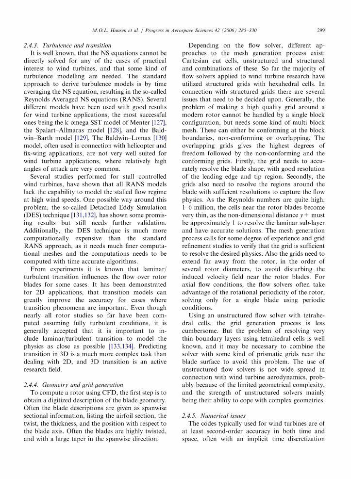
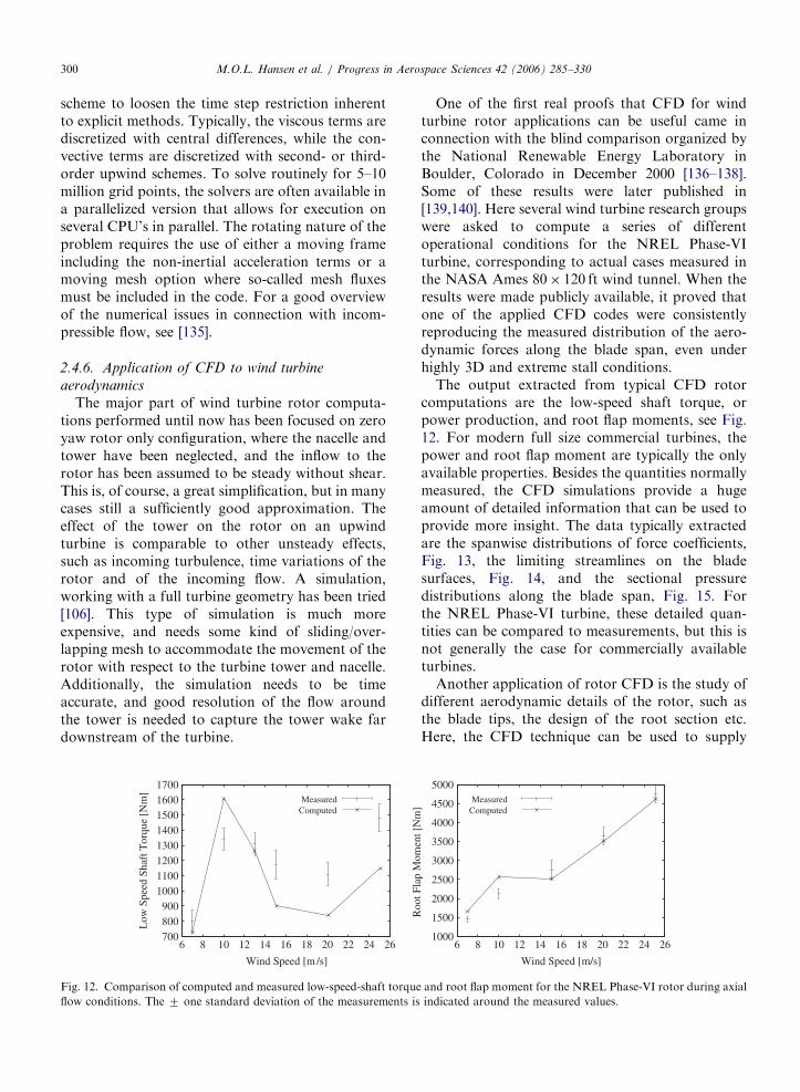
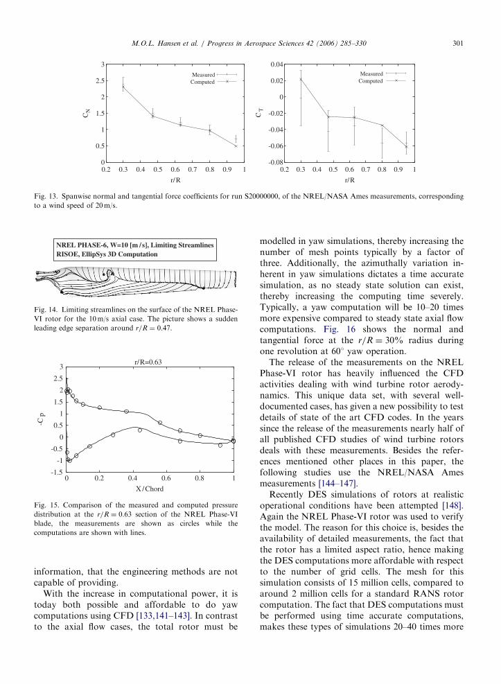
ARTICLE IN PRESS
0
05
1
15
2
25
3
02 03 04 05 06 07 08 09 1
CN
rR
MeasuredComputed
-008
-006
-004
-002
0
002
004
02 03 04 05 06 07 08 09 1
CT
rR
MeasuredComputed
Fig 13 Spanwise normal and tangential force coefficients for run S20000000 of the NRELNASA Ames measurements corresponding
to a wind speed of 20ms
NREL PHASE-6 W=10 [m s] Limiting StreamlinesRISOE EllipSys 3D Computation
Fig 14 Limiting streamlines on the surface of the NREL Phase-
VI rotor for the 10ms axial case The picture shows a sudden
leading edge separation around rR frac14 047
-15
-1
-05
0
05
1
15
2
25
3
0 02 04 06 08 1
-Cp
X Chord
rR=063
Fig 15 Comparison of the measured and computed pressure
distribution at the rR frac14 063 section of the NREL Phase-VI
blade the measurements are shown as circles while the
computations are shown with lines
MOL Hansen et al Progress in Aerospace Sciences 42 (2006) 285ndash330 301
information that the engineering methods are notcapable of providing
With the increase in computational power it istoday both possible and affordable to do yawcomputations using CFD [133141ndash143] In contrastto the axial flow cases the total rotor must be
modelled in yaw simulations thereby increasing thenumber of mesh points typically by a factor ofthree Additionally the azimuthally variation in-herent in yaw simulations dictates a time accuratesimulation as no steady state solution can existthereby increasing the computing time severelyTypically a yaw computation will be 10ndash20 timesmore expensive compared to steady state axial flowcomputations Fig 16 shows the normal andtangential force at the rR frac14 30 radius duringone revolution at 601 yaw operation
The release of the measurements on the NRELPhase-VI rotor has heavily influenced the CFDactivities dealing with wind turbine rotor aerody-namics This unique data set with several well-documented cases has given a new possibility to testdetails of state of the art CFD codes In the yearssince the release of the measurements nearly half ofall published CFD studies of wind turbine rotorsdeals with these measurements Besides the refer-ences mentioned other places in this paper thefollowing studies use the NRELNASA Amesmeasurements [144ndash147]
Recently DES simulations of rotors at realisticoperational conditions have been attempted [148]Again the NREL Phase-VI rotor was used to verifythe model The reason for this choice is besides theavailability of detailed measurements the fact thatthe rotor has a limited aspect ratio hence makingthe DES computations more affordable with respectto the number of grid cells The mesh for thissimulation consists of 15 million cells compared toaround 2 million cells for a standard RANS rotorcomputation The fact that DES computations mustbe performed using time accurate computationsmakes these types of simulations 20ndash40 times more
ARTICLE IN PRESS
-2
0
2
4
6
8
10
12
0 50 100 150 200 250 300 350
CN
Azimuth Angle [deg]
S1500600 r R=030
MeasurementsComputed
MeasurementsComputed
-04
-02
0
02
04
06
08
1
0 50 100 150 200 250 300 350
CT
Azimuth Angle [deg]
S1500600 rR=030
Fig 16 Azimuth variation of normal and tangential force coefficient for the NREL Phase-VI turbine at the rR frac14 04 section during a
601 yaw error at 15ms wind speed
MOL Hansen et al Progress in Aerospace Sciences 42 (2006) 285ndash330302
expensive than standard steady-state rotor compu-tations For modern-type rotors with large aspectratios the cell count would be even higher and thecomputations even more expensive For the NRELPhase-VI rotor the improvement using the DEStechnique is very limited but for other rotors wherethe RANS equations do not perform as well DESmay provide much more improvement The use ofpure Large Eddy Simulation has been demon-strated in [149] where a computational grid of 300million points is used to compute the initialtransient of the development of a tip vortex
247 Future
Today NS solvers are an important tool foranalysing different wind turbine rotor configura-tions and are used routinely along with measure-ments and other computational tools fordevelopment and investigation of wind turbinesNS solvers are especially well suited for detailedinvestigation of phenomena that cannot directly beaccessed by simpler and less computationallyexpensive methods Additionally NS methods canbe used as a supplement to measurements wherethey can be used both in the planning phase and tohave a better interpretation of the actual physics inconnection with the analysis of measurements
Finally one of the latest trends is to couple NSsolvers to structural codes to perform full elasticcomputations of wind turbine rotors
3 Structural modelling of a wind turbine
The main purpose of a structural model of a windturbine is to be able to determine the temporalvariation of the material loads in the variouscomponents This is accomplished by calculating
the dynamic response of the entire constructionsubject to the time-dependent load using an aero-dynamic model such as the BEM method Foroffshore wind turbines also wave loads and perhapsice loads on the bottom of the tower must beestimated Two different and frequently usedapproaches to set up a dynamic structural modelfor a wind turbine are described in the nextsubsections
31 Principle of virtual work and use of modal shape
functions
The principle of virtual work is a method to setup the correct mass matrix M stiffness matrix Kand damping matrix C for a discretized mechanicalsystem as
M euroxthorn C _xthorn Kx frac14 Fg (311)
where Fg denotes the generalized force vectorassociated with the external loads p Eq (311) isof course nothing but Newtonrsquos second law assum-ing linear stiffness and damping and the method ofvirtual work is nothing but a method that helpssetting this up for a multibody system and that isespecially suited for a chain system Knowing theloads and appropriate conditions for the velocitiesand the deformations Eq (311) can be solved forthe accelerations wherefrom the velocities anddeformations can be determined for the next timestep The number of elements in x is called thenumber of DOF and the higher this number themore computational time is needed in each time stepto solve the matrix system Use of modal shapefunctions is a tool to reduce the number of DOFand thus reduce the size of the matrices to make thecomputations faster per time step A deflection
ARTICLE IN PRESSMOL Hansen et al Progress in Aerospace Sciences 42 (2006) 285ndash330 303
shape is here described as a linear combination of afew but physical realistic basis functions which areoften the deflection shapes corresponding to thelowest eigenfrequencies (eigenmodes) For a windturbine such an approach is suited to describe thedeflection of the tower and the rotor blades and theassumption is that the combination of the PowerSpectral Density of the loads and the damping ofthe system do not excite the eigenmodes associatedwith higher frequencies In the commercially avail-able and widely used aeroelastic simulation toolFLEX see eg [150] only the first 3 or 4 (2 flapwiseand 1 or 2 edgewise) eigenmodes are used for theblades Results from this model are generally ingood agreement with measurements indicating thevalidity of the underlying assumption First one hasto decide on the DOF necessary to describe arealistic deformation of a wind turbine For instancein FLEX4 17ndash20 DOFs are used for a three bladedwind turbine with 3ndash4 DOFs per blade as describedabove 4 DOFs for the deformation of the shaft (1for torsion 2 for the hinges just before the firstbearing with associated angular stiffness to describebending and 1 for pure rotation) 1 DOF todescribe the tilt stiffness of the nacelle and finally3 DOFs for the tower (1 for torsion 1 for the firsteigenmode in the direction of the rotor normal and1 in the lateral direction)
The method of virtual work will only be brieflydescribed For a more rigorous explanation of themethod the reader is referred to textbooks ondynamics of structures The values in the vectordescribing the deformation of the construction xiare denoted the general coordinates To eachgeneralized coordinate is associated a deflectionshape ui that describes the deformation of theconstruction when only xi is different from zero andtypically has a unit value The element i in thegeneralized force corresponding to a small displace-ment in DOF number i dxi is calculated such thatthe work done by the generalized force equals thework done on the construction by the external loadson the associated deflection shape
Fgidxi frac14
ZS
p uidS (312)
where S denotes the entire system Please note thatthe generalized force can be a moment and that thedisplacement can be angular All loads must beincluded ie also gravity and inertial loads such asCoriolis centrifugal and gyroscopic loads The non-linear centrifugal stiffening can be modelled as
equivalent loads calculated from the local centrifu-gal force and the actual deflection shape as shown in[151] The elements in the mass matrix mij can beevaluated as the generalized force from the inertialoads from an unit acceleration of DOF j for a unitdisplacement of DOF i The elements in the stiffnessmatrix kij correspond to the generalized force froman external force field which keeps the system inequilibrium for a unit displacement in DOF j andwhich then is displaced xi frac14 dij where dij isKroneckers delta The elements in the dampingmatrix can be found similarly For a chain systemthe method of virtual work as described herenormally gives a full mass matrix and diagonalmatrices for the stiffness and damping For oneblade rigidly clamped at the root (cantilever beam)it is relatively easy to estimate the lowest eigen-modes (first flapwise u1f(x) first edgewise u1e(x) andsecond flapwise u2f(x)) eg using an iterative methodas described in [151] The eigenmodes are normallydescribed in a coordinate system aligned with the tipchord as eg shown in Fig 1 It is practical tonormalize the deflection shapes so that the tipdeflection is unity It is now assumed that anydeflection can be described as a linear combinationof these modes as
uethxTHORN frac14 x1u1f ethxTHORN thorn x2u
1eethxTHORN thorn x3u2f ethxTHORN (313)
The velocity and accelerations can be calculatedrespectively as
_uethxTHORN frac14 _x1u1f ethxTHORN thorn _x2u
1eethxTHORN thorn _x3u2f ethxTHORN (314)
and
eurouethxTHORN frac14 eurox1u1f ethxTHORN thorn eurox2u
1eethxTHORN thorn eurox3u2f ethxTHORN (315)
The advantage of the method using generalizedcoordinates and modal shape functions is that thenumber of DOF in the dynamic system can bereduced to a relatively small number Further somehigh eigenfrequencies are filtered away which isbeneficial for the allowable time step when comput-ing deformations xnthorn1
i and velocities _xnthorn1i at time
t frac14 (n+1)Dt from deformations xni velocities _xn
i and accelerations euroxn
i at time t frac14 nDt A goodchoice for the time integration scheme is theRungendashKuttandashNystrom method which requiresfor stability reasons that the time step shouldresolve the highest eigenfrequency with 4 pointsbut for accuracy reasons 10 points is preferredBy reducing the highest eigenfrequency using amodal description of eg the blades not only
ARTICLE IN PRESSMOL Hansen et al Progress in Aerospace Sciences 42 (2006) 285ndash330304
reduces the number of DOFs but also larger timesteps can be taken
32 FEM modelling of wind turbine components
applying non-linear beam theory
Even though modal analysis offers a computa-tionally effective way to analyse wind turbinedynamics most of the recently developed aeroelasticcodes use a full FEM approach [152] which allowsa more complex deformation state of the windturbine The main features of such modellingprocedures together with some aspects of non-linearbeam theory are discussed in the present section
The structural modelling of wind turbines isbased on beam theory For a 1D structure (beam)subjected to bending in two directions torsion andaxial tension the formulation of the problemconsists of two parts (a) the elastic model whichreduces the 3D structure of each component into a1D structure concentrated along the elastic axis ofthe beam and (b) the derivation of the dynamicequations In classical beam theory (first order) thedeformed position r of any point initially at x0 frac14ethx y zTHORNT (Fig 17) can be described by the displace-ment vector u frac14 fu vw ygT consisted of the two
Undeformed geometry
x
z
u
wr
zF +
Mx
Fx
Mz
FzMy
Fy
x
z
(a)
a
b
Fig 17 Kinematics and dynam
bending displacements u w the torsion angle y andthe tension v
r frac14 n0 thorn S0 uthorn S1 yu
S0 frac14
1 0 0 z
0 1 0 0
0 0 1 x
264
375
S1 frac14
0 0 0 0
x 0 z 0
0 0 0 0
264
375
(321)
Using Hookersquos law and assuming that shear stressesdo not produce net torsion the sectional elasticloads can be derived
Fy frac14 ethEATHORNqyv ethEAxTHORNq2yyu ethEAzTHORNq2yyw
My frac14 ethGItTHORNqyy
Mx frac14 ethEIxzTHORNq2yyuthorn ethEIxxTHORNq
2yyw ethEAzTHORNqyv
Mz frac14 ethEIzzTHORNq2yyu ethEIxzTHORNq
2yywthorn ethEAxTHORNqyv
eth322THORN
where the terms in parentheses denote the averagedsectional properties of the structure By consideringthe balance of loads and moments on of a beam
Deformed geometrydy
y
A
u+du
w+dwDeformed elastic axis
M + dMz
z
z
M + dMyy
M + dMxx
dF
yyF + dF
xxF + dFdr
ra
δPy
A(b)
ics of a beam structure
ARTICLE IN PRESS
x
z
yu
w
vO
Orsquoz
xz
xu
w θtθ
ζ
ξ
ξ
θθ
θ +ˆ
Fig 18 Beam co-ordinate system definition
MOL Hansen et al Progress in Aerospace Sciences 42 (2006) 285ndash330 305
element of length dy the beam equations arederivedZ
A
eurordm
dy frac14 dFthorn
ZA
g dm
dythorn dpdy
(323)
ZA
r0 eurordm
dy frac14 dMthorn dr ethFthorn dFTHORN
thorn
ZA
r0 gdm
dythorn ra dpdy eth324THORN
where m denotes the mass per unit length dF dMare the net elastic loads on dy g is the accelerationof gravity and dp the sectional aerodynamic loadsexerted at the aerodynamic centre ra frac14 ethxa 0 zaTHORNwhile
r0 frac14 fduthorn xthorn zy dvthorn dydwthorn z xygT
ffi fxthorn zy dy z xygT
In view of a more systematic and general frameworkfor formulating dynamic equations Hamiltonrsquosprinciple has been also used [153154]
By introducing (322) into (323) and (324) thebeam dynamic equations are obtainedZ
A
ethS0THORNT euror dm qy
ZA
ethS1THORNT euror dm frac14 qyfrac12K11 qyu
thorn q2yyfrac12K22 q2yyu thorn qyfrac12K12 q
2yyu
thorn q2yyfrac12K21 qyu thorn
ZA
ethS0THORNT g dmthorn Sa dP
eth325THORN
K11 frac14
Fy 0 0 0
0 EA 0 0
0 0 Fy 0
0 0 0 GIt
2666664
3777775
K22 frac14
EIzz 0 EIxz 0
0 0 0 0
EIxz 0 EIxx 0
0 0 0 0
2666664
3777775
Sa frac14
1 0 0
0 1 0
0 0 1
za 0 xa
2666664
3777775
K12 frac14
0 0 0 0
EAx 0 EAz 0
0 0 0 0
0 0 0 0
2666664
3777775
K21 frac14
0 EAx 0 0
0 0 0 0
0 EAz 0 0
0 0 0 0
2666664
3777775
In case of flexible blades if large deformations areexpected as in the case of helicopter blades second-order non-linear beam theory is to be used Therelevant developments originate from the work in[154] The beam axis again lies along the y-axis butin the undeformed state of the beam while x and z
denote the two bending directions of the beam Atits deformed state a local co-ordinate system O0xZzis introduced which follows the pre-twist of thebeam so that x and z coincide with the localstructural principle axes of the cross section(Fig 18)
Then (321) becomes
r frac14
u
ythorn v
w
8gtltgt
9gt=gtthorn E
x
lyy
z
8gtltgt
9gt=gt (326)
where l denotes the warping function of the crosssection and E is the transformation matrix betweenOxyz and O0xZz In [154] E is given in terms of theelastic displacements up to second order Next thestrain tensor ij defined through (326) is introducedin Hookersquos law in order to define the strainndashdispla-cements relations which are used in the derivationof the resulting sectional elastic loads as in (322)Because they are derived in the O0xZz system beforeintroducing them in (323) and (324) they aretransformed into the Oxyz system using the
ARTICLE IN PRESS
ρk
rGk
OG O
xG x
zG z
yG
y y
z
x
O
x
y
z
O
Fig 19 Multi-body representation of a wind turbine
MOL Hansen et al Progress in Aerospace Sciences 42 (2006) 285ndash330306
transformation matrix E The final expressions arequite lengthy and the reader is referred to [154] It isnoted that compared to the classical beam modelsecond-order theory will produce fully completestiffness matrices containing many non-linear termsThe above non-linear beam model is a specificexample amongst several models of varying com-plexity which have been gradually developed start-ing from the Timoshenko beam theory byeliminating the ad hoc simplifying assumptions ofthe original model [155ndash158]
Regarding wind turbines almost all structuralmodels are based on classical beam theory[150153159ndash162] This is partially due to the factthat wind turbine components are far more rigidcompared to helicopter blades for which non-lineartheory has been developed Furthermore most of thedifficulties in analysing wind turbine systems aregenerated by the aerodynamics and in particular theonset of stall which is certainly less pronounced onhelicopter rotors Current designs are quite stiff sothat non-linear beam modelling is not expected tochange drastically the quality of predictions besidesproviding a sound basis for including the geometricalnon-linearities [163] However if wind turbinesbecome more flexible it could become necessary toadopt such kind of structural modelling
Regardless the details the beam equations arefourth order with respect to bending and secondorder with respect to tension and torsion So for aFE approximation of the equations C1 shapefunctions are used for uw and C0 for v and y Atthe element level uw are approximated with third-order polynomials and the DOFs are the values andspace derivatives at the end nodes while v and y areapproximated with first-order polynomials and theDOFs again at the end nodes In some models andcertainly when the second-order beam theory isapplied second- and third-order polynomials areused respectively for v and y In this case the mid-point as well the points at 13 and 23 interior pointsare used as nodes So within an element lsquolsquoersquorsquo
ueethy tTHORN frac14 NeethyTHORN ueethtTHORN (327)
where NeethyTHORN is the matrix containing the shapefunctions and ueethtTHORN the vector of the DOFs at thenodes of the elements [164] As in Section 31concerning the principle of virtual work which inthe FEM terminology is the Galerkin formulationof the problem is used to generate the discreteequations With reference to (325) taken symboli-cally as Zethu _u eurouTHORN frac14 0 for any admissible virtual
displacement field du we require that
Z L
0
duT Zethu _u eurouTHORNdy
X
e
Z Le
0
duTe Zethue _ue euroueTHORNdy frac14 0 8du eth328THORN
Because dueethy tTHORN frac14 NeethyTHORN dueethtTHORN it follows that
Xe
Z Le
0
NeT ZethNeueNe _ueN
e euroueTHORNdy frac14 0 (329)
which is a set of second-order ordinary equations intime with respect to ueethtTHORN Although Z can containnon-linear terms it can always be written in theusual form
MethuTHORN eurouthorn Cethu
THORN _uthorn Kethu
THORN u frac14 Qethu
THORN (3210)
where the mass damping and stiffness matrices aswell as the generalized loads in the RHS in generalwill depend on the displacement field and its timeand space derivatives (noted by a tilde)
ARTICLE IN PRESS
y
O
q8 q9 q10 q11q12 q13
yG y
z
x
O
x
y
z
OG O
xG x
zG z
q1 q2 q3 q4q5 q6
q7
q14
Fig 20 A typical definition of the q DOF on a HAWT
MOL Hansen et al Progress in Aerospace Sciences 42 (2006) 285ndash330 307
The main components of a wind turbine are theblades the drive-train and the tower (Fig 19) Theyare all modelled as beam structures and typically thestructural properties are assumed for each compo-nent to continuously vary along the correspondingelastic axis However localized properties can beadded in the form of concentrated masses dampersor springs The gearbox (if present) the generatorthe hub are usually added in this way Otherexamples are the flexibility or damping character-istics of the yaw bearing or the pitch mechanismThe involvement of different body motions for eachcomponent in combination with the connectionswhere loads and displacements are communicatedfrom one component to the other calls for a globalformulation of the dynamic problem To this endmost works adopt a multi-body approach [165]which consists of considering each componentseparately subjected to appropriate boundary con-ditions which fit the different components into thecomplete configuration In such an approach theelastic DOF of each component are defined as localelastic displacements to which rigid body motionsare added through the kinematic boundary condi-tions see eg [161166167] for a more generaldiscussion It is also possible to introduce the globaldisplacements and rotations at each node instead ofthe local ones [153] allowing a unified description ofthe complete configuration In this case howeverthe non-linearities of the connections are introducedimplicitly and therefore linearization can only beperformed globally which is not always desirable
In multi-body modelling each component k isassigned a local coordinate system Oxyz with itsundeformed elastic axis along the y-axis Then theposition of a point with respect to the fixed systemrGk can be expressed with respect to its localposition rk (defined as in (321)) as follows
rGk frac14 qk thorn Ak rk (3211)
where qk denotes the position of the origin of thelocal system with respect to the fixed system and Ak
denotes the local to global transformation matrixThe exact form of qk and Ak depends on thekinematic conditions introduced when joining (con-necting) the various components (ie blades-to-hubor drive-train-to-tower) Depending on the type ofconnection common global displacements androtations are assigned for the restricted DOF whichare identified to either an existing elastic DOF (shaftbending at the hub) or a rigid body motion (bladepitch) The component contributing the kinematics
will in response receive from the rest of theconnected components their internal (or reaction)loads This operation involves co-ordinate systemtransformations between the components The setof kinematical DOF involved in the definition of qk
and Ak for all components is denoted collectively asq So qk frac14 qk(q t) and Ak frac14 Ak(q t) qk is defined asa mixed series of translations and rotations whereasAk is defined solely as a sequence of rotations Atypical example is shown in Fig 20 where q1ndashq6 arethe elastic DOF at the top of the tower q8ndashq13 arethe elastic DOF of the drive train at the hub and q7and q14 are the yaw angle and the pitch of the bladerespectively By introducing (3211) into (325) thecentrifugal and Coriolis terms of the inertia loadsappear as a result of the time derivatives of Ak whilein the Hamiltonrsquos principle approach they areproduced automatically
By combining the equations of all componentsthe complete system of the dynamic equations forthe wind turbine is obtained in the form of (3210)with respect to an extended vector of DOFuext frac14 u q
By construction qk and Ak will depend
on unknown DOF while at the same time theycorrelate the state of the components in contact sothe terms they generate are non-linear with respectto the unknown DOF uk and q Linearization in thiscase is a tedious procedure which must be donecarefully and systematically Fortunately softwareusing symbolic mathematics such as Mathematica
ARTICLE IN PRESSMOL Hansen et al Progress in Aerospace Sciences 42 (2006) 285ndash330308
are available which are strongly recommended Theprocedure is based on Taylorrsquos expansions of allvariables and retaining of first-order terms Alter-natively the extended version of (3210) can besolved directly through an iterative procedure ineach time step which can use the linearized solutionas a starting predictor
4 Problems and solutions in wind turbine
aeroelasticity
In the following section the use of aeroelasticcodes on wind turbine constructions includingstability studies will be illuminated mainly throughexamples
41 Aeroelastic stability
Wind turbines suffer from low structural damp-ing which can become critical under certain opera-tional conditions Most problems appear on theblades that receive almost 100 of the loading Inparticular the onset of stall plays a decisive role notonly on stall-regulated machines but also on pitch-regulated ones around rated conditions On theother hand the blades are made of compositematerials for which the knowledge on damping issubstantially inferior compared to steel or concreteconstructions The damping of composite structuresdepends on the ambient temperature So dependingon the season or the time during the day thestructural damping of the blades can decreasesubstantially Furthermore aging always degradesthe damping of composite structures There is adefinite need to increase structural damping andsignificant effort has been put recently on itsmodelling in composite structures as well as in theirappropriate design This is one direction of researchregarding the improvement of the stability char-acteristics of modern wind turbines see [168] for areview of the current developments Damping isrequired to suppress the onset of vibrationsgenerated by the unsteady aerodynamic loads thatinteract with the wind turbine structure First theaeroelastic modelling of wind turbines is consideredand then on this basis the aeroelastic stabilityproblem is formulated and the relevant availablemethods are reviewed
Aerodynamic modelling involves the calculationof the aerodynamic loads that also depend on thedynamics of the system The flap and lag vibrationsare interpreted by the incoming flow as a change in
the effective angle of attack indicating strongaeroelastic coupling All the currently availableaeroelastic tools for wind turbines use 2D dynamicairfoil data models such as the BeddoesndashLeishmannor the ONERA model They provide aerodynamiccoefficients as functions of the aerodynamic statevariables that satisfy appropriate dynamic equa-tions [17169] In either model the equations are 2Dand so they are applied on a strip-by-strip basismeaning that there is no interaction in the radialdirection This fits well with BEM modelling of theoverall aerodynamic analysis In fact the followingpresentation is referred to the BEM context sincemost existing stability models are based on it If apotential flow model is applied then the attachedpart of lift can be associated to potential lift whilethe rest is simply added [163] If the potential flowmodel is enhanced with a separation model thereshould be correlation on both aspects [58] How-ever the latter has not been applied yet inaeroelastic computations
By considering a blade section at a radial positionas shown in Fig 1 the local aerodynamic loadsacting on this section of the blade can be written asfollows since the lift is perpendicular and the dragparallel to the relative wind
py frac14 L sin fD cos f
pz frac14 L cos fthornD sin f
My frac14M eth411THORN
where L D are the lift and drag forces M is thepitching moment f is the local flow angle withrespect to the rotor plane Once the induced velocityhas been determined the local effective incidence aand relative flow velocity can be calculated as shownin Section 21 They will depend on the elasticdeformations and the velocities the rigid bodymotions and if appropriate orientation changes asin pitch and yaw variations In order to obtain aunified description of the coupled aeroelasticproblem a so-called aeroelastic finite element isdefined [170] which in addition to the elastic DOFthe aerodynamic state variables added For examplein the ONERA model there will be in total eightadditional DOF Because the dynamic equations forthe aerodynamic state variables only can be firstorder in time in order to produce a consistentcoupled system they can be differentiated as in[171] Therefore they can be assembled togetherwith the dynamic equations in the form of (3210)where the vector of the unknowns is further
ARTICLE IN PRESSMOL Hansen et al Progress in Aerospace Sciences 42 (2006) 285ndash330 309
extended to include the additional aerodynamicDOF Another approach used in [172] is tointroduce the modal expansion of the structuralDOF at stand still which better conditions thecoupled system
On the above basis it is possible to formulate theaeroelastic stability problem for wind turbinesWithin the context of linear theory stabilityboundaries are obtained by examining the evo-lution of small perturbations with respect to asteady state or a periodic solution acting asreference To this end the original equations arelinearized with respect to the reference state andthe resulting system solved with respect to thefluctuations
Methuref THORN eurouthorn Cethuref THORN _uthorn Kethuref THORN u frac14 Q (412)
where M C and K depend only on the referencesolution If the matrices do not depend on time(412) is reformulated into a first-order system
_y frac14 D ythorn b y frac14 u _un oT
(413)
The eigenvalue analysis of D provides the eigen-frequencies and damping of the system [173] This ispossible when the reference state corresponds to asteady solution as in the case of an isolated bladeHowever when analysing the complete windturbine configuration due to the rotation of theblades the reference state should correspond to aperiodic equilibrium state with reference to the rotorspeed which is assumed constant In this case thecorresponding theoretical framework is Floquetrsquostheory which for a large system is computationallyheavy [174] If the blades are identical and thenumber of blades NX3 which is the most frequentcase it is possible by means of multi-bladetransformation to eliminate the periodic coefficientsin the coefficients of (412) and therefore be ableto still use eigenvalue analysis [175] In this contextthe non-linear equations of the system are inte-grated in time until such a periodic state is attainedIn the case of an unstable situation because thetime domain response will contain significantcomponents in all of the basic eigenfrequencies ofthe system the reference state is obtained bytruncating the response so as to retain only its 1and Nrev components To this end all DOF in therotating system qm m frac14 1 NX3 are reformedqm frac14 q0 thorn qc cos cm thorn qs sin cm where cm frac14 Otthorn
eth2p=NTHORNethm 1THORN is the corresponding azimuth loca-tion Next the equations for the blade DOFs are
rearranged by applying the operators eth1=NTHORNPN
mfrac141
eth THORN eth2=NTHORNPN
mfrac141eth THORN cos cm and eth2=NTHORNPN
mfrac141eth THORN
sin cm This is performed after the periodic solutionhas been obtained over one period of rotation Theresulting equations will be in the non-rotating frameand contain only higher harmonics (3rev andhigher) By averaging over one period the finalconstant coefficient system is obtained in the formof (413) For the blades y will contain thecorresponding q0 qc and qs DOF and their timederivatives for both the purely structural and theaerodynamic DOF [171] In the above approach it isworth noticing that the averaging procedure willforce the reference state to appear in the equationsThis is an important aspect when dealing with non-linear systems
Stability of wind turbines has been consideredsystematically in Europe in the late 1990s [176] whiletoday there is an on-going activity under the EUfunded project STABCON Several linear stabilitytools have been produced along the lines describedabove and good correlation has been obtainedamongst the different codes see [177] and thereferences cited Inevitably linear theory is approx-imate so the results it produces are subject to crosschecking Clearly flutter measurements are difficultto obtain because of the involved risk therefore it isindispensable to rely on theoretical developmentswhich will be discussed in the next section
42 Aeroelastic coupling linear vs non-linear
formulations
Linearization of the aeroelastic equations cer-tainly offers computational efficiency However it isnot always appropriate For the structure lineartheory requires that the deformations and displace-ments are small an assumption not always validFor the aerodynamics and its coupling with thestructure linearization will suppress some depen-dencies involved in (411) and therefore influencethe estimation of the aerodynamic damping In thisconnection the use of semi-empirical unsteadyaerodynamic models introduces still unresolveduncertainties Furthermore there are cases in whichthe multi-blade transformation is not applicable egwhen blades are non-identical or when the rota-tional speed varies
Retaining fully the non-linearities of the aero-elastic problem has the following consequences thestructure is considered at its deformed state thecoupling conditions among the components are
ARTICLE IN PRESSMOL Hansen et al Progress in Aerospace Sciences 42 (2006) 285ndash330310
taken in their full form and the aerodynamicequations are not simplified The last point isimportant with respect to the best possible estima-tion of the aerodynamic damping within themargins offered by the semi-empirical models usedin the currently available aeroelastic tools In thisrespect multi-body analysis which has beenadopted in most of the existing stability tools[161178ndash181] offers this option by constructionprovided that the structural model considers theconstruction at its deformed state and the codetakes this into account in the definition of the localaerodynamics
Under such conditions the information of thestability characteristics of the wind turbine arecontained in the time signals of the loads calculatedthrough a non-linear time domain simulation Thereexist two types of methodologies for retrieving thisinformation the one is based on the work-basedapproach [176] while the other is using signal-processing techniques In the work-based methodany mode shape is excited and loads are recordeduntil a steady periodic state has been reached Thenthe aerodynamic damping is estimated by the workof the aerodynamic loads over the last period underthe assumption that there is no energy interchangebetween the modes through the aerodynamic loadsIn the signal processing approach the system isharmonically excited for a finite duration Then thetransient response following the abrupt terminationof the excitation is recorded wherefrom the aero-elastic damping and frequency of the specific modeare determined There are two different methodsboth well documented in the literature [182ndash184]that can be used the moving block method and themethod of Hilbert transform The moving blockmethod is a FFT based method commonly used inrotorcraft applications [182184] The transientresponse amplitude is computed on a block of datausing a FFT calculation The block is then movedforward by a single point in time and the computa-tion of the transient response amplitude is repeatedThe linear fit for the slope of the natural logarithmof the sequence of response amplitudes in time(peak plot) provides the damping (Fig 21) In theHilbert method the transient response y(t) and itsHilbert transform ~yethtTHORN are used to define theenvelope signal AethtTHORN frac14
ffiffiffiffiffiffiffiffiffiffiffiffiffiffiffiffiffiffiffiffiffiffiffiffiffiy2ethtTHORN thorn ~y2ethtTHORN
p[183184]
For a transient response typical of a viscouslydamped system a line can be fitted to the logarithmof this envelope The slope of this line as in the caseof the moving block method gives the damping
(Fig 22) Comparing the two it has been found thatthe Hilbert method has certain advantages over themoving block method In particular the Hilbertdamping analysis provides an estimate of thedecaying envelope signal so it can be used inassessing the non-linear damping characteristics ofa mode Therefore it is not limited by the assump-tion of the viscous damping as the moving blockmethod does Moreover experience has shown thatthe Hilbert method is more efficient in calculatingthe damping of spectrally close modes [163]
43 Examples of time simulations and instabilities
In this section the challenges in aeroelastic design ofwind turbine rotors will be addressed and in particularthe phenomenon of aeroelastic instability of windturbine rotors will be explored by showing examplesof simulation results on a wind turbine design
Back from the beginning of development ofmodern wind turbine rotors in the late seventiesthere has been concern about the problems thatcould arise due to aeroelastic instability In parti-cular the use of the stall regulation principle wasuncertain as it was foreseen that a flapwiseinstability (so-called stall flutter) would occur whenoperating in the stall region due to the negativeslope of the CL vs a curve However it turned outthat the flapwise instability during operation in stallwas not the most critical problem but instead theedgewise instability resulting in edgewise bladevibrations The first experimental evidence of thisinstability was seen in the mid nineties and initiatedconsiderable research activities in order to explorethe phenomenon and provide practical solutionsBelow is mainly focused on this instability as thisserves as a good example to illustrate the problem ofaeroelastic instability in more general terms
In the more recent wind turbine designs theregulation of the turbines has shifted from stallregulation to pitch control where the operationalrange for the flow over the blade moves to low angleof attack at high wind and thus away from the stallregion This has almost removed the instabilityassociated with stall during operation but it is stillso that the edgewise blade modes are aerodynami-cally low damped on the pitch regulated turbines
A major instability problem on the modernturbines is seen when the rotor is parked or idlingat very low RPMs at wind speeds above stop windspeed which typically is around 25ms Again it istypically edgewise dominated instability problems
ARTICLE IN PRESS
3540
4550
tim
e (s
ec)
-35
E+
06
-3E
+06
-25
E+
06
-2E
+06
-15
E+
06
-1E
+06
tower top tilt bending moment (Nm)
12
34
freq
uenc
y (H
z)
0
5E+
08
1E+
08
15E
+08
2E+
08
25E
+08
3E+
08
FFT of the tower top tilt bending moment (Nm)
Δt
data
19
190
5
191
191
5
192
192
5
193
193
5
194
00
51
15
22
53
t (se
c)
-ζ Ω
n
log of response amplitude
Fig21Schem
aticdescriptionofthemovingblock
dampinganalysis
MOL Hansen et al Progress in Aerospace Sciences 42 (2006) 285ndash330 311
ARTICLE IN PRESS
-15e+06
-1e+06
-500000
0
500000
1e+06
15e+06
2 4 6 8 10 12 14
tow
er to
p til
t ben
ding
mom
ent (
KN
m)
time (s)
transient signalenvelope signal
envelope signal exp fit
Fig 22 Envelope signal calculation of the tower top tilting moment transient response using the Hilbert transform method for the same
signal as in Fig 21
1000
800
600
400
200
0
-2000 50 100 150 200 250 300
Time [sec] Time [sec]
ED
GE
WIS
E B
LA
DE
RO
OT
MO
ME
NT
[U
NC
AL
IBR
AT
ED
]
ED
GE
WIS
E B
LA
DE
RO
OT
MO
ME
NT
[U
NC
AL
IBR
AT
ED
]
EDGEWISE BLADE VIBRATION INSTABILITY EDGEWISE BLADE VIBRATION INSTABILITY--MEASUREMENT
1000900800700600500400300200100
0-100
200 210 220 230 240 250 260
Fig 23 Measured edgewise blade root moment on a stall regulated rotor at high wind Detail of the time track to the right
MOL Hansen et al Progress in Aerospace Sciences 42 (2006) 285ndash330312
related to stall of the blade A simulation examplewill be shown later to illustrate this problem
Finally the flutter instability will be addressed Itseems that the increased up scaling of the turbineshas led to rotor and blade designs where the flutterspeed is not so far away from normal operationalspeed Also this instability will shortly be illustrated
431 Edgewise blade vibration instability
As mentioned above the first experimentalevidence of this instability was seen in the mid
nineties on stall-regulated rotors with a diameter of35ndash40m An example is presented in Fig 23 and it isseen that the amplitude of the edgewise blade rootmoment (which at steady conditions vary sinusoidalwith 1p due to the gravity) increases 2ndash3 times dueto instability during operation in stall The experi-mental evidence of the edgewise instability led toconsiderable research on this subject and a majorEuropean project lsquolsquoPrediction of Dynamic Loadsand Induced Vibrations in Stallrsquorsquo funded by the EUwas carried out in the period from 1995ndash1998 [176]
ARTICLE IN PRESSMOL Hansen et al Progress in Aerospace Sciences 42 (2006) 285ndash330 313
The origin of the instability is simple If a rotatingairfoil section is harmonically translated along anaxis xB and the direction of this axis yRB relative tothe orientation xR of the rotor plane is varied theaerodynamic damping coefficient for the sectionvaries considerably see Fig 24 from [185] For lowyRB which means in-plane or edgewise vibrationdirection the damping coefficient is negative even atlow wind speed For vibrational directions close to901 which corresponds to out-of-plane or flapwisedirection the damping coefficient is strongly depen-dent on the inflow wind speed It is highly damped
Fig 24 The aerodynamic damping coefficient c_xx_b for a rotating a
different inflow velocities from [185]
Fig 25 Damping characteristics computed for a rotating isolated bl
at low wind but close to zero or negative damped athigh wind
On a complete rotating blade the direction ofvibration depends on the structural design of theblade as well as of the complete turbine structureThe movement of the tip section of the blade willnow no longer necessarily be along a straight lineHowever typically the tip section of the blade in thefirst flapwise mode will be on a path almostperpendicular to the rotor plane and in the 1stedgewise mode it will almost be in-plane It is thusexpected that the basic damping characteristics of
irfoil section as function of vibration direction yRB and at three
ade using the linear aeroelastic stability tool HAWCStab [186]
ARTICLE IN PRESSMOL Hansen et al Progress in Aerospace Sciences 42 (2006) 285ndash330314
the whole blade will be comparable with thecharacteristics of a single airfoil section Using thelinear stability tool HAWCStab the dampingcharacteristics for a rotating blade can easily bederived and the computed damping characteristicsfor a rotating 19m blade (500 kW rotor) corre-sponding to the blades of the rotor where theexperimental instability was shown in Fig 23 areshown in Fig 25 from [186] It is seen that thedamping for the first flapwise mode varies fromhighly positive values at low wind speed and tovalues close to zero at 14ms and then increasingslightly at higher wind speeds It should be notedthat the influence of using unsteady blade sectionaerodynamics is shown (modelled with the BeddoesLeishman model in the present case) and that thishas considerable influence on the aeroelastic damp-ing Generally the unsteady aerodynamic effectsincrease the damping The damping for the firstedgewise mode is seen to decrease gradually withincreasing wind from being slightly positive at lowwind to slightly negative at high wind Finally itshould also be noted that the damping shown is thetotal damping including the structural dampingwhich in the present case is around 2 for the firstflapwise mode and 3 for the first edgewise mode
The final step in model complexity is nowobtained by going to a full aeroelastic model ofthe turbine comprising the dynamics of the shaftthe nacelle and the tower The aeroelastic stability
Fig 26 Aeroelastic damping computed with the aeroelastic stability HA
speed
results using HAWCStab is for the complete windturbine see eg Fig 26 from [186] showing theaeroelastic damping for the first 10 mode shapes(numbered from lowest frequency) It is seen thattwo mode shapes are negatively damped at highwind speed and that one mode shape is close to zeroand slightly negatively damped at the highest windspeed For comparison time simulations with theaeroelastic code HAWC [187188] is performed onexactly the same turbine model at a wind speed of 8and 16ms respectively in order to see if theinstability at high wind speed predicted by the linearstability tool can be confirmed by the HAWCmodel with non-linear aerodynamics The com-puted edgewise blade root moment shown in Fig 27confirm the instability at high wind and comparesvery well with the measured instability shown inFig 23 It is thus demonstrated that the edgewiseinstability problem can be predicted in both timesimulations and using linearized stability analysisHowever as will be demonstrated below theedgewise vibration instability is much more complexthan just edgewise vibrations of the individualblades but comprises the dynamic characteristicsof the whole turbine This understanding is vital forthe development of design solutions preventing theinstabilities
In order to analyse the instability in more detailsthe use of parallel aeroelastic time simulations on aturbine with a stiff structure is made In this case the
WCStab [186] Three modes have negative damping at high wind
ARTICLE IN PRESSMOL Hansen et al Progress in Aerospace Sciences 42 (2006) 285ndash330 315
loads on the different components will mainlyreflect the direct load input from the externalaerodynamic forces and from gravity forces Itshould be mentioned that the simulations areperformed at two average wind speeds of 8 and16ms respectively and with a turbulence intensityof 12
A power spectral density analysis of the simulatededgewise blade root moment shows a distinct peakat 307Hz which is close to the frequency of the firstedgewise mode for a single rotating blade which is319Hz see Fig 28 The response at 16ms of theflexible turbine at this frequency is seen to be severalorders of magnitude bigger than the response of thestiff turbine indicating an instability situationSomewhat the same tendency is seen at 8ms but
Fig 28 Comparison of power spectra of edgewise blade root momen
Fig 27 Time simulation with the aeroelastic code HAWC on a 50
with considerable less difference between the re-sponse of the stiff and flexible turbine indicating lowdamping but not an instability
Analysing further the results of the stabilityanalysis with HAWCStab as shown in Fig 26 itcan be derived from the results of the model that thethree mode shapes that are negatively damped orvery low damped at 16ms are
t fo
0 k
mode no 1 with frequency 077Hz and damping605
mode no 3 with frequency 093Hz and damping433
mode no 7 with frequency 273Hz and damping
159
r a flexible and a stiff turbine respectively at 8 and 16ms
W stall regulated rotor at two wind speeds 8 and 16ms
ARTICLE IN PRESSMOL Hansen et al Progress in Aerospace Sciences 42 (2006) 285ndash330316
The numbering in HAWCStab of the modes iswith increasing mode number with increasingfrequency starting with the lowest frequency Modeno 1 and no 3 are both modes where lateral towerbending is the main motion together with edgewisebending of the three blades and torsion of the mainaxis The edgewise movement of the blades are all inphase and the difference between the two modes isthe direction of the edgewise bending relative to thetower bending Comparing again the results of thelinear stability analysis with the time simulationresults the instability of the lateral tower bendingdominated modes is confirmed by the spectra of thetower top and tower bottom lateral bendingmoments Figs 29 and 30 A distinct peak at
Fig 29 Comparison of power spectra of tower top lateral moment
Fig 30 Comparison of power spectra of tower bottom lateral mome
079Hz is seen in both tower top and tower bottomspectra at 16ms and this peak cover probably alsoa considerable content at the 093Hz which was thefrequency of mode no 3
It can be noticed that the HAWCStab results donot contain an unstable mode with a frequencyaround 307Hz (the edgewise instability) as seen inthe time simulation results However mode no 7 isin fact the response on the non-rotating turbinestructure from the edgewise vibrations at 307HzThe edgewise vibrations in the present case is a so-called backward whirling edgewise mode wherethere is a phase shift of 1201 between the movementof the blades This whirling mode results in shaftand tower bending but with a frequency shifted 1p
for a flexible and a stiff turbine respectively at 8 and 16ms
nt for a flexible and a stiff turbine respectively at 8 and 16ms
ARTICLE IN PRESSMOL Hansen et al Progress in Aerospace Sciences 42 (2006) 285ndash330 317
(p is the rotational frequency) up and downrespectively compared with the frequency in therotating system As 1p in the present case is 045Hza peak in the spectra of tower bending at afrequency of around 307ndash045Hz equal to 262Hzis expected which is also seen in Figs 28 and 29However in the HAWCStab results a slightlyhigher frequency 273Hz was seen for this mode
The presented example of the edgewise bladevibration instability has shown that the low aero-dynamic damping of an airfoil section undergoing amotion along a path close to the chordwise directioncan cause instability of quite different modes on theturbine at the same time The design challenges withthe objective to minimize the influence of lowaerodynamic damping or instability are thus big aseg changes in tower design could lead to egedgewise vibrations on the rotor A number ofdifferent methods to reduce the risk for edgewisevibrations on stall-regulated turbines have beeninvestigated [176186] and comprises eg changes ofthe stalling characteristics of the airfoils by so-calledlsquolsquostall stripsrsquorsquo as well as structural design of theblades to achieve optimal vibrational directions
432 Instability problems of parked rotors
The turbines are normally designed to operate upto a certain maximum wind speed and above thiswind speed the turbines are shut down In thestopped conditions the rotors can be completelyparked or they can idle with low rotational speeddepending on the actual design of the controlsystem As part of the certification of the turbineit must be shown that the turbine can withstand the
Fig 31 Simulation of a parked rotor at 50ms and a yaw error of 601
power spectrum of the same signal to the right
wind loads at extreme wind speed conditions withparked rotor and the wind coming from anydirection in the case that the yawing system of theturbine is not functioning
As an example the simulation of a rotor parkedat a wind speed of 50ms and a yaw error of 601 isshown in Fig 31 The turbine is the same as aboveand the time track of the edgewise blade rootmoment indicates low damping as the amplitudesvary much in time To the right in Fig 31 is shown apower spectrum of the same signal and it shows thatthe blade mainly vibrates in two modes mode 3 at afrequency of 093Hz which was described aboveand the first edgewise blade frequency at about319Hz For the present inflow direction thevibrations are not unstable but it has to bedocumented for all inflow directions
433 Flutter instability
The last example of an instability is flutter This isa well-known instability from the aircraft industrybut has not yet been a problem on wind turbinesand has probably not been seen on commercialturbines However with the increasing size of theblades it seems that the flutter speed decreases dueto increasing structural flexibility of the blades andnot least the torsional frequency decreases There-fore it is a good idea to include a flutter speedcalculation in the design verification for eg 50mblades and above
Flutter involves two DOF of the blade torsionand translation The flutter speed decreases whenthe frequency of these two DOF approach eachother For 50m blades the frequency of the first
Time track of the edgewise blade root moment to the left and a
ARTICLE IN PRESSMOL Hansen et al Progress in Aerospace Sciences 42 (2006) 285ndash330318
flapwise mode is typically slightly below 1Hz andthe frequency of the first torsional mode willtypically be in the range from 5 to 8Hz Howeverit has been seen that the flutter instability can occurby a coupling of the second flapwise mode and thefirst torsional mode of the blade and of course this isalso a reason for a decreasing flutter speed on thebigger blades Another important design parameterfor the flutter instability is the centre of mass in theblade sections relative to the centre of the elasticaxis As the centre of mass moves away from theelastic axis in the direction of the trailing edge theflutter speed decreases
An example of a simulated flutter instability isshown in Fig 32 The blade does not represent anindustrial blade but has selected structural para-meters which give a rather low flutter speed Thesecond flapwise mode for the blade is slightly above2Hz and the first torsional frequency is around6Hz Further the centre of mass is positioned 10of the chord length behind the elastic axis Theexample is mainly intended to show the character-istics of the flutter instability which is completelydifferent from the instabilities that have been seenso far In the simulation the rotor is free to speed upas the generator is disconnected When the flutterspeed is reached the instability develops within 1ndash2 sand this is completely different from eg theedgewise blade instability that can build up over aminute or more This characteristic means the bladeprobably will be damaged immediately if the flutterspeed is reached A further consequence of this fastdevelopment is that the flutter can occur at a lowerrotational speed of the rotor if there is a yaw errorThis is demonstrated in the right part of Fig 31
Fig 32 Example of flutter instability on a 50m test blade where the r
right there is a yaw error of 501
where there is a yaw error of 501 Here therotational speed at flutter instability is 13 lowerthan if there is no yaw error and the wind speed isjust 8ms If the for example the yaw error of 501occurred at around the stop wind speed of 25msthe rotational speed at the flutter instability woulddecrease even further
5 Present and future developments of aeroelastic
models
The improvement of existing aeroelastic codesand the development of new aeroelastic models arehighly influenced by the design trends of new windturbines and trends in the siting of the turbinesbecause this determines the needs for new capabil-ities of the models
51 Areas with influence on the development of
aeroelastic models
511 Influence of up-scaling
So far the most important design trend has beenthe up-scaling which within the last 10 years hasincreased the maximum size of the mass producedturbines with a factor of 10 from about 500 kW witha rotor diameter of about 40m to 5MW turbineswith a rotor diameter of 120m The newest turbinesare all pitch controlled with variable speed andtypically with some type of cyclic pitch for loadalleviation An accurate modelling of these newflexible turbines has increased the requirements tosimulate complex coupled modes where the inte-grated flexibility of the tower of the drive train andof the blades and in interaction with the control is
otor is free to speed up To the left normal inflow whereas to the
ARTICLE IN PRESSMOL Hansen et al Progress in Aerospace Sciences 42 (2006) 285ndash330 319
important Also non-linear effects from consider-able deflections of the blades and the tower arebecoming important and the aeroelastic stabilitymust be predicted with a good accuracy Sometypical frequencies for a 5MW turbine could be
First tower bending frequency
02ndash025Hz
First flapwise frequency
08ndash10Hz
First edgewise frequency
09ndash11Hz
First blade torsional frequency
50ndash70Hz
The decrease in the fundamental turbine frequen-cies arising from the up-scaling has the effect thatexcitation from the turbulent inflow has increased asthe power spectrum of the turbulence peaks ataround 005Hz
512 Siting of the turbines
The major part of all new turbines is placed insmall or bigger groups and in some cases in windfarms with more than 100 turbines This means thatwake operation is part of the inflow conditionswhich has to be simulated in the derivation of thetotal design loads of the turbines Load alleviationby cyclic or individual pitch controls is importantfor such inflow conditions and the aeroelasticmodels should be suited for this
Still the major part of turbines are set up on landbut the offshore part will increase at least if a 5ndash10years interval is considered On land the best siteshave been used in many countries and thereforemore and more complex sites will be used Thismeans that rather complex inflow situations must bemodelled as for example complex shear and non-uniform turbulence over the rotor disc
513 Future trends in turbine design and siting
It seems that the speed of up-scaling might beslowed down for some years as the industry wantsto be more focused on turbine reliability One wayto improve this is to have the individual turbinemodels on the market for more years than seen inthe past
However the increasing offshore developmentwill support the up-scaling tendency as the tran-sport and erection of big turbine components is nolonger a major problem Further the higherfoundation costs offshore will also support the up-scaling trend
Extending the possible offshore sites to deeperwater new foundation types typical with multipleframes will be developed and the aeroelastic codes
should be able to handle these structures A furtherstep in the offshore development is the floatingturbines either as single floating turbines or moreturbines on the same floating frame
Finally the offshore market could have the effectthat the two bladed turbine with a teetered down-wind rotor again will be considered as an alternativeto the three-bladed machines The main barrier forthe development of two bladed turbines has beenthe low frequency noise from the blade passage ofthe tower shadow This will be of less importanceoffshore as the noise restrictions are much lowerhere
52 Areas of development in present and new codes
Influenced by the continuously increasing require-ments to the capabilities of the aeroelastic models asdescribed above existing models are being furtherdeveloped and improved and new codes are writtenBelow some important areas of development will bediscussed
non-linear structural dynamics
calculation of induction and its dynamics
wake operation
derivation of airfoil data for aeroelastic simula-
tions
complex inflow
aerodynamics of parked rotors and
off shore turbines including floating turbines
521 Non-linear structural dynamics
So far almost all aeroelastic codes have containedthe model assumptions of small deformations androtations but the increased flexibility of the turbineshave made uncertainty about the validity of thisassumption for the new designs The influence ofnon-linear effects on the dynamic response of aturbine was treated in a recent paper [189] anddifferent effects were considered For examplecharacteristics (frequency and damping) of the firstedgewise mode will typically change as function ofincreased flapwise deflection because the edgewisebending will couple more and more with thetorsional mode of the blade Besides increasedinfluence to non-linear effects from the flexibilityof the turbine components the new foundationsused offshore and in particular floating foundationscan contribute significantly to big deflections andrelated non-linear effects
ARTICLE IN PRESSMOL Hansen et al Progress in Aerospace Sciences 42 (2006) 285ndash330320
To overcome this uncertainty about the impor-tance of non-linear effects a few new non-linearaeroelastic codes have now been developed Siemenswind power has developed a non-linear codeBHawC based on co-rotaing elements [190] whilethe new non-linear code HAWC2 [191] developedby Risoe is based on multibody dynamics
The trend of including non-linear effects willcontinue in the future and codes based on modalexpansion techniques will be developed to includemore modes as eg the blade torsional mode
522 Calculation of induction and its dynamics
The unsteady aerodynamic air loads are directlydependent on the computed induction at the samepoint on the blade through the angle of attackTherefore an accurate prediction of induction is ofcrucial importance
As the rotor disc has become bigger and biggerrelative to the scales in the turbulent inflowincreasing variation in inflow conditions over therotor disc are seen Wind shear contributes to thisvariation in inflow The inflow variations results inlikewise considerable variation in the loadingexpressed through the local thrust coefficient CTlocal
over the rotor disc and thus also in induction Theinduction is therefore even in normal operationhighly dynamic and the induction model should beadapted to these conditions As an example Fig 33
Fig 33 Example of dynamic loading at a point close to the tip of a b
(reproduced from [192]) shows the variation of thelocal thrust coefficient at the outer part of the bladeon an 80m diameter turbine in normal operation
Another source contributing to the load varia-tions and thus to the dynamic induction is theeigenmotion of the blades This part is alsoincreasing due to up-scaling and due to the moreflexible designs As an example a blade with aflapwise frequency of 1Hz as mentioned above andvibrating with an amplitude of 1m will experience arelative velocity component perpendicular to thechord of around 76ms in maximum This valuecan directly be compared with the variations ininflow and is thus considerable Different develop-ments to improve the computation of inductionhave been seen One type of modelling is thecoupling of a numerical actuator disc model to thestructural part of the aeroelastic model So far suchmodels have mainly been used to verify the accuracyof BEM modelling As an example the aeroelasticcode HAWC at Risoe with a BEM-type inductionmodelling in the standard version has been devel-oped in another version HAWC-3D where theinduction is computed with a 3D actuator discmodel and used eg to investigate the accuracy ofyaw modelling [142193] see Fig 34 from [142] Inthe coming years aeroelastic codes coupled to anactuator disc or actuator line model for computa-tion of induction will certainly be further developed
lade on an 80m diameter turbine in turbulent wind from [192]
ARTICLE IN PRESS
Fig 34 Influence of yaw on the local inflow angle The curves show the difference in local inflow angle at yawed operation at 451
compared with non-yawed operation The HAWC model has a BEM induction model HAWC-3D a 3D actuator disc model and
EllipSys3D is a full 3D NavierndashStokes simulation from [142]
MOL Hansen et al Progress in Aerospace Sciences 42 (2006) 285ndash330 321
but probably mainly used for research and forverification of simpler codes and not so much in theaeroelastic codes used by the industry due to themuch longer simulation time
However besides a direct coupling of an actuatordisc or line method to an aeroelastic code in order tocompute the induction at each time step there areother ways to utilize the capabilities of an actuatordisc model One example is to compute theinduction characteristics of a rotor within its windspeed operational interval with an actuator disc andthen afterwards use these quasi-steady inductioncharacteristics in aeroelastic simulations for therotor The BEM method in the new HAWC2aeroelastic code developed at Risoe has beenimplemented in such a way that this method canbe used The method is shortly first to compute thelocal induction as function of local loading for theactual rotor in a number of calculation points ethn mTHORN over the rotor with an actuator disc
aethrn ymTHORN frac14 f CT rn ymeth THORNeth THORN
Afterwards these induction functions are then usedin the BEM method during time simulations on therotor instead of the unique single relationship from1D momentum theory CT frac14 4aeth1 aTHORN
In fact one of the main deficiencies of the BEMmethod is that this induction formula concerns thewhole rotor disc Deviations are seen in regions withconsiderable radial variation in the loading whichmeans in the tip or root region Another examplewhere the momentum induction formula does nothold is if the rotor disc is not plane eg conedrotors or rotors where the blades bend considerably
523 Wake operation
Most turbines are now set up in clusters or windfarms and this means that such turbines in part oftheir lifetime operate in wake from one or moreturbines In the international standard for design ofturbines IEC 61400-1 [2] the increased loading fromoperation in wake can be taken into account byusing an increased effective turbulence whichdepends on a number of parameters in theconsidered wind farm such as eg wind turbinespacing However it has turned out that in caseswhere more detailed knowledge of the increasedloading on the different turbine components fromwake operation is needed another more detailedaeroelastic modelling is needed than just increasingthe turbulence One such aeroelastic modelling hasbeen developed over the past few years [194195]The main components in the modelling is (1)
ARTICLE IN PRESSMOL Hansen et al Progress in Aerospace Sciences 42 (2006) 285ndash330322
computation of the wake deficit from the up-streamturbine with an actuator disc model (2) meanderingof this deficit from the big scales in the turbulenceand (3) additional turbulence within the wake Oneof the advantages of this new modelling comparedto the method using an effective turbulence is thatboth the mean yaw loads as well as the yawdynamics compare well with measurement Fig 35from [194] shows the loads as function of winddirection and full wake operation at a direction ofaround 2101 The highest mean yaw loads occur inhalf wake operation at around 1951 and 2201Recently the wake resulting from the interaction ofseveral turbines in a row was computed in [196] bycombining large eddy simulation of the NS equa-tions with the actuator line methodology
Fig 35 Measured and simulated loads at 8ms (crosses and full lines)
wake operation (full wake at around 2101 on x-axis) using a new aeroel
meandering from [194]
It is expected that the more detailed aeroelasticmodelling of wake operation will be developedconsiderably in the coming years because suchmodelling is necessary for the development ofadvanced control algorithms adapted for loadreduction in wakes The development of the newdetailed models can be in the direction like themodel described above but also using actuator linemodels or full 3D rotor models to compute the wakecharacteristics which can be fed into an aeroelasticsimulation
524 Derivation of airfoil data for aeroelastic
simulations
The airfoil data used in aerodynamic and aero-elastic simulations are of crucial importance for the
and at 10ms (squares and dashed lines) on a 80m rotor during
astic wake simulation method taking into account the wake deficit
ARTICLE IN PRESSMOL Hansen et al Progress in Aerospace Sciences 42 (2006) 285ndash330 323
accuracy of such simulations This was clearly seenin the result of the NREL blind test [137] where thedifference in the airfoil data used in the individualsimulation models probably were the most signifi-cant factor for the big variation between the outputof the different simulations However it should benoted that this result is not a representativeindicator of the uncertainty in the industry onaerodynamic and aeroelastic results on new turbinesas considerable experience has been learned fromolder rotor designs in order to adapt airfoil data setsso that computed rotor power and loads comparewell with measurements The drawback is that thisintroduces conservatism in the design and forexample can hinder the use of new airfoils There-fore methods and models to derive or correct airfoildata to be used in aeroelastic simulations have beena key issue for many years in the wind energyresearch community and will also be it in the nearfuture 2D wind tunnel airfoil data has so far beenthe common starting point to set up an airfoil dataset for simulations In order to correct for so-called3D flow effects and rotational effects some kind ofcorrection is typically applied [19ndash21197] Thecorrections reflect the increased lift and drag thatwas measured on different rotors in field rotormeasurements performed 10ndash15 years ago [198199]Full 3D CFD rotor computations later confirmedclearly the tendencies of the 3D flow effects androtational effetcts in the form of increased lift in theblade root region but also increased drag [137ndash139]
With the possibility of running full 3D simula-tions on a rotor a new source for derivation of 3Dairfoil data sets for input in aerodynamic and
2
18
16
14
12C1
1
08
06
040 5 10 15 20 25 30
r=14r=28r=42r=56r=69r=89r=94r=97
35 40α
Fig 36 Extracted 3D airfoil data in the form of CL CD data as functi
rotor computation Figure from [202]
aeroelastic codes has emerged Methods to extractthe airfoil data from 3D rotor computations havebeen developed [200201] One example of such aderived airfoil data set is shown in Fig 36 from[202] where a considerable increased maximum lifton the inboard stations are seen Within the nextfew years it is expected that a considerable effortwill be on further development of the methods toextract airfoil data from 2D wind tunnel data aswell as 3D CFD rotor data So far the CFDcomputations have mainly been used to extractquasi-steady data but they will in the future also beused to tune the parameters in the dynamic stallmodels
525 Complex inflow
Wind turbines are often set up in so-calledcomplex terrain which means some kind ofmountainous terrain because the wind potential isgood at such places However the consequence isthat the inflow conditions can vary considerablyfrom turbine to turbine due to local variations ofthe terrain As a result extreme wind shear has beenseen to occur over the rotor disc of turbines placedin such terrain and likewise the turbulence intensitycan be extremely high
The fast development of CFD codes has nowmade it possible to simulate the flow in detailsover the terrain spanned by a wind farm in suchcomplex terrain The flow data in the form of windshear and turbulence can be used as input inaeroelastic simulations There is thus a basis for asimulation tool to micro site turbines not only withrespect to energy production but also loads is
Cd
r=14r=28r=42r=56r=69r=89r=94r=97
α
05
045
04
035
03
025
02
015
01
005
00
5 10 15 20 25 30 35 40
on of angle of attack at different radial stations from a 3D CFD
ARTICLE IN PRESSMOL Hansen et al Progress in Aerospace Sciences 42 (2006) 285ndash330324
expected Thus type of modelling is certainly ofhigh interest for the wind turbine industrybecause considerable costs to repair turbines dueto extreme inflow conditions have been experiencedin the past
526 Aerodynamics of parked rotors
It is a common procedure to shut the turbinesdown at high wind typically at wind speeds in therange from 20 to 25ms Ultimate loads on parts ofthe wind turbine can occur during standstill condi-tions at very high wind speed whereas ultimate loadson other components will occur during operationbelow the stop wind speed
The aerolelastic codes are therefore also used tocompute the turbine response during standstillconditions and it is particularly the computationof the aerodynamic loads on the blades that isuncertain This is due to the requirement that theloads on the parked rotor shall be investigated withthe wind from all directions The models musttherefore be able to compute aerodynamic loads forangle of attacks in the complete range from ndash180o to180o Furthermore the inflow is turbulent so that itis highly unsteady aerodynamic loads and a severecomplication is that some inflow conditions oftenlead to instability with the blade vibrating in a modewith negative aerodynamic damping In a recent EUfunded project lsquolsquoKNOWBLADErsquorsquo different CFDcodes were used to explore some basic character-istics of the blade standstill aerodynamics [115]Because of the complexity of the aerodynamics it isalso believed that the use of CFD will be the mainpath to explore the standstill aerodynamics in thecoming years
Fig 37 Different support struc
527 Offshore turbines including floating turbines
Presently there are considerable research anddevelopment efforts on adapting aeroelastic modelsto simulate offshore wind turbines mounted on asub-structure standing on the sea-bed see Fig 37from [203] or on a floating foundation
Different approaches are seen in this develop-ment One line is characterized by a completeintegration of the standard aeroelastic model ofthe turbine with a hydroelastic model of the sub-merged supporting structure including the hydro-dynamic loads the wave loading and the soil forceson the part of the support structure in the sea bed[190191] In both these models the completestructure is described with finite elements and withengineering sub-models for computation of thehydrodynamic loads
Another line of modelling is to couple alsquolsquostandardrsquorsquo aeroelastic model to a separate modulesimulating the supporting structure including waveloads and hydro loads This approach has beenpresented by Repower [204] where the Flex5aeroelatic code is coupled with a standard packageASAS for computations of wave loads on off shorestructures In the third development line the mainidea is also to use a lsquolsquostandardrsquorsquo aeroelastic code andthen couple it to a super element of the foundationThis approach has been presented by Vestas [203]where the foundation is modelled with a finiteelement model but then decomposed to a superelement using the CraigndashBampton sub-structuringscheme Considerable efforts on further develop-ments of the aeroelastic models for off shoreapplications will be seen within the next years andwith more emphasis on deeper water installations
ture concepts from [203]
ARTICLE IN PRESSMOL Hansen et al Progress in Aerospace Sciences 42 (2006) 285ndash330 325
6 Discussion
On a wind turbine there is a strong couplingbetween the aerodynamic loads and the time-dependent structural behaviour of the constructionStatically a blade might change its twist and thus theangle of attack when deflected But also the anglesof attack are changed when the blades have avelocity relative to the fixed ground For instance ifthe tower is moving upstream and everything else isstiff it will be felt by the blades as an increased windspeed and thus higher angles of attack will bepresent along the blades The aerodynamic responsewill depend on how the lift and drag vary with theangle of attack In stall the lift will decrease yieldinga possible instability whereas for attached flow thelift will increase and thus creating a higher load seenby the blade opposite the movement indicatingstability On a real wind turbine not only the toweris vibrating but all other components as well whichdirectly feeds back to the angle of attacks and thusthe loads that again alter the motion To simulatethe aeroelastic response of a wind turbine a non-steady structural model including the inertia mustbe made Two methods ie the method of virtualwork applied on modal shape functions and theFEM are addressed To evaluate the aerodynamicloads the BEM is still the most widely used due toits simplicity and computing efficiency To obtainrealistic results some engineering adds-on arenecessary such as the Dynamic Wake DynamicStall and a yaw model which are thereforethoroughly described in this paper A BEM methodrelies however on airfoil data and the results aretherefore no better than the input To avoid theuncertainties of the engineering adds-on the Actua-tor Line model can be used since this methodresolves the physics of these models through the NSequations However the actual blades are notresolved and to estimate the aerodynamic lift anddrag airfoil data are still needed To avoid airfoildata one needs to solve the NS equations andresolve the blades and the possible boundary layersThis is extremely computationally costly and there-fore this model is not likely to replace the BEMmethod in the near future However the methodcan be used to extract airfoil data that can be usedin the less advanced models It is expected that theActuator Line model very soon will replace theBEM method since it contains less empirics Withthe AL model the wake is also a part of the solutionand therefore the effect from this wake on a wind
turbine placed further downstream can be calcu-lated These simulations are becoming very impor-tant as wind turbines are grouped in large (offshore)wind parks The inviscid flow models are included inthis paper mainly for historical reasons since theyhave played an important role in determining basicphysical features This type of model was eg usedto calibrate the time constants in the DynamicWake model Also a few Potential flow models existthat model the induced velocities and the wakebehind a wind turbine by shedding vortex blobsfrom the blade surface This model is similar to theAL model and may also in some aeroelastic codesreplace the BEM method
References
[1] Last og sikkerhed for vindmollekonstruktioner DANSK
STANDARD DS 472 [in Danish]
[2] IEC 61400-1 Ed3 CD 2 revision Wind turbines Part 1
design requirements Edited by IEC TC88-MT1 25ndash26
May 2004
[3] Hansen KS Performance Measurements on two Danish
630 kW WECS In Proceedings of the WIND POWERrsquo85
SERICP-217-2902 1985 p 130ndash5
[4] Hansen KS et al An evaluation of measured and predicted
fatigue loads for the Tjaeligreborg wind turbine In Proceed-
ings of ECWECrsquo93 Travemunde Germany 1993
p 579ndash82
[5] Ahlstrom A Aeroelastic simulation of wind turbine
dynamics Doctoral thesis in Structural Mechanics KTH
Sweden 2005
[6] Glauert H Airplane propellers In Durand WF editor
Aerodynamic theory New York Dover Publications 1963
[7] Rasmussen F Hansen MH Thomsen K Larsen TJ
Bertagnolio F Johansen J et al Present status of
aeroelasticity of wind turbines Wind Energy 20036213ndash28
[8] Quarton DC The evolution of wind turbine design
analysismdasha twenty year progress review Wind Energy
199815ndash24
[9] Hansen AC Butterfield CP Aerodynamics of horizontal-
axis wind turbines Annu Rev Fluid Mech 199325115ndash49
[10] Shen WZ et al Tip loss corrections for wind turbine
computations Wind Energy 20058(4)457ndash75
[11] Snel H Schepers JG Joint Investigation of dynamic inflow
effects and implementation of an engineering method
ECN-Cndash94-107 1995
[12] Schepers JG Snel H Dynamic inflow yawed conditions
and partial span pitch control ECN-C-95-056 1995
[13] Bramwell ARS Helicopter dynamics Paris Edward
Arnold (Publishers) Ltd 1976
[14] Theodorsen T General theory of aerodynamic instability
and the mechanism of flutter NACA report 496 1935
p 413ndash33
[15] Oslashye S Dynamic stall simulated as a time lag of separation
In KF McAnulty editor Proceedings of the fourth IEA
symposium on the aerodynamics of wind turbines ETSU-
N-118 1991
ARTICLE IN PRESSMOL Hansen et al Progress in Aerospace Sciences 42 (2006) 285ndash330326
[16] Leishman JG Beddoes TS A semi-empirical model for
dynamic stall J Am Helicopter Soc 198934(3)3ndash17
[17] Hansen MH Gaunaa M Madsen HA A BeddoesndashLeish-
man type dynamic stall model in state-space and indicial
formulations Risoe-R-1354(EN) 2004
[18] Johansen J Soslashrensen NN Aerofoil characteristics from 3D
CFD rotor computations Wind Energy 20047(4)283ndash94
[19] Snel H Houwink B Bosschers J Piers WJ van Bussel
GJW Bruining A Sectional prediction of 3-D effects for
stalled flow on rotating blades and comparison with
measurements In Proceedings of the ECWEC 1993
Travemunde 1993 p 395ndash9
[20] Chaviaropoulos PK Hansen MOL Investigating three-
dimensional and rotational effects on wind turbine blades
by means of a quasi-3D NavierndashStokes solver J Fluids Eng
2000122330ndash6
[21] Bak C Johansen J Three-dimensional corrections of airfoil
characteristics for wind turbines based on pressure dis-
tributions In Proceedings of the EWEC conference
Athens 27 Februaryndash2 March 2006
[22] Fuglsang P Bak C Status of the Risoe wind turbine
airfoils In Proceedings of the EWEC 2003 (CD-ROM
available from EWEA) Madrid 2003
[23] Shinozuka M Jan C-M Digital simulation of random
process and its applications J Sound Vib 197225111ndash28
[24] Veers P Three-dimensional wind simulation SAND88-
0152 UC261 Sandia National Laboratories NM 1988
[25] Mann J Wind field simulation Probl Eng Mech
199813269ndash82
[26] Soslashrensen JN Three-level viscous-inviscid interaction tech-
nique for the prediction of separated flow past rotating
wing PhD thesis AFM-83-03 Technical University of
Denmark 1986
[27] Karagiannis F Simandirakis G Chaviaropoulos P Papai-
liou KD A 3D shear layer prediction method for steady
viscous flows around HAWTs In Proceedings of the
ECWEC 1993 Lubeck-Travemunde Germany p 391ndash4
[28] Milne-Thomson LM Theoretical aerodynamics New
York Dover Publications 1966
[29] Richardson SM Cornish ARH Solution of three dimen-
sional incompressible flow problems J Fluid Mech
197782309ndash19
[30] Joukowski NE Vortex theory of a rowing screw Trudy
Otdeleniya Fizicheskikh Nauk Obshchestva Lubitelei
Estestvoznaniya 1912161
[31] Margoulis W Propeller theory of Professor Joukowski and
his pupils NACA Technical Memorandum No 79 1922
[32] Miller RH The aerodynamic and dynamic analysis of
horizontal axis wind turbines J Wind Eng Ind Aerodyn
198315329ndash40
[33] Oslashye S A simple vortex model In Proceedings of the third
IEA symposium on the aerodynamics of wind turbines
ETSU Harwell 1990 p 41ndash515
[34] Koh SG Wood DH Formulation of a vortex wake model
for horizontal-axis wind turbines Wind Eng 199115(4)
196ndash210
[35] Wood DH On wake modelling at high tip speed ratios
Wind Eng 199216(5)291ndash303
[36] Hess JL Review of integral equation techniques for solving
potential flow problems with emphasis on the surface
source method Comput Methods Appl Mech Eng 19755
145ndash96
[37] Katz J Plotkin A Low-speed aerodynamics New York
McGraw-Hill 1991
[38] Prandtl L Tietjens OG Applied hydro-and aeromechanics
New York Dover 1934
[39] Landhal MT Stark VJE Numerical lifting surface
theorymdashproblems and progress AIAA J 19776(11)
2049ndash60
[40] Kerwin JE Lee CS Prediction of steady and unsteady
marine propeller performance by numerical lifting surface
theory Trans SNAME 1978 86
[41] Hess JL Calculation of potential flow about arbitrary
three-dimensional lifting bodies McDonnell Douglas
report MDC J5679-01 1972
[42] Rehbach C Calcul drsquoecoulements autour drsquoailes sans
epaisseur avec nappes tourbillonnaires evolutives Re-
cherche Aerospatiale 1973253ndash61
[43] Cottet G-H Koumoutsakos PD Vortex methods theory
and practice Cambridge Cambridge University Press
2000
[44] Bagai A Leishman JG Rotor free-wake modelling using a
pseudoimplicit relaxation algorithm J Aircraft 199532(6)
1276ndash85
[45] Bhagwat M Leishman JG Accuracy of straight-line
segmentation applied to curvilinear vortex filaments J
Am Helicopter Soc 200146(2)166ndash9
[46] Gould J Fiddes SP Computational methods for the
performance prediction of HAWTs In Hulle FV
Smulders P Dragt J editors Wind energy technology
and implementation Amsterdam Elsevier Science Publish-
ers 1991 p 29ndash33 [EWEC091]
[47] Robison DJ Coton FN Galbraith RAM Vezza M
Application of a prescribed wake aerodynamic prediction
scheme to horizontal axis wind turbine in axial flow Wind
Eng 199519(1)41ndash51
[48] Coton FN Wang T The prediction of horizontal axis wind
turbine performance in yawed flow using an unsteady
prescribed wake model Proc Inst Mech Eng Part AmdashJ
Power Energy 199921333ndash43
[49] Afjeh AA Keith TG A simplified free wake method for
horizontal axis wind turbine performance prediction Trans
ASME J Fluid Eng 1986108303ndash9
[50] Simoes FJ Graham JMR Prediction of loading on a
horizontal axis wind turbine using a free vortex wake
model In Proceedings of the BWEA conference 1991
[51] Voutsinas SG Beleiss MA Rados KG Investigation of the
yawed operation of wind turbines by means of a vortex
particle method In AGARD conference proceedings vol
552 1995 p 111ndash11
[52] Coton FN Wang T Galbraith RAM An examination of
key aerodynamic modelling issues raised by the NREL
blind comparison Wind Energy 20025199ndash212
[53] Voutsinas SG Vortex methods in aeronautics how
to make things work Int J Comput Fluid Dynamics
2006
[54] Preuss RD Suciu EO Morino L Unsteady potential
aerodynamics of rotors with applications to horizontal axis
windmills AIAA J 198018(4)385ndash93
[55] Arsuffi G A general formulation for aerodynamic analysis
of wind turbine In Proceedings of the second IEA
symposium on the aerodynamics of wind turbines Depart-
ment of Fluid Mechanics Technical University of Den-
mark 1988
ARTICLE IN PRESSMOL Hansen et al Progress in Aerospace Sciences 42 (2006) 285ndash330 327
[56] Bareiss R Wagner S A hybrid wake model for hawt In
McAnulty K editor Proceedings of the sixth IEA
symposium on the aerodynamics of wind turbines ETSU
Harwell 1993 p 71ndash10
[57] Mughal B Drela M A calculation method for the three-
dimensional boundary-layer equations in integral form
AIAA Paper 93-0786 1993 Reno NV January
[58] Riziotis VA Voutsinas SG Dynamic stall on wind turbine
rotors comparative evaluation study of different models
In Proceedings of the EWECrsquo97 1997 Dublin
[59] Chaviaropoulos PK Nikolaou IG Aggelis KA Soslashrensen
NN Johansen J Hansen MOL et al Viscous and
aeroelastic effects on wind turbine blades The VISCEL
Project Part I 3D NavierndashStokes rotor simulations Wind
Energy 20036(4)365ndash85
[60] Rankine WJM On the mechanical Principles of the Action
of Propellers Transactions of the Institution of Naval
Architects vol 6 1865
[61] Froude RE On the part played in propulsion by difference
of fluid pressure Trans R Inst Naval Arch 188930
390ndash405
[62] Wu TY Flow through a heavily loaded actuator disc
Schiffstechnik 19629134ndash8
[63] Greenberg MD Powers SR Nonlinear actuator disc theory
and flow field calculations including nonuniform loading
NASA CR 1672 NASA 1970
[64] Greenberg MD Nonlinear actuator disc theory Z Flug-
wissensch 197220(3)90ndash8
[65] Conway J Analytical solutions for the actuator disc with
variable radial distribution of load J Fluid Mech 1995
297327ndash55
[66] Conway J Exact actuator disc solution for non-uniform
heavy loading and slipstream contraction J Fluid Mech
1998365235ndash67
[67] Madsen HA The actuator cylinder flow model for vertical
axis wind turbines PhD dissertation Aalborg University
Centre 1982
[68] van Kuik GAM On the limitations of Froudersquos actuator
disc concept PhD thesis Eindhoven University of Tech-
nology Netherlands 1991
[69] Soslashrensen JN Myken A Unsteady actuator disc model for
horizontal axis wind turbines J Wind Eng Ind Aerodyn
199239139ndash49
[70] Soslashrensen JN Kock CW A model for unsteady rotor
aerodynamics J Wind Eng Ind Aerodyn 199558
259ndash75
[71] Soslashrensen JN Mikkelsen R On the validity of the blade
element momentum theory In Helm P Zervos A editors
Proceedings of the 2001 European wind energy conference
and exhibition WIP-renewable energies Munchen 2001
p 362ndash6
[72] Madsen HA A CFD analysis for the actuator disc flow
compared with momentum theory results In Pedersen B
editor Proceedings of the 10th IEA symposium on the
aerodynamics of wind turbines Department of Fluid
Mechanics The Technical University of Denmark 1996
p 109ndash24
[73] Soslashrensen JN Shen WZ Munduate X Analysis of wake
states by a full-field actuator disc model Wind Energy
1998173ndash88
[74] Madsen HA Rasmussen F The influence of energy
conversion and induction from large blade deflections In
Proceedings of the European wind energy conference
James amp James 1999 p 138ndash41
[75] Mikkelsen R Soslashrensen JN Shen WZ Modeling and
analysis of the flow field around a coned rotor Wind
Energy 20014121ndash35
[76] Fejtek I Roberts L NavierndashStokes computation of wing
rotor interaction for a tilt rotor in hover AIAA J
199230(11)2595ndash603
[77] Rajagopalan RG Mathur ST Three dimensional analysis
of a rotor in forward flight J Am Helicopter Soc
199338(3)99
[78] Masson C Smaıli A Leclerc C Aerodynamic analysis of
HAWTs operating in unsteady conditions Wind Energy
20014(1)1ndash22
[79] Masson C Ammara I Paraschivoiu I An aerodynamic
method for the analysis of isolated horizontal-axis wind
turbines Int J Rotating Mach 1997321ndash32
[80] Hansen MOL Soslashrensen NN Flay RGJ Effect of placing a
diffuser around a wind turbine Wind Energy 20004(3)
207ndash13
[81] Phillips D Schaffarczyk AP Blade-element and actuator
disc models for a shrouded wind-turbine In Thor S-E
editor Proceedings of the 15th IEA symposium on
aerodynamics of wind turbines FOI Swedish Defence
Research Agency 2001 p 95ndash105
[82] Mikkelsen R Soslashrensen JN Modelling of wind tunnel
blockage In Thor S-E editor Proceedings of the 15th IEA
symposium on aerodynamics of wind turbines FOI
Swedish Defence Research Agency 2001 p 41ndash51
[83] Mikkelsen R Soslashrensen JN Yaw analysis using a numerical
actuator disc model In Pedersen B editor Proceedings of
the 14th IEA symposium on the aerodynamics of wind
turbines Department of Fluid Mechanics Technical
University of Denmark 2000 p 53ndash9
[84] Masson C Viscous differentialactuator disc method and
its applications In Thor S-E editor Proceedings of the
15th IEA symposium on aerodynamics of wind turbines
FOI Swedish Defence Research Agency 2001 p 65ndash80
[85] Ammara I Leclerc C Masson C A viscous three-
dimensional differentialactuator disc method for aerody-
namic analysis of wind farms J Solar EnergymdashTrans
ASME 2002124(4)345ndash56
[86] Soslashrensen JN Shen WZ Numerical modelling of wind
turbine wakes J Fluids Eng 2002124(2)393ndash9
[87] Leclerc C Masson C Towards blade-tip vortex simulation
with an actuator-lifting surface model AIAA-2004-0667
2004
[88] Mikkelsen R Actuator disc methods applied to wind
turbines PhD dissertation Department of Mechanical
Engineering DTU Lyngby 2003
[89] Ivanell SSA Numerical computations of wind turbine
wakes PhD dissertation KTH Royal Institute of Tech-
nology Stokholm 2005
[90] Arieli R Tauber ME Computation of subsonic and
transonic Flow about lifting rotor blades AIAA Paper
79-1667 1979
[91] Borland C Rizzettaq D Yoshihara H Numerical solution
of three-dimensional unsteady transonic flow over swept
wings AIAA Paper 80-1369 1980
[92] Sankar NL Malone JB Tassa Y An implicit conservative
algorithm for steady and unsteady three-dimensional
potential flows AIAA Paper 81-1016 1981
ARTICLE IN PRESSMOL Hansen et al Progress in Aerospace Sciences 42 (2006) 285ndash330328
[93] Steger JL Caradonna FX Conservative implicit finite
difference algorithm for the unsteady transonic potential
equations AIAA Paper 80-1368 1980
[94] Caradonna FX Tung C Desopper A Finite difference
modeling of rotor flows including wake effects Journal of
the American Helicopter Society April 1984 p 26ndash33
[95] Sankar NL Wake BE Lekoudis SG Solution of the
unsteady Euler equations for fixed and rotor wind
configurations J Aircraft 198623(4)
[96] Jameson Baker TJ Solution of the Euler equations for
complex configurations AIAA Paper 83-1919 1983
[97] Pulliam TH Euler and thin layer NavierndashStokes codes
ARC2D ARC3D notes for computational fluid dynamics
users workshop The University of Tennessee Space
Institute March 12ndash16 1984
[98] Agarwal RK Deese JE Euler calculations for flowfield of a
helicopter rotor in hover J Aircraft 199724(4)
[99] Srinivasan GR McCroskey WJ NavierndashStokes calcula-
tions of hovering rotor flowfields J Aircraft 198825(10)
[100] Srinivasan GR Raghavan V Duque EPN Flowfield
Analysis of modern helicopter rotors in hover by Navierndash-
Stokes method International Technical Specialists meeting
Rotorcraft Acoustics and Rotor Fluid Dynamics October
15ndash17 1991 Philadelphia Pennsylvania USA
[101] Srinivasan GR Baeder JD Obayashi S McCroskey WJ
Flowfield of a lifting rotor in hover a NavierndashStokes
simulation AIAA J 199230(10)
[102] Berkman ME Sankar LN Berezin CR Torok MS
NavierndashStokesfull potentialfree-wake method for rotor
flows J Aircraft 199734(5)
[103] Hansen MOL Soslashrensen JN Michelsen JA Soslashrensen NN
A Global NavierndashStokes Rotor prediction model AIAA
97-097 1997
[104] Soslashrensen NN Hansen MOL Rotor performance predic-
tions using a NavierndashStokes method AIAA 98-0025 1998
[105] Xu G Sankar LN Computational study of horizontal axis
wind turbines AIAA 99-0042 Reno NV January 1999
[106] Duque EPN van Dam CP Hughes S NavierndashStokes
Simulations of the NREL combined experiment Phase II
rotor proceedings 1999 ASME wind energy symposium
37th AIAA Aerospace Science Meeting and Exhibit AIAA
99-0037 Reno NV January 1999
[107] Soslashrensen NN Michelsen JA Aerodynamic predictions for
the unsteady aerodynamics experiment phase-II rotor at
the National Renewable Energy Laboratory AIAA-2000-
0037 2000
[108] Soslashrensen JN VISCWIND Viscous effects on wind turbine
blades ET-AFM-9902 Department of Energy Engineer-
ing Technical University of Denmark June 1999
ISBN87-7475-218-9
[109] Chaviaropoulos PK Nikolaou IG Aggelis K Soslashrensen
NN Montgomerie B von Geyr H et al Viscous and
aeroelastic effects on wind turbine blades the Viscel
Project European wind energy conference Copenhagen
Denmark 2ndash6 July 2001
[110] Kang S Hirsch C Features of the 3D viscous flow around
wind turbine blades based on numerical solutions Eur-
opean Wind Energy Conference Copenhagen Denmark
2ndash6 July 2001
[111] Johansen J Soslashrensen NN Reck M Hansen MOL
Stuermer A Ramboer J Hirsch C Ekaterinaris J
Voutsinas S Perivolaris Y KNOW-BLADE task-33
report Rotor blade computations with 3D vortex gen-
erators Risoslash-R-1486(EN) 2005 65p
[112] Soslashrensen NN Johansen J Conway S Voutsinas S Hansen
MOL Stuermer A KNOW-BLADE task-32 report tip
shape study Risoslash-R-1495(EN) 2005 49p
[113] Politis ES Nikolaou IG Chaviaropoulos PK Bertagnolio
F Soslashrensen NN Johansen J KNOW-BLADE Task-4
report NavierndashStokes aeroelasticity Risoslash-R-1492(EN)
2005 39p
[114] Johansen J Soslashrensen NN Zahle F Kang S Nikolaou I
Politis ES et al KNOW-BLADE Task-2 report Aero-
dynamic accessories Risoslash-R-1482(EN) 2004 33p
[115] Soslashrensen NN Johansen J Conway S CFD computations of
wind turbine blade loads during standstill operation KNOW-
BLADE Task 31 report Risoslash-R-1465(EN) 2004 28p
[116] Buning P etal OVERFLOW user manual ver 16ap
[117] Meaking R Moving grid overset grid methods for complete
aircraft tiltrotor simulations AIAA Paper 93-3350 July
1993
[118] Rizzi A Eliasson P Lindblad I Hirsch C Lacor C
Haeuser J The engineering of multiblockmultigrid soft-
ware for NavierndashStokes flows on structured meshes J
Comput Fluids 199322341ndash67
[119] Kroll N Radespiel R Rossow CC Structured grid solvers
I accurate and efficient flow solvers for 3D applications on
structured meshes AGARD report 807 1995
[120] Eliasson P Edge a NavierndashStokes solver for unstructured
grids FOI-R-0298-SE 2001
[121] Chorin AJ A numerical method for solving incompressible
viscous flow problems J Comput Phys 1967212ndash26
[122] Rogers SE Kwak D Steady and unsteady solutions of the
incompressible NavierndashStokes equations AIAA J 1991
29(4)
[123] Harlow FH Welch JE Numerical calculations of time-
dependent viscous incompressible flow of fluid with free
surface Phys Fluids 196582182
[124] Chorin AJ Numerical solution of the NavierndashStokes
equations Math Comput 196822(104)745ndash62
[125] Patankar SV Spalding DB A calculation procedure for
heat mass and momentum transfer in three-dimensional
parabolic flows Int J Heat Mass Transfer 1972(15)1787
[126] Rhie CM A Numerical study of the flow past an isolated
airfoil with separation PhD thesis University of Illinois
Urbane-Champaign 1981
[127] Menter FM Zonal Two equation kndasho Turbulence models
for aerodynamic flows AIAA-paper-932906 1993
[128] Spalart PR Allmaras SR A one-equation turbulence
model for aerodynamic flows AIAA-92-0439 1992
[129] Baldwin BS Barth TJ A one-equation turbulence trans-
port model for high Reynolds number wall-bounded flows
AIAA 91-0610 1991
[130] Baldwin BS Lomax H Thin layer approximation and
algebraic model for separated turbulent flow In AIAA
16th aerospace science meeting Huntsvill Alabama 1978
[131] Travin A Shur M Strelets M Detached-eddy simulation
past a circular cylinder flow Turbulence Combust
199963293ndash313
[132] Strelets M detached eddy simulations of massively
separated flows AIAA-2001-0879 2001
[133] Xu G Sankar LN effects of transition turbulence and yaw
on the performance of horizontal axis wind turbines
AIAA-2000-0048 2000
ARTICLE IN PRESSMOL Hansen et al Progress in Aerospace Sciences 42 (2006) 285ndash330 329
[134] Michelsen JA Soslashrensen NN Current developments in
NavierndashStokes modelling of wind turbine rotor flow In
European wind energy conference Copenhagen Denmark
2ndash6 July 2001
[135] Ferziger JH Milovan P Computational methods for fluid
dynamics Berlin Heidelberg New York Springer 2002
ISBN3-540-59434-5
[136] Fingersh LJ Simms D Hand M Jager D Contrell J
Robinson M et al Wind tunnel testing of NRELrsquos
unsteady aerodynamics experiment AIAA-2001-0035 Pa-
per 39th aerospace sciences meeting amp exhibit 2001 Reno
[137] Simms D Schreck S Hand M Fingersh LJ NREL
unsteady aerodynamics experiment in the NASA-Ames
wind tunnel a comparison of predictions to measurements
NRELTP-500-29494 June 2001
[138] Soslashrensen NN Evaluation of 3D effects from 3D CFD
computations In IEA Joint action aerodynamics of wind
turbines 14th symposium Boulder December 2000
[139] Soslashrensen NN Michelsen JA Schreck S NavierndashStokes
predictions of the NREL phase VI rotor in the NASA
Ames 80-by-120 wind tunnel AIAA-2002-0032 2002
[140] Xu G Sankar LN Application of a viscous flow
methodology to the NREL phase VI ROTOR AIAA-
2002-0030 2002
[141] Soslashrensen NN Michelsen JA Schreck S Application of
CFD to wind turbine aerodynamics In Fourth GRACM
congress on computational mechanics GRACM 2002
Patra 27ndash29 June 2002
[142] Madsen HA Soslashrensen NN Schreck S Yaw aerodynamics
analyzed with three codes in comparison with experiment
AIAA-2003-0519 2003
[143] Tongchitpakdee C Benjanirat S Sankar LN Numerical
simulation of the aeordynamics of horizontal axis wind
turbines under yawed flow conditions AIAA-2005-0773
2005
[144] Benjanirat S Sankar LN Recent improvements to a
combined NavierndashStokes full potential methodology for
modeling horizontal axis wind turbines AIAA-2004-0830
2004
[145] Duque EPN Burklund MD Johnson W NavierndashStokes
and comprehensive analysis performance predictions of the
NREL phase VI experiment AIAA-2003-0355 2003
[146] Benjanirat S Sankar LN Evaluation of turbulence models
for the prediction of wind turbine aerodynamics AIAA-
2003-0517 2003
[147] Le Pape A Lecanu J 3D NavierndashStokes computations of a
stall regulated wind turbine In Proceedings the science of
making torque from wind 19ndash21 April 2004 Delft
University of Technology the Netherlands 2004
[148] Johansen J Soslashrensen NN Michelsen JA Schreck S
Detached-eddy simulation of flow around the NREL
phase-VI rotor In Proceedings CD-ROM CD 2 Eur-
opean wind energy conference and exhibition 2003 (EWEC
2003) Madrid (ES) 16ndash19 June 2003
[149] Fleig O Arakawa C Numerical simulation of wind turbine
tip noise AIAA-2004-1190 2004
[150] Oslashye S FLEX4 simulation of wind turbine dynamics In
Proceedings of 28th IEA meeting of experts concerning
State of the Art of Aeroelastic Codes for wind turbine
calculations (Available through IEA) 1996
[151] Hansen MOL Aerodynamics of Wind Turbines James amp
James (Science Publishers) Ltd 2000
[152] Schepers JG Verification of European wind turbine design
codes VEWTDC final report Technical report ECN-C-
01-055 Netherlands Energy Research Foundation ECN
Petten 2002
[153] Chaviaropoulos P Development of a state-of-the-art
aeroelastic simulator for horizontal axis wind turbines
Part 1 structural aspects Wind Eng 199620(6)405ndash22
[154] Hodges DH Dowell EH Nonlinear equations of motion
for elastic bending and torsion of twisted non-uniform
blades NASA report NASA TN D-7818 1975
[155] Hodges DH A review of composite rotor blade modelling
AIAA J 199028(3)561ndash5
[156] Kunz DL Survey and comparison of engineering beam
theories for helicopter rotor blades J Aircraft 199431
473ndash97
[157] Jung SN Nagaraj VT Chopra I Assessment of composite
rotor blade modelling techniques J Am Helicopter Soc
199944(3)188ndash205
[158] Cesnil CES Hodges DH Sutyrin VG Cross sectional
analysis of composite beams including large initial twist
and curvature effects AIAA J 199634(9)1913ndash20
[159] Nim E Coupling and reduction of the HAWC equations
RISOE report RISOE-R-1294 (EN) 2001
[160] Snel H Liendenburg C Aeroelastic rotor system code
for horizontal axis wind turbines PHATAS-II In Pro-
ceedings of the ECWEC 1990 Madrid Spain 1990
p 284ndash90
[161] Riziotis VA Voutsinas SG GAST A general aerodynamic
and structural prediction tool for wind turbines In
Proceedings of the EWECrsquo97 1997 Dublin Ireland
[162] Hansen AC Laino DJ Validation study for AeroDyn and
YawDyn using phase iii combined experiment data In
AIAA-1997-943 aerospace sciences meeting and exhibit
35th Reno NV January 6ndash9 1997
[163] Riziotis VA Voutsinas SG Advanced aeroelastic modeling
of complete wind turbine configurations in view of
assessing stability characteristics In Proceedings of the
EWECrsquo06 2006 Athens Greece
[164] Bazoune A Khulief YA Shape functions of three-
dimensional Timoshenko beam element J Sound Vib 2003
259(2)473ndash80
[165] Pfeiffer F Glocker C Multi-body dynamics with unilateral
contacts New York Wiley 1996
[166] Bauchau OA Computational schemes for flexible non-
linear multi-body systems Multibody System Dynamics
19982169ndash225
[167] Bauchau OA Hodges DH Analysis of non-linear multi-
body systems with elastic couplings Multibody System
Dynamics 19993166ndash88
[168] Chaviaropoulos PK Politis ES Lekou DJ Sorensen NN
Hansen MH Bulder BH et al Enhancing the damping of
wind turbine rotor blades the Dampblade Project Wind
Energy 20069163ndash77
[169] Petot D Differential equation modelling of dynamic stall
La Recherche Aerospatiale 1989559ndash72
[170] Chopra I Aeroelastic stability of an elastic circulation
control rotor blade in hover Vertice 19848(4)353ndash71
[171] Chaviaropoulos PK Flapleadndashlag aeroelastic stability of
wind turbine blades J Wind Energy 20014183ndash200
[172] Hansen MH Improved modal dynamics of wind turbines
to avoid stall-induced vibrations J Wind Energy 20036(2)
179ndash95
ARTICLE IN PRESSMOL Hansen et al Progress in Aerospace Sciences 42 (2006) 285ndash330330
[173] Friedman PP Hammond CE Woo TH Efficient numerical
treatment of periodic systems with application to stability
problems Int J Numer Methods Eng 1977111117ndash36
[174] Peters DA Fast Floquet theory and trim for multi-bladed
rotorcraft J Am Helicopter Soc 199439(4)82ndash9
[175] Coleman RP Feingold AM Theory of self-excite mechan-
ical oscillations of helicopter rotors with hinged blades
NASA report NASA-TN-3844 1957
[176] Petersen JT Madsen HA Bjorck A Enevoldsen P Oye S
Ganander H et al Prediction of dynamic loads and
induced vibrations in stall RISO report RISOE-R-
1045(EN) 1998
[177] Politis ES editor Benchmark calculations on the NM80
wind turbine CRES Technical report STABCON project
2005
[178] Kirchgassner B ARLISmdasha program system for analysis of
rotating linear systems In Proceedings of the EWEC 1984
Hamburg Germany 1984 p 22ndash6
[179] Hansen MH Stability Analysis of three-bladed turbines
using an eigenvalue approach In 42 AIAA aerospace
sciences meeting and exhibit 2004 ASME wind energy
symposium Reno NV January 2004
[180] van Engelen TG Braam H TURBU offshore computer
programme for frequency domain analysis of horizontal
axis offshore wind turbines implementation ECN report
ECN-Cmdash04-0479 Petten The Netherlands 2004
[181] van Holten Th van Overbeek K Automatic simulation of
complex non-linear dynamic systems In 26th European
Rotorcraft Forum Paper 65 2000
[182] Tasker FA Chopra I Assessment of transient analysis
techniques for rotor stability J Am Helicopter Soc
19908839ndash50
[183] Simon M Tomlinson GR Use of the Hilbert transform in
modal analysis of linear and non-linear structures J Sound
Vib 198496421ndash36
[184] Smith CB Wereley NM Transient analysis for damping
identification in rotating composite beams with integral
damping layers Smart Mater Struct 19965540ndash50
[185] Madsen HA Petersen JT Bjorck A Ganander H
Winkelaar D Brand A et al Prediction of Dynamic Loads
and Induced Vibrations in StallmdashSTALLVIB Final
publishable report on Contract JOR3-CT95-0047 Risoslash
National Laboratory 1998
[186] Hansen MH HAWCStab aeroelastic stability tool for
wind turbinesmdashuserrsquos guide Risoslash-I-2232(EN) Risoslash Na-
tional Laboratory August 2004
[187] Petersen JT Kinematically nonlinear finite element model
of a horizontal axis wind turbine PhD thesis Part 1 and 2
Risoslash National Laboratory Roskilde Denmark July 1990
[188] Petersen JT The Aeroelastic Code HawCmdashmodel and
comparison In Pedersen BM editor Proceedings of state
of the art of aeroelastic codes for wind turbine calculations
28th meeting of experts International Energy Agency
Annex XI Technical University of Denmark Lyngby
April 11ndash12 1996 p 129ndash35
[189] Larsen TJ Hansen AM Buhl T Aeroelastic effects of large
blade deflections for wind turbines In Proceedings of the
conference the science of making torque from wind
Special topic conference Delft 19ndash21 April 2004
[190] Rubak R Petersen JT Monopile as part of aeroelastic
wind turbine simulation code In Proceedings of Copenha-
gen Offshore Wind 2005 conference amp exhibition 26ndash28
October 2005
[191] Larsen JT Madsen HA Hansen AM Thomsen K
Investigation of stability effects of an offshore wind turbine
using the new aeroelastic code HAWC2 In Proceedings of
Copenhagen Offshore Wind 2005 2005
[192] Madsen HA Rasmussen F A near wake model for trailing
vorticity compared with the blade element momentum
theory Wind Energy 20047325ndash41
[193] Madsen HA Yaw simulation using a 3D actuator disc
model coupled to the aeroelastic code HawC In Pedersen
BM editor Proceedings 13th symposium IEA joint action
on aerodynamics of wind turbines Stockholm 1999
[194] Thomsen K Madsen HA A new simulation method for
turbine in wakesmdashapplied to extreme response during
operation Wind Energy 2005835ndash47
[195] Madsen HA Larsen GC Thomsen K Wake flow
characteristics in low ambient turbulence conditions
In Proceedings (CD-ROM) Copenhagen offshore wind
conference 2005 Copenhagen (DK) 25ndash28 September
2005
[196] Troldborg N Soslashrensen JN Mikkelsen R Numerical
simulations of wakes of wind turbines in wind farms In
Proceedings of the EWEC 2006 European wind energy
conference Athens 2006
[197] Madsen HA Rasmussen F Derivation of three-dimen-
sional airfoil data on the basis of experiments and theory
In Proceedings Windpower 088 Honolulu Hawaii 1988
[198] Schepers JG et al Final report of IEA Annex XIV Field
rotor aerodynamics Report ECN-C-97-027 ECN June
1997
[199] Schepers JG et al Final report of IEA Annex XVIII
enhanced field rotor aerodynamics database Report ECN-
Cndash02-016 ECN February 2002
[200] Hansen MOL Soslashrensen NN Soslashrensen JN Michelsen JA
Extraction of lift drag and angle of attack from computed
3-D viscous flow around a rotating blade In Proceedings
of the European wind energy conference EWEC-1997
Dublin Ireland October 1997
[201] Johansen J Soslashrensen NN Method for extracting
airfoil data using 3D CFD computations In Thor SE
editor IEA Joint Action Committee on Aerodynamics
Annex IV Aero experts meeting Boulder CO (US) 5ndash6
May 2003 FFA The Aeronautical Institute of Sweden
2003
[202] Johansen J Soslashrensen NN Mikkelsen R Rotoraerodyna-
mik In the report Risoslash-R-1434(DA) Forskning i Aero-
elasticitet edited by Christian Bak February 2004
[203] Hald T Hoslashgedal M Implementation of a finite element
foundation module in Flex5 using CraigndashBampton sub-
structuring In Proceedings of Copenhagen offshore wind
2005 conference amp exhibition 26ndash28 October 2005
[204] Seidel M von Mutius M Ris D Steudel D Integrated
analysis of wind and wave loading for complex support
structures of offshore wind turbines In Proceedings of
Copenhagen Offshore Wind 2005 conference amp exhibition
26ndash28 October 2005
- State of the art in wind turbine aerodynamics and aeroelasticity
-
- Introduction
- Predicting aerodynamic loads on a wind turbine
-
- Blade Element Momentum Method
-
- Dynamic wakeinflow
- Yawtilt model
- Dynamic stall
- Airfoil data
- Wind simulation
-
- Lifting line panel and vortex models
-
- Vortex methods
- Panel methods
-
- Generalized actuator disc models
- Navier-Stokes solvers
-
- Introduction to computational rotor aerodynamics
- Approaches
- Turbulence and transition
- Geometry and grid generation
- Numerical issues
- Application of CFD to wind turbine aerodynamics
- Future
-
- Structural modelling of a wind turbine
-
- Principle of virtual work and use of modal shape functions
- FEM modelling of wind turbine components applying non-linear beam theory
-
- Problems and solutions in wind turbine aeroelasticity
-
- Aeroelastic stability
- Aeroelastic coupling linear vs non-linear formulations
- Examples of time simulations and instabilities
-
- Edgewise blade vibration instability
- Instability problems of parked rotors
- Flutter instability
-
- Present and future developments of aeroelastic models
-
- Areas with influence on the development of aeroelastic models
-
- Influence of up-scaling
- Siting of the turbines
- Future trends in turbine design and siting
-
- Areas of development in present and new codes
-
- Non-linear structural dynamics
- Calculation of induction and its dynamics
- Wake operation
- Derivation of airfoil data for aeroelastic simulations
- Complex inflow
- Aerodynamics of parked rotors
- Offshore turbines including floating turbines
-
- Discussion
- References
-

ARTICLE IN PRESS
-2
0
2
4
6
8
10
12
0 50 100 150 200 250 300 350
CN
Azimuth Angle [deg]
S1500600 r R=030
MeasurementsComputed
MeasurementsComputed
-04
-02
0
02
04
06
08
1
0 50 100 150 200 250 300 350
CT
Azimuth Angle [deg]
S1500600 rR=030
Fig 16 Azimuth variation of normal and tangential force coefficient for the NREL Phase-VI turbine at the rR frac14 04 section during a
601 yaw error at 15ms wind speed
MOL Hansen et al Progress in Aerospace Sciences 42 (2006) 285ndash330302
expensive than standard steady-state rotor compu-tations For modern-type rotors with large aspectratios the cell count would be even higher and thecomputations even more expensive For the NRELPhase-VI rotor the improvement using the DEStechnique is very limited but for other rotors wherethe RANS equations do not perform as well DESmay provide much more improvement The use ofpure Large Eddy Simulation has been demon-strated in [149] where a computational grid of 300million points is used to compute the initialtransient of the development of a tip vortex
247 Future
Today NS solvers are an important tool foranalysing different wind turbine rotor configura-tions and are used routinely along with measure-ments and other computational tools fordevelopment and investigation of wind turbinesNS solvers are especially well suited for detailedinvestigation of phenomena that cannot directly beaccessed by simpler and less computationallyexpensive methods Additionally NS methods canbe used as a supplement to measurements wherethey can be used both in the planning phase and tohave a better interpretation of the actual physics inconnection with the analysis of measurements
Finally one of the latest trends is to couple NSsolvers to structural codes to perform full elasticcomputations of wind turbine rotors
3 Structural modelling of a wind turbine
The main purpose of a structural model of a windturbine is to be able to determine the temporalvariation of the material loads in the variouscomponents This is accomplished by calculating
the dynamic response of the entire constructionsubject to the time-dependent load using an aero-dynamic model such as the BEM method Foroffshore wind turbines also wave loads and perhapsice loads on the bottom of the tower must beestimated Two different and frequently usedapproaches to set up a dynamic structural modelfor a wind turbine are described in the nextsubsections
31 Principle of virtual work and use of modal shape
functions
The principle of virtual work is a method to setup the correct mass matrix M stiffness matrix Kand damping matrix C for a discretized mechanicalsystem as
M euroxthorn C _xthorn Kx frac14 Fg (311)
where Fg denotes the generalized force vectorassociated with the external loads p Eq (311) isof course nothing but Newtonrsquos second law assum-ing linear stiffness and damping and the method ofvirtual work is nothing but a method that helpssetting this up for a multibody system and that isespecially suited for a chain system Knowing theloads and appropriate conditions for the velocitiesand the deformations Eq (311) can be solved forthe accelerations wherefrom the velocities anddeformations can be determined for the next timestep The number of elements in x is called thenumber of DOF and the higher this number themore computational time is needed in each time stepto solve the matrix system Use of modal shapefunctions is a tool to reduce the number of DOFand thus reduce the size of the matrices to make thecomputations faster per time step A deflection
ARTICLE IN PRESSMOL Hansen et al Progress in Aerospace Sciences 42 (2006) 285ndash330 303
shape is here described as a linear combination of afew but physical realistic basis functions which areoften the deflection shapes corresponding to thelowest eigenfrequencies (eigenmodes) For a windturbine such an approach is suited to describe thedeflection of the tower and the rotor blades and theassumption is that the combination of the PowerSpectral Density of the loads and the damping ofthe system do not excite the eigenmodes associatedwith higher frequencies In the commercially avail-able and widely used aeroelastic simulation toolFLEX see eg [150] only the first 3 or 4 (2 flapwiseand 1 or 2 edgewise) eigenmodes are used for theblades Results from this model are generally ingood agreement with measurements indicating thevalidity of the underlying assumption First one hasto decide on the DOF necessary to describe arealistic deformation of a wind turbine For instancein FLEX4 17ndash20 DOFs are used for a three bladedwind turbine with 3ndash4 DOFs per blade as describedabove 4 DOFs for the deformation of the shaft (1for torsion 2 for the hinges just before the firstbearing with associated angular stiffness to describebending and 1 for pure rotation) 1 DOF todescribe the tilt stiffness of the nacelle and finally3 DOFs for the tower (1 for torsion 1 for the firsteigenmode in the direction of the rotor normal and1 in the lateral direction)
The method of virtual work will only be brieflydescribed For a more rigorous explanation of themethod the reader is referred to textbooks ondynamics of structures The values in the vectordescribing the deformation of the construction xiare denoted the general coordinates To eachgeneralized coordinate is associated a deflectionshape ui that describes the deformation of theconstruction when only xi is different from zero andtypically has a unit value The element i in thegeneralized force corresponding to a small displace-ment in DOF number i dxi is calculated such thatthe work done by the generalized force equals thework done on the construction by the external loadson the associated deflection shape
Fgidxi frac14
ZS
p uidS (312)
where S denotes the entire system Please note thatthe generalized force can be a moment and that thedisplacement can be angular All loads must beincluded ie also gravity and inertial loads such asCoriolis centrifugal and gyroscopic loads The non-linear centrifugal stiffening can be modelled as
equivalent loads calculated from the local centrifu-gal force and the actual deflection shape as shown in[151] The elements in the mass matrix mij can beevaluated as the generalized force from the inertialoads from an unit acceleration of DOF j for a unitdisplacement of DOF i The elements in the stiffnessmatrix kij correspond to the generalized force froman external force field which keeps the system inequilibrium for a unit displacement in DOF j andwhich then is displaced xi frac14 dij where dij isKroneckers delta The elements in the dampingmatrix can be found similarly For a chain systemthe method of virtual work as described herenormally gives a full mass matrix and diagonalmatrices for the stiffness and damping For oneblade rigidly clamped at the root (cantilever beam)it is relatively easy to estimate the lowest eigen-modes (first flapwise u1f(x) first edgewise u1e(x) andsecond flapwise u2f(x)) eg using an iterative methodas described in [151] The eigenmodes are normallydescribed in a coordinate system aligned with the tipchord as eg shown in Fig 1 It is practical tonormalize the deflection shapes so that the tipdeflection is unity It is now assumed that anydeflection can be described as a linear combinationof these modes as
uethxTHORN frac14 x1u1f ethxTHORN thorn x2u
1eethxTHORN thorn x3u2f ethxTHORN (313)
The velocity and accelerations can be calculatedrespectively as
_uethxTHORN frac14 _x1u1f ethxTHORN thorn _x2u
1eethxTHORN thorn _x3u2f ethxTHORN (314)
and
eurouethxTHORN frac14 eurox1u1f ethxTHORN thorn eurox2u
1eethxTHORN thorn eurox3u2f ethxTHORN (315)
The advantage of the method using generalizedcoordinates and modal shape functions is that thenumber of DOF in the dynamic system can bereduced to a relatively small number Further somehigh eigenfrequencies are filtered away which isbeneficial for the allowable time step when comput-ing deformations xnthorn1
i and velocities _xnthorn1i at time
t frac14 (n+1)Dt from deformations xni velocities _xn
i and accelerations euroxn
i at time t frac14 nDt A goodchoice for the time integration scheme is theRungendashKuttandashNystrom method which requiresfor stability reasons that the time step shouldresolve the highest eigenfrequency with 4 pointsbut for accuracy reasons 10 points is preferredBy reducing the highest eigenfrequency using amodal description of eg the blades not only
ARTICLE IN PRESSMOL Hansen et al Progress in Aerospace Sciences 42 (2006) 285ndash330304
reduces the number of DOFs but also larger timesteps can be taken
32 FEM modelling of wind turbine components
applying non-linear beam theory
Even though modal analysis offers a computa-tionally effective way to analyse wind turbinedynamics most of the recently developed aeroelasticcodes use a full FEM approach [152] which allowsa more complex deformation state of the windturbine The main features of such modellingprocedures together with some aspects of non-linearbeam theory are discussed in the present section
The structural modelling of wind turbines isbased on beam theory For a 1D structure (beam)subjected to bending in two directions torsion andaxial tension the formulation of the problemconsists of two parts (a) the elastic model whichreduces the 3D structure of each component into a1D structure concentrated along the elastic axis ofthe beam and (b) the derivation of the dynamicequations In classical beam theory (first order) thedeformed position r of any point initially at x0 frac14ethx y zTHORNT (Fig 17) can be described by the displace-ment vector u frac14 fu vw ygT consisted of the two
Undeformed geometry
x
z
u
wr
zF +
Mx
Fx
Mz
FzMy
Fy
x
z
(a)
a
b
Fig 17 Kinematics and dynam
bending displacements u w the torsion angle y andthe tension v
r frac14 n0 thorn S0 uthorn S1 yu
S0 frac14
1 0 0 z
0 1 0 0
0 0 1 x
264
375
S1 frac14
0 0 0 0
x 0 z 0
0 0 0 0
264
375
(321)
Using Hookersquos law and assuming that shear stressesdo not produce net torsion the sectional elasticloads can be derived
Fy frac14 ethEATHORNqyv ethEAxTHORNq2yyu ethEAzTHORNq2yyw
My frac14 ethGItTHORNqyy
Mx frac14 ethEIxzTHORNq2yyuthorn ethEIxxTHORNq
2yyw ethEAzTHORNqyv
Mz frac14 ethEIzzTHORNq2yyu ethEIxzTHORNq
2yywthorn ethEAxTHORNqyv
eth322THORN
where the terms in parentheses denote the averagedsectional properties of the structure By consideringthe balance of loads and moments on of a beam
Deformed geometrydy
y
A
u+du
w+dwDeformed elastic axis
M + dMz
z
z
M + dMyy
M + dMxx
dF
yyF + dF
xxF + dFdr
ra
δPy
A(b)
ics of a beam structure
ARTICLE IN PRESS
x
z
yu
w
vO
Orsquoz
xz
xu
w θtθ
ζ
ξ
ξ
θθ
θ +ˆ
Fig 18 Beam co-ordinate system definition
MOL Hansen et al Progress in Aerospace Sciences 42 (2006) 285ndash330 305
element of length dy the beam equations arederivedZ
A
eurordm
dy frac14 dFthorn
ZA
g dm
dythorn dpdy
(323)
ZA
r0 eurordm
dy frac14 dMthorn dr ethFthorn dFTHORN
thorn
ZA
r0 gdm
dythorn ra dpdy eth324THORN
where m denotes the mass per unit length dF dMare the net elastic loads on dy g is the accelerationof gravity and dp the sectional aerodynamic loadsexerted at the aerodynamic centre ra frac14 ethxa 0 zaTHORNwhile
r0 frac14 fduthorn xthorn zy dvthorn dydwthorn z xygT
ffi fxthorn zy dy z xygT
In view of a more systematic and general frameworkfor formulating dynamic equations Hamiltonrsquosprinciple has been also used [153154]
By introducing (322) into (323) and (324) thebeam dynamic equations are obtainedZ
A
ethS0THORNT euror dm qy
ZA
ethS1THORNT euror dm frac14 qyfrac12K11 qyu
thorn q2yyfrac12K22 q2yyu thorn qyfrac12K12 q
2yyu
thorn q2yyfrac12K21 qyu thorn
ZA
ethS0THORNT g dmthorn Sa dP
eth325THORN
K11 frac14
Fy 0 0 0
0 EA 0 0
0 0 Fy 0
0 0 0 GIt
2666664
3777775
K22 frac14
EIzz 0 EIxz 0
0 0 0 0
EIxz 0 EIxx 0
0 0 0 0
2666664
3777775
Sa frac14
1 0 0
0 1 0
0 0 1
za 0 xa
2666664
3777775
K12 frac14
0 0 0 0
EAx 0 EAz 0
0 0 0 0
0 0 0 0
2666664
3777775
K21 frac14
0 EAx 0 0
0 0 0 0
0 EAz 0 0
0 0 0 0
2666664
3777775
In case of flexible blades if large deformations areexpected as in the case of helicopter blades second-order non-linear beam theory is to be used Therelevant developments originate from the work in[154] The beam axis again lies along the y-axis butin the undeformed state of the beam while x and z
denote the two bending directions of the beam Atits deformed state a local co-ordinate system O0xZzis introduced which follows the pre-twist of thebeam so that x and z coincide with the localstructural principle axes of the cross section(Fig 18)
Then (321) becomes
r frac14
u
ythorn v
w
8gtltgt
9gt=gtthorn E
x
lyy
z
8gtltgt
9gt=gt (326)
where l denotes the warping function of the crosssection and E is the transformation matrix betweenOxyz and O0xZz In [154] E is given in terms of theelastic displacements up to second order Next thestrain tensor ij defined through (326) is introducedin Hookersquos law in order to define the strainndashdispla-cements relations which are used in the derivationof the resulting sectional elastic loads as in (322)Because they are derived in the O0xZz system beforeintroducing them in (323) and (324) they aretransformed into the Oxyz system using the
ARTICLE IN PRESS
ρk
rGk
OG O
xG x
zG z
yG
y y
z
x
O
x
y
z
O
Fig 19 Multi-body representation of a wind turbine
MOL Hansen et al Progress in Aerospace Sciences 42 (2006) 285ndash330306
transformation matrix E The final expressions arequite lengthy and the reader is referred to [154] It isnoted that compared to the classical beam modelsecond-order theory will produce fully completestiffness matrices containing many non-linear termsThe above non-linear beam model is a specificexample amongst several models of varying com-plexity which have been gradually developed start-ing from the Timoshenko beam theory byeliminating the ad hoc simplifying assumptions ofthe original model [155ndash158]
Regarding wind turbines almost all structuralmodels are based on classical beam theory[150153159ndash162] This is partially due to the factthat wind turbine components are far more rigidcompared to helicopter blades for which non-lineartheory has been developed Furthermore most of thedifficulties in analysing wind turbine systems aregenerated by the aerodynamics and in particular theonset of stall which is certainly less pronounced onhelicopter rotors Current designs are quite stiff sothat non-linear beam modelling is not expected tochange drastically the quality of predictions besidesproviding a sound basis for including the geometricalnon-linearities [163] However if wind turbinesbecome more flexible it could become necessary toadopt such kind of structural modelling
Regardless the details the beam equations arefourth order with respect to bending and secondorder with respect to tension and torsion So for aFE approximation of the equations C1 shapefunctions are used for uw and C0 for v and y Atthe element level uw are approximated with third-order polynomials and the DOFs are the values andspace derivatives at the end nodes while v and y areapproximated with first-order polynomials and theDOFs again at the end nodes In some models andcertainly when the second-order beam theory isapplied second- and third-order polynomials areused respectively for v and y In this case the mid-point as well the points at 13 and 23 interior pointsare used as nodes So within an element lsquolsquoersquorsquo
ueethy tTHORN frac14 NeethyTHORN ueethtTHORN (327)
where NeethyTHORN is the matrix containing the shapefunctions and ueethtTHORN the vector of the DOFs at thenodes of the elements [164] As in Section 31concerning the principle of virtual work which inthe FEM terminology is the Galerkin formulationof the problem is used to generate the discreteequations With reference to (325) taken symboli-cally as Zethu _u eurouTHORN frac14 0 for any admissible virtual
displacement field du we require that
Z L
0
duT Zethu _u eurouTHORNdy
X
e
Z Le
0
duTe Zethue _ue euroueTHORNdy frac14 0 8du eth328THORN
Because dueethy tTHORN frac14 NeethyTHORN dueethtTHORN it follows that
Xe
Z Le
0
NeT ZethNeueNe _ueN
e euroueTHORNdy frac14 0 (329)
which is a set of second-order ordinary equations intime with respect to ueethtTHORN Although Z can containnon-linear terms it can always be written in theusual form
MethuTHORN eurouthorn Cethu
THORN _uthorn Kethu
THORN u frac14 Qethu
THORN (3210)
where the mass damping and stiffness matrices aswell as the generalized loads in the RHS in generalwill depend on the displacement field and its timeand space derivatives (noted by a tilde)
ARTICLE IN PRESS
y
O
q8 q9 q10 q11q12 q13
yG y
z
x
O
x
y
z
OG O
xG x
zG z
q1 q2 q3 q4q5 q6
q7
q14
Fig 20 A typical definition of the q DOF on a HAWT
MOL Hansen et al Progress in Aerospace Sciences 42 (2006) 285ndash330 307
The main components of a wind turbine are theblades the drive-train and the tower (Fig 19) Theyare all modelled as beam structures and typically thestructural properties are assumed for each compo-nent to continuously vary along the correspondingelastic axis However localized properties can beadded in the form of concentrated masses dampersor springs The gearbox (if present) the generatorthe hub are usually added in this way Otherexamples are the flexibility or damping character-istics of the yaw bearing or the pitch mechanismThe involvement of different body motions for eachcomponent in combination with the connectionswhere loads and displacements are communicatedfrom one component to the other calls for a globalformulation of the dynamic problem To this endmost works adopt a multi-body approach [165]which consists of considering each componentseparately subjected to appropriate boundary con-ditions which fit the different components into thecomplete configuration In such an approach theelastic DOF of each component are defined as localelastic displacements to which rigid body motionsare added through the kinematic boundary condi-tions see eg [161166167] for a more generaldiscussion It is also possible to introduce the globaldisplacements and rotations at each node instead ofthe local ones [153] allowing a unified description ofthe complete configuration In this case howeverthe non-linearities of the connections are introducedimplicitly and therefore linearization can only beperformed globally which is not always desirable
In multi-body modelling each component k isassigned a local coordinate system Oxyz with itsundeformed elastic axis along the y-axis Then theposition of a point with respect to the fixed systemrGk can be expressed with respect to its localposition rk (defined as in (321)) as follows
rGk frac14 qk thorn Ak rk (3211)
where qk denotes the position of the origin of thelocal system with respect to the fixed system and Ak
denotes the local to global transformation matrixThe exact form of qk and Ak depends on thekinematic conditions introduced when joining (con-necting) the various components (ie blades-to-hubor drive-train-to-tower) Depending on the type ofconnection common global displacements androtations are assigned for the restricted DOF whichare identified to either an existing elastic DOF (shaftbending at the hub) or a rigid body motion (bladepitch) The component contributing the kinematics
will in response receive from the rest of theconnected components their internal (or reaction)loads This operation involves co-ordinate systemtransformations between the components The setof kinematical DOF involved in the definition of qk
and Ak for all components is denoted collectively asq So qk frac14 qk(q t) and Ak frac14 Ak(q t) qk is defined asa mixed series of translations and rotations whereasAk is defined solely as a sequence of rotations Atypical example is shown in Fig 20 where q1ndashq6 arethe elastic DOF at the top of the tower q8ndashq13 arethe elastic DOF of the drive train at the hub and q7and q14 are the yaw angle and the pitch of the bladerespectively By introducing (3211) into (325) thecentrifugal and Coriolis terms of the inertia loadsappear as a result of the time derivatives of Ak whilein the Hamiltonrsquos principle approach they areproduced automatically
By combining the equations of all componentsthe complete system of the dynamic equations forthe wind turbine is obtained in the form of (3210)with respect to an extended vector of DOFuext frac14 u q
By construction qk and Ak will depend
on unknown DOF while at the same time theycorrelate the state of the components in contact sothe terms they generate are non-linear with respectto the unknown DOF uk and q Linearization in thiscase is a tedious procedure which must be donecarefully and systematically Fortunately softwareusing symbolic mathematics such as Mathematica
ARTICLE IN PRESSMOL Hansen et al Progress in Aerospace Sciences 42 (2006) 285ndash330308
are available which are strongly recommended Theprocedure is based on Taylorrsquos expansions of allvariables and retaining of first-order terms Alter-natively the extended version of (3210) can besolved directly through an iterative procedure ineach time step which can use the linearized solutionas a starting predictor
4 Problems and solutions in wind turbine
aeroelasticity
In the following section the use of aeroelasticcodes on wind turbine constructions includingstability studies will be illuminated mainly throughexamples
41 Aeroelastic stability
Wind turbines suffer from low structural damp-ing which can become critical under certain opera-tional conditions Most problems appear on theblades that receive almost 100 of the loading Inparticular the onset of stall plays a decisive role notonly on stall-regulated machines but also on pitch-regulated ones around rated conditions On theother hand the blades are made of compositematerials for which the knowledge on damping issubstantially inferior compared to steel or concreteconstructions The damping of composite structuresdepends on the ambient temperature So dependingon the season or the time during the day thestructural damping of the blades can decreasesubstantially Furthermore aging always degradesthe damping of composite structures There is adefinite need to increase structural damping andsignificant effort has been put recently on itsmodelling in composite structures as well as in theirappropriate design This is one direction of researchregarding the improvement of the stability char-acteristics of modern wind turbines see [168] for areview of the current developments Damping isrequired to suppress the onset of vibrationsgenerated by the unsteady aerodynamic loads thatinteract with the wind turbine structure First theaeroelastic modelling of wind turbines is consideredand then on this basis the aeroelastic stabilityproblem is formulated and the relevant availablemethods are reviewed
Aerodynamic modelling involves the calculationof the aerodynamic loads that also depend on thedynamics of the system The flap and lag vibrationsare interpreted by the incoming flow as a change in
the effective angle of attack indicating strongaeroelastic coupling All the currently availableaeroelastic tools for wind turbines use 2D dynamicairfoil data models such as the BeddoesndashLeishmannor the ONERA model They provide aerodynamiccoefficients as functions of the aerodynamic statevariables that satisfy appropriate dynamic equa-tions [17169] In either model the equations are 2Dand so they are applied on a strip-by-strip basismeaning that there is no interaction in the radialdirection This fits well with BEM modelling of theoverall aerodynamic analysis In fact the followingpresentation is referred to the BEM context sincemost existing stability models are based on it If apotential flow model is applied then the attachedpart of lift can be associated to potential lift whilethe rest is simply added [163] If the potential flowmodel is enhanced with a separation model thereshould be correlation on both aspects [58] How-ever the latter has not been applied yet inaeroelastic computations
By considering a blade section at a radial positionas shown in Fig 1 the local aerodynamic loadsacting on this section of the blade can be written asfollows since the lift is perpendicular and the dragparallel to the relative wind
py frac14 L sin fD cos f
pz frac14 L cos fthornD sin f
My frac14M eth411THORN
where L D are the lift and drag forces M is thepitching moment f is the local flow angle withrespect to the rotor plane Once the induced velocityhas been determined the local effective incidence aand relative flow velocity can be calculated as shownin Section 21 They will depend on the elasticdeformations and the velocities the rigid bodymotions and if appropriate orientation changes asin pitch and yaw variations In order to obtain aunified description of the coupled aeroelasticproblem a so-called aeroelastic finite element isdefined [170] which in addition to the elastic DOFthe aerodynamic state variables added For examplein the ONERA model there will be in total eightadditional DOF Because the dynamic equations forthe aerodynamic state variables only can be firstorder in time in order to produce a consistentcoupled system they can be differentiated as in[171] Therefore they can be assembled togetherwith the dynamic equations in the form of (3210)where the vector of the unknowns is further
ARTICLE IN PRESSMOL Hansen et al Progress in Aerospace Sciences 42 (2006) 285ndash330 309
extended to include the additional aerodynamicDOF Another approach used in [172] is tointroduce the modal expansion of the structuralDOF at stand still which better conditions thecoupled system
On the above basis it is possible to formulate theaeroelastic stability problem for wind turbinesWithin the context of linear theory stabilityboundaries are obtained by examining the evo-lution of small perturbations with respect to asteady state or a periodic solution acting asreference To this end the original equations arelinearized with respect to the reference state andthe resulting system solved with respect to thefluctuations
Methuref THORN eurouthorn Cethuref THORN _uthorn Kethuref THORN u frac14 Q (412)
where M C and K depend only on the referencesolution If the matrices do not depend on time(412) is reformulated into a first-order system
_y frac14 D ythorn b y frac14 u _un oT
(413)
The eigenvalue analysis of D provides the eigen-frequencies and damping of the system [173] This ispossible when the reference state corresponds to asteady solution as in the case of an isolated bladeHowever when analysing the complete windturbine configuration due to the rotation of theblades the reference state should correspond to aperiodic equilibrium state with reference to the rotorspeed which is assumed constant In this case thecorresponding theoretical framework is Floquetrsquostheory which for a large system is computationallyheavy [174] If the blades are identical and thenumber of blades NX3 which is the most frequentcase it is possible by means of multi-bladetransformation to eliminate the periodic coefficientsin the coefficients of (412) and therefore be ableto still use eigenvalue analysis [175] In this contextthe non-linear equations of the system are inte-grated in time until such a periodic state is attainedIn the case of an unstable situation because thetime domain response will contain significantcomponents in all of the basic eigenfrequencies ofthe system the reference state is obtained bytruncating the response so as to retain only its 1and Nrev components To this end all DOF in therotating system qm m frac14 1 NX3 are reformedqm frac14 q0 thorn qc cos cm thorn qs sin cm where cm frac14 Otthorn
eth2p=NTHORNethm 1THORN is the corresponding azimuth loca-tion Next the equations for the blade DOFs are
rearranged by applying the operators eth1=NTHORNPN
mfrac141
eth THORN eth2=NTHORNPN
mfrac141eth THORN cos cm and eth2=NTHORNPN
mfrac141eth THORN
sin cm This is performed after the periodic solutionhas been obtained over one period of rotation Theresulting equations will be in the non-rotating frameand contain only higher harmonics (3rev andhigher) By averaging over one period the finalconstant coefficient system is obtained in the formof (413) For the blades y will contain thecorresponding q0 qc and qs DOF and their timederivatives for both the purely structural and theaerodynamic DOF [171] In the above approach it isworth noticing that the averaging procedure willforce the reference state to appear in the equationsThis is an important aspect when dealing with non-linear systems
Stability of wind turbines has been consideredsystematically in Europe in the late 1990s [176] whiletoday there is an on-going activity under the EUfunded project STABCON Several linear stabilitytools have been produced along the lines describedabove and good correlation has been obtainedamongst the different codes see [177] and thereferences cited Inevitably linear theory is approx-imate so the results it produces are subject to crosschecking Clearly flutter measurements are difficultto obtain because of the involved risk therefore it isindispensable to rely on theoretical developmentswhich will be discussed in the next section
42 Aeroelastic coupling linear vs non-linear
formulations
Linearization of the aeroelastic equations cer-tainly offers computational efficiency However it isnot always appropriate For the structure lineartheory requires that the deformations and displace-ments are small an assumption not always validFor the aerodynamics and its coupling with thestructure linearization will suppress some depen-dencies involved in (411) and therefore influencethe estimation of the aerodynamic damping In thisconnection the use of semi-empirical unsteadyaerodynamic models introduces still unresolveduncertainties Furthermore there are cases in whichthe multi-blade transformation is not applicable egwhen blades are non-identical or when the rota-tional speed varies
Retaining fully the non-linearities of the aero-elastic problem has the following consequences thestructure is considered at its deformed state thecoupling conditions among the components are
ARTICLE IN PRESSMOL Hansen et al Progress in Aerospace Sciences 42 (2006) 285ndash330310
taken in their full form and the aerodynamicequations are not simplified The last point isimportant with respect to the best possible estima-tion of the aerodynamic damping within themargins offered by the semi-empirical models usedin the currently available aeroelastic tools In thisrespect multi-body analysis which has beenadopted in most of the existing stability tools[161178ndash181] offers this option by constructionprovided that the structural model considers theconstruction at its deformed state and the codetakes this into account in the definition of the localaerodynamics
Under such conditions the information of thestability characteristics of the wind turbine arecontained in the time signals of the loads calculatedthrough a non-linear time domain simulation Thereexist two types of methodologies for retrieving thisinformation the one is based on the work-basedapproach [176] while the other is using signal-processing techniques In the work-based methodany mode shape is excited and loads are recordeduntil a steady periodic state has been reached Thenthe aerodynamic damping is estimated by the workof the aerodynamic loads over the last period underthe assumption that there is no energy interchangebetween the modes through the aerodynamic loadsIn the signal processing approach the system isharmonically excited for a finite duration Then thetransient response following the abrupt terminationof the excitation is recorded wherefrom the aero-elastic damping and frequency of the specific modeare determined There are two different methodsboth well documented in the literature [182ndash184]that can be used the moving block method and themethod of Hilbert transform The moving blockmethod is a FFT based method commonly used inrotorcraft applications [182184] The transientresponse amplitude is computed on a block of datausing a FFT calculation The block is then movedforward by a single point in time and the computa-tion of the transient response amplitude is repeatedThe linear fit for the slope of the natural logarithmof the sequence of response amplitudes in time(peak plot) provides the damping (Fig 21) In theHilbert method the transient response y(t) and itsHilbert transform ~yethtTHORN are used to define theenvelope signal AethtTHORN frac14
ffiffiffiffiffiffiffiffiffiffiffiffiffiffiffiffiffiffiffiffiffiffiffiffiffiy2ethtTHORN thorn ~y2ethtTHORN
p[183184]
For a transient response typical of a viscouslydamped system a line can be fitted to the logarithmof this envelope The slope of this line as in the caseof the moving block method gives the damping
(Fig 22) Comparing the two it has been found thatthe Hilbert method has certain advantages over themoving block method In particular the Hilbertdamping analysis provides an estimate of thedecaying envelope signal so it can be used inassessing the non-linear damping characteristics ofa mode Therefore it is not limited by the assump-tion of the viscous damping as the moving blockmethod does Moreover experience has shown thatthe Hilbert method is more efficient in calculatingthe damping of spectrally close modes [163]
43 Examples of time simulations and instabilities
In this section the challenges in aeroelastic design ofwind turbine rotors will be addressed and in particularthe phenomenon of aeroelastic instability of windturbine rotors will be explored by showing examplesof simulation results on a wind turbine design
Back from the beginning of development ofmodern wind turbine rotors in the late seventiesthere has been concern about the problems thatcould arise due to aeroelastic instability In parti-cular the use of the stall regulation principle wasuncertain as it was foreseen that a flapwiseinstability (so-called stall flutter) would occur whenoperating in the stall region due to the negativeslope of the CL vs a curve However it turned outthat the flapwise instability during operation in stallwas not the most critical problem but instead theedgewise instability resulting in edgewise bladevibrations The first experimental evidence of thisinstability was seen in the mid nineties and initiatedconsiderable research activities in order to explorethe phenomenon and provide practical solutionsBelow is mainly focused on this instability as thisserves as a good example to illustrate the problem ofaeroelastic instability in more general terms
In the more recent wind turbine designs theregulation of the turbines has shifted from stallregulation to pitch control where the operationalrange for the flow over the blade moves to low angleof attack at high wind and thus away from the stallregion This has almost removed the instabilityassociated with stall during operation but it is stillso that the edgewise blade modes are aerodynami-cally low damped on the pitch regulated turbines
A major instability problem on the modernturbines is seen when the rotor is parked or idlingat very low RPMs at wind speeds above stop windspeed which typically is around 25ms Again it istypically edgewise dominated instability problems
ARTICLE IN PRESS
3540
4550
tim
e (s
ec)
-35
E+
06
-3E
+06
-25
E+
06
-2E
+06
-15
E+
06
-1E
+06
tower top tilt bending moment (Nm)
12
34
freq
uenc
y (H
z)
0
5E+
08
1E+
08
15E
+08
2E+
08
25E
+08
3E+
08
FFT of the tower top tilt bending moment (Nm)
Δt
data
19
190
5
191
191
5
192
192
5
193
193
5
194
00
51
15
22
53
t (se
c)
-ζ Ω
n
log of response amplitude
Fig21Schem
aticdescriptionofthemovingblock
dampinganalysis
MOL Hansen et al Progress in Aerospace Sciences 42 (2006) 285ndash330 311
ARTICLE IN PRESS
-15e+06
-1e+06
-500000
0
500000
1e+06
15e+06
2 4 6 8 10 12 14
tow
er to
p til
t ben
ding
mom
ent (
KN
m)
time (s)
transient signalenvelope signal
envelope signal exp fit
Fig 22 Envelope signal calculation of the tower top tilting moment transient response using the Hilbert transform method for the same
signal as in Fig 21
1000
800
600
400
200
0
-2000 50 100 150 200 250 300
Time [sec] Time [sec]
ED
GE
WIS
E B
LA
DE
RO
OT
MO
ME
NT
[U
NC
AL
IBR
AT
ED
]
ED
GE
WIS
E B
LA
DE
RO
OT
MO
ME
NT
[U
NC
AL
IBR
AT
ED
]
EDGEWISE BLADE VIBRATION INSTABILITY EDGEWISE BLADE VIBRATION INSTABILITY--MEASUREMENT
1000900800700600500400300200100
0-100
200 210 220 230 240 250 260
Fig 23 Measured edgewise blade root moment on a stall regulated rotor at high wind Detail of the time track to the right
MOL Hansen et al Progress in Aerospace Sciences 42 (2006) 285ndash330312
related to stall of the blade A simulation examplewill be shown later to illustrate this problem
Finally the flutter instability will be addressed Itseems that the increased up scaling of the turbineshas led to rotor and blade designs where the flutterspeed is not so far away from normal operationalspeed Also this instability will shortly be illustrated
431 Edgewise blade vibration instability
As mentioned above the first experimentalevidence of this instability was seen in the mid
nineties on stall-regulated rotors with a diameter of35ndash40m An example is presented in Fig 23 and it isseen that the amplitude of the edgewise blade rootmoment (which at steady conditions vary sinusoidalwith 1p due to the gravity) increases 2ndash3 times dueto instability during operation in stall The experi-mental evidence of the edgewise instability led toconsiderable research on this subject and a majorEuropean project lsquolsquoPrediction of Dynamic Loadsand Induced Vibrations in Stallrsquorsquo funded by the EUwas carried out in the period from 1995ndash1998 [176]
ARTICLE IN PRESSMOL Hansen et al Progress in Aerospace Sciences 42 (2006) 285ndash330 313
The origin of the instability is simple If a rotatingairfoil section is harmonically translated along anaxis xB and the direction of this axis yRB relative tothe orientation xR of the rotor plane is varied theaerodynamic damping coefficient for the sectionvaries considerably see Fig 24 from [185] For lowyRB which means in-plane or edgewise vibrationdirection the damping coefficient is negative even atlow wind speed For vibrational directions close to901 which corresponds to out-of-plane or flapwisedirection the damping coefficient is strongly depen-dent on the inflow wind speed It is highly damped
Fig 24 The aerodynamic damping coefficient c_xx_b for a rotating a
different inflow velocities from [185]
Fig 25 Damping characteristics computed for a rotating isolated bl
at low wind but close to zero or negative damped athigh wind
On a complete rotating blade the direction ofvibration depends on the structural design of theblade as well as of the complete turbine structureThe movement of the tip section of the blade willnow no longer necessarily be along a straight lineHowever typically the tip section of the blade in thefirst flapwise mode will be on a path almostperpendicular to the rotor plane and in the 1stedgewise mode it will almost be in-plane It is thusexpected that the basic damping characteristics of
irfoil section as function of vibration direction yRB and at three
ade using the linear aeroelastic stability tool HAWCStab [186]
ARTICLE IN PRESSMOL Hansen et al Progress in Aerospace Sciences 42 (2006) 285ndash330314
the whole blade will be comparable with thecharacteristics of a single airfoil section Using thelinear stability tool HAWCStab the dampingcharacteristics for a rotating blade can easily bederived and the computed damping characteristicsfor a rotating 19m blade (500 kW rotor) corre-sponding to the blades of the rotor where theexperimental instability was shown in Fig 23 areshown in Fig 25 from [186] It is seen that thedamping for the first flapwise mode varies fromhighly positive values at low wind speed and tovalues close to zero at 14ms and then increasingslightly at higher wind speeds It should be notedthat the influence of using unsteady blade sectionaerodynamics is shown (modelled with the BeddoesLeishman model in the present case) and that thishas considerable influence on the aeroelastic damp-ing Generally the unsteady aerodynamic effectsincrease the damping The damping for the firstedgewise mode is seen to decrease gradually withincreasing wind from being slightly positive at lowwind to slightly negative at high wind Finally itshould also be noted that the damping shown is thetotal damping including the structural dampingwhich in the present case is around 2 for the firstflapwise mode and 3 for the first edgewise mode
The final step in model complexity is nowobtained by going to a full aeroelastic model ofthe turbine comprising the dynamics of the shaftthe nacelle and the tower The aeroelastic stability
Fig 26 Aeroelastic damping computed with the aeroelastic stability HA
speed
results using HAWCStab is for the complete windturbine see eg Fig 26 from [186] showing theaeroelastic damping for the first 10 mode shapes(numbered from lowest frequency) It is seen thattwo mode shapes are negatively damped at highwind speed and that one mode shape is close to zeroand slightly negatively damped at the highest windspeed For comparison time simulations with theaeroelastic code HAWC [187188] is performed onexactly the same turbine model at a wind speed of 8and 16ms respectively in order to see if theinstability at high wind speed predicted by the linearstability tool can be confirmed by the HAWCmodel with non-linear aerodynamics The com-puted edgewise blade root moment shown in Fig 27confirm the instability at high wind and comparesvery well with the measured instability shown inFig 23 It is thus demonstrated that the edgewiseinstability problem can be predicted in both timesimulations and using linearized stability analysisHowever as will be demonstrated below theedgewise vibration instability is much more complexthan just edgewise vibrations of the individualblades but comprises the dynamic characteristicsof the whole turbine This understanding is vital forthe development of design solutions preventing theinstabilities
In order to analyse the instability in more detailsthe use of parallel aeroelastic time simulations on aturbine with a stiff structure is made In this case the
WCStab [186] Three modes have negative damping at high wind
ARTICLE IN PRESSMOL Hansen et al Progress in Aerospace Sciences 42 (2006) 285ndash330 315
loads on the different components will mainlyreflect the direct load input from the externalaerodynamic forces and from gravity forces Itshould be mentioned that the simulations areperformed at two average wind speeds of 8 and16ms respectively and with a turbulence intensityof 12
A power spectral density analysis of the simulatededgewise blade root moment shows a distinct peakat 307Hz which is close to the frequency of the firstedgewise mode for a single rotating blade which is319Hz see Fig 28 The response at 16ms of theflexible turbine at this frequency is seen to be severalorders of magnitude bigger than the response of thestiff turbine indicating an instability situationSomewhat the same tendency is seen at 8ms but
Fig 28 Comparison of power spectra of edgewise blade root momen
Fig 27 Time simulation with the aeroelastic code HAWC on a 50
with considerable less difference between the re-sponse of the stiff and flexible turbine indicating lowdamping but not an instability
Analysing further the results of the stabilityanalysis with HAWCStab as shown in Fig 26 itcan be derived from the results of the model that thethree mode shapes that are negatively damped orvery low damped at 16ms are
t fo
0 k
mode no 1 with frequency 077Hz and damping605
mode no 3 with frequency 093Hz and damping433
mode no 7 with frequency 273Hz and damping
159
r a flexible and a stiff turbine respectively at 8 and 16ms
W stall regulated rotor at two wind speeds 8 and 16ms
ARTICLE IN PRESSMOL Hansen et al Progress in Aerospace Sciences 42 (2006) 285ndash330316
The numbering in HAWCStab of the modes iswith increasing mode number with increasingfrequency starting with the lowest frequency Modeno 1 and no 3 are both modes where lateral towerbending is the main motion together with edgewisebending of the three blades and torsion of the mainaxis The edgewise movement of the blades are all inphase and the difference between the two modes isthe direction of the edgewise bending relative to thetower bending Comparing again the results of thelinear stability analysis with the time simulationresults the instability of the lateral tower bendingdominated modes is confirmed by the spectra of thetower top and tower bottom lateral bendingmoments Figs 29 and 30 A distinct peak at
Fig 29 Comparison of power spectra of tower top lateral moment
Fig 30 Comparison of power spectra of tower bottom lateral mome
079Hz is seen in both tower top and tower bottomspectra at 16ms and this peak cover probably alsoa considerable content at the 093Hz which was thefrequency of mode no 3
It can be noticed that the HAWCStab results donot contain an unstable mode with a frequencyaround 307Hz (the edgewise instability) as seen inthe time simulation results However mode no 7 isin fact the response on the non-rotating turbinestructure from the edgewise vibrations at 307HzThe edgewise vibrations in the present case is a so-called backward whirling edgewise mode wherethere is a phase shift of 1201 between the movementof the blades This whirling mode results in shaftand tower bending but with a frequency shifted 1p
for a flexible and a stiff turbine respectively at 8 and 16ms
nt for a flexible and a stiff turbine respectively at 8 and 16ms
ARTICLE IN PRESSMOL Hansen et al Progress in Aerospace Sciences 42 (2006) 285ndash330 317
(p is the rotational frequency) up and downrespectively compared with the frequency in therotating system As 1p in the present case is 045Hza peak in the spectra of tower bending at afrequency of around 307ndash045Hz equal to 262Hzis expected which is also seen in Figs 28 and 29However in the HAWCStab results a slightlyhigher frequency 273Hz was seen for this mode
The presented example of the edgewise bladevibration instability has shown that the low aero-dynamic damping of an airfoil section undergoing amotion along a path close to the chordwise directioncan cause instability of quite different modes on theturbine at the same time The design challenges withthe objective to minimize the influence of lowaerodynamic damping or instability are thus big aseg changes in tower design could lead to egedgewise vibrations on the rotor A number ofdifferent methods to reduce the risk for edgewisevibrations on stall-regulated turbines have beeninvestigated [176186] and comprises eg changes ofthe stalling characteristics of the airfoils by so-calledlsquolsquostall stripsrsquorsquo as well as structural design of theblades to achieve optimal vibrational directions
432 Instability problems of parked rotors
The turbines are normally designed to operate upto a certain maximum wind speed and above thiswind speed the turbines are shut down In thestopped conditions the rotors can be completelyparked or they can idle with low rotational speeddepending on the actual design of the controlsystem As part of the certification of the turbineit must be shown that the turbine can withstand the
Fig 31 Simulation of a parked rotor at 50ms and a yaw error of 601
power spectrum of the same signal to the right
wind loads at extreme wind speed conditions withparked rotor and the wind coming from anydirection in the case that the yawing system of theturbine is not functioning
As an example the simulation of a rotor parkedat a wind speed of 50ms and a yaw error of 601 isshown in Fig 31 The turbine is the same as aboveand the time track of the edgewise blade rootmoment indicates low damping as the amplitudesvary much in time To the right in Fig 31 is shown apower spectrum of the same signal and it shows thatthe blade mainly vibrates in two modes mode 3 at afrequency of 093Hz which was described aboveand the first edgewise blade frequency at about319Hz For the present inflow direction thevibrations are not unstable but it has to bedocumented for all inflow directions
433 Flutter instability
The last example of an instability is flutter This isa well-known instability from the aircraft industrybut has not yet been a problem on wind turbinesand has probably not been seen on commercialturbines However with the increasing size of theblades it seems that the flutter speed decreases dueto increasing structural flexibility of the blades andnot least the torsional frequency decreases There-fore it is a good idea to include a flutter speedcalculation in the design verification for eg 50mblades and above
Flutter involves two DOF of the blade torsionand translation The flutter speed decreases whenthe frequency of these two DOF approach eachother For 50m blades the frequency of the first
Time track of the edgewise blade root moment to the left and a
ARTICLE IN PRESSMOL Hansen et al Progress in Aerospace Sciences 42 (2006) 285ndash330318
flapwise mode is typically slightly below 1Hz andthe frequency of the first torsional mode willtypically be in the range from 5 to 8Hz Howeverit has been seen that the flutter instability can occurby a coupling of the second flapwise mode and thefirst torsional mode of the blade and of course this isalso a reason for a decreasing flutter speed on thebigger blades Another important design parameterfor the flutter instability is the centre of mass in theblade sections relative to the centre of the elasticaxis As the centre of mass moves away from theelastic axis in the direction of the trailing edge theflutter speed decreases
An example of a simulated flutter instability isshown in Fig 32 The blade does not represent anindustrial blade but has selected structural para-meters which give a rather low flutter speed Thesecond flapwise mode for the blade is slightly above2Hz and the first torsional frequency is around6Hz Further the centre of mass is positioned 10of the chord length behind the elastic axis Theexample is mainly intended to show the character-istics of the flutter instability which is completelydifferent from the instabilities that have been seenso far In the simulation the rotor is free to speed upas the generator is disconnected When the flutterspeed is reached the instability develops within 1ndash2 sand this is completely different from eg theedgewise blade instability that can build up over aminute or more This characteristic means the bladeprobably will be damaged immediately if the flutterspeed is reached A further consequence of this fastdevelopment is that the flutter can occur at a lowerrotational speed of the rotor if there is a yaw errorThis is demonstrated in the right part of Fig 31
Fig 32 Example of flutter instability on a 50m test blade where the r
right there is a yaw error of 501
where there is a yaw error of 501 Here therotational speed at flutter instability is 13 lowerthan if there is no yaw error and the wind speed isjust 8ms If the for example the yaw error of 501occurred at around the stop wind speed of 25msthe rotational speed at the flutter instability woulddecrease even further
5 Present and future developments of aeroelastic
models
The improvement of existing aeroelastic codesand the development of new aeroelastic models arehighly influenced by the design trends of new windturbines and trends in the siting of the turbinesbecause this determines the needs for new capabil-ities of the models
51 Areas with influence on the development of
aeroelastic models
511 Influence of up-scaling
So far the most important design trend has beenthe up-scaling which within the last 10 years hasincreased the maximum size of the mass producedturbines with a factor of 10 from about 500 kW witha rotor diameter of about 40m to 5MW turbineswith a rotor diameter of 120m The newest turbinesare all pitch controlled with variable speed andtypically with some type of cyclic pitch for loadalleviation An accurate modelling of these newflexible turbines has increased the requirements tosimulate complex coupled modes where the inte-grated flexibility of the tower of the drive train andof the blades and in interaction with the control is
otor is free to speed up To the left normal inflow whereas to the
ARTICLE IN PRESSMOL Hansen et al Progress in Aerospace Sciences 42 (2006) 285ndash330 319
important Also non-linear effects from consider-able deflections of the blades and the tower arebecoming important and the aeroelastic stabilitymust be predicted with a good accuracy Sometypical frequencies for a 5MW turbine could be
First tower bending frequency
02ndash025Hz
First flapwise frequency
08ndash10Hz
First edgewise frequency
09ndash11Hz
First blade torsional frequency
50ndash70Hz
The decrease in the fundamental turbine frequen-cies arising from the up-scaling has the effect thatexcitation from the turbulent inflow has increased asthe power spectrum of the turbulence peaks ataround 005Hz
512 Siting of the turbines
The major part of all new turbines is placed insmall or bigger groups and in some cases in windfarms with more than 100 turbines This means thatwake operation is part of the inflow conditionswhich has to be simulated in the derivation of thetotal design loads of the turbines Load alleviationby cyclic or individual pitch controls is importantfor such inflow conditions and the aeroelasticmodels should be suited for this
Still the major part of turbines are set up on landbut the offshore part will increase at least if a 5ndash10years interval is considered On land the best siteshave been used in many countries and thereforemore and more complex sites will be used Thismeans that rather complex inflow situations must bemodelled as for example complex shear and non-uniform turbulence over the rotor disc
513 Future trends in turbine design and siting
It seems that the speed of up-scaling might beslowed down for some years as the industry wantsto be more focused on turbine reliability One wayto improve this is to have the individual turbinemodels on the market for more years than seen inthe past
However the increasing offshore developmentwill support the up-scaling tendency as the tran-sport and erection of big turbine components is nolonger a major problem Further the higherfoundation costs offshore will also support the up-scaling trend
Extending the possible offshore sites to deeperwater new foundation types typical with multipleframes will be developed and the aeroelastic codes
should be able to handle these structures A furtherstep in the offshore development is the floatingturbines either as single floating turbines or moreturbines on the same floating frame
Finally the offshore market could have the effectthat the two bladed turbine with a teetered down-wind rotor again will be considered as an alternativeto the three-bladed machines The main barrier forthe development of two bladed turbines has beenthe low frequency noise from the blade passage ofthe tower shadow This will be of less importanceoffshore as the noise restrictions are much lowerhere
52 Areas of development in present and new codes
Influenced by the continuously increasing require-ments to the capabilities of the aeroelastic models asdescribed above existing models are being furtherdeveloped and improved and new codes are writtenBelow some important areas of development will bediscussed
non-linear structural dynamics
calculation of induction and its dynamics
wake operation
derivation of airfoil data for aeroelastic simula-
tions
complex inflow
aerodynamics of parked rotors and
off shore turbines including floating turbines
521 Non-linear structural dynamics
So far almost all aeroelastic codes have containedthe model assumptions of small deformations androtations but the increased flexibility of the turbineshave made uncertainty about the validity of thisassumption for the new designs The influence ofnon-linear effects on the dynamic response of aturbine was treated in a recent paper [189] anddifferent effects were considered For examplecharacteristics (frequency and damping) of the firstedgewise mode will typically change as function ofincreased flapwise deflection because the edgewisebending will couple more and more with thetorsional mode of the blade Besides increasedinfluence to non-linear effects from the flexibilityof the turbine components the new foundationsused offshore and in particular floating foundationscan contribute significantly to big deflections andrelated non-linear effects
ARTICLE IN PRESSMOL Hansen et al Progress in Aerospace Sciences 42 (2006) 285ndash330320
To overcome this uncertainty about the impor-tance of non-linear effects a few new non-linearaeroelastic codes have now been developed Siemenswind power has developed a non-linear codeBHawC based on co-rotaing elements [190] whilethe new non-linear code HAWC2 [191] developedby Risoe is based on multibody dynamics
The trend of including non-linear effects willcontinue in the future and codes based on modalexpansion techniques will be developed to includemore modes as eg the blade torsional mode
522 Calculation of induction and its dynamics
The unsteady aerodynamic air loads are directlydependent on the computed induction at the samepoint on the blade through the angle of attackTherefore an accurate prediction of induction is ofcrucial importance
As the rotor disc has become bigger and biggerrelative to the scales in the turbulent inflowincreasing variation in inflow conditions over therotor disc are seen Wind shear contributes to thisvariation in inflow The inflow variations results inlikewise considerable variation in the loadingexpressed through the local thrust coefficient CTlocal
over the rotor disc and thus also in induction Theinduction is therefore even in normal operationhighly dynamic and the induction model should beadapted to these conditions As an example Fig 33
Fig 33 Example of dynamic loading at a point close to the tip of a b
(reproduced from [192]) shows the variation of thelocal thrust coefficient at the outer part of the bladeon an 80m diameter turbine in normal operation
Another source contributing to the load varia-tions and thus to the dynamic induction is theeigenmotion of the blades This part is alsoincreasing due to up-scaling and due to the moreflexible designs As an example a blade with aflapwise frequency of 1Hz as mentioned above andvibrating with an amplitude of 1m will experience arelative velocity component perpendicular to thechord of around 76ms in maximum This valuecan directly be compared with the variations ininflow and is thus considerable Different develop-ments to improve the computation of inductionhave been seen One type of modelling is thecoupling of a numerical actuator disc model to thestructural part of the aeroelastic model So far suchmodels have mainly been used to verify the accuracyof BEM modelling As an example the aeroelasticcode HAWC at Risoe with a BEM-type inductionmodelling in the standard version has been devel-oped in another version HAWC-3D where theinduction is computed with a 3D actuator discmodel and used eg to investigate the accuracy ofyaw modelling [142193] see Fig 34 from [142] Inthe coming years aeroelastic codes coupled to anactuator disc or actuator line model for computa-tion of induction will certainly be further developed
lade on an 80m diameter turbine in turbulent wind from [192]
ARTICLE IN PRESS
Fig 34 Influence of yaw on the local inflow angle The curves show the difference in local inflow angle at yawed operation at 451
compared with non-yawed operation The HAWC model has a BEM induction model HAWC-3D a 3D actuator disc model and
EllipSys3D is a full 3D NavierndashStokes simulation from [142]
MOL Hansen et al Progress in Aerospace Sciences 42 (2006) 285ndash330 321
but probably mainly used for research and forverification of simpler codes and not so much in theaeroelastic codes used by the industry due to themuch longer simulation time
However besides a direct coupling of an actuatordisc or line method to an aeroelastic code in order tocompute the induction at each time step there areother ways to utilize the capabilities of an actuatordisc model One example is to compute theinduction characteristics of a rotor within its windspeed operational interval with an actuator disc andthen afterwards use these quasi-steady inductioncharacteristics in aeroelastic simulations for therotor The BEM method in the new HAWC2aeroelastic code developed at Risoe has beenimplemented in such a way that this method canbe used The method is shortly first to compute thelocal induction as function of local loading for theactual rotor in a number of calculation points ethn mTHORN over the rotor with an actuator disc
aethrn ymTHORN frac14 f CT rn ymeth THORNeth THORN
Afterwards these induction functions are then usedin the BEM method during time simulations on therotor instead of the unique single relationship from1D momentum theory CT frac14 4aeth1 aTHORN
In fact one of the main deficiencies of the BEMmethod is that this induction formula concerns thewhole rotor disc Deviations are seen in regions withconsiderable radial variation in the loading whichmeans in the tip or root region Another examplewhere the momentum induction formula does nothold is if the rotor disc is not plane eg conedrotors or rotors where the blades bend considerably
523 Wake operation
Most turbines are now set up in clusters or windfarms and this means that such turbines in part oftheir lifetime operate in wake from one or moreturbines In the international standard for design ofturbines IEC 61400-1 [2] the increased loading fromoperation in wake can be taken into account byusing an increased effective turbulence whichdepends on a number of parameters in theconsidered wind farm such as eg wind turbinespacing However it has turned out that in caseswhere more detailed knowledge of the increasedloading on the different turbine components fromwake operation is needed another more detailedaeroelastic modelling is needed than just increasingthe turbulence One such aeroelastic modelling hasbeen developed over the past few years [194195]The main components in the modelling is (1)
ARTICLE IN PRESSMOL Hansen et al Progress in Aerospace Sciences 42 (2006) 285ndash330322
computation of the wake deficit from the up-streamturbine with an actuator disc model (2) meanderingof this deficit from the big scales in the turbulenceand (3) additional turbulence within the wake Oneof the advantages of this new modelling comparedto the method using an effective turbulence is thatboth the mean yaw loads as well as the yawdynamics compare well with measurement Fig 35from [194] shows the loads as function of winddirection and full wake operation at a direction ofaround 2101 The highest mean yaw loads occur inhalf wake operation at around 1951 and 2201Recently the wake resulting from the interaction ofseveral turbines in a row was computed in [196] bycombining large eddy simulation of the NS equa-tions with the actuator line methodology
Fig 35 Measured and simulated loads at 8ms (crosses and full lines)
wake operation (full wake at around 2101 on x-axis) using a new aeroel
meandering from [194]
It is expected that the more detailed aeroelasticmodelling of wake operation will be developedconsiderably in the coming years because suchmodelling is necessary for the development ofadvanced control algorithms adapted for loadreduction in wakes The development of the newdetailed models can be in the direction like themodel described above but also using actuator linemodels or full 3D rotor models to compute the wakecharacteristics which can be fed into an aeroelasticsimulation
524 Derivation of airfoil data for aeroelastic
simulations
The airfoil data used in aerodynamic and aero-elastic simulations are of crucial importance for the
and at 10ms (squares and dashed lines) on a 80m rotor during
astic wake simulation method taking into account the wake deficit
ARTICLE IN PRESSMOL Hansen et al Progress in Aerospace Sciences 42 (2006) 285ndash330 323
accuracy of such simulations This was clearly seenin the result of the NREL blind test [137] where thedifference in the airfoil data used in the individualsimulation models probably were the most signifi-cant factor for the big variation between the outputof the different simulations However it should benoted that this result is not a representativeindicator of the uncertainty in the industry onaerodynamic and aeroelastic results on new turbinesas considerable experience has been learned fromolder rotor designs in order to adapt airfoil data setsso that computed rotor power and loads comparewell with measurements The drawback is that thisintroduces conservatism in the design and forexample can hinder the use of new airfoils There-fore methods and models to derive or correct airfoildata to be used in aeroelastic simulations have beena key issue for many years in the wind energyresearch community and will also be it in the nearfuture 2D wind tunnel airfoil data has so far beenthe common starting point to set up an airfoil dataset for simulations In order to correct for so-called3D flow effects and rotational effects some kind ofcorrection is typically applied [19ndash21197] Thecorrections reflect the increased lift and drag thatwas measured on different rotors in field rotormeasurements performed 10ndash15 years ago [198199]Full 3D CFD rotor computations later confirmedclearly the tendencies of the 3D flow effects androtational effetcts in the form of increased lift in theblade root region but also increased drag [137ndash139]
With the possibility of running full 3D simula-tions on a rotor a new source for derivation of 3Dairfoil data sets for input in aerodynamic and
2
18
16
14
12C1
1
08
06
040 5 10 15 20 25 30
r=14r=28r=42r=56r=69r=89r=94r=97
35 40α
Fig 36 Extracted 3D airfoil data in the form of CL CD data as functi
rotor computation Figure from [202]
aeroelastic codes has emerged Methods to extractthe airfoil data from 3D rotor computations havebeen developed [200201] One example of such aderived airfoil data set is shown in Fig 36 from[202] where a considerable increased maximum lifton the inboard stations are seen Within the nextfew years it is expected that a considerable effortwill be on further development of the methods toextract airfoil data from 2D wind tunnel data aswell as 3D CFD rotor data So far the CFDcomputations have mainly been used to extractquasi-steady data but they will in the future also beused to tune the parameters in the dynamic stallmodels
525 Complex inflow
Wind turbines are often set up in so-calledcomplex terrain which means some kind ofmountainous terrain because the wind potential isgood at such places However the consequence isthat the inflow conditions can vary considerablyfrom turbine to turbine due to local variations ofthe terrain As a result extreme wind shear has beenseen to occur over the rotor disc of turbines placedin such terrain and likewise the turbulence intensitycan be extremely high
The fast development of CFD codes has nowmade it possible to simulate the flow in detailsover the terrain spanned by a wind farm in suchcomplex terrain The flow data in the form of windshear and turbulence can be used as input inaeroelastic simulations There is thus a basis for asimulation tool to micro site turbines not only withrespect to energy production but also loads is
Cd
r=14r=28r=42r=56r=69r=89r=94r=97
α
05
045
04
035
03
025
02
015
01
005
00
5 10 15 20 25 30 35 40
on of angle of attack at different radial stations from a 3D CFD
ARTICLE IN PRESSMOL Hansen et al Progress in Aerospace Sciences 42 (2006) 285ndash330324
expected Thus type of modelling is certainly ofhigh interest for the wind turbine industrybecause considerable costs to repair turbines dueto extreme inflow conditions have been experiencedin the past
526 Aerodynamics of parked rotors
It is a common procedure to shut the turbinesdown at high wind typically at wind speeds in therange from 20 to 25ms Ultimate loads on parts ofthe wind turbine can occur during standstill condi-tions at very high wind speed whereas ultimate loadson other components will occur during operationbelow the stop wind speed
The aerolelastic codes are therefore also used tocompute the turbine response during standstillconditions and it is particularly the computationof the aerodynamic loads on the blades that isuncertain This is due to the requirement that theloads on the parked rotor shall be investigated withthe wind from all directions The models musttherefore be able to compute aerodynamic loads forangle of attacks in the complete range from ndash180o to180o Furthermore the inflow is turbulent so that itis highly unsteady aerodynamic loads and a severecomplication is that some inflow conditions oftenlead to instability with the blade vibrating in a modewith negative aerodynamic damping In a recent EUfunded project lsquolsquoKNOWBLADErsquorsquo different CFDcodes were used to explore some basic character-istics of the blade standstill aerodynamics [115]Because of the complexity of the aerodynamics it isalso believed that the use of CFD will be the mainpath to explore the standstill aerodynamics in thecoming years
Fig 37 Different support struc
527 Offshore turbines including floating turbines
Presently there are considerable research anddevelopment efforts on adapting aeroelastic modelsto simulate offshore wind turbines mounted on asub-structure standing on the sea-bed see Fig 37from [203] or on a floating foundation
Different approaches are seen in this develop-ment One line is characterized by a completeintegration of the standard aeroelastic model ofthe turbine with a hydroelastic model of the sub-merged supporting structure including the hydro-dynamic loads the wave loading and the soil forceson the part of the support structure in the sea bed[190191] In both these models the completestructure is described with finite elements and withengineering sub-models for computation of thehydrodynamic loads
Another line of modelling is to couple alsquolsquostandardrsquorsquo aeroelastic model to a separate modulesimulating the supporting structure including waveloads and hydro loads This approach has beenpresented by Repower [204] where the Flex5aeroelatic code is coupled with a standard packageASAS for computations of wave loads on off shorestructures In the third development line the mainidea is also to use a lsquolsquostandardrsquorsquo aeroelastic code andthen couple it to a super element of the foundationThis approach has been presented by Vestas [203]where the foundation is modelled with a finiteelement model but then decomposed to a superelement using the CraigndashBampton sub-structuringscheme Considerable efforts on further develop-ments of the aeroelastic models for off shoreapplications will be seen within the next years andwith more emphasis on deeper water installations
ture concepts from [203]
ARTICLE IN PRESSMOL Hansen et al Progress in Aerospace Sciences 42 (2006) 285ndash330 325
6 Discussion
On a wind turbine there is a strong couplingbetween the aerodynamic loads and the time-dependent structural behaviour of the constructionStatically a blade might change its twist and thus theangle of attack when deflected But also the anglesof attack are changed when the blades have avelocity relative to the fixed ground For instance ifthe tower is moving upstream and everything else isstiff it will be felt by the blades as an increased windspeed and thus higher angles of attack will bepresent along the blades The aerodynamic responsewill depend on how the lift and drag vary with theangle of attack In stall the lift will decrease yieldinga possible instability whereas for attached flow thelift will increase and thus creating a higher load seenby the blade opposite the movement indicatingstability On a real wind turbine not only the toweris vibrating but all other components as well whichdirectly feeds back to the angle of attacks and thusthe loads that again alter the motion To simulatethe aeroelastic response of a wind turbine a non-steady structural model including the inertia mustbe made Two methods ie the method of virtualwork applied on modal shape functions and theFEM are addressed To evaluate the aerodynamicloads the BEM is still the most widely used due toits simplicity and computing efficiency To obtainrealistic results some engineering adds-on arenecessary such as the Dynamic Wake DynamicStall and a yaw model which are thereforethoroughly described in this paper A BEM methodrelies however on airfoil data and the results aretherefore no better than the input To avoid theuncertainties of the engineering adds-on the Actua-tor Line model can be used since this methodresolves the physics of these models through the NSequations However the actual blades are notresolved and to estimate the aerodynamic lift anddrag airfoil data are still needed To avoid airfoildata one needs to solve the NS equations andresolve the blades and the possible boundary layersThis is extremely computationally costly and there-fore this model is not likely to replace the BEMmethod in the near future However the methodcan be used to extract airfoil data that can be usedin the less advanced models It is expected that theActuator Line model very soon will replace theBEM method since it contains less empirics Withthe AL model the wake is also a part of the solutionand therefore the effect from this wake on a wind
turbine placed further downstream can be calcu-lated These simulations are becoming very impor-tant as wind turbines are grouped in large (offshore)wind parks The inviscid flow models are included inthis paper mainly for historical reasons since theyhave played an important role in determining basicphysical features This type of model was eg usedto calibrate the time constants in the DynamicWake model Also a few Potential flow models existthat model the induced velocities and the wakebehind a wind turbine by shedding vortex blobsfrom the blade surface This model is similar to theAL model and may also in some aeroelastic codesreplace the BEM method
References
[1] Last og sikkerhed for vindmollekonstruktioner DANSK
STANDARD DS 472 [in Danish]
[2] IEC 61400-1 Ed3 CD 2 revision Wind turbines Part 1
design requirements Edited by IEC TC88-MT1 25ndash26
May 2004
[3] Hansen KS Performance Measurements on two Danish
630 kW WECS In Proceedings of the WIND POWERrsquo85
SERICP-217-2902 1985 p 130ndash5
[4] Hansen KS et al An evaluation of measured and predicted
fatigue loads for the Tjaeligreborg wind turbine In Proceed-
ings of ECWECrsquo93 Travemunde Germany 1993
p 579ndash82
[5] Ahlstrom A Aeroelastic simulation of wind turbine
dynamics Doctoral thesis in Structural Mechanics KTH
Sweden 2005
[6] Glauert H Airplane propellers In Durand WF editor
Aerodynamic theory New York Dover Publications 1963
[7] Rasmussen F Hansen MH Thomsen K Larsen TJ
Bertagnolio F Johansen J et al Present status of
aeroelasticity of wind turbines Wind Energy 20036213ndash28
[8] Quarton DC The evolution of wind turbine design
analysismdasha twenty year progress review Wind Energy
199815ndash24
[9] Hansen AC Butterfield CP Aerodynamics of horizontal-
axis wind turbines Annu Rev Fluid Mech 199325115ndash49
[10] Shen WZ et al Tip loss corrections for wind turbine
computations Wind Energy 20058(4)457ndash75
[11] Snel H Schepers JG Joint Investigation of dynamic inflow
effects and implementation of an engineering method
ECN-Cndash94-107 1995
[12] Schepers JG Snel H Dynamic inflow yawed conditions
and partial span pitch control ECN-C-95-056 1995
[13] Bramwell ARS Helicopter dynamics Paris Edward
Arnold (Publishers) Ltd 1976
[14] Theodorsen T General theory of aerodynamic instability
and the mechanism of flutter NACA report 496 1935
p 413ndash33
[15] Oslashye S Dynamic stall simulated as a time lag of separation
In KF McAnulty editor Proceedings of the fourth IEA
symposium on the aerodynamics of wind turbines ETSU-
N-118 1991
ARTICLE IN PRESSMOL Hansen et al Progress in Aerospace Sciences 42 (2006) 285ndash330326
[16] Leishman JG Beddoes TS A semi-empirical model for
dynamic stall J Am Helicopter Soc 198934(3)3ndash17
[17] Hansen MH Gaunaa M Madsen HA A BeddoesndashLeish-
man type dynamic stall model in state-space and indicial
formulations Risoe-R-1354(EN) 2004
[18] Johansen J Soslashrensen NN Aerofoil characteristics from 3D
CFD rotor computations Wind Energy 20047(4)283ndash94
[19] Snel H Houwink B Bosschers J Piers WJ van Bussel
GJW Bruining A Sectional prediction of 3-D effects for
stalled flow on rotating blades and comparison with
measurements In Proceedings of the ECWEC 1993
Travemunde 1993 p 395ndash9
[20] Chaviaropoulos PK Hansen MOL Investigating three-
dimensional and rotational effects on wind turbine blades
by means of a quasi-3D NavierndashStokes solver J Fluids Eng
2000122330ndash6
[21] Bak C Johansen J Three-dimensional corrections of airfoil
characteristics for wind turbines based on pressure dis-
tributions In Proceedings of the EWEC conference
Athens 27 Februaryndash2 March 2006
[22] Fuglsang P Bak C Status of the Risoe wind turbine
airfoils In Proceedings of the EWEC 2003 (CD-ROM
available from EWEA) Madrid 2003
[23] Shinozuka M Jan C-M Digital simulation of random
process and its applications J Sound Vib 197225111ndash28
[24] Veers P Three-dimensional wind simulation SAND88-
0152 UC261 Sandia National Laboratories NM 1988
[25] Mann J Wind field simulation Probl Eng Mech
199813269ndash82
[26] Soslashrensen JN Three-level viscous-inviscid interaction tech-
nique for the prediction of separated flow past rotating
wing PhD thesis AFM-83-03 Technical University of
Denmark 1986
[27] Karagiannis F Simandirakis G Chaviaropoulos P Papai-
liou KD A 3D shear layer prediction method for steady
viscous flows around HAWTs In Proceedings of the
ECWEC 1993 Lubeck-Travemunde Germany p 391ndash4
[28] Milne-Thomson LM Theoretical aerodynamics New
York Dover Publications 1966
[29] Richardson SM Cornish ARH Solution of three dimen-
sional incompressible flow problems J Fluid Mech
197782309ndash19
[30] Joukowski NE Vortex theory of a rowing screw Trudy
Otdeleniya Fizicheskikh Nauk Obshchestva Lubitelei
Estestvoznaniya 1912161
[31] Margoulis W Propeller theory of Professor Joukowski and
his pupils NACA Technical Memorandum No 79 1922
[32] Miller RH The aerodynamic and dynamic analysis of
horizontal axis wind turbines J Wind Eng Ind Aerodyn
198315329ndash40
[33] Oslashye S A simple vortex model In Proceedings of the third
IEA symposium on the aerodynamics of wind turbines
ETSU Harwell 1990 p 41ndash515
[34] Koh SG Wood DH Formulation of a vortex wake model
for horizontal-axis wind turbines Wind Eng 199115(4)
196ndash210
[35] Wood DH On wake modelling at high tip speed ratios
Wind Eng 199216(5)291ndash303
[36] Hess JL Review of integral equation techniques for solving
potential flow problems with emphasis on the surface
source method Comput Methods Appl Mech Eng 19755
145ndash96
[37] Katz J Plotkin A Low-speed aerodynamics New York
McGraw-Hill 1991
[38] Prandtl L Tietjens OG Applied hydro-and aeromechanics
New York Dover 1934
[39] Landhal MT Stark VJE Numerical lifting surface
theorymdashproblems and progress AIAA J 19776(11)
2049ndash60
[40] Kerwin JE Lee CS Prediction of steady and unsteady
marine propeller performance by numerical lifting surface
theory Trans SNAME 1978 86
[41] Hess JL Calculation of potential flow about arbitrary
three-dimensional lifting bodies McDonnell Douglas
report MDC J5679-01 1972
[42] Rehbach C Calcul drsquoecoulements autour drsquoailes sans
epaisseur avec nappes tourbillonnaires evolutives Re-
cherche Aerospatiale 1973253ndash61
[43] Cottet G-H Koumoutsakos PD Vortex methods theory
and practice Cambridge Cambridge University Press
2000
[44] Bagai A Leishman JG Rotor free-wake modelling using a
pseudoimplicit relaxation algorithm J Aircraft 199532(6)
1276ndash85
[45] Bhagwat M Leishman JG Accuracy of straight-line
segmentation applied to curvilinear vortex filaments J
Am Helicopter Soc 200146(2)166ndash9
[46] Gould J Fiddes SP Computational methods for the
performance prediction of HAWTs In Hulle FV
Smulders P Dragt J editors Wind energy technology
and implementation Amsterdam Elsevier Science Publish-
ers 1991 p 29ndash33 [EWEC091]
[47] Robison DJ Coton FN Galbraith RAM Vezza M
Application of a prescribed wake aerodynamic prediction
scheme to horizontal axis wind turbine in axial flow Wind
Eng 199519(1)41ndash51
[48] Coton FN Wang T The prediction of horizontal axis wind
turbine performance in yawed flow using an unsteady
prescribed wake model Proc Inst Mech Eng Part AmdashJ
Power Energy 199921333ndash43
[49] Afjeh AA Keith TG A simplified free wake method for
horizontal axis wind turbine performance prediction Trans
ASME J Fluid Eng 1986108303ndash9
[50] Simoes FJ Graham JMR Prediction of loading on a
horizontal axis wind turbine using a free vortex wake
model In Proceedings of the BWEA conference 1991
[51] Voutsinas SG Beleiss MA Rados KG Investigation of the
yawed operation of wind turbines by means of a vortex
particle method In AGARD conference proceedings vol
552 1995 p 111ndash11
[52] Coton FN Wang T Galbraith RAM An examination of
key aerodynamic modelling issues raised by the NREL
blind comparison Wind Energy 20025199ndash212
[53] Voutsinas SG Vortex methods in aeronautics how
to make things work Int J Comput Fluid Dynamics
2006
[54] Preuss RD Suciu EO Morino L Unsteady potential
aerodynamics of rotors with applications to horizontal axis
windmills AIAA J 198018(4)385ndash93
[55] Arsuffi G A general formulation for aerodynamic analysis
of wind turbine In Proceedings of the second IEA
symposium on the aerodynamics of wind turbines Depart-
ment of Fluid Mechanics Technical University of Den-
mark 1988
ARTICLE IN PRESSMOL Hansen et al Progress in Aerospace Sciences 42 (2006) 285ndash330 327
[56] Bareiss R Wagner S A hybrid wake model for hawt In
McAnulty K editor Proceedings of the sixth IEA
symposium on the aerodynamics of wind turbines ETSU
Harwell 1993 p 71ndash10
[57] Mughal B Drela M A calculation method for the three-
dimensional boundary-layer equations in integral form
AIAA Paper 93-0786 1993 Reno NV January
[58] Riziotis VA Voutsinas SG Dynamic stall on wind turbine
rotors comparative evaluation study of different models
In Proceedings of the EWECrsquo97 1997 Dublin
[59] Chaviaropoulos PK Nikolaou IG Aggelis KA Soslashrensen
NN Johansen J Hansen MOL et al Viscous and
aeroelastic effects on wind turbine blades The VISCEL
Project Part I 3D NavierndashStokes rotor simulations Wind
Energy 20036(4)365ndash85
[60] Rankine WJM On the mechanical Principles of the Action
of Propellers Transactions of the Institution of Naval
Architects vol 6 1865
[61] Froude RE On the part played in propulsion by difference
of fluid pressure Trans R Inst Naval Arch 188930
390ndash405
[62] Wu TY Flow through a heavily loaded actuator disc
Schiffstechnik 19629134ndash8
[63] Greenberg MD Powers SR Nonlinear actuator disc theory
and flow field calculations including nonuniform loading
NASA CR 1672 NASA 1970
[64] Greenberg MD Nonlinear actuator disc theory Z Flug-
wissensch 197220(3)90ndash8
[65] Conway J Analytical solutions for the actuator disc with
variable radial distribution of load J Fluid Mech 1995
297327ndash55
[66] Conway J Exact actuator disc solution for non-uniform
heavy loading and slipstream contraction J Fluid Mech
1998365235ndash67
[67] Madsen HA The actuator cylinder flow model for vertical
axis wind turbines PhD dissertation Aalborg University
Centre 1982
[68] van Kuik GAM On the limitations of Froudersquos actuator
disc concept PhD thesis Eindhoven University of Tech-
nology Netherlands 1991
[69] Soslashrensen JN Myken A Unsteady actuator disc model for
horizontal axis wind turbines J Wind Eng Ind Aerodyn
199239139ndash49
[70] Soslashrensen JN Kock CW A model for unsteady rotor
aerodynamics J Wind Eng Ind Aerodyn 199558
259ndash75
[71] Soslashrensen JN Mikkelsen R On the validity of the blade
element momentum theory In Helm P Zervos A editors
Proceedings of the 2001 European wind energy conference
and exhibition WIP-renewable energies Munchen 2001
p 362ndash6
[72] Madsen HA A CFD analysis for the actuator disc flow
compared with momentum theory results In Pedersen B
editor Proceedings of the 10th IEA symposium on the
aerodynamics of wind turbines Department of Fluid
Mechanics The Technical University of Denmark 1996
p 109ndash24
[73] Soslashrensen JN Shen WZ Munduate X Analysis of wake
states by a full-field actuator disc model Wind Energy
1998173ndash88
[74] Madsen HA Rasmussen F The influence of energy
conversion and induction from large blade deflections In
Proceedings of the European wind energy conference
James amp James 1999 p 138ndash41
[75] Mikkelsen R Soslashrensen JN Shen WZ Modeling and
analysis of the flow field around a coned rotor Wind
Energy 20014121ndash35
[76] Fejtek I Roberts L NavierndashStokes computation of wing
rotor interaction for a tilt rotor in hover AIAA J
199230(11)2595ndash603
[77] Rajagopalan RG Mathur ST Three dimensional analysis
of a rotor in forward flight J Am Helicopter Soc
199338(3)99
[78] Masson C Smaıli A Leclerc C Aerodynamic analysis of
HAWTs operating in unsteady conditions Wind Energy
20014(1)1ndash22
[79] Masson C Ammara I Paraschivoiu I An aerodynamic
method for the analysis of isolated horizontal-axis wind
turbines Int J Rotating Mach 1997321ndash32
[80] Hansen MOL Soslashrensen NN Flay RGJ Effect of placing a
diffuser around a wind turbine Wind Energy 20004(3)
207ndash13
[81] Phillips D Schaffarczyk AP Blade-element and actuator
disc models for a shrouded wind-turbine In Thor S-E
editor Proceedings of the 15th IEA symposium on
aerodynamics of wind turbines FOI Swedish Defence
Research Agency 2001 p 95ndash105
[82] Mikkelsen R Soslashrensen JN Modelling of wind tunnel
blockage In Thor S-E editor Proceedings of the 15th IEA
symposium on aerodynamics of wind turbines FOI
Swedish Defence Research Agency 2001 p 41ndash51
[83] Mikkelsen R Soslashrensen JN Yaw analysis using a numerical
actuator disc model In Pedersen B editor Proceedings of
the 14th IEA symposium on the aerodynamics of wind
turbines Department of Fluid Mechanics Technical
University of Denmark 2000 p 53ndash9
[84] Masson C Viscous differentialactuator disc method and
its applications In Thor S-E editor Proceedings of the
15th IEA symposium on aerodynamics of wind turbines
FOI Swedish Defence Research Agency 2001 p 65ndash80
[85] Ammara I Leclerc C Masson C A viscous three-
dimensional differentialactuator disc method for aerody-
namic analysis of wind farms J Solar EnergymdashTrans
ASME 2002124(4)345ndash56
[86] Soslashrensen JN Shen WZ Numerical modelling of wind
turbine wakes J Fluids Eng 2002124(2)393ndash9
[87] Leclerc C Masson C Towards blade-tip vortex simulation
with an actuator-lifting surface model AIAA-2004-0667
2004
[88] Mikkelsen R Actuator disc methods applied to wind
turbines PhD dissertation Department of Mechanical
Engineering DTU Lyngby 2003
[89] Ivanell SSA Numerical computations of wind turbine
wakes PhD dissertation KTH Royal Institute of Tech-
nology Stokholm 2005
[90] Arieli R Tauber ME Computation of subsonic and
transonic Flow about lifting rotor blades AIAA Paper
79-1667 1979
[91] Borland C Rizzettaq D Yoshihara H Numerical solution
of three-dimensional unsteady transonic flow over swept
wings AIAA Paper 80-1369 1980
[92] Sankar NL Malone JB Tassa Y An implicit conservative
algorithm for steady and unsteady three-dimensional
potential flows AIAA Paper 81-1016 1981
ARTICLE IN PRESSMOL Hansen et al Progress in Aerospace Sciences 42 (2006) 285ndash330328
[93] Steger JL Caradonna FX Conservative implicit finite
difference algorithm for the unsteady transonic potential
equations AIAA Paper 80-1368 1980
[94] Caradonna FX Tung C Desopper A Finite difference
modeling of rotor flows including wake effects Journal of
the American Helicopter Society April 1984 p 26ndash33
[95] Sankar NL Wake BE Lekoudis SG Solution of the
unsteady Euler equations for fixed and rotor wind
configurations J Aircraft 198623(4)
[96] Jameson Baker TJ Solution of the Euler equations for
complex configurations AIAA Paper 83-1919 1983
[97] Pulliam TH Euler and thin layer NavierndashStokes codes
ARC2D ARC3D notes for computational fluid dynamics
users workshop The University of Tennessee Space
Institute March 12ndash16 1984
[98] Agarwal RK Deese JE Euler calculations for flowfield of a
helicopter rotor in hover J Aircraft 199724(4)
[99] Srinivasan GR McCroskey WJ NavierndashStokes calcula-
tions of hovering rotor flowfields J Aircraft 198825(10)
[100] Srinivasan GR Raghavan V Duque EPN Flowfield
Analysis of modern helicopter rotors in hover by Navierndash-
Stokes method International Technical Specialists meeting
Rotorcraft Acoustics and Rotor Fluid Dynamics October
15ndash17 1991 Philadelphia Pennsylvania USA
[101] Srinivasan GR Baeder JD Obayashi S McCroskey WJ
Flowfield of a lifting rotor in hover a NavierndashStokes
simulation AIAA J 199230(10)
[102] Berkman ME Sankar LN Berezin CR Torok MS
NavierndashStokesfull potentialfree-wake method for rotor
flows J Aircraft 199734(5)
[103] Hansen MOL Soslashrensen JN Michelsen JA Soslashrensen NN
A Global NavierndashStokes Rotor prediction model AIAA
97-097 1997
[104] Soslashrensen NN Hansen MOL Rotor performance predic-
tions using a NavierndashStokes method AIAA 98-0025 1998
[105] Xu G Sankar LN Computational study of horizontal axis
wind turbines AIAA 99-0042 Reno NV January 1999
[106] Duque EPN van Dam CP Hughes S NavierndashStokes
Simulations of the NREL combined experiment Phase II
rotor proceedings 1999 ASME wind energy symposium
37th AIAA Aerospace Science Meeting and Exhibit AIAA
99-0037 Reno NV January 1999
[107] Soslashrensen NN Michelsen JA Aerodynamic predictions for
the unsteady aerodynamics experiment phase-II rotor at
the National Renewable Energy Laboratory AIAA-2000-
0037 2000
[108] Soslashrensen JN VISCWIND Viscous effects on wind turbine
blades ET-AFM-9902 Department of Energy Engineer-
ing Technical University of Denmark June 1999
ISBN87-7475-218-9
[109] Chaviaropoulos PK Nikolaou IG Aggelis K Soslashrensen
NN Montgomerie B von Geyr H et al Viscous and
aeroelastic effects on wind turbine blades the Viscel
Project European wind energy conference Copenhagen
Denmark 2ndash6 July 2001
[110] Kang S Hirsch C Features of the 3D viscous flow around
wind turbine blades based on numerical solutions Eur-
opean Wind Energy Conference Copenhagen Denmark
2ndash6 July 2001
[111] Johansen J Soslashrensen NN Reck M Hansen MOL
Stuermer A Ramboer J Hirsch C Ekaterinaris J
Voutsinas S Perivolaris Y KNOW-BLADE task-33
report Rotor blade computations with 3D vortex gen-
erators Risoslash-R-1486(EN) 2005 65p
[112] Soslashrensen NN Johansen J Conway S Voutsinas S Hansen
MOL Stuermer A KNOW-BLADE task-32 report tip
shape study Risoslash-R-1495(EN) 2005 49p
[113] Politis ES Nikolaou IG Chaviaropoulos PK Bertagnolio
F Soslashrensen NN Johansen J KNOW-BLADE Task-4
report NavierndashStokes aeroelasticity Risoslash-R-1492(EN)
2005 39p
[114] Johansen J Soslashrensen NN Zahle F Kang S Nikolaou I
Politis ES et al KNOW-BLADE Task-2 report Aero-
dynamic accessories Risoslash-R-1482(EN) 2004 33p
[115] Soslashrensen NN Johansen J Conway S CFD computations of
wind turbine blade loads during standstill operation KNOW-
BLADE Task 31 report Risoslash-R-1465(EN) 2004 28p
[116] Buning P etal OVERFLOW user manual ver 16ap
[117] Meaking R Moving grid overset grid methods for complete
aircraft tiltrotor simulations AIAA Paper 93-3350 July
1993
[118] Rizzi A Eliasson P Lindblad I Hirsch C Lacor C
Haeuser J The engineering of multiblockmultigrid soft-
ware for NavierndashStokes flows on structured meshes J
Comput Fluids 199322341ndash67
[119] Kroll N Radespiel R Rossow CC Structured grid solvers
I accurate and efficient flow solvers for 3D applications on
structured meshes AGARD report 807 1995
[120] Eliasson P Edge a NavierndashStokes solver for unstructured
grids FOI-R-0298-SE 2001
[121] Chorin AJ A numerical method for solving incompressible
viscous flow problems J Comput Phys 1967212ndash26
[122] Rogers SE Kwak D Steady and unsteady solutions of the
incompressible NavierndashStokes equations AIAA J 1991
29(4)
[123] Harlow FH Welch JE Numerical calculations of time-
dependent viscous incompressible flow of fluid with free
surface Phys Fluids 196582182
[124] Chorin AJ Numerical solution of the NavierndashStokes
equations Math Comput 196822(104)745ndash62
[125] Patankar SV Spalding DB A calculation procedure for
heat mass and momentum transfer in three-dimensional
parabolic flows Int J Heat Mass Transfer 1972(15)1787
[126] Rhie CM A Numerical study of the flow past an isolated
airfoil with separation PhD thesis University of Illinois
Urbane-Champaign 1981
[127] Menter FM Zonal Two equation kndasho Turbulence models
for aerodynamic flows AIAA-paper-932906 1993
[128] Spalart PR Allmaras SR A one-equation turbulence
model for aerodynamic flows AIAA-92-0439 1992
[129] Baldwin BS Barth TJ A one-equation turbulence trans-
port model for high Reynolds number wall-bounded flows
AIAA 91-0610 1991
[130] Baldwin BS Lomax H Thin layer approximation and
algebraic model for separated turbulent flow In AIAA
16th aerospace science meeting Huntsvill Alabama 1978
[131] Travin A Shur M Strelets M Detached-eddy simulation
past a circular cylinder flow Turbulence Combust
199963293ndash313
[132] Strelets M detached eddy simulations of massively
separated flows AIAA-2001-0879 2001
[133] Xu G Sankar LN effects of transition turbulence and yaw
on the performance of horizontal axis wind turbines
AIAA-2000-0048 2000
ARTICLE IN PRESSMOL Hansen et al Progress in Aerospace Sciences 42 (2006) 285ndash330 329
[134] Michelsen JA Soslashrensen NN Current developments in
NavierndashStokes modelling of wind turbine rotor flow In
European wind energy conference Copenhagen Denmark
2ndash6 July 2001
[135] Ferziger JH Milovan P Computational methods for fluid
dynamics Berlin Heidelberg New York Springer 2002
ISBN3-540-59434-5
[136] Fingersh LJ Simms D Hand M Jager D Contrell J
Robinson M et al Wind tunnel testing of NRELrsquos
unsteady aerodynamics experiment AIAA-2001-0035 Pa-
per 39th aerospace sciences meeting amp exhibit 2001 Reno
[137] Simms D Schreck S Hand M Fingersh LJ NREL
unsteady aerodynamics experiment in the NASA-Ames
wind tunnel a comparison of predictions to measurements
NRELTP-500-29494 June 2001
[138] Soslashrensen NN Evaluation of 3D effects from 3D CFD
computations In IEA Joint action aerodynamics of wind
turbines 14th symposium Boulder December 2000
[139] Soslashrensen NN Michelsen JA Schreck S NavierndashStokes
predictions of the NREL phase VI rotor in the NASA
Ames 80-by-120 wind tunnel AIAA-2002-0032 2002
[140] Xu G Sankar LN Application of a viscous flow
methodology to the NREL phase VI ROTOR AIAA-
2002-0030 2002
[141] Soslashrensen NN Michelsen JA Schreck S Application of
CFD to wind turbine aerodynamics In Fourth GRACM
congress on computational mechanics GRACM 2002
Patra 27ndash29 June 2002
[142] Madsen HA Soslashrensen NN Schreck S Yaw aerodynamics
analyzed with three codes in comparison with experiment
AIAA-2003-0519 2003
[143] Tongchitpakdee C Benjanirat S Sankar LN Numerical
simulation of the aeordynamics of horizontal axis wind
turbines under yawed flow conditions AIAA-2005-0773
2005
[144] Benjanirat S Sankar LN Recent improvements to a
combined NavierndashStokes full potential methodology for
modeling horizontal axis wind turbines AIAA-2004-0830
2004
[145] Duque EPN Burklund MD Johnson W NavierndashStokes
and comprehensive analysis performance predictions of the
NREL phase VI experiment AIAA-2003-0355 2003
[146] Benjanirat S Sankar LN Evaluation of turbulence models
for the prediction of wind turbine aerodynamics AIAA-
2003-0517 2003
[147] Le Pape A Lecanu J 3D NavierndashStokes computations of a
stall regulated wind turbine In Proceedings the science of
making torque from wind 19ndash21 April 2004 Delft
University of Technology the Netherlands 2004
[148] Johansen J Soslashrensen NN Michelsen JA Schreck S
Detached-eddy simulation of flow around the NREL
phase-VI rotor In Proceedings CD-ROM CD 2 Eur-
opean wind energy conference and exhibition 2003 (EWEC
2003) Madrid (ES) 16ndash19 June 2003
[149] Fleig O Arakawa C Numerical simulation of wind turbine
tip noise AIAA-2004-1190 2004
[150] Oslashye S FLEX4 simulation of wind turbine dynamics In
Proceedings of 28th IEA meeting of experts concerning
State of the Art of Aeroelastic Codes for wind turbine
calculations (Available through IEA) 1996
[151] Hansen MOL Aerodynamics of Wind Turbines James amp
James (Science Publishers) Ltd 2000
[152] Schepers JG Verification of European wind turbine design
codes VEWTDC final report Technical report ECN-C-
01-055 Netherlands Energy Research Foundation ECN
Petten 2002
[153] Chaviaropoulos P Development of a state-of-the-art
aeroelastic simulator for horizontal axis wind turbines
Part 1 structural aspects Wind Eng 199620(6)405ndash22
[154] Hodges DH Dowell EH Nonlinear equations of motion
for elastic bending and torsion of twisted non-uniform
blades NASA report NASA TN D-7818 1975
[155] Hodges DH A review of composite rotor blade modelling
AIAA J 199028(3)561ndash5
[156] Kunz DL Survey and comparison of engineering beam
theories for helicopter rotor blades J Aircraft 199431
473ndash97
[157] Jung SN Nagaraj VT Chopra I Assessment of composite
rotor blade modelling techniques J Am Helicopter Soc
199944(3)188ndash205
[158] Cesnil CES Hodges DH Sutyrin VG Cross sectional
analysis of composite beams including large initial twist
and curvature effects AIAA J 199634(9)1913ndash20
[159] Nim E Coupling and reduction of the HAWC equations
RISOE report RISOE-R-1294 (EN) 2001
[160] Snel H Liendenburg C Aeroelastic rotor system code
for horizontal axis wind turbines PHATAS-II In Pro-
ceedings of the ECWEC 1990 Madrid Spain 1990
p 284ndash90
[161] Riziotis VA Voutsinas SG GAST A general aerodynamic
and structural prediction tool for wind turbines In
Proceedings of the EWECrsquo97 1997 Dublin Ireland
[162] Hansen AC Laino DJ Validation study for AeroDyn and
YawDyn using phase iii combined experiment data In
AIAA-1997-943 aerospace sciences meeting and exhibit
35th Reno NV January 6ndash9 1997
[163] Riziotis VA Voutsinas SG Advanced aeroelastic modeling
of complete wind turbine configurations in view of
assessing stability characteristics In Proceedings of the
EWECrsquo06 2006 Athens Greece
[164] Bazoune A Khulief YA Shape functions of three-
dimensional Timoshenko beam element J Sound Vib 2003
259(2)473ndash80
[165] Pfeiffer F Glocker C Multi-body dynamics with unilateral
contacts New York Wiley 1996
[166] Bauchau OA Computational schemes for flexible non-
linear multi-body systems Multibody System Dynamics
19982169ndash225
[167] Bauchau OA Hodges DH Analysis of non-linear multi-
body systems with elastic couplings Multibody System
Dynamics 19993166ndash88
[168] Chaviaropoulos PK Politis ES Lekou DJ Sorensen NN
Hansen MH Bulder BH et al Enhancing the damping of
wind turbine rotor blades the Dampblade Project Wind
Energy 20069163ndash77
[169] Petot D Differential equation modelling of dynamic stall
La Recherche Aerospatiale 1989559ndash72
[170] Chopra I Aeroelastic stability of an elastic circulation
control rotor blade in hover Vertice 19848(4)353ndash71
[171] Chaviaropoulos PK Flapleadndashlag aeroelastic stability of
wind turbine blades J Wind Energy 20014183ndash200
[172] Hansen MH Improved modal dynamics of wind turbines
to avoid stall-induced vibrations J Wind Energy 20036(2)
179ndash95
ARTICLE IN PRESSMOL Hansen et al Progress in Aerospace Sciences 42 (2006) 285ndash330330
[173] Friedman PP Hammond CE Woo TH Efficient numerical
treatment of periodic systems with application to stability
problems Int J Numer Methods Eng 1977111117ndash36
[174] Peters DA Fast Floquet theory and trim for multi-bladed
rotorcraft J Am Helicopter Soc 199439(4)82ndash9
[175] Coleman RP Feingold AM Theory of self-excite mechan-
ical oscillations of helicopter rotors with hinged blades
NASA report NASA-TN-3844 1957
[176] Petersen JT Madsen HA Bjorck A Enevoldsen P Oye S
Ganander H et al Prediction of dynamic loads and
induced vibrations in stall RISO report RISOE-R-
1045(EN) 1998
[177] Politis ES editor Benchmark calculations on the NM80
wind turbine CRES Technical report STABCON project
2005
[178] Kirchgassner B ARLISmdasha program system for analysis of
rotating linear systems In Proceedings of the EWEC 1984
Hamburg Germany 1984 p 22ndash6
[179] Hansen MH Stability Analysis of three-bladed turbines
using an eigenvalue approach In 42 AIAA aerospace
sciences meeting and exhibit 2004 ASME wind energy
symposium Reno NV January 2004
[180] van Engelen TG Braam H TURBU offshore computer
programme for frequency domain analysis of horizontal
axis offshore wind turbines implementation ECN report
ECN-Cmdash04-0479 Petten The Netherlands 2004
[181] van Holten Th van Overbeek K Automatic simulation of
complex non-linear dynamic systems In 26th European
Rotorcraft Forum Paper 65 2000
[182] Tasker FA Chopra I Assessment of transient analysis
techniques for rotor stability J Am Helicopter Soc
19908839ndash50
[183] Simon M Tomlinson GR Use of the Hilbert transform in
modal analysis of linear and non-linear structures J Sound
Vib 198496421ndash36
[184] Smith CB Wereley NM Transient analysis for damping
identification in rotating composite beams with integral
damping layers Smart Mater Struct 19965540ndash50
[185] Madsen HA Petersen JT Bjorck A Ganander H
Winkelaar D Brand A et al Prediction of Dynamic Loads
and Induced Vibrations in StallmdashSTALLVIB Final
publishable report on Contract JOR3-CT95-0047 Risoslash
National Laboratory 1998
[186] Hansen MH HAWCStab aeroelastic stability tool for
wind turbinesmdashuserrsquos guide Risoslash-I-2232(EN) Risoslash Na-
tional Laboratory August 2004
[187] Petersen JT Kinematically nonlinear finite element model
of a horizontal axis wind turbine PhD thesis Part 1 and 2
Risoslash National Laboratory Roskilde Denmark July 1990
[188] Petersen JT The Aeroelastic Code HawCmdashmodel and
comparison In Pedersen BM editor Proceedings of state
of the art of aeroelastic codes for wind turbine calculations
28th meeting of experts International Energy Agency
Annex XI Technical University of Denmark Lyngby
April 11ndash12 1996 p 129ndash35
[189] Larsen TJ Hansen AM Buhl T Aeroelastic effects of large
blade deflections for wind turbines In Proceedings of the
conference the science of making torque from wind
Special topic conference Delft 19ndash21 April 2004
[190] Rubak R Petersen JT Monopile as part of aeroelastic
wind turbine simulation code In Proceedings of Copenha-
gen Offshore Wind 2005 conference amp exhibition 26ndash28
October 2005
[191] Larsen JT Madsen HA Hansen AM Thomsen K
Investigation of stability effects of an offshore wind turbine
using the new aeroelastic code HAWC2 In Proceedings of
Copenhagen Offshore Wind 2005 2005
[192] Madsen HA Rasmussen F A near wake model for trailing
vorticity compared with the blade element momentum
theory Wind Energy 20047325ndash41
[193] Madsen HA Yaw simulation using a 3D actuator disc
model coupled to the aeroelastic code HawC In Pedersen
BM editor Proceedings 13th symposium IEA joint action
on aerodynamics of wind turbines Stockholm 1999
[194] Thomsen K Madsen HA A new simulation method for
turbine in wakesmdashapplied to extreme response during
operation Wind Energy 2005835ndash47
[195] Madsen HA Larsen GC Thomsen K Wake flow
characteristics in low ambient turbulence conditions
In Proceedings (CD-ROM) Copenhagen offshore wind
conference 2005 Copenhagen (DK) 25ndash28 September
2005
[196] Troldborg N Soslashrensen JN Mikkelsen R Numerical
simulations of wakes of wind turbines in wind farms In
Proceedings of the EWEC 2006 European wind energy
conference Athens 2006
[197] Madsen HA Rasmussen F Derivation of three-dimen-
sional airfoil data on the basis of experiments and theory
In Proceedings Windpower 088 Honolulu Hawaii 1988
[198] Schepers JG et al Final report of IEA Annex XIV Field
rotor aerodynamics Report ECN-C-97-027 ECN June
1997
[199] Schepers JG et al Final report of IEA Annex XVIII
enhanced field rotor aerodynamics database Report ECN-
Cndash02-016 ECN February 2002
[200] Hansen MOL Soslashrensen NN Soslashrensen JN Michelsen JA
Extraction of lift drag and angle of attack from computed
3-D viscous flow around a rotating blade In Proceedings
of the European wind energy conference EWEC-1997
Dublin Ireland October 1997
[201] Johansen J Soslashrensen NN Method for extracting
airfoil data using 3D CFD computations In Thor SE
editor IEA Joint Action Committee on Aerodynamics
Annex IV Aero experts meeting Boulder CO (US) 5ndash6
May 2003 FFA The Aeronautical Institute of Sweden
2003
[202] Johansen J Soslashrensen NN Mikkelsen R Rotoraerodyna-
mik In the report Risoslash-R-1434(DA) Forskning i Aero-
elasticitet edited by Christian Bak February 2004
[203] Hald T Hoslashgedal M Implementation of a finite element
foundation module in Flex5 using CraigndashBampton sub-
structuring In Proceedings of Copenhagen offshore wind
2005 conference amp exhibition 26ndash28 October 2005
[204] Seidel M von Mutius M Ris D Steudel D Integrated
analysis of wind and wave loading for complex support
structures of offshore wind turbines In Proceedings of
Copenhagen Offshore Wind 2005 conference amp exhibition
26ndash28 October 2005
- State of the art in wind turbine aerodynamics and aeroelasticity
-
- Introduction
- Predicting aerodynamic loads on a wind turbine
-
- Blade Element Momentum Method
-
- Dynamic wakeinflow
- Yawtilt model
- Dynamic stall
- Airfoil data
- Wind simulation
-
- Lifting line panel and vortex models
-
- Vortex methods
- Panel methods
-
- Generalized actuator disc models
- Navier-Stokes solvers
-
- Introduction to computational rotor aerodynamics
- Approaches
- Turbulence and transition
- Geometry and grid generation
- Numerical issues
- Application of CFD to wind turbine aerodynamics
- Future
-
- Structural modelling of a wind turbine
-
- Principle of virtual work and use of modal shape functions
- FEM modelling of wind turbine components applying non-linear beam theory
-
- Problems and solutions in wind turbine aeroelasticity
-
- Aeroelastic stability
- Aeroelastic coupling linear vs non-linear formulations
- Examples of time simulations and instabilities
-
- Edgewise blade vibration instability
- Instability problems of parked rotors
- Flutter instability
-
- Present and future developments of aeroelastic models
-
- Areas with influence on the development of aeroelastic models
-
- Influence of up-scaling
- Siting of the turbines
- Future trends in turbine design and siting
-
- Areas of development in present and new codes
-
- Non-linear structural dynamics
- Calculation of induction and its dynamics
- Wake operation
- Derivation of airfoil data for aeroelastic simulations
- Complex inflow
- Aerodynamics of parked rotors
- Offshore turbines including floating turbines
-
- Discussion
- References
-
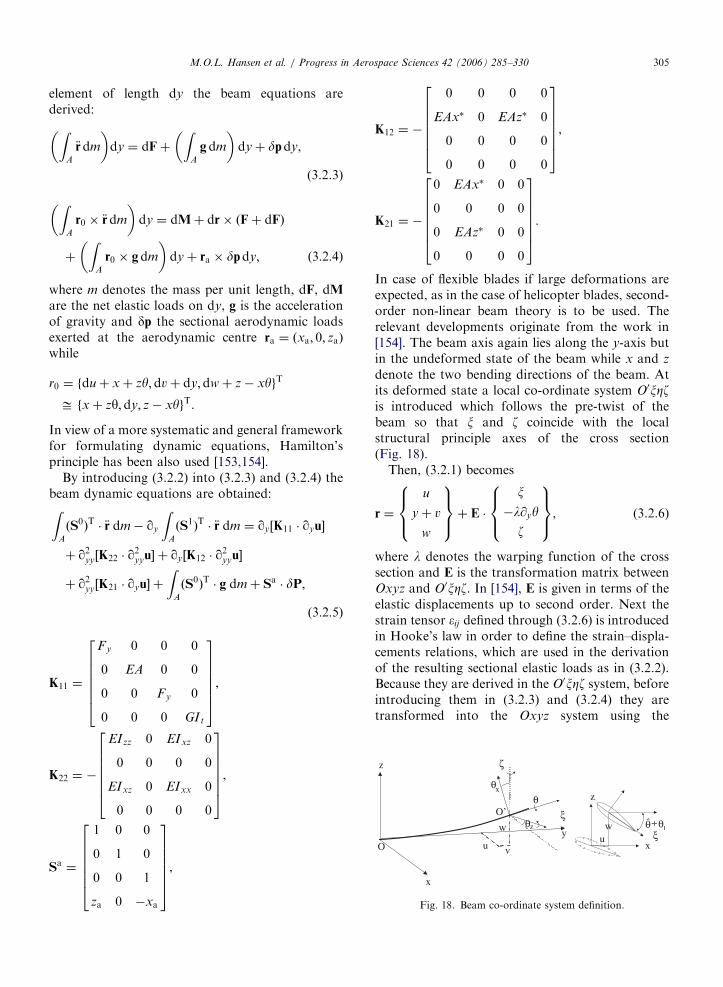
ARTICLE IN PRESS
x
z
yu
w
vO
Orsquoz
xz
xu
w θtθ
ζ
ξ
ξ
θθ
θ +ˆ
Fig 18 Beam co-ordinate system definition
MOL Hansen et al Progress in Aerospace Sciences 42 (2006) 285ndash330 305
element of length dy the beam equations arederivedZ
A
eurordm
dy frac14 dFthorn
ZA
g dm
dythorn dpdy
(323)
ZA
r0 eurordm
dy frac14 dMthorn dr ethFthorn dFTHORN
thorn
ZA
r0 gdm
dythorn ra dpdy eth324THORN
where m denotes the mass per unit length dF dMare the net elastic loads on dy g is the accelerationof gravity and dp the sectional aerodynamic loadsexerted at the aerodynamic centre ra frac14 ethxa 0 zaTHORNwhile
r0 frac14 fduthorn xthorn zy dvthorn dydwthorn z xygT
ffi fxthorn zy dy z xygT
In view of a more systematic and general frameworkfor formulating dynamic equations Hamiltonrsquosprinciple has been also used [153154]
By introducing (322) into (323) and (324) thebeam dynamic equations are obtainedZ
A
ethS0THORNT euror dm qy
ZA
ethS1THORNT euror dm frac14 qyfrac12K11 qyu
thorn q2yyfrac12K22 q2yyu thorn qyfrac12K12 q
2yyu
thorn q2yyfrac12K21 qyu thorn
ZA
ethS0THORNT g dmthorn Sa dP
eth325THORN
K11 frac14
Fy 0 0 0
0 EA 0 0
0 0 Fy 0
0 0 0 GIt
2666664
3777775
K22 frac14
EIzz 0 EIxz 0
0 0 0 0
EIxz 0 EIxx 0
0 0 0 0
2666664
3777775
Sa frac14
1 0 0
0 1 0
0 0 1
za 0 xa
2666664
3777775
K12 frac14
0 0 0 0
EAx 0 EAz 0
0 0 0 0
0 0 0 0
2666664
3777775
K21 frac14
0 EAx 0 0
0 0 0 0
0 EAz 0 0
0 0 0 0
2666664
3777775
In case of flexible blades if large deformations areexpected as in the case of helicopter blades second-order non-linear beam theory is to be used Therelevant developments originate from the work in[154] The beam axis again lies along the y-axis butin the undeformed state of the beam while x and z
denote the two bending directions of the beam Atits deformed state a local co-ordinate system O0xZzis introduced which follows the pre-twist of thebeam so that x and z coincide with the localstructural principle axes of the cross section(Fig 18)
Then (321) becomes
r frac14
u
ythorn v
w
8gtltgt
9gt=gtthorn E
x
lyy
z
8gtltgt
9gt=gt (326)
where l denotes the warping function of the crosssection and E is the transformation matrix betweenOxyz and O0xZz In [154] E is given in terms of theelastic displacements up to second order Next thestrain tensor ij defined through (326) is introducedin Hookersquos law in order to define the strainndashdispla-cements relations which are used in the derivationof the resulting sectional elastic loads as in (322)Because they are derived in the O0xZz system beforeintroducing them in (323) and (324) they aretransformed into the Oxyz system using the
ARTICLE IN PRESS
ρk
rGk
OG O
xG x
zG z
yG
y y
z
x
O
x
y
z
O
Fig 19 Multi-body representation of a wind turbine
MOL Hansen et al Progress in Aerospace Sciences 42 (2006) 285ndash330306
transformation matrix E The final expressions arequite lengthy and the reader is referred to [154] It isnoted that compared to the classical beam modelsecond-order theory will produce fully completestiffness matrices containing many non-linear termsThe above non-linear beam model is a specificexample amongst several models of varying com-plexity which have been gradually developed start-ing from the Timoshenko beam theory byeliminating the ad hoc simplifying assumptions ofthe original model [155ndash158]
Regarding wind turbines almost all structuralmodels are based on classical beam theory[150153159ndash162] This is partially due to the factthat wind turbine components are far more rigidcompared to helicopter blades for which non-lineartheory has been developed Furthermore most of thedifficulties in analysing wind turbine systems aregenerated by the aerodynamics and in particular theonset of stall which is certainly less pronounced onhelicopter rotors Current designs are quite stiff sothat non-linear beam modelling is not expected tochange drastically the quality of predictions besidesproviding a sound basis for including the geometricalnon-linearities [163] However if wind turbinesbecome more flexible it could become necessary toadopt such kind of structural modelling
Regardless the details the beam equations arefourth order with respect to bending and secondorder with respect to tension and torsion So for aFE approximation of the equations C1 shapefunctions are used for uw and C0 for v and y Atthe element level uw are approximated with third-order polynomials and the DOFs are the values andspace derivatives at the end nodes while v and y areapproximated with first-order polynomials and theDOFs again at the end nodes In some models andcertainly when the second-order beam theory isapplied second- and third-order polynomials areused respectively for v and y In this case the mid-point as well the points at 13 and 23 interior pointsare used as nodes So within an element lsquolsquoersquorsquo
ueethy tTHORN frac14 NeethyTHORN ueethtTHORN (327)
where NeethyTHORN is the matrix containing the shapefunctions and ueethtTHORN the vector of the DOFs at thenodes of the elements [164] As in Section 31concerning the principle of virtual work which inthe FEM terminology is the Galerkin formulationof the problem is used to generate the discreteequations With reference to (325) taken symboli-cally as Zethu _u eurouTHORN frac14 0 for any admissible virtual
displacement field du we require that
Z L
0
duT Zethu _u eurouTHORNdy
X
e
Z Le
0
duTe Zethue _ue euroueTHORNdy frac14 0 8du eth328THORN
Because dueethy tTHORN frac14 NeethyTHORN dueethtTHORN it follows that
Xe
Z Le
0
NeT ZethNeueNe _ueN
e euroueTHORNdy frac14 0 (329)
which is a set of second-order ordinary equations intime with respect to ueethtTHORN Although Z can containnon-linear terms it can always be written in theusual form
MethuTHORN eurouthorn Cethu
THORN _uthorn Kethu
THORN u frac14 Qethu
THORN (3210)
where the mass damping and stiffness matrices aswell as the generalized loads in the RHS in generalwill depend on the displacement field and its timeand space derivatives (noted by a tilde)
ARTICLE IN PRESS
y
O
q8 q9 q10 q11q12 q13
yG y
z
x
O
x
y
z
OG O
xG x
zG z
q1 q2 q3 q4q5 q6
q7
q14
Fig 20 A typical definition of the q DOF on a HAWT
MOL Hansen et al Progress in Aerospace Sciences 42 (2006) 285ndash330 307
The main components of a wind turbine are theblades the drive-train and the tower (Fig 19) Theyare all modelled as beam structures and typically thestructural properties are assumed for each compo-nent to continuously vary along the correspondingelastic axis However localized properties can beadded in the form of concentrated masses dampersor springs The gearbox (if present) the generatorthe hub are usually added in this way Otherexamples are the flexibility or damping character-istics of the yaw bearing or the pitch mechanismThe involvement of different body motions for eachcomponent in combination with the connectionswhere loads and displacements are communicatedfrom one component to the other calls for a globalformulation of the dynamic problem To this endmost works adopt a multi-body approach [165]which consists of considering each componentseparately subjected to appropriate boundary con-ditions which fit the different components into thecomplete configuration In such an approach theelastic DOF of each component are defined as localelastic displacements to which rigid body motionsare added through the kinematic boundary condi-tions see eg [161166167] for a more generaldiscussion It is also possible to introduce the globaldisplacements and rotations at each node instead ofthe local ones [153] allowing a unified description ofthe complete configuration In this case howeverthe non-linearities of the connections are introducedimplicitly and therefore linearization can only beperformed globally which is not always desirable
In multi-body modelling each component k isassigned a local coordinate system Oxyz with itsundeformed elastic axis along the y-axis Then theposition of a point with respect to the fixed systemrGk can be expressed with respect to its localposition rk (defined as in (321)) as follows
rGk frac14 qk thorn Ak rk (3211)
where qk denotes the position of the origin of thelocal system with respect to the fixed system and Ak
denotes the local to global transformation matrixThe exact form of qk and Ak depends on thekinematic conditions introduced when joining (con-necting) the various components (ie blades-to-hubor drive-train-to-tower) Depending on the type ofconnection common global displacements androtations are assigned for the restricted DOF whichare identified to either an existing elastic DOF (shaftbending at the hub) or a rigid body motion (bladepitch) The component contributing the kinematics
will in response receive from the rest of theconnected components their internal (or reaction)loads This operation involves co-ordinate systemtransformations between the components The setof kinematical DOF involved in the definition of qk
and Ak for all components is denoted collectively asq So qk frac14 qk(q t) and Ak frac14 Ak(q t) qk is defined asa mixed series of translations and rotations whereasAk is defined solely as a sequence of rotations Atypical example is shown in Fig 20 where q1ndashq6 arethe elastic DOF at the top of the tower q8ndashq13 arethe elastic DOF of the drive train at the hub and q7and q14 are the yaw angle and the pitch of the bladerespectively By introducing (3211) into (325) thecentrifugal and Coriolis terms of the inertia loadsappear as a result of the time derivatives of Ak whilein the Hamiltonrsquos principle approach they areproduced automatically
By combining the equations of all componentsthe complete system of the dynamic equations forthe wind turbine is obtained in the form of (3210)with respect to an extended vector of DOFuext frac14 u q
By construction qk and Ak will depend
on unknown DOF while at the same time theycorrelate the state of the components in contact sothe terms they generate are non-linear with respectto the unknown DOF uk and q Linearization in thiscase is a tedious procedure which must be donecarefully and systematically Fortunately softwareusing symbolic mathematics such as Mathematica
ARTICLE IN PRESSMOL Hansen et al Progress in Aerospace Sciences 42 (2006) 285ndash330308
are available which are strongly recommended Theprocedure is based on Taylorrsquos expansions of allvariables and retaining of first-order terms Alter-natively the extended version of (3210) can besolved directly through an iterative procedure ineach time step which can use the linearized solutionas a starting predictor
4 Problems and solutions in wind turbine
aeroelasticity
In the following section the use of aeroelasticcodes on wind turbine constructions includingstability studies will be illuminated mainly throughexamples
41 Aeroelastic stability
Wind turbines suffer from low structural damp-ing which can become critical under certain opera-tional conditions Most problems appear on theblades that receive almost 100 of the loading Inparticular the onset of stall plays a decisive role notonly on stall-regulated machines but also on pitch-regulated ones around rated conditions On theother hand the blades are made of compositematerials for which the knowledge on damping issubstantially inferior compared to steel or concreteconstructions The damping of composite structuresdepends on the ambient temperature So dependingon the season or the time during the day thestructural damping of the blades can decreasesubstantially Furthermore aging always degradesthe damping of composite structures There is adefinite need to increase structural damping andsignificant effort has been put recently on itsmodelling in composite structures as well as in theirappropriate design This is one direction of researchregarding the improvement of the stability char-acteristics of modern wind turbines see [168] for areview of the current developments Damping isrequired to suppress the onset of vibrationsgenerated by the unsteady aerodynamic loads thatinteract with the wind turbine structure First theaeroelastic modelling of wind turbines is consideredand then on this basis the aeroelastic stabilityproblem is formulated and the relevant availablemethods are reviewed
Aerodynamic modelling involves the calculationof the aerodynamic loads that also depend on thedynamics of the system The flap and lag vibrationsare interpreted by the incoming flow as a change in
the effective angle of attack indicating strongaeroelastic coupling All the currently availableaeroelastic tools for wind turbines use 2D dynamicairfoil data models such as the BeddoesndashLeishmannor the ONERA model They provide aerodynamiccoefficients as functions of the aerodynamic statevariables that satisfy appropriate dynamic equa-tions [17169] In either model the equations are 2Dand so they are applied on a strip-by-strip basismeaning that there is no interaction in the radialdirection This fits well with BEM modelling of theoverall aerodynamic analysis In fact the followingpresentation is referred to the BEM context sincemost existing stability models are based on it If apotential flow model is applied then the attachedpart of lift can be associated to potential lift whilethe rest is simply added [163] If the potential flowmodel is enhanced with a separation model thereshould be correlation on both aspects [58] How-ever the latter has not been applied yet inaeroelastic computations
By considering a blade section at a radial positionas shown in Fig 1 the local aerodynamic loadsacting on this section of the blade can be written asfollows since the lift is perpendicular and the dragparallel to the relative wind
py frac14 L sin fD cos f
pz frac14 L cos fthornD sin f
My frac14M eth411THORN
where L D are the lift and drag forces M is thepitching moment f is the local flow angle withrespect to the rotor plane Once the induced velocityhas been determined the local effective incidence aand relative flow velocity can be calculated as shownin Section 21 They will depend on the elasticdeformations and the velocities the rigid bodymotions and if appropriate orientation changes asin pitch and yaw variations In order to obtain aunified description of the coupled aeroelasticproblem a so-called aeroelastic finite element isdefined [170] which in addition to the elastic DOFthe aerodynamic state variables added For examplein the ONERA model there will be in total eightadditional DOF Because the dynamic equations forthe aerodynamic state variables only can be firstorder in time in order to produce a consistentcoupled system they can be differentiated as in[171] Therefore they can be assembled togetherwith the dynamic equations in the form of (3210)where the vector of the unknowns is further
ARTICLE IN PRESSMOL Hansen et al Progress in Aerospace Sciences 42 (2006) 285ndash330 309
extended to include the additional aerodynamicDOF Another approach used in [172] is tointroduce the modal expansion of the structuralDOF at stand still which better conditions thecoupled system
On the above basis it is possible to formulate theaeroelastic stability problem for wind turbinesWithin the context of linear theory stabilityboundaries are obtained by examining the evo-lution of small perturbations with respect to asteady state or a periodic solution acting asreference To this end the original equations arelinearized with respect to the reference state andthe resulting system solved with respect to thefluctuations
Methuref THORN eurouthorn Cethuref THORN _uthorn Kethuref THORN u frac14 Q (412)
where M C and K depend only on the referencesolution If the matrices do not depend on time(412) is reformulated into a first-order system
_y frac14 D ythorn b y frac14 u _un oT
(413)
The eigenvalue analysis of D provides the eigen-frequencies and damping of the system [173] This ispossible when the reference state corresponds to asteady solution as in the case of an isolated bladeHowever when analysing the complete windturbine configuration due to the rotation of theblades the reference state should correspond to aperiodic equilibrium state with reference to the rotorspeed which is assumed constant In this case thecorresponding theoretical framework is Floquetrsquostheory which for a large system is computationallyheavy [174] If the blades are identical and thenumber of blades NX3 which is the most frequentcase it is possible by means of multi-bladetransformation to eliminate the periodic coefficientsin the coefficients of (412) and therefore be ableto still use eigenvalue analysis [175] In this contextthe non-linear equations of the system are inte-grated in time until such a periodic state is attainedIn the case of an unstable situation because thetime domain response will contain significantcomponents in all of the basic eigenfrequencies ofthe system the reference state is obtained bytruncating the response so as to retain only its 1and Nrev components To this end all DOF in therotating system qm m frac14 1 NX3 are reformedqm frac14 q0 thorn qc cos cm thorn qs sin cm where cm frac14 Otthorn
eth2p=NTHORNethm 1THORN is the corresponding azimuth loca-tion Next the equations for the blade DOFs are
rearranged by applying the operators eth1=NTHORNPN
mfrac141
eth THORN eth2=NTHORNPN
mfrac141eth THORN cos cm and eth2=NTHORNPN
mfrac141eth THORN
sin cm This is performed after the periodic solutionhas been obtained over one period of rotation Theresulting equations will be in the non-rotating frameand contain only higher harmonics (3rev andhigher) By averaging over one period the finalconstant coefficient system is obtained in the formof (413) For the blades y will contain thecorresponding q0 qc and qs DOF and their timederivatives for both the purely structural and theaerodynamic DOF [171] In the above approach it isworth noticing that the averaging procedure willforce the reference state to appear in the equationsThis is an important aspect when dealing with non-linear systems
Stability of wind turbines has been consideredsystematically in Europe in the late 1990s [176] whiletoday there is an on-going activity under the EUfunded project STABCON Several linear stabilitytools have been produced along the lines describedabove and good correlation has been obtainedamongst the different codes see [177] and thereferences cited Inevitably linear theory is approx-imate so the results it produces are subject to crosschecking Clearly flutter measurements are difficultto obtain because of the involved risk therefore it isindispensable to rely on theoretical developmentswhich will be discussed in the next section
42 Aeroelastic coupling linear vs non-linear
formulations
Linearization of the aeroelastic equations cer-tainly offers computational efficiency However it isnot always appropriate For the structure lineartheory requires that the deformations and displace-ments are small an assumption not always validFor the aerodynamics and its coupling with thestructure linearization will suppress some depen-dencies involved in (411) and therefore influencethe estimation of the aerodynamic damping In thisconnection the use of semi-empirical unsteadyaerodynamic models introduces still unresolveduncertainties Furthermore there are cases in whichthe multi-blade transformation is not applicable egwhen blades are non-identical or when the rota-tional speed varies
Retaining fully the non-linearities of the aero-elastic problem has the following consequences thestructure is considered at its deformed state thecoupling conditions among the components are
ARTICLE IN PRESSMOL Hansen et al Progress in Aerospace Sciences 42 (2006) 285ndash330310
taken in their full form and the aerodynamicequations are not simplified The last point isimportant with respect to the best possible estima-tion of the aerodynamic damping within themargins offered by the semi-empirical models usedin the currently available aeroelastic tools In thisrespect multi-body analysis which has beenadopted in most of the existing stability tools[161178ndash181] offers this option by constructionprovided that the structural model considers theconstruction at its deformed state and the codetakes this into account in the definition of the localaerodynamics
Under such conditions the information of thestability characteristics of the wind turbine arecontained in the time signals of the loads calculatedthrough a non-linear time domain simulation Thereexist two types of methodologies for retrieving thisinformation the one is based on the work-basedapproach [176] while the other is using signal-processing techniques In the work-based methodany mode shape is excited and loads are recordeduntil a steady periodic state has been reached Thenthe aerodynamic damping is estimated by the workof the aerodynamic loads over the last period underthe assumption that there is no energy interchangebetween the modes through the aerodynamic loadsIn the signal processing approach the system isharmonically excited for a finite duration Then thetransient response following the abrupt terminationof the excitation is recorded wherefrom the aero-elastic damping and frequency of the specific modeare determined There are two different methodsboth well documented in the literature [182ndash184]that can be used the moving block method and themethod of Hilbert transform The moving blockmethod is a FFT based method commonly used inrotorcraft applications [182184] The transientresponse amplitude is computed on a block of datausing a FFT calculation The block is then movedforward by a single point in time and the computa-tion of the transient response amplitude is repeatedThe linear fit for the slope of the natural logarithmof the sequence of response amplitudes in time(peak plot) provides the damping (Fig 21) In theHilbert method the transient response y(t) and itsHilbert transform ~yethtTHORN are used to define theenvelope signal AethtTHORN frac14
ffiffiffiffiffiffiffiffiffiffiffiffiffiffiffiffiffiffiffiffiffiffiffiffiffiy2ethtTHORN thorn ~y2ethtTHORN
p[183184]
For a transient response typical of a viscouslydamped system a line can be fitted to the logarithmof this envelope The slope of this line as in the caseof the moving block method gives the damping
(Fig 22) Comparing the two it has been found thatthe Hilbert method has certain advantages over themoving block method In particular the Hilbertdamping analysis provides an estimate of thedecaying envelope signal so it can be used inassessing the non-linear damping characteristics ofa mode Therefore it is not limited by the assump-tion of the viscous damping as the moving blockmethod does Moreover experience has shown thatthe Hilbert method is more efficient in calculatingthe damping of spectrally close modes [163]
43 Examples of time simulations and instabilities
In this section the challenges in aeroelastic design ofwind turbine rotors will be addressed and in particularthe phenomenon of aeroelastic instability of windturbine rotors will be explored by showing examplesof simulation results on a wind turbine design
Back from the beginning of development ofmodern wind turbine rotors in the late seventiesthere has been concern about the problems thatcould arise due to aeroelastic instability In parti-cular the use of the stall regulation principle wasuncertain as it was foreseen that a flapwiseinstability (so-called stall flutter) would occur whenoperating in the stall region due to the negativeslope of the CL vs a curve However it turned outthat the flapwise instability during operation in stallwas not the most critical problem but instead theedgewise instability resulting in edgewise bladevibrations The first experimental evidence of thisinstability was seen in the mid nineties and initiatedconsiderable research activities in order to explorethe phenomenon and provide practical solutionsBelow is mainly focused on this instability as thisserves as a good example to illustrate the problem ofaeroelastic instability in more general terms
In the more recent wind turbine designs theregulation of the turbines has shifted from stallregulation to pitch control where the operationalrange for the flow over the blade moves to low angleof attack at high wind and thus away from the stallregion This has almost removed the instabilityassociated with stall during operation but it is stillso that the edgewise blade modes are aerodynami-cally low damped on the pitch regulated turbines
A major instability problem on the modernturbines is seen when the rotor is parked or idlingat very low RPMs at wind speeds above stop windspeed which typically is around 25ms Again it istypically edgewise dominated instability problems
ARTICLE IN PRESS
3540
4550
tim
e (s
ec)
-35
E+
06
-3E
+06
-25
E+
06
-2E
+06
-15
E+
06
-1E
+06
tower top tilt bending moment (Nm)
12
34
freq
uenc
y (H
z)
0
5E+
08
1E+
08
15E
+08
2E+
08
25E
+08
3E+
08
FFT of the tower top tilt bending moment (Nm)
Δt
data
19
190
5
191
191
5
192
192
5
193
193
5
194
00
51
15
22
53
t (se
c)
-ζ Ω
n
log of response amplitude
Fig21Schem
aticdescriptionofthemovingblock
dampinganalysis
MOL Hansen et al Progress in Aerospace Sciences 42 (2006) 285ndash330 311
ARTICLE IN PRESS
-15e+06
-1e+06
-500000
0
500000
1e+06
15e+06
2 4 6 8 10 12 14
tow
er to
p til
t ben
ding
mom
ent (
KN
m)
time (s)
transient signalenvelope signal
envelope signal exp fit
Fig 22 Envelope signal calculation of the tower top tilting moment transient response using the Hilbert transform method for the same
signal as in Fig 21
1000
800
600
400
200
0
-2000 50 100 150 200 250 300
Time [sec] Time [sec]
ED
GE
WIS
E B
LA
DE
RO
OT
MO
ME
NT
[U
NC
AL
IBR
AT
ED
]
ED
GE
WIS
E B
LA
DE
RO
OT
MO
ME
NT
[U
NC
AL
IBR
AT
ED
]
EDGEWISE BLADE VIBRATION INSTABILITY EDGEWISE BLADE VIBRATION INSTABILITY--MEASUREMENT
1000900800700600500400300200100
0-100
200 210 220 230 240 250 260
Fig 23 Measured edgewise blade root moment on a stall regulated rotor at high wind Detail of the time track to the right
MOL Hansen et al Progress in Aerospace Sciences 42 (2006) 285ndash330312
related to stall of the blade A simulation examplewill be shown later to illustrate this problem
Finally the flutter instability will be addressed Itseems that the increased up scaling of the turbineshas led to rotor and blade designs where the flutterspeed is not so far away from normal operationalspeed Also this instability will shortly be illustrated
431 Edgewise blade vibration instability
As mentioned above the first experimentalevidence of this instability was seen in the mid
nineties on stall-regulated rotors with a diameter of35ndash40m An example is presented in Fig 23 and it isseen that the amplitude of the edgewise blade rootmoment (which at steady conditions vary sinusoidalwith 1p due to the gravity) increases 2ndash3 times dueto instability during operation in stall The experi-mental evidence of the edgewise instability led toconsiderable research on this subject and a majorEuropean project lsquolsquoPrediction of Dynamic Loadsand Induced Vibrations in Stallrsquorsquo funded by the EUwas carried out in the period from 1995ndash1998 [176]
ARTICLE IN PRESSMOL Hansen et al Progress in Aerospace Sciences 42 (2006) 285ndash330 313
The origin of the instability is simple If a rotatingairfoil section is harmonically translated along anaxis xB and the direction of this axis yRB relative tothe orientation xR of the rotor plane is varied theaerodynamic damping coefficient for the sectionvaries considerably see Fig 24 from [185] For lowyRB which means in-plane or edgewise vibrationdirection the damping coefficient is negative even atlow wind speed For vibrational directions close to901 which corresponds to out-of-plane or flapwisedirection the damping coefficient is strongly depen-dent on the inflow wind speed It is highly damped
Fig 24 The aerodynamic damping coefficient c_xx_b for a rotating a
different inflow velocities from [185]
Fig 25 Damping characteristics computed for a rotating isolated bl
at low wind but close to zero or negative damped athigh wind
On a complete rotating blade the direction ofvibration depends on the structural design of theblade as well as of the complete turbine structureThe movement of the tip section of the blade willnow no longer necessarily be along a straight lineHowever typically the tip section of the blade in thefirst flapwise mode will be on a path almostperpendicular to the rotor plane and in the 1stedgewise mode it will almost be in-plane It is thusexpected that the basic damping characteristics of
irfoil section as function of vibration direction yRB and at three
ade using the linear aeroelastic stability tool HAWCStab [186]
ARTICLE IN PRESSMOL Hansen et al Progress in Aerospace Sciences 42 (2006) 285ndash330314
the whole blade will be comparable with thecharacteristics of a single airfoil section Using thelinear stability tool HAWCStab the dampingcharacteristics for a rotating blade can easily bederived and the computed damping characteristicsfor a rotating 19m blade (500 kW rotor) corre-sponding to the blades of the rotor where theexperimental instability was shown in Fig 23 areshown in Fig 25 from [186] It is seen that thedamping for the first flapwise mode varies fromhighly positive values at low wind speed and tovalues close to zero at 14ms and then increasingslightly at higher wind speeds It should be notedthat the influence of using unsteady blade sectionaerodynamics is shown (modelled with the BeddoesLeishman model in the present case) and that thishas considerable influence on the aeroelastic damp-ing Generally the unsteady aerodynamic effectsincrease the damping The damping for the firstedgewise mode is seen to decrease gradually withincreasing wind from being slightly positive at lowwind to slightly negative at high wind Finally itshould also be noted that the damping shown is thetotal damping including the structural dampingwhich in the present case is around 2 for the firstflapwise mode and 3 for the first edgewise mode
The final step in model complexity is nowobtained by going to a full aeroelastic model ofthe turbine comprising the dynamics of the shaftthe nacelle and the tower The aeroelastic stability
Fig 26 Aeroelastic damping computed with the aeroelastic stability HA
speed
results using HAWCStab is for the complete windturbine see eg Fig 26 from [186] showing theaeroelastic damping for the first 10 mode shapes(numbered from lowest frequency) It is seen thattwo mode shapes are negatively damped at highwind speed and that one mode shape is close to zeroand slightly negatively damped at the highest windspeed For comparison time simulations with theaeroelastic code HAWC [187188] is performed onexactly the same turbine model at a wind speed of 8and 16ms respectively in order to see if theinstability at high wind speed predicted by the linearstability tool can be confirmed by the HAWCmodel with non-linear aerodynamics The com-puted edgewise blade root moment shown in Fig 27confirm the instability at high wind and comparesvery well with the measured instability shown inFig 23 It is thus demonstrated that the edgewiseinstability problem can be predicted in both timesimulations and using linearized stability analysisHowever as will be demonstrated below theedgewise vibration instability is much more complexthan just edgewise vibrations of the individualblades but comprises the dynamic characteristicsof the whole turbine This understanding is vital forthe development of design solutions preventing theinstabilities
In order to analyse the instability in more detailsthe use of parallel aeroelastic time simulations on aturbine with a stiff structure is made In this case the
WCStab [186] Three modes have negative damping at high wind
ARTICLE IN PRESSMOL Hansen et al Progress in Aerospace Sciences 42 (2006) 285ndash330 315
loads on the different components will mainlyreflect the direct load input from the externalaerodynamic forces and from gravity forces Itshould be mentioned that the simulations areperformed at two average wind speeds of 8 and16ms respectively and with a turbulence intensityof 12
A power spectral density analysis of the simulatededgewise blade root moment shows a distinct peakat 307Hz which is close to the frequency of the firstedgewise mode for a single rotating blade which is319Hz see Fig 28 The response at 16ms of theflexible turbine at this frequency is seen to be severalorders of magnitude bigger than the response of thestiff turbine indicating an instability situationSomewhat the same tendency is seen at 8ms but
Fig 28 Comparison of power spectra of edgewise blade root momen
Fig 27 Time simulation with the aeroelastic code HAWC on a 50
with considerable less difference between the re-sponse of the stiff and flexible turbine indicating lowdamping but not an instability
Analysing further the results of the stabilityanalysis with HAWCStab as shown in Fig 26 itcan be derived from the results of the model that thethree mode shapes that are negatively damped orvery low damped at 16ms are
t fo
0 k
mode no 1 with frequency 077Hz and damping605
mode no 3 with frequency 093Hz and damping433
mode no 7 with frequency 273Hz and damping
159
r a flexible and a stiff turbine respectively at 8 and 16ms
W stall regulated rotor at two wind speeds 8 and 16ms
ARTICLE IN PRESSMOL Hansen et al Progress in Aerospace Sciences 42 (2006) 285ndash330316
The numbering in HAWCStab of the modes iswith increasing mode number with increasingfrequency starting with the lowest frequency Modeno 1 and no 3 are both modes where lateral towerbending is the main motion together with edgewisebending of the three blades and torsion of the mainaxis The edgewise movement of the blades are all inphase and the difference between the two modes isthe direction of the edgewise bending relative to thetower bending Comparing again the results of thelinear stability analysis with the time simulationresults the instability of the lateral tower bendingdominated modes is confirmed by the spectra of thetower top and tower bottom lateral bendingmoments Figs 29 and 30 A distinct peak at
Fig 29 Comparison of power spectra of tower top lateral moment
Fig 30 Comparison of power spectra of tower bottom lateral mome
079Hz is seen in both tower top and tower bottomspectra at 16ms and this peak cover probably alsoa considerable content at the 093Hz which was thefrequency of mode no 3
It can be noticed that the HAWCStab results donot contain an unstable mode with a frequencyaround 307Hz (the edgewise instability) as seen inthe time simulation results However mode no 7 isin fact the response on the non-rotating turbinestructure from the edgewise vibrations at 307HzThe edgewise vibrations in the present case is a so-called backward whirling edgewise mode wherethere is a phase shift of 1201 between the movementof the blades This whirling mode results in shaftand tower bending but with a frequency shifted 1p
for a flexible and a stiff turbine respectively at 8 and 16ms
nt for a flexible and a stiff turbine respectively at 8 and 16ms
ARTICLE IN PRESSMOL Hansen et al Progress in Aerospace Sciences 42 (2006) 285ndash330 317
(p is the rotational frequency) up and downrespectively compared with the frequency in therotating system As 1p in the present case is 045Hza peak in the spectra of tower bending at afrequency of around 307ndash045Hz equal to 262Hzis expected which is also seen in Figs 28 and 29However in the HAWCStab results a slightlyhigher frequency 273Hz was seen for this mode
The presented example of the edgewise bladevibration instability has shown that the low aero-dynamic damping of an airfoil section undergoing amotion along a path close to the chordwise directioncan cause instability of quite different modes on theturbine at the same time The design challenges withthe objective to minimize the influence of lowaerodynamic damping or instability are thus big aseg changes in tower design could lead to egedgewise vibrations on the rotor A number ofdifferent methods to reduce the risk for edgewisevibrations on stall-regulated turbines have beeninvestigated [176186] and comprises eg changes ofthe stalling characteristics of the airfoils by so-calledlsquolsquostall stripsrsquorsquo as well as structural design of theblades to achieve optimal vibrational directions
432 Instability problems of parked rotors
The turbines are normally designed to operate upto a certain maximum wind speed and above thiswind speed the turbines are shut down In thestopped conditions the rotors can be completelyparked or they can idle with low rotational speeddepending on the actual design of the controlsystem As part of the certification of the turbineit must be shown that the turbine can withstand the
Fig 31 Simulation of a parked rotor at 50ms and a yaw error of 601
power spectrum of the same signal to the right
wind loads at extreme wind speed conditions withparked rotor and the wind coming from anydirection in the case that the yawing system of theturbine is not functioning
As an example the simulation of a rotor parkedat a wind speed of 50ms and a yaw error of 601 isshown in Fig 31 The turbine is the same as aboveand the time track of the edgewise blade rootmoment indicates low damping as the amplitudesvary much in time To the right in Fig 31 is shown apower spectrum of the same signal and it shows thatthe blade mainly vibrates in two modes mode 3 at afrequency of 093Hz which was described aboveand the first edgewise blade frequency at about319Hz For the present inflow direction thevibrations are not unstable but it has to bedocumented for all inflow directions
433 Flutter instability
The last example of an instability is flutter This isa well-known instability from the aircraft industrybut has not yet been a problem on wind turbinesand has probably not been seen on commercialturbines However with the increasing size of theblades it seems that the flutter speed decreases dueto increasing structural flexibility of the blades andnot least the torsional frequency decreases There-fore it is a good idea to include a flutter speedcalculation in the design verification for eg 50mblades and above
Flutter involves two DOF of the blade torsionand translation The flutter speed decreases whenthe frequency of these two DOF approach eachother For 50m blades the frequency of the first
Time track of the edgewise blade root moment to the left and a
ARTICLE IN PRESSMOL Hansen et al Progress in Aerospace Sciences 42 (2006) 285ndash330318
flapwise mode is typically slightly below 1Hz andthe frequency of the first torsional mode willtypically be in the range from 5 to 8Hz Howeverit has been seen that the flutter instability can occurby a coupling of the second flapwise mode and thefirst torsional mode of the blade and of course this isalso a reason for a decreasing flutter speed on thebigger blades Another important design parameterfor the flutter instability is the centre of mass in theblade sections relative to the centre of the elasticaxis As the centre of mass moves away from theelastic axis in the direction of the trailing edge theflutter speed decreases
An example of a simulated flutter instability isshown in Fig 32 The blade does not represent anindustrial blade but has selected structural para-meters which give a rather low flutter speed Thesecond flapwise mode for the blade is slightly above2Hz and the first torsional frequency is around6Hz Further the centre of mass is positioned 10of the chord length behind the elastic axis Theexample is mainly intended to show the character-istics of the flutter instability which is completelydifferent from the instabilities that have been seenso far In the simulation the rotor is free to speed upas the generator is disconnected When the flutterspeed is reached the instability develops within 1ndash2 sand this is completely different from eg theedgewise blade instability that can build up over aminute or more This characteristic means the bladeprobably will be damaged immediately if the flutterspeed is reached A further consequence of this fastdevelopment is that the flutter can occur at a lowerrotational speed of the rotor if there is a yaw errorThis is demonstrated in the right part of Fig 31
Fig 32 Example of flutter instability on a 50m test blade where the r
right there is a yaw error of 501
where there is a yaw error of 501 Here therotational speed at flutter instability is 13 lowerthan if there is no yaw error and the wind speed isjust 8ms If the for example the yaw error of 501occurred at around the stop wind speed of 25msthe rotational speed at the flutter instability woulddecrease even further
5 Present and future developments of aeroelastic
models
The improvement of existing aeroelastic codesand the development of new aeroelastic models arehighly influenced by the design trends of new windturbines and trends in the siting of the turbinesbecause this determines the needs for new capabil-ities of the models
51 Areas with influence on the development of
aeroelastic models
511 Influence of up-scaling
So far the most important design trend has beenthe up-scaling which within the last 10 years hasincreased the maximum size of the mass producedturbines with a factor of 10 from about 500 kW witha rotor diameter of about 40m to 5MW turbineswith a rotor diameter of 120m The newest turbinesare all pitch controlled with variable speed andtypically with some type of cyclic pitch for loadalleviation An accurate modelling of these newflexible turbines has increased the requirements tosimulate complex coupled modes where the inte-grated flexibility of the tower of the drive train andof the blades and in interaction with the control is
otor is free to speed up To the left normal inflow whereas to the
ARTICLE IN PRESSMOL Hansen et al Progress in Aerospace Sciences 42 (2006) 285ndash330 319
important Also non-linear effects from consider-able deflections of the blades and the tower arebecoming important and the aeroelastic stabilitymust be predicted with a good accuracy Sometypical frequencies for a 5MW turbine could be
First tower bending frequency
02ndash025Hz
First flapwise frequency
08ndash10Hz
First edgewise frequency
09ndash11Hz
First blade torsional frequency
50ndash70Hz
The decrease in the fundamental turbine frequen-cies arising from the up-scaling has the effect thatexcitation from the turbulent inflow has increased asthe power spectrum of the turbulence peaks ataround 005Hz
512 Siting of the turbines
The major part of all new turbines is placed insmall or bigger groups and in some cases in windfarms with more than 100 turbines This means thatwake operation is part of the inflow conditionswhich has to be simulated in the derivation of thetotal design loads of the turbines Load alleviationby cyclic or individual pitch controls is importantfor such inflow conditions and the aeroelasticmodels should be suited for this
Still the major part of turbines are set up on landbut the offshore part will increase at least if a 5ndash10years interval is considered On land the best siteshave been used in many countries and thereforemore and more complex sites will be used Thismeans that rather complex inflow situations must bemodelled as for example complex shear and non-uniform turbulence over the rotor disc
513 Future trends in turbine design and siting
It seems that the speed of up-scaling might beslowed down for some years as the industry wantsto be more focused on turbine reliability One wayto improve this is to have the individual turbinemodels on the market for more years than seen inthe past
However the increasing offshore developmentwill support the up-scaling tendency as the tran-sport and erection of big turbine components is nolonger a major problem Further the higherfoundation costs offshore will also support the up-scaling trend
Extending the possible offshore sites to deeperwater new foundation types typical with multipleframes will be developed and the aeroelastic codes
should be able to handle these structures A furtherstep in the offshore development is the floatingturbines either as single floating turbines or moreturbines on the same floating frame
Finally the offshore market could have the effectthat the two bladed turbine with a teetered down-wind rotor again will be considered as an alternativeto the three-bladed machines The main barrier forthe development of two bladed turbines has beenthe low frequency noise from the blade passage ofthe tower shadow This will be of less importanceoffshore as the noise restrictions are much lowerhere
52 Areas of development in present and new codes
Influenced by the continuously increasing require-ments to the capabilities of the aeroelastic models asdescribed above existing models are being furtherdeveloped and improved and new codes are writtenBelow some important areas of development will bediscussed
non-linear structural dynamics
calculation of induction and its dynamics
wake operation
derivation of airfoil data for aeroelastic simula-
tions
complex inflow
aerodynamics of parked rotors and
off shore turbines including floating turbines
521 Non-linear structural dynamics
So far almost all aeroelastic codes have containedthe model assumptions of small deformations androtations but the increased flexibility of the turbineshave made uncertainty about the validity of thisassumption for the new designs The influence ofnon-linear effects on the dynamic response of aturbine was treated in a recent paper [189] anddifferent effects were considered For examplecharacteristics (frequency and damping) of the firstedgewise mode will typically change as function ofincreased flapwise deflection because the edgewisebending will couple more and more with thetorsional mode of the blade Besides increasedinfluence to non-linear effects from the flexibilityof the turbine components the new foundationsused offshore and in particular floating foundationscan contribute significantly to big deflections andrelated non-linear effects
ARTICLE IN PRESSMOL Hansen et al Progress in Aerospace Sciences 42 (2006) 285ndash330320
To overcome this uncertainty about the impor-tance of non-linear effects a few new non-linearaeroelastic codes have now been developed Siemenswind power has developed a non-linear codeBHawC based on co-rotaing elements [190] whilethe new non-linear code HAWC2 [191] developedby Risoe is based on multibody dynamics
The trend of including non-linear effects willcontinue in the future and codes based on modalexpansion techniques will be developed to includemore modes as eg the blade torsional mode
522 Calculation of induction and its dynamics
The unsteady aerodynamic air loads are directlydependent on the computed induction at the samepoint on the blade through the angle of attackTherefore an accurate prediction of induction is ofcrucial importance
As the rotor disc has become bigger and biggerrelative to the scales in the turbulent inflowincreasing variation in inflow conditions over therotor disc are seen Wind shear contributes to thisvariation in inflow The inflow variations results inlikewise considerable variation in the loadingexpressed through the local thrust coefficient CTlocal
over the rotor disc and thus also in induction Theinduction is therefore even in normal operationhighly dynamic and the induction model should beadapted to these conditions As an example Fig 33
Fig 33 Example of dynamic loading at a point close to the tip of a b
(reproduced from [192]) shows the variation of thelocal thrust coefficient at the outer part of the bladeon an 80m diameter turbine in normal operation
Another source contributing to the load varia-tions and thus to the dynamic induction is theeigenmotion of the blades This part is alsoincreasing due to up-scaling and due to the moreflexible designs As an example a blade with aflapwise frequency of 1Hz as mentioned above andvibrating with an amplitude of 1m will experience arelative velocity component perpendicular to thechord of around 76ms in maximum This valuecan directly be compared with the variations ininflow and is thus considerable Different develop-ments to improve the computation of inductionhave been seen One type of modelling is thecoupling of a numerical actuator disc model to thestructural part of the aeroelastic model So far suchmodels have mainly been used to verify the accuracyof BEM modelling As an example the aeroelasticcode HAWC at Risoe with a BEM-type inductionmodelling in the standard version has been devel-oped in another version HAWC-3D where theinduction is computed with a 3D actuator discmodel and used eg to investigate the accuracy ofyaw modelling [142193] see Fig 34 from [142] Inthe coming years aeroelastic codes coupled to anactuator disc or actuator line model for computa-tion of induction will certainly be further developed
lade on an 80m diameter turbine in turbulent wind from [192]
ARTICLE IN PRESS
Fig 34 Influence of yaw on the local inflow angle The curves show the difference in local inflow angle at yawed operation at 451
compared with non-yawed operation The HAWC model has a BEM induction model HAWC-3D a 3D actuator disc model and
EllipSys3D is a full 3D NavierndashStokes simulation from [142]
MOL Hansen et al Progress in Aerospace Sciences 42 (2006) 285ndash330 321
but probably mainly used for research and forverification of simpler codes and not so much in theaeroelastic codes used by the industry due to themuch longer simulation time
However besides a direct coupling of an actuatordisc or line method to an aeroelastic code in order tocompute the induction at each time step there areother ways to utilize the capabilities of an actuatordisc model One example is to compute theinduction characteristics of a rotor within its windspeed operational interval with an actuator disc andthen afterwards use these quasi-steady inductioncharacteristics in aeroelastic simulations for therotor The BEM method in the new HAWC2aeroelastic code developed at Risoe has beenimplemented in such a way that this method canbe used The method is shortly first to compute thelocal induction as function of local loading for theactual rotor in a number of calculation points ethn mTHORN over the rotor with an actuator disc
aethrn ymTHORN frac14 f CT rn ymeth THORNeth THORN
Afterwards these induction functions are then usedin the BEM method during time simulations on therotor instead of the unique single relationship from1D momentum theory CT frac14 4aeth1 aTHORN
In fact one of the main deficiencies of the BEMmethod is that this induction formula concerns thewhole rotor disc Deviations are seen in regions withconsiderable radial variation in the loading whichmeans in the tip or root region Another examplewhere the momentum induction formula does nothold is if the rotor disc is not plane eg conedrotors or rotors where the blades bend considerably
523 Wake operation
Most turbines are now set up in clusters or windfarms and this means that such turbines in part oftheir lifetime operate in wake from one or moreturbines In the international standard for design ofturbines IEC 61400-1 [2] the increased loading fromoperation in wake can be taken into account byusing an increased effective turbulence whichdepends on a number of parameters in theconsidered wind farm such as eg wind turbinespacing However it has turned out that in caseswhere more detailed knowledge of the increasedloading on the different turbine components fromwake operation is needed another more detailedaeroelastic modelling is needed than just increasingthe turbulence One such aeroelastic modelling hasbeen developed over the past few years [194195]The main components in the modelling is (1)
ARTICLE IN PRESSMOL Hansen et al Progress in Aerospace Sciences 42 (2006) 285ndash330322
computation of the wake deficit from the up-streamturbine with an actuator disc model (2) meanderingof this deficit from the big scales in the turbulenceand (3) additional turbulence within the wake Oneof the advantages of this new modelling comparedto the method using an effective turbulence is thatboth the mean yaw loads as well as the yawdynamics compare well with measurement Fig 35from [194] shows the loads as function of winddirection and full wake operation at a direction ofaround 2101 The highest mean yaw loads occur inhalf wake operation at around 1951 and 2201Recently the wake resulting from the interaction ofseveral turbines in a row was computed in [196] bycombining large eddy simulation of the NS equa-tions with the actuator line methodology
Fig 35 Measured and simulated loads at 8ms (crosses and full lines)
wake operation (full wake at around 2101 on x-axis) using a new aeroel
meandering from [194]
It is expected that the more detailed aeroelasticmodelling of wake operation will be developedconsiderably in the coming years because suchmodelling is necessary for the development ofadvanced control algorithms adapted for loadreduction in wakes The development of the newdetailed models can be in the direction like themodel described above but also using actuator linemodels or full 3D rotor models to compute the wakecharacteristics which can be fed into an aeroelasticsimulation
524 Derivation of airfoil data for aeroelastic
simulations
The airfoil data used in aerodynamic and aero-elastic simulations are of crucial importance for the
and at 10ms (squares and dashed lines) on a 80m rotor during
astic wake simulation method taking into account the wake deficit
ARTICLE IN PRESSMOL Hansen et al Progress in Aerospace Sciences 42 (2006) 285ndash330 323
accuracy of such simulations This was clearly seenin the result of the NREL blind test [137] where thedifference in the airfoil data used in the individualsimulation models probably were the most signifi-cant factor for the big variation between the outputof the different simulations However it should benoted that this result is not a representativeindicator of the uncertainty in the industry onaerodynamic and aeroelastic results on new turbinesas considerable experience has been learned fromolder rotor designs in order to adapt airfoil data setsso that computed rotor power and loads comparewell with measurements The drawback is that thisintroduces conservatism in the design and forexample can hinder the use of new airfoils There-fore methods and models to derive or correct airfoildata to be used in aeroelastic simulations have beena key issue for many years in the wind energyresearch community and will also be it in the nearfuture 2D wind tunnel airfoil data has so far beenthe common starting point to set up an airfoil dataset for simulations In order to correct for so-called3D flow effects and rotational effects some kind ofcorrection is typically applied [19ndash21197] Thecorrections reflect the increased lift and drag thatwas measured on different rotors in field rotormeasurements performed 10ndash15 years ago [198199]Full 3D CFD rotor computations later confirmedclearly the tendencies of the 3D flow effects androtational effetcts in the form of increased lift in theblade root region but also increased drag [137ndash139]
With the possibility of running full 3D simula-tions on a rotor a new source for derivation of 3Dairfoil data sets for input in aerodynamic and
2
18
16
14
12C1
1
08
06
040 5 10 15 20 25 30
r=14r=28r=42r=56r=69r=89r=94r=97
35 40α
Fig 36 Extracted 3D airfoil data in the form of CL CD data as functi
rotor computation Figure from [202]
aeroelastic codes has emerged Methods to extractthe airfoil data from 3D rotor computations havebeen developed [200201] One example of such aderived airfoil data set is shown in Fig 36 from[202] where a considerable increased maximum lifton the inboard stations are seen Within the nextfew years it is expected that a considerable effortwill be on further development of the methods toextract airfoil data from 2D wind tunnel data aswell as 3D CFD rotor data So far the CFDcomputations have mainly been used to extractquasi-steady data but they will in the future also beused to tune the parameters in the dynamic stallmodels
525 Complex inflow
Wind turbines are often set up in so-calledcomplex terrain which means some kind ofmountainous terrain because the wind potential isgood at such places However the consequence isthat the inflow conditions can vary considerablyfrom turbine to turbine due to local variations ofthe terrain As a result extreme wind shear has beenseen to occur over the rotor disc of turbines placedin such terrain and likewise the turbulence intensitycan be extremely high
The fast development of CFD codes has nowmade it possible to simulate the flow in detailsover the terrain spanned by a wind farm in suchcomplex terrain The flow data in the form of windshear and turbulence can be used as input inaeroelastic simulations There is thus a basis for asimulation tool to micro site turbines not only withrespect to energy production but also loads is
Cd
r=14r=28r=42r=56r=69r=89r=94r=97
α
05
045
04
035
03
025
02
015
01
005
00
5 10 15 20 25 30 35 40
on of angle of attack at different radial stations from a 3D CFD
ARTICLE IN PRESSMOL Hansen et al Progress in Aerospace Sciences 42 (2006) 285ndash330324
expected Thus type of modelling is certainly ofhigh interest for the wind turbine industrybecause considerable costs to repair turbines dueto extreme inflow conditions have been experiencedin the past
526 Aerodynamics of parked rotors
It is a common procedure to shut the turbinesdown at high wind typically at wind speeds in therange from 20 to 25ms Ultimate loads on parts ofthe wind turbine can occur during standstill condi-tions at very high wind speed whereas ultimate loadson other components will occur during operationbelow the stop wind speed
The aerolelastic codes are therefore also used tocompute the turbine response during standstillconditions and it is particularly the computationof the aerodynamic loads on the blades that isuncertain This is due to the requirement that theloads on the parked rotor shall be investigated withthe wind from all directions The models musttherefore be able to compute aerodynamic loads forangle of attacks in the complete range from ndash180o to180o Furthermore the inflow is turbulent so that itis highly unsteady aerodynamic loads and a severecomplication is that some inflow conditions oftenlead to instability with the blade vibrating in a modewith negative aerodynamic damping In a recent EUfunded project lsquolsquoKNOWBLADErsquorsquo different CFDcodes were used to explore some basic character-istics of the blade standstill aerodynamics [115]Because of the complexity of the aerodynamics it isalso believed that the use of CFD will be the mainpath to explore the standstill aerodynamics in thecoming years
Fig 37 Different support struc
527 Offshore turbines including floating turbines
Presently there are considerable research anddevelopment efforts on adapting aeroelastic modelsto simulate offshore wind turbines mounted on asub-structure standing on the sea-bed see Fig 37from [203] or on a floating foundation
Different approaches are seen in this develop-ment One line is characterized by a completeintegration of the standard aeroelastic model ofthe turbine with a hydroelastic model of the sub-merged supporting structure including the hydro-dynamic loads the wave loading and the soil forceson the part of the support structure in the sea bed[190191] In both these models the completestructure is described with finite elements and withengineering sub-models for computation of thehydrodynamic loads
Another line of modelling is to couple alsquolsquostandardrsquorsquo aeroelastic model to a separate modulesimulating the supporting structure including waveloads and hydro loads This approach has beenpresented by Repower [204] where the Flex5aeroelatic code is coupled with a standard packageASAS for computations of wave loads on off shorestructures In the third development line the mainidea is also to use a lsquolsquostandardrsquorsquo aeroelastic code andthen couple it to a super element of the foundationThis approach has been presented by Vestas [203]where the foundation is modelled with a finiteelement model but then decomposed to a superelement using the CraigndashBampton sub-structuringscheme Considerable efforts on further develop-ments of the aeroelastic models for off shoreapplications will be seen within the next years andwith more emphasis on deeper water installations
ture concepts from [203]
ARTICLE IN PRESSMOL Hansen et al Progress in Aerospace Sciences 42 (2006) 285ndash330 325
6 Discussion
On a wind turbine there is a strong couplingbetween the aerodynamic loads and the time-dependent structural behaviour of the constructionStatically a blade might change its twist and thus theangle of attack when deflected But also the anglesof attack are changed when the blades have avelocity relative to the fixed ground For instance ifthe tower is moving upstream and everything else isstiff it will be felt by the blades as an increased windspeed and thus higher angles of attack will bepresent along the blades The aerodynamic responsewill depend on how the lift and drag vary with theangle of attack In stall the lift will decrease yieldinga possible instability whereas for attached flow thelift will increase and thus creating a higher load seenby the blade opposite the movement indicatingstability On a real wind turbine not only the toweris vibrating but all other components as well whichdirectly feeds back to the angle of attacks and thusthe loads that again alter the motion To simulatethe aeroelastic response of a wind turbine a non-steady structural model including the inertia mustbe made Two methods ie the method of virtualwork applied on modal shape functions and theFEM are addressed To evaluate the aerodynamicloads the BEM is still the most widely used due toits simplicity and computing efficiency To obtainrealistic results some engineering adds-on arenecessary such as the Dynamic Wake DynamicStall and a yaw model which are thereforethoroughly described in this paper A BEM methodrelies however on airfoil data and the results aretherefore no better than the input To avoid theuncertainties of the engineering adds-on the Actua-tor Line model can be used since this methodresolves the physics of these models through the NSequations However the actual blades are notresolved and to estimate the aerodynamic lift anddrag airfoil data are still needed To avoid airfoildata one needs to solve the NS equations andresolve the blades and the possible boundary layersThis is extremely computationally costly and there-fore this model is not likely to replace the BEMmethod in the near future However the methodcan be used to extract airfoil data that can be usedin the less advanced models It is expected that theActuator Line model very soon will replace theBEM method since it contains less empirics Withthe AL model the wake is also a part of the solutionand therefore the effect from this wake on a wind
turbine placed further downstream can be calcu-lated These simulations are becoming very impor-tant as wind turbines are grouped in large (offshore)wind parks The inviscid flow models are included inthis paper mainly for historical reasons since theyhave played an important role in determining basicphysical features This type of model was eg usedto calibrate the time constants in the DynamicWake model Also a few Potential flow models existthat model the induced velocities and the wakebehind a wind turbine by shedding vortex blobsfrom the blade surface This model is similar to theAL model and may also in some aeroelastic codesreplace the BEM method
References
[1] Last og sikkerhed for vindmollekonstruktioner DANSK
STANDARD DS 472 [in Danish]
[2] IEC 61400-1 Ed3 CD 2 revision Wind turbines Part 1
design requirements Edited by IEC TC88-MT1 25ndash26
May 2004
[3] Hansen KS Performance Measurements on two Danish
630 kW WECS In Proceedings of the WIND POWERrsquo85
SERICP-217-2902 1985 p 130ndash5
[4] Hansen KS et al An evaluation of measured and predicted
fatigue loads for the Tjaeligreborg wind turbine In Proceed-
ings of ECWECrsquo93 Travemunde Germany 1993
p 579ndash82
[5] Ahlstrom A Aeroelastic simulation of wind turbine
dynamics Doctoral thesis in Structural Mechanics KTH
Sweden 2005
[6] Glauert H Airplane propellers In Durand WF editor
Aerodynamic theory New York Dover Publications 1963
[7] Rasmussen F Hansen MH Thomsen K Larsen TJ
Bertagnolio F Johansen J et al Present status of
aeroelasticity of wind turbines Wind Energy 20036213ndash28
[8] Quarton DC The evolution of wind turbine design
analysismdasha twenty year progress review Wind Energy
199815ndash24
[9] Hansen AC Butterfield CP Aerodynamics of horizontal-
axis wind turbines Annu Rev Fluid Mech 199325115ndash49
[10] Shen WZ et al Tip loss corrections for wind turbine
computations Wind Energy 20058(4)457ndash75
[11] Snel H Schepers JG Joint Investigation of dynamic inflow
effects and implementation of an engineering method
ECN-Cndash94-107 1995
[12] Schepers JG Snel H Dynamic inflow yawed conditions
and partial span pitch control ECN-C-95-056 1995
[13] Bramwell ARS Helicopter dynamics Paris Edward
Arnold (Publishers) Ltd 1976
[14] Theodorsen T General theory of aerodynamic instability
and the mechanism of flutter NACA report 496 1935
p 413ndash33
[15] Oslashye S Dynamic stall simulated as a time lag of separation
In KF McAnulty editor Proceedings of the fourth IEA
symposium on the aerodynamics of wind turbines ETSU-
N-118 1991
ARTICLE IN PRESSMOL Hansen et al Progress in Aerospace Sciences 42 (2006) 285ndash330326
[16] Leishman JG Beddoes TS A semi-empirical model for
dynamic stall J Am Helicopter Soc 198934(3)3ndash17
[17] Hansen MH Gaunaa M Madsen HA A BeddoesndashLeish-
man type dynamic stall model in state-space and indicial
formulations Risoe-R-1354(EN) 2004
[18] Johansen J Soslashrensen NN Aerofoil characteristics from 3D
CFD rotor computations Wind Energy 20047(4)283ndash94
[19] Snel H Houwink B Bosschers J Piers WJ van Bussel
GJW Bruining A Sectional prediction of 3-D effects for
stalled flow on rotating blades and comparison with
measurements In Proceedings of the ECWEC 1993
Travemunde 1993 p 395ndash9
[20] Chaviaropoulos PK Hansen MOL Investigating three-
dimensional and rotational effects on wind turbine blades
by means of a quasi-3D NavierndashStokes solver J Fluids Eng
2000122330ndash6
[21] Bak C Johansen J Three-dimensional corrections of airfoil
characteristics for wind turbines based on pressure dis-
tributions In Proceedings of the EWEC conference
Athens 27 Februaryndash2 March 2006
[22] Fuglsang P Bak C Status of the Risoe wind turbine
airfoils In Proceedings of the EWEC 2003 (CD-ROM
available from EWEA) Madrid 2003
[23] Shinozuka M Jan C-M Digital simulation of random
process and its applications J Sound Vib 197225111ndash28
[24] Veers P Three-dimensional wind simulation SAND88-
0152 UC261 Sandia National Laboratories NM 1988
[25] Mann J Wind field simulation Probl Eng Mech
199813269ndash82
[26] Soslashrensen JN Three-level viscous-inviscid interaction tech-
nique for the prediction of separated flow past rotating
wing PhD thesis AFM-83-03 Technical University of
Denmark 1986
[27] Karagiannis F Simandirakis G Chaviaropoulos P Papai-
liou KD A 3D shear layer prediction method for steady
viscous flows around HAWTs In Proceedings of the
ECWEC 1993 Lubeck-Travemunde Germany p 391ndash4
[28] Milne-Thomson LM Theoretical aerodynamics New
York Dover Publications 1966
[29] Richardson SM Cornish ARH Solution of three dimen-
sional incompressible flow problems J Fluid Mech
197782309ndash19
[30] Joukowski NE Vortex theory of a rowing screw Trudy
Otdeleniya Fizicheskikh Nauk Obshchestva Lubitelei
Estestvoznaniya 1912161
[31] Margoulis W Propeller theory of Professor Joukowski and
his pupils NACA Technical Memorandum No 79 1922
[32] Miller RH The aerodynamic and dynamic analysis of
horizontal axis wind turbines J Wind Eng Ind Aerodyn
198315329ndash40
[33] Oslashye S A simple vortex model In Proceedings of the third
IEA symposium on the aerodynamics of wind turbines
ETSU Harwell 1990 p 41ndash515
[34] Koh SG Wood DH Formulation of a vortex wake model
for horizontal-axis wind turbines Wind Eng 199115(4)
196ndash210
[35] Wood DH On wake modelling at high tip speed ratios
Wind Eng 199216(5)291ndash303
[36] Hess JL Review of integral equation techniques for solving
potential flow problems with emphasis on the surface
source method Comput Methods Appl Mech Eng 19755
145ndash96
[37] Katz J Plotkin A Low-speed aerodynamics New York
McGraw-Hill 1991
[38] Prandtl L Tietjens OG Applied hydro-and aeromechanics
New York Dover 1934
[39] Landhal MT Stark VJE Numerical lifting surface
theorymdashproblems and progress AIAA J 19776(11)
2049ndash60
[40] Kerwin JE Lee CS Prediction of steady and unsteady
marine propeller performance by numerical lifting surface
theory Trans SNAME 1978 86
[41] Hess JL Calculation of potential flow about arbitrary
three-dimensional lifting bodies McDonnell Douglas
report MDC J5679-01 1972
[42] Rehbach C Calcul drsquoecoulements autour drsquoailes sans
epaisseur avec nappes tourbillonnaires evolutives Re-
cherche Aerospatiale 1973253ndash61
[43] Cottet G-H Koumoutsakos PD Vortex methods theory
and practice Cambridge Cambridge University Press
2000
[44] Bagai A Leishman JG Rotor free-wake modelling using a
pseudoimplicit relaxation algorithm J Aircraft 199532(6)
1276ndash85
[45] Bhagwat M Leishman JG Accuracy of straight-line
segmentation applied to curvilinear vortex filaments J
Am Helicopter Soc 200146(2)166ndash9
[46] Gould J Fiddes SP Computational methods for the
performance prediction of HAWTs In Hulle FV
Smulders P Dragt J editors Wind energy technology
and implementation Amsterdam Elsevier Science Publish-
ers 1991 p 29ndash33 [EWEC091]
[47] Robison DJ Coton FN Galbraith RAM Vezza M
Application of a prescribed wake aerodynamic prediction
scheme to horizontal axis wind turbine in axial flow Wind
Eng 199519(1)41ndash51
[48] Coton FN Wang T The prediction of horizontal axis wind
turbine performance in yawed flow using an unsteady
prescribed wake model Proc Inst Mech Eng Part AmdashJ
Power Energy 199921333ndash43
[49] Afjeh AA Keith TG A simplified free wake method for
horizontal axis wind turbine performance prediction Trans
ASME J Fluid Eng 1986108303ndash9
[50] Simoes FJ Graham JMR Prediction of loading on a
horizontal axis wind turbine using a free vortex wake
model In Proceedings of the BWEA conference 1991
[51] Voutsinas SG Beleiss MA Rados KG Investigation of the
yawed operation of wind turbines by means of a vortex
particle method In AGARD conference proceedings vol
552 1995 p 111ndash11
[52] Coton FN Wang T Galbraith RAM An examination of
key aerodynamic modelling issues raised by the NREL
blind comparison Wind Energy 20025199ndash212
[53] Voutsinas SG Vortex methods in aeronautics how
to make things work Int J Comput Fluid Dynamics
2006
[54] Preuss RD Suciu EO Morino L Unsteady potential
aerodynamics of rotors with applications to horizontal axis
windmills AIAA J 198018(4)385ndash93
[55] Arsuffi G A general formulation for aerodynamic analysis
of wind turbine In Proceedings of the second IEA
symposium on the aerodynamics of wind turbines Depart-
ment of Fluid Mechanics Technical University of Den-
mark 1988
ARTICLE IN PRESSMOL Hansen et al Progress in Aerospace Sciences 42 (2006) 285ndash330 327
[56] Bareiss R Wagner S A hybrid wake model for hawt In
McAnulty K editor Proceedings of the sixth IEA
symposium on the aerodynamics of wind turbines ETSU
Harwell 1993 p 71ndash10
[57] Mughal B Drela M A calculation method for the three-
dimensional boundary-layer equations in integral form
AIAA Paper 93-0786 1993 Reno NV January
[58] Riziotis VA Voutsinas SG Dynamic stall on wind turbine
rotors comparative evaluation study of different models
In Proceedings of the EWECrsquo97 1997 Dublin
[59] Chaviaropoulos PK Nikolaou IG Aggelis KA Soslashrensen
NN Johansen J Hansen MOL et al Viscous and
aeroelastic effects on wind turbine blades The VISCEL
Project Part I 3D NavierndashStokes rotor simulations Wind
Energy 20036(4)365ndash85
[60] Rankine WJM On the mechanical Principles of the Action
of Propellers Transactions of the Institution of Naval
Architects vol 6 1865
[61] Froude RE On the part played in propulsion by difference
of fluid pressure Trans R Inst Naval Arch 188930
390ndash405
[62] Wu TY Flow through a heavily loaded actuator disc
Schiffstechnik 19629134ndash8
[63] Greenberg MD Powers SR Nonlinear actuator disc theory
and flow field calculations including nonuniform loading
NASA CR 1672 NASA 1970
[64] Greenberg MD Nonlinear actuator disc theory Z Flug-
wissensch 197220(3)90ndash8
[65] Conway J Analytical solutions for the actuator disc with
variable radial distribution of load J Fluid Mech 1995
297327ndash55
[66] Conway J Exact actuator disc solution for non-uniform
heavy loading and slipstream contraction J Fluid Mech
1998365235ndash67
[67] Madsen HA The actuator cylinder flow model for vertical
axis wind turbines PhD dissertation Aalborg University
Centre 1982
[68] van Kuik GAM On the limitations of Froudersquos actuator
disc concept PhD thesis Eindhoven University of Tech-
nology Netherlands 1991
[69] Soslashrensen JN Myken A Unsteady actuator disc model for
horizontal axis wind turbines J Wind Eng Ind Aerodyn
199239139ndash49
[70] Soslashrensen JN Kock CW A model for unsteady rotor
aerodynamics J Wind Eng Ind Aerodyn 199558
259ndash75
[71] Soslashrensen JN Mikkelsen R On the validity of the blade
element momentum theory In Helm P Zervos A editors
Proceedings of the 2001 European wind energy conference
and exhibition WIP-renewable energies Munchen 2001
p 362ndash6
[72] Madsen HA A CFD analysis for the actuator disc flow
compared with momentum theory results In Pedersen B
editor Proceedings of the 10th IEA symposium on the
aerodynamics of wind turbines Department of Fluid
Mechanics The Technical University of Denmark 1996
p 109ndash24
[73] Soslashrensen JN Shen WZ Munduate X Analysis of wake
states by a full-field actuator disc model Wind Energy
1998173ndash88
[74] Madsen HA Rasmussen F The influence of energy
conversion and induction from large blade deflections In
Proceedings of the European wind energy conference
James amp James 1999 p 138ndash41
[75] Mikkelsen R Soslashrensen JN Shen WZ Modeling and
analysis of the flow field around a coned rotor Wind
Energy 20014121ndash35
[76] Fejtek I Roberts L NavierndashStokes computation of wing
rotor interaction for a tilt rotor in hover AIAA J
199230(11)2595ndash603
[77] Rajagopalan RG Mathur ST Three dimensional analysis
of a rotor in forward flight J Am Helicopter Soc
199338(3)99
[78] Masson C Smaıli A Leclerc C Aerodynamic analysis of
HAWTs operating in unsteady conditions Wind Energy
20014(1)1ndash22
[79] Masson C Ammara I Paraschivoiu I An aerodynamic
method for the analysis of isolated horizontal-axis wind
turbines Int J Rotating Mach 1997321ndash32
[80] Hansen MOL Soslashrensen NN Flay RGJ Effect of placing a
diffuser around a wind turbine Wind Energy 20004(3)
207ndash13
[81] Phillips D Schaffarczyk AP Blade-element and actuator
disc models for a shrouded wind-turbine In Thor S-E
editor Proceedings of the 15th IEA symposium on
aerodynamics of wind turbines FOI Swedish Defence
Research Agency 2001 p 95ndash105
[82] Mikkelsen R Soslashrensen JN Modelling of wind tunnel
blockage In Thor S-E editor Proceedings of the 15th IEA
symposium on aerodynamics of wind turbines FOI
Swedish Defence Research Agency 2001 p 41ndash51
[83] Mikkelsen R Soslashrensen JN Yaw analysis using a numerical
actuator disc model In Pedersen B editor Proceedings of
the 14th IEA symposium on the aerodynamics of wind
turbines Department of Fluid Mechanics Technical
University of Denmark 2000 p 53ndash9
[84] Masson C Viscous differentialactuator disc method and
its applications In Thor S-E editor Proceedings of the
15th IEA symposium on aerodynamics of wind turbines
FOI Swedish Defence Research Agency 2001 p 65ndash80
[85] Ammara I Leclerc C Masson C A viscous three-
dimensional differentialactuator disc method for aerody-
namic analysis of wind farms J Solar EnergymdashTrans
ASME 2002124(4)345ndash56
[86] Soslashrensen JN Shen WZ Numerical modelling of wind
turbine wakes J Fluids Eng 2002124(2)393ndash9
[87] Leclerc C Masson C Towards blade-tip vortex simulation
with an actuator-lifting surface model AIAA-2004-0667
2004
[88] Mikkelsen R Actuator disc methods applied to wind
turbines PhD dissertation Department of Mechanical
Engineering DTU Lyngby 2003
[89] Ivanell SSA Numerical computations of wind turbine
wakes PhD dissertation KTH Royal Institute of Tech-
nology Stokholm 2005
[90] Arieli R Tauber ME Computation of subsonic and
transonic Flow about lifting rotor blades AIAA Paper
79-1667 1979
[91] Borland C Rizzettaq D Yoshihara H Numerical solution
of three-dimensional unsteady transonic flow over swept
wings AIAA Paper 80-1369 1980
[92] Sankar NL Malone JB Tassa Y An implicit conservative
algorithm for steady and unsteady three-dimensional
potential flows AIAA Paper 81-1016 1981
ARTICLE IN PRESSMOL Hansen et al Progress in Aerospace Sciences 42 (2006) 285ndash330328
[93] Steger JL Caradonna FX Conservative implicit finite
difference algorithm for the unsteady transonic potential
equations AIAA Paper 80-1368 1980
[94] Caradonna FX Tung C Desopper A Finite difference
modeling of rotor flows including wake effects Journal of
the American Helicopter Society April 1984 p 26ndash33
[95] Sankar NL Wake BE Lekoudis SG Solution of the
unsteady Euler equations for fixed and rotor wind
configurations J Aircraft 198623(4)
[96] Jameson Baker TJ Solution of the Euler equations for
complex configurations AIAA Paper 83-1919 1983
[97] Pulliam TH Euler and thin layer NavierndashStokes codes
ARC2D ARC3D notes for computational fluid dynamics
users workshop The University of Tennessee Space
Institute March 12ndash16 1984
[98] Agarwal RK Deese JE Euler calculations for flowfield of a
helicopter rotor in hover J Aircraft 199724(4)
[99] Srinivasan GR McCroskey WJ NavierndashStokes calcula-
tions of hovering rotor flowfields J Aircraft 198825(10)
[100] Srinivasan GR Raghavan V Duque EPN Flowfield
Analysis of modern helicopter rotors in hover by Navierndash-
Stokes method International Technical Specialists meeting
Rotorcraft Acoustics and Rotor Fluid Dynamics October
15ndash17 1991 Philadelphia Pennsylvania USA
[101] Srinivasan GR Baeder JD Obayashi S McCroskey WJ
Flowfield of a lifting rotor in hover a NavierndashStokes
simulation AIAA J 199230(10)
[102] Berkman ME Sankar LN Berezin CR Torok MS
NavierndashStokesfull potentialfree-wake method for rotor
flows J Aircraft 199734(5)
[103] Hansen MOL Soslashrensen JN Michelsen JA Soslashrensen NN
A Global NavierndashStokes Rotor prediction model AIAA
97-097 1997
[104] Soslashrensen NN Hansen MOL Rotor performance predic-
tions using a NavierndashStokes method AIAA 98-0025 1998
[105] Xu G Sankar LN Computational study of horizontal axis
wind turbines AIAA 99-0042 Reno NV January 1999
[106] Duque EPN van Dam CP Hughes S NavierndashStokes
Simulations of the NREL combined experiment Phase II
rotor proceedings 1999 ASME wind energy symposium
37th AIAA Aerospace Science Meeting and Exhibit AIAA
99-0037 Reno NV January 1999
[107] Soslashrensen NN Michelsen JA Aerodynamic predictions for
the unsteady aerodynamics experiment phase-II rotor at
the National Renewable Energy Laboratory AIAA-2000-
0037 2000
[108] Soslashrensen JN VISCWIND Viscous effects on wind turbine
blades ET-AFM-9902 Department of Energy Engineer-
ing Technical University of Denmark June 1999
ISBN87-7475-218-9
[109] Chaviaropoulos PK Nikolaou IG Aggelis K Soslashrensen
NN Montgomerie B von Geyr H et al Viscous and
aeroelastic effects on wind turbine blades the Viscel
Project European wind energy conference Copenhagen
Denmark 2ndash6 July 2001
[110] Kang S Hirsch C Features of the 3D viscous flow around
wind turbine blades based on numerical solutions Eur-
opean Wind Energy Conference Copenhagen Denmark
2ndash6 July 2001
[111] Johansen J Soslashrensen NN Reck M Hansen MOL
Stuermer A Ramboer J Hirsch C Ekaterinaris J
Voutsinas S Perivolaris Y KNOW-BLADE task-33
report Rotor blade computations with 3D vortex gen-
erators Risoslash-R-1486(EN) 2005 65p
[112] Soslashrensen NN Johansen J Conway S Voutsinas S Hansen
MOL Stuermer A KNOW-BLADE task-32 report tip
shape study Risoslash-R-1495(EN) 2005 49p
[113] Politis ES Nikolaou IG Chaviaropoulos PK Bertagnolio
F Soslashrensen NN Johansen J KNOW-BLADE Task-4
report NavierndashStokes aeroelasticity Risoslash-R-1492(EN)
2005 39p
[114] Johansen J Soslashrensen NN Zahle F Kang S Nikolaou I
Politis ES et al KNOW-BLADE Task-2 report Aero-
dynamic accessories Risoslash-R-1482(EN) 2004 33p
[115] Soslashrensen NN Johansen J Conway S CFD computations of
wind turbine blade loads during standstill operation KNOW-
BLADE Task 31 report Risoslash-R-1465(EN) 2004 28p
[116] Buning P etal OVERFLOW user manual ver 16ap
[117] Meaking R Moving grid overset grid methods for complete
aircraft tiltrotor simulations AIAA Paper 93-3350 July
1993
[118] Rizzi A Eliasson P Lindblad I Hirsch C Lacor C
Haeuser J The engineering of multiblockmultigrid soft-
ware for NavierndashStokes flows on structured meshes J
Comput Fluids 199322341ndash67
[119] Kroll N Radespiel R Rossow CC Structured grid solvers
I accurate and efficient flow solvers for 3D applications on
structured meshes AGARD report 807 1995
[120] Eliasson P Edge a NavierndashStokes solver for unstructured
grids FOI-R-0298-SE 2001
[121] Chorin AJ A numerical method for solving incompressible
viscous flow problems J Comput Phys 1967212ndash26
[122] Rogers SE Kwak D Steady and unsteady solutions of the
incompressible NavierndashStokes equations AIAA J 1991
29(4)
[123] Harlow FH Welch JE Numerical calculations of time-
dependent viscous incompressible flow of fluid with free
surface Phys Fluids 196582182
[124] Chorin AJ Numerical solution of the NavierndashStokes
equations Math Comput 196822(104)745ndash62
[125] Patankar SV Spalding DB A calculation procedure for
heat mass and momentum transfer in three-dimensional
parabolic flows Int J Heat Mass Transfer 1972(15)1787
[126] Rhie CM A Numerical study of the flow past an isolated
airfoil with separation PhD thesis University of Illinois
Urbane-Champaign 1981
[127] Menter FM Zonal Two equation kndasho Turbulence models
for aerodynamic flows AIAA-paper-932906 1993
[128] Spalart PR Allmaras SR A one-equation turbulence
model for aerodynamic flows AIAA-92-0439 1992
[129] Baldwin BS Barth TJ A one-equation turbulence trans-
port model for high Reynolds number wall-bounded flows
AIAA 91-0610 1991
[130] Baldwin BS Lomax H Thin layer approximation and
algebraic model for separated turbulent flow In AIAA
16th aerospace science meeting Huntsvill Alabama 1978
[131] Travin A Shur M Strelets M Detached-eddy simulation
past a circular cylinder flow Turbulence Combust
199963293ndash313
[132] Strelets M detached eddy simulations of massively
separated flows AIAA-2001-0879 2001
[133] Xu G Sankar LN effects of transition turbulence and yaw
on the performance of horizontal axis wind turbines
AIAA-2000-0048 2000
ARTICLE IN PRESSMOL Hansen et al Progress in Aerospace Sciences 42 (2006) 285ndash330 329
[134] Michelsen JA Soslashrensen NN Current developments in
NavierndashStokes modelling of wind turbine rotor flow In
European wind energy conference Copenhagen Denmark
2ndash6 July 2001
[135] Ferziger JH Milovan P Computational methods for fluid
dynamics Berlin Heidelberg New York Springer 2002
ISBN3-540-59434-5
[136] Fingersh LJ Simms D Hand M Jager D Contrell J
Robinson M et al Wind tunnel testing of NRELrsquos
unsteady aerodynamics experiment AIAA-2001-0035 Pa-
per 39th aerospace sciences meeting amp exhibit 2001 Reno
[137] Simms D Schreck S Hand M Fingersh LJ NREL
unsteady aerodynamics experiment in the NASA-Ames
wind tunnel a comparison of predictions to measurements
NRELTP-500-29494 June 2001
[138] Soslashrensen NN Evaluation of 3D effects from 3D CFD
computations In IEA Joint action aerodynamics of wind
turbines 14th symposium Boulder December 2000
[139] Soslashrensen NN Michelsen JA Schreck S NavierndashStokes
predictions of the NREL phase VI rotor in the NASA
Ames 80-by-120 wind tunnel AIAA-2002-0032 2002
[140] Xu G Sankar LN Application of a viscous flow
methodology to the NREL phase VI ROTOR AIAA-
2002-0030 2002
[141] Soslashrensen NN Michelsen JA Schreck S Application of
CFD to wind turbine aerodynamics In Fourth GRACM
congress on computational mechanics GRACM 2002
Patra 27ndash29 June 2002
[142] Madsen HA Soslashrensen NN Schreck S Yaw aerodynamics
analyzed with three codes in comparison with experiment
AIAA-2003-0519 2003
[143] Tongchitpakdee C Benjanirat S Sankar LN Numerical
simulation of the aeordynamics of horizontal axis wind
turbines under yawed flow conditions AIAA-2005-0773
2005
[144] Benjanirat S Sankar LN Recent improvements to a
combined NavierndashStokes full potential methodology for
modeling horizontal axis wind turbines AIAA-2004-0830
2004
[145] Duque EPN Burklund MD Johnson W NavierndashStokes
and comprehensive analysis performance predictions of the
NREL phase VI experiment AIAA-2003-0355 2003
[146] Benjanirat S Sankar LN Evaluation of turbulence models
for the prediction of wind turbine aerodynamics AIAA-
2003-0517 2003
[147] Le Pape A Lecanu J 3D NavierndashStokes computations of a
stall regulated wind turbine In Proceedings the science of
making torque from wind 19ndash21 April 2004 Delft
University of Technology the Netherlands 2004
[148] Johansen J Soslashrensen NN Michelsen JA Schreck S
Detached-eddy simulation of flow around the NREL
phase-VI rotor In Proceedings CD-ROM CD 2 Eur-
opean wind energy conference and exhibition 2003 (EWEC
2003) Madrid (ES) 16ndash19 June 2003
[149] Fleig O Arakawa C Numerical simulation of wind turbine
tip noise AIAA-2004-1190 2004
[150] Oslashye S FLEX4 simulation of wind turbine dynamics In
Proceedings of 28th IEA meeting of experts concerning
State of the Art of Aeroelastic Codes for wind turbine
calculations (Available through IEA) 1996
[151] Hansen MOL Aerodynamics of Wind Turbines James amp
James (Science Publishers) Ltd 2000
[152] Schepers JG Verification of European wind turbine design
codes VEWTDC final report Technical report ECN-C-
01-055 Netherlands Energy Research Foundation ECN
Petten 2002
[153] Chaviaropoulos P Development of a state-of-the-art
aeroelastic simulator for horizontal axis wind turbines
Part 1 structural aspects Wind Eng 199620(6)405ndash22
[154] Hodges DH Dowell EH Nonlinear equations of motion
for elastic bending and torsion of twisted non-uniform
blades NASA report NASA TN D-7818 1975
[155] Hodges DH A review of composite rotor blade modelling
AIAA J 199028(3)561ndash5
[156] Kunz DL Survey and comparison of engineering beam
theories for helicopter rotor blades J Aircraft 199431
473ndash97
[157] Jung SN Nagaraj VT Chopra I Assessment of composite
rotor blade modelling techniques J Am Helicopter Soc
199944(3)188ndash205
[158] Cesnil CES Hodges DH Sutyrin VG Cross sectional
analysis of composite beams including large initial twist
and curvature effects AIAA J 199634(9)1913ndash20
[159] Nim E Coupling and reduction of the HAWC equations
RISOE report RISOE-R-1294 (EN) 2001
[160] Snel H Liendenburg C Aeroelastic rotor system code
for horizontal axis wind turbines PHATAS-II In Pro-
ceedings of the ECWEC 1990 Madrid Spain 1990
p 284ndash90
[161] Riziotis VA Voutsinas SG GAST A general aerodynamic
and structural prediction tool for wind turbines In
Proceedings of the EWECrsquo97 1997 Dublin Ireland
[162] Hansen AC Laino DJ Validation study for AeroDyn and
YawDyn using phase iii combined experiment data In
AIAA-1997-943 aerospace sciences meeting and exhibit
35th Reno NV January 6ndash9 1997
[163] Riziotis VA Voutsinas SG Advanced aeroelastic modeling
of complete wind turbine configurations in view of
assessing stability characteristics In Proceedings of the
EWECrsquo06 2006 Athens Greece
[164] Bazoune A Khulief YA Shape functions of three-
dimensional Timoshenko beam element J Sound Vib 2003
259(2)473ndash80
[165] Pfeiffer F Glocker C Multi-body dynamics with unilateral
contacts New York Wiley 1996
[166] Bauchau OA Computational schemes for flexible non-
linear multi-body systems Multibody System Dynamics
19982169ndash225
[167] Bauchau OA Hodges DH Analysis of non-linear multi-
body systems with elastic couplings Multibody System
Dynamics 19993166ndash88
[168] Chaviaropoulos PK Politis ES Lekou DJ Sorensen NN
Hansen MH Bulder BH et al Enhancing the damping of
wind turbine rotor blades the Dampblade Project Wind
Energy 20069163ndash77
[169] Petot D Differential equation modelling of dynamic stall
La Recherche Aerospatiale 1989559ndash72
[170] Chopra I Aeroelastic stability of an elastic circulation
control rotor blade in hover Vertice 19848(4)353ndash71
[171] Chaviaropoulos PK Flapleadndashlag aeroelastic stability of
wind turbine blades J Wind Energy 20014183ndash200
[172] Hansen MH Improved modal dynamics of wind turbines
to avoid stall-induced vibrations J Wind Energy 20036(2)
179ndash95
ARTICLE IN PRESSMOL Hansen et al Progress in Aerospace Sciences 42 (2006) 285ndash330330
[173] Friedman PP Hammond CE Woo TH Efficient numerical
treatment of periodic systems with application to stability
problems Int J Numer Methods Eng 1977111117ndash36
[174] Peters DA Fast Floquet theory and trim for multi-bladed
rotorcraft J Am Helicopter Soc 199439(4)82ndash9
[175] Coleman RP Feingold AM Theory of self-excite mechan-
ical oscillations of helicopter rotors with hinged blades
NASA report NASA-TN-3844 1957
[176] Petersen JT Madsen HA Bjorck A Enevoldsen P Oye S
Ganander H et al Prediction of dynamic loads and
induced vibrations in stall RISO report RISOE-R-
1045(EN) 1998
[177] Politis ES editor Benchmark calculations on the NM80
wind turbine CRES Technical report STABCON project
2005
[178] Kirchgassner B ARLISmdasha program system for analysis of
rotating linear systems In Proceedings of the EWEC 1984
Hamburg Germany 1984 p 22ndash6
[179] Hansen MH Stability Analysis of three-bladed turbines
using an eigenvalue approach In 42 AIAA aerospace
sciences meeting and exhibit 2004 ASME wind energy
symposium Reno NV January 2004
[180] van Engelen TG Braam H TURBU offshore computer
programme for frequency domain analysis of horizontal
axis offshore wind turbines implementation ECN report
ECN-Cmdash04-0479 Petten The Netherlands 2004
[181] van Holten Th van Overbeek K Automatic simulation of
complex non-linear dynamic systems In 26th European
Rotorcraft Forum Paper 65 2000
[182] Tasker FA Chopra I Assessment of transient analysis
techniques for rotor stability J Am Helicopter Soc
19908839ndash50
[183] Simon M Tomlinson GR Use of the Hilbert transform in
modal analysis of linear and non-linear structures J Sound
Vib 198496421ndash36
[184] Smith CB Wereley NM Transient analysis for damping
identification in rotating composite beams with integral
damping layers Smart Mater Struct 19965540ndash50
[185] Madsen HA Petersen JT Bjorck A Ganander H
Winkelaar D Brand A et al Prediction of Dynamic Loads
and Induced Vibrations in StallmdashSTALLVIB Final
publishable report on Contract JOR3-CT95-0047 Risoslash
National Laboratory 1998
[186] Hansen MH HAWCStab aeroelastic stability tool for
wind turbinesmdashuserrsquos guide Risoslash-I-2232(EN) Risoslash Na-
tional Laboratory August 2004
[187] Petersen JT Kinematically nonlinear finite element model
of a horizontal axis wind turbine PhD thesis Part 1 and 2
Risoslash National Laboratory Roskilde Denmark July 1990
[188] Petersen JT The Aeroelastic Code HawCmdashmodel and
comparison In Pedersen BM editor Proceedings of state
of the art of aeroelastic codes for wind turbine calculations
28th meeting of experts International Energy Agency
Annex XI Technical University of Denmark Lyngby
April 11ndash12 1996 p 129ndash35
[189] Larsen TJ Hansen AM Buhl T Aeroelastic effects of large
blade deflections for wind turbines In Proceedings of the
conference the science of making torque from wind
Special topic conference Delft 19ndash21 April 2004
[190] Rubak R Petersen JT Monopile as part of aeroelastic
wind turbine simulation code In Proceedings of Copenha-
gen Offshore Wind 2005 conference amp exhibition 26ndash28
October 2005
[191] Larsen JT Madsen HA Hansen AM Thomsen K
Investigation of stability effects of an offshore wind turbine
using the new aeroelastic code HAWC2 In Proceedings of
Copenhagen Offshore Wind 2005 2005
[192] Madsen HA Rasmussen F A near wake model for trailing
vorticity compared with the blade element momentum
theory Wind Energy 20047325ndash41
[193] Madsen HA Yaw simulation using a 3D actuator disc
model coupled to the aeroelastic code HawC In Pedersen
BM editor Proceedings 13th symposium IEA joint action
on aerodynamics of wind turbines Stockholm 1999
[194] Thomsen K Madsen HA A new simulation method for
turbine in wakesmdashapplied to extreme response during
operation Wind Energy 2005835ndash47
[195] Madsen HA Larsen GC Thomsen K Wake flow
characteristics in low ambient turbulence conditions
In Proceedings (CD-ROM) Copenhagen offshore wind
conference 2005 Copenhagen (DK) 25ndash28 September
2005
[196] Troldborg N Soslashrensen JN Mikkelsen R Numerical
simulations of wakes of wind turbines in wind farms In
Proceedings of the EWEC 2006 European wind energy
conference Athens 2006
[197] Madsen HA Rasmussen F Derivation of three-dimen-
sional airfoil data on the basis of experiments and theory
In Proceedings Windpower 088 Honolulu Hawaii 1988
[198] Schepers JG et al Final report of IEA Annex XIV Field
rotor aerodynamics Report ECN-C-97-027 ECN June
1997
[199] Schepers JG et al Final report of IEA Annex XVIII
enhanced field rotor aerodynamics database Report ECN-
Cndash02-016 ECN February 2002
[200] Hansen MOL Soslashrensen NN Soslashrensen JN Michelsen JA
Extraction of lift drag and angle of attack from computed
3-D viscous flow around a rotating blade In Proceedings
of the European wind energy conference EWEC-1997
Dublin Ireland October 1997
[201] Johansen J Soslashrensen NN Method for extracting
airfoil data using 3D CFD computations In Thor SE
editor IEA Joint Action Committee on Aerodynamics
Annex IV Aero experts meeting Boulder CO (US) 5ndash6
May 2003 FFA The Aeronautical Institute of Sweden
2003
[202] Johansen J Soslashrensen NN Mikkelsen R Rotoraerodyna-
mik In the report Risoslash-R-1434(DA) Forskning i Aero-
elasticitet edited by Christian Bak February 2004
[203] Hald T Hoslashgedal M Implementation of a finite element
foundation module in Flex5 using CraigndashBampton sub-
structuring In Proceedings of Copenhagen offshore wind
2005 conference amp exhibition 26ndash28 October 2005
[204] Seidel M von Mutius M Ris D Steudel D Integrated
analysis of wind and wave loading for complex support
structures of offshore wind turbines In Proceedings of
Copenhagen Offshore Wind 2005 conference amp exhibition
26ndash28 October 2005
- State of the art in wind turbine aerodynamics and aeroelasticity
-
- Introduction
- Predicting aerodynamic loads on a wind turbine
-
- Blade Element Momentum Method
-
- Dynamic wakeinflow
- Yawtilt model
- Dynamic stall
- Airfoil data
- Wind simulation
-
- Lifting line panel and vortex models
-
- Vortex methods
- Panel methods
-
- Generalized actuator disc models
- Navier-Stokes solvers
-
- Introduction to computational rotor aerodynamics
- Approaches
- Turbulence and transition
- Geometry and grid generation
- Numerical issues
- Application of CFD to wind turbine aerodynamics
- Future
-
- Structural modelling of a wind turbine
-
- Principle of virtual work and use of modal shape functions
- FEM modelling of wind turbine components applying non-linear beam theory
-
- Problems and solutions in wind turbine aeroelasticity
-
- Aeroelastic stability
- Aeroelastic coupling linear vs non-linear formulations
- Examples of time simulations and instabilities
-
- Edgewise blade vibration instability
- Instability problems of parked rotors
- Flutter instability
-
- Present and future developments of aeroelastic models
-
- Areas with influence on the development of aeroelastic models
-
- Influence of up-scaling
- Siting of the turbines
- Future trends in turbine design and siting
-
- Areas of development in present and new codes
-
- Non-linear structural dynamics
- Calculation of induction and its dynamics
- Wake operation
- Derivation of airfoil data for aeroelastic simulations
- Complex inflow
- Aerodynamics of parked rotors
- Offshore turbines including floating turbines
-
- Discussion
- References
-

ARTICLE IN PRESS
ρk
rGk
OG O
xG x
zG z
yG
y y
z
x
O
x
y
z
O
Fig 19 Multi-body representation of a wind turbine
MOL Hansen et al Progress in Aerospace Sciences 42 (2006) 285ndash330306
transformation matrix E The final expressions arequite lengthy and the reader is referred to [154] It isnoted that compared to the classical beam modelsecond-order theory will produce fully completestiffness matrices containing many non-linear termsThe above non-linear beam model is a specificexample amongst several models of varying com-plexity which have been gradually developed start-ing from the Timoshenko beam theory byeliminating the ad hoc simplifying assumptions ofthe original model [155ndash158]
Regarding wind turbines almost all structuralmodels are based on classical beam theory[150153159ndash162] This is partially due to the factthat wind turbine components are far more rigidcompared to helicopter blades for which non-lineartheory has been developed Furthermore most of thedifficulties in analysing wind turbine systems aregenerated by the aerodynamics and in particular theonset of stall which is certainly less pronounced onhelicopter rotors Current designs are quite stiff sothat non-linear beam modelling is not expected tochange drastically the quality of predictions besidesproviding a sound basis for including the geometricalnon-linearities [163] However if wind turbinesbecome more flexible it could become necessary toadopt such kind of structural modelling
Regardless the details the beam equations arefourth order with respect to bending and secondorder with respect to tension and torsion So for aFE approximation of the equations C1 shapefunctions are used for uw and C0 for v and y Atthe element level uw are approximated with third-order polynomials and the DOFs are the values andspace derivatives at the end nodes while v and y areapproximated with first-order polynomials and theDOFs again at the end nodes In some models andcertainly when the second-order beam theory isapplied second- and third-order polynomials areused respectively for v and y In this case the mid-point as well the points at 13 and 23 interior pointsare used as nodes So within an element lsquolsquoersquorsquo
ueethy tTHORN frac14 NeethyTHORN ueethtTHORN (327)
where NeethyTHORN is the matrix containing the shapefunctions and ueethtTHORN the vector of the DOFs at thenodes of the elements [164] As in Section 31concerning the principle of virtual work which inthe FEM terminology is the Galerkin formulationof the problem is used to generate the discreteequations With reference to (325) taken symboli-cally as Zethu _u eurouTHORN frac14 0 for any admissible virtual
displacement field du we require that
Z L
0
duT Zethu _u eurouTHORNdy
X
e
Z Le
0
duTe Zethue _ue euroueTHORNdy frac14 0 8du eth328THORN
Because dueethy tTHORN frac14 NeethyTHORN dueethtTHORN it follows that
Xe
Z Le
0
NeT ZethNeueNe _ueN
e euroueTHORNdy frac14 0 (329)
which is a set of second-order ordinary equations intime with respect to ueethtTHORN Although Z can containnon-linear terms it can always be written in theusual form
MethuTHORN eurouthorn Cethu
THORN _uthorn Kethu
THORN u frac14 Qethu
THORN (3210)
where the mass damping and stiffness matrices aswell as the generalized loads in the RHS in generalwill depend on the displacement field and its timeand space derivatives (noted by a tilde)
ARTICLE IN PRESS
y
O
q8 q9 q10 q11q12 q13
yG y
z
x
O
x
y
z
OG O
xG x
zG z
q1 q2 q3 q4q5 q6
q7
q14
Fig 20 A typical definition of the q DOF on a HAWT
MOL Hansen et al Progress in Aerospace Sciences 42 (2006) 285ndash330 307
The main components of a wind turbine are theblades the drive-train and the tower (Fig 19) Theyare all modelled as beam structures and typically thestructural properties are assumed for each compo-nent to continuously vary along the correspondingelastic axis However localized properties can beadded in the form of concentrated masses dampersor springs The gearbox (if present) the generatorthe hub are usually added in this way Otherexamples are the flexibility or damping character-istics of the yaw bearing or the pitch mechanismThe involvement of different body motions for eachcomponent in combination with the connectionswhere loads and displacements are communicatedfrom one component to the other calls for a globalformulation of the dynamic problem To this endmost works adopt a multi-body approach [165]which consists of considering each componentseparately subjected to appropriate boundary con-ditions which fit the different components into thecomplete configuration In such an approach theelastic DOF of each component are defined as localelastic displacements to which rigid body motionsare added through the kinematic boundary condi-tions see eg [161166167] for a more generaldiscussion It is also possible to introduce the globaldisplacements and rotations at each node instead ofthe local ones [153] allowing a unified description ofthe complete configuration In this case howeverthe non-linearities of the connections are introducedimplicitly and therefore linearization can only beperformed globally which is not always desirable
In multi-body modelling each component k isassigned a local coordinate system Oxyz with itsundeformed elastic axis along the y-axis Then theposition of a point with respect to the fixed systemrGk can be expressed with respect to its localposition rk (defined as in (321)) as follows
rGk frac14 qk thorn Ak rk (3211)
where qk denotes the position of the origin of thelocal system with respect to the fixed system and Ak
denotes the local to global transformation matrixThe exact form of qk and Ak depends on thekinematic conditions introduced when joining (con-necting) the various components (ie blades-to-hubor drive-train-to-tower) Depending on the type ofconnection common global displacements androtations are assigned for the restricted DOF whichare identified to either an existing elastic DOF (shaftbending at the hub) or a rigid body motion (bladepitch) The component contributing the kinematics
will in response receive from the rest of theconnected components their internal (or reaction)loads This operation involves co-ordinate systemtransformations between the components The setof kinematical DOF involved in the definition of qk
and Ak for all components is denoted collectively asq So qk frac14 qk(q t) and Ak frac14 Ak(q t) qk is defined asa mixed series of translations and rotations whereasAk is defined solely as a sequence of rotations Atypical example is shown in Fig 20 where q1ndashq6 arethe elastic DOF at the top of the tower q8ndashq13 arethe elastic DOF of the drive train at the hub and q7and q14 are the yaw angle and the pitch of the bladerespectively By introducing (3211) into (325) thecentrifugal and Coriolis terms of the inertia loadsappear as a result of the time derivatives of Ak whilein the Hamiltonrsquos principle approach they areproduced automatically
By combining the equations of all componentsthe complete system of the dynamic equations forthe wind turbine is obtained in the form of (3210)with respect to an extended vector of DOFuext frac14 u q
By construction qk and Ak will depend
on unknown DOF while at the same time theycorrelate the state of the components in contact sothe terms they generate are non-linear with respectto the unknown DOF uk and q Linearization in thiscase is a tedious procedure which must be donecarefully and systematically Fortunately softwareusing symbolic mathematics such as Mathematica
ARTICLE IN PRESSMOL Hansen et al Progress in Aerospace Sciences 42 (2006) 285ndash330308
are available which are strongly recommended Theprocedure is based on Taylorrsquos expansions of allvariables and retaining of first-order terms Alter-natively the extended version of (3210) can besolved directly through an iterative procedure ineach time step which can use the linearized solutionas a starting predictor
4 Problems and solutions in wind turbine
aeroelasticity
In the following section the use of aeroelasticcodes on wind turbine constructions includingstability studies will be illuminated mainly throughexamples
41 Aeroelastic stability
Wind turbines suffer from low structural damp-ing which can become critical under certain opera-tional conditions Most problems appear on theblades that receive almost 100 of the loading Inparticular the onset of stall plays a decisive role notonly on stall-regulated machines but also on pitch-regulated ones around rated conditions On theother hand the blades are made of compositematerials for which the knowledge on damping issubstantially inferior compared to steel or concreteconstructions The damping of composite structuresdepends on the ambient temperature So dependingon the season or the time during the day thestructural damping of the blades can decreasesubstantially Furthermore aging always degradesthe damping of composite structures There is adefinite need to increase structural damping andsignificant effort has been put recently on itsmodelling in composite structures as well as in theirappropriate design This is one direction of researchregarding the improvement of the stability char-acteristics of modern wind turbines see [168] for areview of the current developments Damping isrequired to suppress the onset of vibrationsgenerated by the unsteady aerodynamic loads thatinteract with the wind turbine structure First theaeroelastic modelling of wind turbines is consideredand then on this basis the aeroelastic stabilityproblem is formulated and the relevant availablemethods are reviewed
Aerodynamic modelling involves the calculationof the aerodynamic loads that also depend on thedynamics of the system The flap and lag vibrationsare interpreted by the incoming flow as a change in
the effective angle of attack indicating strongaeroelastic coupling All the currently availableaeroelastic tools for wind turbines use 2D dynamicairfoil data models such as the BeddoesndashLeishmannor the ONERA model They provide aerodynamiccoefficients as functions of the aerodynamic statevariables that satisfy appropriate dynamic equa-tions [17169] In either model the equations are 2Dand so they are applied on a strip-by-strip basismeaning that there is no interaction in the radialdirection This fits well with BEM modelling of theoverall aerodynamic analysis In fact the followingpresentation is referred to the BEM context sincemost existing stability models are based on it If apotential flow model is applied then the attachedpart of lift can be associated to potential lift whilethe rest is simply added [163] If the potential flowmodel is enhanced with a separation model thereshould be correlation on both aspects [58] How-ever the latter has not been applied yet inaeroelastic computations
By considering a blade section at a radial positionas shown in Fig 1 the local aerodynamic loadsacting on this section of the blade can be written asfollows since the lift is perpendicular and the dragparallel to the relative wind
py frac14 L sin fD cos f
pz frac14 L cos fthornD sin f
My frac14M eth411THORN
where L D are the lift and drag forces M is thepitching moment f is the local flow angle withrespect to the rotor plane Once the induced velocityhas been determined the local effective incidence aand relative flow velocity can be calculated as shownin Section 21 They will depend on the elasticdeformations and the velocities the rigid bodymotions and if appropriate orientation changes asin pitch and yaw variations In order to obtain aunified description of the coupled aeroelasticproblem a so-called aeroelastic finite element isdefined [170] which in addition to the elastic DOFthe aerodynamic state variables added For examplein the ONERA model there will be in total eightadditional DOF Because the dynamic equations forthe aerodynamic state variables only can be firstorder in time in order to produce a consistentcoupled system they can be differentiated as in[171] Therefore they can be assembled togetherwith the dynamic equations in the form of (3210)where the vector of the unknowns is further
ARTICLE IN PRESSMOL Hansen et al Progress in Aerospace Sciences 42 (2006) 285ndash330 309
extended to include the additional aerodynamicDOF Another approach used in [172] is tointroduce the modal expansion of the structuralDOF at stand still which better conditions thecoupled system
On the above basis it is possible to formulate theaeroelastic stability problem for wind turbinesWithin the context of linear theory stabilityboundaries are obtained by examining the evo-lution of small perturbations with respect to asteady state or a periodic solution acting asreference To this end the original equations arelinearized with respect to the reference state andthe resulting system solved with respect to thefluctuations
Methuref THORN eurouthorn Cethuref THORN _uthorn Kethuref THORN u frac14 Q (412)
where M C and K depend only on the referencesolution If the matrices do not depend on time(412) is reformulated into a first-order system
_y frac14 D ythorn b y frac14 u _un oT
(413)
The eigenvalue analysis of D provides the eigen-frequencies and damping of the system [173] This ispossible when the reference state corresponds to asteady solution as in the case of an isolated bladeHowever when analysing the complete windturbine configuration due to the rotation of theblades the reference state should correspond to aperiodic equilibrium state with reference to the rotorspeed which is assumed constant In this case thecorresponding theoretical framework is Floquetrsquostheory which for a large system is computationallyheavy [174] If the blades are identical and thenumber of blades NX3 which is the most frequentcase it is possible by means of multi-bladetransformation to eliminate the periodic coefficientsin the coefficients of (412) and therefore be ableto still use eigenvalue analysis [175] In this contextthe non-linear equations of the system are inte-grated in time until such a periodic state is attainedIn the case of an unstable situation because thetime domain response will contain significantcomponents in all of the basic eigenfrequencies ofthe system the reference state is obtained bytruncating the response so as to retain only its 1and Nrev components To this end all DOF in therotating system qm m frac14 1 NX3 are reformedqm frac14 q0 thorn qc cos cm thorn qs sin cm where cm frac14 Otthorn
eth2p=NTHORNethm 1THORN is the corresponding azimuth loca-tion Next the equations for the blade DOFs are
rearranged by applying the operators eth1=NTHORNPN
mfrac141
eth THORN eth2=NTHORNPN
mfrac141eth THORN cos cm and eth2=NTHORNPN
mfrac141eth THORN
sin cm This is performed after the periodic solutionhas been obtained over one period of rotation Theresulting equations will be in the non-rotating frameand contain only higher harmonics (3rev andhigher) By averaging over one period the finalconstant coefficient system is obtained in the formof (413) For the blades y will contain thecorresponding q0 qc and qs DOF and their timederivatives for both the purely structural and theaerodynamic DOF [171] In the above approach it isworth noticing that the averaging procedure willforce the reference state to appear in the equationsThis is an important aspect when dealing with non-linear systems
Stability of wind turbines has been consideredsystematically in Europe in the late 1990s [176] whiletoday there is an on-going activity under the EUfunded project STABCON Several linear stabilitytools have been produced along the lines describedabove and good correlation has been obtainedamongst the different codes see [177] and thereferences cited Inevitably linear theory is approx-imate so the results it produces are subject to crosschecking Clearly flutter measurements are difficultto obtain because of the involved risk therefore it isindispensable to rely on theoretical developmentswhich will be discussed in the next section
42 Aeroelastic coupling linear vs non-linear
formulations
Linearization of the aeroelastic equations cer-tainly offers computational efficiency However it isnot always appropriate For the structure lineartheory requires that the deformations and displace-ments are small an assumption not always validFor the aerodynamics and its coupling with thestructure linearization will suppress some depen-dencies involved in (411) and therefore influencethe estimation of the aerodynamic damping In thisconnection the use of semi-empirical unsteadyaerodynamic models introduces still unresolveduncertainties Furthermore there are cases in whichthe multi-blade transformation is not applicable egwhen blades are non-identical or when the rota-tional speed varies
Retaining fully the non-linearities of the aero-elastic problem has the following consequences thestructure is considered at its deformed state thecoupling conditions among the components are
ARTICLE IN PRESSMOL Hansen et al Progress in Aerospace Sciences 42 (2006) 285ndash330310
taken in their full form and the aerodynamicequations are not simplified The last point isimportant with respect to the best possible estima-tion of the aerodynamic damping within themargins offered by the semi-empirical models usedin the currently available aeroelastic tools In thisrespect multi-body analysis which has beenadopted in most of the existing stability tools[161178ndash181] offers this option by constructionprovided that the structural model considers theconstruction at its deformed state and the codetakes this into account in the definition of the localaerodynamics
Under such conditions the information of thestability characteristics of the wind turbine arecontained in the time signals of the loads calculatedthrough a non-linear time domain simulation Thereexist two types of methodologies for retrieving thisinformation the one is based on the work-basedapproach [176] while the other is using signal-processing techniques In the work-based methodany mode shape is excited and loads are recordeduntil a steady periodic state has been reached Thenthe aerodynamic damping is estimated by the workof the aerodynamic loads over the last period underthe assumption that there is no energy interchangebetween the modes through the aerodynamic loadsIn the signal processing approach the system isharmonically excited for a finite duration Then thetransient response following the abrupt terminationof the excitation is recorded wherefrom the aero-elastic damping and frequency of the specific modeare determined There are two different methodsboth well documented in the literature [182ndash184]that can be used the moving block method and themethod of Hilbert transform The moving blockmethod is a FFT based method commonly used inrotorcraft applications [182184] The transientresponse amplitude is computed on a block of datausing a FFT calculation The block is then movedforward by a single point in time and the computa-tion of the transient response amplitude is repeatedThe linear fit for the slope of the natural logarithmof the sequence of response amplitudes in time(peak plot) provides the damping (Fig 21) In theHilbert method the transient response y(t) and itsHilbert transform ~yethtTHORN are used to define theenvelope signal AethtTHORN frac14
ffiffiffiffiffiffiffiffiffiffiffiffiffiffiffiffiffiffiffiffiffiffiffiffiffiy2ethtTHORN thorn ~y2ethtTHORN
p[183184]
For a transient response typical of a viscouslydamped system a line can be fitted to the logarithmof this envelope The slope of this line as in the caseof the moving block method gives the damping
(Fig 22) Comparing the two it has been found thatthe Hilbert method has certain advantages over themoving block method In particular the Hilbertdamping analysis provides an estimate of thedecaying envelope signal so it can be used inassessing the non-linear damping characteristics ofa mode Therefore it is not limited by the assump-tion of the viscous damping as the moving blockmethod does Moreover experience has shown thatthe Hilbert method is more efficient in calculatingthe damping of spectrally close modes [163]
43 Examples of time simulations and instabilities
In this section the challenges in aeroelastic design ofwind turbine rotors will be addressed and in particularthe phenomenon of aeroelastic instability of windturbine rotors will be explored by showing examplesof simulation results on a wind turbine design
Back from the beginning of development ofmodern wind turbine rotors in the late seventiesthere has been concern about the problems thatcould arise due to aeroelastic instability In parti-cular the use of the stall regulation principle wasuncertain as it was foreseen that a flapwiseinstability (so-called stall flutter) would occur whenoperating in the stall region due to the negativeslope of the CL vs a curve However it turned outthat the flapwise instability during operation in stallwas not the most critical problem but instead theedgewise instability resulting in edgewise bladevibrations The first experimental evidence of thisinstability was seen in the mid nineties and initiatedconsiderable research activities in order to explorethe phenomenon and provide practical solutionsBelow is mainly focused on this instability as thisserves as a good example to illustrate the problem ofaeroelastic instability in more general terms
In the more recent wind turbine designs theregulation of the turbines has shifted from stallregulation to pitch control where the operationalrange for the flow over the blade moves to low angleof attack at high wind and thus away from the stallregion This has almost removed the instabilityassociated with stall during operation but it is stillso that the edgewise blade modes are aerodynami-cally low damped on the pitch regulated turbines
A major instability problem on the modernturbines is seen when the rotor is parked or idlingat very low RPMs at wind speeds above stop windspeed which typically is around 25ms Again it istypically edgewise dominated instability problems
ARTICLE IN PRESS
3540
4550
tim
e (s
ec)
-35
E+
06
-3E
+06
-25
E+
06
-2E
+06
-15
E+
06
-1E
+06
tower top tilt bending moment (Nm)
12
34
freq
uenc
y (H
z)
0
5E+
08
1E+
08
15E
+08
2E+
08
25E
+08
3E+
08
FFT of the tower top tilt bending moment (Nm)
Δt
data
19
190
5
191
191
5
192
192
5
193
193
5
194
00
51
15
22
53
t (se
c)
-ζ Ω
n
log of response amplitude
Fig21Schem
aticdescriptionofthemovingblock
dampinganalysis
MOL Hansen et al Progress in Aerospace Sciences 42 (2006) 285ndash330 311
ARTICLE IN PRESS
-15e+06
-1e+06
-500000
0
500000
1e+06
15e+06
2 4 6 8 10 12 14
tow
er to
p til
t ben
ding
mom
ent (
KN
m)
time (s)
transient signalenvelope signal
envelope signal exp fit
Fig 22 Envelope signal calculation of the tower top tilting moment transient response using the Hilbert transform method for the same
signal as in Fig 21
1000
800
600
400
200
0
-2000 50 100 150 200 250 300
Time [sec] Time [sec]
ED
GE
WIS
E B
LA
DE
RO
OT
MO
ME
NT
[U
NC
AL
IBR
AT
ED
]
ED
GE
WIS
E B
LA
DE
RO
OT
MO
ME
NT
[U
NC
AL
IBR
AT
ED
]
EDGEWISE BLADE VIBRATION INSTABILITY EDGEWISE BLADE VIBRATION INSTABILITY--MEASUREMENT
1000900800700600500400300200100
0-100
200 210 220 230 240 250 260
Fig 23 Measured edgewise blade root moment on a stall regulated rotor at high wind Detail of the time track to the right
MOL Hansen et al Progress in Aerospace Sciences 42 (2006) 285ndash330312
related to stall of the blade A simulation examplewill be shown later to illustrate this problem
Finally the flutter instability will be addressed Itseems that the increased up scaling of the turbineshas led to rotor and blade designs where the flutterspeed is not so far away from normal operationalspeed Also this instability will shortly be illustrated
431 Edgewise blade vibration instability
As mentioned above the first experimentalevidence of this instability was seen in the mid
nineties on stall-regulated rotors with a diameter of35ndash40m An example is presented in Fig 23 and it isseen that the amplitude of the edgewise blade rootmoment (which at steady conditions vary sinusoidalwith 1p due to the gravity) increases 2ndash3 times dueto instability during operation in stall The experi-mental evidence of the edgewise instability led toconsiderable research on this subject and a majorEuropean project lsquolsquoPrediction of Dynamic Loadsand Induced Vibrations in Stallrsquorsquo funded by the EUwas carried out in the period from 1995ndash1998 [176]
ARTICLE IN PRESSMOL Hansen et al Progress in Aerospace Sciences 42 (2006) 285ndash330 313
The origin of the instability is simple If a rotatingairfoil section is harmonically translated along anaxis xB and the direction of this axis yRB relative tothe orientation xR of the rotor plane is varied theaerodynamic damping coefficient for the sectionvaries considerably see Fig 24 from [185] For lowyRB which means in-plane or edgewise vibrationdirection the damping coefficient is negative even atlow wind speed For vibrational directions close to901 which corresponds to out-of-plane or flapwisedirection the damping coefficient is strongly depen-dent on the inflow wind speed It is highly damped
Fig 24 The aerodynamic damping coefficient c_xx_b for a rotating a
different inflow velocities from [185]
Fig 25 Damping characteristics computed for a rotating isolated bl
at low wind but close to zero or negative damped athigh wind
On a complete rotating blade the direction ofvibration depends on the structural design of theblade as well as of the complete turbine structureThe movement of the tip section of the blade willnow no longer necessarily be along a straight lineHowever typically the tip section of the blade in thefirst flapwise mode will be on a path almostperpendicular to the rotor plane and in the 1stedgewise mode it will almost be in-plane It is thusexpected that the basic damping characteristics of
irfoil section as function of vibration direction yRB and at three
ade using the linear aeroelastic stability tool HAWCStab [186]
ARTICLE IN PRESSMOL Hansen et al Progress in Aerospace Sciences 42 (2006) 285ndash330314
the whole blade will be comparable with thecharacteristics of a single airfoil section Using thelinear stability tool HAWCStab the dampingcharacteristics for a rotating blade can easily bederived and the computed damping characteristicsfor a rotating 19m blade (500 kW rotor) corre-sponding to the blades of the rotor where theexperimental instability was shown in Fig 23 areshown in Fig 25 from [186] It is seen that thedamping for the first flapwise mode varies fromhighly positive values at low wind speed and tovalues close to zero at 14ms and then increasingslightly at higher wind speeds It should be notedthat the influence of using unsteady blade sectionaerodynamics is shown (modelled with the BeddoesLeishman model in the present case) and that thishas considerable influence on the aeroelastic damp-ing Generally the unsteady aerodynamic effectsincrease the damping The damping for the firstedgewise mode is seen to decrease gradually withincreasing wind from being slightly positive at lowwind to slightly negative at high wind Finally itshould also be noted that the damping shown is thetotal damping including the structural dampingwhich in the present case is around 2 for the firstflapwise mode and 3 for the first edgewise mode
The final step in model complexity is nowobtained by going to a full aeroelastic model ofthe turbine comprising the dynamics of the shaftthe nacelle and the tower The aeroelastic stability
Fig 26 Aeroelastic damping computed with the aeroelastic stability HA
speed
results using HAWCStab is for the complete windturbine see eg Fig 26 from [186] showing theaeroelastic damping for the first 10 mode shapes(numbered from lowest frequency) It is seen thattwo mode shapes are negatively damped at highwind speed and that one mode shape is close to zeroand slightly negatively damped at the highest windspeed For comparison time simulations with theaeroelastic code HAWC [187188] is performed onexactly the same turbine model at a wind speed of 8and 16ms respectively in order to see if theinstability at high wind speed predicted by the linearstability tool can be confirmed by the HAWCmodel with non-linear aerodynamics The com-puted edgewise blade root moment shown in Fig 27confirm the instability at high wind and comparesvery well with the measured instability shown inFig 23 It is thus demonstrated that the edgewiseinstability problem can be predicted in both timesimulations and using linearized stability analysisHowever as will be demonstrated below theedgewise vibration instability is much more complexthan just edgewise vibrations of the individualblades but comprises the dynamic characteristicsof the whole turbine This understanding is vital forthe development of design solutions preventing theinstabilities
In order to analyse the instability in more detailsthe use of parallel aeroelastic time simulations on aturbine with a stiff structure is made In this case the
WCStab [186] Three modes have negative damping at high wind
ARTICLE IN PRESSMOL Hansen et al Progress in Aerospace Sciences 42 (2006) 285ndash330 315
loads on the different components will mainlyreflect the direct load input from the externalaerodynamic forces and from gravity forces Itshould be mentioned that the simulations areperformed at two average wind speeds of 8 and16ms respectively and with a turbulence intensityof 12
A power spectral density analysis of the simulatededgewise blade root moment shows a distinct peakat 307Hz which is close to the frequency of the firstedgewise mode for a single rotating blade which is319Hz see Fig 28 The response at 16ms of theflexible turbine at this frequency is seen to be severalorders of magnitude bigger than the response of thestiff turbine indicating an instability situationSomewhat the same tendency is seen at 8ms but
Fig 28 Comparison of power spectra of edgewise blade root momen
Fig 27 Time simulation with the aeroelastic code HAWC on a 50
with considerable less difference between the re-sponse of the stiff and flexible turbine indicating lowdamping but not an instability
Analysing further the results of the stabilityanalysis with HAWCStab as shown in Fig 26 itcan be derived from the results of the model that thethree mode shapes that are negatively damped orvery low damped at 16ms are
t fo
0 k
mode no 1 with frequency 077Hz and damping605
mode no 3 with frequency 093Hz and damping433
mode no 7 with frequency 273Hz and damping
159
r a flexible and a stiff turbine respectively at 8 and 16ms
W stall regulated rotor at two wind speeds 8 and 16ms
ARTICLE IN PRESSMOL Hansen et al Progress in Aerospace Sciences 42 (2006) 285ndash330316
The numbering in HAWCStab of the modes iswith increasing mode number with increasingfrequency starting with the lowest frequency Modeno 1 and no 3 are both modes where lateral towerbending is the main motion together with edgewisebending of the three blades and torsion of the mainaxis The edgewise movement of the blades are all inphase and the difference between the two modes isthe direction of the edgewise bending relative to thetower bending Comparing again the results of thelinear stability analysis with the time simulationresults the instability of the lateral tower bendingdominated modes is confirmed by the spectra of thetower top and tower bottom lateral bendingmoments Figs 29 and 30 A distinct peak at
Fig 29 Comparison of power spectra of tower top lateral moment
Fig 30 Comparison of power spectra of tower bottom lateral mome
079Hz is seen in both tower top and tower bottomspectra at 16ms and this peak cover probably alsoa considerable content at the 093Hz which was thefrequency of mode no 3
It can be noticed that the HAWCStab results donot contain an unstable mode with a frequencyaround 307Hz (the edgewise instability) as seen inthe time simulation results However mode no 7 isin fact the response on the non-rotating turbinestructure from the edgewise vibrations at 307HzThe edgewise vibrations in the present case is a so-called backward whirling edgewise mode wherethere is a phase shift of 1201 between the movementof the blades This whirling mode results in shaftand tower bending but with a frequency shifted 1p
for a flexible and a stiff turbine respectively at 8 and 16ms
nt for a flexible and a stiff turbine respectively at 8 and 16ms
ARTICLE IN PRESSMOL Hansen et al Progress in Aerospace Sciences 42 (2006) 285ndash330 317
(p is the rotational frequency) up and downrespectively compared with the frequency in therotating system As 1p in the present case is 045Hza peak in the spectra of tower bending at afrequency of around 307ndash045Hz equal to 262Hzis expected which is also seen in Figs 28 and 29However in the HAWCStab results a slightlyhigher frequency 273Hz was seen for this mode
The presented example of the edgewise bladevibration instability has shown that the low aero-dynamic damping of an airfoil section undergoing amotion along a path close to the chordwise directioncan cause instability of quite different modes on theturbine at the same time The design challenges withthe objective to minimize the influence of lowaerodynamic damping or instability are thus big aseg changes in tower design could lead to egedgewise vibrations on the rotor A number ofdifferent methods to reduce the risk for edgewisevibrations on stall-regulated turbines have beeninvestigated [176186] and comprises eg changes ofthe stalling characteristics of the airfoils by so-calledlsquolsquostall stripsrsquorsquo as well as structural design of theblades to achieve optimal vibrational directions
432 Instability problems of parked rotors
The turbines are normally designed to operate upto a certain maximum wind speed and above thiswind speed the turbines are shut down In thestopped conditions the rotors can be completelyparked or they can idle with low rotational speeddepending on the actual design of the controlsystem As part of the certification of the turbineit must be shown that the turbine can withstand the
Fig 31 Simulation of a parked rotor at 50ms and a yaw error of 601
power spectrum of the same signal to the right
wind loads at extreme wind speed conditions withparked rotor and the wind coming from anydirection in the case that the yawing system of theturbine is not functioning
As an example the simulation of a rotor parkedat a wind speed of 50ms and a yaw error of 601 isshown in Fig 31 The turbine is the same as aboveand the time track of the edgewise blade rootmoment indicates low damping as the amplitudesvary much in time To the right in Fig 31 is shown apower spectrum of the same signal and it shows thatthe blade mainly vibrates in two modes mode 3 at afrequency of 093Hz which was described aboveand the first edgewise blade frequency at about319Hz For the present inflow direction thevibrations are not unstable but it has to bedocumented for all inflow directions
433 Flutter instability
The last example of an instability is flutter This isa well-known instability from the aircraft industrybut has not yet been a problem on wind turbinesand has probably not been seen on commercialturbines However with the increasing size of theblades it seems that the flutter speed decreases dueto increasing structural flexibility of the blades andnot least the torsional frequency decreases There-fore it is a good idea to include a flutter speedcalculation in the design verification for eg 50mblades and above
Flutter involves two DOF of the blade torsionand translation The flutter speed decreases whenthe frequency of these two DOF approach eachother For 50m blades the frequency of the first
Time track of the edgewise blade root moment to the left and a
ARTICLE IN PRESSMOL Hansen et al Progress in Aerospace Sciences 42 (2006) 285ndash330318
flapwise mode is typically slightly below 1Hz andthe frequency of the first torsional mode willtypically be in the range from 5 to 8Hz Howeverit has been seen that the flutter instability can occurby a coupling of the second flapwise mode and thefirst torsional mode of the blade and of course this isalso a reason for a decreasing flutter speed on thebigger blades Another important design parameterfor the flutter instability is the centre of mass in theblade sections relative to the centre of the elasticaxis As the centre of mass moves away from theelastic axis in the direction of the trailing edge theflutter speed decreases
An example of a simulated flutter instability isshown in Fig 32 The blade does not represent anindustrial blade but has selected structural para-meters which give a rather low flutter speed Thesecond flapwise mode for the blade is slightly above2Hz and the first torsional frequency is around6Hz Further the centre of mass is positioned 10of the chord length behind the elastic axis Theexample is mainly intended to show the character-istics of the flutter instability which is completelydifferent from the instabilities that have been seenso far In the simulation the rotor is free to speed upas the generator is disconnected When the flutterspeed is reached the instability develops within 1ndash2 sand this is completely different from eg theedgewise blade instability that can build up over aminute or more This characteristic means the bladeprobably will be damaged immediately if the flutterspeed is reached A further consequence of this fastdevelopment is that the flutter can occur at a lowerrotational speed of the rotor if there is a yaw errorThis is demonstrated in the right part of Fig 31
Fig 32 Example of flutter instability on a 50m test blade where the r
right there is a yaw error of 501
where there is a yaw error of 501 Here therotational speed at flutter instability is 13 lowerthan if there is no yaw error and the wind speed isjust 8ms If the for example the yaw error of 501occurred at around the stop wind speed of 25msthe rotational speed at the flutter instability woulddecrease even further
5 Present and future developments of aeroelastic
models
The improvement of existing aeroelastic codesand the development of new aeroelastic models arehighly influenced by the design trends of new windturbines and trends in the siting of the turbinesbecause this determines the needs for new capabil-ities of the models
51 Areas with influence on the development of
aeroelastic models
511 Influence of up-scaling
So far the most important design trend has beenthe up-scaling which within the last 10 years hasincreased the maximum size of the mass producedturbines with a factor of 10 from about 500 kW witha rotor diameter of about 40m to 5MW turbineswith a rotor diameter of 120m The newest turbinesare all pitch controlled with variable speed andtypically with some type of cyclic pitch for loadalleviation An accurate modelling of these newflexible turbines has increased the requirements tosimulate complex coupled modes where the inte-grated flexibility of the tower of the drive train andof the blades and in interaction with the control is
otor is free to speed up To the left normal inflow whereas to the
ARTICLE IN PRESSMOL Hansen et al Progress in Aerospace Sciences 42 (2006) 285ndash330 319
important Also non-linear effects from consider-able deflections of the blades and the tower arebecoming important and the aeroelastic stabilitymust be predicted with a good accuracy Sometypical frequencies for a 5MW turbine could be
First tower bending frequency
02ndash025Hz
First flapwise frequency
08ndash10Hz
First edgewise frequency
09ndash11Hz
First blade torsional frequency
50ndash70Hz
The decrease in the fundamental turbine frequen-cies arising from the up-scaling has the effect thatexcitation from the turbulent inflow has increased asthe power spectrum of the turbulence peaks ataround 005Hz
512 Siting of the turbines
The major part of all new turbines is placed insmall or bigger groups and in some cases in windfarms with more than 100 turbines This means thatwake operation is part of the inflow conditionswhich has to be simulated in the derivation of thetotal design loads of the turbines Load alleviationby cyclic or individual pitch controls is importantfor such inflow conditions and the aeroelasticmodels should be suited for this
Still the major part of turbines are set up on landbut the offshore part will increase at least if a 5ndash10years interval is considered On land the best siteshave been used in many countries and thereforemore and more complex sites will be used Thismeans that rather complex inflow situations must bemodelled as for example complex shear and non-uniform turbulence over the rotor disc
513 Future trends in turbine design and siting
It seems that the speed of up-scaling might beslowed down for some years as the industry wantsto be more focused on turbine reliability One wayto improve this is to have the individual turbinemodels on the market for more years than seen inthe past
However the increasing offshore developmentwill support the up-scaling tendency as the tran-sport and erection of big turbine components is nolonger a major problem Further the higherfoundation costs offshore will also support the up-scaling trend
Extending the possible offshore sites to deeperwater new foundation types typical with multipleframes will be developed and the aeroelastic codes
should be able to handle these structures A furtherstep in the offshore development is the floatingturbines either as single floating turbines or moreturbines on the same floating frame
Finally the offshore market could have the effectthat the two bladed turbine with a teetered down-wind rotor again will be considered as an alternativeto the three-bladed machines The main barrier forthe development of two bladed turbines has beenthe low frequency noise from the blade passage ofthe tower shadow This will be of less importanceoffshore as the noise restrictions are much lowerhere
52 Areas of development in present and new codes
Influenced by the continuously increasing require-ments to the capabilities of the aeroelastic models asdescribed above existing models are being furtherdeveloped and improved and new codes are writtenBelow some important areas of development will bediscussed
non-linear structural dynamics
calculation of induction and its dynamics
wake operation
derivation of airfoil data for aeroelastic simula-
tions
complex inflow
aerodynamics of parked rotors and
off shore turbines including floating turbines
521 Non-linear structural dynamics
So far almost all aeroelastic codes have containedthe model assumptions of small deformations androtations but the increased flexibility of the turbineshave made uncertainty about the validity of thisassumption for the new designs The influence ofnon-linear effects on the dynamic response of aturbine was treated in a recent paper [189] anddifferent effects were considered For examplecharacteristics (frequency and damping) of the firstedgewise mode will typically change as function ofincreased flapwise deflection because the edgewisebending will couple more and more with thetorsional mode of the blade Besides increasedinfluence to non-linear effects from the flexibilityof the turbine components the new foundationsused offshore and in particular floating foundationscan contribute significantly to big deflections andrelated non-linear effects
ARTICLE IN PRESSMOL Hansen et al Progress in Aerospace Sciences 42 (2006) 285ndash330320
To overcome this uncertainty about the impor-tance of non-linear effects a few new non-linearaeroelastic codes have now been developed Siemenswind power has developed a non-linear codeBHawC based on co-rotaing elements [190] whilethe new non-linear code HAWC2 [191] developedby Risoe is based on multibody dynamics
The trend of including non-linear effects willcontinue in the future and codes based on modalexpansion techniques will be developed to includemore modes as eg the blade torsional mode
522 Calculation of induction and its dynamics
The unsteady aerodynamic air loads are directlydependent on the computed induction at the samepoint on the blade through the angle of attackTherefore an accurate prediction of induction is ofcrucial importance
As the rotor disc has become bigger and biggerrelative to the scales in the turbulent inflowincreasing variation in inflow conditions over therotor disc are seen Wind shear contributes to thisvariation in inflow The inflow variations results inlikewise considerable variation in the loadingexpressed through the local thrust coefficient CTlocal
over the rotor disc and thus also in induction Theinduction is therefore even in normal operationhighly dynamic and the induction model should beadapted to these conditions As an example Fig 33
Fig 33 Example of dynamic loading at a point close to the tip of a b
(reproduced from [192]) shows the variation of thelocal thrust coefficient at the outer part of the bladeon an 80m diameter turbine in normal operation
Another source contributing to the load varia-tions and thus to the dynamic induction is theeigenmotion of the blades This part is alsoincreasing due to up-scaling and due to the moreflexible designs As an example a blade with aflapwise frequency of 1Hz as mentioned above andvibrating with an amplitude of 1m will experience arelative velocity component perpendicular to thechord of around 76ms in maximum This valuecan directly be compared with the variations ininflow and is thus considerable Different develop-ments to improve the computation of inductionhave been seen One type of modelling is thecoupling of a numerical actuator disc model to thestructural part of the aeroelastic model So far suchmodels have mainly been used to verify the accuracyof BEM modelling As an example the aeroelasticcode HAWC at Risoe with a BEM-type inductionmodelling in the standard version has been devel-oped in another version HAWC-3D where theinduction is computed with a 3D actuator discmodel and used eg to investigate the accuracy ofyaw modelling [142193] see Fig 34 from [142] Inthe coming years aeroelastic codes coupled to anactuator disc or actuator line model for computa-tion of induction will certainly be further developed
lade on an 80m diameter turbine in turbulent wind from [192]
ARTICLE IN PRESS
Fig 34 Influence of yaw on the local inflow angle The curves show the difference in local inflow angle at yawed operation at 451
compared with non-yawed operation The HAWC model has a BEM induction model HAWC-3D a 3D actuator disc model and
EllipSys3D is a full 3D NavierndashStokes simulation from [142]
MOL Hansen et al Progress in Aerospace Sciences 42 (2006) 285ndash330 321
but probably mainly used for research and forverification of simpler codes and not so much in theaeroelastic codes used by the industry due to themuch longer simulation time
However besides a direct coupling of an actuatordisc or line method to an aeroelastic code in order tocompute the induction at each time step there areother ways to utilize the capabilities of an actuatordisc model One example is to compute theinduction characteristics of a rotor within its windspeed operational interval with an actuator disc andthen afterwards use these quasi-steady inductioncharacteristics in aeroelastic simulations for therotor The BEM method in the new HAWC2aeroelastic code developed at Risoe has beenimplemented in such a way that this method canbe used The method is shortly first to compute thelocal induction as function of local loading for theactual rotor in a number of calculation points ethn mTHORN over the rotor with an actuator disc
aethrn ymTHORN frac14 f CT rn ymeth THORNeth THORN
Afterwards these induction functions are then usedin the BEM method during time simulations on therotor instead of the unique single relationship from1D momentum theory CT frac14 4aeth1 aTHORN
In fact one of the main deficiencies of the BEMmethod is that this induction formula concerns thewhole rotor disc Deviations are seen in regions withconsiderable radial variation in the loading whichmeans in the tip or root region Another examplewhere the momentum induction formula does nothold is if the rotor disc is not plane eg conedrotors or rotors where the blades bend considerably
523 Wake operation
Most turbines are now set up in clusters or windfarms and this means that such turbines in part oftheir lifetime operate in wake from one or moreturbines In the international standard for design ofturbines IEC 61400-1 [2] the increased loading fromoperation in wake can be taken into account byusing an increased effective turbulence whichdepends on a number of parameters in theconsidered wind farm such as eg wind turbinespacing However it has turned out that in caseswhere more detailed knowledge of the increasedloading on the different turbine components fromwake operation is needed another more detailedaeroelastic modelling is needed than just increasingthe turbulence One such aeroelastic modelling hasbeen developed over the past few years [194195]The main components in the modelling is (1)
ARTICLE IN PRESSMOL Hansen et al Progress in Aerospace Sciences 42 (2006) 285ndash330322
computation of the wake deficit from the up-streamturbine with an actuator disc model (2) meanderingof this deficit from the big scales in the turbulenceand (3) additional turbulence within the wake Oneof the advantages of this new modelling comparedto the method using an effective turbulence is thatboth the mean yaw loads as well as the yawdynamics compare well with measurement Fig 35from [194] shows the loads as function of winddirection and full wake operation at a direction ofaround 2101 The highest mean yaw loads occur inhalf wake operation at around 1951 and 2201Recently the wake resulting from the interaction ofseveral turbines in a row was computed in [196] bycombining large eddy simulation of the NS equa-tions with the actuator line methodology
Fig 35 Measured and simulated loads at 8ms (crosses and full lines)
wake operation (full wake at around 2101 on x-axis) using a new aeroel
meandering from [194]
It is expected that the more detailed aeroelasticmodelling of wake operation will be developedconsiderably in the coming years because suchmodelling is necessary for the development ofadvanced control algorithms adapted for loadreduction in wakes The development of the newdetailed models can be in the direction like themodel described above but also using actuator linemodels or full 3D rotor models to compute the wakecharacteristics which can be fed into an aeroelasticsimulation
524 Derivation of airfoil data for aeroelastic
simulations
The airfoil data used in aerodynamic and aero-elastic simulations are of crucial importance for the
and at 10ms (squares and dashed lines) on a 80m rotor during
astic wake simulation method taking into account the wake deficit
ARTICLE IN PRESSMOL Hansen et al Progress in Aerospace Sciences 42 (2006) 285ndash330 323
accuracy of such simulations This was clearly seenin the result of the NREL blind test [137] where thedifference in the airfoil data used in the individualsimulation models probably were the most signifi-cant factor for the big variation between the outputof the different simulations However it should benoted that this result is not a representativeindicator of the uncertainty in the industry onaerodynamic and aeroelastic results on new turbinesas considerable experience has been learned fromolder rotor designs in order to adapt airfoil data setsso that computed rotor power and loads comparewell with measurements The drawback is that thisintroduces conservatism in the design and forexample can hinder the use of new airfoils There-fore methods and models to derive or correct airfoildata to be used in aeroelastic simulations have beena key issue for many years in the wind energyresearch community and will also be it in the nearfuture 2D wind tunnel airfoil data has so far beenthe common starting point to set up an airfoil dataset for simulations In order to correct for so-called3D flow effects and rotational effects some kind ofcorrection is typically applied [19ndash21197] Thecorrections reflect the increased lift and drag thatwas measured on different rotors in field rotormeasurements performed 10ndash15 years ago [198199]Full 3D CFD rotor computations later confirmedclearly the tendencies of the 3D flow effects androtational effetcts in the form of increased lift in theblade root region but also increased drag [137ndash139]
With the possibility of running full 3D simula-tions on a rotor a new source for derivation of 3Dairfoil data sets for input in aerodynamic and
2
18
16
14
12C1
1
08
06
040 5 10 15 20 25 30
r=14r=28r=42r=56r=69r=89r=94r=97
35 40α
Fig 36 Extracted 3D airfoil data in the form of CL CD data as functi
rotor computation Figure from [202]
aeroelastic codes has emerged Methods to extractthe airfoil data from 3D rotor computations havebeen developed [200201] One example of such aderived airfoil data set is shown in Fig 36 from[202] where a considerable increased maximum lifton the inboard stations are seen Within the nextfew years it is expected that a considerable effortwill be on further development of the methods toextract airfoil data from 2D wind tunnel data aswell as 3D CFD rotor data So far the CFDcomputations have mainly been used to extractquasi-steady data but they will in the future also beused to tune the parameters in the dynamic stallmodels
525 Complex inflow
Wind turbines are often set up in so-calledcomplex terrain which means some kind ofmountainous terrain because the wind potential isgood at such places However the consequence isthat the inflow conditions can vary considerablyfrom turbine to turbine due to local variations ofthe terrain As a result extreme wind shear has beenseen to occur over the rotor disc of turbines placedin such terrain and likewise the turbulence intensitycan be extremely high
The fast development of CFD codes has nowmade it possible to simulate the flow in detailsover the terrain spanned by a wind farm in suchcomplex terrain The flow data in the form of windshear and turbulence can be used as input inaeroelastic simulations There is thus a basis for asimulation tool to micro site turbines not only withrespect to energy production but also loads is
Cd
r=14r=28r=42r=56r=69r=89r=94r=97
α
05
045
04
035
03
025
02
015
01
005
00
5 10 15 20 25 30 35 40
on of angle of attack at different radial stations from a 3D CFD
ARTICLE IN PRESSMOL Hansen et al Progress in Aerospace Sciences 42 (2006) 285ndash330324
expected Thus type of modelling is certainly ofhigh interest for the wind turbine industrybecause considerable costs to repair turbines dueto extreme inflow conditions have been experiencedin the past
526 Aerodynamics of parked rotors
It is a common procedure to shut the turbinesdown at high wind typically at wind speeds in therange from 20 to 25ms Ultimate loads on parts ofthe wind turbine can occur during standstill condi-tions at very high wind speed whereas ultimate loadson other components will occur during operationbelow the stop wind speed
The aerolelastic codes are therefore also used tocompute the turbine response during standstillconditions and it is particularly the computationof the aerodynamic loads on the blades that isuncertain This is due to the requirement that theloads on the parked rotor shall be investigated withthe wind from all directions The models musttherefore be able to compute aerodynamic loads forangle of attacks in the complete range from ndash180o to180o Furthermore the inflow is turbulent so that itis highly unsteady aerodynamic loads and a severecomplication is that some inflow conditions oftenlead to instability with the blade vibrating in a modewith negative aerodynamic damping In a recent EUfunded project lsquolsquoKNOWBLADErsquorsquo different CFDcodes were used to explore some basic character-istics of the blade standstill aerodynamics [115]Because of the complexity of the aerodynamics it isalso believed that the use of CFD will be the mainpath to explore the standstill aerodynamics in thecoming years
Fig 37 Different support struc
527 Offshore turbines including floating turbines
Presently there are considerable research anddevelopment efforts on adapting aeroelastic modelsto simulate offshore wind turbines mounted on asub-structure standing on the sea-bed see Fig 37from [203] or on a floating foundation
Different approaches are seen in this develop-ment One line is characterized by a completeintegration of the standard aeroelastic model ofthe turbine with a hydroelastic model of the sub-merged supporting structure including the hydro-dynamic loads the wave loading and the soil forceson the part of the support structure in the sea bed[190191] In both these models the completestructure is described with finite elements and withengineering sub-models for computation of thehydrodynamic loads
Another line of modelling is to couple alsquolsquostandardrsquorsquo aeroelastic model to a separate modulesimulating the supporting structure including waveloads and hydro loads This approach has beenpresented by Repower [204] where the Flex5aeroelatic code is coupled with a standard packageASAS for computations of wave loads on off shorestructures In the third development line the mainidea is also to use a lsquolsquostandardrsquorsquo aeroelastic code andthen couple it to a super element of the foundationThis approach has been presented by Vestas [203]where the foundation is modelled with a finiteelement model but then decomposed to a superelement using the CraigndashBampton sub-structuringscheme Considerable efforts on further develop-ments of the aeroelastic models for off shoreapplications will be seen within the next years andwith more emphasis on deeper water installations
ture concepts from [203]
ARTICLE IN PRESSMOL Hansen et al Progress in Aerospace Sciences 42 (2006) 285ndash330 325
6 Discussion
On a wind turbine there is a strong couplingbetween the aerodynamic loads and the time-dependent structural behaviour of the constructionStatically a blade might change its twist and thus theangle of attack when deflected But also the anglesof attack are changed when the blades have avelocity relative to the fixed ground For instance ifthe tower is moving upstream and everything else isstiff it will be felt by the blades as an increased windspeed and thus higher angles of attack will bepresent along the blades The aerodynamic responsewill depend on how the lift and drag vary with theangle of attack In stall the lift will decrease yieldinga possible instability whereas for attached flow thelift will increase and thus creating a higher load seenby the blade opposite the movement indicatingstability On a real wind turbine not only the toweris vibrating but all other components as well whichdirectly feeds back to the angle of attacks and thusthe loads that again alter the motion To simulatethe aeroelastic response of a wind turbine a non-steady structural model including the inertia mustbe made Two methods ie the method of virtualwork applied on modal shape functions and theFEM are addressed To evaluate the aerodynamicloads the BEM is still the most widely used due toits simplicity and computing efficiency To obtainrealistic results some engineering adds-on arenecessary such as the Dynamic Wake DynamicStall and a yaw model which are thereforethoroughly described in this paper A BEM methodrelies however on airfoil data and the results aretherefore no better than the input To avoid theuncertainties of the engineering adds-on the Actua-tor Line model can be used since this methodresolves the physics of these models through the NSequations However the actual blades are notresolved and to estimate the aerodynamic lift anddrag airfoil data are still needed To avoid airfoildata one needs to solve the NS equations andresolve the blades and the possible boundary layersThis is extremely computationally costly and there-fore this model is not likely to replace the BEMmethod in the near future However the methodcan be used to extract airfoil data that can be usedin the less advanced models It is expected that theActuator Line model very soon will replace theBEM method since it contains less empirics Withthe AL model the wake is also a part of the solutionand therefore the effect from this wake on a wind
turbine placed further downstream can be calcu-lated These simulations are becoming very impor-tant as wind turbines are grouped in large (offshore)wind parks The inviscid flow models are included inthis paper mainly for historical reasons since theyhave played an important role in determining basicphysical features This type of model was eg usedto calibrate the time constants in the DynamicWake model Also a few Potential flow models existthat model the induced velocities and the wakebehind a wind turbine by shedding vortex blobsfrom the blade surface This model is similar to theAL model and may also in some aeroelastic codesreplace the BEM method
References
[1] Last og sikkerhed for vindmollekonstruktioner DANSK
STANDARD DS 472 [in Danish]
[2] IEC 61400-1 Ed3 CD 2 revision Wind turbines Part 1
design requirements Edited by IEC TC88-MT1 25ndash26
May 2004
[3] Hansen KS Performance Measurements on two Danish
630 kW WECS In Proceedings of the WIND POWERrsquo85
SERICP-217-2902 1985 p 130ndash5
[4] Hansen KS et al An evaluation of measured and predicted
fatigue loads for the Tjaeligreborg wind turbine In Proceed-
ings of ECWECrsquo93 Travemunde Germany 1993
p 579ndash82
[5] Ahlstrom A Aeroelastic simulation of wind turbine
dynamics Doctoral thesis in Structural Mechanics KTH
Sweden 2005
[6] Glauert H Airplane propellers In Durand WF editor
Aerodynamic theory New York Dover Publications 1963
[7] Rasmussen F Hansen MH Thomsen K Larsen TJ
Bertagnolio F Johansen J et al Present status of
aeroelasticity of wind turbines Wind Energy 20036213ndash28
[8] Quarton DC The evolution of wind turbine design
analysismdasha twenty year progress review Wind Energy
199815ndash24
[9] Hansen AC Butterfield CP Aerodynamics of horizontal-
axis wind turbines Annu Rev Fluid Mech 199325115ndash49
[10] Shen WZ et al Tip loss corrections for wind turbine
computations Wind Energy 20058(4)457ndash75
[11] Snel H Schepers JG Joint Investigation of dynamic inflow
effects and implementation of an engineering method
ECN-Cndash94-107 1995
[12] Schepers JG Snel H Dynamic inflow yawed conditions
and partial span pitch control ECN-C-95-056 1995
[13] Bramwell ARS Helicopter dynamics Paris Edward
Arnold (Publishers) Ltd 1976
[14] Theodorsen T General theory of aerodynamic instability
and the mechanism of flutter NACA report 496 1935
p 413ndash33
[15] Oslashye S Dynamic stall simulated as a time lag of separation
In KF McAnulty editor Proceedings of the fourth IEA
symposium on the aerodynamics of wind turbines ETSU-
N-118 1991
ARTICLE IN PRESSMOL Hansen et al Progress in Aerospace Sciences 42 (2006) 285ndash330326
[16] Leishman JG Beddoes TS A semi-empirical model for
dynamic stall J Am Helicopter Soc 198934(3)3ndash17
[17] Hansen MH Gaunaa M Madsen HA A BeddoesndashLeish-
man type dynamic stall model in state-space and indicial
formulations Risoe-R-1354(EN) 2004
[18] Johansen J Soslashrensen NN Aerofoil characteristics from 3D
CFD rotor computations Wind Energy 20047(4)283ndash94
[19] Snel H Houwink B Bosschers J Piers WJ van Bussel
GJW Bruining A Sectional prediction of 3-D effects for
stalled flow on rotating blades and comparison with
measurements In Proceedings of the ECWEC 1993
Travemunde 1993 p 395ndash9
[20] Chaviaropoulos PK Hansen MOL Investigating three-
dimensional and rotational effects on wind turbine blades
by means of a quasi-3D NavierndashStokes solver J Fluids Eng
2000122330ndash6
[21] Bak C Johansen J Three-dimensional corrections of airfoil
characteristics for wind turbines based on pressure dis-
tributions In Proceedings of the EWEC conference
Athens 27 Februaryndash2 March 2006
[22] Fuglsang P Bak C Status of the Risoe wind turbine
airfoils In Proceedings of the EWEC 2003 (CD-ROM
available from EWEA) Madrid 2003
[23] Shinozuka M Jan C-M Digital simulation of random
process and its applications J Sound Vib 197225111ndash28
[24] Veers P Three-dimensional wind simulation SAND88-
0152 UC261 Sandia National Laboratories NM 1988
[25] Mann J Wind field simulation Probl Eng Mech
199813269ndash82
[26] Soslashrensen JN Three-level viscous-inviscid interaction tech-
nique for the prediction of separated flow past rotating
wing PhD thesis AFM-83-03 Technical University of
Denmark 1986
[27] Karagiannis F Simandirakis G Chaviaropoulos P Papai-
liou KD A 3D shear layer prediction method for steady
viscous flows around HAWTs In Proceedings of the
ECWEC 1993 Lubeck-Travemunde Germany p 391ndash4
[28] Milne-Thomson LM Theoretical aerodynamics New
York Dover Publications 1966
[29] Richardson SM Cornish ARH Solution of three dimen-
sional incompressible flow problems J Fluid Mech
197782309ndash19
[30] Joukowski NE Vortex theory of a rowing screw Trudy
Otdeleniya Fizicheskikh Nauk Obshchestva Lubitelei
Estestvoznaniya 1912161
[31] Margoulis W Propeller theory of Professor Joukowski and
his pupils NACA Technical Memorandum No 79 1922
[32] Miller RH The aerodynamic and dynamic analysis of
horizontal axis wind turbines J Wind Eng Ind Aerodyn
198315329ndash40
[33] Oslashye S A simple vortex model In Proceedings of the third
IEA symposium on the aerodynamics of wind turbines
ETSU Harwell 1990 p 41ndash515
[34] Koh SG Wood DH Formulation of a vortex wake model
for horizontal-axis wind turbines Wind Eng 199115(4)
196ndash210
[35] Wood DH On wake modelling at high tip speed ratios
Wind Eng 199216(5)291ndash303
[36] Hess JL Review of integral equation techniques for solving
potential flow problems with emphasis on the surface
source method Comput Methods Appl Mech Eng 19755
145ndash96
[37] Katz J Plotkin A Low-speed aerodynamics New York
McGraw-Hill 1991
[38] Prandtl L Tietjens OG Applied hydro-and aeromechanics
New York Dover 1934
[39] Landhal MT Stark VJE Numerical lifting surface
theorymdashproblems and progress AIAA J 19776(11)
2049ndash60
[40] Kerwin JE Lee CS Prediction of steady and unsteady
marine propeller performance by numerical lifting surface
theory Trans SNAME 1978 86
[41] Hess JL Calculation of potential flow about arbitrary
three-dimensional lifting bodies McDonnell Douglas
report MDC J5679-01 1972
[42] Rehbach C Calcul drsquoecoulements autour drsquoailes sans
epaisseur avec nappes tourbillonnaires evolutives Re-
cherche Aerospatiale 1973253ndash61
[43] Cottet G-H Koumoutsakos PD Vortex methods theory
and practice Cambridge Cambridge University Press
2000
[44] Bagai A Leishman JG Rotor free-wake modelling using a
pseudoimplicit relaxation algorithm J Aircraft 199532(6)
1276ndash85
[45] Bhagwat M Leishman JG Accuracy of straight-line
segmentation applied to curvilinear vortex filaments J
Am Helicopter Soc 200146(2)166ndash9
[46] Gould J Fiddes SP Computational methods for the
performance prediction of HAWTs In Hulle FV
Smulders P Dragt J editors Wind energy technology
and implementation Amsterdam Elsevier Science Publish-
ers 1991 p 29ndash33 [EWEC091]
[47] Robison DJ Coton FN Galbraith RAM Vezza M
Application of a prescribed wake aerodynamic prediction
scheme to horizontal axis wind turbine in axial flow Wind
Eng 199519(1)41ndash51
[48] Coton FN Wang T The prediction of horizontal axis wind
turbine performance in yawed flow using an unsteady
prescribed wake model Proc Inst Mech Eng Part AmdashJ
Power Energy 199921333ndash43
[49] Afjeh AA Keith TG A simplified free wake method for
horizontal axis wind turbine performance prediction Trans
ASME J Fluid Eng 1986108303ndash9
[50] Simoes FJ Graham JMR Prediction of loading on a
horizontal axis wind turbine using a free vortex wake
model In Proceedings of the BWEA conference 1991
[51] Voutsinas SG Beleiss MA Rados KG Investigation of the
yawed operation of wind turbines by means of a vortex
particle method In AGARD conference proceedings vol
552 1995 p 111ndash11
[52] Coton FN Wang T Galbraith RAM An examination of
key aerodynamic modelling issues raised by the NREL
blind comparison Wind Energy 20025199ndash212
[53] Voutsinas SG Vortex methods in aeronautics how
to make things work Int J Comput Fluid Dynamics
2006
[54] Preuss RD Suciu EO Morino L Unsteady potential
aerodynamics of rotors with applications to horizontal axis
windmills AIAA J 198018(4)385ndash93
[55] Arsuffi G A general formulation for aerodynamic analysis
of wind turbine In Proceedings of the second IEA
symposium on the aerodynamics of wind turbines Depart-
ment of Fluid Mechanics Technical University of Den-
mark 1988
ARTICLE IN PRESSMOL Hansen et al Progress in Aerospace Sciences 42 (2006) 285ndash330 327
[56] Bareiss R Wagner S A hybrid wake model for hawt In
McAnulty K editor Proceedings of the sixth IEA
symposium on the aerodynamics of wind turbines ETSU
Harwell 1993 p 71ndash10
[57] Mughal B Drela M A calculation method for the three-
dimensional boundary-layer equations in integral form
AIAA Paper 93-0786 1993 Reno NV January
[58] Riziotis VA Voutsinas SG Dynamic stall on wind turbine
rotors comparative evaluation study of different models
In Proceedings of the EWECrsquo97 1997 Dublin
[59] Chaviaropoulos PK Nikolaou IG Aggelis KA Soslashrensen
NN Johansen J Hansen MOL et al Viscous and
aeroelastic effects on wind turbine blades The VISCEL
Project Part I 3D NavierndashStokes rotor simulations Wind
Energy 20036(4)365ndash85
[60] Rankine WJM On the mechanical Principles of the Action
of Propellers Transactions of the Institution of Naval
Architects vol 6 1865
[61] Froude RE On the part played in propulsion by difference
of fluid pressure Trans R Inst Naval Arch 188930
390ndash405
[62] Wu TY Flow through a heavily loaded actuator disc
Schiffstechnik 19629134ndash8
[63] Greenberg MD Powers SR Nonlinear actuator disc theory
and flow field calculations including nonuniform loading
NASA CR 1672 NASA 1970
[64] Greenberg MD Nonlinear actuator disc theory Z Flug-
wissensch 197220(3)90ndash8
[65] Conway J Analytical solutions for the actuator disc with
variable radial distribution of load J Fluid Mech 1995
297327ndash55
[66] Conway J Exact actuator disc solution for non-uniform
heavy loading and slipstream contraction J Fluid Mech
1998365235ndash67
[67] Madsen HA The actuator cylinder flow model for vertical
axis wind turbines PhD dissertation Aalborg University
Centre 1982
[68] van Kuik GAM On the limitations of Froudersquos actuator
disc concept PhD thesis Eindhoven University of Tech-
nology Netherlands 1991
[69] Soslashrensen JN Myken A Unsteady actuator disc model for
horizontal axis wind turbines J Wind Eng Ind Aerodyn
199239139ndash49
[70] Soslashrensen JN Kock CW A model for unsteady rotor
aerodynamics J Wind Eng Ind Aerodyn 199558
259ndash75
[71] Soslashrensen JN Mikkelsen R On the validity of the blade
element momentum theory In Helm P Zervos A editors
Proceedings of the 2001 European wind energy conference
and exhibition WIP-renewable energies Munchen 2001
p 362ndash6
[72] Madsen HA A CFD analysis for the actuator disc flow
compared with momentum theory results In Pedersen B
editor Proceedings of the 10th IEA symposium on the
aerodynamics of wind turbines Department of Fluid
Mechanics The Technical University of Denmark 1996
p 109ndash24
[73] Soslashrensen JN Shen WZ Munduate X Analysis of wake
states by a full-field actuator disc model Wind Energy
1998173ndash88
[74] Madsen HA Rasmussen F The influence of energy
conversion and induction from large blade deflections In
Proceedings of the European wind energy conference
James amp James 1999 p 138ndash41
[75] Mikkelsen R Soslashrensen JN Shen WZ Modeling and
analysis of the flow field around a coned rotor Wind
Energy 20014121ndash35
[76] Fejtek I Roberts L NavierndashStokes computation of wing
rotor interaction for a tilt rotor in hover AIAA J
199230(11)2595ndash603
[77] Rajagopalan RG Mathur ST Three dimensional analysis
of a rotor in forward flight J Am Helicopter Soc
199338(3)99
[78] Masson C Smaıli A Leclerc C Aerodynamic analysis of
HAWTs operating in unsteady conditions Wind Energy
20014(1)1ndash22
[79] Masson C Ammara I Paraschivoiu I An aerodynamic
method for the analysis of isolated horizontal-axis wind
turbines Int J Rotating Mach 1997321ndash32
[80] Hansen MOL Soslashrensen NN Flay RGJ Effect of placing a
diffuser around a wind turbine Wind Energy 20004(3)
207ndash13
[81] Phillips D Schaffarczyk AP Blade-element and actuator
disc models for a shrouded wind-turbine In Thor S-E
editor Proceedings of the 15th IEA symposium on
aerodynamics of wind turbines FOI Swedish Defence
Research Agency 2001 p 95ndash105
[82] Mikkelsen R Soslashrensen JN Modelling of wind tunnel
blockage In Thor S-E editor Proceedings of the 15th IEA
symposium on aerodynamics of wind turbines FOI
Swedish Defence Research Agency 2001 p 41ndash51
[83] Mikkelsen R Soslashrensen JN Yaw analysis using a numerical
actuator disc model In Pedersen B editor Proceedings of
the 14th IEA symposium on the aerodynamics of wind
turbines Department of Fluid Mechanics Technical
University of Denmark 2000 p 53ndash9
[84] Masson C Viscous differentialactuator disc method and
its applications In Thor S-E editor Proceedings of the
15th IEA symposium on aerodynamics of wind turbines
FOI Swedish Defence Research Agency 2001 p 65ndash80
[85] Ammara I Leclerc C Masson C A viscous three-
dimensional differentialactuator disc method for aerody-
namic analysis of wind farms J Solar EnergymdashTrans
ASME 2002124(4)345ndash56
[86] Soslashrensen JN Shen WZ Numerical modelling of wind
turbine wakes J Fluids Eng 2002124(2)393ndash9
[87] Leclerc C Masson C Towards blade-tip vortex simulation
with an actuator-lifting surface model AIAA-2004-0667
2004
[88] Mikkelsen R Actuator disc methods applied to wind
turbines PhD dissertation Department of Mechanical
Engineering DTU Lyngby 2003
[89] Ivanell SSA Numerical computations of wind turbine
wakes PhD dissertation KTH Royal Institute of Tech-
nology Stokholm 2005
[90] Arieli R Tauber ME Computation of subsonic and
transonic Flow about lifting rotor blades AIAA Paper
79-1667 1979
[91] Borland C Rizzettaq D Yoshihara H Numerical solution
of three-dimensional unsteady transonic flow over swept
wings AIAA Paper 80-1369 1980
[92] Sankar NL Malone JB Tassa Y An implicit conservative
algorithm for steady and unsteady three-dimensional
potential flows AIAA Paper 81-1016 1981
ARTICLE IN PRESSMOL Hansen et al Progress in Aerospace Sciences 42 (2006) 285ndash330328
[93] Steger JL Caradonna FX Conservative implicit finite
difference algorithm for the unsteady transonic potential
equations AIAA Paper 80-1368 1980
[94] Caradonna FX Tung C Desopper A Finite difference
modeling of rotor flows including wake effects Journal of
the American Helicopter Society April 1984 p 26ndash33
[95] Sankar NL Wake BE Lekoudis SG Solution of the
unsteady Euler equations for fixed and rotor wind
configurations J Aircraft 198623(4)
[96] Jameson Baker TJ Solution of the Euler equations for
complex configurations AIAA Paper 83-1919 1983
[97] Pulliam TH Euler and thin layer NavierndashStokes codes
ARC2D ARC3D notes for computational fluid dynamics
users workshop The University of Tennessee Space
Institute March 12ndash16 1984
[98] Agarwal RK Deese JE Euler calculations for flowfield of a
helicopter rotor in hover J Aircraft 199724(4)
[99] Srinivasan GR McCroskey WJ NavierndashStokes calcula-
tions of hovering rotor flowfields J Aircraft 198825(10)
[100] Srinivasan GR Raghavan V Duque EPN Flowfield
Analysis of modern helicopter rotors in hover by Navierndash-
Stokes method International Technical Specialists meeting
Rotorcraft Acoustics and Rotor Fluid Dynamics October
15ndash17 1991 Philadelphia Pennsylvania USA
[101] Srinivasan GR Baeder JD Obayashi S McCroskey WJ
Flowfield of a lifting rotor in hover a NavierndashStokes
simulation AIAA J 199230(10)
[102] Berkman ME Sankar LN Berezin CR Torok MS
NavierndashStokesfull potentialfree-wake method for rotor
flows J Aircraft 199734(5)
[103] Hansen MOL Soslashrensen JN Michelsen JA Soslashrensen NN
A Global NavierndashStokes Rotor prediction model AIAA
97-097 1997
[104] Soslashrensen NN Hansen MOL Rotor performance predic-
tions using a NavierndashStokes method AIAA 98-0025 1998
[105] Xu G Sankar LN Computational study of horizontal axis
wind turbines AIAA 99-0042 Reno NV January 1999
[106] Duque EPN van Dam CP Hughes S NavierndashStokes
Simulations of the NREL combined experiment Phase II
rotor proceedings 1999 ASME wind energy symposium
37th AIAA Aerospace Science Meeting and Exhibit AIAA
99-0037 Reno NV January 1999
[107] Soslashrensen NN Michelsen JA Aerodynamic predictions for
the unsteady aerodynamics experiment phase-II rotor at
the National Renewable Energy Laboratory AIAA-2000-
0037 2000
[108] Soslashrensen JN VISCWIND Viscous effects on wind turbine
blades ET-AFM-9902 Department of Energy Engineer-
ing Technical University of Denmark June 1999
ISBN87-7475-218-9
[109] Chaviaropoulos PK Nikolaou IG Aggelis K Soslashrensen
NN Montgomerie B von Geyr H et al Viscous and
aeroelastic effects on wind turbine blades the Viscel
Project European wind energy conference Copenhagen
Denmark 2ndash6 July 2001
[110] Kang S Hirsch C Features of the 3D viscous flow around
wind turbine blades based on numerical solutions Eur-
opean Wind Energy Conference Copenhagen Denmark
2ndash6 July 2001
[111] Johansen J Soslashrensen NN Reck M Hansen MOL
Stuermer A Ramboer J Hirsch C Ekaterinaris J
Voutsinas S Perivolaris Y KNOW-BLADE task-33
report Rotor blade computations with 3D vortex gen-
erators Risoslash-R-1486(EN) 2005 65p
[112] Soslashrensen NN Johansen J Conway S Voutsinas S Hansen
MOL Stuermer A KNOW-BLADE task-32 report tip
shape study Risoslash-R-1495(EN) 2005 49p
[113] Politis ES Nikolaou IG Chaviaropoulos PK Bertagnolio
F Soslashrensen NN Johansen J KNOW-BLADE Task-4
report NavierndashStokes aeroelasticity Risoslash-R-1492(EN)
2005 39p
[114] Johansen J Soslashrensen NN Zahle F Kang S Nikolaou I
Politis ES et al KNOW-BLADE Task-2 report Aero-
dynamic accessories Risoslash-R-1482(EN) 2004 33p
[115] Soslashrensen NN Johansen J Conway S CFD computations of
wind turbine blade loads during standstill operation KNOW-
BLADE Task 31 report Risoslash-R-1465(EN) 2004 28p
[116] Buning P etal OVERFLOW user manual ver 16ap
[117] Meaking R Moving grid overset grid methods for complete
aircraft tiltrotor simulations AIAA Paper 93-3350 July
1993
[118] Rizzi A Eliasson P Lindblad I Hirsch C Lacor C
Haeuser J The engineering of multiblockmultigrid soft-
ware for NavierndashStokes flows on structured meshes J
Comput Fluids 199322341ndash67
[119] Kroll N Radespiel R Rossow CC Structured grid solvers
I accurate and efficient flow solvers for 3D applications on
structured meshes AGARD report 807 1995
[120] Eliasson P Edge a NavierndashStokes solver for unstructured
grids FOI-R-0298-SE 2001
[121] Chorin AJ A numerical method for solving incompressible
viscous flow problems J Comput Phys 1967212ndash26
[122] Rogers SE Kwak D Steady and unsteady solutions of the
incompressible NavierndashStokes equations AIAA J 1991
29(4)
[123] Harlow FH Welch JE Numerical calculations of time-
dependent viscous incompressible flow of fluid with free
surface Phys Fluids 196582182
[124] Chorin AJ Numerical solution of the NavierndashStokes
equations Math Comput 196822(104)745ndash62
[125] Patankar SV Spalding DB A calculation procedure for
heat mass and momentum transfer in three-dimensional
parabolic flows Int J Heat Mass Transfer 1972(15)1787
[126] Rhie CM A Numerical study of the flow past an isolated
airfoil with separation PhD thesis University of Illinois
Urbane-Champaign 1981
[127] Menter FM Zonal Two equation kndasho Turbulence models
for aerodynamic flows AIAA-paper-932906 1993
[128] Spalart PR Allmaras SR A one-equation turbulence
model for aerodynamic flows AIAA-92-0439 1992
[129] Baldwin BS Barth TJ A one-equation turbulence trans-
port model for high Reynolds number wall-bounded flows
AIAA 91-0610 1991
[130] Baldwin BS Lomax H Thin layer approximation and
algebraic model for separated turbulent flow In AIAA
16th aerospace science meeting Huntsvill Alabama 1978
[131] Travin A Shur M Strelets M Detached-eddy simulation
past a circular cylinder flow Turbulence Combust
199963293ndash313
[132] Strelets M detached eddy simulations of massively
separated flows AIAA-2001-0879 2001
[133] Xu G Sankar LN effects of transition turbulence and yaw
on the performance of horizontal axis wind turbines
AIAA-2000-0048 2000
ARTICLE IN PRESSMOL Hansen et al Progress in Aerospace Sciences 42 (2006) 285ndash330 329
[134] Michelsen JA Soslashrensen NN Current developments in
NavierndashStokes modelling of wind turbine rotor flow In
European wind energy conference Copenhagen Denmark
2ndash6 July 2001
[135] Ferziger JH Milovan P Computational methods for fluid
dynamics Berlin Heidelberg New York Springer 2002
ISBN3-540-59434-5
[136] Fingersh LJ Simms D Hand M Jager D Contrell J
Robinson M et al Wind tunnel testing of NRELrsquos
unsteady aerodynamics experiment AIAA-2001-0035 Pa-
per 39th aerospace sciences meeting amp exhibit 2001 Reno
[137] Simms D Schreck S Hand M Fingersh LJ NREL
unsteady aerodynamics experiment in the NASA-Ames
wind tunnel a comparison of predictions to measurements
NRELTP-500-29494 June 2001
[138] Soslashrensen NN Evaluation of 3D effects from 3D CFD
computations In IEA Joint action aerodynamics of wind
turbines 14th symposium Boulder December 2000
[139] Soslashrensen NN Michelsen JA Schreck S NavierndashStokes
predictions of the NREL phase VI rotor in the NASA
Ames 80-by-120 wind tunnel AIAA-2002-0032 2002
[140] Xu G Sankar LN Application of a viscous flow
methodology to the NREL phase VI ROTOR AIAA-
2002-0030 2002
[141] Soslashrensen NN Michelsen JA Schreck S Application of
CFD to wind turbine aerodynamics In Fourth GRACM
congress on computational mechanics GRACM 2002
Patra 27ndash29 June 2002
[142] Madsen HA Soslashrensen NN Schreck S Yaw aerodynamics
analyzed with three codes in comparison with experiment
AIAA-2003-0519 2003
[143] Tongchitpakdee C Benjanirat S Sankar LN Numerical
simulation of the aeordynamics of horizontal axis wind
turbines under yawed flow conditions AIAA-2005-0773
2005
[144] Benjanirat S Sankar LN Recent improvements to a
combined NavierndashStokes full potential methodology for
modeling horizontal axis wind turbines AIAA-2004-0830
2004
[145] Duque EPN Burklund MD Johnson W NavierndashStokes
and comprehensive analysis performance predictions of the
NREL phase VI experiment AIAA-2003-0355 2003
[146] Benjanirat S Sankar LN Evaluation of turbulence models
for the prediction of wind turbine aerodynamics AIAA-
2003-0517 2003
[147] Le Pape A Lecanu J 3D NavierndashStokes computations of a
stall regulated wind turbine In Proceedings the science of
making torque from wind 19ndash21 April 2004 Delft
University of Technology the Netherlands 2004
[148] Johansen J Soslashrensen NN Michelsen JA Schreck S
Detached-eddy simulation of flow around the NREL
phase-VI rotor In Proceedings CD-ROM CD 2 Eur-
opean wind energy conference and exhibition 2003 (EWEC
2003) Madrid (ES) 16ndash19 June 2003
[149] Fleig O Arakawa C Numerical simulation of wind turbine
tip noise AIAA-2004-1190 2004
[150] Oslashye S FLEX4 simulation of wind turbine dynamics In
Proceedings of 28th IEA meeting of experts concerning
State of the Art of Aeroelastic Codes for wind turbine
calculations (Available through IEA) 1996
[151] Hansen MOL Aerodynamics of Wind Turbines James amp
James (Science Publishers) Ltd 2000
[152] Schepers JG Verification of European wind turbine design
codes VEWTDC final report Technical report ECN-C-
01-055 Netherlands Energy Research Foundation ECN
Petten 2002
[153] Chaviaropoulos P Development of a state-of-the-art
aeroelastic simulator for horizontal axis wind turbines
Part 1 structural aspects Wind Eng 199620(6)405ndash22
[154] Hodges DH Dowell EH Nonlinear equations of motion
for elastic bending and torsion of twisted non-uniform
blades NASA report NASA TN D-7818 1975
[155] Hodges DH A review of composite rotor blade modelling
AIAA J 199028(3)561ndash5
[156] Kunz DL Survey and comparison of engineering beam
theories for helicopter rotor blades J Aircraft 199431
473ndash97
[157] Jung SN Nagaraj VT Chopra I Assessment of composite
rotor blade modelling techniques J Am Helicopter Soc
199944(3)188ndash205
[158] Cesnil CES Hodges DH Sutyrin VG Cross sectional
analysis of composite beams including large initial twist
and curvature effects AIAA J 199634(9)1913ndash20
[159] Nim E Coupling and reduction of the HAWC equations
RISOE report RISOE-R-1294 (EN) 2001
[160] Snel H Liendenburg C Aeroelastic rotor system code
for horizontal axis wind turbines PHATAS-II In Pro-
ceedings of the ECWEC 1990 Madrid Spain 1990
p 284ndash90
[161] Riziotis VA Voutsinas SG GAST A general aerodynamic
and structural prediction tool for wind turbines In
Proceedings of the EWECrsquo97 1997 Dublin Ireland
[162] Hansen AC Laino DJ Validation study for AeroDyn and
YawDyn using phase iii combined experiment data In
AIAA-1997-943 aerospace sciences meeting and exhibit
35th Reno NV January 6ndash9 1997
[163] Riziotis VA Voutsinas SG Advanced aeroelastic modeling
of complete wind turbine configurations in view of
assessing stability characteristics In Proceedings of the
EWECrsquo06 2006 Athens Greece
[164] Bazoune A Khulief YA Shape functions of three-
dimensional Timoshenko beam element J Sound Vib 2003
259(2)473ndash80
[165] Pfeiffer F Glocker C Multi-body dynamics with unilateral
contacts New York Wiley 1996
[166] Bauchau OA Computational schemes for flexible non-
linear multi-body systems Multibody System Dynamics
19982169ndash225
[167] Bauchau OA Hodges DH Analysis of non-linear multi-
body systems with elastic couplings Multibody System
Dynamics 19993166ndash88
[168] Chaviaropoulos PK Politis ES Lekou DJ Sorensen NN
Hansen MH Bulder BH et al Enhancing the damping of
wind turbine rotor blades the Dampblade Project Wind
Energy 20069163ndash77
[169] Petot D Differential equation modelling of dynamic stall
La Recherche Aerospatiale 1989559ndash72
[170] Chopra I Aeroelastic stability of an elastic circulation
control rotor blade in hover Vertice 19848(4)353ndash71
[171] Chaviaropoulos PK Flapleadndashlag aeroelastic stability of
wind turbine blades J Wind Energy 20014183ndash200
[172] Hansen MH Improved modal dynamics of wind turbines
to avoid stall-induced vibrations J Wind Energy 20036(2)
179ndash95
ARTICLE IN PRESSMOL Hansen et al Progress in Aerospace Sciences 42 (2006) 285ndash330330
[173] Friedman PP Hammond CE Woo TH Efficient numerical
treatment of periodic systems with application to stability
problems Int J Numer Methods Eng 1977111117ndash36
[174] Peters DA Fast Floquet theory and trim for multi-bladed
rotorcraft J Am Helicopter Soc 199439(4)82ndash9
[175] Coleman RP Feingold AM Theory of self-excite mechan-
ical oscillations of helicopter rotors with hinged blades
NASA report NASA-TN-3844 1957
[176] Petersen JT Madsen HA Bjorck A Enevoldsen P Oye S
Ganander H et al Prediction of dynamic loads and
induced vibrations in stall RISO report RISOE-R-
1045(EN) 1998
[177] Politis ES editor Benchmark calculations on the NM80
wind turbine CRES Technical report STABCON project
2005
[178] Kirchgassner B ARLISmdasha program system for analysis of
rotating linear systems In Proceedings of the EWEC 1984
Hamburg Germany 1984 p 22ndash6
[179] Hansen MH Stability Analysis of three-bladed turbines
using an eigenvalue approach In 42 AIAA aerospace
sciences meeting and exhibit 2004 ASME wind energy
symposium Reno NV January 2004
[180] van Engelen TG Braam H TURBU offshore computer
programme for frequency domain analysis of horizontal
axis offshore wind turbines implementation ECN report
ECN-Cmdash04-0479 Petten The Netherlands 2004
[181] van Holten Th van Overbeek K Automatic simulation of
complex non-linear dynamic systems In 26th European
Rotorcraft Forum Paper 65 2000
[182] Tasker FA Chopra I Assessment of transient analysis
techniques for rotor stability J Am Helicopter Soc
19908839ndash50
[183] Simon M Tomlinson GR Use of the Hilbert transform in
modal analysis of linear and non-linear structures J Sound
Vib 198496421ndash36
[184] Smith CB Wereley NM Transient analysis for damping
identification in rotating composite beams with integral
damping layers Smart Mater Struct 19965540ndash50
[185] Madsen HA Petersen JT Bjorck A Ganander H
Winkelaar D Brand A et al Prediction of Dynamic Loads
and Induced Vibrations in StallmdashSTALLVIB Final
publishable report on Contract JOR3-CT95-0047 Risoslash
National Laboratory 1998
[186] Hansen MH HAWCStab aeroelastic stability tool for
wind turbinesmdashuserrsquos guide Risoslash-I-2232(EN) Risoslash Na-
tional Laboratory August 2004
[187] Petersen JT Kinematically nonlinear finite element model
of a horizontal axis wind turbine PhD thesis Part 1 and 2
Risoslash National Laboratory Roskilde Denmark July 1990
[188] Petersen JT The Aeroelastic Code HawCmdashmodel and
comparison In Pedersen BM editor Proceedings of state
of the art of aeroelastic codes for wind turbine calculations
28th meeting of experts International Energy Agency
Annex XI Technical University of Denmark Lyngby
April 11ndash12 1996 p 129ndash35
[189] Larsen TJ Hansen AM Buhl T Aeroelastic effects of large
blade deflections for wind turbines In Proceedings of the
conference the science of making torque from wind
Special topic conference Delft 19ndash21 April 2004
[190] Rubak R Petersen JT Monopile as part of aeroelastic
wind turbine simulation code In Proceedings of Copenha-
gen Offshore Wind 2005 conference amp exhibition 26ndash28
October 2005
[191] Larsen JT Madsen HA Hansen AM Thomsen K
Investigation of stability effects of an offshore wind turbine
using the new aeroelastic code HAWC2 In Proceedings of
Copenhagen Offshore Wind 2005 2005
[192] Madsen HA Rasmussen F A near wake model for trailing
vorticity compared with the blade element momentum
theory Wind Energy 20047325ndash41
[193] Madsen HA Yaw simulation using a 3D actuator disc
model coupled to the aeroelastic code HawC In Pedersen
BM editor Proceedings 13th symposium IEA joint action
on aerodynamics of wind turbines Stockholm 1999
[194] Thomsen K Madsen HA A new simulation method for
turbine in wakesmdashapplied to extreme response during
operation Wind Energy 2005835ndash47
[195] Madsen HA Larsen GC Thomsen K Wake flow
characteristics in low ambient turbulence conditions
In Proceedings (CD-ROM) Copenhagen offshore wind
conference 2005 Copenhagen (DK) 25ndash28 September
2005
[196] Troldborg N Soslashrensen JN Mikkelsen R Numerical
simulations of wakes of wind turbines in wind farms In
Proceedings of the EWEC 2006 European wind energy
conference Athens 2006
[197] Madsen HA Rasmussen F Derivation of three-dimen-
sional airfoil data on the basis of experiments and theory
In Proceedings Windpower 088 Honolulu Hawaii 1988
[198] Schepers JG et al Final report of IEA Annex XIV Field
rotor aerodynamics Report ECN-C-97-027 ECN June
1997
[199] Schepers JG et al Final report of IEA Annex XVIII
enhanced field rotor aerodynamics database Report ECN-
Cndash02-016 ECN February 2002
[200] Hansen MOL Soslashrensen NN Soslashrensen JN Michelsen JA
Extraction of lift drag and angle of attack from computed
3-D viscous flow around a rotating blade In Proceedings
of the European wind energy conference EWEC-1997
Dublin Ireland October 1997
[201] Johansen J Soslashrensen NN Method for extracting
airfoil data using 3D CFD computations In Thor SE
editor IEA Joint Action Committee on Aerodynamics
Annex IV Aero experts meeting Boulder CO (US) 5ndash6
May 2003 FFA The Aeronautical Institute of Sweden
2003
[202] Johansen J Soslashrensen NN Mikkelsen R Rotoraerodyna-
mik In the report Risoslash-R-1434(DA) Forskning i Aero-
elasticitet edited by Christian Bak February 2004
[203] Hald T Hoslashgedal M Implementation of a finite element
foundation module in Flex5 using CraigndashBampton sub-
structuring In Proceedings of Copenhagen offshore wind
2005 conference amp exhibition 26ndash28 October 2005
[204] Seidel M von Mutius M Ris D Steudel D Integrated
analysis of wind and wave loading for complex support
structures of offshore wind turbines In Proceedings of
Copenhagen Offshore Wind 2005 conference amp exhibition
26ndash28 October 2005
- State of the art in wind turbine aerodynamics and aeroelasticity
-
- Introduction
- Predicting aerodynamic loads on a wind turbine
-
- Blade Element Momentum Method
-
- Dynamic wakeinflow
- Yawtilt model
- Dynamic stall
- Airfoil data
- Wind simulation
-
- Lifting line panel and vortex models
-
- Vortex methods
- Panel methods
-
- Generalized actuator disc models
- Navier-Stokes solvers
-
- Introduction to computational rotor aerodynamics
- Approaches
- Turbulence and transition
- Geometry and grid generation
- Numerical issues
- Application of CFD to wind turbine aerodynamics
- Future
-
- Structural modelling of a wind turbine
-
- Principle of virtual work and use of modal shape functions
- FEM modelling of wind turbine components applying non-linear beam theory
-
- Problems and solutions in wind turbine aeroelasticity
-
- Aeroelastic stability
- Aeroelastic coupling linear vs non-linear formulations
- Examples of time simulations and instabilities
-
- Edgewise blade vibration instability
- Instability problems of parked rotors
- Flutter instability
-
- Present and future developments of aeroelastic models
-
- Areas with influence on the development of aeroelastic models
-
- Influence of up-scaling
- Siting of the turbines
- Future trends in turbine design and siting
-
- Areas of development in present and new codes
-
- Non-linear structural dynamics
- Calculation of induction and its dynamics
- Wake operation
- Derivation of airfoil data for aeroelastic simulations
- Complex inflow
- Aerodynamics of parked rotors
- Offshore turbines including floating turbines
-
- Discussion
- References
-
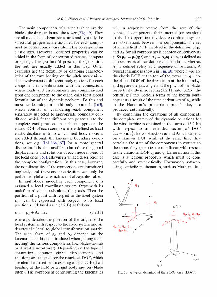
ARTICLE IN PRESS
y
O
q8 q9 q10 q11q12 q13
yG y
z
x
O
x
y
z
OG O
xG x
zG z
q1 q2 q3 q4q5 q6
q7
q14
Fig 20 A typical definition of the q DOF on a HAWT
MOL Hansen et al Progress in Aerospace Sciences 42 (2006) 285ndash330 307
The main components of a wind turbine are theblades the drive-train and the tower (Fig 19) Theyare all modelled as beam structures and typically thestructural properties are assumed for each compo-nent to continuously vary along the correspondingelastic axis However localized properties can beadded in the form of concentrated masses dampersor springs The gearbox (if present) the generatorthe hub are usually added in this way Otherexamples are the flexibility or damping character-istics of the yaw bearing or the pitch mechanismThe involvement of different body motions for eachcomponent in combination with the connectionswhere loads and displacements are communicatedfrom one component to the other calls for a globalformulation of the dynamic problem To this endmost works adopt a multi-body approach [165]which consists of considering each componentseparately subjected to appropriate boundary con-ditions which fit the different components into thecomplete configuration In such an approach theelastic DOF of each component are defined as localelastic displacements to which rigid body motionsare added through the kinematic boundary condi-tions see eg [161166167] for a more generaldiscussion It is also possible to introduce the globaldisplacements and rotations at each node instead ofthe local ones [153] allowing a unified description ofthe complete configuration In this case howeverthe non-linearities of the connections are introducedimplicitly and therefore linearization can only beperformed globally which is not always desirable
In multi-body modelling each component k isassigned a local coordinate system Oxyz with itsundeformed elastic axis along the y-axis Then theposition of a point with respect to the fixed systemrGk can be expressed with respect to its localposition rk (defined as in (321)) as follows
rGk frac14 qk thorn Ak rk (3211)
where qk denotes the position of the origin of thelocal system with respect to the fixed system and Ak
denotes the local to global transformation matrixThe exact form of qk and Ak depends on thekinematic conditions introduced when joining (con-necting) the various components (ie blades-to-hubor drive-train-to-tower) Depending on the type ofconnection common global displacements androtations are assigned for the restricted DOF whichare identified to either an existing elastic DOF (shaftbending at the hub) or a rigid body motion (bladepitch) The component contributing the kinematics
will in response receive from the rest of theconnected components their internal (or reaction)loads This operation involves co-ordinate systemtransformations between the components The setof kinematical DOF involved in the definition of qk
and Ak for all components is denoted collectively asq So qk frac14 qk(q t) and Ak frac14 Ak(q t) qk is defined asa mixed series of translations and rotations whereasAk is defined solely as a sequence of rotations Atypical example is shown in Fig 20 where q1ndashq6 arethe elastic DOF at the top of the tower q8ndashq13 arethe elastic DOF of the drive train at the hub and q7and q14 are the yaw angle and the pitch of the bladerespectively By introducing (3211) into (325) thecentrifugal and Coriolis terms of the inertia loadsappear as a result of the time derivatives of Ak whilein the Hamiltonrsquos principle approach they areproduced automatically
By combining the equations of all componentsthe complete system of the dynamic equations forthe wind turbine is obtained in the form of (3210)with respect to an extended vector of DOFuext frac14 u q
By construction qk and Ak will depend
on unknown DOF while at the same time theycorrelate the state of the components in contact sothe terms they generate are non-linear with respectto the unknown DOF uk and q Linearization in thiscase is a tedious procedure which must be donecarefully and systematically Fortunately softwareusing symbolic mathematics such as Mathematica
ARTICLE IN PRESSMOL Hansen et al Progress in Aerospace Sciences 42 (2006) 285ndash330308
are available which are strongly recommended Theprocedure is based on Taylorrsquos expansions of allvariables and retaining of first-order terms Alter-natively the extended version of (3210) can besolved directly through an iterative procedure ineach time step which can use the linearized solutionas a starting predictor
4 Problems and solutions in wind turbine
aeroelasticity
In the following section the use of aeroelasticcodes on wind turbine constructions includingstability studies will be illuminated mainly throughexamples
41 Aeroelastic stability
Wind turbines suffer from low structural damp-ing which can become critical under certain opera-tional conditions Most problems appear on theblades that receive almost 100 of the loading Inparticular the onset of stall plays a decisive role notonly on stall-regulated machines but also on pitch-regulated ones around rated conditions On theother hand the blades are made of compositematerials for which the knowledge on damping issubstantially inferior compared to steel or concreteconstructions The damping of composite structuresdepends on the ambient temperature So dependingon the season or the time during the day thestructural damping of the blades can decreasesubstantially Furthermore aging always degradesthe damping of composite structures There is adefinite need to increase structural damping andsignificant effort has been put recently on itsmodelling in composite structures as well as in theirappropriate design This is one direction of researchregarding the improvement of the stability char-acteristics of modern wind turbines see [168] for areview of the current developments Damping isrequired to suppress the onset of vibrationsgenerated by the unsteady aerodynamic loads thatinteract with the wind turbine structure First theaeroelastic modelling of wind turbines is consideredand then on this basis the aeroelastic stabilityproblem is formulated and the relevant availablemethods are reviewed
Aerodynamic modelling involves the calculationof the aerodynamic loads that also depend on thedynamics of the system The flap and lag vibrationsare interpreted by the incoming flow as a change in
the effective angle of attack indicating strongaeroelastic coupling All the currently availableaeroelastic tools for wind turbines use 2D dynamicairfoil data models such as the BeddoesndashLeishmannor the ONERA model They provide aerodynamiccoefficients as functions of the aerodynamic statevariables that satisfy appropriate dynamic equa-tions [17169] In either model the equations are 2Dand so they are applied on a strip-by-strip basismeaning that there is no interaction in the radialdirection This fits well with BEM modelling of theoverall aerodynamic analysis In fact the followingpresentation is referred to the BEM context sincemost existing stability models are based on it If apotential flow model is applied then the attachedpart of lift can be associated to potential lift whilethe rest is simply added [163] If the potential flowmodel is enhanced with a separation model thereshould be correlation on both aspects [58] How-ever the latter has not been applied yet inaeroelastic computations
By considering a blade section at a radial positionas shown in Fig 1 the local aerodynamic loadsacting on this section of the blade can be written asfollows since the lift is perpendicular and the dragparallel to the relative wind
py frac14 L sin fD cos f
pz frac14 L cos fthornD sin f
My frac14M eth411THORN
where L D are the lift and drag forces M is thepitching moment f is the local flow angle withrespect to the rotor plane Once the induced velocityhas been determined the local effective incidence aand relative flow velocity can be calculated as shownin Section 21 They will depend on the elasticdeformations and the velocities the rigid bodymotions and if appropriate orientation changes asin pitch and yaw variations In order to obtain aunified description of the coupled aeroelasticproblem a so-called aeroelastic finite element isdefined [170] which in addition to the elastic DOFthe aerodynamic state variables added For examplein the ONERA model there will be in total eightadditional DOF Because the dynamic equations forthe aerodynamic state variables only can be firstorder in time in order to produce a consistentcoupled system they can be differentiated as in[171] Therefore they can be assembled togetherwith the dynamic equations in the form of (3210)where the vector of the unknowns is further
ARTICLE IN PRESSMOL Hansen et al Progress in Aerospace Sciences 42 (2006) 285ndash330 309
extended to include the additional aerodynamicDOF Another approach used in [172] is tointroduce the modal expansion of the structuralDOF at stand still which better conditions thecoupled system
On the above basis it is possible to formulate theaeroelastic stability problem for wind turbinesWithin the context of linear theory stabilityboundaries are obtained by examining the evo-lution of small perturbations with respect to asteady state or a periodic solution acting asreference To this end the original equations arelinearized with respect to the reference state andthe resulting system solved with respect to thefluctuations
Methuref THORN eurouthorn Cethuref THORN _uthorn Kethuref THORN u frac14 Q (412)
where M C and K depend only on the referencesolution If the matrices do not depend on time(412) is reformulated into a first-order system
_y frac14 D ythorn b y frac14 u _un oT
(413)
The eigenvalue analysis of D provides the eigen-frequencies and damping of the system [173] This ispossible when the reference state corresponds to asteady solution as in the case of an isolated bladeHowever when analysing the complete windturbine configuration due to the rotation of theblades the reference state should correspond to aperiodic equilibrium state with reference to the rotorspeed which is assumed constant In this case thecorresponding theoretical framework is Floquetrsquostheory which for a large system is computationallyheavy [174] If the blades are identical and thenumber of blades NX3 which is the most frequentcase it is possible by means of multi-bladetransformation to eliminate the periodic coefficientsin the coefficients of (412) and therefore be ableto still use eigenvalue analysis [175] In this contextthe non-linear equations of the system are inte-grated in time until such a periodic state is attainedIn the case of an unstable situation because thetime domain response will contain significantcomponents in all of the basic eigenfrequencies ofthe system the reference state is obtained bytruncating the response so as to retain only its 1and Nrev components To this end all DOF in therotating system qm m frac14 1 NX3 are reformedqm frac14 q0 thorn qc cos cm thorn qs sin cm where cm frac14 Otthorn
eth2p=NTHORNethm 1THORN is the corresponding azimuth loca-tion Next the equations for the blade DOFs are
rearranged by applying the operators eth1=NTHORNPN
mfrac141
eth THORN eth2=NTHORNPN
mfrac141eth THORN cos cm and eth2=NTHORNPN
mfrac141eth THORN
sin cm This is performed after the periodic solutionhas been obtained over one period of rotation Theresulting equations will be in the non-rotating frameand contain only higher harmonics (3rev andhigher) By averaging over one period the finalconstant coefficient system is obtained in the formof (413) For the blades y will contain thecorresponding q0 qc and qs DOF and their timederivatives for both the purely structural and theaerodynamic DOF [171] In the above approach it isworth noticing that the averaging procedure willforce the reference state to appear in the equationsThis is an important aspect when dealing with non-linear systems
Stability of wind turbines has been consideredsystematically in Europe in the late 1990s [176] whiletoday there is an on-going activity under the EUfunded project STABCON Several linear stabilitytools have been produced along the lines describedabove and good correlation has been obtainedamongst the different codes see [177] and thereferences cited Inevitably linear theory is approx-imate so the results it produces are subject to crosschecking Clearly flutter measurements are difficultto obtain because of the involved risk therefore it isindispensable to rely on theoretical developmentswhich will be discussed in the next section
42 Aeroelastic coupling linear vs non-linear
formulations
Linearization of the aeroelastic equations cer-tainly offers computational efficiency However it isnot always appropriate For the structure lineartheory requires that the deformations and displace-ments are small an assumption not always validFor the aerodynamics and its coupling with thestructure linearization will suppress some depen-dencies involved in (411) and therefore influencethe estimation of the aerodynamic damping In thisconnection the use of semi-empirical unsteadyaerodynamic models introduces still unresolveduncertainties Furthermore there are cases in whichthe multi-blade transformation is not applicable egwhen blades are non-identical or when the rota-tional speed varies
Retaining fully the non-linearities of the aero-elastic problem has the following consequences thestructure is considered at its deformed state thecoupling conditions among the components are
ARTICLE IN PRESSMOL Hansen et al Progress in Aerospace Sciences 42 (2006) 285ndash330310
taken in their full form and the aerodynamicequations are not simplified The last point isimportant with respect to the best possible estima-tion of the aerodynamic damping within themargins offered by the semi-empirical models usedin the currently available aeroelastic tools In thisrespect multi-body analysis which has beenadopted in most of the existing stability tools[161178ndash181] offers this option by constructionprovided that the structural model considers theconstruction at its deformed state and the codetakes this into account in the definition of the localaerodynamics
Under such conditions the information of thestability characteristics of the wind turbine arecontained in the time signals of the loads calculatedthrough a non-linear time domain simulation Thereexist two types of methodologies for retrieving thisinformation the one is based on the work-basedapproach [176] while the other is using signal-processing techniques In the work-based methodany mode shape is excited and loads are recordeduntil a steady periodic state has been reached Thenthe aerodynamic damping is estimated by the workof the aerodynamic loads over the last period underthe assumption that there is no energy interchangebetween the modes through the aerodynamic loadsIn the signal processing approach the system isharmonically excited for a finite duration Then thetransient response following the abrupt terminationof the excitation is recorded wherefrom the aero-elastic damping and frequency of the specific modeare determined There are two different methodsboth well documented in the literature [182ndash184]that can be used the moving block method and themethod of Hilbert transform The moving blockmethod is a FFT based method commonly used inrotorcraft applications [182184] The transientresponse amplitude is computed on a block of datausing a FFT calculation The block is then movedforward by a single point in time and the computa-tion of the transient response amplitude is repeatedThe linear fit for the slope of the natural logarithmof the sequence of response amplitudes in time(peak plot) provides the damping (Fig 21) In theHilbert method the transient response y(t) and itsHilbert transform ~yethtTHORN are used to define theenvelope signal AethtTHORN frac14
ffiffiffiffiffiffiffiffiffiffiffiffiffiffiffiffiffiffiffiffiffiffiffiffiffiy2ethtTHORN thorn ~y2ethtTHORN
p[183184]
For a transient response typical of a viscouslydamped system a line can be fitted to the logarithmof this envelope The slope of this line as in the caseof the moving block method gives the damping
(Fig 22) Comparing the two it has been found thatthe Hilbert method has certain advantages over themoving block method In particular the Hilbertdamping analysis provides an estimate of thedecaying envelope signal so it can be used inassessing the non-linear damping characteristics ofa mode Therefore it is not limited by the assump-tion of the viscous damping as the moving blockmethod does Moreover experience has shown thatthe Hilbert method is more efficient in calculatingthe damping of spectrally close modes [163]
43 Examples of time simulations and instabilities
In this section the challenges in aeroelastic design ofwind turbine rotors will be addressed and in particularthe phenomenon of aeroelastic instability of windturbine rotors will be explored by showing examplesof simulation results on a wind turbine design
Back from the beginning of development ofmodern wind turbine rotors in the late seventiesthere has been concern about the problems thatcould arise due to aeroelastic instability In parti-cular the use of the stall regulation principle wasuncertain as it was foreseen that a flapwiseinstability (so-called stall flutter) would occur whenoperating in the stall region due to the negativeslope of the CL vs a curve However it turned outthat the flapwise instability during operation in stallwas not the most critical problem but instead theedgewise instability resulting in edgewise bladevibrations The first experimental evidence of thisinstability was seen in the mid nineties and initiatedconsiderable research activities in order to explorethe phenomenon and provide practical solutionsBelow is mainly focused on this instability as thisserves as a good example to illustrate the problem ofaeroelastic instability in more general terms
In the more recent wind turbine designs theregulation of the turbines has shifted from stallregulation to pitch control where the operationalrange for the flow over the blade moves to low angleof attack at high wind and thus away from the stallregion This has almost removed the instabilityassociated with stall during operation but it is stillso that the edgewise blade modes are aerodynami-cally low damped on the pitch regulated turbines
A major instability problem on the modernturbines is seen when the rotor is parked or idlingat very low RPMs at wind speeds above stop windspeed which typically is around 25ms Again it istypically edgewise dominated instability problems
ARTICLE IN PRESS
3540
4550
tim
e (s
ec)
-35
E+
06
-3E
+06
-25
E+
06
-2E
+06
-15
E+
06
-1E
+06
tower top tilt bending moment (Nm)
12
34
freq
uenc
y (H
z)
0
5E+
08
1E+
08
15E
+08
2E+
08
25E
+08
3E+
08
FFT of the tower top tilt bending moment (Nm)
Δt
data
19
190
5
191
191
5
192
192
5
193
193
5
194
00
51
15
22
53
t (se
c)
-ζ Ω
n
log of response amplitude
Fig21Schem
aticdescriptionofthemovingblock
dampinganalysis
MOL Hansen et al Progress in Aerospace Sciences 42 (2006) 285ndash330 311
ARTICLE IN PRESS
-15e+06
-1e+06
-500000
0
500000
1e+06
15e+06
2 4 6 8 10 12 14
tow
er to
p til
t ben
ding
mom
ent (
KN
m)
time (s)
transient signalenvelope signal
envelope signal exp fit
Fig 22 Envelope signal calculation of the tower top tilting moment transient response using the Hilbert transform method for the same
signal as in Fig 21
1000
800
600
400
200
0
-2000 50 100 150 200 250 300
Time [sec] Time [sec]
ED
GE
WIS
E B
LA
DE
RO
OT
MO
ME
NT
[U
NC
AL
IBR
AT
ED
]
ED
GE
WIS
E B
LA
DE
RO
OT
MO
ME
NT
[U
NC
AL
IBR
AT
ED
]
EDGEWISE BLADE VIBRATION INSTABILITY EDGEWISE BLADE VIBRATION INSTABILITY--MEASUREMENT
1000900800700600500400300200100
0-100
200 210 220 230 240 250 260
Fig 23 Measured edgewise blade root moment on a stall regulated rotor at high wind Detail of the time track to the right
MOL Hansen et al Progress in Aerospace Sciences 42 (2006) 285ndash330312
related to stall of the blade A simulation examplewill be shown later to illustrate this problem
Finally the flutter instability will be addressed Itseems that the increased up scaling of the turbineshas led to rotor and blade designs where the flutterspeed is not so far away from normal operationalspeed Also this instability will shortly be illustrated
431 Edgewise blade vibration instability
As mentioned above the first experimentalevidence of this instability was seen in the mid
nineties on stall-regulated rotors with a diameter of35ndash40m An example is presented in Fig 23 and it isseen that the amplitude of the edgewise blade rootmoment (which at steady conditions vary sinusoidalwith 1p due to the gravity) increases 2ndash3 times dueto instability during operation in stall The experi-mental evidence of the edgewise instability led toconsiderable research on this subject and a majorEuropean project lsquolsquoPrediction of Dynamic Loadsand Induced Vibrations in Stallrsquorsquo funded by the EUwas carried out in the period from 1995ndash1998 [176]
ARTICLE IN PRESSMOL Hansen et al Progress in Aerospace Sciences 42 (2006) 285ndash330 313
The origin of the instability is simple If a rotatingairfoil section is harmonically translated along anaxis xB and the direction of this axis yRB relative tothe orientation xR of the rotor plane is varied theaerodynamic damping coefficient for the sectionvaries considerably see Fig 24 from [185] For lowyRB which means in-plane or edgewise vibrationdirection the damping coefficient is negative even atlow wind speed For vibrational directions close to901 which corresponds to out-of-plane or flapwisedirection the damping coefficient is strongly depen-dent on the inflow wind speed It is highly damped
Fig 24 The aerodynamic damping coefficient c_xx_b for a rotating a
different inflow velocities from [185]
Fig 25 Damping characteristics computed for a rotating isolated bl
at low wind but close to zero or negative damped athigh wind
On a complete rotating blade the direction ofvibration depends on the structural design of theblade as well as of the complete turbine structureThe movement of the tip section of the blade willnow no longer necessarily be along a straight lineHowever typically the tip section of the blade in thefirst flapwise mode will be on a path almostperpendicular to the rotor plane and in the 1stedgewise mode it will almost be in-plane It is thusexpected that the basic damping characteristics of
irfoil section as function of vibration direction yRB and at three
ade using the linear aeroelastic stability tool HAWCStab [186]
ARTICLE IN PRESSMOL Hansen et al Progress in Aerospace Sciences 42 (2006) 285ndash330314
the whole blade will be comparable with thecharacteristics of a single airfoil section Using thelinear stability tool HAWCStab the dampingcharacteristics for a rotating blade can easily bederived and the computed damping characteristicsfor a rotating 19m blade (500 kW rotor) corre-sponding to the blades of the rotor where theexperimental instability was shown in Fig 23 areshown in Fig 25 from [186] It is seen that thedamping for the first flapwise mode varies fromhighly positive values at low wind speed and tovalues close to zero at 14ms and then increasingslightly at higher wind speeds It should be notedthat the influence of using unsteady blade sectionaerodynamics is shown (modelled with the BeddoesLeishman model in the present case) and that thishas considerable influence on the aeroelastic damp-ing Generally the unsteady aerodynamic effectsincrease the damping The damping for the firstedgewise mode is seen to decrease gradually withincreasing wind from being slightly positive at lowwind to slightly negative at high wind Finally itshould also be noted that the damping shown is thetotal damping including the structural dampingwhich in the present case is around 2 for the firstflapwise mode and 3 for the first edgewise mode
The final step in model complexity is nowobtained by going to a full aeroelastic model ofthe turbine comprising the dynamics of the shaftthe nacelle and the tower The aeroelastic stability
Fig 26 Aeroelastic damping computed with the aeroelastic stability HA
speed
results using HAWCStab is for the complete windturbine see eg Fig 26 from [186] showing theaeroelastic damping for the first 10 mode shapes(numbered from lowest frequency) It is seen thattwo mode shapes are negatively damped at highwind speed and that one mode shape is close to zeroand slightly negatively damped at the highest windspeed For comparison time simulations with theaeroelastic code HAWC [187188] is performed onexactly the same turbine model at a wind speed of 8and 16ms respectively in order to see if theinstability at high wind speed predicted by the linearstability tool can be confirmed by the HAWCmodel with non-linear aerodynamics The com-puted edgewise blade root moment shown in Fig 27confirm the instability at high wind and comparesvery well with the measured instability shown inFig 23 It is thus demonstrated that the edgewiseinstability problem can be predicted in both timesimulations and using linearized stability analysisHowever as will be demonstrated below theedgewise vibration instability is much more complexthan just edgewise vibrations of the individualblades but comprises the dynamic characteristicsof the whole turbine This understanding is vital forthe development of design solutions preventing theinstabilities
In order to analyse the instability in more detailsthe use of parallel aeroelastic time simulations on aturbine with a stiff structure is made In this case the
WCStab [186] Three modes have negative damping at high wind
ARTICLE IN PRESSMOL Hansen et al Progress in Aerospace Sciences 42 (2006) 285ndash330 315
loads on the different components will mainlyreflect the direct load input from the externalaerodynamic forces and from gravity forces Itshould be mentioned that the simulations areperformed at two average wind speeds of 8 and16ms respectively and with a turbulence intensityof 12
A power spectral density analysis of the simulatededgewise blade root moment shows a distinct peakat 307Hz which is close to the frequency of the firstedgewise mode for a single rotating blade which is319Hz see Fig 28 The response at 16ms of theflexible turbine at this frequency is seen to be severalorders of magnitude bigger than the response of thestiff turbine indicating an instability situationSomewhat the same tendency is seen at 8ms but
Fig 28 Comparison of power spectra of edgewise blade root momen
Fig 27 Time simulation with the aeroelastic code HAWC on a 50
with considerable less difference between the re-sponse of the stiff and flexible turbine indicating lowdamping but not an instability
Analysing further the results of the stabilityanalysis with HAWCStab as shown in Fig 26 itcan be derived from the results of the model that thethree mode shapes that are negatively damped orvery low damped at 16ms are
t fo
0 k
mode no 1 with frequency 077Hz and damping605
mode no 3 with frequency 093Hz and damping433
mode no 7 with frequency 273Hz and damping
159
r a flexible and a stiff turbine respectively at 8 and 16ms
W stall regulated rotor at two wind speeds 8 and 16ms
ARTICLE IN PRESSMOL Hansen et al Progress in Aerospace Sciences 42 (2006) 285ndash330316
The numbering in HAWCStab of the modes iswith increasing mode number with increasingfrequency starting with the lowest frequency Modeno 1 and no 3 are both modes where lateral towerbending is the main motion together with edgewisebending of the three blades and torsion of the mainaxis The edgewise movement of the blades are all inphase and the difference between the two modes isthe direction of the edgewise bending relative to thetower bending Comparing again the results of thelinear stability analysis with the time simulationresults the instability of the lateral tower bendingdominated modes is confirmed by the spectra of thetower top and tower bottom lateral bendingmoments Figs 29 and 30 A distinct peak at
Fig 29 Comparison of power spectra of tower top lateral moment
Fig 30 Comparison of power spectra of tower bottom lateral mome
079Hz is seen in both tower top and tower bottomspectra at 16ms and this peak cover probably alsoa considerable content at the 093Hz which was thefrequency of mode no 3
It can be noticed that the HAWCStab results donot contain an unstable mode with a frequencyaround 307Hz (the edgewise instability) as seen inthe time simulation results However mode no 7 isin fact the response on the non-rotating turbinestructure from the edgewise vibrations at 307HzThe edgewise vibrations in the present case is a so-called backward whirling edgewise mode wherethere is a phase shift of 1201 between the movementof the blades This whirling mode results in shaftand tower bending but with a frequency shifted 1p
for a flexible and a stiff turbine respectively at 8 and 16ms
nt for a flexible and a stiff turbine respectively at 8 and 16ms
ARTICLE IN PRESSMOL Hansen et al Progress in Aerospace Sciences 42 (2006) 285ndash330 317
(p is the rotational frequency) up and downrespectively compared with the frequency in therotating system As 1p in the present case is 045Hza peak in the spectra of tower bending at afrequency of around 307ndash045Hz equal to 262Hzis expected which is also seen in Figs 28 and 29However in the HAWCStab results a slightlyhigher frequency 273Hz was seen for this mode
The presented example of the edgewise bladevibration instability has shown that the low aero-dynamic damping of an airfoil section undergoing amotion along a path close to the chordwise directioncan cause instability of quite different modes on theturbine at the same time The design challenges withthe objective to minimize the influence of lowaerodynamic damping or instability are thus big aseg changes in tower design could lead to egedgewise vibrations on the rotor A number ofdifferent methods to reduce the risk for edgewisevibrations on stall-regulated turbines have beeninvestigated [176186] and comprises eg changes ofthe stalling characteristics of the airfoils by so-calledlsquolsquostall stripsrsquorsquo as well as structural design of theblades to achieve optimal vibrational directions
432 Instability problems of parked rotors
The turbines are normally designed to operate upto a certain maximum wind speed and above thiswind speed the turbines are shut down In thestopped conditions the rotors can be completelyparked or they can idle with low rotational speeddepending on the actual design of the controlsystem As part of the certification of the turbineit must be shown that the turbine can withstand the
Fig 31 Simulation of a parked rotor at 50ms and a yaw error of 601
power spectrum of the same signal to the right
wind loads at extreme wind speed conditions withparked rotor and the wind coming from anydirection in the case that the yawing system of theturbine is not functioning
As an example the simulation of a rotor parkedat a wind speed of 50ms and a yaw error of 601 isshown in Fig 31 The turbine is the same as aboveand the time track of the edgewise blade rootmoment indicates low damping as the amplitudesvary much in time To the right in Fig 31 is shown apower spectrum of the same signal and it shows thatthe blade mainly vibrates in two modes mode 3 at afrequency of 093Hz which was described aboveand the first edgewise blade frequency at about319Hz For the present inflow direction thevibrations are not unstable but it has to bedocumented for all inflow directions
433 Flutter instability
The last example of an instability is flutter This isa well-known instability from the aircraft industrybut has not yet been a problem on wind turbinesand has probably not been seen on commercialturbines However with the increasing size of theblades it seems that the flutter speed decreases dueto increasing structural flexibility of the blades andnot least the torsional frequency decreases There-fore it is a good idea to include a flutter speedcalculation in the design verification for eg 50mblades and above
Flutter involves two DOF of the blade torsionand translation The flutter speed decreases whenthe frequency of these two DOF approach eachother For 50m blades the frequency of the first
Time track of the edgewise blade root moment to the left and a
ARTICLE IN PRESSMOL Hansen et al Progress in Aerospace Sciences 42 (2006) 285ndash330318
flapwise mode is typically slightly below 1Hz andthe frequency of the first torsional mode willtypically be in the range from 5 to 8Hz Howeverit has been seen that the flutter instability can occurby a coupling of the second flapwise mode and thefirst torsional mode of the blade and of course this isalso a reason for a decreasing flutter speed on thebigger blades Another important design parameterfor the flutter instability is the centre of mass in theblade sections relative to the centre of the elasticaxis As the centre of mass moves away from theelastic axis in the direction of the trailing edge theflutter speed decreases
An example of a simulated flutter instability isshown in Fig 32 The blade does not represent anindustrial blade but has selected structural para-meters which give a rather low flutter speed Thesecond flapwise mode for the blade is slightly above2Hz and the first torsional frequency is around6Hz Further the centre of mass is positioned 10of the chord length behind the elastic axis Theexample is mainly intended to show the character-istics of the flutter instability which is completelydifferent from the instabilities that have been seenso far In the simulation the rotor is free to speed upas the generator is disconnected When the flutterspeed is reached the instability develops within 1ndash2 sand this is completely different from eg theedgewise blade instability that can build up over aminute or more This characteristic means the bladeprobably will be damaged immediately if the flutterspeed is reached A further consequence of this fastdevelopment is that the flutter can occur at a lowerrotational speed of the rotor if there is a yaw errorThis is demonstrated in the right part of Fig 31
Fig 32 Example of flutter instability on a 50m test blade where the r
right there is a yaw error of 501
where there is a yaw error of 501 Here therotational speed at flutter instability is 13 lowerthan if there is no yaw error and the wind speed isjust 8ms If the for example the yaw error of 501occurred at around the stop wind speed of 25msthe rotational speed at the flutter instability woulddecrease even further
5 Present and future developments of aeroelastic
models
The improvement of existing aeroelastic codesand the development of new aeroelastic models arehighly influenced by the design trends of new windturbines and trends in the siting of the turbinesbecause this determines the needs for new capabil-ities of the models
51 Areas with influence on the development of
aeroelastic models
511 Influence of up-scaling
So far the most important design trend has beenthe up-scaling which within the last 10 years hasincreased the maximum size of the mass producedturbines with a factor of 10 from about 500 kW witha rotor diameter of about 40m to 5MW turbineswith a rotor diameter of 120m The newest turbinesare all pitch controlled with variable speed andtypically with some type of cyclic pitch for loadalleviation An accurate modelling of these newflexible turbines has increased the requirements tosimulate complex coupled modes where the inte-grated flexibility of the tower of the drive train andof the blades and in interaction with the control is
otor is free to speed up To the left normal inflow whereas to the
ARTICLE IN PRESSMOL Hansen et al Progress in Aerospace Sciences 42 (2006) 285ndash330 319
important Also non-linear effects from consider-able deflections of the blades and the tower arebecoming important and the aeroelastic stabilitymust be predicted with a good accuracy Sometypical frequencies for a 5MW turbine could be
First tower bending frequency
02ndash025Hz
First flapwise frequency
08ndash10Hz
First edgewise frequency
09ndash11Hz
First blade torsional frequency
50ndash70Hz
The decrease in the fundamental turbine frequen-cies arising from the up-scaling has the effect thatexcitation from the turbulent inflow has increased asthe power spectrum of the turbulence peaks ataround 005Hz
512 Siting of the turbines
The major part of all new turbines is placed insmall or bigger groups and in some cases in windfarms with more than 100 turbines This means thatwake operation is part of the inflow conditionswhich has to be simulated in the derivation of thetotal design loads of the turbines Load alleviationby cyclic or individual pitch controls is importantfor such inflow conditions and the aeroelasticmodels should be suited for this
Still the major part of turbines are set up on landbut the offshore part will increase at least if a 5ndash10years interval is considered On land the best siteshave been used in many countries and thereforemore and more complex sites will be used Thismeans that rather complex inflow situations must bemodelled as for example complex shear and non-uniform turbulence over the rotor disc
513 Future trends in turbine design and siting
It seems that the speed of up-scaling might beslowed down for some years as the industry wantsto be more focused on turbine reliability One wayto improve this is to have the individual turbinemodels on the market for more years than seen inthe past
However the increasing offshore developmentwill support the up-scaling tendency as the tran-sport and erection of big turbine components is nolonger a major problem Further the higherfoundation costs offshore will also support the up-scaling trend
Extending the possible offshore sites to deeperwater new foundation types typical with multipleframes will be developed and the aeroelastic codes
should be able to handle these structures A furtherstep in the offshore development is the floatingturbines either as single floating turbines or moreturbines on the same floating frame
Finally the offshore market could have the effectthat the two bladed turbine with a teetered down-wind rotor again will be considered as an alternativeto the three-bladed machines The main barrier forthe development of two bladed turbines has beenthe low frequency noise from the blade passage ofthe tower shadow This will be of less importanceoffshore as the noise restrictions are much lowerhere
52 Areas of development in present and new codes
Influenced by the continuously increasing require-ments to the capabilities of the aeroelastic models asdescribed above existing models are being furtherdeveloped and improved and new codes are writtenBelow some important areas of development will bediscussed
non-linear structural dynamics
calculation of induction and its dynamics
wake operation
derivation of airfoil data for aeroelastic simula-
tions
complex inflow
aerodynamics of parked rotors and
off shore turbines including floating turbines
521 Non-linear structural dynamics
So far almost all aeroelastic codes have containedthe model assumptions of small deformations androtations but the increased flexibility of the turbineshave made uncertainty about the validity of thisassumption for the new designs The influence ofnon-linear effects on the dynamic response of aturbine was treated in a recent paper [189] anddifferent effects were considered For examplecharacteristics (frequency and damping) of the firstedgewise mode will typically change as function ofincreased flapwise deflection because the edgewisebending will couple more and more with thetorsional mode of the blade Besides increasedinfluence to non-linear effects from the flexibilityof the turbine components the new foundationsused offshore and in particular floating foundationscan contribute significantly to big deflections andrelated non-linear effects
ARTICLE IN PRESSMOL Hansen et al Progress in Aerospace Sciences 42 (2006) 285ndash330320
To overcome this uncertainty about the impor-tance of non-linear effects a few new non-linearaeroelastic codes have now been developed Siemenswind power has developed a non-linear codeBHawC based on co-rotaing elements [190] whilethe new non-linear code HAWC2 [191] developedby Risoe is based on multibody dynamics
The trend of including non-linear effects willcontinue in the future and codes based on modalexpansion techniques will be developed to includemore modes as eg the blade torsional mode
522 Calculation of induction and its dynamics
The unsteady aerodynamic air loads are directlydependent on the computed induction at the samepoint on the blade through the angle of attackTherefore an accurate prediction of induction is ofcrucial importance
As the rotor disc has become bigger and biggerrelative to the scales in the turbulent inflowincreasing variation in inflow conditions over therotor disc are seen Wind shear contributes to thisvariation in inflow The inflow variations results inlikewise considerable variation in the loadingexpressed through the local thrust coefficient CTlocal
over the rotor disc and thus also in induction Theinduction is therefore even in normal operationhighly dynamic and the induction model should beadapted to these conditions As an example Fig 33
Fig 33 Example of dynamic loading at a point close to the tip of a b
(reproduced from [192]) shows the variation of thelocal thrust coefficient at the outer part of the bladeon an 80m diameter turbine in normal operation
Another source contributing to the load varia-tions and thus to the dynamic induction is theeigenmotion of the blades This part is alsoincreasing due to up-scaling and due to the moreflexible designs As an example a blade with aflapwise frequency of 1Hz as mentioned above andvibrating with an amplitude of 1m will experience arelative velocity component perpendicular to thechord of around 76ms in maximum This valuecan directly be compared with the variations ininflow and is thus considerable Different develop-ments to improve the computation of inductionhave been seen One type of modelling is thecoupling of a numerical actuator disc model to thestructural part of the aeroelastic model So far suchmodels have mainly been used to verify the accuracyof BEM modelling As an example the aeroelasticcode HAWC at Risoe with a BEM-type inductionmodelling in the standard version has been devel-oped in another version HAWC-3D where theinduction is computed with a 3D actuator discmodel and used eg to investigate the accuracy ofyaw modelling [142193] see Fig 34 from [142] Inthe coming years aeroelastic codes coupled to anactuator disc or actuator line model for computa-tion of induction will certainly be further developed
lade on an 80m diameter turbine in turbulent wind from [192]
ARTICLE IN PRESS
Fig 34 Influence of yaw on the local inflow angle The curves show the difference in local inflow angle at yawed operation at 451
compared with non-yawed operation The HAWC model has a BEM induction model HAWC-3D a 3D actuator disc model and
EllipSys3D is a full 3D NavierndashStokes simulation from [142]
MOL Hansen et al Progress in Aerospace Sciences 42 (2006) 285ndash330 321
but probably mainly used for research and forverification of simpler codes and not so much in theaeroelastic codes used by the industry due to themuch longer simulation time
However besides a direct coupling of an actuatordisc or line method to an aeroelastic code in order tocompute the induction at each time step there areother ways to utilize the capabilities of an actuatordisc model One example is to compute theinduction characteristics of a rotor within its windspeed operational interval with an actuator disc andthen afterwards use these quasi-steady inductioncharacteristics in aeroelastic simulations for therotor The BEM method in the new HAWC2aeroelastic code developed at Risoe has beenimplemented in such a way that this method canbe used The method is shortly first to compute thelocal induction as function of local loading for theactual rotor in a number of calculation points ethn mTHORN over the rotor with an actuator disc
aethrn ymTHORN frac14 f CT rn ymeth THORNeth THORN
Afterwards these induction functions are then usedin the BEM method during time simulations on therotor instead of the unique single relationship from1D momentum theory CT frac14 4aeth1 aTHORN
In fact one of the main deficiencies of the BEMmethod is that this induction formula concerns thewhole rotor disc Deviations are seen in regions withconsiderable radial variation in the loading whichmeans in the tip or root region Another examplewhere the momentum induction formula does nothold is if the rotor disc is not plane eg conedrotors or rotors where the blades bend considerably
523 Wake operation
Most turbines are now set up in clusters or windfarms and this means that such turbines in part oftheir lifetime operate in wake from one or moreturbines In the international standard for design ofturbines IEC 61400-1 [2] the increased loading fromoperation in wake can be taken into account byusing an increased effective turbulence whichdepends on a number of parameters in theconsidered wind farm such as eg wind turbinespacing However it has turned out that in caseswhere more detailed knowledge of the increasedloading on the different turbine components fromwake operation is needed another more detailedaeroelastic modelling is needed than just increasingthe turbulence One such aeroelastic modelling hasbeen developed over the past few years [194195]The main components in the modelling is (1)
ARTICLE IN PRESSMOL Hansen et al Progress in Aerospace Sciences 42 (2006) 285ndash330322
computation of the wake deficit from the up-streamturbine with an actuator disc model (2) meanderingof this deficit from the big scales in the turbulenceand (3) additional turbulence within the wake Oneof the advantages of this new modelling comparedto the method using an effective turbulence is thatboth the mean yaw loads as well as the yawdynamics compare well with measurement Fig 35from [194] shows the loads as function of winddirection and full wake operation at a direction ofaround 2101 The highest mean yaw loads occur inhalf wake operation at around 1951 and 2201Recently the wake resulting from the interaction ofseveral turbines in a row was computed in [196] bycombining large eddy simulation of the NS equa-tions with the actuator line methodology
Fig 35 Measured and simulated loads at 8ms (crosses and full lines)
wake operation (full wake at around 2101 on x-axis) using a new aeroel
meandering from [194]
It is expected that the more detailed aeroelasticmodelling of wake operation will be developedconsiderably in the coming years because suchmodelling is necessary for the development ofadvanced control algorithms adapted for loadreduction in wakes The development of the newdetailed models can be in the direction like themodel described above but also using actuator linemodels or full 3D rotor models to compute the wakecharacteristics which can be fed into an aeroelasticsimulation
524 Derivation of airfoil data for aeroelastic
simulations
The airfoil data used in aerodynamic and aero-elastic simulations are of crucial importance for the
and at 10ms (squares and dashed lines) on a 80m rotor during
astic wake simulation method taking into account the wake deficit
ARTICLE IN PRESSMOL Hansen et al Progress in Aerospace Sciences 42 (2006) 285ndash330 323
accuracy of such simulations This was clearly seenin the result of the NREL blind test [137] where thedifference in the airfoil data used in the individualsimulation models probably were the most signifi-cant factor for the big variation between the outputof the different simulations However it should benoted that this result is not a representativeindicator of the uncertainty in the industry onaerodynamic and aeroelastic results on new turbinesas considerable experience has been learned fromolder rotor designs in order to adapt airfoil data setsso that computed rotor power and loads comparewell with measurements The drawback is that thisintroduces conservatism in the design and forexample can hinder the use of new airfoils There-fore methods and models to derive or correct airfoildata to be used in aeroelastic simulations have beena key issue for many years in the wind energyresearch community and will also be it in the nearfuture 2D wind tunnel airfoil data has so far beenthe common starting point to set up an airfoil dataset for simulations In order to correct for so-called3D flow effects and rotational effects some kind ofcorrection is typically applied [19ndash21197] Thecorrections reflect the increased lift and drag thatwas measured on different rotors in field rotormeasurements performed 10ndash15 years ago [198199]Full 3D CFD rotor computations later confirmedclearly the tendencies of the 3D flow effects androtational effetcts in the form of increased lift in theblade root region but also increased drag [137ndash139]
With the possibility of running full 3D simula-tions on a rotor a new source for derivation of 3Dairfoil data sets for input in aerodynamic and
2
18
16
14
12C1
1
08
06
040 5 10 15 20 25 30
r=14r=28r=42r=56r=69r=89r=94r=97
35 40α
Fig 36 Extracted 3D airfoil data in the form of CL CD data as functi
rotor computation Figure from [202]
aeroelastic codes has emerged Methods to extractthe airfoil data from 3D rotor computations havebeen developed [200201] One example of such aderived airfoil data set is shown in Fig 36 from[202] where a considerable increased maximum lifton the inboard stations are seen Within the nextfew years it is expected that a considerable effortwill be on further development of the methods toextract airfoil data from 2D wind tunnel data aswell as 3D CFD rotor data So far the CFDcomputations have mainly been used to extractquasi-steady data but they will in the future also beused to tune the parameters in the dynamic stallmodels
525 Complex inflow
Wind turbines are often set up in so-calledcomplex terrain which means some kind ofmountainous terrain because the wind potential isgood at such places However the consequence isthat the inflow conditions can vary considerablyfrom turbine to turbine due to local variations ofthe terrain As a result extreme wind shear has beenseen to occur over the rotor disc of turbines placedin such terrain and likewise the turbulence intensitycan be extremely high
The fast development of CFD codes has nowmade it possible to simulate the flow in detailsover the terrain spanned by a wind farm in suchcomplex terrain The flow data in the form of windshear and turbulence can be used as input inaeroelastic simulations There is thus a basis for asimulation tool to micro site turbines not only withrespect to energy production but also loads is
Cd
r=14r=28r=42r=56r=69r=89r=94r=97
α
05
045
04
035
03
025
02
015
01
005
00
5 10 15 20 25 30 35 40
on of angle of attack at different radial stations from a 3D CFD
ARTICLE IN PRESSMOL Hansen et al Progress in Aerospace Sciences 42 (2006) 285ndash330324
expected Thus type of modelling is certainly ofhigh interest for the wind turbine industrybecause considerable costs to repair turbines dueto extreme inflow conditions have been experiencedin the past
526 Aerodynamics of parked rotors
It is a common procedure to shut the turbinesdown at high wind typically at wind speeds in therange from 20 to 25ms Ultimate loads on parts ofthe wind turbine can occur during standstill condi-tions at very high wind speed whereas ultimate loadson other components will occur during operationbelow the stop wind speed
The aerolelastic codes are therefore also used tocompute the turbine response during standstillconditions and it is particularly the computationof the aerodynamic loads on the blades that isuncertain This is due to the requirement that theloads on the parked rotor shall be investigated withthe wind from all directions The models musttherefore be able to compute aerodynamic loads forangle of attacks in the complete range from ndash180o to180o Furthermore the inflow is turbulent so that itis highly unsteady aerodynamic loads and a severecomplication is that some inflow conditions oftenlead to instability with the blade vibrating in a modewith negative aerodynamic damping In a recent EUfunded project lsquolsquoKNOWBLADErsquorsquo different CFDcodes were used to explore some basic character-istics of the blade standstill aerodynamics [115]Because of the complexity of the aerodynamics it isalso believed that the use of CFD will be the mainpath to explore the standstill aerodynamics in thecoming years
Fig 37 Different support struc
527 Offshore turbines including floating turbines
Presently there are considerable research anddevelopment efforts on adapting aeroelastic modelsto simulate offshore wind turbines mounted on asub-structure standing on the sea-bed see Fig 37from [203] or on a floating foundation
Different approaches are seen in this develop-ment One line is characterized by a completeintegration of the standard aeroelastic model ofthe turbine with a hydroelastic model of the sub-merged supporting structure including the hydro-dynamic loads the wave loading and the soil forceson the part of the support structure in the sea bed[190191] In both these models the completestructure is described with finite elements and withengineering sub-models for computation of thehydrodynamic loads
Another line of modelling is to couple alsquolsquostandardrsquorsquo aeroelastic model to a separate modulesimulating the supporting structure including waveloads and hydro loads This approach has beenpresented by Repower [204] where the Flex5aeroelatic code is coupled with a standard packageASAS for computations of wave loads on off shorestructures In the third development line the mainidea is also to use a lsquolsquostandardrsquorsquo aeroelastic code andthen couple it to a super element of the foundationThis approach has been presented by Vestas [203]where the foundation is modelled with a finiteelement model but then decomposed to a superelement using the CraigndashBampton sub-structuringscheme Considerable efforts on further develop-ments of the aeroelastic models for off shoreapplications will be seen within the next years andwith more emphasis on deeper water installations
ture concepts from [203]
ARTICLE IN PRESSMOL Hansen et al Progress in Aerospace Sciences 42 (2006) 285ndash330 325
6 Discussion
On a wind turbine there is a strong couplingbetween the aerodynamic loads and the time-dependent structural behaviour of the constructionStatically a blade might change its twist and thus theangle of attack when deflected But also the anglesof attack are changed when the blades have avelocity relative to the fixed ground For instance ifthe tower is moving upstream and everything else isstiff it will be felt by the blades as an increased windspeed and thus higher angles of attack will bepresent along the blades The aerodynamic responsewill depend on how the lift and drag vary with theangle of attack In stall the lift will decrease yieldinga possible instability whereas for attached flow thelift will increase and thus creating a higher load seenby the blade opposite the movement indicatingstability On a real wind turbine not only the toweris vibrating but all other components as well whichdirectly feeds back to the angle of attacks and thusthe loads that again alter the motion To simulatethe aeroelastic response of a wind turbine a non-steady structural model including the inertia mustbe made Two methods ie the method of virtualwork applied on modal shape functions and theFEM are addressed To evaluate the aerodynamicloads the BEM is still the most widely used due toits simplicity and computing efficiency To obtainrealistic results some engineering adds-on arenecessary such as the Dynamic Wake DynamicStall and a yaw model which are thereforethoroughly described in this paper A BEM methodrelies however on airfoil data and the results aretherefore no better than the input To avoid theuncertainties of the engineering adds-on the Actua-tor Line model can be used since this methodresolves the physics of these models through the NSequations However the actual blades are notresolved and to estimate the aerodynamic lift anddrag airfoil data are still needed To avoid airfoildata one needs to solve the NS equations andresolve the blades and the possible boundary layersThis is extremely computationally costly and there-fore this model is not likely to replace the BEMmethod in the near future However the methodcan be used to extract airfoil data that can be usedin the less advanced models It is expected that theActuator Line model very soon will replace theBEM method since it contains less empirics Withthe AL model the wake is also a part of the solutionand therefore the effect from this wake on a wind
turbine placed further downstream can be calcu-lated These simulations are becoming very impor-tant as wind turbines are grouped in large (offshore)wind parks The inviscid flow models are included inthis paper mainly for historical reasons since theyhave played an important role in determining basicphysical features This type of model was eg usedto calibrate the time constants in the DynamicWake model Also a few Potential flow models existthat model the induced velocities and the wakebehind a wind turbine by shedding vortex blobsfrom the blade surface This model is similar to theAL model and may also in some aeroelastic codesreplace the BEM method
References
[1] Last og sikkerhed for vindmollekonstruktioner DANSK
STANDARD DS 472 [in Danish]
[2] IEC 61400-1 Ed3 CD 2 revision Wind turbines Part 1
design requirements Edited by IEC TC88-MT1 25ndash26
May 2004
[3] Hansen KS Performance Measurements on two Danish
630 kW WECS In Proceedings of the WIND POWERrsquo85
SERICP-217-2902 1985 p 130ndash5
[4] Hansen KS et al An evaluation of measured and predicted
fatigue loads for the Tjaeligreborg wind turbine In Proceed-
ings of ECWECrsquo93 Travemunde Germany 1993
p 579ndash82
[5] Ahlstrom A Aeroelastic simulation of wind turbine
dynamics Doctoral thesis in Structural Mechanics KTH
Sweden 2005
[6] Glauert H Airplane propellers In Durand WF editor
Aerodynamic theory New York Dover Publications 1963
[7] Rasmussen F Hansen MH Thomsen K Larsen TJ
Bertagnolio F Johansen J et al Present status of
aeroelasticity of wind turbines Wind Energy 20036213ndash28
[8] Quarton DC The evolution of wind turbine design
analysismdasha twenty year progress review Wind Energy
199815ndash24
[9] Hansen AC Butterfield CP Aerodynamics of horizontal-
axis wind turbines Annu Rev Fluid Mech 199325115ndash49
[10] Shen WZ et al Tip loss corrections for wind turbine
computations Wind Energy 20058(4)457ndash75
[11] Snel H Schepers JG Joint Investigation of dynamic inflow
effects and implementation of an engineering method
ECN-Cndash94-107 1995
[12] Schepers JG Snel H Dynamic inflow yawed conditions
and partial span pitch control ECN-C-95-056 1995
[13] Bramwell ARS Helicopter dynamics Paris Edward
Arnold (Publishers) Ltd 1976
[14] Theodorsen T General theory of aerodynamic instability
and the mechanism of flutter NACA report 496 1935
p 413ndash33
[15] Oslashye S Dynamic stall simulated as a time lag of separation
In KF McAnulty editor Proceedings of the fourth IEA
symposium on the aerodynamics of wind turbines ETSU-
N-118 1991
ARTICLE IN PRESSMOL Hansen et al Progress in Aerospace Sciences 42 (2006) 285ndash330326
[16] Leishman JG Beddoes TS A semi-empirical model for
dynamic stall J Am Helicopter Soc 198934(3)3ndash17
[17] Hansen MH Gaunaa M Madsen HA A BeddoesndashLeish-
man type dynamic stall model in state-space and indicial
formulations Risoe-R-1354(EN) 2004
[18] Johansen J Soslashrensen NN Aerofoil characteristics from 3D
CFD rotor computations Wind Energy 20047(4)283ndash94
[19] Snel H Houwink B Bosschers J Piers WJ van Bussel
GJW Bruining A Sectional prediction of 3-D effects for
stalled flow on rotating blades and comparison with
measurements In Proceedings of the ECWEC 1993
Travemunde 1993 p 395ndash9
[20] Chaviaropoulos PK Hansen MOL Investigating three-
dimensional and rotational effects on wind turbine blades
by means of a quasi-3D NavierndashStokes solver J Fluids Eng
2000122330ndash6
[21] Bak C Johansen J Three-dimensional corrections of airfoil
characteristics for wind turbines based on pressure dis-
tributions In Proceedings of the EWEC conference
Athens 27 Februaryndash2 March 2006
[22] Fuglsang P Bak C Status of the Risoe wind turbine
airfoils In Proceedings of the EWEC 2003 (CD-ROM
available from EWEA) Madrid 2003
[23] Shinozuka M Jan C-M Digital simulation of random
process and its applications J Sound Vib 197225111ndash28
[24] Veers P Three-dimensional wind simulation SAND88-
0152 UC261 Sandia National Laboratories NM 1988
[25] Mann J Wind field simulation Probl Eng Mech
199813269ndash82
[26] Soslashrensen JN Three-level viscous-inviscid interaction tech-
nique for the prediction of separated flow past rotating
wing PhD thesis AFM-83-03 Technical University of
Denmark 1986
[27] Karagiannis F Simandirakis G Chaviaropoulos P Papai-
liou KD A 3D shear layer prediction method for steady
viscous flows around HAWTs In Proceedings of the
ECWEC 1993 Lubeck-Travemunde Germany p 391ndash4
[28] Milne-Thomson LM Theoretical aerodynamics New
York Dover Publications 1966
[29] Richardson SM Cornish ARH Solution of three dimen-
sional incompressible flow problems J Fluid Mech
197782309ndash19
[30] Joukowski NE Vortex theory of a rowing screw Trudy
Otdeleniya Fizicheskikh Nauk Obshchestva Lubitelei
Estestvoznaniya 1912161
[31] Margoulis W Propeller theory of Professor Joukowski and
his pupils NACA Technical Memorandum No 79 1922
[32] Miller RH The aerodynamic and dynamic analysis of
horizontal axis wind turbines J Wind Eng Ind Aerodyn
198315329ndash40
[33] Oslashye S A simple vortex model In Proceedings of the third
IEA symposium on the aerodynamics of wind turbines
ETSU Harwell 1990 p 41ndash515
[34] Koh SG Wood DH Formulation of a vortex wake model
for horizontal-axis wind turbines Wind Eng 199115(4)
196ndash210
[35] Wood DH On wake modelling at high tip speed ratios
Wind Eng 199216(5)291ndash303
[36] Hess JL Review of integral equation techniques for solving
potential flow problems with emphasis on the surface
source method Comput Methods Appl Mech Eng 19755
145ndash96
[37] Katz J Plotkin A Low-speed aerodynamics New York
McGraw-Hill 1991
[38] Prandtl L Tietjens OG Applied hydro-and aeromechanics
New York Dover 1934
[39] Landhal MT Stark VJE Numerical lifting surface
theorymdashproblems and progress AIAA J 19776(11)
2049ndash60
[40] Kerwin JE Lee CS Prediction of steady and unsteady
marine propeller performance by numerical lifting surface
theory Trans SNAME 1978 86
[41] Hess JL Calculation of potential flow about arbitrary
three-dimensional lifting bodies McDonnell Douglas
report MDC J5679-01 1972
[42] Rehbach C Calcul drsquoecoulements autour drsquoailes sans
epaisseur avec nappes tourbillonnaires evolutives Re-
cherche Aerospatiale 1973253ndash61
[43] Cottet G-H Koumoutsakos PD Vortex methods theory
and practice Cambridge Cambridge University Press
2000
[44] Bagai A Leishman JG Rotor free-wake modelling using a
pseudoimplicit relaxation algorithm J Aircraft 199532(6)
1276ndash85
[45] Bhagwat M Leishman JG Accuracy of straight-line
segmentation applied to curvilinear vortex filaments J
Am Helicopter Soc 200146(2)166ndash9
[46] Gould J Fiddes SP Computational methods for the
performance prediction of HAWTs In Hulle FV
Smulders P Dragt J editors Wind energy technology
and implementation Amsterdam Elsevier Science Publish-
ers 1991 p 29ndash33 [EWEC091]
[47] Robison DJ Coton FN Galbraith RAM Vezza M
Application of a prescribed wake aerodynamic prediction
scheme to horizontal axis wind turbine in axial flow Wind
Eng 199519(1)41ndash51
[48] Coton FN Wang T The prediction of horizontal axis wind
turbine performance in yawed flow using an unsteady
prescribed wake model Proc Inst Mech Eng Part AmdashJ
Power Energy 199921333ndash43
[49] Afjeh AA Keith TG A simplified free wake method for
horizontal axis wind turbine performance prediction Trans
ASME J Fluid Eng 1986108303ndash9
[50] Simoes FJ Graham JMR Prediction of loading on a
horizontal axis wind turbine using a free vortex wake
model In Proceedings of the BWEA conference 1991
[51] Voutsinas SG Beleiss MA Rados KG Investigation of the
yawed operation of wind turbines by means of a vortex
particle method In AGARD conference proceedings vol
552 1995 p 111ndash11
[52] Coton FN Wang T Galbraith RAM An examination of
key aerodynamic modelling issues raised by the NREL
blind comparison Wind Energy 20025199ndash212
[53] Voutsinas SG Vortex methods in aeronautics how
to make things work Int J Comput Fluid Dynamics
2006
[54] Preuss RD Suciu EO Morino L Unsteady potential
aerodynamics of rotors with applications to horizontal axis
windmills AIAA J 198018(4)385ndash93
[55] Arsuffi G A general formulation for aerodynamic analysis
of wind turbine In Proceedings of the second IEA
symposium on the aerodynamics of wind turbines Depart-
ment of Fluid Mechanics Technical University of Den-
mark 1988
ARTICLE IN PRESSMOL Hansen et al Progress in Aerospace Sciences 42 (2006) 285ndash330 327
[56] Bareiss R Wagner S A hybrid wake model for hawt In
McAnulty K editor Proceedings of the sixth IEA
symposium on the aerodynamics of wind turbines ETSU
Harwell 1993 p 71ndash10
[57] Mughal B Drela M A calculation method for the three-
dimensional boundary-layer equations in integral form
AIAA Paper 93-0786 1993 Reno NV January
[58] Riziotis VA Voutsinas SG Dynamic stall on wind turbine
rotors comparative evaluation study of different models
In Proceedings of the EWECrsquo97 1997 Dublin
[59] Chaviaropoulos PK Nikolaou IG Aggelis KA Soslashrensen
NN Johansen J Hansen MOL et al Viscous and
aeroelastic effects on wind turbine blades The VISCEL
Project Part I 3D NavierndashStokes rotor simulations Wind
Energy 20036(4)365ndash85
[60] Rankine WJM On the mechanical Principles of the Action
of Propellers Transactions of the Institution of Naval
Architects vol 6 1865
[61] Froude RE On the part played in propulsion by difference
of fluid pressure Trans R Inst Naval Arch 188930
390ndash405
[62] Wu TY Flow through a heavily loaded actuator disc
Schiffstechnik 19629134ndash8
[63] Greenberg MD Powers SR Nonlinear actuator disc theory
and flow field calculations including nonuniform loading
NASA CR 1672 NASA 1970
[64] Greenberg MD Nonlinear actuator disc theory Z Flug-
wissensch 197220(3)90ndash8
[65] Conway J Analytical solutions for the actuator disc with
variable radial distribution of load J Fluid Mech 1995
297327ndash55
[66] Conway J Exact actuator disc solution for non-uniform
heavy loading and slipstream contraction J Fluid Mech
1998365235ndash67
[67] Madsen HA The actuator cylinder flow model for vertical
axis wind turbines PhD dissertation Aalborg University
Centre 1982
[68] van Kuik GAM On the limitations of Froudersquos actuator
disc concept PhD thesis Eindhoven University of Tech-
nology Netherlands 1991
[69] Soslashrensen JN Myken A Unsteady actuator disc model for
horizontal axis wind turbines J Wind Eng Ind Aerodyn
199239139ndash49
[70] Soslashrensen JN Kock CW A model for unsteady rotor
aerodynamics J Wind Eng Ind Aerodyn 199558
259ndash75
[71] Soslashrensen JN Mikkelsen R On the validity of the blade
element momentum theory In Helm P Zervos A editors
Proceedings of the 2001 European wind energy conference
and exhibition WIP-renewable energies Munchen 2001
p 362ndash6
[72] Madsen HA A CFD analysis for the actuator disc flow
compared with momentum theory results In Pedersen B
editor Proceedings of the 10th IEA symposium on the
aerodynamics of wind turbines Department of Fluid
Mechanics The Technical University of Denmark 1996
p 109ndash24
[73] Soslashrensen JN Shen WZ Munduate X Analysis of wake
states by a full-field actuator disc model Wind Energy
1998173ndash88
[74] Madsen HA Rasmussen F The influence of energy
conversion and induction from large blade deflections In
Proceedings of the European wind energy conference
James amp James 1999 p 138ndash41
[75] Mikkelsen R Soslashrensen JN Shen WZ Modeling and
analysis of the flow field around a coned rotor Wind
Energy 20014121ndash35
[76] Fejtek I Roberts L NavierndashStokes computation of wing
rotor interaction for a tilt rotor in hover AIAA J
199230(11)2595ndash603
[77] Rajagopalan RG Mathur ST Three dimensional analysis
of a rotor in forward flight J Am Helicopter Soc
199338(3)99
[78] Masson C Smaıli A Leclerc C Aerodynamic analysis of
HAWTs operating in unsteady conditions Wind Energy
20014(1)1ndash22
[79] Masson C Ammara I Paraschivoiu I An aerodynamic
method for the analysis of isolated horizontal-axis wind
turbines Int J Rotating Mach 1997321ndash32
[80] Hansen MOL Soslashrensen NN Flay RGJ Effect of placing a
diffuser around a wind turbine Wind Energy 20004(3)
207ndash13
[81] Phillips D Schaffarczyk AP Blade-element and actuator
disc models for a shrouded wind-turbine In Thor S-E
editor Proceedings of the 15th IEA symposium on
aerodynamics of wind turbines FOI Swedish Defence
Research Agency 2001 p 95ndash105
[82] Mikkelsen R Soslashrensen JN Modelling of wind tunnel
blockage In Thor S-E editor Proceedings of the 15th IEA
symposium on aerodynamics of wind turbines FOI
Swedish Defence Research Agency 2001 p 41ndash51
[83] Mikkelsen R Soslashrensen JN Yaw analysis using a numerical
actuator disc model In Pedersen B editor Proceedings of
the 14th IEA symposium on the aerodynamics of wind
turbines Department of Fluid Mechanics Technical
University of Denmark 2000 p 53ndash9
[84] Masson C Viscous differentialactuator disc method and
its applications In Thor S-E editor Proceedings of the
15th IEA symposium on aerodynamics of wind turbines
FOI Swedish Defence Research Agency 2001 p 65ndash80
[85] Ammara I Leclerc C Masson C A viscous three-
dimensional differentialactuator disc method for aerody-
namic analysis of wind farms J Solar EnergymdashTrans
ASME 2002124(4)345ndash56
[86] Soslashrensen JN Shen WZ Numerical modelling of wind
turbine wakes J Fluids Eng 2002124(2)393ndash9
[87] Leclerc C Masson C Towards blade-tip vortex simulation
with an actuator-lifting surface model AIAA-2004-0667
2004
[88] Mikkelsen R Actuator disc methods applied to wind
turbines PhD dissertation Department of Mechanical
Engineering DTU Lyngby 2003
[89] Ivanell SSA Numerical computations of wind turbine
wakes PhD dissertation KTH Royal Institute of Tech-
nology Stokholm 2005
[90] Arieli R Tauber ME Computation of subsonic and
transonic Flow about lifting rotor blades AIAA Paper
79-1667 1979
[91] Borland C Rizzettaq D Yoshihara H Numerical solution
of three-dimensional unsteady transonic flow over swept
wings AIAA Paper 80-1369 1980
[92] Sankar NL Malone JB Tassa Y An implicit conservative
algorithm for steady and unsteady three-dimensional
potential flows AIAA Paper 81-1016 1981
ARTICLE IN PRESSMOL Hansen et al Progress in Aerospace Sciences 42 (2006) 285ndash330328
[93] Steger JL Caradonna FX Conservative implicit finite
difference algorithm for the unsteady transonic potential
equations AIAA Paper 80-1368 1980
[94] Caradonna FX Tung C Desopper A Finite difference
modeling of rotor flows including wake effects Journal of
the American Helicopter Society April 1984 p 26ndash33
[95] Sankar NL Wake BE Lekoudis SG Solution of the
unsteady Euler equations for fixed and rotor wind
configurations J Aircraft 198623(4)
[96] Jameson Baker TJ Solution of the Euler equations for
complex configurations AIAA Paper 83-1919 1983
[97] Pulliam TH Euler and thin layer NavierndashStokes codes
ARC2D ARC3D notes for computational fluid dynamics
users workshop The University of Tennessee Space
Institute March 12ndash16 1984
[98] Agarwal RK Deese JE Euler calculations for flowfield of a
helicopter rotor in hover J Aircraft 199724(4)
[99] Srinivasan GR McCroskey WJ NavierndashStokes calcula-
tions of hovering rotor flowfields J Aircraft 198825(10)
[100] Srinivasan GR Raghavan V Duque EPN Flowfield
Analysis of modern helicopter rotors in hover by Navierndash-
Stokes method International Technical Specialists meeting
Rotorcraft Acoustics and Rotor Fluid Dynamics October
15ndash17 1991 Philadelphia Pennsylvania USA
[101] Srinivasan GR Baeder JD Obayashi S McCroskey WJ
Flowfield of a lifting rotor in hover a NavierndashStokes
simulation AIAA J 199230(10)
[102] Berkman ME Sankar LN Berezin CR Torok MS
NavierndashStokesfull potentialfree-wake method for rotor
flows J Aircraft 199734(5)
[103] Hansen MOL Soslashrensen JN Michelsen JA Soslashrensen NN
A Global NavierndashStokes Rotor prediction model AIAA
97-097 1997
[104] Soslashrensen NN Hansen MOL Rotor performance predic-
tions using a NavierndashStokes method AIAA 98-0025 1998
[105] Xu G Sankar LN Computational study of horizontal axis
wind turbines AIAA 99-0042 Reno NV January 1999
[106] Duque EPN van Dam CP Hughes S NavierndashStokes
Simulations of the NREL combined experiment Phase II
rotor proceedings 1999 ASME wind energy symposium
37th AIAA Aerospace Science Meeting and Exhibit AIAA
99-0037 Reno NV January 1999
[107] Soslashrensen NN Michelsen JA Aerodynamic predictions for
the unsteady aerodynamics experiment phase-II rotor at
the National Renewable Energy Laboratory AIAA-2000-
0037 2000
[108] Soslashrensen JN VISCWIND Viscous effects on wind turbine
blades ET-AFM-9902 Department of Energy Engineer-
ing Technical University of Denmark June 1999
ISBN87-7475-218-9
[109] Chaviaropoulos PK Nikolaou IG Aggelis K Soslashrensen
NN Montgomerie B von Geyr H et al Viscous and
aeroelastic effects on wind turbine blades the Viscel
Project European wind energy conference Copenhagen
Denmark 2ndash6 July 2001
[110] Kang S Hirsch C Features of the 3D viscous flow around
wind turbine blades based on numerical solutions Eur-
opean Wind Energy Conference Copenhagen Denmark
2ndash6 July 2001
[111] Johansen J Soslashrensen NN Reck M Hansen MOL
Stuermer A Ramboer J Hirsch C Ekaterinaris J
Voutsinas S Perivolaris Y KNOW-BLADE task-33
report Rotor blade computations with 3D vortex gen-
erators Risoslash-R-1486(EN) 2005 65p
[112] Soslashrensen NN Johansen J Conway S Voutsinas S Hansen
MOL Stuermer A KNOW-BLADE task-32 report tip
shape study Risoslash-R-1495(EN) 2005 49p
[113] Politis ES Nikolaou IG Chaviaropoulos PK Bertagnolio
F Soslashrensen NN Johansen J KNOW-BLADE Task-4
report NavierndashStokes aeroelasticity Risoslash-R-1492(EN)
2005 39p
[114] Johansen J Soslashrensen NN Zahle F Kang S Nikolaou I
Politis ES et al KNOW-BLADE Task-2 report Aero-
dynamic accessories Risoslash-R-1482(EN) 2004 33p
[115] Soslashrensen NN Johansen J Conway S CFD computations of
wind turbine blade loads during standstill operation KNOW-
BLADE Task 31 report Risoslash-R-1465(EN) 2004 28p
[116] Buning P etal OVERFLOW user manual ver 16ap
[117] Meaking R Moving grid overset grid methods for complete
aircraft tiltrotor simulations AIAA Paper 93-3350 July
1993
[118] Rizzi A Eliasson P Lindblad I Hirsch C Lacor C
Haeuser J The engineering of multiblockmultigrid soft-
ware for NavierndashStokes flows on structured meshes J
Comput Fluids 199322341ndash67
[119] Kroll N Radespiel R Rossow CC Structured grid solvers
I accurate and efficient flow solvers for 3D applications on
structured meshes AGARD report 807 1995
[120] Eliasson P Edge a NavierndashStokes solver for unstructured
grids FOI-R-0298-SE 2001
[121] Chorin AJ A numerical method for solving incompressible
viscous flow problems J Comput Phys 1967212ndash26
[122] Rogers SE Kwak D Steady and unsteady solutions of the
incompressible NavierndashStokes equations AIAA J 1991
29(4)
[123] Harlow FH Welch JE Numerical calculations of time-
dependent viscous incompressible flow of fluid with free
surface Phys Fluids 196582182
[124] Chorin AJ Numerical solution of the NavierndashStokes
equations Math Comput 196822(104)745ndash62
[125] Patankar SV Spalding DB A calculation procedure for
heat mass and momentum transfer in three-dimensional
parabolic flows Int J Heat Mass Transfer 1972(15)1787
[126] Rhie CM A Numerical study of the flow past an isolated
airfoil with separation PhD thesis University of Illinois
Urbane-Champaign 1981
[127] Menter FM Zonal Two equation kndasho Turbulence models
for aerodynamic flows AIAA-paper-932906 1993
[128] Spalart PR Allmaras SR A one-equation turbulence
model for aerodynamic flows AIAA-92-0439 1992
[129] Baldwin BS Barth TJ A one-equation turbulence trans-
port model for high Reynolds number wall-bounded flows
AIAA 91-0610 1991
[130] Baldwin BS Lomax H Thin layer approximation and
algebraic model for separated turbulent flow In AIAA
16th aerospace science meeting Huntsvill Alabama 1978
[131] Travin A Shur M Strelets M Detached-eddy simulation
past a circular cylinder flow Turbulence Combust
199963293ndash313
[132] Strelets M detached eddy simulations of massively
separated flows AIAA-2001-0879 2001
[133] Xu G Sankar LN effects of transition turbulence and yaw
on the performance of horizontal axis wind turbines
AIAA-2000-0048 2000
ARTICLE IN PRESSMOL Hansen et al Progress in Aerospace Sciences 42 (2006) 285ndash330 329
[134] Michelsen JA Soslashrensen NN Current developments in
NavierndashStokes modelling of wind turbine rotor flow In
European wind energy conference Copenhagen Denmark
2ndash6 July 2001
[135] Ferziger JH Milovan P Computational methods for fluid
dynamics Berlin Heidelberg New York Springer 2002
ISBN3-540-59434-5
[136] Fingersh LJ Simms D Hand M Jager D Contrell J
Robinson M et al Wind tunnel testing of NRELrsquos
unsteady aerodynamics experiment AIAA-2001-0035 Pa-
per 39th aerospace sciences meeting amp exhibit 2001 Reno
[137] Simms D Schreck S Hand M Fingersh LJ NREL
unsteady aerodynamics experiment in the NASA-Ames
wind tunnel a comparison of predictions to measurements
NRELTP-500-29494 June 2001
[138] Soslashrensen NN Evaluation of 3D effects from 3D CFD
computations In IEA Joint action aerodynamics of wind
turbines 14th symposium Boulder December 2000
[139] Soslashrensen NN Michelsen JA Schreck S NavierndashStokes
predictions of the NREL phase VI rotor in the NASA
Ames 80-by-120 wind tunnel AIAA-2002-0032 2002
[140] Xu G Sankar LN Application of a viscous flow
methodology to the NREL phase VI ROTOR AIAA-
2002-0030 2002
[141] Soslashrensen NN Michelsen JA Schreck S Application of
CFD to wind turbine aerodynamics In Fourth GRACM
congress on computational mechanics GRACM 2002
Patra 27ndash29 June 2002
[142] Madsen HA Soslashrensen NN Schreck S Yaw aerodynamics
analyzed with three codes in comparison with experiment
AIAA-2003-0519 2003
[143] Tongchitpakdee C Benjanirat S Sankar LN Numerical
simulation of the aeordynamics of horizontal axis wind
turbines under yawed flow conditions AIAA-2005-0773
2005
[144] Benjanirat S Sankar LN Recent improvements to a
combined NavierndashStokes full potential methodology for
modeling horizontal axis wind turbines AIAA-2004-0830
2004
[145] Duque EPN Burklund MD Johnson W NavierndashStokes
and comprehensive analysis performance predictions of the
NREL phase VI experiment AIAA-2003-0355 2003
[146] Benjanirat S Sankar LN Evaluation of turbulence models
for the prediction of wind turbine aerodynamics AIAA-
2003-0517 2003
[147] Le Pape A Lecanu J 3D NavierndashStokes computations of a
stall regulated wind turbine In Proceedings the science of
making torque from wind 19ndash21 April 2004 Delft
University of Technology the Netherlands 2004
[148] Johansen J Soslashrensen NN Michelsen JA Schreck S
Detached-eddy simulation of flow around the NREL
phase-VI rotor In Proceedings CD-ROM CD 2 Eur-
opean wind energy conference and exhibition 2003 (EWEC
2003) Madrid (ES) 16ndash19 June 2003
[149] Fleig O Arakawa C Numerical simulation of wind turbine
tip noise AIAA-2004-1190 2004
[150] Oslashye S FLEX4 simulation of wind turbine dynamics In
Proceedings of 28th IEA meeting of experts concerning
State of the Art of Aeroelastic Codes for wind turbine
calculations (Available through IEA) 1996
[151] Hansen MOL Aerodynamics of Wind Turbines James amp
James (Science Publishers) Ltd 2000
[152] Schepers JG Verification of European wind turbine design
codes VEWTDC final report Technical report ECN-C-
01-055 Netherlands Energy Research Foundation ECN
Petten 2002
[153] Chaviaropoulos P Development of a state-of-the-art
aeroelastic simulator for horizontal axis wind turbines
Part 1 structural aspects Wind Eng 199620(6)405ndash22
[154] Hodges DH Dowell EH Nonlinear equations of motion
for elastic bending and torsion of twisted non-uniform
blades NASA report NASA TN D-7818 1975
[155] Hodges DH A review of composite rotor blade modelling
AIAA J 199028(3)561ndash5
[156] Kunz DL Survey and comparison of engineering beam
theories for helicopter rotor blades J Aircraft 199431
473ndash97
[157] Jung SN Nagaraj VT Chopra I Assessment of composite
rotor blade modelling techniques J Am Helicopter Soc
199944(3)188ndash205
[158] Cesnil CES Hodges DH Sutyrin VG Cross sectional
analysis of composite beams including large initial twist
and curvature effects AIAA J 199634(9)1913ndash20
[159] Nim E Coupling and reduction of the HAWC equations
RISOE report RISOE-R-1294 (EN) 2001
[160] Snel H Liendenburg C Aeroelastic rotor system code
for horizontal axis wind turbines PHATAS-II In Pro-
ceedings of the ECWEC 1990 Madrid Spain 1990
p 284ndash90
[161] Riziotis VA Voutsinas SG GAST A general aerodynamic
and structural prediction tool for wind turbines In
Proceedings of the EWECrsquo97 1997 Dublin Ireland
[162] Hansen AC Laino DJ Validation study for AeroDyn and
YawDyn using phase iii combined experiment data In
AIAA-1997-943 aerospace sciences meeting and exhibit
35th Reno NV January 6ndash9 1997
[163] Riziotis VA Voutsinas SG Advanced aeroelastic modeling
of complete wind turbine configurations in view of
assessing stability characteristics In Proceedings of the
EWECrsquo06 2006 Athens Greece
[164] Bazoune A Khulief YA Shape functions of three-
dimensional Timoshenko beam element J Sound Vib 2003
259(2)473ndash80
[165] Pfeiffer F Glocker C Multi-body dynamics with unilateral
contacts New York Wiley 1996
[166] Bauchau OA Computational schemes for flexible non-
linear multi-body systems Multibody System Dynamics
19982169ndash225
[167] Bauchau OA Hodges DH Analysis of non-linear multi-
body systems with elastic couplings Multibody System
Dynamics 19993166ndash88
[168] Chaviaropoulos PK Politis ES Lekou DJ Sorensen NN
Hansen MH Bulder BH et al Enhancing the damping of
wind turbine rotor blades the Dampblade Project Wind
Energy 20069163ndash77
[169] Petot D Differential equation modelling of dynamic stall
La Recherche Aerospatiale 1989559ndash72
[170] Chopra I Aeroelastic stability of an elastic circulation
control rotor blade in hover Vertice 19848(4)353ndash71
[171] Chaviaropoulos PK Flapleadndashlag aeroelastic stability of
wind turbine blades J Wind Energy 20014183ndash200
[172] Hansen MH Improved modal dynamics of wind turbines
to avoid stall-induced vibrations J Wind Energy 20036(2)
179ndash95
ARTICLE IN PRESSMOL Hansen et al Progress in Aerospace Sciences 42 (2006) 285ndash330330
[173] Friedman PP Hammond CE Woo TH Efficient numerical
treatment of periodic systems with application to stability
problems Int J Numer Methods Eng 1977111117ndash36
[174] Peters DA Fast Floquet theory and trim for multi-bladed
rotorcraft J Am Helicopter Soc 199439(4)82ndash9
[175] Coleman RP Feingold AM Theory of self-excite mechan-
ical oscillations of helicopter rotors with hinged blades
NASA report NASA-TN-3844 1957
[176] Petersen JT Madsen HA Bjorck A Enevoldsen P Oye S
Ganander H et al Prediction of dynamic loads and
induced vibrations in stall RISO report RISOE-R-
1045(EN) 1998
[177] Politis ES editor Benchmark calculations on the NM80
wind turbine CRES Technical report STABCON project
2005
[178] Kirchgassner B ARLISmdasha program system for analysis of
rotating linear systems In Proceedings of the EWEC 1984
Hamburg Germany 1984 p 22ndash6
[179] Hansen MH Stability Analysis of three-bladed turbines
using an eigenvalue approach In 42 AIAA aerospace
sciences meeting and exhibit 2004 ASME wind energy
symposium Reno NV January 2004
[180] van Engelen TG Braam H TURBU offshore computer
programme for frequency domain analysis of horizontal
axis offshore wind turbines implementation ECN report
ECN-Cmdash04-0479 Petten The Netherlands 2004
[181] van Holten Th van Overbeek K Automatic simulation of
complex non-linear dynamic systems In 26th European
Rotorcraft Forum Paper 65 2000
[182] Tasker FA Chopra I Assessment of transient analysis
techniques for rotor stability J Am Helicopter Soc
19908839ndash50
[183] Simon M Tomlinson GR Use of the Hilbert transform in
modal analysis of linear and non-linear structures J Sound
Vib 198496421ndash36
[184] Smith CB Wereley NM Transient analysis for damping
identification in rotating composite beams with integral
damping layers Smart Mater Struct 19965540ndash50
[185] Madsen HA Petersen JT Bjorck A Ganander H
Winkelaar D Brand A et al Prediction of Dynamic Loads
and Induced Vibrations in StallmdashSTALLVIB Final
publishable report on Contract JOR3-CT95-0047 Risoslash
National Laboratory 1998
[186] Hansen MH HAWCStab aeroelastic stability tool for
wind turbinesmdashuserrsquos guide Risoslash-I-2232(EN) Risoslash Na-
tional Laboratory August 2004
[187] Petersen JT Kinematically nonlinear finite element model
of a horizontal axis wind turbine PhD thesis Part 1 and 2
Risoslash National Laboratory Roskilde Denmark July 1990
[188] Petersen JT The Aeroelastic Code HawCmdashmodel and
comparison In Pedersen BM editor Proceedings of state
of the art of aeroelastic codes for wind turbine calculations
28th meeting of experts International Energy Agency
Annex XI Technical University of Denmark Lyngby
April 11ndash12 1996 p 129ndash35
[189] Larsen TJ Hansen AM Buhl T Aeroelastic effects of large
blade deflections for wind turbines In Proceedings of the
conference the science of making torque from wind
Special topic conference Delft 19ndash21 April 2004
[190] Rubak R Petersen JT Monopile as part of aeroelastic
wind turbine simulation code In Proceedings of Copenha-
gen Offshore Wind 2005 conference amp exhibition 26ndash28
October 2005
[191] Larsen JT Madsen HA Hansen AM Thomsen K
Investigation of stability effects of an offshore wind turbine
using the new aeroelastic code HAWC2 In Proceedings of
Copenhagen Offshore Wind 2005 2005
[192] Madsen HA Rasmussen F A near wake model for trailing
vorticity compared with the blade element momentum
theory Wind Energy 20047325ndash41
[193] Madsen HA Yaw simulation using a 3D actuator disc
model coupled to the aeroelastic code HawC In Pedersen
BM editor Proceedings 13th symposium IEA joint action
on aerodynamics of wind turbines Stockholm 1999
[194] Thomsen K Madsen HA A new simulation method for
turbine in wakesmdashapplied to extreme response during
operation Wind Energy 2005835ndash47
[195] Madsen HA Larsen GC Thomsen K Wake flow
characteristics in low ambient turbulence conditions
In Proceedings (CD-ROM) Copenhagen offshore wind
conference 2005 Copenhagen (DK) 25ndash28 September
2005
[196] Troldborg N Soslashrensen JN Mikkelsen R Numerical
simulations of wakes of wind turbines in wind farms In
Proceedings of the EWEC 2006 European wind energy
conference Athens 2006
[197] Madsen HA Rasmussen F Derivation of three-dimen-
sional airfoil data on the basis of experiments and theory
In Proceedings Windpower 088 Honolulu Hawaii 1988
[198] Schepers JG et al Final report of IEA Annex XIV Field
rotor aerodynamics Report ECN-C-97-027 ECN June
1997
[199] Schepers JG et al Final report of IEA Annex XVIII
enhanced field rotor aerodynamics database Report ECN-
Cndash02-016 ECN February 2002
[200] Hansen MOL Soslashrensen NN Soslashrensen JN Michelsen JA
Extraction of lift drag and angle of attack from computed
3-D viscous flow around a rotating blade In Proceedings
of the European wind energy conference EWEC-1997
Dublin Ireland October 1997
[201] Johansen J Soslashrensen NN Method for extracting
airfoil data using 3D CFD computations In Thor SE
editor IEA Joint Action Committee on Aerodynamics
Annex IV Aero experts meeting Boulder CO (US) 5ndash6
May 2003 FFA The Aeronautical Institute of Sweden
2003
[202] Johansen J Soslashrensen NN Mikkelsen R Rotoraerodyna-
mik In the report Risoslash-R-1434(DA) Forskning i Aero-
elasticitet edited by Christian Bak February 2004
[203] Hald T Hoslashgedal M Implementation of a finite element
foundation module in Flex5 using CraigndashBampton sub-
structuring In Proceedings of Copenhagen offshore wind
2005 conference amp exhibition 26ndash28 October 2005
[204] Seidel M von Mutius M Ris D Steudel D Integrated
analysis of wind and wave loading for complex support
structures of offshore wind turbines In Proceedings of
Copenhagen Offshore Wind 2005 conference amp exhibition
26ndash28 October 2005
- State of the art in wind turbine aerodynamics and aeroelasticity
-
- Introduction
- Predicting aerodynamic loads on a wind turbine
-
- Blade Element Momentum Method
-
- Dynamic wakeinflow
- Yawtilt model
- Dynamic stall
- Airfoil data
- Wind simulation
-
- Lifting line panel and vortex models
-
- Vortex methods
- Panel methods
-
- Generalized actuator disc models
- Navier-Stokes solvers
-
- Introduction to computational rotor aerodynamics
- Approaches
- Turbulence and transition
- Geometry and grid generation
- Numerical issues
- Application of CFD to wind turbine aerodynamics
- Future
-
- Structural modelling of a wind turbine
-
- Principle of virtual work and use of modal shape functions
- FEM modelling of wind turbine components applying non-linear beam theory
-
- Problems and solutions in wind turbine aeroelasticity
-
- Aeroelastic stability
- Aeroelastic coupling linear vs non-linear formulations
- Examples of time simulations and instabilities
-
- Edgewise blade vibration instability
- Instability problems of parked rotors
- Flutter instability
-
- Present and future developments of aeroelastic models
-
- Areas with influence on the development of aeroelastic models
-
- Influence of up-scaling
- Siting of the turbines
- Future trends in turbine design and siting
-
- Areas of development in present and new codes
-
- Non-linear structural dynamics
- Calculation of induction and its dynamics
- Wake operation
- Derivation of airfoil data for aeroelastic simulations
- Complex inflow
- Aerodynamics of parked rotors
- Offshore turbines including floating turbines
-
- Discussion
- References
-
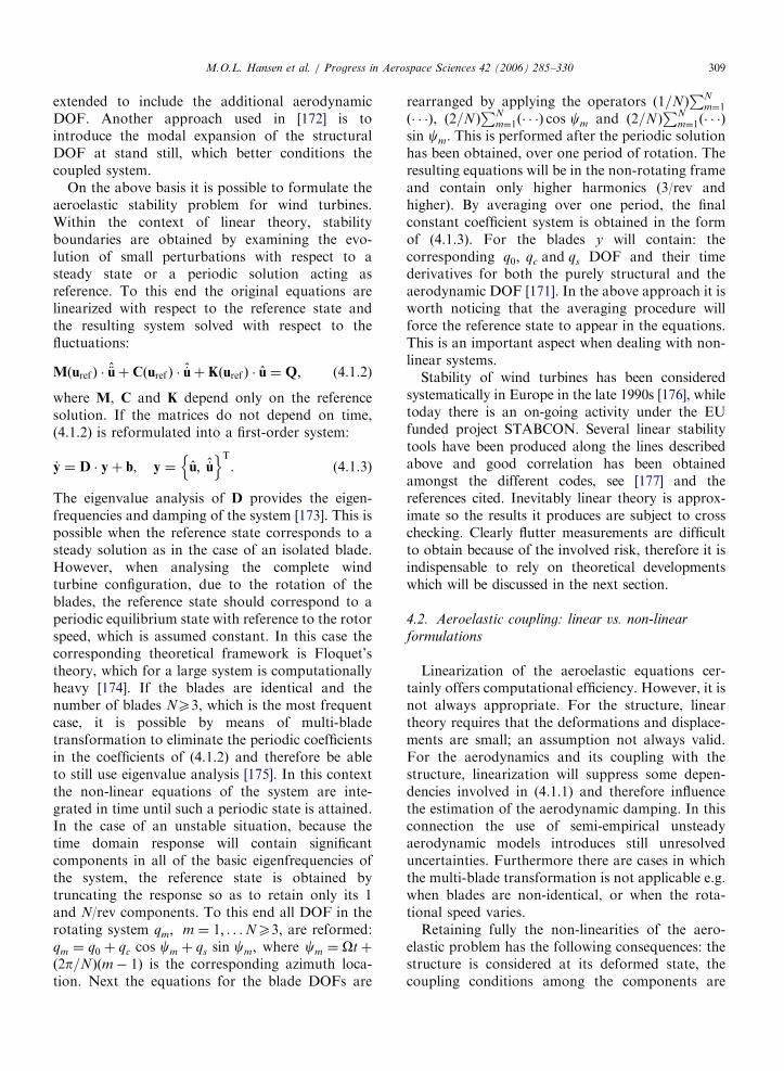
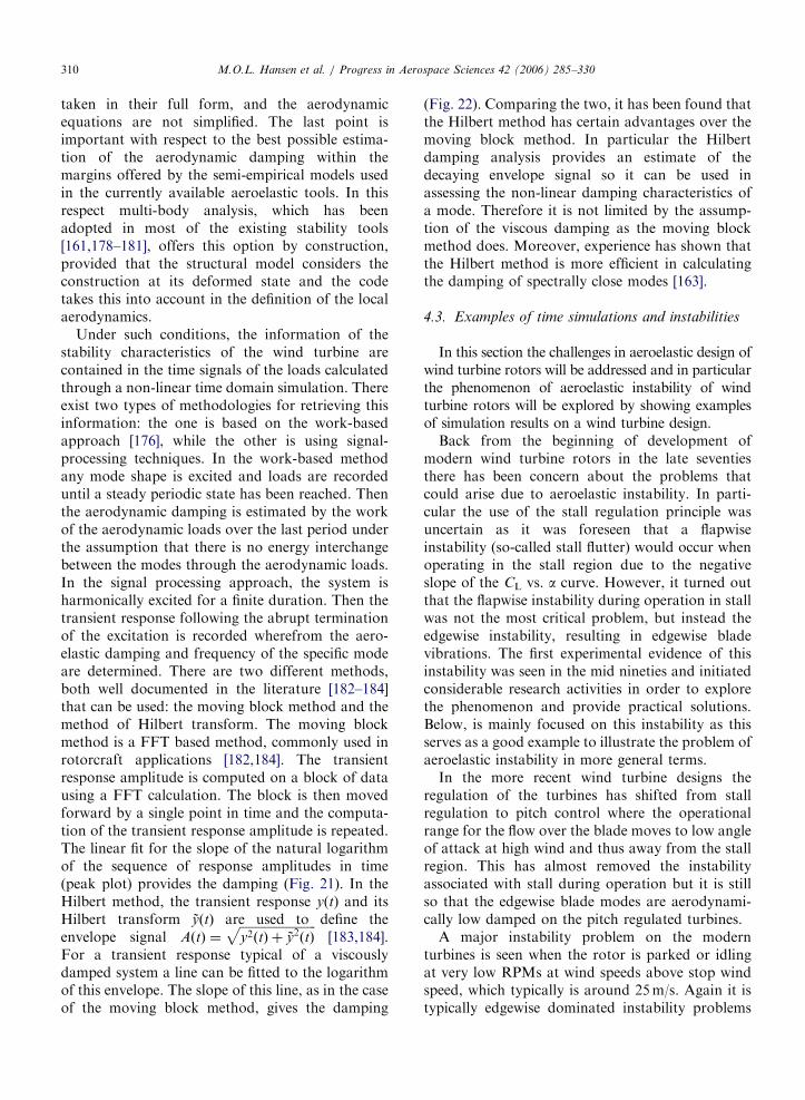
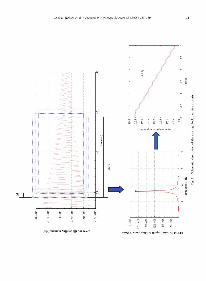
ARTICLE IN PRESS
-15e+06
-1e+06
-500000
0
500000
1e+06
15e+06
2 4 6 8 10 12 14
tow
er to
p til
t ben
ding
mom
ent (
KN
m)
time (s)
transient signalenvelope signal
envelope signal exp fit
Fig 22 Envelope signal calculation of the tower top tilting moment transient response using the Hilbert transform method for the same
signal as in Fig 21
1000
800
600
400
200
0
-2000 50 100 150 200 250 300
Time [sec] Time [sec]
ED
GE
WIS
E B
LA
DE
RO
OT
MO
ME
NT
[U
NC
AL
IBR
AT
ED
]
ED
GE
WIS
E B
LA
DE
RO
OT
MO
ME
NT
[U
NC
AL
IBR
AT
ED
]
EDGEWISE BLADE VIBRATION INSTABILITY EDGEWISE BLADE VIBRATION INSTABILITY--MEASUREMENT
1000900800700600500400300200100
0-100
200 210 220 230 240 250 260
Fig 23 Measured edgewise blade root moment on a stall regulated rotor at high wind Detail of the time track to the right
MOL Hansen et al Progress in Aerospace Sciences 42 (2006) 285ndash330312
related to stall of the blade A simulation examplewill be shown later to illustrate this problem
Finally the flutter instability will be addressed Itseems that the increased up scaling of the turbineshas led to rotor and blade designs where the flutterspeed is not so far away from normal operationalspeed Also this instability will shortly be illustrated
431 Edgewise blade vibration instability
As mentioned above the first experimentalevidence of this instability was seen in the mid
nineties on stall-regulated rotors with a diameter of35ndash40m An example is presented in Fig 23 and it isseen that the amplitude of the edgewise blade rootmoment (which at steady conditions vary sinusoidalwith 1p due to the gravity) increases 2ndash3 times dueto instability during operation in stall The experi-mental evidence of the edgewise instability led toconsiderable research on this subject and a majorEuropean project lsquolsquoPrediction of Dynamic Loadsand Induced Vibrations in Stallrsquorsquo funded by the EUwas carried out in the period from 1995ndash1998 [176]
ARTICLE IN PRESSMOL Hansen et al Progress in Aerospace Sciences 42 (2006) 285ndash330 313
The origin of the instability is simple If a rotatingairfoil section is harmonically translated along anaxis xB and the direction of this axis yRB relative tothe orientation xR of the rotor plane is varied theaerodynamic damping coefficient for the sectionvaries considerably see Fig 24 from [185] For lowyRB which means in-plane or edgewise vibrationdirection the damping coefficient is negative even atlow wind speed For vibrational directions close to901 which corresponds to out-of-plane or flapwisedirection the damping coefficient is strongly depen-dent on the inflow wind speed It is highly damped
Fig 24 The aerodynamic damping coefficient c_xx_b for a rotating a
different inflow velocities from [185]
Fig 25 Damping characteristics computed for a rotating isolated bl
at low wind but close to zero or negative damped athigh wind
On a complete rotating blade the direction ofvibration depends on the structural design of theblade as well as of the complete turbine structureThe movement of the tip section of the blade willnow no longer necessarily be along a straight lineHowever typically the tip section of the blade in thefirst flapwise mode will be on a path almostperpendicular to the rotor plane and in the 1stedgewise mode it will almost be in-plane It is thusexpected that the basic damping characteristics of
irfoil section as function of vibration direction yRB and at three
ade using the linear aeroelastic stability tool HAWCStab [186]
ARTICLE IN PRESSMOL Hansen et al Progress in Aerospace Sciences 42 (2006) 285ndash330314
the whole blade will be comparable with thecharacteristics of a single airfoil section Using thelinear stability tool HAWCStab the dampingcharacteristics for a rotating blade can easily bederived and the computed damping characteristicsfor a rotating 19m blade (500 kW rotor) corre-sponding to the blades of the rotor where theexperimental instability was shown in Fig 23 areshown in Fig 25 from [186] It is seen that thedamping for the first flapwise mode varies fromhighly positive values at low wind speed and tovalues close to zero at 14ms and then increasingslightly at higher wind speeds It should be notedthat the influence of using unsteady blade sectionaerodynamics is shown (modelled with the BeddoesLeishman model in the present case) and that thishas considerable influence on the aeroelastic damp-ing Generally the unsteady aerodynamic effectsincrease the damping The damping for the firstedgewise mode is seen to decrease gradually withincreasing wind from being slightly positive at lowwind to slightly negative at high wind Finally itshould also be noted that the damping shown is thetotal damping including the structural dampingwhich in the present case is around 2 for the firstflapwise mode and 3 for the first edgewise mode
The final step in model complexity is nowobtained by going to a full aeroelastic model ofthe turbine comprising the dynamics of the shaftthe nacelle and the tower The aeroelastic stability
Fig 26 Aeroelastic damping computed with the aeroelastic stability HA
speed
results using HAWCStab is for the complete windturbine see eg Fig 26 from [186] showing theaeroelastic damping for the first 10 mode shapes(numbered from lowest frequency) It is seen thattwo mode shapes are negatively damped at highwind speed and that one mode shape is close to zeroand slightly negatively damped at the highest windspeed For comparison time simulations with theaeroelastic code HAWC [187188] is performed onexactly the same turbine model at a wind speed of 8and 16ms respectively in order to see if theinstability at high wind speed predicted by the linearstability tool can be confirmed by the HAWCmodel with non-linear aerodynamics The com-puted edgewise blade root moment shown in Fig 27confirm the instability at high wind and comparesvery well with the measured instability shown inFig 23 It is thus demonstrated that the edgewiseinstability problem can be predicted in both timesimulations and using linearized stability analysisHowever as will be demonstrated below theedgewise vibration instability is much more complexthan just edgewise vibrations of the individualblades but comprises the dynamic characteristicsof the whole turbine This understanding is vital forthe development of design solutions preventing theinstabilities
In order to analyse the instability in more detailsthe use of parallel aeroelastic time simulations on aturbine with a stiff structure is made In this case the
WCStab [186] Three modes have negative damping at high wind
ARTICLE IN PRESSMOL Hansen et al Progress in Aerospace Sciences 42 (2006) 285ndash330 315
loads on the different components will mainlyreflect the direct load input from the externalaerodynamic forces and from gravity forces Itshould be mentioned that the simulations areperformed at two average wind speeds of 8 and16ms respectively and with a turbulence intensityof 12
A power spectral density analysis of the simulatededgewise blade root moment shows a distinct peakat 307Hz which is close to the frequency of the firstedgewise mode for a single rotating blade which is319Hz see Fig 28 The response at 16ms of theflexible turbine at this frequency is seen to be severalorders of magnitude bigger than the response of thestiff turbine indicating an instability situationSomewhat the same tendency is seen at 8ms but
Fig 28 Comparison of power spectra of edgewise blade root momen
Fig 27 Time simulation with the aeroelastic code HAWC on a 50
with considerable less difference between the re-sponse of the stiff and flexible turbine indicating lowdamping but not an instability
Analysing further the results of the stabilityanalysis with HAWCStab as shown in Fig 26 itcan be derived from the results of the model that thethree mode shapes that are negatively damped orvery low damped at 16ms are
t fo
0 k
mode no 1 with frequency 077Hz and damping605
mode no 3 with frequency 093Hz and damping433
mode no 7 with frequency 273Hz and damping
159
r a flexible and a stiff turbine respectively at 8 and 16ms
W stall regulated rotor at two wind speeds 8 and 16ms
ARTICLE IN PRESSMOL Hansen et al Progress in Aerospace Sciences 42 (2006) 285ndash330316
The numbering in HAWCStab of the modes iswith increasing mode number with increasingfrequency starting with the lowest frequency Modeno 1 and no 3 are both modes where lateral towerbending is the main motion together with edgewisebending of the three blades and torsion of the mainaxis The edgewise movement of the blades are all inphase and the difference between the two modes isthe direction of the edgewise bending relative to thetower bending Comparing again the results of thelinear stability analysis with the time simulationresults the instability of the lateral tower bendingdominated modes is confirmed by the spectra of thetower top and tower bottom lateral bendingmoments Figs 29 and 30 A distinct peak at
Fig 29 Comparison of power spectra of tower top lateral moment
Fig 30 Comparison of power spectra of tower bottom lateral mome
079Hz is seen in both tower top and tower bottomspectra at 16ms and this peak cover probably alsoa considerable content at the 093Hz which was thefrequency of mode no 3
It can be noticed that the HAWCStab results donot contain an unstable mode with a frequencyaround 307Hz (the edgewise instability) as seen inthe time simulation results However mode no 7 isin fact the response on the non-rotating turbinestructure from the edgewise vibrations at 307HzThe edgewise vibrations in the present case is a so-called backward whirling edgewise mode wherethere is a phase shift of 1201 between the movementof the blades This whirling mode results in shaftand tower bending but with a frequency shifted 1p
for a flexible and a stiff turbine respectively at 8 and 16ms
nt for a flexible and a stiff turbine respectively at 8 and 16ms
ARTICLE IN PRESSMOL Hansen et al Progress in Aerospace Sciences 42 (2006) 285ndash330 317
(p is the rotational frequency) up and downrespectively compared with the frequency in therotating system As 1p in the present case is 045Hza peak in the spectra of tower bending at afrequency of around 307ndash045Hz equal to 262Hzis expected which is also seen in Figs 28 and 29However in the HAWCStab results a slightlyhigher frequency 273Hz was seen for this mode
The presented example of the edgewise bladevibration instability has shown that the low aero-dynamic damping of an airfoil section undergoing amotion along a path close to the chordwise directioncan cause instability of quite different modes on theturbine at the same time The design challenges withthe objective to minimize the influence of lowaerodynamic damping or instability are thus big aseg changes in tower design could lead to egedgewise vibrations on the rotor A number ofdifferent methods to reduce the risk for edgewisevibrations on stall-regulated turbines have beeninvestigated [176186] and comprises eg changes ofthe stalling characteristics of the airfoils by so-calledlsquolsquostall stripsrsquorsquo as well as structural design of theblades to achieve optimal vibrational directions
432 Instability problems of parked rotors
The turbines are normally designed to operate upto a certain maximum wind speed and above thiswind speed the turbines are shut down In thestopped conditions the rotors can be completelyparked or they can idle with low rotational speeddepending on the actual design of the controlsystem As part of the certification of the turbineit must be shown that the turbine can withstand the
Fig 31 Simulation of a parked rotor at 50ms and a yaw error of 601
power spectrum of the same signal to the right
wind loads at extreme wind speed conditions withparked rotor and the wind coming from anydirection in the case that the yawing system of theturbine is not functioning
As an example the simulation of a rotor parkedat a wind speed of 50ms and a yaw error of 601 isshown in Fig 31 The turbine is the same as aboveand the time track of the edgewise blade rootmoment indicates low damping as the amplitudesvary much in time To the right in Fig 31 is shown apower spectrum of the same signal and it shows thatthe blade mainly vibrates in two modes mode 3 at afrequency of 093Hz which was described aboveand the first edgewise blade frequency at about319Hz For the present inflow direction thevibrations are not unstable but it has to bedocumented for all inflow directions
433 Flutter instability
The last example of an instability is flutter This isa well-known instability from the aircraft industrybut has not yet been a problem on wind turbinesand has probably not been seen on commercialturbines However with the increasing size of theblades it seems that the flutter speed decreases dueto increasing structural flexibility of the blades andnot least the torsional frequency decreases There-fore it is a good idea to include a flutter speedcalculation in the design verification for eg 50mblades and above
Flutter involves two DOF of the blade torsionand translation The flutter speed decreases whenthe frequency of these two DOF approach eachother For 50m blades the frequency of the first
Time track of the edgewise blade root moment to the left and a
ARTICLE IN PRESSMOL Hansen et al Progress in Aerospace Sciences 42 (2006) 285ndash330318
flapwise mode is typically slightly below 1Hz andthe frequency of the first torsional mode willtypically be in the range from 5 to 8Hz Howeverit has been seen that the flutter instability can occurby a coupling of the second flapwise mode and thefirst torsional mode of the blade and of course this isalso a reason for a decreasing flutter speed on thebigger blades Another important design parameterfor the flutter instability is the centre of mass in theblade sections relative to the centre of the elasticaxis As the centre of mass moves away from theelastic axis in the direction of the trailing edge theflutter speed decreases
An example of a simulated flutter instability isshown in Fig 32 The blade does not represent anindustrial blade but has selected structural para-meters which give a rather low flutter speed Thesecond flapwise mode for the blade is slightly above2Hz and the first torsional frequency is around6Hz Further the centre of mass is positioned 10of the chord length behind the elastic axis Theexample is mainly intended to show the character-istics of the flutter instability which is completelydifferent from the instabilities that have been seenso far In the simulation the rotor is free to speed upas the generator is disconnected When the flutterspeed is reached the instability develops within 1ndash2 sand this is completely different from eg theedgewise blade instability that can build up over aminute or more This characteristic means the bladeprobably will be damaged immediately if the flutterspeed is reached A further consequence of this fastdevelopment is that the flutter can occur at a lowerrotational speed of the rotor if there is a yaw errorThis is demonstrated in the right part of Fig 31
Fig 32 Example of flutter instability on a 50m test blade where the r
right there is a yaw error of 501
where there is a yaw error of 501 Here therotational speed at flutter instability is 13 lowerthan if there is no yaw error and the wind speed isjust 8ms If the for example the yaw error of 501occurred at around the stop wind speed of 25msthe rotational speed at the flutter instability woulddecrease even further
5 Present and future developments of aeroelastic
models
The improvement of existing aeroelastic codesand the development of new aeroelastic models arehighly influenced by the design trends of new windturbines and trends in the siting of the turbinesbecause this determines the needs for new capabil-ities of the models
51 Areas with influence on the development of
aeroelastic models
511 Influence of up-scaling
So far the most important design trend has beenthe up-scaling which within the last 10 years hasincreased the maximum size of the mass producedturbines with a factor of 10 from about 500 kW witha rotor diameter of about 40m to 5MW turbineswith a rotor diameter of 120m The newest turbinesare all pitch controlled with variable speed andtypically with some type of cyclic pitch for loadalleviation An accurate modelling of these newflexible turbines has increased the requirements tosimulate complex coupled modes where the inte-grated flexibility of the tower of the drive train andof the blades and in interaction with the control is
otor is free to speed up To the left normal inflow whereas to the
ARTICLE IN PRESSMOL Hansen et al Progress in Aerospace Sciences 42 (2006) 285ndash330 319
important Also non-linear effects from consider-able deflections of the blades and the tower arebecoming important and the aeroelastic stabilitymust be predicted with a good accuracy Sometypical frequencies for a 5MW turbine could be
First tower bending frequency
02ndash025Hz
First flapwise frequency
08ndash10Hz
First edgewise frequency
09ndash11Hz
First blade torsional frequency
50ndash70Hz
The decrease in the fundamental turbine frequen-cies arising from the up-scaling has the effect thatexcitation from the turbulent inflow has increased asthe power spectrum of the turbulence peaks ataround 005Hz
512 Siting of the turbines
The major part of all new turbines is placed insmall or bigger groups and in some cases in windfarms with more than 100 turbines This means thatwake operation is part of the inflow conditionswhich has to be simulated in the derivation of thetotal design loads of the turbines Load alleviationby cyclic or individual pitch controls is importantfor such inflow conditions and the aeroelasticmodels should be suited for this
Still the major part of turbines are set up on landbut the offshore part will increase at least if a 5ndash10years interval is considered On land the best siteshave been used in many countries and thereforemore and more complex sites will be used Thismeans that rather complex inflow situations must bemodelled as for example complex shear and non-uniform turbulence over the rotor disc
513 Future trends in turbine design and siting
It seems that the speed of up-scaling might beslowed down for some years as the industry wantsto be more focused on turbine reliability One wayto improve this is to have the individual turbinemodels on the market for more years than seen inthe past
However the increasing offshore developmentwill support the up-scaling tendency as the tran-sport and erection of big turbine components is nolonger a major problem Further the higherfoundation costs offshore will also support the up-scaling trend
Extending the possible offshore sites to deeperwater new foundation types typical with multipleframes will be developed and the aeroelastic codes
should be able to handle these structures A furtherstep in the offshore development is the floatingturbines either as single floating turbines or moreturbines on the same floating frame
Finally the offshore market could have the effectthat the two bladed turbine with a teetered down-wind rotor again will be considered as an alternativeto the three-bladed machines The main barrier forthe development of two bladed turbines has beenthe low frequency noise from the blade passage ofthe tower shadow This will be of less importanceoffshore as the noise restrictions are much lowerhere
52 Areas of development in present and new codes
Influenced by the continuously increasing require-ments to the capabilities of the aeroelastic models asdescribed above existing models are being furtherdeveloped and improved and new codes are writtenBelow some important areas of development will bediscussed
non-linear structural dynamics
calculation of induction and its dynamics
wake operation
derivation of airfoil data for aeroelastic simula-
tions
complex inflow
aerodynamics of parked rotors and
off shore turbines including floating turbines
521 Non-linear structural dynamics
So far almost all aeroelastic codes have containedthe model assumptions of small deformations androtations but the increased flexibility of the turbineshave made uncertainty about the validity of thisassumption for the new designs The influence ofnon-linear effects on the dynamic response of aturbine was treated in a recent paper [189] anddifferent effects were considered For examplecharacteristics (frequency and damping) of the firstedgewise mode will typically change as function ofincreased flapwise deflection because the edgewisebending will couple more and more with thetorsional mode of the blade Besides increasedinfluence to non-linear effects from the flexibilityof the turbine components the new foundationsused offshore and in particular floating foundationscan contribute significantly to big deflections andrelated non-linear effects
ARTICLE IN PRESSMOL Hansen et al Progress in Aerospace Sciences 42 (2006) 285ndash330320
To overcome this uncertainty about the impor-tance of non-linear effects a few new non-linearaeroelastic codes have now been developed Siemenswind power has developed a non-linear codeBHawC based on co-rotaing elements [190] whilethe new non-linear code HAWC2 [191] developedby Risoe is based on multibody dynamics
The trend of including non-linear effects willcontinue in the future and codes based on modalexpansion techniques will be developed to includemore modes as eg the blade torsional mode
522 Calculation of induction and its dynamics
The unsteady aerodynamic air loads are directlydependent on the computed induction at the samepoint on the blade through the angle of attackTherefore an accurate prediction of induction is ofcrucial importance
As the rotor disc has become bigger and biggerrelative to the scales in the turbulent inflowincreasing variation in inflow conditions over therotor disc are seen Wind shear contributes to thisvariation in inflow The inflow variations results inlikewise considerable variation in the loadingexpressed through the local thrust coefficient CTlocal
over the rotor disc and thus also in induction Theinduction is therefore even in normal operationhighly dynamic and the induction model should beadapted to these conditions As an example Fig 33
Fig 33 Example of dynamic loading at a point close to the tip of a b
(reproduced from [192]) shows the variation of thelocal thrust coefficient at the outer part of the bladeon an 80m diameter turbine in normal operation
Another source contributing to the load varia-tions and thus to the dynamic induction is theeigenmotion of the blades This part is alsoincreasing due to up-scaling and due to the moreflexible designs As an example a blade with aflapwise frequency of 1Hz as mentioned above andvibrating with an amplitude of 1m will experience arelative velocity component perpendicular to thechord of around 76ms in maximum This valuecan directly be compared with the variations ininflow and is thus considerable Different develop-ments to improve the computation of inductionhave been seen One type of modelling is thecoupling of a numerical actuator disc model to thestructural part of the aeroelastic model So far suchmodels have mainly been used to verify the accuracyof BEM modelling As an example the aeroelasticcode HAWC at Risoe with a BEM-type inductionmodelling in the standard version has been devel-oped in another version HAWC-3D where theinduction is computed with a 3D actuator discmodel and used eg to investigate the accuracy ofyaw modelling [142193] see Fig 34 from [142] Inthe coming years aeroelastic codes coupled to anactuator disc or actuator line model for computa-tion of induction will certainly be further developed
lade on an 80m diameter turbine in turbulent wind from [192]
ARTICLE IN PRESS
Fig 34 Influence of yaw on the local inflow angle The curves show the difference in local inflow angle at yawed operation at 451
compared with non-yawed operation The HAWC model has a BEM induction model HAWC-3D a 3D actuator disc model and
EllipSys3D is a full 3D NavierndashStokes simulation from [142]
MOL Hansen et al Progress in Aerospace Sciences 42 (2006) 285ndash330 321
but probably mainly used for research and forverification of simpler codes and not so much in theaeroelastic codes used by the industry due to themuch longer simulation time
However besides a direct coupling of an actuatordisc or line method to an aeroelastic code in order tocompute the induction at each time step there areother ways to utilize the capabilities of an actuatordisc model One example is to compute theinduction characteristics of a rotor within its windspeed operational interval with an actuator disc andthen afterwards use these quasi-steady inductioncharacteristics in aeroelastic simulations for therotor The BEM method in the new HAWC2aeroelastic code developed at Risoe has beenimplemented in such a way that this method canbe used The method is shortly first to compute thelocal induction as function of local loading for theactual rotor in a number of calculation points ethn mTHORN over the rotor with an actuator disc
aethrn ymTHORN frac14 f CT rn ymeth THORNeth THORN
Afterwards these induction functions are then usedin the BEM method during time simulations on therotor instead of the unique single relationship from1D momentum theory CT frac14 4aeth1 aTHORN
In fact one of the main deficiencies of the BEMmethod is that this induction formula concerns thewhole rotor disc Deviations are seen in regions withconsiderable radial variation in the loading whichmeans in the tip or root region Another examplewhere the momentum induction formula does nothold is if the rotor disc is not plane eg conedrotors or rotors where the blades bend considerably
523 Wake operation
Most turbines are now set up in clusters or windfarms and this means that such turbines in part oftheir lifetime operate in wake from one or moreturbines In the international standard for design ofturbines IEC 61400-1 [2] the increased loading fromoperation in wake can be taken into account byusing an increased effective turbulence whichdepends on a number of parameters in theconsidered wind farm such as eg wind turbinespacing However it has turned out that in caseswhere more detailed knowledge of the increasedloading on the different turbine components fromwake operation is needed another more detailedaeroelastic modelling is needed than just increasingthe turbulence One such aeroelastic modelling hasbeen developed over the past few years [194195]The main components in the modelling is (1)
ARTICLE IN PRESSMOL Hansen et al Progress in Aerospace Sciences 42 (2006) 285ndash330322
computation of the wake deficit from the up-streamturbine with an actuator disc model (2) meanderingof this deficit from the big scales in the turbulenceand (3) additional turbulence within the wake Oneof the advantages of this new modelling comparedto the method using an effective turbulence is thatboth the mean yaw loads as well as the yawdynamics compare well with measurement Fig 35from [194] shows the loads as function of winddirection and full wake operation at a direction ofaround 2101 The highest mean yaw loads occur inhalf wake operation at around 1951 and 2201Recently the wake resulting from the interaction ofseveral turbines in a row was computed in [196] bycombining large eddy simulation of the NS equa-tions with the actuator line methodology
Fig 35 Measured and simulated loads at 8ms (crosses and full lines)
wake operation (full wake at around 2101 on x-axis) using a new aeroel
meandering from [194]
It is expected that the more detailed aeroelasticmodelling of wake operation will be developedconsiderably in the coming years because suchmodelling is necessary for the development ofadvanced control algorithms adapted for loadreduction in wakes The development of the newdetailed models can be in the direction like themodel described above but also using actuator linemodels or full 3D rotor models to compute the wakecharacteristics which can be fed into an aeroelasticsimulation
524 Derivation of airfoil data for aeroelastic
simulations
The airfoil data used in aerodynamic and aero-elastic simulations are of crucial importance for the
and at 10ms (squares and dashed lines) on a 80m rotor during
astic wake simulation method taking into account the wake deficit
ARTICLE IN PRESSMOL Hansen et al Progress in Aerospace Sciences 42 (2006) 285ndash330 323
accuracy of such simulations This was clearly seenin the result of the NREL blind test [137] where thedifference in the airfoil data used in the individualsimulation models probably were the most signifi-cant factor for the big variation between the outputof the different simulations However it should benoted that this result is not a representativeindicator of the uncertainty in the industry onaerodynamic and aeroelastic results on new turbinesas considerable experience has been learned fromolder rotor designs in order to adapt airfoil data setsso that computed rotor power and loads comparewell with measurements The drawback is that thisintroduces conservatism in the design and forexample can hinder the use of new airfoils There-fore methods and models to derive or correct airfoildata to be used in aeroelastic simulations have beena key issue for many years in the wind energyresearch community and will also be it in the nearfuture 2D wind tunnel airfoil data has so far beenthe common starting point to set up an airfoil dataset for simulations In order to correct for so-called3D flow effects and rotational effects some kind ofcorrection is typically applied [19ndash21197] Thecorrections reflect the increased lift and drag thatwas measured on different rotors in field rotormeasurements performed 10ndash15 years ago [198199]Full 3D CFD rotor computations later confirmedclearly the tendencies of the 3D flow effects androtational effetcts in the form of increased lift in theblade root region but also increased drag [137ndash139]
With the possibility of running full 3D simula-tions on a rotor a new source for derivation of 3Dairfoil data sets for input in aerodynamic and
2
18
16
14
12C1
1
08
06
040 5 10 15 20 25 30
r=14r=28r=42r=56r=69r=89r=94r=97
35 40α
Fig 36 Extracted 3D airfoil data in the form of CL CD data as functi
rotor computation Figure from [202]
aeroelastic codes has emerged Methods to extractthe airfoil data from 3D rotor computations havebeen developed [200201] One example of such aderived airfoil data set is shown in Fig 36 from[202] where a considerable increased maximum lifton the inboard stations are seen Within the nextfew years it is expected that a considerable effortwill be on further development of the methods toextract airfoil data from 2D wind tunnel data aswell as 3D CFD rotor data So far the CFDcomputations have mainly been used to extractquasi-steady data but they will in the future also beused to tune the parameters in the dynamic stallmodels
525 Complex inflow
Wind turbines are often set up in so-calledcomplex terrain which means some kind ofmountainous terrain because the wind potential isgood at such places However the consequence isthat the inflow conditions can vary considerablyfrom turbine to turbine due to local variations ofthe terrain As a result extreme wind shear has beenseen to occur over the rotor disc of turbines placedin such terrain and likewise the turbulence intensitycan be extremely high
The fast development of CFD codes has nowmade it possible to simulate the flow in detailsover the terrain spanned by a wind farm in suchcomplex terrain The flow data in the form of windshear and turbulence can be used as input inaeroelastic simulations There is thus a basis for asimulation tool to micro site turbines not only withrespect to energy production but also loads is
Cd
r=14r=28r=42r=56r=69r=89r=94r=97
α
05
045
04
035
03
025
02
015
01
005
00
5 10 15 20 25 30 35 40
on of angle of attack at different radial stations from a 3D CFD
ARTICLE IN PRESSMOL Hansen et al Progress in Aerospace Sciences 42 (2006) 285ndash330324
expected Thus type of modelling is certainly ofhigh interest for the wind turbine industrybecause considerable costs to repair turbines dueto extreme inflow conditions have been experiencedin the past
526 Aerodynamics of parked rotors
It is a common procedure to shut the turbinesdown at high wind typically at wind speeds in therange from 20 to 25ms Ultimate loads on parts ofthe wind turbine can occur during standstill condi-tions at very high wind speed whereas ultimate loadson other components will occur during operationbelow the stop wind speed
The aerolelastic codes are therefore also used tocompute the turbine response during standstillconditions and it is particularly the computationof the aerodynamic loads on the blades that isuncertain This is due to the requirement that theloads on the parked rotor shall be investigated withthe wind from all directions The models musttherefore be able to compute aerodynamic loads forangle of attacks in the complete range from ndash180o to180o Furthermore the inflow is turbulent so that itis highly unsteady aerodynamic loads and a severecomplication is that some inflow conditions oftenlead to instability with the blade vibrating in a modewith negative aerodynamic damping In a recent EUfunded project lsquolsquoKNOWBLADErsquorsquo different CFDcodes were used to explore some basic character-istics of the blade standstill aerodynamics [115]Because of the complexity of the aerodynamics it isalso believed that the use of CFD will be the mainpath to explore the standstill aerodynamics in thecoming years
Fig 37 Different support struc
527 Offshore turbines including floating turbines
Presently there are considerable research anddevelopment efforts on adapting aeroelastic modelsto simulate offshore wind turbines mounted on asub-structure standing on the sea-bed see Fig 37from [203] or on a floating foundation
Different approaches are seen in this develop-ment One line is characterized by a completeintegration of the standard aeroelastic model ofthe turbine with a hydroelastic model of the sub-merged supporting structure including the hydro-dynamic loads the wave loading and the soil forceson the part of the support structure in the sea bed[190191] In both these models the completestructure is described with finite elements and withengineering sub-models for computation of thehydrodynamic loads
Another line of modelling is to couple alsquolsquostandardrsquorsquo aeroelastic model to a separate modulesimulating the supporting structure including waveloads and hydro loads This approach has beenpresented by Repower [204] where the Flex5aeroelatic code is coupled with a standard packageASAS for computations of wave loads on off shorestructures In the third development line the mainidea is also to use a lsquolsquostandardrsquorsquo aeroelastic code andthen couple it to a super element of the foundationThis approach has been presented by Vestas [203]where the foundation is modelled with a finiteelement model but then decomposed to a superelement using the CraigndashBampton sub-structuringscheme Considerable efforts on further develop-ments of the aeroelastic models for off shoreapplications will be seen within the next years andwith more emphasis on deeper water installations
ture concepts from [203]
ARTICLE IN PRESSMOL Hansen et al Progress in Aerospace Sciences 42 (2006) 285ndash330 325
6 Discussion
On a wind turbine there is a strong couplingbetween the aerodynamic loads and the time-dependent structural behaviour of the constructionStatically a blade might change its twist and thus theangle of attack when deflected But also the anglesof attack are changed when the blades have avelocity relative to the fixed ground For instance ifthe tower is moving upstream and everything else isstiff it will be felt by the blades as an increased windspeed and thus higher angles of attack will bepresent along the blades The aerodynamic responsewill depend on how the lift and drag vary with theangle of attack In stall the lift will decrease yieldinga possible instability whereas for attached flow thelift will increase and thus creating a higher load seenby the blade opposite the movement indicatingstability On a real wind turbine not only the toweris vibrating but all other components as well whichdirectly feeds back to the angle of attacks and thusthe loads that again alter the motion To simulatethe aeroelastic response of a wind turbine a non-steady structural model including the inertia mustbe made Two methods ie the method of virtualwork applied on modal shape functions and theFEM are addressed To evaluate the aerodynamicloads the BEM is still the most widely used due toits simplicity and computing efficiency To obtainrealistic results some engineering adds-on arenecessary such as the Dynamic Wake DynamicStall and a yaw model which are thereforethoroughly described in this paper A BEM methodrelies however on airfoil data and the results aretherefore no better than the input To avoid theuncertainties of the engineering adds-on the Actua-tor Line model can be used since this methodresolves the physics of these models through the NSequations However the actual blades are notresolved and to estimate the aerodynamic lift anddrag airfoil data are still needed To avoid airfoildata one needs to solve the NS equations andresolve the blades and the possible boundary layersThis is extremely computationally costly and there-fore this model is not likely to replace the BEMmethod in the near future However the methodcan be used to extract airfoil data that can be usedin the less advanced models It is expected that theActuator Line model very soon will replace theBEM method since it contains less empirics Withthe AL model the wake is also a part of the solutionand therefore the effect from this wake on a wind
turbine placed further downstream can be calcu-lated These simulations are becoming very impor-tant as wind turbines are grouped in large (offshore)wind parks The inviscid flow models are included inthis paper mainly for historical reasons since theyhave played an important role in determining basicphysical features This type of model was eg usedto calibrate the time constants in the DynamicWake model Also a few Potential flow models existthat model the induced velocities and the wakebehind a wind turbine by shedding vortex blobsfrom the blade surface This model is similar to theAL model and may also in some aeroelastic codesreplace the BEM method
References
[1] Last og sikkerhed for vindmollekonstruktioner DANSK
STANDARD DS 472 [in Danish]
[2] IEC 61400-1 Ed3 CD 2 revision Wind turbines Part 1
design requirements Edited by IEC TC88-MT1 25ndash26
May 2004
[3] Hansen KS Performance Measurements on two Danish
630 kW WECS In Proceedings of the WIND POWERrsquo85
SERICP-217-2902 1985 p 130ndash5
[4] Hansen KS et al An evaluation of measured and predicted
fatigue loads for the Tjaeligreborg wind turbine In Proceed-
ings of ECWECrsquo93 Travemunde Germany 1993
p 579ndash82
[5] Ahlstrom A Aeroelastic simulation of wind turbine
dynamics Doctoral thesis in Structural Mechanics KTH
Sweden 2005
[6] Glauert H Airplane propellers In Durand WF editor
Aerodynamic theory New York Dover Publications 1963
[7] Rasmussen F Hansen MH Thomsen K Larsen TJ
Bertagnolio F Johansen J et al Present status of
aeroelasticity of wind turbines Wind Energy 20036213ndash28
[8] Quarton DC The evolution of wind turbine design
analysismdasha twenty year progress review Wind Energy
199815ndash24
[9] Hansen AC Butterfield CP Aerodynamics of horizontal-
axis wind turbines Annu Rev Fluid Mech 199325115ndash49
[10] Shen WZ et al Tip loss corrections for wind turbine
computations Wind Energy 20058(4)457ndash75
[11] Snel H Schepers JG Joint Investigation of dynamic inflow
effects and implementation of an engineering method
ECN-Cndash94-107 1995
[12] Schepers JG Snel H Dynamic inflow yawed conditions
and partial span pitch control ECN-C-95-056 1995
[13] Bramwell ARS Helicopter dynamics Paris Edward
Arnold (Publishers) Ltd 1976
[14] Theodorsen T General theory of aerodynamic instability
and the mechanism of flutter NACA report 496 1935
p 413ndash33
[15] Oslashye S Dynamic stall simulated as a time lag of separation
In KF McAnulty editor Proceedings of the fourth IEA
symposium on the aerodynamics of wind turbines ETSU-
N-118 1991
ARTICLE IN PRESSMOL Hansen et al Progress in Aerospace Sciences 42 (2006) 285ndash330326
[16] Leishman JG Beddoes TS A semi-empirical model for
dynamic stall J Am Helicopter Soc 198934(3)3ndash17
[17] Hansen MH Gaunaa M Madsen HA A BeddoesndashLeish-
man type dynamic stall model in state-space and indicial
formulations Risoe-R-1354(EN) 2004
[18] Johansen J Soslashrensen NN Aerofoil characteristics from 3D
CFD rotor computations Wind Energy 20047(4)283ndash94
[19] Snel H Houwink B Bosschers J Piers WJ van Bussel
GJW Bruining A Sectional prediction of 3-D effects for
stalled flow on rotating blades and comparison with
measurements In Proceedings of the ECWEC 1993
Travemunde 1993 p 395ndash9
[20] Chaviaropoulos PK Hansen MOL Investigating three-
dimensional and rotational effects on wind turbine blades
by means of a quasi-3D NavierndashStokes solver J Fluids Eng
2000122330ndash6
[21] Bak C Johansen J Three-dimensional corrections of airfoil
characteristics for wind turbines based on pressure dis-
tributions In Proceedings of the EWEC conference
Athens 27 Februaryndash2 March 2006
[22] Fuglsang P Bak C Status of the Risoe wind turbine
airfoils In Proceedings of the EWEC 2003 (CD-ROM
available from EWEA) Madrid 2003
[23] Shinozuka M Jan C-M Digital simulation of random
process and its applications J Sound Vib 197225111ndash28
[24] Veers P Three-dimensional wind simulation SAND88-
0152 UC261 Sandia National Laboratories NM 1988
[25] Mann J Wind field simulation Probl Eng Mech
199813269ndash82
[26] Soslashrensen JN Three-level viscous-inviscid interaction tech-
nique for the prediction of separated flow past rotating
wing PhD thesis AFM-83-03 Technical University of
Denmark 1986
[27] Karagiannis F Simandirakis G Chaviaropoulos P Papai-
liou KD A 3D shear layer prediction method for steady
viscous flows around HAWTs In Proceedings of the
ECWEC 1993 Lubeck-Travemunde Germany p 391ndash4
[28] Milne-Thomson LM Theoretical aerodynamics New
York Dover Publications 1966
[29] Richardson SM Cornish ARH Solution of three dimen-
sional incompressible flow problems J Fluid Mech
197782309ndash19
[30] Joukowski NE Vortex theory of a rowing screw Trudy
Otdeleniya Fizicheskikh Nauk Obshchestva Lubitelei
Estestvoznaniya 1912161
[31] Margoulis W Propeller theory of Professor Joukowski and
his pupils NACA Technical Memorandum No 79 1922
[32] Miller RH The aerodynamic and dynamic analysis of
horizontal axis wind turbines J Wind Eng Ind Aerodyn
198315329ndash40
[33] Oslashye S A simple vortex model In Proceedings of the third
IEA symposium on the aerodynamics of wind turbines
ETSU Harwell 1990 p 41ndash515
[34] Koh SG Wood DH Formulation of a vortex wake model
for horizontal-axis wind turbines Wind Eng 199115(4)
196ndash210
[35] Wood DH On wake modelling at high tip speed ratios
Wind Eng 199216(5)291ndash303
[36] Hess JL Review of integral equation techniques for solving
potential flow problems with emphasis on the surface
source method Comput Methods Appl Mech Eng 19755
145ndash96
[37] Katz J Plotkin A Low-speed aerodynamics New York
McGraw-Hill 1991
[38] Prandtl L Tietjens OG Applied hydro-and aeromechanics
New York Dover 1934
[39] Landhal MT Stark VJE Numerical lifting surface
theorymdashproblems and progress AIAA J 19776(11)
2049ndash60
[40] Kerwin JE Lee CS Prediction of steady and unsteady
marine propeller performance by numerical lifting surface
theory Trans SNAME 1978 86
[41] Hess JL Calculation of potential flow about arbitrary
three-dimensional lifting bodies McDonnell Douglas
report MDC J5679-01 1972
[42] Rehbach C Calcul drsquoecoulements autour drsquoailes sans
epaisseur avec nappes tourbillonnaires evolutives Re-
cherche Aerospatiale 1973253ndash61
[43] Cottet G-H Koumoutsakos PD Vortex methods theory
and practice Cambridge Cambridge University Press
2000
[44] Bagai A Leishman JG Rotor free-wake modelling using a
pseudoimplicit relaxation algorithm J Aircraft 199532(6)
1276ndash85
[45] Bhagwat M Leishman JG Accuracy of straight-line
segmentation applied to curvilinear vortex filaments J
Am Helicopter Soc 200146(2)166ndash9
[46] Gould J Fiddes SP Computational methods for the
performance prediction of HAWTs In Hulle FV
Smulders P Dragt J editors Wind energy technology
and implementation Amsterdam Elsevier Science Publish-
ers 1991 p 29ndash33 [EWEC091]
[47] Robison DJ Coton FN Galbraith RAM Vezza M
Application of a prescribed wake aerodynamic prediction
scheme to horizontal axis wind turbine in axial flow Wind
Eng 199519(1)41ndash51
[48] Coton FN Wang T The prediction of horizontal axis wind
turbine performance in yawed flow using an unsteady
prescribed wake model Proc Inst Mech Eng Part AmdashJ
Power Energy 199921333ndash43
[49] Afjeh AA Keith TG A simplified free wake method for
horizontal axis wind turbine performance prediction Trans
ASME J Fluid Eng 1986108303ndash9
[50] Simoes FJ Graham JMR Prediction of loading on a
horizontal axis wind turbine using a free vortex wake
model In Proceedings of the BWEA conference 1991
[51] Voutsinas SG Beleiss MA Rados KG Investigation of the
yawed operation of wind turbines by means of a vortex
particle method In AGARD conference proceedings vol
552 1995 p 111ndash11
[52] Coton FN Wang T Galbraith RAM An examination of
key aerodynamic modelling issues raised by the NREL
blind comparison Wind Energy 20025199ndash212
[53] Voutsinas SG Vortex methods in aeronautics how
to make things work Int J Comput Fluid Dynamics
2006
[54] Preuss RD Suciu EO Morino L Unsteady potential
aerodynamics of rotors with applications to horizontal axis
windmills AIAA J 198018(4)385ndash93
[55] Arsuffi G A general formulation for aerodynamic analysis
of wind turbine In Proceedings of the second IEA
symposium on the aerodynamics of wind turbines Depart-
ment of Fluid Mechanics Technical University of Den-
mark 1988
ARTICLE IN PRESSMOL Hansen et al Progress in Aerospace Sciences 42 (2006) 285ndash330 327
[56] Bareiss R Wagner S A hybrid wake model for hawt In
McAnulty K editor Proceedings of the sixth IEA
symposium on the aerodynamics of wind turbines ETSU
Harwell 1993 p 71ndash10
[57] Mughal B Drela M A calculation method for the three-
dimensional boundary-layer equations in integral form
AIAA Paper 93-0786 1993 Reno NV January
[58] Riziotis VA Voutsinas SG Dynamic stall on wind turbine
rotors comparative evaluation study of different models
In Proceedings of the EWECrsquo97 1997 Dublin
[59] Chaviaropoulos PK Nikolaou IG Aggelis KA Soslashrensen
NN Johansen J Hansen MOL et al Viscous and
aeroelastic effects on wind turbine blades The VISCEL
Project Part I 3D NavierndashStokes rotor simulations Wind
Energy 20036(4)365ndash85
[60] Rankine WJM On the mechanical Principles of the Action
of Propellers Transactions of the Institution of Naval
Architects vol 6 1865
[61] Froude RE On the part played in propulsion by difference
of fluid pressure Trans R Inst Naval Arch 188930
390ndash405
[62] Wu TY Flow through a heavily loaded actuator disc
Schiffstechnik 19629134ndash8
[63] Greenberg MD Powers SR Nonlinear actuator disc theory
and flow field calculations including nonuniform loading
NASA CR 1672 NASA 1970
[64] Greenberg MD Nonlinear actuator disc theory Z Flug-
wissensch 197220(3)90ndash8
[65] Conway J Analytical solutions for the actuator disc with
variable radial distribution of load J Fluid Mech 1995
297327ndash55
[66] Conway J Exact actuator disc solution for non-uniform
heavy loading and slipstream contraction J Fluid Mech
1998365235ndash67
[67] Madsen HA The actuator cylinder flow model for vertical
axis wind turbines PhD dissertation Aalborg University
Centre 1982
[68] van Kuik GAM On the limitations of Froudersquos actuator
disc concept PhD thesis Eindhoven University of Tech-
nology Netherlands 1991
[69] Soslashrensen JN Myken A Unsteady actuator disc model for
horizontal axis wind turbines J Wind Eng Ind Aerodyn
199239139ndash49
[70] Soslashrensen JN Kock CW A model for unsteady rotor
aerodynamics J Wind Eng Ind Aerodyn 199558
259ndash75
[71] Soslashrensen JN Mikkelsen R On the validity of the blade
element momentum theory In Helm P Zervos A editors
Proceedings of the 2001 European wind energy conference
and exhibition WIP-renewable energies Munchen 2001
p 362ndash6
[72] Madsen HA A CFD analysis for the actuator disc flow
compared with momentum theory results In Pedersen B
editor Proceedings of the 10th IEA symposium on the
aerodynamics of wind turbines Department of Fluid
Mechanics The Technical University of Denmark 1996
p 109ndash24
[73] Soslashrensen JN Shen WZ Munduate X Analysis of wake
states by a full-field actuator disc model Wind Energy
1998173ndash88
[74] Madsen HA Rasmussen F The influence of energy
conversion and induction from large blade deflections In
Proceedings of the European wind energy conference
James amp James 1999 p 138ndash41
[75] Mikkelsen R Soslashrensen JN Shen WZ Modeling and
analysis of the flow field around a coned rotor Wind
Energy 20014121ndash35
[76] Fejtek I Roberts L NavierndashStokes computation of wing
rotor interaction for a tilt rotor in hover AIAA J
199230(11)2595ndash603
[77] Rajagopalan RG Mathur ST Three dimensional analysis
of a rotor in forward flight J Am Helicopter Soc
199338(3)99
[78] Masson C Smaıli A Leclerc C Aerodynamic analysis of
HAWTs operating in unsteady conditions Wind Energy
20014(1)1ndash22
[79] Masson C Ammara I Paraschivoiu I An aerodynamic
method for the analysis of isolated horizontal-axis wind
turbines Int J Rotating Mach 1997321ndash32
[80] Hansen MOL Soslashrensen NN Flay RGJ Effect of placing a
diffuser around a wind turbine Wind Energy 20004(3)
207ndash13
[81] Phillips D Schaffarczyk AP Blade-element and actuator
disc models for a shrouded wind-turbine In Thor S-E
editor Proceedings of the 15th IEA symposium on
aerodynamics of wind turbines FOI Swedish Defence
Research Agency 2001 p 95ndash105
[82] Mikkelsen R Soslashrensen JN Modelling of wind tunnel
blockage In Thor S-E editor Proceedings of the 15th IEA
symposium on aerodynamics of wind turbines FOI
Swedish Defence Research Agency 2001 p 41ndash51
[83] Mikkelsen R Soslashrensen JN Yaw analysis using a numerical
actuator disc model In Pedersen B editor Proceedings of
the 14th IEA symposium on the aerodynamics of wind
turbines Department of Fluid Mechanics Technical
University of Denmark 2000 p 53ndash9
[84] Masson C Viscous differentialactuator disc method and
its applications In Thor S-E editor Proceedings of the
15th IEA symposium on aerodynamics of wind turbines
FOI Swedish Defence Research Agency 2001 p 65ndash80
[85] Ammara I Leclerc C Masson C A viscous three-
dimensional differentialactuator disc method for aerody-
namic analysis of wind farms J Solar EnergymdashTrans
ASME 2002124(4)345ndash56
[86] Soslashrensen JN Shen WZ Numerical modelling of wind
turbine wakes J Fluids Eng 2002124(2)393ndash9
[87] Leclerc C Masson C Towards blade-tip vortex simulation
with an actuator-lifting surface model AIAA-2004-0667
2004
[88] Mikkelsen R Actuator disc methods applied to wind
turbines PhD dissertation Department of Mechanical
Engineering DTU Lyngby 2003
[89] Ivanell SSA Numerical computations of wind turbine
wakes PhD dissertation KTH Royal Institute of Tech-
nology Stokholm 2005
[90] Arieli R Tauber ME Computation of subsonic and
transonic Flow about lifting rotor blades AIAA Paper
79-1667 1979
[91] Borland C Rizzettaq D Yoshihara H Numerical solution
of three-dimensional unsteady transonic flow over swept
wings AIAA Paper 80-1369 1980
[92] Sankar NL Malone JB Tassa Y An implicit conservative
algorithm for steady and unsteady three-dimensional
potential flows AIAA Paper 81-1016 1981
ARTICLE IN PRESSMOL Hansen et al Progress in Aerospace Sciences 42 (2006) 285ndash330328
[93] Steger JL Caradonna FX Conservative implicit finite
difference algorithm for the unsteady transonic potential
equations AIAA Paper 80-1368 1980
[94] Caradonna FX Tung C Desopper A Finite difference
modeling of rotor flows including wake effects Journal of
the American Helicopter Society April 1984 p 26ndash33
[95] Sankar NL Wake BE Lekoudis SG Solution of the
unsteady Euler equations for fixed and rotor wind
configurations J Aircraft 198623(4)
[96] Jameson Baker TJ Solution of the Euler equations for
complex configurations AIAA Paper 83-1919 1983
[97] Pulliam TH Euler and thin layer NavierndashStokes codes
ARC2D ARC3D notes for computational fluid dynamics
users workshop The University of Tennessee Space
Institute March 12ndash16 1984
[98] Agarwal RK Deese JE Euler calculations for flowfield of a
helicopter rotor in hover J Aircraft 199724(4)
[99] Srinivasan GR McCroskey WJ NavierndashStokes calcula-
tions of hovering rotor flowfields J Aircraft 198825(10)
[100] Srinivasan GR Raghavan V Duque EPN Flowfield
Analysis of modern helicopter rotors in hover by Navierndash-
Stokes method International Technical Specialists meeting
Rotorcraft Acoustics and Rotor Fluid Dynamics October
15ndash17 1991 Philadelphia Pennsylvania USA
[101] Srinivasan GR Baeder JD Obayashi S McCroskey WJ
Flowfield of a lifting rotor in hover a NavierndashStokes
simulation AIAA J 199230(10)
[102] Berkman ME Sankar LN Berezin CR Torok MS
NavierndashStokesfull potentialfree-wake method for rotor
flows J Aircraft 199734(5)
[103] Hansen MOL Soslashrensen JN Michelsen JA Soslashrensen NN
A Global NavierndashStokes Rotor prediction model AIAA
97-097 1997
[104] Soslashrensen NN Hansen MOL Rotor performance predic-
tions using a NavierndashStokes method AIAA 98-0025 1998
[105] Xu G Sankar LN Computational study of horizontal axis
wind turbines AIAA 99-0042 Reno NV January 1999
[106] Duque EPN van Dam CP Hughes S NavierndashStokes
Simulations of the NREL combined experiment Phase II
rotor proceedings 1999 ASME wind energy symposium
37th AIAA Aerospace Science Meeting and Exhibit AIAA
99-0037 Reno NV January 1999
[107] Soslashrensen NN Michelsen JA Aerodynamic predictions for
the unsteady aerodynamics experiment phase-II rotor at
the National Renewable Energy Laboratory AIAA-2000-
0037 2000
[108] Soslashrensen JN VISCWIND Viscous effects on wind turbine
blades ET-AFM-9902 Department of Energy Engineer-
ing Technical University of Denmark June 1999
ISBN87-7475-218-9
[109] Chaviaropoulos PK Nikolaou IG Aggelis K Soslashrensen
NN Montgomerie B von Geyr H et al Viscous and
aeroelastic effects on wind turbine blades the Viscel
Project European wind energy conference Copenhagen
Denmark 2ndash6 July 2001
[110] Kang S Hirsch C Features of the 3D viscous flow around
wind turbine blades based on numerical solutions Eur-
opean Wind Energy Conference Copenhagen Denmark
2ndash6 July 2001
[111] Johansen J Soslashrensen NN Reck M Hansen MOL
Stuermer A Ramboer J Hirsch C Ekaterinaris J
Voutsinas S Perivolaris Y KNOW-BLADE task-33
report Rotor blade computations with 3D vortex gen-
erators Risoslash-R-1486(EN) 2005 65p
[112] Soslashrensen NN Johansen J Conway S Voutsinas S Hansen
MOL Stuermer A KNOW-BLADE task-32 report tip
shape study Risoslash-R-1495(EN) 2005 49p
[113] Politis ES Nikolaou IG Chaviaropoulos PK Bertagnolio
F Soslashrensen NN Johansen J KNOW-BLADE Task-4
report NavierndashStokes aeroelasticity Risoslash-R-1492(EN)
2005 39p
[114] Johansen J Soslashrensen NN Zahle F Kang S Nikolaou I
Politis ES et al KNOW-BLADE Task-2 report Aero-
dynamic accessories Risoslash-R-1482(EN) 2004 33p
[115] Soslashrensen NN Johansen J Conway S CFD computations of
wind turbine blade loads during standstill operation KNOW-
BLADE Task 31 report Risoslash-R-1465(EN) 2004 28p
[116] Buning P etal OVERFLOW user manual ver 16ap
[117] Meaking R Moving grid overset grid methods for complete
aircraft tiltrotor simulations AIAA Paper 93-3350 July
1993
[118] Rizzi A Eliasson P Lindblad I Hirsch C Lacor C
Haeuser J The engineering of multiblockmultigrid soft-
ware for NavierndashStokes flows on structured meshes J
Comput Fluids 199322341ndash67
[119] Kroll N Radespiel R Rossow CC Structured grid solvers
I accurate and efficient flow solvers for 3D applications on
structured meshes AGARD report 807 1995
[120] Eliasson P Edge a NavierndashStokes solver for unstructured
grids FOI-R-0298-SE 2001
[121] Chorin AJ A numerical method for solving incompressible
viscous flow problems J Comput Phys 1967212ndash26
[122] Rogers SE Kwak D Steady and unsteady solutions of the
incompressible NavierndashStokes equations AIAA J 1991
29(4)
[123] Harlow FH Welch JE Numerical calculations of time-
dependent viscous incompressible flow of fluid with free
surface Phys Fluids 196582182
[124] Chorin AJ Numerical solution of the NavierndashStokes
equations Math Comput 196822(104)745ndash62
[125] Patankar SV Spalding DB A calculation procedure for
heat mass and momentum transfer in three-dimensional
parabolic flows Int J Heat Mass Transfer 1972(15)1787
[126] Rhie CM A Numerical study of the flow past an isolated
airfoil with separation PhD thesis University of Illinois
Urbane-Champaign 1981
[127] Menter FM Zonal Two equation kndasho Turbulence models
for aerodynamic flows AIAA-paper-932906 1993
[128] Spalart PR Allmaras SR A one-equation turbulence
model for aerodynamic flows AIAA-92-0439 1992
[129] Baldwin BS Barth TJ A one-equation turbulence trans-
port model for high Reynolds number wall-bounded flows
AIAA 91-0610 1991
[130] Baldwin BS Lomax H Thin layer approximation and
algebraic model for separated turbulent flow In AIAA
16th aerospace science meeting Huntsvill Alabama 1978
[131] Travin A Shur M Strelets M Detached-eddy simulation
past a circular cylinder flow Turbulence Combust
199963293ndash313
[132] Strelets M detached eddy simulations of massively
separated flows AIAA-2001-0879 2001
[133] Xu G Sankar LN effects of transition turbulence and yaw
on the performance of horizontal axis wind turbines
AIAA-2000-0048 2000
ARTICLE IN PRESSMOL Hansen et al Progress in Aerospace Sciences 42 (2006) 285ndash330 329
[134] Michelsen JA Soslashrensen NN Current developments in
NavierndashStokes modelling of wind turbine rotor flow In
European wind energy conference Copenhagen Denmark
2ndash6 July 2001
[135] Ferziger JH Milovan P Computational methods for fluid
dynamics Berlin Heidelberg New York Springer 2002
ISBN3-540-59434-5
[136] Fingersh LJ Simms D Hand M Jager D Contrell J
Robinson M et al Wind tunnel testing of NRELrsquos
unsteady aerodynamics experiment AIAA-2001-0035 Pa-
per 39th aerospace sciences meeting amp exhibit 2001 Reno
[137] Simms D Schreck S Hand M Fingersh LJ NREL
unsteady aerodynamics experiment in the NASA-Ames
wind tunnel a comparison of predictions to measurements
NRELTP-500-29494 June 2001
[138] Soslashrensen NN Evaluation of 3D effects from 3D CFD
computations In IEA Joint action aerodynamics of wind
turbines 14th symposium Boulder December 2000
[139] Soslashrensen NN Michelsen JA Schreck S NavierndashStokes
predictions of the NREL phase VI rotor in the NASA
Ames 80-by-120 wind tunnel AIAA-2002-0032 2002
[140] Xu G Sankar LN Application of a viscous flow
methodology to the NREL phase VI ROTOR AIAA-
2002-0030 2002
[141] Soslashrensen NN Michelsen JA Schreck S Application of
CFD to wind turbine aerodynamics In Fourth GRACM
congress on computational mechanics GRACM 2002
Patra 27ndash29 June 2002
[142] Madsen HA Soslashrensen NN Schreck S Yaw aerodynamics
analyzed with three codes in comparison with experiment
AIAA-2003-0519 2003
[143] Tongchitpakdee C Benjanirat S Sankar LN Numerical
simulation of the aeordynamics of horizontal axis wind
turbines under yawed flow conditions AIAA-2005-0773
2005
[144] Benjanirat S Sankar LN Recent improvements to a
combined NavierndashStokes full potential methodology for
modeling horizontal axis wind turbines AIAA-2004-0830
2004
[145] Duque EPN Burklund MD Johnson W NavierndashStokes
and comprehensive analysis performance predictions of the
NREL phase VI experiment AIAA-2003-0355 2003
[146] Benjanirat S Sankar LN Evaluation of turbulence models
for the prediction of wind turbine aerodynamics AIAA-
2003-0517 2003
[147] Le Pape A Lecanu J 3D NavierndashStokes computations of a
stall regulated wind turbine In Proceedings the science of
making torque from wind 19ndash21 April 2004 Delft
University of Technology the Netherlands 2004
[148] Johansen J Soslashrensen NN Michelsen JA Schreck S
Detached-eddy simulation of flow around the NREL
phase-VI rotor In Proceedings CD-ROM CD 2 Eur-
opean wind energy conference and exhibition 2003 (EWEC
2003) Madrid (ES) 16ndash19 June 2003
[149] Fleig O Arakawa C Numerical simulation of wind turbine
tip noise AIAA-2004-1190 2004
[150] Oslashye S FLEX4 simulation of wind turbine dynamics In
Proceedings of 28th IEA meeting of experts concerning
State of the Art of Aeroelastic Codes for wind turbine
calculations (Available through IEA) 1996
[151] Hansen MOL Aerodynamics of Wind Turbines James amp
James (Science Publishers) Ltd 2000
[152] Schepers JG Verification of European wind turbine design
codes VEWTDC final report Technical report ECN-C-
01-055 Netherlands Energy Research Foundation ECN
Petten 2002
[153] Chaviaropoulos P Development of a state-of-the-art
aeroelastic simulator for horizontal axis wind turbines
Part 1 structural aspects Wind Eng 199620(6)405ndash22
[154] Hodges DH Dowell EH Nonlinear equations of motion
for elastic bending and torsion of twisted non-uniform
blades NASA report NASA TN D-7818 1975
[155] Hodges DH A review of composite rotor blade modelling
AIAA J 199028(3)561ndash5
[156] Kunz DL Survey and comparison of engineering beam
theories for helicopter rotor blades J Aircraft 199431
473ndash97
[157] Jung SN Nagaraj VT Chopra I Assessment of composite
rotor blade modelling techniques J Am Helicopter Soc
199944(3)188ndash205
[158] Cesnil CES Hodges DH Sutyrin VG Cross sectional
analysis of composite beams including large initial twist
and curvature effects AIAA J 199634(9)1913ndash20
[159] Nim E Coupling and reduction of the HAWC equations
RISOE report RISOE-R-1294 (EN) 2001
[160] Snel H Liendenburg C Aeroelastic rotor system code
for horizontal axis wind turbines PHATAS-II In Pro-
ceedings of the ECWEC 1990 Madrid Spain 1990
p 284ndash90
[161] Riziotis VA Voutsinas SG GAST A general aerodynamic
and structural prediction tool for wind turbines In
Proceedings of the EWECrsquo97 1997 Dublin Ireland
[162] Hansen AC Laino DJ Validation study for AeroDyn and
YawDyn using phase iii combined experiment data In
AIAA-1997-943 aerospace sciences meeting and exhibit
35th Reno NV January 6ndash9 1997
[163] Riziotis VA Voutsinas SG Advanced aeroelastic modeling
of complete wind turbine configurations in view of
assessing stability characteristics In Proceedings of the
EWECrsquo06 2006 Athens Greece
[164] Bazoune A Khulief YA Shape functions of three-
dimensional Timoshenko beam element J Sound Vib 2003
259(2)473ndash80
[165] Pfeiffer F Glocker C Multi-body dynamics with unilateral
contacts New York Wiley 1996
[166] Bauchau OA Computational schemes for flexible non-
linear multi-body systems Multibody System Dynamics
19982169ndash225
[167] Bauchau OA Hodges DH Analysis of non-linear multi-
body systems with elastic couplings Multibody System
Dynamics 19993166ndash88
[168] Chaviaropoulos PK Politis ES Lekou DJ Sorensen NN
Hansen MH Bulder BH et al Enhancing the damping of
wind turbine rotor blades the Dampblade Project Wind
Energy 20069163ndash77
[169] Petot D Differential equation modelling of dynamic stall
La Recherche Aerospatiale 1989559ndash72
[170] Chopra I Aeroelastic stability of an elastic circulation
control rotor blade in hover Vertice 19848(4)353ndash71
[171] Chaviaropoulos PK Flapleadndashlag aeroelastic stability of
wind turbine blades J Wind Energy 20014183ndash200
[172] Hansen MH Improved modal dynamics of wind turbines
to avoid stall-induced vibrations J Wind Energy 20036(2)
179ndash95
ARTICLE IN PRESSMOL Hansen et al Progress in Aerospace Sciences 42 (2006) 285ndash330330
[173] Friedman PP Hammond CE Woo TH Efficient numerical
treatment of periodic systems with application to stability
problems Int J Numer Methods Eng 1977111117ndash36
[174] Peters DA Fast Floquet theory and trim for multi-bladed
rotorcraft J Am Helicopter Soc 199439(4)82ndash9
[175] Coleman RP Feingold AM Theory of self-excite mechan-
ical oscillations of helicopter rotors with hinged blades
NASA report NASA-TN-3844 1957
[176] Petersen JT Madsen HA Bjorck A Enevoldsen P Oye S
Ganander H et al Prediction of dynamic loads and
induced vibrations in stall RISO report RISOE-R-
1045(EN) 1998
[177] Politis ES editor Benchmark calculations on the NM80
wind turbine CRES Technical report STABCON project
2005
[178] Kirchgassner B ARLISmdasha program system for analysis of
rotating linear systems In Proceedings of the EWEC 1984
Hamburg Germany 1984 p 22ndash6
[179] Hansen MH Stability Analysis of three-bladed turbines
using an eigenvalue approach In 42 AIAA aerospace
sciences meeting and exhibit 2004 ASME wind energy
symposium Reno NV January 2004
[180] van Engelen TG Braam H TURBU offshore computer
programme for frequency domain analysis of horizontal
axis offshore wind turbines implementation ECN report
ECN-Cmdash04-0479 Petten The Netherlands 2004
[181] van Holten Th van Overbeek K Automatic simulation of
complex non-linear dynamic systems In 26th European
Rotorcraft Forum Paper 65 2000
[182] Tasker FA Chopra I Assessment of transient analysis
techniques for rotor stability J Am Helicopter Soc
19908839ndash50
[183] Simon M Tomlinson GR Use of the Hilbert transform in
modal analysis of linear and non-linear structures J Sound
Vib 198496421ndash36
[184] Smith CB Wereley NM Transient analysis for damping
identification in rotating composite beams with integral
damping layers Smart Mater Struct 19965540ndash50
[185] Madsen HA Petersen JT Bjorck A Ganander H
Winkelaar D Brand A et al Prediction of Dynamic Loads
and Induced Vibrations in StallmdashSTALLVIB Final
publishable report on Contract JOR3-CT95-0047 Risoslash
National Laboratory 1998
[186] Hansen MH HAWCStab aeroelastic stability tool for
wind turbinesmdashuserrsquos guide Risoslash-I-2232(EN) Risoslash Na-
tional Laboratory August 2004
[187] Petersen JT Kinematically nonlinear finite element model
of a horizontal axis wind turbine PhD thesis Part 1 and 2
Risoslash National Laboratory Roskilde Denmark July 1990
[188] Petersen JT The Aeroelastic Code HawCmdashmodel and
comparison In Pedersen BM editor Proceedings of state
of the art of aeroelastic codes for wind turbine calculations
28th meeting of experts International Energy Agency
Annex XI Technical University of Denmark Lyngby
April 11ndash12 1996 p 129ndash35
[189] Larsen TJ Hansen AM Buhl T Aeroelastic effects of large
blade deflections for wind turbines In Proceedings of the
conference the science of making torque from wind
Special topic conference Delft 19ndash21 April 2004
[190] Rubak R Petersen JT Monopile as part of aeroelastic
wind turbine simulation code In Proceedings of Copenha-
gen Offshore Wind 2005 conference amp exhibition 26ndash28
October 2005
[191] Larsen JT Madsen HA Hansen AM Thomsen K
Investigation of stability effects of an offshore wind turbine
using the new aeroelastic code HAWC2 In Proceedings of
Copenhagen Offshore Wind 2005 2005
[192] Madsen HA Rasmussen F A near wake model for trailing
vorticity compared with the blade element momentum
theory Wind Energy 20047325ndash41
[193] Madsen HA Yaw simulation using a 3D actuator disc
model coupled to the aeroelastic code HawC In Pedersen
BM editor Proceedings 13th symposium IEA joint action
on aerodynamics of wind turbines Stockholm 1999
[194] Thomsen K Madsen HA A new simulation method for
turbine in wakesmdashapplied to extreme response during
operation Wind Energy 2005835ndash47
[195] Madsen HA Larsen GC Thomsen K Wake flow
characteristics in low ambient turbulence conditions
In Proceedings (CD-ROM) Copenhagen offshore wind
conference 2005 Copenhagen (DK) 25ndash28 September
2005
[196] Troldborg N Soslashrensen JN Mikkelsen R Numerical
simulations of wakes of wind turbines in wind farms In
Proceedings of the EWEC 2006 European wind energy
conference Athens 2006
[197] Madsen HA Rasmussen F Derivation of three-dimen-
sional airfoil data on the basis of experiments and theory
In Proceedings Windpower 088 Honolulu Hawaii 1988
[198] Schepers JG et al Final report of IEA Annex XIV Field
rotor aerodynamics Report ECN-C-97-027 ECN June
1997
[199] Schepers JG et al Final report of IEA Annex XVIII
enhanced field rotor aerodynamics database Report ECN-
Cndash02-016 ECN February 2002
[200] Hansen MOL Soslashrensen NN Soslashrensen JN Michelsen JA
Extraction of lift drag and angle of attack from computed
3-D viscous flow around a rotating blade In Proceedings
of the European wind energy conference EWEC-1997
Dublin Ireland October 1997
[201] Johansen J Soslashrensen NN Method for extracting
airfoil data using 3D CFD computations In Thor SE
editor IEA Joint Action Committee on Aerodynamics
Annex IV Aero experts meeting Boulder CO (US) 5ndash6
May 2003 FFA The Aeronautical Institute of Sweden
2003
[202] Johansen J Soslashrensen NN Mikkelsen R Rotoraerodyna-
mik In the report Risoslash-R-1434(DA) Forskning i Aero-
elasticitet edited by Christian Bak February 2004
[203] Hald T Hoslashgedal M Implementation of a finite element
foundation module in Flex5 using CraigndashBampton sub-
structuring In Proceedings of Copenhagen offshore wind
2005 conference amp exhibition 26ndash28 October 2005
[204] Seidel M von Mutius M Ris D Steudel D Integrated
analysis of wind and wave loading for complex support
structures of offshore wind turbines In Proceedings of
Copenhagen Offshore Wind 2005 conference amp exhibition
26ndash28 October 2005
- State of the art in wind turbine aerodynamics and aeroelasticity
-
- Introduction
- Predicting aerodynamic loads on a wind turbine
-
- Blade Element Momentum Method
-
- Dynamic wakeinflow
- Yawtilt model
- Dynamic stall
- Airfoil data
- Wind simulation
-
- Lifting line panel and vortex models
-
- Vortex methods
- Panel methods
-
- Generalized actuator disc models
- Navier-Stokes solvers
-
- Introduction to computational rotor aerodynamics
- Approaches
- Turbulence and transition
- Geometry and grid generation
- Numerical issues
- Application of CFD to wind turbine aerodynamics
- Future
-
- Structural modelling of a wind turbine
-
- Principle of virtual work and use of modal shape functions
- FEM modelling of wind turbine components applying non-linear beam theory
-
- Problems and solutions in wind turbine aeroelasticity
-
- Aeroelastic stability
- Aeroelastic coupling linear vs non-linear formulations
- Examples of time simulations and instabilities
-
- Edgewise blade vibration instability
- Instability problems of parked rotors
- Flutter instability
-
- Present and future developments of aeroelastic models
-
- Areas with influence on the development of aeroelastic models
-
- Influence of up-scaling
- Siting of the turbines
- Future trends in turbine design and siting
-
- Areas of development in present and new codes
-
- Non-linear structural dynamics
- Calculation of induction and its dynamics
- Wake operation
- Derivation of airfoil data for aeroelastic simulations
- Complex inflow
- Aerodynamics of parked rotors
- Offshore turbines including floating turbines
-
- Discussion
- References
-
Related Documents