State of progress of dynamic calibration of force, torque and pressure sensors including conditioners Claire Bartoli, M.Florian Beug, Thomas Bruns, Loic Coquelin, Clemens Elster, Trevor Esward, Leonard Klaus, Andy Knott, Michael Kobusch, Anti Lakka, Anne Francoise Obaton and Christian Schlegel EMRP Project IND 09 : « Traceable dynamic measurement of mechanical quantities »

Welcome message from author
This document is posted to help you gain knowledge. Please leave a comment to let me know what you think about it! Share it to your friends and learn new things together.
Transcript
State of progress of dynamic calibration of force, torque and pressure sensors including conditioners
Claire Bartoli, M.Florian Beug, Thomas Bruns, Loic Coquelin, Clemens Elster, Trevor Esward, Leonard Klaus, Andy Knott, Michael Kobusch, Anti Lakka, Anne Francoise Obaton and Christian Schlegel
EMRP Project IND 09 : « Traceable dynamic measurement of mechanical quantities »

2
For further information on the European Metrology Research Programme, contact EURAMET at their booth in the Metrology Village or at www.euramet.org
3
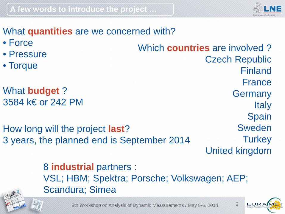
A few words to introduce the project …
What quantities are we concerned with? • Force • Pressure • Torque
Which countries are involved ? Czech Republic
Finland France
Germany Italy
Spain Sweden
Turkey United kingdom
What budget ? 3584 k€ or 242 PM
How long will the project last? 3 years, the planned end is September 2014
8 industrial partners : VSL; HBM; Spektra; Porsche; Volkswagen; AEP; Scandura; Simea
8th Workshop on Analysis of Dynamic Measurements / May 5-6, 2014
4
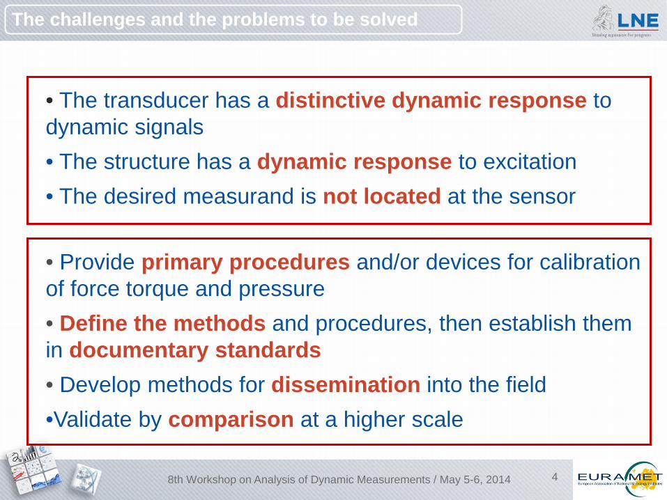
The challenges and the problems to be solved
• The transducer has a distinctive dynamic response to dynamic signals • The structure has a dynamic response to excitation • The desired measurand is not located at the sensor
• Provide primary procedures and/or devices for calibration of force torque and pressure • Define the methods and procedures, then establish them in documentary standards • Develop methods for dissemination into the field •Validate by comparison at a higher scale
8th Workshop on Analysis of Dynamic Measurements / May 5-6, 2014
5
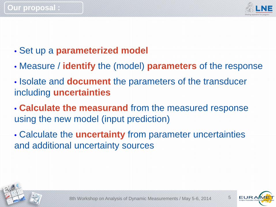
Our proposal :
• Set up a parameterized model • Measure / identify the (model) parameters of the response
• Isolate and document the parameters of the transducer including uncertainties • Calculate the measurand from the measured response using the new model (input prediction)
• Calculate the uncertainty from parameter uncertainties and additional uncertainty sources
8th Workshop on Analysis of Dynamic Measurements / May 5-6, 2014
6
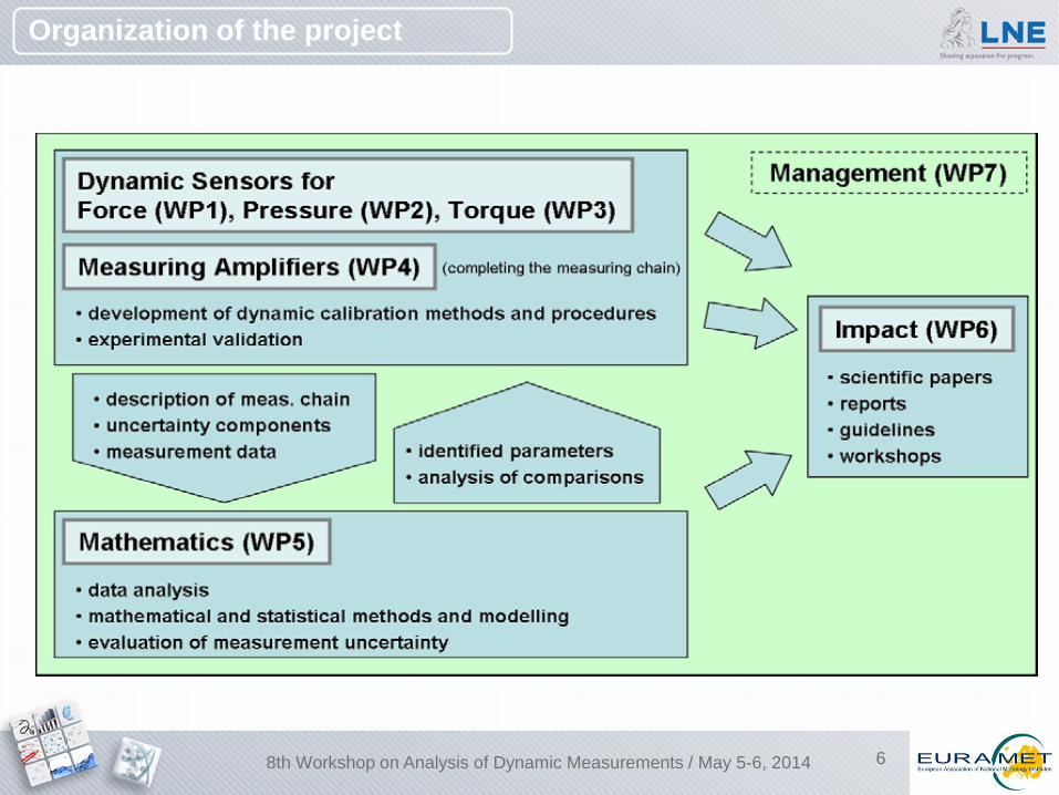
Organization of the project
8th Workshop on Analysis of Dynamic Measurements / May 5-6, 2014
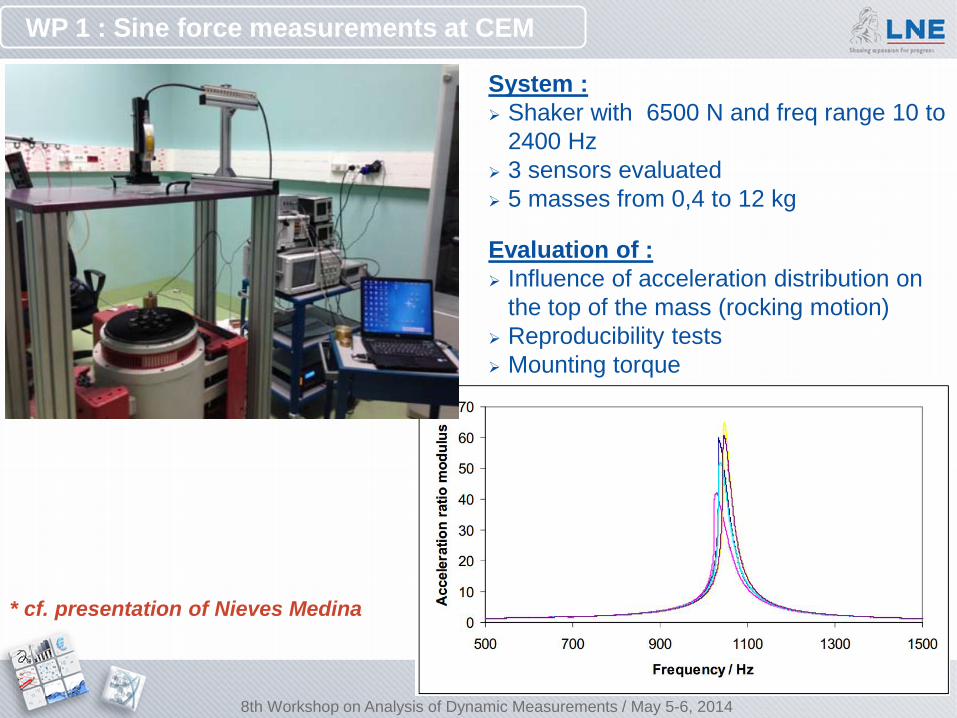
WP 1 : Sine force measurements at CEM
System : Shaker with 6500 N and freq range 10 to
2400 Hz 3 sensors evaluated 5 masses from 0,4 to 12 kg Evaluation of : Influence of acceleration distribution on
the top of the mass (rocking motion) Reproducibility tests Mounting torque
* cf. presentation of Nieves Medina
8th Workshop on Analysis of Dynamic Measurements / May 5-6, 2014
8
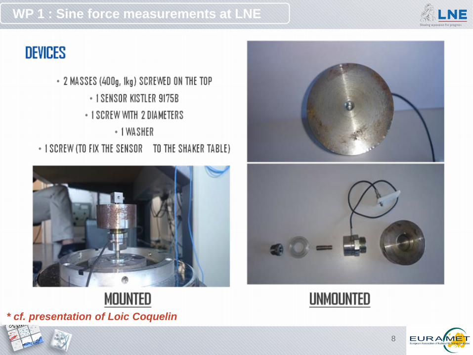
WP 1 : Sine force measurements at LNE
* cf. presentation of Loic Coquelin
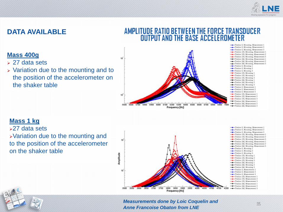
DATA AVAILABLE Mass 400g 27 data sets Variation due to the mounting and to
the position of the accelerometer on the shaker table
Mass 1 kg 27 data sets Variation due to the mounting and to the position of the accelerometer on the shaker table
Measurements done by Loic Coquelin and Anne Francoise Obaton from LNE
10
Current steps in sine force
- A design of experiments was realized to evaluate influence of : Mounting/unmounting sensors (applied torque on shaker/force sensor and force sensor/top mass) Weight of the top mass Position of the base accelerometer on the shaker table
- Comparison of the results from the 3 participants : Evaluation of the influence of theses parameters through a statistical model Integrate them as an uncertainty components for the estimation of the 3 parameters linked to the sensor and the 2 linked to its coupling.
- Dissemination of the calibration results and parameter identification to the secondary level
8th Workshop on Analysis of Dynamic Measurements / May 5-6, 2014
* cf. presentation of Christian Schlegel on primary and secondary periodic calibration of force transducers
11
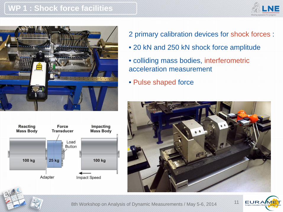
2 primary calibration devices for shock forces :
• 20 kN and 250 kN shock force amplitude
• colliding mass bodies, interferometric acceleration measurement
• Pulse shaped force
WP 1 : Shock force facilities
8th Workshop on Analysis of Dynamic Measurements / May 5-6, 2014
12
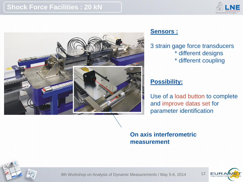
On axis interferometric measurement
Sensors : 3 strain gage force transducers * different designs * different coupling
Possibility: Use of a load button to complete and improve datas set for parameter identification
Shock Force Facilities : 20 kN
8th Workshop on Analysis of Dynamic Measurements / May 5-6, 2014
13
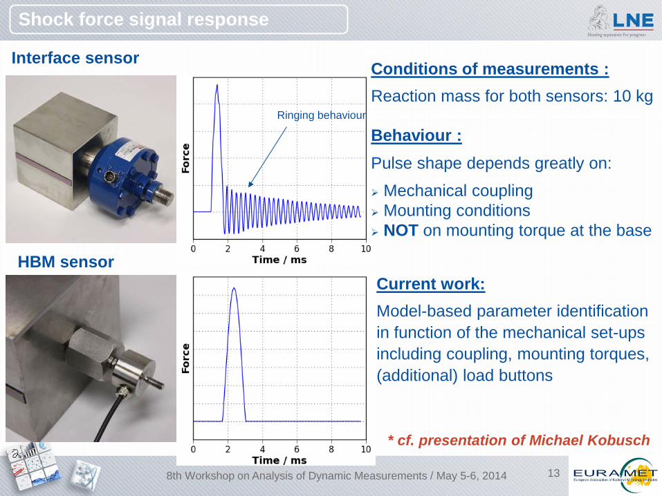
Interface sensor
Ringing behaviour
Behaviour : Pulse shape depends greatly on: Mechanical coupling Mounting conditions NOT on mounting torque at the base
Shock force signal response
HBM sensor
Conditions of measurements : Reaction mass for both sensors: 10 kg
Current work: Model-based parameter identification in function of the mechanical set-ups including coupling, mounting torques, (additional) load buttons
* cf. presentation of Michael Kobusch
8th Workshop on Analysis of Dynamic Measurements / May 5-6, 2014
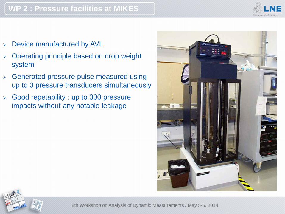
WP 2 : Pressure facilities at MIKES
Device manufactured by AVL
Operating principle based on drop weight system
Generated pressure pulse measured using up to 3 pressure transducers simultaneously
Good repetability : up to 300 pressure impacts without any notable leakage
8th Workshop on Analysis of Dynamic Measurements / May 5-6, 2014
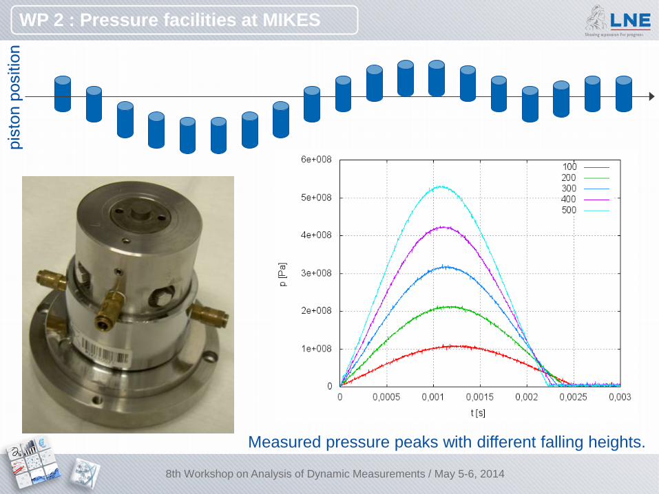
Measured pressure peaks with different falling heights.
pist
on p
ositi
on
WP 2 : Pressure facilities at MIKES
8th Workshop on Analysis of Dynamic Measurements / May 5-6, 2014
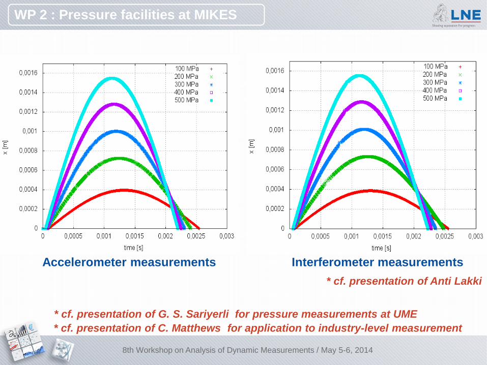
Accelerometer measurements Interferometer measurements
WP 2 : Pressure facilities at MIKES
* cf. presentation of Anti Lakki
8th Workshop on Analysis of Dynamic Measurements / May 5-6, 2014
* cf. presentation of G. S. Sariyerli for pressure measurements at UME * cf. presentation of C. Matthews for application to industry-level measurement
17
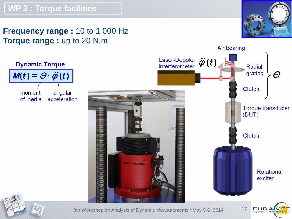
Frequency range : 10 to 1 000 Hz Torque range : up to 20 N.m
WP 3 : Torque facilities
8th Workshop on Analysis of Dynamic Measurements / May 5-6, 2014
18
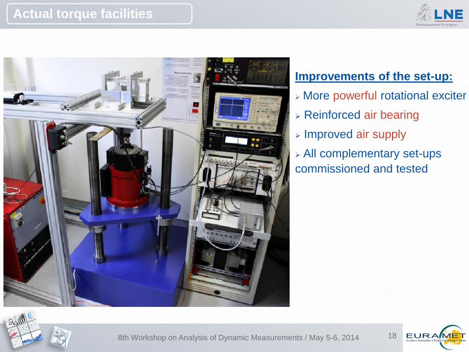
Actual torque facilities
Improvements of the set-up: More powerful rotational exciter Reinforced air bearing Improved air supply All complementary set-ups commissioned and tested
8th Workshop on Analysis of Dynamic Measurements / May 5-6, 2014
19
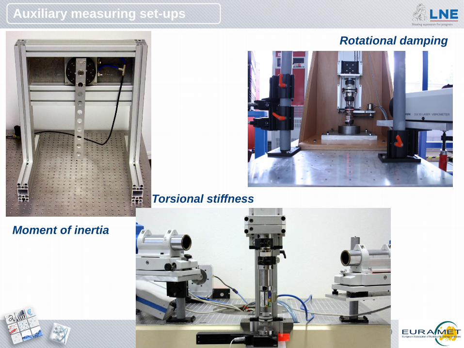
Torsional stiffness
Moment of inertia
Rotational damping
Auxiliary measuring set-ups
20
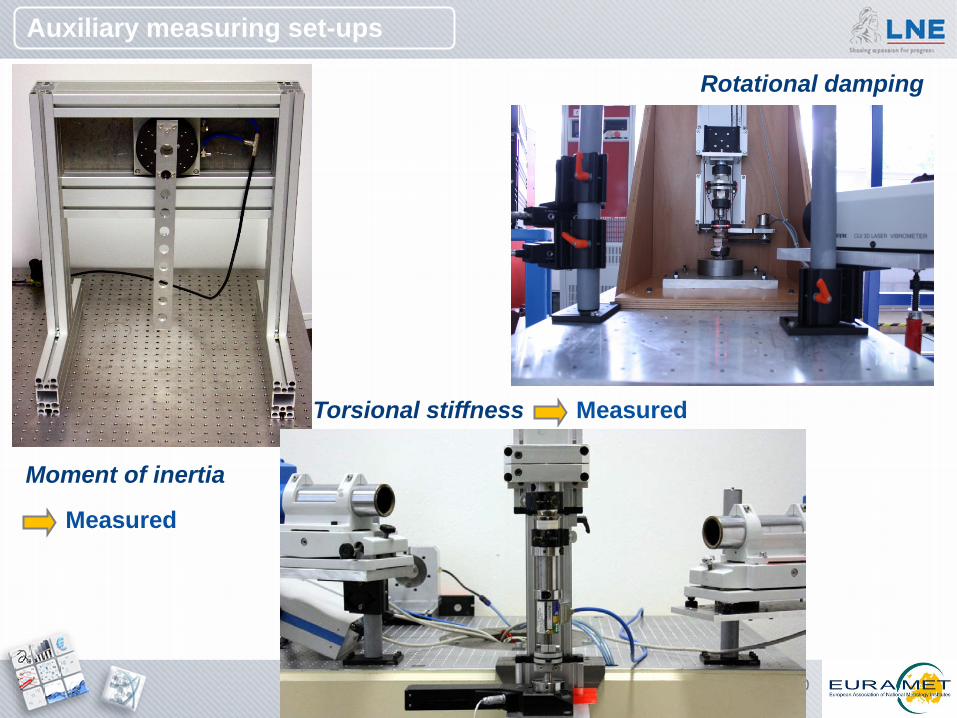
Torsional stiffness
Moment of inertia
Auxiliary measuring set-ups
Rotational damping
Measured
Measured
21
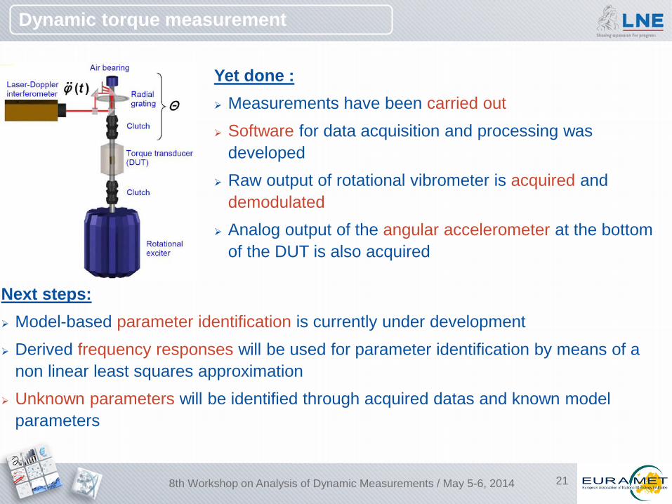
Dynamic torque measurement
Yet done : Measurements have been carried out Software for data acquisition and processing was
developed Raw output of rotational vibrometer is acquired and
demodulated Analog output of the angular accelerometer at the bottom
of the DUT is also acquired
Next steps: Model-based parameter identification is currently under development Derived frequency responses will be used for parameter identification by means of a
non linear least squares approximation Unknown parameters will be identified through acquired datas and known model
parameters
8th Workshop on Analysis of Dynamic Measurements / May 5-6, 2014
22
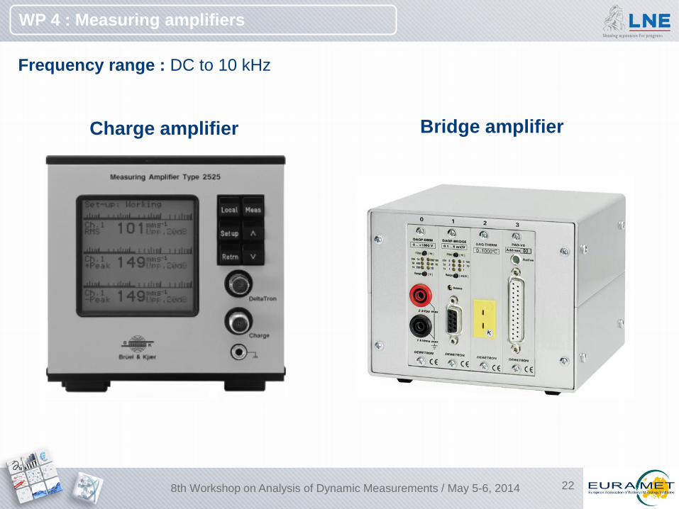
Frequency range : DC to 10 kHz
Charge amplifier Bridge amplifier
WP 4 : Measuring amplifiers
8th Workshop on Analysis of Dynamic Measurements / May 5-6, 2014
23
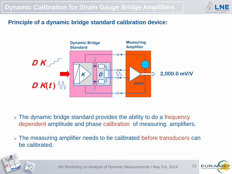
Dynamic Calibration for Strain Gauge Bridge Amplifiers
Principle of a dynamic bridge standard calibration device:
Measuring Amplifier
mV/V
Dynamic Bridge Standard System
D·K
D·K(t ) D K 2,000.0 mV/V
The dynamic bridge standard provides the ability to do a frequency dependent amplitude and phase calibration of measuring amplifiers.
The measuring amplifier needs to be calibrated before transducers can be calibrated.
8th Workshop on Analysis of Dynamic Measurements / May 5-6, 2014

24
Possible DynBN Calibration Strategies
Schematic operation principle of the PTB DynBN. Connected to a bridge amplifier, the DynBN simulates a dynamic strain gauge transducer output voltage.
Both components of the signal generation path (MDAC + resistive voltage divider) were calibration separately.
Since the DynBN phase is defined with respect to the MDAC generated reference signal, only the resistive voltage divider needs to be investigated for phase calibration.
8th Workshop on Analysis of Dynamic Measurements / May 5-6, 2014
25
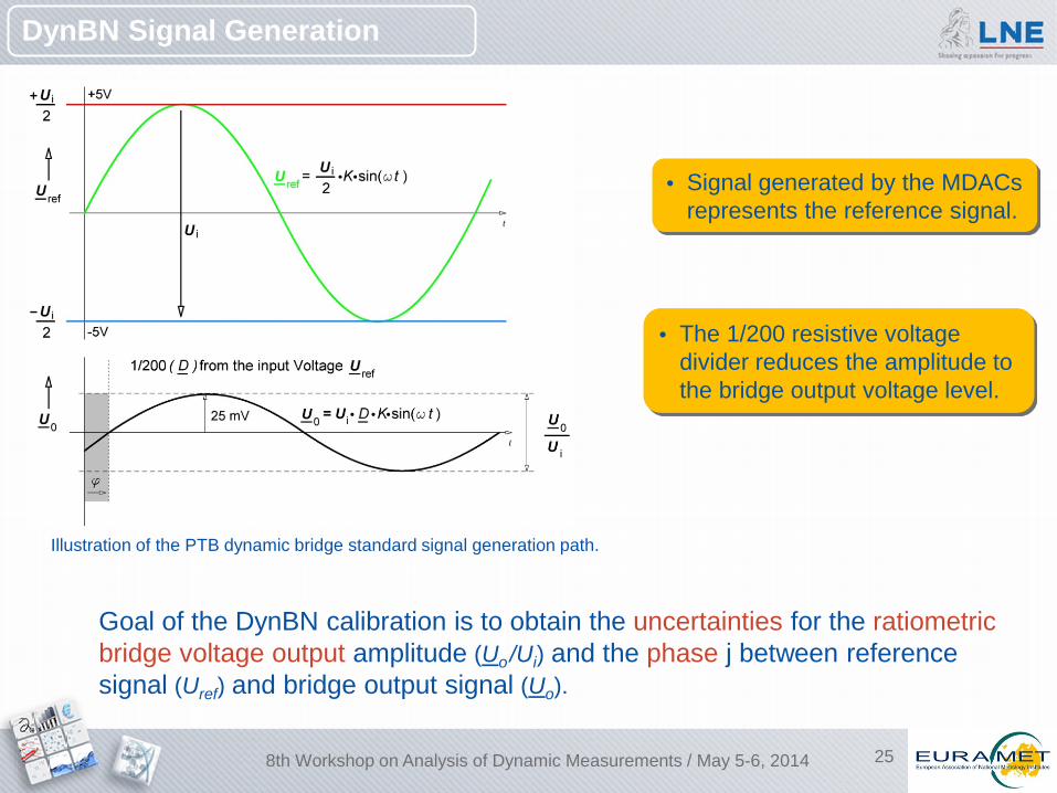
DynBN Signal Generation
Goal of the DynBN calibration is to obtain the uncertainties for the ratiometric bridge voltage output amplitude (Uo /Ui) and the phase j between reference signal (Uref) and bridge output signal (Uo).
Illustration of the PTB dynamic bridge standard signal generation path.
• Signal generated by the MDACs represents the reference signal.
• The 1/200 resistive voltage divider reduces the amplitude to the bridge output voltage level.
8th Workshop on Analysis of Dynamic Measurements / May 5-6, 2014
26
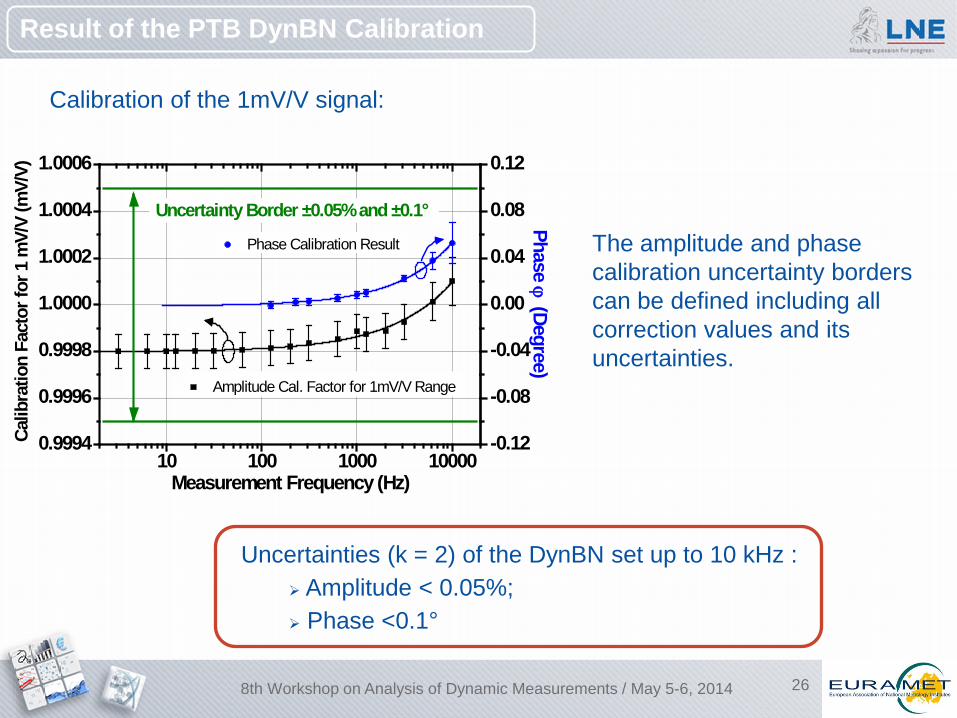
Result of the PTB DynBN Calibration
Calibration of the 1mV/V signal:
10 100 1000 100000.9994
0.9996
0.9998
1.0000
1.0002
1.0004
1.0006
-0.12
-0.08
-0.04
0.00
0.04
0.08
0.12
Calib
ratio
n Fa
ctor
for 1
mV/
V (m
V/V)
Measurement Frequency (Hz)
Amplitude Cal. Factor for 1mV/V Range
Phase ϕ (Degree)
Phase Calibration Result
Uncertainty Border ±0.05% and ±0.1°
The amplitude and phase calibration uncertainty borders can be defined including all correction values and its uncertainties.
Uncertainties (k = 2) of the DynBN set up to 10 kHz : Amplitude < 0.05%; Phase <0.1°
8th Workshop on Analysis of Dynamic Measurements / May 5-6, 2014
27
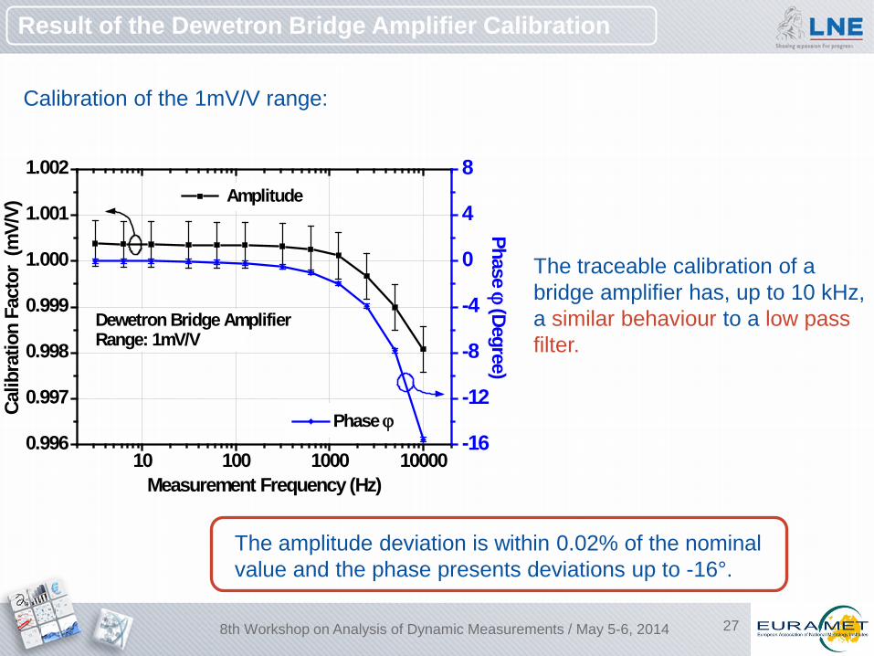
Calibration of the 1mV/V range:
10 100 1000 100000.996
0.997
0.998
0.999
1.000
1.001
1.002
-16
-12
-8
-4
0
4
8
Calib
ratio
n Fa
ctor
(m
V/V)
Measurement Frequency (Hz)
Amplitude
Phase ϕ
Phase ϕ (Degree)
Dewetron Bridge AmplifierRange: 1mV/V
Result of the Dewetron Bridge Amplifier Calibration
The traceable calibration of a bridge amplifier has, up to 10 kHz, a similar behaviour to a low pass filter.
The amplitude deviation is within 0.02% of the nominal value and the phase presents deviations up to -16°.
8th Workshop on Analysis of Dynamic Measurements / May 5-6, 2014
28
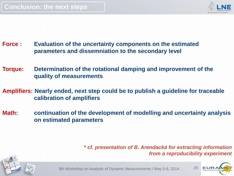
Force : Evaluation of the uncertainty components on the estimated parameters and dissemniation to the secondary level
Torque: Determination of the rotational damping and improvement of the quality of measurements
Amplifiers: Nearly ended, next step could be to publish a guideline for traceable calibration of amplifiers
Math: continuation of the development of modelling and uncertainty analysis on estimated parameters
Conclusion: the next steps
8th Workshop on Analysis of Dynamic Measurements / May 5-6, 2014
* cf. presentation of B. Arendacká for extracting information from a reproducibility experiment
To go further during this workshop …
Acknowledgements : The EMRP is jointly funded by the EMRP participating countries within EURAMET and the European Union.
B. Arendacká Extracting information from a reproducibility experiment
L. Coquelin Parameter identification for dynamic calibration of force transducers using sinusoidal excitations and assessment of the associated uncertainty
M. Kobusch Analysis of shock force measurements for the model-based dynamic calibration
A. Lakka Drop-weight system for dynamic pressure calibration
C. Matthews Dynamic pressure calibration: Application to industry-level measurement
N. Medina Dynamic calibration of force transducers at CEM
G. S. Sariyerli Measurement method for dynamic pressure sensors in Tubitak UME
C. Schlegel Primary and secondary periodic calibration of force transducers
30
Thanks for your attention !
8th Workshop on Analysis of Dynamic Measurements / May 5-6, 2014
Related Documents