State Machine Analysis and Design Z. Jerry Shi Computer Science and Engineering University of Connecticut University of Connecticut Thank John Wakerly for providing his slides and figures.

Welcome message from author
This document is posted to help you gain knowledge. Please leave a comment to let me know what you think about it! Share it to your friends and learn new things together.
Transcript

State Machine Analysis and Design
Z. Jerry ShiComputer Science and Engineering
University of ConnecticutUniversity of Connecticut
Thank John Wakerly for providing his slides and figures.
Clocked synchronous sequential circuits
• A.k.a. “state machines”• Use edge-triggered flip-flopsUse edge triggered flip flops• All flip-flops are triggered from the same master clock signal, and
therefore all change state together
• Feedback sequential circuitsN li i fli fl d i f db k l– No explicit flip-flops; state stored in feedback loops• Example: edge-triggered D flip-flop itself (4 states)• Sections 7.9 (advanced courses)

Describing Sequential Circuits
• State table– For each current-state, specify next-states as function of inputsFor each current state, specify next states as function of inputs– For each current-state, specify outputs as function of inputs
• State diagram– Graphical version of state table State/output table

State-machine structure (Mealy)
output depends onstate and inputp
typically edge-triggered D flip-flopsp ops

State-machine structure (Moore)
output dependson state onlyy
typically edge-triggered D flip-flopsp ops
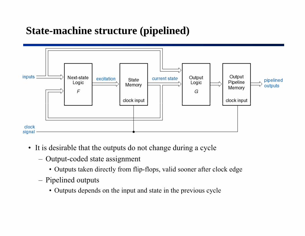
State-machine structure (pipelined)
• It is desirable that the outputs do not change during a cycle– Output-coded state assignmentp g
• Outputs taken directly from flip-flops, valid sooner after clock edge– Pipelined outputs
• Outputs depends on the input and state in the previous cycleOutputs depends on the input and state in the previous cycle

Notation, characteristic equations
• Q∗ means “the next value of Q.”• “Excitation” is the input applied to a device that determines theExcitation is the input applied to a device that determines the
next state.• “Characteristic equation” specifies the next state of a device as a
function of its excitation.

Latch and flip-flop characteristic equations

State-machine analysis steps
Assumption: Starting point is a logic diagram.1 Determine next-state function F and output function G1. Determine next state function F and output function G.2a. Construct state table
– For each state/input combination, determine the excitation value.
– Using the characteristic equation, determine the corresponding next-state values (trivial with D flip-flop’s).next state values (trivial with D flip flop s).
2b. Construct output table– For each state/input combination, determine the output value.
(Can be combined with state table.)3. (Optional) Draw state diagram
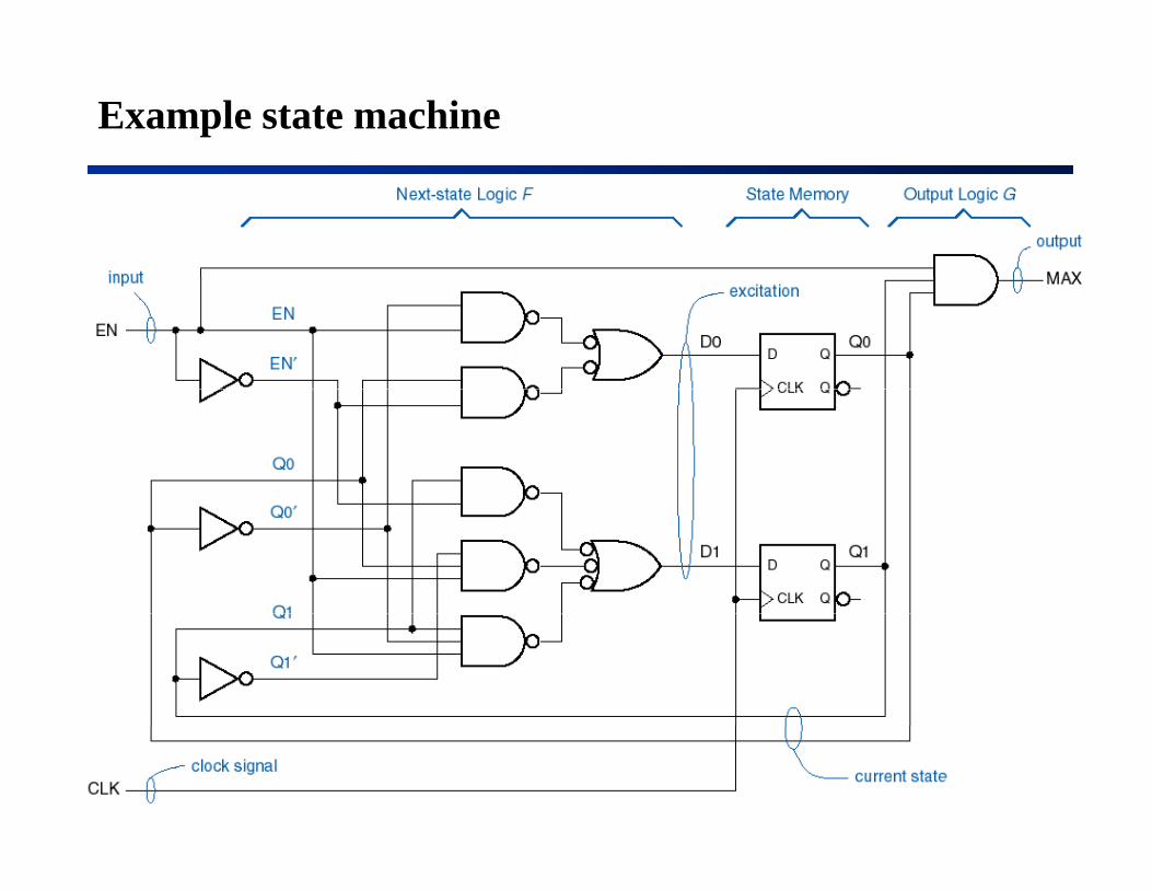
Example state machine
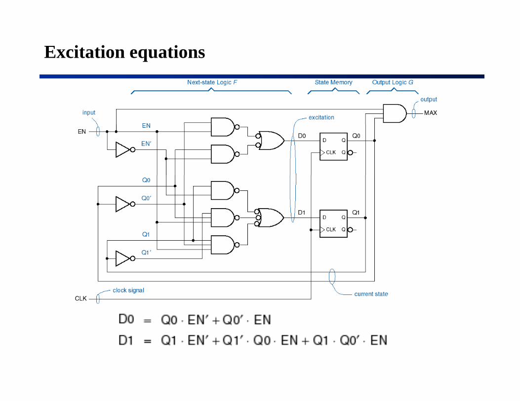
Excitation equations
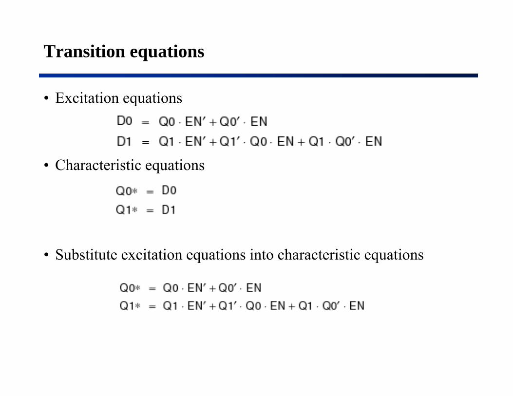
Transition equations
• Excitation equations
• Characteristic equationsq
• Substitute excitation equations into characteristic equations

Transition and state tables
(Transition equations)
(Output equation)
Transition table State table State/output tableTransition table State table State/output table

State diagram
• Circles for states• Arrows for transitions (note output information)• Arrows for transitions (note output information)

Modified state machine
MAXS Q0 Q1
MAXS
MAXS = Q0 ⋅ Q1
• Moore machine

Updated state/output table, state diagram
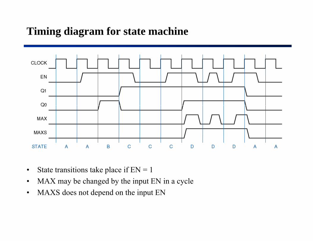
Timing diagram for state machine
• State transitions take place if EN = 1• MAX may be changed by the input EN in a cycle• MAXS does not depend on the input ENp p

State-machine design and synthesis
The creative part like Turning the crank like aThe creative part, like writing a program
Turning the crank, like a compiler does
• Example: Design a combination lock with two inputs X1 and X2• Example: Design a combination lock with two inputs, X1 and X2. Open for the sequence X1, X2, X2 (one input per clock).
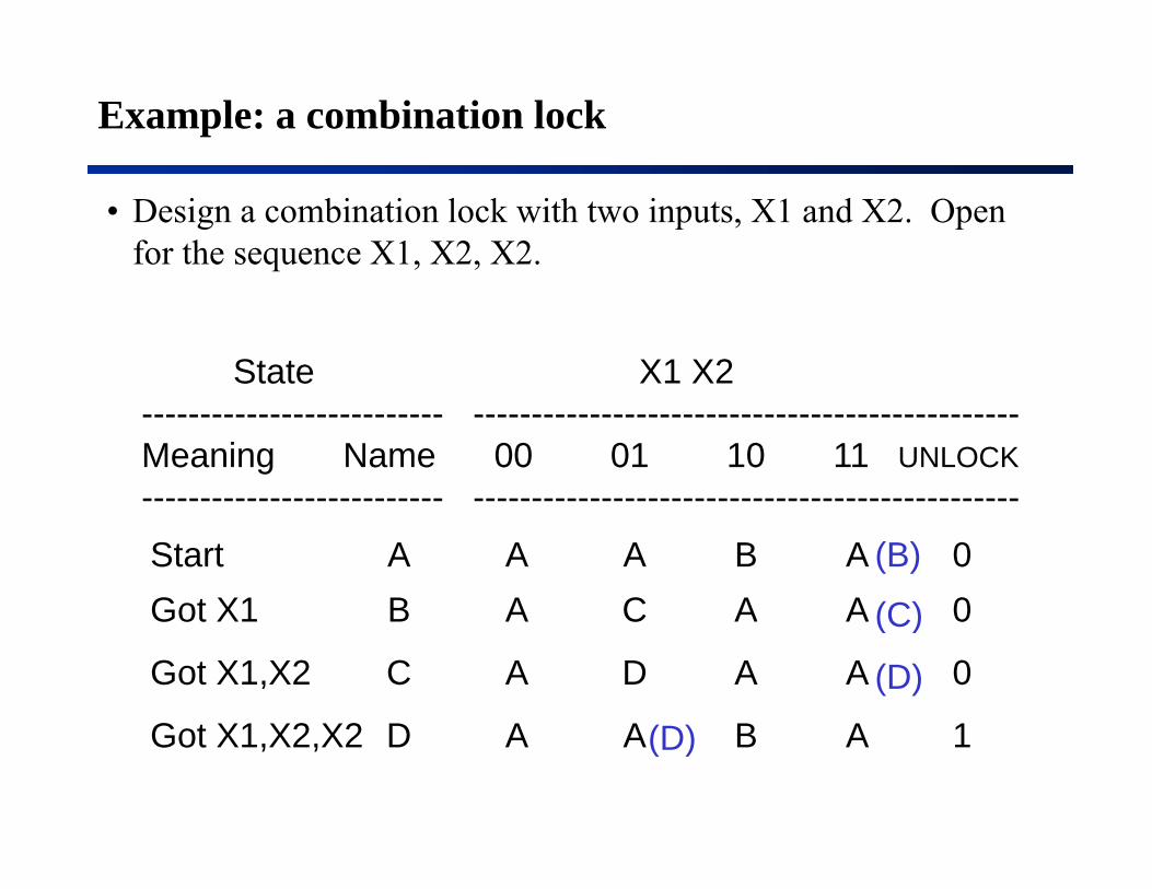
Example: a combination lock
• Design a combination lock with two inputs, X1 and X2. Open for the sequence X1, X2, X2.
State X1 X2-------------------------- -----------------------------------------------Meaning Name 00 01 10 11 UNLOCK-------------------------- ------------------------------------------------------------------------- -----------------------------------------------Start A A A B A 0Got X1 B A C A A 0(C)
(B)Got X1 B A C A A 0
Got X1,X2 C A D A A 0
G t X1 X2 X2 D A A B A 1(D)
(D)
(C)
Got X1,X2,X2 D A A B A 1(D)

State Assignment
• Can minimize number of states (see text), but hardly anyone bothers anymore.y
• Need to assign state-variable combinations to states.– Minimum number of variables for n states is ⎡log2 n⎤– Using more than minimum number may be advantageous in some
situations, e.g., one variable per state (“one-hot”) (see text).– Example -- 4 states, 2 state variables (Q1,Q2):p , (Q ,Q )
A ==> 00B ==> 01C ==> 10 Up to this point is “art”, the rest C ==> 10D ==> 11 is just “turning the crank.”

Transition table
• Substitute state-variable combinations for states in the state table.
State X1 X2-------------------------- -----------------------------------------------Meaning Q1 Q2 00 01 10 11 UNLOCK-------------------------- -----------------------------------------------St t 0 0 0 0 0 0 0 1 0 0 0Start 0 0 0 0 0 0 0 1 0 0 0Got X1 0 1 0 0 1 0 0 0 0 0 0
Got X1,X2 1 0 0 0 1 1 0 0 0 0 0
Got X1,X2,X2 1 1 0 0 0 0 0 1 0 0 1----------------------------------------------
Q1∗ Q2∗
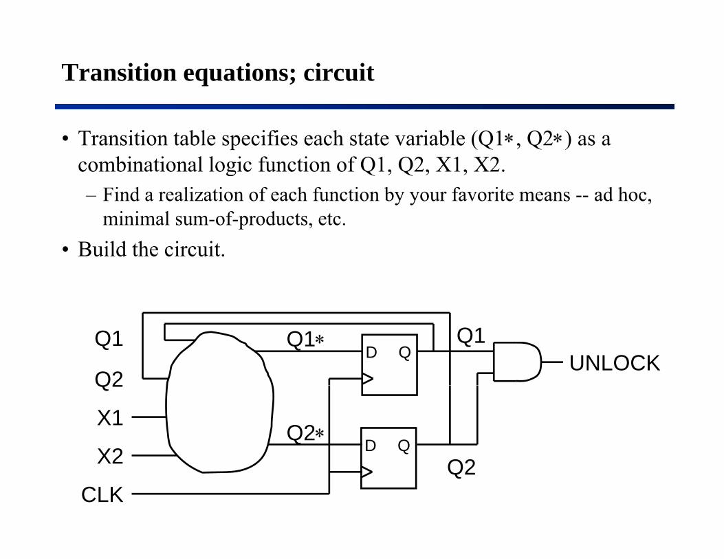
Transition equations; circuit
• Transition table specifies each state variable (Q1∗, Q2∗) as a combinational logic function of Q1, Q2, X1, X2.g Q , Q , ,– Find a realization of each function by your favorite means -- ad hoc,
minimal sum-of-products, etc.B ild th i it• Build the circuit.
UNLOCKD QQ1
Q2
Q1Q1∗
D Q
Q2
X1
X2Q2∗
X2
CLKQ2

Another design example (from textbook)
• Design a machine with inputs A and B and output Z that is 1 if:– A had the same value at the two previous ticks, orA had the same value at the two previous ticks, or– B has been 1 since the last time the above was true
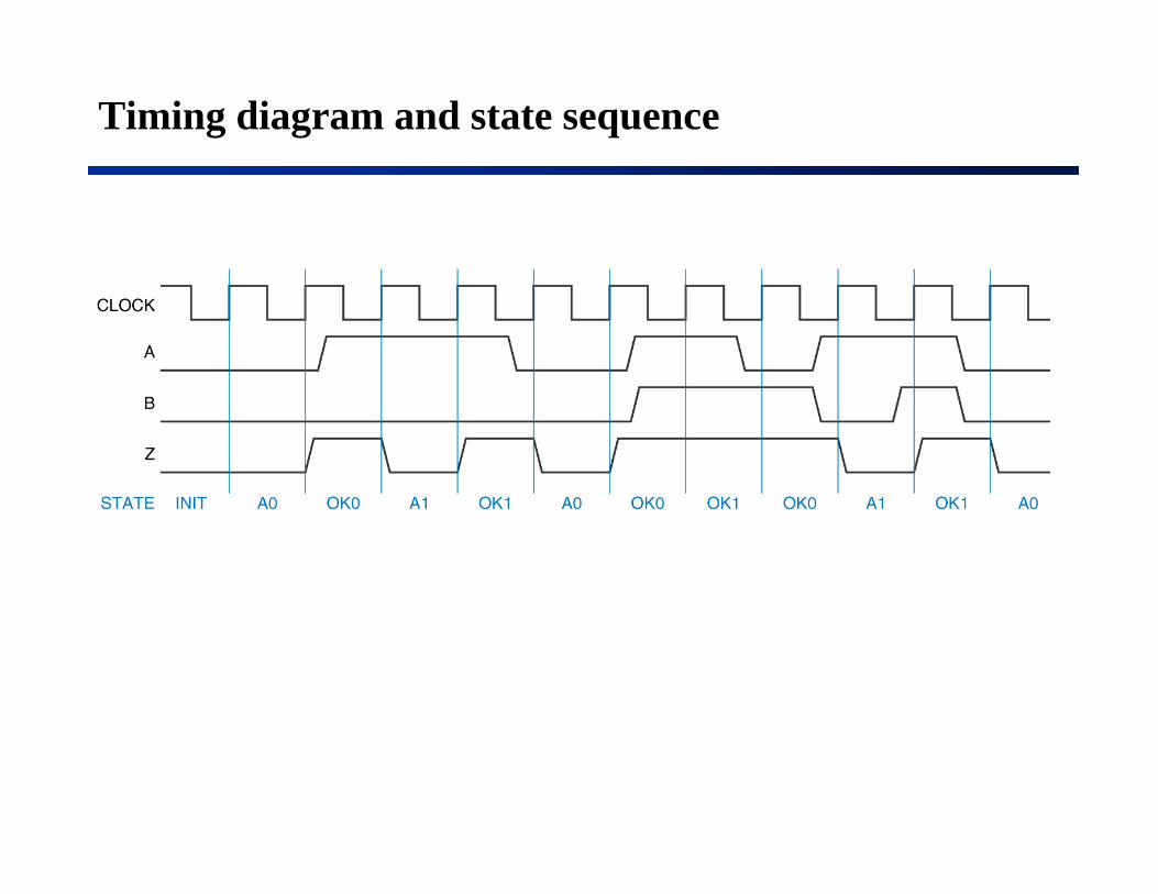
Timing diagram and state sequence

State assignment
• There are 6,720 different state assignments of 5 states to 3 variables.– And there are even more using 4 or more variables
• Here are a few “obvious” or “interesting” ones:

Transition/output table (decomposed assignment)
• Simple textual substitution• With D flip-flops, excitation table is identical to transition table.

Develop excitationDevelop excitation equations
• Assume unused states have next-state = 000

Don’t cares for the next-state entries of unused states
D1 = 1
D2 = Q1•Q3’•A’+Q3•A+ Q2•B
D3 = A
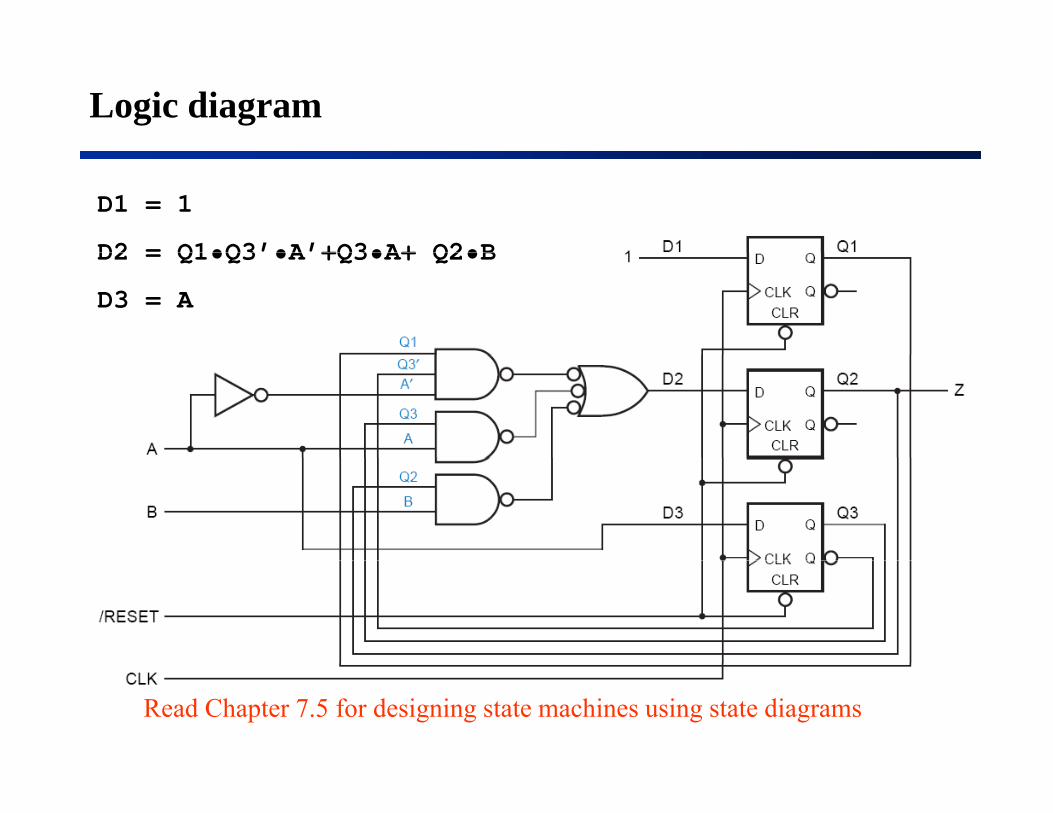
Logic diagram
D1 = 1
D2 = Q1•Q3’•A’+Q3•A+ Q2•BD2 = Q1•Q3 •A +Q3•A+ Q2•B
D3 = A
Read Chapter 7.5 for designing state machines using state diagrams
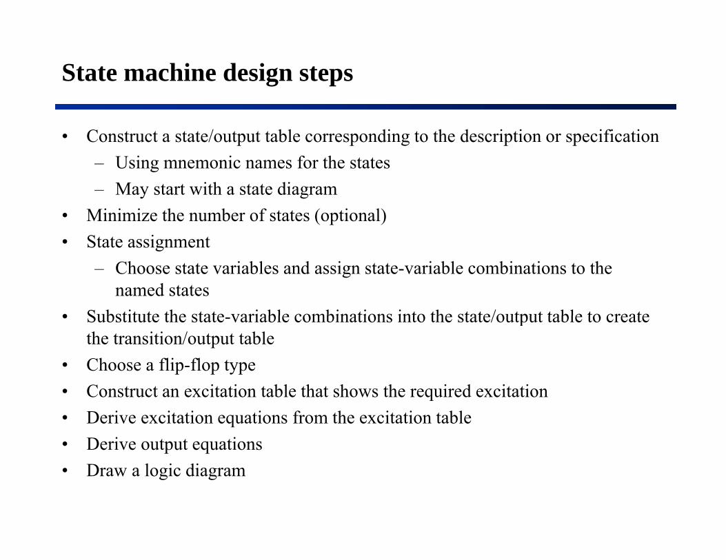
State machine design steps
• Construct a state/output table corresponding to the description or specification– Using mnemonic names for the states– May start with a state diagram
• Minimize the number of states (optional)• State assignmentState assignment
– Choose state variables and assign state-variable combinations to the named states
• Substitute the state variable combinations into the state/output table to create• Substitute the state-variable combinations into the state/output table to create the transition/output table
• Choose a flip-flop typeC t t it ti t bl th t h th i d it ti• Construct an excitation table that shows the required excitation
• Derive excitation equations from the excitation table• Derive output equations• Draw a logic diagram
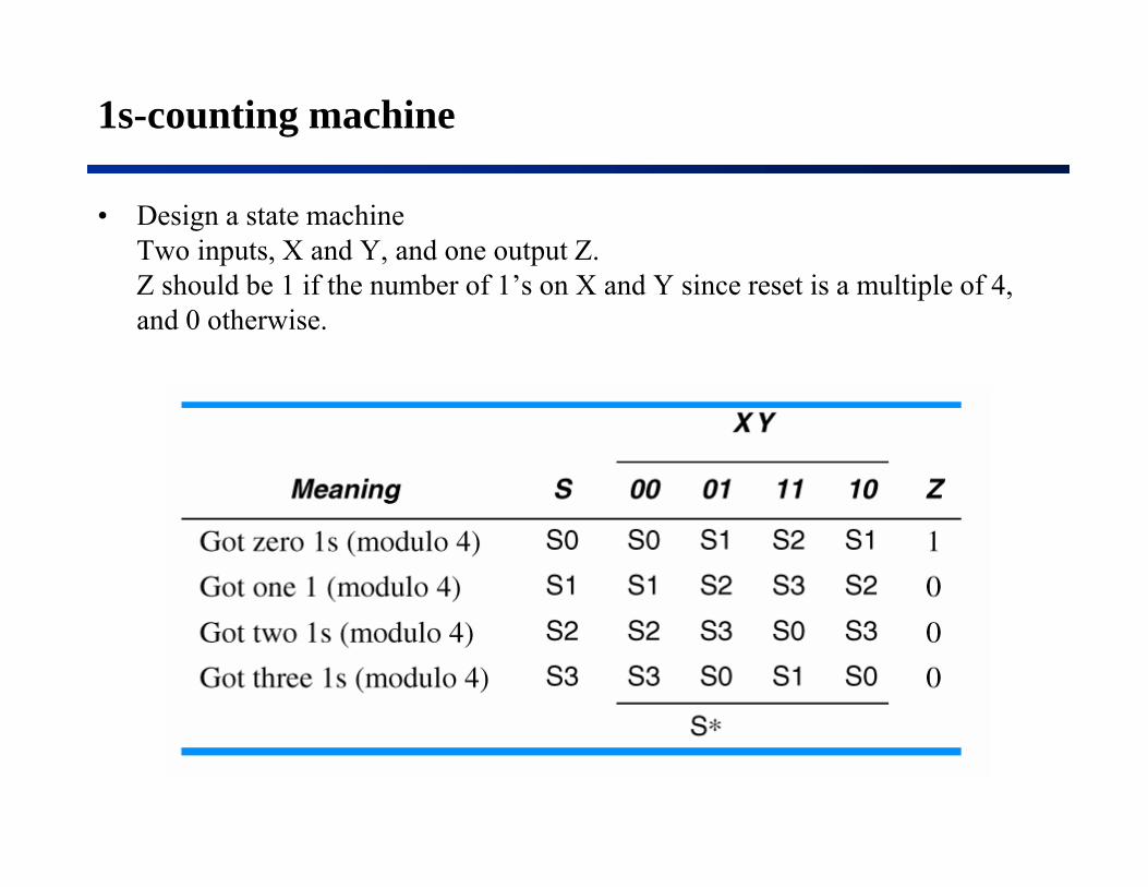
1s-counting machine
• Design a state machine Two inputs, X and Y, and one output Z. Z h ld b 1 if h b f 1’ X d Y i i l i l f 4Z should be 1 if the number of 1’s on X and Y since reset is a multiple of 4, and 0 otherwise.
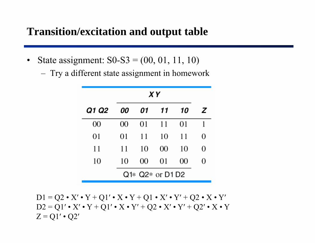
Transition/excitation and output table
• State assignment: S0-S3 = (00, 01, 11, 10)– Try a different state assignment in homeworkTry a different state assignment in homework
D1 = Q2 • X′ • Y + Q1′ • X • Y + Q1 • X′ • Y′ + Q2 • X • Y′D1 Q2 • X • Y + Q1 • X • Y + Q1 • X • Y + Q2 • X • Y D2 = Q1′ • X′ • Y + Q1′ • X • Y′ + Q2 • X′ • Y′ + Q2′ • X • Y Z = Q1′ • Q2′
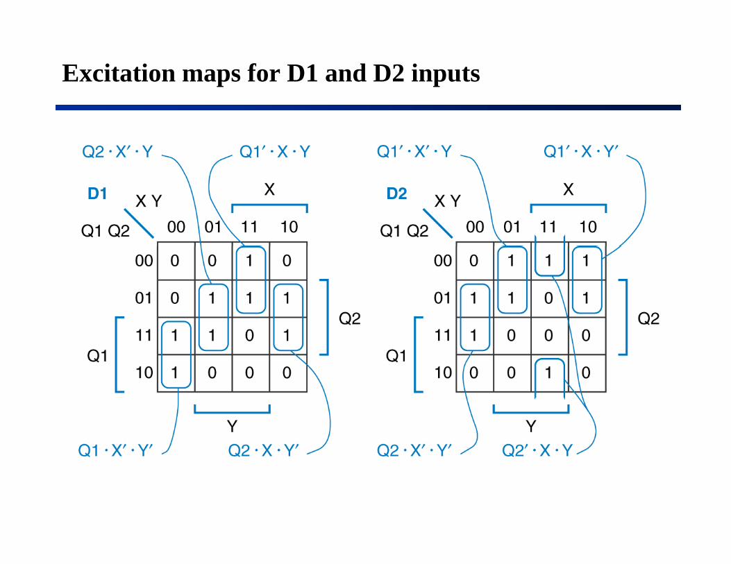
Excitation maps for D1 and D2 inputs

Combinational lock
• Design a state machine
O i XOne input X. Two outputs UNLK and HINT.
UNLK is 1 if and only if X is 0UNLK is 1 if and only if X is 0 and the sequence received on X at the preceding seven clock ticks was 0110111was 0110111.
HINT is 1 if and only if the current value of X is the correct one to move the machine closer to being in the “unlocked” state (where UNLK = 1).

Transition/excitation and output table
• State assignmentA - H : 0 - 7A H : 0 7
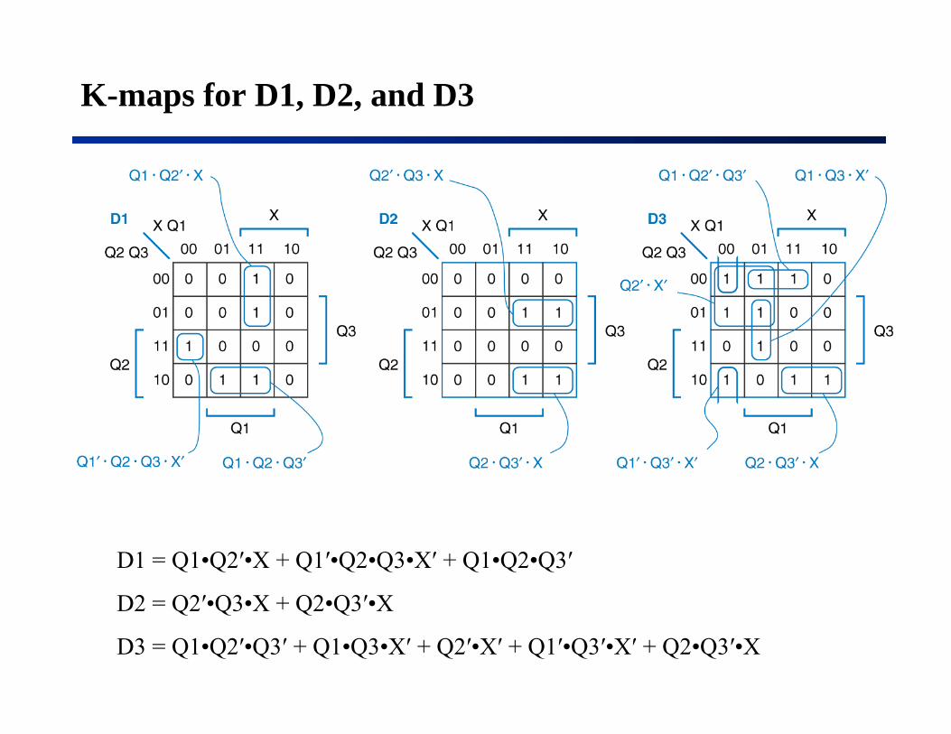
K-maps for D1, D2, and D3
D1 = Q1•Q2′•X + Q1′•Q2•Q3•X′ + Q1•Q2•Q3′
D2 Q2′ Q3 X + Q2 Q3′ XD2 = Q2′•Q3•X + Q2•Q3′•X
D3 = Q1•Q2′•Q3′ + Q1•Q3•X′ + Q2′•X′ + Q1′•Q3′•X′ + Q2•Q3′•X

K-maps for UNLK and HINT
UNLK = Q1•Q2•Q3•XQ Q Q
HINT = Q1′•Q2′•Q3′•X′ + Q1•Q2′•X + Q2′•Q3•X + Q2•Q3•X′+ Q2•Q3′•X
Another example
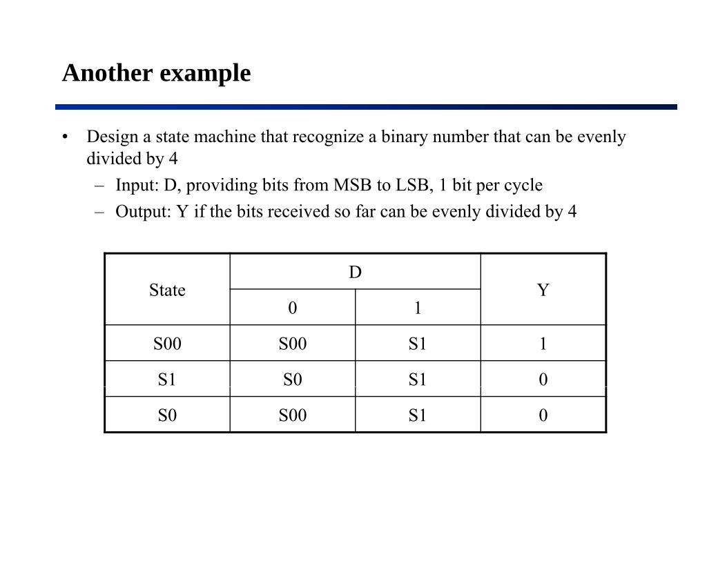
• Design a state machine that recognize a binary number that can be evenly divided by 4– Input: D, providing bits from MSB to LSB, 1 bit per cycle– Output: Y if the bits received so far can be evenly divided by 4
StateD
Y0 1
S00 S00 S1 1
S1 S0 S1 0
S0 S00 S1 0

Design State Machines using State Diagrams
• Sometimes people like graphical approaches– It is simplerIt is simpler
• However, it is also more error prone– A state table is an exhaustive listings of the next state for each
state/input combination• You will not miss a caseYou will not miss a case
– In a stage diagram, every input combination should be covered exactly by one expression
Gi i bi i d l i i• Given an input combination, one and only one expression is true• It is not easy to see

Ambiguity in state diagram
• In a properly constructed state diagram, each input combination is covered exactly once by an expression of an outgoing arcy y p g g
• Ambiguous: double-covered or uncovered• Some input combinations are covered by more than one
expressions (double-covered)– Given such an input combination, you have two or more transitions to
follow– AND of any two expressions should be 0
• Some input combinations are not covered by any expressions (uncovered)(uncovered)– Given such an input combination, you do not have any transitions to
follow– OR of all expressions should be 1

Example of an ambiguous state diagram

1965 Ford Thunderbird tail lights

Flashing sequence for T-bird tail-lights
Left turn Right turn

State diagram for T-bird tail-lights state machine
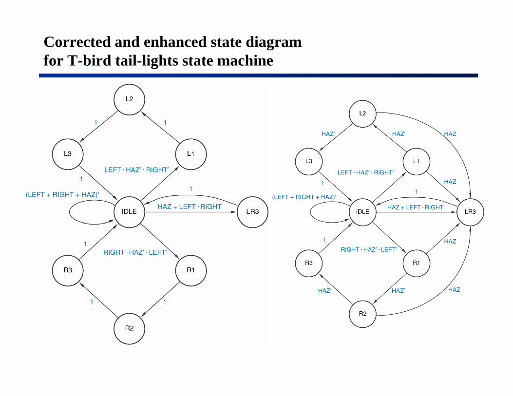
Corrected and enhanced state diagram for T-bird tail-lights state machine
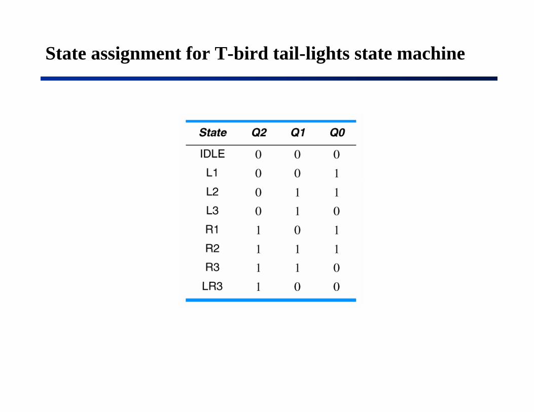
State assignment for T-bird tail-lights state machine
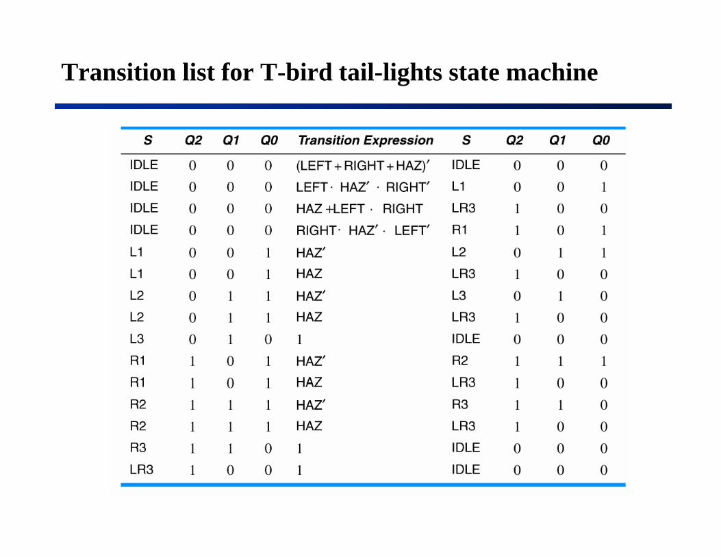
Transition list for T-bird tail-lights state machine
Related Documents