1 Shanghai Jiao Tong University Yikai Su State Key Lab of Advanced Optical Communication Systems and Networks , Department of Electronic Engineering, Shanghai Jiao Tong University, China [email protected] System applications of silicon photonic ring resonators

Welcome message from author
This document is posted to help you gain knowledge. Please leave a comment to let me know what you think about it! Share it to your friends and learn new things together.
Transcript

1 Shanghai Jiao Tong University
Yikai Su
State Key Lab of Advanced Optical Communication Systems and Networks ,
Department of Electronic Engineering, Shanghai Jiao Tong University, China
System applications of silicon photonic
ring resonators

2 Shanghai Jiao Tong University
Motivation
Electronic processing Optical processing in silicon
photonics
Complexity (# of units) High Low
Line width 10’s nm >100 nm
Power mW - W mW - W
Speed Gb/s Gb/s-Tb/s
Optical processing may be
desired in some high-speed
applications

3 Shanghai Jiao Tong University
Parameters of digital differentiator
Filter A/D DSP chip D/A Filter
memory I/O
Realization of digital differentiator using DSP
TMS320C6455 DSP ADC:MAX109
Speed:2.2 Gs/s
Power dissipation:6.8 W
Size:734.4 mm2
DAC:MAX5881
Speed:4.3 Gs/s
Power dissipation:1160 mW
Size:11 mmx11 mm
DSP:TMS320C6455
Speed:
1.2 GHz clock rate; 9600MIPS (16bit)
Size:
0.09-um/7-level Cu Metal Process (CMOS)
BGA package: 24*24 mm2
Power dissipation:1.76 W

4 Shanghai Jiao Tong University
Optical processing using ring resonator
SEM photos of a silicon microring
resonator
250-nm thickness
450-nm width
Buffer layer: 3-µm silica
Mode area: ~ 0.1µm2
Air gap : ~100 nm
Silicon 250nm
Silica buffer layer 3μm
Silicon handing wafer
525 μm
Signal processing functions:
• Slow light (JSTQE 08)
• Fast light (OE 09)
• Wavelength conversion (APL 08)
• Format conversion (OL 09)
• Optical differentiation (OE 08)

5 Shanghai Jiao Tong University
Outline
Tunable delay in silicon ring resonators
• Optically tunable buffer for diverse modulation formats at 5-Gb/s
• Optically tunable phase shifter for 40-GHz microwave photonic
signal
Signal Conversions and Switching
• Dense wavelength conversion and multicasting in a resonance-
split silicon microring
• Wavelength selective switching
• Format conversions (NRZ to FSK, NRZ to AMI)
• Optical temporal differentiator
Concentric rings for bio-sensing
Conclusions

6 Shanghai Jiao Tong University
Outline
Tunable delay in silicon ring resonators
• Optically tunable buffer for diverse modulation formats at 5-Gb/s
• Optically tunable phase shifter for 40-GHz microwave photonic
signal
Signal Conversions and Switching
• Dense wavelength conversion and multicasting in a resonance-
split silicon microring
• Wavelength selective switching
• Format conversions (NRZ to FSK, NRZ to AMI)
• Optical temporal differentiator
Concentric rings for bio-sensing
Conclusions

7 Shanghai Jiao Tong University
Recent experiments on slow-light delay
in silicon nano-waveguides
Schemes Footprint
(mm2)
3dB Band
width Duration/Delay
Max storage
capacity (bits) Publication
SRS ~100GHz 3ps/ 4ps 1.3 Opt. Express
14(2006)
cascaded
microring
resonator
(APF / CROW)
0.09
0.045
54GHz
--
50ps/510ps
200ps/220ps
10 at 20bps
1 at 5bps
Nature Photonics
1(2007)
photonic crystal
(PC) ~260MHz 1.9ns/1.45ns <1
Nature Photonics
1(2007)
photonic crystal
coupled
waveguides
(PCCW)
12nm 0.8ps/40ps LEOS 2007
• Continuous tuning was not demonstrated
• Data format was limited to non return-to-zero (NRZ)

8 Shanghai Jiao Tong University
Tuning signal delay in resonator-
based slow-light structure
Tunable group delay is important for
implementing a practical buffer
Single microring-resonator is a basic building
block of the resonator-based slow-light structure
Tuning methods:
• Electro-optic effect by forming a p-i-n structure
• Thermo-optic effect by implanting a micro-heater
• MEMS actuated structure

9 Shanghai Jiao Tong University
Partial
coupling Input DI
More
coupling
Resonance
Incoming light is partially coupled into the ring
The signal in the ring interferes with the input
light after one round-trip time
Only the signal of resonance can be coupled
into the ring
Ring resonator

10 Shanghai Jiao Tong University
Slow light
Group delay
Also see the animation

11 Shanghai Jiao Tong University
Tunable slow-light in silicon ring resonator
Slow-light principle:
-1.5 -1.0 -0.5 0.0 0.5 1.0 1.5
-8
-6
-4
-2
0
× 10-4Normalized frequency detuning
Norm
ali
zad
tra
nsm
issi
on
(d
B)
(a)
0
1
2
3
4
5
6
Ph
ase
sh
ift
(rad
)
-1.5 -1.0 -0.5 0.0 0.5 1.0 1.50
20
40
60
80
100
120
140
× 10-4Normalized frequency detuning
Del
ay (
ps)
(b)
Δθ/Δω
= group delay
=> Slow light

12 Shanghai Jiao Tong University
When a pump light is injected into the microring resonator, the
absorbed energy is eventually converted to the thermal energy
and leads to a temperature shift
Ad T T P
dt CV
The refractive index changes with the temperature
4 11.86 10n k T
k K
τ- thermal dissipation time
ρ-density of the silicon
C-thermal capacity
V-volume of the microring
Kθ-thermo-optic coefficient
Temperature tuning
No need of additional procedure in the fabrication, very low
threshold in tuning

13 Shanghai Jiao Tong University
Silicon microring used in the experiment
SEM photos of the silicon microring resonator with a radius of 20 μm
250-nm thickness
450-nm width
Buffer layer: 3-µm silica
Mode area: ~ 0.1µm2
Air gap : 120 nm
Silicon 250nm
Silica buffer layer 3μm
Silicon handing wafer
525 μm
1552.6 1552.7 1552.8 1552.9 1553.0 1553.1
-8
-6
-4
-2
0
experimental data
curve fitting
wavelength (nm)
No
rma
lize
d t
ran
smis
sio
n(d
B)
~8-dB notch depth
~0.1-nm 3-dB bandwidth

14 Shanghai Jiao Tong University
Vertical coupling
Gold grating coupler to couple light between the
single mode fiber (SMF) and the silicon waveguide
The gold grating coupler is designed to support
TE mode only
Measured fiber-to-fiber coupling loss: ~20dB
The technique was invented by Ghent
SEM photo of the gold grating coupler

15 Shanghai Jiao Tong University
Experimental setup
A dual-drive MZM is used when
generating RZ-DB and RZ-AMI
CW laser
PPG
PCSingle drive
MZM
PC
EDFA EDFA
EDFA
RF
Single drive
MZM
BPF
BPF Attenuator
PRBS
Oscilloscope
PM
Coupler
PC
Attenuator
DPSK demodulation
generation of RZ / CSRZ signal
Fangfei Liu et al., IEEE JSTQE May/June 2008

16 Shanghai Jiao Tong University
Continuous Tuning of 5-Gb/s Non-
return-to-zero (NRZ) signal
-30 -20 -10 0 10 20
0
30
60
90
120 1G
5G
10G
Dela
y (
ps)
Pump power (dBm)
(a)
0 500 1000 1500 20000.0
0.5
1.0
1.5
2.0
2.5
Inte
nsity (
a.u
.)Time (ps)
-30.7dBm
4.8dBm
13.7dBm
(c)
Delay versus the pump power Delayed waveforms
(b)
Maximum delay of ~100 ps

17 Shanghai Jiao Tong University
-40 -30 -20 -10 0 10 20
0
30
60
90
120 1G
5G
De
lay (
ps)
Power (dBm)
(a)
0 100 200 300 400 5000.00
0.25
0.50
0.75
1.00 -37.0dBm
3.2dBm
13.6dBmIn
ten
sity
/ a
. u
Time / ps
(c)
Return-to-zero (RZ) signal
5Gb/s
5G RZ
eye diagram
Maximum delay of 80 ps
for 5-Gb/s RZ signal
Delay versus the pump power
Qiang Li et al., IEEE/OSA J. Lightw. Technol.,
Vol 26, No. 23, 2008

18 Shanghai Jiao Tong University
5-Gb/s carrier-suppressed RZ
(CSRZ) signal
Eye diagrams and waveforms for the 5-Gb/s CSRZ signal
Maximum delay of 95 ps
0 0
CSRZ is used in long haul

19 Shanghai Jiao Tong University
5-Gb/s RZ-Duobianry (DB) and RZ-
Alternating-Mark-Inversion (AMI) signals
RZ-DB
RZ-AMI
Maximum delay of 110 ps
Maximum delay of 65 ps
RZ-DB is good for dispersion
uncompensated system in
metro
RZ-AMI is tolerant to
nonlinear impairments

20 Shanghai Jiao Tong University
Delay comparisons
Formats NRZ RZ CSRZ RZ-DB RZ-AMI
Delays (ps) 100 80 95 110 65
Optical spectra
the narrower,
the larger delay
Qiang Li et al., OSA Slow and Fast Light Topic Meeting, 2008

21 Shanghai Jiao Tong University
Resonator-based slow-light structures :
Single channel side-coupled integrated spaced sequences of resonators (SCISSOR)
Double channel SCISSOR
Coupled resonator optical waveguides (CROW)
Larger delay with cascaded rings
Single channel SCISSOR
double channel SCISSOR
CROW

22 Shanghai Jiao Tong University
Optically tunable microwave
photonic phase shifter
Operation principle
Op
ical
spec
tru
m
Frequency
20G20G
10dB
Ein Eout
E(0)E(L)
-3 -2 -1 0 1 2 3
-6
-5
-4
-3
-2
-1
0
Normalized frequency detuning
Norm
ali
zed
tra
nsm
issi
on
(d
B)
0
1
2
3
4
5
6
Ph
ase sh
ift (rad
)
× 10-4
(b)
(a)
(c)
The two tones of the microwave optical signal experience different phase shifts, resulting in group delay change

23 Shanghai Jiao Tong University
Experimental setup
20-GHz microwave photonic signal
Temperature tuning
Silicon
microring
Q. Li et al., ECOC 2008, paper P2.12

24 Shanghai Jiao Tong University
40GHz result – phase shift
0.0 0.5 1.0 1.5 2.0
0.2
0.4
0.6
0.8
1.0
Norm
ali
zed
in
ten
sity
(a.u
.)
Time (ns)
-4.6rad
Maximum phase shift:
-4.6 rad
Qingjiang Chang et al., IEEE Photon. Technol. Lett,vol. 21, no. 1, Jan. 2009

25 Shanghai Jiao Tong University
6 8 10 12 14 16-5
-4
-3
-2
-1
0
(a)
Pump power (dBm)
Ph
ase
sh
ift
(ra
d)
4 6 8 10 12 14 160
1
2
3
4(b)
Pump power (dBm)
Ph
ase
sh
ift
(ra
d)
Phase shift vs. pump power
Continuous tuning based on thermal nonlinear effect by changing the control light power

26 Shanghai Jiao Tong University
Outline
Tunable delay in silicon ring resonators
• Optically tunable buffer for diverse modulation formats at 5-Gb/s
• Optically tunable phase shifter for 40-GHz microwave photonic
signal
Signal Conversions and Switching
• Dense wavelength conversion and multicasting in a resonance-
split silicon microring
• Wavelength selective switching
• Format conversions (NRZ to FSK, NRZ to AMI)
• Optical temporal differentiator
Concentric rings for bio-sensing
Conclusions

27 Shanghai Jiao Tong University
Signal conversions in mode-split ring
The transmission function of the ring resonator is given by:
0
0 0 0 0 0 00 0
1 11 ( )
2( ) ( )
2 2 2 2 2 2
t
i e
u i e u i e
s
s Qj j
Q Q Q Q Q Q
Mode a is split into two resonance frequencies, ω0-ω0/(2Qu) and
ω0+ω0/(2Qu). The resonance-splitting is determined by the mutual coupling
factor Qu.
si st
ab
ω0 - the resonance frequency
QE - coupling quality factor
QL – intrinsic quality factor
Qu – coupling quality factor
Side wall roughness in E-beam
results in two resonance modes:

28 Shanghai Jiao Tong University
Observation of mode splitting
Resonance-splitting
Motivation: shift the resonance to convert signals by
using free carrier dispersion (FCD) effect
Ziyang Zhang et al., CLEO/QELS 2008
Tao Wang et al., JLT 2009

29 Shanghai Jiao Tong University
Experimental results – dense
wavelength conversion of 0.4nm
nm
1. Signal light is originally set at
the resonance -> ‘0’
2. Resonance is shifted when
pump is ‘1’
3. Signal light off resonance ->
‘1’ -> wavelength conversion
4. Inverted case can be realized
pump signal
Qiang Li et al., App. Phy. Lett., 2008

30 Shanghai Jiao Tong University
Conversions of 2 wavelengths ->
wavelength multicasting
By setting the signal wavelengths
properly, non-inverted and inverted
multicasting can be implemented
Wavelength multicasting
s1 s2 p
FSR
Qiang Li et al., App. Phy. Lett., 2008

31 Shanghai Jiao Tong University
Format conversion- NRZ to FSK
500μW/div
2.5ns/div
FSK Eye diagram
5dB/div
0.5nm/div
FSK Spectrum
s1 s2 p
Input NRZ signal
demodulated signal: upper sideband
demodulated signal: upper sideband
500μW/div
500ps/div
Fangfei Liu et al., APOC 2008

32 Shanghai Jiao Tong University
Reconfigurable optical add-drop multiplexers
Ref: E. Basch, et.al, JSTQE, vol. 12, no. 4, 2006.
R
O
A
D
M
n
o
d
e
flexible management
reconfigurable provisioning
Increased capacity
Multiple services
ROADMs
Exchanging node
WDM optical network

33 Shanghai Jiao Tong University
Wavelength selective switch Wavelength selective switches (WSSs) are core components in ROADMs.
Ref: P. Colbourne and B. Collings, OFC 2011
ROADM node
Function of WSS
Flexible and reconfigurable
allocation of wavelength
channels among various
routes

34 Shanghai Jiao Tong University
Previous works on WSS
WSS based on MEMS WSS based on liquid crystal
Ref: 1. Joseph Ford, et.al, JLT, vol. 17, no. 5, 1999.
2. Yasuki Sakurai, et.al., PTL, vol. 23, no. 14, 2011.

35 Shanghai Jiao Tong University
Evolution of WSSes
Ref: P. Colbourne and B. Collings, OFC 2011
Developing trends of WSSs
1. Low-cost
2. Miniaturization
Merits of silicon devices
1. On-chip integration
2. Reduced sizes
Free-space
WSS
Discrete
wavelength filter
Liquid-crystal
WSS
On-chip
WSS
Mini
WSS

36 Shanghai Jiao Tong University
WSS using silicon microring resonators
Ref: Douwe Geuzebroek, et. al., PTL, vol. 17, no. 2,
(2005)

37 Shanghai Jiao Tong University
Proposed structure
silicon MRR with nested pair of subrings (NPS)

38 Shanghai Jiao Tong University
Simulated transmission spectra
λ1 λ2
λ1: blocked at OUT1 and routed to OUT2
λ2: blocked at OUT2 and routed to OUT1

39 Shanghai Jiao Tong University
Device fabrication
248-nm DUV lithography, ICP etching process, on SOI wafer
Thermal-optic micro-heaters are fabricated along the NPS to tune
the central wavelengths of the split resonances.

40 Shanghai Jiao Tong University
Measured spectra with one NPS
Switch off λ1 0 V Switch off λ2 0.4 V Switch off λ4 1.0 V Switch off λ3 0.7 V

41 Shanghai Jiao Tong University
Demonstration of dynamic channel-routing
10 Gb/s NRZ input signal

42 Shanghai Jiao Tong University
10-Gb/s NRZ signal from OUT1 port

43 Shanghai Jiao Tong University
10-Gb/s NRZ signal from OUT2 port

44 Shanghai Jiao Tong University
BER performances
1.0 dB and 0.8 dB power penalties at OUT1 and OUT2, respectively.

45 Shanghai Jiao Tong University
Optical temporal differentiator
:
In the critical coupling region
(QL = QE), the transfer function
of the microring resonator is:
0
0
2( ) ( )
QT j
A typical function for a first-
order temporal differentiator

46 Shanghai Jiao Tong University
Experimental results
50ps/div 50ps/div 50ps/div 50ps/div
50ps/div 50ps/div 100ps/div 100ps/div
100ps/div 50ps/div100ps/div 100ps/div
(a-i) (a-ii) (a-iii) (a-iv)
(b-i) (b-ii) (b-iii) (b-iv)
(c-i) (c-ii) (c-iii) (c-iii)
10G 5G
Gaussian
Sine
Square
Input Output Input Output
Fangfei Liu, et al., Opt. Express 2008

47 Shanghai Jiao Tong University
Format conversion- NRZ to AMI
0 400 800 1200 1600 20000.0
0.2
0.4
0.6
0.8
1.0
(a)
Nor
mal
ized
am
plit
ude
(a.u
.)
Time (ps)
0 400 800 1200 1600 20000.0
0.2
0.4
0.6
0.8
1.0(b)
Nor
mal
ized
am
plitu
de (
a.u.
)
Time (ps)
10G NRZ 10G AMI
A microring is a high pass filter
NRZ + high pass filtering => AMI
Qiang Li et al., Chin. Opt. Lett., Vol 7, No. 2, 2009
48 Shanghai Jiao Tong University
How to build an ultra-high-speed all-
optical differentiator?

49 Shanghai Jiao Tong University
80-G optical differentiator using a ring
resonator with 2.5-nm bandwidth
Radius: 20 μm
Bandwidth : 2.5 nm
Resonance wavelength: 1551.73nm

50 Shanghai Jiao Tong University
Measurement setup

51 Shanghai Jiao Tong University
80-Gb/s differentiation result
G. Zhou et al., Electron. Lett. 2011

52 Shanghai Jiao Tong University
Future work: 160-G differentiation
Design of new ring resonator: critical coupling, large 3-dB bandwidth
One possible design:
• Large bandwidth: small diameter and high loss
• Critical coupling: long coupling length
B3dB=5nm
53 Shanghai Jiao Tong University
Comparison of optical and
electronic differentiators
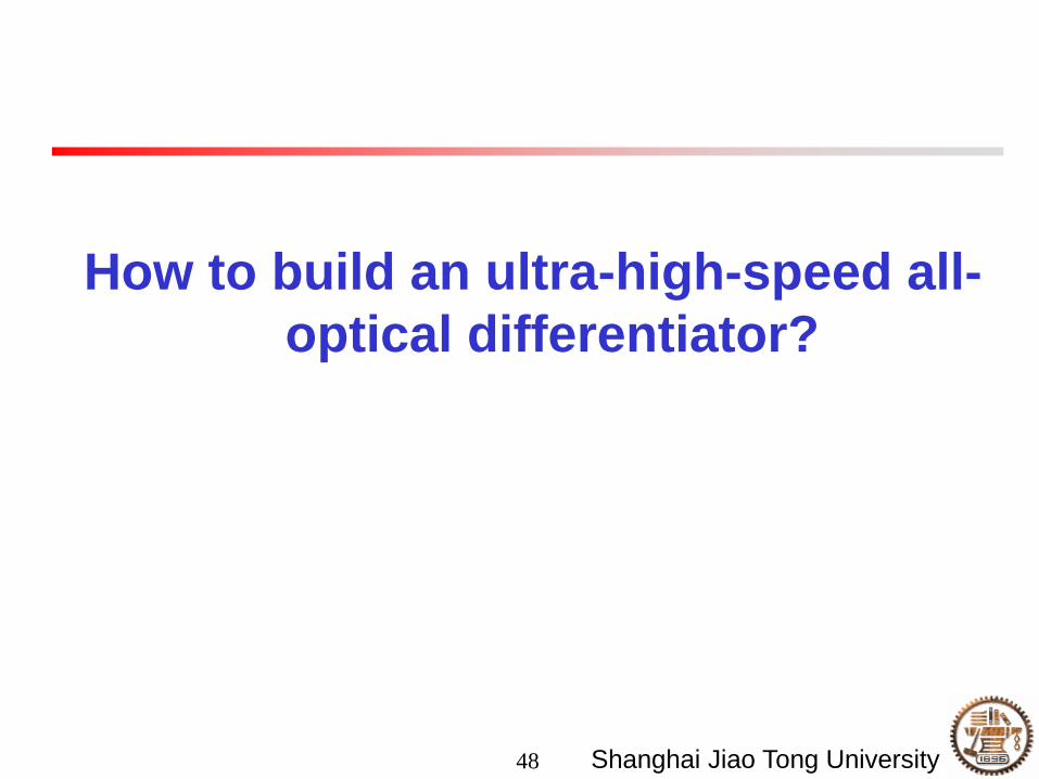
Species Speed Size Power dissipation
Silicon ring 80 Gbps or
higher
20 μm (radius) < 1 mW
Digital
differentiator
a few GHz mm2 a few W
All-optical differentiator: (1) ultra-high speed
(2) compact structure
DSP based: configurable; can fulfill more than one function

54 Shanghai Jiao Tong University
Differential equation solver
1 1
2 2
y xy
t t
d d
d d
Differential equations are widely employed in virtually any field of
science and technology:
• Physics
• Biology
• Chemistry
• Economics
• Engineering
All constant-coefficient linear differential equations can be modeled
with finite number of:
• Differentiators
• Couplers/Subtractors
• Splitters
• Feedback branches

55 Shanghai Jiao Tong University
Optical differential equation solver
output port
input port
optical
differentiator
+
-
optical input
signal x optical output
signal y 1
2
1 1
2 2
y xy
t t
d d
d d

56 Shanghai Jiao Tong University
Outline
Tunable delay in silicon ring resonators
• Optically tunable buffer for diverse modulation formats at 5-Gb/s
• Optically tunable phase shifter for 40-GHz microwave photonic
signal
Signal Conversions and Switching
• Dense wavelength conversion and multicasting in a resonance-
split silicon microring
• Wavelength selective switching
• Format conversions (NRZ to FSK, NRZ to AMI)
• Optical temporal differentiator
Concentric rings for bio-sensing
Conclusions

57 Shanghai Jiao Tong University
Silicon microring for bio-sensing
DNA probe is attached to the ring After hybridization:
The effective index changes around the
waveguide results in resonance shift
Problems with the single ring:
limited sensing area
not easy to control the notch depth (air gap
between the ring and the straight waveguide)
DNA probe DNA hybridization

58 Shanghai Jiao Tong University
Proposal: concentric rings
Single ring concentric ring
Two samples
Field
distribution
The field is evenly distributed among the two concentric rings,
thus increasing the sensing area

59 Shanghai Jiao Tong University
Enhanced notch depth
Blue: single ring
Red: double rings
Enhanced notch depth, easier detection of resonance shift
More rings? Xiaohui Li, et al., Applied
Optics 2009

60 Shanghai Jiao Tong University
Conclusions
Silicon ring resonators with nano-scale SOI
waveguides can perform many functions:
• Tunable delay
– Digital: different modulation formats at 5 Gb/s
– Analog: 40-GHz microwave photonic signal
• Signal conversions
– Dense wavelength conversion and multicasting
– Format conversions
– Optical temporal differentiator
• Concentric rings for sensitive bio-sensing
Related Documents