STARTING SYSTEMS APPLICATION AND INSTALLATION GUIDE APPLICATION AND INSTALLATION GUIDE APPLICATION AND INSTALLATION GUIDE APPLICATION AND INSTALLATION GUIDE

Welcome message from author
This document is posted to help you gain knowledge. Please leave a comment to let me know what you think about it! Share it to your friends and learn new things together.
Transcript

STARTING SYSTEMS
A P P L I C A T I O N A N D I N S T A L L A T I O N G U I D EA P P L I C A T I O N A N D I N S T A L L A T I O N G U I D EA P P L I C A T I O N A N D I N S T A L L A T I O N G U I D EA P P L I C A T I O N A N D I N S T A L L A T I O N G U I D E


Contents
Starting Systems ................................................................... 1
Starter Types..................................................................... 2
Electric Starting ................................................................. 3
Batteries ....................................................................... 3
Lead-Acid.................................................................. 4
Nickel-Cadmium......................................................... 4
Accessible Batteries ................................................... 4
Maintaining Accessible Batteries .................................. 5
Battery Location and Hydrogen Venting........................ 5
Battery Disconnect Switches
(Battery Isolating Devices)........................................... 6
Battery Chargers ........................................................ 6
Charging Systems ...................................................... 7
Starter Motor................................................................. 8
Continuous Cranking Time Limit with Electric Starter
Motors ...................................................................... 8
Starter Motor Cooling Period Between
Cranking Periods ........................................................ 8
Starting System Wiring ................................................... 8
Battery Cable Sizing (Maximum Allowable Resistance) ... 9
Connections/Proper Practices .................................... 10
Systems with High Isolation Requirements.................. 11
Sample Wiring Diagrams ............................................... 12
Pneumatic Starting (Air).................................................... 14
Air Tank...................................................................... 14
Air Storage Tank Sizing ............................................ 14
Air Starting Motor ........................................................ 15
Cranking Time Required ............................................ 15
Air Consumption of the Starter Motor ........................ 16
Operation ................................................................ 16
Prelubrication Systems.............................................. 16
Piping ......................................................................... 17
Cleanliness .............................................................. 18
Testing ................................................................... 18
Hydraulic Starting ............................................................ 22
Hydraulic System Considerations ................................... 22
Starting Aids ................................................................... 23
Jacket Water Heaters ............................................... 23
Battery Heaters........................................................ 23
Ether....................................................................... 23
Manifold Heaters...................................................... 24
Starting Smoke ............................................................ 24
Driven Load Reduction Devices.................................. 24
Emergency & Fast Starting................................................ 26

Information contained in this publication may be considered confidential.
Discretion is recommended when distributing. Materials and specifications
are subject to change without notice.
CAT, CATERPILLAR, their respective logos, “Caterpillar Yellow” the “Power
Edge” trade dress as well as corporate and product identity used herein, are
trademarks of Caterpillar and may not be used without permission.
Foreword This section of the Application and Installation Guide generally describes
Starting Systems for Cat® engines listed on the cover of this section.
Additional engine systems, components and dynamics are addressed in other
sections of this Application and Installation Guide.
Engine-specific information and data is available from a variety of sources.
Refer to the Introduction section of this guide for additional references.
Systems and components described in this guide may not be available or
applicable for every engine.
� Standard
� Optional
- Not Available
3126B
C7
C-9
C9
C-1
0/C
-12
C11/C
13
C-1
5/C
-16
C15/C
18
3412E
C27/C
32
3500
C175
3600
G3300/G
3400
G3500
G3600
Electric Starter � � � � � � � � � � � � - � � -
Pneumatic Starter � � � � - - � � � � � � � � � � Pneumatic Starter with Prelubrication - - - - - - - - - - � � � - � �
Hydraulic Starter - - - - - - - - - - � - - - - -
Starting Aids
Jacket Water Heaters
� � � � � � � � � � � � � � � �
Battery Heaters - - - - - - - - - - � - - � � -
Ether Injection � � � � � � � � � � � � � - - -
Manifold Heaters � � � � - - - - - - - - - - - -
pratik
Highlight
pratik
Highlight
pratik
Highlight
pratik
Highlight
pratik
Highlight
pratik
Highlight

Starting Systems Application and Installation Guide
©2010 Caterpillar
All rights reserved. Page 1
Starting Systems An engine starting system must be able to crank the engine at sufficient
speed for fuel combustion to begin normal firing of the cylinders and keep
the engine running. Startability of an engine is affected by factors such as
ambient temperature, engine jacket water temperature, and lubricating oil
viscosity. In addition, parasitic loads, usually associated with the driven
equipment, can greatly influence the startability.
The diesel engine relies on heat of compression to ignite fuel. When the
engine is cold, longer cranking periods or higher cranking speeds are
necessary to develop adequate ignition temperatures. The drag due to the
cold lube oil imposes a great load on the cranking motor. Oil type and
temperature drastically alter viscosity; for instance, SAE 30 oil approaches
the consistency of grease below 0°C (32°F).
Gas engines are spark ignited, but are also affected by the drag due to
cold lube oil. Fuel composition varies widely from site to site. Fuels with
low energy content will lengthen the cranking time as these fuels burn
slower and cylinder firing during start-up is more erratic than when using
natural gas.
SECTION CONTENTS
Starter Types...................... 2
Electric Starter.................... 3
• Batteries
• Motor
• Wiring
Pneumatic Starter...............12
• Air Tank
• Motor
• Piping
Hydraulic Starter................ 20
• Considerations
Starting Aids ..................... 21
• Jacket Water Heaters
• Battery Heaters
• Ether Injection
• Manifold Heaters
Emergency & Fast Starting ..24

Application and Installation Guide Starting Systems
©2010 Caterpillar
Page 2 All rights reserved.
Starter Types
There are three types of starting
systems normally used for Cat
engines. They differ in the method
of storing and recharging the energy
required for restarting the engine.
Electric Starting Systems
Electrical systems use chemical
energy stored in batteries. The
batteries are automatically recharged
by an engine-driven alternator or by
an external source.
Air or Pneumatic Starting Systems
Pneumatic systems use
compressed air in pressure tanks.
The tanks are automatically
recharged by an electric motor
or engine-driven air compressor.
Hydraulic Starting Systems
Hydraulic systems use hydraulic
oil stored in steel pressure vessels
under high pressure. The vessels are
automatically recharged by a small
engine-driven hydraulic pump with
an integral pressure relief valve.
Which One to Choose
The technology of all three of
these systems is well developed.
Any of the systems are easily
controlled and can be configured
to operate either manually or
automatically.

Starting Systems Application and Installation Guide
©2010 Caterpillar
All rights reserved. Page 3
Electric Starting
Electric starting is the most
convenient starting system to use.
Battery-powered electric motors
utilize low voltage direct current
and provide fast, convenient, push-
button starting with lightweight,
compact, engine-mounted
components.
A motor contactor isolates the
control logic circuits from high
cranking currents. Storage of energy
is compact; however, charging the
system is slow and may make
starting difficult in case of
emergency.
Electric starting becomes less
effective as the temperature drops.
This is due to the loss of battery
discharge capacity and an increase
in an engine’s resistance to cranking
under those conditions.
Electric starting is the least
expensive system and is most
adaptable to remote control and
automation. Refer to Figure 1 and
Figure 2.
Water can damage the starter
motor solenoid if it enters and is
retained in the unit. To prevent this,
engines stored outside should be
provided with a flywheel cover. If
possible, the starting motor should
be mounted with the solenoid in an
up position. This would provide
drainage and prevent water from
collecting in the solenoid.
Engines that are subject to heavy
driven load during cold start-up
should be provided with a heavy-
duty starting motor. See section on
Driven Load Reduction Devices.
Note: Marine and Petroleum engines
use separate ground starters and
alternators. See section for further
information.
Batteries Batteries must store and discharge
sufficient power to crank the engine
long enough and fast enough to start
the engine. A good rule of thumb is
to select a battery package which
Figure 1
Figure 2

Application and Installation Guide Starting Systems
©2010 Caterpillar
Page 4 All rights reserved.
will provide at least four 30-second
cranking periods (total of two
minutes cranking) without dropping
below 60% of the nominal battery
voltage. An engine should not be
cranked continuously for more than
30 seconds or starter motors may
overheat.
Ambient temperatures drastically
affect battery performance and
charging efficiencies. Maintain 21°C
(70°F) temperature to assure rated
output. Battery temperature should
not exceed 52°C (125°F). When
operating in cold climates, the use
of battery heaters is recommended.
The heaters should be set to
maintain battery temperature in the
range of 21 to 32°C (70 to 90°F)
for maximum effectiveness. The
significance of colder battery
temperatures is described in Table 1
and Table 2.
All battery connections must be
kept tight and coated with grease or
other terminal protectant to prevent
corrosion.
Lead-acid and nickel-cadmium
batteries are typically used for
electric starting systems.
Lead-Acid
Lead-acid batteries are readily
available, have high output
capability, and are relatively
inexpensive.
Nickel-Cadmium
Nickel-cadmium batteries are
costly, but have a long shelf life
and require minimum maintenance.
Because nickel-cadmium batteries
are designed for long life, they may
incorporate thick plates that
decrease high discharge capability.
Consult the battery supplier for
specific recommendations.
Accessible Batteries
Accessible batteries are batteries
where the caps can be removed to
allow access to check the electrolyte
levels and to top off the electrolyte
(use de-ionized or de-mineralized
water only) within the cells of the
battery.
It is recommended to use
accessible type batteries in all
Genset applications. Genset
applications commonly use a
constant charge such as a float
charge during operation and the use
of this type of constant charge
shortens the life of the battery
(if the battery is not maintained
properly). The use of accessible type
batteries allows for proper
maintenance (electrolyte level check)
and service to the batteries,
maximizing the life of the batteries.
If an accessible design is not
available, a non-accessible design can
be used but must be replaced after 3
years of service. For warmer
geographical regions, replace the non-
accessible battery within 2 ½ years.
The table below lists the
recommended accessible batteries
along with their non-accessible
counterpart.
Group
Size Accessible Non-accessible
8D 101-4000 153-5720
4D 9X-9730 153-5710
4D 9X-9720 153-5700
31
115-2422
& 115-2421 9X-3404
Starting Systems Application and Installation Guide
©2010 Caterpillar
All rights reserved. Page 5
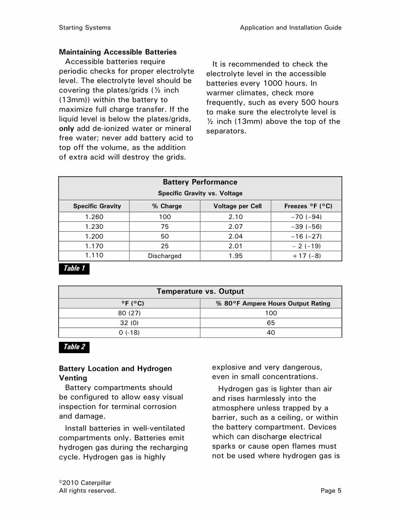
Maintaining Accessible Batteries
Accessible batteries require
periodic checks for proper electrolyte
level. The electrolyte level should be
covering the plates/grids (½ inch
(13mm)) within the battery to
maximize full charge transfer. If the
liquid level is below the plates/grids,
only add de-ionized water or mineral
free water; never add battery acid to
top off the volume, as the addition
of extra acid will destroy the grids.
It is recommended to check the
electrolyte level in the accessible
batteries every 1000 hours. In
warmer climates, check more
frequently, such as every 500 hours
to make sure the electrolyte level is
½ inch (13mm) above the top of the
separators.
Battery Performance
Specific Gravity vs. Voltage
Specific Gravity % Charge Voltage per Cell Freezes °F (°C)
1.260 100 2.10 –70 (–94)
1.230 75 2.07 –39 (–56)
1.200 50 2.04 –16 (–27)
1.170 25 2.01 – 2 (–19)
1.110 Discharged 1.95 +17 (–8)
Temperature vs. Output
°F (°C) % 80°F Ampere Hours Output Rating
80 (27) 100
32 (0) 65
0 (-18) 40
Battery Location and Hydrogen
Venting
Battery compartments should
be configured to allow easy visual
inspection for terminal corrosion
and damage.
Install batteries in well-ventilated
compartments only. Batteries emit
hydrogen gas during the recharging
cycle. Hydrogen gas is highly
explosive and very dangerous,
even in small concentrations.
Hydrogen gas is lighter than air
and rises harmlessly into the
atmosphere unless trapped by a
barrier, such as a ceiling, or within
the battery compartment. Devices
which can discharge electrical
sparks or cause open flames must
not be used where hydrogen gas is
Table 2
Table 1

Application and Installation Guide Starting Systems
©2010 Caterpillar
Page 6 All rights reserved.
likely to collect or in the path of
escaping hydrogen gas.
Battery Disconnect Switches
(Battery Isolating Devices)
Solid-state electrical devices can
be damaged by the use of battery
disconnect switches. These
switches often interrupt load
bearing circuits and at the instant
of a circuit disconnect, transient
currents and voltages can cause
failure in any component whose
transistors are not specifically
protected.
Note: Only use battery disconnect
switches that do not cause voltage
transients (spikes).
Transient suppressers are to be
used where applicable.
Suppressers absorb current surges
to prevent exposing these surges
to sensitive electronic systems.
Battery Chargers
Various chargers are available to
replenish a battery’s charge.
Trickle chargers are designed for
continuous service on unloaded
batteries and automatically step
down to milliampere current when
the batteries are fully charged.
Note: Overcharging shortens
battery life. Excessive water losses
may indicate overcharging.
Conventional lead-acid batteries
require less than 59.2 mL (2 oz)
of make-up water during each
30 hours of operation.
Float-equalize chargers are more
expensive than trickle chargers and
are used in applications demanding
maximum battery life. These
chargers include line and load
regulation, and current limiting
devices that permit continuous
loads at rated output.
Chargers must be capable of
limiting peak currents during
cranking cycles or have a relay to
disconnect during cranking cycles.
Where engine-driven alternators
and battery chargers are both
used, the disconnect relay is
usually controlled to disconnect
the battery charger during engine
cranking and running.
Engine-driven generators or
alternators can be used but have
the disadvantage of charging
batteries only while the engine
runs. Where generator sets are
subject to long idle periods or
many short stop-start cycles,
insufficient battery capacity could
threaten dependability.

Starting Systems Application and Installation Guide
©2010 Caterpillar
All rights reserved. Page 7
Optimum charging volts for 12-volt battery vs. temperature for lead acid
batteries, utilizing a charger.
*Use Caterpillar Data Sheet, PEHJ-0073 to identify chemical construction of Caterpillar
batteries to determine recommended charging voltages in previous table.
Charging Systems
Normally, engine-driven alternators
are used for battery charging. When
selecting an alternator, consideration
should be given to the current draw
of the electrical accessories to be
used and to the conditions in which
the alternator will be operating. An
alternator must be chosen that has
adequate capacity to power the
accessories and charge the battery.
If the alternator will be operating in a
dusty, dirty environment, a heavy-
duty alternator should be selected.
Consideration should also be given
to the speed at which the engine will
operate most of the time. An
alternator drive ratio should be
selected so that the alternator is
capable of charging the system over
the entire engine speed range.
Engine-driven alternators have the
disadvantage of charging batteries
only while the engine is running.
Trickle chargers are available but
require an A/C power source.
Battery chargers using AC power
sources must be capable of limiting
peak currents during the cranking
cycle or must have a relay to
disconnect the battery charger
during the cranking cycle. In
applications where an engine-driven
alternator and a battery trickle
charger are both used, the
disconnect relay must be controlled
to disconnect the trickle charger
during cranking and running periods
of the engine.
Temp
C
Temp
F
MF
CA/CA
MF
CA/CA
SB SB Low
SB
Hybrid
Low
SB
Hybrid
AGM AGM GEL GEL
Min
Volts
Max
Volts
Min
Volts
Max
Volts
Min
Volts
Max
Volts
Min
Volts
Max
Volts
Min
Volts
Max
Volts
80 176 12.90 14.70 12.60 13.20 12.60 13.80 12.90 13.50 12.80 12.90
60 140 12.94 14.74 12.64 13.24 12.64 13.84 12.90 13.54 12.80 12.94
40 104 13.32 15.12 13.02 13.62 13.02 14.22 13.02 13.92 13.02 13.32
20 68 13.80 15.60 13.50 14.10 13.50 14.70 13.50 14.40 13.50 13.80
0 32 14.46 16.26 14.16 14.76 14.16 15.36 14.16 15.06 14.16 14.46
-30 -22 15.90 17.70 15.60 16.20 15.60 16.80 15.60 16.50 15.60 15.90

Application and Installation Guide Starting Systems
©2010 Caterpillar
Page 8 All rights reserved.
Note: Marine and Petroleum engines
use separate ground starters and
alternators. See section for further
information.
Starter Motor
Continuous Cranking Time Limit with
Electric Starter Motors
To avoid overheating of the starter
motors, an engine should not be
cranked continuously for more than
30 seconds.
Starter Motor Cooling Period
Between Cranking Periods
Allow the starter motor to cool for
two minutes before resuming
cranking. If Marine Society certified,
refer to applicable documents for
cranking requirements.
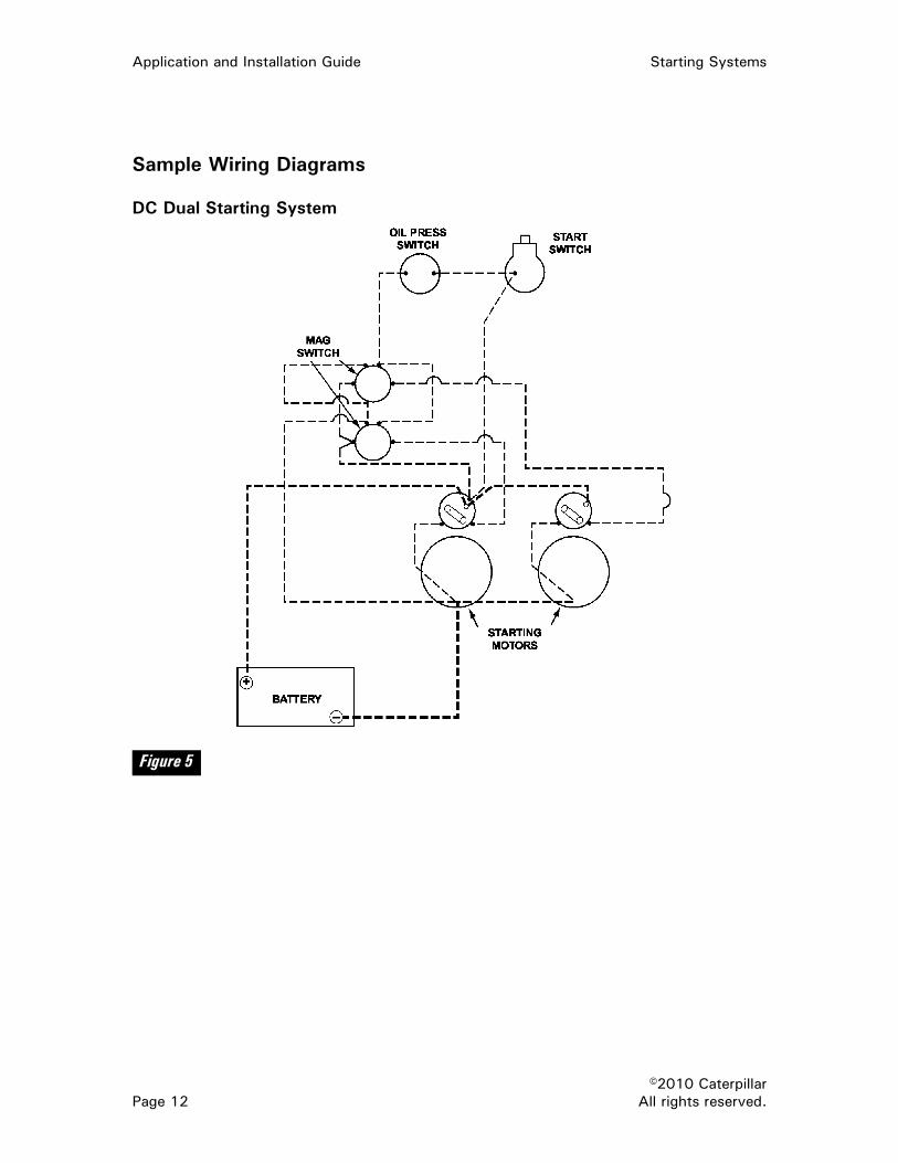
Starting System Wiring Power carrying capability and
serviceability are primary concerns
of the wiring system.
For correct size and correct circuit
for starting system components, see
wiring diagrams provided with the
engine or the Operation and
Maintenance manual. Sample
diagrams are shown at the end of
this section in Figure 5 and Figure 6.
All control wiring must be protected
by fuses or a manual reset circuit
breaker. The main battery cables
need not be fused. These may or
may not be shown on the wiring
diagrams. Fuses and circuit breakers
should have sufficient capacity and
be readily accessible for service.
Other preferred wiring practices
are:
• Use a minimum number of
connections, especially with
battery cables.
• Use positive mechanical
connections.
• Use permanently labeled or
color-coded wires.
• Position the batteries near the
starting motor; short cables
can be used to minimize
voltage drop.
• A ground cable from the
battery to starter is preferred
for all applications. This
ground cable is required for
all marine and many
petroleum applications.
• If frame connections are used,
tin the contact surface. The
path of the current must not
include high resistance points
such as painted, bolted, or
riveted joints.
• Protect the battery cables
from rubbing against sharp
or abrasive surfaces.
• All battery connections must
be kept tight and coated with
grease or other protectant to
prevent corrosion.
• The cranking batteries should
always be securely mounted
where it is easy to visually
inspect and maintain. They
must be located away from
flame or spark sources and
isolated from vibration.
Batteries should be mounted
level on non-conducting
material and protected from
splash and dirt. Short slack
pratik
Highlight
pratik
Highlight
pratik
Highlight

Starting Systems Application and Installation Guide
©2010 Caterpillar
All rights reserved. Page 9
cables should be used to
minimize voltage drops.
• Disconnect the battery
charger when removing or
connecting battery leads.
Solid-state equipment, like the
electronic governor or speed
switches, can be harmed if
subjected to transients.
• For 3600 applications with
electric starting, use separate
batteries for starting and
control systems, as shown in
Figure 5 at the end of this
section.
Battery Cable Sizing (Maximum
Allowable Resistance)
The start circuit between battery
and starting motor, and the control
circuit between the battery, battery-
switch, and motor solenoid must be
within maximum resistance limits
shown in Table 3.
Note: Resistance values in Table 3
include connections and contactors,
except the motor solenoid contactor.
Maximum Allowable Circuit Resistance
Magnetic Switch
and Series-
Parallel Circuit
Solenoid Switch
Circuit
Starting Motor
Circuit
12 Volt System
.048 Ohm .0067 Ohm .0012 Ohm
24 Volt System
.10 Ohm .030 Ohm .002 Ohm
32 Volt System
.124 Ohm .070 Ohm .002 Ohm
Fixed resistance allowances for
contactors, relays, solenoid and
switches are 0.0002 Ohm each.
Fixed resistance allowances for
connections (series connector) are
0.00001 Ohm each.
The fixed resistance of
connections and contactors is
determined by the cable routing.
Fixed resistance (Rf) subtracted from
total resistance (Rt) equals allowable
cable resistance (Rc).
Rt - Rf = Rc.
With cable length and fixed
resistance determined, select cable
size using Figure 3 and Table 4. Only
full-stranded copper wire should be
used. Arc welding cable is much
more flexible and easier to install
than full stranded copper wire cable,
but welding cable is not as durable
and will be damaged from corrosion
in a much shorter time. The ground
cable should also be added to the
circuit’s resistance calculations.
Figure 3
Table 3

Application and Installation Guide Starting Systems
©2010 Caterpillar
Page 10 All rights reserved.
Maximum Recommended Total Battery Cable Length
Cable Size Direct Electric Starting
12 Volt 24 – 32 Volt AWG MM2
Feet Meters Feet Meters
0 50 4.0 1.22 15.0 4.57
00 70 5.0 1.52 18.0 5.49
000 95 6.0 1.83 21.0 6.40
0000 120 7.5 2.29 27.0 8.24
To meet cable length and
resistance requirements, cable size
is most important. To determine
fixed resistance in a parallel circuit,
only the long cables of the parallel
circuit are counted. The paralleling
cables are short enough to be
insignificant in the resistance
calculation. In the parallel battery
connection shown in Figure 4, only
the 56-inch and the 76-inch cable
lengths need to be counted.
Connections/Proper Practices
Electrical connections are often
a source of problems in any
application. Shipboard, drill rig and
any other electrical system that is
exposed to salt air and water are
especially susceptible because
these elements are highly
corrosive. Electrical connections
are usually made of dissimilar
metals. Corrosion is more
destructive between dissimilar
metals.
The following items are good
practices for electrical system
connections.
• When making electrical
connections between wires,
connect wires mechanically
so tugging or pulling can be
withstood without any other
treatment of the joint.
• Coat the joint and the
nearest portions of each
wire with electrical solder.
• Do not expect solder to
increase joint strength.
The solder is for corrosion
protection.
Table 4
Figure 4
Starting Systems Application and Installation Guide
©2010 Caterpillar
All rights reserved. Page 11
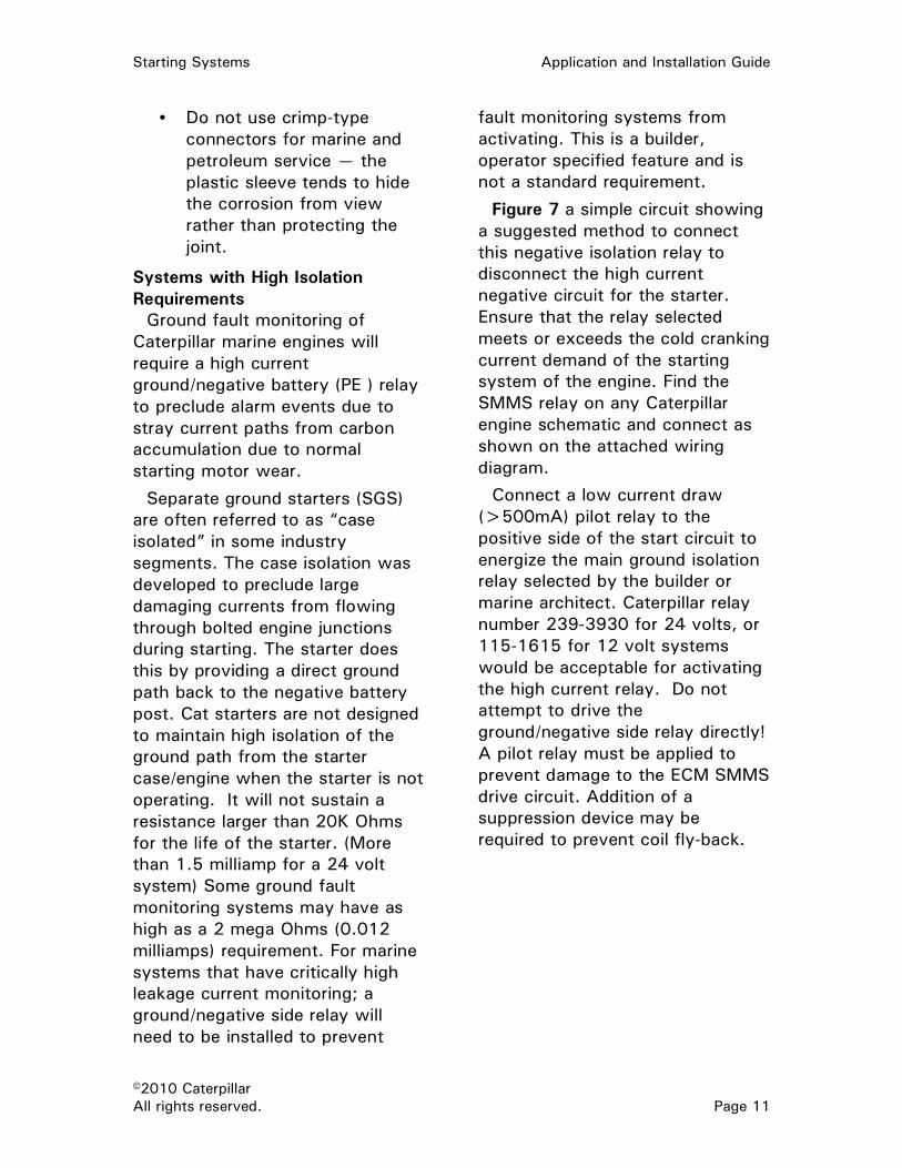
• Do not use crimp-type
connectors for marine and
petroleum service — the
plastic sleeve tends to hide
the corrosion from view
rather than protecting the
joint.
Systems with High Isolation
Requirements
Ground fault monitoring of
Caterpillar marine engines will
require a high current
ground/negative battery (PE ) relay
to preclude alarm events due to
stray current paths from carbon
accumulation due to normal
starting motor wear.
Separate ground starters (SGS)
are often referred to as “case
isolated” in some industry
segments. The case isolation was
developed to preclude large
damaging currents from flowing
through bolted engine junctions
during starting. The starter does
this by providing a direct ground
path back to the negative battery
post. Cat starters are not designed
to maintain high isolation of the
ground path from the starter
case/engine when the starter is not
operating. It will not sustain a
resistance larger than 20K Ohms
for the life of the starter. (More
than 1.5 milliamp for a 24 volt
system) Some ground fault
monitoring systems may have as
high as a 2 mega Ohms (0.012
milliamps) requirement. For marine
systems that have critically high
leakage current monitoring; a
ground/negative side relay will
need to be installed to prevent
fault monitoring systems from
activating. This is a builder,
operator specified feature and is
not a standard requirement.
Figure 7 a simple circuit showing
a suggested method to connect
this negative isolation relay to
disconnect the high current
negative circuit for the starter.
Ensure that the relay selected
meets or exceeds the cold cranking
current demand of the starting
system of the engine. Find the
SMMS relay on any Caterpillar
engine schematic and connect as
shown on the attached wiring
diagram.
Connect a low current draw
(>500mA) pilot relay to the
positive side of the start circuit to
energize the main ground isolation
relay selected by the builder or
marine architect. Caterpillar relay
number 239-3930 for 24 volts, or
115-1615 for 12 volt systems
would be acceptable for activating
the high current relay. Do not
attempt to drive the
ground/negative side relay directly!
A pilot relay must be applied to
prevent damage to the ECM SMMS
drive circuit. Addition of a
suppression device may be
required to prevent coil fly-back.
Application and Installation Guide Starting Systems
©2010 Caterpillar
Page 12 All rights reserved.
Sample Wiring Diagrams
DC Dual Starting System
Figure 5

Starting Systems Application and Installation Guide
©2010 Caterpillar
All rights reserved. Page 13
Typical Wiring Systems
Figure 6
Figure 7

Application and Installation Guide Starting Systems
©2010 Caterpillar
Page 14 All rights reserved.
Pneumatic Starting (Air)
Air starting, either manual or
automatic, is highly reliable. Torque
available from air motors accelerates
the engine to twice the cranking
speed in about half the time required
by electric starters.
Pneumatic starting is generally
applied to large engines in work-
boats, on land where facilities have
existing plant air, or where a
combustible gases may be present
in the atmosphere.
The air system can be quickly
recharged; but air storage tanks are
prone to condensation problems and
must be protected against internal
corrosion and freezing.
Typical Pneumatic Starter
Air is usually compressed to 758 to
1723 kPa (110 to 250 psi) and is
stored in storage tanks. Stored air is
regulated to from 620 kPa (90 psi) to
a maximum of 1550 kPa (225 psi)
depending on the engine and starter
and piped to the air motor. Consult
the Owners manual for the
recommended regulation pressure for
the engine model you are using. A
check valve between the compressor
and the air receiver is good practice,
to protect against a failure of plant
air that might deplete the air
receivers’ supply.
The air compressors that supply
pneumatic starters are driven by
external power sources such as
electric motors and diesel or gasoline
engines. A small emergency receiver
(not supplied by Caterpillar) can be
hand pumped to starting pressure
under emergency conditions. A more
common emergency backup will
include an auxiliary diesel engine-
driven air compressor package.
Air Tank Air tanks are required to meet
specific characteristics, such as the
specifications of the American
Society of Mechanical Engineers
(ASME). Compressed air storage
tanks must be equipped with a
maximum pressure valve and a
pressure gauge. Check the maximum
pressure valve and pressure gauge
often to confirm proper operation.
A drain cock must be provided in the
lowest part of the air receiver tank
for draining condensation.
Air Storage Tank Sizing
Many applications require sizing air
storage tanks to provide a specified
number of starts without recharging.
Figure 8
pratik
Highlight
pratik
Highlight
pratik
Highlight

Starting Systems Application and Installation Guide
©2010 Caterpillar
All rights reserved. Page 15
This is accomplished using the
following formula:
VS X T X PA VT = P1 - PMIN
Where:
VT = Air storage tank capacity
(cubic feet or cubic meters)
VS = Air consumption of the starter
motor (m3/sec or ft3/sec) —
Air Starting Requirements are in
the TMI for model engine used.
If prelube is used its consumption
must be added to VS also.
T = Total cranking time required
(seconds): If six consecutive
starts are required, use seven
seconds for first start (while
engine is cold), and two
seconds each for remaining
five starts, or a total cranking
time of seventeen seconds.
PA = Atmospheric pressure
(psi or kPa): Normally,
atmospheric pressure is
101 kPa (14.7 psi).
PT = Air storage tank pressure
(psi or kPa): This is the
storage tank pressure at
the start of cranking.
PMIN= Minimum air storage tank
pressure required to sustain
cranking at 100 rpm (psi
or kPa) — Air Starting
Requirements are in TMI for
model used.
Example:
A 3516 Diesel Engine with electric
prelube has the following:
Maximum air tank pressure =
1241 kPag (180 psig)
Minimum air to starter pressure =
620.5 kPag (90 psig)
Expected air line pressure drop =
207 kPag (30 psig)
Six consecutive starts. First start
= 7 seconds the other 5 starts =
2 seconds
Average barometric pressure at
this location = 100 kPa (14.5 psi)
Preconditioned engine installation.
(cfm x 0.02832 = m3/min)
Solution:
VS = 0.40 m3/sec (14.1 ft3/sec)
T = 7 + (5 x 2) = 17 sec
PA = 100 kPa (14.5 psi)
PT = 1241 – 207 = 1034 kPag
(180 – 30 = 150 psig)
PMIN= 620.5 kPag (90 psig)
Therefore:
0.4 X 17 X 100 VT= 1034 – 620.5
=1.64 m3
14.1 X 17 X 14.5 VT= 150 – 190
=57.93 ft3
Air Starting Motor
Cranking Time Required
The cranking time depends on
the engine model, engine condition,
ambient air temperature, oil
viscosity, fuel type, and design
cranking speed. Five to seven
seconds is typical for an engine
at 26.7°C (80°F). Restarting hot
pratik
Highlight

Application and Installation Guide Starting Systems
©2010 Caterpillar
Page 16 All rights reserved.
engines usually requires less than
two seconds. Most marine societies
require a minimum of six
consecutive starts for propulsion
engines. Refer to the applicable
marine society rules for current
requirements for propulsion and
other applications on marine vessels.
Note: Gas engines are generally a
little harder to start. Even during hot
starts, 10 second start attempts are
sometimes needed. See Operation
and Maintenance manual for starting
recommendations.
Note: Some gas engine applications
require purge cycles to vent
unburned fuel before the next start
attempt. Refer to local code or
industry recommended practice.
Air Consumption of the Starter
Motor
The starter motor air consumption
depends on the same variables as
mentioned in cranking time. The
air pressure regulator setting also
affects consumption. Normal
pressure regulator setting is 759 kPa
(110 psi). A higher pressure can be
used, up to a maximum of 1550 kPa
(225 psi), to improve starting under
adverse conditions. Specific
requirements for air starter
consumption on various engine
models are available from the TMI.
This data assumes a bare engine
(no parasitic load) at 10°C (50°F).
Operation
The supply of compressed air to
the starting motor must be shut off
as soon as the engine starts. This
will prevent wasting starting air
pressure and prevent damage to
starter motor by over-speeding.
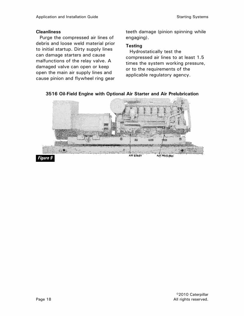
Prelubrication Systems
3600 Engines require prelubrication
for all other models check Operation
and Maintenance Manual. Figure 9
shows a 3516 oil-field engine with
an optional air starter and air
prelubrication system. The system
schematics in Figure 10, Figure 11
and Figure 12 show the included
prelubrication system on 3600
engines. The prelubrication system is
designed to provide lubricating oil to
critical components before cranking
and starting the engine.
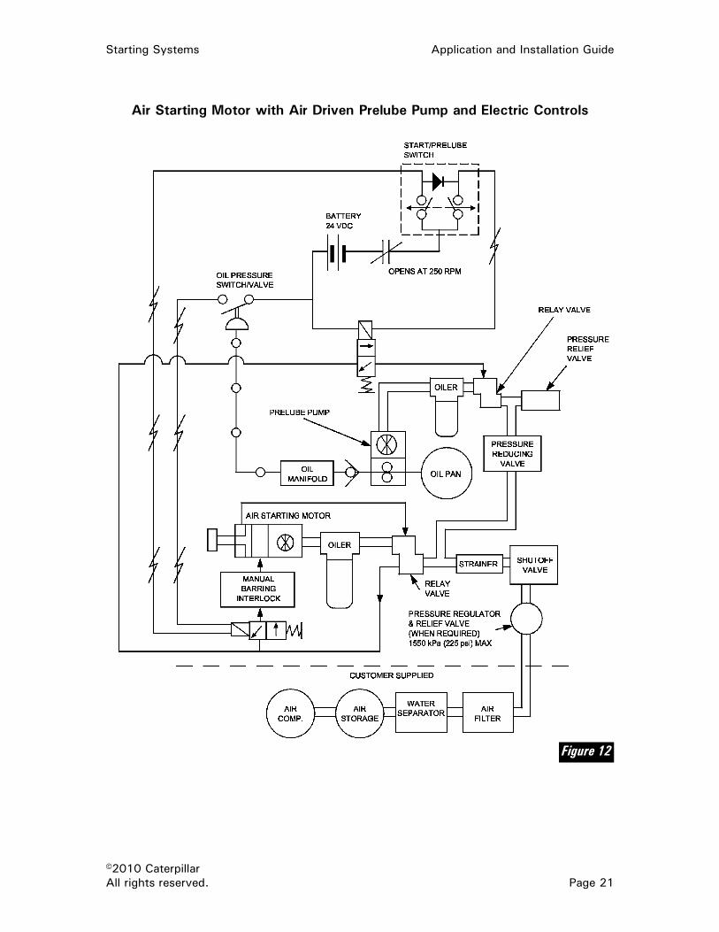
Caterpillar furnishes an air
cranking/air prelubricating system.
This consists of an air-driven
prelubrication pump that draws oil
from the engine sump and forces it
into the engine. This pump is driven
by an air motor, through sequence
valving runs, until a predetermined
engine oil pressure shuts it off and
turns on the air cranking motor.
The additional air consumed by the
prelube pump must be added to the
starter motor air consumption to
properly size the air receiver and air
storage tank needed.
Oil-field engine applications that
use the 2301A Electric Governor
do not require prelubrication pumps
because a properly wired 2301A
Governor maintains engine speed at
low idle speed until adequate oil
pressure is in the lube system. When
the engine starts and accelerates to
low idle, it will stay at that speed
until an electric switch is closed by
engine oil pressure. The engine will
then accelerate to rated speed.
pratik
Highlight
pratik
Highlight
pratik
Highlight
pratik
Highlight
pratik
Highlight
pratik
Highlight
pratik
Highlight

Starting Systems Application and Installation Guide
©2010 Caterpillar
All rights reserved. Page 17
Any solenoids used in the starting
system must be DC to ensure
starting during an AC power outage.
Piping Air starter air supply piping should
be short, direct and at least equal in
size to the motor intake opening.
Black iron pipe of seamless steel
ASTM-A106 grade is preferred to
prevent vibration induced fatigue
from the starter to the piping. The
piping requires flexible connections
at the starter. In some larger
engines, a flexible hose is included
from Caterpillar. Deposits of oil and
water will accumulate in the air
receiver and at low spots in the
piping. The accumulation of oil and
water must be removed daily to
prevent damage to the starting
motors. Manual or automatic traps
should be installed at the lowest
parts of the piping and all piping
should slope toward these traps.
If the engine operates at ambient
air temperature below 0°C (32°F),
and operates in a high humidity
environment, an air dryer is needed
to prevent condensed water from
freezing in piping. When the same
air is used for other purposes, e.g.,
engine controls, the air dryer is
essential. A small quantity of alcohol
in the starter air tank also prevents
freezing if a dryer is not used. At
temperatures below –18°C (0°F)
consult the supplier.
During starting, an air pressure
drop is associated with each air
supply component. These
components include the lubricator,
strainer, relay valves and others.
Note: Vane-type air starters may
also freeze during high humidity
and low temperatures. Applications
equipped with turbine-type air
starters may also freeze in some
low ambient conditions, but are less
susceptible to motor freeze than
vane-type air starters.
Dynamic losses range from 207
to 414 kPa (30 to 60 psi) depending
on the engine model and supply line
pressure. A minimum 759 kPa
(110 psi) supply pressure is
recommended for proper operation
of the starting motors.
Starter/prelube supply and exhaust
piping practice is critical when
installing the engine. If restricted
in excess the starter motor
performance will be negatively
impacted. Proper pipe diameter,
length and directional changes such
as elbows, tees and the like, all
must be accounted for in the piping
design. As with any site piping,
industry standards and regulations
for each application come into play
and will define the appropriate piping
material and safeguards necessary
for the application. Combustible gas
exhausting from starter motors must
be piped away to designated area or
to the atmosphere especially in gas
service applications.
Hazardous locations will require
CSA rating and regulations for
starter/prelube attachment solenoid
valves for control switching.
Blocking valves that positively
disconnect the main air/gas supply
when the starting/prelube cycles are
completed may be necessary in
come applications.
pratik
Highlight
pratik
Highlight
pratik
Highlight
pratik
Highlight
Application and Installation Guide Starting Systems
©2010 Caterpillar
Page 18 All rights reserved.
Cleanliness
Purge the compressed air lines of
debris and loose weld material prior
to initial startup. Dirty supply lines
can damage starters and cause
malfunctions of the relay valve. A
damaged valve can open or keep
open the main air supply lines and
cause pinion and flywheel ring gear
teeth damage (pinion spinning while
engaging).
Testing
Hydrostatically test the
compressed air lines to at least 1.5
times the system working pressure,
or to the requirements of the
applicable regulatory agency.
3516 Oil-Field Engine with Optional Air Starter and Air Prelubrication
Figure 9

Starting Systems Application and Installation Guide
©2010 Caterpillar
All rights reserved. Page 19
Typical Air Starting System
Figure 10

Application and Installation Guide Starting Systems
©2010 Caterpillar
Page 20 All rights reserved.
Air Starting Motor with Electric Prelube Pump and Electric Controls
Figure 11
Starting Systems Application and Installation Guide
©2010 Caterpillar
All rights reserved. Page 21
Air Starting Motor with Air Driven Prelube Pump and Electric Controls
Figure 12

Application and Installation Guide Starting Systems
©2010 Caterpillar
Page 22 All rights reserved.
Hydraulic Starting
Hydraulic starting provides high
cranking speeds fast starts, and is
relatively compact. Recharging time,
using the small engine-driven
recharging pump, is fast.
Hydraulic systems can be
recharged using a special hand
pump, but process is very laborious.
The high pressure of the system
requires special pipes and fittings
and extremely tight connections.
Oil lost through leakage can easily
be replaced, but because of high
pressures in the accumulators,
usually 20,700 kPa (3000 psi) when
fully charged, recharging the
accumulator(s) requires special
equipment.
Hydraulic System
Considerations • Repair to the system usually
requires special tools.
• Hydraulic starting is most
often used where the use of
electrical connections could
pose a safety hazard.
• Hydraulic starting systems are
not available from Caterpillar
for most models. They are
available for 3508 and 3512
engines. Contact your local
Cat dealer for the nearest
available supplier of other
models.
• If hydraulic accumulators are
used, they must be very
carefully protected from
perforation or breakage.
Hydraulic accumulators
contain large amounts of
stored mechanical energy.

Starting Systems Application and Installation Guide
©2010 Caterpillar
All rights reserved. Page 23
Starting Aids
Diesel engines require the heat of
compressed air in the cylinder to
ignite the fuel. Below certain
temperatures, the cranking system
will not crank the engine fast
enough or long enough to ignite the
fuel. One or more commonly used
starting aids, such as jacket water
heaters and/or ether may be required
to start the engine. In addition,
engines with prelube requirements
may require oil heaters. Refer to
Operation and Maintenance manual
for the engine model selected for
cold weather procedures.
Jacket Water Heaters
Jacket water heaters are electrical
heaters that maintain the jacket
water at a temperature high enough
to allow easy starting of the engine.
More heaters of higher ratings may
be required in areas of extremely
cold temperature.
Jacket water heaters are used on
both manual and automatic starting
systems, but are essential for
automatic starting below 21°C
(70°F). Heaters precondition engines
for quick starting and minimize the
high wear of rough combustion, by
maintaining jacket water
temperature during shutdown
periods.
Heaters thermostatically control
jacket water temperature near 30°C
(90°F) to promote fast starts. Higher
temperatures accelerate aging of
gaskets and rubber material.
Battery Heaters
Battery heaters are usually
recommended in cold ambient
temperatures. The heaters should be
set to maintain battery temperature
in the range of 32 to 52°C (90 to
125°F) for maximum effectiveness.
Ether
Ether is a volatile and highly
combustible agent. Small quantities
of ether fumes added to the engine’s
intake air during cranking reduce
compression temperature required
for engine starting. This method can
be used for starting of an engine at
practically any ambient temperature.
Ether starting aids are available on
the smaller Cat engines.
CAUTION: When other than fully
sealed ether systems are used,
ensure adequate ventilation for
venting fumes to the atmosphere to
prevent accidental explosion and
danger to operating personnel.
The high-pressure metallic capsule-
type is recommended for mobile
applications. When placed in an
injection device and pierced, ether
passes into the intake manifold. This
has proven to be the best system
since few special precautions are
required for handling, shipping, or
storage.
Ether must be used only as
directed by the manufacturer of the
starting aid device. The ether system
must be such that a maximum of
3.0 cc (0.18 cu in) of ether will be
released each time the button is
pushed. Caterpillar ether systems
are designed to release 2.25 cc
(0.14 cu in) of ether each time the
system is activated. Excessive
injection of ether can damage an

Application and Installation Guide Starting Systems
©2010 Caterpillar
Page 24 All rights reserved.
engine. Ether should not be released
into a running engine.
Lighter fuels, such as kerosene,
can ease the unaided cranking
requirements slightly by lowering the
compression temperature required
for starting. These lighter fuels also
slightly reduce horsepower delivered
at any given fuel rack setting.
Excessive parasitic loads should be
disconnected during engine cranking.
CAUTION: Under no circumstances
should ether be used on any 3600
model engines or any engine that
has an air inlet heater. Warning
labels may be necessary if remote
air intakes are used and the engine
has an inlet heater. Labeling when
remote air inlets are used is the
responsibility of the customer or
end user.
Manifold Heaters
Heat added to the intake manifold
of an engine during cranking will
significantly improve startability and
reduce any white start-up smoke.
Manifold heaters are used on small
engines available from Caterpillar.
Caterpillar does not offer manifold
heaters on larger marine engines.
Starting Smoke High performance engines are
prone to have some white start-up
smoke. The white smoke is
composed of unburned fuel. Cat
engines have been designed to
minimize this problem. Electronically
controlled engines have a cold mode
strategy built into the software to
reduce start-up smoke.
Operators can do several things to
improve the situation:
• Use jacket water heaters
to raise the engine water
temperature to 32 to 49°C
(90 to 120°F) prior to
starting.
• Keep warm-up idle speeds
(rpm) low.
• Warm the air to the air
cleaners and intake manifold.
• Diesel engines that are
designed to have high output
power, yet still be relatively
lightweight, generally have
low compression ratios; i.e.,
in the range of 12.5 to 16:1.
This design factor makes
them prone to misfire and run
rough until the engine reaches
normal operating jacket water
temperatures of 80 to 93°C
(175 to 200°F).
Driven Load Reduction Devices
Effect of driven equipment loads
during cold weather engine starting
must be considered. Hydraulic
pumps, air compressors, and other
mechanically driven devices typically
demand more horsepower when
they are extremely cold at start-up.
The effect of this horsepower
demand may be overcome by
providing a means of declutching
driven loads until the engine has
been started and warmed up for a
few minutes. This is not always
easy or practical, so other means
of relieving the load at cold start-up
may be required if the engine-load
combination cannot be started with
sufficient ease using the engine
starting aids described earlier.
Starting Systems Application and Installation Guide
©2010 Caterpillar
All rights reserved. Page 25
Some engine driven air
compressors provide for shutoff of
the air compressor air inlet during
cold starting. This greatly decreases
drag on the engine and improves
cold startability. This approach can
only be used when the air
compressor manufacturer provides
this system and fully approves of its
use. Air compressor damage could
result.

Application and Installation Guide Starting Systems
©2010 Caterpillar
Page 26 All rights reserved.
Emergency & Fast Starting
Some emergency and standby
power applications require the
ability for fast starting. Certain
engine configurations are capable of
supporting emergency power supply
systems such that loads can be
accepted within 10 seconds of a
power outage.
The following list offers
recommendations to achieve faster
starting.
Note: If a project has a start time
requirement, it is highly
recommended that a Start Time
Analysis (STA) is completed for the
overall system. The STA provides a
systems analysis on the basis of
detailed input relating to the site
conditions, intended electrical
system components and the overall
design of the critical power path. A
factory supported start time analysis
will be available only for C175,
through the ASC inquiry system.
Note: The parameters listed below
will improve starting but cannot
guarantee starting in a certain
number of seconds. Contact your
Cat dealer if a specific fast start
time is required for your application.
• Maintain jacket water
temperature at 49° C
(120 ° F).
• Combustion air requirement of
21C minimum.
• Use dual jacket water heaters,
if not circulating type or
redundant.
• Starter must be able to crank
engine above 110 rpm for ten
seconds.
• Use dual heavy duty electric
starters.
• Fully charged batteries.
• Heated batteries, if ambient
temperatures are below 0°C.
• Depending on engine model,
air starters may increase or
decrease cranking speeds and
thus affect the overall start
time. Please consult your Cat
dealer for starter
recommendations for your
package.
• Use backup battery charger.
• Optional air starter.
• Air pressure adequate to
crank engine above 110 rpm.
• Air tank and line volume large
enough to crank engine above
engine starting RPM.
• Set purge cycle time to zero
for EMCPII engines.
• Continuous engine oil
prelubrication must be
installed and operating, if
available on engine model.
• Fuel pressure must be up to
the engine shutoff valve.
• The engine fuel shutoff must
be installed as close the
engine regulator as possible.
• The fuel shutoff valve must
be energized at the same time
as the starters.

Starting Systems Application and Installation Guide
©2010 Caterpillar
All rights reserved. Page 27
• High-pressure gas systems
will reach high idle faster than
low-pressure gas systems.
• Low-pressure systems are
more stable at high idle.
• Spark plugs and transformers
must be properly maintained
and operational.
• Oversized and high voltage
generators increase the
rotational inertia of the
package and will slow start
times.
• Engine driven radiator fans
will slow package start times.
Using oversized or high
voltage generators in
conjunction with engine driven
fans may increase start times
such that a 10 second start
will not be achievable. If using
an oversized or high voltage
generator, consider using a
remote radiator with electric
driven fans.

Application and Installation Guide Starting Systems
©2010 Caterpillar
Page 28 All rights reserved.

.

LEBW4980-05 ©2010 Caterpillar Printed in U.S.A.
All rights reserved.
Related Documents