Starting Of A Motor and its Effect on System Voltage Siddhartha Porwal 12/19/2013 The objective of this report is to present the transient effects of motor starting on the sys- tem voltage. Electric motors are one of the most common items of electrical equipment in service. Despite the usefulness of electric motors, there are issues in starting motors - One of the most common side effects of starting large motors is a serious voltage dip on the buses throughout the facility. Particular concern is the growth of magnetic fields and back emf during starting leading to large currents and torque during this period. These currents and torque can have negative effects on both the electrical system and mechanical load. A motor starting study is performed to determine the voltages, currents, and starting times involved when starting large motors. Such a study is therefore critical before installing a large motor to make certain that the system can start the motor successfully. It may also be performed anytime a change in the power supply is implemented. Usually only the larg- est motor on a bus or system is modeled, but the calculation can in principle be used for any motor. It's important to note that motor starting is a transient power flow problem and is normally done iteratively by computer software. However, a static method is shown here for first-pass estimates only. The information was gathered from a number of journals and research articles as well as several motor manufacturers’ informational websites. From the sources reviewed I ultimately arrived at the conclusion that the above study can help select the best method of starting, the proper motor design, or the required system design for minimizing the impact of motor starting on the entire system. Siddhartha Porwal

Starting Of A Motor & Its Effects on System
Oct 22, 2015
Starting Of A Motor & Its Effects on System
Various Methods to Start Motor Without Effecting the system of transient currents.
Various Methods to Start Motor Without Effecting the system of transient currents.
Welcome message from author
This document is posted to help you gain knowledge. Please leave a comment to let me know what you think about it! Share it to your friends and learn new things together.
Transcript

Starting Of A Motor and its Effect on System Voltage
Siddhartha Porwal
12/19/2013
The objective of this report is to present the transient effects of motor starting on the sys-tem voltage. Electric motors are one of the most common items of electrical equipment in service. Despite the usefulness of electric motors, there are issues in starting motors - One of the most common side effects of starting large motors is a serious voltage dip on the buses throughout the facility. Particular concern is the growth of magnetic fields and back emf during starting leading to large currents and torque during this period. These currents and torque can have negative effects on both the electrical system and mechanical load. A motor starting study is performed to determine the voltages, currents, and starting times involved when starting large motors. Such a study is therefore critical before installing a large motor to make certain that the system can start the motor successfully. It may also be performed anytime a change in the power supply is implemented. Usually only the larg-est motor on a bus or system is modeled, but the calculation can in principle be used for any motor. It's important to note that motor starting is a transient power flow problem and is normally done iteratively by computer software. However, a static method is shown here for first-pass estimates only. The information was gathered from a number of journals and research articles as well as several motor manufacturers’ informational websites. From the sources reviewed I ultimately arrived at the conclusion that the above study can help select the best method of starting, the proper motor design, or the required system design for minimizing the impact of motor starting on the entire system.
Siddha
rtha P
orwal

2
TableofContents
Coverpage 1
Abstract 1
TableofContents 2
Introduction 3
Principle 4
DesignandProcedure
Methods 4
Discussion 5
MotorStartingAnalysisStudy 5
MotorController:‐Application&Types 6
OverloadRelays 8
MotorStartingTimeCalculation 9
WorkedExample 10
CalculatingtheTransientEffectsofmotorstartingontheSystemVoltages 11
WorkedExample 19
Conclusions 24
References 25
AppendixA‐1 26
Siddha
rtha P
orwal

3
Introduction :‐
Electric motors are one of the most common pieces of electrical equipment in service. From toys and
household appliances to the largest machines on the planet electric motors are used. Motors as the sin‐
gle biggest electricity users are estimated to account for between 43 and 46% of total global electricity.
For over a hundred years, we have been using motors and during that time there has been relatively
little change in how they function. Of all motor types, the induction motor is by far the most widely
used in industrial and building applications. Within this article, I'll primarily be concentrating on the ap‐
plication of motor starting in connection with induction motors.
Induction motors convert electrical power into rotating power and rely on the interaction of magnetic
fields to achieve this. Motor starting is the period of time from when the electrical supply is connected
to the motor until the motor accelerates to full speed. During this time, the buildup of magnetic fields
and back e.m.f introduce transient conditions on the electrical system. These transient events can affect
the electrical supply system and other equipment connected to it. Limiting the transient effects and
ensuring that motors accelerate the mechanical load correctly are the key reasons consideration is given
to motor starting.
Figure 1: http://myelectrical.com/Portals/0/SunBlogNuke/2/WindowsLiveWriter/MotorStartingIntroduction_BC07/Motor%20Staring%20Current_2.jpgSidd
harth
a Porw
al

4
Principle:‐
During the starting period the magnetic fields within the motor and back emf are increasing; the me‐
chanical load is accelerating and a current significantly larger than the motors normal full load running
current is drawn. This start‐up current can be as high as five to eight times the full load current.
Duration of the starting period is dependent on the combination of the motor and mechanical load and
can be anything from a fraction of a second to thirty seconds or longer. During the start‐up period, the
high levels of current required can have detrimental effects on the electrical supply system and other
connected equipment.
Design and Procedures
During the design of any electrical system, consideration is given to the ensuring that the steady state
running period conditions are adequately catered for. Cables are sized for this and voltage drops across
the electrical system calculated on this basis. During starting however, cables are going to be carrying
more current and the system voltage drops will become much larger. This is particularly apparent if
large motors are started and/or many motors are started at the same time. Voltage drops within an
electrical system may affect other equipment; even to the extent of causing failures. In addition, if the
voltage drop to the motor itself is too great, the motor may be unable to develop sufficient torque to
accelerate the mechanical load.
Overcoming these problems has been a concern of engineers since motors first started to achieve wide‐
spread adoption. Over the years, many methods and techniques have been developed to address these
issues; each with its own advantages and limitations. Recent decades have seen massive strides in the
utilization of electronics in providing electrical power to motors; which not only enable a great deal of
control over the starting current, but can allow the motor to operate with very specific acceleration
characteristics.
Methods:‐
Subsequent posts will look at some of the more commonly used methods of motor starting, which try to
address the problems of starting current and torque, each of which has its own advantages and disad‐
vantages:
1.) Direct On Line ‐ is the simplest and most cost effective, with the motor simply connected to the
supply. This method of starting suffers from high current/torque during starting. Due to its sim‐
plicity it is my preferred method of starting; however, there are many instances where it’s dis‐
advantages make it impractical.
2.) Star Delta ‐ is a reduced voltage starting method whereby the stator windings are initially con‐
nected in a star configuration and then switched to delta when the motor has accelerated. In
star, the voltage across each winding is reduced by a factor of √3 resul ng in a lower star ng
current and a starting torque of approximately 33% the full voltage torque.
Siddha
rtha P
orwal

5
3.) Auto‐Transformer ‐ is another reduced voltage method, whereby an auto‐transformer provides
the starting voltage. Using an auto‐transformer allows the level of voltage (consequently cur‐
rent and torque) to one of a wide range of value. With tapped auto‐transformers, it is also pos‐
sible to vary the starting characteristics during the run‐up period.
4.) Primary Resistance ‐ in this method one or more banks of resistors are inserted into the stator
winding during starting. Voltage drop across the resistors result in a reduced voltage at the mo‐
tor terminals and improved starting characteristics. As the motor current decreases (and volt‐
age drop across the resistors), voltage on the winding increases resulting in a fast increase in
torque during starting.
5.) Rotor Resistance ‐ like primary resistance, starting is controlled by the introduction of resistance
banks, however, in the rotor (not stator). During rotor resistance starting, the torque is approx‐
imately proportional to the motor current. Selection of the resistor banks can achieve a close
match to the required mechanical characteristics during starting.
6.) Electronic Soft Start ‐ in which back to back thyristors are switched to ramp up the voltage dur‐
ing starting (or ramp down during stopping). Selection of different ramp characteristics, initial
starting voltage and current limiting functions allow soft starters to match the requirements of
the mechanical load, provide smooth acceleration and ensure that reasonable values of starting
current are drawn from the supply.
For detailed comparison kindly check the comparison table in Appendix A1 at the end. The table A1
summarizes the characteristics, advantages and disadvantages of various starting methods.
Discussion
Motor Starting Analysis Study :‐
A motor starting study is performed to determine the voltages, currents, and starting times involved
when starting large motors. Such a study is critical before installing a large motor to make certain that
your system can start the motor successfully. It may also be performed anytime a change in the power
supply is implemented.
Starting large motors can cause disturbances to the motor and other loads on other buses. In the worst
cases the starting motor may stall and be unable to start the driven load. In general, a motor starting
study should be made if the motor’s horsepower exceeds approximately 30% of the supply transformers
base kVA rating. If a generator is supplying the motor, use 10 –15% of the generator kVA rating. Motor
starting studies can vary from basic voltage drop on the system to a detailed waveform presentation of
motor bus voltage, motor speed and motor torque, acceleration torque, load torque, power factor, ro‐
tor and stator currents, motor slip, real, reactive and total power.
One of the most common side effects of starting large motors is a serious voltage dip on the buses
throughout the facility. This voltage dip will cause other motors to slow down, in severe cases other mo‐
tors may reach the stall point causing a domino effect to the voltage drop. Control relays may not hold
Siddha
rtha P
orwal

6
and auxiliary equipment may be affected. In addition to these secondary effects the life of all motors on
the system may be shortened. Ideally a transient motor starting study should be preformed which
shows a time/voltage waveform for the motor bus. Motor starting studies should be performed prior to
the ordering of large motors, such that the motor can be installed with confidence that the motor’s life
and applications performance will be satisfactory and the remainder of the power distribution system
will not be adversely affected.
By using motor‐starting study techniques, these problems can be predicted before the installation of the
motor. It may also be performed anytime a change in the power supply is implemented. If a starting de‐
vice is needed, its characteristics and ratings can be easily determined. Also, voltage at important loca‐
tions throughout the system during start‐up can be monitored. The study can help select the best meth‐
od of starting, the proper motor design, or the required system design for minimizing the impact of mo‐
tor starting on the entire system.
Motor controller :‐
A motor controller is a device or group of devices that serves to govern in some predetermined manner
the performance of an electric motor. A motor controller might include a manual or automatic means
for starting and stopping the motor, selecting forward or reverse rotation, selecting and regulating the
speed, regulating or limiting the torque, and protecting against overloads and faults
Application of Motor Controller :‐
Every electric motor has to have some sort of controller. The motor controller will have differing fea‐
tures and complexity depending on the task that the motor will be performing.
The simplest case is a switch to connect a motor to a power source, such as in small appliances or power
tools. The switch may be manually operated or may be a relay or contactor connected to some form of
sensor to automatically start and stop the motor. The switch may have several positions to select differ‐
ent connections of the motor. This may allow reduced‐voltage starting of the motor, reversing control or
selection of multiple speeds. Overload and over current protection may be omitted in very small motor
controllers, which rely on the supplying circuit to have over current protection. Small motors may have
built‐in overload devices to automatically open the circuit on overload. Larger motors have a protective
overload relay or temperature sensing relay included in the controller and fuses or circuit breakers for
over current protection. An automatic motor controller may also include limit switches or other devices
to protect the driven machinery.
More complex motor controllers may be used to accurately control the speed and torque of the con‐
nected motor (or motors) and may be part of closed loop control systems for precise positioning of a
driven machine. For example, a numerically controlled lathe will accurately position the cutting tool ac‐
cording to a preprogrammed profile and compensate for varying load conditions and perturbing forces
to maintain tool position.
Siddha
rtha P
orwal

7
Types of motor controllers :‐
Motor controllers can be manually, remotely or automatically operated. They may include only the
means for starting and stopping the motor or they may include other functions. An electric motor con‐
troller can be classified by the type of motor it is to drive such as permanent magnet, servo, series, sepa‐
rately excited, and alternating current. A motor controller is connected to a power source such as a bat‐
tery pack or power supply, and control circuitry in the form of analog or digital input signals.
Motor starters
A small motor can be started by simply plugging it into an electrical receptacle or by using a switch or
circuit breaker. A larger motor requires a specialized switching unit called a motor starter or motor con‐
tactor. When energized, a direct on line (DOL) starter immediately connects the motor terminals directly
to the power supply. Reduced‐voltage, star‐delta or soft starters connects the motor to the power sup‐
ply through a voltage reduction device and increases the applied voltage gradually or in steps. In smaller
sizes a motor starter is a manually operated switch; larger motors, or those requiring remote or auto‐
matic control, use magnetic contactors. Very large motors running on medium voltage power supplies
(thousands of volts) may use power circuit breakers as switching elements. A direct on line starter can
be used if the high inrush current of the motor does not cause excessive voltage drop in the supply cir‐
cuit.
A reversing starter can connect the motor for rotation in either direction. Such a starter contains two
DOL circuits—one for clockwise operation and the other for counter‐clockwise operation, with mechani‐
cal and electrical interlocks to prevent simultaneous closure. For three phase motors, this is achieved by
transposing any two phases. Single phase AC motors and direct‐current motors require additional devic‐
es for reversing rotation.
Reduced voltage starters
Two or more contactors may be used to provide reduced voltage starting of a motor. By using an auto‐
transformer or a series inductance, a lower voltage is present at the motor terminals, reducing starting
torque and inrush current. Once the motor has come up to some fraction of its full‐load speed, the
starter switches to full voltage at the motor terminals. Since the autotransformer or series reactor only
carries the heavy motor starting current for a few seconds, the devices can be much smaller compared
to continuously rated equipment. The transition between reduced and full voltage may be based on
elapsed time, or triggered when a current sensor shows the motor current has begun to reduce.
Adjustable‐speed drives
An adjustable‐speed drive (ASD) or variable‐speed drive (VSD) is an interconnected combination of
equipment that provides a means of driving and adjusting the operating speed of a mechanical load. An
electrical adjustable‐speed drive consists of an electric motor and a speed controller or power converter
plus auxiliary devices and equipment. In common usage, the term “drive” is often applied to just the
controller
Siddha
rtha P
orwal

8
Intelligent controllers :‐
An Intelligent Motor Controller (IMC) uses a microprocessor to control power electronic devices used for
motor control. IMCs monitor the load on a motor and accordingly match motor torque to motor load.
This is accomplished by reducing the voltage to the AC terminals and at the same time lowering current
and kvar. This can provide a measure of energy efficiency improvement for motors that run under light
load for a large part of the time, resulting in less heat, noise, and vibrations generated by the motor.
Overload Relays :‐
A starter will contain protective devices for the motor. At a minimum this would include a thermal over‐
load relay. The thermal overload is designed to open the starting circuit and thus cut the power to the
motor in the event of the motor drawing too much current from the supply for an extended time. The
overload relay has a normally closed contact which opens due to heat generated by excessive current
flowing through the circuit. Thermal overloads have a small heating device that increases in temperature
as the motor running current increases.
There are two types of thermal overload relay :‐
In one type, a bi‐metallic strip located close to a heater deflects as the heater temperature rises until it
mechanically causes the device to trip and open the circuit, cutting power to the motor should it be‐
come overloaded.
A second type of thermal overload relay uses a eutectic alloy, like a solder, to retain a spring‐loaded con‐
tact. When too much current passes through the heating element for too long a time, the alloy melts
and the spring releases the contact, opening the control circuit and shutting down the motor.
Motor Starting Time ‐ it's a little complicated
The first thing to look at in the previous Graph G1 is the motor characteristic. The image shows a typical
motor torque curve and a hypothetical load torque curve superimposed. The torque available to accel‐
erate the motor up to speed is given by the difference between motor torque and load torque:
Graph G1 :‐ Motor
Speed Vs. Torque
Link :‐
http://myelectrical.
com/notes/entryid/
107/how‐to‐
calculate‐motor‐
starting‐time Siddha
rtha P
orwal

9
C(a) = C(M) – C(L)
Where, C(a) ‐ torque to accelerate the motor, N.m
C(M) – motor torque, N.m & C(L) – load torque, N.m
As can be seen, as the speed increases both the motor and load torque vary. The motor torque charac‐
teristic is also a function of the design and construction of the motor and can vary significantly for mo‐
tors of the same rating. Starting methods also affect the available motor torque and can even affect the
shape of the curve.
Any torque used for acceleration, needs to overcome both the inertia of the motor and the load. By
using this and knowing a bit of mechanical engineering (Reference No. #), it is possible to derive an
equation for the time to accelerate from zero to the running speed:
Where:
ta – time to accelerate to running speed, s nr – motor running speed, rpm CM – motor torque, N.m CL – load torque, N.m JM – inertia of the motor, kg.m2 JL – inertia of the load, kg.m2
Starting Time ‐ an easier [rough] approximation
By introducing some simplifications, it is possible to have an easier to use formulae to give an approxi‐
mation for the starting time. The first simplification is to use an average value of motor torque,
Where Cs ‐ the inrush torque, N.m Cmax ‐ the maximum torque, N.m Both these figures are available from the manufacturer.
For reduced voltages, torque is reduced by the square of the reduction, so It should be possible to adjust
the average torque for reduced voltage starting (i.e. star‐delta).
The second simplification is to use an adjustment factor KL to take care of varying load torque CL due to
speed changes:
Siddha
rtha P
orwal

10
Type of Load
Load Factor, KL Lift Fans Piston Pumps Flywheel
1 0.33 0.5 0
Using the simplifications, the approximate starting time is given by: ‐
Where Cacc is the effective acceleration torque and is given by
An example will show how this works:
A 90 kW motor is used to drive a fan. From the motor manufacturer and mechanical engineer we have:
Motor Rated Speed (nr) ‐ 1500 rpm Motor Full Load Speed ‐ 1486 rpm Motor Inertial (JM) ‐ 1.4 kg.m2 Motor Rated Torque ‐ 549 Nm Motor Inrush Torque (CS) ‐ 1563 Nm Motor Maximum Torque (Cmax) ‐ 1679 Nm Load Inertia (JL) ‐ 30 kg.m2 Load Torque (CL) ‐ 620 Nm Load Factor (KL) ‐ 0.33
Siddha
rtha P
orwal

11
Calculating the Transient Effects of motor starting on the System Voltages
This article considers the transient effects of motor starting on the system voltage. Usually only the larg‐
est motor on a bus or system modeled, but the calculation can in principle be used for any motor. It's
important to note that motor starting is a transient power flow problem and is normally done iteratively
by computer software. However a static method is shown here for first‐pass estimates only.
Why do the calculation?
When a motor is started, it typically draws a current 6‐7 times its full load current for a short duration
(commonly called the locked rotor current). During this transient period, the source impedance is gen‐
erally assumed to be fixed and therefore, a large increase in current will result in a larger voltage drop
across the source impedance. This means that there can be large momentary voltage drops system‐
wide, from the power source (e.g. transformer or generator) through the intermediary buses, all the
way to the motor terminals.
A system‐wide voltage drop can have a number of adverse effects, for example: Equipment with minimum voltage tolerances (e.g. electronics) may malfunction or behave aber‐
rantly Under voltage protection may be tripped The motor itself may not start as torque is proportional to the square of the stator voltage, so a
reduced voltage equals lower torque. Induction motors are typically designed to start with a terminal voltage >80%
When to do the calculation?
This calculation is more or less done to verify that the largest motor does not cause system wide prob‐lems upon starting. Therefore it should be done after preliminary system design is complete. The follow‐ing prerequisite information is required:
Key single line diagrams Preliminary load schedule Tolerable voltage drop limits during motor starting, which are typically prescribed by the client
Calculation Methodology
This calculation is based on standard impedance formulae and Ohm's law. To the author's knowledge,
there are no international standards that govern voltage drop calculations during motor start.
It should be noted that the proposed method is not 100% accurate because it is a static calculation. In
reality, the voltage levels are fluctuating during a transient condition, and therefore so are the load cur‐
rents drawn by the standing loads. This makes it essentially a load flow problem and a more precise so‐
lution would solve the load flow problem iteratively, for example using the Newton‐Rhapson or Gauss‐
Siedel algorithms. Notwithstanding, the proposed method is suitably accurate for a first pass solution.
Siddha
rtha P
orwal

12
The calculation has the following six general steps:
Step 1: Construct the system model and assemble the relevant equipment parameters
Step 2: Calculate the relevant impedances for each equipment item in the model
Step 3: Refer all impedances to a reference voltage
Step 4: Construct the equivalent circuit for the voltage levels of interest
Step 5: Calculate the initial steady‐state source emf before motor starting
Step 6: Calculate the system voltages during motor start
Step 1: Construct System Model and Collect Equipment Parameters
The first step is to construct a simplified model of the system single line diagram, and then collect the
relevant equipment parameters. The model of the single line diagram need only show the buses of in‐
terest in the motor starting calculation, e.g. the upstream source bus, the motor bus and possibly any
intermediate or downstream buses that may be affected. All running loads are shown as lumped loads
except for the motor to be started as it is assumed that the system is in a steady‐state before motor
start.
The relevant equipment parameters to be collected are as follows:
Network feeders: fault capacity of the network (VA), X/R ratio of the network Generators: per‐unit transient reactance, rated generator capacity (VA) Transformers: transformer impedance voltage (%), rated transformer capacity (VA), rated cur‐
rent (A), total copper loss (W)
Cables: length of cable (m), resistance and reactance of cable ( ) Standing loads: rated load capacity (VA), average load power factor (pu) Motor: full load current (A), locked rotor current (A), rated power (W), full load power factor
(pu), starting power factor (pu) Step 2: Calculate Equipment Impedances
Using the collected parameters, each of the equipment item impedances can be calculated for later use
in the motor starting calculations.
Network Feeders
Given the approximate fault level of the network feeder at the connection point (or point of common
coupling), the impedance, resistance and reactance of the network feeder is calculated as follows:
Siddha
rtha P
orwal

13
Where is impedance of the network feeder (Ω)
is resistance of the network feeder (Ω)
is reactance of the network feeder (Ω)
is the nominal voltage at the connection point (Vac)
is the fault level of the network feeder (VA) is a voltage factor which accounts for the maximum system voltage (1.05 for voltages <1kV, 1.1 for
voltages >1kV)
is X/R ratio of the network feeder (pu)
Synchronous Generators
The transient resistance and reactance of a synchronous generator can be estimated by the following:
Where is the transient reactance of the generator (Ω)
is the resistance of the generator (Ω)
is a voltage correction factor (pu)
is the per‐unit transient reactance of the generator (pu)
is the nominal generator voltage (Vac)
is the nominal system voltage (Vac)
Siddha
rtha P
orwal

14
is the rated generator capacity (VA)
is the X/R ratio, typically 20 for 100MVA, 14.29 for 100MVA, and 6.67 for all gen‐
erators with nominal voltage 1kV is a voltage factor which accounts for the maximum system voltage (1.05 for voltages <1kV, 1.1 for
voltages >1kV)
is the power factor of the generator (pu)
Transformers
The impedance, resistance and reactance of two‐winding transformers can be calculated as follows:
Where is the impedance of the transformer (Ω)
is the resistance of the transformer (Ω)
is the reactance of the transformer (Ω)
is the impedance voltage of the transformer (pu)
is the rated capacity of the transformer (VA)
is the nominal voltage of the transformer at the high or low voltage side (Vac)
is the rated current of the transformer at the high or low voltage side (I)
is the total copper loss in the transformer windings (W) Cables
Cable impedances are usually quoted by manufacturers in terms of Ohms per km. These need to be con‐
verted to Ohms based on the length of the cables:
Siddha
rtha P
orwal

15
Where is the resistance of the cable {Ω)
is the reactance of the cable {Ω)
is the quoted resistance of the cable {Ω / km)
is the quoted reactance of the cable {Ω / km)
is the length of the cable {m) Standing Loads
Standing loads are lumped loads comprising all loads that are operating on a particular bus, excluding
the motor to be started. Standing loads for each bus need to be calculated.
The impedance, resistance and reactance of the standing load is calculated by:
Where is the impedance of the standing load {Ω)
is the resistance of the standing load {Ω)
is the reactance of the standing load {Ω)
is the standing load nominal voltage (Vac)
is the standing load apparent power (VA)
is the average load power factor (pu) Motors
The motor's transient impedance, resistance and reactance is calculated as follows:
Where is transient impedance of the motor (Ω)
Siddha
rtha P
orwal

16
is transient resistance of the motor (Ω)
is transient reactance of the motor (Ω)
is ratio of the locked rotor to full load current
is the motor locked rotor current (A)
is the motor nominal voltage (Vac)
is the motor rated power (W)
is the motor full load power factor (pu)
is the motor starting power factor (pu) Step 3: Referring Impedances
Where there are multiple voltage levels, the equipment impedances calculated earlier need to be con‐
verted to a reference voltage (typically the HV side) in order for them to be used in a single equivalent
circuit.
The winding ratio of a transformer can be calculated as follows:
Where is the transformer winding ratio
is the transformer nominal secondary voltage at the principal tap (Vac)
is the transformer nominal primary voltage (Vac)
is the specified tap setting (%) Using the winding ratio, impedances (as well as resistances and reactances) can be referred to the pri‐
mary (HV) side of the transformer by the following relation:
Where is the impedance referred to the primary (HV) side (Ω)
is the impedance at the secondary (LV) side (Ω) is the transformer winding ratio (pu)
Conversely, by re‐arranging the equation above, impedances can be referred to the LV side:
Step 4: Construct the Equivalent Circuit
Siddha
rtha P
orwal

17
Figure 2. "Near" Thévenin equivalent circuit
The equivalent circuit essentially consists of a voltage source (from a network feeder or generator) plus
a set of complex impedances representing the power system equipment and load impedances.
The next step is to simplify the circuit into a form that is nearly the Thévenin equivalent circuit, with a
circuit containing only a voltage source ( ), source impedance ( ) and equivalent load impedance (
).
This can be done using the standard formulae for series and parallel impedances, keeping in mind that
the rules of complex arithmetic must be used throughout. This simplification to a "Near" Thévenin
equivalent circuit should be done both with the motor off (open circuit) and the motor in a starting con‐
dition.
Step 5: Calculate the Initial Source EMF
Assuming that the system is initially in a steady‐state condition, we need to first calculate the initial emf
produced by the power source (i.e. feeder connection point or generator terminals). This voltage will be
used in the transient calculations (Step 6) as the initial source voltage.
Assumptions regarding the steady‐state condition:
The source point of common coupling (PCC) is at its nominal voltage The motor is switched off All standing loads are operating at the capacity calculated in Step 2 All transformer taps are set at those specified in Step 2 The system is at a steady‐state, i.e. there is no switching taking place throughout the system
Since we assume that there is nominal voltage at the PCC, the initial source emf can be calculated by
voltage divider:
Siddha
rtha P
orwal

18
Where is the initial emf of the power source (Vac)
is the nominal voltage (Vac)
is the source impedance (Ω)
is the equivalent load impedance with the motor switched off (Ω)
Step 6: Calculate System Voltages During Motor Start
It is assumed in this calculation that during motor starting, the initial source emf calculated in Step 5 re‐
mains constant; that is, the power source does not react during the transient period. This is a simplifying
assumption in order to avoid having to model the transient behaviour of the power source.
Next, we need to calculate the overall system current that is supplied by the power source during the
motor starting period. To do this, we use the "Near" Thevenin equivalent circuit derived earlier, but now
include the motor starting impedance. A new equivalent load impedance during motor starting
will be calculated. The current supplied by the power source is therefore:
Where is the system current supplied by the source (A)
is the initial source emf (Vac)
is the equivalent load impedance during motor start (Ω)
is the source impedance (Ω) The voltage at the source point of common coupling (PCC) is:
Where is the voltage at the point of common coupling (Vac)
is the initial source emf (Vac)
is the system current supplied by the source (A)
is the source impedance (Ω)
The downstream voltages can now be calculated by voltage division and simple application of Ohm's
law. Specifically, we'd like to know the voltage at the motor terminals and any buses of interest that
could be affected.
Siddha
rtha P
orwal
19
Worked Example
The worked example here is a very simple power system with two voltage levels and supplied by a single
generator. While unrealistic, it does manage to demonstrate the key concepts pertaining to motor start‐
ing calculations.
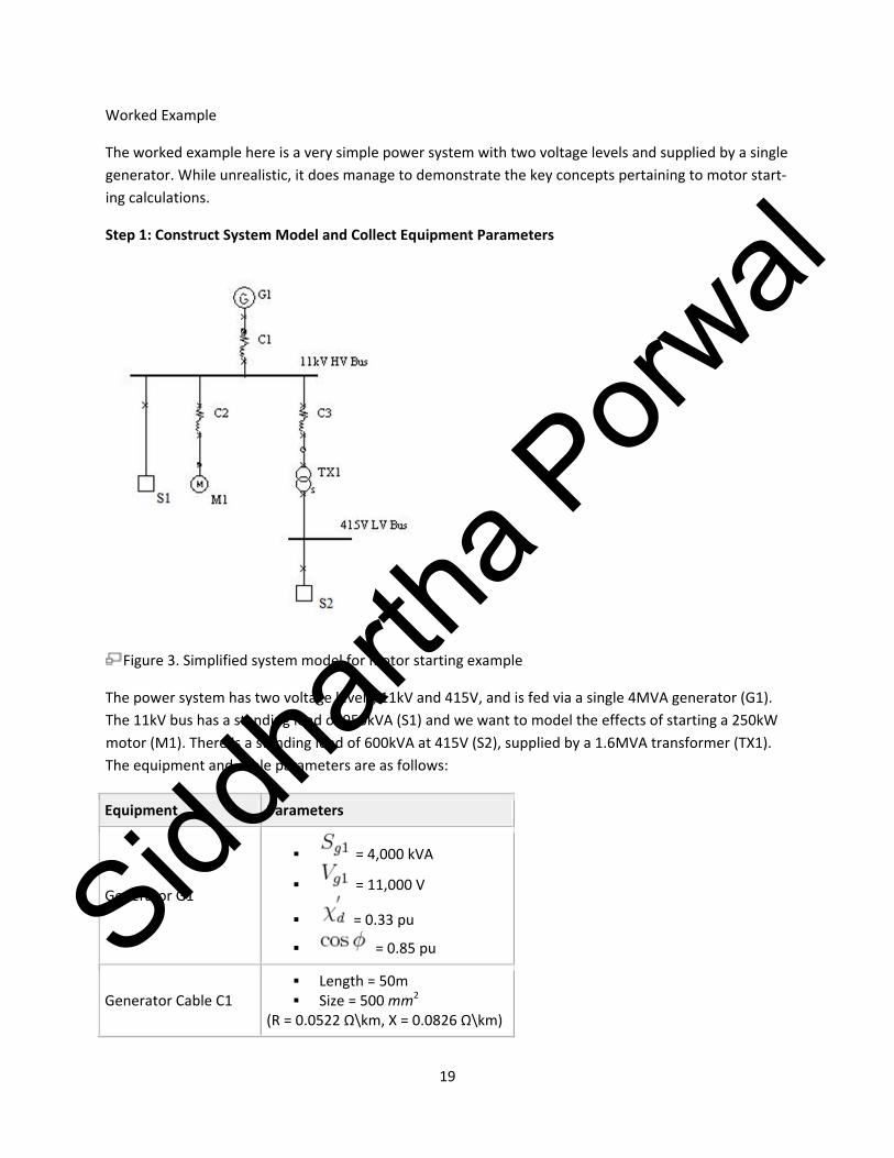
Step 1: Construct System Model and Collect Equipment Parameters
Figure 3. Simplified system model for motor starting example
The power system has two voltage levels, 11kV and 415V, and is fed via a single 4MVA generator (G1).
The 11kV bus has a standing load of 950kVA (S1) and we want to model the effects of starting a 250kW
motor (M1). There is a standing load of 600kVA at 415V (S2), supplied by a 1.6MVA transformer (TX1).
The equipment and cable parameters are as follows:
Equipment Parameters
Generator G1
= 4,000 kVA
= 11,000 V
= 0.33 pu
= 0.85 pu
Generator Cable C1 Length = 50m Size = 500 mm2
(R = 0.0522 Ω\km, X = 0.0826 Ω\km)
Siddha
rtha P
orwal

20
11kV Standing Load S1
= 950 kVA
= 11,000 V
= 0.84 pu
Motor M1
= 250 kW
= 11,000 V
= 106.7 A
= 6.5 pu
= 0.85 pu
= 0.30 pu
Motor Cable C2 Length = 150m Size = 35 mm2
(R = 0.668 Ω\km, X = 0.115 Ω\km)
Transformer TX1
= 1,600 kVA
= 11,000 V
= 415 V
= 0.06 pu
= 12,700 W
= 0%
Transformer Cable C3 Length = 60m Size = 120 mm2
(R = 0.196 Ω\km, X = 0.096 Ω\km)
415V Standing Load S2
= 600 kVA
= 415 V
= 0.80 pu
Step 2: Calculate Equipment Impedances
Using the parameters above and the equations outlined earlier in the methodology, the following im‐
pedances were calculated:
Equipment Resistance (Ω) Reactance (Ω)
Generator G1 0.65462 9.35457
Siddha
rtha P
orwal

21
Generator Cable C1 0.00261 0.00413
11kV Standing Load S1 106.98947 69.10837
Motor M1 16.77752 61.02812
Motor Cable C2 0.1002 0.01725
Transformer TX1 (Primary Side) 0.60027 4.49762
Transformer Cable C3 0.01176 0.00576
415V Standing Load S2 0.22963 0.17223
Step 3: Referring Impedances
11kV will be used as the reference voltage. The only impedance that needs to be referred to this refer‐
ence voltage is the 415V Standing Load (S2). Knowing that the transformer is set at principal tap, we can
calculate the winding ratio and apply it to refer the 415V Standing Load impedance to the 11kV side:
The resistance and reactance of the standing load referred to the 11kV side is now, R = 161.33333 Ω and
X = 121.00 Ω.
Step 4: Construct the Equivalent Circuit
Figure 4. Equivalent circuit for motor starting example Sidd
harth
a Porw
al

22
The equivalent circuit for the system is shown in the figure to the right. The "Near" Thevenin equivalent
circuit is also shown, and we now calculate the equivalent load impedance in the steady‐state con‐
dition (i.e. without the motor and motor cable impedances included):
Similarly the equivalent load impedance during motor starting (with the motor impedances included)
can be calculated as as follows:
Step 5: Calculate the Initial Source EMF
Figure 5. "Near" Thevenin equivalent circuit for motor starting example
Assuming that there is nominal voltage at the 11kV bus in the steady‐state condition, the initial genera‐
tor emf can be calculated by voltage divider:
Vac
Siddha
rtha P
orwal

23
Step 6: Calculate System Voltages During Motor Start
Now we can calculate the transient effects of motor starting on the system voltages. Firstly, the current
supplied by the generator during motor start is calculated:
Next, the voltage at the 11kV bus can be found:
Vac (or 87.98% of nominal voltage)
The voltage at the motor terminals can then be found by voltage divider:
Vac (or 87.92% of nominal voltage)
The voltage at the low voltage bus is:
Vac,
then referred to the LV side = 359.39Vac (or 86.60% of nominal voltage)
Any other voltages of interest on the system can be determined using the same methods as above.
Suppose that our maximum voltage drop at the motor terminals is 15%. From above, we have found
that the voltage drop is 12.08% at the motor terminals. This is a slightly marginal result and it may be
prudent to simulate the system and the motor would start running.
If the results of the calculation confirm that starting the largest motor does not cause any unacceptable voltage levels within the system, then that's the end of it (or perhaps it could be simulated in a power systems analysis software package to be doubly sure!). Otherwise, the issue needs to be addressed, for example by:
Reduce the motor starting current, e.g. via soft‐starters, star‐delta starters, etc Reduce the source impedances, e.g. increase the size of the generator, transformer, supply ca‐
bles, etc The calculation should be performed iteratively until the results are acceptable.
Siddha
rtha P
orwal

24
Computer Software
Motor starting is a standard component of most power systems analysis software (e.g. ETAP, PTW,
ERAC, etc) and this calculation is really intended to be done using this software. The numerical calcula‐
tion performed by the software also solve the power flow problem through an iterative algorithm (e.g.
such as Newton‐Rhapson).
Conclusion :‐
Motor starting is an important issue which must be considered when applying a generator set. The high
current that motors draw when starting causes voltage dips in the system. This may require oversizing
the generator or applying motor starting techniques which maintain this voltage dip at acceptable levels
for the system and its attached components.
Motors, either loaded or unloaded, draw several times rated full load current when starting. This is
termed locked rotor current, or starting kVA (SkVA).
In‐rush current to the motor causes a rapid drop of generator output voltage. In most cases, a 30% volt‐
age dip is acceptable, depending on the equipment you already have on line. The degree of dip must be
identified by an oscilloscope, since mechanical recorders and digital multimeters are too slow.
If in an application where motor starting is a concern, consider the following:
• Change the starting sequence, with largest motors first. More SkVA is available, although it does not provide better voltage recovery time. • Use reduced voltage starters. This reduces kVA required to start a given motor. If you’re starting under load, remember this starting method also reduces starting torque. • Specify oversized generators. • Use wound rotor motors, since they require lower starting current. Wound motors typical cost more, however. • Provide clutches so motors start before loads are applied. While SkVA demand is not reduced, the time interval of high kVA demand is shortened. • Improve the system power factor. This reduces the generator set requirement to produce reactive kVA, making more kVA available for starting. Summarizing it up, for achieving motor system optimization, it requires careful consideration of the
overall motor system and selection of the right equipment, including efficient motors taking their
startup voltage into consideration.
Siddha
rtha P
orwal

25
References :‐
1. http://en.wikipedia.org/wiki/Motor_controller http://en.wikipedia.org/wiki/Motor_soft_starter
2. Three‐phase asynchronous motors Bibliography: Three‐phase asynchronous motors. Generalities and ABB proposals for the coordi‐nation of protective devices. ABB, 2008.
3. Motor Starting http://myelectrical.com/notes/entryid/107/how‐to‐calculate‐motor‐starting‐time#sthash.0g4gZLvk.dpuf
4. Motor starting and protection ‐ Schneider Electric www.schneider‐electric.hu/.../asg‐4‐motor‐starting‐and‐protection.pdf
5. USA, Department Of Energy (DOE) :‐ Improving Motor & Drive System Performance : A Source‐book for Industry https://www1.eere.energy.gov/manufacturing/tech_assistance/pdfs/motor.pdf
6. Induction Motors ‐ Protection and Starting by Viv Cohen ‐ Circuit Breaker Industries, P.O. Box
881, Johannesburg 2000, South Africa
7. Motor Starting Protection and Application Guide by V Cohen. Published by Circuit Breaker In‐dustries Limited.
8. Motor Efficiency, Selection, and Management : A Guidebook for Industrial Efficiency Programs
September 2013 www.motorsmatter.org/CEEMotorGuidebook.pdf
Siddha
rtha P
orwal

26
Appendix A‐1: Comparing Water‐Jet Cutting with Various Other Manufacturing
Processes
The table below summarizes the characteristics, advantages and disadvantages of various starting
methods.
Direct
On Line
Star
Delta
Auto
Transformer
Primary
Resistance
Rotor
Resistance
Electronic
Soft Start
Cost + ++ +++ +++ +++ ++++
Starting Current (xIn) 4 to 8 1.3 to 2.6 1.7 to 4 4.5 < 2.5 2 to 5
Starting Torque 100% 33% 40/65/80% 50% 10 to 70%
Adjustability ‐ + ++ ++ ++ +++
Typical Load Inertia Any Low Low High High Any
Mechanical Impact High Moderate Moderate Moderate Low Low
Motor Type Standard 6‐Terminal Standard Standard Slip‐ring Standard
Resistor Bank ‐ ‐ ‐ Yes Yes ‐
Note: Table data is indicative/typical ‐ variations can occur –
http://myelectrical.com/notes/entryid/95/motor‐starting‐summary#sthash.XzLD1UoO.dpuf
Siddha
rtha P
orwal
Related Documents