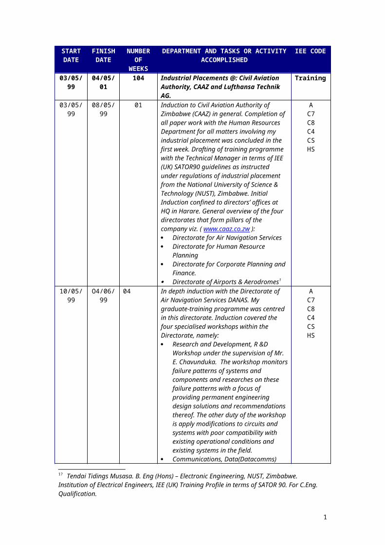
START DATE FINISH DATE NUMBER OF WEEKS DEPARTMENT AND TASKS OR ACTIVITY ACCOMPLISHED IEE CODE 03/05/ 99 04/05/ 01 104 Industrial Placements @: Civil Aviation Authority, CAAZ and Lufthansa Technik AG. Training 03/05/ 99 08/05/ 99 01 Induction to Civil Aviation Authority of Zimbabwe (CAAZ) in general. Completion of all paper work with the Human Resources Department for all matters involving my industrial placement was concluded in the first week. Drafting of training programme with the Technical Manager in terms of IEE (UK) SATOR90 guidelines as instructed under regulations of industrial placement from the National University of Science & Technology (NUST), Zimbabwe. Initial Induction confined to directors’ offices at HQ in Harare. General overview of the four directorates that form pillars of the company viz. ( www.caaz.co.zw ): Directorate for Air Navigation Services Directorate for Human Resource Planning Directorate for Corporate Planning and Finance. Directorate of Airports & Aerodromes 1 A C7 C8 C4 CS HS 10/05/ 99 O4/06/ 99 04 In depth induction with the Directorate of Air Navigation Services DANAS. My graduate-training programme was centred in this directorate. Induction covered the four specialised workshops within the Directorate, namely: Research and Development, R &D Workshop under the supervision of Mr. E. Chavunduka. The workshop monitors failure patterns of systems and components and researches on these failure patterns with a focus of providing permanent engineering design solutions and recommendations thereof. The other duty of the workshop is apply modifications to circuits and systems with poor compatibility with existing operational conditions and existing systems in the field. Communications, Data(Datacomms) A C7 C8 C4 CS HS 1? Tendai Tidings Musasa. B. Eng (Hons) – Electronic Engineering, NUST, Zimbabwe. Institution of Electrical Engineers, IEE (UK) Training Profile in terms of SATOR 90. For C.Eng. Qualification. 1

Welcome message from author
This document is posted to help you gain knowledge. Please leave a comment to let me know what you think about it! Share it to your friends and learn new things together.
Transcript
START DATE
FINISH DATE
NUMBER OF
WEEKS
DEPARTMENT AND TASKS OR ACTIVITY ACCOMPLISHED
IEE CODE
03/05/99 04/05/01 104 Industrial Placements @: Civil Aviation Authority, CAAZ and Lufthansa Technik AG.
Training
03/05/99 08/05/99 01 Induction to Civil Aviation Authority of Zimbabwe (CAAZ) in general. Completion of all paper work with the Human Resources Department for all matters involving my industrial placement was concluded in the first week. Drafting of training programme with the Technical Manager in terms of IEE (UK) SATOR90 guidelines as instructed under regulations of industrial placement from the National University of Science & Technology (NUST), Zimbabwe. Initial Induction confined to directors’ offices at HQ in Harare. General overview of the four directorates that form pillars of the company viz. ( www.caaz.co.zw ): Directorate for Air Navigation Services Directorate for Human Resource Planning Directorate for Corporate Planning and
Finance. Directorate of Airports & Aerodromes1
AC7C8C4CSHS
10/05/99 O4/06/99 04 In depth induction with the Directorate of Air Navigation Services DANAS. My graduate-training programme was centred in this directorate. Induction covered the four specialised workshops within the Directorate, namely: Research and Development, R &D
Workshop under the supervision of Mr. E. Chavunduka. The workshop monitors failure patterns of systems and components and researches on these failure patterns with a focus of providing permanent engineering design solutions and recommendations thereof. The other duty of the workshop is apply modifications to circuits and systems with poor compatibility with existing operational conditions and existing systems in the field.
Communications, Data(Datacomms) Workshop under the supervision of Mr. C. Kanojerera. The Comms workshop is responsible for communications equipment maintenance while the Data workshop is responsible for data related maintenance, software installations , Databases eg Ingress and Aeronautic Fixed Telecommunications Network (AFTN) software and databases
Radar and Navigation Workshop under the supervision of Mr. M. Kurerwa for maintenance of navigational equipment: RADAR, VOR, DME and NDB,s
AC7C8C4CSHS
START FINISH NUMBER DEPARTMENT AND TASKS OR IEE CODE
1? Tendai Tidings Musasa. B. Eng (Hons) – Electronic Engineering, NUST, Zimbabwe. Institution of Electrical Engineers, IEE (UK) Training Profile in terms of SATOR 90. For C.Eng. Qualification.
1

DATE DATE OF WEEKS
ACTIVITY ACCOMPLISHED
07/06/99 11/06/99 01 Appreciation of company structure under the guidance of the Technical Manager Mr I. Sibanda. This included issues like the company’s Mission Statement, Vision, 5 Year Strategic Plan, Shareholding structure (100% Gvt at the time), the ongoing restructuring after its transformation from being the Department of Civil Aviation, DCA under the Ministry of Transportation & Energy into a fully fledged commercial parastatal. Overview and appreciation of all major projects that were taking place company-wide, namely: 11KV Electrical Ratification for Harare
International Airport which was meant for the reticulation of the 11KV power network for the Airport
New Harare International Airport Terminal Building project for the construction of the new Harare International Airport Terminal
Harare International Airport Civil Works and Refurbishment of the old Terminal Building which entailed improvements of the interior design of the lounges ie. Departure, Arrivals and Main Concourse.
Rehabilitation of Airfield which involved new categorised airfield lights
Air Traffic Control, ATC Tower equipment project which entailed supply of control tower equipment
VSAT System project which involved supply of VSAT Satellite terminals
Victoria falls airport runway and upgrading of existing Terminal Building
ORAT Program Project.
Appreciation of the Directorate of Air Navigation’s broad responsibilities which primarily are:1. Provision and management of Air Traffic
Services in Zimbabwe2. Provision and Maintenance of
Communication, Navigation and Surveillance/ Air Traffic Management Systems (CNS / ATM )
3. Regulation and enforcement of Flight Safety Standards in Zimbabwe.
Appreciation of the three Departments that are structures designed to deliver these service requirements, which are:1. Air Navigation Technical Services (ANTS)
for Planning and Maintenance Engineering, Air Navigation System Maintenance & Mechanical and Rigging
2. Air Traffic Services Department (ATS) for Air Traffic Control, Aeronautical
AC7C8C4CSHS
START DATE
FINISH DATE
NUMBER OF
DEPARTMENT AND TASKS OR ACTIVITY ACCOMPLISHED
IEE CODE
2

WEEKS07/06/99 11/06/99 01 Information Services, Communications
Operations3 Flight Safety Standards as composed of Aerodromes Inspectorate, Airworthiness Inspectorate, Flight Operations Inspectorate and Licensing.
AC7C8CSHS
14/06/99 30/07/99 06 To appreciate CAAZ system-wide I was attached to the auditing section that was undertaking an inventory analysis project system-wide as a technical assistant on issues involving electronic & Electrical components and systems. I flew with the team to all airports country-wide namely:1. Charles Prince Airport2. Kariba Airport3. Victoria Falls International Airport4. Bulawayo International Airport5. Buffalo Range Airport6. Hwange Airport7. And finally Harare International Airport
ABC3CS
02/08/99 10/09/99 06 Safety Training Course with Lufthansa German Airlines and the Safety Branch at CAAZ
To appreciate the totality of Air Navigation Services for both ground and airborne systems, an agreement was made with Lufthansa Technik AG. Subsidiary of Lufthansa German Airlines which was operating two types of aircraft to Harare International Airport:1. Boeing 747-4002. Airbus 340-300
The Agreement facilitated for a training programmme with Lufthansa to run concurrently with my training @ CAAZThe Regional Manager facilitated this Agreement for Lufthansa based at the Regional Harare offices Mr Herbert Reichle. The Lufthansa line engineers I worked with throughout my training.were Joerg Wolter, S. Stiblitz and Frank Konig. The training agreement culminated in a six(6) week Safety Training course with Lufthansa Technik AG and the following undertakings: Registration with Goethe Institute for
German Classes ( Deutsch Als Fremdesprach 1,2 & 3)
Tour of Lufthansa Technik Training facility at Frankfurt
The overall or concurrent Training with Lufthansa had the following objectives to be achieved: Familiarisation with the Maintenance
Handbook or Engineering Maintenance
ABC3C4C5CSHS
START DATE
FINISH DATE
NUMBER OF
DEPARTMENT AND TASKS OR ACTIVITY ACCOMPLISHED
IEE CODE
3

WEEKS02/08/99 10/09/99 06 Order for Lufthansa Technik AG as specified in
their Tecknik Ordnung Handbuch. Familiarisation with computer aided
maintenance techniques for the Airbus 340, Airbus 320 and Boeing 747-400 aircraft using Jeppersons Maintenance software Systems
Aircraft Faults Classifications, Class 1 to Class 6 and their implications on maintenance procedures and decisions.
Checks Classifications; A, B, C,D. With D check involving complete aircraft overhaul.
Interpretation of the Flight Management Computer (FMC) data and Flight Management Systems (FMS) like avionics, communication systems, microprocessor controlled lighting systems, redundancy of safety critical systems etc.
Insight into Lufthansa Tecknik AG also available on the following website
www.lufthansa-technik.de My maintenance routines on Lufthansa
generally ran at a frequency of three days a week (Tuesdays, Thursdays, and Saturdays), CAAZ training requirements took precedence however, though I could be released to Lufthansa Technik special programmes at the discretion of CAAZ management
ABC3C4C5CSHS
13/09/99 10/12/99 12 RADAR TRAINING & MAINTENANCE:Technical Data, Theory, Maintenance Work With Maintenance Teams, Fault Finding & Troubleshooting Hands on Experience. Inclusive of Lufthansa concurrently runningt Training.
Appreciation of the fact that Zimbabwe is a signatory of the International Civil Aviation Organisation (ICAO), Chicago Convention of 1944 which binds the country into providing Civil Aviation Services in Accordance to laid down specifications and standards ie. International Standards
Appreciation of agreement between PTC carriers and CAAZ on use of PTC leased telephone lines for RADAR data transmission between Bulawayo International Airport , Gokwe, Masvingo, Mutorashanga, Rusape and Harare Area Control Centre (ACC) at the Harare International Airport
Use of RADAR in Air Traffic Services, dualization or redundancy factors of RADAR data systems to achieve ideally 100% availability of RADAR data.
BC1C3C4C5C6CSHS
START DATE
FINISH DATE
NUMBER OF
WEEKS
DEPARTMENT AND TASKS OR ACTIVITY ACCOMPLISHED
IEE CODE
4

13/09/99 10/12/99 12 RADAR technical description, the dual Watchman RADAR system at Harare consisting of S-Band primary radar operating in conjunction with a secondary surveillance radar (SSR). The primary radar instrumented range of 80nm(nautical miles) and the SSR instrumented range of 250nm.
Structure and facility of RADAR at Harare International Airport
Facilities at Air Traffic Control (ATC), link with the watchman radar system in Bulawayo. Transfer of Speech and radar between these two sites and the are other sites using VHF radios and PTC leased lines
PRIMARY RADAR EQUIPMENT. Location and structure, main and auxiliary beams, primary radar aerial together with the associated turning gear and 5-channel joint. RF switches and signals control, waveguide changeover switch, remote control monitoring system, Signal Processing Rack (SPR). RF amplifiers, S-Band Transmitters. Plot extractor and plot filter/combiners. Data switch used for selection of either channel A/B. Fibre optic multiplexer/modem for data transfer, control and status information between container and Air Traffic Control. Watchman 16” monitor display of RADAR plot data from primary and secondary surveillance radar processing functions. Functional Issues, low power RF drive signals, travelling wave tube (TWO)Pulse Repetition Interval(PI), Phase(I) and Qaudrature(Q) data outputs to Adaptive Moving Target Detector (AMTD), Ground Clutter Filter (GCF), Moving Clutter Filter (MCF), Normal Radar (NR).
Azimuth Distribution, inductosyn transducer, azimuth change pulses (ACP) Azimuth Reset Pulses (ARP).
Remote Control and Monitoring System (RCMS)
SECONDARY SURVEILLANCE RADAR Radar Processing and Displays Power Supplies & UPS supplies.
BC1C3C4C5C6CSHS
START DATE
FINISH DATE
NUMBER OF
WEEKS
DEPARTMENT AND TASKS OR ACTIVITY ACCOMPLISHED
IEE CODE
13/12/99 28/01/00 06 INSTRUMENT LANDING SYSTEMS, ILS B
5

Technical Data, Maintenance Works With Maintenance Teams, Faults & Troubleshooting Techniques. Inclusive of Lufthansa Training.
ILS 4000 System. Layout. Localizer(LOC) determination of ‘on –course line’ ,lateral guidance ie. ‘fly-left’ and ‘fly- right’. Glide Slope (GS) GS angle 2.5 ….3.0, ‘fly-up’ and ‘fly-down’ vertical guidance. Outer Marker (OM), distance to touchdown point ~7200m. Middle Marker (MM) ~1500m to touchdown point. Inner Marker (IM) ~ very close to touchdown point. Specifications of systems: carrier frequency range. Amplitude modulation and navigational frequencies, modulation depth, criteria for defining course line, lateral and angular displacement sensitivities, identification and minimal coverage. Standards. antenna patterns. Dual installation. ILS 4000 transmitter control and Monitoring. Bus system for transmitter and monitors. Built In Test Equipment, BITE.
C1C3C4C5C6CSHS
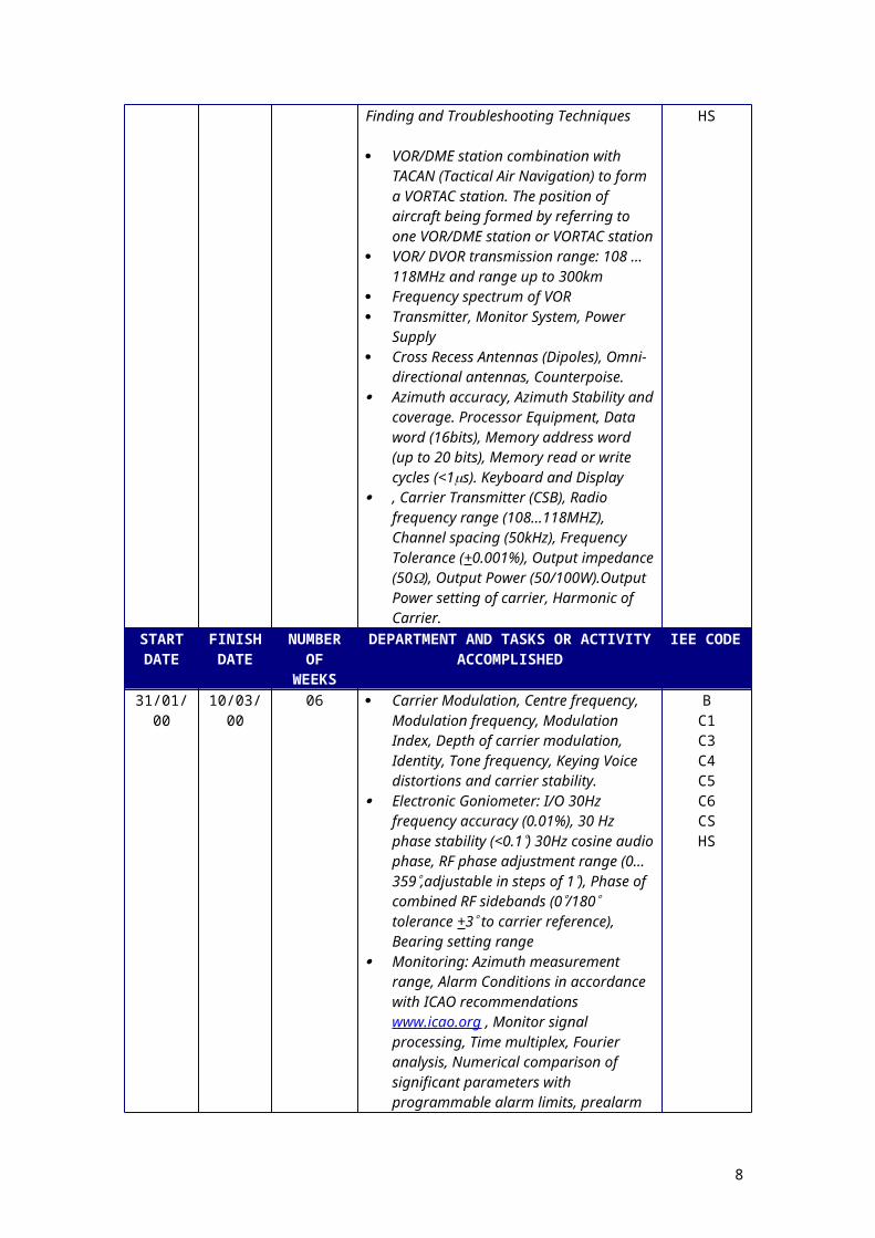
31/01/00 10/03/00 06 Very High Frequency Omni-directional Radio Range (VOR) / DVOR (D= Doppler) Beacon Equipment and VOR/DME (Distance Measuring Equipment) Methods Training. Inclusive of. Lufthansa training.Technical Data training, Maintenance routines with Maintenance Teams, Fault Finding and Troubleshooting Techniques
VOR/DME station combination with TACAN (Tactical Air Navigation) to form a VORTAC station. The position of aircraft being formed by referring to one VOR/DME station or VORTAC station
VOR/ DVOR transmission range: 108 …118MHz and range up to 300km
Frequency spectrum of VOR Transmitter, Monitor System, Power Supply Cross Recess Antennas (Dipoles), Omni-
directional antennas, Counterpoise. Azimuth accuracy, Azimuth Stability and
coverage. Processor Equipment, Data word (16bits), Memory address word (up to 20 bits), Memory read or write cycles (<1s). Keyboard and Display
, Carrier Transmitter (CSB), Radio frequency range (108…118MHZ), Channel spacing (50kHz), Frequency Tolerance (+0.001%), Output impedance (50), Output Power (50/100W).Output Power setting of carrier, Harmonic of Carrier.
BC1C3C4C5C6CSHS
START DATE
FINISH DATE
NUMBER OF
WEEKS
DEPARTMENT AND TASKS OR ACTIVITY ACCOMPLISHED
IEE CODE
31/01/00 10/03/00 06 Carrier Modulation, Centre frequency, Modulation frequency, Modulation Index,
BC1
6

Depth of carrier modulation, Identity, Tone frequency, Keying Voice distortions and carrier stability.
Electronic Goniometer: I/O 30Hz frequency accuracy (0.01%), 30 Hz phase stability (<0.1) 30Hz cosine audio phase, RF phase adjustment range (0…359,adjustable in steps of 1), Phase of combined RF sidebands (0/180 tolerance +3 to carrier reference), Bearing setting range
Monitoring: Azimuth measurement range, Alarm Conditions in accordance with ICAO recommendations www.icao.org , Monitor signal processing, Time multiplex, Fourier analysis, Numerical comparison of significant parameters with programmable alarm limits, prealarm for azimuth, programmable alarm delay, monitor self test, Intelligent decisions upon monitors “happy/unhappy” and monitor self test results, Fully dualized hardware and software
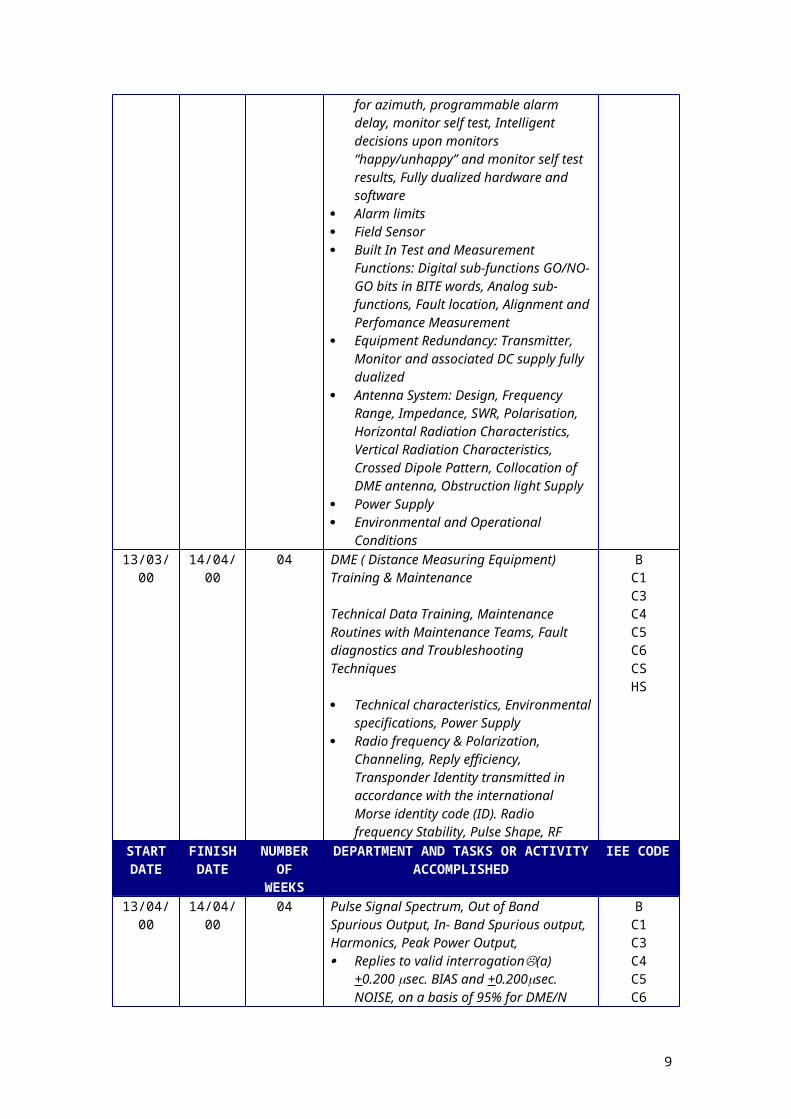
Alarm limits Field Sensor Built In Test and Measurement Functions:
Digital sub-functions GO/NO-GO bits in BITE words, Analog sub-functions, Fault location, Alignment and Perfomance Measurement
Equipment Redundancy: Transmitter, Monitor and associated DC supply fully dualized
Antenna System: Design, Frequency Range, Impedance, SWR, Polarisation, Horizontal Radiation Characteristics, Vertical Radiation Characteristics, Crossed Dipole Pattern, Collocation of DME antenna, Obstruction light Supply
Power Supply Environmental and Operational Conditions
C3C4C5C6CSHS
13/03/00 14/04/00 04 DME ( Distance Measuring Equipment) Training & Maintenance
Technical Data Training, Maintenance Routines with Maintenance Teams, Fault diagnostics and Troubleshooting Techniques
Technical characteristics, Environmental specifications, Power Supply
Radio frequency & Polarization, Channeling, Reply efficiency, Transponder Identity transmitted in accordance with the international Morse identity code (ID). Radio frequency Stability, Pulse Shape, RF
BC1C3C4C5C6CSHS
START DATE
FINISH DATE
NUMBER OF
WEEKS
DEPARTMENT AND TASKS OR ACTIVITY ACCOMPLISHED
IEE CODE
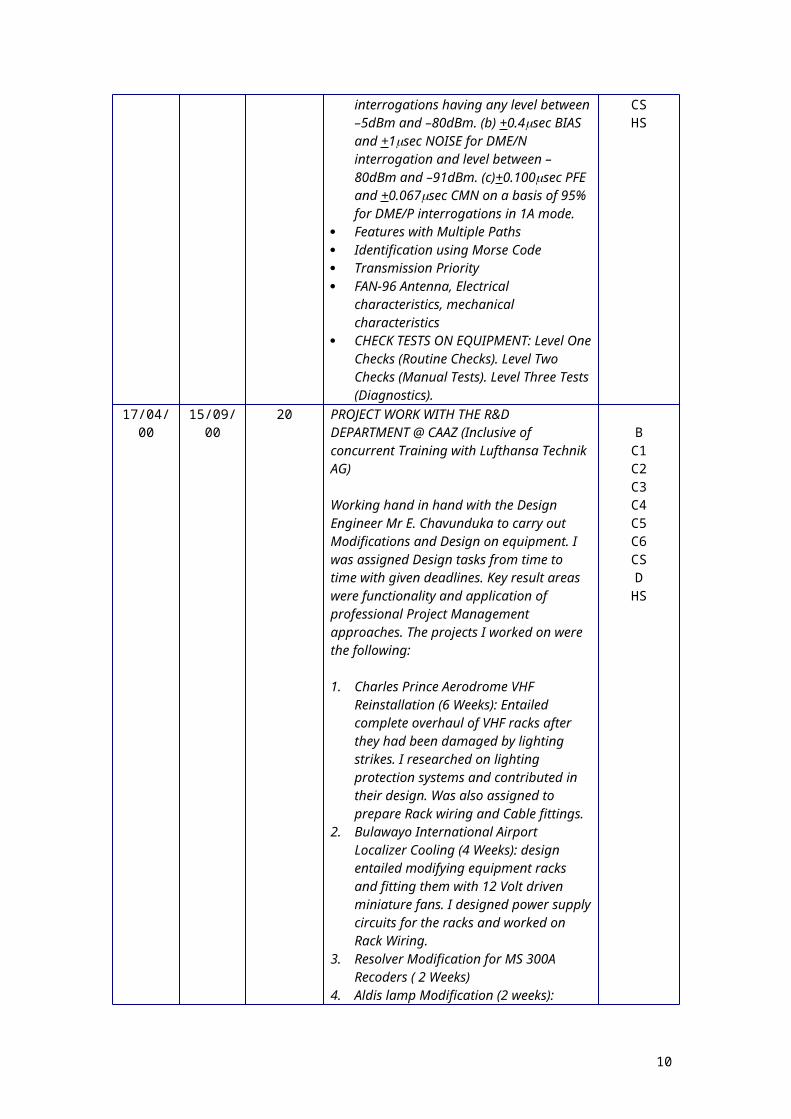
13/04/00 14/04/00 04 Pulse Signal Spectrum, Out of Band Spurious Output, In- Band Spurious output, Harmonics, Peak Power Output,
BC1C3
7
Replies to valid interrogation(a)+0.200 sec. BIAS and +0.200sec. NOISE, on a basis of 95% for DME/N interrogations having any level between –5dBm and –80dBm. (b) +0.4sec BIAS and +1sec NOISE for DME/N interrogation and level between –80dBm and –91dBm. (c)+0.100sec PFE and +0.067sec CMN on a basis of 95% for DME/P interrogations in 1A mode.
Features with Multiple Paths Identification using Morse Code Transmission Priority FAN-96 Antenna, Electrical characteristics,
mechanical characteristics CHECK TESTS ON EQUIPMENT: Level
One Checks (Routine Checks). Level Two Checks (Manual Tests). Level Three Tests (Diagnostics).
C4C5C6CSHS
17/04/00 15/09/00 20 PROJECT WORK WITH THE R&D DEPARTMENT @ CAAZ (Inclusive of concurrent Training with Lufthansa Technik AG)
Working hand in hand with the Design Engineer Mr E. Chavunduka to carry out Modifications and Design on equipment. I was assigned Design tasks from time to time with given deadlines. Key result areas were functionality and application of professional Project Management approaches. The projects I worked on were the following:
1. Charles Prince Aerodrome VHF Reinstallation (6 Weeks): Entailed complete overhaul of VHF racks after they had been damaged by lighting strikes. I researched on lighting protection systems and contributed in their design. Was also assigned to prepare Rack wiring and Cable fittings.
2. Bulawayo International Airport Localizer Cooling (4 Weeks): design entailed modifying equipment racks and fitting them with 12 Volt driven miniature fans. I designed power supply circuits for the racks and worked on Rack Wiring.
3. Resolver Modification for MS 300A Recoders ( 2 Weeks)
4. Aldis lamp Modification (2 weeks): Project Entailed increasing its luminance output ie. Modifying their Power supply circuits.
5. Kariba airfield Robot Rewiring (1 week):
BC1C2C3C4C5C6CSD
HS
START DATE
FINISH DATE
NUMBER OF
WEEKS
DEPARTMENT AND TASKS OR ACTIVITY ACCOMPLISHED
IEE CODE
17/04/00 15/09/00 20 6 NDB Charger modification (1 week)7 Standby Power Change Overboard for
Solera (4 Weeks)
B, C1, C2, C4, C5, C6,CS, D, HS
8
18/09/00 04/05/01 30 8 SECURITY ALARMS FOR REMOTE SITES Eg. RADAR SITES, Glide Slope equipment, VOR, DME, NDB’s etc. The project came towards the end of my industrial. I was given the task of researching on it and to implement it as an Honours Project in my final year at National University of Science & Technology, NUST while based at Bulawayo International Airport. Therefore my last 2 weeks were spent arranging for my transfer to Bulawayo and organising components and all research tools I were to use in Bulawayo. This served as my directed objective training (DOT) project. My training with Lufthansa ceased as I was moving out of Harare Airport and Lufthansa was also pulling out of Zimbabwe citing fall of business due to a tense political climate at the height of the Government sponsored Fast –Track Land Reform Exercise. I went back to NUST for my 5th and Final year while carrying on with this DOT project as my Honours Project. CAAZ funded the project requirements 100%. My Training Contract was extended by a year. I was meant to report for work at Bulawayo Airport at least twice a week to facilitate the monitoring of my progress by the Airport Manager Mr. P.P. Dewa.
I specialized in: Embedded Computer Control Systems And Industrial Control
Hence I developed an Embedded systems based Model for Bulawayo Airport.Project Title: Embedded Systems Based Airport Security
System
Project Description I developed the Model using PIC16C84
processor that was receiving violation signals from Passive Infra- red detectors , PIRs, magnetic switches and smoke detector switches
Testing of Model was successful and the installation phase followed during my Graduate Trainee Phase in the first 3 months.
BC1C2C3C4C5C6CSD
HS
START DATE
FINISH DATE
NUMBER OF
WEEKS
DEPARTMENT AND TASKS OR ACTIVITY ACCOMPLISHED
IEE CODE
04/06/01 31/12/01 24 6 months Post Graduate Training @: Civil Aviation Authority Zimbabwe CAAZ (www.caaz.co.zw)
Training
Directed Objective Training Completion: B, D
9
Development of a working system from my model to be installed at Bulawayo International Airport.
Testing and installation was completed in three months. After three months system operational testing, system was commissioned.
C1C2C3C4C5C6CSHS
START DATE
FINISH DATE
NUMBER OF
WEEKS
DEPARTMENT AND TASKS OR ACTIVITY ACCOMPLISHED
IEE CODE
06/01/03 24/10/03 36 Work at Civil Aviation of Zimbabwe, CAAZwww.caaz.co.zw Job Title: Electronic Engineer, (Junior Scale).
CPDContinuedProf. Dev.
06/01/03 05/03/03 08 Project Management & Maintenance Strategies Training (8 Weeks)
Appreciation and Training in Following Issues
Scheduling and Control Charts eg GANNT CHART
Appreciation of terms used in Project Management: Activity, Activity Duration, Critical Activity, Critical Path, Dummy Activity, Earliest Finish (EF), earliest Start (ES), Event, Latest Finish (LF), Latest Start(LS), Most Likely Time (Tm.), Optimistic Time (To), Pessimistic Time (Tp), Predecessor Activity, Slack, Successor Activity
Critical Path Method, CPM Program Evaluation and Review Technique Computer Software for Project
Management (Microsoft Project) Drawing Up Maintenance Strategies Repair Programs Preventive Maintenance (PM) Programs PM and operations strategies Scheduling of PM activities PM Database Requirements Modern approaches to PM Machine reliability Trends in Maintenance
BC1C2C3C4C5C6C8CSHS
07/03/03 21/03/03 03 Very Small aperture Terminals (VSAT) TRAINING
The installation of VSAT resulted in the Training of CAAZ staff on the equipment , principles of operations and the broad areas of its applications
TrainingB, C1, C2, C3, C4, C5, C6, C8, CS, HS
START DATE
FINISH DATE
NUMBER OF
WEEKS
DEPARTMENT AND TASKS OR ACTIVITY ACCOMPLISHED
IEE CODE
06/01/03 24/10/03 36 Work at Civil Aviation of Zimbabwe, CAAZwww.caaz.co.zw Job Title: Electronic Engineer, (Junior Scale).
CPDContinuedProf. Dev.
24/03/03 24/10/03 28 VICTORIA FALLS (ZIMBABWE) – KASANE (BOTSWANA) REPEATER PROJECT:
B, DC1
10

Project Scope: To establish VHF communication Link
between to two Airports. Design of a Repeater Link using Becker 3201, 5 Watt radios. I worked on this project as the Project Engineer for 7 months.
Project was Installed and commissioned. The VHF link was mounted at a Post & Telecommunications Corporation, PTC site called MARS 1060. The site is 34km (line of sight) from Victoria Falls Airport. About half-way to Kasane Airport. The threshold tests managed to have the system raising Kasane airport at strength four and Livingstone Airport at strength five.
Modification design on Becker 3201 worked perfectly.
GENERAL MAINTENANCE WORK WHILE BASED AT VICTORIA FALLS AIRPORT FOR TWO MONTHS. INVESTIGATING CIRCUITS THAT REQUIRE MODIFICATIONS AND DRAWING CIRCUIT AND SYSTEM BEHAVIOUR PATTERNS, DRAWING UP A MAINTENANCE STRATEGY FOR THE VICTORIA FALLS INTERNATIONAL AIRPORT.
***************************************I then decided to leave CAAZ for NRZ Signalling Engineering to persue a career in that field in order to diversify my skills base as aviation industry had suffered negatively from the 9/11 attacks in New York. Prospects for growth were looking gloom as far as I was concerned. The opportunity to take up a Rail Signalling career looked really attractive to me.***************************************
C2C3C4C5C6CSHS
START DATE
FINISH DATE
NUMBER OF
WEEKS
DEPARTMENT AND TASKS OR ACTIVITY ACCOMPLISHED
IEE CODE
01/11/02 05/05/03 24 Trainee Signal Engineer With The National Railways Of Zimbabwe, NRZ. NRZ is a Rail Operations Company and the owner of the infrastructure. It controls a rail infrastructure of ~ 2885km of rail line of which 413km is
Training.
11
Electrified.01/11/02 02/11/02 01 ASSESSMENT OF MY TRAINING
REQUIREMENTS
After completion of my paperwork with the employer I held a meeting with the then Acting Principal Signalling Engineer, Mr Funny Zindoga. The meeting aimed at assessing my training requirements. I was asked to submit all my previous training reports and recommendations.
The fact that I had successfully completed a postgraduate Training Programme at CAAZ. My competencies in Telecommunication systems and working in a safety critical environment were taken into consideration. Civil Aviation Authority recommended to the effect that I had completed my postgraduate Training.
The training requirements of the Institution of Electrical Engineers, IEE (UK) of the SATOR 90 terms were cross-referenced with the NRZ training whose IEE code is197B81 and together with my previous training records.
I was determined that a 6 months conversion training programme to Signal Engineering would be appropriate and in line with professional requirements of IEE as well as in keeping with NRZ provisions for discretional issues pertaining training. These six months of training were meant to focus on the Directed Signalling Training component of the Signal Branch’s Training since the other portions of the programme would equate to a repetition to what I had done in my previous training. The other key component was to be an induction into the NRZ system by drafting a comprehensive Induction programme.
I was instructed by the Principal Engineer to prepare a fresh logbook and posted to the Drawing Office under Mr John Oliver so as to familiarize myself with signalling engineering and the branch’s modus operandi.
ACS
START DATE
FINISH DATE
NUMBER OF
WEEKS
DEPARTMENT AND TASKS OR ACTIVITY ACCOMPLISHED
IEE CODE
03/05/99 09/09/00 70 Trainee Signal Engineer With The National Railways Of Zimbabwe, NRZ.
Training.
01/11/02 31/12/02 08 TRAINING AT THE DRAWING OFFICE: AB
12

The functions of the Drawing Office were illustrated to me and its crucial role in record keeping and design was highlighted by Mr. J. Oliver, the Assistant Engineer Design.
I acquired a broad understanding of Signal Engineering as a field of practice through lectures on a one to one basis with Oliver and the help of the Drawing Office Staff. I also spent time researching through the internet on topics that are signalling related.
Lectures and illustrations were based on Hrarare – Headlands CTC system, Mutare-Headlands CTC system, Thompson Junction and Hwange signal layout diagrams, drawings and charts
I practised an in-depth understanding of drawings by referring to the Nomenclature Handbook to interpret circuit drawings. Appreciated the Safety aspects of signalling.
Website Research was on the following sites: railway technical pages www.trainweb.org German Railroad Signal Systems, Information on German Railway aspects covering H/V, HL, RS , other systems as well as rail signs www.home.t-online.de/home/wmeyenberg/eisenbahn, Railway Signalling & Operations of CTC www.broadway.pennsyrr.com/rail, Institution of Railway Signal Engineers, IRSE. The home page of the professional institution for those engaged in railway signalling, telecommunications and related matters www.irse.org, British railway signalling, how it works by Clive Feather www.davros.org/rail/signalling/articles, Austro-Swiss railway site www.8ing.at/smi, Software verification centre, Signal Design Tools www.svrc.it.uq.edu.au, Attachment report from a sri-lankan B. Eng Electronics attached to the railway authority www.jayan.tripod.com.
BLOCKS: the division of each track into blocks, each block protected by a signal placed at its entrance, Red and Green aspects in signalling
THE TRACK CIRCUIT: A means of detecting track occupancy by trains. Track circuit power supply, Normally energised relay for fail safe considerations. Rail insulation. Track feed resistor.Shunt current
C1C2C3C4C5C6CSD
HS
START DATE
FINISH DATE
NUMBER OF
WEEKS
DEPARTMENT AND TASKS OR ACTIVITY ACCOMPLISHED
IEE CODE
03/05/99 09/09/00 70 Trainee Signal Engineer With The National Railways Of Zimbabwe, NRZ.
Training.
01/11/02 31/12/02 08 Minimum length of Track circuit being determined by the required degree of while maximum length is determined by weather
BC1C2
13
conditions Appreciation of other vacancy and
occupancy detection methods such Axle Counting Systems like the Siemens Az 350 U Microcomputer Axle Counting System. The Jeumont Shneider high impulse Track Detection System.
MULTI Aspect Signalling 4 Aspect Signalling Automatic Warning System, AWS, due to
effects of SPAD ( Signal Passed at Danger) ROUTE Signalling: Junctions, Approach
and track Locking, Signals at Junctions, Interlocking, Route Signalling, The Operator’s Display, Route Setting, Train Movement sequences
Metro Signalling And ATP: Metro Signalling, The Overlap, track Circuited Overlaps, Automatic Train Protection, ATP speed codes, Operating with ATP, Distance To Go, Speed Monitoring, Operations with Distance To Go.
Automatic Train Control (ATP): The ATC Package, Moving Block
ATP transmission and Moving Block: ATP Code Transmission, Beacon Transmission, Operation with Beacons, Intermittent Updates, Moving Block, The theory of moving block and Radio Transmission.
SINGLE LINE OPERATION: Single line operation, Timetables, Familiarization with the Train Speed Rules, Train Spacing, train orders, track warrants, Unsignalled Operations, Centralised Traffic Control, CTC, Staff and Ticket System, Electronic Token Blocks, Radio Electronic Token Block (RETB) as is used by the BBR section of the Heany- Junction to Beitbridge Route.
I also familiarised myself with the Train Working Regulations (TWR) and the Signal Maintenance handbook.
SIGNALS: Circuit wiring appreciation for various Signals Lamps or Posts. Classifications of Signals. Controlled/ Automatic, Automatic Blocking and Automatic Approach Signals. High Controlled Signals and Dwarf Controlled Signals
C3C4C5C6CSHS
START DATE
FINISH DATE
NUMBER OF
WEEKS
DEPARTMENT AND TASKS OR ACTIVITY ACCOMPLISHED
IEE CODE
03/05/99 09/09/00 70 Trainee Signal Engineer With The National Railways Of Zimbabwe, NRZ.
Training.
01/11/02 31/12/02 08 POINTS MACHINES, Appreciation of all Points Machines in use in the NRZ establishment eg. GRS 5A, Westinghouse M5, and Siemens S700. Operational issues
BC1C2C3
14

of Point machines. Drive Rod, Switchblade, Stock Rail, Tie Bar, Motor, Long Detector Rod, Short Detector Rod etc.Discussions and lectures on Point machines by Oliver elightened me on various issues like, snubbing circuits and reactance based circuits in Points machines.
Gate Barriers and Level Crossings, Flash light instalments and their link to the interlocking system. Booms, Warning Signals, Breaking Distance
To reinforce all my understanding, a week of site visits to Bulawayo Station yard was arranged with the Assistant Engineer, New Works P. Masden. We toured the Control Room, Relay House, Points Machines, Operator Console and practical explanations of Route setting procedure. Interlocking at Bulawayo Yard
C4C5C6CSHS
01/11/02 31/12/02 08 DIRECTED OBJECTIVE TRAINING, VICTORIA FALLS BRIDGE RESIGNALLING PROJECT
I was assigned to work on a project that had been in the drawing office for about 7years. The bridge life is being threatened by loading stresses, which are not compatible with its age and design. The bridge was built in 1902 and it was primarily meant for rail traffic. An extension of design to cover road traffic was made as the construction project unfolded. Rail Traffic is supported directly by the main members of the Bridge while the roadside is supported by a component force of the main members. The current loads of Traffic with 56 Tonne trucks are unsustainable. This necessitated for the design of a dedicated traffic system that would make the movement of road and rail traffic to be mutually exclusive so as to avoid destructive resonant harmonics that could lead to collapse or deterioration of the bridge. The bridge is not only an economic link between Zimbabwe and Zambia but a tourist and world heritage given Honours by the American Institution of Civil Engineers, Zimbabwe Institution of Engineers, ZIE and the Zambian Engineering Council.
BC1C2C3C4C5C6CSHS
START DATE
FINISH DATE
NUMBER OF
WEEKS
DEPARTMENT AND TASKS OR ACTIVITY ACCOMPLISHED
IEE CODE
03/05/99 09/09/00 70 Trainee Signal Engineer With The National Railways Of Zimbabwe, NRZ.
Training.
01/11/02 31/12/02 08 The project specification involved the design of a system that would allow traffic to move one way into Zambia for 2 minutes, have both Robots Red for 30 seconds to
BC1C2C3
15
allow traffic to clear bridge; Allow Traffic to move into Zimbabwe for 2minutes and then get both Traffic lights for 30 seconds to allow Traffic to clear the bridge; The system would have to repeat this sequence continually until it was interrupted.
The system sequence was meant to be able to be reset in the event the cycle lost the sequence
Interruption was meant to come from a Train approach. The Train has to be detected at least 2 minutes away from the bridge.
At the point of detection af train the Robots should both go to Red and the Booms should close
The system should be able to detect direction of Train and release system back to normal robot sequence as soon as the Train has cleared or crossed the bridge.
I managed to have a completed Relay Based Design by the 4th of December, which utilized JR relays, for timing circuits. I explained the Design to the Assistant Design Engineer and it was approved. I went on to do some tests with a few relays at training school but it soon became evident that there was no stock of relays to carry out the project. Attempting to purchase the relays was also going to prove too costly. I then opted for an Embedded control based design that met the specifications and even surpassed them in terms of versatility using the PIC16FXXX family of processors.
In the process of this project scope I had an Appreciation of equipment problems within the NRZ eg Lighting strikes and the importance of lighting protection systems and system checks towards rainy season.
Appreciation of drawing office procedures to amendments, new designs, modifications. Red and Yellow works.
The project afforded me a perfect platform e to apply the knowledge I had accumulated at the Drawing Office and indeed Signal engineering in general, it was a good application tool.
Full project details are available with my Logbook.
C4C5C6CSHS
START DATE
FINISH DATE
NUMBER OF
WEEKS
DEPARTMENT AND TASKS OR ACTIVITY ACCOMPLISHED
IEE CODE
03/05/99 09/09/00 70 Trainee Signal Engineer With The National Railways Of Zimbabwe, NRZ.
Training.
0/11/02 31/12/02 08 LECTURES ON INTERLOCKING AND DETE SIGNALLING CIRCUITS.
J. Oliver discussed with me the Dete Siding interlocking Tables in December and left
BC1C2C3C4
16

me to study the whole signalling data on the siding. This look at Dete Siding Signalling Data book was meant to consolidate what we had been doing for the past three months. It was a wrap up of all my training at the Drawing Office. In particular I was meant to master the following concepts.
Signalling layout Interlocking Table Samples of Point Interlocking tables for
DETE Control table RLRs WLRs NLRs Signal Control Signal Indicators Console Wiring Diagram Wiring Contact Analysis JRs 4,5,&6Point Controls Track Plan Cable Plan Track and Signal Indication Circuits Signal Indication Circuits Signal Disks Boxes Power Terminal & Transformer Board Stand-By Generator Wiring Terminal Board Wiring 2 & 29 Route Indicator Wiring Relay Rack Fuse Arrangement N/NK Terminal Bus Ring feeds We had a discussion on the Type 5A
machine which is very common on the NRZ system
C5C6CSHS
01/11/02 31/12/02 08 IRSE SIGNAL ENGINEERING STANDARD QUALIFYING EXAMS
J. Oliver gave me 4 IRSE exam papers to to photocopy and work on to assess my competency in the field and work extensively in areas I felt I had deficiencies and where possible go and consult with P. Masden to see the actual field situation for greater clarity. My training at the drawing office came to an end as the year ended.
C2C3C5C6CSHS
START DATE
FINISH DATE
NUMBER OF
WEEKS
DEPARTMENT AND TASKS OR ACTIVITY ACCOMPLISHED
IEE CODE
03/05/99 09/09/00 70 Trainee Signal Engineer With The National Railways Of Zimbabwe, NRZ.
Training.
06/01/03 31/01/03 03 SIGNALLING TRAINING SCHOOL COURSES AT TRAINING CENTRE WITH INSTRUCTOR MR TINO MATATA.
SIGNALLING ONE LECTURES:(LECTUREONE)
BC1C2C3C4C5
17

Train Working Regulations, TWR Description of Fixed Signals Colour Light Running Signals CTC colour light running signals Signal Box controlled colour light running
signals Automatic colour light running signals Route Indicators Colour light repeat signals Two position light signals Warning Boards Trains to stop short of signal Danger signals Authority to pass Fixed signals at Danger
(GSF1 Form) Admission to uncontrolled lines Departure from uncontrolled lines Driver Precautions Employees authorized to operate signals
and Points apparatus Privacy of Signal Boxes Official in charge to observe Panel
Indications Signals to be at temporary danger in the
absence of official in charge Signals to be @ danger when line is
obstructed Signals to be at danger in the event of an
accident Void Working of derails and catch points not
connected to a signal box Points releases (electric) Examination and Maintenance of points or
signals Examination & testing of Points and
Signals and electric cables after derailment. Fixed Indicators Portable indicators Detonator signals Train Lights
(LECTURE TWO) Nomenclature, standard symbols for
signalling circuits based on BSS376/1951 Graphical symbols BSS3939,
C6CSHS
START DATE
FINISH DATE
NUMBER OF
WEEKS
DEPARTMENT AND TASKS OR ACTIVITY ACCOMPLISHED
IEE CODE
03/05/99 09/09/00 70 Trainee Signal Engineer With The National Railways Of Zimbabwe, NRZ.
Training.
06/01/03 31/01/03 03 (LECTURE THREE) Track circuits; Introduction Train shunt resistance Ballast Resistance Rail Resistance, Prevent shunt Track circuit calculations Fault location Reversible Block Section
BC1C2C3C4C5C6CS
18

Method of connecting track cables, detection and track calculation of storage loop
(LECTURE FOUR)
Signal lamps used @ NRZ Triple / double pole, long range signal Typical control circuits for multi- unit
signals Typical control lamp and signal position
repeat relay Typical circuit for solenoid Route Signal Position shunt signal 1/2/3 positions Route indicator, Music Hall type indicator Route detection indicator, CTC layout
(LECTRURE FIVE)
Interlocking: Approach locking, Back locking
The Stick relay, SR The lock Relay, LR Section Control Interlocking and Control tables,
interlocking principles employed in Route Systems, unconditional apparatus locking
(LECTURE SIX)
Mechanical Point Indicator, MPI Maintenance, lock Bar Adjustments
SIGNALLING II LABORATORIES AND PRACTICALS
SIGNALLING III
(LECTUREONE) Le Carbone cells, Power Supplies,
maintenance etc W.B & S Points machines, Points circuit
control and detection
HS
START DATE
FINISH DATE
NUMBER OF
WEEKS
DEPARTMENT AND TASKS OR ACTIVITY ACCOMPLISHED
IEE CODE
03/05/99 09/09/00 70 Trainee Signal Engineer With The National Railways Of Zimbabwe, NRZ.
Training.
06/01/03 31/01/03 03 (LECTURE 4A)ROUTE CONTROL SYSTEMS Siemens 380V 3 point machine type S700 Circuit descriptions Control cycles, Tests, safety and non-safety
devices LR units, transistor LR unit, The 555 LR
unit, Route reference unit, the TC unit
(LECTURE4B)
BC1C2C3C4C5C6CSHS
19

JEUMONT SCHNEIDER PULSE TRACK CIRCUITS PRINCIPLE
(LECTURE 5)
Design of DC Track Circuits Track circuits interrupts Ac immunised Track circuits Reed Block Section
03/02/03 05/05/03 08 INDUCTION AND FAMILIARISATION PROGRAMME TO COMPLETE MY TRAINING, DETAILS AVAILABLE WITH THE LOGBOOK
Radio workshop (03/02/03 – 28/02/03) Electronic Workshop(03/03/03 – 14/03/03) NMC (17/03/03 – 19/03/03) OMC (20/03/03 – 21/03/03) Data Networks (24/03/03 – 25/03/03) Supplies Branch 926/03/03 – 28/03/03) Computer Services (31/03/03 – 02/04/03) Infrastructure (tracks)(02/04/03 – 04/04/03) Infrastructure (Elect.)(07/04/03 – 11/04/03) Manpower, HR (14/04/03 – 16/04/03) Planning Branch (17/04/03 – 30/04/03) Marketing (23/04/03 – 25/03/03) Accounting ( 28/04/03 – 30/04/03) Health and Safety (01/05/03 – 02/05/03) Signal, Southern Area (05/05/03) until
Further Notice
ABC3C5C6C7C8CSHS
START DATE
FINISH DATE
NUMBER OF
WEEKS
DEPARTMENT AND TASKS OR ACTIVITY ACCOMPLISHED
IEE CODE
05/05/03 Till Further Notice
- Junior Signal Engineer With The National Railways Of Zimbabwe, NRZ.
CPD.
05/05/03 05/08/03 12 Meggering of cable on the North Line (3 months)
Continuation with Vic Falls Projects
CPD D,B,CS, HS
START DATE
FINISH DATE
NUMBER OF
WEEKS
DEPARTMENT AND TASKS OR ACTIVITY ACCOMPLISHED
IEE CODE
05/08/03 Junior Signal Engineer With The National Railways Of Zimbabwe, NRZ.
CPD
05/08/03 30/09/03 7 Appreciation of Microchip Programming Tools, Self adaptation from Parallax based programming to Microchip Language
Report compilation and analysis of Test Results obtained from the field as regards to cable testing and meggering exercises on the North line 33 Sidings Reports Generated, I had left the field and I was now responsible of compiling test results which were faxed to me by the engineer on the field. I had to
AC7C8C4CSHS
20

analyze this results, and then draw technical conclusions on Cable conditions and cable damage patterns for different sidings. This also meant that I recommend probable action to be taken as response.
01/10/03 - - Assistant Engineer (Design): With The National Railways Of Zimbabwe, NRZ.
CPD
01/10/03 Implementation Phase of Victoria Falls Bridge Project. Use of Microsoft Project Tool Software as application tool for Professional Project Work.
Project Estimates and Costing for Cables, labour, etc
Project Scheduling; Task Scheduling and Planning,
Coordination; with various stake holders, namely# Emerged Railway Properties Pvt. Ltd, Ministry of Roads Provincial Engineer, Zimbabwe; Ministry of Roads, Zambia; Zambian Rail Authority, Livingstone Signal Personnel; Internal consultations with Civil Engineering Dept, Bridges & Structural Engineer, District Civil Engineer’s Office, Electrical Engineering: Principal Engineer Electrical for approval of electrical safety aspects, Electrical Engineer Southern and Electrical Branch Hwange Depot for Power connection Logistics
On site work and Project Implementation, Details obtainable from website: www.angelfire.com/electronic2/tt_musasa
Project Testing & Commissioning Drawing Office Management
(3Draughtsman), General Design & Modification Work .
AC7C8C4CSHS
START DATE
FINISH DATE
NUMBER OF
WEEKS
DEPARTMENT AND TASKS OR ACTIVITY ACCOMPLISHED
IEE CODE
01/10/03 - - Assistant Engineer (Design): With The National Railways Of Zimbabwe, NRZ.
Victoria Falls Bridge Project Commissioned by the respective ministers and railway officials from Zambia, Zimbabwe and Emerged Railway Properties Pvt. Ltd.
CPD
08/12/03 12/12/03 1 Paper Presentation @ the Signal Engineering Brach Training Course. The Training course included training sessions from Southern African Railway Authority , SARA and Siemens AG Southern Africa. The two
AC7C8C4CSHS
21

organisations represented at their highest level by the respective Directors
Title: New Technologies In Signalling Systems
Project Prototype Presentation to the Signals Engineers & Technicians
Other separate project prototype presentations to Emerged Railway Properties, ERP; Director Technical Services, Chief Engineer, Infrastructure, Principal Engineer, Signals, Signal Engineer, Design and Signal Engineer, Special Duties.
START DATE
FINISH DATE
NUMBER OF
WEEKS
DEPARTMENT AND TASKS OR ACTIVITY ACCOMPLISHED
IEE CODE
01/06/04 30/08/04 12 International Training Programme, Europe
Training @ Siemens AG, Transportation Systems, Rail Automation Mass Transit Test Centre. Ackerstraße 22, Braunschweig 38102, Germany.www.siemens.com\ts
Supervisors: G. Krampe, A. Hesse Project Work on ZUB710 project and
General working appreciation of the Spanish High Speed EVC Spanien AVE S102/103 Project.
CPDAC7C8C4CSHS
01/06/04 11/06/04 2 Appreciation and understanding of the basics of European Rail Traffic Management System/ European Train Control System (ERTMS / ETCS). Appreciation of the System Requirements Specification, SRS; Guideline document for the following companies:
Alcatel Alstom Ansaldo Signal Bombardier Invesys Rail
AC7C8C4CSHS
START DATE
FINISH DATE
NUMBER OF
WEEKS
DEPARTMENT AND TASKS OR ACTIVITY ACCOMPLISHED
IEE CODE
01/06/04 30/08/04 12 International Training Programme, Europe
Training @ Siemens AG, Transportation Systems, Rail Automation Mass Transit Test Centre. Ackerstraße 22, Braunschweig 38102, Germany.www.siemens.com\ts
Supervisors: G. Krampe, A. Hesse Project Work on ZUB710 project and
General working appreciation of the Spanish High Speed EVC Spanien AVE S102/103 Project.
CPDAC7C8C4CSHS
01/06/04 11/06/04 2 and Siemens AG. A
22

I appreciated the following System aspects: Advantages of an International
Interoperable System which include Cross Border Interoperability, Improvement of the safety of National and International Train Traffic, Improvement of international passengers and freight traffic management, Shorter headway on heavily trafficked lines by driving on moving block and enabling exploitation of maximum track capacity; step by step introduction of new Technology; Enabling Pan- European competition between manufactures of ERTMS/ETCS components. Strengthening the position of European railway industry on the world market; and Enabling preconditions for future harmonisation in other areas of rail traffic management.
How to read and use the SRS and need to refer to the UNISIG glossary
Appreciation of ERTMS/ETCS system:Trackside Subsystem which comprises:
Balise Lineside electronic unit The Radio Communication Network,
GSM-R The Radio Block Centre, RBC Euroloop Radio Infill Unit
Onboard Sub-System which comprises : ERTMS/ETCS on-board equipment On-board part of GSM-R radio system Specific transmission modules for
existing national train control systems.
C7C8C4CSHS
START DATE
FINISH DATE
NUMBER OF
WEEKS
DEPARTMENT AND TASKS OR ACTIVITY ACCOMPLISHED
IEE CODE
01/06/04 30/08/04 12 International Training Programme, Europe
Training @ Siemens AG, Transportation Systems, Rail Automation Mass Transit Test Centre. Ackerstraße 22, Braunschweig 38102, Germany.www.siemens.com\ts
Supervisors: G. Krampe, A. Hesse Project Work on ZUB710 project and
General working appreciation of the Spanish High Speed EVC Spanien AVE S102/103 Project.
CPDAC7C8C4CSHS
01/06/04 11/06/04 2 UNISIG ERTMS/ETCS reference architecture. AC7
23

ERTMS/ETCS Levels and Transitions Level 0; Train equipped with
ERTMS/ETCS operating on a line without ERTMS/ETCS or national system or with ERTMS/ETCS systems commissioning
Level STM; Train equipped with ERTMS/ETCS operating on a line equipped with a national system to which it interfaces by use of STM
Application Level 1 with or without infill transmission; Train equipped with ERTMS/ETCS operating on a line with Eurobalises and optional Euroloop or Radio Infill
Application Level 2; Train equipped with ERTMS/ETCS operating on a line controlled by a radio block centre and equipped with Eurobalises and Euro radio, with train location and train integrity proving performed by trackside
Application Level 3; similar to level two but with train location and train integrity supervision based on information received from the train.
Superimposition of levels in parallel on same track
Downward compatibility aspects 3-2-1
System integrity to treating information not intended for ERTMS/ETCS.
C8C4CSHS
START DATE
FINISH DATE
NUMBER OF
WEEKS
DEPARTMENT AND TASKS OR ACTIVITY ACCOMPLISHED
IEE CODE
01/06/04 30/08/04 12 International Training Programme, Europe
Training @ Siemens AG, Transportation Systems, Rail Automation Mass Transit Test Centre. Ackerstraße 22, Braunschweig 38102, Germany.www.siemens.com\ts
Supervisors: G. Krampe, A. Hesse Project Work on ZUB710 project and
General working appreciation of the Spanish High Speed EVC Spanien AVE S102/103 Project.
CPDAC7C8C4CSHS
01/06/04 11/06/04 2 PRINCIPLES OF ERTMS/ETCSPrinciples that apply to on-board and trackside subsystems and are mainly derived from FRS.
AC7C8
24

The principles define the operational and technical behaviour of the system in general and functional terms
Balise configuration and linking Balise configurations – balise group
definitions Balise Co-ordinate System Balise Information type and usage Linking
Management of Radio Communication Each Communication session managed
by an entity to allow the exchange of data with only one other entity
Establishing a Communication Session Maintenance of a communication
session Termination of a communication
session
Location Principles and Train Positions ; the possibility of identifying data that refers only to a given location, refered to sa location data eg level transition orders & linking; Data that remains valid for a certain distance, referred to as profile data eg. SSP & gradient; Localization of train always longitudinal even though the route might be set through a complex track layout; The on-board equipment always references its position relative to a balise group which is then called the Last Relevant Balise Group (LRBG); Balise groups marked as unlinked never used as LRBG; Justification: Location of an unlinked balise group may notbe known by the RBC
Location of Data transmitted to the on-board Equipment
Validity direction of transmitted information
C4CSHS
START DATE
FINISH DATE
NUMBER OF
WEEKS
DEPARTMENT AND TASKS OR ACTIVITY ACCOMPLISHED
IEE CODE
01/06/04 30/08/04 12 International Training Programme, Europe
Training @ Siemens AG, Transportation Systems, Rail Automation Mass Transit Test Centre. Ackerstraße 22, Braunschweig 38102, Germany.www.siemens.com\ts
Supervisors: G. Krampe, A. Hesse Project Work on ZUB710 project and
General working appreciation of the Spanish High Speed EVC Spanien AVE S102/103 Project.
CPDAC7C8C4CSHS
01/06/04 11/06/04 2 Train Position Confidence Interval Position report (level 2/3 only) Geographical position reporting
AC7C8C4
25

Completeness of Data for safe train movement; To control movement in an ERTMS/ETCS based system the ERTMS/ETCS on-board equipment shall be given information from the trackside system both concerning the route set for the train and the track description for that route.
Completeness of data Responsibility for completeness of data Extension, replacement of track
description and linking information
Movement Authority (MA) Characteristics of MA MA request in level 2/3 Structure of a Movement Authority Use of MA on board the train MA update and extension Co-operative shortening of MA ( Level
2 and 3 only)
Means to transmit In-fill information (level 1 only); It shall be possible to transmit in-fill information to the on-board equipment using Balise Groups, Euroloops and Radio in-fill units.
General descriptions In-fill by loop In-fill by radio
CSHS
START DATE
FINISH DATE
NUMBER OF
WEEKS
DEPARTMENT AND TASKS OR ACTIVITY ACCOMPLISHED
IEE CODE
01/06/04 30/08/04 12 International Training Programme, Europe
Training @ Siemens AG, Transportation Systems, Rail Automation Mass Transit Test Centre. Ackerstraße 22, Braunschweig 38102, Germany.www.siemens.com\ts
Supervisors: G. Krampe, A. Hesse Project Work on ZUB710 project and
General working appreciation of the Spanish High Speed EVC Spanien AVE S102/103 Project.
CPDAC7C8C4CSHS
01/06/04 11/06/04 2 Emergency Messages; Emergency messages shall be sent individually to each on-board equipment suing the high priority channel of the same radio connection (high priority channel) as the ERTMS application messages, as
AC7C8C4CS
26

described in the Euro radio specification. Only emergency messages can be sent using the high priority channel, not the acknowledgement or their revocation.Justification: In case of hazardous events, it is possible to use the high priority channel of the radio link between RBC and on-board equipment to get a timely reaction; The emergency message shall contain and identifier decided by the trackside. The same identifier shall be used in case the emergency is repeated, if the onboard receives a new message with same identifier it shall replace the previous one. Each emergency message to an on-board equipment shall be acknowledged, using the corresponding emergency message identification number.
Emergency Stop Revocation of an emergency message
Static Speed Restrictions and Gradients: The maximum speed at which the train is allowed to travel shall be limited to different kinds of static speed restrictions and considering the End of Authority/Limit of Authority.
Static Speed Profile Train Categories Axle load Speed Profile Temporary Speed Restrictions Signalling Related Speed Restrictions Mode Related Speed Restrictions Train Related Speed Restriction Most Restrictive Speed Profile (MRSP) Gradients
HS
START DATE
FINISH DATE
NUMBER OF
WEEKS
DEPARTMENT AND TASKS OR ACTIVITY ACCOMPLISHED
IEE CODE
01/06/04 30/08/04 12 International Training Programme, Europe
Training @ Siemens AG, Transportation Systems, Rail Automation Mass Transit Test Centre. Ackerstraße 22, Braunschweig 38102, Germany.www.siemens.com\ts
Supervisors: G. Krampe, A. Hesse Project Work on ZUB710 project and
General working appreciation of the Spanish High Speed EVC Spanien AVE S102/103 Project.
CPDAC7C8C4CSHS
01/06/04 11/06/04 2 Other Profiles: Track Conditions Route Suitability Text Transmission Mode Profile
AC7C8C4CSHS
27

Dynamic Speed Monitoring:The Supervision of the train versus its position to make it to respect Most Restrictive Speed Profile and Limit of Authority/End of Authority; The ERTMS/ETCS on-board equipment issues brake commands and revokes them, it may also receive status information if the brakes are applied or released. However it cannot be made responsible if brake control circuits outside the ERTMS/ETCS equipment fail. Also the way the brakes are released by the driver after a revocation of a brake command is an implementation issue. The speed monitoring comprises; the ceiling speed monitoring supervising constant speed curves determined on basis of the current value of the Most Restrictive Speed Profile; The target speed monitoring supervising the braking to a lower target speed, or to the EOA/LOA; The release speed monitoring; The train Trip function on passing an EOA/LOA.
The speed indicated on the MMI shall be identical to the speed used for monitoring; The indicated target ( the target speed at a target distance) shall refer to the next relevant target according to the information available to the ERTMS/ETCS on board equipment
Input for speed monitoring Traction / braking models Track Adhesion Most Restrictive Speed Profile Gradient Profile MA data Train Movement Supervision Limits The Permitted Limit (Abbreviated P)
START DATE
FINISH DATE
NUMBER OF
WEEKS
DEPARTMENT AND TASKS OR ACTIVITY ACCOMPLISHED
IEE CODE
01/06/04 30/08/04 12 International Training Programme, Europe
Training @ Siemens AG, Transportation Systems, Rail Automation Mass Transit Test Centre. Ackerstraße 22, Braunschweig 38102, Germany.www.siemens.com\ts
Supervisors: G. Krampe, A. Hesse Project Work on ZUB710 project and
General working appreciation of the Spanish High Speed EVC Spanien AVE S102/103 Project.
CPDAC7C8C4CSHS
01/06/04 11/06/04 2 The Warning Limit ( Abbreviated W) The Service Brake Intervention Limit
(Abbreviated SBI) Emergency Brake Intervention Limit
( Abbreviated EBI) The Indication Limit Special Requirements For The Ceiling
AC7C8C4CSHS
28

Speed Monitoring Section (CS) Special Requirements for the Target
Speed Monitoring Special requirements for the Braking to
a Target Speed (BTS) Special Requirements for the EOA
section Case 1: Service Brake is the first line of
Intervention Case 2: Emergency Brake is the first
line of Intervention Release Speed (RS) Monitoring;
applies to the section near the EOA, where the speed is monitored against a constant value, the Release Speed; In the RS the protection of the EOA is only ensured by the train trip monitoring function
Determination of Release Speed Release Speed Monitoring Train Trip on passing the EOA/LOA
Brake Command handling and Protection against Undesirable Train Movement:
Brake Command handling Roll Away Protection Reverse Movement Protection Standstill Supervision
Special Functions: Trains with one or two radios shall be able to pass from one RBC area to another automatically (without driver action); An RBC handover performed by a train with one ERTMS/ETCS session available may result in performance penalties since it will not be able to prepare the expected supervision by the
START DATE
FINISH DATE
NUMBER OF
WEEKS
DEPARTMENT AND TASKS OR ACTIVITY ACCOMPLISHED
IEE CODE
01/06/04 30/08/04 12 International Training Programme, Europe
Training @ Siemens AG, Transportation Systems, Rail Automation Mass Transit Test Centre. Ackerstraße 22, Braunschweig 38102, Germany.www.siemens.com\ts
Supervisors: G. Krampe, A. Hesse Project Work on ZUB710 project and
General working appreciation of the Spanish High Speed EVC Spanien AVE S102/103 Project.
CPDAC7C8C4CSHS
01/06/04 11/06/04 2 Accepting RBC until the on-board disconnects from the Handing over RBC; In level 3, trains following the one with one ERTMS/ETCS session available will always suffer performance penalties since no more position reports will be issued from the disconnection from the Handing Over RBC until the connection to the Accepting RBC
AC7C8C4CSHS
29
Handing Over RBC On-Board Equipment Accepting RBC Handling of Trains with non Leading
Engines Splitting / Joining Reversing of Movement Direction Track Ahead Free On-Board functionality for level STM
Data Consistency:
Criteria of consistency Balises : The information that is sent
from a balise is called a balise telegram; the whole set of information (balise telegram or telegrams) coming from a balise group is called a balise group message; In the case of a balise group containing a single balise, telegram and message coincide; A balise within a group shall be regarded as missed if – No Balise is found within the maximum distance between balises from previous balise in the group or – A following balise within the group has been passed
Linking Consistency Balise Group Message Consistency Unlinked Balise Group Message
Consistency Linking Reactions
START DATE
FINISH DATE
NUMBER OF
WEEKS
DEPARTMENT AND TASKS OR ACTIVITY ACCOMPLISHED
IEE CODE
01/06/04 30/08/04 12 International Training Programme, Europe
Training @ Siemens AG, Transportation Systems, Rail Automation Mass Transit Test Centre. Ackerstraße 22, Braunschweig 38102, Germany.www.siemens.com\ts
Supervisors: G. Krampe, A. Hesse Project Work on ZUB710 project and
General working appreciation of the Spanish High Speed EVC Spanien AVE S102/103 Project.
CPDAC7C8C4CSHS
01/06/04 11/06/04 2 Radio:The on-board shall reject a message received by radio and inform the trackside in the following cases (a) The message can not be decoded (b) Variables in the messages have invalid values e.g. identity of LRBG not known on-board. It shall be possible to select one of the following reactions (National Value): _ Train trip _Apply Service Brake _No reaction; For all reaction the
AC7C8C4CSHS
30

on-board shall release the safe connection and then set it up again, maintaining communication session; When the reaction leads to train trip or service brake application, the driver shall be informed that no safe radio message has been received in due time; If the brake is initiated, the following reaction shall be taken _as soon as a new valid message is received, the service brake command shall be released, _ if no new message is received until the train reaches standstill, the current MA, track description and linking information shall be shortened to the current position; It shall be possible for the RBC to deactivate the supervision of T_NVCONTACT in some areas e.g. radio hole. To avoid the expiration of the on-board timer and if no new information is ready to be sent, the RBC shall send an empty message.
Message acknowledgement
System Configuration Management
Aims & Objectives Evolution of versions Management of ERTMS/ETCS system
versions
System Data
Fixed Values National/Default Values Train Data
START DATE
FINISH DATE
NUMBER OF
WEEKS
DEPARTMENT AND TASKS OR ACTIVITY ACCOMPLISHED
IEE CODE
01/06/04 30/08/04 12 International Training Programme, Europe
Training @ Siemens AG, Transportation Systems, Rail Automation Mass Transit Test Centre. Ackerstraße 22, Braunschweig 38102, Germany.www.siemens.com\ts
Supervisors: G. Krampe, A. Hesse Project Work on ZUB710 project and
General working appreciation of the Spanish High Speed EVC Spanien AVE S102/103 Project.
CPDAC7C8C4CSHS
01/06/04 11/06/04 2 Additional Data
Driver ID ERTMS/ETCS level ETCS Identity Deleted Adhesion Factor Date & Time
Data Entry / Modification Process
AC7C8C4CSHS
31
Recording of Juridical Data
On-board Recorder
MODES & TRANSITIONSDefinition of Modes:
Full Supervision (FS) On Sight (OS) Staff Responsible (SR) Shunting (SH) Unfitted (UN) Sleeping (SL) Stand By (SB) Trip (TR) Post Trip (PT) System Failure (SF) Isolation (IS) No Power (NP) Non Leading (NL) STM European (SE) STM Nacional (SN) Reversing (RV)
Isolation:The ERTMS/ETCS on-board equipment shall be in the isolation mode when the equipment from the other on-board equipment/systems (incl. Driver) and physically isolated from the brakes: There shall be clear indication to the driver that the ERTMS/ETCS on board equipment is isolated; To leave isolation mode, a special
START DATE
FINISH DATE
NUMBER OF
WEEKS
DEPARTMENT AND TASKS OR ACTIVITY ACCOMPLISHED
IEE CODE
01/06/04 30/08/04 12 International Training Programme, Europe
Training @ Siemens AG, Transportation Systems, Rail Automation Mass Transit Test Centre. Ackerstraße 22, Braunschweig 38102, Germany.www.siemens.com\ts
Supervisors: G. Krampe, A. Hesse Project Work on ZUB710 project and
General working appreciation of the Spanish High Speed EVC Spanien AVE S102/103 Project.
CPDAC7C8C4CSHS
01/06/04 11/06/04 2 …Operating procedure is needed. Used in level 0, 1, 2, 3, & STM
No Power:When ERTMS/ETCS on-board equipment is not powered the equipment shall be in No Power mode; The ERTMS/ETCS on-board equipment shall command the emergency brake
Used in level0,1,2,3, & STM
Sleeping:Defined to manage the ERTMS/ETCS on board
AC7C8C4CSHS
32

equipment of a slave engine that is remote controlled; desk of sleeping engine must be closed; ERTMS/ETCS shall not perform any train movement supervision; ERTMS/ETCS shall perform train location function; Sleeping mode shall be automatically detected on-board via the train interface; If possible , the train must not be stopped due to a safety critical fault in a sleeping engine; If the desk of the sleeping engine is opened while train is running, the ERTMS/ETCS on-board equipment shall switch to Stand-By mode and behave accordingly; If ‘sleeping input signal’ is lost the switch to standby mode shall be made only if train is at standstill
Used in level 0,1,2,3, & STM
Stand By:Default mode that cannot be selected by driver; ERTMS/ETCS on-board equipment awakes and performs self test and the test of external devices, results of tests are shown to the driver; Data for mission shall be collected in this mode, ERTMS/ETCS shall perform standstill supervision
Used in level 0,1,2,3, & STM
Shunting:Purpose of shunting mode is to enable shunting movements; shall not require Train Data; ERTMS shall perform train location function;
START DATE
FINISH DATE
NUMBER OF
WEEKS
DEPARTMENT AND TASKS OR ACTIVITY ACCOMPLISHED
IEE CODE
01/06/04 30/08/04 12 International Training Programme, Europe
Training @ Siemens AG, Transportation Systems, Rail Automation Mass Transit Test Centre. Ackerstraße 22, Braunschweig 38102, Germany.www.siemens.com\ts
Supervisors: G. Krampe, A. Hesse Project Work on ZUB710 project and
General working appreciation of the Spanish High Speed EVC Spanien AVE S102/103 Project.
CPDAC7C8C4CSHS
01/06/04 11/06/04 2 …;The ERTMS/ETCS shall not manage mode level transitions in this mode, entry of ERTMS/ETCS shall be considered end of mission; can be selected by driver
Used in levels 0,1,2, and 3
Full Supervision:ERTMS/ETCS shall be in full supervision mode; cannot be selected by driver & shall be entered automatically when all conditions are fulfilled; ERTMS/ETCS on-board equipment shall supervise train movements against a dynamic
AC7C8C4CSHS
33

speed profile Used in levels 1,2, and 3
Unfitted:Used to allow train movements in either: areas not equipped with ERTMS/ETCS trackside equipment, areas where ERTMS/ETCS is in commissioning, areas that are equipped with a national track side system, but the related STM is not available; ERTMS/ETCS shall supervise train movement against ceiling speed and temporary speed restrictions.
Used in level 0
Staff Responsible:Allows driver to move train under his own responsibility; Used when system does not know the route; ERTMS/ETCS shall supervise speed against a ceiling speed, a given distance, list of expected balises and balise groups giving the order ‘stop if in SR.
Used in levels 1,2, and 3On sight:Enables train to enter into a track section already occupied by another train or obstructed by any kind of obstacle; Authority to use this shall come from track side only; ERTMS/ETCS shall supervise train against dynamic speed profile; SSP and gradient not required.
Used on levels 1,2, and 3START DATE
FINISH DATE
NUMBER OF
WEEKS
DEPARTMENT AND TASKS OR ACTIVITY ACCOMPLISHED
IEE CODE
01/06/04 30/08/04 12 International Training Programme, Europe
Training @ Siemens AG, Transportation Systems, Rail Automation Mass Transit Test Centre. Ackerstraße 22, Braunschweig 38102, Germany.www.siemens.com\ts
Supervisors: G. Krampe, A. Hesse Project Work on ZUB710 project and
General working appreciation of the Spanish High Speed EVC Spanien AVE S102/103 Project.
CPDAC7C8C4CSHS
01/06/04 11/06/04 2 Trip:ERTMS/ETCS shall command emergency brakes, send warning to driver and request acknowledgement from driver once train is at standstill.
Used in level 1,2 and 3
Post trip:Mode shall be entered immediately after driver acknowledges train trip; command of emergency brake released
Used in levels 1,2 and 3.
Non Leading:
AC7C8C4CSHS
34

Mode defined to manage ERTMS/ETCS on-board equipment of a slave engine that is NOT electrically coupled to the leading engine, but has its own driver
Used in levels 0,1,2,3 and STM
STM European (SE) Mode:The SE mode shall permit reuse of supervision functionality in ERTMS/ETCS on-board equipment such as MA, most restrictive speed and gradient. Furthermore the SE mode shall enable the STM to access the following resources via the ERTMS/ETCS onboard: MMI, odometer, train interface and brakes; shall be able to receive STM profile data from the STM and shall supervise accordingly to this information
Used in level STM
STM National (SN) mode :The SN mode shall enable an STM to access the following resources via the ERTMS/ETCS on-board equipment : MMI, odometer, train interface and brakes. No supervision functionality is provided by the ERTMS/ETCS on-board equipment; A limited set of data coming from balises shall be used by the ERTMS/ETCS on board equipment.
Used in level STMSTART DATE
FINISH DATE
NUMBER OF
WEEKS
DEPARTMENT AND TASKS OR ACTIVITY ACCOMPLISHED
IEE CODE
01/06/04 30/08/04 12 International Training Programme, Europe
Training @ Siemens AG, Transportation Systems, Rail Automation Mass Transit Test Centre. Ackerstraße 22, Braunschweig 38102, Germany.www.siemens.com\ts
Supervisors: G. Krampe, A. Hesse Project Work on ZUB710 project and
General working appreciation of the Spanish High Speed EVC Spanien AVE S102/103 Project.
CPDAC7C8C4CSHS
01/06/04 11/06/04 2 Reversing:The reversing mode allows the driver to change the direction of movement of the train and drive from the same cab, i.e. the orientation of train remains unchanged. This shall be possible only in areas so marked by trackside. Reversing areas shall be announced in advance by the trackside.
Used in levels 1,2, and 3.
Modes and Class 1 Functions
Active functions Table
Transition between Modes
AC7C8C4CSHS
35

Symbols Transitions Table
MMI depending on Modes
General Requirements MMI versus Mode Table Input information Output information
Acceptance of received information
Schematic representation of the filtering of received information
Assumptions
Accepted information depending on the level and transmission media
From RBC or not From STM X
Accepted Information depending on modes
AssumptionsTreatment of Information Entering given level/mode
START DATE
FINISH DATE
NUMBER OF
WEEKS
DEPARTMENT AND TASKS OR ACTIVITY ACCOMPLISHED
IEE CODE
01/06/04 30/08/04 12 International Training Programme, Europe
Training @ Siemens AG, Transportation Systems, Rail Automation Mass Transit Test Centre. Ackerstraße 22, Braunschweig 38102, Germany.www.siemens.com\ts
Supervisors: G. Krampe, A. Hesse Project Work on ZUB710 project and
General working appreciation of the Spanish High Speed EVC Spanien AVE S102/103 Project.
CPDAC7C8C4CSHS
01/06/04 11/06/04 2 PROCEDURESDefinitions:
Procedures: Define the required reaction of the ERTMS/ETCS entities to either information exchanged between ERTMS/ETCS entities or events. Procedures focus on the required change in status and mode of the described ERTMS/ETCS entities.
Procedure Start of Mission:
The driver may have to start a mission:(a) Once train is awake(b) Once shunting movements are finished,
AC7C8C4CSHS
36

OR(c) Once mission is ended, OR(d) Once a slave engine becomes a leading
engine
The common point of all these situations is that the ERTMS/ETCS on board equipment is in standby mode, but the Start of Mission will be different, since some data may be already stored on board, depending on previous situation; Once the ERTMS/ETCS onboard equipment is in Stand By mode , the Start of Mission is not the only possibility, the engine may be remote controlled (sleeping).
Status of Data stored in the ERTMS/ETCS on-board equipment
Table of requirements for procedure Status of on-board variables affected by
Start of Procedure Degraded Situations State Diagram or Flowchart
START DATE
FINISH DATE
NUMBER OF
WEEKS
DEPARTMENT AND TASKS OR ACTIVITY ACCOMPLISHED
IEE CODE
01/06/04 30/08/04 12 International Training Programme, Europe
Training @ Siemens AG, Transportation Systems, Rail Automation Mass Transit Test Centre. Ackerstraße 22, Braunschweig 38102, Germany.www.siemens.com\ts
Supervisors: G. Krampe, A. Hesse Project Work on ZUB710 project and
General working appreciation of the Spanish High Speed EVC Spanien AVE S102/103 Project.
CPDAC7C8C4CSHS
01/06/04 11/06/04 2 Procedure End Of Mission:
End of Mission refers to the situation where the trackside stops to authorise the movement of a unit. End of Mission is initiated by the ERTMS/ETCS on board equipment when entering specific modes
Entry of Mode considered as an End of Mission: Standby Mode, Sleeping Mode and Shunting Mode
End of Mission Procedure Degraded Situation
Shunting Initiated by Driver:
The Procedure describes the selection of
AC7C8C4CSHS
37

shunting by the driver from FS, OS, SR and UN mode
State Chart Explanatory Table for Entry into
Shunting Degraded Situation
Entry in Shunting with Order from Trackside:
This procedure is used to allow entry of a train into a shunting area; The order to switch to SH Mode shall be given by means of a mode profile and possibly, a list of balises, which the train can pass when the ERTMS/ETCS on-board equipment is in shunting mode; The switch to shunting, if the transition to shunting was ordered by trackside, requires a driver acknowledgement, according to the given specifications; When ERTMS/ETCS on-board has switched to shunting mode, end of mission, is accordingly performed.
Shunting requested for the current position
Shunting requested for a furtherSTART DATE
FINISH DATE
NUMBER OF
WEEKS
DEPARTMENT AND TASKS OR ACTIVITY ACCOMPLISHED
IEE CODE
01/06/04 30/08/04 12 International Training Programme, Europe
Training @ Siemens AG, Transportation Systems, Rail Automation Mass Transit Test Centre. Ackerstraße 22, Braunschweig 38102, Germany.www.siemens.com\ts
Supervisors: G. Krampe, A. Hesse Project Work on ZUB710 project and
General working appreciation of the Spanish High Speed EVC Spanien AVE S102/103 Project.
CPDAC7C8C4CSHS
01/06/04 11/06/04 2 …location
Procedure Override EoA:
In specific degraded situations (for example in the case of a failed signal, failed track circuit, failed point….) railways allow a train to pass its EoA. For ERTMS/ETCS passing an EoA can be required in degraded situations; In level 0 areas, overriding the EoA (passing the signal at danger) is only a national procedure. The ERTMS/ETCS on-board equipment is not involved in this procedure.; In ERTMS/ETCS equipped areas (level 1,2,3), locations where the train shall stop are supervised by ERTMS/ETCS on-board equipment. Receiving an order from the signalman to pass the EoA, the driver must be able to inhibit this supervision.
AC7C8C4CSHS
38
Selecting an Override Effects, once override EoA procedure
has been triggered Reactivation of the transition to Trip
Mode
Procedure On Sight:
The ERTMS/ETCS on board equipment shall be in On Sight mode before the train reaches the beginning of the On sight area
On Sight requested for current location On Sight requested for a further
location Transition from FS to OS mode after
driver acknowledgement Sight from Unfitted or STM mode State diagram or Flowchart Exit from On sight Mode
START DATE
FINISH DATE
NUMBER OF
WEEKS
DEPARTMENT AND TASKS OR ACTIVITY ACCOMPLISHED
IEE CODE
01/06/04 30/08/04 12 International Training Programme, Europe
Training @ Siemens AG, Transportation Systems, Rail Automation Mass Transit Test Centre. Ackerstraße 22, Braunschweig 38102, Germany.www.siemens.com\ts
Supervisors: G. Krampe, A. Hesse Project Work on ZUB710 project and
General working appreciation of the Spanish High Speed EVC Spanien AVE S102/103 Project.
CPDAC7C8C4CSHS
01/06/04 11/06/04 2 Level Transitions:
Every transition into levels 1,2,3 or STM shall be announced to the ERTMS/ETCS on-board equipment via balise group or via the RBC;A level transition announcement to the ERTMS/ETCS on-board equipment shall consist of an order to execute the level transition at a further location corresponding to the border; driver is informed of a transition announcement; Transition from level X area to level Y area
Requirements for mixed level
Specific Additional Requirements
Transition from Level 1 to Level 2/3 area
Transition from level 0 (Unfitted) to
AC7C8C4CSHS
39
Level 2/3 area Transition from Level 2/3 to level 1
area Transition from Level 0 (Unfitted)t to Level 1 area Transition from level 1 to Level 0(Unfitted) Transition from level2/3 to level 0 (Unfitted) area Transition from level STM to level 2/3 area Transition from Level STM to level1 area Transition from level 1 to level STM area Transition from level 2/3 to level STM area Transition from level STM (STM X) to level STM (STM Y) Transition from level 0 to level STM Acknowledgement of the level
transition
START DATE
FINISH DATE
NUMBER OF
WEEKS
DEPARTMENT AND TASKS OR ACTIVITY ACCOMPLISHED
IEE CODE
01/06/04 30/08/04 12 International Training Programme, Europe
Training @ Siemens AG, Transportation Systems, Rail Automation Mass Transit Test Centre. Ackerstraße 22, Braunschweig 38102, Germany.www.siemens.com\ts
Supervisors: G. Krampe, A. Hesse Project Work on ZUB710 project and
General working appreciation of the Spanish High Speed EVC Spanien AVE S102/103 Project.
CPDAC7C8C4CSHS
01/06/04 11/06/04 2 Procedure Train Trip:
State Transition Chart Degraded situations
Change of Train Orientation:
The scope of this procedure is the supervision of a train having a mission where the driver controls the train from the cab in front of the cab in the front of the train with the direction controller in FORWARD position; This implies that when the driver has to change the orientation of the train he has to change the driving cab; The scope of this procedure is not backward movement allowed for in Post Trip or Reversing Mode
Driver using same engine Driver leaving eng9ine for another
AC7C8C4CSHS
40
Cases of SL and NL modes
Train Reversing:
This procedure is intended to allow the fast reversal of movement of a train, to run away from danger up to ‘safe ‘ location.
Joining / Splitting:
Procedure ‘Joining’. Procedure ‘Slitting’.
RBC/RBC Handover:
Case 1: Two communication sessions being handled simultaneously
Overview Step by step description: Pre-announcement Establishment of the radio
communication session withSTART DATE
FINISH DATE
NUMBER OF
WEEKS
DEPARTMENT AND TASKS OR ACTIVITY ACCOMPLISHED
IEE CODE
01/06/04 30/08/04 12 International Training Programme, Europe
Training @ Siemens AG, Transportation Systems, Rail Automation Mass Transit Test Centre. Ackerstraße 22, Braunschweig 38102, Germany.www.siemens.com\ts
Supervisors: G. Krampe, A. Hesse Project Work on ZUB710 project and
General working appreciation of the Spanish High Speed EVC Spanien AVE S102/103 Project.
CPDAC7C8C4CSHS
01/06/04 11/06/04 2 …..‘accepting’ RBC Generation of MAs including the
border Announcement procedure Transfer of Train Supervision to
Accepting RBC Termination of the session with
Handing Over RBC
Case 2: Only one communication session being handled:
Overview Step by step description: Pre-announcement Establishment of the radio
communication session with accepting’ RBC
Generation of MAs including the border
AC7C8C4CSHS
41
Announcement procedure Transfer of Train Supervision to
Accepting RBC Termination of the session with
Handing Over RBC Handling of Degraded Situations
START DATE
FINISH DATE
NUMBER OF
WEEKS
DEPARTMENT AND TASKS OR ACTIVITY ACCOMPLISHED
IEE CODE
01/06/04 30/08/04 12 International Training Programme, Europe
Training @ Siemens AG, Transportation Systems, Rail Automation Mass Transit Test Centre. Ackerstraße 22, Braunschweig 38102, Germany.www.siemens.com\ts
Supervisors: G. Krampe, A. Hesse Project Work on ZUB710 project and
General working appreciation of the Spanish High Speed EVC Spanien AVE S102/103 Project.
CPDAC7C8C4CSHS
14/06/04 18/06/04 1 Software / Hardware Integrations Plan for ZUB 710 Project
Familiarisation at the Transrapid( Maglev) Test Centre, Courtesy of Hoerdt Konstantin Operating Procedures and Appreciation For the ETCS-Train System Equipment, TRAINGUARD VC200 for AVE S102 and ZUB710. Test Laboratory Equipment Use Manuals and Practice, Appreciation of Networking between Test Equipment and workstations/PCs. Remote and Manual Test Runs. Results of Test Runs and Analysis Skills. Appreciation of System Monitor Symbols and Track or Train Operation Simulation Symbols. Appreciation of the Simulation Run/ Display / Flow. Appreciation of the System Computer Configuration, Inputs/Outputs and Digital Signal Processing Equipment including man- Machine Interface MMI. (Details In German.)
AC7C8C4CSHS
42
Bedienungsanleitung für die ETCS-Fahrzeugrichtung TRAINGUARD VC200 für AVE S102 von Siemens AG. Ist für den Triebzeug führer geschreiben und soll ihn bei den notwendigen Bedienhandlungen unterstützen. Sie unfasst nur die Bedienhandlungen, die der Triebfarhrzeugführer im Triebkopf ausführen hat.
Systemübersicht:
ERTCMS/ETCS in Spanien ETCS Level ETCS Level Übergänge ETCS Fahrzeugeinrichtung Systemüberblick Fahrzeugrechner EVC Balisenantennen Wegimpulsgeber und Radar Judicial Recoder (JR) Kommunikationbasissytem
START DATE
FINISH DATE
NUMBER OF
WEEKS
DEPARTMENT AND TASKS OR ACTIVITY ACCOMPLISHED
IEE CODE
01/06/04 30/08/04 12 International Training Programme, Europe
Training @ Siemens AG, Transportation Systems, Rail Automation Mass Transit Test Centre. Ackerstraße 22, Braunschweig 38102, Germany.www.siemens.com\ts
Supervisors: G. Krampe, A. Hesse Project Work on ZUB710 project and
General working appreciation of the Spanish High Speed EVC Spanien AVE S102/103 Project.
CPDAC7C8C4CSHS
14/06/04 18/06/04 1 Beschreibung der Bedienelemente
Bedienelemente Führertisch Bedienelemente Maschinenraum Train
Control System 2 (TCS2) ETCS Störschalter ETCS Leistungsschutzschalter ETCS – DMI ETCS – DMI Display Benutzung der Farben
Kommunikationsabläufe, Betriebzustände
Bordspannung (Ausgangslage) Führerstand besetzen Führerstand entbesetzten Fahrtrichtung wählen Übersicht ETCS-DMI Menüstruktur Level STM Level 0, 1, 2 Geschwindigkeits Anzeige Zeit Anzeige (Vetrauensanzeige) Zeitüberwachungen
AC7C8C4CSHS
43

Quittierungen Eingaben am ETCS – DMI Display Zugdateneingabe Randbedigungen Meldetechnische Zugdateneingabe Abbruch der Zugdateneingabe Start of Mission (ETCS – Prozedur) Eingabe Driver – ID Auswahl ETCS Level Auswahl Betriebsart Eingabe Train Running Number Eingabe Zugdaten Eingabe Start of Mission Eingabe RBC Daten, Level 2 Verbindungsaufbau zum RBC, Level 2 Auswahl Shunting durch
Triebfahrzeugführer Auswahl Stop Shunting durch
TriebfahrzeugführerSTART DATE
FINISH DATE
NUMBER OF
WEEKS
DEPARTMENT AND TASKS OR ACTIVITY ACCOMPLISHED
IEE CODE
01/06/04 30/08/04 12 International Training Programme, Europe
Training @ Siemens AG, Transportation Systems, Rail Automation Mass Transit Test Centre. Ackerstraße 22, Braunschweig 38102, Germany.www.siemens.com\ts
Supervisors: G. Krampe, A. Hesse Project Work on ZUB710 project and
General working appreciation of the Spanish High Speed EVC Spanien AVE S102/103 Project.
CPDAC7C8C4CSHS
14/06/04 18/06/04 1 Auswahl Non – Leading durch Triebfahrzeugführer
Auswahl Stop Non – Leading durch Triebfahrzeugführer
Auswahl STM Anzeige der Zugdaten Dateneingabe für Mode <Staff
Responsible> Dateneingabe für Adhesion Factor
(Haftfähigkeitsfaktor) Override End of Authority (ETCS –
Prozedur) Override Route Suitability Funktion Test ( Operational Test) Test ETCS Fahrzeugeinrichtung Test LZB – STM Fahrzeugeinrichtung Test ASFA Fahrzeugeinrichtung Test Externe Analogue Tacho Anzeige Test Soundausgabe Sprachumschaltung Einstellungen am ETCS – DMI Display Umschaltung des ETCS – DMI Display Shunting Aufforderung durch
Streckeneinrichtung (ETCS – Prozedur)
AC7C8C4CSHS
44
Track Ahead Free (level 2) Train Trip ETCS-Prozedur Train Reversing Splitting Joining Transitionen Fahrende Transitionen Stehende Transitionen LZB – STM Betrieb
Beispiel Display Anzeigen
ETCS – DMI Display Textmeldungen
Fehlermeldungen der ETCS – Fahrzeugeinrichtung
Liste der FehlermeldungenSTART DATE
FINISH DATE
NUMBER OF
WEEKS
DEPARTMENT AND TASKS OR ACTIVITY ACCOMPLISHED
IEE CODE
01/06/04 30/08/04 12 International Training Programme, Europe
Training @ Siemens AG, Transportation Systems, Rail Automation Mass Transit Test Centre. Ackerstraße 22, Braunschweig 38102, Germany.www.siemens.com\ts
Supervisors: G. Krampe, A. Hesse Project Work on ZUB710 project and
General working appreciation of the Spanish High Speed EVC Spanien AVE S102/103 Project.
CPDAC7C8C4CSHS
14/06/04 18/06/04 1 Fehlermeldungen der ETCS – Fahrzeugeinrichtung
Liste der Fehlermeldungen Aktivierung Ersatz – EVC Aktivierung ASFA
Software / Hardware Integrations Plan for ZUB710
AC7C8C4CSHS
21/06/04 30/06/04 9 Test Software Development, Debugging, Execution for ZUB 710 Project; Adaptation of Tests from Spain High Speed EVC project to ZUB 710 project.
AC7C8C4CSHS
45
Related Documents