INTRODUCTION The StarLink ™ SLe-GSM and SLe-GSM-3/4G alarm cap- ture communicators are fully supervised, wireless digital two-way subscriber units supported by an extensive na- tionwide wireless network: • SLe-GSM - 2G Network Compatible • SLe-GSM-3/4G - 2G, 3G and 4G Network Compatible Both models are compatible with virtually any alarm con- trol panel and are easy to install and test. Either model can function as a backup to existing telephone lines, or as a primary communicator when telephone lines are absent and when connected directly to the control panel Telco terminals. When used as a backup communicator, both GSM units will automatically switch the communication channel from the telephone line to the network when tele- phone line trouble is detected. Enclosure tamper protec- tion is also provided for both models. Note: In this manual, "SLe-GSM" refers to both models unless otherwise stated. The SLe-GSM and SLe-GSM-3/4G use proprietary data- capture technology that captures the alarm report from the control panel and transmits the alarm signals to the SLe Control Center; the alarm signals are then forwarded to ANY Central Station via standard CS receiver formats 4/2 and Contact ID. In addition, the SLe Control Center gen- erates and reports a Supervisory signal in the event that the network does not receive the expected supervisory test signal from the wireless communicator during a pre- scheduled period. The GSM alarm signals are transmitted on the RF data- only portion of the GSM digital network, providing a fast, dependable communication path to the central station. GSM RADIO REPORTING PATH The above diagram shows the transmission path of a sig- nal from the GSM to the central station. 1. Signal from a Control Panel. 2. SLe-GSM (or SLe-GSM-3/4G) receives the signal transmission (from the TIP an RING wires); sends RF signal through the GPRS network operator. 3. Network Operator, part of the vendor system, a sec- tion of the cellular spectrum. 4. SLe Control Center, receives and routes data. 5. Central Station. ORDERING INFORMATION SLE-GSM - 2G Network Compatible GSM alarm capture Communicator, SIM card included. SLE-GSM-3/4G - 2G, 3G and 4G Network Compatible GSM alarm capture Communicator, SIM card included. SLE-SMTCHG - Optional, Smart Charge Module. Re- quired for installations where the control panel cannot pro- vide the 65mA of Auxiliary power required to operate the SLe-GSM radio. Allows use of standard 4AH / 12V re- chargeable battery to provide radio standby power. See installation instructions WI1946. SLE-DLEXT - Optional, for up/downloading, extends dis- tance from radio to panel, from 10 feet, up to 100 feet. See installation instructions WI1950. SLE-DLCBL - Download Cable, 6 feet. SLE-ATT/4 - Kit of four (4) AT&T ™ network compatible SIM (Subscriber Identity Module) cards for installations in areas without or with insufficient T-Mobile™ coverage. SLE-ANTEXT - Extended antenna with 15 feet of cable. SPECIFICATIONS Electrical Ratings for +12V Input Voltage: 15-10.6VDC Input Current: 65mA with peak RF transmission current of 400mA Electrical Ratings for the IN 1 Burg/Fire Input: Input Voltage: 15-9VDC Electrical Ratings for IN 2 and IN 3: Maximum Loop Voltage: 15VDC Maximum Loop Current: 1.2mA End of Line Resistor (EOLR) Value: 10K Electrical Ratings for 3 PGM Outputs: Open Collector Outputs: Maximum Voltage 3V when ac- tive; 15V maximum when not active Maximum PGM Sink Current: 50mA Physical Dimensions without Antenna (WxDxH): 4.8" x 7" x 1.2" (12 x 17.8 x 3 cm) StarLink ™ SLe-GSM and SLe-GSM-3/4G Series GSM Communicators INSTALLATION INSTRUCTIONS WI1936B 02/13 R 333 Bayview Avenue Amityville, New York 11701 For Sales and Repairs, (800) 645-9445 For Technical Service, (800) 645-9440 Publicly traded on NASDAQ Symbol: NSSC © NAPCO 2013 ( ( ( ( ( ( ( ( ( ( ) ) ) ) ) ) ) ) ) ) (1) (2) Control Panel Network Operator SL e Control Center (3) CENTRAL STATION (5) (4) ) ) ) ) ) ) ) RF DATA SL e -GSM SL e -GSM-3/4G

Welcome message from author
This document is posted to help you gain knowledge. Please leave a comment to let me know what you think about it! Share it to your friends and learn new things together.
Transcript

StarLink™ SLe-GSM and SLe-GSM-3/4G Series GSM Communicators Installation Instructions 1
INTRODUCTION The StarLink™ SLe-GSM and SLe-GSM-3/4G alarm cap-
ture communicators are fully supervised, wireless digital two-way subscriber units supported by an extensive na-tionwide wireless network:
• SLe-GSM - 2G Network Compatible • SLe-GSM-3/4G - 2G, 3G and 4G Network Compatible
Both models are compatible with virtually any alarm con-trol panel and are easy to install and test. Either model can function as a backup to existing telephone lines, or as a primary communicator when telephone lines are absent and when connected directly to the control panel Telco terminals. When used as a backup communicator, both GSM units will automatically switch the communication channel from the telephone line to the network when tele-phone line trouble is detected. Enclosure tamper protec-tion is also provided for both models.
Note: In this manual, "SLe-GSM" refers to both models unless otherwise stated.
The SLe-GSM and SLe-GSM-3/4G use proprietary data-capture technology that captures the alarm report from the control panel and transmits the alarm signals to the SLe Control Center; the alarm signals are then forwarded to ANY Central Station via standard CS receiver formats 4/2 and Contact ID. In addition, the SLe Control Center gen-erates and reports a Supervisory signal in the event that the network does not receive the expected supervisory test signal from the wireless communicator during a pre-scheduled period.
The GSM alarm signals are transmitted on the RF data-only portion of the GSM digital network, providing a fast, dependable communication path to the central station.
GSM RADIO REPORTING PATH The above diagram shows the transmission path of a sig-
nal from the GSM to the central station.
1. Signal from a Control Panel. 2. SLe-GSM (or SLe-GSM-3/4G) receives the signal
transmission (from the TIP an RING wires); sends RF signal through the GPRS network operator.
3. Network Operator, part of the vendor system, a sec-tion of the cellular spectrum.
4. SLe Control Center, receives and routes data. 5. Central Station.
ORDERING INFORMATION SLE-GSM - 2G Network Compatible GSM alarm capture
Communicator, SIM card included. SLE-GSM-3/4G - 2G, 3G and 4G Network Compatible
GSM alarm capture Communicator, SIM card included. SLE-SMTCHG - Optional, Smart Charge Module. Re-
quired for installations where the control panel cannot pro-vide the 65mA of Auxiliary power required to operate the SLe-GSM radio. Allows use of standard 4AH / 12V re-chargeable battery to provide radio standby power. See installation instructions WI1946.
SLE-DLEXT - Optional, for up/downloading, extends dis-tance from radio to panel, from 10 feet, up to 100 feet. See installation instructions WI1950.
SLE-DLCBL - Download Cable, 6 feet. SLE-ATT/4 - Kit of four (4) AT&T™ network compatible
SIM (Subscriber Identity Module) cards for installations in areas without or with insufficient T-Mobile™ coverage.
SLE-ANTEXT - Extended antenna with 15 feet of cable. SPECIFICATIONS Electrical Ratings for +12V Input Voltage: 15-10.6VDC Input Current: 65mA with peak RF transmission current of
400mA Electrical Ratings for the IN 1 Burg/Fire Input: Input Voltage: 15-9VDC
Electrical Ratings for IN 2 and IN 3: Maximum Loop Voltage: 15VDC Maximum Loop Current: 1.2mA End of Line Resistor (EOLR) Value: 10K
Electrical Ratings for 3 PGM Outputs: Open Collector Outputs: Maximum Voltage 3V when ac-
tive; 15V maximum when not active Maximum PGM Sink Current: 50mA
Physical Dimensions without Antenna (WxDxH): 4.8" x 7" x
1.2" (12 x 17.8 x 3 cm)
StarLink™ SLe-GSM and SLe-GSM-3/4G Series GSM Communicators
INSTALLATION INSTRUCTIONS WI1936B 02/13
R
333 Bayview Avenue Amityville, New York 11701
For Sales and Repairs, (800) 645-9445 For Technical Service, (800) 645-9440
Publicly traded on NASDAQ Symbol: NSSC © NAPCO 2013
( ( ( ( ( ( ( ( ( ( ) ) ) ) ) ) ) ) ) )
(1)
(2) Control Panel
Network Operator
SLe Control Center
(3)
CENTRAL STATION
(5) (4)
) ) ) ) ) ) ) RF DATA
SLe-GSM SLe-GSM-3/4G
2 StarLink™ SLe-GSM and SLe-GSM-3/4G Series GSM Communicators Installation Instructions
Mounting: Two vertical slots for #8 hardware
Environmental Operating Temperature: –10°C - 49°C (14°F - 120°F) Humidity: 95% Non-Condensing TERMINAL DESCRIPTIONS
Located at the bottom of the SLe-GSM PC board, the 17 terminals are described as follows:
TB1: PWR (+12V) (Refer to section "STEP 4: APPLY POWER") TB2: PWR GND (–) (Refer to section "STEP 4: APPLY POWER") TB3: PGM1 (–): Open collector output. PGM1 is nor-
mally on (active low). When it is triggered (for ex-ample, a trouble is detected) it becomes open col-lector/high. To have a zone dedicated to an SLe-GSM trouble, insert one side of the end of line re-sistor into this PGM1 terminal, and wire the other side of the resistor to the positive terminal of the zone. The output can be re-configured to activate on other conditions using the Management Center screen (located at www.napconoc.com).
TB4: PGM2 (–): Open collector output. This output is defaulted as "Fail to Communicate", and is nor-mally open collector/high. When a report fails to communicate, the output is active low. The output can be re-configured to activate on other condi-tions using the Management Center screen (located at www.napconoc.com).
TB5: PGM3 (–): Open collector output. This output is defaulted as "Telephone Line Cut". When the 24V telephone line voltage is correct, the output is open collector/high; when the telephone line volt-age is too low, the output is active low. This out-put can be re-configured using the Management Center screen (located at www.napconoc.com).
TB6: IN 1 (B/F): Active high input intended for wiring to the control panel bell output. When this input de-tects a steady high, it sends a burglary alarm; when it detects a pulsing temporal high, it sends a Fire alarm; when it detects the "CO Alarm" pat-tern, a CO alarm is sent. For this input to report to a central station, the SLe-GSM must be config-ured with the central station telephone number and correct reporting formats and codes.
When used as arm/disarm status input, a high in-dicates "armed" and a low indicates "disarmed". Note: When using Napco Armed Lugs (E4 or E15), do not use IN 1 for armed status; instead, use IN 2 or IN 3.
TB7: IN 2: See TB9, below. TB8: GND: Common ground terminal. TB9: IN 3: Both terminals IN 2 and IN 3 are, by default,
active low inputs. Use active low outputs to acti-vate. For these inputs to report to a central sta-tion, the SLe-GSM must be configured with the Central station telephone number and correct re-porting formats and codes. Jumpers 4 and 5 may be used to make the IN 2 and IN 3 terminals su-pervised end of line resistor inputs that can be triggered with N/O or N/C relay contacts. Wire the
common ground terminal GND (terminal TB8) to the relay common. When used as arm/disarm status input, a low indicates "armed" and a high indicates "disarmed".
TB10: TIP: See TB11, below. TB11: RING: Terminals TIP and RING: When used for
backup reporting, the house tip and ring telephone wires must be routed from the outside to these terminals. Under normal back up conditions, these terminals are wired to the panel tip and panel ring terminals respectively, allowing all transmissions to the central station to be moni-tored. These wires are monitored for voltage such that if voltage falls below 3V, a Telco Line Fault trouble is detected, and the SLe-GSM applies telephone line voltage to the control panel Tip and Ring allowing it to receive and transmit any alarms sent by the control panel.
TB12: PANEL RING: See wiring diagrams. TB13: PANEL TIP: See wiring diagrams. TB14: RTS (R): See TB17 below. TB15: PANEL TX (B): See TB17 below. TB16: PANEL RX (G): See TB17 below. TB17: CTS (Y): These terminals are wired to the SLe-
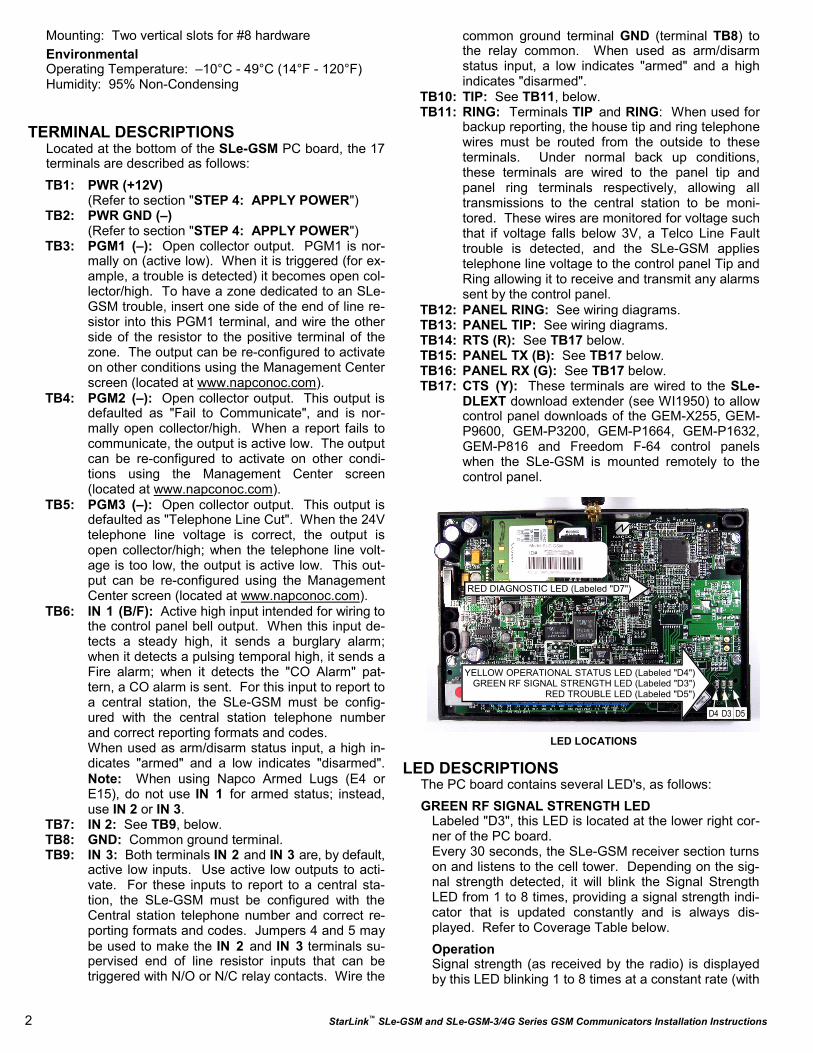
DLEXT download extender (see WI1950) to allow control panel downloads of the GEM-X255, GEM-P9600, GEM-P3200, GEM-P1664, GEM-P1632, GEM-P816 and Freedom F-64 control panels when the SLe-GSM is mounted remotely to the control panel.
LED DESCRIPTIONS The PC board contains several LED's, as follows:
GREEN RF SIGNAL STRENGTH LED Labeled "D3", this LED is located at the lower right cor-
ner of the PC board. Every 30 seconds, the SLe-GSM receiver section turns
on and listens to the cell tower. Depending on the sig-nal strength detected, it will blink the Signal Strength LED from 1 to 8 times, providing a signal strength indi-cator that is updated constantly and is always dis-played. Refer to Coverage Table below.
Operation Signal strength (as received by the radio) is displayed
by this LED blinking 1 to 8 times at a constant rate (with
LED LOCATIONS
RED DIAGNOSTIC LED (Labeled "D7")
YELLOW OPERATIONAL STATUS LED (Labeled "D4") GREEN RF SIGNAL STRENGTH LED (Labeled "D3")
RED TROUBLE LED (Labeled "D5")
D4 D3 D5
StarLink™ SLe-GSM and SLe-GSM-3/4G Series GSM Communicators Installation Instructions 3
a short delay between blink cycles). Acceptable power level is greater than or equal to -91dBm (minimum 4 blinks at the mounting location).
YELLOW OPERATIONAL STATUS LED Labeled "D4", this LED is located at the bottom right
of the PC board. Operation is as follows:
Normal Standby Condition: • Blinks on momentarily every 10 seconds: Unit is
in standby waiting for an alarm to report. Processing Alarm Conditions: • When processing an alarm, this LED will blink varia-
bly during each part of the process (dialing, hand-shaking, data transmission, etc).
RED TROUBLE LED Labeled "D5", this LED is located at the bottom right
of the PC board. Operation is as follows: • 1 Blink: Low Aux Power input voltage • 2 Blinks: Battery trouble • 3 Blinks: Alarm report Failed to Communicate • 4 Blinks: RF trouble (antenna connection or cellu-
lar registration) • 5 Blinks: Network trouble (signal unable to reach
the SLe Control Center) • 6 Blinks: Unit disabled (reporting or control panel
downloading not allowed) • 7 Blinks: Unit was shutdown and has no function-
ality; requires a restart (full power down and full power up sequence) to restore operation
• 8 Blinks: Telco Line Cut
RED DIAGNOSTIC LED Labeled "D7", this LED is located in the middle of the
PC board. One blink indicates a weak or non-existent signal from the network (green LED is off). If this red LED is blinking in any other manner, please contact technical support.
SUPPLYING POWER Control panels can provide power through their Auxiliary
Power terminals if the available standby current is re-duced by 65mA. When there is insufficient standby cur-rent due to the application (such as when 24-hour standby time is required for Residential Fire), the SLe-SMTCHG Smart Charge Module accessory must be used to charge an additional battery and to supply the standby current for the SLe-GSM.
JUMPER DESCRIPTIONS Jumper block labeled "X5"; from top to bottom, as de-
tailed in the following table:
PRIMARY AND BACK-UP REPORTING The SLe-GSM can function as a primary wireless com-
municator, in cases where there are no telephone lines present, when connected directly to the control panel Telco terminals. For primary reporting, do NOT install jumper 3 in terminal block "X5". The SLe-GSM can also function as a backup to the existing telephone lines (install jumper 3 in terminal block "X5"). When used as a backup communicator and when it senses telephone line trouble, the SLe-GSM automatically switches the communication channel from the tele-phone line to the GPRS network. See the following table for the maximum number of retry attempts.
NETWORK COVERAGE The SLe-GSM radio constantly supervises the GPRS
network coverage. When the SLe-GSM is configured for primary reporting, and the SLe-GSM detects a loss in network coverage, the SLe-GSM can be configured to prompt the control panel to announce a Telco Line Cut failure trouble using the Management Center screen (located at www.napconoc.com). Note: This Telco Line Cut failure trouble will NOT activate when the SLe-GSM is configured for backup reporting.
By default, the SLe-GSM is NOT configured to cause a Telco Line Cut failure trouble, and will NOT annunci-ate at the system keypad(s).
INSTALLATION STEPS
STEP 1: ACCOUNT REGISTRATION Create a new account and register specific SLe-GSM
modules at www.NapcoComNet.com. Accounts and modules registered via the Internet are enabled for acti-vation within 24 hours.
STEP 2: SELECT A MOUNTING LOCATION
The mounting location should be selected based on RF
Jumper Block "X5" Options Jumper block labeled "X5" contains 5 jumper terminals; from top
(labeled "1") to bottom (labeled "5") as follows:
Jumper ON Jumper Number Jumper OFF
(Not Used) 1 (Not Used)
4/2 with Checksum Pulse Format 2 4/2 Pulse Format
Backup Mode 3 Primary Mode
10K EOLR Required 4 No EOLR for Zone 3
10K EOLR Required 5 No EOLR for Zone 2
NOC Telephone #
Max # of Retry
Attempts Comments
Primary 3 Primary central station telephone number used
Backup 6 Backup central station telephone number used
GREEN RF SIGNAL STRENGTH LED RADIO RECEIVER COVERAGE TABLE
LED Blinks 8 7 6 5 4 3 2 1
-55 -65 -75 -85 -91 -95 -99 -105
S t r o n g e r S t r o n g e r S t r o n g e r · · · · · · · · · · · · · · · · · · · · · W e a k e rW e a k e rW e a k e r
Power (dBm)

4 StarLink™ SLe-GSM and SLe-GSM-3/4G Series GSM Communicators Installation Instructions
performance and ambient climate conditions. It is HIGHLY recommended that the installer carefully ad-here to the following recommendations BEFORE any wires are installed.
• Generally, high locations are best. DO NOT mount radio in basements or below grade as unpredictable performance may result.
• Whenever possible, DO NOT mount the SLe-GSM in non-climate controlled environments (i.e. attics may become extremely hot in summer, garages may become extremely cold in winter).
• Avoid mounting locations within 3 feet of AC power lines, fluorescent light fixtures, or large metal objects (air conditioners, metal garage doors, etc.) as these locations have been shown to have a detrimental effect on signal strength.
• A fair amount of care may be required to mount the SLe-GSM so as to achieve an optimal RF path. The installer should spend as much time as needed to obtain the highest signal level possible.
a. Before applying power, be sure to connect the antenna. Temporarily connect power to the SLe-GSM from a fully charged 12V (4AH mini-mum) battery. DO NOT mount the SLe-GSM at this time.
b. Position the unit in the desired mounting location, with antenna oriented vertically. The signal strength is displayed by the Green "Signal Strength LED" labeled "D3" (located at the lower right corner of the PC board). GSM radio tower signal strength may fluctuate from day to day, therefore it is best to try to find a mounting loca-tion where the LED provides a minimum of 4 blinks.
c. Once a location has been selected based on sig-nal coverage, permanently secure the unit using #8 screws (not supplied) in the two mounting holes.
WARNING: To ensure user safety and to satisfy FCC RF exposure requirements, this unit must be installed so that a minimum separation distance of 60cm (24") is always maintained between the an-tenna of the transmitting device and nearby persons. Use ONLY the existing antenna supplied by SLe-GSM to comply with this warning.
STEP 3: WIRING (PRIMARY AND BACKUP MODES)
22-gauge wire may be used if mounted up to 50 feet from the control panel, and 18-gauge wire should be used for up to 100 feet. Reference the wiring diagrams further in this manual. Note: If the control panel cen-tral station receiver reporting format is "4/2 with check-sum", be sure to install jumper #2 in jumper block la-beled "X5". See the section CONTROL PANEL PRO-GRAMMING further in this manual. For Primary Mode: Remove jumper #3 in jumper block labeled "X5". The wiring between the control panel and the SLe-GSM is over five (5) wires, as follows:
• TB1: PWR (+12V)
• TB2: PWR GND (–) • TB13: PANEL TIP • TB12: PANEL RING • TB3: PGM1 (–). Normally low output wired to the
(+) of a zone dedicated to monitoring the radio status. Should be programmed on Napco control panels as Day Zone, but be programmed to sound locally and NOT activate the bell. Note: See steps "a" and "b", below.
For Backup Mode: Install jumper #3 in jumper block labeled "X5". The wir-ing between the control panel and the SLe-GSM is over seven (7) wires, as follows:
• TB1: PWR (+12V) • TB2: PWR GND (–) • TB10: TIP • TB11: RING • TB13: PANEL TIP • TB12: PANEL RING • TB3: PGM1 (–). Normally low output wired to the
(+) of a zone dedicated to monitoring the radio status. Should be programmed on Napco control panels as Day Zone, but be programmed to sound locally and NOT activate the bell.
a. Without applying power (voltage), connect to screw terminals TB1 (+12V) and TB2 (–). If the Aux. Output cannot supply the necessary cur-rent, then you must use the SLe-SMTCHG Smart Charge Module accessory with additional battery (see WI1946). For wiring connections, see the wiring diagrams further in this manual.
b. Referencing the correct wiring diagram for the appropriate control panel (wiring diagrams are located further in this manual), connect the "TELCO" control panel terminals TIP and RING. Do NOT connect the SLe-GSM terminals TB10-13 to house telephone lines (RJ31X modular plug wires, etc.).
STEP 4: APPLY POWER
• The SLe-GSM requires 12VDC. It draws less than 65mA during standby, and almost 400mA during transmissions (for less than 1 second).
• Attach antenna before applying power ! STEP 5: SIGNAL VERIFICATION After triggering channels, use the SLe-GSM Signal
Verification to insure that the SLe-GSM Network has properly received the signals.
• Verify Online: To verify that the signals have been received by the SLe-GSM Network online, go to www.napconoc.com, log in with your Username and Password, enter your Company ID number and the SLe-GSM Radio Number, then click Signal Log.
IMPORTANT: Verify that the signals transmitted by the SLe-GSM have been properly received by your central station.
NOTE: This equipment has been tested and found to comply with the limits for a Class B Unintentional Ra-

StarLink™ SLe-GSM and SLe-GSM-3/4G Series GSM Communicators Installation Instructions 5
The panel can transmit to any standard central-station
receiver; confirm with the central station the options and type of receiver for each telephone number used.
Note: A receiver reporting format must be entered for each telephone number used, but each telephone number may be assigned a different format.
diator, pursuant to Part 15 of the FCC Rules. These limits are designed to provide reasonable protection against harmful interference in a residential installation. This equipment generates, uses, and can radiate radio frequency energy and, if not installed and used in ac-cordance with the Instruction Manual, may cause harm-ful interference to radio communications. However, there is no guarantee that interference will not occur in a particular installation. If this equipment does cause harmful interference to radio or television reception, which can be determined by turning the equipment off and on, the user is encouraged to try to correct the in-terference by one of more of the following measures: 1. Reorient or relocate the receiving antenna; 2. In-crease the separation between the equipment and re-ceiver; 3. Connect the equipment into an outlet on a circuit different from that to which the receiver is con-nected; 4. Consult the dealer or an experienced radio/TV technician for help.
CONTROL PANEL PROGRAMMING To program the central station receiver reporting for-
mat, use PCD-Windows Quickloader download soft-ware. Open the Digital Communications screen, Central Station Receivers tab, as shown in the fol-lowing images:
A "4/2" receiver format programming example:
If control panel reports using "4/2 with checksum", i.e.,
a pulse format is selected and the Sum-Check box is checked, be sure to install jumper #2 in jumper block labeled "X5".
A "Point ID" (also called "Contact ID") receiver format programming example:
SLe-GSM RELATED EVENT REPORT CODES (Contact ID by default)
EVENT AREA CONTACT ID PULSE
4/2 CODE ZONE # Zone 1 Fire 0 E110 990 11
Zone 1 Burg 0 E130 991 31
Zone 2 Panic 0 E120 992 22
Zone 3 Trouble 0 E300 993 F3
Low Battery/Voltage 0 E302 994 F4
Tamper Trouble 0 E341 995 F5
Line Cut 0 E352 996 F6
Reboot 0 E625 997 F7
Panic Alarm E123
Holdup Alarm E122
Medical Alarm E100
24 hour Aux. Alarm E150
24 hour Aux. Restore R150
Burg Perimeter Alarm E131
Burg Interior Alarm E132
Keypad Holdup Alarm (ambush) E121
Keypad Panic Alarm E123
Keypad Emergency Alarm E140
Opening E401
Closing R401
A.C. Trouble E301
Tel 1 Fail E351
NOC Originated Alarms
Contact ID Event Data
Sent
Pulse Format Event Code
Sent Initiated By Comments
Supervisory Fail E356 A00 Zn000 99 Automatically by NOC if fail to receive any signal from SLe-GSM within Super-visory Timeout duration.
For Auto Enroll, uses captured telephone number, Sub ID and format. For Dealer Programmed, uses entered telephone number, Sub ID and format.
Press to Send Test Signal E601 A00 Zn000 98
Manually by dealer from the Manage-ment Center Signal Log screen (located at www.napconoc.com). Sends test into CS receiver.
Same comment as above.
Press to Send Radio Test
Not Applicable Nothing sent to
CS receiver Not Applicable
Manually by dealer from the Manage-ment Center Checkins screen (located at www.napconoc.com). Sends a com-mand to the SLe-GSM to force a check-in to the NOC.
----
SIGNALS ORIGINATED AT THE NOC
6 StarLink™ SLe-GSM and SLe-GSM-3/4G Series GSM Communicators Installation Instructions
Supported alarm reporting formats include:
• Contact ID • Ademco Slow • Radionics Fast • Silent Knight Fast • Radionics Slow • Universal High Speed
CAUTION: The installer should always be certain an area code is programmed into the control panel.
Optional: If you wish the SLe-GSM to report a code and zone number (Contact ID by default) to the central sta-tion in response to a triggered input event, see the fol-lowing table:
Note: These event codes and zone numbers can be changed from the Management Center screen (located at www.napconoc.com). Upon alarm, the SLe-GSM sends an SMS message that includes the appropriate Contact ID alarm code, includ-ing the zone or user number, if applicable. The "SLe-GSM RELATED EVENT REPORT CODES " table in-cludes the most common Contact ID alarm codes:
Programming SLe-GSM Troubles The SLe-GSM can detect multiple troubles as indicated
by the "Red Trouble LED" (labeled "D5"). For these troubles to be annunciated, there are several methods, some of which are configurable at the Management Center screen (located at www.napconoc.com), as fol-lows:
• Method 1: Dedicate a panel zone to activate a trou-ble sounder when an open is detected. With Napco control panels, program a dedicated zone for Day Zone, mini-sounder on alarm and no bell on alarm. Wire the zone as indicated in the wiring diagrams at the end of this manual.
• Method 2: (Dedicated zone not required). If avail-able, program the control panel for telephone super-vision. Program the SLe-GSM using the Manage-ment Center "Advanced Features" screen (at www.napconoc.com) to enable Line Cut on all troubles. Note: Some control panels may require a different duration than the default time of 3 minutes.
• Method 3: Use PGMs programmed for the appro-priate trouble to active sounders directly.
StarLink™ SLe-GSM and SLe-GSM-3/4G Series GSM Communicators Installation Instructions 7
TELCO T300
RJ31X
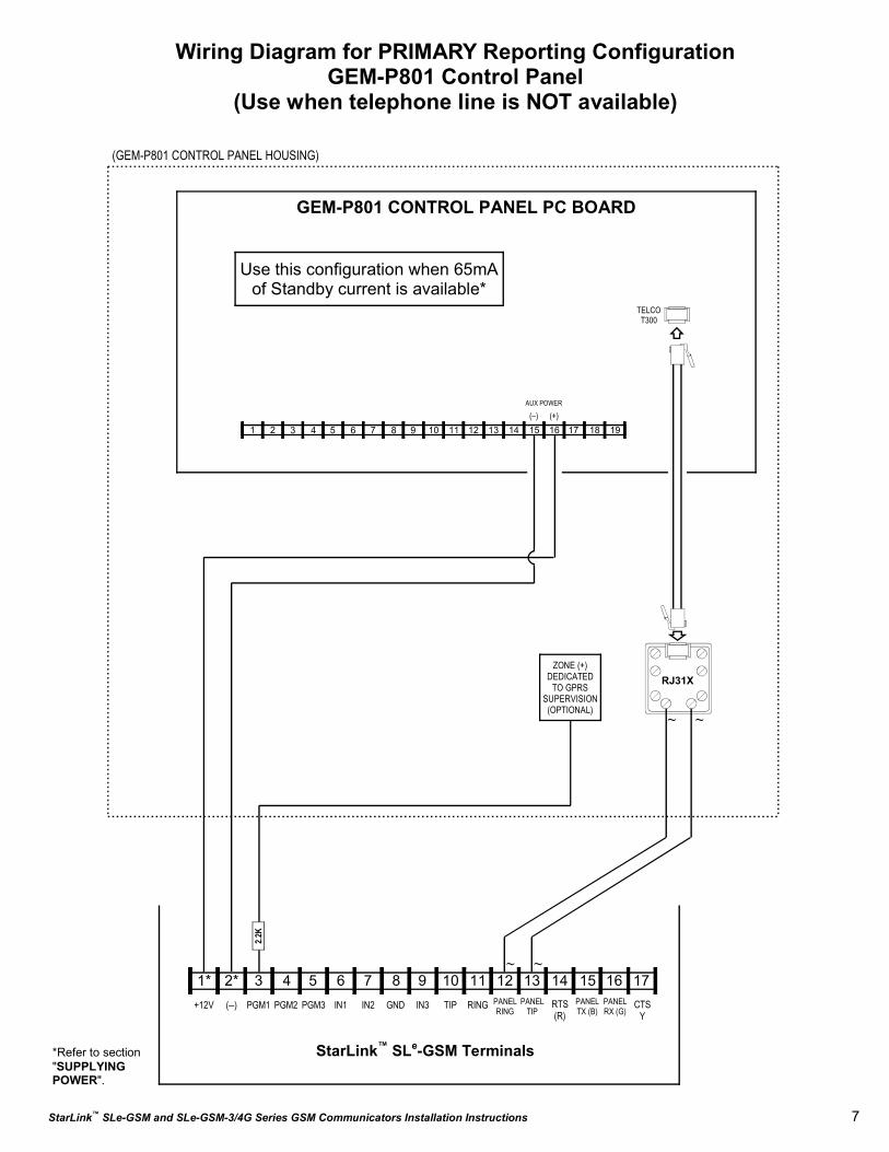
Wiring Diagram for PRIMARY Reporting Configuration GEM-P801 Control Panel
(Use when telephone line is NOT available)
GEM-P801 CONTROL PANEL PC BOARD
6 7 8 17 16 15 14 13 12 11 9 10 2 3 4 5 1 19 18
ZONE (+) DEDICATED
TO GPRS SUPERVISION (OPTIONAL)
(GEM-P801 CONTROL PANEL HOUSING)
6 7 8 15 14 13 12 11 9 10 2* 3 4 5 1* +12V (–) PGM1 PGM2 PGM3 IN1 IN2 GND IN3 RING PANEL
RING TIP
2.2K
17 16 PANEL
TIP RTS (R)
PANEL TX (B)
PANEL RX (G)
CTS Y
StarLink™ SLe-GSM Terminals
~ ~
~ ~
AUX POWER
(–) (+)
Use this configuration when 65mA of Standby current is available*
*Refer to section "SUPPLYING POWER".

8 StarLink™ SLe-GSM and SLe-GSM-3/4G Series GSM Communicators Installation Instructions
SLE-SMTCHG Smart Charge
Module
2
4
3
5
7
6
1
TELCO T300
RJ31X
Wiring Diagram for PRIMARY Reporting Configuration GEM-P801 Control Panel
(Use when telephone line is NOT available)
GEM-P801 CONTROL PANEL PC BOARD
6 7 8 17 16 15 14 13 12 11 9 10 2 3 4 5 1 19 18
ZONE (+) DEDICATED
TO GPRS SUPERVISION (OPTIONAL)
(GEM-P801 CONTROL PANEL HOUSING)
6 7 8 15 14 13 12 11 9 10 2* 3 4 5 1* +12V (–) PGM1 PGM2 PGM3 IN1 IN2 GND IN3 RING PANEL
RING TIP
2.2K
17 16 PANEL
TIP RTS (R)
PANEL TX (B)
PANEL RX (G)
CTS Y
StarLink™ SLe-GSM Terminals
~ ~
~ ~
AUX POWER
(–) (+)
16VAC
SLe-GSM BATTERY
(+) RED
(–) BLACK
16VAC Transformer
*Refer to section "SUPPLYING POWER".
Use this configuration when 65mA of Standby current is NOT available*

StarLink™ SLe-GSM and SLe-GSM-3/4G Series GSM Communicators Installation Instructions 9
Wiring Diagram for BACKUP Reporting Configuration GEM-P801 Control Panel
GEM-P801 CONTROL PANEL PC BOARD
RED
GRN
BRN GRAY
(GEM-P801 CONTROL PANEL HOUSING)
TELC
O QU
AD W
IRE
6 7 8 15 14 13 12 11 9 10 2* 3 4 5 1* +12V (–) PGM1 PGM2 PGM3 IN1 IN2 GND IN3 RING PANEL
RING TIP
2.2K
RED
GRN
YELLOW
BLACK
17 16 PANEL
TIP RTS (R)
PANEL TX (B)
PANEL RX (G)
StarLink™ SLe-GSM Terminals
6 7 8 17 16 15 14 13 12 11 9 10 2 3 4 5 1 19 18
AUX POWER
(–) (+)
16VAC
SLE-
SMTC
HG
Sm
art
Cha
rge
Mod
ule 2
4
3
5
7
6
1
SLe-GSM BATTERY
(+) RED
(–) BLACK
16VAC Transformer
ZONE (+) DEDICATED
TO GPRS SUPERVISION (OPTIONAL)
*For SLe-GSM terminals 1 and 2: May be wired directly to Aux Power of the control panel when 65mA standby current is available.
CTS Y
HOME PHONES
TO TELCO
RJ31X
TELCO T300
RJ31X
RING TIP
RING TIP
10 StarLink™ SLe-GSM and SLe-GSM-3/4G Series GSM Communicators Installation Instructions
CTS Y
Wiring Diagram for PRIMARY Reporting Configuration GEM-X255 / GEM-P9600 / GEM-P3200 Control Panels
(Use when telephone line is NOT available)
(+) (–) AUX POWER
(GEM-X255 / GEM-P9600 / GEM-P3200 CONTROL PANEL HOUSING)
6 7 8 15 14 13 12 11 9 10 2* 3 4 5 1* +12V (–) PGM1 PGM2 PGM3 IN1 IN2 GND IN3 RING PANEL
RING TIP
2.2K
17 16 PANEL
TIP RTS (R)
PANEL TX (B)
PANEL RX (G)
StarLink™ SLe-GSM Terminals
1
2
3
4
5
6
7
8
9
10
11
12 13 14 15 16 17 18 19 20 21 22 26 27 28 29 23 24 25 33 30 31 32
GEM-X255 / GEM-P9600 / GEM-P3200 Control Panel PC Board
~ ~
(un-
pola
rized
)
~ (un-polarized) ~
(un-polarized)
ZONE (+) DEDICATED
TO GPRS SUPERVISION (OPTIONAL)
*Refer to section "SUPPLYING POWER".
Use this configuration when 65mA of Standby current is available*
TIP RING TIP RING TEL LINE PHONE

StarLink™ SLe-GSM and SLe-GSM-3/4G Series GSM Communicators Installation Instructions 11
Wiring Diagram for PRIMARY Reporting Configuration GEM-X255 / GEM-P9600 / GEM-P3200 Control Panels
(Use when telephone line is NOT available)
(+) (–) AUX POWER
(GEM-X255 / GEM-P9600 / GEM-P3200 CONTROL PANEL HOUSING)
6 7 8 15 14 13 12 11 9 10 2* 3 4 5 1* +12V (–) PGM1 PGM2 PGM3 IN1 IN2 GND IN3 RING PANEL
RING TIP
2.2K
17 16 PANEL
TIP RTS (R)
PANEL TX (B)
PANEL RX (G)
StarLink™ SLe-GSM Terminals
1
2
3
4
5
6
7
8
9
10
11
12 13 14 15 16 17 18 19 20 21 22 26 27 28 29 23 24 25 33 30 31 32
GEM-X255 / GEM-P9600 / GEM-P3200 Control Panel PC Board
~ ~
(un-
pola
rized
)
~ (un-polarized) ~
(un-polarized)
SLE-SMTCHG Smart Charge
Module
2
4
3
5
7
6
1
SLe-GSM BATTERY
(+) RED
(–) BLACK
16VAC
16VAC Transformer
ZONE (+) DEDICATED
TO GPRS SUPERVISION (OPTIONAL)
*Refer to section "SUPPLYING POWER".
CTS Y
Use this configuration when 65mA of Standby current is NOT available*
TIP RING TIP RING TEL LINE PHONE

12 StarLink™ SLe-GSM and SLe-GSM-3/4G Series GSM Communicators Installation Instructions
ZONE (+) DEDICATED
TO GPRS SUPERVISION (OPTIONAL)
Wiring Diagram for BACKUP Reporting Configuration GEM-X255 / GEM-P9600 / GEM-P3200 Control Panels
(+) (–) AUX POWER
RED GRN
BRN GRAY
(GEM-X255 / GEM-P9600 / GEM-P3200 CONTROL PANEL HOUSING)
TELC
O QU
AD W
IRE
6 7 8 15 14 13 12 11 9 10 2* 3 4 5 1* +12V (–) PGM1 PGM2 PGM3 IN1 IN2 GND IN3 RING PANEL
RING TIP
2.2K
RED
GRN
YELLOW
BLACK
17 16 PANEL
TIP RTS (R)
PANEL TX (B)
PANEL RX (G)
StarLink™ SLe-GSM Terminals
1
2
3
4
5
6
7
8
9
10
11
12 13 14 15 16 17 18 19 20 21 22 26 27 28 29 23 24 25 33 30 31 32
GRAY
BRN
BLACK
YELLOW
GEM-X255 / GEM-P9600 / GEM-P3200 Control Panel PC Board 16VAC
2
4
3
5
7
6
1
SLe-GSM BATTERY
(+) RED
(–) BLACK
16VAC Transformer
*For SLe-GSM terminals 1 and 2: May be wired directly to Aux Power of the control panel when 65mA standby current is available.
SLE-
SMTC
HG
Sm
art
Cha
rge
Mod
ule
CTS Y
TIP RING TIP RING TEL LINE PHONE
HOME PHONES
TO TELCO
RJ31X
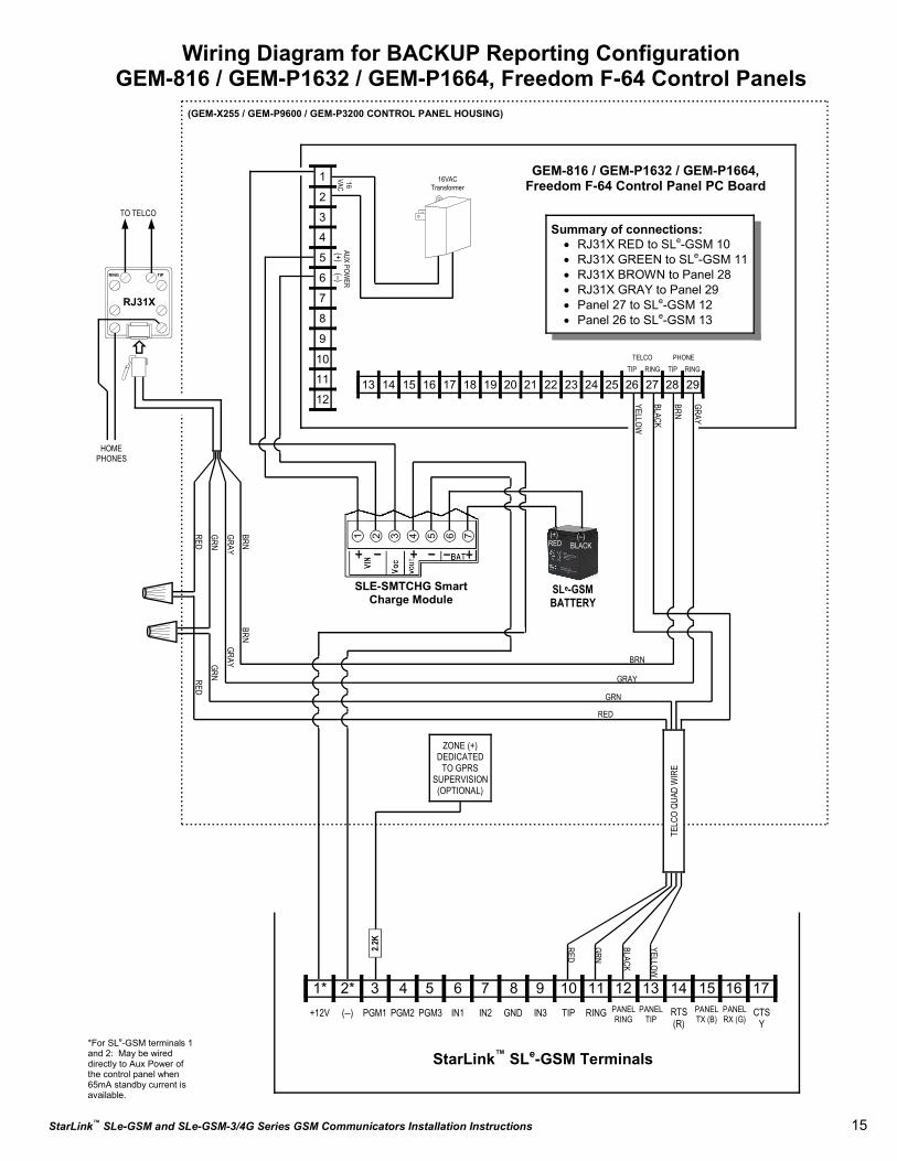
Summary of connections: • RJ31X RED to SLe-GSM 10 • RJ31X GREEN to SLe-GSM 11 • RJ31X BROWN to Panel 32 • RJ31X GRAY to Panel 33 • Panel 30 to SLe-GSM 13 • Panel 31 to SLe-GSM 12
RED
GRN RED
GRN
RING TIP

StarLink™ SLe-GSM and SLe-GSM-3/4G Series GSM Communicators Installation Instructions 13
Wiring Diagram for PRIMARY Reporting Configuration GEM-816 / GEM-P1632 / GEM-P1664, Freedom F-64 Control Panels
(Use when telephone line is NOT available)
(+) (–)
AUX POWER
(GEM-X255 / GEM-P9600 / GEM-P3200 CONTROL PANEL HOUSING)
6 7 8 15 14 13 12 11 9 10 2* 3 4 5 1* +12V (–) PGM1 PGM2 PGM3 IN1 IN2 GND IN3 RING PANEL
RING TIP
2.2K
17 16 PANEL
TIP RTS (R)
PANEL TX (B)
PANEL RX (G)
StarLink™ SLe-GSM Terminals
1
2
3
4
5
6
7
8
9
10
11
12 13 14 15 16 17 18 19 20 21 22 26 27 28 29 23 24 25
GEM-816 / GEM-P1632 / GEM-P1664, Freedom F-64 Control Panel PC Board
~ ~
~ ~
(un-
polar
ized)
(un-polarized)
(un-
polar
ized)
ZONE (+) DEDICATED
TO GPRS SUPERVISION (OPTIONAL)
*Refer to section "SUPPLYING POWER".
CTS Y
Use this configuration when 65mA of Standby current is available*
TIP RING TIP RING TELCO PHONE

14 StarLink™ SLe-GSM and SLe-GSM-3/4G Series GSM Communicators Installation Instructions
Wiring Diagram for PRIMARY Reporting Configuration GEM-816 / GEM-P1632 / GEM-P1664, Freedom F-64 Control Panels
(Use when telephone line is NOT available)
(+) (–)
AUX POWER
(GEM-X255 / GEM-P9600 / GEM-P3200 CONTROL PANEL HOUSING)
6 7 8 15 14 13 12 11 9 10 2* 3 4 5 1* +12V (–) PGM1 PGM2 PGM3 IN1 IN2 GND IN3 RING PANEL
RING TIP
2.2K
17 16 PANEL
TIP RTS (R)
PANEL TX (B)
PANEL RX (G)
StarLink™ SLe-GSM Terminals
1
2
3
4
5
6
7
8
9
10
11
12 13 14 15 16 17 18 19 20 21 22 26 27 28 29 23 24 25
GEM-816 / GEM-P1632 / GEM-P1664, Freedom F-64 Control Panel PC Board
~ ~
~ ~
(un-
polar
ized)
(un-polarized)
(un-
polar
ized)
SLE-SMTCHG Smart Charge
Module
2
4
3
5
7
6
1
SLe-GSM BATTERY
(+) RED
(–) BLACK
16VAC
16VAC Transformer
ZONE (+) DEDICATED
TO GPRS SUPERVISION (OPTIONAL)
*Refer to section "SUPPLYING POWER".
CTS Y
Use this configuration when 65mA of Standby current is NOT available*
TIP RING TIP RING TELCO PHONE
StarLink™ SLe-GSM and SLe-GSM-3/4G Series GSM Communicators Installation Instructions 15
Wiring Diagram for BACKUP Reporting Configuration GEM-816 / GEM-P1632 / GEM-P1664, Freedom F-64 Control Panels
(+) (–)
AUX POWER
RED
GRN
BRN GRAY
(GEM-X255 / GEM-P9600 / GEM-P3200 CONTROL PANEL HOUSING)
TELC
O QU
AD W
IRE
6 7 8 15 14 13 12 11 9 10 2* 3 4 5 1* +12V (–) PGM1 PGM2 PGM3 IN1 IN2 GND IN3 RING PANEL
RING TIP
2.2K
RED
GRN
YELLOW
BLACK
17 16 PANEL
TIP RTS (R)
PANEL TX (B)
PANEL RX (G)
StarLink™ SLe-GSM Terminals
1
2
3
4
5
6
7
8
9
10
11
12 13 14 15 16 17 18 19 20 21 22 26 27 28 29 23 24 25
GRAY
BRN
BLACK
YELLOW
GEM-816 / GEM-P1632 / GEM-P1664, Freedom F-64 Control Panel PC Board
TIP RING TIP RING TELCO PHONE
SLe-GSM BATTERY
SLE-SMTCHG Smart Charge Module
2 4 3 5 7 6 1
(+) RED
(–) BLACK
16 VAC
16VAC Transformer
ZONE (+) DEDICATED
TO GPRS SUPERVISION (OPTIONAL)
*For SLe-GSM terminals 1 and 2: May be wired directly to Aux Power of the control panel when 65mA standby current is available.
HOME PHONES
TO TELCO
RJ31X
RING TIP
Summary of connections: • RJ31X RED to SLe-GSM 10 • RJ31X GREEN to SLe-GSM 11 • RJ31X BROWN to Panel 28 • RJ31X GRAY to Panel 29 • Panel 27 to SLe-GSM 12 • Panel 26 to SLe-GSM 13
CTS Y
RED
RED
GRN GRN
BRN BRN
GRAY GRAY

16 StarLink™ SLe-GSM and SLe-GSM-3/4G Series GSM Communicators Installation Instructions
NAPCO SECURITY SYSTEMS, INC. (NAPCO) warrants its products to be free from manufacturing defects in materials and workmanship for eighteen months following the date of manufacture. NAPCO will, within said period, at its option, repair or replace any product failing to operate correctly without charge to the original purchaser or user.
This warranty shall not apply to any equipment, or any part thereof, which has been repaired by others, improperly installed, improperly used, abused, altered, damaged, subjected to acts of God, or on which any serial numbers have been altered, defaced or removed. Seller will not be responsible for any dismantling or reinstallation charges.
THERE ARE NO WARRANTIES, EXPRESS OR IMPLIED, WHICH EXTEND BEYOND THE DESCRIPTION ON THE FACE HEREOF. THERE IS NO EXPRESS OR IMPLIED WARRANTY OF MERCHANTABILITY OR A WARRANTY OF FITNESS FOR A PARTICULAR PURPOSE. ADDITIONALLY, THIS WARRANTY IS IN LIEU OF ALL OTHER OBLIGATIONS OR LIABILITIES ON THE PART OF NAPCO.
Any action for breach of warranty, including but not limited to any implied warranty of merchantability, must be brought within the six months following the end of the warranty period. IN NO CASE SHALL NAPCO BE LIABLE TO ANYONE FOR ANY CONSEQUENTIAL OR INCIDENTAL DAMAGES FOR BREACH OF THIS OR ANY OTHER WARRANTY, EXPRESS OR IMPLIED, EVEN IF THE LOSS OR DAMAGE IS CAUSED BY THE SELLER'S OWN NEGLIGENCE OR FAULT.
In case of defect, contact the security professional who installed and maintains your security system. In order to exercise the warranty, the product must be returned by the security professional, shipping costs prepaid and insured to NAPCO. After repair or replacement, NAPCO assumes the cost of returning products under warranty. NAPCO shall have no obligation under this warranty, or otherwise, if the product has been repaired by others, improperly installed, improperly used, abused, altered, damaged, subjected to accident, nuisance, flood, fire or acts of God, or on which any serial numbers have been altered, defaced or removed. NAPCO will not be responsible for any dismantling, reassembly or reinstallation charges.
This warranty contains the entire warranty. It is the sole warranty and any prior agreements or representations, whether oral or written, are either merged herein or are expressly cancelled. NAPCO neither assumes, nor authorizes any other person purporting to act on its behalf to modify, to change,
or to assume for it, any other warranty or liability concerning its products.
In no event shall NAPCO be liable for an amount in excess of NAPCO's original selling price of the product, for any loss or damage, whether direct, indirect, incidental, consequential, or otherwise arising out of any failure of the product. Seller's warranty, as hereinabove set forth, shall not be enlarged, diminished or affected by and no obligation or liability shall arise or grow out of Seller's rendering of technical advice or service in connection with Buyer's order of the goods furnished hereunder.
NAPCO RECOMMENDS THAT THE ENTIRE SYSTEM BE COMPLETELY TESTED WEEKLY.
Warning: Despite frequent testing, and due to, but not limited to, any or all of the following; criminal tampering, electrical or communications disruption, it is possible for the system to fail to perform as expected. NAPCO does not represent that the product/system may not be compromised or circumvented; or that the product or system will prevent any personal injury or property loss by burglary, robbery, fire or otherwise; nor that the product or system will in all cases provide adequate warning or protection. A properly installed and maintained alarm may only reduce risk of burglary, robbery, fire or otherwise but it is not insurance or a guarantee that these events will not occur. CONSEQUENTLY, SELLER SHALL HAVE NO LIABILITY FOR ANY PERSONAL INJURY, PROPERTY DAMAGE, OR OTHER LOSS BASED ON A CLAIM THE PRODUCT FAILED TO GIVE WARNING. Therefore, the installer should in turn advise the consumer to take any and all precautions for his or her safety including, but not limited to, fleeing the premises and calling police or fire department, in order to mitigate the possibilities of harm and/or damage.
NAPCO is not an insurer of either the property or safety of the user's family or employees, and limits its liability for any loss or damage including incidental or consequential damages to NAPCO's original selling price of the product regardless of the cause of such loss or damage.
Some states do not allow limitations on how long an implied warranty lasts or do not allow the exclusion or limitation of incidental or consequential damages, or differentiate in their treatment of limitations of liability for ordinary or gross negligence, so the above limitations or exclusions may not apply to you. This Warranty gives you specific legal rights and you may also have other rights which vary from state to state.
NAPCO LIMITED WARRANTY
Related Documents