starlight express OPS MANUAL 2011 V64Page 1 of 1 Pages 3/26/11 3:57 PM OPERATION MANUAL Starlight Express Bayliner 4788 Home Port Anacortes, Washington USA

Welcome message from author
This document is posted to help you gain knowledge. Please leave a comment to let me know what you think about it! Share it to your friends and learn new things together.
Transcript
starlight express OPS MANUAL 2011 V64Page 1 of 1 Pages 3/26/11 3:57 PM
OPERATION MANUAL
Starlight Express
Bayliner 4788
Home Port
Anacortes, Washington USA

Starlight Express Operation Manual
starlight express OPS MANUAL 2011 V64 Page 2 of 72 Pages Last printed 3/26/2011 3:57 PM
BLANK PAGE
Starlight Express Operation Manual
starlight express OPS MANUAL 2011 V64 Page 3 of 72 Pages Last printed 3/26/2011 3:57 PM

Starlight Express Operation Manual
starlight express OPS MANUAL 2011 V64 Page 4 of 72 Pages Last printed 3/26/2011 3:57 PM
Starlight Express Operation Manual
starlight express OPS MANUAL 2011 V64 Page 5 of 72 Pages Last printed 3/26/2011 3:57 PM
Welcome Aboard! We are happy you have chosen Starlight Express for your vacation. We are sure you will enjoy cruising to the San Juan Islands, the Gulf Islands, Puget Sound, Desolation Sound, or wherever you decide to venture. We hope this manual will help you become familiar with the boat. We ask that you keep it clean and operational. If you have questions about the boat or about places to visit, please do not hesitate to ask the AYC staff. Pleasant cruising!

Starlight Express Operation Manual
starlight express OPS MANUAL 2011 V64 Page 6 of 72 Pages Last printed 3/26/2011 3:57 PM
Starlight Express Operation Manual
starlight express OPS MANUAL 2011 V64 Page 7 of 72 Pages Last printed 3/26/2011 3:57 PM
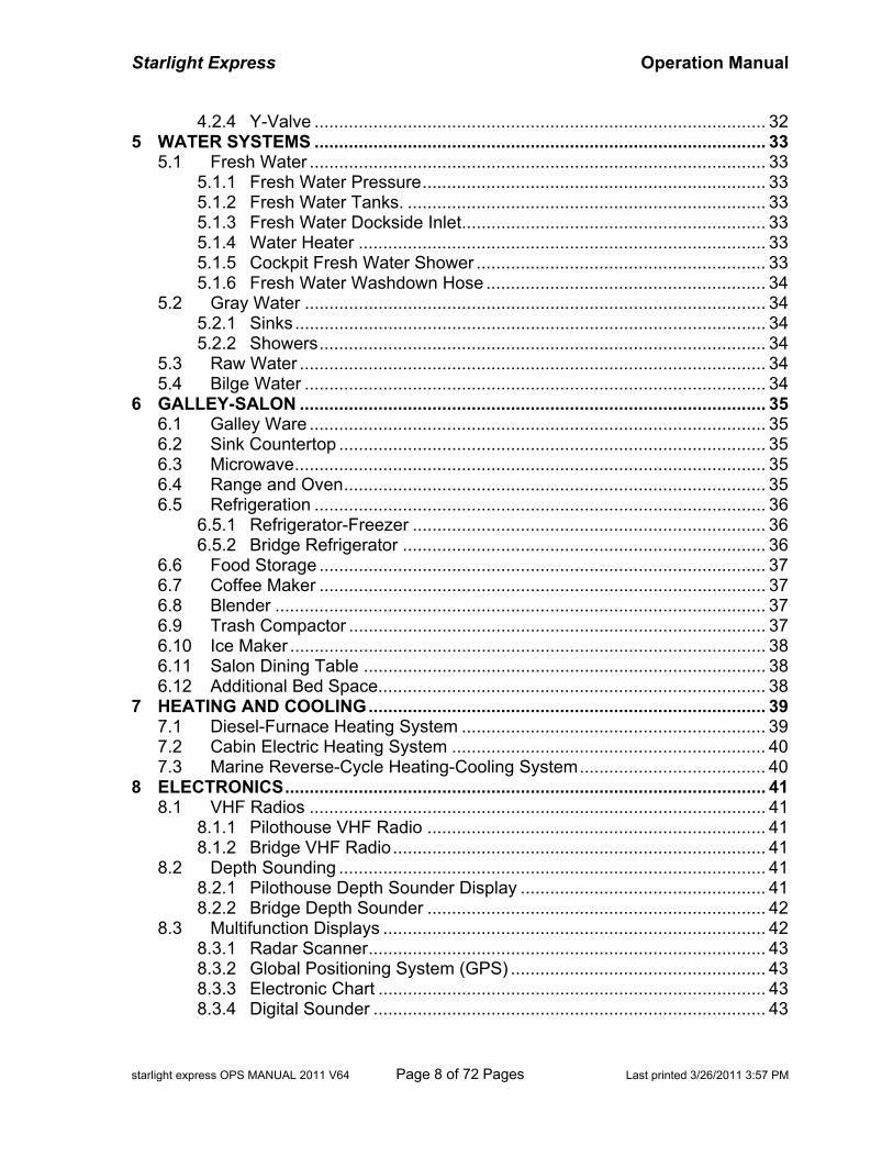
TABLE OF CONTENTS
1 BASIC INFORMATION ...................................................................................... 11 2 BOAT OPERATION ........................................................................................... 13
2.1 Important Points....................................................................................... 13 2.2 Engine Inspection .................................................................................... 13
2.2.1 Forward Engine Compartment......................................................... 13 2.2.2 Main Engine Compartment .............................................................. 14 2.2.3 Lazarette.......................................................................................... 14
2.3 Engine Startup ......................................................................................... 15 2.4 Engine Operation..................................................................................... 16 2.5 Engine Shutdown..................................................................................... 16 2.6 Getting Underway .................................................................................... 16
2.6.1 Shore Power .................................................................................... 16 2.6.2 Inside Stowage ................................................................................ 17 2.6.3 Bimini Cover .................................................................................... 17
2.7 Cruising.................................................................................................... 18 2.8 Docking.................................................................................................... 18 2.9 Fuel.......................................................................................................... 20
2.9.1 Refueling.......................................................................................... 20 2.9.2 Fuel Management............................................................................ 20
3 ELECTRICAL SYSTEMS................................................................................... 21 3.1 DC System............................................................................................... 21
3.1.1 Battery Banks and Switches ............................................................ 21 3.1.2 Panel Digital Multi-meter.................................................................. 22 3.1.3 Battery Charge Condition................................................................. 23 3.1.4 Battery Charging and Combining..................................................... 23 3.1.5 House Batteries Switch.................................................................... 24 3.1.6 Port Engine–House Battery #2 ACR................................................ 24 3.1.7 Engine Batteries Parallel Switch ...................................................... 24 3.1.8 Thruster Charger & Battery Switch .................................................. 24 3.1.9 Circuit Breakers and Fuses.............................................................. 25 3.1.10 12-Volt DC Outlets........................................................................... 25
3.2 AC System............................................................................................... 26 3.2.1 AC Sources...................................................................................... 26 3.2.2 Shore Power .................................................................................... 26 3.2.3 Generator Operation........................................................................ 27 3.2.4 Inverter Power ................................................................................. 28 3.2.5 120-volt GFCI Outlets ...................................................................... 29
4 SANITATION SYSTEM...................................................................................... 31 4.1 Marine Toilet ............................................................................................ 31 4.2 Sanitation Holding Tank........................................................................... 31
4.2.1 Sanitation Tank Warning.................................................................. 32 4.2.2 Marine Pump out Station ................................................................. 32 4.2.3 Overboard Discharge....................................................................... 32
Starlight Express Operation Manual
starlight express OPS MANUAL 2011 V64 Page 8 of 72 Pages Last printed 3/26/2011 3:57 PM
4.2.4 Y-Valve ............................................................................................ 32 5 WATER SYSTEMS ............................................................................................ 33
5.1 Fresh Water ............................................................................................. 33 5.1.1 Fresh Water Pressure...................................................................... 33 5.1.2 Fresh Water Tanks. ......................................................................... 33 5.1.3 Fresh Water Dockside Inlet.............................................................. 33 5.1.4 Water Heater ................................................................................... 33 5.1.5 Cockpit Fresh Water Shower ........................................................... 33 5.1.6 Fresh Water Washdown Hose ......................................................... 34
5.2 Gray Water .............................................................................................. 34 5.2.1 Sinks................................................................................................ 34 5.2.2 Showers........................................................................................... 34
5.3 Raw Water ............................................................................................... 34 5.4 Bilge Water .............................................................................................. 34
6 GALLEY-SALON ............................................................................................... 35 6.1 Galley Ware ............................................................................................. 35 6.2 Sink Countertop ....................................................................................... 35 6.3 Microwave................................................................................................ 35 6.4 Range and Oven...................................................................................... 35 6.5 Refrigeration ............................................................................................ 36
6.5.1 Refrigerator-Freezer ........................................................................ 36 6.5.2 Bridge Refrigerator .......................................................................... 36
6.6 Food Storage ........................................................................................... 37 6.7 Coffee Maker ........................................................................................... 37 6.8 Blender .................................................................................................... 37 6.9 Trash Compactor ..................................................................................... 37 6.10 Ice Maker ................................................................................................. 38 6.11 Salon Dining Table .................................................................................. 38 6.12 Additional Bed Space............................................................................... 38
7 HEATING AND COOLING................................................................................. 39 7.1 Diesel-Furnace Heating System .............................................................. 39 7.2 Cabin Electric Heating System ................................................................ 40 7.3 Marine Reverse-Cycle Heating-Cooling System...................................... 40
8 ELECTRONICS.................................................................................................. 41 8.1 VHF Radios ............................................................................................. 41
8.1.1 Pilothouse VHF Radio ..................................................................... 41 8.1.2 Bridge VHF Radio............................................................................ 41
8.2 Depth Sounding ....................................................................................... 41 8.2.1 Pilothouse Depth Sounder Display .................................................. 41 8.2.2 Bridge Depth Sounder ..................................................................... 42
8.3 Multifunction Displays .............................................................................. 42 8.3.1 Radar Scanner................................................................................. 43 8.3.2 Global Positioning System (GPS) .................................................... 43 8.3.3 Electronic Chart ............................................................................... 43 8.3.4 Digital Sounder ................................................................................ 43
Starlight Express Operation Manual
starlight express OPS MANUAL 2011 V64 Page 9 of 72 Pages Last printed 3/26/2011 3:57 PM
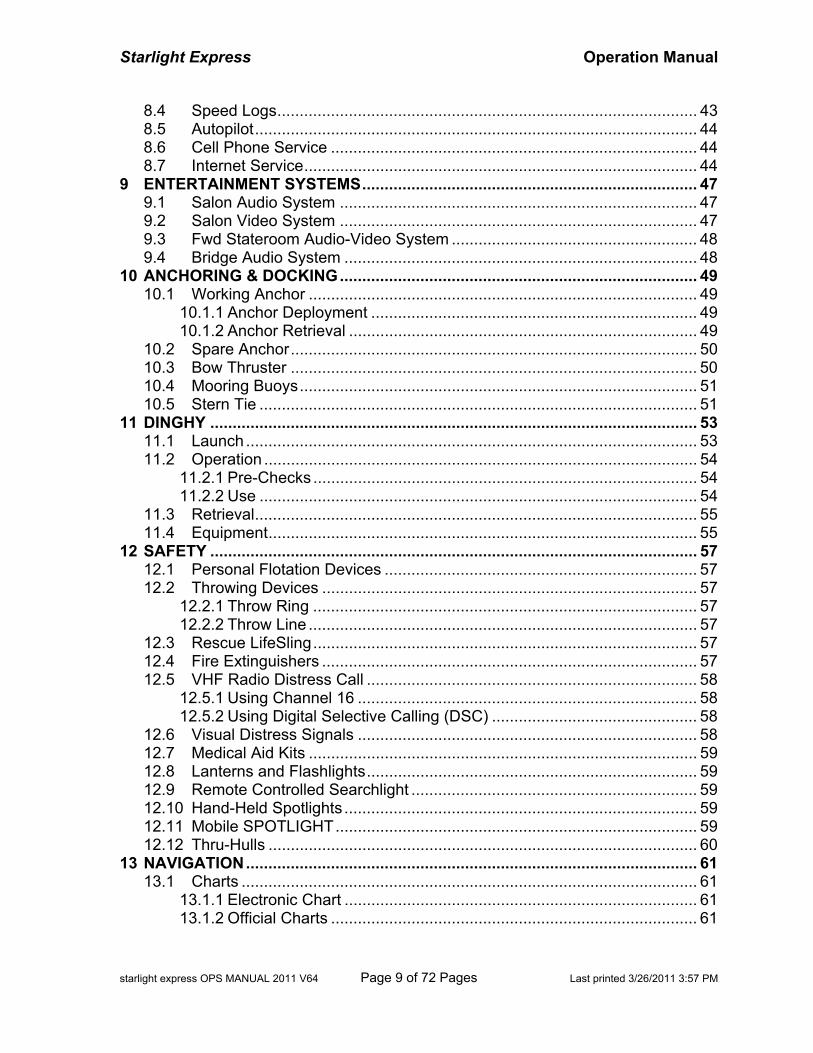
8.4 Speed Logs.............................................................................................. 43 8.5 Autopilot................................................................................................... 44 8.6 Cell Phone Service .................................................................................. 44 8.7 Internet Service........................................................................................ 44
9 ENTERTAINMENT SYSTEMS........................................................................... 47 9.1 Salon Audio System ................................................................................ 47 9.2 Salon Video System ................................................................................ 47 9.3 Fwd Stateroom Audio-Video System ....................................................... 48 9.4 Bridge Audio System ............................................................................... 48
10 ANCHORING & DOCKING................................................................................ 49 10.1 Working Anchor ....................................................................................... 49
10.1.1 Anchor Deployment ......................................................................... 49 10.1.2 Anchor Retrieval .............................................................................. 49
10.2 Spare Anchor........................................................................................... 50 10.3 Bow Thruster ........................................................................................... 50 10.4 Mooring Buoys......................................................................................... 51 10.5 Stern Tie .................................................................................................. 51
11 DINGHY ............................................................................................................. 53 11.1 Launch ..................................................................................................... 53 11.2 Operation ................................................................................................. 54
11.2.1 Pre-Checks ...................................................................................... 54 11.2.2 Use .................................................................................................. 54
11.3 Retrieval................................................................................................... 55 11.4 Equipment................................................................................................ 55
12 SAFETY ............................................................................................................. 57 12.1 Personal Flotation Devices ...................................................................... 57 12.2 Throwing Devices .................................................................................... 57
12.2.1 Throw Ring ...................................................................................... 57 12.2.2 Throw Line ....................................................................................... 57
12.3 Rescue LifeSling...................................................................................... 57 12.4 Fire Extinguishers .................................................................................... 57 12.5 VHF Radio Distress Call .......................................................................... 58
12.5.1 Using Channel 16 ............................................................................ 58 12.5.2 Using Digital Selective Calling (DSC) .............................................. 58
12.6 Visual Distress Signals ............................................................................ 58 12.7 Medical Aid Kits ....................................................................................... 59 12.8 Lanterns and Flashlights.......................................................................... 59 12.9 Remote Controlled Searchlight ................................................................ 59 12.10 Hand-Held Spotlights ............................................................................... 59 12.11 Mobile SPOTLIGHT................................................................................. 59 12.12 Thru-Hulls ................................................................................................ 60
13 NAVIGATION..................................................................................................... 61 13.1 Charts ...................................................................................................... 61
13.1.1 Electronic Chart ............................................................................... 61 13.1.2 Official Charts .................................................................................. 61
Starlight Express Operation Manual
starlight express OPS MANUAL 2011 V64 Page 10 of 72 Pages Last printed 3/26/2011 3:57 PM
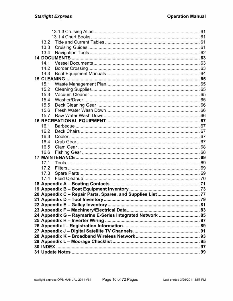
13.1.3 Cruising Atlas................................................................................... 61 13.1.4 Chart Books ..................................................................................... 61
13.2 Tide and Current Tables .......................................................................... 61 13.3 Cruising Guides ....................................................................................... 61 13.4 Navigation Tools ...................................................................................... 62
14 DOCUMENTS .................................................................................................... 63 14.1 Vessel Documents................................................................................... 63 14.2 Border Crossing....................................................................................... 63 14.3 Boat Equipment Manuals......................................................................... 64
15 CLEANING......................................................................................................... 65 15.1 Waste Management Plan......................................................................... 65 15.2 Cleaning Supplies.................................................................................... 65 15.3 Vacuum Cleaner ...................................................................................... 65 15.4 Washer/Dryer........................................................................................... 65 15.5 Deck Cleaning Gear ................................................................................ 66 15.6 Fresh Water Wash Down......................................................................... 66 15.7 Raw Water Wash Down........................................................................... 66
16 RECREATIONAL EQUIPMENT......................................................................... 67 16.1 Barbeque ................................................................................................. 67 16.2 Deck Chairs ............................................................................................. 67 16.3 Cooler ...................................................................................................... 67 16.4 Crab Gear ................................................................................................ 67 16.5 Clam Gear ............................................................................................... 68 16.6 Fishing Gear ............................................................................................ 68
17 MAINTENANCE................................................................................................. 69 17.1 Tools ........................................................................................................ 69 17.2 Filters ....................................................................................................... 69 17.3 Spare Parts.............................................................................................. 69 17.4 Fluid Cleanup........................................................................................... 70
18 Appendix A – Boating Contacts ...................................................................... 71 19 Appendix B – Boat Equipment Inventory ....................................................... 73 20 Appendix C – Repair Parts, Spares, and Supplies List ................................. 77 21 Appendix D – Tool Inventory ........................................................................... 79 22 Appendix E – Galley Inventory ........................................................................ 81 23 Appendix F – Machinery/Electrical Data......................................................... 83 24 Appendix G – Raymarine E-Series Integrated Network ................................ 85 25 Appendix H – Inverter Wiring .......................................................................... 87 26 Appendix I – Registration Information............................................................ 89 27 Appendix J – Digital Satellite TV Channels.................................................... 91 28 Appendix K – Broadband Wireless Network.................................................. 93 29 Appendix L – Moorage Checklist .................................................................... 95 30 INDEX ................................................................................................................ 97 31 Update Notes .................................................................................................... 99
Starlight Express Operation Manual
starlight express OPS MANUAL 2011 V64 Page 11 of 72 Pages Last printed 3/26/2011 3:57 PM
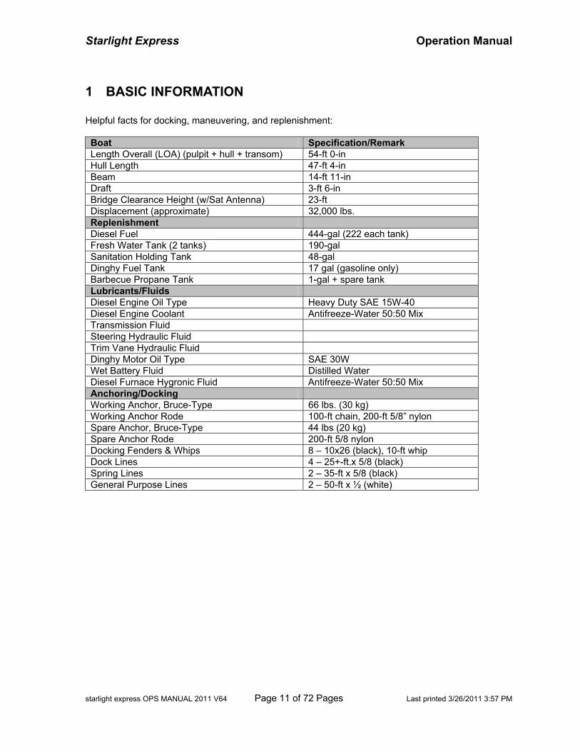
1 BASIC INFORMATION Helpful facts for docking, maneuvering, and replenishment: Boat Specification/Remark Length Overall (LOA) (pulpit + hull + transom) 54-ft 0-in Hull Length 47-ft 4-in Beam 14-ft 11-in Draft 3-ft 6-in Bridge Clearance Height (w/Sat Antenna) 23-ft Displacement (approximate) 32,000 lbs. Replenishment Diesel Fuel 444-gal (222 each tank) Fresh Water Tank (2 tanks) 190-gal Sanitation Holding Tank 48-gal Dinghy Fuel Tank 17 gal (gasoline only) Barbecue Propane Tank 1-gal + spare tank Lubricants/Fluids Diesel Engine Oil Type Heavy Duty SAE 15W-40 Diesel Engine Coolant Antifreeze-Water 50:50 Mix Transmission Fluid Steering Hydraulic Fluid Trim Vane Hydraulic Fluid Dinghy Motor Oil Type SAE 30W Wet Battery Fluid Distilled Water Diesel Furnace Hygronic Fluid Antifreeze-Water 50:50 Mix Anchoring/Docking Working Anchor, Bruce-Type 66 lbs. (30 kg) Working Anchor Rode 100-ft chain, 200-ft 5/8” nylon Spare Anchor, Bruce-Type 44 lbs (20 kg) Spare Anchor Rode 200-ft 5/8 nylon Docking Fenders & Whips 8 – 10x26 (black), 10-ft whip Dock Lines 4 – 25+-ft.x 5/8 (black) Spring Lines 2 – 35-ft x 5/8 (black) General Purpose Lines 2 – 50-ft x ½ (white)

Starlight Express Operation Manual
starlight express OPS MANUAL 2011 V64 Page 12 of 72 Pages Last printed 3/26/2011 3:57 PM
BLANK PAGE
Starlight Express Operation Manual
starlight express OPS MANUAL 2011 V64 Page 13 of 72 Pages Last printed 3/26/2011 3:57 PM
2 BOAT OPERATION Become familiar with the various systems outlined in this manual. Starlight Express has many features designed for comfort, convenience, and safety. Proper use of these features will promote a safe and relaxed trip.
2.1 Important Points • Pre-Operation. Remember “WOBBS” each morning: Water Coolant, Oil, Bilge, Belts, and Sea
Strainer. Any problem is easier to fix while moored and more difficult while adrift. • Electrical. Monitor both AC and DC electrical systems carefully. Be aware of power
consumption, available power sources, and charging capacity. Reduce use of non-essential electrical devices.
• Cruising RPM. Sustained engine speed for cruising is 2400 RPM (about 80-percent power) for
16-knots (slightly higher rpm with full fuel, water, and provision). Avoid pro-longed engine RPM above 2400, but vary the RPM. Cruising 1200 RPM can achieve 10-12 knots and will reduce fuel consumption considerably.
• Minor Repairs. Lubricants, common spare parts, and tools are located in the engine
compartment and beneath the salon portside seat (see Appendices C and D). • Protection. Protect the interior from damage - vinyl coverings, headliners, mattresses,
wallpaper, woodwork, countertops, carpet, and appliances. Protect the gel-coat surfaces.
2.2 Engine Inspection
2.2.1 Forward Engine Compartment Turn ON lights in the engine compartments at the ENGINE ROOM LIGHT switch on the Pilothouse DC Panel. Raise the passageway staircase hatch to enter the forward engine compartment. .
Fuel Management Panel. Just forward of the hatch opening, note the position of the valve levers on the FUEL MANAGEMENT PANEL. Normally, levers will be in vertical position, except the generator, which may be switched to the port fuel tank.
Primary Fuel Filters. Check the glass bowls of both PRIMARY FUEL FILTERS on the port
and starboard bulkheads for water or debris. Use a paper cup to catch the mixture. Rotate the thumb-wheel valve. Remove water and debris. Recheck frequently.
Generator and Heater Filters. On the starboard bulkhead, check the glass bowl of the
GENERATOR FUEL FILTER for water or debris. Check the glass bowl of the HEATER FUEL FILTER for water or debris. Drain as necessary.
Hydraulic Shift Reservoir. On the starboard bulkhead, check the gauge on the
HYDRAULIC SHIFT RESERVOIR. Pressure should be 80-85 PSI for best operation. A pump is located in Tools if pressure needs to be restored.
Starlight Express Operation Manual
starlight express OPS MANUAL 2011 V64 Page 14 of 72 Pages Last printed 3/26/2011 3:57 PM
Water Tank Selection. On the port bulkhead, note the position of the WATER TANK
SELECTOR valve – water is drawn from either the forward or aft water tanks located beneath the forward stateroom. If the FRESHWATER PUMP continues to run when faucets are off, the usual cause is an empty tank. Flip the selector valve to a full tank.
2.2.2 Main Engine Compartment Within the Forward Engine Compartment, remove the bulkhead hatch to the main engine compartment and stand it aside.
General Condition. Inspect each engine for abnormal condition (loose connections, leaks, etc). Check the general condition of HOSES, FUEL LINES, and AIR INTAKES.
Engine Coolant. Check the ENGINE COOLANT reservoirs – normal level is about ½ full.
Oil Level. With a paper towel or rag handy, raise the oil dipstick. A pair of etch marks on
each dipstick indicates minimum and maximum oil level. If it is necessary to add oil, raise the floorboards in the Salon to expose the top of the engine compartment. Open the oil filler cap on piston #1 valve cover. Pour oil through a funnel. Recheck the dipstick. Wipe spills.
WARNING -- DO NOT OVERFILL the engine oil. Damage may result. Recheck the oil level periodically. Record and report unusual oil consumption (or oil creation).
Transmission Fluid. Check the TRANSMISSION FLUID level in each transfer case. Raise
the dipstick on top of the transfer case housings. Replace tightly to prevent contamination.
Seacocks. Ensure the RAW WATER SEACOCK valves are in the ‘open’ position (lever in-line with valve). Check the glass container for debris. If necessary, close the seacock, loosen the thumbscrews on the cover, clean the strainer, and reassemble the cover.
CAUTION -- Open seacocks after cleaning or engine will overheat.
Bilge Pumps. Lift the center panel of the engine compartment floor. Test the automatic
bilge pump manually by lifting on the float tab switch to activate pump. If defective, take necessary steps to determine the cause -- this is the first line of defense in case of flooding.
2.2.3 Lazarette Open the center Lazarette hatch at the Cockpit.
Steering Fluid. On the transom, check the STEERING FLUID level in the container.
Trim Tab Fluid. On the transom, check the TRIM TAB FLUID level in the container.
Battery Fluid. After a week of use, check the BATTERY FLUID levels in the batteries. Ensure the water covers the metal plates. Top off with DISTILLED water.
WARNING -- Use DISTILLED WATER only – bottled water is NOT distilled water and will destroy the batteries. Do NOT overfill -- a cell is overfull when fluid covers the vented slots inside the fill opening -- there must be an air gap for bubbling gas to escape
Starlight Express Operation Manual
starlight express OPS MANUAL 2011 V64 Page 15 of 72 Pages Last printed 3/26/2011 3:57 PM
2.3 Engine Startup Use the following procedure for engine startup.
Engine Switch. At the top of the DC Electrical Panel, turn ON the PORT and STARBOARD “Engine” switches.
Trim Tab Switch. At the DC Electrical Panel lower right, turn ON the TRIM TAB switch.
Gear Shifts. At the helm station, move the GEAR SHIFTS forward and backward to check
freedom of movement. Then, position shifts to the ‘neutral’ (vertical) position -- the start-safety switch will not allow an engine start if the shift lever is not in neutral position.
Throttles. Move the THROTTLES forward and backward to check freedom of movement.
Then, position throttles to the ‘idle’ position (fully aft position).
Ignition Key. Start one engine at a time as described below. Insert key into the IGNITION SWITCHES.
Pre-Heat. Turn the key clockwise until the ENGINE ALARM sounds and ENGINE PRE-
HEAT LAMP (green) is ON. Wait for pre-heat lamp to turn OFF (alarm pitch will rise also).
Start. Turn the key fully clockwise to engage the starter motor. If the starter motor does not engage when key is turned, check neutral position of the gearshift, re-adjust, and try again.
Starting Difficulty. If the engine cranks very slowly and fails to turn over, check the
condition of the engine battery on the DC ELECTRICAL PANEL. If the battery is low, press and hold the BATTERY PARALLEL switch on the Helm Panel to combine the engine batteries, and attempt to restart engine. It may be necessary to add a slight amount of throttle for starting.
Warm-up. Raise the engine speed slowly to 800 rpm on the TACHOMETER. Warm the
engine for 2 to 4 minutes.
Gauges. Note readings on the VOLTMETER, OIL PRESSURE GAUGE, TEMPERATURE GAUGE, and FUEL GAUGE. The oil pressure should indicate at least 40 PSI within 10 seconds of start.
WARNING -- If oil pressure is low, shutdown the engine, inspect the engine compartment and find possible cause (for example, loose/leaking oil filter.)
Exhaust Water. Check the ENGINE EXHAUST on the stern to ensure cooling water is
flowing through the engine.
WARNING -- If engine overheats or there is no water expelled in the exhaust, stop the engine. Check the seacock position. Check the water strainer for debris. Check for a broken engine belt that turns the water pump. Restart the engine, and re-check for water flow at the exhaust. If water is not flowing properly, the RAW WATER PUMP may need to be serviced. Please seek assistance!
Repeat the procedure above for the other engine.
Starlight Express Operation Manual
starlight express OPS MANUAL 2011 V64 Page 16 of 72 Pages Last printed 3/26/2011 3:57 PM
2.4 Engine Operation Monitor engine operation while underway.
Oil Pressure. Check oil pressure gauges frequently. Oil pressure should remain above 40 PSI.
NOTE – The oil pressure gauge may flicker, which indicates the pressure switch may need to be replaced soon. The engine may be operated safely if the pressure flickers normal or the oil pressure warning alarm is silent.
Coolant Temperature. Coolant temperature should remain 150 and 200 degrees Fahrenheit.
WARNING -- If an engine overheats or the alarm sounds, stop the engine. Do an engine inspection to determine cause.
General Performance. Look and listen for changes in engine performance, sound, loss of RPM, or appearance that may indicate need for service. An EAR PROTECTOR is in the engine forward compartment for visual inspections while underway.
2.5 Engine Shutdown Use the following procedure for engine shutdown.
Cooling. Allow time for gradual and uniform cooling of engines. The time engaged in docking the boat is usually sufficient.
Throttles. Move each THROTTLE to the ‘idle’ (aft) position.
Ignition Key. Turn each ignition key to OFF position.
Engine Switch. At the DC Electrical Panel, turn OFF the PORT and STARBOARD “Engine”
switches.
Electronics. Check INSTRUMENT PANEL switches on Bridge and Pilothouse and turn off DC electrical devices or electronics.
2.6 Getting Underway
2.6.1 Shore Power The SHORE POWER INLETS are located on the starboard side near the pilothouse. Power cords are stowed in beneath the starboard Lazarette hatch.
Shore Power. Go to the shore station and turn the Shore Power switch OFF. Then, disconnect the cord from the shore receptacle.
CAUTION – To avoid danger of electrical shock by accidentally dropping ‘hot’ cord into the water, start with shore power end first. Disconnect, before handling cord.
Starlight Express Operation Manual
starlight express OPS MANUAL 2011 V64 Page 17 of 72 Pages Last printed 3/26/2011 3:57 PM
Boat Inlet. Disconnect the cord from the boat inlet and tighten the inlet cover.
WARNING – If the boat inlet is hot because of poor connection from burnt prongs or heat-damaged female connector, there is fire risk. Discontinue use and take steps to service. A spare 30A boat inlet and spare 30A cord connectors are in the ‘Electrical Cord Box’.
. Cord Stowage. Stow POWER CORDS beneath the starboard Lazarette hatch. Extra 30-
amp extensions cords, as well as a 50-amp cord and adapters, are stowed there also.
Adapters. Two CORD ADAPTERS (20-amp and 15-amp) are stowed inside the PILOTHOUSE AC ELECTRICAL cabinet. Use these to adapt the 30-amp power cord to 20-amp or 15-amp shore power receptacles.
To reconnect shore power, reverse the procedure above, first connecting the cord to the boat, then to the shore station.
2.6.2 Inside Stowage The following procedure is for preparing the boat interior for cruise conditions.
Portholes. Close and lock the 2 Aft Stateroom PORTHOLES, 2 Mid Stateroom PORTHOLES, Head PORTHOLES, and the 4 Forward Stateroom PORTHOLES.
Fore Deck Hatches. Close and lock the 2 deck HATHCES above the Forward Stateroom.
NOTE -- If water should soak a bunk, remove the cover and mattress and take steps to dry thoroughly, else mold and mildew will develop.
Windows. Adjust or close Salon and Pilothouse windows as desired.
Glassware. Check Galley, Salon, Stateroom, Heads, and Bridge for items that will topple or
spill while underway (drink glasses, cups, wine glasses, bowls, tall bottles, dishes, etc).
Galley. Stow dishware, glasses, pots and pans in their respective cabinets and drawers and push-in the LATCH buttons. These items tend to spill out in rough seas.
Loose Items. Put loose clothing inside CABINETS and DRAWERS and push-in the LATCH
buttons. Secure cell phones, iPods, laptops, and other items on the counters. Ensure heavy items will not move or drop.
Doors. Close or latch Stateroom and Head DOORS to prevent swinging. Secure the Bridge
HATCH door with the tie-down strap to prevent swinging shut as boat rolls.
2.6.3 Bimini Cover The BIMINI COVER may be deployed or stowed. To stow cover, release the canvas snaps from the mast. Fold the frame forward and secure the straps and frame in standing position. Wrap the BIMINI BOOT canvas around the bimini – the boot is normally stowed beneath the bridge seat portside.
Starlight Express Operation Manual
starlight express OPS MANUAL 2011 V64 Page 18 of 72 Pages Last printed 3/26/2011 3:57 PM
2.7 Cruising Operate the vessel from whichever helm provides visibility for the course, speed, weather, and sea conditions. Normally, close-quarter maneuvering is best from the bridge helm.
Line Handling. Brief crewmembers on the departure plan and assign duties for SPRING LINES, DOCK LINES, or assisting others.
Limited Visibility. Turn ON the NAVIGATION LIGHTS at the DC Panel and helm switches.
Close-Quarter Trim. Ensure the TRIM TAB switch is ON at the DC Electrical Panel. For
close quarter maneuvering, rock both TRIM TAB switches to ‘Bow-Up’ position to retract the trim vanes. This helps the boat to move freely when backing.
Bow Thruster Control. Push the two ON buttons at the BOW THRUSTER control to
activate the joystick to move the bow, as necessary.
Throttles and Gear Shifts. Ensure the THROTTLES are ‘idle’ before engaging the GEAR SHIFTS to avoid engine and transmission damage.
Fenders and Lines. After clearing dock traffic, crewmembers may stow FENDERS and
lines.
Cruising Trim. Before high-speed cruising, rock both TRIM TAB switches to ‘Bow-Down’ position (extends trim vanes downward). The raises boat’s aft as it accelerates to cruise.
Acceleration. Increase THROTTLES slowly, allowing the engines to power up. Equalize
(center) the engine speeds on the ENGINE SYNCHRONIZER on the Pilothouse helm.
Cruise RPM. Normally, ENGINE SPEED for cruising is 2400 RPM (80% of rated engine power). This should achieve a satisfactory plane, depending upon boat configuration, weight, and sea condition. Choose a lower rpm for lower fuel consumption rate. Avoid engine speeds above 2400 RPM; but, vary the speed slightly for short durations.
‘Following Sea’ Trim. In ‘following-sea’ conditions or swells, favor a ‘bow-up’ trim position to
avoid plowing into waves. Perform all trim adjustments carefully.
2.8 Docking For docking, the Bridge helm usually offers the greatest visibility all around.
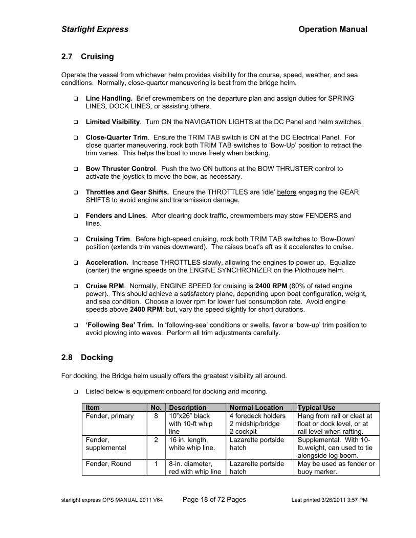
Listed below is equipment onboard for docking and mooring.
Item No. Description Normal Location Typical Use Fender, primary 8 10”x26” black
with 10-ft whip line
4 foredeck holders 2 midship/bridge 2 cockpit
Hang from rail or cleat at float or dock level, or at rail level when rafting.
Fender, supplemental
2 16 in. length, white whip line.
Lazarette portside hatch
Supplemental. With 10-lb.weight, can used to tie alongside log boom.
Fender, Round 1 8-in. diameter, red with whip line
Lazarette portside hatch
May be used as fender or buoy marker.
Starlight Express Operation Manual
starlight express OPS MANUAL 2011 V64 Page 19 of 72 Pages Last printed 3/26/2011 3:57 PM
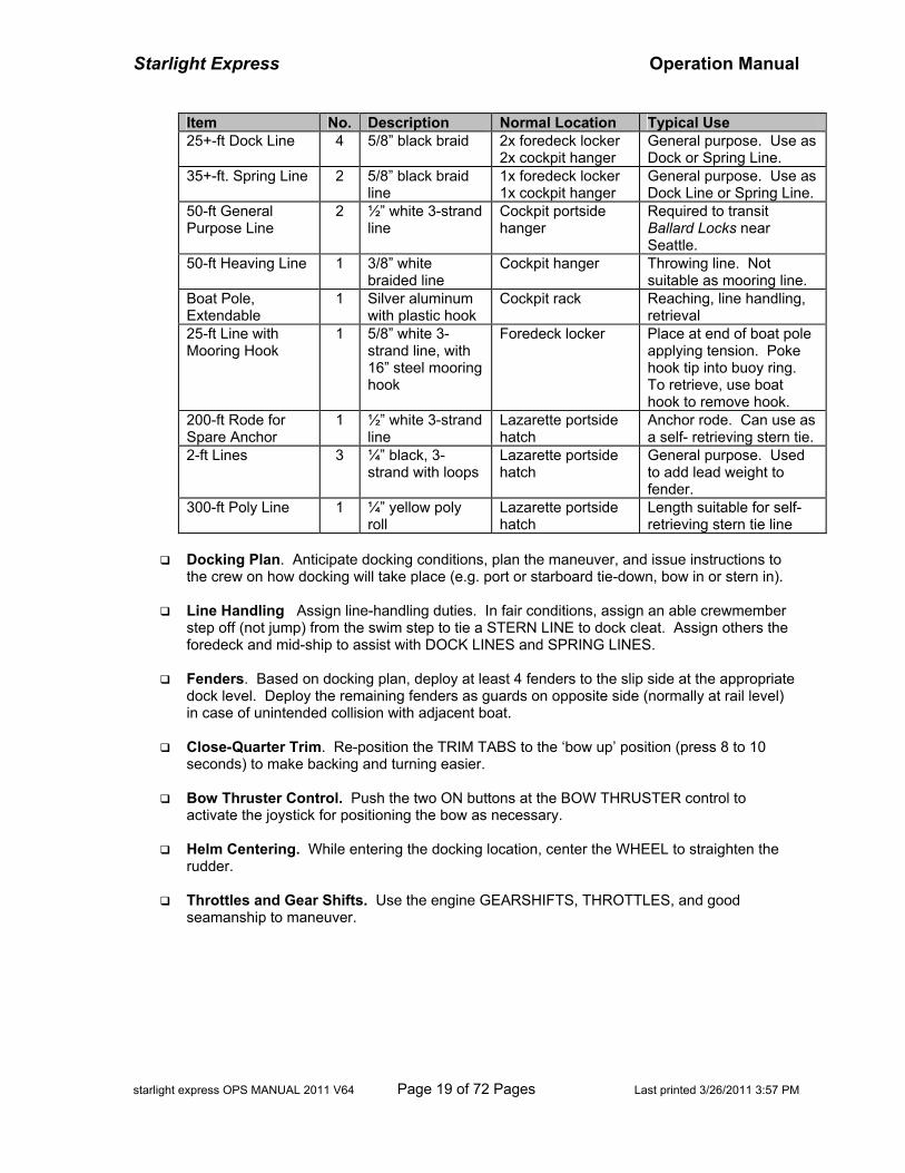
Item No. Description Normal Location Typical Use 25+-ft Dock Line 4 5/8” black braid 2x foredeck locker
2x cockpit hanger General purpose. Use as Dock or Spring Line.
35+-ft. Spring Line 2 5/8” black braid line
1x foredeck locker 1x cockpit hanger
General purpose. Use as Dock Line or Spring Line.
50-ft General Purpose Line
2 ½” white 3-strand line
Cockpit portside hanger
Required to transit Ballard Locks near Seattle.
50-ft Heaving Line 1 3/8” white braided line
Cockpit hanger Throwing line. Not suitable as mooring line.
Boat Pole, Extendable
1 Silver aluminum with plastic hook
Cockpit rack Reaching, line handling, retrieval
25-ft Line with Mooring Hook
1 5/8” white 3-strand line, with 16” steel mooring hook
Foredeck locker Place at end of boat pole applying tension. Poke hook tip into buoy ring. To retrieve, use boat hook to remove hook.
200-ft Rode for Spare Anchor
1 ½” white 3-strand line
Lazarette portside hatch
Anchor rode. Can use as a self- retrieving stern tie.
2-ft Lines 3 ¼” black, 3-strand with loops
Lazarette portside hatch
General purpose. Used to add lead weight to fender.
300-ft Poly Line 1 ¼” yellow poly roll
Lazarette portside hatch
Length suitable for self-retrieving stern tie line
Docking Plan. Anticipate docking conditions, plan the maneuver, and issue instructions to
the crew on how docking will take place (e.g. port or starboard tie-down, bow in or stern in).
Line Handling Assign line-handling duties. In fair conditions, assign an able crewmember step off (not jump) from the swim step to tie a STERN LINE to dock cleat. Assign others the foredeck and mid-ship to assist with DOCK LINES and SPRING LINES.
Fenders. Based on docking plan, deploy at least 4 fenders to the slip side at the appropriate
dock level. Deploy the remaining fenders as guards on opposite side (normally at rail level) in case of unintended collision with adjacent boat.
Close-Quarter Trim. Re-position the TRIM TABS to the ‘bow up’ position (press 8 to 10
seconds) to make backing and turning easier.
Bow Thruster Control. Push the two ON buttons at the BOW THRUSTER control to activate the joystick for positioning the bow as necessary.
Helm Centering. While entering the docking location, center the WHEEL to straighten the
rudder.
Throttles and Gear Shifts. Use the engine GEARSHIFTS, THROTTLES, and good seamanship to maneuver.
Starlight Express Operation Manual
starlight express OPS MANUAL 2011 V64 Page 20 of 72 Pages Last printed 3/26/2011 3:57 PM
2.9 Fuel
2.9.1 Refueling Each fuel tank holds 222 gallons – total 444 gallons. Turn the ignition keys ON to read the Pilothouse fuel gauges.
Estimate. Estimate the number of gallons to add to each tank based on the fuel gauge reading. For example, if fuel gauge is ¾ full, anticipate 55-gallons; if ½ full, 110-gallons; if ¼ full, 165-gallons.
NOTE -- It is good practice to refuel before the tanks reach ¼ full. The best reason is to avoid the anxiety of searching for fuel.
Fuel Filler Cap. The FUEL FILL CAP for each tank is located on the side-deck, aft of the
pilothouse doors. Fuel vents are located below the tank opening. Remove the FILLER CAP with the CAP REMOVAL TOOL.
Diesel Hose. At the pump, ensure the attendant provides the correct fuel hose: DIESEL,
DIESEL, DIESEL. Make sure the nozzle is placed into the ‘DIESEL’ deck filler opening (and not the sewage holding tank). Double-check to avoid catastrophe. Have extra oil sorbs handy to soak up spilled fuel.
NOTE – On some fuel docks, the hose length is insufficient to reach the opposite side deck fill; therefore, it may be necessary to pass the hose through the pilothouse. Please take steps to protect the carpet and interior. Reposition rugs, mats, and oil sorbs beneath the hose path. Before passing hose through the pilothouse, wrap a sorb around the nozzle to catch drips. Wipe the hose with sorbs or towels to remove fuel, grease, and dirt.
Pumping. If necessary, position a crewmember at the pump to call out number of gallons.
Place the nozzle into the tank opening. Pump slowly and evenly. Note the sound of the fuel flow. Pumping too fast may interfere with escaping air and result in a fountain of fuel spewing from the opening. As the tank fills, the sound will rise in pitch or gurgle. Pay attention to the TANK OVERFLOW VENT on the outside below the opening. Spurting may indicate the tank is full. Be prepared to catch spilled fuel from the overflow vent. Top off carefully. NOTE -- Spillage may result in a nasty fine from law enforcement.
Fuel Filler Cap. Replace each tank fill cap, but do not over-tighten. Clean spillage with oil
sorbs for environmental and health reasons. Wash hands with soap and water thoroughly.
2.9.2 Fuel Management The FUEL MANAGEMENT BOARD is located beneath the hatch opening at the front engine compartment. Fuel is directed from either tank to the engines and generator using the supply valves. Recheck the position of the valve levers each time when entering or exiting the engine compartment to ensure they are open (vertical position).
Starlight Express Operation Manual
starlight express OPS MANUAL 2011 V64 Page 21 of 72 Pages Last printed 3/26/2011 3:57 PM
3 ELECTRICAL SYSTEMS Systems. The boat electrical system is organized into TWO power distribution systems:
• DC (Direct Current) – 12V boat systems, lights, and electronics. • AC (Alternating Current) – 120V appliances, similar to household use
DC Sources. The DC power distribution system has six sources:
• House Battery Bank #1 - main boat systems, lights, and electronics • House Battery Bank #2 – AC devices connected to inverter, as well as DC components • Starboard Engine Battery – Starboard Engine starting • Port Engine Battery – Port Engine starting • Generator Battery – Diesel Generator starting • Thruster Battery (24V) – Bow Thruster operation
AC Sources. The AC power distribution system has three sources:
• Shore power – connected to all AC systems • 12 kilowatt Diesel generator – connected to all AC systems • DC-AC Inverter – connected to ‘selected’ AC systems (see section ‘Inverter Power’)
The boat electrical components are controlled at the Pilothouse AC and DC ELECTRICAL PANELS, the BATTERY SWITCH PANEL in the Salon aft port cabinet, and the Thruster BATTERY switch in the Forward Stateroom. When AC Shore Power or the Generator is not used, the DC batteries provided 12-volt DC power and ‘inverted’ 120-volt AC power. Batteries have limited capacity. Monitor the use of DC electricity carefully. Turn OFF unnecessary electrical devices to conserve battery power. Shore Power, generator, or engine alternators restore battery capacity through charging devices. AC and DC Panel breakers are labeled for all devices and circuits.
3.1 DC System
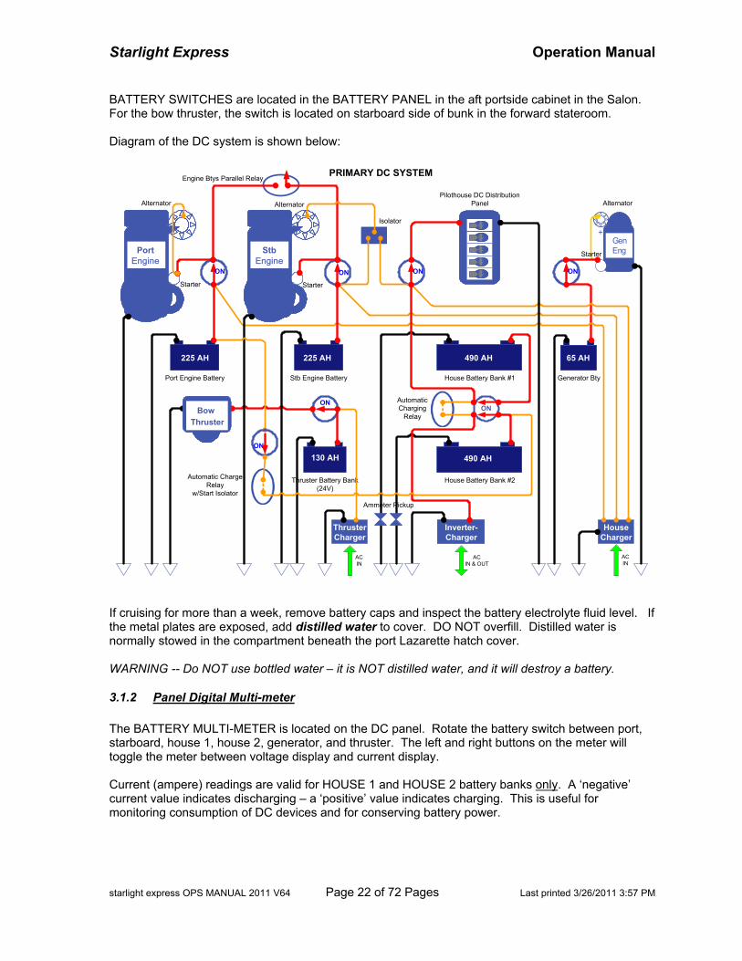
3.1.1 Battery Banks and Switches The BATTERY BANKS supply power for DC lights, electronics, engine starting, generator starting, and bow thruster. There are six battery banks:
Battery or Battery Bank Battery Type Fully Charged Capacity Port Engine Battery SeaVolt Group 8D (wet cell) 255-AH Starboard Engine Battery SeaVolt Group 8D (wet cell) 255-AH House Battery Bank #1 boat system Trojan T105 (4x6V 2-Pair, Deep-Cycle) 450-AH House Battery Bank #2 inverter Dyno GC2B (4x6V 2-Pair, Deep-Cycle) 490-AH Generator Battery SeaVolt Group 24 650CCA (wet cell) 65-AH Thruster Battery Bank (24V) Optima Glasmat (2x12V, DeepC, dry) 130-AH
Battery power consumption is measured in ampere per hour (AH or amp-hr). For example, a DC device consuming 10-amps for 10 hours would use 100-AH (#amperes multiplied by #hours equals #amp-hrs). Note - The DC lights in the salon alone consume 10+ Amps -- use DC devices wisely.
Starlight Express Operation Manual
starlight express OPS MANUAL 2011 V64 Page 22 of 72 Pages Last printed 3/26/2011 3:57 PM
BATTERY SWITCHES are located in the BATTERY PANEL in the aft portside cabinet in the Salon. For the bow thruster, the switch is located on starboard side of bunk in the forward stateroom. Diagram of the DC system is shown below:
Thruster Battery Bank(24V)
1515
15
15
15
151515151515
151515
151515
151515
+GenEng
House Battery Bank #1
Inverter-Charger
Stb Engine Battery Generator Bty
House Battery Bank #2
PortEngine
StbEngine
Port Engine Battery
ON
HouseCharger
ThrusterCharger
ACIN & OUT
ACIN
ACIN
490 AH
490 AH
225 AH225 AH
130 AH
ON
ONON ONON
Engine Btys Parallel Relay
AutomaticCharging
Relay
Alternator
Starter Starter
Alternator Alternator
Starter
Pilothouse DC DistributionPanel
Isolator
65 AH
Automatic ChargeRelay
w/Start Isolator
Ammeter Pickup
PRIMARY DC SYSTEM
BowThruster
ON
If cruising for more than a week, remove battery caps and inspect the battery electrolyte fluid level. If the metal plates are exposed, add distilled water to cover. DO NOT overfill. Distilled water is normally stowed in the compartment beneath the port Lazarette hatch cover. WARNING -- Do NOT use bottled water – it is NOT distilled water, and it will destroy a battery.
3.1.2 Panel Digital Multi-meter The BATTERY MULTI-METER is located on the DC panel. Rotate the battery switch between port, starboard, house 1, house 2, generator, and thruster. The left and right buttons on the meter will toggle the meter between voltage display and current display. Current (ampere) readings are valid for HOUSE 1 and HOUSE 2 battery banks only. A ‘negative’ current value indicates discharging – a ‘positive’ value indicates charging. This is useful for monitoring consumption of DC devices and for conserving battery power.
Starlight Express Operation Manual
starlight express OPS MANUAL 2011 V64 Page 23 of 72 Pages Last printed 3/26/2011 3:57 PM
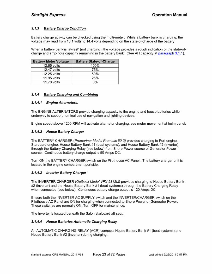
3.1.3 Battery Charge Condition Battery charge activity can be checked using the multi-meter. While a battery bank is charging, the voltage may read from 13.1 volts to 14.4 volts depending on the state-of-charge of the battery. When a battery bank is ‘at-rest’ (not charging), the voltage provides a rough indication of the state-of-charge and amp-hour capacity remaining in the battery bank. (See AH capacity at paragraph 3.1.1).
Battery Meter Voltage Battery State-of-Charge
12.65 volts 100% 12.47 volts 75% 12.25 volts 50% 11.95 volts 25% 11.70 volts 0%
3.1.4 Battery Charging and Combining
3.1.4.1 Engine Alternators. The ENGINE ALTERNATORS provide charging capacity to the engine and house batteries while underway to support nominal use of navigation and lighting devices. Engine speed above 1200 RPM will activate alternator charging; see meter movement at helm panel.
3.1.4.2 House Battery Charger The BATTERY CHARGER (Promariner Model Promatic 50-3) provides charging to Port engine, Starboard engine, House Battery Bank #1 (boat systems), and House Battery Bank #2 (inverter) through the Battery Charging Relay (see below) from Shore Power source or Generator Power source. Continuous battery charge output is 50 Amps DC. Turn ON the BATTERY CHARGER switch on the Pilothouse AC Panel. The battery charger unit is located in the engine compartment portside.
3.1.4.3 Inverter Battery Charger The INVERTER CHARGER (Outback Model VFX-2812M) provides charging to House Battery Bank #2 (inverter) and the House Battery Bank #1 (boat systems) through the Battery Charging Relay when connected (see below). Continuous battery charge output is 120 Amps DC. Ensure both the INVERTER AC SUPPLY switch and the INVERTER/CHARGER switch on the Pilothouse AC Panel are ON for charging when connected to Shore Power or Generator Power. These switches are normally ON. Turn OFF for maintenance. The Inverter is located beneath the Salon starboard aft seat.
3.1.4.4 House Batteries Automatic Charging Relay An AUTOMATIC CHARGING RELAY (ACR) connects House Battery Bank #1 (boat systems) and House Battery Bank #2 (inverter) during charging.
Starlight Express Operation Manual
starlight express OPS MANUAL 2011 V64 Page 24 of 72 Pages Last printed 3/26/2011 3:57 PM
When no charging source is present, the relay disconnects the banks to conserve storage. For example if House Battery Bank #2 (inverter) is discharged heavily, the ACR will disconnect to isolate House Battery Bank #1. Three LED indicators show the following:
• GREEN – Bank #1 and Bank #2 connected. If charge voltage to a bank is high, the LED will turn ON and connect the other bank in about 1 minute for charging.
• AMBER – Either bank is being discharged. When the LED turns ON, the battery banks will disconnect in about 1 minute.
• RED – Over-voltage (above 15-volts). The RED LED will turn ON, and the relay will disconnect battery banks.
NOTE -- The ACR is bypassed when the adjacent House Batteries Switch is in Battery ‘Combine’ position. (See section House Batteries Switch)
3.1.5 House Batteries Switch The switch is located forward of the generator next to the house battery-automatic charging relay ACR. When in ON position, the HOUSE BATTERIES SWITCH connects the House Battery Bank #1 to boat systems components and the House Battery Bank #2 to DC inverter components. When in the OFF position, both battery banks are disconnected from DC system. In exceptional cases, both House Battery Banks can be combined (for example, to carry an ailing battery bank or a failing charger). Turn the switch to the COMBINE position. CAUTION – If one bank is severely discharged, a large current transfer will occur across the switch.
3.1.6 Port Engine–House Battery #2 ACR To supplement charging while underway, an AUTOMATIC CHARGING RELAY (ACR) connects the House Battery Bank #2 (inverter) to the Port Engine alternator (via the port engine battery) When port alternator is not operating, the relay disconnects to isolate the Port Engine Battery and House Battery Bank #2. Also, the port alternator is disconnected during engine cranking (‘start isolation’) to avoid voltage spikes into the House DC system. NOTE -- The adjacent Battery Switch controls the circuit – it is in the ON position normally. Turn OFF when maintaining either battery/battery bank.
3.1.7 Engine Batteries Parallel Switch An ENGINE BATTERIES PARALLEL switch is provided at the pilothouse helm. It will combine STARBOARD ENGINE BATTERY and PORT ENGINE BATTERY in situation where an engine battery is too weak to start its engine.
3.1.8 Thruster Charger & Battery Switch The THRUSTER BATTERY CHARGER (Xantrex Model XC 1524) provides charging to the Bow Thruster Battery Bank.
Starlight Express Operation Manual
starlight express OPS MANUAL 2011 V64 Page 25 of 72 Pages Last printed 3/26/2011 3:57 PM
Turn ON the BT BATTERY CHARGER switch on the Pilothouse AC Panel. The battery charger is located beneath the forward stateroom bunk, starboard side. NOTE - The thruster battery bank has a dedicated 24-V charger connected to shore power or generator (AC sources). It DOES NOT connect to the inverter-charger or engine alternators for DC charging. The THRUSTER BATTERY SWITCH is located on the starboard side of the forward stateroom bunk. Normally this switch is in the ON position for bow thruster operation. Turn OFF the switch to disconnect the battery during emergency or maintenance.
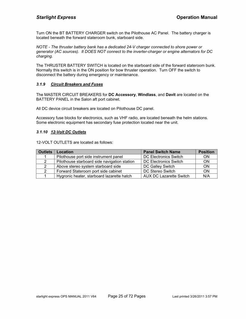
3.1.9 Circuit Breakers and Fuses The MASTER CIRCUIT BREAKERS for DC Accessory, Windlass, and Davit are located on the BATTERY PANEL in the Salon aft port cabinet. All DC device circuit breakers are located on Pilothouse DC panel. Accessory fuse blocks for electronics, such as VHF radio, are located beneath the helm stations. Some electronic equipment has secondary fuse protection located near the unit.
3.1.10 12-Volt DC Outlets 12-VOLT OUTLETS are located as follows:
Outlets Location Panel Switch Name Position
1 Pilothouse port side instrument panel DC Electronics Switch ON 2 Pilothouse starboard side navigation station DC Electronics Switch ON 2 Above stereo system starboard side DC Galley Switch ON 2 Forward Stateroom port side cabinet DC Stereo Switch ON 1 Hygronic heater, starboard lazarette hatch AUX DC Lazarette Switch N/A
Starlight Express Operation Manual
starlight express OPS MANUAL 2011 V64 Page 26 of 72 Pages Last printed 3/26/2011 3:57 PM
3.2 AC System
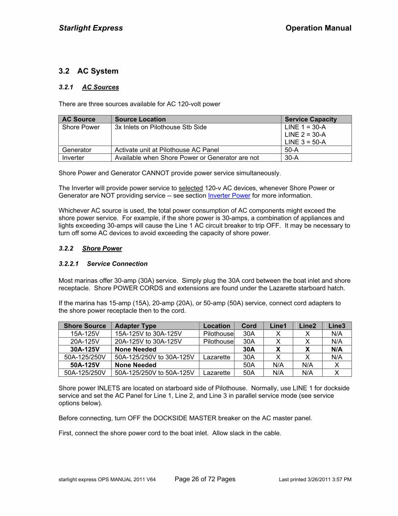
3.2.1 AC Sources There are three sources available for AC 120-volt power AC Source Source Location Service Capacity Shore Power 3x Inlets on Pilothouse Stb Side LINE 1 = 30-A
LINE 2 = 30-A LINE 3 = 50-A
Generator Activate unit at Pilothouse AC Panel 50-A Inverter Available when Shore Power or Generator are not 30-A
Shore Power and Generator CANNOT provide power service simultaneously. The Inverter will provide power service to selected 120-v AC devices, whenever Shore Power or Generator are NOT providing service -- see section Inverter Power for more information. Whichever AC source is used, the total power consumption of AC components might exceed the shore power service. For example, if the shore power is 30-amps, a combination of appliances and lights exceeding 30-amps will cause the Line 1 AC circuit breaker to trip OFF. It may be necessary to turn off some AC devices to avoid exceeding the capacity of shore power.
3.2.2 Shore Power
3.2.2.1 Service Connection Most marinas offer 30-amp (30A) service. Simply plug the 30A cord between the boat inlet and shore receptacle. Shore POWER CORDS and extensions are found under the Lazarette starboard hatch. If the marina has 15-amp (15A), 20-amp (20A), or 50-amp (50A) service, connect cord adapters to the shore power receptacle then to the cord.
Shore Source Adapter Type Location Cord Line1 Line2 Line3 15A-125V 15A-125V to 30A-125V Pilothouse 30A X X N/A 20A-125V 20A-125V to 30A-125V Pilothouse 30A X X N/A 30A-125V None Needed 30A X X N/A
50A-125/250V 50A-125/250V to 30A-125V Lazarette 30A X X N/A 50A-125V None Needed 50A N/A N/A X
50A-125/250V 50A-125/250V to 50A-125V Lazarette 50A N/A N/A X Shore power INLETS are located on starboard side of Pilothouse. Normally, use LINE 1 for dockside service and set the AC Panel for Line 1, Line 2, and Line 3 in parallel service mode (see service options below). Before connecting, turn OFF the DOCKSIDE MASTER breaker on the AC master panel. First, connect the shore power cord to the boat inlet. Allow slack in the cable.
Starlight Express Operation Manual
starlight express OPS MANUAL 2011 V64 Page 27 of 72 Pages Last printed 3/26/2011 3:57 PM
Next, turn OFF the switch on the shore power receptacle. Then, connect the cord to the receptacle. Finally, turn ON the shore power receptacle. CAUTION -- Always attach the shore power cord to the boat inlet first, then to dockside service last, to avoid shock or injury by accidental drop of “hot” cord into the water. Move power cord off pathways and shield from foot traffic. Coil excess cordage. Hang cord securely if over water. Turn ON the DOCKSIDE MASTER switch. The VOLTMETER will read 110 to 120-volts. WARNING -- Check the electrical panel polarity indicator. A “red” light indicates reverse polarity and is dangerous – DO NOT engage the DOCKSIDE MASTER breaker switch. Immediately turn OFF the shore power source, disconnect cord, and notify dock or marina management. Turn ON individual AC component breakers, as required. If the dockside power capacity is exceeded, the breaker will trip. Reduce or turn off excess AC devices before resetting the breaker.
3.2.2.2 Service Line Options Normally, LINE 2 and LINE 3 on the Pilothouse AC Panel are operating in “parallel’ mode with LINE 1. “Parallel mode” is setup when LINE 2 selector switch points to ‘Line 1-2’ and LINE 3 Selector switch points to ‘Line 1-3”. The MASTER breakers for Lines 2 and 3 are disabled. In “parallel” mode, total current value is the sum of the three AMMETER values. If the total value current exceeds the capacity of shore power service, the LINE1 DOCKSIDE MASTER breaker will trip. Reduce AC components to not exceed the service capacity If additional shore power service is desired and available, LINE 2 and/or LINE 3 can be switched to “normal” mode to deliver power to their respective AC lines, increasing total power to the boat. In “normal” mode, the current is read on each line’s AMMETER. NOTE -- The most common use, and the easiest to control, is “parallel” mode.
3.2.3 Generator Operation The Westerbeke diesel-powered GENERATOR is located beneath the Lazarette center hatch. Before operating the generator, ensure the generator SEACOCK is OPEN and the strainer is clear of debris. Check the oil level dipstick periodically. Check the coolant level inside the portside cockpit locker. Close the sound enclosure.
The GENERATOR CONTROL is located on the Pilothouse AC panel. To start the generator, rotate the GENERATOR CONTROL knob to RUN position. Press and hold the PRE-HEAT/OVERRIDE switch for about 15-seconds to pre-heat generator. Then, while still pressing the pre-heat switch, rotate the CONTROL knob to the START position, releasing the control knob as the generator starts. About 5-seconds later, release the pre-heat switch. Do not operate the starter for more than 15 seconds. If the generator does not start, wait at least 30 seconds, repeat steps above, and then attempt another start. NOTE -- The starting solenoid has been known to stick when the PRE-HEAT/OVERRIDE switch is pressed. To check the condition of the solenoid, open the generator enclosure and locate the solenoid arm at the front starboard side of generator. Have an assistant push the PRE-HEAT switch
Starlight Express Operation Manual
starlight express OPS MANUAL 2011 V64 Page 28 of 72 Pages Last printed 3/26/2011 3:57 PM
and observe the movement of the solenoid arm. If it does not move, tap the arm until it is free. Repeat start procedure. Normally, the boat’s AC system is setup for shore power source on LINE 1 ‘parallel’ mode. To set up for generator usage, turn OFF the Line 1 AC MASTER switch. Slide the breaker lockout protector to uncover GENERATOR AC MASTER switch. Turn ON the Line 1 AC MASTER switch. Next, turn ON the GENERATOR breaker switch. The green light will indicate power is available. The power available indicator and the AC voltage meter will indicate power. If power is not indicated, recheck circuit breaker settings above. As a last resort, open the generator enclosure and ensure the generator equipment circuit breaker is turned ON at the rear of the generator unit. Turn ON AC component breakers as required. Monitor the Generator oil pressure, water temperature, and voltage gauges on the AC panel. The generator will automatically shut down if oil and temperature conditions are unsatisfactory. Fuel to the generator is supplied from either port or starboard fuel tanks. The Fuel Management Board valves levers indicate source selection. The levers must be matched so the ‘return fuel’ is routed back to the source tank. Otherwise, fuel would be transferred from one tank to the other and may overfill a tank and spill overboard through the tank vent. The GENERATOR BATTERY cutoff switch is located in the aft cabinet port side of the Salon.
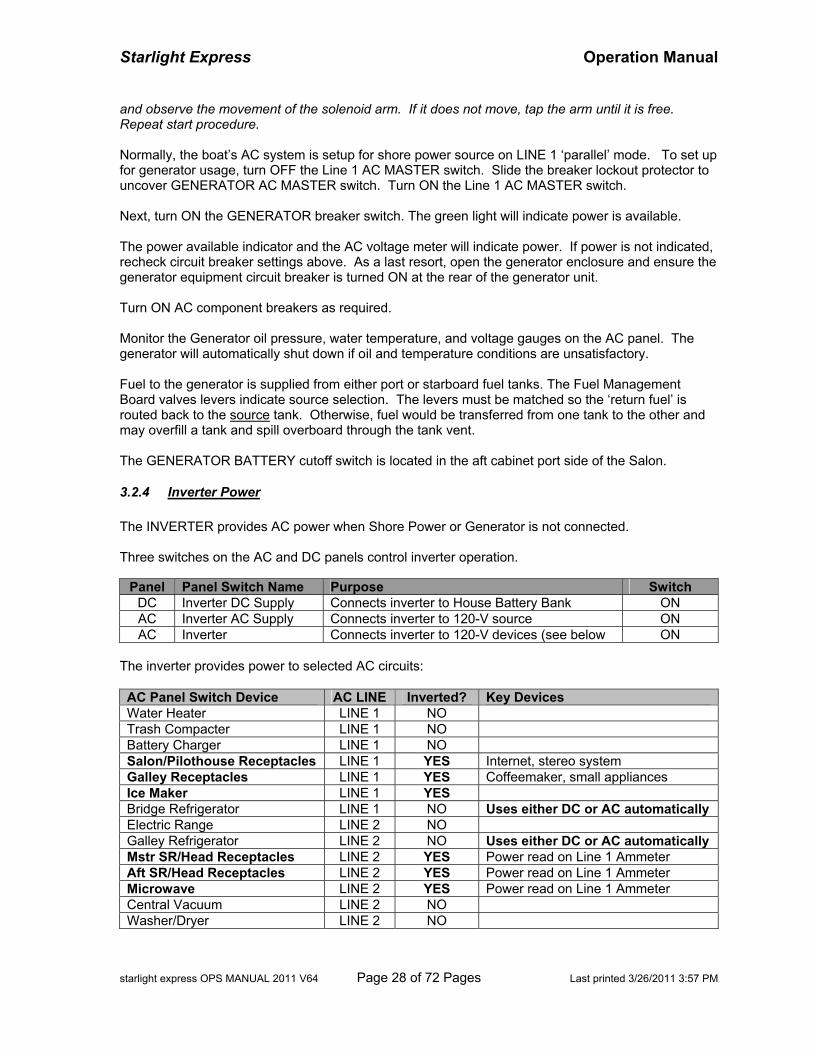
3.2.4 Inverter Power The INVERTER provides AC power when Shore Power or Generator is not connected. Three switches on the AC and DC panels control inverter operation.
Panel Panel Switch Name Purpose Switch DC Inverter DC Supply Connects inverter to House Battery Bank ON AC Inverter AC Supply Connects inverter to 120-V source ON AC Inverter Connects inverter to 120-V devices (see below ON
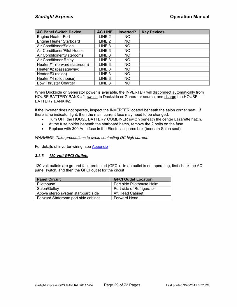
The inverter provides power to selected AC circuits: AC Panel Switch Device AC LINE Inverted? Key Devices Water Heater LINE 1 NO Trash Compacter LINE 1 NO Battery Charger LINE 1 NO Salon/Pilothouse Receptacles LINE 1 YES Internet, stereo system Galley Receptacles LINE 1 YES Coffeemaker, small appliances Ice Maker LINE 1 YES Bridge Refrigerator LINE 1 NO Uses either DC or AC automatically Electric Range LINE 2 NO Galley Refrigerator LINE 2 NO Uses either DC or AC automatically Mstr SR/Head Receptacles LINE 2 YES Power read on Line 1 Ammeter Aft SR/Head Receptacles LINE 2 YES Power read on Line 1 Ammeter Microwave LINE 2 YES Power read on Line 1 Ammeter Central Vacuum LINE 2 NO Washer/Dryer LINE 2 NO
Starlight Express Operation Manual
starlight express OPS MANUAL 2011 V64 Page 29 of 72 Pages Last printed 3/26/2011 3:57 PM
AC Panel Switch Device AC LINE Inverted? Key Devices Engine Heater Port LINE 2 NO Engine Heater Starboard LINE 2 NO Air Conditioner/Salon LINE 3 NO Air Conditioner/Pilot House LINE 3 NO Air Conditioner/Staterooms LINE 3 NO Air Conditioner Relay LINE 3 NO Heater #1 (forward stateroom) LINE 3 NO Heater #2 (passageway) LINE 3 NO Heater #3 (salon) LINE 3 NO Heater #4 (pilothouse) LINE 3 NO Bow Thruster Charger LINE 3 NO
When Dockside or Generator power is available, the INVERTER will disconnect automatically from HOUSE BATTERY BANK #2, switch to Dockside or Generator source, and charge the HOUSE BATTERY BANK #2. If the Inverter does not operate, inspect the INVERTER located beneath the salon corner seat. If there is no indicator light, then the main current fuse may need to be changed.
• Turn OFF the HOUSE BATTERY COMBINER switch beneath the center Lazarette hatch. • At the fuse holder beneath the starboard hatch, remove the 2 bolts on the fuse • Replace with 300 Amp fuse in the Electrical spares box (beneath Salon seat).
WARNING: Take precautions to avoid contacting DC high current.
For details of inverter wiring, see Appendix
3.2.5 120-volt GFCI Outlets 120-volt outlets are ground-fault protected (GFCI). In an outlet is not operating, first check the AC panel switch, and then the GFCI outlet for the circuit Panel Circuit GFCI Outlet Location Pilothouse Port side Pilothouse Helm Salon/Galley Port side of Refrigerator Above stereo system starboard side Aft Head Cabinet Forward Stateroom port side cabinet Forward Head

Starlight Express Operation Manual
starlight express OPS MANUAL 2011 V64 Page 30 of 72 Pages Last printed 3/26/2011 3:57 PM
BLANK PAGE
Starlight Express Operation Manual
starlight express OPS MANUAL 2011 V64 Page 31 of 72 Pages Last printed 3/26/2011 3:57 PM
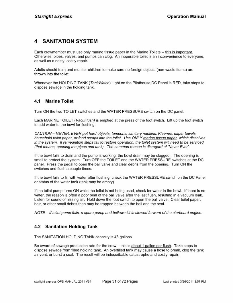
4 SANITATION SYSTEM Each crewmember must use only marine tissue paper in the Marine Toilets -- this is important. Otherwise, pipes, valves, and pumps can clog. An inoperable toilet is an inconvenience to everyone, as well as a nasty, costly repair. Adults should train and monitor children to make sure no foreign objects (non-waste items) are thrown into the toilet. Whenever the HOLDING TANK (TankWatch) Light on the Pilothouse DC Panel is RED, take steps to dispose sewage in the holding tank.
4.1 Marine Toilet Turn ON the two TOILET switches and the WATER PRESSURE switch on the DC panel. Each MARINE TOILET (VacuFlush) is emptied at the press of the foot switch. Lift up the foot switch to add water to the bowl for flushing. CAUTION – NEVER, EVER put hard objects, tampons, sanitary napkins, Kleenex, paper towels, household toilet paper, or food scraps into the toilet. Use ONLY marine tissue paper, which dissolves in the system. If remediation steps fail to restore operation, the toilet system will need to be serviced (that means, opening the pipes and tank). The common reason is disregard of ‘Never Ever’. If the bowl fails to drain and the pump is working, the bowl drain may be clogged. The opening is small to protect the system. Turn OFF the TOILET and the WATER PRESSURE switches at the DC panel. Press the pedal to open the ball valve and clear debris from the opening. Turn ON the switches and flush a couple times. If the bowl fails to fill with water after flushing, check the WATER PRESSURE switch on the DC Panel or status of the water tank (tank may be empty). If the toilet pump turns ON while the toilet is not being used, check for water in the bowl. If there is no water, the reason is often a poor seal of the ball valve after the last flush, resulting in a vacuum leak. Listen for sound of hissing air. Hold down the foot switch to open the ball valve. Clear toilet paper, hair, or other small debris than may be trapped between the ball and the seal. NOTE – If toilet pump fails, a spare pump and bellows kit is stowed forward of the starboard engine.
4.2 Sanitation Holding Tank The SANITATION HOLDING TANK capacity is 48 gallons. Be aware of sewage production rate for the crew – this is about 1 gallon per flush. Take steps to dispose sewage from filled holding tank. An overfilled tank may cause a hose to break, clog the tank air vent, or burst a seal. The result will be indescribable catastrophe and costly repair.
Starlight Express Operation Manual
starlight express OPS MANUAL 2011 V64 Page 32 of 72 Pages Last printed 3/26/2011 3:57 PM
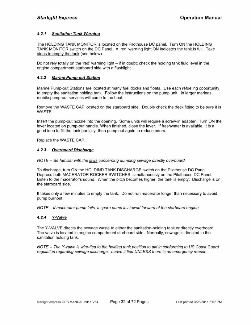
4.2.1 Sanitation Tank Warning The HOLDING TANK MONITOR is located on the Pilothouse DC panel. Turn ON the HOLDING TANK MONITOR switch on the DC Panel. A ‘red’ warning light ON indicates the tank is full. Take steps to empty the tank (see below). Do not rely totally on the ‘red’ warning light – if in doubt; check the holding tank fluid level in the engine compartment starboard side with a flashlight
4.2.2 Marine Pump out Station Marine Pump-out Stations are located at many fuel docks and floats. Use each refueling opportunity to empty the sanitation holding tank. Follow the instructions on the pump unit. In larger marinas, mobile pump-out services will come to the boat. Remove the WASTE CAP located on the starboard side. Double check the deck fitting to be sure it is WASTE. Insert the pump-out nozzle into the opening. Some units will require a screw-in adapter. Turn ON the lever located on pump-out handle. When finished, close the lever. If freshwater is available, it is a good idea to fill the tank partially, then pump out again to reduce odors. Replace the WASTE CAP.
4.2.3 Overboard Discharge NOTE -- Be familiar with the laws concerning dumping sewage directly overboard. To discharge, turn ON the HOLDIND TANK DISCHARGE switch on the Pilothouse DC Panel. Depress both MACERATOR ROCKER SWITCHES simultaneously on the Pilothouse DC Panel. Listen to the macerator’s sound. When the pitch becomes higher, the tank is empty. Discharge is on the starboard side. It takes only a few minutes to empty the tank. Do not run macerator longer than necessary to avoid pump burnout. NOTE – If macerator pump fails, a spare pump is stowed forward of the starboard engine.
4.2.4 Y-Valve The Y-VALVE directs the sewage waste to either the sanitation-holding tank or directly overboard. The valve is located in engine compartment starboard side. Normally, sewage is directed to the sanitation holding tank. NOTE -- The Y-valve is wire-tied to the holding tank position to aid in conforming to US Coast Guard regulation regarding sewage discharge. Leave it tied UNLESS there is an emergency reason.
Starlight Express Operation Manual
starlight express OPS MANUAL 2011 V64 Page 33 of 72 Pages Last printed 3/26/2011 3:57 PM
5 WATER SYSTEMS
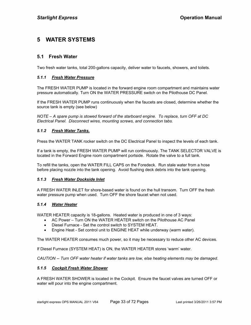
5.1 Fresh Water Two fresh water tanks, total 200-gallons capacity, deliver water to faucets, showers, and toilets.
5.1.1 Fresh Water Pressure The FRESH WATER PUMP is located in the forward engine room compartment and maintains water pressure automatically. Turn ON the WATER PRESSURE switch on the Pilothouse DC Panel. If the FRESH WATER PUMP runs continuously when the faucets are closed, determine whether the source tank is empty (see below) NOTE – A spare pump is stowed forward of the starboard engine. To replace, turn OFF at DC Electrical Panel. Disconnect wires, mounting screws, and connection tabs.
5.1.2 Fresh Water Tanks. Press the WATER TANK rocker switch on the DC Electrical Panel to inspect the levels of each tank. If a tank is empty, the FRESH WATER PUMP will run continuously. The TANK SELECTOR VALVE is located in the Forward Engine room compartment portside. Rotate the valve to a full tank. To refill the tanks, open the WATER FILL CAPS on the Foredeck. Run stale water from a hose before placing nozzle into the tank opening. Avoid flushing deck debris into the tank opening.
5.1.3 Fresh Water Dockside Inlet A FRESH WATER INLET for shore-based water is found on the hull transom. Turn OFF the fresh water pressure pump when used. Turn OFF the shore faucet when not used.
5.1.4 Water Heater WATER HEATER capacity is 18-gallons. Heated water is produced in one of 3 ways:
• AC Power – Turn ON the WATER HEATER switch on the Pilothouse AC Panel • Diesel Furnace - Set the control switch to SYSTEM HEAT. • Engine Heat - Set control unit to ENGINE HEAT while underway (warm water).
The WATER HEATER consumes much power, so it may be necessary to reduce other AC devices. If Diesel Furnace (SYSTEM HEAT) is ON, the WATER HEATER stores ‘warm’ water. CAUTION -- Turn OFF water heater if water tanks are low, else heating elements may be damaged.
5.1.5 Cockpit Fresh Water Shower A FRESH WATER SHOWER is located in the Cockpit. Ensure the faucet valves are turned OFF or water will pour into the engine compartment.
Starlight Express Operation Manual
starlight express OPS MANUAL 2011 V64 Page 34 of 72 Pages Last printed 3/26/2011 3:57 PM
The outdoor shower provides hot and cold water. Use to wash mud from people, shoes, and clothing.
5.1.6 Fresh Water Washdown Hose A FRESH WATER WASHDOWN hose is located in the Cockpit starboard cabinet. Ensure the hose nozzle and faucet are OFF when not in use to avoid wasting fresh water.
5.2 Gray Water
5.2.1 Sinks Wastewater (also known as ‘gray’ water) from the galley and salon sinks is gravity-drained overboard.
5.2.2 Showers Wastewater from the showers and head sinks is pumped overboard. A Sump Pump Box located in the Passageway starboard beneath the forward shower collects wastewater from the Head sinks and the Forward Head shower. The pump will cycle on/off automatically. WARNING -- If pump fails, wastewater will overflow into the passageway (wet the carpet). Check the TUB-SINK breaker button on the Pilothouse DC Panel. If breaker is okay and pump remains off, the pump may need replacement (see Spare Parts list). Open lid of sump box. NOTE -- If pump operates continuously, debris may have interfered with the sensor switch. Open the lid, lift out the cylinder-shaped strainer. Wipe scum from switch and the inside. Replace the strainer. The Aft Head Shower waste water is pumped overboard. Turn ON the SHOWER SUMP switch on the Pilothouse DC Panel. Turn ON the SHOWER switch in the Aft Head cabinet to drain the shower.
5.3 Raw Water ‘Raw water’ depends on the body of water (fresh, saltwater) the boat is floating. RAW WATER WASHDOWNS are available at 2 locations. Location Spigot Location Bow Inside Foredeck Locker Cockpit Inside Cockpit Portside Cabinet
Turn ON the WASHDOWN switch at the Pilothouse DC Panel. When not in use, turn OFF the switch to remove load on the pressure pump.
5.4 Bilge Water Three automatic and three manual bilge pumps, in pairs, are in engine room (AFT), forward engine room (MID), and passageway (FORWARD). Turn ON manual BILGE pumps at DC Electrical panel, and operate from pilothouse or bridge. Automatic pumps connect directly to battery and sensors. NOTE -- If an ‘automatic’ pump cycles on/off (red light on panels), turn ON the paired ‘manual’ pump to help remove excess bilge water. Sloshing bilge water may trip the automatic sensors, causing unnecessary cycles. This occurs commonly with the FORWARD pair next to the Aft Stateroom; raise the lowest step in the passageway at the galley end to inspect the sump.
Starlight Express Operation Manual
starlight express OPS MANUAL 2011 V64 Page 35 of 72 Pages Last printed 3/26/2011 3:57 PM
6 GALLEY-SALON
6.1 Galley Ware Utensils and dishware are stowed in the Galley portside cabinets and drawers. Drink glasses are stowed in the ceiling cabinet above the galley sink. Wine glasses are stowed beneath the starboard salon sink. Pots and skillets are stowed in the sliding drawer beneath the refrigerator. Pans and oven accessories are stowed in the cabinet beneath the oven. Small kitchen appliances and cleanup items are stowed beneath the galley sink. For a detailed inventory of all galley equipment, see Appendix E, Galley Inventory. NOTE -- When underway in rough seas, push-in all cabinet/drawer LATCHES to prevent contents from spilling out.
6.2 Sink Countertop Protect the countertops from damage. Use cutting boards stowed in the cabinet beneath the oven. Keep the sink countertop dry. Water will puddle against the teak panel behind the sink faucet and run around the right of the panel onto the salon carpet. This commonly occurs when water is splashed during use of faucet.
6.3 Microwave The microwave is a GE Spacemaker unit. Turn ON the MICROWAVE switch at the Pilothouse AC Panel. The Microwave can be used with shore, generator, or inverter power. The unit uses a large amount of power (up to 15 amps). It may be necessary to reduce use of other AC devices to avoid tripping the DC Circuit Breaker. Read power consumption on Ammeter 2. The Microwave is connected to the Inverter system, so it will operate when AC power is not available. NOTE -- During meal preparation, it may be necessary to turn OFF non-essential AC devices when shore power is less than 30-amps, in order to use several galley appliances simultaneously.
6.4 Range and Oven
Starlight Express Operation Manual
starlight express OPS MANUAL 2011 V64 Page 36 of 72 Pages Last printed 3/26/2011 3:57 PM
The boat is equipped with a 3-burner Princess Range and Oven. Turn ON the ELECTRIC RANGE switch at the Pilothouse AC panel. The unit uses a large amount of AC power (up to 25 amps). It may be necessary to reduce use of other AC devices to avoid tripping the DC Circuit Breaker. Read power consumption on Ammeter 2. Lift the cook top surface cover to a vertical position and fold the top portion to form a shelf. NOTE -- Ensure the cover is locked down firmly into the vertical position to disengage the range ‘safety’ device; otherwise, the range controls will not operate. Top burners have different cooking temperatures. The LEFT and RIGHT burners are ‘High” 1100-watt burners. The REAR burner is a ‘Medium’ 550-water burner. NOTE – If the burner elements are removed for cleaning, they may become re-installed incorrectly. The burner elements must match the controls - the high 1100-watt elements are placed in the left front and right front positions and the medium 550-watt element in the rear position. Check the wattage values stamped on the frame of burner element. The range TOGGLE switch enables selection of BURNER and OVEN operation. Flipping the switch to ‘Top Burners’, allows ALL three top burners to be used. Flipping the switch to ‘Oven’ enables the OVEN, the REAR burner, and the RIGHT burner to be used – the LEFT burner is disabled. Counter lights beneath the Microwave illuminate the cook top surface. Turn ON the MICROWAVE switch at the Pilothouse AC panel. Press ‘Light’ on the Microwave Oven panel. The Microwave fan will vent odors and steam overboard. Turn ON the MICROWAVE switch at the Pilothouse AC panel. Press ‘Fan’ on the Microwave panel to ‘High’ or ‘Low’.
6.5 Refrigeration
6.5.1 Refrigerator-Freezer The Galley REFRIGERATOR-FREEZER is a Norcold 6.3-cu-ft model. It operates on DC power and switches to operate on AC power automatically whenever available (dual-mode).
• Turn ON the REFRIGERATOR switch on the Pilothouse DC Panel • Turn ON the REFRIGERATOR switch on the Pilothouse AC Panel • Turn ON the power switch below the refrigerator door and adjust the temperature
6.5.2 Bridge Refrigerator The Bridge REFRIGERATOR is a Norcold 2.7-cu-ft model. It operates on DC power and switches to AC power automatically whenever available (dual mode).
• Turn ON the ENTERTAINMENT CENTER switch on the Pilothouse DC Panel • Turn ON the BRIDGE REFRIGERATOR switch on the Pilothouse AC Panel • Turn ON the local power switch and adjust the temperature
CAUTION -- The refrigerator consumes MUCH power when operating on DC power. Consider selective use, or turn OFF and use the Ice Coolers. It also creates overhead noise in the Salon.
Starlight Express Operation Manual
starlight express OPS MANUAL 2011 V64 Page 37 of 72 Pages Last printed 3/26/2011 3:57 PM
6.6 Food Storage Dry food and canned food may be stored in the Galley cabinets or in the Salon cabinets portside. Wine bottles may be stored in beneath the Salon sink starboard. The Cockpit Cooler may be used for drink storage or large food items (see Cooler).
6.7 Coffee Maker The coffee pot is a GE 12-cup Digital Coffee Maker. To set the time:
• Press the ‘hr’ button • Press the ‘min’ button
To brew manually:
• Insert filter into basket • Add water • Add coffee into basket (about ¾ cup drip-ground coffee makes 12-cups coffee) • Press ‘On’ button once to start brewing
To brew automatically:
• Set the clock time (see above) • Add water and coffee (see above) • Press ‘Prog’ button once. Use ‘hr’ and ‘min’ buttons to set time when brewing is to complete • Press ‘Prog’ button once again to fix setting • Press ‘Auto’ button to initiate automatic brewing • Audible tone will sound when brewing is complete
6.8 Blender The blender is a Chefmate, 5-speed unit. Plug into any 120-V outlet. Components are stowed in the cabinet beneath the sink.
6.9 Trash Compactor Spare compactor bags are stowed normally in the galley cabinet. The ‘tall’ size (13-gallen) plastic kitchen bag, available at supermarkets, will stretch over the rim. Turn ON the TRASH COMPACTOR on the Pilothouse AC Panel. Follow the directions on the compactor panel.
Starlight Express Operation Manual
starlight express OPS MANUAL 2011 V64 Page 38 of 72 Pages Last printed 3/26/2011 3:57 PM
6.10 Ice Maker The ICE MAKER is located in the Salon starboard. Turn ON the ICEMAKER switch on the Pilothouse AC Panel. The local power switch is located behind the vent cover via a finger hole at the top, and it is normally ON. Push the ice sensor bar to downward position to start. The Ice Maker is connected to the Inverter system, so it will operate when AC power is not available. Ensure the plastic bin is in the icemaker at all times. Should the DC be turned OFF, the ice melt water will soak the carpet. NOTE -- For continuous ice production, ensure the ice sensor bar remains in the downward position after each tray cycle.
6.11 Salon Dining Table To expand the dining table, slide the 4 lateral support bars outward and flip the table panels onto the supports. Rotate the table to fit the seating around the bench sofa. To change the elevation of the table, have two persons lift the tabletop upward – it is spring-assisted; do not separate table from pedestal. Stack blocks (located beneath the table) between the pedestal top and table bottom to the desired height. Lower the tabletop. To return to coffee table configuration, reverse the procedure. Use the 2 salon sofa chairs for additional seating.
6.12 Additional Bed Space Two persons may sleep on the salon sofas, one on starboard side, and one the aft side. To expand legroom on the aft side sofa, place the cushioned air chair at the end. The pilothouse bench may be used as a small bunk. Place the ‘seat bridge’ across the opening to the port pilothouse door. Supplementary padding on the floor of the salon and pilothouse offer additional bed space possibilities (young folks sometimes prefer this option).
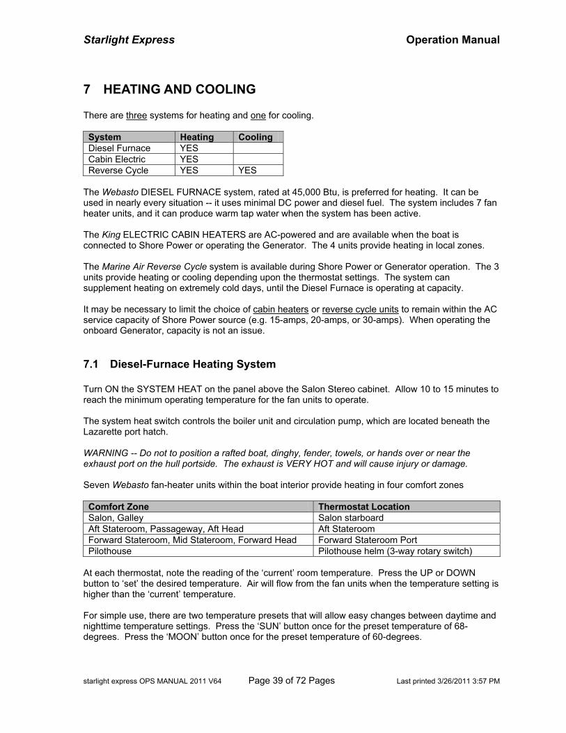
Starlight Express Operation Manual
starlight express OPS MANUAL 2011 V64 Page 39 of 72 Pages Last printed 3/26/2011 3:57 PM
7 HEATING AND COOLING There are three systems for heating and one for cooling. System Heating Cooling Diesel Furnace YES Cabin Electric YES Reverse Cycle YES YES
The Webasto DIESEL FURNACE system, rated at 45,000 Btu, is preferred for heating. It can be used in nearly every situation -- it uses minimal DC power and diesel fuel. The system includes 7 fan heater units, and it can produce warm tap water when the system has been active. The King ELECTRIC CABIN HEATERS are AC-powered and are available when the boat is connected to Shore Power or operating the Generator. The 4 units provide heating in local zones. The Marine Air Reverse Cycle system is available during Shore Power or Generator operation. The 3 units provide heating or cooling depending upon the thermostat settings. The system can supplement heating on extremely cold days, until the Diesel Furnace is operating at capacity. It may be necessary to limit the choice of cabin heaters or reverse cycle units to remain within the AC service capacity of Shore Power source (e.g. 15-amps, 20-amps, or 30-amps). When operating the onboard Generator, capacity is not an issue.
7.1 Diesel-Furnace Heating System Turn ON the SYSTEM HEAT on the panel above the Salon Stereo cabinet. Allow 10 to 15 minutes to reach the minimum operating temperature for the fan units to operate. The system heat switch controls the boiler unit and circulation pump, which are located beneath the Lazarette port hatch. WARNING -- Do not to position a rafted boat, dinghy, fender, towels, or hands over or near the exhaust port on the hull portside. The exhaust is VERY HOT and will cause injury or damage. Seven Webasto fan-heater units within the boat interior provide heating in four comfort zones Comfort Zone Thermostat Location Salon, Galley Salon starboard Aft Stateroom, Passageway, Aft Head Aft Stateroom Forward Stateroom, Mid Stateroom, Forward Head Forward Stateroom Port Pilothouse Pilothouse helm (3-way rotary switch)
At each thermostat, note the reading of the ‘current’ room temperature. Press the UP or DOWN button to ‘set’ the desired temperature. Air will flow from the fan units when the temperature setting is higher than the ‘current’ temperature. For simple use, there are two temperature presets that will allow easy changes between daytime and nighttime temperature settings. Press the ‘SUN’ button once for the preset temperature of 68-degrees. Press the ‘MOON’ button once for the preset temperature of 60-degrees.
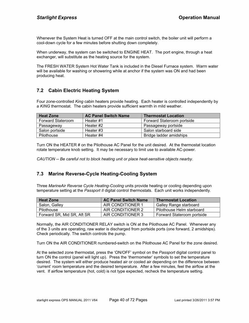
Starlight Express Operation Manual
starlight express OPS MANUAL 2011 V64 Page 40 of 72 Pages Last printed 3/26/2011 3:57 PM
Whenever the System Heat is turned OFF at the main control switch, the boiler unit will perform a cool-down cycle for a few minutes before shutting down completely. When underway, the system can be switched to ENGINE HEAT. The port engine, through a heat exchanger, will substitute as the heating source for the system. The FRESH WATER System Hot Water Tank is included in the Diesel Furnace system. Warm water will be available for washing or showering while at anchor if the system was ON and had been producing heat.
7.2 Cabin Electric Heating System Four zone-controlled King cabin heaters provide heating. Each heater is controlled independently by a KING thermostat. The cabin heaters provide sufficient warmth in mild weather. Heat Zone AC Panel Switch Name Thermostat Location Forward Stateroom Heater #1 Forward Stateroom portside Passageway Heater #2 Passageway portside Salon portside Heater #3 Salon starboard side Pilothouse Heater #4 Bridge ladder amidships
Turn ON the HEATER # on the Pilothouse AC Panel for the unit desired. At the thermostat location rotate temperature knob setting. It may be necessary to limit use to available AC-power. CAUTION -- Be careful not to block heating unit or place heat-sensitive objects nearby.
7.3 Marine Reverse-Cycle Heating-Cooling System Three MarineAir Reverse Cycle Heating-Cooling units provide heating or cooling depending upon temperature setting at the Passport II digital control thermostats. Each unit works independently. Heat Zone AC Panel Switch Name Thermostat Location Salon, Galley AIR CONDITIONER 1 Galley Range starboard Pilothouse AIR CONDITIONER 2 Pilothouse Helm starboard Forward SR, Mid SR, Aft SR AIR CONDITIONER 3 Forward Stateroom portside
Normally, the AIR CONDITIONER RELAY switch is ON at the Pilothouse AC Panel. Whenever any of the 3 units are operating, raw water is discharged from portside ports (one forward, 2 amidships). Check periodically. The switch controls the pump. Turn ON the AIR CONDITIONER numbered-switch on the Pilothouse AC Panel for the zone desired. At the selected zone thermostat, press the ‘ON/OFF’ symbol on the Passport digital control panel to turn ON the control (panel will light up). Press the ‘thermometer’ symbols to set the temperature desired. The system will either produce heated air or cooled air depending on the difference between ‘current’ room temperature and the desired temperature. After a few minutes, feel the airflow at the vent. If airflow temperature (hot, cold) is not type expected, recheck the temperature setting.
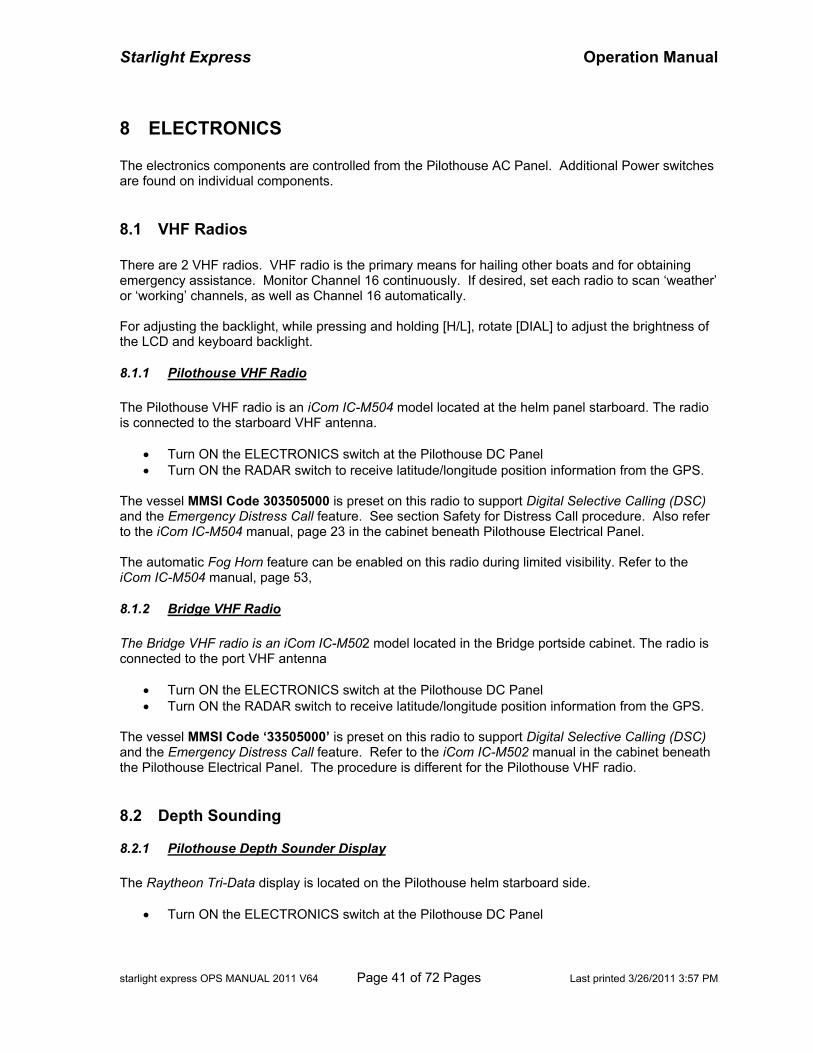
Starlight Express Operation Manual
starlight express OPS MANUAL 2011 V64 Page 41 of 72 Pages Last printed 3/26/2011 3:57 PM
8 ELECTRONICS The electronics components are controlled from the Pilothouse AC Panel. Additional Power switches are found on individual components.
8.1 VHF Radios There are 2 VHF radios. VHF radio is the primary means for hailing other boats and for obtaining emergency assistance. Monitor Channel 16 continuously. If desired, set each radio to scan ‘weather’ or ‘working’ channels, as well as Channel 16 automatically. For adjusting the backlight, while pressing and holding [H/L], rotate [DIAL] to adjust the brightness of the LCD and keyboard backlight.
8.1.1 Pilothouse VHF Radio The Pilothouse VHF radio is an iCom IC-M504 model located at the helm panel starboard. The radio is connected to the starboard VHF antenna.
• Turn ON the ELECTRONICS switch at the Pilothouse DC Panel • Turn ON the RADAR switch to receive latitude/longitude position information from the GPS.
The vessel MMSI Code 303505000 is preset on this radio to support Digital Selective Calling (DSC) and the Emergency Distress Call feature. See section Safety for Distress Call procedure. Also refer to the iCom IC-M504 manual, page 23 in the cabinet beneath Pilothouse Electrical Panel. The automatic Fog Horn feature can be enabled on this radio during limited visibility. Refer to the iCom IC-M504 manual, page 53,
8.1.2 Bridge VHF Radio The Bridge VHF radio is an iCom IC-M502 model located in the Bridge portside cabinet. The radio is connected to the port VHF antenna
• Turn ON the ELECTRONICS switch at the Pilothouse DC Panel • Turn ON the RADAR switch to receive latitude/longitude position information from the GPS.
The vessel MMSI Code ‘33505000’ is preset on this radio to support Digital Selective Calling (DSC) and the Emergency Distress Call feature. Refer to the iCom IC-M502 manual in the cabinet beneath the Pilothouse Electrical Panel. The procedure is different for the Pilothouse VHF radio.
8.2 Depth Sounding
8.2.1 Pilothouse Depth Sounder Display The Raytheon Tri-Data display is located on the Pilothouse helm starboard side.
• Turn ON the ELECTRONICS switch at the Pilothouse DC Panel
Starlight Express Operation Manual
starlight express OPS MANUAL 2011 V64 Page 42 of 72 Pages Last printed 3/26/2011 3:57 PM
• Turn ON the RADAR switch at the Pilothouse DC Panel. The display repeats depth information from the DSM-300 sounder. Reading is in “feet”. Refer to the Raytheon manual in the cabinet beneath the Pilothouse Electrical Panel. The E-series displays also show depth sounding information – See details in the Raymarine E-Series Network Display manual beneath the Pilothouse Electrical Panel.
8.2.2 Bridge Depth Sounder The Uniden depth sounder is on the Bridge helm.
• Turn ON the ELECTRONICS switch at the Pilothouse DC Panel • Turn ON the DEPTH SOUNDER rocker switch on the Bridge helm panel.
Set the scale, shallow alarm, and deep alarm as desired. Refer to the Uniden manual in the cabinet beneath the Pilothouse Electrical Panel. CAUTION -- The sounder provides reliable reading in shallow waters only. Use this sounder as an auxiliary. When in doubt, cross check soundings on either E-series multifunction display.
8.3 Multifunction Displays Two Raymarine E-Series MULTIFUNCTION DISPLAYS integrate the control and information display of the boat sensors and the navigation systems. The displays are sunlight viewable.
• E-120 Display – Pilothouse. Turn ON the RADAR switch on Pilothouse DC Panel first. • E-80 Display – Bridge. Turn ON the ELECTRONICS switch on the Pilothouse DC Panel.
To startup the systems:
• First, turn ON the E-120. This is the Master unit and the database for the networked system. • Next, turn ON the E-80. This may be skipped to do later.
NOTE – If the E-80 warning messages persist after an out-of-sequence startup, the easiest way to correct the situation is to turn OFF both multi-function units, then restart the systems. Each display integrates the following equipment and functions:
• Radar – scanner overlay • GPS – latitude, longitude, speed over ground, course over ground • Electronic Chart – Navionics Platinum geographic overlay, waypoint, route • Digital Sounder – sounding, fish finding, speed thru water, water temperature • Gyro Compass – heading, course deviation • Auto Pilot – course tracking • VHF Radio DSC – support for position location • MOB Emergency – man overboard position location • Alarms – depth limit warning, anchor movement, time lapse
Data is shared across the E-series network across both displays. Refer to details in sections below.
Starlight Express Operation Manual
starlight express OPS MANUAL 2011 V64 Page 43 of 72 Pages Last printed 3/26/2011 3:57 PM
CAUTION -- To avoid damage to the window coating, rinse with fresh water. DO NOT use dry cloth, or cleaning solution, polish, or spray. Wipe smears very gently with a clean micro fiber cleaning cloth.
8.3.1 Radar Scanner The RADAR scanner is a Raymarine RD-424 4KW model and is rated 48-nautical miles. However, useful range is limited to line-of-sight, affected by fog, rain, target height, landform, or setting sensitivity. Turn ON the RADAR switch on the Pilothouse DC Panel (which also turns on the E-120). To control the radar scanner, turn ON the E-120 display, switch scanner ON, and select operating mode TX (transmit). Each E-series display provides local control of the radar presentation. Refer to the Raymarine E-120 manual or the quick reference guide in the in the cabinet beneath the Pilothouse Electrical Panel.
8.3.2 Global Positioning System (GPS) The GPS antenna is a Raymarine Raystar 125 model and provides latitude and longitude position data. Turn ON the RADAR switch on the Pilothouse DC Panel. The GPS antenna is connected to the E-Series network and shares data with both multifunctional displays, the Autopilot, and the VHF radios.
8.3.3 Electronic Chart The ELECTRONIC CHART includes the Navionics Platinum 913P (Vancouver Island) package. The electronic flash card, inserted into the E-120 multi-function display, provides chart information. Turn ON RADAR switch on the Pilothouse DC Panel, which turns ON the E-120 display. Each E-series display allows local control for presentation of the chart data. For additional information, see Charts in the Navigation Section.
8.3.4 Digital Sounder The DIGITAL SOUNDER is a Raymarine DSC-300 unit and provides sounding, bottom characteristics, fish locating, speed-through-water, and water temperature. Turn ON the ELECTRONICS switch on the Pilothouse DC Panel. The B744 transducer, located just forward of the starboard engine, is connected to the DSC-300 unit. Each E-series display allows local control of the digital sounder settings. Refer to the Quick Reference Guide or Raymarine manual found in the cabinet beneath the Electrical Panel.
8.4 Speed Logs SPEED THROUGH WATER (STW) may be read on the Raytheon Tri-Data display on the Pilothouse panel. It measures speed in knots. The B744 transducer paddlewheel provides source data to DSM-300 sounder, then to the Tri-Data display. STW may be also read on the data bar on each Raymarine E-Series display.
Starlight Express Operation Manual
starlight express OPS MANUAL 2011 V64 Page 44 of 72 Pages Last printed 3/26/2011 3:57 PM
SPEED OVER GROUND (SOG) may be read on the data bar of each Raymarine E-series display. The GPS provides the geographic location changes and the E-120 unit performs the calculation.
8.5 Autopilot The AUTOPILOT control display is located on the Pilothouse instrument panel portside. In addition, an AUTOPILOT WIRELESS REMOTE control handset is found in the bridge radio cabinet. The AUTOPILOT will aid in maintaining chosen heading. Turn ON the AUTOPILOT switch at the Pilothouse DC Panel, and turn ON the RADAR switch to link the Raymarine E-120 multi-function display and GPS for course information. WARNING -- Be familiar of safe methods for using the autopilot. ALWAYS know the status of the autopilot – is it on auto? Or is it on standby? Turning the helm to avoid debris or traffic while in ‘auto’ WILL NOT place the autopilot in ‘standby’ -- the boat WILL maintain the ‘auto’ course despite your action. Refer to the Raymarine Autopilot manual in cabinet beneath Pilothouse Electrical Panel. A RUDDER POSITION INDICATOR is displayed at the bottom scale of the display. For night illumination, press the ‘Lamp’ button to change the light level of the Autopilot and the Tri-Data display.
8.6 Cell Phone Service Cell phone service is available from almost anywhere in Puget Sound, the Strait of Juan de Fuca, and the Strait of Georgia. Local ‘hot spots’ are available at several remote British Columbia coastal locations (e.g. Big Bay, Minstrel Island, Echo Bay). Roaming and long distance charges apply.
8.7 Internet Service Internet service is accessible when moored and in line-of-site of an Internet ‘access point’ in a marina or nearby community. The boat’s network will not maintain Internet connection while on the move. Turn ON the SALON/PILOTHOUSE RECEPTACLES switch. The system is connected to the INVERTER and operates from any power source. A diagram of the boat network is at Appendix K.. The 3-ft antenna is located on the mast portside of the radar dome. NOTE -- Satellite TV has no relationship with Internet service. Connect to the Internet in four steps:
• Step 1 - Start the Wi-Fi enabled laptop/PDA (for example, Dell WLAN card) • Step 2 - Connect the PC or Wi-Fi to the boat LAN (local area network), named ‘stx’ • Step 3 - Connect Boat LAN to an ISP (Internet Service Provider) (e.g. Broadband Express) • Step 4 – Launch Internet Browser public web site (such as http://www.google.com)
NOTE – If ‘wireless’ use is not desired, skip Steps 1 and 2. Connect the PC to the LAN receptacle at the Pilothouse starboard navigation station with a Cat5 network cable. Go to Step 3. Step 1. Activate the PC/PDA Wireless Connector.
Starlight Express Operation Manual
starlight express OPS MANUAL 2011 V64 Page 45 of 72 Pages Last printed 3/26/2011 3:57 PM
This is dependent upon the PC or PDA hardware. Normally, turn on the ‘Wi-Fi’ or the PC’s wireless card radio, and check the connection status. Step 2. Connect PC/PDA to ‘Starlight Express’ LAN (local area network). Using the PC’s network application, search for the SSID ‘stx’ – it should indicate a strong signal. Press the application’s select/connect button. If connection is successful, go to Step 3. If this is first attempt to select ‘stx’, the PC application should prompt for the network security code or pass-phrase. Enter the code ‘DE9QDQBCRT’ – it is case sensitive. Press the application’s select/connect button. Verify successful connection to ‘stx’. Save the SSID ‘stx’ site to the PC’s network list. Next time, the PC application should not prompt for security code. Step 3. Connect ‘Starlight Express’ LAN to an ISP (Internet Service Provider). At each moorage location, find an available ISP access point in the marina or nearby community. If same location since the previous network session, either:
• Go to Step 4, if satisfied with access point service. • Continue below to locate an access point.
Using the PC’s internet browser (e.g. Internet Explorer, Firefox, etc), enter the URL: 192.168.2.254 to enter the Air 802 WLAN AP Setup Browser of the boat’s Wireless Bridge device. In the left menu pane, select ‘Wireless -> Site Survey’. Click ‘Refresh’ and browse the list of access points. Click/select button for an ISP access point (for example ‘bbx’). Then, press ‘Select’ at bottom of page. Wait for the page to verify ‘Connect Successful’. NOTE -- DO NOT re-select ‘stx’ from site survey list – this is the ‘Starlight Express’ LAN. If unsuccessful, retry the access point or try another. Success will depend upon the distance to the ISP antenna and whether the path is free of boats, masts, buildings, or foliage. NOTE -- If desired, try an ISP with ‘no’ Encrypt, highest RSSI and highest Quality. However, the most reliable ISP at most Pacific Northwest marinas is ‘bbx’ (BroadbandXpress), which requires a subscription account (.e.g. $10.95 per day). Details about the service and rates will be displayed while establishing the first Internet session. Also, see details at the website http://www.bbxpress.net. You may find free access points in a local community (e.g. Starbucks). NOTE – Depending upon your Internet browser, it may be necessary to disable the PC’s ‘pop-up blocker’ feature, reset your security settings to ‘medium’, and disable proxies, firewalls, or VPN programs after the browser is launched. NOTE - DO NOT tamper/change settings in the other menu pages of the Setup Browser. Step 4. Establish an Internet Session Enter a web site URL, such as http://www.google.com, to test the Internet connectivity. NOTE – If you selected Broadband Express as the ISP above, the screen will request login to your BBX account and the subscription type. First time users may set up a new account. After successful credit card payment, you will be able to connect to any public web site.

Starlight Express Operation Manual
starlight express OPS MANUAL 2011 V64 Page 46 of 72 Pages Last printed 3/26/2011 3:57 PM
BLANK PAGE
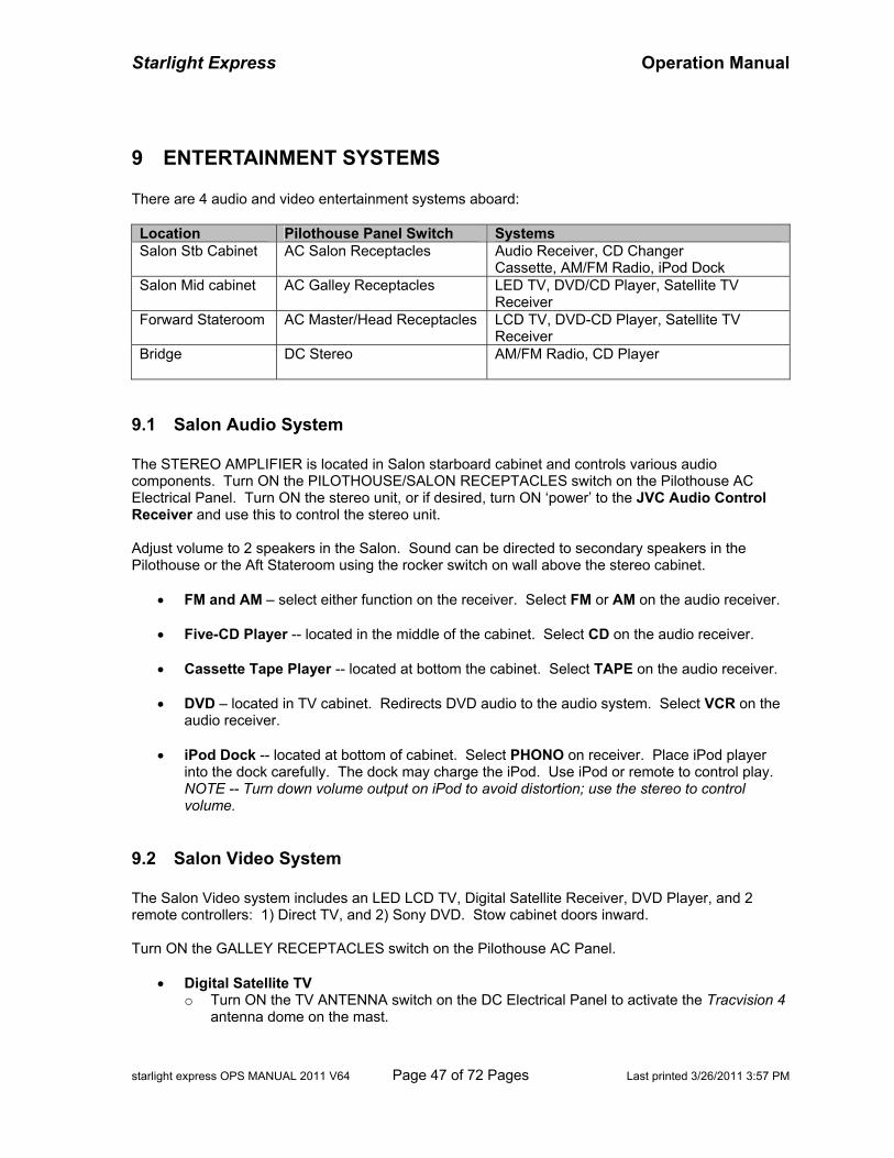
Starlight Express Operation Manual
starlight express OPS MANUAL 2011 V64 Page 47 of 72 Pages Last printed 3/26/2011 3:57 PM
9 ENTERTAINMENT SYSTEMS There are 4 audio and video entertainment systems aboard: Location Pilothouse Panel Switch Systems Salon Stb Cabinet AC Salon Receptacles Audio Receiver, CD Changer
Cassette, AM/FM Radio, iPod Dock Salon Mid cabinet AC Galley Receptacles LED TV, DVD/CD Player, Satellite TV
Receiver Forward Stateroom AC Master/Head Receptacles LCD TV, DVD-CD Player, Satellite TV
Receiver Bridge
DC Stereo AM/FM Radio, CD Player
9.1 Salon Audio System The STEREO AMPLIFIER is located in Salon starboard cabinet and controls various audio components. Turn ON the PILOTHOUSE/SALON RECEPTACLES switch on the Pilothouse AC Electrical Panel. Turn ON the stereo unit, or if desired, turn ON ‘power’ to the JVC Audio Control Receiver and use this to control the stereo unit. Adjust volume to 2 speakers in the Salon. Sound can be directed to secondary speakers in the Pilothouse or the Aft Stateroom using the rocker switch on wall above the stereo cabinet.
• FM and AM – select either function on the receiver. Select FM or AM on the audio receiver.
• Five-CD Player -- located in the middle of the cabinet. Select CD on the audio receiver.
• Cassette Tape Player -- located at bottom the cabinet. Select TAPE on the audio receiver.
• DVD – located in TV cabinet. Redirects DVD audio to the audio system. Select VCR on the audio receiver.
• iPod Dock -- located at bottom of cabinet. Select PHONO on receiver. Place iPod player
into the dock carefully. The dock may charge the iPod. Use iPod or remote to control play. NOTE -- Turn down volume output on iPod to avoid distortion; use the stereo to control volume.
9.2 Salon Video System The Salon Video system includes an LED LCD TV, Digital Satellite Receiver, DVD Player, and 2 remote controllers: 1) Direct TV, and 2) Sony DVD. Stow cabinet doors inward. Turn ON the GALLEY RECEPTACLES switch on the Pilothouse AC Panel.
• Digital Satellite TV o Turn ON the TV ANTENNA switch on the DC Electrical Panel to activate the Tracvision 4
antenna dome on the mast.
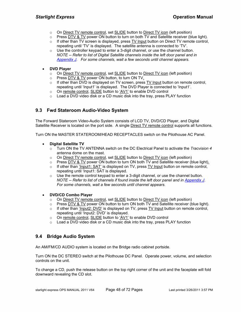
Starlight Express Operation Manual
starlight express OPS MANUAL 2011 V64 Page 48 of 72 Pages Last printed 3/26/2011 3:57 PM
o On Direct TV remote control, set SLIDE button to Direct TV icon (left position) o Press DTV & TV power ON button to turn on both TV and Satellite receiver (blue light). o If other than TV screen is displayed, press TV Input button on Direct TV remote control,
repeating until ‘TV’ is displayed. The satellite antenna is connected to ‘TV’. o Use the controller keypad to enter a 3-digit channel, or use the channel button.
NOTE -- Refer to list of Digital Satellite channels inside the left door panel and in Appendix J. For some channels, wait a few seconds until channel appears.
• DVD Player
o On Direct TV remote control, set SLIDE button to Direct TV icon (left position) o Press DTV & TV power ON button, to turn ON TV. o If other than DVD is displayed on TV screen, press TV Input button on remote control,
repeating until ‘Input1’ is displayed. The DVD Player is connected to ‘Input1’. o On remote control, SLIDE button to ‘AV1’ to enable DVD control o Load a DVD video disk or a CD music disk into the tray, press PLAY function
9.3 Fwd Stateroom Audio-Video System The Forward Stateroom Video-Audio System consists of LCD TV, DVD/CD Player, and Digital Satellite Receiver is located on the port side. A single Direct TV remote control supports all functions. Turn ON the MASTER STATEROOM/HEAD RECEPTACLES switch on the Pilothouse AC Panel.
• Digital Satellite TV o Turn ON the TV ANTENNA switch on the DC Electrical Panel to activate the Tracvision 4
antenna dome on the mast. o On Direct TV remote control, set SLIDE button to Direct TV icon (left position) o Press DTV & TV power ON button to turn ON both TV and Satellite receiver (blue light). o If other than ‘Input1: SAT’ is displayed on TV, press TV Input button on remote control,
repeating until ‘Input1: SAT is displayed. o Use the remote control keypad to enter a 3-digit channel, or use the channel button.
NOTE -- Refer to list of channels if found inside the left door panel and in Appendix J. For some channels, wait a few seconds until channel appears.
• DVD/CD Combo Player
o On Direct TV remote control, set SLIDE button to Direct TV icon (left position) o Press DTV & TV power ON button to turn ON both TV and Satellite receiver (blue light). o If other than ‘Input2: DVD’ is displayed on TV, press TV Input button on remote control,
repeating until ‘Input2: DVD’ is displayed. o On remote control, SLIDE button to ‘AV1’ to enable DVD control o Load a DVD video disk or a CD music disk into the tray, press PLAY function
9.4 Bridge Audio System An AM/FM/CD AUDIO system is located on the Bridge radio cabinet portside. Turn ON the DC STEREO switch at the Pilothouse DC Panel. Operate power, volume, and selection controls on the unit. To change a CD, push the release button on the top right corner of the unit and the faceplate will fold downward revealing the CD slot.
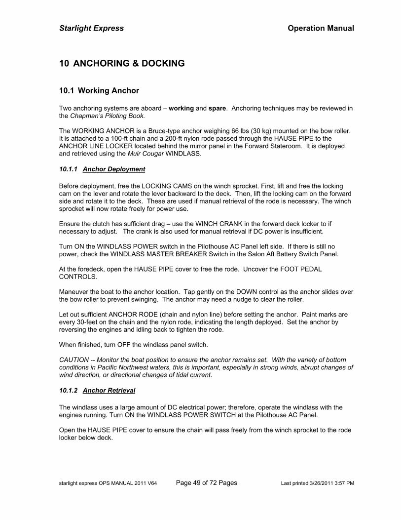
Starlight Express Operation Manual
starlight express OPS MANUAL 2011 V64 Page 49 of 72 Pages Last printed 3/26/2011 3:57 PM
10 ANCHORING & DOCKING
10.1 Working Anchor Two anchoring systems are aboard – working and spare. Anchoring techniques may be reviewed in the Chapman’s Piloting Book. The WORKING ANCHOR is a Bruce-type anchor weighing 66 lbs (30 kg) mounted on the bow roller. It is attached to a 100-ft chain and a 200-ft nylon rode passed through the HAUSE PIPE to the ANCHOR LINE LOCKER located behind the mirror panel in the Forward Stateroom. It is deployed and retrieved using the Muir Cougar WINDLASS.
10.1.1 Anchor Deployment Before deployment, free the LOCKING CAMS on the winch sprocket. First, lift and free the locking cam on the lever and rotate the lever backward to the deck. Then, lift the locking cam on the forward side and rotate it to the deck. These are used if manual retrieval of the rode is necessary. The winch sprocket will now rotate freely for power use. Ensure the clutch has sufficient drag – use the WINCH CRANK in the forward deck locker to if necessary to adjust. The crank is also used for manual retrieval if DC power is insufficient. Turn ON the WINDLASS POWER switch in the Pilothouse AC Panel left side. If there is still no power, check the WINDLASS MASTER BREAKER Switch in the Salon Aft Battery Switch Panel. At the foredeck, open the HAUSE PIPE cover to free the rode. Uncover the FOOT PEDAL CONTROLS. Maneuver the boat to the anchor location. Tap gently on the DOWN control as the anchor slides over the bow roller to prevent swinging. The anchor may need a nudge to clear the roller. Let out sufficient ANCHOR RODE (chain and nylon line) before setting the anchor. Paint marks are every 30-feet on the chain and the nylon rode, indicating the length deployed. Set the anchor by reversing the engines and idling back to tighten the rode. When finished, turn OFF the windlass panel switch. CAUTION -- Monitor the boat position to ensure the anchor remains set. With the variety of bottom conditions in Pacific Northwest waters, this is important, especially in strong winds, abrupt changes of wind direction, or directional changes of tidal current.
10.1.2 Anchor Retrieval The windlass uses a large amount of DC electrical power; therefore, operate the windlass with the engines running. Turn ON the WINDLASS POWER SWITCH at the Pilothouse AC Panel. Open the HAUSE PIPE cover to ensure the chain will pass freely from the winch sprocket to the rode locker below deck.
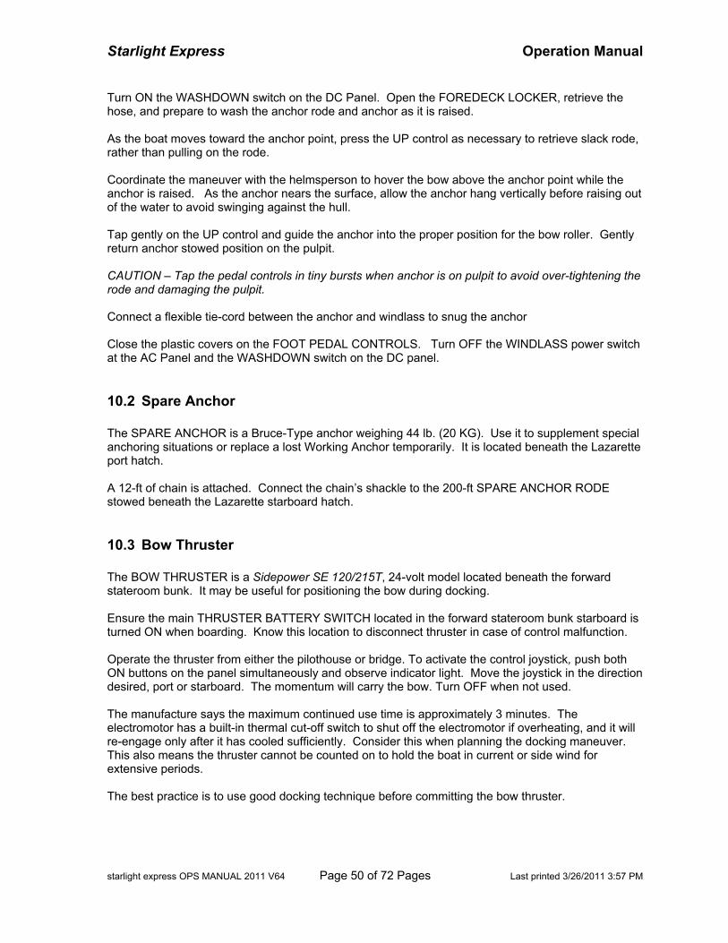
Starlight Express Operation Manual
starlight express OPS MANUAL 2011 V64 Page 50 of 72 Pages Last printed 3/26/2011 3:57 PM
Turn ON the WASHDOWN switch on the DC Panel. Open the FOREDECK LOCKER, retrieve the hose, and prepare to wash the anchor rode and anchor as it is raised. As the boat moves toward the anchor point, press the UP control as necessary to retrieve slack rode, rather than pulling on the rode. Coordinate the maneuver with the helmsperson to hover the bow above the anchor point while the anchor is raised. As the anchor nears the surface, allow the anchor hang vertically before raising out of the water to avoid swinging against the hull. Tap gently on the UP control and guide the anchor into the proper position for the bow roller. Gently return anchor stowed position on the pulpit. CAUTION – Tap the pedal controls in tiny bursts when anchor is on pulpit to avoid over-tightening the rode and damaging the pulpit. Connect a flexible tie-cord between the anchor and windlass to snug the anchor Close the plastic covers on the FOOT PEDAL CONTROLS. Turn OFF the WINDLASS power switch at the AC Panel and the WASHDOWN switch on the DC panel.
10.2 Spare Anchor The SPARE ANCHOR is a Bruce-Type anchor weighing 44 lb. (20 KG). Use it to supplement special anchoring situations or replace a lost Working Anchor temporarily. It is located beneath the Lazarette port hatch. A 12-ft of chain is attached. Connect the chain’s shackle to the 200-ft SPARE ANCHOR RODE stowed beneath the Lazarette starboard hatch.
10.3 Bow Thruster The BOW THRUSTER is a Sidepower SE 120/215T, 24-volt model located beneath the forward stateroom bunk. It may be useful for positioning the bow during docking. Ensure the main THRUSTER BATTERY SWITCH located in the forward stateroom bunk starboard is turned ON when boarding. Know this location to disconnect thruster in case of control malfunction. Operate the thruster from either the pilothouse or bridge. To activate the control joystick, push both ON buttons on the panel simultaneously and observe indicator light. Move the joystick in the direction desired, port or starboard. The momentum will carry the bow. Turn OFF when not used. The manufacture says the maximum continued use time is approximately 3 minutes. The electromotor has a built-in thermal cut-off switch to shut off the electromotor if overheating, and it will re-engage only after it has cooled sufficiently. Consider this when planning the docking maneuver. This also means the thruster cannot be counted on to hold the boat in current or side wind for extensive periods. The best practice is to use good docking technique before committing the bow thruster.
Starlight Express Operation Manual
starlight express OPS MANUAL 2011 V64 Page 51 of 72 Pages Last printed 3/26/2011 3:57 PM
Be aware of objects, small watercraft, or persons near the thruster. The thruster blades will draw objects into the tunnel.
10.4 Mooring Buoys The Washington State Park Sticker on the vessel starboard transom allows use of Marine parks docks and mooring buoys. Mooring buoys usually have a metal triangle on top with a metal ring. A printed plate provides the capacity information for the buoy. Before mooring, determine the rating capacity and the maximum boat length permitted on the mooring buoy. The metal ring is attached to the buoy’s chain and can usually be lifted upward to the boat to attach a mooring line. But, the chain is heavy -- a strong crewmember should assist in this task. The helmsman should maneuver from downwind or down current. Use two crewmembers at the bow, one with a boat hook and one to assist with a mooring line. The end of the mooring line should be secured to one of the bow cleats. As easy way to coordinate with helmsman is to have one crewmember point an arm continuously at the buoy. Through body language, the helmsman will know the buoy’s location in relation to the bow as it disappears from view. One crewmember hooks the metal ring and raises it. Another crewmember, threads the mooring line through the ring and secures the free end to an opposite bow cleat, forming a bridle with 10-feet slack from the buoy. In wind or current, use the special MOORING HOOK as a simpler way to gain a hold of the mooring buoy. The hook and attached mooring line (white) is located in the foredeck locker. Lead the loop end of the mooring line from below the pulpit, upward through the opening, and attach loop to a cleat. Hold the hook in position on the end of the boat pole with tension on the mooring line. Maneuver the boat to the buoy. Reach out, insert the hook end into the buoy’s metal ring, and set the hook. To retrieve hook, lift the bend of the hook with a boat pole. For overnight stays, supplement the mooring hook with a line through the ring and secured to boat cleat.
10.5 Stern Tie Using stern tie to shore is often necessary when the anchorage is crowded, when the swing space is limited, or when rotation around the anchor point is not desired. A 400-ft lightweight propylene line can be used for the stern-tie line. It is on a roll beneath the cockpit port hatch. In anchorages where stern tie mooring is common, metal rings may be found on the shore for stern lines. To set up easy retrieval upon departure, thread the free end of the propylene line through the shore ring and return the free end to the boat, doubling the line. Upon departure, retrieve line by releasing the free end from the boat and pulling through the ring. The 200-ft spare anchor rode can also be used as stern-tie line.

Starlight Express Operation Manual
starlight express OPS MANUAL 2011 V64 Page 52 of 72 Pages Last printed 3/26/2011 3:57 PM
BLANK PAGE
Starlight Express Operation Manual
starlight express OPS MANUAL 2011 V64 Page 53 of 72 Pages Last printed 3/26/2011 3:57 PM
11 DINGHY The DINGHY is a Rendova rigid inflatable boat (RIB) with 40-horsepower Honda 4-stroke motor. It has a capacity to carry 4-people. Dinghy and motor weigh about 750 pounds.
11.1 Launch The DAVIT BREAKER is located in the Salon aft battery switch panel and is normally ON. Plug the DAVIT CONTROL UNIT cord into the DAVIT WINCH CONTROL RECEPTACLE located on the masthead just forward of the davit. The DAVIT WINCH CONTROLLER is a hand-held unit attached to 8-foot cord and plug, is normally stored on the Pilothouse helm port shelf. WARNING -- After each use, disconnect the DAVIT CONTROL UNIT from the receptacle. If the handset becomes wet, it may short-circuit the handset causing the davit to operate ‘uncontrolled’. There will be severe strain on the davit, cable, and dinghy and damage will result. NOTE – A spare DAVIT WINCH CONTROLLER is located beneath the Pilothouse helm port seat. Install the aft drain plug located just below the motor. If already in place, turn ON the BILGE PUMP switch to remove the bilge water and unnecessary weight. CAUTION – If bilge water is not removed, the dinghy will not maintain an even keel when lifted. The water will re-locate to the bow and it will point downward haplessly and be difficult to launch. Release the three deck tie downs. If the deck stanchions are in place, remove them and stow them in beneath the Bridge seat. WARNING -- Before engaging the control, ensure the davit cable is on the davit roller and will run freely. Because the cable is lightweight, it tends to ride off the roller onto the shaft if the cable is slack. If it rides the shaft, there will be severe strain on the cable and risk of breakage! Keep tension on the cable when it is free and check the roller frequently. A plastic guide helps stay the cable. Carefully, nudge the hand switch to the IN position to begin lifting. Slowly lift the dingy clear of the deck and chocks. WARNING -- Do not make contact between hook and boom roller– there will be tremendous strain and damage will occur. Ensure good footing; the boat will list to port. Push the dinghy back and outward, rotating the davit boom outward. When the davit boom is nearly perpendicular to deck, rotate the dinghy parallel to the deck, bow pointing aft. Check clearance, and nudge the hand-switch to the OUT position to gently lower the dinghy, guiding it down the side. WARNING -- Allow no person to ride the dinghy or be positioned below it. Remove the lifting harness from the 3 positions on the dinghy. For safety, clip the three hooks back to the main ring to control loose gear. Move the dinghy to swim step or dock. Raise the cable, maintaining natural tension on the line. Rotate the davit boom inward. Use the cable hook or one of the short lifting harness hooks to secure the davit boom to the deck cleat.
Starlight Express Operation Manual
starlight express OPS MANUAL 2011 V64 Page 54 of 72 Pages Last printed 3/26/2011 3:57 PM
11.2 Operation
11.2.1 Pre-Checks Before operating, open the engine cover and check the oil with the motor level. Spare oil is located in the Cockpit portside cabinet. The 17-gallon tank is filled with Gasoline ONLY. DO NOT add oil to fuel. CAUTION – The most common problem is water in the fuel. Take measures to prevent water from entering the fuel tank during refueling and avoid ‘drowning’ the fuel cap when operating. Before first-use and often thereafter, inspect the fuel-water separator located beneath the seat. Rotate the drain valve, and drain completely. Close the separator valve and flush the hose by pushing-in on the ball valve while squeezing fuel through the primer bulb. If water enters the three carburetors, use a screwdriver to loosen the drain plug beneath each bowl (being very careful not to lose the screw) and flush the fuel bowls by pumping fuel through with the primer bulb. A 12-volt battery charger is stowed beneath the starboard bridge seat (red box) for battery charging if necessary. Plug into a 120-volt receptacle (one is located inside bridge entertainment cabinet), using an extension cord from the Electrical Tool Box (orange) located beneath the salon starboard seat.
11.2.2 Use Lower or raise the motor by pressing ‘Down’ or ‘UP’ on the MOTOR TILT rocker switch on the throttle handle, or on the side of the engine cover. Connect the fuel line to the motor securely. Squeeze the rubber primer to fill the carburetors. Ensure the throttle is in the NEUTRAL position. If the motor is cold, pull the CHOKE lever on the motor cover. Move the IDLE SPEED lever upward. Turn the MOTOR IGNITION KEY to crank. Back off the choke until the engine runs smoothly and the choke is no longer needed. Use the IDLE SPEED lever to maintain high rpm until the engine warms and operates smoothly. Then, return it to the downward (low speed) position – the THROTTLE lever will operate only when the lever is down. To move dingy forward, grab the THROTTLE lever, use the thumb to squeeze the handle release, and move the THROTTLE forward until the engine gear engages. To increase forward speed, push the throttle further forward. Return to neutral to disengage gear. To move backward, squeeze the handle release and move the throttle lever backward until gear engages. To increase backward speed, pull the throttle further backward. To apply motor TRIM, press on the UP/DOWN rocker switch on the throttle. . Use motor trim within safe limits. CAUTION -- Ensure crewmembers are trained properly in operation and safety. WA-State and Canadian Laws have minimum age limits that require personal certification for operating powered boats. Be aware of speed, sea conditions, and traffic.
Starlight Express Operation Manual
starlight express OPS MANUAL 2011 V64 Page 55 of 72 Pages Last printed 3/26/2011 3:57 PM
11.3 Retrieval To retrieve the dinghy, the procedure is reverse of deployment. WARNING -- Use the BILGE pump to remove the bilge water and remove extra gear to reduce unnecessary weight on the davit. Tilt the motor UPWARD slightly to avoid damage to the rear of the boat deck. Deploy the davit boom. Move the dinghy along the port side, pointing dinghy bow toward the boat stern, and tie loosely to a cleat Clip the lifting harness to the dinghy lifting eyes. Free the dinghy, a retrieve slack on the cable. Ensure harness is not entangled with motor control cables of fuel line. WARNING -- Before engaging the control, ensure the davit cable is on the davit roller and will run freely. Because the cable is lightweight, it tends to ride off the roller onto the shaft when cable is slack. If the cable rides the shaft, there will be severe strain on the cable! Keep natural tension on the cable and check the roller frequently. A plastic guide helps the cable stay on the roller. Ensure good footing -- the boat deck will list to portside during lifting. Lift slowly and check the dinghy harness and balance. Carefully raise the line hook within a foot from the boom tip. WARNING -- Do not make contact between hook and boom roller– there will be tremendous strain and damage will occur. Allow no person to be positioned below the dinghy. Rotate the bow inboard, point it across the deck, and make contact with the davit boom. Grab the dinghy rail and the sink rail and pull steadily and firmly (the dinghy is moving uphill), while rotating the dinghy bow toward the forward chock. Guide the dinghy hull to the rear chocks, checking clearance. Ensure the chock pads are faced properly. Lower until the hull rests firmly on the chocks, and relieve tension on the cable. Secure the dinghy with the 3 deck tie downs. Ensure the DINGHY KEY SWITCH and each accessory switch are in their OFF position to avoid battery discharge. Remove the DAVIT CONTROL unit from the plug and store in pilothouse. Do not leave unattended.
11.4 Equipment The following equipment is available for dinghy operation: Item Qty Location Remark VHF Radio 1 Console Console ELECTRONICS switch Depth/Fish Finder 1 Console Console ELECTRONICS switch Bilge Pump 1 Bilge Console BILGE Sw. Ensure OFF Navigation White Light 1 Beneath seat Plug into stb aft receptacle, Nav Lights Sw Life jackets 4 Beneath Seat Throwable Cushion 1 Seat Paddles 2 Strapped to Rails Insert pins into Scotty holders for rowing Paddles, spares 2 Beneath Seat Folding Anchor 1 Bow Locker Metal Stake 1 Bow Locker May pound into beach to secure boat line
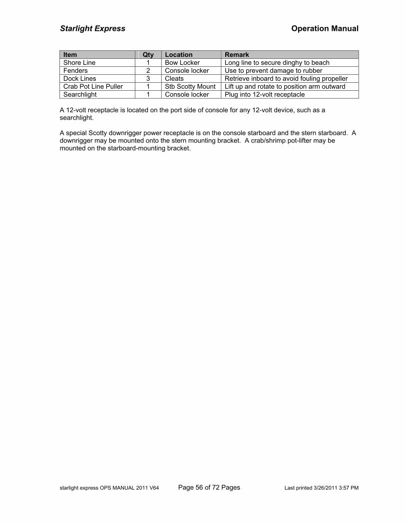
Starlight Express Operation Manual
starlight express OPS MANUAL 2011 V64 Page 56 of 72 Pages Last printed 3/26/2011 3:57 PM
Item Qty Location Remark Shore Line 1 Bow Locker Long line to secure dinghy to beach Fenders 2 Console locker Use to prevent damage to rubber Dock Lines 3 Cleats Retrieve inboard to avoid fouling propeller Crab Pot Line Puller 1 Stb Scotty Mount Lift up and rotate to position arm outward Searchlight 1 Console locker Plug into 12-volt receptacle
A 12-volt receptacle is located on the port side of console for any 12-volt device, such as a searchlight. A special Scotty downrigger power receptacle is on the console starboard and the stern starboard. A downrigger may be mounted onto the stern mounting bracket. A crab/shrimp pot-lifter may be mounted on the starboard-mounting bracket.
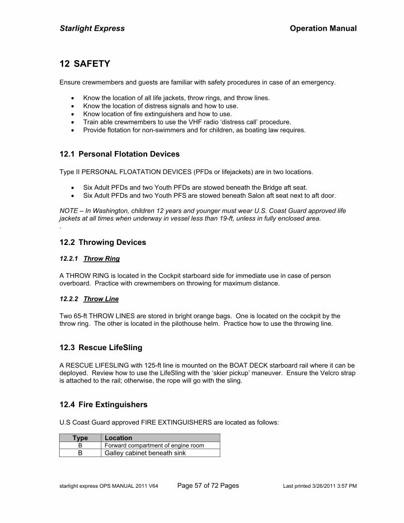
Starlight Express Operation Manual
starlight express OPS MANUAL 2011 V64 Page 57 of 72 Pages Last printed 3/26/2011 3:57 PM
12 SAFETY Ensure crewmembers and guests are familiar with safety procedures in case of an emergency.
• Know the location of all life jackets, throw rings, and throw lines. • Know the location of distress signals and how to use. • Know location of fire extinguishers and how to use. • Train able crewmembers to use the VHF radio ‘distress call’ procedure. • Provide flotation for non-swimmers and for children, as boating law requires.
12.1 Personal Flotation Devices Type II PERSONAL FLOATATION DEVICES (PFDs or lifejackets) are in two locations.
• Six Adult PFDs and two Youth PFDs are stowed beneath the Bridge aft seat. • Six Adult PFDs and two Youth PFS are stowed beneath Salon aft seat next to aft door.
NOTE – In Washington, children 12 years and younger must wear U.S. Coast Guard approved life jackets at all times when underway in vessel less than 19-ft, unless in fully enclosed area. .
12.2 Throwing Devices
12.2.1 Throw Ring A THROW RING is located in the Cockpit starboard side for immediate use in case of person overboard. Practice with crewmembers on throwing for maximum distance.
12.2.2 Throw Line Two 65-ft THROW LINES are stored in bright orange bags. One is located on the cockpit by the throw ring. The other is located in the pilothouse helm. Practice how to use the throwing line.
12.3 Rescue LifeSling A RESCUE LIFESLING with 125-ft line is mounted on the BOAT DECK starboard rail where it can be deployed. Review how to use the LifeSling with the ‘skier pickup’ maneuver. Ensure the Velcro strap is attached to the rail; otherwise, the rope will go with the sling.
12.4 Fire Extinguishers U.S Coast Guard approved FIRE EXTINGUISHERS are located as follows:
Type Location B Forward compartment of engine room B Galley cabinet beneath sink
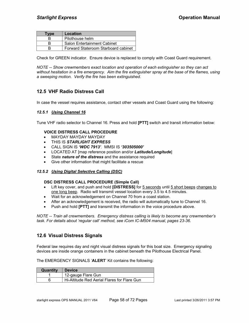
Starlight Express Operation Manual
starlight express OPS MANUAL 2011 V64 Page 58 of 72 Pages Last printed 3/26/2011 3:57 PM
Type Location B Pilothouse helm B Salon Entertainment Cabinet B Forward Stateroom Starboard cabinet
Check for GREEN indicator. Ensure device is replaced to comply with Coast Guard requirement. NOTE -- Show crewmembers exact location and operation of each extinguisher so they can act without hesitation in a fire emergency. Aim the fire extinguisher spray at the base of the flames, using a sweeping motion. Verify the fire has been extinguished.
12.5 VHF Radio Distress Call In case the vessel requires assistance, contact other vessels and Coast Guard using the following:
12.5.1 Using Channel 16 Tune VHF radio selector to Channel 16. Press and hold [PTT] switch and transit information below:
VOICE DISTRESS CALL PROCEDURE • MAYDAY MAYDAY MAYDAY • THIS IS STARLIGHT EXPRESS • CALL SIGN IS ‘WDC 7913’. MMSI IS ‘303505000’ • LOCATED AT [map reference position and/or Latitude/Longitude] • State nature of the distress and the assistance required • Give other information that might facilitate a rescue
12.5.2 Using Digital Selective Calling (DSC)
DSC DISTRESS CALL PROCEDURE (Simple Call) • Lift key cover, and push and hold [DISTRESS] for 5 seconds until 5 short beeps changes to
one long beep. Radio will transmit vessel location every 3.5 to 4.5 minutes. • Wait for an acknowledgement on Channel 70 from a coast station. • After an acknowledgement is received, the radio will automatically tune to Channel 16. • Push and hold [PTT] and transmit the information in the voice procedure above.
NOTE -- Train all crewmembers. Emergency distress calling is likely to become any crewmember’s task. For details about ‘regular call’ method, see iCom IC-M504 manual, pages 23-36.
12.6 Visual Distress Signals Federal law requires day and night visual distress signals for this boat size. Emergency signaling devices are inside orange containers in the cabinet beneath the Pilothouse Electrical Panel. The EMERGENCY SIGNALS ‘ALERT’ Kit contains the following:
Quantity Device 1 12-gauge Flare Gun 6 Hi-Altitude Red Aerial Flares for Flare Gun
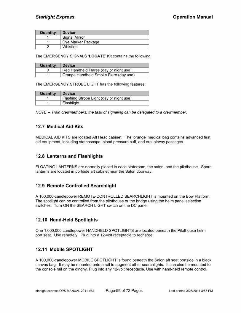
Starlight Express Operation Manual
starlight express OPS MANUAL 2011 V64 Page 59 of 72 Pages Last printed 3/26/2011 3:57 PM
Quantity Device 1 Signal Mirror 1 Dye Marker Package 2 Whistles
The EMERGENCY SIGNALS ‘LOCATE’ Kit contains the following:
Quantity Device 3 Red Handheld Flares (day or night use) 1 Orange Handheld Smoke Flare (day use)
The EMERGENCY STROBE LIGHT has the following features:
Quantity Device 1 Flashing Strobe Light (day or night use) 1 Flashlight
NOTE -- Train crewmembers; the task of signaling can be delegated to a crewmember.
12.7 Medical Aid Kits MEDICAL AID KITS are located Aft Head cabinet. The ‘orange’ medical bag contains advanced first aid equipment, including stethoscope, blood pressure cuff, and oral airway passages.
12.8 Lanterns and Flashlights FLOATING LANTERNS are normally placed in each stateroom, the salon, and the pilothouse. Spare lanterns are located in portside aft cabinet near the Salon doorway.
12.9 Remote Controlled Searchlight A 100,000-candlepower REMOTE-CONTROLLED SEARCHLIGHT is mounted on the Bow Platform. The spotlight can be controlled from the pilothouse or the bridge using the helm panel selection switches. Turn ON the SEARCH LIGHT switch on the DC panel.
12.10 Hand-Held Spotlights One 1,000,000 candlepower HANDHELD SPOTLIGHTS are located beneath the Pilothouse helm port seat. Use remotely. Plug into a 12-volt receptacle to recharge.
12.11 Mobile SPOTLIGHT A 100,000-candlepower MOBILE SPOTLIGHT is found beneath the Salon aft seat portside in a black canvas bag. It may be mounted onto a rail to augment other searchlights. It can also be mounted to the console rail on the dinghy. Plug into any 12-volt receptacle. Use with hand-held remote control.
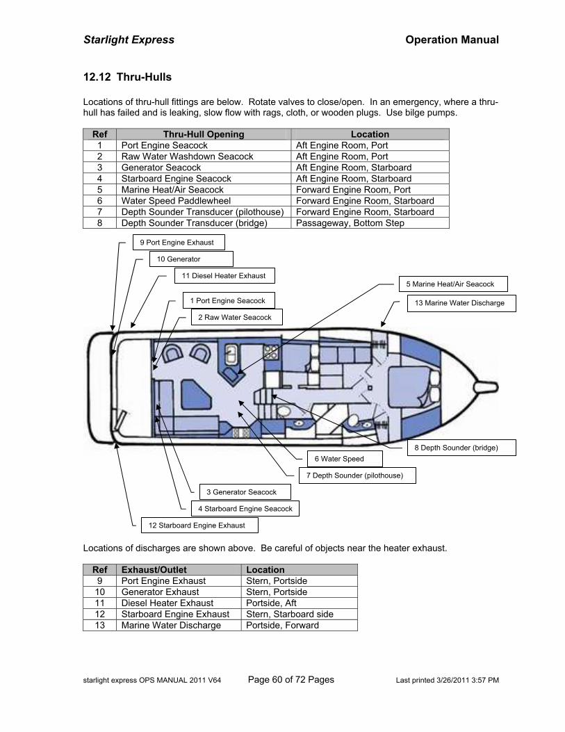
Starlight Express Operation Manual
starlight express OPS MANUAL 2011 V64 Page 60 of 72 Pages Last printed 3/26/2011 3:57 PM
12.12 Thru-Hulls Locations of thru-hull fittings are below. Rotate valves to close/open. In an emergency, where a thru-hull has failed and is leaking, slow flow with rags, cloth, or wooden plugs. Use bilge pumps.
Ref Thru-Hull Opening Location 1 Port Engine Seacock Aft Engine Room, Port 2 Raw Water Washdown Seacock Aft Engine Room, Port 3 Generator Seacock Aft Engine Room, Starboard 4 Starboard Engine Seacock Aft Engine Room, Starboard 5 Marine Heat/Air Seacock Forward Engine Room, Port 6 Water Speed Paddlewheel Forward Engine Room, Starboard 7 Depth Sounder Transducer (pilothouse) Forward Engine Room, Starboard 8 Depth Sounder Transducer (bridge) Passageway, Bottom Step
Locations of discharges are shown above. Be careful of objects near the heater exhaust.
Ref Exhaust/Outlet Location 9 Port Engine Exhaust Stern, Portside 10 Generator Exhaust Stern, Portside 11 Diesel Heater Exhaust Portside, Aft 12 Starboard Engine Exhaust Stern, Starboard side 13 Marine Water Discharge Portside, Forward
4 Starboard Engine Seacock
1 Port Engine Seacock
2 Raw Water Seacock
3 Generator Seacock
5 Marine Heat/Air Seacock
6 Water Speed
7 Depth Sounder (pilothouse)
9 Port Engine Exhaust
10 Generator
13 Marine Water Discharge
11 Diesel Heater Exhaust
12 Starboard Engine Exhaust
8 Depth Sounder (bridge)
Starlight Express Operation Manual
starlight express OPS MANUAL 2011 V64 Page 61 of 72 Pages Last printed 3/26/2011 3:57 PM
13 NAVIGATION
13.1 Charts
13.1.1 Electronic Chart The Navionics Platinum 913P package on the each Raymarine Multifunction Display contains territory from Puget Sound to Queen Charlotte Sound, including Juan de Fuca Strait, Strait of Georgia, Johnstone Strait, Queen Charlotte Strait, and Cape Flattery. Features include satellite photo overlay, panoramic pictures, 3-D underwater charts, port services, points of interest, tides and current, and Coast Pilot books. CAUTION -- Electronic charts add to safety and enjoyment, but do not rely. Use multiple sources in unfamiliar waters, including current official government charts. Practice traditional navigation skills.
13.1.2 Official Charts OFFICIAL CHARTS for Puget Sound, San Juan Islands, and Gulf Islands northward to Port Hardy are located in drawer beneath the Pilothouse starboard chart table. See Appendix B for list.
13.1.3 Cruising Atlas Use the CRUISING ATLAS as a ‘planning chart’. While not suitable for detailed navigation, it may be easier to use at the helm. When in doubt, refer to the Official Charts.
13.1.4 Chart Books A CHART BOOK for ‘Jervis Inlet & Desolation Sound’, as well as separate, folded charts for the ‘Sunshine Coast’ of British Columbia, ‘Strait of Georgia’, ‘Discovery Islands’, ‘Broughton Islands’, ‘Johnstone Strait, and ‘Queen Charlotte Strait’ are in the chart drawer. See Appendix B for list.
13.2 Tide and Current Tables The ‘Ports and Passes’ TIDES, CURRENTS, AND CHARTS book is located at the Pilothouse navigation table. It contains tide and current information from Olympia in lower Puget Sound to Johnstone Strait in northern Vancouver Island. It is also packed with useful information about marine weather, area restrictions, fuel locations, vessel services, and supplies. The ‘Ports and Passes’ CURRENT ATLAS TABLES book is the annual supplement for use with the CANADIAN CURRENT ATLAS. It is found at the Pilothouse aft cabinet above the seat.
13.3 Cruising Guides Guidebooks for marinas, anchorages, and boating points of interest are found in the Pilothouse aft cabinet above the seat. These include the Waggoner Cruising Guide (covering all the Pacific
Starlight Express Operation Manual
starlight express OPS MANUAL 2011 V64 Page 62 of 72 Pages Last printed 3/26/2011 3:57 PM
Northwest), Gunkholing in the San Juans, Gulf Islands Guide, Desolation Sound Guide, South Puget Sound Guide. When planning a passage, it is a good idea to make alternate plans in case of delay, inclement weather, comfort, or safety.
13.4 Navigation Tools Two BINOCULARS are located in the Pilothouse helm. PLOTTING RULER, DIVIDER, and MAGNIFIER are located at the Pilothouse navigation station.
Starlight Express Operation Manual
starlight express OPS MANUAL 2011 V64 Page 63 of 72 Pages Last printed 3/26/2011 3:57 PM
14 DOCUMENTS
14.1 Vessel Documents The VESSEL DOCUMENTS include papers for boat identification, registration, and licensing. These are normally found in the AYC Charter Manual; otherwise they are found in Boat Documents white binder in the cabinet beneath the Pilothouse electrical panel. Documents include:
• Coast Guard 'Documented Ship' Official Certificate (Official Number) • FCC Ships Radio Station License • US Customs Annual Registration (decal on Salon aft window) • Washington State Parks Registration (decal on Salon aft hull) • Washington DoR Registration (boat) • Washington State Boat Registration (dinghy)
14.2 Border Crossing When cruising into Canada, the vessel and the passengers are required to clear through a Canadian Customs ‘Reporting Site’. Information on reporting sites, phone numbers, and procedure for clearing Canadian Customs can be found in the Ports and Passes Tide and Current book. NOTE -- The frequently used Canadian reporting sites nearby are Bedwell Harbor (May-Sep 8AM to 10PM), Port Sidney, or Port Victoria Customs Wharf. Upon returning to the United States, the vessel and the passengers are required to clear through a United States Customs and Border Protection (CBP) ‘Designated Port of Entry’. Information on locations, telephone numbers, and hours of operation, and procedure for clearing US CBP is found in the Ports and Passes Tide and Current book. The annual US CUSTOMS Decal is located on the aft Salon window, where it can be easily seen from the rear. A document with the decal number is also found in the vessel documents. NOTE -- The most frequently used US ports of entry in the San Juan Island are Roche Harbor (seasonal, call for appointment), Friday Harbor (8AM to 5PM), Anacortes (8AM to 5PM), Bellingham (7AM to 6PM), or After Hour 800-562-5943. To avoid delay, have the vessel documents, all passenger passports, and paper and pencil handy to copy customs information, before meeting or calling customs officials.
• Vessel Official Number = 1137711 • Vessel Name = Starlight Express • Vessel Length = 54 feet • Vessel Make/Type = Bayliner 4788 Powerboat • Customs Decal Number (US reentry) (located on salon aft, copy in vessel doc book) • CA Customs Entry Number and Date (US reentry) (obtained from Canadian Customs)
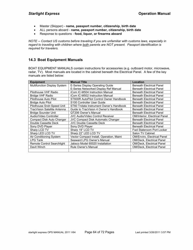
Starlight Express Operation Manual
starlight express OPS MANUAL 2011 V64 Page 64 of 72 Pages Last printed 3/26/2011 3:57 PM
• Master (Skipper) - name, passport number, citizenship, birth date • ALL persons aboard - name, passport number, citizenship, birth date • Response to questions - food, liquor, or firearms aboard
NOTE -- Contact US customs before traveling if you are unfamiliar with customs laws, especially in regard to traveling with children where both parents are NOT present. Passport identification is required for travelers.
14.3 Boat Equipment Manuals BOAT EQUIPMENT MANUALS contain instructions for accessories (e.g. outboard motor, microwave, radar, TV). Most manuals are located in the cabinet beneath the Electrical Panel. A few of the key manuals are listed below:
Equipment Manual Title Location Multifunction Display System E-Series Display Operating Guide
E-Series Networked Display Ref Manual Beneath Electrical Panel Beneath Electrical Panel
Pilothouse VHF Radio iCom IC-M504 Instruction Manual Beneath Electrical Panel Bridge VHF Radio iCom IC-M502 Instruction Manual Beneath Electrical Panel Pilothouse Auto Pilot ST600R AutoPilot Control Owner Handbook Beneath Electrical Panel Bridge Auto Pilot S100 Controller User Guide Beneath Electrical Panel Pilothouse Sndr-Speed Unit ST60 Tridata Instrument Owner’s Handbook Beneath Electrical Panel TracVision Satellite Antenna Guide to TracVision 4 Owner’s Handbook Beneath Electrical Panel Bridge Sounder Unit QT206 Owner’s Manual Beneath Electrical Panel Audio/Video Controller JVC Audio/Video Control Receiver OM/Interior, Electrical Panel Compact Disk Auto Changer JVC Compact Disk Automatic Changer Beneath Electrical Panel Double Cassette Deck JVC Double Cassette Deck Beneath Electrical Panel Sony DVD Player Sony DVD Player Beneath Electrical Panel Sharp LCD TV Sharp 19” LCD TV Fwd Stateroom Port Locker Sharp LED LCD TV Sharp 22” LED LCD TV Salon TV Cabinet Air Conditioning System Vector Compact Install, Operation, Maint OM/Enviro, Electrical Panel LPG Tank Seaward LPG Owner’s Manual OM/Deck, Electrical Panel Remote Control Searchlight Jabsco Model 60020 Installation OM/Deck, Electrical Panel Davit Winch Rule Owner’s Manual OM/Deck, Electrical Panel
Starlight Express Operation Manual
starlight express OPS MANUAL 2011 V64 Page 65 of 72 Pages Last printed 3/26/2011 3:57 PM
15 CLEANING
15.1 Waste Management Plan All crew members and passengers must be briefed on the vessel’s Solid Waste Management Plan to comply with US Coast Guard regulation.
WASTE MANAGEMENT PLAN for Starlight Express
Person in Charge: Master of Vessel
Solid Waste Management Procedures as Referenced Below:
All the garbage generated on the vessel is put in a garbage bag and disposed of in the trash containers at the harbor at the end of each trip or is given to the tender vessel to shore for disposal. All crew members have been oriented to the requirements of MARPOL ANNEX V by captain, and all new crew are specifically shown the MARPOL V placard and told to keep all refuse stowed on board. Passenger orientation to the vessel includes being shown the location of trash receptacles and mention of refuse discharge regulations.
15.2 Cleaning Supplies Cleaning supplies are located under the Galley sink or in the Head cabinets. DO NOT use ‘steel wool’ or metal abrasive scrubbers on the metal surfaces, sinks, and galley range - those materials will ‘certainly’ scratch those surfaces. Vinyl can only be cleaned with vinyl cleaner.
15.3 Vacuum Cleaner The CENTRAL VACUUM CLEANER and hose accessories are located in the starboard compartment in the passageway behind the Plexiglas panels. Turn ON the Vacuum Cleaner switch on the Pilothouse AC panel. The vacuum will turn ON automatically when the hose is plugged into the intake hole on the vacuum cleaner.
15.4 Washer/Dryer The WASHER/DRYER is located in the port cabinet in the passageway. Laundry soap is located in the Aft Head cabinet
• Turn ON the Washer/Dryer switch on the Pilothouse AC panel.
Starlight Express Operation Manual
starlight express OPS MANUAL 2011 V64 Page 66 of 72 Pages Last printed 3/26/2011 3:57 PM
• Pull open the detergent tray on the left side and add 1-2 tablespoons of detergent into Dispenser B (Dispenser A for cold-cold cycle). Close the tray.
• Select Wash Cycle on the right dial. Select wash water temperature on the left dial. If drying
is desired, select drying time on the center dial. Select temperature and spin on buttons.
• Press the ON button to start. The unit will do the wash cycle first, and if drying time was selected, it will do drying cycle automatically. Washing and drying can be independent.
15.5 Deck Cleaning Gear A DECK BRUSH is located on the cockpit transom. . Two 50-ft WATER Hoses are located beneath the Lazarette portside hatch. ‘Yellow’ plastic nozzles are found on hoses or spares stowed in the Salon starboard cabinet. BUCKET, WASH MITT, and SPONGE are usually located on the Boat Deck.
15.6 Fresh Water Wash Down A 15-foot coiled HOSE is located in the Salon cabinet portside and is connected to the FRESH WATER WASHDOWN FAUCET. The Cockpit shower faucet on the cockpit transom can be used as a hot water source if desired.
15.7 Raw Water Wash Down Two RAW WATER wash down outlets are available, one at the Foredeck and one in the Cockpit. In the Cockpit starboard cabinet, a 5-ft HOSE is connected to the AFT RAW WATER WASHDOWN FAUCET. In the foredeck locker is a 15-ft coiled HOSE is connected to the FORWARD RAW WATER WASHDOWN FAUCET. Turn ON the WASHDOWN switch on the Pilothouse DC panel. CAUTION -- Turn OFF the panel switch when not used to prevent pump damage.
Starlight Express Operation Manual
starlight express OPS MANUAL 2011 V64 Page 67 of 72 Pages Last printed 3/26/2011 3:57 PM
16 RECREATIONAL EQUIPMENT
16.1 Barbeque The BARBECUE (Magma ‘Newport’ Model) is mounted on the starboard rail on the boat deck. Ensure flammable materials are not near the barbecue when in use. Normally, the propane tank valve in the PROPANE LOCKER is OPEN. Turn ON the ENTERTAINMENT CENTER #1 on the DC Panel. Then turn on the PROPANE Switch on the panel next to barbeque. Finally, push-in the control knob, and turn slightly (ignition position). Press the barbeque ignition button to light (the flame is very low and quiet). Turning the knob counter-clockwise will reduce the flame. To turn off, turn clockwise until the knob pops outward. If the ignition button does not ignite the burner, use matches. The barbecue generates lots of heat. Cooking greases may burn. CAUTION – When finished, ensure the BARBECUE control knob is turned OFF and the PROPANE switch is OFF.
16.2 Deck Chairs Two folding frame white-canvas deck chairs are stowed normally in the cockpit portside near doorway. Use the bungee cord to secure when not in use. Four folding blue-canvas chairs are stowed beneath the salon aft seat. Two folding canvas stools and a small folding canvas table are stowed there also.
16.3 Cooler A 155-qt Yeti Cooler is in the cockpit for additional food storage. It is molded construction, very durable, and is highly insulated. The lid may be pad-locked to meet ‘bear-proof’ certification. It is for ideal for extra beverages and foodstuff. It doubles as an outdoor seat bench.
16.4 Crab Gear Two sets of CRAB TRAPS, LINES, and FLOATS are stowed on the flybridge deck in a black canvas bag and a covered white bucket. BAIT CONTAINERS are stowed beneath the starboard seat. Assemble the float – flag-pole-buoy-pole-weight. Clip line securely to the float assembly and to the crab trap harness. Fill the bait containers and suspend containers inside trap. Crab bait is available from marina stores (or try own, for example, chicken backs).
Starlight Express Operation Manual
starlight express OPS MANUAL 2011 V64 Page 68 of 72 Pages Last printed 3/26/2011 3:57 PM
Deploy the traps in water less than 60-ft (maximum length of line). After a waiting period, retrieve the trap. Measure crabs using the CRAB MEASURING GAUGE normally found in the bucket. Keep male crabs of proper size, greater than 6-1/4”. After use, rinse gear with fresh water. To learn more about crabbing, refer to the book How to Catch Crab found on the Pilothouse aft cabinet.
16.5 Clam Gear A CLAM SHOVEL and HAND RAKE are stowed beneath the salon aft seat. Rinse with fresh water and dry thoroughly before re-stowing.
16.6 Fishing Gear FISHING POLES may be stowed in the pole holders on the bridge behind the seat. One Scotty electric DOWNRIGGER (Depthpower 1106 Longarm) is stowed beneath the starboard bridge seat, along with mounting equipment to mount on corners of the boat cockpit. CAUTION -- Experienced users ONLY should use downrigger equipment. Set up the downrigger in the cockpit.
• Mounting Bracket – Remove lines from the port and/or starboard hawse opening on the rail of the cockpit corner. If necessary retie lines to stern cleats. Guide the four bolts of the custom MOUNTING BRACKET ASSEMBLY into the opening. Beneath the rail, align back plate with white pads facing up against the bottom of the rail. Tighten with four wing nuts.
• Pedestal Mount – Orient the PEDESTAL MOUNT so the lever is facing inboard. Insert the
four knurled knob screws and tighten to MOUNTING BRACKET.
• Downrigger Unit – On left side of the DOWNRIGGER base, remove the red-colored base bolt. Place unit on the pedestal, align the base holes to the TILT UP BRACKET, and insert the red-colored base bolt from left (pushing completely through base), and tighten bolt.
• Power Receptacle. Plug the power cord into the RECEPTACLE beneath the rail. Rotate
the cord plug until prongs align, then push in and rotate clockwise slightly to lock. Test power to the unit by short taps on the GREEN power button. There is no other switch.
Follow good practice when using downrigger.
• Keep wire tight. Slack may form kinks or wire may wrap spool, causing damage. • Keep fingers away from the underside of the downrigger base, the spool, and the wire. • Lower the ball weight while boat is in forward motion to avoid tangle with props and rudder. • Bring gear toward you when retrieving weights or resetting release clips. Avoid leaning out –
an unexpected boat motion may send you overboard. • Remove the ball weight when downrigger is unattended. Secure ball in the ball carrier. • Use the red lock lever to secure the downrigger upright, or rotate the boom parallel to the rail. • Keep a pair of wire cutters handy to cut away snagged lines if necessary. • Keep a good bend in fishing rod. When fish hits, a bent rod will take up line as clip releases.
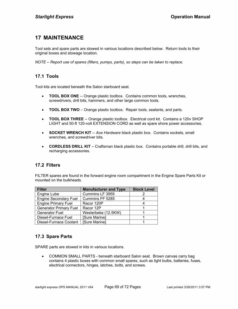
Starlight Express Operation Manual
starlight express OPS MANUAL 2011 V64 Page 69 of 72 Pages Last printed 3/26/2011 3:57 PM
17 MAINTENANCE Tool sets and spare parts are stowed in various locations described below. Return tools to their original boxes and stowage location. NOTE – Report use of spares (filters, pumps, parts), so steps can be taken to replace.
17.1 Tools Tool kits are located beneath the Salon starboard seat.
• TOOL BOX ONE -- Orange plastic toolbox. Contains common tools, wrenches, screwdrivers, drill bits, hammers, and other large common tools.
• TOOL BOX TWO – Orange plastic toolbox. Repair tools, sealants, and parts.
• TOOL BOX THREE -- Orange plastic toolbox. Electrical cord kit. Contains a 120v SHOP
LIGHT and 50-ft 120-volt EXTENSION CORD as well as spare shore power accessories.
• SOCKET WRENCH KIT -- Ace Hardware black plastic box. Contains sockets, small wrenches, and screwdriver bits.
• CORDLESS DRILL KIT – Craftsman black plastic box. Contains portable drill, drill bits, and
recharging accessories.
17.2 Filters FILTER spares are found in the forward engine room compartment in the Engine Spare Parts Kit or mounted on the bulkheads. Filter Manufacturer and Type Stock Level Engine Lube Cummins LF 3959 2 Engine Secondary Fuel Cummins FF 5285 4 Engine Primary Fuel Racor 120P 4 Generator Primary Fuel Racor 12P 1 Generator Fuel Westerbeke (12.5KW) 1 Diesel-Furnace Fuel [Sure Marine] 1 Diesel-Furnace Coolant [Sure Marine] 1
17.3 Spare Parts SPARE parts are stowed in kits in various locations.
• COMMON SMALL PARTS - beneath starboard Salon seat. Brown canvas carry bag contains 4 plastic boxes with common small spares, such as light bulbs, batteries, fuses, electrical connectors, hinges, latches, bolts, and screws.
Starlight Express Operation Manual
starlight express OPS MANUAL 2011 V64 Page 70 of 72 Pages Last printed 3/26/2011 3:57 PM
• ENGINE SPARE PARTS - forward engine room. Blue plastic box contains oil filter wrench, belts, raw water impellers, and common engine and generator maintenance spares.
• PLUMBING SPARE PARTS – engine room starboard forward of sanitation holding tank.
Boxes contain spare freshwater pump, macerator pump, bilge pumps, and toilet replacement parts.
17.4 Fluid Cleanup OIL SORB sheets are located in the forward engine room wedge against the water heater. Oil sorbs are located beneath each engine to detect and trap fluid leakage. Check periodically to detect unusual conditions. An oil sorb is placed in the lazarette bilge drainage, forward of the generator to trap oil or fuel leakage coming from the lazarette. Wiping RAGS and cloth towels are stowed beneath the mid-stateroom bunk, forward locker.
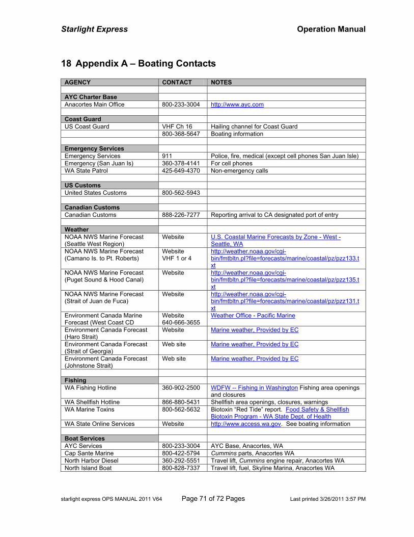
Starlight Express Operation Manual
starlight express OPS MANUAL 2011 V64 Page 71 of 72 Pages Last printed 3/26/2011 3:57 PM
18 Appendix A – Boating Contacts
AGENCY CONTACT NOTES AYC Charter Base Anacortes Main Office 800-233-3004 http://www.ayc.com Coast Guard US Coast Guard VHF Ch 16 Hailing channel for Coast Guard 800-368-5647 Boating information Emergency Services Emergency Services 911 Police, fire, medical (except cell phones San Juan Isle) Emergency (San Juan Is) 360-378-4141 For cell phones WA State Patrol 425-649-4370 Non-emergency calls US Customs United States Customs 800-562-5943 Canadian Customs Canadian Customs 888-226-7277 Reporting arrival to CA designated port of entry Weather NOAA NWS Marine Forecast (Seattle West Region)
Website
U.S. Coastal Marine Forecasts by Zone - West - Seattle, WA
NOAA NWS Marine Forecast (Camano Is. to Pt. Roberts)
Website VHF 1 or 4
http://weather.noaa.gov/cgi-bin/fmtbltn.pl?file=forecasts/marine/coastal/pz/pzz133.txt
NOAA NWS Marine Forecast (Puget Sound & Hood Canal)
Website http://weather.noaa.gov/cgi-bin/fmtbltn.pl?file=forecasts/marine/coastal/pz/pzz135.txt
NOAA NWS Marine Forecast (Strait of Juan de Fuca)
Website http://weather.noaa.gov/cgi-bin/fmtbltn.pl?file=forecasts/marine/coastal/pz/pzz131.txt
Environment Canada Marine Forecast (West Coast CD
Website 640-666-3655
Weather Office - Pacific Marine
Environment Canada Forecast (Haro Strait)
Website
Marine weather, Provided by EC
Environment Canada Forecast (Strait of Georgia)
Web site Marine weather, Provided by EC
Environment Canada Forecast (Johnstone Strait)
Web site
Marine weather, Provided by EC
Fishing WA Fishing Hotline 360-902-2500 WDFW -- Fishing in Washington Fishing area openings
and closures WA Shellfish Hotline 866-880-5431 Shellfish area openings, closures, warnings WA Marine Toxins 800-562-5632 Biotoxin “Red Tide” report. Food Safety & Shellfish
Biotoxin Program - WA State Dept. of Health WA State Online Services Website http://www.access.wa.gov. See boating information Boat Services AYC Services 800-233-3004 AYC Base, Anacortes, WA Cap Sante Marine 800-422-5794 Cummins parts, Anacortes WA North Harbor Diesel 360-292-5551 Travel lift, Cummins engine repair, Anacortes WA North Island Boat 800-828-7337 Travel lift, fuel, Skyline Marina, Anacortes WA
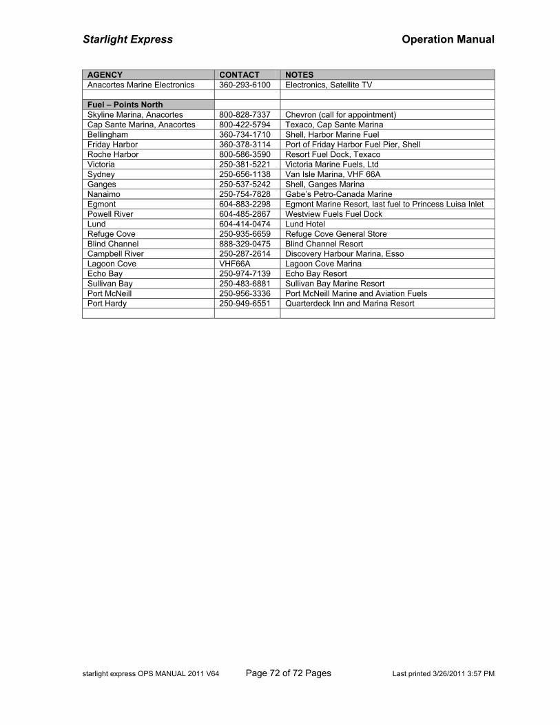
Starlight Express Operation Manual
starlight express OPS MANUAL 2011 V64 Page 72 of 72 Pages Last printed 3/26/2011 3:57 PM
AGENCY CONTACT NOTES Anacortes Marine Electronics 360-293-6100 Electronics, Satellite TV Fuel – Points North Skyline Marina, Anacortes 800-828-7337 Chevron (call for appointment) Cap Sante Marina, Anacortes 800-422-5794 Texaco, Cap Sante Marina Bellingham 360-734-1710 Shell, Harbor Marine Fuel Friday Harbor 360-378-3114 Port of Friday Harbor Fuel Pier, Shell Roche Harbor 800-586-3590 Resort Fuel Dock, Texaco Victoria 250-381-5221 Victoria Marine Fuels, Ltd Sydney 250-656-1138 Van Isle Marina, VHF 66A Ganges 250-537-5242 Shell, Ganges Marina Nanaimo 250-754-7828 Gabe’s Petro-Canada Marine Egmont 604-883-2298 Egmont Marine Resort, last fuel to Princess Luisa Inlet Powell River 604-485-2867 Westview Fuels Fuel Dock Lund 604-414-0474 Lund Hotel Refuge Cove 250-935-6659 Refuge Cove General Store Blind Channel 888-329-0475 Blind Channel Resort Campbell River 250-287-2614 Discovery Harbour Marina, Esso Lagoon Cove VHF66A Lagoon Cove Marina Echo Bay 250-974-7139 Echo Bay Resort Sullivan Bay 250-483-6881 Sullivan Bay Marine Resort Port McNeill 250-956-3336 Port McNeill Marine and Aviation Fuels Port Hardy 250-949-6551 Quarterdeck Inn and Marina Resort
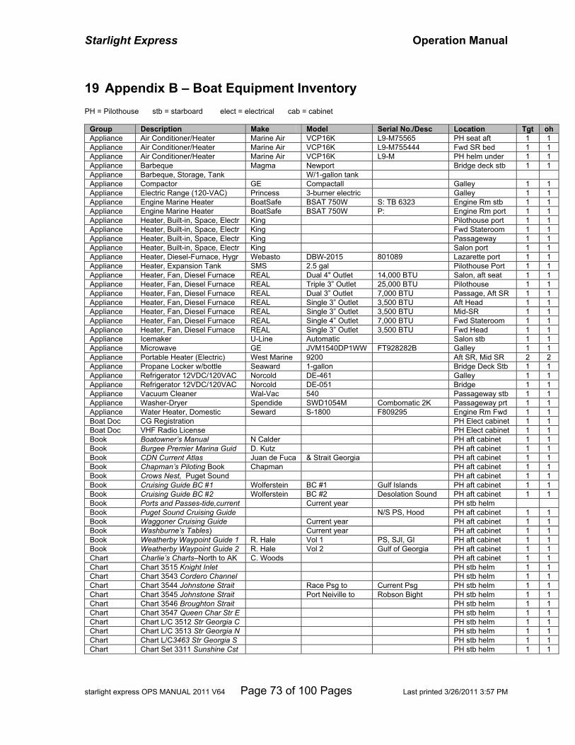
Starlight Express Operation Manual
starlight express OPS MANUAL 2011 V64 Page 73 of 100 Pages Last printed 3/26/2011 3:57 PM
19 Appendix B – Boat Equipment Inventory PH = Pilothouse stb = starboard elect = electrical cab = cabinet
Group Description Make Model Serial No./Desc Location Tgt oh Appliance Air Conditioner/Heater Marine Air VCP16K L9-M75565 PH seat aft 1 1 Appliance Air Conditioner/Heater Marine Air VCP16K L9-M755444 Fwd SR bed 1 1 Appliance Air Conditioner/Heater Marine Air VCP16K L9-M PH helm under 1 1 Appliance Barbeque Magma Newport Bridge deck stb 1 1 Appliance Barbeque, Storage, Tank W/1-gallon tank Appliance Compactor GE Compactall Galley 1 1 Appliance Electric Range (120-VAC) Princess 3-burner electric Galley 1 1 Appliance Engine Marine Heater BoatSafe BSAT 750W S: TB 6323 Engine Rm stb 1 1 Appliance Engine Marine Heater BoatSafe BSAT 750W P: Engine Rm port 1 1 Appliance Heater, Built-in, Space, Electr King Pilothouse port 1 1 Appliance Heater, Built-in, Space, Electr King Fwd Stateroom 1 1 Appliance Heater, Built-in, Space, Electr King Passageway 1 1 Appliance Heater, Built-in, Space, Electr King Salon port 1 1 Appliance Heater, Diesel-Furnace, Hygr Webasto DBW-2015 801089 Lazarette port 1 1 Appliance Heater, Expansion Tank SMS 2.5 gal Pilothouse Port 1 1 Appliance Heater, Fan, Diesel Furnace REAL Dual 4" Outlet 14,000 BTU Salon, aft seat 1 1 Appliance Heater, Fan, Diesel Furnace REAL Triple 3” Outlet 25,000 BTU Pilothouse 1 1 Appliance Heater, Fan, Diesel Furnace REAL Dual 3” Outlet 7,000 BTU Passage, Aft SR 1 1 Appliance Heater, Fan, Diesel Furnace REAL Single 3” Outlet 3,500 BTU Aft Head 1 1 Appliance Heater, Fan, Diesel Furnace REAL Single 3” Outlet 3,500 BTU Mid-SR 1 1 Appliance Heater, Fan, Diesel Furnace REAL Single 4” Outlet 7,000 BTU Fwd Stateroom 1 1 Appliance Heater, Fan, Diesel Furnace REAL Single 3” Outlet 3,500 BTU Fwd Head 1 1 Appliance Icemaker U-Line Automatic Salon stb 1 1 Appliance Microwave GE JVM1540DP1WW FT928282B Galley 1 1 Appliance Portable Heater (Electric) West Marine 9200 Aft SR, Mid SR 2 2 Appliance Propane Locker w/bottle Seaward 1-gallon Bridge Deck Stb 1 1 Appliance Refrigerator 12VDC/120VAC Norcold DE-461 Galley 1 1 Appliance Refrigerator 12VDC/120VAC Norcold DE-051 Bridge 1 1 Appliance Vacuum Cleaner Wal-Vac 540 Passageway stb 1 1 Appliance Washer-Dryer Spendide SWD1054M Combomatic 2K Passageway prt 1 1 Appliance Water Heater, Domestic Seward S-1800 F809295 Engine Rm Fwd 1 1 Boat Doc CG Registration PH Elect cabinet 1 1 Boat Doc VHF Radio License PH Elect cabinet 1 1 Book Boatowner’s Manual N Calder PH aft cabinet 1 1 Book Burgee Premier Marina Guid D. Kutz PH aft cabinet 1 1 Book CDN Current Atlas Juan de Fuca & Strait Georgia PH aft cabinet 1 1 Book Chapman’s Piloting Book Chapman PH aft cabinet 1 1 Book Crows Nest, Puget Sound PH aft cabinet 1 1 Book Cruising Guide BC #1 Wolferstein BC #1 Gulf Islands PH aft cabinet 1 1 Book Cruising Guide BC #2 Wolferstein BC #2 Desolation Sound PH aft cabinet 1 1 Book Ports and Passes-tide,current Current year PH stb helm Book Puget Sound Cruising Guide N/S PS, Hood PH aft cabinet 1 1 Book Waggoner Cruising Guide Current year PH aft cabinet 1 1 Book Washburne’s Tables) Current year PH aft cabinet 1 1 Book Weatherby Waypoint Guide 1 R. Hale Vol 1 PS, SJI, GI PH aft cabinet 1 1 Book Weatherby Waypoint Guide 2 R. Hale Vol 2 Gulf of Georgia PH aft cabinet 1 1 Chart Charlie’s Charts–North to AK C. Woods PH aft cabinet 1 1 Chart Chart 3515 Knight Inlet PH stb helm 1 1 Chart Chart 3543 Cordero Channel PH stb helm 1 1 Chart Chart 3544 Johnstone Strait Race Psg to Current Psg PH stb helm 1 1 Chart Chart 3545 Johnstone Strait Port Neiville to Robson Bight PH stb helm 1 1 Chart Chart 3546 Broughton Strait PH stb helm 1 1 Chart Chart 3547 Queen Char Str E PH stb helm 1 1 Chart Chart L/C 3512 Str Georgia C PH stb helm 1 1 Chart Chart L/C 3513 Str Georgia N PH stb helm 1 1 Chart Chart L/C3463 Str Georgia S PH stb helm 1 1 Chart Chart Set 3311 Sunshine Cst PH stb helm 1 1
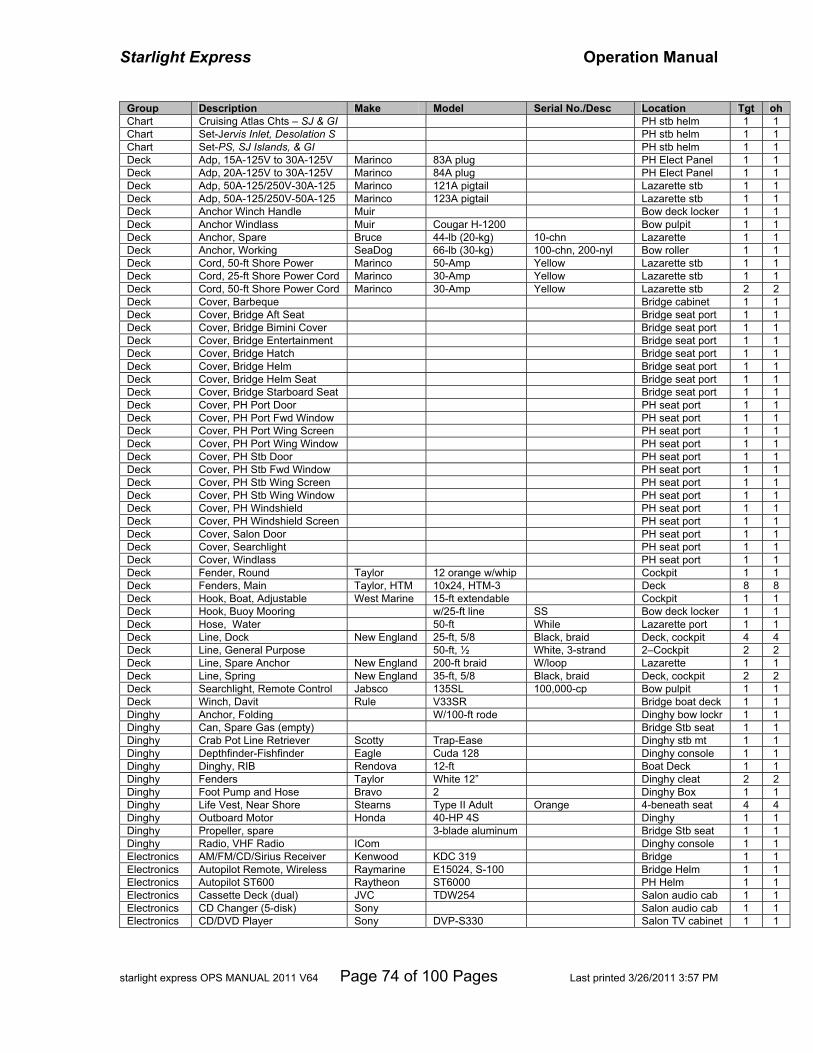
Starlight Express Operation Manual
starlight express OPS MANUAL 2011 V64 Page 74 of 100 Pages Last printed 3/26/2011 3:57 PM
Group Description Make Model Serial No./Desc Location Tgt oh Chart Cruising Atlas Chts – SJ & GI PH stb helm 1 1 Chart Set-Jervis Inlet, Desolation S PH stb helm 1 1 Chart Set-PS, SJ Islands, & GI PH stb helm 1 1 Deck Adp, 15A-125V to 30A-125V Marinco 83A plug PH Elect Panel 1 1 Deck Adp, 20A-125V to 30A-125V Marinco 84A plug PH Elect Panel 1 1 Deck Adp, 50A-125/250V-30A-125 Marinco 121A pigtail Lazarette stb 1 1 Deck Adp, 50A-125/250V-50A-125 Marinco 123A pigtail Lazarette stb 1 1 Deck Anchor Winch Handle Muir Bow deck locker 1 1 Deck Anchor Windlass Muir Cougar H-1200 Bow pulpit 1 1 Deck Anchor, Spare Bruce 44-lb (20-kg) 10-chn Lazarette 1 1 Deck Anchor, Working SeaDog 66-lb (30-kg) 100-chn, 200-nyl Bow roller 1 1 Deck Cord, 50-ft Shore Power Marinco 50-Amp Yellow Lazarette stb 1 1 Deck Cord, 25-ft Shore Power Cord Marinco 30-Amp Yellow Lazarette stb 1 1 Deck Cord, 50-ft Shore Power Cord Marinco 30-Amp Yellow Lazarette stb 2 2 Deck Cover, Barbeque Bridge cabinet 1 1 Deck Cover, Bridge Aft Seat Bridge seat port 1 1 Deck Cover, Bridge Bimini Cover Bridge seat port 1 1 Deck Cover, Bridge Entertainment Bridge seat port 1 1 Deck Cover, Bridge Hatch Bridge seat port 1 1 Deck Cover, Bridge Helm Bridge seat port 1 1 Deck Cover, Bridge Helm Seat Bridge seat port 1 1 Deck Cover, Bridge Starboard Seat Bridge seat port 1 1 Deck Cover, PH Port Door PH seat port 1 1 Deck Cover, PH Port Fwd Window PH seat port 1 1 Deck Cover, PH Port Wing Screen PH seat port 1 1 Deck Cover, PH Port Wing Window PH seat port 1 1 Deck Cover, PH Stb Door PH seat port 1 1 Deck Cover, PH Stb Fwd Window PH seat port 1 1 Deck Cover, PH Stb Wing Screen PH seat port 1 1 Deck Cover, PH Stb Wing Window PH seat port 1 1 Deck Cover, PH Windshield PH seat port 1 1 Deck Cover, PH Windshield Screen PH seat port 1 1 Deck Cover, Salon Door PH seat port 1 1 Deck Cover, Searchlight PH seat port 1 1 Deck Cover, Windlass PH seat port 1 1 Deck Fender, Round Taylor 12 orange w/whip Cockpit 1 1 Deck Fenders, Main Taylor, HTM 10x24, HTM-3 Deck 8 8 Deck Hook, Boat, Adjustable West Marine 15-ft extendable Cockpit 1 1 Deck Hook, Buoy Mooring w/25-ft line SS Bow deck locker 1 1 Deck Hose, Water 50-ft While Lazarette port 1 1 Deck Line, Dock New England 25-ft, 5/8 Black, braid Deck, cockpit 4 4 Deck Line, General Purpose 50-ft, ½ White, 3-strand 2–Cockpit 2 2 Deck Line, Spare Anchor New England 200-ft braid W/loop Lazarette 1 1 Deck Line, Spring New England 35-ft, 5/8 Black, braid Deck, cockpit 2 2 Deck Searchlight, Remote Control Jabsco 135SL 100,000-cp Bow pulpit 1 1 Deck Winch, Davit Rule V33SR Bridge boat deck 1 1 Dinghy Anchor, Folding W/100-ft rode Dinghy bow lockr 1 1 Dinghy Can, Spare Gas (empty) Bridge Stb seat 1 1 Dinghy Crab Pot Line Retriever Scotty Trap-Ease Dinghy stb mt 1 1 Dinghy Depthfinder-Fishfinder Eagle Cuda 128 Dinghy console 1 1 Dinghy Dinghy, RIB Rendova 12-ft Boat Deck 1 1 Dinghy Fenders Taylor White 12” Dinghy cleat 2 2 Dinghy Foot Pump and Hose Bravo 2 Dinghy Box 1 1 Dinghy Life Vest, Near Shore Stearns Type II Adult Orange 4-beneath seat 4 4 Dinghy Outboard Motor Honda 40-HP 4S Dinghy 1 1 Dinghy Propeller, spare 3-blade aluminum Bridge Stb seat 1 1 Dinghy Radio, VHF Radio ICom Dinghy console 1 1 Electronics AM/FM/CD/Sirius Receiver Kenwood KDC 319 Bridge 1 1 Electronics Autopilot Remote, Wireless Raymarine E15024, S-100 Bridge Helm 1 1 Electronics Autopilot ST600 Raytheon ST6000 PH Helm 1 1 Electronics Cassette Deck (dual) JVC TDW254 Salon audio cab 1 1 Electronics CD Changer (5-disk) Sony Salon audio cab 1 1 Electronics CD/DVD Player Sony DVP-S330 Salon TV cabinet 1 1
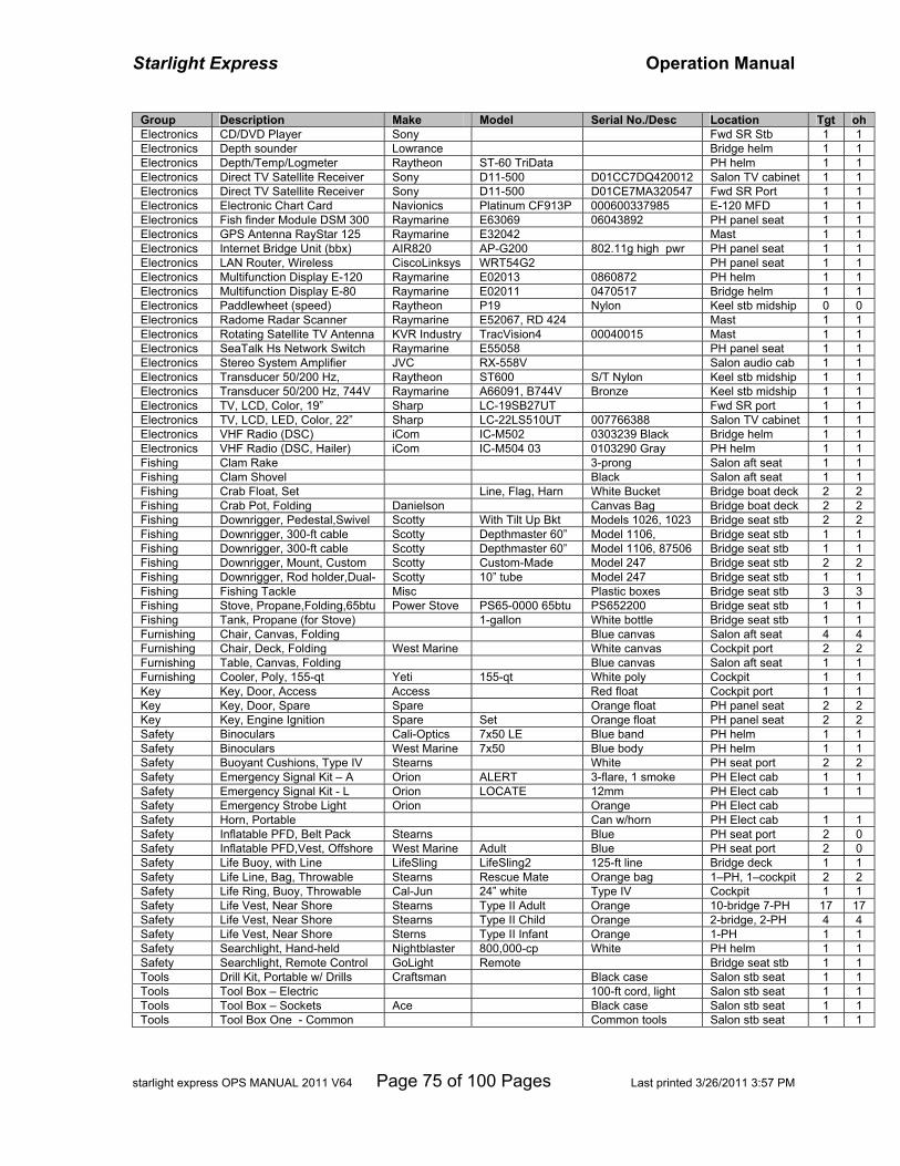
Starlight Express Operation Manual
starlight express OPS MANUAL 2011 V64 Page 75 of 100 Pages Last printed 3/26/2011 3:57 PM
Group Description Make Model Serial No./Desc Location Tgt oh Electronics CD/DVD Player Sony Fwd SR Stb 1 1 Electronics Depth sounder Lowrance Bridge helm 1 1 Electronics Depth/Temp/Logmeter Raytheon ST-60 TriData PH helm 1 1 Electronics Direct TV Satellite Receiver Sony D11-500 D01CC7DQ420012 Salon TV cabinet 1 1 Electronics Direct TV Satellite Receiver Sony D11-500 D01CE7MA320547 Fwd SR Port 1 1 Electronics Electronic Chart Card Navionics Platinum CF913P 000600337985 E-120 MFD 1 1 Electronics Fish finder Module DSM 300 Raymarine E63069 06043892 PH panel seat 1 1 Electronics GPS Antenna RayStar 125 Raymarine E32042 Mast 1 1 Electronics Internet Bridge Unit (bbx) AIR820 AP-G200 802.11g high pwr PH panel seat 1 1 Electronics LAN Router, Wireless CiscoLinksys WRT54G2 PH panel seat 1 1 Electronics Multifunction Display E-120 Raymarine E02013 0860872 PH helm 1 1 Electronics Multifunction Display E-80 Raymarine E02011 0470517 Bridge helm 1 1 Electronics Paddlewheet (speed) Raytheon P19 Nylon Keel stb midship 0 0 Electronics Radome Radar Scanner Raymarine E52067, RD 424 Mast 1 1 Electronics Rotating Satellite TV Antenna KVR Industry TracVision4 00040015 Mast 1 1 Electronics SeaTalk Hs Network Switch Raymarine E55058 PH panel seat 1 1 Electronics Stereo System Amplifier JVC RX-558V Salon audio cab 1 1 Electronics Transducer 50/200 Hz, Raytheon ST600 S/T Nylon Keel stb midship 1 1 Electronics Transducer 50/200 Hz, 744V Raymarine A66091, B744V Bronze Keel stb midship 1 1 Electronics TV, LCD, Color, 19” Sharp LC-19SB27UT Fwd SR port 1 1 Electronics TV, LCD, LED, Color, 22” Sharp LC-22LS510UT 007766388 Salon TV cabinet 1 1 Electronics VHF Radio (DSC) iCom IC-M502 0303239 Black Bridge helm 1 1 Electronics VHF Radio (DSC, Hailer) iCom IC-M504 03 0103290 Gray PH helm 1 1 Fishing Clam Rake 3-prong Salon aft seat 1 1 Fishing Clam Shovel Black Salon aft seat 1 1 Fishing Crab Float, Set Line, Flag, Harn White Bucket Bridge boat deck 2 2 Fishing Crab Pot, Folding Danielson Canvas Bag Bridge boat deck 2 2 Fishing Downrigger, Pedestal,Swivel Scotty With Tilt Up Bkt Models 1026, 1023 Bridge seat stb 2 2 Fishing Downrigger, 300-ft cable Scotty Depthmaster 60” Model 1106, Bridge seat stb 1 1 Fishing Downrigger, 300-ft cable Scotty Depthmaster 60” Model 1106, 87506 Bridge seat stb 1 1 Fishing Downrigger, Mount, Custom Scotty Custom-Made Model 247 Bridge seat stb 2 2 Fishing Downrigger, Rod holder,Dual- Scotty 10” tube Model 247 Bridge seat stb 1 1 Fishing Fishing Tackle Misc Plastic boxes Bridge seat stb 3 3 Fishing Stove, Propane,Folding,65btu Power Stove PS65-0000 65btu PS652200 Bridge seat stb 1 1 Fishing Tank, Propane (for Stove) 1-gallon White bottle Bridge seat stb 1 1 Furnishing Chair, Canvas, Folding Blue canvas Salon aft seat 4 4 Furnishing Chair, Deck, Folding West Marine White canvas Cockpit port 2 2 Furnishing Table, Canvas, Folding Blue canvas Salon aft seat 1 1 Furnishing Cooler, Poly, 155-qt Yeti 155-qt White poly Cockpit 1 1 Key Key, Door, Access Access Red float Cockpit port 1 1 Key Key, Door, Spare Spare Orange float PH panel seat 2 2 Key Key, Engine Ignition Spare Set Orange float PH panel seat 2 2 Safety Binoculars Cali-Optics 7x50 LE Blue band PH helm 1 1 Safety Binoculars West Marine 7x50 Blue body PH helm 1 1 Safety Buoyant Cushions, Type IV Stearns White PH seat port 2 2 Safety Emergency Signal Kit – A Orion ALERT 3-flare, 1 smoke PH Elect cab 1 1 Safety Emergency Signal Kit - L Orion LOCATE 12mm PH Elect cab 1 1 Safety Emergency Strobe Light Orion Orange PH Elect cab Safety Horn, Portable Can w/horn PH Elect cab 1 1 Safety Inflatable PFD, Belt Pack Stearns Blue PH seat port 2 0 Safety Inflatable PFD,Vest, Offshore West Marine Adult Blue PH seat port 2 0 Safety Life Buoy, with Line LifeSling LifeSling2 125-ft line Bridge deck 1 1 Safety Life Line, Bag, Throwable Stearns Rescue Mate Orange bag 1–PH, 1–cockpit 2 2 Safety Life Ring, Buoy, Throwable Cal-Jun 24” white Type IV Cockpit 1 1 Safety Life Vest, Near Shore Stearns Type II Adult Orange 10-bridge 7-PH 17 17 Safety Life Vest, Near Shore Stearns Type II Child Orange 2-bridge, 2-PH 4 4 Safety Life Vest, Near Shore Sterns Type II Infant Orange 1-PH 1 1 Safety Searchlight, Hand-held Nightblaster 800,000-cp White PH helm 1 1 Safety Searchlight, Remote Control GoLight Remote Bridge seat stb 1 1 Tools Drill Kit, Portable w/ Drills Craftsman Black case Salon stb seat 1 1 Tools Tool Box – Electric 100-ft cord, light Salon stb seat 1 1 Tools Tool Box – Sockets Ace Black case Salon stb seat 1 1 Tools Tool Box One - Common Common tools Salon stb seat 1 1

Starlight Express Operation Manual
starlight express OPS MANUAL 2011 V64 Page 76 of 100 Pages Last printed 3/26/2011 3:57 PM
Group Description Make Model Serial No./Desc Location Tgt oh Tools Tool Box Two – Repair Lg Repair tools Salon stb seat 1 1
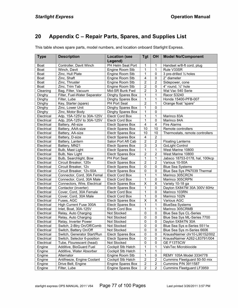
Starlight Express Operation Manual
starlight express OPS MANUAL 2011 V64 Page 77 of 100 Pages Last printed 3/26/2011 3:57 PM
20 Appendix C – Repair Parts, Spares, and Supplies List This table shows spare parts, model numbers, and location onboard Starlight Express. Type Description Location (see
Legend) Tgt OH Model No/Component
Boat Controller, Davit Winch PH Helm Seat Port 1 1 Handset w/8-ft cord, plug Boat Winch, Davit Engine Room Stb 1 1 Rule V33SR Boat Zinc, Hull Plate Engine Room Stb 1 0 3 pre-drilled ½ holes Boat Zinc, Shaft Engine Room Stb 4 0 2” diameter Boat Zinc, Thruster Engine Room Stb 2 2 Sidepower, cone Boat Zinc, Trim Tab Engine Room Stb 2 0 4” round, ½” hole Cleaning Bag, Filter, Vacuum Mid-SR Bunk Fwd 2 3 Wal Vac 540 Serie Dinghy Filter, Fuel-Water Separator Dinghy Spares Box 1 1 Racor S3240 Dinghy Filter, Lube Dinghy Spares Box 1 1 Honda 15400-PFB-007 Dinghy Key, Starter (spare) PH Port Seat 2 1 Orange float “spare” Dinghy Zinc, Lower Unit Dinghy Spares Box 1 0 Dinghy Zinc, Motor Body Dinghy Spares Box 1 0 Electrical Adp, 15A-125V to 30A-125V Electr Cord Box 1 1 Marinco 83A Electrical Adp, 20A-125V to 30A-125V Electr Cord Box 1 0 Marinco 84A Electrical Battery, A6-size Electr Spares Box 4 4 Fire Alarms Electrical Battery, AAA-size Electr Spares Box 10 10 Remote controllers Electrical Battery, AA-size Electr Spares Box 10 10 Thermostats, remote controllers Electrical Battery, D-size Electr Spares Box 4 2 Electrical Battery, Lantern Salon Port Aft Cab 2 2 Floating Lanterns Electrical Battery, MN21 Electr Spares Box 3 3 GoLight Control Electrical Bulb, Mast Light Electr Spares Box 1 1 West Marine 10800 Electrical Bulb, Nav Light Electr Spares Box 2 2 West Marine 10800 Electrical Bulb, Searchlight, Bow PH Port Seat 1 1 Jabsco 18753-0178, hal, 100kcp Electrical Circuit Breaker, 120v Electr Spares Box 2 2 Various 10-50A Electrical Circuit Breaker, 12v Electr Spares Box 0 0 Blue Sea Systems Electrical Circuit Breaker, 12v-50A Electr Spares Box 0 0 Blue Sea Sys PN7039 Thermal Electrical Connector, Cord, 30A Femal Electr Cord Box 1 1 Marinco 305CRCN Electrical Connector, Cord, 30A Male Electr Cord Box 1 0 Marinco 305CRPN Electrical Connectors, Wire, Electrical Electr Spares Box X X Variety 10-18 ga Electrical Contactor (inverter) Electr Spares Box 1 0 Dayton 5X847M 30A 300V 60Hz Electrical Cover, Cord, 30A Female Electr Cord Box 1 0 Marinco 103RN Electrical Cover, Cord, 30A Male Electr Cord Box 1 0 Marinco 102N Electrical Fuses, AGC Electr Spares Box X X Various AGC Electrical High Current Fuse 300A Electr Spares Box 1 1 BlueSea Systems Electrical Inlet, Boat, 30A-125V Electr Cord Box 1 1 Marinco 305CRMB Electrical Relay, Auto Charging Not Stocked 0 0 Blue Sea Sys CL-Series Electrical Relay, Auto Charging Not Stocked 0 0 Blue Sea Sys ML-Series 7700 Electrical Relay, Inverter Power Not Stocked 0 0 Dayton 5X847N 30A Electrical Switch, 2-Btry On/Off/Comb Not Stocked 0 0 Blue Sea Sys e-Series 5511e Electrical Switch, Battery On/Off Not Stocked 0 0 Blue Sea Sys m-Series 6606 Electrical Switch, Generator Start/Run Electr Spares Box 0 0 KraussNaimer chr10-L90152/002 Electrical Switch, Selector 6-position Electr Spares Box 0 0 KraussNaimer A262-L83791/004 Electrical Tube, Flourescent (head) Not Stocked 0 0 GE F13T5CW Engine Additive, BioGuard Fuel Cockpit Stb Hatch 1 1 ValvTec Microbiocide Engine Additive, Water Absorber Cockpit Stb Hatch 1 1 Engine Alternator Engine Room Stb 1 0 REMY 105A Model 3334778 Engine Antifreeze, Engine Coolant Cockpit Stb Hatch 2 2 Cummins Fleetguard 50-50 mix Engine Drive Belt, Engine Engine Spares Box 2 2 Cummins P/N 3911587 Engine Filter, Lube Engine Spares Box 2 2 Cummins Fleetguard LF3959
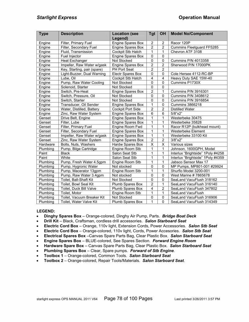
Starlight Express Operation Manual
starlight express OPS MANUAL 2011 V64 Page 78 of 100 Pages Last printed 3/26/2011 3:57 PM
Type Description Location (see Legend)
Tgt OH Model No/Component
Engine Filter, Primary Fuel Engine Spares Box 2 2 Racor 120P Engine Filter, Secondary Fuel Engine Spares Box 2 2 Cummins Fleetguard FF5285 Engine Fluid, Transmission Cockpit Stb Hatch 1 1 Chevron ATF 3108 Engine Fuel Injector Engine Spares Box 0 0 Engine Heat Exchanger Not Stocked 0 0 Cummins P/N 4013358 Engine Impeller, Raw Water w/gask Engine Spares Box 2 2 Sherwood P/N 17000PK Engine Key, Starting, pair (spare) PH Port Seat 2 2 Engine Light-Buzzer, Dual Warning Electr Spares Box 0 0 Cole Hersee 4112-RC-BP Engine Lube, Oil Cockpit Stb Hatch 4 4 Heavy Duty SAE 15W-40 Engine Pump, Raw Water Cooling Not Stocked 0 0 Cummins P1730X Engine Solenoid, Starter Not Stocked 0 0 Engine Switch, Pre-Heat Engine Spares Box 2 1 Cummins P/N 3916301 Engine Switch, Pressure, Oil Not Stocked 0 0 Cummins P/N 3408612 Engine Switch, Starter Not Stocked 0 0 Cummins P/N 3916854 Engine Transducer, Oil Sender Engine Spares Box 1 0 Cummins 3866218 Engine Water, Distilled, Battery Cockpit Port Side 2 2 Distilled Water Engine Zinc, Raw Water System Engine Spares Box 6 6 5/8”x2” Genset Drive Belt, Engine Engine Spares Box 1 1 Westerbeke 30475 Genset Filter, Lube Engine Spares Box 1 1 Westerbeke 35828 Genset Filter, Primary Fuel Engine Room Fwd 1 1 Racor R12P (bulkhead mount) Genset Filter, Secondary Fuel Engine Spares Box 1 1 Westerbeke Element Genset Impeller, Raw Water w/gask Engine Spares Box 1 1 Westerbeke 33100 Kit Genset Zinc, Raw Water System Engine Spares Box 2 2 3/8”x2” Hardware Bolts, Nuts, Washers Hardw Spares Box X X Various sizes Plumbing Pump, Bilge Cartridge Engine Room Stb 1 1 Johnson, 1600GPH, Model Paint Black Salon Seat Stb 1 1 Interlux “Brightside” 1Poly #4258 Paint White Salon Seat Stb 1 1 Interlux “Brightside” 1Poly #4359 Plumbing Pump, Fresh Water 4.5gpm Engine Room Stb 1 1 Jabsco Sensor Max 17 Plumbing Pump, Hygronic Water Not stocked 0 0 MP Pumps, MP801-001 #29924 Plumbing Pump, Macerator 13gpm Engine Room Stb 1 1 Shurflo Model 3200-001 Plumbing Pump, Raw Water 3.4gpm Not stocked 0 0 West Marine # 7865678 Plumbing Toilet, Ball-Shaft Kit Not Stocked 0 0 SeaLand VacuFlush 318162 Plumbing Toilet, Bowl Seal Kit Plumb Spares Box 2 1 SeaLand VacuFlush 316140 Plumbing Toilet, Duck Bill Valve Plumb Spares Box 4 2 SeaLand VacuFlush 347802 Plumbing Toilet, Motor Engine Room Stb 1 1 SeaLand VacuFlush Plumbing Toilet, Vacuum Breaker Kit Not Stocked 0 0 SeaLand VacuFlush 316906 Plumbing Toilet, Water Valve Kit Plumb Spares Box 1 0 SeaLand VacuFlush 314349
LEGEND: • Dinghy Spares Box – Orange-colored, Dinghy Air Pump, Parts. Bridge Boat Deck • Drill Kit – Black, Craftsman, cordless drill accessories. Salon Starboard Seat • Electric Cord Box – Orange, 110v light, Extension Cords, Power Accessories. Salon Stb Seat • Electric Cord Box – Orange-colored, 110v light, Cords, Power Accesories. Salon Stb Seat • Electrical Spares Box –Canvas Spare Parts Bag, Clear Plastic Box. Salon Starboard Seat • Engine Spares Box – BLUE-colored, See Spares Section. Forward Engine Room • Hardware Spare Box – Canvas Spare Parts Bag, Clear Plastic Box. Salon Starboard Seat • Plumbing Spares Box – Clear, Spare pumps. Forward of Stb Engine. • Toolbox 1 – Orange-colored, Common Tools. Salon Starboard Seat • Toolbox 2 – Orange-colored, Repair Tools/Materials. Salon Starboard Seat.
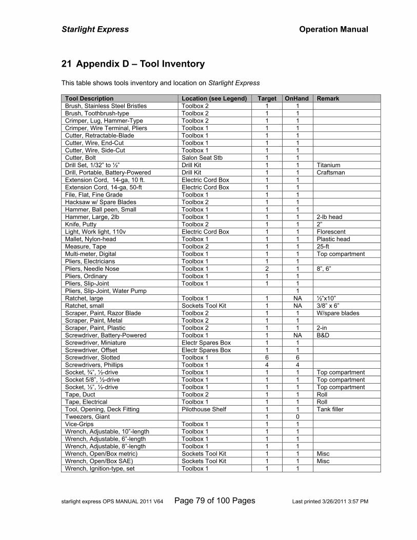
Starlight Express Operation Manual
starlight express OPS MANUAL 2011 V64 Page 79 of 100 Pages Last printed 3/26/2011 3:57 PM
21 Appendix D – Tool Inventory This table shows tools inventory and location on Starlight Express
Tool Description Location (see Legend) Target OnHand Remark Brush, Stainless Steel Bristles Toolbox 2 1 1 Brush, Toothbrush-type Toolbox 2 1 1 Crimper, Lug, Hammer-Type Toolbox 2 1 1 Crimper, Wire Terminal, Pliers Toolbox 1 1 1 Cutter, Retractable-Blade Toolbox 1 1 1 Cutter, Wire, End-Cut Toolbox 1 1 1 Cutter, Wire, Side-Cut Toolbox 1 1 1 Cutter, Bolt Salon Seat Stb 1 1 Drill Set, 1/32” to ½” Drill Kit 1 1 Titanium Drill, Portable, Battery-Powered Drill Kit 1 1 Craftsman Extension Cord, 14-ga, 10 ft. Electric Cord Box 1 1 Extension Cord, 14-ga, 50-ft Electric Cord Box 1 1 File, Flat, Fine Grade Toolbox 1 1 1 Hacksaw w/ Spare Blades Toolbox 2 1 1 Hammer, Ball peen, Small Toolbox 1 1 1 Hammer, Large, 2lb Toolbox 1 1 1 2-lb head Knife, Putty Toolbox 2 1 1 2” Light, Work light, 110v Electric Cord Box 1 1 Florescent Mallet, Nylon-head Toolbox 1 1 1 Plastic head Measure, Tape Toolbox 2 1 1 25-ft Multi-meter, Digital Toolbox 1 1 1 Top compartment Pliers, Electricians Toolbox 1 1 1 Pliers, Needle Nose Toolbox 1 2 1 8”, 6” Pliers, Ordinary Toolbox 1 1 1 Pliers, Slip-Joint Toolbox 1 1 1 Pliers, Slip-Joint, Water Pump 1 Ratchet, large Toolbox 1 1 NA ½”x10” Ratchet, small Sockets Tool Kit 1 NA 3/8” x 6” Scraper, Paint, Razor Blade Toolbox 2 1 1 W/spare blades Scraper, Paint, Metal Toolbox 2 1 1 Scraper, Paint, Plastic Toolbox 2 1 1 2-in Screwdriver, Battery-Powered Toolbox 1 1 NA B&D Screwdriver, Miniature Electr Spares Box 1 1 Screwdriver, Offset Electr Spares Box 1 1 Screwdriver, Slotted Toolbox 1 6 6 Screwdrivers, Phillips Toolbox 1 4 4 Socket, ¾”, ½-drive Toolbox 1 1 1 Top compartment Socket 5/8”, ½-drive Toolbox 1 1 1 Top compartment Socket, ½”, ½-drive Toolbox 1 1 1 Top compartment Tape, Duct Toolbox 2 1 1 Roll Tape, Electrical Toolbox 1 1 1 Roll Tool, Opening, Deck Fitting Pilothouse Shelf 1 1 Tank filler Tweezers, Giant 1 0 Vice-Grips Toolbox 1 1 1 Wrench, Adjustable, 10”-length Toolbox 1 1 1 Wrench, Adjustable, 6”-length Toolbox 1 1 1 Wrench, Adjustable, 8”-length Toolbox 1 1 1 Wrench, Open/Box metric) Sockets Tool Kit 1 1 Misc Wrench, Open/Box SAE) Sockets Tool Kit 1 1 Misc Wrench, Ignition-type, set Toolbox 1 1 1
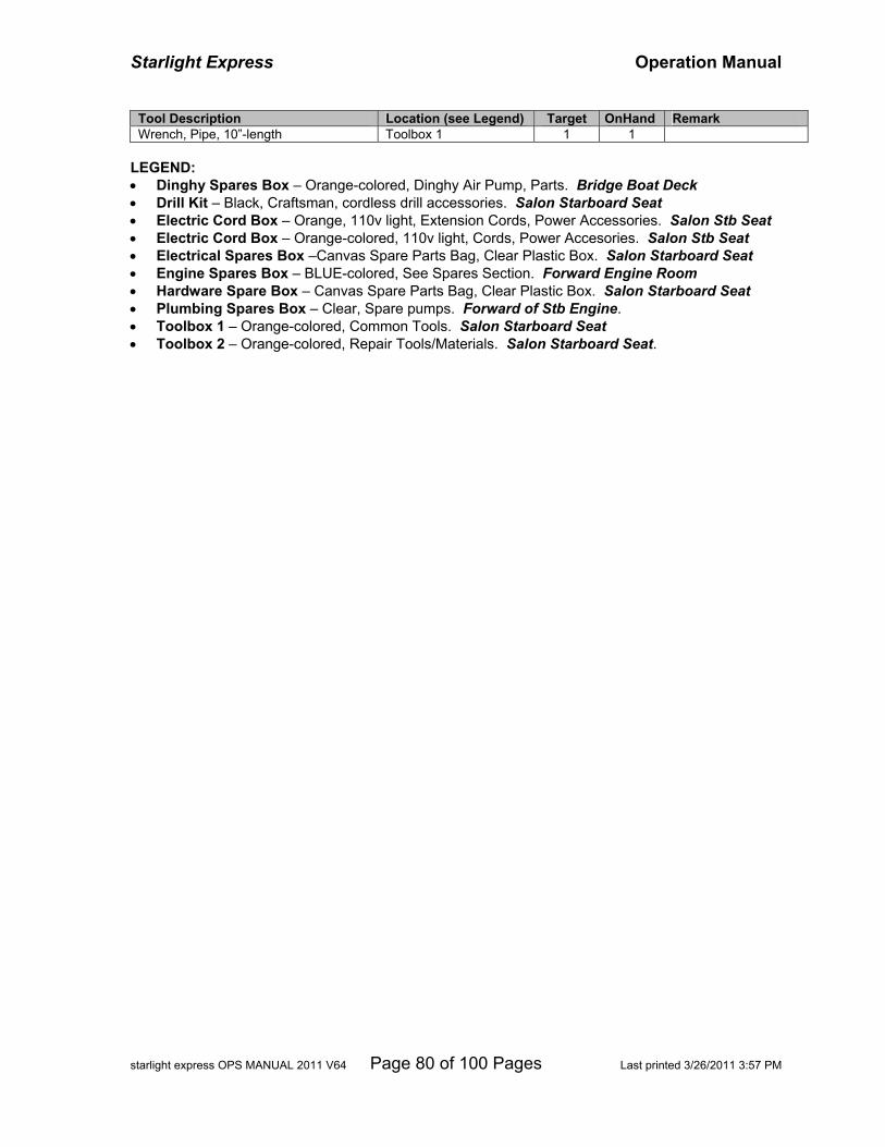
Starlight Express Operation Manual
starlight express OPS MANUAL 2011 V64 Page 80 of 100 Pages Last printed 3/26/2011 3:57 PM
Tool Description Location (see Legend) Target OnHand Remark Wrench, Pipe, 10”-length Toolbox 1 1 1
LEGEND: • Dinghy Spares Box – Orange-colored, Dinghy Air Pump, Parts. Bridge Boat Deck • Drill Kit – Black, Craftsman, cordless drill accessories. Salon Starboard Seat • Electric Cord Box – Orange, 110v light, Extension Cords, Power Accessories. Salon Stb Seat • Electric Cord Box – Orange-colored, 110v light, Cords, Power Accesories. Salon Stb Seat • Electrical Spares Box –Canvas Spare Parts Bag, Clear Plastic Box. Salon Starboard Seat • Engine Spares Box – BLUE-colored, See Spares Section. Forward Engine Room • Hardware Spare Box – Canvas Spare Parts Bag, Clear Plastic Box. Salon Starboard Seat • Plumbing Spares Box – Clear, Spare pumps. Forward of Stb Engine. • Toolbox 1 – Orange-colored, Common Tools. Salon Starboard Seat • Toolbox 2 – Orange-colored, Repair Tools/Materials. Salon Starboard Seat.
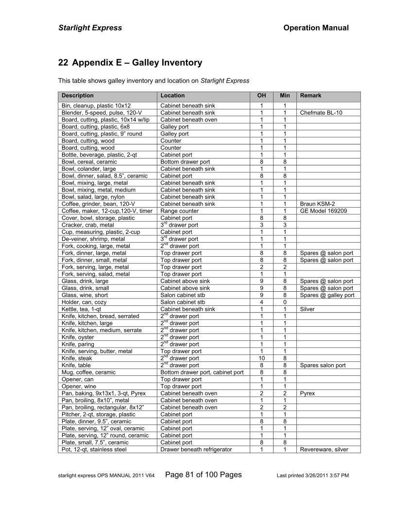
Starlight Express Operation Manual
starlight express OPS MANUAL 2011 V64 Page 81 of 100 Pages Last printed 3/26/2011 3:57 PM
22 Appendix E – Galley Inventory This table shows galley inventory and location on Starlight Express
Description Location OH Min Remark
Bin, cleanup, plastic 10x12 Cabinet beneath sink 1 1 Blender, 5-speed, pulse, 120-V Cabinet beneath sink 1 1 Chefmate BL-10 Board, cutting, plastic, 10x14 w/lip Cabinet beneath oven 1 1 Board, cutting, plastic, 6x8 Galley port 1 1 Board, cutting, plastic, 9” round Galley port 1 1 Board, cutting, wood Counter 1 1 Board, cutting, wood Counter 1 1 Bottle, beverage, plastic, 2-qt Cabinet port 1 1 Bowl, cereal, ceramic Bottom drawer port 8 8 Bowl, colander, large Cabinet beneath sink 1 1 Bowl, dinner, salad, 8.5”, ceramic Cabinet port 8 8 Bowl, mixing, large, metal Cabinet beneath sink 1 1 Bowl, mixing, metal, medium Cabinet beneath sink 1 1 Bowl, salad, large, nylon Cabinet beneath sink 1 1 Coffee, grinder, bean, 120-V Cabinet beneath sink 1 1 Braun KSM-2 Coffee, maker, 12-cup,120-V, timer Range counter 1 1 GE Model 169209 Cover, bowl, storage, plastic Cabinet port 8 8 Cracker, crab, metal 3rd drawer port 3 3 Cup, measuring, plastic, 2-cup Cabinet port 1 1 De-veiner, shrimp, metal 3rd drawer port 1 1 Fork, cooking, large, metal 2nd drawer port 1 1 Fork, dinner, large, metal Top drawer port 8 8 Spares @ salon port Fork, dinner, small, metal Top drawer port 8 8 Spares @ salon port Fork, serving, large, metal Top drawer port 2 2 Fork, serving, salad, metal Top drawer port 1 1 Glass, drink, large Cabinet above sink 9 8 Spares @ salon port Glass, drink, small Cabinet above sink 9 8 Spares @ salon port Glass, wine, short Salon cabinet stb 9 8 Spares @ galley port Holder, can, cozy Salon cabinet stb 4 0 Kettle, tea, 1-qt Cabinet beneath sink 1 1 Silver Knife, kitchen, bread, serrated 2nd drawer port 1 1 Knife, kitchen, large 2nd drawer port 1 1 Knife, kitchen, medium, serrate 2nd drawer port 1 1 Knife, oyster 2nd drawer port 1 1 Knife, paring 2nd drawer port 1 1 Knife, serving, butter, metal Top drawer port 1 1 Knife, steak 2nd drawer port 10 8 Knife, table 2nd drawer port 8 8 Spares salon port Mug, coffee, ceramic Bottom drawer port, cabinet port 8 8 Opener, can Top drawer port 1 1 Opener, wine Top drawer port 1 1 Pan, baking, 9x13x1, 3-qt, Pyrex Cabinet beneath oven 2 2 Pyrex Pan, broiling, 8x10”, metal Cabinet beneath oven 1 1 Pan, broiling, rectangular, 8x12” Cabinet beneath oven 2 2 Pitcher, 2-qt, storage, plastic Cabinet port 1 1 Plate, dinner, 9.5”, ceramic Cabinet port 8 8 Plate, serving, 12” oval, ceramic Cabinet port 1 1 Plate, serving, 12” round, ceramic Cabinet port 1 1 Plate, small, 7.5”, ceramic Cabinet port 8 8 Pot, 12-qt, stainless steel Drawer beneath refrigerator 1 1 Revereware, silver
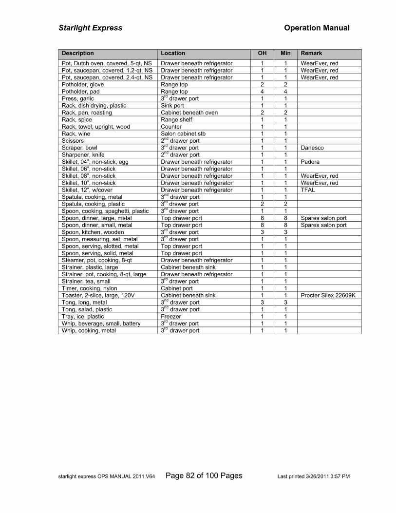
Starlight Express Operation Manual
starlight express OPS MANUAL 2011 V64 Page 82 of 100 Pages Last printed 3/26/2011 3:57 PM
Description Location OH Min Remark
Pot, Dutch oven, covered, 5-qt, NS Drawer beneath refrigerator 1 1 WearEver, red Pot, saucepan, covered, 1.2-qt, NS Drawer beneath refrigerator 1 1 WearEver, red Pot, saucepan, covered, 2.4-qt, NS Drawer beneath refrigerator 1 1 WearEver, red Potholder, glove Range top 2 2 Potholder, pad Range top 4 4 Press, garlic 3rd drawer port 1 1 Rack, dish drying, plastic Sink port 1 1 Rack, pan, roasting Cabinet beneath oven 2 2 Rack, spice Range shelf 1 1 Rack, towel, upright, wood Counter 1 1 Rack, wine Salon cabinet stb 1 1 Scissors 2nd drawer port 1 1 Scraper, bowl 3rd drawer port 1 1 Danesco Sharpener, knife 2nd drawer port 1 1 Skillet, 04”, non-stick, egg Drawer beneath refrigerator 1 1 Padera Skillet, 06”, non-stick Drawer beneath refrigerator 1 1 Skillet, 08”, non-stick Drawer beneath refrigerator 1 1 WearEver, red Skillet, 10”, non-stick Drawer beneath refrigerator 1 1 WearEver, red Skillet, 12”, w/cover Drawer beneath refrigerator 1 1 TFAL Spatula, cooking, metal 3nd drawer port 1 1 Spatula, cooking, plastic 3rd drawer port 2 2 Spoon, cooking, spaghetti, plastic 3rd drawer port 1 1 Spoon, dinner, large, metal Top drawer port 8 8 Spares salon port Spoon, dinner, small, metal Top drawer port 8 8 Spares salon port Spoon, kitchen, wooden 3rd drawer port 3 3 Spoon, measuring, set, metal 3rd drawer port 1 1 Spoon, serving, slotted, metal Top drawer port 1 1 Spoon, serving, solid, metal Top drawer port 1 1 Steamer, pot, cooking, 8-qt Drawer beneath refrigerator 1 1 Strainer, plastic, large Cabinet beneath sink 1 1 Strainer, pot, cooking, 8-qt, large Drawer beneath refrigerator 1 1 Strainer, tea, small 3rd drawer port 1 1 Timer, cooking, nylon Cabinet port 1 1 Toaster, 2-slice, large, 120V Cabinet beneath sink 1 1 Procter Silex 22609K Tong, long, metal 3nd drawer port 3 3 Tong, salad, plastic 3nd drawer port 1 1 Tray, ice, plastic Freezer 1 1 Whip, beverage, small, battery 3rd drawer port 1 1 Whip, cooking, metal 3rd drawer port 1 1

Starlight Express Operation Manual
starlight express OPS MANUAL 2011 V64 Page 83 of 100 Pages Last printed 3/26/2011 3:57 PM
23 Appendix F – Machinery/Electrical Data Item Description/Model Serial/ID Number Location/Notes Battery Bank #1, House (boat) 4x Trojan T105 (6-volt 2-pair) Installed 07/2009 Lazarette Port Battery Bank #2, Inverter 4x Dyno GC2B (6-volt 2-pair) Installed 12/2005 Lazarette Stb Battery Bank, Thruster 2x Optima 12-volt (Glasmat) Installed 02/2009 Fwd Stateroom Battery, Engine, Port Group 8D 12-volt Installed 12/2008 Lazarette Stb Battery, Engine, Starboard Group 8D 12-volt Installed 12/2008 Lazarette Stb Battery, Generator SeaVolt Group 24 12-volt Installed 09/2007 Lazarette Stb Battery, Dinghy SeaVolt Group 810 12-volt Installed 10/2010 Dinghy Boat, 4788, Hull Bayliner 4788ES BLBA65EVA000 Transom starboard Boat, RIB, Dinghy Rendova ROGPR12 12-ft S/N RH025050L899 1999 Charger, Battery, House Promariner Promatic 50-3 Engine Room Port Charger, Battery, Thruster Xantrex XC1524 (24-volt) Installed 02/2009 Fwd Stateroom Anchor Windlass Muir Cougar H-1200 Bow Pulpit Engine, Diesel, Port Cummins 6BTA3.9M 45923734, CPL2208 Engine, Diesel, Starboard Cummins 6BTA3.9M 45925219, CPL2208 Replaced 1044.4-hrs Engine, Oil Type Heavy Duty SAE 15W-40 Lazarette Generator, Diesel Westerbeke 12.5BTDA S/N 12 Kilowatt Inverter/Charger, 120AC/12DC Outback VXF2812M Installed 02/2006 2800 Watt, Salon Aft Motor, Outboard Honda 40HP 4S S/N Dinghy Transom Propeller 2x 4-blade pitch Pump, Raw Water, Washdown WM Washdown 3.4 #7865678 Engine Room Aft Port Pump, Water, Accumulator Shurflo 181-201 20 PSI 181-201 20-PSI Engine Room Fwd Pump, Water, Freshwater Jabsco Sensor Max 17 4.5gpm Installed 08/2010 Engine Room Fwd Receiver, TV, Satellite Sony SAT-B55 S/N 8015358 03/2009 Salon Receiver, TV, Satellite Sony SAT-B55 S/N 8013263 03/2009 Fwd Stateroom Thruster, Bow, Gear Leg SidePower SE 120/215 T-24V 706107/4607 Fwd SR, Thrust 242lbs Tracker, TV, Satellite KVH Industries TracVision S/N 00040015 01-0234-01 TV4 U.S. Transmission, Port ZF Hurth Ratio 1.95 Transmission, Starboard ZF Hurth Ratio 1.95

Starlight Express Operation Manual
starlight express OPS MANUAL 2011 V64 Page 84 of 100 Pages Last printed 3/26/2011 3:57 PM
BLANK PAGE
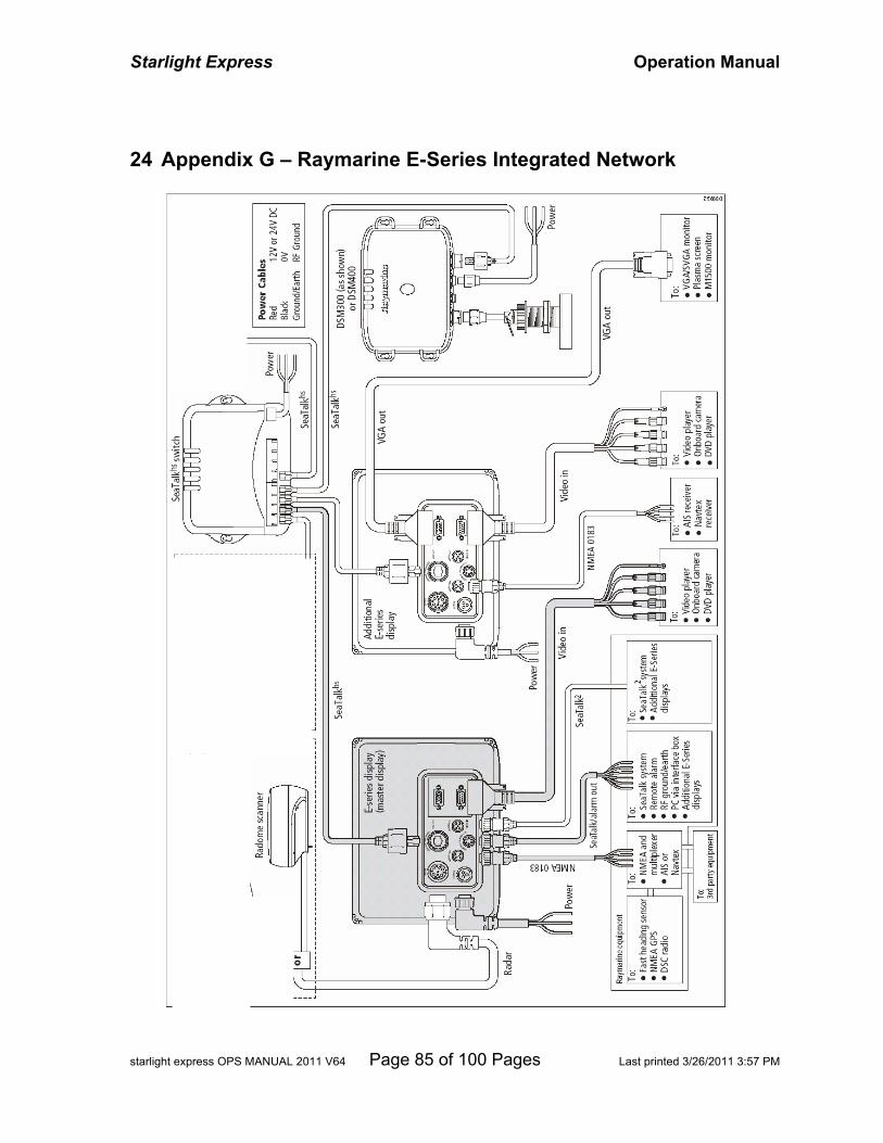
Starlight Express Operation Manual
starlight express OPS MANUAL 2011 V64 Page 85 of 100 Pages Last printed 3/26/2011 3:57 PM
24 Appendix G – Raymarine E-Series Integrated Network

Starlight Express Operation Manual
starlight express OPS MANUAL 2011 V64 Page 86 of 100 Pages Last printed 3/26/2011 3:57 PM
BLANK PAGE
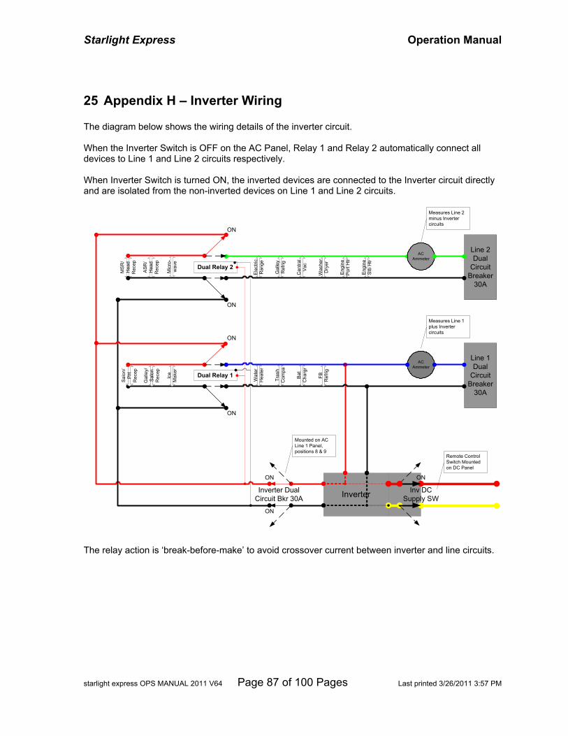
Starlight Express Operation Manual
starlight express OPS MANUAL 2011 V64 Page 87 of 100 Pages Last printed 3/26/2011 3:57 PM
25 Appendix H – Inverter Wiring The diagram below shows the wiring details of the inverter circuit. When the Inverter Switch is OFF on the AC Panel, Relay 1 and Relay 2 automatically connect all devices to Line 1 and Line 2 circuits respectively. When Inverter Switch is turned ON, the inverted devices are connected to the Inverter circuit directly and are isolated from the non-inverted devices on Line 1 and Line 2 circuits.
Inverter
Line 2Dual
CircuitBreaker
30A
Line 1Dual
CircuitBreaker
30A
Salo
n/P
HR
ecep
FBR
efrig
Gal
ley/
Salo
nR
ecep
Ice
Mak
er
Wat
erH
eate
r
Tras
hC
ompa
Bat
Cha
rgr
MSR
/H
ead
Rec
ep
ASR
/H
ead
Rec
ep
Mic
ro-
wav
e
Eng
ine
Por
t Htr
Elec
tric
Ran
ge
Gal
ley
Ref
rig
Was
her
Dry
er
Cen
tral
Vac
ACAmmeter
ACAmmeter
Eng
ine
Stb
Htr
Inverter DualCircuit Bkr 30A
Inv DCSupply SW
Dual Relay 1
Dual Relay 2
ON
ON
ON
ON
ON
ON
ON
Measures Line 1plus Invertercircuits
Measures Line 2minus Invertercircuits
Remote ControlSwitch Mountedon DC Panel
Mounted on ACLine 1 Panel,positions 8 & 9
The relay action is ‘break-before-make’ to avoid crossover current between inverter and line circuits.

Starlight Express Operation Manual
starlight express OPS MANUAL 2011 V64 Page 88 of 100 Pages Last printed 3/26/2011 3:57 PM
BLANK PAGE
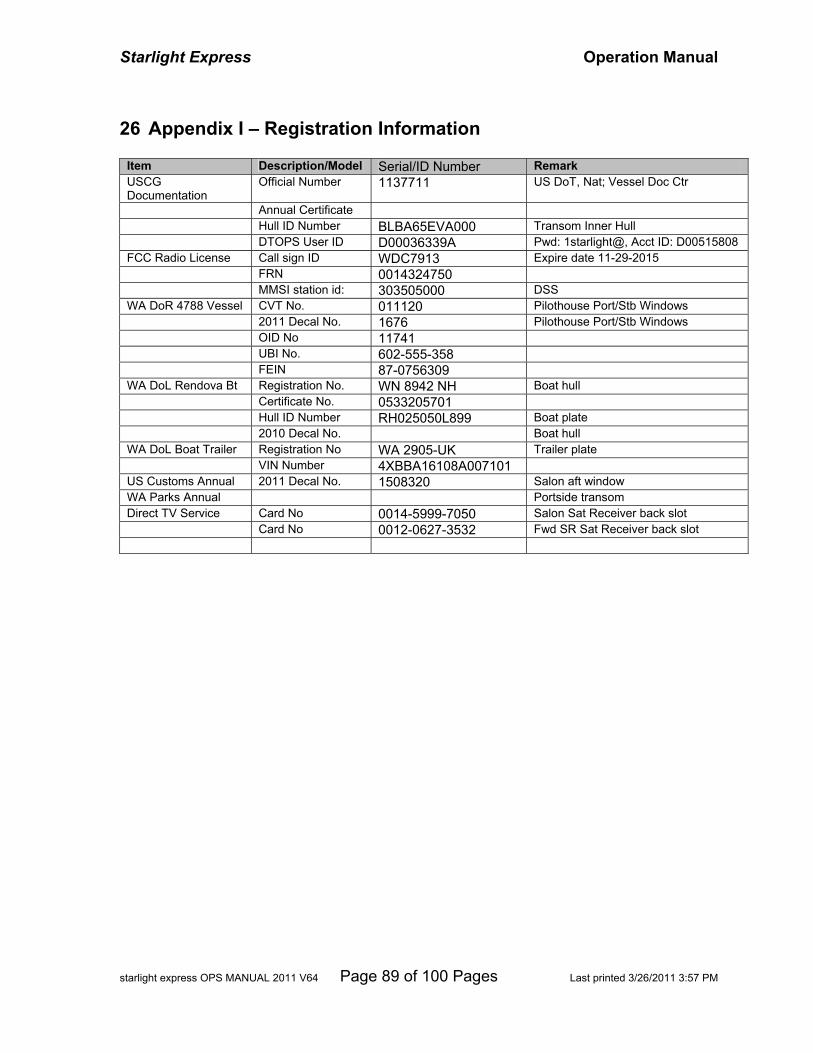
Starlight Express Operation Manual
starlight express OPS MANUAL 2011 V64 Page 89 of 100 Pages Last printed 3/26/2011 3:57 PM
26 Appendix I – Registration Information
Item Description/Model Serial/ID Number Remark USCG Documentation
Official Number 1137711 US DoT, Nat; Vessel Doc Ctr
Annual Certificate Hull ID Number BLBA65EVA000 Transom Inner Hull DTOPS User ID D00036339A Pwd: 1starlight@, Acct ID: D00515808 FCC Radio License Call sign ID WDC7913 Expire date 11-29-2015 FRN 0014324750 MMSI station id: 303505000 DSS WA DoR 4788 Vessel CVT No. 011120 Pilothouse Port/Stb Windows 2011 Decal No. 1676 Pilothouse Port/Stb Windows OID No 11741 UBI No. 602-555-358 FEIN 87-0756309 WA DoL Rendova Bt Registration No. WN 8942 NH Boat hull Certificate No. 0533205701 Hull ID Number RH025050L899 Boat plate 2010 Decal No. Boat hull WA DoL Boat Trailer Registration No WA 2905-UK Trailer plate VIN Number 4XBBA16108A007101 US Customs Annual 2011 Decal No. 1508320 Salon aft window WA Parks Annual Portside transom Direct TV Service Card No 0014-5999-7050 Salon Sat Receiver back slot Card No 0012-0627-3532 Fwd SR Sat Receiver back slot

Starlight Express Operation Manual
starlight express OPS MANUAL 2011 V64 Page 90 of 100 Pages Last printed 3/26/2011 3:57 PM
BLANK PAGE
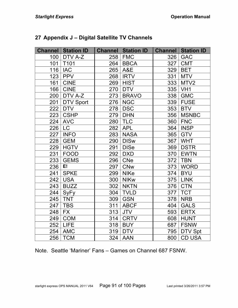
Starlight Express Operation Manual
starlight express OPS MANUAL 2011 V64 Page 91 of 100 Pages Last printed 3/26/2011 3:57 PM
27 Appendix J – Digital Satellite TV Channels Channel Station ID Channel Station ID Channel Station ID
100 DTV A-Z 258 FMC 326 GAC 101 T101 264 BBCA 327 CMT 116 IAC 265 A&E 329 BET 123 PPV 268 IRTV 331 MTV 161 CINE 269 HIST 333 MTV2 166 CINE 270 DTV 335 VH1 200 DTV A-Z 273 BRAVO 338 GMC 201 DTV Sport 276 NGC 339 FUSE 222 DTV 278 DSC 353 BTV 223 CSHP 279 DHN 356 MSNBC 224 AVC 280 TLC 360 FNC 226 LC 282 APL 364 INSP 227 INFO 283 NASA 365 GTV 228 GEM 290 DISw 367 WHT 229 HGTV 291 DISe 369 DSTR 231 FOOD 292 DXD 370 EWTN 233 GEMS 296 CNe 372 TBN 236 E! 297 CNw 373 WORD 241 SPKE 299 NIKe 374 BYU 242 USA 300 NIKw 375 LINK 243 BUZZ 302 NKTN 376 CTN 244 SyFy 304 TVLD 377 TCT 245 TNT 309 GSN 378 NRB 247 TBS 311 ABCF 404 GALS 248 FX 313 JTV 593 ERTX 249 COM 314 CRTV 608 HUNT 252 LIFE 318 BUY 687 FSNW 254 AMC 319 DTV 795 DTV Spt 256 TCM 324 AAN 800 CD USA
Note. Seattle ‘Mariner’ Fans – Games on Channel 687 FSNW.

Starlight Express Operation Manual
starlight express OPS MANUAL 2011 V64 Page 92 of 100 Pages Last printed 3/26/2011 3:57 PM
BLANK PAGE
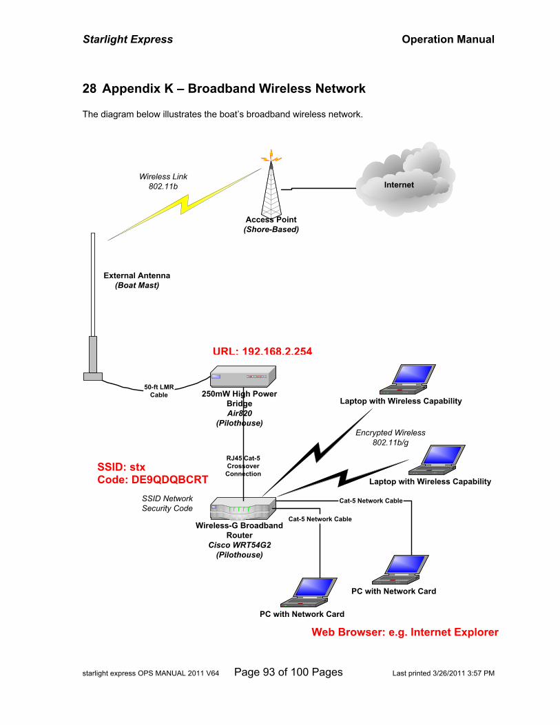
Starlight Express Operation Manual
starlight express OPS MANUAL 2011 V64 Page 93 of 100 Pages Last printed 3/26/2011 3:57 PM
28 Appendix K – Broadband Wireless Network The diagram below illustrates the boat’s broadband wireless network.
InternetInternet
Laptop with Wireless Capability
Wireless-G BroadbandRouter
Cisco WRT54G2(Pilothouse)
250mW High PowerBridgeAir820
(Pilothouse)
Access Point(Shore-Based)
50-ft LMRCable
RJ45 Cat-5CrossoverConnection
External Antenna(Boat Mast)
Laptop with Wireless Capability
PC with Network Card
Cat-5 Network Cable
PC with Network Card
Cat-5 Network Cable
Encrypted Wireless802.11b/g
Wireless Link802.11b
SSID NetworkSecurity Code
SSID: stx Code: DE9QDQBCRT
URL: 192.168.2.254
Web Browser: e.g. Internet Explorer

Starlight Express Operation Manual
starlight express OPS MANUAL 2011 V64 Page 94 of 100 Pages Last printed 3/26/2011 3:57 PM
BLANK PAGE
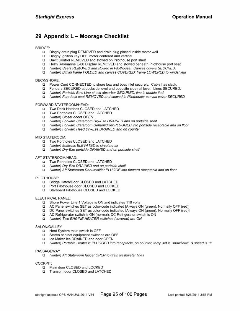
Starlight Express Operation Manual
starlight express OPS MANUAL 2011 V64 Page 95 of 100 Pages Last printed 3/26/2011 3:57 PM
29 Appendix L – Moorage Checklist BRIDGE:
Dinghy drain plug REMOVED and drain plug placed inside motor well Dinghy Ignition key OFF; motor centered and vertical Davit Control REMOVED and stowed on Pilothouse port shelf Helm Raymarine E-60 Display REMOVED and stowed beneath Pilothouse port seat (winter) Seats REMOVED and stowed in Pilothouse. Canvas covers SECURED. (winter) Bimini frame FOLDED and canvas COVERED; frame LOWERED to windshield
DECK/SHORE:
Power Cord CONNECTED to shore box and boat inlet securely. Cable has slack. Fenders SECURED at dockside level and opposite side rail level. Lines SECURED. (winter) Portside Bow Line shock absorber SECURED; line is double tied. (winter) Foredeck seat REMOVED and stowed in Pilothouse; canvas cover SECURED
FORWARD STATEROOM/HEAD:
Two Deck Hatches CLOSED and LATCHED Two Portholes CLOSED and LATCHED (winter) Closet doors OPEN (winter) Forward Stateroom Dry-Eze DRAINED and on portside shelf (winter) Forward Stateroom Dehumidifier PLUGGED into portside receptacle and on floor (winter) Forward Head Dry-Eze DRAINED and on counter
MID STATEROOM:
Two Portholes CLOSED and LATCHED (winter) Mattress ELEVATED to circulate air (winter) Dry-Eze portside DRAINED and on portside shelf
AFT STATEROOM/HEAD:
Two Portholes CLOSED and LATCHED (winter) Dry-Eze DRAINED and on portside shelf (winter) Aft Stateroom Dehumidifier PLUGGE into forward receptacle and on floor
PILOTHOUSE:
Bridge Hatch/Door CLOSED and LATCHED Port Pilothouse door CLOSED and LOCKED Starboard Pilothouse CLOSED and LOCKED
ELECTRICAL PANEL:
Shore Power Line 1 Voltage is ON and indicates 110 volts AC Panel switches SET as color-code indicated [Always ON (green), Normally OFF (red)] DC Panel switches SET as color-code indicated [Always ON (green), Normally OFF (red)] AC Refrigerator switch is ON (normal); DC Refrigerator switch is ON (winter) Two ENGINE HEATER switches (covered) are ON
SALON/GALLEY
Heat System main switch is OFF Stereo cabinet equipment switches are OFF Ice Maker Ice DRAINED and door OPEN (winter) Portable Heater is PLUGGED into receptacle, on counter, temp set is ‘snowflake’, & speed is ‘1’
PASSAGEWAY
(winter) Aft Stateroom faucet OPEN to drain freshwater lines COCKPIT:
Main door CLOSED and LOCKED Transom door CLOSED and LATCHED

Starlight Express Operation Manual
starlight express OPS MANUAL 2011 V64 Page 96 of 100 Pages Last printed 3/26/2011 3:57 PM
BLANK PAGE

Starlight Express Operation Manual
starlight express OPS MANUAL 2011 V64 Page 97 of 100 Pages Last printed 3/26/2011 3:57 PM
30 INDEX AC System
120-volt outlets, 29 dockside inlets, 26 generator master breaker, 28 generator power, 27 generator unit breaker, 28 inverter power, 28 inverter wiring diagram, 87 shore power adapters, 26 shore power cords, 26
Anchoring mooring buoy, 51 mooring hook, 51 spare anchor Bruce 20 KG, 50 stern tie line, 51 windlass control, 49 windlass master breaker switch, 49 windlass power switch, 49 windlass unlocking, 49 windlass winch manual crank, 49 working anchor, 49
Barbeque control switch, 67
Bilge Pumps, 34 Bimini Cover, 17 Chairs
blue canvas folding, 67, 68 white deck folding frame, 67, 68
Cleaning cleaning supplies, 65 cockpit fresh water washdown, 66 cockpit raw water washdown, 66 deck equipment, 66 foredeck raw water washdown, 66 vacuum cleaner, 65 washer-dryer, 65 waste management plan, 65
Cruising cruising rpm, 18 engine synchronizer, 18 navigation lights, 18 trim tabs, 18
DC System 12-volt outlets, 25 batteries electrolyte inspection, 22 battery banks, 21 battery multimeter, 22 battery panel location, 22 battery state-of-charge, 23 battery switches, 22 component breakers, 25 davit master breaker, 25
DC accessory master breaker, 25 engine alternators, 23 engine battery parallel switch, 24 fuse blocks, 25 house batteries ACR, 23 house battery charger, 23 house battery combiner switch, 24 inverter charger, 23 inverter wiring diagram, 87 port engine-house batteries ACR, 24 thruster battery charger, 24 thruster battery switch, 25 windlass master breaker, 25
Dinghy davit master breaker, 53 davit winch controller, 53 equipment, 55 fuel tank capacity, 11 inspection, 54 operation, 54 retrieval, 55 spare davit winch controller, 53
Docking bow thruster, 50 bow thruster battery switch, 50 bow thruster joystick, 50 fenders, 18 lines, 18 trim tabs, 19
Electronics automatic foghorn, 41 autopilot, 44 autopilot safe-use, 44 autopilot wireless remote, 44 bridge depth sounder, 42 bridge VHF radio, 41 cellular phone service, 44 digital sounder/fishfinder, 43 electronic chart, 43 E-Series network diagram, 85 GPS, 43 internet service, 44 multifunction displays, 42 navionics map package, 43 pilothouse depth sounder, 42 pilothouse VHF radio, 41 radar scanner, 43 rudder position indicator, 44 speed over ground, 44 speed through water, 43 VHF distress call, 41 wireless network diagram, 93
Engine

Starlight Express Operation Manual
starlight express OPS MANUAL 2011 V64 Page 98 of 100 Pages Last printed 3/26/2011 3:57 PM
inspection, 13 oil pressure-temperature, 16 shutdown, 16
Entertainment Systems bridge AM-FM radio, 48 bridge CD player, 48 fwd stateroom DVD-CD player, 48 fwd stateroom Satellite TV receiver, 48 salon 5 CD player, 47 salon audio speakers, 47 salon cassette tape player, 47 salon DVD player, 48 salon FM-AM Radio, 47 salon iPod dock, 47 salon satellite TV receiver, 47 satellite TV channels, 91
Fresh Water Systems cockpit shower, 33 fresh water inlet, 33 fresh water washdown, 34 hot water, 33 tank fill openings, 33 tank selector switch, 33 tank-levels gauge, 33 water pressure, 33
Fuel fuel management, 20 fueling procedure, 20 tank capacity, 19
Galley blender, 37 bridge refrigerator, 36 coffee-maker, 37 cooler, 67 dishware, 35 food storage, 37 galley refrigerator-freezer, 36 microwave, 35 range and oven, 36 range burner sizes, 36 range safety switch, 36 salon ice maker, 38 trash compactor, 37
Heating and Cooling Systems cabin heaters, 40 diesel-furnace heaters, 39 reverse-cycle heat/air system, 40
Navigation binoculars, 62 cruising atlas, 61 cruising guides, 61 navionics package, 61 official charts, 61 plotting tools, 62 tide and current tables, 61
Recreation
crabbing equipment, 67 fishing equipment, 68
Safety Alert, Locate, Strobe distress signals, 58 emergency call channel 16, 58 emergency call DSC, 58 fire extinguisher locations, 57 floating lanterns, 59 hand-held spotlight, 59 lifesling, 57 medical aid kits, 59 mobile spotlight, 59 personal flotation devices (PFD), 57 remote-controlled searchlight, 59 throw lines, 57 throw ring, 57
Salon dining table, 38 pilothouse bunk, 38 salon bedding, 38
Sanitation System holding tank, 31 macerator switch, 32 marine toilet, 31 tank warning light, 31 y-valve, 32
Shore Power cord 15 or 20 amp adaptors, 17 cord storage, 17 extension cords, 17 inlet, 16
Spare Parts engine spare parts, 70 fuel and oil filters, 69 small repair parts, 69
Specifications beam width, 11 bridge clearance height, 11 draft depth, 11 fresh water capacity, 11 fuel capacity, 11 holding tank capacity, 11 overall length, 11
Tools electrical kit, 69 large toolkit, 69 small toolkit, 69
Vessel Documents Canadian crossing, 63 dinghy registration, 63 FCC ship's radio license, 63 US Customs decal, 63 USCG documented vessel, 63 WA State Parks decal, 63
Wastewater Systems galley and salon sinks, 34
Starlight Express Operation Manual
starlight express OPS MANUAL 2011 V64 Page 99 of 100 Pages Last printed 3/26/2011 3:57 PM
head sinks and showers, 34
31 Update Notes This section contains description of equipment temporary condition, special instructions, and revisions that may be included in the next version of the Operation Manual.

Starlight Express Operation Manual
starlight express OPS MANUAL 2011 V64 Page 100 of 100 Pages Last printed 3/26/2011 3:57 PM
BACK COVER
Related Documents