STAPS Wireless Steam Trap Monitoring System Installation and Maintenance Instructions 1. Safety information 2. General product information 3. Order of installation 4. Software downloading / installation 5. Installation of receiver / repeater 6. Installation of head 7. Commissioning 8. Spare parts 9. Fault finding 10. Certification and approvals 11. Technical data 12. Technical glossary IM-P014-01 MI Issue 1 0140050/1 © Copyright 2013 Printed in GB

Welcome message from author
This document is posted to help you gain knowledge. Please leave a comment to let me know what you think about it! Share it to your friends and learn new things together.
Transcript

IM-P014-01 MI Issue 1 1
STAPSWireless Steam Trap Monitoring System
Installation and Maintenance Instructions
1. Safety information
2. General product information
3. Order of installation
4. Software downloading / installation
5. Installation of receiver / repeater
6. Installation of head
7. Commissioning
8. Spare parts
9. Fault finding
10. Certification and approvals
11. Technical data
12. Technical glossary
IM-P014-01MI Issue 1
0140050/1
© Copyright 2013
Printed in GB

IM-P014-01 MI Issue 12
Safe operation of this unit can only be guaranteed if it is properly installed, commissioned and maintained by a qualified person (see Section 1.11) in compliance with the operating instructions. General installation and safety instructions for pipeline and plant construction, as well as the proper use of tools and safety equipment must also be complied with.
Manufacturer:Spirax-Sarco LimitedCharlton HouseCharlton KingsCheltenhamGlosGL53 8ER
The product is designed and constructed to withstand the forces encountered during normal use. Use of the product for any other purpose, or failure to install the product in accordance with these Installation and Maintenance Instructions, could cause damage to the product, will invalidate the marking, and may cause injury or fatality to personnel.
EMC directiveThe product complies with the Electromagnetic Compatibility Directive 2004 / 108 / EC.A technical file with a reference title of 'UK Supply STAPS Wireless Steam Trap Monitoring System' supports the Spirax Sarco claim that the product complies with the requirements of the Directive and the product can be used in Class A (heavy industrial) and Class B (domestic / commercial areas).
The following conditions should be avoided as they may create interference above the heavy industrial limits if:
- The product or its wiring is located near a radio transmitter.
- Cellular telephones and mobile radios may cause interference if used within approximately 1 metre (39") of the product or its wiring. The actual separation distance necessary will vary according to the surroundings of the installation and the power of the transmitter.
If this product is not used in the manner specified by this IMI, then the protection provided may be impaired.
Software copyrightCertain computer programs contained in this product [or device] were developed by Spirax-Sarco Limited ('the Work(s)'). Copyright © Spirax-Sarco Limited 2013 All Rights ReservedSpirax-Sarco Limited grants the legal user of this product (or device) the right to use the Work(s) solely within the scope of the legitimate operation of the product (or device). No other right is granted under this licence. In particular and without prejudice to the generality of the foregoing, the Work(s) may not be used, sold, licensed, transferred, copied or reproduced in whole or in part or in any manner or form other than as expressly granted here without the prior written consent of Spirax-Sarco Limited.
1. Safety information
IM-P014-01 MI Issue 1 3
1.1 Intended useReferring to the Installation and Maintenance Instructions, name-plate and Technical Information Sheet, check that the product is suitable for the intended use / application.
i) The product has been specifically designed for use on saturated steam systems.
ii) Check material suitability, pressure and temperature and their maximum and minimum values.
iii) Determine the correct installation situation and direction of fluid flow.
iv) Spirax Sarco products are not intended to withstand external stresses that may be induced by any system to which they are fitted. It is the responsibility of
the installer to consider these stresses and take adequate precautions to minimise them.
1.2 AccessEnsure safe access and if necessary a safe working platform (suitably guarded) before attempting to work on the product. Arrange suitable lifting gear if required.
1.3 LightingEnsure adequate lighting, particularly where detailed or intricate work is required.
1.4 Hazardous liquids or gases in the pipelineConsider what is in the pipeline or what may have been in the pipeline at some previous time. Consider: flammable materials, substances hazardous to health, extremes of temperature.
1.5 Hazardous environment around the productConsider: explosion risk areas, lack of oxygen (e.g. tanks, pits), dangerous gases, extremes of temperature, hot surfaces, fire hazard (e.g. during welding), excessive noise, moving machinery.
1.6 The systemConsider the effect on the complete system of the work proposed. Will any proposed action (e.g. closing isolation valves, electrical isolation) put any other part of the system or any personnel at risk?Dangers might include isolation of vents or protective devices or the rendering ineffective of controls or alarms. Ensure isolation valves are turned on and off in a gradual way to avoid system shocks.
1.7 Pressure systemsEnsure that any pressure is isolated and safely vented to atmospheric pressure. Consider double isolation (double block and bleed) and the locking or labelling of closed valves. Do not assume that the system has depressurised even when the pressure gauge indicates zero.
1.8 TemperatureAllow time for temperature to normalise after isolation to avoid the danger of burns and consider whether protective clothing (including safety glasses) is required.

IM-P014-01 MI Issue 14
1.9 Tools and consumablesBefore starting work ensure that you have suitable tools and / or consumables available. Use only genuine Spirax Sarco replacement parts.
1.10 Protective clothingConsider whether you and / or others in the vicinity require any protective clothing to protect against the hazards of, for example, chemicals, high / low temperature, radiation, noise, falling objects, and dangers to eyes and face.
1.11 Permits to workAll work must be carried out or be supervised by a suitably competent person. Installation and operating personnel should be trained in the correct use of the product according to the Installation and Maintenance Instructions.Where a formal 'permit to work' system is in force it must be complied with. Where there is no such system, it is recommended that a responsible person should know what work is going on and, where necessary, arrange to have an assistant whose primary responsibility is safety.Post 'warning notices' if necessary.
1.12 HandlingManual handling of large and / or heavy products may present a risk of injury. Lifting, pushing, pulling, carrying or supporting a load by bodily force can cause injury particularly to the back. You are advised to assess the risks taking into account the task, the individual, the load and the working environment and use the appropriate handling method depending on the circumstances of the work being done.
1.13 Residual hazardsIn normal use the external surface of the product may be very hot. If used at the maximum permitted operating conditions the surface temperature of some products may reach temperatures of 425°C (797°F).Many products are not self-draining. Take due care when dismantling or removing the product from an installation (refer to 'Maintenance instructions').
1.14 FreezingThis product does not contain fluid that will freeze, however lower temperatures will affect the product performance. Do not subject the product to temperatures below the stated minimum.
1.15 DisposalUnless otherwise stated in the Installation and Maintenance Instructions, this product is recyclable and no ecological hazard is anticipated with its disposal providing due care is taken. The product should be recycled in line with local legislation. Special attention should be paid to the battery, see section 1.17.
1.16 Returning productsCustomers and stockists are reminded that under EC Health, Safety and Environment Law, when returning products to Spirax Sarco they must provide information on any hazards and the precautions to be taken due to contamination residues or mechanical damage which may present a health, safety or environmental risk. This information must be provided in writing including Health and Safety data sheets relating to any substances identified as hazardous or potentially hazardous.Refer to section 1.17 with regards to shipping/returning of the lithium batteries.

IM-P014-01 MI Issue 1 5
1.17 BatteryThe Head unit is powered by a Lithium battery (SAFT LS 33600 3.6 V cell).
Handling considerations:- Do not crush, pierce, short (+) and (-) battery terminals with conductive (i.e. metal)
goods.
- Do not directly heat or solder.
- Do not throw into a fire.
- Do not mix batteries of different types and brands.
- Do not mix new and used batteries.
- Keep batteries in non-conductive (i.e. plastic) trays.
- Do not subject the battery to temperatures above 59°C
StorageStore in a cool (preferably below 30°C), dry, clean and well-ventilated area.
Environmental considerationAs with any battery, local environmental regulations must be adhered to with regard to disposal of spent batteries. Special attention must be paid not to mix with other types of batteries.Battery hazards remain even when the cells are discharged.
Shipping considerationsTransport of Lithium batteries is regulated by many authorities. i.e.:
- ADR (European Ground Transportation),
- IATA (International Air Transport Association),
- ICAO (International Civil Aviation Organisation) and the Regulations concerning the International Carriage of Dangerous Goods by Rail (Intergovernmental Organisation for International Carriage by Rail).
It is the responsibility of the shipper to ensure that these regulations are followed.
1.18 Use of non genuine components or spare parts.This product is certified by a number of health and safety regulatory bodies for health and safety and environmental purposes. To maintain the approvals only genuine components and spare parts must be used. This includes consumable items such as the SAFT battery and power supplies.

IM-P014-01 MI Issue 16
Fig. 1
2. General product information2.1 General descriptionThe STAPS wireless steam trap monitoring system has been designed to efficiently monitor and evaluate steam trap operation. It surveys the operation of the steam trap at regular intervals and identifies poor performance that can cause reduced plant efficiency and increased energy consumption. It can diagnose both failed-open steam traps that leaklive steam, and those that have failed-closed or are blocked, resulting in waterlogging, leading to plant damage, product spoilage and health and safety concerns.
Using non-intrusive installation technology combined with a 2.4 GHz wireless network, it is an ideal solution for steam trap monitoring. It is suitable for use with all types of steam trap and can be connected to pipework up to 100 mm (4"), via an adjustable clamp.
How does it work?A head unit assembly mounted on the pipe upstream of the trap to be monitored 'listens'to the sound signature of the trap in operation. This sound signature is categorised and transmitted via 2.4 GHz wireless network to a central PC. The PC determines the trap condition and calculates any steam loss.
Each STAPS head unit assembly is powered by a long life Lithium battery (typicalbattery life of over 3 years). It can communicate directly to a receiver that is connected to the PC software via a LAN connection or via another intelligent head or repeater. ThePC software can be installed onto a PC on the sites internal network, or onto a stand-alone local PC. The STAPS head, repeater and receiver create a network and can communicate with each other, passing on the steam trap data to the supervisory PC.Figure 3, page 8, illustrates a typical network.
2.2 System equipment and overviewThe STAPs system comprises of the following components. All are required for the system to work correctly.
STAPs head unit assemblyThe STAPs head unit includes the head unit and the sensor and clamp that must be connected to the steam pipe upstream of the steam trap that it is monitoring. The head itself is supplied clamped to the sensor and connected via 1 m of cable. The pipe clamp is available in four sizes to suit: ½" - 1¼", 1½", 2" - 2½" and 3" - 4". The head can be unclamped from the sensor and refitted remotely (up to 1 m). See Section 6 for instructions.The heads have wireless 2.4 GHz software embedded to communicate to the receiver and are battery powered.
A head unit can also be configured to act as a receiver / repeater (intelligent head).

IM-P014-01 MI Issue 1 7
Receiver / RepeaterThe Receiver is the link for the STAPS wireless system to the LAN network if powered and its RJ45 socket is connected to a network point / PC. If the receiver is powered, but does not have a RJ45 socket connected it will act as a repeater. As a repeater it will only relay signals from other head units to another receiver.
LEDsThe LEDs on the coordinator indicate operation of its functions as described below:- (1) Power on - Constantly illuminated.- (2) Transmitting - Single flash when communicating.- (3) Receiving - Single flash when communicating.
SoftwareThe PC software for the STAPS system is supplied as a separate item on a CD. The wireless network firmware is preloaded onto each head and receiver / repeater.
Fig. 2
1
2
3

IM-P014-01 MI Issue 18
2.3 System equipment and network overview
NetworkThe STAPs steam trap monitoring system is based on a wireless network. Each steam trap is monitored by an individual STAPs sensor head, that communicates directly to a receiver or repeater, using wireless 2.4 GHz protocol.
Each head needs to be sited within 20 - 30 m of a receiver / repeater to ensure good communication. Obstructions such as walls, pipework and other industrial furniture may reduce the distance that a head can communicate.
A receiver / repeater can accommodate up to 200 heads.
Ideally the receiver should be fitted in the geographical centre of the heads that it is going to receive signals from.
Building 1Building 2
Control room
Repeater
LAN
Head Unit
Steam Trap
Intelligent Head Unit
PC
Receiver
Fig. 3 Wireless architecture with access to customer LAN network

IM-P014-01 MI Issue 1 9
The STAPS Steam Trap head unit assemblies are a wireless device and thus have no electrical wiring installation.
The receiver draws its power from a local mains supply. A suitably sized circuit breaker is to be fitted. Ensure that the power supply has a free flow of air, do not cover the power supply.Note: The condensate pipe forms part of the signal ground for the sensor. Ensure that the pipe has a suitable ground connection and that the Stem and Sensor Unit is fitted to the pipe as described on pages 23 and 24.
Building 1
Building 3
Building 2
Control room
Router/ Repeater
Network switch
Head Unit
Intelligent Head Unit
Steam Trap
PC
Fig. 4 Wireless architecture without access to LAN network

IM-P014-01 MI Issue 110
2.4 Preliminary site surveyBefore any installation is started a preliminary survey of the plant by trained personnel must be conducted to establish what network access points are available adjacent to the steam traps that are to be monitored. Consideration should be made to obstructions that may interrupt the wireless signal. For the best results a direct line of sight between the head and the receiver / repeater should be maintained.
2.4.1 FresnelSTAPS RF communicationLike all RF Communication devices, the STAPS Wireless Steam Trap Monitoring System has a transmitting and a receiving device. The STAPS head unit contains an inbuilt antenna that transmits the encoded data obtained from the sensor attached to the pipeline, via a wireless radio connection (2.4 GHz). The STAPS receiver decodes the data received through its own inbuilt antenna and communicates it through the LAN to the PC based software.
System environmentThe space between the STAPS head unit and receiver (or repeater) is known as the system environment. Any physical obstructions or electrical devices within the system environment can reduce the communication range of the devices. The physical obstructions maybe static items such as walls, pipework, tanks and machinery or mobile items like vehicles or pedestrians, if the system is communicating across a road or path. Noise interference may be caused by other devices using the same communication frequency or machinery that is transmitting RF / electrical noise from items such as motors for instance.
For the best communication a line of sight (LOS) must be maintained between the STAPS head and the receiver within the system environment.
Visual and RF LOSThere are two types of LOS that must be maintained to achieve clear communications. Firstly, visual LOS, which is purely a direct clear linear path (sight) between the STAPS head and the receiver.
Secondly RF LOS must also be maintained, which is a concentric ellipsoid (rugby ball shaped) tunnel that provides a path for the RF signals to pass through between the transmitter (STAPS head) and receiver. This is known as the Fresnel Zone.
Any obstacles within the Fresnel Zone will reduce the quality and distance that the RF signals are transmitted.
Building 1Building 2
Control room
Repeater
LAN
Head Unit
Steam Trap
Intelligent Head Unit
PC
Receiver
Building 1Building 2
Control room
Repeater
LAN
Head Unit
Steam Trap
Intelligent Head Unit
PC
ReceiverFresnel zone
Fig. 5 Clear Fresnel zone – Good
3

IM-P014-01 MI Issue 1 11
The area of the Fresnel zone below the floor will be obstructed. For this reason it is suggested that the STAPS heads and receivers are fitted at a minimum of 1.5 m above the ground / floor.
Typically a blockage affecting 20% of the Fresnel zone will introduce little signal loss. However beyond 40% blockage the signal loss becomes rapidly significant.
2.5 Contacting site network administratorIn most cases, the STAPs system will be run through the sites internal computer network. Before any installation, preferably at the site survey stage, it is strongly recommended that the local network administrator is informed. The administrator will need to confirm that a suitable PC is available that supports Windows XP / 7 .net 3.5 service pack 1 and they are able to offer suitable TCP / IP addresses for the equipment.
Building 1Building 2
Control room
Repeater
LAN
Head Unit
Steam Trap
Intelligent Head Unit
PC
Receiver
Building 1Building 2
Control room
Repeater
LAN
Head Unit
Steam Trap
Intelligent Head Unit
PC
ReceiverFresnel zone
Fig. 6 Fresnel zone with blockage (obstacle) - Bad
Fresnel zone
Fig. 7 Fresnel zone with floor obstruction - Bad
Ground floor !!Building 1Building 2
Control room
Repeater
LAN
Head Unit
Steam Trap
Intelligent Head Unit
PC
Receiver
Building 1Building 2
Control room
Repeater
LAN
Head Unit
Steam Trap
Intelligent Head Unit
PC
Receiver
IM-P014-01 MI Issue 112
3. Order of installationNote: Before actioning any installation observe the 'Safety information' in Section 1.
To ensure that the STAPs system operates correctly it is recommended that the correct sequence during installation is followed.
1. Install application software on to supporting PC.2. Carefully select site for receiver ensuring direct line of sight (20 - 30 m) with as many
steam traps that are to be monitored as possible.3. Plug in receiver to network using RJ45 cable plug into network point.4. Plug in receiver to mains power supply.5. The receiver symbol will appear in the network maintenance window after a short delay. 6. Fit battery to the first head. As soon as power is connected (battery) to the head it will
start to transmit and will communicate with the receiver. This will show up on the PC software, after a maximum of 15 minutes).
7. Using the software, assign a trap to the head.8. Install the head unit to the upstream side of the assigned trap.9. Repeat steps 6-8 for other STAPs heads until all traps to be monitored within signal range
are completed.
Traps out of range
10. If some traps to be monitored are outside of the range a repeater or addition receiver will need to be fitted.
11. Once the repeater is fitted, repeat steps 6-9.
For instructions on each step see individual section.
4. Software installationCertain computer programs contained in this product [or device] were developed by Spirax-Sarco Limited ('the Work(s)'). Copyright © Spirax-Sarco Limited 2013 All Rights ReservedSpirax-Sarco Limited grants the legal user of this product (or device) the right to use the Work(s) solely within the scope of the legitimate operation of the product (or device). No other right is granted under this licence. In particular and without prejudice to the generality of the foregoing, the Work(s) may not be used, sold, licensed, transferred, copied or reproduced in whole or in part or in any manner or form other than as expressly granted here without the prior written consent of Spirax-Sarco Limited.

IM-P014-01 MI Issue 1 13
Start
For the STAPS software to run correctly the following is required:
Software:1. Windows XP or Windows 7 (32 bit).2. Microsoft .net 3.5 service pack 1.
Hardware:1. 400 MHz Pentium processor or equivalent as a minimum, 1 GHz processor is recommended.2. 512 MB RAM (Minimum)3. Hard Disk; 2 GB space.4. CD / DVD Drive for STAPS CD-ROM installation5. 1024 x 768 colour, 32 bit.6. LAN TCP / IP network connection.
Note: Before actioning any installation observe the 'Safety information' in Section 1.
Option 1 - Stand alone PC network (not using company LAN)If the STAPS software is not going to use the site LAN, a stand alone network can be set up. A dedicated PC that uses Microsoft windows XP / 7 .NET 3.5 service pack 1 will be required, together with an ethernet switch (not supplied by Spirax Sarco), connected by an ethernet cable between the PC to switch, and switch to receiver.
1. Insert CD into PC.2. 'Click' on Setup.exe.3. 'Click' on RUN.4. The software will install on to PC and the STAPS icon will appear on the desktop.5. Manually assign the IP address to the PC. IP 192.168.254.100 Mask 255.255.255.0
Fig. 8
Rx should appear in
network treein PC app
Use company
LAN?
DHCP server
available?
Plug Rx into LAN
Install software on PC.
Connect Rx.manually assign IP192.168.254.100255.255.255.0
to PC(use switch)
Obtain TCP / IP address from IS
for Rx.Manually
configure Rx.
No
No
Yes Yes

IM-P014-01 MI Issue 114
Option 2 – Using company LAN, without DHCP server1. Contact the site IS department to obtain an IP address from the system administrator.2. Add receiver and configure IP address for receiver.3. Configure PC IP address.4. Insert CD into PC.5. 'Click' on Setup.exe.6. 'Click' on RUN.7. The software will install on to PC and the STAPS icon will appear on the desktop.
Option 3 – Using company LAN, with DHCP server1. Contact the site IS department to inform them that you are going to plug the STAPS
network onto the system.2. Plug Rx into LAN.3. Insert CD into PC.4. 'Click' on Setup.exe.5. 'Click' on RUN.6. The software will install on to PC and the STAPS icon will appear on the desk top.7. The DHCP server will automatically assign an IP address to the receiver and it will
appear on the PC software.
How to assign an IP address to the PC:1. 'Click' on start menu.2. Control panel.3. Network connections.4. 'Click' on Local Area Connections.5. Scroll down and select 'Internet Protocol'.6. 'Click' on button for either 'Obtain an IP address automatically', or 'Use the following IP address' and type in 192.168.254.100 (IP address) and 255.255.255.0 (Subnet mask).
Fig. 9

IM-P014-01 MI Issue 1 15
5. Installation of receiver / repeaterNote: Before actioning any installation, observe the 'Safety information' in Section 1.
5.1 The STAPS receiver includes the following parts: - 1 off Receiver with mounting lugs - 1 off dc power supply - 1 off Mains lead with country specific plug
5.2 Consider where the Receiver is to be fitted: - The weather - Is the monitor suitable for the worst case weather conditions? The receiver is IP65 rated, excluding the power supply. - Wireless signal obstructions - Will adjacent buildings, pipework or other objects obstruct the wireless signal? - Interference - Is there any electrical or RF interference that may affect the performance of the head? - Access - Is there sufficient access to the monitor to change batteries or for maintenance? - Power supply - Access to suitable mains power supply and Ethernet connection where applicable.
5.3 Mounting the receiver / repeater The receiver / repeater should be mounted to a wall / surface using suitable fixing
screws.
Fig. 10
IM-P014-01 MI Issue 116
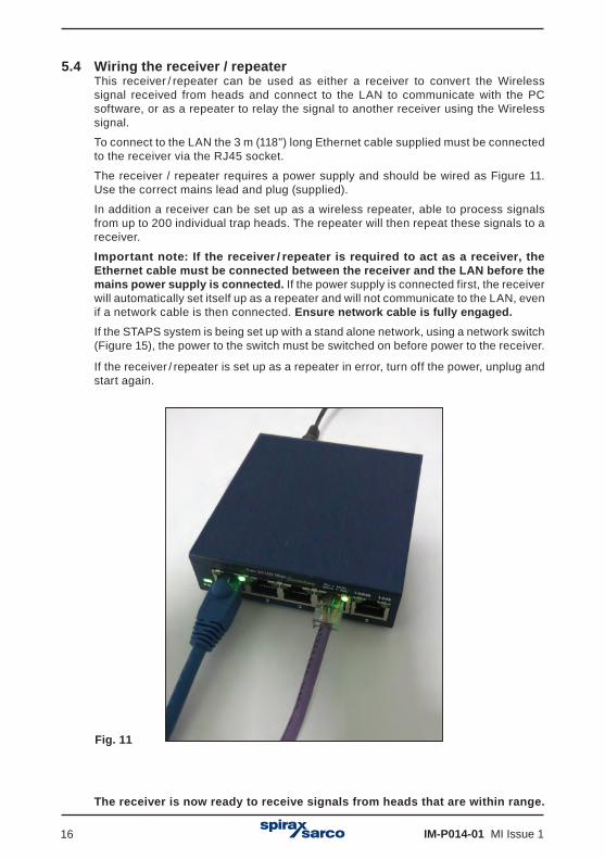
5.4 Wiring the receiver / repeater This receiver / repeater can be used as either a receiver to convert the Wireless
signal received from heads and connect to the LAN to communicate with the PC software, or as a repeater to relay the signal to another receiver using the Wireless signal.
To connect to the LAN the 3 m (118") long Ethernet cable supplied must be connected to the receiver via the RJ45 socket.
The receiver / repeater requires a power supply and should be wired as Figure 11. Use the correct mains lead and plug (supplied).
In addition a receiver can be set up as a wireless repeater, able to process signals from up to 200 individual trap heads. The repeater will then repeat these signals to a receiver.
Important note: If the receiver / repeater is required to act as a receiver, the Ethernet cable must be connected between the receiver and the LAN before the mains power supply is connected. If the power supply is connected first, the receiver will automatically set itself up as a repeater and will not communicate to the LAN, even if a network cable is then connected. Ensure network cable is fully engaged.If the STAPS system is being set up with a stand alone network, using a network switch (Figure 15), the power to the switch must be switched on before power to the receiver.
If the receiver / repeater is set up as a repeater in error, turn off the power, unplug and start again.
The receiver is now ready to receive signals from heads that are within range.
Fig. 11

IM-P014-01 MI Issue 1 17
Fig. 13
Fig. 12
Power supply
RJ45 network cable

IM-P014-01 MI Issue 118
PC
PC
Fig. 14 System using building LAN (network)
Head
Power supply
Wireless signal
Receiver
LAN connection
LAN connection
Power supply
Fig. 15 System using network switch
Head
Power supply
Wireless signal
ReceiverNetwork
switch
Power supply
Power supply

IM-P014-01 MI Issue 1 19
Once connected to the network the receiver icon will show on the network maintenance screen of the software.
Receiver
Fig. 16

IM-P014-01 MI Issue 120
6. Installation of the head unit assembly
Note: Before auctioning any installation observe the 'Safety information' in Section 1.
The STAPS sensor includes the following parts:
- 1 off head and sensor assembly, including the head unit and sensor with top clamp, U bolts and wing nuts, attached with 1 m of cable.
- 1 off lower clamp with 'T' bolt and wing nut. Size ½" – 1¼"
Larger sizes use a top clamp with jubilee clips.
Size 1½", 2"- 2½" and 3"- 4”
- 1 off SAFT LS33600 3.6 V.
Fig. 17
Fig. 18
Fig. 19
Fig. 20
½"¾"1"1¼"
Slot used for size of pipe:

IM-P014-01 MI Issue 1 21
Consider where the STAPS head unit is to be fitted:- The weather - The head unit is IP65 rated.- Wireless signal objections - Will adjacent buildings, pipework or other objects obstruct
the wireless signal from reaching the nearest repeater / receiver? - Interference - Is there any electrical or radio interference that may affect the performance of the STAPS head unit.- Access - Is there sufficient access to the head to change the batteries for maintenance?- Installation - Is there sufficient room at the sensor for the head to be mounted on the
sensor or locally within 1 m?- Lagging - Ensure that any pipe lagging in the area where the STAPS head is to be fitted
is removed before fitting. DO NOT re-lag the STAPS head unit, including the clamp and stem.
6.1 Fitting the battery to the sensor headThe head unit assembly is supplied with a SAFT LS 33600 3.6 V battery loose in the box.
Note: It is highly recommended on initial installation that the battery is fitted whilst the head unit is on a workbench, before it is installed on site.
6.1.2 Unscrew the head cover retaining screw.
Fig. 21

IM-P014-01 MI Issue 122
6.1.3 Turn head cover anticlockwise and align the cover lug with the arrow on the body and pull the cover away from the body.
6.1.4 Remove the packaging from the battery and push it into the holder in the head unit. Ensure that the battery is in the correct orientation as per the orientation marker (+ to top). Note: Only use a SAFT LS 33600 Lithium Thionyl Chloride 3.6 V battery.
It is normal for the LED’s to light momentarily when the battery is fitted.
6.1.5 Refit the cover and retaining screw. Check that the 'O' ring seal is in good condition before refitting the cover, and is correctly seated in place.
Fig. 22
Fig. 23
IM-P014-01 MI Issue 1 23
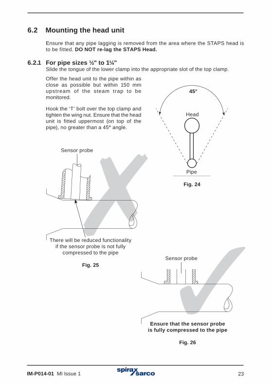
6.2 Mounting the head unit
Ensure that any pipe lagging is removed from the area where the STAPS head is to be fitted. DO NOT re-lag the STAPS Head.
6.2.1 For pipe sizes ½" to 1¼"Slide the tongue of the lower clamp into the appropriate slot of the top clamp.
Offer the head unit to the pipe within asclose as possible but within 150 mm upstream of the steam trap to be monitored.
Hook the ‘T’ bolt over the top clamp and tighten the wing nut. Ensure that the head unit is fitted uppermost (on top of the pipe), no greater than a 45° angle.
45°
Head
Pipe
Fig. 24
There will be reduced functionality if the sensor probe is not fully
compressed to the pipe
Fig. 25
Sensor probe
Ensure that the sensor probe is fully compressed to the pipe
Fig. 26
Sensor probe

IM-P014-01 MI Issue 124
Fig. 27 Fig. 28
Caution: If fitted to a hot pipe, recheck that the clamp is tight after 15 minutes.
Maximum 150 mm

IM-P014-01 MI Issue 1 25
6.2.2 For pipe sizes 1½", 2" - 2.5" and 3" - 4".The larger sizes use jubilee clips rather than a clamp to attach the head unit to the pipe.Separate the jubilee clips and slide over the pipe and loosely tighten the clip to the pipe, allowing room to push the top clamp under.
Ensure that the head unit is fitted uppermost (on top of the pipe), no greater than a 45º angle. Tighten clips into position.
Fig. 29
Fig. 30
Caution: If fitted to a hot pipe, recheck that the clamp is tight after 15 minutes.

IM-P014-01 MI Issue 126
6.3 Fitting the head remote from the sensorIn some circumstances it may be necessary to mount the head away from the sensor. This may be for temperature (head limited to an ambient temperature of 70ºC),signal or space restrictions.
6.3.1 There are two options available for remote mounting. The standard head unit comes with 1m of cable between the sensor and the head itself. The head is secured to the sensor with a 'U' bolt and two wing nuts.
By undoing the wing nuts, the head can be removed from the sensor and re-clamped /attached to another structure in a more convenient place, up to 1 m away. If the
'U' bolt is not suitable, the head can be secured using zip ties (not supplied).
Fig. 31
Fig. 32
Do not attach the head directly to the steam pipe or any other hot structure. Do not lag the STAPS head unit, including the clamp and stem.
IM-P014-01 MI Issue 1 27
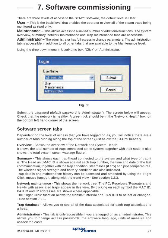
7. Software commissioningThere are three levels of access to the STAPS software, the default level is User:User – This is the basic level that enables the operator to view all of the steam traps being monitored as read only.Maintenance – This allows access to a limited number of additional functions. The system overview, summary, network maintenance and Trap maintenance tabs are accessible. Administrator – The administrator has full access to change parameters. The administration tab is accessible in addition to all other tabs that are available to the Maintenance level.
Using the drop down menu in UserName box, 'Click' on Administrator.
Fig. 33
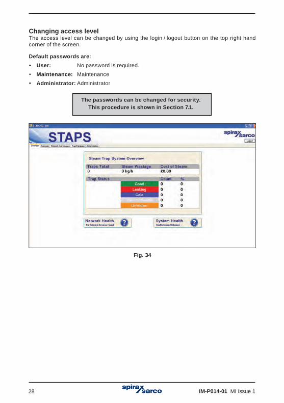
Submit the password (default password is 'Administrator'). The screen below will appear.Check that the network is healthy. A green tick should be in the 'Network Health' box, on the bottom left hand corner of the screen.
Software screen tabsDependent on the level of access that you have logged on as, you will notice there are a number of tabs running along the top of the screen (just below the STAPS header).
Overview - Shows the overview of the Network and System Health. It shows the total number of traps connected to the system, together with their state. It also shows the total system steam wastage figure.
Summary - This shows each trap / head connected to the system and what type of trap it is. The Head unit MAC ID is shown against each trap number, the time and date of the last communication, together with the trap condition, steam loss (if any) and pipe temperatures. The wireless signal strength and battery condition are also indicated.Trap details and maintenance history can be accessed and amended by using the 'Right Click' mouse function, along with the trend view - See section 7.2.3.
Network maintenance - This shows the network tree. The PC, Receivers / Repeaters and Heads with associated traps appear in this view. By clicking on each symbol the MAC ID, PAN ID and IP addresses are shown where applicable.The 'Right Click' function allows the transmit interval and PAN ID's to be set or changed. - See section 7.2.1.
Trap database - Allows you to see all of the data associated for each trap associated to a head.
Administration - This tab is only accessible if you are logged on as an administrator. This allows you to change access passwords, the software language, units of measure and associated costs.
IM-P014-01 MI Issue 128
Fig. 34
The passwords can be changed for security. This procedure is shown in Section 7.1.
Changing access levelThe access level can be changed by using the login / logout button on the top right hand corner of the screen.
Default passwords are:- User: No password is required.- Maintenance: Maintenance - Administrator: Administrator

IM-P014-01 MI Issue 1 29
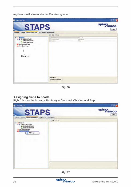
'Click' on the 'Network Maintenance' tab. This will show all of the receivers, repeaters and heads that have connected to the network. Any receivers found will show underneath the computer symbol.
= Computer = Receiver = Repeater = Head = Traps
Fig. 35
The hardware symbols in the software change colour to represent different status. The list below shows the different status.
Computer: Is always red .
Receiver: Is blue . However a red cross will appear if it cannot be reached by the network.
Head: Is green or the icon turns red if it has missed 3 updates, a red cross appears if it cannot be reached by the network, or turns blue if it is a sleepy head.
Traps: Are brown or the icon turns yellow if they are 'undiscovered'.
Repeater: Is always green .
IM-P014-01 MI Issue 130
Assigning traps to headsRight 'click' on the list entry 'Un-Assigned' trap and 'Click' on 'Add Trap'.
Fig. 37
Any heads will show under the Receiver symbol.
Fig. 36
Heads

IM-P014-01 MI Issue 1 31
Fill in all available data To be able to continue the trap number, trap type, pressure and orifice size must be filled in. The trap number is the number / reference that you wish the trap to be identified by for your plant records. These must be unique to each trap / head as duplications will cause an error.
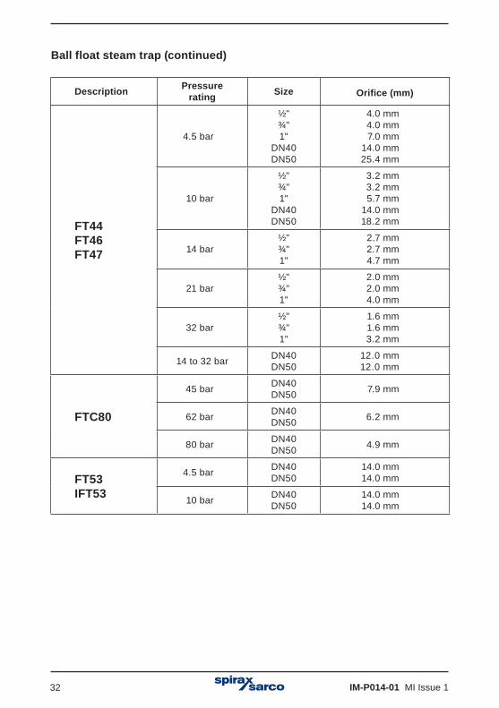
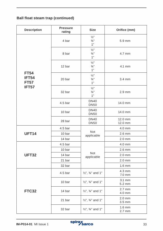
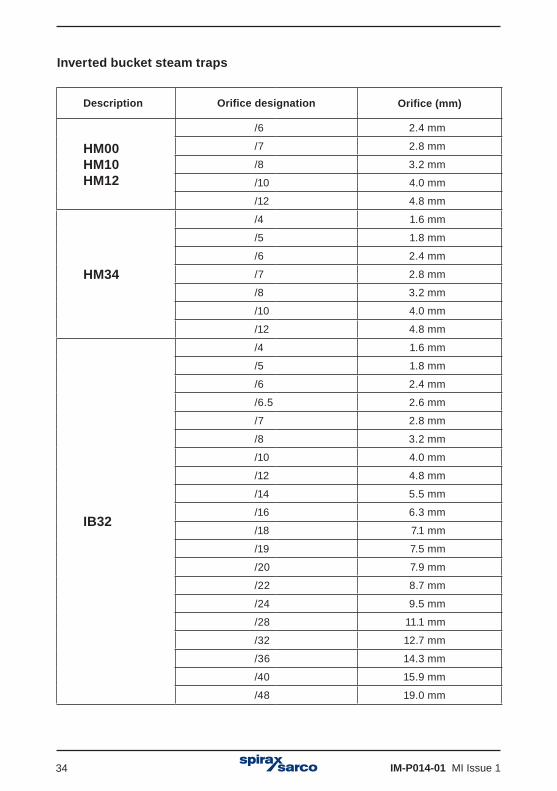
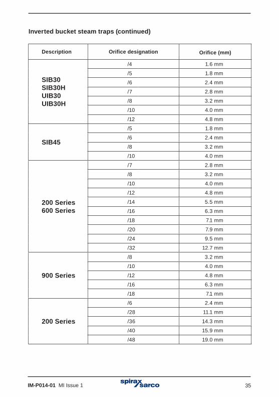
The table below shows the orifice sizes for Spirax Sarco steam traps. Other manufacturers steam trap orifice sizes may be different and therefore it must not be assumed that they will be the same as a similar Spirax Sarco product. Sometimes manufacturers display the orifice size fitted to the trap on the product name-plate. If not the manufacturer will need to be contacted to determine the actual orifice size.
Note: The orifice size and operating pressure is used to calculate the steam leakage. Any inaccuracies in the data entered will lead to inaccuracies in the steam wastage calculation.
Pages 31 to 40Displays the orifice sizes for Spirax Sarco steam traps
Ball float steam trap
Description Pressurerating Size Orifice (mm)
FT10FT43
FT16(½" to 1" only)
FT14 (1½" and 2" only)
FT14HCFTGS14HC(1" only)
4.5 bar
½"¾"1"
DN40DN50
4.0 mm 4.0 mm 7.0 mm14.0 mm 25.4 mm
10 bar
½"¾"1"
DN40DN50
2.7 mm 2.7 mm 5.2 mm14.0 mm18.2 mm
14 bar
½"¾"1"
DN40DN50
2.0 mm 2.0 mm 4.0 mm
12.0 mm12.0 mm
FT14FTGS14FTS14
IFT14IFTGS14(½" and ¾" only)
4.5 bar½"¾"1"
4.0 mm 4.0 mm 5.7 mm
10 bar½"¾"1"
2.6 mm 2.6 mm 4.0 mm
14 bar½"¾"1"
2.0 mm 2.0 mm 3.4 mm
IM-P014-01 MI Issue 132
Ball float steam trap (continued)
Description Pressurerating Size Orifice (mm)
FT44FT46FT47
4.5 bar
½"¾"1"
DN40DN50
4.0 mm 4.0 mm 7.0 mm
14.0 mm25.4 mm
10 bar
½"¾"1"
DN40DN50
3.2 mm 3.2 mm 5.7 mm14.0 mm18.2 mm
14 bar½"¾"1"
2.7 mm 2.7 mm 4.7 mm
21 bar½"¾"1"
2.0 mm 2.0 mm 4.0 mm
32 bar½"¾"1"
1.6 mm 1.6 mm 3.2 mm
14 to 32 bar DN40DN50
12.0 mm12.0 mm
FTC80
45 bar DN40DN50 7.9 mm
62 bar DN40DN50 6.2 mm
80 bar DN40DN50 4.9 mm
FT53IFT53
4.5 bar DN40DN50
14.0 mm14.0 mm
10 bar DN40DN50
14.0 mm14.0 mm
IM-P014-01 MI Issue 1 33
Ball float steam trap (continued)
Description Pressurerating Size Orifice (mm)
FT54IFT54FT57IFT57
4 bar½"¾"1"
5.9 mm
8 bar½"¾"1"
4.7 mm
12 bar½"¾"1"
4.1 mm
20 bar½"¾"1"
3.4 mm
32 bar½"¾"1"
2.9 mm
4.5 bar DN40DN50 14.0 mm
10 bar DN40DN50 14.0 mm
28 bar DN40DN50
12.0 mm12.0 mm
UFT144.5 bar
Notapplicable
4.0 mm
10 bar 2.6 mm
14 bar 2.0 mm
UFT32
4.5 bar
Notapplicable
4.0 mm
10 bar 2.6 mm
14 bar 2.0 mm
21 bar 2.0 mm
32 bar 1.6 mm
FTC32
4.5 bar ½", ¾" and 1" 4.3 mm7.0 mm
10 bar ½", ¾" and 1" 3.1 mm5.2 mm
14 bar ½", ¾" and 1" 2.7 mm4.0 mm
21 bar ½", ¾" and 1" 2.0 mm3.5 mm
32 bar ½", ¾" and 1" 1.6 mm2.7 mm
IM-P014-01 MI Issue 134
Inverted bucket steam traps
Description Orifice designation Orifice (mm)
HM00HM10HM12
/6 2.4 mm
/7 2.8 mm
/8 3.2 mm
/10 4.0 mm
/12 4.8 mm
HM34
/4 1.6 mm
/5 1.8 mm
/6 2.4 mm
/7 2.8 mm
/8 3.2 mm
/10 4.0 mm
/12 4.8 mm
IB32
/4 1.6 mm
/5 1.8 mm
/6 2.4 mm
/6.5 2.6 mm
/7 2.8 mm
/8 3.2 mm
/10 4.0 mm
/12 4.8 mm
/14 5.5 mm
/16 6.3 mm
/18 7.1 mm
/19 7.5 mm
/20 7.9 mm
/22 8.7 mm
/24 9.5 mm
/28 11.1 mm
/32 12.7 mm
/36 14.3 mm
/40 15.9 mm
/48 19.0 mm
IM-P014-01 MI Issue 1 35
Inverted bucket steam traps (continued)
Description Orifice designation Orifice (mm)
SIB30SIB30HUIB30UIB30H
/4 1.6 mm
/5 1.8 mm
/6 2.4 mm
/7 2.8 mm
/8 3.2 mm
/10 4.0 mm
/12 4.8 mm
SIB45
/5 1.8 mm
/6 2.4 mm
/8 3.2 mm
/10 4.0 mm
200 Series600 Series
/7 2.8 mm
/8 3.2 mm
/10 4.0 mm
/12 4.8 mm
/14 5.5 mm
/16 6.3 mm
/18 7.1 mm
/20 7.9 mm
/24 9.5 mm
/32 12.7 mm
900 Series
/8 3.2 mm
/10 4.0 mm
/12 4.8 mm
/16 6.3 mm
/18 7.1 mm
200 Series
/6 2.4 mm
/28 11.1 mm
/36 14.3 mm
/40 15.9 mm
/48 19.0 mm
IM-P014-01 MI Issue 136
Inverted bucket steam traps (continued)
Description Pressurerating Size Orifice (mm)
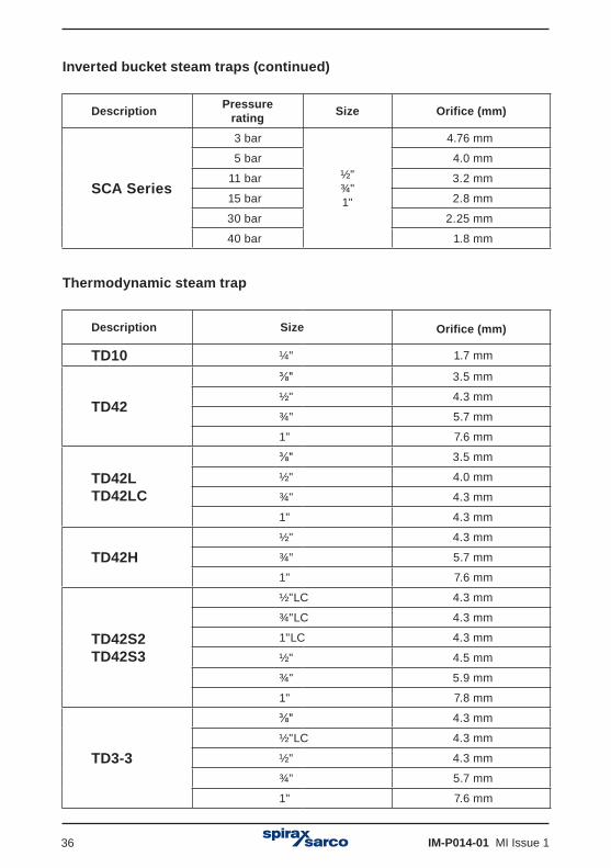
SCA Series
3 bar
½"¾"1"
4.76 mm
5 bar 4.0 mm
11 bar 3.2 mm
15 bar 2.8 mm
30 bar 2.25 mm
40 bar 1.8 mm
Thermodynamic steam trap
Description Size Orifice (mm)
TD10 ¼" 1.7 mm
TD42
⅜" 3.5 mm
½" 4.3 mm
¾" 5.7 mm
1" 7.6 mm
TD42LTD42LC
⅜" 3.5 mm
½" 4.0 mm
¾" 4.3 mm
1" 4.3 mm
TD42H½" 4.3 mm
¾" 5.7 mm
1" 7.6 mm
TD42S2TD42S3
½"LC 4.3 mm
¾"LC 4.3 mm
1"LC 4.3 mm
½" 4.5 mm
¾" 5.9 mm
1" 7.8 mm
TD3-3
⅜" 4.3 mm
½"LC 4.3 mm
½" 4.3 mm
¾" 5.7 mm
1" 7.6 mm
IM-P014-01 MI Issue 1 37
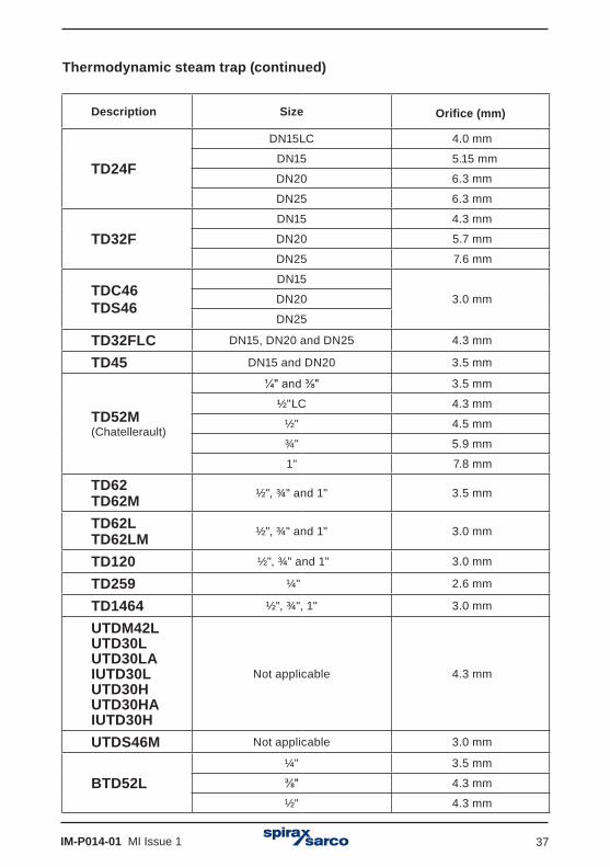
Thermodynamic steam trap (continued)
Description Size Orifice (mm)
TD24F
DN15LC 4.0 mm
DN15 5.15 mm
DN20 6.3 mm
DN25 6.3 mm
TD32FDN15 4.3 mm
DN20 5.7 mm
DN25 7.6 mm
TDC46TDS46
DN15
3.0 mmDN20
DN25
TD32FLC DN15, DN20 and DN25 4.3 mm
TD45 DN15 and DN20 3.5 mm
TD52M(Chatellerault)
¼" and ⅜" 3.5 mm
½"LC 4.3 mm
½" 4.5 mm
¾" 5.9 mm
1" 7.8 mm
TD62TD62M ½", ¾" and 1" 3.5 mm
TD62LTD62LM ½", ¾" and 1" 3.0 mm
TD120 ½", ¾" and 1" 3.0 mm
TD259 ¼" 2.6 mm
TD1464 ½", ¾", 1" 3.0 mm
UTDM42LUTD30LUTD30LAIUTD30LUTD30HUTD30HAIUTD30H
Not applicable 4.3 mm
UTDS46M Not applicable 3.0 mm
BTD52L¼" 3.5 mm
⅜" 4.3 mm
½" 4.3 mm
IM-P014-01 MI Issue 138
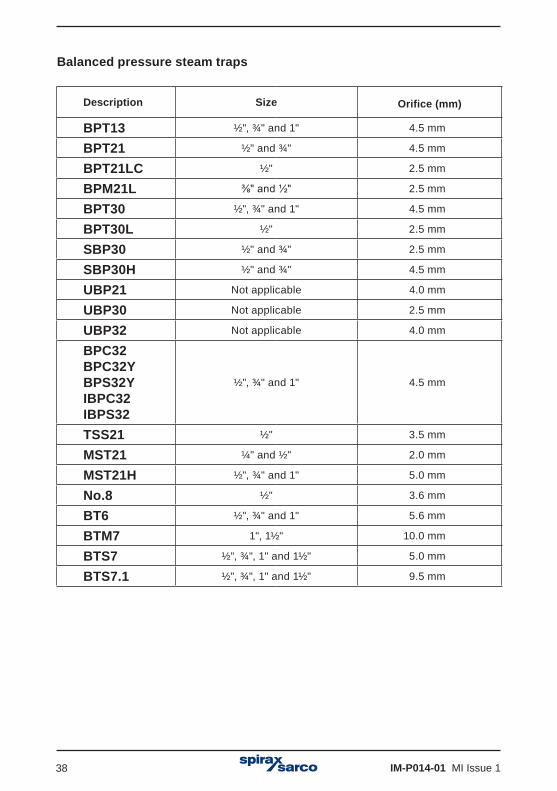
Balanced pressure steam traps
Description Size Orifice (mm)
BPT13 ½", ¾" and 1" 4.5 mm
BPT21 ½" and ¾" 4.5 mm
BPT21LC ½" 2.5 mm
BPM21L ⅜" and ½" 2.5 mm
BPT30 ½", ¾" and 1" 4.5 mm
BPT30L ½" 2.5 mm
SBP30 ½" and ¾" 2.5 mm
SBP30H ½" and ¾" 4.5 mm
UBP21 Not applicable 4.0 mm
UBP30 Not applicable 2.5 mm
UBP32 Not applicable 4.0 mm
BPC32BPC32YBPS32YIBPC32IBPS32
½", ¾" and 1" 4.5 mm
TSS21 ½" 3.5 mm
MST21 ¼" and ½" 2.0 mm
MST21H ½", ¾" and 1" 5.0 mm
No.8 ½" 3.6 mm
BT6 ½", ¾" and 1" 5.6 mm
BTM7 1", 1½" 10.0 mm
BTS7 ½", ¾", 1" and 1½" 5.0 mm
BTS7.1 ½", ¾", 1" and 1½" 9.5 mm

IM-P014-01 MI Issue 1 39
Bimetallic steam trap
Description Size Orifice (mm)
SSM21 ½" and ¾" 2.7 mm
SM21 ½" and ¾" 2.7 mm
SM24 ½" and ¾" 3.9 mm
SM24H SMC32 ½" and ¾" 5.7 mm
SMC32Y ½", ¾" and 1" 6.3 mm
SM45
½" 2.9 mm
¾" 6.8 mm
1" 6.8 mm
1½" 6.8 mm
USM21 Not applicable 8.5 mm
SP80SP100 3" and 4"
Seat and 40 = 34.6 mmSeat and 46 = 41.3 mmSeat and 54 = 50.1 mmSeat and 66 = 62.8 mm
HP45 ½", ¾" and 1" 6.3 mm
HP80HP100HP150HP210
½", ¾" and 1" 3.0 mm
ABL405ABL505
1½" (DN40)2" (DN50) 18.3 mm
ABL414ABL514
1½" (DN40)2" (DN50) 16.7 mm
ABL425ABL525
1½" (DN40) 2" (DN50) 13.6 mm
ABL440ABL540
1½" (DN40)2" (DN50) 10.3 mm
PBX20 ½", ¾" and 1" 6.2 mm
PBX30 ½", ¾" and 1" 6.2 mm
PBX40 ½", ¾" and 1" 10.4 mm
PBX50 ½", ¾" and 1" 7.5 mm
T3 ⅜", ¼", ½" and ¾" 13.5 mm

IM-P014-01 MI Issue 140
Fig. 38
Other data can be filled in at a later date required - See Section 7.2.5.Save and close the window.
Liquid expansion trap
Description Size Orifice (mm)Effective orifice (mm²)
Bydrain ½" and ¾" 8.0 mm
No. 8 ½" 3.8 mm

IM-P014-01 MI Issue 1 41
Drag and drop the new trap onto the head reference, enduring that the correct trap is allocated to its corresponding head.
'Right Click' on both the trap and the head and click on 'Update Configuration'.
Repeat to add traps to all heads. Only one trap can be assigned to a head.
Fig. 40
Fig. 39

IM-P014-01 MI Issue 142
7.1 System administration'Click' on the administration tab. From here you can change or update the system data.
CO2This allows you to change or add the cost (in monetary value) that it costs your plant to raise a tonne of steam. This is used to calculate the total cost of steam wastage.
LanguageYou can select the language that the software uses from the drop down list. The default is GB- English.
PasswordsEach level of access to the STAPS software has its own password protection. The default passwords are:-
User: UserMaintenance: MaintenanceAdministrator: Administrator
These can be individually changed here in the administration tab. Only the administrator has access to change the passwords. (If you have logged in as a User or Maintenance, the administration tab is not accessible).
Remember to make a note of any changes you make to the passwords, as you will need to enter them the next time you login to the software.
Site detailsYou can add your company name and site details here.
UnitsThis allows you to change the engineering units that the system uses. Select the units you require from the drop down menu.
REMEMBER to save any changes you make by clicking the save button on the top left hand corner of this screen.

IM-P014-01 MI Issue 1 43
7.2 MAC address and PAN-IDThe MAC address is a unique number to the piece of equipment it is attached to. This cannot be changed and will remain with the product for its lifetime.
PAN-ID
The PAN-ID however is changeable and can be done so through the network administration screen.
Why change the PAN-ID?The PAN address is effectively a signal channel. As long as the PAN-ID of the receiver /repeater and heads are all the same, they will all communicate with each other throughout your network. However if there are any other products using wireless software close by, your receiver may pick up signals from them as well. This means that if a neighbouring factory is using the same wireless network, there could be interference.
We therefore suggest that the PAN-ID is changed to a number that is unique to your site. Change the last four numbers of the PAN ID only. It maybe that you may wish to have two STAPS systems running in parallel, but do not want them to get mixed up together. Changing the PAN-ID's for two different systems to two separate addresses will allow both systems to run independently.
The PAN-ID is set to zero as a default - See Figure 42.
Fig. 41
Fig. 42

IM-P014-01 MI Issue 144
7.2.1 How to change the Head / Receiver PAN IDRight click on the Head / Receiver icon and click Set PAN ID.
Click OK to confirm.
Change the PAN ID to a suitable number. Changing the last three or four digits is normally enough. The default PAN ID is all zero's.
Fig. 43
Fig. 44

IM-P014-01 MI Issue 1 45
7.2.2 Adding a ReceiverOnly one Receiver can be used on the main network. Should there be an attempt to add an additional Receiver onto the same network, it will automatically set it self up as a repeater that will communicate with the existing Receiver.
However, a Receiver can be added to a separate subnet. See Section 7.3.

IM-P014-01 MI Issue 146
7.2.3 Trend viewThe Trend View allows you to see the trend for steam loss and line temperature for each head.
Click on the Summary tab.Right click on the head icon that you wish to see.
Fig. 45

IM-P014-01 MI Issue 1 47
Click on 'Trend View'
The top graph shows the Steam loss in mass units for a given period of time. The scales are adjustable using the tool buttons.
The bottom graph shows the trap temperature trend. This is also adjustable.
Fig. 46

IM-P014-01 MI Issue 148
7.2.4 Maintenance HistoryThis allows you to collate a maintenance history for each trap / head.
In the summary tab, Right Click on the head you wish to create a history.
Fig. 47
Fig. 48
You can add the history data here. Remember to click on the save button when you have finished.
Click on Maintenance History
IM-P014-01 MI Issue 1 49
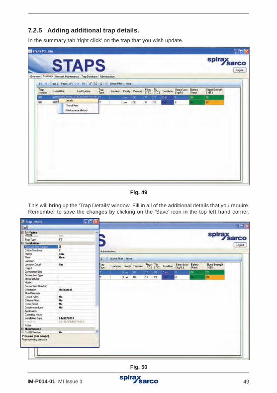
7.2.5 Adding additional trap details.In the summary tab 'right click' on the trap that you wish update.
This will bring up the 'Trap Details' window. Fill in all of the additional details that you require. Remember to save the changes by clicking on the 'Save' icon in the top left hand corner.
Fig. 49
Fig. 50

IM-P014-01 MI Issue 150
7.3 Adding a receiver to a different Subnet
If the installation is very large, the local network (LAN) may be set up into a number of different Subnets. This means that the STAPS receivers may have to communicate across them to pass the data back to the PC.
7.3.1 Static ReceiverStatic Receivers are Receivers that are located on a different IP subnet to the PC application. They have to be added manually because the PC applications discovery protocol only works within the subnet.
7.3.2 Adding a Static Receiver1. Connect a Receiver to a different IP subnet to the PC application.
2. Power on the Receiver.
3. Record the IP address of the Receiver. If not known, use the CLI command 'GIP'.
4. On the PC application, Network Maintenance tab, right click on the 'Computer Icon'.
5. Select 'Add Receiver'.
Fig. 51

IM-P014-01 MI Issue 1 51
6. In the dialogue box, set the IP address of the Receiver, the Transmit Interval and PAN ID.
Fig. 52
7. The Receiver will initially show up as undiscovered, with the entered IP address used as the Receiver name.
8. When the next discovery runs, the PC application will contact the Receiver. The Receiver will return its Xbee MAC address. The PC application will show the Receiver as discovered, with the Xbee MAC address being used as the Receiver name.
9. If the PC application is not able to contact the Receiver using the entered IP address, then the Receiver remains as undiscovered in the Network Maintenance tab. Try ‘Pinging’ the IP address of the Receiver from the PC that is running the STAPS application. If it doesn’t respond to the Ping, then there is probably a network setup problem.
7.3.3 Changing IP Address of Static Receiver1. If the IP address of the Receiver changes, then the PC application must be updated.
2. First remove the Receiver. To do this right click on the Receiver in the network maintenance tab and select Delete receiver.
3. Once removed, re-add the receiver using the new IP address, following the procedure above. Note: We suggest that you speak with your network administrator regarding assigning a static IP address for this receiver.

IM-P014-01 MI Issue 152
7.4 OperationWhen the system is operational the overview screen (below) will show the number of traps connected, the condition of each and total steam wastage together with CO2 cost.
Fig. 53
7.4.1 System healthError At least 1 trap failing.Warning At least 1 trap leaking or cold.Good No traps, leaking failing or cold.Unknown The condition of all traps is undiscovered.

IM-P014-01 MI Issue 1 53
7.4.2 Network healthBad Less than 80% of heads responding.Warning 80 - 90% of receivers are responding.Good More than 90% of receivers are responding.Unknown No devices are discovered yet or in the configuration file.
Fig. 54

IM-P014-01 MI Issue 154
7.4.3 Head LED operationThere are two coloured LED's that illuminate in the window on the top of the head unit:
Flashing Orange LED - Indicates that the battery power is low. This can be verified on the software summary tab on the PC.
Flashing Red LED - Indicates that the head has identified a leak from the associated steam trap.
Fig. 55

IM-P014-01 MI Issue 1 55
7.5 Deleting the trap, head or receiver from the software
7.5.1 Deleting a trap from the software
An occasion may arise where a trap has been made redundant and is removed. The trap data must be removed from the database.
If the receiver or head is being put into storage the PAN ID's must be returned to zero.
If the heads and associated receiver are being relocated, but staying as associates, the PAN ID's can be left as set.
'Drag and drop' the trap into the 'Un-Assigned Trap' folder.
'Right click' on the trap to be deleted (now showing in the 'Un-Assigned Traps') and click 'Delete'.
Fig. 56

IM-P014-01 MI Issue 156
7.5.2 Deleting a head from the software'Right click' on the head to be deleted and click on 'Set PAN ID' and set to zero.
Fig. 57
Remove the battery from the head.
Return to PC and in software, 'Right click' on the head to be deleted and click 'Delete'.
Note: The software will not allow you to delete a head if a trap is still assigned to it.
IM-P014-01 MI Issue 1 57
Fig. 58
7.5.3 Deleting a receiver from the softwareAs with the head, the PAD ID must be returned to zero.
Remove power supply and ethernet cable from the receiver.
Return to the PC. 'Right click' on the receiver and click on 'delete'.
Note: If a receiver is deleted whilst heads are still connected to it, the heads will appear in the 'Un-Discovered Traps' folder.

IM-P014-01 MI Issue 158
8. Spare partsOnly the parts listed below are available for the STAPS system. No other parts are supplied as spares.
Fig. 59
��������������
How to order sparesAlways order spare parts by using the description given in the column headed 'Available spares' and state the size and unit nomenclature that they are intended for.
Example:1 off Battery spares kit (SAFT LS 33600 3.6 V battery) and1 off Wall mounting spares kitThese spares are for a DN15 STAPS wireless steam trap monitoring system.
Available spares
Battery (SAFT LS 33600 3.6 V battery) 1'O' ring spares kit 2Head mounting bracket, 'U' bolt and wing nuts 8, 9, 10 and 19Ethernet cable spares kit 15Clamp, 'T' bolt and wing nut 5, 6 and 7Power supply (UK) spares kit 11 and 14Power supply (US) spares kit 12 and 14Power supply (EU) spares kit 13 and 14Front cover spares kit 3 and 4Spare receiver mounting kit 6, 17 and 18
3 1
5 6
8
10
9
4 2
19

IM-P014-01 MI Issue 1 59
1817 16
15 1114
Fig. 60
12
13
UK
US
EU

IM-P014-01 MI Issue 160
9. Fault findingFault condition Primary cause Secondary cause Tertiary cause Remedy
1 No
updates received
Low signal
Location Head unit or receiver out of range
Install intellegent head or additional receiver. Existing receiver may be able to be resighted, but ensure if moving it other head signals are not lost.
Obstruction
Temporary Check that an obstacle like a vehicle has not parked between the head / repeater and the receiver. Remove obstacle to reinstate connection.
PermanentCheck that a perminant obstacle like a new wall / barrier or machinery has not been erected between the head / repeater and the receiver. Install either an intellegent head or additional receiver.
Battery Low battery power Replace battery.Receiver / Repeater /Head fault
Software / Hardware fault Return to supplier.
Overheating
Head unit fitted to pipe with a temperature exceeding 425°C
Incorrect application.
Remote head fitted to a pipe / surface allowing the ambient temperature to rise above 70°C
Move remote head to a cooler pipe / surface.
Repeater / receiver fitted to a pipe / surface allowing the ambient temperature to rise above 70°C
Move remote head to a cooler pipe / surface.
Damaged head unit /receiver Check for damage and replace if necessary.
Physically moved
Head unit has been moved more than150 mm away from the upstream side of the steam trap
Move the head unit to within 150 mm of the steam trap.
Configuration has been changed
Incorrect PAN-ID PAN-ID has been changed Assign correct PAN-ID.
Interval time has been changed
Interval times has been set to a long period Check interval time and return to default setting of 15 minutes.
Trap configuration has been changed
Incorrect trap type has been configured Re-configure the correct trap type.
Head unit has been moved to different trap Move Head Unit back to original trap, or reconfigure trap type.
Trap has been changed for different type Reconfigure trap type.
Signal interference
Electrical motors /switchgear have been sited near to head unit /receiver / repeater
Assess position of electric motor / switchgear and move if possible.
IM-P014-01 MI Issue 1 61
Fault condition Primary cause Secondary cause Tertiary cause Remedy
1 No
updates received
Low signal
Location Head unit or receiver out of range
Install intellegent head or additional receiver. Existing receiver may be able to be resighted, but ensure if moving it other head signals are not lost.
Obstruction
Temporary Check that an obstacle like a vehicle has not parked between the head / repeater and the receiver. Remove obstacle to reinstate connection.
PermanentCheck that a perminant obstacle like a new wall / barrier or machinery has not been erected between the head / repeater and the receiver. Install either an intellegent head or additional receiver.
Battery Low battery power Replace battery.Receiver / Repeater /Head fault
Software / Hardware fault Return to supplier.
Overheating
Head unit fitted to pipe with a temperature exceeding 425°C
Incorrect application.
Remote head fitted to a pipe / surface allowing the ambient temperature to rise above 70°C
Move remote head to a cooler pipe / surface.
Repeater / receiver fitted to a pipe / surface allowing the ambient temperature to rise above 70°C
Move remote head to a cooler pipe / surface.
Damaged head unit /receiver Check for damage and replace if necessary.
Physically moved
Head unit has been moved more than150 mm away from the upstream side of the steam trap
Move the head unit to within 150 mm of the steam trap.
Configuration has been changed
Incorrect PAN-ID PAN-ID has been changed Assign correct PAN-ID.
Interval time has been changed
Interval times has been set to a long period Check interval time and return to default setting of 15 minutes.
Trap configuration has been changed
Incorrect trap type has been configured Re-configure the correct trap type.
Head unit has been moved to different trap Move Head Unit back to original trap, or reconfigure trap type.
Trap has been changed for different type Reconfigure trap type.
Signal interference
Electrical motors /switchgear have been sited near to head unit /receiver / repeater
Assess position of electric motor / switchgear and move if possible.
IM-P014-01 MI Issue 162
Fault condition Primary cause Secondary cause Tertiary cause Remedy
2 Trap shows it is cold when steam is on
Trap is out of service Check again once trap is back in service.Trap is blocked or isolated Unblock trap. Unisolate if safe to do so.
Incorrect head unit orientation on pipe
Ensure the head unit is fitted with the head pointing vertically upwards or no more than 45° from top dead centre.
Head unit fitted to outlet of trap rather than inlet
Ensure that head unit is fitted to the upstream side and no more that 150 mm of the steam trap.
Poor contact with the steam pipe
Ensure that the steam pipe is clean, free from rust and scale. Check that the head unit clamp /jubilee clips are tight. The deand unit sensor must be in direct contact with the steam pipe. The head unit must no be clamped over the top of any pipe lagging.
3 Temperature
is unreasonably high (greater that 1000°C)
Head unit temperature sensor (PT100) has failed
Contact Spirax Sarco.
4 Trap
condition incorrect
Steam trap alternates between good and medium leakShows leak condition, but steam leakage at zeroTrap shows ok, but steam is turned off
Residue heat remaining in pipe with water flow Allow heat to disapate and re-check.
Trap shows ok, but shows a leakage Intermittent trap failure Monitor, repair or replace trap.
Shows unreasonable leakage for trap
Asigned trap configured incorrectly. Incorrect orifice size, pressure or trap type selected
Check trap configuration. Ensure trap type, orifice size and pressure are correct.
5 System
steam cost incorrect
Change steam cost in software configuration.

IM-P014-01 MI Issue 1 63
Fault condition Primary cause Secondary cause Tertiary cause Remedy
2 Trap shows it is cold when steam is on
Trap is out of service Check again once trap is back in service.Trap is blocked or isolated Unblock trap. Unisolate if safe to do so.
Incorrect head unit orientation on pipe
Ensure the head unit is fitted with the head pointing vertically upwards or no more than 45° from top dead centre.
Head unit fitted to outlet of trap rather than inlet
Ensure that head unit is fitted to the upstream side and no more that 150 mm of the steam trap.
Poor contact with the steam pipe
Ensure that the steam pipe is clean, free from rust and scale. Check that the head unit clamp /jubilee clips are tight. The deand unit sensor must be in direct contact with the steam pipe. The head unit must no be clamped over the top of any pipe lagging.
3 Temperature
is unreasonably high (greater that 1000°C)
Head unit temperature sensor (PT100) has failed
Contact Spirax Sarco.
4 Trap
condition incorrect
Steam trap alternates between good and medium leakShows leak condition, but steam leakage at zeroTrap shows ok, but steam is turned off
Residue heat remaining in pipe with water flow Allow heat to disapate and re-check.
Trap shows ok, but shows a leakage Intermittent trap failure Monitor, repair or replace trap.
Shows unreasonable leakage for trap
Asigned trap configured incorrectly. Incorrect orifice size, pressure or trap type selected
Check trap configuration. Ensure trap type, orifice size and pressure are correct.
5 System
steam cost incorrect
Change steam cost in software configuration.

IM-P014-01 MI Issue 164
10. Certification and approvalsUnited States - Standards used for Certification:FM3600, FM3610, FM3810, ASME / ISA 60079-0 and ASME / ISA 60079-11
Canada Standards used for Certification:CSA 1010.1, CSA C22.2 No.157, CSA C22.2 No.25, CAN / CSAE 60079-0 and CAN / CSA 60079-11
Note: The above approvals are only valid if the product is installed using the genuine supplied component parts and accessories, including consumable items such as batteries and power leads.

IM-P014-01 MI Issue 1 65
11. Technical dataHead unit: See Section 6 for mounting options.Integral battery Lithium Thionyl ChlorideMaximum altitude 3 000 m (0.7 bar atmospheric)
Ambient temperature range -29 to +70°C (battery life based poling at 15 minute intervals at an ambient temperature of 20°C.Maximum pipe temperature 425°C Maximum relative humidity 95% Enclosure rating IP66Output IEE 802-15 2.4 GHzVisual indicators LED
Receiver / RepeaterPower Mains powered 100 to 250 Vac, 50 to 60 Hz
Current ac - 0.5 A, 100 Vac dc - 1.5 A, 12 V
Connector ac - 2 pin IEC 320-C8 3 pin UK, US and European mains plug dc - 2 pin IP65
ConnectorMaximum altitude 3000 m (0.7 bar atmospheric)Ambient temperature range -29 to +70°CMaximum relative humidity 95%Enclosure rating IP65 (Excluding external power supply)Visual indicators LEDInput / Output (I/O) IEE 802.15 2.4 GHz RJ45 port
STAPS RF securityThe RF side of the network implements 128-bit advanced encryption standard (AES) cipher using a randomly generated key transmitted to the joining node by the network co-ordinator device when the node requests to join the network. All subsequent exchanges are encrypted using the key. The network header, APS header (this is the part of the frame that supports routeing, acknowledgement, binding and address maps) and application data are all authenticated with 128-bit AES. Additionally a checksum is performed on these fields and is appended as a 4-byte message integrity code (MIC) to the end of the packet. The MIC allows receiving devices to ensure the message has not been changed. If a device receives a packet and the MIC does not match the devices own checksum of the data, the packet is dropped.The network header of the encrypted packets also includes a 32-bit frame counter; each device on the network maintains a 32-bit frame counter that is incremented for each transmission. Devices track the last known 32-bit counter for each of its neighbours. If a device receives a packet from a neighbour with a smaller frame counter than it has previously seen the packet is discarded thereby protecting against 'replay' attacks.

IM-P014-01 MI Issue 166
Cat5 cableCat5 cable is used to physically connect separate networked devices. The cable can be installed permanently as part of the site infrastructure (structured cabling) and or be used as short 'patch' cables to connect a networkable device to a switch or hub through the structured cabling using RJ45 plugs and wall sockets.
DHCP - Dynamic Host Configuration ProtocolDynamic host configuration protocol is a network service provided by a local machine (usually a server) that will automatically allocate an IP address to a networkable device that wishes to join a LAN. If a DHCP service is not locally available then the device will need an IP address to be manually configured.
EncryptionEncryption refers to the encoding of information using a pre-agreed cipher key prior to over-the-air radio transmission. The same “key” is needed to decrypt the messages into a useable form at the receiver.
EthernetEthernet is the physical transport medium for a networking protocol (eg TCP / IP). The Ethernet standards encompass coaxial, twisted pair (cat5) and fiber optic physical media interfaces running at transmission speeds from ten megabit to a hundred gigabit per second.
Ethernet CableSee Cat5 cable.
HeadAn individual trap sensing device which is networkable.
HexadecimalCounting system using base 16 as opposed to a decimal system using base 10. Extensively used in computer programming and network addressing applications. Also called hex.
HubSee Switch.
Intelligent HeadA normal head unit which has received additional configuration in order for it to act as a repeater device. The head will wake up and perform the normal trap analysis functions and then it will arbitrate to offer a re-transmission service for any other heads which are on the network but not directly in range of a receiver or repeater.
IP Address – Internet Protocol AddressA set of four binary octets represented in decimal by four numbers between zero and 255. IP addresses can be manually (static IP) or automatically (DHCP assigned) allocated to a network entity for identification purposes.
12. Technical glossary

IM-P014-01 MI Issue 1 67
LAN - Local Area NetworkA Local Area Network is a logical group of interconnected devices in a limited geographical area such as a home, school, factory, or office building.
MAC Address – Media Access ControlA media access control address is a unique number (in the form of six groups of two hexadecimal digits) that is assigned to a networkable device at the time of manufacture. As the number is unique it can be used to identify and address particular members of a network.
Network SwitchThe Network Switch is used to simulate a LAN when the device is set up with a stand alone network. It allows hard wired items such as a receiver and the PC to to be connected together, taking the place of a LAN.
Orifice SizeThe orifice size is the size of the hole in the trap seat that the condensate passes through.
PAN – Personal Area NetworkA collection of co-operative devices sharing a similar geographical location and having a common PAN-ID.
PAN-ID - Personal area network identificationA PAN-ID is a number allocated to a network co-ordinator (receiver). Heads will base a decision on which network to join based on their PAN-ID. The default PAN-ID is zero which means that the device will join any network and then assume the PAN-ID of that network. A device with a non-zero PAN-ID allocated by the user will only join a network that has the same non-zero PAN-ID.
Ping or PingingThis is a procedure that sends a signal from the PC to another devices IP address to see if it responds. This tests the network to ensure that the route of communication is clear.
ReceiverA receiver is a physical device that creates and manages a PAN. It also functions as a gateway between the PAN and the Ethernet network.
RepeaterA repeater is a physical device not attached to the Ethernet network but forming part of a PAN. The function of the repeater is to extend the range of the network, where mains power is available.
RJ45 - Registered Jack 45RJ45 plugs and sockets along with cat5 cable are used to connect devices together to form a network. Sometimes called an 8P8C connector.

IM-P014-01 MI Issue 168
STAPSSpirax Total Acoustic Performance System.
Static IP AddressA static ip address is configured manually on a networkable device in order to identify that device on a network; as opposed to an automatic configuration – see DHCP.
Switch (Hub) A switch is a physical device used to connect members of a local area network via Ethernet cabling and hardware.
TCP / IP - Transmission control protocol / internet protocolAn internationally agreed suite of communications software used to implement computer networks that can range from a home wireless connection up to the internet. TCP / IP provides a framework enabling data communications to be formatted, addressed and routed between networked devices and between networks themselves.
Trap NumberThis is the identification number given to a specific steam trap on a plant.

IM-P014-01 MI Issue 1 69

IM-P014-01 MI Issue 170

IM-P014-01 MI Issue 1 71

IM-P014-01 MI Issue 172
Related Documents