IRC: 15-2011 STANDARD SPECIFICATIONS AND CODE OF PRACTICE FOR CONSTRUCTION OF CONCRETE ROADS (FOURTH REVISION) INDIAN ROADS CONGRESS 2011

Welcome message from author
This document is posted to help you gain knowledge. Please leave a comment to let me know what you think about it! Share it to your friends and learn new things together.
Transcript

IRC: 15-2011
STANDARD SPECIFICATIONSAND
CODE OF PRACTICEFOR
CONSTRUCTION OF CONCRETEROADS
(FOURTH REVISION)
INDIAN ROADS CONGRESS2011

Digitized by the Internet Archiive
in 2014
https://archive.org/details/govlawircy201115

IRC: 15-2011
STANDARD SPECIFICATIONSAND
CODE OF PRACTICEFOR
CONSTRUCTION OF CONCRETEROADS
(FOURTH REVISION)
Published by
INDIAN ROADS CONGRESSKama Koti Marg,
Sector 6, R.K. Puram,
New Delhi - 110 022
Price : Rs. 800/-
(Packing & Postage charges extra)

IRC: 15-2011
First Published
First Revision
Second Revision
Third Revision
Reprinted
Reprinted
Fourth revision
Reprinted
July, 1965
December, 1970
December, 1981
February, 2002
September, 2003
October, 2005
May, 2011
April, 2014
(AH Right Reserved. No part of this publication shall be reproduced, translated
transmitted in any form or by any means without the permission of the
Indian Roads Congress)
Printed at India Offset Press, New Delhi-110 064
(1000 Copies)

IRC: 15-2011
CONTENTS
Page No.
Personnel of the Highways Specifications and Standards Committee (i)
1. Introduction 1
2. Scope 2
3. Materials 3
4. Proportioning of Concrete 10
5. Tools, Equipments, Machines and Appliances 15
6. Preparation of Subgrade, Sub-base and Laying of Separation Membrane 20
7. Weather Limitations 25
8. Joints 30
9. Storage of Materials and Preparation for Construction 47
10. Construction 49
11. Trial Length 69
12. Quality Control 73
13. Opening to Traffic 93


IRC: 15-2011
PERSONNEL OF THE HIGHWAYS SPECIFICATIONS ANDSTANDARDS COMMITTEE
(As on 22 nd October, 2010)
1. Sinha, A.V.
(Convenor)
2. Puri, S.K.
(Co-Convenor)
3. Kandasamy, C.
(Member-Secretary)
4. Datta, P.K.
5. Gupta, K.K.
6. Sinha, S.
7. Kadiyali, Dr. L.R.
8. Katare, P.K.
9. Jain, Dr. S.S.
10. Reddy, K Siva
11. Basu, S.B.
12. Bordoloi, A.C.
13. Rathore, S.S.
14. Pradhan, B.C.
15. Prasad, D.N.
16. Kumar, Ashok
17. Kumar, Kamlesh
18. Krishna, Prabhat
19. Patankar, V.L.
20. Kumar, Mahesh
21. Bongirwar, P L.
Director General (RD) & Spl. Secretary, Ministry of
Road Transport & Highways, New Delhi
Addl. Director General, Ministry of Road
Transport & Highways, New Delhi
Chief Engineer (R) S&R, Ministry of Road
Transport & Highways, New Delhi
Members
Executive Director, Consulting Engg. Services (I) Pvt. Ltd.,
New Delhi
Chief Engineer (Retd.), Haryana PWD, Faridabad
Addl. Chief Transportation Engineer, CIDCO, Navi Mumbai
Chief Executive, L.R. Kadiyali & Associates, New Delhi
Director (Projects-Ill), National Rural Roads Development
Agency, (Ministry of Rural Development), New Delhi
Professor & Coordinator, Centre of Transportation Engg., IIT
Roorkee, Roorkee
Engineer-in-Chief (R&B) Andhra Pradesh, Hyderabad
Chief Engineer (Retd.), MoRT&H, New Delhi
Chief Engineer (NH) Assam, Guwahati
Principal Secretary to the Govt, of Gujarat, R&B Deptt.
Gandhinagar
Chief Engineer (NH), Govt, of Orissa, Bhubaneshwar
Chief Engineer (NH), RCD, Patna
Chief Engineer, Ministry of Road Transport & Highways, New Delhi
Chief Engineer, Ministry of Road Transport & Highways, New Delhi
Chief Engineer, (Retd.), Ministry of Road Transport & Highways,
New Delhi
Member (Tech.), National Highways Authority of India, New Delhi
Engineer-in-Chief, Haryana PWD, Chandgarh
Advisor L&T, Mumbai
0)

IRC: 15-2011
22, Sinha, A.K. Chief Engineer, (NH), UP, PWD, Lucknow
23. Sharma, S.C. Director General (RD) & AS (Retd.), MoRT&H, New Delhi
24. Sharma, Dr. V.M. Consultant, AIMIL, New Delhi
25. Gupta, D.P. Director General (RD) & AS (Retd.), MoRT&H, New Delhi
26. Momin, S.S. Former Member, Maharashtra Public Service Commission,
Mumbai
27. Reddy, Dr. T.S. Ex-Scientist, Central Road Research Institute, New Delhi
28. Shukla, R.S. Ex-Scientist, Central Road Research Institute, New Delhi
29. Jain, R.K. Chief Engineer (Retd.) Haryana PWD, Sonepat
30 Chandrasekhar, Dr. BP. Director (Tech.), National Rural Roads Development Agency
(Ministry of Rural Development), New Delhi
31. Singh, B.N. Member (Tech.), National Highways Authority of India, New Delhi
32.. Nashkar, S.S. Chief Engineer (NH), PW (R), Kolkata
33. Raju, Dr. G.V.S. Chief Engineer (R&B), Andhra Pradesh, Hyderabad
34. Alam, Parwez Vice-President, Hindustan Constn. Co. Ltd., Mumbai
35. Gangopadhyay, Dr. S. Director, Central Road Research Institute, New Delhi
36. Singh, Nirmal Jit Director General (RD) & SS (Retd.), MoRT&H, New Delhi
37. Sinha, V.K. Director General (RD) & SS (Retd.), MoRT&H, New Delhi
38. Jain, N.S. Chief Engineer (Retd.), MoRT&H, New Delhi
39. Yadav, Dr. V.K. Addl. Director General, DGBR, New Delhi
40, Chief Engineer (Pig.) Ministry of Road Transport & Highways, New Delhi
EX'Officio Members
1. President, IRC (Liansanga), Engineer-in-Chief and Secretary, PWD Mizoram,
Aizawl
2. Director General (RD) &Spl. Secretary
(Sinha, A.V.) Ministry of Road Transport & Highways,
New Delhi
3. Secre:ary General (Indoria, R.P.) Indian Roads Congress, New Delhi
Corresponding Members
1. Justo.Dr. C.E.G. Emeritus Fellow, Bangalore University, Bangalore
2. Khattar, M.D. Consultant, Runwal Centre, Mumbai
3. Agarwal, M.K. Engineer-in-Chief (Retd.), Haryana PWD
4 Borge V.B. Secretary (Roads) (Retd.), Maharashtra PWD, Mumbai
(II)

1 INTRODUCTION
IRC: 15-2011
1 .1 The Standard Specification and Code of Practice for Construction of Concrete
Road was first published in July 1965. The second edition was brought out in
December 1970, and the third edition was brought out in the year of 2002 under the
Convenorship of Dr. L. R. Kadiyali, and Sh. M. C. Vankatesha, as Member-Secretary of
the Rigid Pavement Committee. Since then the technology for road construction has
undergone considerable changes and MOSRTH Specification for Road and Bridge Works
has been revised. Therefore a need was felt to update the standard to include the use of
mineral admixtures, fibres, plasticizers/superlistizers etc. The fourth draft revision was
prepared by the subgroup comprising ofSh. R.K. Jain (Chairman), Dr. S.C Maiti, Member
and Sh. Satander Kumar, Member-Secretary of Rigid Pavement Committee. While
finalising the draft, intense consultation was held with Sh V. K. Sinha, Convenor. The draft
was deliberated in detail by the Rigid Pavement Committee held on 6 th March 2010 at
IRC office.
Extract from IRC codes: IRC:61, "Construction of Cement Concrete Pavements in Hot
Weather", IRC:91, "Construction of Cement Concrete Pavement in Cold Weather" and
IRC:84, "Curing of Cement Concrete Pavements" have been merged with IRC:15
"Standard Specifications and Code of Practice for Construction of Concrete Roads" (Third
Revision). Reference about mix design and joint sealant details have been taken from
IRC.44 and IRC:57 respectively which have been revised recently. Reference to the
maintenance has been taken from IRC:SP:83 "Guidelines for Maintenance Repair and
Rehabilitation of Cement Concrete Pavements".
The IRC: 15 was approved by the Rigid Pavement Committee (personnel given below)
held on 11 ,h September 2010. The draft was approved by the Highways Specifications
and Standards Committee (HSS) in its meeting held on 22 nd October 2010 for placing
before the IRC Council. The draft was finally approved by the IRC Council in its meeting
held on 11th November, 2010 at Nagpur.
Sinha, V.K. Convenor
Jain, R.K. Co-Convenor
Satender Kumar Member-Secretary
MemberAshok Kumar Deol, Col. M.S.
Bongirwar, RL Ganju, Col. V.K.
Binod Kumar Gautam,Ashutosh
Raman Kumar Gupta, Akhil Kumar
1

IRC: 15-2011
Gupta, K.K.
Indoria, R.P.
Jain, A. K.
Jain, M.K.
Kadiyali, Dr. L.R.
Kamat, S.V.
Maiti, Dr. H.C.
Pandey, Dr. B.B.
Prasad, Bageshwar
Saha, D.C.
Sharma, R.N.
Seehra, Dr. S.S.
Srinivasan, K.L
Rep. of Delhi PWDRep. ofCRRI
(Dr. (Ms.) Renu Mathur)
Corresponding Members
De, D.C. Ram, B.N.
Justo, Dr. C.E.G. Reddi, S.A.
Shroff, A.V. Rep. CMA (Col. Vijender Singh)
President, IRC
(Liansanga)
Ex-Officio Members
Secretary General, IRC
(R.P. Indoria)
DG(RD)&SS,MORT&H(A.V. Sinha)
2 SCOPE
2.1 The Code of Practice is intended to indicate what is considered to be good
practice for the construction of cement concrete pavements, including preparation of the
subgrade and sub-base underneath these pavements.
2.2 The Code deals with various aspects of cement concrete road construction,
like materials, equipment, proportioning of materials, measurement, handling of materials,
and mixing, subgrade and sub-base preparation, form work, joints, reinforcement of
concrete, placing, finishing and curing.
2.3 The scope of this code has been enlarged by amalgamating provisions of
different existing codes into this code as per list below:
i) Tentative Guidelines for Construction of Cement Concrete Pavement in
Hot Weather (IRC:61)
ii) Tentative Guidelines for Construction of Cement Concrete Pavement in
Cold Weather (IRC:91)
iii) Code of Practice for Curing of Cement Concrete Pavements (IRC:84).
After the amalgamations, the codes named above stand withdrawn.
2

IRC: 15-2011
2.4 The present code incorporates relevant provisions of the latest version of codes
listed below. For further details wherever required, these codes may be referred.
i) Guidelines for Cement Concrete Mix Design for Pavements (IRC:44)
ii) Recommended Practice for Sealing of Joints in Concrete Pavements
(IRC:57)
iii) Guidelines for Maintenance, Repairs and Rehabilitation of Cement
Concrete Pavements. (IRC:SP:83).
iv) Tentative Guidelines for Conventional, Thin and Ultra Thin Whitetopping
(IRC:SP:76)
2.5 Some of the aspects of cement concrete roads are dealt in greater detail in
separate standards of IRC. Reference to these standards is drawn in the text where relevant.
3 MATERIALS
3.1 Cement
Any of the following types of cement capable of achieving the design strength may be
used with prior approval ofthe Engineer, but the preference should be to use the 43 Grade:
i) Ordinary Portland Cement 53 Grade, IS 1 2269
ii) Ordinary Portland Cement 43 Grade, IS 8112
iii) Portland-Pozzolana Cement IS 1489 (Part 1 ) (with fly ash content not more
than 20 percent by weight of PPC)*
iv) Portland Slag Cement, IS 455 (with Granulated Blast Furnace Slag content
not more than 50 percent by weight of Portland Slag Cement)*
"Cautionary Note:
i) IS 1 489: states in its foreword that the Specification for PPC with FlyAsh
base has been prepared to enable manufacturers to produce Portland-
Pozzolana Cement (PPC) equivalent to 33 grade Ordinary Portland Cement
(OPC) on the basis of the 3, 7 and 28 days compressive strength. It further
states that "for construction of structure using rapid construction methods
like slip form construction, Portland-Pozzalana Cement (PPC) shall be
used with caution since 4 to 6 hour strength of concrete is considered
significant in such construction". For most of rigid pavement construction
M-40 grade of concrete is required and early strength to allow saw cutting
3

IRC: 15-2011
of joints to avoid cracks due to temperature stresses and also to avoid
bulging is considered essential. Earlier factory manufactured PPCprescribed fly ash constituant from 10 to 25 percent of PPC. The
amendment of IS1489, however, has enhanced fly ash constituant from 1
5
to 35 percent of PPC. Even international research cautions against use of
more than 20 percent FlyAsh component for cement concrete pavement.
20 percent fly ash by weight of cementitious material is accordingly
recommended as the maximum limit for Fly Ash based PPC.
Portland slag cement is recommended for use near where marine
environment is likely to be encountered or where chances of corrosion
exist. For slag cement maximum limit of Granulated blast furnace slag
constituent recommended is 50 percent against the IS 455
recommendation for maximum 70 percent of the Portland slag cement, on
strength consideration as above.
ii) If the soil around has soluble salts, like sulphates in excess of 0.5 percent,
the cement used shall be Sulphate Resisting Portland Cement, IS 12330.
Cement to be used may preferably be obtained in bulk form. If cement in paper bags is
proposed to be used, there shall be bag-splitters with the facility to separate pieces of
paper bags and dispose them off suitably. No paper pieces shall enter the concrete mix.
Bulk cement shall be stored in vertical or horizontal silos. The cement shall be subjected
to acceptance tests prior to its use.
3.2 Admixtures
3.2.1 Chemical admixtures
Admixtures conforming to IS 91 03 may be used to improve workability of the concrete or
extension of setting time, on satisfactory evidence that they will not have any adverse
effect on the properties of concrete with respect to strength, volume change, durability and
have no deleterious effect on steel bars. Satisfactory performance of the admixtures should
be proved both on the laboratory concrete trial mixes and in trial paving works. If air
entraining admixture is used, the total quantity of air in air-entrained concrete as a
percentage of the volume of the concrete shall have 4.5±1 .5 percent entrained air for
31 .5 mm maximum size of aggregate. In freezing weather, use of air entraining agent is
recommended to counter the freezing and thawing effect. Besides it helps in improving
the workability of the mix and to reduce the bleeding effect. The maximum quantity
of chemical admixture shall be 2 percent by weight of cementitious materials
(cement + fly ash /granulated blast slag/silica fume).
4

IRC: 15-2011
3.2.2 Mineral admixtures
If approved by the Engineer, the following materials may be added as mineral admixtures
as per their availability:
3.2.2. 1 Fly ash (as per IS 3812 (Parti)
Fly ash upto 20 percent by weight of cementitious material may be mixed at site with
Ordinary Portland Cement (OPC) 53/43 Grade. The fly ash shall conform to IS 3812
(Part I). Fly ash of no other grade shall be used.
Site mixing of fly ash shall be permitted only after ensuring availability of the equipments at
site for uniform blending through a specific mechanized facility with automated process
control like batch mix plants conforming to IS 4925 and IS 4926. Site mixing will not be
allowed otherwise.
The Portland Pozzolana Cement produced in the factory as per IS 1489 (Part I) shall not
have fly ash content more than 20 percent by weight of Portland-Pozzoland Cement.
Certificate from the manufacturer to this effect shall be procured before use.
3. 2. 2.2 Ground granulated blast furnace slag (GBFS)
No site mixing in case ofGBFS shall be permitted. However, only factory produced Portland
Slag Cement as per IS 455 may be used containing GBFS (as per IS 12089) up to
50 percent by weight of Portland Slag Cement (PSC).
3.2.2.3 Silica fume
Silica fume up to 1 0 percent by weight of cementitious material (as per IS 1 5388- 2003
and IS 456-2000, IRC:SP:70), if specified by the Engineer may be used.
3.3 Aggregates
3.3.1 Aggregates for pavement concrete shall be natural material complying with IS
383 but with a Los Angeles Abrasion Value not more than 35 percent. The limits of
deleterious materials shall not exceed the requirements set out in IS 383.
3.3.2 The aggregates shall be free from chert, flint, chalcedony or silica in a form that
can react with the alkalies in the cement. In addition, the total chlorides content expressed
as chloride ion content shall not exceed 0.06 percent by weight and the total sulphate
content expressed as sulphuric anhydride (S03) shall not exceed 0.25 percent by weight.
5

IRC: 15-2011
3.3.3 Coarse aggregate
Coarse aggregate shall consist of clean, hard, strong, dense, non-porous and durable
pieces of crushed stone or crushed gravel and shall be devoid of pieces of disintegrated
stone, soft, flaky, elongated, very angular or splintery pieces. The combined flakiness and
elongation index shall not be more than 35 percent. Limestone aggregate may be used
conforming to IS 383. The maximum size of coarse aggregate shall not exceed 31 .5 mmin PQC and 26.5 mm in case of DLC.
Continuously graded aggregates to be used, depending on the combined grading of the
coarse and fine aggregate. No aggregate which has water absorption more than
3 percent shall be used in concrete mix. All aggregates shall be tested for soundness in
accordance with IS 2386 (Part V). After 5 cycles of testing, the loss shall not be more than
1 2 percent if sodium sulphate solution is used or 1 8 percent if magnesium sulphate solution
is used, irrespective of their water absorption. Aggregates with water absorption more
than 3 percent shall, however, be rejected irrespective of soundness test results.
3.3.4 Fine aggregate
The fine aggregate shall consist of clean natural sand or crushed stone sand or a
combination of the two and shall conform to IS 383. Fine aggregate shall be free from soft
particles, clav, shale, loam, cemented particles, mica and organic and other foreign
matter. Aggregates which have water absorption of more than 3 percent shall not be used.
All aggregates shall be tested for soundness in accordance with IS 2386 (Part V). After 5
cycles of testing, the loss shall not be more than 12 percent if sodium sulphates solution
is used or 18 percent if magnesium sulphate solution is used, irrespective of their water
absorption. Aggregates with water absorption more than 3 percent shall, however, be
rejected irrespective of soundness test results. The fine aggregates shall not contain
substances more than the following:
Clay lumps : 1 .0 percent
Coal and lignite : 1 .0 percent
Material passing IS sieve
75 micron
i) Natural sand : 3 percent by weight of natural sand
ii) Crushed Stone sand *: 1 5 percent by weight of crushed stone
iii) Blend of natural sand and crushed stone sand or crushed stone sand
alone: shall not exceed 8 percent by total weight of fino aggregates
6

IRC: 15-2011
* Cautionary Note:
Although IS 383 permits in the case of stone crushed sand, the fines passing 75 microns
upto 15 percent. However, this provision should be used with caution when crushed stone
sand is used as fine aggregate and when the mix produced in the Laboratory and the field
is satisfactory in all respects and complies with the requirement of Specification. The grading
zone of fine aggregates as per IS 383 shall be within the limits as given in Table 1
Table 1 Fine Aggregates Requirements of different Grading Zone
IS SieveDesignation
Percentage Passing for
Grading ZoneI
Grading ZoneII
Grading ZoneIII
Grading ZoneIV
10 mm 100 100 100 100
4.75 mm 90 - 100 90 - 100 90 - 100 95 - 100
2.36 mm 60 - 95 75 -100 85 - 100 95 - 100
1.18 mm 30 - 70 55-90 75 - 100 90 - 100
600 micron 15 - 34 35 - 59 60 - 79 80 - 100
300 micron 5 -20 8-30 12-40 15 -50
150 micron 0 - 10 0- 10 0 - 10 0 - 15
Note:-
i) Where concrete of high strength and good durability is required, fine
aggregates conforming to any one of the four grading zones may be used.
From grading zones I to IV, the fine aggregate grading becomes
progressively finer and therefore the ratio of fine aggregate to coarse
aggregate should be progressively reduced. In all cases concrete mix
should be properly designed as per IRC:44 recommendations. Mix
design shall be guided by the actual grading, particle shape and surface
texture of both fine and coarse aggregate.
ii) Where the grading in all Grading Zones falls outside the limits of any particular
grading zone of sieves other than 600 micron IS Sieve by a total amount not
exceeding 5 percent, it shall be regarded as falling within that grading zone.
This tolerance shall not be applied to percentage passing the 600 micron IS
Sieve or to percentage passing any other sieve size on the coarse limit of
grading zone I or the final limit of grading zone IV.
iii) For crushed stone sands, the permissible limit on 150 micron IS Sieve is
increased to 20 percent. The use of crushed stone sand is permitted in PQC.
However, its percentage of fines passing 75 micron sieve shall not exceed 8
percent.
7

IRC: 15-2011
3.3.5 Combined grading
Table 2 and 3 is recommended for combined gradation of fine and coarse aggregate) in
case of DLC (Dry Lean Concrete) and PQC (Paving Quality Concrete) respectively.
Table 2 Aggregate Gradation for Dry Lean Concrete
SI No. Sieve Designation Percentage by weight passing the Sieve
1) 26.50 mm 100
2) 19.0 mm 80-100
3) 9.50 mm 55-75
4) 4.75 mm 35-60
5) 600 micron 10-35
6) 75 micron 0-5
Note: The above grading is applicable both for natural river sand and crushed stone sand.
Table 3 Aggregate Gradation for Pavement Quality Concrete
SI No Sieve Designation Percentage by weight passing the Sieve
1) 31.50 mm 100
2) 26.50 mm 85-95
3) 19.0mm 68-88
4) 9.50 mm 45-65
5) 4.75 mm 30-55
6) 600 micron 8-30
7) 150 micron 5-15
8) 75 micron 0-5
Note: The above grading is applicable both for natural river sand and crushed stone aggregate.
3.4 Water
Water used for mixing and curing of concrete shall be clean and free from injurious amount
of oil, salt, acid, vegetable matter or other substances harmful to the finished concrete.
It shall meet the requirements stipulated in IS 456. Portable water is generally considered
satisfactory for mixing and curing.
8

IRC: 15-2011
3.5 Steel
These shall conform to the requirements of IS 432, and IS 1786 as relevant. The dowel
bars shall conform to Grade S 240 (with yield strenth 240 MPa) and tie bars (deformed/
plain) to Grade Fe 500 deformed steel bars as per IS 1 786/IS 432. Tie bars may be plain
or deformed. If steel mesh is used, it shall conform to IS 1 566. The steel shall be coated
with epoxy paint for protection against corrosion, wherever required.
3.6 Temperature Reinforcement
Whenever the steel bars are used as temperature reinforcement bars, those shall be
deformed steel bars as per IS 1786 and shall preferably be welded. Where spot welding
is not possible these bars can be tied with binding wire to form the mesh. The size and
spacing of bars depends on the design considerations, material properties and climatic
condition of the region, but in any case the weight of the mesh shall not be less than
3.14 kg/sqm. The steel mesh may be placed in the upper half of the slab between say
50-75 mm below the top surface and to be sufficiently above the dowel bars such as not
to cause any interference to their movement.
3.7 Materials for Joint Construction
3.7.1 Pre-moulded joint filler
Joint filler board for expansion joints which are proposed for use only at some abutting
structures like, bridges and culverts shall be of 20-25 mm thickness within a tolerance of
± 1 .5 mm and of a compressible synthetic material and having compressibility more than
25 percent as per IS 1 838. It shall be 25 mm less in depth than the thickness of the slab
within a tolerance of ± 3 mm and provided to the full width between the side forms. It shall
be in suitable length which shall not be less than one lane width. Holes to accommodatedowel bars shall be accurately bored or punched out to give a sliding fit on the dowel bars.
IS 1 838 (Part 1 ) and IS 1 0566 may be referred for more details.
3.7.2 Joint sealing
The joint sealing compound shall be of hot poured, elastomeric type or cold type chemical
based polysulphide or single chemical based silicone, or polyurethane having flexibility,
durability and resistance to age hardening. If the sealant is of hot poured type, it shall be of
rubberized bitumen and shall conform to AASHTO M 282 or ASTM: D 3406 and cold
applied sealant shall be in accordance with BS: 5212 (Part 2) and IS 11433.
3.8 Fibers
Fibers may be used subject to the provision in the design/approval by the Engineer to
reduce the shrinkage cracking and post-cracking. The fibers may be steel fiber as per
9

IRC: 15-2011
IRC:SP:46 or polymeric synthetic fibers. The polymeric synthetic fibers will be within the
following range of specifications:
• Effective Diameter 10 micron—1000 micron
• Length 6-48 mm
• Specific gravity more than 1.0
• Suggested dosage 0.6-2.0 kg/cu.m (0.2-0.6 percent by weight of
cement in mix).
• Usage will be regulated as stipulated in IRC:44/IS 456.
• Water absorption less than 0.45 percent
• Melting point shall not be less than 1 60°C.
• The aspect ratio shall vary from 200 to 2000.
• Synthetic fibers shall have good alkali and UV light resistance.
When fibers are used, the mix shall be so designed that the slump of concrete at paving
site shall be in the range of 25±10 mm and that in manual construction using needle
vibrators for compaction, the slump shall not be more than 40±1 0 mm.
4 PROPORTIONING OF CONCRETE
4.1 Proportioning on the Basis of Strength
4.1 .1 In case of dry lean concrete, mix design shall be done as per IRC:SP:49 and in
case of PQC, guidance for mix design, may be taken from IRC:44 for ascertaining the
flexural/compressive strength of cement concrete required to match with the prescribed
design strength of concrete. As the stresses induced in concrete pavements are mainly
flexural, it is required that their design is based on the flexural strength of concrete in all
major projects. The mix shall be so designed in the laboratory as to ensure the minimum
flexural strength in the field with the desired tolerance level as per IS 516. To achieve the
desired minimum strength in the field, the mix in the laboratory shall be designed for
somewhat higher strength, making due allowance for the type and extent of quality control
likely to obtained in the field as to ensure the minimum strength is achieved in the field for
this purpose.,
4.1.2 To achieve the desired minimum flexural strength fj, which is known as
characteristic strength, the mix design strength is designed for a target strength 'fj,
According to Equation-1
.
10

IRC: 15-2011
r„*t„ + Zx, Eq.1
where
f'cr
= Target average flexural strength at 28 days, N/mm 2
f = Characteristic flexural strength (design strength) at 28 days, N/mm2
Z = Normal variate for the desired confidence level. The value of Z is
given in Table 4
o - Standard deviation of field samples, N/mm2
Table 4 Values of Normal Variate for Different Values of Tolerance
Accepted Tolerance Standard Normal
Variate, Z
Degree of Control*
1 in 20 1.65 Fair to Good
1 in 40 1.96 Good to Very Good
1 in 100 2.33 Very Good to Excellent
Note * Fair to Good means construction with semi-mechanized methods and site mixed/
semi automatic batching plant, insertion of tie bar/dowei bars and joint cutting by manual
method/Joint cutting by machine (usually for low traffic roads).
Good to Very Good means construction with semi- mechanized/ fixed form paving
machines and batch mixed concrete with semi-automatic/automatic batching plant
insertion of tie bars and dowel bars by manual method usually for medium traffic roads
Very Good to Excellent: means construction with fixed form/slip form paving machines
and batch mixed concrete with automatic batching plant insertion of tie bars and dowel
bars by manual/automatic dowel/tie bar insertion mechanism method usually for heavy
traffic roads/expressway
4.1 .3 The value of Z shall depend upon the importance of the road. It may be chosen
from Table 4. It is recommended that for National Highways/State Highways work, it maybe kept as 1 .96, for expressways, it may be kept as 2.33 and for lesser important road like
urban streets, rural roads etc. it may be kept as 1 .65. The above are minimum recommendedvalues. Higher values of variate may be adopted as per the quality requirement by the
agencies concerned.
4.1 .4 For concrete roads, flexural strength of concrete is the design criteria. For all
major projects, flexural strength of the mix shall be determined by third point loading of
11

IRC: 15-2011
flexural beams (1 50 mm X 1 50 mm X 700 mm) as per IS 51 6. Determination of flexural
strength by correlating with cube strength (compressive strength) shall not be allowed
for major projects, as the correlation is not well established.
4.1.5 As standard deviation is the measure of variation and will depend upon the
degree of quality control, exercised during production of aggregates and concrete mix.
For major projects using batch type mixing plant with modern aggregates crushing plants,
standard deviation will be relatively much less as compared to the locations where mix is
prepared using semi mechanised production process. The standard deviation (<?used in
equation-1) for major projects shall accordingly be used corresponding to the deviation in
the flexural strength actually obtaining in the field. For the purpose of initial mix design for
major projects value of^shall, however, be taken as per Table 5. This may be subsequently
suitably adjusted as per the actual test results observed on atleast 30 flexural beams
during construction.
Table 5 Expected Values of Standard Deviation <?of Flexural Strength
Grade of Concrete
(Characteristics
Flexural Strengthin MPa)
Standard Deviation for Different Degrees of Control,MPa Flexural Strength
Very Good Good Fair
3.0 0.38 0.55 0.60
'3.5 0.35 0.50 0.55
4.0 0.32 0.45 0.50
4.5 0.29 0.40 0.45
5.0 0.26 0.35 0.40
4.1 .6 In case of small size projects, where facilities for testing beams with three point
loading are not available, in such cases, the mix design may be carried out by using
compressive strength values and there after flexural strength will be determined as per
correlation between flexural strength with compressive strength given in Equation 2.
f.-0.7 4J Eq.2
where fcr
is the Flexural strength in MPa or N/mm2 and fck
is the characteristic compressive
strength in MPa or N/mm2 as per IS 456-2000
4.1 .7 In such cases, for the purpose of initial mix design value of s may be taken from
Table 6.
12

IRC: 15-2011
Table 6 Expected Values of Standard Deviations s of Compressive Strength
Grade of Concrete
(Characteristics)
Standard Deviation for Different Degrees of Control,
MPa Compressive Strength
M30
Very Good Good Fair
5.0 6.0 7^0
M35 5.3 6.3 7.5
M40 5.6 6.6 7.6
For design of cement concrete mixes, guidance may be taken from IRC:44 "Guidelines
for Cement Concrete Mix Design for Road Pavements", or IS 1 0262.
4.2 Cement Content
The minimum cement content for the mix corresponding to flexural strength of 4.5 MPa in
the field at 28 days is given as under:
4.2.1 When Ordinary Portland Cement (OPC) is used, the quantity of OPC shall not
be less than 360 kg/cu.m. In case fly ash (as per IS 3812-Part 1) is blended at site, the
quantity of fly ash shall be restricted to 20 percent by weight of cementitious material and
the quantity of OPC in such a blend shall not be less than 340 kg/cu.m. If this minimum
OPC content is not sufficient to produce concrete of the specified strength, it shall be
increased as necessary by the Contractor at his own cost. The OPC content, however,
shall not exceed 425 kg/cu.m of concrete.
4.2.2 In the case of factory produced PPC, fly ash content shall also be restricted to
20 percent of PPC (OPC+ fly ash). PPC quantity shall not be less than 425 kg/cu.m.
However, in case, the target strength is not achieved, OPC shall be added in adequate
quantity to achieve the target strength by the Contractor at his own cost. It is recommended
not to increase the quantity of PPC prescribed as above, to avoid too much of fines, so
that early strength and durability of concrete are ensured and not adversely impacted.
Similarly, for Portland Slag Cement maximum quantity of Portland slag cement shall be
510 kg/cu.m. of concrete. In case of PPC/Slag cement, strength should be checked for
3/7/28 days respectively to ensure adequate specified target strength at different period
of time to ensure timely saw cutting of joints and other associated activities thereafter. In
case target strength of slag cement is not achieved, it is recommended to add OPC only
instead of slag cement (as recommended in PPC) over and above the quantities specified
above to achieve the target strength.
13

IRC: 15-2011
4.3 Approximate Proportions
The approximate proportions by weight necessary to produce concrete satisfying the above
conditions using aggregates from the sources designated may be furnished in the tender
documents, for guidance only. It should be expressly understood that this information is
only for the convenience of the bidder and does not relieve the bidder from the requirement
of proper mix design.
4.4 Field Mix
After the award of the contract, the proportions, i.e., the field mix or job mix determined by
the laboratory for the particular aggregates approved by the Engineer shall govern. These
proportions will be corrected and adjusted by the Engineer to compensate for moisture
content in the aggregates or fluctuations in the grading of coarse and fine aggregates at
the time of use. Any change in the source of materials or mix proportions found necessary
during the work shall be assessed by making laboratory trial mixes. Contractor must make
efforts to get the mix proportion approved at least one and a half month in advance of
commencing paving operation in trial length.
Where fine aggregate is permitted to be measured volumetrically with the permission of
the Engineer, due allowance shall be made for its bulking.
4.5 Water Content and Workability
4.5.1 The water content shall be minimum required to provide the agreed workability
for full compaction of the concrete to the required density which should be established
through laboratory and field trials of the mix. The maximum free water cement ratio shall
be 0.45 when only OPC is used and 0.50 when OPC blended with fly ash at site/Portland
pozzolana cement/ Portland slag cement is used. The water content per batch of concrete
should be maintained constantly except for suitable allowances to be made for free
moisture, and loss of water due to evaporation during construction. Adjustments for
workability shall be made by variations in the ratio of the coarse to fine aggregate or
improving upon their grading without change in cement content or water-cement ratio.
Any such change will warrant retesting of samples to assess the changes in the strength.
The slump of concrete mix for pavements compacted by vibration using paving trains
should be in the range of 25±10 mm and that in manual construction using needle
vibrators for compaction, the slump should be in the range of 40±10 mm.
4.5.2 On account of long distances over which concrete needs to be carried in road
projects, the concrete mix is generally designed using liquid plasticizer/superplasticizer
which have slight retardation effect. The plasticizers conforming to IS 9103 are generally
desirable for road works. The quantity of admixtures shall be determined by trails.
14

IRC: 15-2011
4.5.3 The laboratory mix designs should satisfy the requirement of workability when
mix is produced through batching plant. Generally, further refinement of the mix becomes
necessary in all project sites which may involve retesting of samples. Therefore, sufficient
time should be allowed for developing a satisfactory mix design.
5 TOOLS, EQUIPMENTS, MACHINES AND APPLIANCES
5.1 General
All tools, equipment and appliances necessary for proper preparation of subgrade, laying
of sub-base and batching, mixing, placing, finishing and curing of concrete shall be at the
project site in good working condition, and shall have been inspected by the Engineer
before the paving operations are permitted to start. Throughout the construction of the
project, the construction agency shall maintain all necessary tools, equipment and
appliances in first class working condition to ensure proper execution of the work.
Arrangements shall also be made for requisite number of stand-by units in the event of
break-downs during construction.
5.2 List of Tools, Equipment and Appliances
5.2.1 List of Tools, Plants and Equipment for Fully Mechanised Concrete Road
Construction:
a) Subgrade
i) Compaction equipments (three-wheeled steel static roller or tandem
roller, pneumatic roller, vibratory roller (10 to 12 tonnes), or plate com
pactor, baby roller or any other suitable device)
ii) Watering devices (water tankers/lorries, bhisties/water carriers or
watering cans, water sprinkler or browser fitted with pump)
iii) Motor grader
iv) Rotavator/disc harrow /tillers
b) Lower Sub-base (GSB/WBM/WMM)
(i) Pug-mill type mixing plant for granular sub-baseAA/BMA/VMM
ii) Dumpers
iii) Paver finisher with electronic sensor
iv) Motor grader
15

IRC: 15-2011
v) Vibratory rollers of 10-1 2 tonnes weight
vi) Levelling instrument
vii) Rotavator, plougher, tiller
Dry Lean Concrete Sub-base
0 Batching plant with more than 4 bin-hoppers
ii) Dumpers or tippers
iii) Paver finisher with electronic sensor
it AIV) Vibratory roller
i AV) Pneumatic roller
V!) Plate compactor
vii) Liquid curing compound sprayer
viii) Gunny bags/Hessian/coirfelt
ix) Pneumatic roller
X) Scabbier for correcting surface regularity
xi) Levelling instrument
d) Paving Quality Concrete
i) Batch mix plant with more than 4-bin hoppers
ii) Dumpers/tipping trucks/transit mixers/JCB
iii) Slip Form Paver (for large projects) or Fixed-form (for small projects).
iv) Side forms/side rails for fixed form pavers
v) Joint cutting machine (concrete saw)
vi) Dowel bar inserter (DBI), if automatic dowel insertion system is
adopted as in slip form paving
vii) Dowel cradles/chairs, for manual dowel placement.
viii) Two nos. steel bulk-heads
ix) Tie bar supporting assembly or automatic tie bar inserter
x) Guide-wires for slip-form pavers and stakes
16

IRC: 15-2011
xi) Finishing and texturing equipment
xii) Liquid curing compound sprayer
xiii) Steel mobile bridges
xiv) Portable pavement protection tents (minimum 1 50 m length) for hot
season operation
xv) Sealant application extruder with flexible hose and nozzle
xvi) Scabbier
xvii) Edging tool
xviii) Levelling instrument
xix) Digital Vernier Callipers
e) Kerb Stone and Concrete Drainage along Earthen Shoulder
Slip-form kerb stone laying machine and concrete drainage making slip-
form paving machine with electronic sensor.
5.2.2 List of Tools, Plants and Equipment for Semi-Mechanised Concrete Road
Construction including Fixed Form Paving*
a) Subgrade
i) Compaction equipments (three-wheeled steel static roller or tandem
roller, pneumatic roller, vibratory roller (10 to 12 tonnes), or plate
compactor, baby roller or any other suitable device)
ii) Watering devices (water tankers/lorries, bhisties/water carriers or
watering cans, water sprinkler or browser fitted with pump)
iii) Motor grader/rotavator/tiller
Lower Sub-base
i) Dumpers
ii) Motor grader
iii) Vibratory rollers of 1 0-1 2 tonnes weight
iv) Levelling instrument
v) Rotavator, plougher, tiller
vi) Scratch templates or strike boards
17

IRC: 15-2011
vii) Bulk-heads
viii) Pick axes, shovels and spades
ix) Formwork and iron stakes
c) Concrete Manufacture
i) Shovels and spades
ii) Sieving screens
iii) Weigh batcher
iv) Aggregate measuring boxes (only where volume batching of
aggregates is permitted as a special case)
v) Water pump
vi) Water measures
vii) Concrete mixer
d) Transportation, Laying and Compaction of Concrete
i) Wheel barrows/iron pans
ii) Rail, form- work and wooden bridges
iii) Spades
iv) Concrete vibrators (pocker, surface and vibrating screed)
v) Wooden hand tampers
vi) Tipping trucks/dumpers
e) Finishing Operation: Surface and Joints
i) Wooden bridges
ii) Floats (longitudinal and long handled wooden floats)
iii) Templates
iv) T hree-metre long straight edges including one master straight edge
v) Graduated wedge
vi) Mild steel sections and blocks for making joint grooves
vii) Edging tools including double-edging tools
viii) Canvas belts
18

IRC: 15-2011
ix) Long handled brooms
x) Saw-cutting machines
xi) Scabbier (for grinding iocal high spots)
xii) Levelling instrument theodolite and total station
f) Curing
i) Hessian cloth/burlap or polyethylene sheeting
ii) Watering devices (for ponding operation)
iii) Liquid curing compound spraying machine.
Cleaning and Sealing of Joints
i) Iron raker
ii) Coir brush
iii) Cycle pump/pneumatic air blower/air compressor
iv) Kerosene stove
v) Thermometer
vi) Transferring pot
vii) Double jacketed melter
viii) Painter's brush
ix) Pouring kettle
x) Scraper
xi) Sand paper/sand blasting equipment
xii) Plywood planks to keep on both sides of the joint groove
xiii) Gun for placing polysulphide
* Semi-mechanised construction should be used only for small size projects. For major
projects fully mechanised construction is recommended.
5.2.3 Specifications for different tools, equipment and appliances are given in IRC:43
"Recommended Practice for Tools, Equipment and Appliances for Concrete Pavement
Construction". This document also gives a list of other small tools, equipment and
appliances, minimum balanced set of tools, equipment and appliances; their routine
maintenance and upkeep; and details of field laboratory equipment
19

IRC: 15-2011
5.2.4 Specifications for tools, equipments and appliances required for special
applications are given in the following codes/standards. These may be referred as required.
i) SS 4926:2003- Ready Mixed Concrete- Code of Practice
ii) IS 5892:2004- Concrete Transit Mixer- Specifications
iii) IS 5500 (Parti ): 2004 Vibratory Roller General requirements Part 1
:
Self Propelled Tandem Drum
iv) IS 4925.2004 Concrete Batching arid Mi King Plant- Specifications
v) IS 5500 (Part 2): 2004 Vibratory Roller General requirements
Parti: Self Propelled Single Drum
vi) IRC:57-2006 Recommended Practice for sealing of Joins in
Concrete Pavements
6 PREPARATION OF SUBGRADE, SUB-BASE AND LAYING OFSEPARATION MEMBRANE
6.1 General
The cement concrete slabs (PQC) shall be constructed on two layers of sub-base. Granular
sub-base (GSB) acting as a lower sub-base and dry lean concrete (DLC) acting as upper
sub-base. GSB, the lower sub-base shall be laid over a subgrade of minimum 500 mmcompacted thicknesses. Subgrade shall be of selected earth complying the following
requirements:
i) No soft spots are present in the subgrade.
ii) The subgrade shall be of coarse grained material and have a
minimum CBR of 8 percent
iii) The camber and super-elevation of subgrade shall be same as that
of the concrete slabs.
6.2 Capillary Cut-off
6.2.1 As a result of migration of water by capillarity from the high water table, the soil
immediately below the pavement gets more and more wet and this leads to gradual loss
in its bearing capacity besides unequal support. Several measures, such as, depressing
the sub-soil water table by drainage measures raising of the embankment and provision
of a capillary cut-off are available for mitigating this deficiency and should be investigated
foi arri ring al the optimum so ition However where deleterious salts in excess ofthe safe
20

IRC: 15-2011
limits are present in the subgrade soil, a capillary cut-off should be provided in addition to
other measures.
6.2.2 The capillary cut-off may be a layer of coarse or fine sand, graded gravel,
bituminised material, or an impermeable membrane.
6.2.3 Capillary cut-off/blanket layer, of required thickness may be placed over
compacted subgrade layer. Layer thicknesses recommended for different situations are
given in Table 7. Whenever sand is used as cut-off layer, the layer shall not be provided at
the edges but should be replaced with suitable filter of graded granular material with or
without non-woven geo-textile material or it may be stabilized for preventing loss of fines.
6.2.4 Cut-off with bituminised or other materials may be provided in any of the
following ways:
i) Bituminous impregnation using primer treatment
Bituminous emulsion applied at the rate of 6-1 5 kg per 1 0 sqm
ii) Heavy-duty tar felt
Enveloping sides and bottom of the roadbed with heavy-duty tar felt
Table 7 Recommended Thickness of Graded Gravel
Layer for Capillary Cut-off
SI. Situation Minimum Thickness of layer (mm)
No. Gradedgravel
Fine
sandCoarsesand
Stabilized
layer
1) Subgrade 0.6-1 .0 m above HFL 150 350 150 150
2) Subgrade 0.6-1 .0 m above HFL,
the subgrade soil being sandy in
nature (P!<5; sand content not
less than 50 percent)
150 300 150 150
iii) Bituminous/lime/cement/any other material stabilised soil
Providing stabilised soil in a thickness of at least 40 mm
iv) Geo-filter layer
Geo-filter fabrics recommended to function as capillary cut-off.
Note: Experience on the successful use of the above capillary cut-offs is, however, limited.
21

IRC: 15-2011
6.2.4 For more details about mitigating the adverse effects or high water table,
reference may be made to IRC.34 "Recommendations for Road Construction in
Waterlogged Areas".
6.3 The Sub-Base
6.3.1 The Sub-base provided under the concrete slabs comprises Granular Sub base
(GSB) as lower sub-base and Dry Lean Concrete (DLC) which is provided over GSB as
upper sub-base. Permeability coefficient of GSB shall be atleast 30 m/day.
6.3.2 The material to be used for the work shall be natural sand, crushed gravel,
crushed stone, or combination thereof depending upon the grading required. The materia!
shall be free from organic or other deleterious constituents and shall conform to the quality
standards as prescribed in the specifications.
6.3.3 Table 8 prescribes four grading for Granular Sub-Base (GSB). Grading i and II
are for well graded granular sub-base materials. These can be used at locations where
drainage requirement are not predominant. Grading III and IV are gap graded. These
address the concern of the drainage requirements. Grading types III and IV can be used at
location experiencing heavy rainfall, flooding etc. Cases where GSB is to be provided in
two layers, it is recommended to adopt grading III or grading IV for lower layer and grading
I or grading II for upper layer. Minimum compacted thickness of lower layer at locations
where drainage requirements are predominant shall not be less than 300 mm. The grading
to be adopted for a project shall be as specified in the Contract. For further details
IRC:SP:42 and IRC:58 be referred.
6.3.4 Physical requirements of aggregates used in GSB
The material shall have a 1 0 percent fines value of 50kN or more (for sample in soaked
condition) when tested in compliance with IS 2386 (Part IV) 1 963. The water absorption
value of the coarse aggregate shall be determined as per IS 2386 (Part III). If this value is
greater than 2 percent, the soundness test shall be carried out on the material delivered to
site as per IS 383.
6.3.5 Strength of Sub-Base: It shall be ensured prior to actual execution of sub-base
that the material used in the sub-grade satisfies the requirements of minimum CBR of
8 percent along with other physical requirements like density (98 percent of the modified
Proctor lab MDD) when compacted and finished.
6.3.6 When directed by the Engineer, this shall be verified by performing CBR tests in the
laboratory as required on specimens remoulded at field dry density and moisture content.
22

IRC: 15-2011
Table 8 Grading for Granular Sub-Base Materials
IS Sieve Percent by weight passing the IS sieve
Designation Grading I Grading II Gradi gill Grading IV
75.0 mm 100 — 100 —
53.0 mm 80-100 100 100
26.5 mm 55 -90 70-100 55-75 50-80
9.50 mm 35-65 50-80 -
4.75 mm 25-55 40-65 10-30 15-35
2.36 mm 20-40 30-50
0.425 mm 10-15 10-15
0.075 mm <5 <5 <5 <5
CBR Value (Minimum) 30% 30% 30% 30%
Note: The material passing 425 micron (0.425 mm) sieve for all the grading when tested
according to IS 2720 (Part 5) shall have liquid limit and plasticity index not more than 25
and 6 percent respectively.
6.4 Modulus of Subgrade Reaction "k"
Rigid pavement is designed by using the corresponding "k" value of subgrade/sub-base,
as the case may be. "k" value is normally determined from plate load test as per details
given in IRC 58. For the convenience of field engineers, correlation between CBR and 'k'
value (the modulus of subgrade reaction) is given in Table 9
Table 9 Approximate 'k'- Value Corresponding to BR Values for
Homogeneous Soil Subgrade
CBR Value (%) 7 10 15 20 50 100
'k'-Value (kq/cm 3) 4.80 5.50 6.20 6.90 14.00 22.00
6.5 DLC Sub-base, Modified "k" Value
6.5.1 A dry lean concrete (DLC) conforming to IRC:SP:49 is generally recommended
as upper sub-base for modern concrete pavements, particularly those with high intensity
of traffic. The use of granular sub-base or sub-base constructed out of semi rigid material
23

IRC: 15-2011
is also being suggested for use at some locations. The equivalency of "k" value for different
type of upper sub-bases (like DLC/semi rigid materials/cement treated or stabilized sub-
base/granular sub-base) corresponding to "k" value of the subgrade is required to be
known for construction of rigid pavement.
6.5.2 Table 10 gives the 'k' values of granular and cement treated sub-bases for
three types of subgrade soils.
Table 10 'k'-vakies Over Granular and Cement Treated Sub-Base
'k'-value of
subgrade(kg /cm
3
)
Effective 'k' (kg/cm3) over
untreated granular layer
sub-base of thickness in mm
Effective 'k' (kg/cm3) over
cement treated sub -base of
thickness in mm
150 225 300 100 150 200
2.8 3.9 4.4 5.3 7.6 10.8 14.1
5.6"
6.3 7.5 8.8 12.7 17.3 22.5
8.4 9.2 10.2 11.9
6.5.3 Table 11 gives 'k' values for dry lean concrete (DLC) constructed as per
IRC:SP:49 of 100 mm and 150 mm thickness. The thickness and the type of sub-base
should be selected depending upon the 'k' value of the subgrade as given in Tables 8
and 9 and be constructed in accordance with the respective Specifications.
Table 11 'k' Values Over Dry Lean Concrete Sub-Base
'k'-value of Subgrade kg/cm 34.8 5.5 6.2
Effective 'k' over 100 mm DLC kg/crtf 20.8 27.8 38.9
Effective 'k' over 150 mm DLC kg/cm327.7 41.7
6.5.4 Thickness of DLC sub-base should be minimum 150 mm in case of State
Highways, National highways and for others it can be 100 mm, the surface finish of the
sub-base shall be smooth.
6.5.5 Where the embankment consists of heavy clay (L.L>50 percent), such as, black
cotton soil, the subgrade should be soil stabilised with lime or any other approved stabilizer
(having minimum CBR 1 5 percent) with a minimum thickness of 500 mm.
6.5.6 In water-logged areas and where the sub-grade soil is impregnated with
deleterious salts, such as, sodium sulphate, etc. in injurious amounts, a capillary cut-off
should be provided before constructing the sub-base. Injurious amount of sulphate
concentration (as sulphur trioxide) is that limit where either it is more than 0.2 percent in
24

IRC: 15-2011
subgrade soil or more than 0.3 percent in ground water. Cement used in both DLC and
pavement quality concrete in such situations should be sulphate-resistant, as per IS 1 2330.
6.5.7 The granular sub-base shall be in a moist condition at the time the DLC is
placed as per IRC:SP:49. The cement content (OPC or blended) in the DLC shall be at
least 1 50 kg/cu.m. There shall, however, be no pools of water or soft patches formed on
the sub-base surface.
6.6 Separation Membrane: A separation membrane shall be used between the
concrete slab and the DLC sub-base. Separation membrane shall be impermeable PVCsheet 125 micron thick transparent or white in colour laid flat with minimum creases.
Before placing the separation membrane, the sub-base shall be swept clean of all the
extraneous materials using air compressor. Wherever overlap of plastic sheets is
necessary, the same shall be at least 300 mm and any damaged sheathing shall be replaced
at the Contractor's cost. The separation membrane may be nailed to the lower layer with
concrete nails. Separation membrane shall be omitted when two layers of wax-based
curing compound, bituminous seal coat is used.
In summer (when ambient temperature is more than 25°C), before placing polythene
membrane, the existing DLC surface shall be wetted with water.
7 WEATHER LIMITATIONS
7.1 Concreting in Hot Weather: No concreting shall be done when the concrete
temperature is above 30°C. As placing of concrete in air ambient temperatures above
35°C, is associated with defects, like, loss of workability through accelerated setting,
formation of plastic shrinkage cracks etc. It is recommended that unless adequate
precautions are taken, no concreting shall be done in conditions more severe than the
above.
7.1.1 As the temperature of concrete mix is not to exceed 30°C, it is desirable to
install a chilling plant so that the temperature of the mix can be controlled in hot weather.
7.1.2 The air temperature above 35°C, relative humidity below 25 percent and/or
wind velocity of more than 1 5 km/h constitute conditions necessitating precautions to be
taken for concreting. The associated problem involved in concreting in hot weather concern
the production, placement and curing of concrete.
7.1 .3 A higher temperature of the fresh concrete results in rapid hydration and leads
to accelerated setting of concrete. The slump of concrete decreases and hence the water
demand increases in hot weather. Plastic shrinkage cracks may develop in concrete due
to evaporation of water from the surface of the concrete. No concreting should be done
25

IRC: 15-2011
when the concrete temperature is above 35°C. To bring down the temperature of concrete,
chilled water or ice flakes should be used. It is advisable to install a chilling plant, so that
the temperature of the concrete mix can be controlled in hot weather. A ready to use chart
to calculate the rate of evaporation of water from the concrete for the construction of cement
concrete pavement is given in Fig. 1 . If the rate of evaporation is expected to be above
1 kg/m 2 per hou r,precautions against plastic shrinkage cracking are necessary. The
surface shall be continuously kept wet by slight fogging, or slight spraying of water, use
of tents/ covers to minimize wind speed or providing wet hessian cloth before continuous
curing i.e. after 24 hours of laying.
7.1.4 Plastic shrinkage crack of width 0.3 mm in case of normal weather condition
and 0.2 mm in case of moderate/severe weather condition may be the nucleus for other
types of damage due to water penetrating through them. Due to increased tensile stresses,
these cracks may develop into structural cracks also with passage of time.
7.1.5 A good quality concrete, which is strong, impermeable and durable against
abrasion, chemical attack and adverse effects of weather can only be achieved with
suitable choice of materials, proper mix proportioning and satisfactory controls at all
stages of manufacturing, placing and curing of concrete.
7.1 .6 Mixing water has the greatest effect on lowering the temperature of concrete.
The temperature of water is easier to control than that of other ingredient. The use of
cold mixing water will reduce the temperature of placing of concrete to some extent.
The reduction of water temperature can be most economically accomplished by
adding ice flakes to it. The ice should be manufactured from non chlorinated water.
7.1.7 Due to high temperature, the hydration of concrete is faster and rapid
stiffening of concrete results in increased water demand. Use of rapid hardening
cement or 53 grade OPC shall be avoided in case of hot weather concreting. The
aggregates may be kept shaded to protect from direct sun rays. They may be sprinkled
with cold water or may be cooled by circulating refrigerated air through pipes.
7.1.8 To off-set the accelerating setting of concrete in hot weather and to reduce
increased demand, set retarding and water-reducing admixture should be used.
However, as some of the admixture can cause undesirable secondary effects such
as reduction in ultimate strength of concrete or increase of bleeing of concrete, it
is recommended that prior experience or test data should be available, before their
use. The temperature of aggregates, water and cement should be maintained at the
lowest practical levels, so that the temperature of concrete is below 30°C, at the time
of placement.
26

IRC: 15-2011
Air Vtwtf^raiuY* * *iX°C g
Concrete ZuiTwemk&v'v o
From th* Chart >
Fig. 1 Chart for Calculation of Rate of Evaporation of Surface Moisture of Concrete from Air
Temperature and Relative Humidity, Concrete Temperature and Wind Velocity. (Enter The Chart
on The Temperature Scale and Proceed as Shown by Dotted Line, Till The Rate of Evaporation
is Reached.
27

IRC: 15-2011
7.1.9 The concrete mixer or transit mixer could be painted white on the outer side
and cover with wet hessian cloth to inhibit absorption of heat from sun and air. The location
of batching and mixing units should be as close as possible to the site of placement.
The form work should be covered with earth or sand out side which can be kept wet
continuously. The form work and sub-base shall be sprinkled with cold water, just prior to
placement of concrete.
7.1 .10 Weather has profound impact on curing. The process of hydration of cement is
faster in summer then in winter. Immediately after consolidation and surface finish,
concrete shall be protected from evaporation of moisture. Initial curing shall be done using
curing compound which will be sprayed on the cement concrete surface when no free
water is visible on the surface and texturing has been completed. Wet hessian cloth should
be gently placed after the curing compound has lost its sheen. Wet curing shall continue
thereafter atleast for 14 days in case of OPC and 16 days where blended cement has
been used. There shall be sufficient supply of wet hessian cloth for initial curing.
7.2 Concreting in Cold Weather
7.2.1 Except by specific written authorization from the Engineer-in-Charge,
concreting shall not be continued when a descending air temperature in the shade and
away from artificial heat drops below 4°C, nor shall concreting be resumed until an
ascending air temperature in the shade and away from artificial heat reaches 4°C.
7.2.2 When concrete is likely to be subjected to freezing the use of air entraining
agent is mandatory. The air content in the concrete shall be 4±1 .5 percent.
7.2.3 When specific written authorization is granted to permit concreting at
temperatures below those specified above, equipment to heat the aggregates and water
shall have to be provided. In addition, use of calcium chloride as an accelerator when so
indicated may be permitted. The amount of calcium chloride solution used shall not
exceed about 2 to 3 liters per bag (50 kg ) of cement and this solution shall be considered
as a part of the mixing water. This solution shall be prepared by dissolving 45 kg of
granulated or flaked calcium chloride in about 95 liters of water. Normally Ordinary
Portland Cements of any grade as per Clause 3.1 alone shall be used, when calcium
chloride is employed as an additive. Also it is recommended that when calcium chloride is
proposed to be used, there should be no steel reinforcement in the concrete pavement.
When concrete contains steel reinforcement, chlorides free accelerators e.g. calcium
nitrite or calcium formate may be used.
7.2.4 Concrete heating equipment capable of producing concrete that will have
temperature of at least 15°C and not exceeding 30°C at the time of placing it between the
28

IRC: 15-2011
forms shall be provided. The aggregates shall be heated prior to being loaded into the
concrete mixer. The equipment used shall mix the mass uniformly and shall preclude the
possible occurrence of overheated zones which might affect the concrete properties. Water
used for mixing shall not be heated beyond 66°C . Material containing frost, ice, snow or
lumps of hardened mass shall not be used. Heating methods which alter or prevent the
entrainment of the required amount of air in the concrete shall not be adopted.
7.2.5 During placement of concrete, tarpaulin covers or other readily removable
coverings should closely follow the placing of concrete, so that only a few metres of the
finished slab are exposed to the outside air at any point of time. The coverings may be so
arranged that heated air, when provided, could be freely circulated on top of the
pavement. The coverings may be further covered by layers of straw or other insulating
materials; no sooner the wet concrete is strong enough to take their load.
When concrete is being placed in cold weather and the air temperature is expected to fall
below 20°C, the air surrounding the concrete shall be maintained at a temperature of
above 1 5°C for at least 3 days and not less than 5°C for a period of not less than 7 days.
The fall in temprature at any point in the PQC shall be gradual and shall not exceed 5°C in
24 hours.
7.2.6 Any concrete damaged by frost action shall be removed and replaced.
7.2.7 Under no circumstances shall the concreting operations continue when the air
temperature is less than 5°C.
7.2.8 When the fresh concrete is likely to be subjected to freezing temperature in the
nights, adequate measures are to be taken to protect the concrete from freezing by
providing thick mat of hay, two to three layers of hessian, etc. The efficacy of this method
should be checked by constructing trial sections.
7.3 Frost Affected Areas
In frost affected areas, the sub-base may consist of any of the specifications having the
compressive strength of the stabilised or semi-rigid material cured in wet condition at
least 1 .7 MPa at 7 daysjn the laboratory. For moderate conditions, such as, those prevailing
in areas at an altitude of 3,000 m and below, the thickness of frost affected depth will be
about 450 mm. For protection against frost, the balance between the frost depth (450
mm) and total pavement thickness should be made up with non-frost susceptible material.
7.3.1 For extreme conditions, such as, those prevailing in areas above an altitude of
3,000 m, the foundation may be designed individually for every location after determining
the depth of frost.
29

IRC: 15-2011
7.3.2 The suggested criteria for the selection of non-frost susceptible materials are
as follows:
i) Graded gravel: Not more than 8 percent passing 75 micron sieve.
Plasticity index not more than 6. Liquid limit not more than 25.
ii) Poorly graded sands: Generally 100 percent passing 4.75 mm sieve
Max. 10 percent passing 75 micron sieve.
iii) Fine uniform sand: Generally 100 percent passing 425 micron
sieve: Max. 18 percent passing 75 micron sieve.
8 JOINTS
8.1 General
The location and type ofjoints shall be as shown in the drawings. Where semi-mechanised
method of construction is used, the concrete along the face of all joints and around all tie
bars and dowels shall be compacted with an internal vibrator inserted in the concrete and
worked along the joint and around all tie bars and dowels to ensure a concrete free from
honeycombing. In case of mechanised construction, working and vibration/RPM of all the
fixed vibrators shall be checked. There shall be two additional needle vibrators to compact
the concrete near bulk head. Where ever, tie bars or dowel bars are inserted in the PQC,
proper marking on the projecting surface of DLC will help to cut the joint at proper location.
Initial cut or a slot of not less than 3 mm wide and having a depth equal to one-third to
one-fourth the depth of the PQC slab at transverse and longitudinal joint is made as soon
as the concrete hardens. Normally, in summer when ambient temperature is more than
30°C initial cutting may be carried after 4-8 hours of laying and in winter when ambient
temperature is less than 30°C, initial cut may be done at 8-1 2 hours of laying. Subsequent
widening of joint groove will be done after 14-16 days of casting concrete pavements.
No sealing of joints shall be undertaken before 21 days of construction. All joints in surface
slabs shall be sealed using sealants and joints shall be sealed when grooves are dry and
clean and free from foreign object or loose material.
8.2 Types of Joints
There are three general types of joints. These are:
i) Expansion Joint: Such a joint provides the space into which pavement
can expand thus relieving compressive stresses due to expansion and
inhibiting any tendency towards buckling of concrete slabs.
30

IRC: 15-2011
ii) Contraction Joint: Such a joint relieves tensile stresses in the
concrete and prevents formation of irregular cracks due to restraint in free
contraction of concrete. Contraction joints also relieve stresses due to
warping.
iii) Warping or Longitudinal Joint: Such a joint relieves stresses due to
warping. These are commonly used for longitudinal joints dividing the
pavement into lanes when width of the slab becomes more than 5 m.
iv) Construction Joint: In addition, construction joints are provided
whenever day's construction operations start and stops. These are full depth
joints. Construction should be so planned that day's construction activity
may end at the location of contraction joint.
Fig. 2 shows the location of contraction and longitudinal joints. All joints shall be carefully
installed in accordance with the location and details given in the plans. The details of
different types of joints, sealing groove, their plan, cross section etc, are shown in
Fig. 2 to 7. For details IRC:57 may be referred.
++
TIE BARS
-LONGITUDINAL JOINT
t CONTRACTION JOINT
Coo
Qo
Fig. 2 Joints Configuration ofTwo Lane Road
31

IRC: 15-2011
8.3 Transverse Joints
8.3.1 General
Transverse joints can be expansion, contraction or construction joints and shall be placed
across the traffic direction as indicated on the drawing. They shall make a right angle with
the centre line of the pavement and surface of the sub-base/subgrade. Contraction,
construction and expansion joints shall be continuous from edge to edge of the pavement
through all lanes constructed at the same or different times. The maximum joint spacing
shall be 5 m.
8.3.2 Transverse expansion joints
These shall extend over the entire width of the pavement. They shall be of the dimensions
and spacing as shown on the drawing. They shall be provided only at bridge, under passes
and culvert abutments.
SEALANTSEALANT
—STRESS FREE CONDITION
INITIAL CONDITION OF SLAB
TENSILE STRESS AT SEALANT
BONO STRESS AT INTERFACE'
PEEUNG STRESS AT EDGE
TENSILE STRESS IN FACE MATERIAL
COMPRESSIVE STRESS
iN SEALANT
WHEN SLAB CONTRACTS WHEN SLAB EXPANDS
to
91
0
5i
|| 0s«ah
wilD
Ol'fil
io|»
3 3
Fig. 3 Shape of Joint Sealing Groove
(Shape Factor = 1 .0-1 .25 for Hot Poured Sealant and Cold Poured Polysulphide
Sealant in contraction/construction/longitudinal joint
= 0.75 for Cold Poured Silicon Sealant in contraction/construction
joint/longitudinal joint
= 0.50 for Expansion Joint)
8. 3. 2. 1 Experience the world over has shown that there is no need to provide expansion
joints at regular intervals but they are essential where cement concrete pavement is
designed to abut with structures like bridges. It may sometime be necessary to provide
more number of expansion joints in succession in such locations to release the pressure.
Expansion joints against culvert should normally be avoided by taking the PQC over the
deck of the culverts.
32

IRC: 15-2011
TOP OF THE GROOVE IS WIDENED FOR SEALING PURPOSEMS ROUND DOWEL BAR
CONTRACTION JOINT WITH DOWEL BAR
(a)
TOP OF THE GROOVE IS WIDENED FOR SEALING PURPOSE—TIE BAR
4-_1 50 mm LENGTH PAINTEO
WITH BITUMINOUS PAINT
LONGITUDINAL JOINT WITH TIE - ROD BETWEEN TWO LANES
(b)
DOWEL CAP FILLED WITHCOMPRESSIBLE MATERIAL
| 100 mm long
d A.
COMPRESSIBLE FILLER BOARD —
•
— r-———- - - t7J
n, APLASTIC SHEATHING
MS ROUND DOWEL BAR
EXPANSION JOINT WITH DOWEL
Note: Construction joint shall be same as contraction joint at (a) above with a butt type
Fig. 4 Typical Cross Section of Joints
33

IRC: 15-2011
SEALANT
PAPER BACKEDCOMPRESSIBLEHEAT RESISTANTDEBONDING STRIP
8-10mm 3-. 1mm|
,
10-13mm %SEALANT
. BACKER ROD/BACK-UP ROD
CONTRACTION JOINT
6-6mm
i 1
MB8-10mm r.-.: '
1-2mm -¥
i—
|
HEAT RESISTINGDEBONDING TAPE
BACKER ROD/BACK-UP ROD
LONGITUDINAL JOINT
EXPANSION JOINT
NOTES:1 PAPER BACKING OF COMPRESSIBLE DEBONDING STRIP
IS NOT NECESSARY IF THE STRIP IS NON-ABSORBANT TYPE.2 JOINTS CAN BE SEALED BY ADOPTING ONE OF THE TWOOPTIONS OF DEBONDING STRIP/BACKER-ROD AS SHOWN.
3 DEPENDING UPON THE SEALANT MANU FACTURER'SRECOMMENDATION. THE SIDES OF THE GROOVE MAYHAVE TO BE SAND BLASTED/SAND PAPERED AND PRIMED.
4 THE GROOVE AND SEALANT DIMENSIONS SHOWN AREONLY FOR GUIDANCE.
5. BACKER ROD/BACK-UP ROD SHALL BE EXPANDEDCLOSED-CELL POLYETHYLENE FOAM.
6. ENDS OF THE SEALING GROOVE SHALL BE PLUGGEDBEFORE POURING SEALANT TO AVOID SPILLAGE LATERALLY
7. ALL DIMENSION ARE IN mm.
Fig. 5 Sealing Details of Joints (Grooves Suitable for Hot Poured
Rubberized Bitumen Sealant)
34
IRC: 15-2011
. 8 1Omm!
3}1mmI 1
PAPER BACKEDCOMPRESSIBLEOEBONDING STRIP BACK-UP ROD
CONTRACTION JOINT
6-8mm, 3+lmm-1
SEALANT
DEBONDING TAPE
LONGITUDINAL JOINT
BACK-UP ROD
COMPRESSIBLE SYNTHETICFILLER BOARD
HP I
'
UUiipi
DEBONDING TAPE
EXPANSION JOINT
NOTES:1. PAPER BACKING OF COMPRESSIBLE DEBONDING STRIP
IS NOT NECESSARY IF THE STRIP IS NON-ABSORBANT TYPE.2 JOINTS CAN BE SEALED BY ADOPTING ONE OF: THE TWOOPTIONS OF DEBONDING STRIP/BACKER-ROD AS SHOWN.
3. DEPENDING UPON THE SEALANT MANU FACTURERSRECOMMENDATION. THE SIDES OF THE GROOVE MAYHAVE TO BE SAND BLASTED/SAND PAPERED AND PRIMED
4 THE GROOVE AND SEALANT DIMENSIONS SHOWN AREONLY FOR GUIDANCE.
5. BACKER ROD/BACK-UP ROD SHALL BE CXPANDEDCLOSED-CELL POLYETHYLENE FOAM
6 ENDS OF THE SEALING GROOVE SHALL BE PLUGGFDBEFORE POURING SEALANT TO AVOID SPILLAGE LATERALLY.
7. ALL DIMENSION ARF IN mm
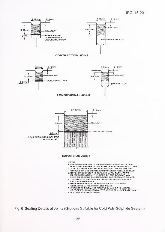
Fig. 6 Sealing Details of Joints (Grooves Suitable for Cold Poly-Sulphide Sealant)
35

IRC: 15-2011
8-10mm 3+1mm
P1 W&%k SEALAN1
5mm PAPER BACKEDCOMPRESSIBLEDEBONDING STRIP BACK-UP ROD
CONTRACTION JOINT
LONGITUDINAL JOINT
EXPANSION JOINT
NOTES:1. PAPER BACKING OF COMPRESSIBLE DEBONDING STRIP
IS NOT NECESSARY IF THE STRIP IS NON-ABSORBANT TYPE.
2. JOINTS CAN BE SEALED BY ADOPTING ONE OF THE TWOOPTIONS OF DEBONDING STRIP/BACKER-ROD AS SHOWN.
3. DEPENDING UPON THE SEALANT MANU FACTURER SRECOMMENDATION, THE SIDES OF THE GROOVE MAYHAVE TO BE SAND BLASTED/SAND PAPERED AND PRIMED.
4. THE GROOVEAND SEALANT DIMENSIONS SHOWN AREONLY FOR GUIDANCE.
5. BACKER ROD/BACK-UP ROD SHALL BE EXPANDEDCLOSED-CELL POLYETHYLENE FOAM.
6 ENDS OF THE SEALING GROOVE SHALL BE PLUGGEDBEFORE POURING SEALANT TO AVOID SPILLAGE LATERALLY.
7. ALL DIMENSION ARE IN mm.
Fig. 7 Sealing Details of Joints (Grooves Suitable for Cold Silicon Sealant)
36

IRC: 15-2011
8.3.2.2 Dowel bars as per dimensions, location and spacing shown on the drawing are
required at expansion joints to transfer wheel loads to the adjacent slab. For slabs of
thickness less than 150 mm dowel bars may not be provided (IS 6509-1972). The pre-
moulded synthetic expansion joint filler board , a compressible material shall be used to fill
the gap between adjacent slabs at expansion joint. The height of the filler board shall be
such that its top is 25 mm below the surface of the pavement. The accurate placing of
dowels at the end of the day may be achieved by means of sufficiently strong bulkheads
made of steel sections with holes drilled along the centre line to accommodate the dowel
bars in a mild steel section. The bulkhead shall be oiled or greased before placing in
position to avoid bonding with concrete. The top and bottom edges of the bulkheads and
mild steel section shall be shaped to correspond to camber of the pavements at the joint.
If considered convenient, two-piece split bulkheads may also be used. When dowel bars
are provided, bulkheads shall be designed such that they can hold the projecting ends of
the dowel bars to maintain their alignment. A box section normally is adopted for such
designs.
8.3.2.3 The bulkheads shall be securely staked in place at right angles to the centre
line and surface of the pavement with sufficient stakes to hold them in the specified position.
This may involve drilling of holes in sub-base to anchor the bulkhead with stakes.
8.3.2.4 Sealing grooves can be formed by placing wooden strips of 20-25 mm x 25 mmsections above the filler board. This can be pulled out when concrete sufficiently hardens.
For easy removal of the wooden strip without damaging the edges, the sides of the strips
may be shaped suitably.
8.3.2.5 Under no circumstances shall any concrete be left above the expansion joint
filler or across the joint at any point. Any concrete spanning the ends of the joint next to the
forms shall be carefully cut away after the forms are removed.
8.3.3 Transverse contraction joints
These shall be placed as shown on the drawing and shall be of the weakened plane of
"dummy" groove type. They shall be constructed by forming in the surface of the slab, a slot
not less than 3 mm wide and having a depth equal to one-fourth to one-third the depth of
the pavement at the thinnest part of its section. The groove is formed preferably by a joint
cutting saw. This groove is subsequently widened and sealed with sealant as shown in
Fig. 4, 5, 6 and 7. Alternatively in manual construction and minor works, the slot may be
formed in a manner approved by the Engineer-in-Charge, such as, by pushing into the
concrete a flat bar or plastic strip or the web of a "T" bar using a suitable vibratory device,
removing the bar subsequently, and keeping the slot open. It shall be ensured that no
spalling of concrete occurs wr\ile removing the bar. Such manually formed grooves are
found to affect the riding quality of the pavement.
37

IRC: 15-2011
8.3.4 Transverse constructionjoints
These shall be placed whenever placing of concrete is suspended for more than 30 minutes.
Excepting in the case of emergency, construction shall always be suspended at the regular
site of expansion or contraction joint. If the construction joint is located at the site of an
expansion joint, regular expansion joint shall be provided; if at the site of a contraction joint
or otherwise, the construction joint shall be of butt type with dowels. In case of emergency
the joint should be placed only in the middle third of the specified contraction joint interval.
At all construction joints, bulkhead shall be used to retain the concrete and care shall be
taken in striking off and finishing the surface to the top face of the bulkhead. When work is
resumed, the surface of concrete laid subsequently, shall conform to the grade and cross-
section of previously laid pavement, and a straightedge 3 m in length shall be used parallel
to the centre line, to check any deviation in the surface of the two sections. Any deviation
from the general surface, in excess of 3 mm, shall be corrected.
8.3.5 General requirements oftransversejoints
Transverse joints shall be straight within the following tolerances along the intended line of
joints which is the straight line transverse to the longitudinal axis of the carriageway at the
position proposed by the Engineer, except at road junctions or roundabouts where the
position shall be as described in the drawings :
i) Deviations of the filler board in the case of expansion joints from the
intended line of the joint shall not be greater than ±10 mm.
ii) The best fit straight line through the joint grooves as constructed shall not
be more than 25 mm from the intended line of the joint.
iii) Deviations of the joint groove from the best fit straight line of the joint shall
not be greater than 1 0 mm.
iv) Transverse joints on each side of the longitudinal joint shall be in line with
each other and of the same type and width. Transverse joints shall have a
sealing groove which shall be sealed as per Clause 8.6 and 8.7.
8.3.6 Dowel Bars
Dowel bars shall be mild steel rounds conforming to IS 432, of Grade S 240 and in
accordance with details/dimensions as indicated in the drawing and free from oil, dirt,
loose rust or scale. These shall be treated preferably by epoxy coating or any approved
anti-corrosion treatment. They shall be straight, free of irregularities and burring restricting
free movement in the concrete. The sliding ends shall be sawn or cropped cleanly with no
protrusions outside the normal diameter of the bar. The dowel bar shall be supported on
38

IRC: 15-2011
cradles/dowel chairs in pre-fabricated joint assemblies positioned prior to the construction
of the slabs or mechanically inserted by a Dowel Bar Inserter (DBI) with vibration into the
plastic concrete by a method which ensures correct placement of the bars besides full re-
compaction of the concrete around the dowel bars.
8.3.7 Design of dowel bars is discussed in IRC:58. Recommended dimensions of
dowel bars in concrete pavements are given in Table 12.
Table 12 Recommended Dimensions of Dowel Bars for Rigid
Pavements for an Axle Load of 10.2 T
Slab thickness,mm Dowel Bar Details
Diameter, mm Length, mm Spacing, mm200 25 450 300
250 32 450 300
300 38 500 300
350 38 500 300
8.3.8 Unless shown otherwise on the drawings, dowel bars shall be positioned at
mid depth of the slab within a tolerance of ±20 mm, and centred equally about intended
line of the joint within a tolerance of ±25 mm. They shall be aligned parallel to the finished
surface of the slab and to the centre line of the carriageway and to each other within
tolerances given hereunder:
1) For bars supported on cradles prior to the laying of the slab:
a) All bars in a joint shall be within ±3 mm per 300 mm length of bar.
b) 2/3rd of the bars shall be within ±2 mm per 300 mm length of bar.
c) No bar shall differ in alignment from an adjoining bar by more than
3 mm per 300 mm length of bar in either the horizontal or the vertical
plane.
d) Cradles supporting dowel bar shall not extend across the line of joint,
i.e., no steel bar of the cradle assembly shall be continuous across
the joint.
2) For all bars inserted after laying of the slab:
Twice the tolerance for alignment as indicated in 1 ) above.
Dowel bars, supported on cradles in assemblies, when subject to a load
of 110 N applied at either end and in either the vertical or horizontal
39

IRC: 15-2011
direction (upwards and downwards and both directions horizontally)
shall conform to be within the following limits :
i) Two-thirds of the number of bars of any assembly tested shall
not deflect more than 2 mm per 300 mm length of bar.
ii) The remainder of the bars in that assembly shall not deflect
more than 3 mm per 300 mm length of bar.
8.3.9 Dowel bars shall be covered by a thin plastic sheath for at least 60 percent of
the length from one end for dowel bars in contraction joints or half the length plus 50 mm for
expansion joints. The sheath shall be tough, durable and of an average thickness not greater
than 0.5 mm and shall have one closed end. The sheathed bar shall comply with the
following pull out test.
8.3.10 Four bars shall be taken at random from stock or without any special preparation
and shall be covered by sheaths as required in this Clause. The ends of the dowel bars
which have been sheathed shall be cast centrally into concrete specimens 150 x 150 x
60i l n ii s f i i ii i< !<'
c 4 the san le mixf»ropoi tions to be used! in the pavement, but with a maximum
nominal aggregate size of 31.5 mm and cured in accordance with IS 516. At 7 days a
tensile load shall be applied to achieve a movement of the bar of at least 0.25 mm . The
average bond stress to achieve this movement shall not be greater than 0. 14 M Pa.
8.3.11 For expansion joints, a closely fitting cap 1 00 mm long with closed end consisting
of Gl pipe of 3 mm thickness shall be placed over the sheathed end of each dowel bar. An
expansion space at least equal in length to the thickness of the joint filler board shall be
formed between the end of the cap and the end of the dowel bar by using compressible
sponge. To block the entry of cement slurry between dowel and cap it may be taped all
around.
8.4 Longitudinal Joints
8.4.1 General
These joints known as warping joints can be formed by two different methods: (i) They can
be of the plain butt type and shall be formed by placing the concrete against the face of the
slab concreted earlier. The face of the slab concreted earlier, shall be painted with bitumen
before placing of fresh concrete, (ii) When a pavement of width of more than one lane is
laid, the longitudinal joint may be cut by a joint cutting machine (generally with in 6-14
hours). Longitudinal joint becomes necessary to relieve warping stresses when the
pavement width exceeds 5 m.
40

IRC: 15-2011
8.4.2 Tie bars
Tie bars in longitudinal joints shall be plain mild steel bars conforming to IS 432 Part 1 or
deformed steel bars complying with IS 1786 and in accordance with the requirements
given below. The bars shall be free from oil, dirt, loose rust and scale.
8.4.3 Tie bars are used across the joints of concrete pavements wherever it is
necessary or desirable to ensure firm contact between slab faces or to prevent abutting
slabs from separating. Tie bars are not required for structural reasons, but their only function
being to prevent separation of the slabs, especially at fills or curves. Tie bars are-not
designed to act as load transfer devices. Tie bars are designed to with stand tensile stresses
only.
8.4.4 Tie bars projecting across the longitudinal joint shall be protected from corrosion
for 75 mm on each side of the joint by a protective coating of bituminous paint with the
approval of the Engineer. The coating shall be dry when the tie bars are used.
8.4.5 Tie bars shall be laid automatically in a fully mechanised construction using slip
form paving as being followed these days for most rigid pavement construction. For semi
mechanised construction tie bars in longitudinal joints shall be made up into rigid
assemblies with adequate supports and fixings to remain firmly in position during the
construction of the slab. Alternatively, tie bars at longitudinal joints may be mechanically or
manually inserted into the plastic concrete from above by vibration using a method which
ensures correct placement of the bars and re-compaction of the concrete around the tie
bars (tie bar inserter). When the pavement is constructed in single lane width, tie rods are
also inserted mechanically or manually from sides. During side insertion in fixed form
paving these may be bent so that half length remains along the form. After removal of
forms, bars shall be straightened using hollow Gl pipe so that they extend into the concrete
placed on the other half of the concrete slab.
8.4.6 Tie bars shall be positioned to remain within the upper middle third of the slab
depth as indicated in the drawings approximately parallel to the surface and approximately
perpendicular to the line of the joint, with the centre of each bar on the intended line of the
joints within a tolerance of + 50 mm, and with a minimum cover of 30 mm below the joint
groove. Table 13 gives typical sizes of tie bars used in concrete slabs.
8.5 Arrangement of Different Types of Joints
8.5.1 For more details about arrangement of the different types of joints, IRC:57 maybe referred. The joint spacing at curve portion may be reduced by 20-30 percent. In general,
slab configuration is considered as 3.5 m x 5.0 m.
41

IRC: 15-2011
Table 13 Details of Tie Bars for Longitudinal Joints of Two-Lane
Rigid Pavements (Same as IRC:58)
Slab Tie Bar Details
Thickness Diameter Max. Spacing (mm) Minimum Length (mm)(mm) (d) Plain Deformed Plain Bars Deformed
(mm) Bars Bars Bars
1I ou 8 330 530 440 480
10 520 830 510 560
10 390 620 510 560
12 560 900 580 640
250 12 450 720 580 640
300 12 370 600 580 640
16 660 1060 720 800
350 12 320 510 580 640
16 570 910 720 800
Note:
1 ) The recommended details are based on the following values of different design
parameters for a slab configuration of 3.5 m x 5.0 m.
2) S=125 MPa for plain bars, 200 MPa for deformed bars, Bond stress for plain
bars = 1.75 MPa, for deformed bars = 2.46 MPa, W =24 Kg/sqm/cm of slab.
3) Where S is minimum tensile strength of steel, B is minimum bond strength of
concrete with steel bar, W is the weight of concrete/sq cm/cm.
8.5 Arrangement of Different Types of Joints
8.5.1 For more details about arrangement of the different types of joints, IRC:57 maybe referred. The joint spacing at curve portion may be reduced by 20-30 percent. In general,
slab configuration is considered as 3.5 m x 5.0 m.
8.5.2 Anchor beam and terminal slab adjoining bridge structures
Cement concrete slab will expand during hot season and this will result in the building up
of horizontal thrust on adjoining bridge structure. To contain this thrust RCC anchor beams
or approach slab are to be provided in the terminal slab. The terminal slab also needs to
be provided with reinforcement to strengthen it. A typical arrangement of anchor beamand the terminal slab are shown in Fig.8. In case of culverts, etc. where the concrete slabs
are provided above the superstructure, there is no need to construct anchor beam/approach
slab and terminal slab. In case the concrete slab abuts with culvert structure, the construction
of anchor beam/approach slab and terminal slab will be necessary.
42

IRC: 15-2011
-EXPANSION JOINTr\2mm* © 150 C/C MESH
'RST CONSTRUCTION JOINT
r APPROACH SLABSpF THE BRIDGE
I2mm» 150 C/C MESH
/BED CONCRETEi-M-15 GRADE.150 THICK
'SUBGRADE BEAM"M-15 GRAOE
ANCHOR BEAU.M-35 GRADE
BED CONCRETE.M-15 GRAOE
/tmv LEAN CONCRETEiM-15 GRADE CONCRETE.'50 THICK
M6mm* O 300 C/C
I6mm« © 300 C/C
16mm*-6Nos.
NOTE' 1) All dimension are in mm.
2) Only typical reinforcement
details have been shown in
the figure.
8.6
Fig. 8 Details ofAnchor Beam and Terminal Slab
Preparation of Joint Grooves for Sealing
8.6.1 Joint grooves usually are not constructed in the first instance to provide the
maximum width specified in the drawings when saw cut joints are adopted. They shall be
widened subsequently by sawing before sealing. Depth/width gauges shall be used to
control the dimensions of the groove during widening process.
8.6.2 If rough arises develop when grooves are made, they shall be ground to provide
a chamfer approximately 5 mm wide. If the groove is at an angle upto 10° from the
perpendicular to the surface, the over-hanging edge of the sealing groove shall be sawn
or ground perpendicular. If spalling occurs or the angle of the former is greater than 1 0°,
the joint sealing groove shall be sawn wider and perpendicular to the surface to encompass
the defects upto a maximum width including any chamfer, of 25 mm for transverse joints
and 1 5 mm for longitudinaljoints. If the spalling cannot be so eliminated then the arises
shall be repaired by an approved thin bonded arises repair, using cementitious materials,
like, epoxy or polymer concrete.
8.6.3 All grooves shall be cleaned of any dirt or loose material by air blasting with
filtered, oil-free compressed air. If need arises, the Engineer may instruct cleaning by
pressurized water jets. Depending upon the requirement of the sealant manufacturer, the
sides of the grooves may have to be sand blasted to increase the bondage between
sealant and concrete.
8.6.4 The groove shall be cleaned and dried at the time of priming and sealing.
43

IRC: 15-2011
8.6.5 Before sealing, the temporary seal inserted before subsequent widening for
blocking the ingress of dirt, soil etc. shall be removed. A highly compressible heat resistant
paper-backed debonding strip as per drawing/IRC:57 shall be inserted in the groove to
serve the purpose of breaking the bond between sealant and the bottom of the groove and
to plug the joint groove so that the sealant may not leak through to the crack below. The
width of debonding strip shall be more than the joint groove width so that it is held tightly in
the groove. In the case of longitudinal joints, heat resistant tapes may be inserted to block
the leakage through bottom of the joint.
8.7 Sealing with Sealants
8.7.1 When sealants are applied an appropriate primer shall also be used if
recommended by the manufacturer and it shall be applied in accordance with the
recommendation of the manufacturer. The sealant shall be applied within the minimum
and maximum drying times of the primer recommended by the manufacturer. Priming and
.ealing with app 3d sealants shall not be carried out when the naturally occurring
temperature in the joint groove to be sealed is below 7°C.
8.7.2 If hot applied sealant is used, it shall be heated and applied (after using raker)
from melter and pourer as shown in Fig. 9,10 and 11 . Hot sealants shall be rubberized
bitumen type. For large road projects, sealant shall be applied with extruder having flexible
hose and nozzle. The sealant shall not be heated to a temperature higher than the safe
heating temperature, as specified by the manufacturer. The dispenser shall be cleaned
out at the end of each day in accordance with the manufacturer's recommendations and
reheated material shall not be used.
12
J -: -- r~ SEE
ELEVATION SIDE VIEW
12 55 12
PLAN
Fig. 9 Details of Raker
44

IRC: 15-2011
PLAN
nE 0 Mff.S ::n-i .%HF IN'OICATlVf ONLY
Fig. 10 Schematic View of a Sealant Melter
45

IRC: 15-2011
HANDLE WOUND WITHJUTE ROPE
Fig. 1 1 A Pouring Cattle for Hot Poured Sealant
8.7.3 Cold applied sealants with chemical formulation, like, polysulphide/silicone/
polyurethane or other similar formulation may be used as per IRC:57. These shall be mixed
and applied within the time limit specified by the manufacturer. If primers are recommended
they shall be applied neatly with an appropriate brush after cleaning the grooves/cut portion
with compressed air. The MovementAccommodation Factor (MAF) shall be +/- 10 percent
for bituminous sealant, +/-25 percent for poly sulphide sealant and the MAF of silicon
sealants shall be in the range of -50 percent +100 percent. Silicon sealant can be
compressed to its 50 percent size whereas it can be stretched to +100 percent without
any change in the volume of sealant.
8.7.4 MovementAccommodation Factor (MAF) is defined as:
= (-) (Compressed Width - Original Width) X 1 00
Original Width
= (+) (Expanded Width - Original Width) X 1 00
Original Width
8.7.5 The groove configuration is different for poly-sulphide and Silicone/polyurethane.
Silicone, a single chemical formula, hardens by absorbing moisture from the air and hence
it should be placed in a thinner layer vis-a-vis primer based poly-sulphide. Accordingly, the
depth/width ratio of grooves should be modified. Besides the curing time of silicone is
more than that of poly-sulphide.
46

IRC: 15-2011
8.7.6 The sealants applied at contraction phase of the slabs would result in bulging of
the sealant over and above the slab. The right temperature and time for applying the sealant
shall be determined first. Thermometer shall be installed on a pole in the site for facilitating
control during the sealing operation.
8.7.7 Sealant shall be applied, slightly to a lower level than the slab with a tolerance
of 3±1 mm.
8.7.8 During sealing operation, it shall be seen that no air bubbles are introduced in
the sealant either by vapours or by the sealing process.
8.7.9 Reformed sealing strips of neoprene are also used for sealing joints. The strips
made of hollow section are kept pressed during insertion. Thus the strip is always under
compression and does not allow any moisture ingress in the joint groove. This technique
also will require primer.
Fig. 9 to 11 show the appliances used for joint sealing as per IRC:57 and IRC:43.
9 STORAGE OF MATERIALS AND PREPARATION FORCONSTRUCTION
9.1 General
A systems approach may be adopted for construction of the pavement, and the Method
Statement for carrying out the work, detailing all the activities including indication of
time-cycle equipment, personnel, etc. These shall be got approved from the Engineer
before the commencement of the work. The above shall include the type, capacity and
make of the batching and mixing plant besides the hauling arrangement so that the paving
can progress without any stoppage. During planning stage, it should be noted that
constructing multi-lane pavement is better than constructing single lane at a time from the
point of view of riding quality. Therefore, the capacity of plants should be planned accordingly.
9.2 Storage and Handling of Cement
9.2.1 The requirement of cement being of a very high order; cement is normally stored
in large capacity vertical silos. Cement is carted in bulk to feed the storage silos. In the
case of small projects involving manual or semi-mechanised paving, cement in bags maybe used.
9.2.2 Supply of cement should be co-ordinated with its consumption so that it is not
stored right through the rainy season, when normally concreting is discontinued. Cementhaving lumps which have been caused due to improper storage or by pressure due to
47

IRC: 15-2011
over-loading of bags shall not be considered for use unless these lumps can be easily
powdered with pressure between fingers. Before such cement is used, representative
sample containing the lumps in fair proportion also shall be taken and tested to fulfil the
minimum requirements.
9.2.3 Owing to the slightly deliquescent nature of rapid hardening cement and
53 grade cement, special care should be taken in its storage and in any case, it should not
be stored for longer than three months.
9.3 Storage and Handling of Aggregates
9.3.1 The location and preparation of sites, minimum size of stack and the methods
adopted for dumping and stacking to prevent segregation of coarse and fine material
shall be subjected to the approval of the Engineer. Aggregates stock piles may be made
on ground that is denuded of vegetation, levelled, compacted with good quality soil sub-
base material and well drained. Aggregates from different sources and/or of different
grading shall not be stacked together. Each separate size of coarse aggregate shall be
stacked separately and separate wooden or steel partition shall be provided to avoid
intermixing. The storing of aggregates upon the carriageway or shoulders shall not be
permitted.
9.3.2 If aggregates are stored in conical stacks, segregation will be increased by the
rolling of the coarser particles down the sides of the stacks. To avoid this, stacks should
be built up in approximately horizontal layers. Dry fine aggregate get blown away easily; it
may be helpful to moisten the aggregates which shall be stacked in small heaps either on
the ground or in the vehicles to avoid segregation of aggregates
9.3.3 Sufficient quantity of aggregates should be crushed in advance so that there is
adequate supply of matching aggregates available in the site. Stock piling aggregates for
use beyond 2-3 months should be done cautiously as it is likely to be contaminated with
foreign matter.
9.3.4 The aggregates shall be handled from the stacks and fed into the mixer in such
a manner as to secure the stipulated grading of the material. Aggregates that have becomemixed with earth or other foreign material shall not be used. They shall be washed clean
before use. The aggregates contaminated with fine dust, etc. are normally screened with
a mobile screening plant before use.
9.4 Batching of Materials
9.4.1 All batching of materials shall be by weight. After determining the proportion of
ingredients for the field mix, the fine aggregate and each separated size of coarse aggregateshall be proportioned by weight in an approved weigh-batching plant and placed into the
hopper of the mixer along with the necessary quantity of cement.
48

IRC: 15-2011
9.4.2 Cement shall be measured either by weight or by the bag as packed by the
manufacturer. Where cement is measured by the bag, it would be necessary to sample-
check the weight ofthe bags occasionally. All materials other than cement shall be calculated
on the basis of one or more whole bags of cement taking the weight of cement as
1440 kg/cu.m. Water may be measured by volume. Where it is unavoidable, volume
batching of aggregates may be permitted as a special case in small projects.
10 CONSTRUCTION
10.1 Fully Mechanised Construction
10.1.1 General
The batching plant shall include minimum four bins, weighing hoppers, and scales for the
fine aggregate and for each size of coarse aggregate. If cement is used in bulk, a separate
scale for cement shall be included. The weighing hoppers shall be properly sealed and
vented to preclude dust during operation. Approved safety devices shall be provided and
maintained for the protection of all personnel engaged in plant operation, inspection and
testing. The batch plant shall be equipped with a suitable non-resettable batch counter
which will correctly indicate the number of batches proportioned
1 0.1 .2 Bins and hoppers
Bins with minimum four numbers ofadequate separate compartments shall be provided in the
batching plant. In addition, we may have another bin for any mineral admixture if used.
10.1.3 Automatic weighing devices
Batching plant shall be equipped to proportion aggregates and bulk cement by means of
automatic weighing devices using load cells.
The batching plant shall have facility for injecting at least two admixtures in the mixing pan.
The discharging mechanism shall have appropriate chutes, down pipes, etc. so that the
discharged mix will not get segregated.
10.1.4 Control cabin
An air-conditioned centralised control cabin shall be provided for automatic operation of
the equipment.
10.1.5. Batching by weight only is recommended. However, if batching by volume is
permitted, as a special case, separate measuring boxes shall be provided for the different
49

IRC: 15-2011
aggregates. The boxes shall be of strong construction provided with handles for convenient
lifting and loading into the mixer. They shall be of such size that it should be possible to
measure out the requisite quantity and capable of being lifted by two men. Each box shall
be provided with a straight edge of required length for striking off after filling. If so directed
by the Engineer, improved facilities, such as, tipping boxes of accurate capacity working
on run-out rails arranged for direct delivery into the hopper of the mixer shall be provided
by the construction agency. In volume batching, suitable allowance shall be made for the
bulking of fine aggregate due to the presence of water. For this purpose, the bulking shall
be determined as per relevant Indian Standard Specification.
10.1 .6 The location of the batching plant is an important issue to be looked into while
planning the project. As there is a limitation on using the concrete mix after adding the
water within a stipulated time, the mix shall not normally be carried beyond 1 5 km of lead
on a maintained road not requiring more than 40 minutes of travel time. Therefore, the
location of the batching plant in a road project has to be decided carefully.
10.1.7 Mixers
Mixers shall fre pan type, reversible type with single or twin shaft or any other mixer capable
of combining the aggregates, cement, water and admixtures into a thoroughly mixed and
uniform mass within the specific mixing period, and of discharging the mixture, without
segregation. In twin shaft mixer, mixing time is normally very low (about 6 cubic materials
may be mixed in 20-30 seconds). Facility i.e hydrometers for the measurement of the
density of the admixtures shall be available at site. Each stationary mixer shall be equipped
with an approved timing device which will automatically lock the discharge lever when the
drum has been charged and release it at the end of the mixing period. The device shall be
equipped with a bell or other suitable warning device adjusted to give a clearly audible
signal each time the lock is released. In case of failure of the timing device, the mixer maybe used for the balance of the day while it is being repaired, provided that each batch is
mixed for 90 seconds or as per the manufacturer's recommendation. The mixer shall be
equipped with a suitable non-resettable batch counter which shall correctly indicate the
number of batches mixed.
The mixers shall be cleaned at suitable intervals. The pick up and throw-over blades in the
drum or drums shall be repaired or replaced when they are worn down 20 mm or more.
The Contractor shall (1) have at the job site a copy of the manufacturer's design, showing
dimensions and arrangements of blades in reference to original height and depth, or (2)
provide permanent marks on blade to show points of 20 mm wear from new conditions.
Drilled holes of 5 mm diameter near each end and at midpoint of each blade are
recommended. Batching plant shall be calibrated for the each ingredients up to its maximumquantity being used in the mix at site in the beginning and thereafter at suitable interval not
exceeding 1 month.
50

IRC: 15-2011
10.1.8 Mixing
10.1.8.1 General
The mixing of concrete shall be done in a plant which will ensure a uniform distribution of
materials throughout the mass so that the mix is uniform in colour and homogeneous. All
concrete shall be mixed in quantities for immediate use.
10. 1.8.2 The mixer shall be equipped with an approved water measuring device capable
of accurate measurement of water required per batch. The mixer shall preferably be
equipped with a mechanically operated pump for filling the mixer tank.
10. 1.8.3 The mixer shall normally be equipped with an approved timing device which will
automatically lock the discharge lever during the full time of mixing and release it at the
end of the mixing period; the device shall also be equipped with a bell, adjusted to ring
each time the lock is released. If the timing device gets broken or out of order, the mixer
will be permitted to be used while the same is being repaired, provided an approved
time-piece equipped with minute and second hands is provided. Each batch shall be
mixed for at least one and a half minutes or as recommended by the plant manufacturer.
10.1.8.4 Spilling of the materials at either end of the mixer shall be corrected by reducing
the size of the batch and in no case shall the volume of the mixed material per batch
exceed the manufacturer's guaranteed capacity of the mixer. The type, size and number of
mixers shall be so chosen as to provide the required output without overloading.
10.1.8.5 The mixing speed of the drum shall not be less than 1 5 revolutions per minute
nor the peripheral speed of the drum greater than 60 m per minute.
10. 1.8.6 The sequence of loading shall be coarse aggregates, fine aggregates, cement,
fly ash if used. After dry mixing, water will be released from venturi-meter. The plasticizer
mixed with the recommended pecentage of water shall be added in the last. The quantitities
are programmed in the computer accordingly.
10.1.8.7 The skip shall be so maintained and operated that each batch will be completely
discharged into the mixing drum at the loading of the mixer. The mixer shall be cleaned at
suitable intervals while in use.
10.1.9 Time of mixing
The mixing of each batch will continue generally not less than one and half minutes, after all
the materials are discharged into the mixer or as recommended by the manufacturer of
the plant and to the satisfaction of the Engineer.
51

IRC: 15-2011
10.1.10 Retempering
The retempering of concrete, i.e., remixing with or without additional cement, aggregate
or water shall not be permitted.
10.1.11 Hauling of concrete
Freshly mixed concrete from the central batching and mixing plant shall be transported to
the paver site by means of trucks/tippers or transit mixers of sufficient capacity and
approved design in sufficient numbers to ensure a constant supply of concrete. Tarpaulin
covers shall be used for protection of concrete against the weather. The tipper trucks shall
be capable of maintaining the mixed concrete in a homogeneous state and discharging
the same without segregation and loss of cement slurry. The feeding to the paver, when
used, is to be regulated in such a way that the paving is done in an uninterrupted manner
with a uniform speed throughout the days work. For semi-mechanised jobs, concrete can
be transported in pans as head loads or in small wheel barrows.
10.1.12 Placing of concrete
Concrete mixed in central mixing plant shall be transported to the site without delay and
the concrete which has been mixed too long before laying will be rejected and shall be
removed from the site. The total time taken from the add ition of the water to the mix, until
the completion of the surface finishing and texturing shall not exceed 120 minutes when
concrete temperature is less than 25°C and 1 00 minutes when the concrete temperature
is between 25°C to 30°C. Trucks/Tippers delivering concrete shall not run directly on plastic
sheet nor shall they run on completed slabs until after 28 days of placing of concrete.
10.1.13 Equipment
The concrete shall be placed with an approved fixed form or slip form paver with independent
units designed to (i) spread, (ii) consolidate from the mould, screed and float-finish,
(iii) texture and cure the freshly placed concrete in one complete pass of the machine in
such a manner that a minimum of hand finishing will be necessary and so as to provide a
dense and homogeneous pavement in conformity with the plans and Specifications.
The paver shall be equipped with electronic sensors to pave the slab to the required
thickness, camber and alignment in the case of slip form pavers.
Vibrators shall operate at a frequency and spacing recommended by the manufacturer.
The variable vibration setting shall be provided in the machine.
The placement of dowels can be done by either using Dowel Bar Inserter (DBI) or by
prefixing the dowels on steel chairs to the sub-base. The DBI is normally fitted in the paver
finisher. The progress of work is better when a DBI is employed
52

IRC: 15-2011
10.1,14 Use ofguidewires
10.1.14 1 Where slip form paving is proposed, a guidewire shall be provided along both
sides of the slab. Each guidewire shall be at a constant height above and parallel to the
required edges of the slab as described in the contract/drawing within a vertical tolerance
of ±2 mm. Additionally, one of the wires shall be kept at a constant horizontal distance
from the required edge of the pavement as indicated in the contract drawings within a
lateral tolerance of ±1 0 mm
10.1 14.2 The guidewires shall be supported on stakes not more than 6 m apart by
connectors capable of fine horizontal and vertical adjustment. The stake to stake distance
in case of paving at curve shall suitably be decreased. The guidewire shall be tensioned
on the stakes so that a 500 gram weight shall produce a deflection of not more than
20 mm when suspended at the mid point between any pair of stakes. The ends of the
guidewires shall be anchored to fixing point or winch and not on the stakes.
10.1.14.3 The stakes shall be positioned and the connectors maintained at their correct
height and alignment 12 hours on the day before concreting takes place until 12 hours
after finishing of the concrete. The guidewires shall be checked and tensioned on the
connectors at any section at least 2 hours before concreting that section.
10.1.14.4 The Engineer shall inspect and approve the line and level, the stakes and
connectors which are ready for use in the length of road to be constructed at least 12 hours
before the day of construction of slab. Any deficiencies noted by the Engineer shall be
rectified. Engineer shall check the level before the commencement of work. Work shall not
proceed until the Engineer has given his approval. It shall be ensured that the stakes and
guidewires are not affected by the construction equipment when concreting is in progress.
Arrangements should be readily available to correct it in case the string line is inadvertently
disturbed.
10.1.15 Construction by slip form paver
10.1.15.1 The slip form paving train shall consist of power machine which spreads,
compacts and finishes the concrete in a continuous operation. The slip form paving machine
shall compact the concrete by internal vibration and shape it between the side forms with
either a conforming plate or by vibrating and oscillating finishing beams. The concrete
shall be deposited without segregation in front of slip form paver across the whole width
and to a height which at all times is in excess of the required surcharge. The deposited
concrete shall be struck off to the necessary average and differential surcharge by meansof the strike off plate or a screw auger device extending across the whole width of the slab.
The equipment for striking off the concrete shall be capable of being rapidly adjusted for
changes of the average and differential surcharge necessitated by change in slab thickness
or cross fall.
53

IRC: 15-2011
10.1.15.2 The level of the conforming plate and finishing beams shall be controlled
automatically from the guidewires installed as per Clause 10.1 .13 by sensors attached at
the four corners ofthe slip form paving machine. The alignment of the paver shall be controlled
automatically from the guidewire by at least one set of sensors attached to the paver. The
alignment and level of ancillary machines for finishing, texturing and curing of the concrete
shall be automatically controlled relative to the guidewire or to the surface and edge of an
adjoining hardened slab.
10.1.15.3 Slip form paving machines shall have vibrators of variable output, with a
maximum energy output of not less than 2.5 KW per metre width of slab per 300 mm depth
of slab for a laying speed upto 1 .5 m per minute or pro-rata for higher speeds. The machines
shall be of sufficient mass to provide adequate reaction during spreading and paving
operations on the traction units to maintain forward movements during the placing of
concrete in all situations.
10. 1. 15.4 If the edges of the slip formed slab slump to the extent that the surface of the
top edge ofthe slab does not comply with the requirements then special measures approved
by the Engineer shall be taken to support the edges to the required levels and work shall
be stopped until such time as the Contractor can demonstrate his ability to slip form the
edges to the required levels. The slumped edge shall have to be corrected by adding
fresh concrete after roughening the surface.
10. 1. 15.5 The pace of construction of slabs shall desirably not be less than 1 m per minute.
The capacity or the batching plant should be sufficiently more than this requirement so that
the paver remains in motion without stoppages for want of mix. This factor is essential for
achieving better riding quality.
10.1.16 Surface texture
10.1.16.1 Tining
After final floating and finishing of the slab and before application of the liquid curing
membrane preferably two coats, the surface of concrete slabs shall be textured either
in the transverse direction (i.e., at right angles to the longitudinal axis of the road) or in
longitudinal direction (i.e., parallel to the centerline of the roadway). The texturing shall
be done by tining the finished concrete surface by using rectangular steel tines.
A beam or a bridge mounted with steel tines shall be equipped and operated with
automatic sensing and control devices from main paver or auxiliary unit. The tining
unit shall have facility for adjustment of the downward pressure on the tines as necessary
to produce the desired finish. The tining rakes shall be cleaned often to remove snots
of slurry. The tines will be inspected daily and all the damaged and bent tines shall be
54

IRC: 15-2011
replaced before commencing texturing. Tined grooves shall be 3 mm wide and
3 to 4 mm deep. Before commencing texturing, the bleeding water, if any, shall be removed
and texturing shall be done on a firm surface. Normally, transverse tinning will be preferred.
a) Transverse Tining: When the texturing is specified in transverse direction, a
beam of at least 3 m length mounted with tines shall be moved in transverse direction to
produce the texture. The grooves produced shall be at random spacing but uniform in
width and depth. The spacing shall conform to a pattern shown below:
Random spacing in mm
10 14 16 11 10 13 15 16 11 10 21 13 10
The above pattern shall be repeated. Texturing shall be done at the right time such that the
grooves after forming shall not close and they shall not get roughened. Swerving of groove
patterns will not be permitted. The completed textured surface shall be uniform in
appearance. The texture depth shall be measured with gauge and Vernier Calliper (simple/
digital)
b) Longitudinal Tining: Longitudinal tinning shall be done, if specified in the
Contract. The texturing bridge shall be wide enough to cover the entire width of the
carriageway but within 75 mm from the pavement edge. The centre to centre spacing
between the tines shall be 18 to 21 mm. The width of tine texture shall be 3 mm and depth
shall be 3 to 4 mm. The texture depth shall be measured with gauge and Vernier Calliper
(simple/digital)
10.1.16.2 Brush texturing
Alternatively on the instructions of the Engineer, the brush texturing may be applied. The
brushed surface texture shall be applied evenly across the slab in one direction by the use
of a wire brush not less than 450 mm wide but wider brushes normally of 3 m length are
preferred. The brush shall be made of 32 gauge tape wires grouped together in tufts placed
at 10 mm centres. The tufts shall contain an average of 14 wires and initially be 100 mmlong. The brush shall have two rows of tufts. The rows shall be 20 mm apart and the tufts in
one row shall be opposite the centre of the gap between tufts in the other row. The brush
shall be replaced when the shortest tuft wears down to 90 mm length.
The texture depth shall be determined by the Sand Patch Test. This test shall be performed
at least once for each day's paving and wherever the Engineer considers it necessary at
times after construction as under:
Five individual measurements of the texture depth shall be taken at least 2 m apart anywhere
along a diagonal line across a lane width between points 50 m apart along the pavement.
55

IRC: 15-2011
No measurement shall be taken within 300 mm of the longitudinal edges of a concrete
slab constructed in one pass. After the application of the brushed texture, the surface of
the slab shall have a uniform appearance.
Texture depths shall not be less than the minimum required when measurements are taken
as given in Table 14 nor greater than a maximum average of 1 .25 mm.
Table 14 Texture Depth
SI.
No.
Time of Specified Tolerance Number of Test
Measurements
Texture Depth(mm) Required
1) Between 24 hours and 7 days after
the construction of the slab or until
the slab is first used by vehicles.
An average of
5 measurements1.00 ±0.25
2) Not later than 6 weeks but before
the road is opened to public traffic.
An average of
5 measurements1.00 +0.25
-0.35
Where the texture depth requirements are found to be deficient, the Contractor shall make
good the texture across the full lane width over length as directed by the Engineer, by
retexturing the hardened concrete surface in an approved manner.
The edges of the concrete slabs shall be rounded after texturing using an arising tool
having a radius of 3 mm diligently without applying pressure to the surface to leave the
pavement edges smooth and true to line.
Measurement of texture depth-sand patch method: The following apparatus shall be used:
1 ) A cylindrical container of 25 ml internal capacity.
2) A flat wooden disc 64 mm diameter with a hard rubber disc. 1 .5 mm thick,
struck to one face, the reverse face being provided with a handle.
3) Dry natural sand with a rounded particle shape passing a 300 micron
IS sieve and retained on a 1 50 micron IS sieve.
The surface to be measured shall be dried, any extraneous mortar and loose material
removed and the surface swept clean using a wire brush both at right angles and parallel
to the carriageway. The cylindrical container shall be filled with the sand, tapping the base
3 times on the surface to ensure compaction, and striking off the sand level with the top of
the cylinder. The sand shall be poured into a heap on the surface to be treated. The sandshall be spread over the pavement surface, working the disc with its face kept flat in a
circular motion so that the sand is spread into a circular patch with the surface depressions
filled with sand to the level of peaks.
56

IRC: 15-2011
The diameter of the patch shall be measured to the nearest 5 mm. The texture depth of
concrete surface shall be calculated from 31000/(DxD) mm where D is the diameter of the
patch in mm.
1 0.1 .17 Measurement of texture depth by Vernier Calliper method
In case of texturing by fining, the texture depth may be measured by gauge and Vernier
Calliper/digital vernier calliper.
10.2 Semi-Mechanised and Labour-Oriented Construction Technique
10.2.1 General
Use of very sophisticated paving machines and high capacity concrete batch mixer may
not be possible in small concrete road projects and also in remote hilly terrains or near
bridge structures, although with the use of such machines and plants the end product is
always of better quality. Without these advanced equipments concrete roads can be
constructed using semi-mechanised and labour-oriented constructions but the resulting
quality and surface may not be the same as achieved with mechanised constructions.
10.2.2 Forms
In large sized projects, it is common to use slip form paving technique where no side
forms are necessary to retain the shape of green concrete slab. The fixed-forms made of
steel channels or fabricated steel sections are generally made use of. Wooden forms,
although, can be used, are liable to get damaged after each usage. Therefore, wooden
forms are to be considered as a last resort.
10.2.3 Steel forms
All side forms shall be of mild steel unless use ofwooden section is specially permitted by
the Engineer. The steel forms shall be mild steel channel sections of depth equal to the
thickness of the pavement or a few millimetres less than the thickness of the pavement to
match with the plus level tolerances specified for sub-base. In the latter case, the forms
shall be levelled by using metal wedges or shims. The thickness of flange and web shall
not be less than 6 mm and shall be capable of resisting all loads applied in the paving
process. The length of form shall not be less than 3 m except in the case of installations
along curves.
10.2.4 The sections shall have a length of at least 3 m except on curves of less than
45 m radius, where shorter sections may be used. When set to grade and staked in place,
the maximum deviation of the top surface of any section from a straight line shall not exceed
57

IRC: 15-2011
2 mm in the vertical plane and 5 mm in the horizontal plane. The method of connection
between sections shall be such that the joint formed shall be free from difference in level,
play or movement in any direction. The use of bent, twisted or worn-out forms will not be
permitted. At least three stake pickets for each 3 m of form and the bracing and support
must be ample to prevent springing of the forms under the pressure of concrete or the
weight or thrust of machinery operating on the forms.
10.2.5 The supply of forms shall be sufficient to permit their remaining in place for
12 hours after the concrete has been placed. Any unevenness in the form work particularly
the top will affect riding quality.
10.2.6 Wooden forms
Wooden forms may be used only when specifically permitted in the drawing with the
exception that their use is herein approved for all curves having radii of less than 45 m,
wooden forms shall be dressed and planed on the inside face. They shall have minimum
base width of 100 mm for slab thickness upto 200 mm and a minimum base width of
1 50 mm for slabs over 200 mm thick. Their depth shall be equal or slightly less than the
thickness of the pavement but it would be made up by metal shims. These forms when
used on straights shall have a minimum length of 3 m. Forms shall be held by stakes set at
intervals not exceeding 2 m. Two stakes, one on each side, shall be placed at each joint.
The forms shall be firmly nailed or secured to the side stakes, and securely braced at
joints, where necessary, so that no movement will result from the pressure of the concrete
or the impact of the tamper and during finishing work. Wooden forms shall be capped
along the inside upper edge with 50 mm angle iron, well recessed and kept flush with the
face of the wooden forms. The maximum deviation of the top surface of any section from
a straight line shall not exceed the stipulations laid.
10.2.7 Setting of forms
The forms shall be jointed neatly and shall be set with exactness to be required grade and
alignment. Both before and after the forms are placed and set, the subgrade or sub-base
under the forms shall be thoroughly tamped in an approved manner. Sufficient rigidity shall
be obtained to support the forms in such a position that during the entire operation of
compacting and finishing of concrete they shall not at any time deviate more than 3 mmfrom a straight edge 3 m in length. Forms which show a variation from the required rigidity
or alignment and levels shown in the drawing, shall be reset or removed, as directed.
The length and number of stakes shall be such as to maintain the forms at the correct line
and grade. All forms shall be cleaned and oiled each time before they are used. Formsshall be set ahead of the actual placing of concrete for the entire day's work.
58

IRC: 15-2011
1 0.2.8 Placement of steel
In placing reinforcing steel, the initial layer of concrete shall be struck off to the entire width
of the slabs and of sufficient length to permit sheet or mat of reinforcement to be laid full
length without further manipulations ofthe reinforcement. Displacement of the reinforcement
during concreting operations shall be prevented.
10.2.9 Dowels
Transverse joints shall be provided with dowels and of the dimension and at the spacing
and location indicated on the drawing. They shall be firmly supported in place, accurately
aligned parallel to the subgrade/sub-base, parallel to each other and parallel to the centre
line of the pavement, by means of appropriate dowel supports/chairs.
10.2.10 Tie bars
Tie bars are provided in longitudinal joints to prevent opening of such joints and shall be
bonded to the adjacent slabs on both sides of the longitudinal joint. These are installed by
providing appropriate chair or these are installed by providing appropriate (drilled) holes
in the side forms depending on the size and spacing of bars. These are sometimes bent
aside temporarily to avoid obstruction to construction traffic and straightened later at the
time of laying of slab in the adjacent lane.
10.2.11 Plants equipments and tools
The requirements of concrete quality in road construction being large which again is to be
supplied continuously, the mixes are normally to be produced from mixers. The plants and
equipments considered essential in semi-mechanized and labour-oriented construction
are :-
i) A couple of tilting type drums mixers of at least 0.2 cu.m capacity.
The number of mixers to be employed in a project shall be decided
on the basis of the size of the project.
ii) Vibrating screeds for tamping and compacting pavement surface.
These are moved on the levelled fixed forms or side forms to achieve
the required smoothness, grade and surface regularity.
iii) A couple of needle vibrators. Alternatively fixed pavers fitted with
vibrators and finisher can also be used.
iv) Concrete-saw: This is required for forming contraction joints in a
continuously constructed lane.
59

IRC: 15-2011
v) Hand held sprayer for applying liquid curing compound at least
1 0-20 kg capacity container/tank.
vi) Texturing brooms
vii) Straight edges of 3 m length.
viii) Appropriate tools for sealing joints.
ix) Fixed side forms measuring at least 1 00-1 50 m length.
x) Stop-end and start-end made of steel or wooden sections or bulk
These gadgets are required for commencing and stopping
the paving activity
1 0.2.1 2 Hauling of mix
Transporting of concrete mix from mixer to paving site with steel pans is not permitted in
major works. However, these can be permitted in small size works only with the written
permission of the Engineer. The mix tends to get segregated during such handling. It is
desirable to use wheel-barrows or trolleys for carrying mix to the paving site. The workability
of the mix can be controlled better with the use of wheel-barrows.
1 0.2. 1 3 Placing of concrete
Where semi-mechanised construction technique is adopted, concrete shall be deposited
between the forms directly from head loads or wheel barrows. Where a certain amount of
redistribution is necessary, it shall be done with shovels and not with rakes. The concrete
shall be compacted with needle vibrators and vibrating screeds in semi-mechanised
construction where a paver finisher is not available. Use of vibrator near side forms is
essential to eliminate honey combing. To effect adequate compaction, the concrete shall
be placed with appropriate surcharge over the final slab thickness. The amount of surcharge
will depend on the mode of placement of concrete and shall be determined by trial. In
general, the required surcharge is about 20 percent of the required slab thickness. Any
portion of the batch of concrete that becomes segregated while depositing it on subgrade/
sub-base shall be thoroughly mixed with the main body of the batch during the process of
spreading. In case of unavoidable interruption, a full depth transverse joint shall be madeat the point of stoppage of work provided the section on which the work has been
suspended is about 2 to 3 m long.
10.2.14 Compaction
Where semi-mechanized and labour-oriented technique is adopted, compaction of the
pavement shall be accomplished by a vibrating screed supplemented by plate/internal
vibrators. For slabs of thickness more than 125 mm, vibrating screeds may be supplemented
by portable needle vibrators. The vibrating screed shall rest on side forms. It shall be
60

IRC: 15-2011
lowered vertically on to the concrete surface, evenly spread to the appropriate level above
the base to provide the required surcharge for compaction; allowed to remain in position
for a few seconds until compaction is complete, then lifted vertically and lowered to the
adjacent strip of uncompacted concrete. The amplitude of vibration of the screed shall not
be less than 1 .5 mm and the speed of travel not more than 0.6 m per minute. The screed
shall again be taken slowly over the surface, sliding with its axis slightly tilted away from
the direction of sliding and the operation repeated until the required dense, close knit
textured surface is obtained. Compaction of concrete slabs upto 125 mm thickness may
be done by means of vibrating screed alone, while for thickness greater than 125 mm both
internal vibrators, like, needle and vibrating screeds shall be used. Even in the case of
slabs of lower thickness, internal vibrators may be used with advantage of compacting the
slab corners and edges. The working of the vibrators shall be regularly checked and stand
by shall always be maintained for emergency use. Segregated particles of coarse aggregate
which collect in front of the screed shall be discarded. Under no circumstances shall such
segregated particles be carried forward and pushed on to the base in front of the mass.
Compaction by screeding shall be carried on till the mortar in the mix just works upto the
surface. Care shall be exercised and the operation of tamping so controlled as to prevent
an excess of mortar and water from being worked on the top. Repeated operation other
than to secure the necessary compaction and to eliminate voids shall be avoided.
Immediately after the screeding has been completed and before the concrete has hardened,
i.e. while the concrete is still in the plastic stage, the surface shall be inspected for
irregularities with a profile checking template and any needed correction made by adding
or removing concrete followed by further compaction and finishing.
10.2.15 Floating
As soon as practicable after the concrete has been compacted, its surface shall be
smoothened by means of a longitudinal float, operated from a foot-bridge. The longitudinal
float shall be worked with a sawing motion, while held in a floating position parallel to the
carriageway centreline and passed gradually from one side of the pavement to the other.
Movements ahead along the centreline of the carriageway shall be in successive advances
of not more than one half the length of the float. This process may also be carried out in slip
form or fixed form paving method.
10.2.16 Forms shall not be removed from freshly placed concrete unit it has set, or at
least 12 hours, whichever is later. They shall be carefully removed in such a manner that no
damage is done to the edges of the pavement. After the forms have been removed, the
slab edges shall be cleaned and any limited honey-combed areas pointed with 1 .2 cement:
sand mortar, after which the sides of the slab shall be covered with wet hessian for curing.
Slabs with excessive honey-combing as a result of inadequate compaction shaH be
removed between nearest transverse joints and relaid.
61

IRC: 15-2011
1 0.2.1 7 Straight edging
After the longitudinal floating has been completed, the excess water has disappeared, but
while the concrete is still plastic, the slab surface shall be tested for trueness with a 3 mstraight edge. The straight edge shall be held in successive positions parallel to the road
centreline in contact with the surface and the whole area gone over from one side of the
slab to the other. Advance along the road shall be in successive stages of not more than
one-half length of the straight edge. Any area of depression found shall be scooped to a
depth of 40-50 mm. The depression will be made up with fresh concrete, compacted, and
refinished. High areas shall be cut down and refinished. The straight edging and refloating
shall continue until the entire surface is found to be free from observable departures from
the straight edge and the slab has the required grade and camber.
10.2.18 The slab surface shall be retested for trueness, before the concrete begins to
set, with the 3 m long master straight edge and the graduated wedge gauge.
10.2.19 The straightedge shall be placed on the surface in successive positions, parallel
to the carriageway centre line. Irregularities shall be measured with the help of the wedge
gauge moved transversely at various points until it touches both the straight edge and the
concrete surface.
10.2.20 At any point tested, the concrete shall not show a departure greater than 3 mmfrom the true surface. If at any place the departure exceeds this value, not more than
3 passes of the vibrating screed shall be allowed and the surface tested again in the
specified manner. If the irregularity still exceeds the limit aforesaid, the concrete shall be
removed to a depth of 50 mm or upto the top surface of the reinforcement, if any. The area
of concrete to be removed shall be demarcated by the length of the straight edge in the
position of measurement across the full width of the slab. The concrete so removed shall
not be re-used in the carriageway. Fresh concrete shall be placed, compacted and finished
in the manner already described in these Specifications and shall again be subject to test
for accuracy of finish.
10.2.21 Although, the concrete may be removed immediately following measurement
of the irregularity and while it is still wet, this shall not mean any waiver from complying with
the requirements of this clause, if for any reason the concrete is to be removed which has
already hardened.
1 0.2.22 After straight edging of the surface, it shall be finished by belting and brooming.
10.2.23 Texturing
Just before the concrete becomes non-plastic, the surface shall be textured with an
approved long handled steel or fibre broom conforming to the stipulations laid down in
62

IRC: 15-2011
IRC:43. The broom shall be pulled gently over the surface of the pavement from edge to
edge. Adjacent strokes shall be slightly overlapped. Brooming shall be perpendicular to
the centre line of the pavement and so executed that the corrugations thus produced will
be uniform in character and width, and about 1 .5 mm deep in case of texturing by broom/
brush and 3-4 mm texture depth in case o f texturing by tining method. Brooming/Tining
shall be completed before the concrete reaches such a stage that the surface is likely to
be torn or unduly roughened by the operation. The broomed/tyned surface shall be free
from porous or rough spots, irregularities, depressions and small pockets, such as may
be caused by accidentally disturbing the particles of coarse aggregate embedded near
the surface.
10.2.24 Edging
After belting and/or brooming/tining have been completed, but before the concrete has
taken its initial set, the edges of the slab shall be carefully finished with an edging or
arising tool of 3 mm radius and conforming to the requirements laid down in IRC:43 so as
to leave the pavement edges smooth and true to line.
10.3 Construction by Semi Mechanized Fixed Form Paving Train
General: In this case, laying of PQC is similar to semi-mechanised and labour-oriented
construction technique, however, the paving train moves on the rails fixed on both sides of
the road and compaction/finishing is simultaneously carried with the equipment fitted with
paving train which moves on the rails. The method of texturing, curing, joint cutting is also
similar to semi mechanised labour oriented construction. The fixed form paving train
therefore, shall consist of separate powered machines which spread, compact and finish
the concrete in a continuous operation.
1 0.3.1 Side forms, rails and guidewires
All side forms or rails shall be of mild steel of suitable depth so that desired depth of PQCis obtained. The forms can be placed on a series of steel packing plates or shims to take
care of irregularity of sub-base. They shall be sufficiently robust with a minimum thickness
of 6 mm and rigid to support the weight and pressure exerted by the paving equipment.
1 0.3.2 Side forms for use with wheeled paving machines shall incorporate metal rails
firmly fixed at a constant height below the top of the forms. The forms and rails shall be
firmly secured in position by not less than 3 stakes/pins per 3 m length so as to prevent
movement in any direction. Forms and rails shall be straight within a tolerance of 3 mm in
3 m and when in place shall not settle in excess of 1 .5 mm in 3 m while paving is being
done. Forms shall be cleaned and oiled immediately before each use.
63

IRC: 15-2011
1 0.3.3 The forms shall be bedded on a continuous bed of lean cement mortar or concrete
and set to the line and levels shown on the drawings within tolerances +1 0 mm and +2 mmrespectively. The bedding shall not extend under the slab and there shall be no vertical
step between adjacent forms of more than 2 mm. The forms shall be got inspected from
the Engineer for his approval 1 2 hours before the construction of the slab and just prior to
concreting and shall not be removed until at least 12 hours afterwards.
10.3.4 At all times, sufficient forms/rail shall be used and set to the required alignment
for at least 200 m length of pavement immediately in advance of the paving operations,
or the anticipated length of pavement to be laid within the next 24 hours whichever is more.
10.3.5 The concrete shall be discharged without segregation into a hopper of the
spreader which is equipped with means for controlling its rate of deposition on to the
sub-base. The spreader shall be operated to strike off concrete upto a level requiring a
small amount of cutting down by the distributor of the spreader. The distributor of spreader
shall strike off the concrete to the surcharge adequate to ensure that the vibratory compactor
thoroughly compacts the layer. If necessary, poker vibrators shall be used adjacent to the
side forms and edges of the previously constructed slab.
10.3.6 The vibratory compactor shall be set to strike off the surface slightly high so that
it is cut down to the required level by the oscillating beam. The machine shall be capable
of being rapidly adjusted for changes in average and differential surcharge necessitated
by changes in slab thickness or cross fall. The final finisher shall be capable to finish the
surface to the required level and smoothness as specified, care being taken to avoid
bringing up of excessive mortar to the surface by over-working.
10.4 Longitudinal Joint with Shoulder
This is one of the critical areas which is generally not given proper treatment. The joint
widens after the concrete slabs have shrunk and this wide joint allows water to seep to the
lower layers. Whether the shoulder is rigid or flexible type, the joint should be treated with
sealant after widening. In case of tied shoulder, the earth near the edge of the shoulder
should be well compacted so as to minimize the entry of water. It is desirable to provide
well compacted granular material in a width of 500 mm on edges of tied shoulder.
10.5 Laying of Concrete over Existing Flexible Pavement
When concrete pavement is laid over an existing bituminous pavement which is knownwhite-topping, it shall be ensured that the existing road extends over the required width
and has a minimum thickness of 1 50 mm and shall be laid as per IRC:SP:76. Where the
general unevenness/rutting of the surface varies within 25 mm, it can be provided with an
overlay of dense bituminous macadam (DBM) with the help of a paver operating with
64

IRC: 15-2011
electronic sensor to achieve the desired level, grade and alignment. The details are given
in IRC:SP:16A IRC:SP:76 The thickness of DBM shall be decided on basis of undulations
present on the existing road.
Alternatively, the existing bituminous pavement can be milled to recycle the existing asphalt
mix and paved as a sub-base after treating the material with fresh bitumen and aggregates
as per standard practice.
10.6 Widening of Road
Where the width of the existing pavement falls short of the width to be concreted and the
condition of the surface is sound enough for receiving the paving concrete, the extra width
may be made up by placing at least 1 50 mm depth of dry lean concrete or lime-pozzolana
concrete or lime-fly ash concrete or lean cement concrete in trenches of required width at
the sides of the existing metalling after taking care to see that the bottom of such trenches
is well compacted with 1 00 mm WBM orWMM layer. The soil below shall be watered to
OMC and well compacted before placing of the new sub-base material. The correction to
the unevenness of the surface and for camber shall follow the same lines as in the preceding
paragraph. Normal tie bars shall also be used by drilling and inserting tie bars with epoxy
and hardener in the existing PQC to be widened.
10.7 Transition, Approach, Curve and Terminal Slabs
10.7.1 At the interface of rigid and flexible pavement, at least 3 m long reinforced buried
slab should be provided to give a long lasting joint at the interface. The joint details are
shown in Fig. 12. The details about approach slab shall be as per drawing. Details of
anchor beam and terminal slab are shown in Fig. 8. Fig. 13 shows the sealing details of
longitudinal joint between cement concrete slab and bituminous shoulder.
iXPANSION JOIN
RIGID PAVEMENT1
3X25irm GROOVE FILLED WITHRUBncRISEO BITUMEN SFALANT
L- OOWfL OAR. 6C)0mm LONG STEPPED PQC SLAB
(DIA. AND SPACING BASED ON DESIGN) ., ,v .
TOLYTHYLENE SHEET, 126 MICRON THICK
NOTESPQC: PAVEMENT QUALITY CONCRETEDLC; ORY LEAN CONCRETE
Fig. 12 Typical Details of Transition Slab Between Rigid and Flexible Pavement
65

IRC: 15-2011
VARIABLE
BITUMINOUS
SHOULDER
8± 1 rnm p
'" -RUBBERISED BITUMENSEALANT
MAIN CARRIAGEWAY
;
1 5±1 mm
i
if2±1
~SEALANT
BITUMINOUSIAYER
PAVEMENT QUALITYCONCRETE
(POC)
5mm THICKCOMPRESSIBLE0E80NDING STRIP
Fig. 13 Sealing Details of Longitudinal Joint between Cement Concrete Slab
and Bituminous Shoulder
10.7.2 in the curve portion of radius less than 45 m, the spacing between contraction
joints shall be closer than the normal spacing . The slabs at the critical sections like curve
portion, underpasses, steep gradient and the slabs having manhole cover with-in itself,
slab having length/breadth ratio more than 1 .5 shall be reinforced with 1 2 mm dia bars at
spacing of 1 50 mm c/c at a depth of 50-75 mm from the top surface.
10.7.3 IRC:SP:76 may be referred for the construction of white topping over flexible
pavement.
10.8 Curing of Concrete
10.8.1 Immediately after the finishing operations have been completed, the entire
surface of the newly laid concrete shall be covered against rapid drying, and cured.
Curing can be done by one of the following two methods:
i) By application of curing compound followed by spreading of wet hessian
and moistening it regularly In case of arid areas where water is extremely
66

IRC: 15-2011
scarce, two applications of curing compound with moist curing by wet
hessian may be allowed at the discretion of the Engineer. Curing compound
shall be resin based aluminized reflective type.
n) For small works, curing can be done by manual methods using wet hessian
which is kept moist during curing period. Curing shall be done for a
minimum period of 14 days. In case of blended cement curing shall be
done for 16 days.
The water used for curing shall also be free from all injurious chemicals, like, chlorides and
sulphates and shall meet the requirements of IS 456.
10.8.2 Curing by application of curing compound
immediately after the surface texturing, the surface and sides of the slab shall be cured by
the application of approved resin based aluminized reflective curing compound or white
pigmented curing compound which hardens into an impervious film or membrane with the
help of a mechanical sprayer.
10.8.2.1 Curing compounds shall contain sufficient flake aluminum in finely divided
dispersion to produce a complete coverage of the sprayed surface with a metallic finish.
The compound shall become stable and impervious to evaporation ofwater from the surface
of the concrete within 60 minutes of application and shall be of approved type. The curing
compounds shall have a water retention efficiency index not less than 90 percent in
accordance with BS Specification No.7542 or as perASTM C-309-81 Type 2.
10.8.2.2 The curing compound shall not react chemically with the concrete and the film
or membrane shall not crack, peel or disintegrate within three weeks after application.
Immediately prior to use, the curing compound shall be thoroughly agitated in its containers.
The rate of spread shall be in accordance with the manufacturer's instructions checked
during the construction of the trial length and subsequently whenever required by the
Engineer. The mechanical sprayer shall incorporate an efficient mechanical device for
continuous agitation and mixing of the compound during spraying. Arrangements should
be made to spray the curing compound on the sides of the slab. In addition to spraying of
the curing compound, the fresh concrete surface shall be protected for at least 3 hours by
covering the finished concrete pavement with tents supported on mobile truss during
adverse weather conditions as directed by the Engineer. After two or three hours, the
pavement shall be covered including sides by moist hessian (minimum of two layers) and
the same shall then be kept damp for a minimum period of 1 4 days after which time the
hessian may be removed. During the curing period, the hessian shall be kept continuously
moist. All damaged/torn hessian shall be removed and replaced by new hessian on a
67

IRC: 15-2011
regular basis. To check the rate of spreading of curing compound, a blank paper 1 m x 1 mcan also be placed on PQC while curing compound is being sprayed, and thus the quantity
of curing compound may be checked in the field.
10.8.3 Curing by manual methods
After completion of the finishing operations, the surface of the pavement shall be entirely
covered with wet hessian cloth (minimum of two layers), burlap or jute mats. The coverings
used shall be of such length (or width) that when laid will extend at least 500 mm beyond
the edges of the slab, shall be so placed that the entire surface and placed as soon as the
concrete has set sufficiently to prevent marring of the surface. Prior to their being placed,
the coverings shall be thoroughly wetted with water and placed with the wettest side down.
They shall be sufficiently heavy so as to cause them to remain in intimate contact with the
surface covered. They shall be maintained fully wetted and in position for 24 hours after
the concrete has been placed, or until the concrete is sufficiently hard to be walked upon
without suffering any damage. To maintain the coverings wet, water shall be gently spayed
so as to avoid damage to the fresh concrete. If it becomes necessary to remove the
coverings for cutting the joints, the concrete slab shall not be kept exposed for a period of
more than half an hour. The rate of evaporation of water from the PQC shall not be more
than 1 kg/sq m/hour to avoid plastic shrinkage cracking. Water curing shall be done for a
minimum period of 14 days.
10.8.3. 1 Worn coverings or coverings with holes shall not be permitted. If the covering is
furnished in strips, the strip shall be laid to overlap at least 1 50 mm.
10.8.3.2 Covering shall be placed from suitable wooden bridges (1RC:43). Walking on
freshly laid concrete to facilitate placing coverings or any other use which could be otherwise
done without using the freshly laid concrete atleast upto 28 days will not be permitted to
maintaii i the texture depth provided,
10.9 Concreting during monsoon months
i 1 11'
i reting during monsoon months is not recommended,. However, under unavoidable
situation, when concrete is being placed during monsoon months or during the period
when it may be expected to rain, sufficient supply of tarpaulins or other waterproof cloth
shall be provided along the line of the work in addition to the portable tents. Any time when
it rains, all freshly laid concrete which has not been covered for curing purposes shall be
adequately protected by means of tarpaulins or other waterproof cloth. Any concrete
damaged by rain shall be removed and replaced. Any damage caused to the surface or
texture shall be corrected as decided by the Engineer. All other precautions recommended
before for concreting in hot or cold weather shall be adhered to as far as aoplicable.
68

IRC: 15-2011
10.10 Work on Gradients
The progress on gradient of all operations of placing, compacting and finishing of concrete
should proceed from the lower to the higher reaches. The concrete mix shall be stiffer than
that used on level reaches. In case of very steep gradient, or where fill up areas/very weak
subgrade is there, reinforcement in single layer or in two layers in the PQC may be provided.
Slump of concrete mix in such situations should be adjusted from field trials.
10.11 Protection of Concrete
Suitable barricades and sign boards shall be erected and maintained and watchmen
employed to exclude traffic from the newly constructed pavement for the period wherein
prescribed, and these barriers shall be so arranged as not in any way to interfere with or
impede traffic on any lane intended to be kept open and necessary signs and lights shall
be maintained clearly indicating any lanes open to the traffic. Where, as shown on the
plans or indicated in the special provision, it is necessary to provide for traffic across the
pavement suitable and substantial crossings to bridge over the concrete shall have to be
provided. Such crossings, as constructed, shall be adequate for the traffic and approved
by the Engineer.
10.12 Any part of the pavement damaged by traffic or other causes occurring prior to
its final acceptance shall be repaired or replaced in a manner satisfactory to the Engineer.
The pavement shall be protected against all traffic usage including that of construction
vehicles. Construction traffic may be allowed only after 14 days of paving with written
permission of the Engineer. However, it is preferable tn open after 28 days of curing.
11 TRIAL LENGTH
11.1 The trial length shall be constructed at least one month in advance of the
proposed start of concrete paving work. At least one month prior to the construction of the
trial length, a detailed method statement shall be submitted giving description of the
proposed materials, plant, equipments, like, paving train, batching plant, tippers, texturing
and curing machines etc., proposed in the construction and got approved by the Engineer
before their procurement. No trials of new materials, plant equipment or construction
methods, or any deployment of them shall be permitted either during the construction of
trial length or in any subsequent paving work, unless they form part of further approved
trials. These trial lengths shall be constructed away from the carriageway but with at least
a sub-base layer stipulated below it.
11 .2 The trial length of slab shall be at least 60 m for mechanized construction and at
least 30 rn long for hand guided methods.
69

IRC: 15-2011
11 .3 The trial length shall be constructed in two parts over a period comprising at
least part of two separate working days, with a minimum of 30 m constructed each day for
mechanized construction and a minimum of 1 5 m on each day for hand guided construction.
The trial length shall be constructed at a similar rate to that which is proposed for the main
work. Minimum of thirty (30) beams forflexural strength (and thirty (30) cubes if desired by
the Engineer for the purpose of co-relation) shall be cast. At the age of 28 days, thirty (30)
cores with diameter 1 50 mm shall be cut from the slab. The cores shall be saw cut at both
ends to provide a specimen height of 300 mm ±5 mm and shall be tested for compressive
strength at the age of 28 days. The test results of beam, cube and core shall conform to
Clauses 12.8.1, 12.8.2 and 12.21.
11.4 Transverse joints and longitudinal joints of each type (i.e contraction,
construction, expansion) that are proposed for dowel-jointed unreinforced concrete slabs
in the main work shall be constructed and assessed in the trial length. Any deficiency in
that work shall be reinstated at the cost of the Contractor.
11.5 Acceptance Criteria of Trial Length and Normal Construction: The trial
length shall comply with the Specification in all respects, with the following additions and
exceptions including strength criteria as per Clauses 12.8.1 , 12.8.2 and 12.21.
11 .5.1 Surface levels and regularity
i) In checking for compliance, the levels shall be taken at intervals at
the locations specified in Clause 12.16 along any line or lines parallel to
the longitudinal centre line of the trial length.
ii) The maximum number of permitted irregularities of pavement surface shall
comply with the specified requirements. Shorter trial length shall be assessed
pro-rata based on values for a 300 m length as per Clause 12.17.
1 1 .5.2 Alignment ofdowel
i) Alignment of dowel bars shall be inspected in any two consecutive
transverse joints in a trial length construction by removing the fresh concrete
in a width of 0.5 m on either side of the joint. The joint pit shall be refilled
with freshly prepared concrete, after inspection. Alternatively, it can be
tested by suitable device like MIT SCAN with the permission of the Engineer.
If the position or alignment of the dowel bars at one of these joints does not
comply with the requirements and if that joint remains the only one that
does not comply after the next 3 consecutive joints of the same type have
been inspected, then the method of placing dowels shall be deemed to be
satisfactory. In order to check sufficient joints for dowel bar alignment without
extending the trial length unduly. Joints may be constructed at more frequent
joint intervals than the normal spacing required in trial slabs.
70

IRC: 15-2011
ii) If there are deficiencies in the first expansion joint that is constructed as a
trial, the next expansion joint shall be a trial joint. Should this also be
deficient, further trial of expansion joints shall be made as part of the trial
length which shall not form part of the permanent works, unless agreed by
the Engineer.
11.5.3 Density
Density shall be assessed from at least 3 cores drilled from each part of the trial length.
Voids in the cores shall not be more than 3 percent.
11.5.4 Position of tie bars
Compliance for the position and alignment of tie bars shall be checked by carefully exposing
the tie bars in a length of 2 m randomly; half meter on either side of longitudinal joint within
Vz hour of laying . The fresh concrete shall be laid and compacted in the pit after inspection
of the tie bar. Their position can also be verified by suitable device like MIT SCAN with the
permission of the Engineer.
11 .5.5 Position of dowel bars
Compliance for the position and alignment of dowel bars at construction and expansion
joints shall be checked by measurements relative to the side form or guidewires.
11.5.5. 1 When the slab has been constructed, the position and alignment of dowel bars
and any filler board shall be measured after carefully exposing them in one meter width in
the plastic concrete across the whole width of the slab. When the joint is an expansion
joint, the top of the filler board shall first be exposed sufficiently in the plastic concrete to
permit measurement of any lateral or vertical displacement of the board. During the course
of normal working, these measurements shall be carried out in the pavement section at
the end of day's work by extending slab length by 2 m. After sawing the transverse joint
groove, the extended 2 m slab shall be removed carefully soon after concrete has set in
order to expose dowels over half the length. These dowels can be tested for tolerance.
This should be carried out at every 2 km of pavement construction. The position of dowel
bars in any type of transverse joint i.e contraction, construction or expansion can alternatively
be tested by suitable device like MIT SCAN with the permission of the Engineer.
11.5.5.2 If the position and alignment of the bars in a single joint in the slab is
unsatisfactory then the next two joints shall be inspected . If only one joint of the three is
defective, the rate of checking shall be increased to one joint per day until the Engineer is
satisfied that compliance is being achieved. In the event of non-compliance in two or more
successive joints, fresh trial lengths shall be constructed adopting any necessary alteration
to concrete mix, paving plant or methods until the dowel bars position and alignment are
satisfactory.
71

IRC: 15-2011
11.6 Approval
11 .6.1 Approval of the materials, plant, equipment and construction methods shall be
given after the trial length complies with these Specifications. Normal working shall not be
taken up until the trial length has been approved.
11.6.2 When approval has been given, the materials, plant, equipment and construction
methods shall not thereafter be changed,except for normal adjustments and maintenance
of plant, without the approval of the Engineer. Any changes in materials, plant, and
equipment and construction methods shall require the laying of a further trial length to
demonstrate that the changes will not adversely affect the permanent works.
11 .6.3 Trial lengths which do not comply with the requirements, with the exception of
areas which are deficient only in surface texture and which can be remedied shall be
removed immediately upon notification of deficiencies by the Engineer and a further trial
length shall be constructed.
11.6.4 Construction of trial sections is considered obligatory on the part of the
Contractor and the entire cost of construction, dismantling and transportation of debris is
to be borne by the Contractor.
11.7 Repair of Pavement with Exposed Dowels
When the Engineer instructs for the exposure of dowels, such area shall be repaired as
under:
After the dowel bars have been examined, the remainder of the concrete shall be removed
over a width of 500 mm on each side of the line of the joint and reinstated to the satisfaction
of the Engineer. If final set of concrete has started then with in half hour of exposure, the
dowels shall be inserted on both sides of the 1 m wide concrete slab by drilling holes and
grouting with epoxy mortar. Plastic sheaths shall be provided on dowels on one of the
joints so that it is made active. The joint grooves shall then be widened and sealed.
Alternatively 20 mm diameter holes shall be drilled on both faces of the cut to a depth of
250 mm@ 350 mm c/c. The holes shall be air cleaned. 1 6 mm dia deformed tie bars shall
be inserted with epoxy resins. The dowel bars assembly will be reset after rectification, if
any and the cut shall be concreted. A regular contraction joint will be cut and sealed as per
IRC:57.
11.8 Final Surface Test
The final surface test shall be made after the curing period and after the removal of the
covering material used for curing. The surface shall be of correct alignment, grade and
camber specified. The surface level, as measured by surface levels taken on a grid points
at 5 or 6.25 m longitudinally and 3.5 m transversely or any specified grid, shall not have a
tolerance greater than +5 mm or -6 mm. The maximum allowable difference between the
72

IRC: 15-2011
road surface and the underside of a 3 m straight edge placed parallel with or at right
angles to the centreline of the road, constructed with mechanized method/semi-mechanical
or manual construction or fixed form construction shall be as per Clause 12.17. Any spots
higher than the correct surface as prescribed above, shall be ground down with an approved
scabbier/grinding tool to the required level and textured by alternative means say by cutting
grooves or scabbling the surface.
11 .9 Same specification shall be followed for normal construction also.
12 QUALITY CONTROL
12.1 Sampling and Testing
Samples from fresh concrete shall be taken as per IS 1 1 99 and cube and beam specimens
shall be made, cured and tested at 28 days as per IS 516.
12.2 The minimum frequency of sampling of concrete shall be one sample per
200 cu.m of concrete. Each sample shall comprise of 3 test specimens of beams. These
shall be tested for 28 days strength . Engineer may get cube specimens cast at the rate of
3 such specimens per sample, as in case of beam for each 200 cu.m of concrete for his
reference, record and possible use for co-relation purposes. However, in case of major
projects test pertaining to beams shall govern. For each day's work, number of specimens
shall not be less than six beams, taken out of 2 different batches of concrete. Additional
six cubes may also be got cast for reference, record and co-relation, if desired by the
Engineer.
12.3 The test results of the sample shall be the average of the strength of three
specimens, comprising the sample. The individual variations of any specimen (beam/
cube/core) shall not be more than +15 percent of the average (of the three specimen
comprising the sample). In case, if it is more, then the sample will be rejected.
12.4 Flexural strength shall be used for quality control and for acceptance purposes.
The flexural strength should be determined by modulus of rupture under third point loading
as per IS 516. The preferred size of beam shall be 150 mm x 150 mm x 700 mm for the
maximum size of aggregate of 31.5 mm.
12.5 It may, however, be ensured that the materials and mix proportions remain
substantially unaltered during the daily concrete production. The water content shall be the
minimum required to provide the agreed workability for full compaction of the concrete to
the required density as determined by the trial mixes and the maximum free water cement
ratio shall be 0.45 when only OPC is used and 0.50 when OPC blended with fly ash at site/
Portland pozzolana cement/Portland slag cement is used.
73

IRC: 15-2011
1 2.6 The ratio between the 7 and 28 day strength (R) shall be established for the mix
to be used in the slab. This will be done at the time of initial design of mix. For this purpose,
atleast 6 specimen of beams shall be cast from each batch of concrete produced in the
laboratory. Minimum 6 batches ensuring minimum 36 specimens of beams shall thus be
cast cured and tested in the presence of Engineer. Out of the 6 specimens drawn from
each batch, one specimen from each batch shall be cured and tested for 7 days strength
and balance 5 specimen of each batch shall be cured and tested for 28 days strength.
This will provide atleast 30 specimens required to determine actual standard deviation of
28 days strength. The specimen of cubes may also be got cast as per procedure above if
so desired for reference, record and co-relation. The value of R shall be arrived by dividing
the average strength of the 7 day specimens by the average strength of the 28 day
specimens. The ratio 'R' shall be expressed upto three places of decimal.
12.7 If during the construction of the trial length or during some normal working, the
average value of any four consecutive 7 day test results falls below the required 7 day
strength as derived from the value of 'R' then the cement content of the concrete shall,
without any extra payment, be increased by 5 percent by weight. Whenever the cement
content is increased, the concrete mix shall be adjusted to maintain the required workability.
Cement shall be increased by 5 percent in case of manual construction or construction in
marshy/waterlogged areas.
12.8 Acceptance Criteria of Strength
12.8.1 Flexural strength
The concrete will be said to comply with the specified flexural strength, when the following
conditions are met with.
i) The mean strength determined from any group of4 consecutive samples
(each sample containing 3 beam specimen i.e. 4x3 = 12 beam specimens)
at 28 days should exceed the specified characteristic flexural strength by
atleast 0.3 MPa.
ii) The strength of any specimen is not less than the specified characteristic
flexural strength minus 0.3 MPa.
12.8.2 Compressive strength*
When both the following conditions are met, the concrete complies with the specified
compressive strength;
i) The mean strength determined from any group of 4 consecutive samples
(4x3 = 12 cubes specimens) at 28 days should exceed the specified
characteristic compressive strength by 3 MPa.
74

IRC: 15-2011
ii) The strength of any sample is not less than the specified characteristic
compressive strength minus 3 MPa.
* Applicable for smaller projects, where design is based on compressive strength.
12.9 Desirable Properties of Pavement Concrete
For road work, the concrete should have sufficient workability to permit thorough
compaction, and adequate compressive and flexural strength. It should also be dense,
resistant to weather, capable of resisting the abrasive and impact action of traffic, finished
with an even surface to give a good riding quality and provided with a surface, such as, to
maintain a high resistance to skidding throughout its life. The mix shall be compatible with
the method of construction, equipments used and its design.
12.10 Workability
The workability of the mix should be just sufficient to enable the concrete to be compacted
fully by whatever method is employed. It should not be higher than necessary for this
purpose, as this will lead to segregation, surface laitance, and difficulty in maintaining the
concrete to its true profile on gradients and cross-falls, and a reduction in strength due to
excessive water content. For fully mechanized construction, the slump of concrete shall be
25±1 0 mm and for semi-mechanized/labour oriented and fixed form construction it shall
be40±10 mm.
12.11 Degree of Compaction
12.11.1 Particular attention should be paid in constructing concrete roads to the methods
of compacting concrete. It is of the utmost importance from strength consideration that
maximum compaction should be achieved without segregation and bleeding a. Whenhigh efficiency vibrating or other machines are used to compact the concrete from the top
surface only, very little trouble would normally be experienced with concrete layers upto
350 mm thick, provided the concrete has adequate and uniform workability. With
commercially available screed vibrators of low amplitudes, this thickness is of the order of
125 mm. Inadequate vibration or the compacting effort induces presence of excess voids.
The presence of 5 percent air voids in the concrete will reduce the strength from that of fully
compacted concrete by about 30 percent and the presence of 1 0 percent voids will reduce
the strength by 60 percent. These voids are different from those produced by admixtures/
air entraining agents. The Engineer-in-Charge should, therefore, satisfy himself that the
concrete gets properly compacted throughout the depth. Careful observation of the side
surface of concrete after the removal of form work will help in identifying the honey-combed
area to some extent. In case of doubt, breaking of a trial slab or drilling cores may be
resorted to for confirming the efficacy of the vibrating effort.
1 2.1 1 .2 The sides of the PGC which are honey combed/hungry surfaces shall be finished
with 1 :4 cement and mortar at W/C ratio 0.4.
75

IRC: 15-2011
12.11.3 Voids in concrete
Slump of the concrete and compaction of concrete shall be so adjusted that the voids in
the concrete shall be less than 3 percent by volume of compacted concrete.
12.11.4 The concrete represented by a core shall be considered acceptable if the
average equivalent cube strength of the cores is equal to atleast 85 percent of the
characteristic compressive strength of the grade of concrete specified for the corresponding
age as mentioned in IS 456-2000. However, the individual core shall not have strength
less than 75 percent of the characteristic strength of concrete in 5 percent of the tests. Age
factor shall be considered, as per Clause 12.21.4.
12.12 Durability
Where soils are impregnated with deleterious salts in injurious amount, protection of
concrete from direct contact with such soils may be achieved by providing a suitable capillary
cut-off. Where sulphate attack is probable, depending on the degree of severity, sulphate
resistant-cements or Portland blast furnace slag cements or Portland pozzolana cements
or cements with pozzolonic admixtures, such as, burnt clay pozzolana or fly ash may be
used. In all cases, concrete shall be well compacted, strong and dense. Pozzolanic
admixture to cement or Portland pozzolana cement may also be found useful in areas
where alkali-reactive aggregates cannot be precluded from use in concrete road
construction.
12.13 Resistance to Abrasion
The resistance of concrete to abrasion is normally very high when good quality hard
aggregates are used. The use of rounded aggregates, which wear away at the same rate
as the cement matrix in the top course, may in time tend to polish and produce a slippery
surface. Besides, when the road is to be used by steel tyred or tracked vehicles, such as,
iron-tyred bullock carts, tanks, etc., the use of certain types of aggregates, use of silica
fume as IS 456, and steel fibers as per IRC:44 may reduce rapid abrasion. It has been
established that with good quality concrete of compressive strength of the order of
45 MPa (corresponding flexural strength of the order of 5 MPa or greater as per IRC:44,
good resistance to abrasion can be secured. Results would not be satisfactory whencomparatively brittle materials, such as, flint are used.
12.14 Riding Quality
12.14.1 Producing regular surface of concrete is very closely connected with careful
spreading, accurate setting and bedding of the side forms, and standard of workmanship
in constructing joints and in finishing as well. The cement concrete mix should be of uniform
consistency and such that when screeded it hoids up to cross-falls and gradients without
deformation, and yet is sufficiently workable at the edges of the slabs.
76

IRC: 15-2011
12.14.2 The uniform spreading of the concrete with requisite surcharge that will ensure
maximum density after compaction will minimize surface irregularities.
12.14.3 The surface should be checked regularly with a straight edge 3.0 m long after
6 to 12 hours of laying. Use of moving straight edge for checking surface regularity is
recommended.
12.14.4 Great care should be taken in constructing joints so that the edges of concrete
on the two sides of a joint are at the same level.
1 2.14.5 It is only by careful attention to the type of surface finish from the commencement
of construction that good riding quality can be obtained.
12.14.6 All works performed shall conform to the lines, grades, cross-sections and
dimensions shown on the drawings or as directed by the Engineer, subject to the permitted
tolerances described herein-after.
12.15 Horizontal Alignment
The horizontal alignment shall be checked with respect to the centreline of the carriageway
as shown in the drawings. The edges of the carriageway as constructed shall be corrected
within a tolerance of ± 1 0 mm there from.
12.16 Surface Levels
The levels of the subgrade and different pavement courses as constructed shall not vary from
those calculated with reference to the longitudinal and cross profile of the road shown on the
drawings or as directed by the Engineer beyond the tolerances mentioned in Table 1 5.
Table 15 Tolerances in Surface Levels
SI. No Layer Type Tolerances
1) Subgrade + 20 mm- 25 mm
2) Granular Sub-base/WBM Layer + 10 mm- 10 mm
3) Dry lean concrete or rolled concrete + 6 mm- 15 mm
4) Cement concrete pavement* + 5 mm-6 mm
* This may not exceed - 8 mm at 0 - 300 mm from the edges of the pavement.
77

IRC: 15-2011
12.16.1 Provided, however, that the negative tolerance for wearing course shall not be
permitted in conjunction with the positive tolerance for base/sub-base course.
12.16.2 For checking compliance with the above requirements for subgrade, sub-base
courses, measurements of the surface levels shall be taken on a grid of points placed at
6.25 m longitudinally and 3.5 m transversely or any other grid approved by the Engineer.
For any 1 0 consecutive measurements taken longitudinally or transversely, not more than
one out of 21 measurements (seven samples) shall be permitted to exceed the tolerance
as above, this one measurement being not in excess of 5 mm greater then the permitted
tolerance.
12.1 6.3 For checking compliance with the above requirement for concrete pavements,
measurements of the surface levels shall be taken on a grid of 6.25 m x 3.5 m or 3.75 m or
any other grid directed by the Engineer. In any length of pavement, compliance shall be
deemed to be met for the final road surface, only if the tolerance given above (Table 15) is
satisfied for any point on the surface.
12.17 Surface Regularity of Pavement Courses
The longitudinally profile shall be checked with a 3 m long straight edge/moving straight
edge as desired by the Engineer at the middle of each traffic lane along a line parallel to
the centre line of the road. The maximum permitted number of surface irregularities shall
be as per Table 16.
Table 16 Maximum Permitted Number of Surface Irregularities
Irregularity Surfaces of Carriageways and Paved Shoulders
4 mm 7 mm
Length (m) 300 75 300 75
National
Highways/Expressways
20 9 2 1
Roads of Lower
Category
40 18 4 2
Note: Category of each section of road as described in the Contract.
The maximum allowable difference between the road surface and underside of a 3 mstraight-edge when placed parallel with, or at right angles to the centre line of the road at
points decided by the Engineer shall be:
For pavement wearing surface 5 mm in longitudinal profile and 4 mm in transverse profile.
In case of transverse profile where the pavement has camber instead of unidirectional
78

IRC: 15-2011
transverse slope a camber template shall be used in place of 3 m straight edge. Such
situation is likely to be encountered in two lane rigid pavement.
For granularsub-base/base courses and Sub-bases/DLC under concrete pavements: 10 mm.
12.18 Surface Texture
It is not possible at present to define the surface texture of a concrete road in terms of its
durability and resistance to skidding. It is, however, known that the concrete should not be
worked to such a degree during compaction that laitance roll appears on the surface, and
that with well-proportioned concrete; a satisfactory surface can be produced by standard
methods of compaction. To remove the laitance roll, either a hollow light weight tube or
long jute sheet (having high water absorption) fitted withTCM (Texturing and curing machine)
is used. In case of tining, texture depth shall be measured with Venire Caiiper/digital Vernier
Calliper.
12.19 Effect of Chemical Admixtures on the Properties
12.19.1 An admixture is a material added in very small quantities to a concrete mix to
improve some of its desirable properties. The types of admixtures considered here are
air-entraining agents, accelerators, retarders, plasticizers and superplasticisers.
12.19.2 Air Entraining Agent
The use of certain admixtures to entrain air in concrete is stipulated in some specifications.
The air is entrained in the form of numberless discrete and microscopic bubbles evenly
distributed through the mass and normally occupying in total from 4.5±1 .5 percent of the
volume of the concrete. Such concrete is better resistant to the frost, less liable to
segregation and bleeding and more workable than concrete with no air-entrainment. The
strength can be restored to the original value by small adjustments in the mix proportions.
Because of increased workability due to incorporation of air-entraining agent, the water-
cement ratio can be somewhat lowered so that the loss of strength due to air-entraining is
compensated. Whilst air-entrainment does not appear to be necessary in most parts of
India to increase the frost resistance of concrete in road slabs, as in other countries, it mayhave advantages, by virtue of the greater cohesion and workability it develops, in facilitating
the production of a good riding surface and in reducing flow on gradients and cross-falls.
12.19.3 Accelerators
These are used to accelerate the setting and hardening of cement concrete for (i) effecting
economy in curing and formwork by speeding up the progress of the concrete works,
(ii) concreting in cold weather, the rate of hardening being slow at very low temperatures
79

IRC: 15-2011
and (iii) emergency repairs by producing a flash set, sometimes even in minutes. The
most common accelerator that has been successfully used is calcium chloride, which
increases the rate of heat evolution; this is very beneficial in cold weather (sub-zero
temperatures). However, when used in hot weather, the initial stiffening can be too rapid.
The quantity of calcium chloride to be used should ordinarily not exceed 2 percent by
weight of cement used. It is important to see that it (calcium chloride) should be thoroughly
dissolved in the mixing water, and that the solution is evenly distributed throughout the
; >at< h I he i is< ol < alt ium Chios idle is not permitted when reinforcement is provided, due to
the possibility of corrosion. When CaCI2is used, tie and dowel bars shall be coated with
epoxy resins.
12.19.4 Retarder
Retarders have an opposite effect to that of accelerators, retarders are used to delay the
setting and hardening of concrete. They are used mainly for (i) concreting in hot weather,
where the setting time may get reduced (due to high temperature) to the extent that it may
not be possible to complete compaction and finishing operations before the concrete
begins to set, (ii) ready mixed concrete which is to be transported, where the time for
transportation to the site, laying, compaction and finishing has to be extended, before the
concrete begins to set. Some retarders tend to reduce the rate of development of strength
and also reduce the ultimate strength. Experiments have shown that sugar, when used
upto a maximum of 0.05 percent by weight of cement, can be very effective in retarding the
setting time of concrete. It may, however, be noted that quantities of sugar in excess of
0.05 percent by weight of cement may prove to be harmful.
12.19.5 Plasticizers/superlasticizers
These are used as water-reducing agents, so that for a given workability, the water-cement
ratio can be reduced to achieve a higher strength as compared to mix without the additive.
The components of water-reducing admixtures are surface-active agents, which alter the
physico-chemical forces at the interface between two phases. The agents are adsorbed
on the surface of the cement particles, which gives them a negative charge, which cause
mutual repulsion, leading to their dispersal. Even air bubbles are repelled and cannot
attach themselves to u le cement particles. The negative charge causes a sheath of oriented
water molecules around each particle which separates them. The water, free from the
flocculated system, is thus available to lubricate the mix, thereby increasing its workability.
The decrease in mixing water varies between 5 and 1 5 percent in case of plasticizer and
more than 15 percent in case of superlicizers, and depends on the cement content,
aggregate type, presence of pozzolana or admixture etc. Trial mixes should be made to
ensure desired workability at paving site. The water/cement ratio shall however, not be
less than 0.25. The admixture used shall conform to Table 17.
80

IRC: 15-2011
Table 17 Test Limits of the Admixture Used
S. No. Property As perlS 9103-1999
D Chloride ion content
(% by mass as CI)
Within 1 0% of the value or within 0.2% whichever is
greater as stated by the manufacturer as per IS 6925
2) Relative Density Within 0.02% of the value stated by the manufacturer
3) pH value 6.0 Minimum
4) Dry Material Content (%by mass) at105+/-2°C)
0.95T<MMC<1.05TT- manufacturer's stated value, DMC test Result
5) Ash Content (% by massat600+/-10°C)
0.95T<AC<1.05T
T- manufacturer's stated value, AC test Result
Note: DMC = Dry Material Content
AC = Ash Content
12.20 Joints and Testing of Applied Sealants
12.20.1 Arrangement of Joints
a) Staggered Joints: It has been observed that where transverse joints
have been staggered on either side of longitudinal joint, sympathetic
cracking has often occurred in line with the joint in the adjacent slab;
therefore it is desirable that joints be constructed in line across the full
width of the pavement.
b) Skew Joints : The use of skew joints increases the risk of cracking at the
acute angled corner and may also tend to make the slab move sideways.
Thus transverse joints should as far as possible, be at right angle to the
edges to the pavements.
c) Acute-angled Corner: Wherever possible, acute angled corners should
be avoided in the layout of the road and airfield slabs as the stresses due
to loading become exceedingly high. Under the conditions of corners
warping upward so that they are completely unsupported, the stresses at
the corners of various angles calculated theoretically and expressed in
terms of stress at aright-angled corner, are approximately as follows:
Corner Angle Stress
90° 1 00 percent
70° 145 percent
50° 210 percent
81

IRC: 15-2011
12.20.2 However, if acute angled corners are unavoidable, as sometimes is the case at
intersections, the corners should be strengthened either by increasing the slab thickness
at this point, or by heavy reinforcement or by both.
1 2.20.3 The shape and dimensions of the slabs, in transitioning from one width to another
or where changes in direction are necessary, should be such as easily negotiated by
i -i" e .. '., ».-. ih- eye* and also permit the satisfactory compaction and finishing of
the top surface.
1 2.20.4 Spacing of Joints
The spacing of transverse joints depends on several factors, the more important of which
are the coefficient of thermal expansion of the concrete, the temperature during placing,
the frictional restraint of the DLC sub-base to the movement of the slab, the thickness of
the slab and the amount of reinforcement. For unreinforced concrete pavement, the spacing
of joints shall be such as to obviate the formation of uncontrolled cracks which would open
and give rise to spalling. For reinforced concrete slab, the spacing of joints should be
related to the weight of reinforcement so that opening of hair cracks is effectively controlled.
12.20.5 Sealant
The sealant should not be more than six months old and a certificate to this effect stating
that the sealant complies with the relevant standards should be obtained before approval
for use,
12.20.5. 1 Tests on cold applied, single component, chemically curing silicon sealant
for portland cement concrete pavements as perASTM 5893-2004
i) Cure Evaluation: The sealant shall cure throughout a 12.7 mm X 12.7 mmcross section with in 21 days + 4 hours.
ii) Rheological Properties: Sealant shall exhibit a smooth, level surface
with no indication of bubbling.
iii) Extrusion Rate: Not less than 50 mm/min
iv) Tack free time: The sealant shall be tack free with bond of the sealant
with polythene sheet when tested at 5h +/- 1 0 min.
v) Performance: Performance after 14 days curing Specimen shall not
develop any crack, separation or other opening in the sealant by hard/
sharp edge stone after 14 days of curing.
vi) Hardness: At 23 + 2°C using a Type 00 Durometer, the hardness shall
not be less than 30.
82

IRC: 15-2011
vii) Flow: There shall be no flow after 3 days of laying at 93.3+ 1°C.
viii) Ultimate Elongation: Not less than 600 percent.
ix) Tensile stress at 150 percent elongation: Shall not exceed 3.2 kg/sq cm.
x) Resilience: Shall not be less than 75 percent
12.20.5.2 Tests on poly-sulphide sealant
For one part gun grade poly-sulphide sealant testing and specification as per IS 1 1 433-1 986
(reaffirmed 1995) may be referred. In brief, testing procedure is given as under:
The specification deals with polysulphide based sealant containing polysulphide polymer
and a curing system which is activated by exposure to moisture and cures to a rubber-like
solid.
i) Recovery: The sealant is considered as satisfactory if it exhibits recovery
of not less than 75 percent and if tensile force required extending the
specimen is not less than 25 N or greater than 300 N as per standard test.
ii) Mass loss after heat ageing: The sealant shall not have mass loss which
includes volatile content not exceeding 1 0 percent. The sealant shall not
exhibit cracks, bubbles or chalking as per standard test.
iii) Test for cyclic adhesion: Adhesion and cohesion shall be considered
satisfactory if after three cycles, the total area 'length x depth) of failure
does not exceed 100 mm 2 per specimen when tested as per standard
test.
iv) Test for Adhesion in Peel: The specimen shall not fail when tested for
adhesion in peel when applied to surfaces, like aluminum, stainless steel,
cement mortar. Adhesion to glass after sun lamp exposure through glass
and adhesion after heat ageing shall be satisfied as per standard test.
12.20.5.3 Tests on hot applied, elastomeric type sealant as perASTMD 3406-95
t) The sealant is elastomeric type one component, hot applied joint sealant,
resistant to weathering for sealing joints and cracks in concrete pavements.
ii) Its application shall form a resilient and cohesive compound that is
resistant to weathering, and shall effectively seal joints in concrete
throughout separated cycles of thermal expansion and contraction, and
against the infiltration of moisture and in-compressible materials. It shall
not flow from the joint or be picked up by vehicle tyres. The joint sealant
shall be free of internal voids due to placement or that develop subsequently.
83

IRC: 15-2011
iii) The safe heating temperature shall be marked on all containers and
shall be provided to the testing agency before laboratory tests are begun.
The safe heating temperature shall be a minimum of 11°C higher than the
manufacturer's recommended application temperature, The sealant shall
have the physical properties as under:
iv) Cone penetration, non-immersed at 25°C + 0.1°C: 150g for
5 seconds shall not exceed 1 30 units
v) Flow: there shall be no flow after 72 hours at 70+1°C
vi) Bond: The sealant shall be tested at -1 7.8+1 .1°C for three complete cycles
of 50 percent extension each. All three specimens shall satisfy the following
requirements:
Specimen which is not immersed: No specimen shall crack; undergo
separation, or results in other opening in the sealing compound and the
concrete blocks.
Water immersed: No specimen shall crack or undergo separation or
result in other opening in the sealing compound and the concrete blocks.
vii) Resilience: When tested at 25+0. 1°C, the recovery shall be a minimum
of 60 percent.
viii) Resilience Oven Aged: When conditioned in a forced draft oven at
70+1°C for 24+2 hours, and tested at 25+0. 1°C, the recovery
shall be a minimum of 60 percent.
ix) Artificial Weathering: After 160 hours exposure, the joint sealant shall
not flow, show tackiness, the presence of an oil like film or reversion to a
mastic like substance, form surface blisters, either intact or broken, form
internal voids, have surface crazing, cracking, hardening, or loss of rubber
like properties. Evidence of physical change in the surface of the material
by visual and tactile examination shall constitute failure of this test.
x) Tensile Adhesion: The average of three test specimens shall be a
minimum of 500 percent elongation.
xi) Flexibility: When conditioned in a draft oven maintained at 70+1 °C for
72 hours and bent at 90°C over 6.4 mm dia mandrel, the specimen shall
have no indication of surface crazing or cracking.
84

IRC: 15-2011
12.20.5.4 For two parts cold poured joint sealant for concrete pavement, brief
description is given as under:
i) The sealant shall be fuel resistant cold poured polymer based sealant for
joints in concrete roads, airfields and other exposed pavements. The primer
suggested for use with the sealant must be tested with the sealant and
hence no special test is recommended. The sealant shall satisfy the
following requirements:
ii) Application Life: For hand applied sealant, the application, the application
life after mixing shall be 2 hours at 25+1 °C and 50+5 percent relative
humidity and for machine applied sealant it is as agreed between the
supplier and the purchaser.
iii) Shelf Life: The base and curing components shall be capable of being
readily mixed to form a compound which complies with this standard upto
the manufacturers stated expiry date after storage in the original unopened
containers
iv) Tack Free Time: The sealant shall not adhere to the polythene sheet film
when tested as per recommended test.
v) Resistant to Flow: The tests are conducted at 5°C, 25°C and 60°C with
samples being (a) horizontal (b) at 2.5° inclination, and (c) at 750°
inclination. The sealant shall not exhibit a difference in depth greater than
4 mm in (a) and (b) cases and the flow in the case of (c) shall not exceed 2 mm.
vi) Recovery: The recovery when tested as per standard test shall be a
minimum of 75 percent.
vii) Adhesion and Cohesion in Tension and Compression: The total area
of the face of the test block from which the sealant becomes completely
separated during the standard test shall not exceed 1 0 mm2. The depth of
separation shall no where exceed 3 mm from the surface of the test block.
viii) Resistant to Heat Ageing: When tested as per standard test, the sealant
shall not lose more than 5 percent of its mass after 7 days cure and also
the recovery after a standard test shall be minimum 75 percent and initial
identification shall be not more than 2.0 mm.
ix) Test in Tension and Compression: The specimen shall satisfy the
requirement of tension and compression in a standard test.
x) Resistance to Fuel Immersion: The mass of the sealant against the
standard test fuel shall not increase more than 5 percent not decrease
more than 1 0 percent after 7 days cure. Also the recovery when tested in
85

IRC: 15-2011
accordance with standard test shall be atleast 75 percent and the initial
indentation shall be not more than 2.0 mm. The specimen of sealant shall
also satisfy the requirement of test in tension and compression.
12.20.5.5 The joints shall be sealed with the materials and methodology as suggested
in IRC:57-2006 Recommended Practice for Sealing of Joints in Concrete Pavements.
1 2.21 Quality Control Chart
A quality control chart indicating the strength values of individual specimens shall be
maintained for continuous quality assurance. Where the requirements are not met with, or
where the quality of the concrete or its compaction is suspect, the actual strength of the
concrete in the slab shall be ascertained by carrying out tests on cores cut at the rate of
2 cores for every 150 cu.m. of concrete. The average of the results of crushing strength
tests on these cores shall not be less than 0.8 x 0.85 times the corresponding characteristic
compressive strength of cubes, where the height to diameter ratio of the cores is two.
Where height to diameter ratio is not two, necessary corrections shall be made in calculating
the crushing strength of cubes in the following manner.
12.21.1 The crushing strengths of cylinders with height to diameter ratios between
1 and 2 may be corrected to correspond to a standard cylinder of height to diameter ratio
of 2 by multiplying with the correction factor obtained from the following equation:
f=0.11 n+0.78
where r* = correction factor and
n = height to diameter ratio
1 2.21 .2 The corrected test results shall be analyzed for conformity with the specification
requirements for cube samples. Where the core tests are satisfactory, they shall have
precedence for assessing concrete quality over the results of moulded specimens. The
diameter of cores shall not be less than 1 50 mm.
1 2.21 .3 If, however, the tests on cores also confirm that the concrete is not satisfying the
strength requirements, then the concrete corresponding to the area from which the cores
were cut should be replaced, i.e., at least over an area extending between two transverse
joints where the defects could be isolated or over larger area, if necessary, as assessed
by additional cores and their test results.
12.21.4 With regard to age factor, it is recommended that if the cores are cut within
90 days of casting the slab, no allowance for age factor is required, the strength of the
core may be considered as at 28 days. However, if the cores are cut after 90 days, an age
factor of 11 5 percent as compared to 28 days characteristic compressive strength of core
may be applied.
86

IRC: 15-2011
12.21 .5 The standard deviation shall be calculated from the test results obtained after
any change in the source of quality of materials and the mix shall be adjusted as necessary
to comply with the requirements.
12.21.6 Beams shall be made each day in pairs at intervals, each pair being from a
different batch of concrete. At the start of the work, and until such time as the Engineer may
order a reduction in the number of beams required, at least six pairs of beams and cubes
shall be made each day, one of each pair for testing at 28 days for determination of the
minimum permissible flexural strength and the other for testing at 7 days for the Engineer
to assess the quality of the mix. When the first thirty number of 28 days results are available,
and for so long as the Engineer is satisfied with the quality of the mix, he may reduce the
number of beams and cubes required.
12.21.7 During the course of construction, when the source of any material is to be
changed, or if there is any variation in the quality of the materials furnished, additional
tests and necessary adjustments in the mix shall be made as required to obtain the specified
strength.
1 2.21 .8 The flexural strengths obtained on beams tested before 28 days shall be used
in conjunction with a correlation between them and the 28 days flexural strengths to detect
any deterioration in the quality of the concrete being produced. Any such deterioration
shall be remedied without awaiting the 28 days strengths but the earlier strengths shall not
constitute sole evidence of non-compliance of the concrete from which they were taken.
12.21.9 Should the concrete fail to pass the specification for strength as described
above, the Contractor may, at his own expense, elect to cut cores from the suspect concrete
as per direction of the Engineer. From the relation between cube strength and flexural
strength, the core strength shall be converted to flexural strength.
12.21 .10 Any concrete that fails to meet the strength requirement shall be removed and
replaced at Contractor's expense.
12.22 In-Situ Density
The density of the compacted concrete shall be such that the total air voids are not more
than 3 percent. The air voids shall be derived from the difference between the theoretical
maximum dry density of the concrete calculated from the specific gravities of the
constituents of the concrete mix and the average value ofthree direct density measurements
made on cores at least of 1 50 mm diameter. Three cores shall be taken from trial lengths
and in first two km length of the pavement, while the slab is being constructed during
normal working. The proportions of the mix and the vibratory effort imparted, i.e., the
frequency and magnitude of vibration shall be adjusted to achieve the maximum density.
87

IRC: 15-2011
1 2.23 All cores taken for density measurement in the trial section shall also be checked
for thickness. The same cores shall be made use for determining in-situ strength. In case
of doubt, additional cores may be ordered by the Engineer and taken at locations decided
by him to check the density of concrete slab or the position of dowel/tie bars without any
compensation being paid for the use.
1 2.24 In calculating the density, allowance shall be made for any steel in cores.
1 2.25 Cores removed from the main carriageway shall be reinstated with compacted
concrete mix (of same design mix) used for pavement works. Before filling the fine mix,
the sides shall be hacked and cleaned with water. Thereafter, cement-sand slurry shall be
applied to the sides just prior to filling the concrete mix.
12.26 Pavement Thickness
All precautions and care shall be to taken to construct pavement having uniform thickness
as called for on the drawings.
1 2.27 Thickness of the cement concrete pavement shall be calculated on the basis of
level data of the cement concrete pavement and the underlying sub-base taken on a grid
of 5 m x 3.5 m or 6.25 m x 3.5 m, the former measurement being in longitudinal direction or
any other grid approved by the Engineer.
1 2.28 A day's work is considered as a 'lot' for calculating the average thickness of the
slab. In calculating the average thickness, individual measurements which are in excess
of the specified thickness shall be considered as the specified thickness. No extra payment
for the same shall be made.
12.29 Individual areas deficient by more than 1 5 mm shall be verified by the Engineer
by ordering core cutting and if in his opinion the deficient areas warrant removal, they shall
be removed and replaced with concrete of the thickness shown on the plans.
12.30 When the average thickness for the lot is deficient by the extent shown in
Table 1 8 , the Contract until price will be adjusted as per this Table 1 8 and payment can
be made for reduced thickness.
Table 18 Payment Adjustment for Deficiency in Thickness
Deficiency in the average thickness
of day's workPer cent contract unit price
payable
Upto 5 mm 100
6- 10 mm 87
11 - 15 mm 70
88

IRC: 15-2011
12.31 In the stretch where deficiency of average thickness is more than 15 mm, cores
shall be cut to ascertain the deficiency as directed by the Engineer. Section whose thickness
is deficient by 20 mm or more is identified with the help of cores. Such slabs shall be
removed and reconstructed at the cost of the Contractor. During such rectification work,
care shall be taken to replace full slab and to the full depth.
12.32 Acceptance criteria for cracked concrete slabs
Concrete slabs may develop cracks of minor to serious nature unless appropriate
precautions are taken to prevent their occurrence either during the construction phase or
post-construction period. Cracks can appear generally due to the following reasons:
a) Plastic shrinkage of concrete surface due to rapid loss of moisture
b) Drying shrinkage
c) High wind velocity associated with low humidity
d) High ambient temperature
e) Delayed sawing of joints
f) Rough and uneven surface of the base on which concrete slabs are
constructed
g) Combination of the above factors.
1 2.33 The slabs with full depth cracks are totally unacceptable as it amounts to structural
failure. Besides, other cracks which are deep and are likely to progress in depth with time
are also to be considered as serious in nature. Fine crazy cracks however, are not serious.
An acceptance criteria for cracked concrete slabs are :
1 2.34 The concrete slabs can be accepted in the following situations:-
a) Plastic shrinkage cracks: the discrete crack which is less than
1 000 mm length and with its depth of penetration less than halfthe thickness
of the slab and which does not intersect with a longitudinal edge or formed
joint. The cumulative length of such cracks in each slab shall not be more
than 2000 mm length. Cores can be cut to ascertain the depth of cracks
where doubt arises.
b) Fine hairline crazy cracks: The concrete slabs are to be rejected where
the cracks formed are not complying with the above stipulation. Therefore,
the slabs which are to be rejected are:
i) Slabs with cracks running transversely or longitudinally penetrating
to full depth and length of the slab.
89

IRC: 15-2011
ii) Slabs with cracks which are penetrating to more than half the depth.
iii) Discrete crack which is more than 1 000 in length although its depth
of penetration is less than half of the depth.
iv) When the comulative length of all discrete cracks in a panel is more
than 2000 mm whose depth of penetration is less than half the depth.
For more details, IRC.SP:83 may be referred.
12.35 Summary of Control Tests
Table 19 gives a summary of frequency of testing of pavement quality concrete.
Table 19 Quality Control Tests for Paving Quality Concrete
(Acceptance Criteria/Frequency)
1) Strength, Levels, Defects, Alignment and Texture
i ) on ci ly hi Plflu<;p1?8 1 19 91
ih ln-^iti i Hpn^itvII 1 II i OlLU vlwl lolly Clause 12 22
iii) Pavement thickness Clause 12.26
iv) Surface levels Clause 12.16, Table-15
v) Surface regularity Clause 12.17, Table-1
6
vi) Horizontal alignment Clause 12.15
vii) Acceptance criteria for cracked
concrete slabs
Clause IRC:SP:83 and 12.34
viii) Alignment of joints, widths, depths
of dowel grooves
To be checked @ one joint per 400 mlength or a day's work whichever is more.
ix) Surface regularity both transversely
and longitudinally
Once a day or one day's work, without
disturbing the curing operation
x) Alignment of dowel bars/tie bars
and their accuracy
8.4.6,11.5.2,11.5.4
To be checked in trial length and once in
every 2 km as per Clause 8.3.8 and
xi) Texture depth Clause 10.1.16.1,1 0.1.16.2,12.18
:

IRC: 15-2011
Quality of Materials and Concrete
Control tests for materials and concrete
shall be as under:
1 ) Cement physical and chemical test
IS 1489
IS8112
IS 12269
IS 12330
Once for each source of supply and
occasionally when called for in case of
long/improper storage. Besides, the
Contractor also will submit daily test data
on cement released by the manufacturer.
2) Coarse and Fine aggregate
i) Gradation
IS 2386
(Pt-1)
ii) Deleterious constituents
IS 2386
(PL 2)
iii) Water absorption
lo ZOOU
(Pt. 3)
One test for every day's work of each
fraction of coarse aggregate and fine
aggregate, initially; may be relaxed later
at the discretion of the Engineer
-do-
Regularly as required subject to a
minimum c\f r>n» t^Qt a Hflv for pnar^p1 1 III III I lul 1 1 Ul UIICJ ICol d Udy I v/i woi oc
aggregate and two tests a day for fine
aggregate. This data shall be used for
correcting the water demand of the mix
on daily basis.
Mineral Admixtures One from each source as per IS 3812,
12089, and 15388
3) Coarse and Fine aggregate
i) Los Angeles Abrasion Value
orAggregate Impact Test
IS 2386 (PL 4)
ii) Soundness
IS 2386 (Pt. 5)
Alkali annr^nata r^siptivitwin ) /Alkali ciyyi cyaic i crav/iiviiy
IS 2386 (Pt. 7)
Once for each source of supply andsubsequently on monthly basis.
Before approving the aggregates and
every month subsequently.
-dn-
4) Water
Chemical Tests
IS 456
Once for approval of source of supply,
subsequently only in case of doubt
91

IRC: 15-2011
5) Concrete
i) Strength of concrete
IS5163 cubes and 3 beams per 200 cum or
minimum 6 cubes and 6 beams per day's
work whichever is more.
!
ii)
iii)
Core strength on hardened
concrete IS 516
Workability of fresh concrete
-Slump Test IS 1199
As per the requirement of the Engineer
or 2 cores/km.
One test per dumper load at both batching
plant site and paving site initially whenwork starts. Subsequently sampling maybe done from alternate dumper.
iv) Thickness determination From the level data of concrete pavement
surface and sub-base at grid points of
5 m x 3.5 m or 6. 25 m x 3.5 m. Cores maybe cut in case the Engineer desires.
v) Thickness measurement for trial
Length
3 cores per trial length
vi) Verification of level of string
line in the case of slip form
paving and steel forms in the
case of ixed form paving.
String line or steel forms shall be checked
for level at an interval of 5.0 m or 6.25 m.
The level tolerance allowed shall be ± 2 mm.These shall be got approved 1-2 hours
before the commencement of the
concreting activity.
12.36 Measurement for Payment
Cement concrete pavement shall be measured as a finished work in square metres with
specified thickness. The volume to be paid for will be calculated on the basis of thickness
and plans shown on the project drawings and adjusted for the deficiency in thickness. The
full payment will be made to this item after 28 days of the concrete is found to be satisfactory.
The unit for measurement for concrete pavement shall be the cubic metre of concrete
placed, based on the net plan areas for the specified thickness shown on the drawings or
directed by the Engineer. The rate shall include all provisions of this specification and shall
include the provision of all materials including polythene film, concrete, stock piling, mixing,
-i i
pi >rt, placing, compacting, finishing, texturing, curing together with all formwork, and
including testing and submission of test certificates and records. No deduction shall be
made in measurement for openings provided that the area of each is less than 0.5 sqm.
The unit rate as entered in the Bill of Quantities shall include the full costs of contraction,
expansion, construction and longitudinal joints. It shall also include joint filler, keys, caulking
rod, debonding strip, sealant primer, joint sealant, dowel bar and tie road complete.
92

IRC: 15-2011
13 OPENING TO TRAFFIC
In general, traffic shall not use the newly constructed pavement for a minimum period of
28 days. The pavement shall be cleaned and the joints shall be properly sealed as per
Clause 8.7, before the pavement is opened to traffic. In any case, the pavement will not be
opened to traffic before it attains the strength of 32 MPa of equivalent cube compressive
strength.
93


(The Official amendments to this document would be published bythe IRC in its periodical, 'Indian Highways' which shall be
considered as effective and as part of the code/guidelines/manual,
etc. from the date specified therein)
Related Documents


