DECEMBER 2017 STANDARD SPECIFICATION FOR THE DESIGN AND INSTALLATION OF STRUCTURED, FIBRE OPTIC AND VOICE CABLING SYSTEMS EPM PM19

Welcome message from author
This document is posted to help you gain knowledge. Please leave a comment to let me know what you think about it! Share it to your friends and learn new things together.
Transcript

DECEMBER 2017
STANDARD SPECIFICATION FOR THE
DESIGN AND INSTALLATION OF
STRUCTURED, FIBRE OPTIC AND
VOICE CABLING SYSTEMS
EPM PM19

REVISION RECORD First Edition (draft) 13 January 1995 Latest Revision December 2017 Changes made to the specifications August 2004 September 2004 October 2004 November 2004 April 2005 June 2005 July 2005 November 2005 May 2006 March 2007 March 2009 March August 2011 April 2012 March 2014 November 2014 September July 2016 Latest Edition December 2017 If this document is incorporated in another document it shall be used in its entire and unaltered form. Following an OJEU tender, the contractors listed below are the only ones approved by the University of Manchester to carry out work on the Structured Cabling Infrastructure. INS Sudlows Ltd Main Contact: Second Contact Ducie Works Anthony Duffy Martin Marland 107 Hulme Hall Lane Mobile: Mobile: Manchester 07714455897 07826866911 M40 8HH Email: Email: 0161 2782787 [email protected] [email protected] TIS Main Contact Second Contact Network House Tony Norbury Dave Willis 475 Bolton Road Mobile: Mobile: Swinton 07855316554 07855316545 Manchester Email: Email: M27 8BB [email protected] [email protected] 0161 7279090 CNS Main Contact: Second Contact: (Complete Network Services) Maureen Murtagh Damian Lawlow Clarendon House Mobile: Mobile: Clarendon Road 07787564573 07917972603 Manchester M30 9AL Mail: Mail: 0844 209 4512 [email protected] [email protected] NIS Main Contact: Second Contact: (Network Installations Solutions Ltd) David Wainwright Steve Perry

Cable House Mobile: Mobile: 40 Westgate 07949077348 07809342793 Skelmersdale Mail: Mail: WN8 8AZ [email protected] [email protected] NG Bailey IT Services Main Contact: Second Contact: 321 Ordsall Lane Chris Wood Tim Emery Salford Mobile: Mobile: Manchester 07515067848 07971157401 M5 3HP Mail: Mail: [email protected] [email protected] Please note that as this is generally a structured cabling specification and the main contact from each of the structured cabling contractors will be required to sign an acceptance form for this and any revised structured cabling specifications. The signing of the acceptance form will confirm that the specification has been read, accepted and will be followed in full by all operatives working for and on behalf of the University of Manchester, except for circumstances beyond their control. Each of the named structured cabling contractors will be required to have a minimum of two currently trained operatives for the structured cabling and blown fibre system that they are installing. Each of the structured cabling contractors will be required to provide a full manufacturer’s backed 20year product and performance warranty for the system installed within each cabled new build or major refurbishment. This warranty will be required within 2 weeks of completing the structured cabling installation.
Important Notes
To ensure the completed installation meets the user’s requirements and adheres to this specification it is essential that consultations with the University’s IT Services Division and Telecomms department take place at the beginning of the design process and continues through to completion of the project. All university staff involved and contractors working on projects are responsible for ensuring that the conditions of this document are fully adhered to. This document is a specification that has been written for all individuals to follow without ambiguities and shall be used for major refurbishment work, new builds and as a guide to working on existing installations of all sizes. Deviations from any part of this specification are not expected other than where there have been technological advancements or changes in BS/International standards and will only be permitted following the attainment of written permission from the Network & Telecomms planning officer. Particular attention should be made to this section of the document and any unauthorised deviations from this specification will not be accepted or signed off.
To allow adequate time for the IT department to install active equipment all communication rooms shall be handed over at least 2 weeks before the scheduled building handover date.
A minimum of 8 week notice shall be given to [email protected] to allow for the procurement, configuration and installation of active equipment.
Any installation of safety-critical and life critical systems which requires network connectivity must be clearly defined and documented prior to any implementation. Before any such systems are connected to the network a suitable network design must be created and validated by the Universities Network team
Health and Safety issues have been created in previous projects due to insufficiently sized communication rooms and/or lack of clearance to work in and around the data racks. See section 5 for the minimum level specification for such requirements.
Insufficient Power and Cooling has previously been an issue resulting in late hand over of projects. Please note that Network equipment is expensive to replace and will not be replaced other than in exceptional situations. Any deviations from this specification will only be allowed with written approval

from the Network & Telecomms planning officer. See section 5 for the minimum level specification for such requirements.
Wireless is an essential service on campus. Wireless design is the sole responsibility of the IT Services Network team. No other designs will be accepted nor should they be commissioned. Estates Project Managers please note that IT Services will procure the wireless equipment on behalf of your project BUT you must make arrangements for IT Services to undertake surveys AND reserve the budget to fund the purchase of the aforementioned wireless access points (AP’s) and the cabling of these devices. A paper based design will initially be made followed by an onsite survey once the building is close to completion to finalise the locations of wireless devices. Wireless points will not be deployed or enabled on projects that do not follow this specification. See section 15 for details.
Poor quality labelling has often delayed projects in the final stages of delivery. Please note, all installations MUST be tested and labelled to the level defined within this specification. If clarification is required please contact the Network & Telecomms planning officer.
Estates Project Managers: Please note that it is your responsibility to allocate funding for all active network and telecoms equipment to be deployed as part of your project. ITS will design, cost, procure and implement all active network equipment to ensure that all solutions proposed are in line with the IT Strategy. IT Services have responsibility for the sign-off of IT solutions and infrastructure (including WIFI, software, applications and so on) and as such are accountable for the design and maintenance of these.
ITS will engage with IT consultants appointed as part of the project/design team. This is in line with the Standard Operating Procedure for Acquisition, development and maintenance of IT systems and/or services.
Communication rooms are solely for the purpose of housing the Structured Cabling System and associated active network equipment. No other equipment is permitted. If other servers/BMS equipment etc. is required by the local occupants or other services, alternative space should be designed into the building.
The position and layout of cabinets MUST be agreed with the Network & Telecomms planning officer in advance of any termination being performed.
Installation of active network equipment prior to completion of electrical testing/sign-off has resulted in the loss of equipment and extra cost within projects. Estates Project Managers should give consideration to network installation schedules and the dependencies on a stable power environment as the cost of replacement equipment prior to handover will be borne by the project.
Access should be given to the Network team during the construction phase so they can check the installation at various stages against the specification.
The maximum number of room outlets allocated to a single cabinet or rack shall not exceed three hundred and thirty six (336) (excluding wireless outlets) unless written approval has been obtained from the Network & Telecomms planning officer.
Primary Ducts and Sub- Ducts are to be installed as part of the Estates contract by the Main Contractor See section 4 for information.
One 16A SP&N commando socket c/w isolation switch is to be provided within the Communications room for each cabinet installed and one additional socket for future use.
It is assumed that UPS will not be required at this stage, but for future UPS provision two (per communication room) dedicated 32A SP&N commando type sockets shall be fitted above the cabinets
A review for the delivery of telephony on each refurbishment or new build needs be agreed as part of the design process. The conclusion of the review will determine whether a full VOIP solution or delivery of the TDM capability will be implemented.
The University is PCI DSS compliant. To achieve this compliance, the University restricts the transmission of card payment data to specific areas of its network and prohibits the transmission of card holder data on all other parts of its network. The University is not s PCI DSS service provider and will not host PCI DSS connectivity for 3rd parties on its network. If connectivity is required for card payment services, the service should be ordered from a commercial services provider such as BT/Openreach.
The recent publication of BS6701:2016+A1:2017 “Telecommunications Equipment and Telecommunications Cabling” has now been amended to include the recent Construction Product Regulations (CPR) in relation to the fire performance of communications cabling within buildings. The

new BS6701 requires that all fixed telecommunications cabling (Voice, fibre and data cabling) has a minimum fire performance rating of CCA-s1b,d2.a2. Installed cables will comply with this standard and will be marked with the corresponding CE mark and CPR rating to show conformity to the CPR regulations.
If there are any clarifications required over this specification please contact the Network & Telecomms Planning officer (Darren Stephens) Deviations from this specification will not be tolerated unless previously agreed in writing by the Network & Telecomms planning officer. CONTENTS Important Notes ...................................................................................................................................................... 3 1. Introduction ..................................................................................................................................................... 5 2. Scope and Compliance .................................................................................................................................... 5 3. Definitions and Abbreviations ......................................................................................................................... 6 4. Preliminary Information .................................................................................................................................. 7 5. Communications Rooms .................................................................................................................................. 8 6. Equipment cabinets / Racks .......................................................................................................................... 10 7. Patch Panels and Patchcords ......................................................................................................................... 12 8. Room Outlets ................................................................................................................................................. 12 9. Cable Containment System ........................................................................................................................... 12 10. Cat5e / Cat6A Cabling Requirements ........................................................................................................ 13 11. Blown Fibre Cabling ................................................................................................................................... 14 12. Telephone Cabling ..................................................................................................................................... 15 13. Testing Requirements ................................................................................................................................ 17 14. Numbering and Labelling. .......................................................................................................................... 17 15. Wireless ..................................................................................................................................................... 18 16. Operation & Maintenance Documentation requirements for Structured Cabling ................................... 19 17. The contractor(s) shall provide. ................................................................................................................. 20 18. Component Specifications ......................................................................................................................... 20
1. Introduction The importance of the information technology cabling infrastructure is similar to that of other utilities such as heating, lighting, and electricity supplies. As with other utilities, interruptions to service can have serious impact. Poor quality of service due to lack of planning, use of inappropriate components, incorrect installation, poor administration or inadequate support can threaten an organization's effectiveness.
2. Scope and Compliance This specification details the requirements for the planning, installation, operation and documentation of Information Technology and Telecommunications cabling using copper and fibre optic cabling and is applicable to all such cabling systems installed for and used by The University of Manchester. It is intended for use by those involved in the design, procurement, installation and operation of Information Technology and Telecommunications cabling systems within The University of Manchester. The design and installation of the structured cabling system shall comply with the latest versions of ISO11801, BS EN 50173, BS EN 50174 and BS6701:2016+A1:2017 current at the time of installation and with the recommendation of the system manufacturer. Where there is a conflict between ISO11801, BS EN 50173, BS EN
5017, BS6701:2016+A1:2017 and this specification, written clarification shall be sought from the Network & Planning Officer on how to proceed. All electrical work shall be carried out in accordance with The University of Manchester's EPM PM8 - Standard Electrical Specification.
3. Definitions and Abbreviations Active equipment Powered equipment necessary to deliver a service Blown fibre tube (Single and multicore configurations) A tube through which the blown fibre cable is blown through Blown fibre tube link The section(s) of blown fibre tube between termination points i.e. patchpanels and BFTMPs, or between BFTMPs. Blown fibre cable link The blown fibre cable between fibre optic termination points i.e. patchpanels Cabinet A free-standing and self-supporting enclosure to house both passive (cabling) and active (powered) equipment. Cabinets are fitted with lockable doors and side panels, incorporating vertical members on which panels and equipment can be mounted. Cable route The path of which new and existing cables follow through tunnels, ducts etc. Cable containment system Cable tray, basket tray, trunking and conduit used to contain cables Cabling system Combination of cable and termination points to create a structured cabling system. Cable / Basket Tray Perforated sheet steel tray or wire basket tray Communications Refers to both data network and telephone network systems Communication room Dedicated room for the installation of Information Technology and telephone distribution equipment Data cabling contractor Contractor that works on the structured cabling system Blown fibre cable A number of fibre cores suitable for installing within a blown fibre tube Standard fibre cable sometimes referred to as conventional A number of fibre cores enclosed in a protective sheath suitable for both internal and external installation MDF (Main distribution frame) Open frame for mounting telecommunication disconnection modules (237A strips)

Identification number Unique information to distinguishing individual components Label Means of marking components with the identification number Patch panel. Generic term for the network termination points mounted in a cabinet Room Outlet Generic term for the network termination point at the outlet position A metallic structure without doors or coverings incorporating vertical members on which panels and equipment can be mounted cabling Room outlet Network Termination Point located at the far end of the installed cable Structured cabling A building or campus telecommunications cabling infrastructure that consist of a number of standardized smaller elements (hence structured) Telecommunication Refers to telephone network system Primary Ducting 151mm cable duct Sub Duct A 32mm cable duct that is installed within the primary duct VOIP Voice over Internet Protocol technology allows telephone calls to be made over the Structured cabling
4. Preliminary Information To ensure the completed installation meets the user’s requirements and adheres to this specification it is essential that consultations with the University’s IT Services Division and Telecomms department take place at the beginning of the design process and continues through to completion of the project. All university staff and contractors working on projects are responsible for ensuring that the conditions of this document are fully adhered to. Exceptions to this shall be agreed in writing between the Main Contractor and the Network & Telecomms planning officer. All structured cabling installations shall form part of the manufacture backed 20year product and performance warranty. Each cabled new build or installations above 96 structured cabling outlets will require a unique manufacturer’s warranty certificate issuing within 2 weeks of completing the structured cabling installation and not the completed project installation date as this is usually later. To maintain compatibility with existing cabling installations across The University of Manchester only products and systems listed in Section 18 shall be installed. All components (patch panels, room outlets, etc.) of the cabling system shall meet the requirements of ISO/IEC 11801 / EN50173 and deliver the appropriate class channel e.g. Category 5e (Class D), Category 6A (Class EA)
It is the main contractor’s responsibility to ensure that all holes made through walls and ceilings shall be sealed with appropriate fire rated material to maintain the firebreak. If any fire breaks are breached during the installation the main contractor shall be informed immediately. No sealing or fixing materials shall be used against any part of the cable containment system which is designed to be removable e.g. trunking covers. Minimum bend radii must be maintained to ensure that cables are not tight against corners of the cable containment system. All obsolete copper & fibre optic cables must be removed along their entire length and disconnected from both end termination points. All cables unfastened to facilitate the removal of obsolete cables shall be refastened ASAP to the cable containment system. All waste or surplus material shall be removed from site / communication rooms. No tools, steps, barriers etc should be stored in communication rooms. New builds shall be diversely linked to the external campus duct network system with a minimum of 2 x 151mm primary cable ducts and 14 Sub Ducts. 1 x 151mm primary duct and 7 x 32mm Sub Ducts are to be installed to each building entry point. There shall be a minimum of 10m separation between building entry points and within buildings. Primary Ducts and Sub- Ducts are to be installed as part of the contract by the Main Contractor A Sub Duct is a tube installed within the primary duct through which main telecommunications and blown fibre tubes are installed. Primary ducts should be 151mmID, Sub Ducts should be 32mmID. 7 x Sub Ducts are typically installed within 1 x primary duct. The Sub Duct normally used by the University is supplied by Emtelle. It is supplied in 400m lengths for each Sub Duct. Each of the 7 Sub Ducts has a different coloured stripe. Shorter lengths can be procured upon request. Alternative products will be considered with written permission of the Network and Telecomms Planning Officer.
5. Communications Rooms To facilitate access by authorised staff and minimise health & safety issues, Communications Rooms / cabinets should be accessible from public areas and not located in risers or plant rooms. The IT services network team may require rapid access to them that could be out of normal working hours. The communication rooms / cabinets must either be accessible from public circulation areas or an unrestricted route must be clearly identified by which the IT Services team can enter the room without hindrance from departmental security systems. Communications Room(s) shall be of sufficient size to accommodate the required floor standing cabinets with space for the addition of one extra cabinet. Additional space should be left to the side closest to the communication room door. The minimum size a communications room should be is 3.2m x 3.2m which allows for one cabinet, one spare and required space around the cabinet. To improve resilience no more than 2 cabinets should be allowed in a Communications room at the design stage There shall be no liquid carrying pipes installed within or above a communications room. There shall be a minimum of 800mm space to the sides of the equipment cabinet(s). There shall be a minimum of 1000mm space to the front and rear of the equipment cabinet(s). One wall of the communications room shall be left blank for the installation of telephones wiring frames or Box Connections.

Box Connections shall be mounted on the wall with the bottom edge 1000mm above floor level. There shall be a minimum of 500mm space to each side of any telephone wiring frame if not mounted against a wall. There shall be a minimum of 1200mm space to the front of any telephone wiring frame. Communication Room doors should not have any glass or see through panels and shall be fitted with a lock suited to The University of Manchester’s system for communication rooms. The key number shall be obtained from the Network & Telecomms planning officer. The communications room shall be linked to the main building fire alarm system. Communication room fire resisting compartmentation should be commensurate with the building fire strategy, fixed horizontal and vertical barriers with designated fire resistance including adequate fire stopping; cavity barriers; fire dampers or seals; doors and vents should all be commensurate with the fire resisting compartmentation of the building fire strategy. See EPM HS34 – Passive Fire Protection Liaison with the University Fire Officers is advised at planning stages for early consultation Lighting levels must comply with BS EN 12464-1 2014 and to an average maintained horizontal illuminance (EM) of 500 lux at floor level and a vertical illuminance of 200 lux on the face of a communications cabinet up to 1m from the floor level. Floor Finishes Straight to floor slab: The floor shall be levelled, using a suitable levelling compound then cleaned prior to fitting the floor covering. The floor covering shall comprise heavy duty Ant-static vinyl, colour selected from the standard RAL range. Raised floor: (If installed) Prior to the installation of the raised access floor, the floor slab shall be cleaned and left free from dust and debris in preparation for painting. The floor should then be painted with two coats of epoxy based floor paint, colour red or grey. Water based paints shall not be used. The raised access floor shall comprise 600 x 600 x 42mm heavy duty square modular panels with a factory bonded Anti-static vinyl finish. New pedestals will be two parts, resin fixed to the concrete substrate and also mechanically fixed. Communication rooms are solely for the purpose of housing the Structured Cabling System and associated active network equipment. No other equipment is permitted. Adequate ventilation or air conditioning shall be provided to maintain the temperature around 24o Centigrade +/- 2°. (A fully equipped cabinet or rack can generate up to 7,500 Btu/h 2.2kw). Humidity levels should be kept between 40 and 60% RH The final position of the equipment cabinet(s) shall be agreed on site with the Network & Telecomms planning officer prior to installation. The power supply for each cabinet shall be served from a dedicated circuit, fed via an isolation switch located between the communication room door and the equipment cabinet(s). Each cabinet requires a dedicated 16A SP&N commando type socket. The socket should be fitted directly above the rear and centre of the cabinet or frame and not exceed a height of 2.5m above floor level. One additional 16A SP&N commando socket (c/w isolation switch as per above clause) is to be provided within the Communications room to accommodate the installation of an additional cabinet

All circuits serving electrical installations within the Communication rooms shall be derived from a dedicated Distribution Board located within the room. All electrical installations are to comply with the requirements of EPM PM8 – Standard Electrical Specification. It is assumed that UPS will not be required at this stage, but for future UPS provision two (per communication room) dedicated 32A SP&N commando type sockets shall be fitted above the cabinet (positions to be agreed at the time of installation) All isolation switches shall be clearly labelled with the cabinet reference number. Please note all socket faces should point away from the cabinet. 3 Single Data Sockets and 3 Dual power sockets with high integrity earthing shall be installed within each Communications Room for convenience use only so positions are not critical.
6. Equipment cabinets / Racks
All equipment cabinets should be provided with an electronic remote controllable locking device which will have the capability of operating, utilising the Universities incumbent MiFare swipe cards. Equipment cabinets shall be of a type listed in section 18. The maximum number of room outlets allocated to a single cabinet or rack shall not exceed three hundred and thirty six (336) (excluding wireless outlets).
Equipment cabinets shall have a height capacity of 42U. Equipment cabinets shall be floor standing and contain 19" rack mounting rails to the front & rear. A minimum of 42u x 300mm x 54mm Basket tray shall be provided to the internal sides and of the equipment cabinet. A larger size may be required based on the number of cables to be installed. Due to the cable management of Cat6A cabling only cabinets are to be installed for Cat6A installations. Cage nuts (6mm) shall be supplied and inserted by the structured cabling contractor for the full height of the rack to facilitate the installation of data switches. Where multiple cabinets are installed in one location they shall be positioned side by side (with any intermediate side panels removed) and bolted together using the manufacturer's baying kit. Equipment cabinets shall be fitted with a double vented front door, double vented (wardrobe style) rear door, and side panels. Equipment cabinet doors and side panels shall be lockable. Equipment cabinets shall be 42u high, 800mm wide and 875mm deep. The front vertical mounting strips shall be set back to give a minimum clearance of 150mm between the front mounting strip and the inside face of the front door. A typical layout of patch panels and equipment within a cabinet is shown on page 11.
All equipment cabinets shall be individually earth bonded. This will normally be by means of a separate 10mm earth cable wired back to the closest main earth bar. Approval shall be required from The Network & Telecomms planning officer on the position of cabinets before any components are installed or cables terminated within the cabinet. The layout shown must be followed.

Due to the size and weight of active equipment and a number of associated Health & Safety issues wall mount cabinets are not allowed. Under certain circumstances smaller floor standing cabinets could be used if agreed in writing with the Network & Telecomms planning officer. TYPICAL CABINET / RACK layout
'U' FRONT
1 Space for fibre terminations
Space for fibre terminations
Space for fibre terminations
Cable management
5 Top Level Switch
Cable management
Wireless AP Patchpanel
AP Distribution Switch
Wireless AP Patchpanel
10 24 Port Voice Patchpanel
24 Room Outlets 24
48 Port Data Switch
24 Room Outlets 48
24 Port Voice Patchpanel
15 24 Room Outlets 72
48 Port Data Switch
24 Room Outlets 96
24 Port Voice Patchpanel
24 Room Outlets 120
20 48 Port Data Switch
24 Room Outlets 144
24 Port Voice Patchpanel
24 Room Outlets 168
48 Port Data Switch
25 24 Room Outlets 192
24 Port Voice Patchpanel
24 Room Outlets 216
48 Port Data Switch
24 Room Outlets 240
30 24 Port Voice Patchpanel
24 Room Outlets 264
48 Port Data Switch
24 Room Outlets 288
24 Port Voice Patchpanel
35 24 Room Outlets 312
48 Port Data Switch
24 Room Outlets 336
24 Port Voice Patchpanel
40
42
7. Patch Panels and Patchcords Patch panels and Patchcords shall be of a type listed in section 18. The patch panels shall be mounted as detailed in the section 6 Rack layout Patch panels shall use RJ45 connectors meeting the requirements of ISO/IEC 11801 Cat6A Cables shall enter the patchpanel from both sides (12 per side) and terminated to the EIA/TIA 568B (258A) standard Patch panel labels shall be machine printed and fixed within the area provided on the patch panel. All patch leads provided shall be of the same manufacturer as the cabling system installed. All patch leads shall be colour coded as follows: Grey/Beige standard lead used for data circuits Green standard lead used for voice circuits Red standard lead for essential services Blue crossover lead
8. Room Outlets Room outlets shall be of a type listed in section 18. Room outlets shall be shuttered RJ45 connectors meeting the requirements of ISO/IEC 11801 Cables shall be terminated to the EIA/TIA 568B (258A) standard. Room outlets shall be mounted at a height of 1 metre above the floor level, unless a different height has been specified within a design. If installing individual Cat5e / Cat6A outlets to an existing infrastructure then they should be mounted at the same height as the existing. Room outlet faceplates fitted in dado trunking shall be removable without removing trunking covers. Room outlet labels shall be machine printed and fixed behind the plastic window of the faceplate.
9. Cable Containment System Primary Ducts and Sub- Ducts are to be installed as part of the contract by the Main Contractor A Sub Duct is a tube installed within the primary duct through which main telecommunications and blown fibre tubes are installed. Primary ducts should be 151mmID, Sub Ducts should be 32mmID. 7 x Sub Ducts are typically installed within 1 x primary duct. The Sub Duct normally used by the University is supplied by Emtelle. It is supplied in 400mt lengths for each Sub Duct. Each Sub Duct has a different coloured stripe. Shorter lengths can be procured upon request. Please contact Network and Telecomms Planning Officer for further information. All new containment systems shall have a usable space that allows for 50% extra to the initial quantity of cables installed unless an alternative containment has been specified by the Network & Telecomms planning officer. This means that no more than 66% of the containment should be used on day one leaving 34% spare capacity for future use. Cable calculators should be used when carrying out containment designs.

Voice and data cabling systems may share the same containment system but shall not be carried within the same cable sheath. No other services shall share the containment. Containment cable dividers should not be used on new builds or major refurbishments. Where primary cable routes pass through a wall (or any other obstacle) the hole shall be lined with the same type and size of containment as used on each side. Metal cable containment should be used in areas out of sight, risers, false ceilings, plant rooms etc. All metal containment shall be earth bonded to meet current IET regulations. Horizontal sections of containment should be installed with the cable mounting surface uppermost and shall be fully accessible. Vertical sections of containment shall be installed with the cable mounting surface facing outwards and shall be fully accessible. Containment shall be fully accessible and not installed behind permanently fixed structures. White PVC single or multiple compartment trunking or conduit shall be used where the containment will be visible. Conduit sections shall be fitted with draw in boxes every 6 metres on straight runs and every 3 metres on runs containing ONE bend. Only ONE bend is permitted between draw in boxes. Provision shall be made to ensure conformance to the minimum bending radius of cables to be installed. Basket type shall be used as part of the Cable Containment System for Information Technology and Telecommunications cabling whenever possible. Vertical sections of trunking 50mm x 50mm or larger should be avoided where possible. Where trunking 50mm x 50mm or larger has a vertical drop greater than two metres cables shall be secured regular intervals. Where the contractor considers the installation of cable containment to be extremely difficult or impossible advice shall be sought from the Network & Telecomms planning officer.
10. Cat5e / Cat6A Cabling Requirements All Category 5e cables shall be UTP Low Smoke Zero Halogen (LSOH) sheathed All Category 6A cables shall be U/FTP Low Smoke Zero Halogen (LSOH) sheathed Each connection between patch panel and room outlet shall use a single 4-pair twisted pair cable meeting the requirements of ISO/IEC 11801. The length of cable from patch panel to room outlet shall not exceed 90m. There shall be no junctions, splices or other connections in the cable between the patch panel and the room outlet. There shall be no twists or kinks along the length of the cable. All 4 pairs shall be terminated at each end of the cable.
Each end of the horizontal cable shall be labelled with machine printed labels (before and after termination) The correct twists in each 4pair cable shall be maintained up to the point of termination as per the manufacturer’s guidelines The cable sheath shall not be stripped back more than the manufacturer’s guidelines. The manufacturer’s recommended fixings shall be used to secure the cables at the termination points and as installed. All structured cabling should enter the cabinets at high level unless installed within a floor void. All cables, or bunches of cables installed on the horizontal shall be loose layed but tied directly to the containment at 300mm or less intervals at any bend or change in direction. Only Velcro cables ties are to be used on Cat6A installations. Where cables are fixed to the containment the looms should not exceed 48 and 24 within a cabinet.
11. Blown Fibre Cabling For all new builds and major refurbishments, two fully diverse blown fibre tube cable routes (including SM fibre) shall be provided into the building with a minimum of 10m separation both internal and external to the building. In situations of a single Main Comms Room (MCR) the diverse blown fibre tubes (including fibre) shall be provided with a minimum of 10m separation until it enters the MCR. In situations of 2 Main Comms Rooms (MCR's) one route is to be provided into each location. They shall be linked together with 1 x 12core blown fibre tube and 2 x 12core SM OS2 blown fibre cables. In situations of more than 2 communication rooms, 2 communication rooms will be designated as Main Comms Rooms (to be agreed with the Network & Telecomms planning officer) and will house the diverse incoming blown fibre tubes and SM fibre, one route to each location. Both MCR's shall be linked together with 1 x 12core blown fibre tube and 2 x 12core SM OS2 blown fibre cables. All secondary communication rooms (SCR's) will then have a 12 core SM OS2 fibre link back to both MCR's. Requirements for refurbishments should be advised at the design stage with the Network and Telecomms planning officer. All blown fibre optic cabling shall be of the blown fibre system specified in section 18. Installation shall be in accordance with the manufacturer's recommendations. The blown fibre system used for voice and Information Technology applications MUST NOT be connected to the blown fibre system used for security applications. The location of all Blown Fibre Tube Management points (BFTMPs) and gas seal units shall be agreed with the Network & Telecomms planning officer at the design stage if possible. All junctions in the Blown Fibre tube system shall be labelled with a unique identifier that will be agreed with the Network & Telecomms planning officer prior to completion of installation. The contractor shall obtain written confirmation of labels required from the Network & Telecomms planning officer.

12 core blown fibre tube shall be installed for external installations unless a different size has been agreed with the Network & Planning officer. 7 core blown fibre tubes shall be used for internal installations. The external sheath shall be suitable for the environment in which it is to be installed. Ducting rated for Internal/External use shall be used for inter building links if suited to the environment in which it is to be installed. External grade ducting shall be terminated with gasblock connectors within 1.5 metres of the building entry. All internal / external joints shall be carried out using the appropriate closures. Where a single duct is terminated at a cabinet or rack the individual tubes shall be secured to the side of the rack using approved tube clips. The ducting installation shall be tested as detailed in Section 13 prior to any fibres being blown. On completion of the testing unused tubes shall be sealed with the appropriate endcaps. 12core blown fibre cable shall be installed unless an alternative size has been specified. The blown fibre cable shall be installed as one continuous length without any intermediate joints. The use of conventional multicore fibre optic cable must be agreed at the design stage, with the Network & Telecomms planning officer. All fibre optic links between buildings shall be 9/125 OS2 fibre. All fibre optic links between termination points within the same building shall be 50/125, OM3 fibre, unless 9/125 OS2 fibre has been specified. All fibre optic links for CCTV or audio visual applications shall be 50/125, OM3 fibre. All fibre cores installed shall be terminated within the patchpanel using fusion spliced LC pigtails The Duplex LC couplers fitted to patch panels shall be colour coded as per the following. Singlemode Blue Multimode Beige The fibre optic patch panel shall be mounted at the top of the equipment cabinet or rack as detailed in section 6 The fibre optic patch panel shall face the front of the cabinet or rack. The fibre optic cable / tube shall enter the cabinet in the same manner as the structured cabling. The fibre optic cable / tube shall enter the patch panel through a cable gland in the rear of the patch panel. No connection shall be made to any fibre optic links until the test results have been accepted by the Network & Telecomms planning officer
12. Telephone Cabling
A review for the delivery of telephony on each refurbishment or new build needs be agreed as part of the design process. The conclusion of the review will determine whether a full VOIP solution or delivery of the TDM capability will be implemented.

External cables that run direct to the communications room and or internal multicore CW1308 cables installed between a BDF and communication room shall be terminated on the Left Hand side (Vert. 1) of a Box Connection 520 or Frame 108 located in the Communication room. The termination location of all multicore cables shall be agreed with the Telecoms office (0161 275 2235) at the design stage, who will advise on capacity to buildings prior to installation. No joints shall be made in any cable without written authorisation from the Telecoms Office. Telephone cables shall be terminated as directed by the Telecoms office. All telephone cables shall be of a type detailed in section 18. Terminations on frames and in box connections shall be done using 237A disconnection modules (237A strips) and will be identified with designation strips 51A. All box connections shall be fitted with cable management rings. Within the communication rooms the internal 25 pair CW1308 cables shall be installed on the Right Hand side (Vert. 2) of the Box Connection 520 or Frame 108 and onto 24 port voice patch panels mounted within the cabinet. The last port on each 24 port patch panel to be 4 wired circuit and labelled as such Each 25 pair cable shall be terminated on 3 (Three) 237A strips and will be identified with designation strips 51A. Eight 25 pair cables shall be installed in every cabinet or rack installed as part of a major project / refurbishment. All new box connections and frames shall be earth bonded to meet current IET regulations Integral earths within multicore cables shall be connected to the earth terminals with the box 520 / frames and left coiled at the patchpanels within the communications cabinet. Location of voice patch panels within the equipment cabinet are detailed in section 6 All CW1308 telephone socket numbers are to be provided by the Telecoms Office. Where CW1308 cable is used from a DP to a telephone socket the DP shall be labelled with designation strips 51A, indicating the socket reference number. This number is to be provided by the Telecomms office. On completion or phased completion PABX convertors and patchleads for voice connectivity are to be provided as detailed in section 17 and delivered to the Telecoms Office and not left on site. On completion or phased completion all data outlet patchcords are to be provided as detailed in section 17 and left within the comms room the outlets have been cabled back to. All cable pairs to be tested for continuity e.g pair 1 appears as pair 1 pair 2 appears as pair 2, etc. All voice labelling requirements will be given at the time of installation by the Telecomms department. It is the structured cabling installer’s responsibility to request this information at the time of termination and to allow for all materials and labour required to install them. Each voice panel within the data cabinet shall be labelled with a 9mm white label stating Voice Panel (1 – 8) Any installation of safety-critical and life-critical systems which requires network connectivity must be clearly defined and documented prior to any implementation. Before any such systems are connected to the network, a suitable network design must be created and validated by the University Network Team.

13. Testing Requirements
Cat5e & Cat6A Structured Cabling installations The installation shall be fully tested to confirm that it meets the requirements of ISO/IEC 11801 (Class D/ Category 5e and Class EA Category 6A). A permanent link test will be carried out on each installed link using a Fluke DSX or equivalent tester that meets the requirements of ISO 11801. A complete set of test results shall be stored in a comma delimited format on a CD including a copy of the Fluke linkware (or equivalent) used to view the results (PDF test results acceptable). These shall be issued as part of the Operations & Maintenance manuals and also issued directly to the Network & Telecomms planning officer within 5 working days of completing the testing. All work shall be fully tested by the installer and then up to 5% witness tested by the Network & Telecomms planning officer. Visual inspections will be carried out during and on completion of the installation. Please notify the Network & Telecomms planning officer when testing is complete to give the opportunity for witness testing Blown fibre installations All tubes within a blown fibre cable shall be pressurised to 10bar and monitored for any pressure loss over a 2 minute period. All tubes within a blown fibre cable shall be tested for a minimum airflow of 30 litres per minute with an inlet pressure of 10bar. All tubes shall be tested for obstructions or restrictions by blowing a 5cm length of blown fibre cable or sponge along the entire length of the blown tube installed. All fibre optic links shall be tested using both an OTDR (length permitting) / light source & power meter in two directions at both applicable wavelengths for the fibre under test and be within the permitted losses specified in EIA-TIA568. These shall be issued as part of the Operations & Maintenance manuals and also issued directly to the Network & Telecomms planning officer within 5 working days of completion the testing. All work shall be fully tested by the installer and then up to 5% witness tested by the Network & Telecomms planning officer. Visual inspections will be carried out during and on completion of the installation. Please notify the Network & Telecomms planning officer when testing is complete to give the opportunity for witness testing Voice Installations All cable pairs to be tested for continuity. e.g. pair 1 appears as pair 1, pair 2 appears as pair 2, etc.
14. Numbering and Labelling. Labels shall be provided at both ends of the Cat5e or Cat6A horizontal cable, the patchpanel and the outlet. It shall be given a unique identifier as follows: aa Cabinet Number 01 bb Row Number in cabinet e.g. 11 for 11u cc Outlet Number in patchpanel e.g. 15 for port 15 Therefore an example label would be 01/11/15 All printed labels shall be inserted in the space provided within the patchpanel / faceplate. Room outlet labels shall be machine printed and fixed behind the plastic window of the faceplate. Every cabinet shall be labelled with a unique number in the form of Building ref aaa, and cabinet number aa (aa denotes the number of racks in the building) All fibre optic backbone cables shall be labelled at the patchpanel with the source, destination and core size.

All of the above labels shall be machine printed black lettering on a white background Blown fibre tubes, conventional fibre optic backbone cables and voice backbone cables shall be labelled on view at the entry and exit of any duct or tunnel. Backbone cable labels shall consist of lettered rings mounted on a plastic carrier. Letters shall be black on a yellow background. The carrier shall be secured to the backbone cable using plastic ties. All backbone cables shall be labelled at the following points: On view at termination points On view at the entry and exit of any duct or tunnel On view at every joint or junction BFTMP and gas seal enclosure labels shall be black lettering on a White background
15. Wireless On behalf of the University, IT Services completed a project to provide pervasive wireless network coverage
across the campus and residential sites. Any new and refurbished installations should be carried out to the
same or higher specification, to prevent any reduction in coverage, and to improve coverage where possible or
required.
Estates Project Managers shall provide ITS Networks with accurate, scale floor plans as soon as available in
both .DWG and .PDF formats. This will allow a desk top survey to be prepared. These plans or other
accompanying information shall provide details of construction materials used and ceiling heights in order to
provide accurate inputs to the modelling software.
The Estates Project Manager should provide information on expected occupancy/client numbers in areas
requiring coverage. This is to ensure the density of coverage is adequate. This is particularly important with
regards to communal/teaching spaces.
ITS Networks shall be the sole arbiter and provider of the wireless network design and no other wireless
design authorities shall be permitted.
Prior to finalisation of Wireless Access Points (AP’s) a site visit and walk around MUST be allowed and arranged
by the Estates Project Manager. This should take place a minimum of 4 weeks prior to handover and ideally
immediately once internal walls are in place and doors fitted. This will allow the design to be finalized.
The cost of active equipment and all associated cabling shall be borne by the project.
When carrying out refurbishments that require either the removal of APs or renewal of structured cabling a
Wi-Fi re-survey must be conducted to allow for changes to building layout/use and or wireless requirements.
All APs and mounting brackets removed during refurbishment should be removed correctly without damage
and should then be returned to ITS Networks. Obsolete, end-of-life APs should not be re-installed under any
circumstances. When refurbishing an area that requires additional data sockets or additional APs and has
existing APs with only one outlet then a second outlet should be installed to the AP.
Final locations for APs, brackets, and data outlets should always be accessible and visible, e.g. below false
ceilings. This will normally be between 2.5m and 3.0m above floor height. No equipment, other than a set of
short step ladders should be required to access the devices and data socket once in place. A dual data socket
should be provided for each AP installed. The dual socket should be split at the cabinet and terminated on
separate Wi-Fi patch panels usually at 7u and 9u.

Each dual outlet shall be terminated on the same port number but alternative patch panels e.g. Cable one
01/07/14 cable two 01/09/14. The data outlets should be clearly labelled and visible from a floor standing
position. It is the responsibility of structured cabling contractor to request and collect the AP’s and brackets
from the Network office giving 1 weeks’ notice. It is also the structured cabling contractor’s responsibility to
install them to the required locations. This should be done as part of the project.
Final locations should always be accessible and visible e.g. below false ceilings. Typical AP antenna design is
highly optimised for ceiling mounting, unless otherwise instructed APs shall be ceiling mounted using the
appropriate mounting bracket. Wall mounting may result in significantly different and/or degraded
performance. Wireless APs must not be installed above any obstructions including traywork or ducting and not
within 300mm of a wall or ceiling except that which they are being mounted to. In the case of exposed services
the AP should be mounted at a level below these in order that the antennas are unobstructed. Upon
completion of the installation the labels should be removed from the access point and stuck onto an “as fitted”
drawing and handed over to the ITS department. The “as fitted” drawing should also be annotated with the
outlet number it has been patched into.
16. Operation & Maintenance Documentation requirements for Structured Cabling
The O&M manual or documentation handed over to the client at the end of a new project or major refurbishment is a record of what has been provided with information about the products, the locations they have been installed and the testing records. In addition to the normal distribution of O&M manuals a copy of all required information is to be delivered directly to the Network & Telecomms Planning officer electronically and also presented in a 4 way ring binder within 5 days of completion with the exception of the 20 year product and performance warranty that is due within 2 weeks of completing the cabling installation. Important Note A duplication of all information shall be provided direct to the Network & Telecomms Planning officer to allow for the acceptance of the cabling system and the installation of all active components. The information to be provided by the data cabling contractor will consist of the following. Required Information A statement of the system installed detailing, Manufacturer, Category / Class, number of Cabinets installed, numbers of room outlets installed, number of network points installed for Wireless, number of voice switch link cables installed, quantities size and type of patchcords provided and a schematic showing installed backbone cabling and numbers As installed drawings showing the Site Name and location within the site The data cabling contractors job reference number The universities job reference number Location of the installed Network Termination Points (as fitted) Unique reference numbers of the Network Termination Points (as fitted) Location of installed Cabinets Unique reference number of Cabinets Schematic of installed backbone cabling Installed horizontal cabling test reports (including a copy of the Fluke linkware (or equivalent) used to view them if not PDF) Installed fibre optic cabling test reports Locations of installed blown fibre tube cable joints Metre marks taken from the start and the end of the installed blown fibre tubes Unique reference numbers of installed blown fibre tubes Excel spreadsheet showing the room numbers and the detail of outlets within the rooms Excel spread sheet detailing voice continuity testing

Excel spreadsheet detailing Access point reference number information and outlet number The unique project manufacturer’s 20year product and performance warranty Important note The requirements in Section 16 are for new builds and major refurbishments only. As fitted drawings, excel spreadsheet and test results must be provided for all installations of 25outlets and over in a single building. On smaller jobs if no drawing is provided to work from then a sketch of installed outlets will be acceptable. Manufacturer’s warranties are required on all installations of 97 outlets or over in a single building. Any installations of 24 outlets and under do not require as fitted information or test results but should be tested and added to the manufacturer’s warranty
17. The contractor(s) shall provide. All mechanical and electrical works will be carried by the main contractor or approved electrical contractor to the construction issued drawings or latest revision drawings if applicable. For clarification all primary and secondary containment including backboxes will form part of the main / electrical contractor’s package. Additional equipment to be provided by the Data cabling contractor as part of a project: 1u Horizontal cable management panels as shown on the cabinet layout in section 6 The following patchcord requirements are for the cabinet only. No outlet position patchcords are required as part of this specification. Twenty Four (24) No. 0.25 Cat5e patch leads (grey) for every Cat5e RJ45 patch panel installed Patchcords to be left plugged into the patchpanel ports. Twenty Four (24) No. 1m Cat6A patch leads (grey) for every Cat6A patch panel installed Patchcords to be left plugged into the patchpanel ports Twelve (12) No. 0.25 Cat5e patch leads (green) for every RJ45 patch panel (CW1308) installed. Twelve (12) No. telephone converters for every RJ45 patch panel (CW1308) installed. Twelve (12) No 9/125 OS2 LC-LC Duplex fibre optic patch leads to be provided for every 12core 9/125 OS2 link cable installed.
18. Component Specifications Structured cabling systems shall be Molex Cat5e (Class D) Parts to be used: Standard Cat5e Molex products Cat6A parts to be used: Molex Cat6A U/FTP cable: CAA-0334-VL 24 Port Angled Patchpanels: SP135254 PID-00282 Shielded Jack for the panels: KSJ-00079 Shielded Jack for the outlets (Euro): MEU-00065-02 Shielded Jack for the outlets (Mod Snap): MMS-00017-02 Shielded Jack for the outlets (Side Entry): KSJ-00073-0 Faceplate: 17-0111-02
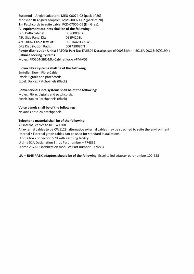
Euromod II Angled adaptors: MEU-00074-02 (pack of 20) Modsnap III Angled adaptors: MMS-00021-02 (pack of 20) 1m Patchcords to suite cable: PCD-07000-0E (E = Grey). All equipment cabinets shall be of the following: DRS Delta cabinet: D3P0000956 42U Side Panel Kit: D3SP4208L 42U 300w Cable tray kit: D3CTK42U300W DRS Distribution Rack: DDF42808CN Power distribution Units: EATON: Part No: EMIB04 Description: ePDUG3:Mtr I:IEC16A O:C13(20)C19(4) Cabinet Locking Systems Molex: PF0204-SBR-MU(Cabinet locks)-PM-V05 Blown Fibre systems shall be of the following: Emtelle: Blown Fibre Cable Excel: Pigtails and patchcords. Excel: Duplex Patchpanels (Black) Conventional Fibre systems shall be of the following: Molex: Fibre, pigtails and patchcords. Excel: Duplex Patchpanels (Black) Voice panels shall be of the following: Nexans Cat5e 24 patchpanels Telephone material shall be of the following: All internal cables to be CW1308 All external cables to be CW1128, alternative external cables may be specified to suite the environment Internal / External grade cables can be used for standard installations. Ultima box connection 520 with earthing facility Ultima 51A Designation Strips Part number – 774836 Ultima 237A Disconnection modules Part number - 774834 LJU – RJ45 PABX adapters should be of the following: Excel tailed adapter part number 100-628
Related Documents