1 STANDARD INDUSTRI PEMBINAAN (CONSTRUCTION INDUSTRY STANDARD) Stage Public Comment Date: 08/06/2018 – 13/07/2018 CIS 5: 2018 QUALITY ASSURANCE FOR PREFABRICATED TIMBER ROOF TRUSS SYSTEMS Descriptors: quality assurance, prefabricated timber truss systems, roof trusses, truss specifications, fabrication tolerances, installation tolerances, toothed metal plate connectors © copyright 2018 Lembaga Pembangunan Industri Pembinaan Malaysia

Welcome message from author
This document is posted to help you gain knowledge. Please leave a comment to let me know what you think about it! Share it to your friends and learn new things together.
Transcript
1
STANDARD INDUSTRI PEMBINAAN (CONSTRUCTION INDUSTRY STANDARD) Stage Public Comment
Date: 08/06/2018 – 13/07/2018
CIS 5: 2018 QUALITY ASSURANCE FOR PREFABRICATED TIMBER ROOF TRUSS SYSTEMS
Descriptors: quality assurance, prefabricated timber truss systems, roof trusses, truss specifications, fabrication tolerances, installation tolerances, toothed metal plate connectors
© copyright 2018 Lembaga Pembangunan Industri Pembinaan Malaysia
2
QUALITY ASSURANCE FOR PREFABRICATED TIMBER ROOF TRUSS SYSTEMS
3
Quality Assurance for Prefabricated Timber Roof Truss Systems © Construction Industry Development Board Malaysia 2018
All enquiries regarding this book should be forwarded to: Chief Executive Construction Industry Development Board Level 23, Sunway Putra Tower, No. 100, Jalan Putra, 50350 Kuala Lumpur, Malaysia Tel: 03-4047 7000/1300 88 2432 Fax: 03-4047 7070 E-mail: [email protected] Website: www.cidb.gov.my No part of this publication may be reproduced or transmitted in any form or any terms whether mechanical or electronic including photocopying or recording without the written consent of CIDB Perpustakaan Negara Malaysia Cataloguing-in-Publication Data ISBN ---------
4
TABLE OF CONTENTS Committee Representation 7
Foreword 8
SECTION 1: SCOPE AND GENERAL 9
1.1 Scope 9
1.2 Normative references 9
1.3 Abbreviations 10
1.4 Terms and definitions 10
SECTION 2: TRUSS DESIGN PROCESS 12
2.1 General 12
2.2 Documentation or records 12
2.2.1 Information required before commencement of design process 12
2.2.2 Discrepancies or deviations from drawings supplied 13
2.2.3 Information to be provided on truss design designs 13
2.3 Checking parameters 14
2.4 Checking personnel 15
2.5 Frequency of Checks 15
2.6 Acceptance criteria 15
2.7 Verification of truss design drawings 15
2.8 Responsibilities of the main contractor 15
SECTION 3. TRUSS FABRICATION PROCESS 16 3.1 General 16
3.2 Documentation or records 16
3.2.1 Fabrication equipment 16
3.2.2 Timber 17
3.2.3 Assembly of truss components or fabrication process 17 3.2.4 Storage 17
3.3 Checking parameters 17
3.3.1 Fabrication equipment 17
3.3.2 Timber 17
3.3.3 Assembly of truss components 18
3.3.4 Storage 18
3.4 Checking format 19
3.4.1 Fabrication equipment 19

5
3.4.2 Timber 19
3.4.3 Assembly of truss components 19
3.4.4 Storage 19
3.5 Frequency of checks 19
3.5.1 Fabrication equipment 19
3.5.2 Assembly of truss components 19
3.5.3 Storage 20
3.6 Acceptance criteria 20
3.6.1 Fabrication equipment 20
3.6.2 Assembly of truss components 20
3.6.2.1 For timber grade and species or strength group 20
3.6.2.2 For timber treatment 20
3.6.2.3 For timber sizes 21
3.6.2.4 For assembly and fabrication process 21
3.6.3 Storage 22
3.7 Verification and testing authority 23
3.7.1 Fabrication equipment 22
3.7.2 Timber 22
3.8 Rectification of trusses in factory 23
SECTION 4. SITE INSTALLATION PROCESS 23
4.1 General 23
4.2 Documentation or records 23
4.3 Checking parameters 23
4.4 Checking format 24
4.5 Frequency of checks 24
4.6 Acceptance criteria 25
4.7 Verification of truss design drawings 25
4.8 Rectification of trusses on site 25
SECTION 5. QUALITY ASSURANCE AUDIT TEAM 26
5.1 System Provider (SP) 26
5.2 Truss fabricator 26
5.3 Fabricator human resources 26
Annex A Steel for connector manufacturing 27
Annex B Summary of documentations and inspections 30

6
Annex C Process flow charts 32
FC 1 Total system quality check 33
FC 2.1 Truss plant equipment maintenance process 34
FC 2.2 Truss plant equipment maintenance process 35
(continued)
FC 3 Timber selection check in truss plant 36
FC 4 Stages for timber flow - Fabricator with licensed 37
timber grader
Annex D Checklist 38
CL 1 Checklist for truss design and details 42
CL 2 Checklist for truss fabricating equipment 45
CL 3 Checklist for documentation for site measurement 45
CL 4 Checklist for timber and trusses at truss plant 46
CL 5 Checklist for truss installation 50
Annex E MS 544: Part 2: 2001 Code of Practice for Structural Use of 58
Timber Part 2: Permissible Stress Design of Solid Timber -
Appendix C. Grading of Malaysian structural timber
Annex F MS544: 1978 - Table A.1 Classification of timbers in shrinkage 67
group
Annex G Terms applying to prefabricated timber roof trusses 70
Annex H Some examples of truss fabrication defects involving the 73
teethed metal plate (nail plate) connectors
References 78
Acknowledgment 79
LIST OF TABLE
Table 1 Roof truss installation tolerances 25

7
COMMITTEE REPRESENTATION
This Construction Industry Standard (CIS) was developed and reviewed by the Construction Industry
Development Board Malaysia with the assistance of the Technical Committee, which comprises
representatives from the following organisations:
Board of Engineers Malaysia (BEM)
Forest Research Institute Malaysia (FRIM)
Haustek Engineering Sdn. Bhd.
Institution of Engineers, Malaysia
Jabatan Kerja Raya (JKR)
Malaysian Timber Industry Board (MTIB)
Malaysia Wood Industry Association
Multinail Asia Sdn. Bhd.
MiTek Asia Sdn. Bhd.
Pertubuhan Arkitek Malaysia (PAM)
Persatuan Pengusaha Kayu Kayan dan Perabot Bumiputera Malaysia (PEKA)
Universiti Sains Malaysia (USM)
Universiti Teknologi MARA (UiTM)

8
FOREWORD This construction industry standard was first developed in 2004 and is revised as a quality assurance for
prefabricated timber roof truss with the assistance of the Construction Industry Development Board
(CIDB), which acted as a moderator and facilitator for the technical committee throughout the revision
process of the standard.
The main objective for the development of the quality assurance is to establish a detailed and systematic
framework to:
a) Ensure the quality of prefabricated timber trusses supplied to project sites are consistent with the
standard set for the product
b) Establish a common standard of acceptance for all relevant parties involved in the construction of
roof that uses such trusses (including project consultants and authorities)
c) Set minimum specifications to be used by connector plates manufacturers and truss fabricators
d) Identify relevant parties with the necessary expertise for each of the specific areas for conducting
the internal and external audits for the processes concerned.
Compliance with this document does not in itself confer immunity from legal obligations.
Chief Executive CIDB Malaysia

9
QUALITY ASSURANCE FOR PREFABRICATED TIMBER ROOF TRUSS SYSTEMS
1. SCOPE AND GENERAL 1.1 Scope This Quality Assurance System covers the main elements of the prefabricated timber truss that encompasses:
i. Stage 1- Truss Design Process
ii. Stage 2 - Truss Fabrication Process
iii. Stage 3 - Site Installation Process The relationship between each of these processes is illustrated in the flow chart FC 1. Total System Quality Check. Some aspects are checked more than once as the product moves through the production chain. For instance, checks for defects in timber that is used for trusses, which exceed the timber grading allowances, are carried out at Stage 2 and Stage 3.
1.2 Normative References
The referenced documents in this text constitute provisions of this Quality Assurance System. For dated references, where there are subsequent amendments to, or, revisions of, none of these publications do not apply. For undated references, the current edition of the publication is referred to and applied. i. MS 360 Specification for Treatment of Timber with Copper/Chrome/Arsenic
Wood Preservatives ii. MS 544-1 Code of Practice for Structural Use of Timber: Part 1: General iii. MS 544-2 Code of Practice for Structural Use of Timber: Part 2: Permissible Stress
Design of Solid Timber iv. MS 544 Part 6 Code of Practice for Structural Use of Timber: Part 6: Workmanship,
Inspection and Maintenance (First revision) v. MS 1714 Specification for Visual Strength Grading of Tropical Hardwood Timber vi. ANSI/TPI 1 National Design Standard for Metal Plate Connected Wood Truss
Construction viii. AS 1720.1 Timber Structures Part 1 - Design Methods x. JIS G 3302: 1987 Hot-dip Zinc-coated Steel Sheet and Strip xi. JKR 20601-0190-12 Specification for Prefabricated Timber Roof Trusses xii. Malaysian Grading Rules for Sawn Hardwood Timber 2009 Edition xiii. The system providers’ standards and specifications are derived from several companies, which are recognised by JKR.

10
1.3 Abbreviations i. CIDB Construction Industry Development Board Malaysia ii. FRIM Forest Research Institute Malaysia iii. JKR Jabatan Kerja Raya (Public Works Department) iv. MTIB Malaysian Timber Industry Board v. PE Professional Engineer registered with the Board of Engineers Malaysia vi. SAMM Malaysian Laboratory Accreditation Scheme (Skim Akreditasi Makmal Malaysia) vii. SP System Providers of prefabricated timber roof truss systems viii. STIDC Sarawak Timber Industry Development Corporation ix. TRTTC Timber Research and Technical Training Centre 1.4 Terms and Definitions For the purpose of this quality assurance system, the following terms and definitions apply. i. Truss system designer (SD)
A Professional Engineer who is responsible for the design of the specified roof truss system or systems, and producing the required engineering design drawings based on the relevant standards approved by the supervising authority.
ii. Supervising authority (SA) The authority responsible for ensuring that the contractual work is done and completed, as
specified in the contract within the stipulated period according to the accepted standards. iii. Supervising officer (SO)
A person who is responsible for ensuring that the contractual work is done and completed, as specified in the contract within the stipulated period according to the accepted standards.
iv. Truss system provider (SP) A supplier of a proprietary roof truss system, registered with MTIB. v. Truss system fabricator
A manufacturer capable of fabricating and producing proprietary roof truss systems using equipment and tools approved by an established truss system provider.
11
vi. Truss system installer
Contractor appointed by the System Provider or fabricator to assemble, erect and install the specified proprietary roof truss system on site.
vii. Accredited laboratory
Laboratory accredited under the Malaysian Laboratory Accreditation Scheme (SAMM), or equivalent, which is approved by the Supervising Authority and System Provider.
viii. Main contractor
A contractor defined in the main contract of work, who undertakes the obligation for the completion and delivery of work, as specified in the contract.
ix. Professional engineer (PE)
Trained professional engineer who is registered with the Board of Engineers Malaysia (BEM) and is a current practitioner (having active Practicing Certificate) in the registered field.
x. Project consultant engineer (CE)
A third-party professional engineer who is responsible to check the structural drawings and all the related engineering work as specified in the work contract. In this quality assurance document, the Consultant Engineer is referred to as consultant.
xi. Construction drawing
PE-approved drawing that represents the design principles and parameters, containing adequate information to produce fabrication drawings, and shall also contain adequate information on works to be done in the construction of all or a portion of the building structure.
xii. Fabrication drawing Drawing or set of drawings produced by the fabricator and verified by the PE to explain the
fabrication and/or installation to the installation team. The fabrication drawings show more details than the construction drawings, but shall not modify the design principle and technical specification stipulated in the construction drawings.
xiii. As-built drawing Revised set of drawings submitted by SP to the contractor showing the dimensions, geometry
and location of all elements of the work to be completed under the contract. xiv. Certified treated timber Timber treated in accordance to MS 544 - Part 10, or any other equivalent standards,
accompanied by treatment certificate or charge sheet, approved by MTIB. xv. Pre-fabricated truss Truss fabricated in a controlled setting on assembly line in an off-site facility, then delivered and
installed on site.

12
xvi. Certified pre-fabricated timber roof truss Roof truss fabricated in compliance with this Quality Assurance System by fabricators registered
with MTIB that is approved by an established truss System Provider, who is also registered with MTIB.
SECTION 2: TRUSS DESIGN PROCESS 2.1 General Prefabricated timber trusses are designed by either the System Provider or the truss designers of the System Provider’s truss fabricator using proprietary computer software developed by the individual System Provider. The software shall comply with the Codes of Practices stated below: i. AS 1720.1 Timber Structures Code Part 1 - Design Methods; or ii. ANSI/TPI 1 National Design Standard for Metal Plate Connected Wood Truss Construction;
or iii. MS 544 Code of Practice for Structural Use of Timbers
Part 1: General Part 2: Permissible stress design of solid timber Part 5: Timber Joints Part 8: Design, fabrication and installation of prefabricated timber roof
trusses using toothed metal plate connectors Part 9: Fire resistance of timber structures Part 10: Preservative treatment of structural timbers Part 11: Recommendations for the calculation basis for span tables
Independent engineering consultants may undertake the design of these trusses, but shall ensure that the correct design values for the connectors at the joints are utilised. These design values may be obtained from the System Provider. The manufacturer and product codes of the connectors shall be indicated on the design drawings and shall not be substituted without a complete redesign for connectors from another manufacturer. This section consists of the information required: i. To commence the truss design process
ii. To be shown on the truss design drawings upon completion of the truss design process Truss designs are checked for compliance with the drawings supplied to the Truss Fabricator either by the Main Contractor, or Supervising Authority. Any deviations or inability to meet with any of the requirements of the supplied drawings shall be informed by the SD to the Truss Fabricator for approval or resolution by the Main Contractor or SO. 2.2 Documentation or Records
2.2.1 Information required before commencement of design process To commence the design process, information required from the Main Contractor and Supervising Authority includes the following: i. Architectural drawings (comprising of roof plans, floor plans, elevations, sections, roof and ceiling
materials, positions of water tanks and other services, other details, etc.)
13
ii. Structural drawings (comprising of beam layout plans, top of beam levels)
iii. Mechanical and electrical services drawings (indicating positions of fan coils units, air-
conditioning ducting, hot water and chiller pipes, firefighting pipes, etc., which are to be supported by the roof trusses)
iv. Loads of the various elements of the mechanical and electrical services
v. Ceiling levels or areas of sloping ceiling
vi. Any special requirements (e.g. decorative features to be incorporated into truss structural members, matching of adjacent existing roofs, etc.)
vii. General truss limitation should be referred to related standards and specification, e.g. MS
544:2015 Part 8 and JKR 20601-0190-12-cl 2.2 2.2.2 Discrepancies or deviations from drawings supplied Discrepancies in architectural and structural drawings or inability to conform to the requirements of the drawings provided shall be handled in the following manner:
The affected areas or details shall be highlighted to the Truss Fabricator, and thereon, brought to the attention of the Main Contractor and Supervising Authority for resolution; or
Any proposed changes or modifications to the details of the affected areas shall be highlighted to the Truss Fabricator to be approved by the Main Contractor and Supervising Authority.
2.2.3 Information to be provided on truss design drawings The truss design drawings shall include the following information: i. Loading data
a) Dead loads b) Wind loads c) Water tank loads or capacities d) Mechanical and electrical services loads (where applicable)
ii. Timber design data a). Strength group and grade b) Joint group c) Moisture condition
iii. General truss design criteria a) Design wind speed b) Eaves height from ground level c) Truss spacing d) Top chord restraint centres (tile batten and purlin centres) e) Bottom chord restraint centres (ceiling batten and tie centres) f) Roof pitch

14
iv. Roof layout plan details
a) Individual truss and rafter position b) Marking or identification of each truss or rafter c) Eaves overhang dimension d) Building dimensions
v. Bracing layouts (where applicable)
a) Top chord plane b) Bottom chord plane c) Horizontal top chord plane
vi. Position of water tanks vii. Position of other services (if relevant) viii. Connection details such as
a) Hold-down at supports b) Truss to truss connections c) Rafter to truss connections d) Under purlin connections
Discrepancies in drawings supplied or any inability to conform to the drawings supplied that have not been resolved by the Main Contractor and Supervising Authority with the Truss Fabricator shall be noted on the design drawings together with any assumptions made to form the affected areas. In addition, for each individual truss, the following information shall be included: i. Truss profile with panel lengths, span, and height indicated ii. Timber component member sizes iii. Camber iv. Connector type, size, positioning and orientation v. Web tie bracing (where relevant) vi. Stiffener position and detail (where relevant)
All truss design drawings shall have a reference number that may be nominated by either the System Provider or the Truss Fabricator for identification, record filing and retrieval purposes. The records shall be retained for a period equivalent to the project warranty period or 5 years, whichever is longer by the Truss Fabricator with a copy retained by the System Provider. 2.3 Checking Parameters All designs done are checked for: i. Conformance with the architectural and structural drawings supplied to the Truss Fabricator by the Main Contractor ii. Correct design criteria iii. Adequacy of truss designs, bracing and connection requirements iv. Detailing and presentation of information and details (Checklist used: CL 1. Checklist for Truss Design and Detail)

15
2.4 Checking Personnel
The following parties shall check designs done by the System Provider: i. Professional Engineer ii. Main Contractor iii. Supervising Authority or Project Consultant Engineer
The following parties shall check designs done by the Truss Fabricator: i. System Provider ii. Professional Engineer iii. Main Contractor iv. Supervising Authority or Project Consultant Engineer After checking, the Professional Engineer shall endorse at least two sets of the drawings for submission to Supervising Authority or Project Consultant Engineer for their approval.
The Professional Engineer shall be experienced and competent in truss design systems.
The System Provider shall issue a design warranty letter for the design checked to the Truss Fabricator for submission to the Main Contractor or Supervising Authority. 2.5 Frequency of Checks
For design drawings done by System Provider, the drawings shall be checked for every project by Main Contractor and Supervising Authority. For design drawings done by Truss Fabricator, the drawings shall be checked for every project by System Provider, Main Contractor and Supervising Authority. 2.6 Acceptance Criteria
The truss designs are accepted if deemed to conform with the design codes of practice stated above; the supplied architectural and structural drawings, the design criteria, adequacy of the truss, bracing and connection details conform to recognized standards.
Instructions by the Main Contractor to the Fabricator to commence truss fabrication shall be taken as all necessary approvals are given and all proposed changes, modifications or assumptions taken to form the truss are accepted by the relevant authorities or parties. 2.7 Verification of Truss Design Drawings All truss design drawings shall be endorsed by the checking Professional Engineer. 2.8 Responsibilities of the Main Contractor The Main Contractor shall be responsible for any changes or amendments to the architectural or structural details that are not reflected on the drawings that are supplied to the Truss Fabricator at the truss design stage. This shall also include changes to mechanical and electrical service loading details.

16
SECTION 3. TRUSS FABRICATION PROCESS 3.1 General This section covers timber processing and the assembly or fabrication of the cut timber components and connectors into trusses in the Truss Fabricator’s factory premises. Jigs are used to hold or clamp the various cut timber components in position with the fixing of the toothed metal plate connectors at the truss joints carried out using hydraulic presses. This section is divided into the following sub-sections: i. Fabrication equipment ii. Timber iii. Assembly of truss components or fabrication process iv. Storage. Note: Site measurement by the Truss Fabricator of the supporting building structure is recommended prior to cutting truss components (refer to Section 4.1 and Checklist CL 3. Checklist for documentation for site measurement).
3.2 Documentation or Records The records shall be retained for a period equivalent to the project warranty period or 7 years, whichever is longer by the Truss Fabricator, with a copy retained by the Truss Designer. 3.2.1 Fabrication Equipment (Checklist used: Form CL 2. Checklist for Truss Fabrication Equipment) 3.2.2 Timber The Truss Fabricator shall utilise the checklist for each project undertaken by the Truss Fabricator. The checklist shall be maintained for inspection by the System Provider, Main Contractor and Supervising Authority. For certification, MTIB shall verify the checklist. For each batch of timber, the following records shall be furnished by the fabricator with the minimum information as listed below and retained: i. Grading summary by MTIB-registered or STIDC-registered timber grader
a) Batch identification number b) Nominal timber sizes and quantity c) Type of species or strength group d) Visual grade e) Name of grader and MTIB or STIDC registration number
ii. Preservative vacuum pressure-treatment certificate and charge sheet
a) Batch identification number b) Nominal timber sizes and quantity c) Name of treatment plant d) Date of treatment e) Type of chemical used and chemical manufacturer’s name f) Treatment chemical retention or treatment charge

17
Test results of treated timber samples that were sent to chemical suppliers’ test laboratories by Truss Fabricators for the purpose of monitoring the performance of the treatment plants (both in-house or external facilities) shall also be filed with relevant timber batches for audit purposes.
All grading summaries and treatment certificates or charge sheets shall be filed in a manner that allows easy retrieval and identification of relevant timber batches for inspection or audit purposes. (Checklist used: Form CL 4. Checklist for Timber and Trusses at Truss Plant) 3.2.3 Assembly of truss components or fabrication process
The Truss fabricator shall utilise the checklist for each project undertaken by the Truss Fabricator. Checklists shall be maintained for inspection by the System Provider, Main Contractor and Supervising Authority. (Checklist used: Form CL 4. Checklist for Timber and Trusses at Truss Plant) 3.2.4 Storage (Checklist used: For CL 4. Checklist for Timber and Trusses at Truss Plant)
3.3 Checking Parameters 3.3.1 Fabrication equipment The sawing equipment are checked for: i. General condition of the saw assembly ii. Alignment of saw bench iii. Cut squareness iv. Accuracy of angles cut The hydraulic pressing equipment are checked for:
i. Condition of the hydraulic system (leakage at hoses or valves, hydraulic system pressure and condition of hydraulic oil)
ii. Condition of electrical controls iii. Condition of jig frame and boxes (for portal gantry or A-frame systems) (Refer to Flow Charts FC 2.1. and FC 2.2.: Truss Plant Equipment Maintenance Process) 3.3.2 Timber The grading summary of the timber batch to be used shall be checked for conformance with the truss design criteria indicated on the design drawings: i. Visual grade ii. Species or strength group
The preservative vacuum pressure-treatment certificate or charge sheet shall be checked to ensure it corresponds with the treatment the timber batch is stated to be using:

18
i. The vacuum-pressure process ii. Copper-chrome-arsenic based chemicals or other approved wood preservatives iii. Retention of the preservative chemical corresponding with the current version of MS 360
requirements or other relevant Codes of Practice for the stated use of the timber. Test results of treated timber samples sent by the Truss Fabricator to monitor the performance of the treatment facilities (both in-house and external facilities) shall be reviewed. Any corrective action taken will be noted. Note: The checks on the cross-sectional dimensions and allowable timber defects of the timber used for truss fabrication at the
Truss Fabricator’s factory shall be carried out during the checks on fabricated trusses (Refer Section 3.6.2).
3.3.3 Assembly of truss components The parameters required to be checked includes the following: i. Truss geometry (check on overall dimensions, e.g. span, height, panel lengths) ii. Timber member sizes (cross-section dimensions conform with design drawing requirements)
iii. Timber defects (not exceeding the limits specified for the grade of timber used)
iv. Joint timber tolerances
a) Variation in timber thickness between any 2 abutting adjacent members b) Gap between the ends of any 2 adjacent members
v. Connector type and size vi. Joint connector tolerances
a) Embedment of connector teeth
b) Placement
vii. Connector orientation viii. Teeth roll-over ix. Damaged connector or joint
x. Missing connector 3.3.4 Storage
The completed trusses, that are stored in the Fabricator’s yard while awaiting delivery to site, are checked for the following parameters: i. Bundling off ground ii. Stacking in a flat position with supporting blocks under panel points
iii. Marking or identification of individual trusses stacked
19
If the completed trusses are to be stored in the yard for more than two (2) weeks, then these trusses should be protected from the elements in a manner that provides adequate ventilation to the trusses. If tarpaulins or other similar materials are used, the ends should be left open for ventilation. 3.4 Checking Format 3.4.1 Fabrication equipment
Audit of equipment shall be carried out by the System Provider or its representative.
3.4.2 Timber The System Provider shall review the following documentation: i. Timber grade, species or strength group and size
a) Details on the grading summary by MTIB- or STIDC-registered timber grader to conform
b) With the truss design requirements for visual grade, species or strength group c) Timber cross-section dimensions
ii. Timber treatment
a) Details on the treatment certificate issued to the treatment plant by MTIB are reviewed by the System Provider for the correct treatment charge used
3.4.3 Assembly of Truss Components
For randomly selected batches, the System Provider shall check the trusses for conformance with the truss design drawings and the tolerances specified by the System Provider for fabrication are met in accordance to the parameters stated above.
3.4.4 Storage Completed trusses in the factory shall be inspected by the System Provider to check whether they are stacked and stored in accordance with the System Provider’s recommended practices. 3.5 Frequency of Checks
The Truss Fabricator shall carry out the truss fabrication quality control process at least once every two (2) years and retain the records for the System Provider’s audits.
The System Provider shall conduct audits on the Truss Fabricator’s manufacturing facilities at least once a year, or upon the Truss Fabricator’s request, or if deficiencies are discovered in the previous audit and verified by MTIB.
3.5.1 Fabrication equipment
Checks for all sawing and pressing equipment shall be carried out annually . 3.5.2 Assembly of truss components
During the System Provider’s audit, a truss fabrication batch is randomly selected for checking at the above frequency. Ten (10) random trusses are picked from the batch and checked for the parameters stated in 3.4.2.

20
Sampling may be repeated as stated under the Acceptance Criteria.
3.5.3 Storage
The System Provider shall conduct its audit at the frequency stated in Section 3.5.2.
3.6 Acceptance Criteria 3.6.1 Fabrication equipment
Equipment shall be in good general order with the saw benches aligned, and for the presses, minimal leakage along the hydraulic hoses and valves. Sawing tolerances shall not exceed the following: i. ± 2 degrees off-vertical for timber thickness for cut squareness (refer to note below) ii. ± 1 degree for accuracy of angles cut Note: The cutting shall not result in the joint gaps exceeding the limits specified in 3.6.2.4 d for all member thicknesses.
For the hydraulic presses, the hydraulic pressure shall be able to be maintained when clamping on a piece of timber and held for 2 seconds. 3.6.2 Assembly of truss components For each batch of trusses inspected, the following documents shall be made available: i. Grading summary by a MTIB- or STIDC-registered timber grader, stating the timber grade and
species or timber strength group ii. Treatment certificate from MTIB or STIDC or FRIM or TRTTC, which shall bear the name of the
chemical supplier, type of chemical, treatment charge used, and the treater 3.6.2.1 For timber grade and species or strength group The grade and species or strength group in the grading summary shall comply with the truss design criteria.
Samples may be required to be sent for testing by an independent party (as defined in Section 3.7.2 below) for confirmation if the relevant certificates are not available. For 10 trusses selected, if more than 5% of the timber components are found to have defects exceeding the limits specified by the current version of MS 544: Part 2 or MS 1714, or, the cross-section size is less than the design specified sizes, a further 10 trusses from the same batch shall be selected at random for further checking. If no more than 5% non-permissible defects are found in the second sampling, the batch shall be deemed to meet the specifications with the defective pieces replaced or strengthened. If more than 5% of components have non-permissible defects in the second 10 trusses, then the entire batch shall be checked for compliance.
3.6.2.2 For timber treatment All roof timbers shall be treated to a charge of not less than 5.6 kg/m3 (0.35 lb/ft3) for CCA preservatives to achieve the necessary salt retention for non-durable timber and sapwood of durable species. For other approved preservative chemicals, the relevant Codes of Practice should be referred to.

21
If the charge is less than 5.6 kg/m3, the timber batch shall either be rejected or sent through the treatment process again in order to satisfy the acceptance criteria. For species that require treatment, the minimum preservative penetration depth for timber is 6 mm (MS 360). If no treatment certificate is available for the timber batch, then that batch shall not be utilised for fabrication.
3.6.2.3 For timber sizes At the time of fabrication, the cross-section dimensions shall not be less than the specified design sizes. Note: i. Sizes referred to in design drawings are at the time of truss fabrication. Upon drying out, green timber shall undergo
shrinkage in dimensions. This Quality Assurance shall adopt an average of 3% as the magnitude of shrinkage for species commonly used in truss fabrication (refer to Annex F).
ii. Note that there is an increase in timber strength as the timber dries (refer to Table 1. Wet grade stresses of timber, Table
2. Dry grade stresses of timber and Table 4. Wet and dry grade stresses for various groups of timber of MS 544: Part 2).
3.6.2.4 For assembly and fabrication process Trusses fabricated are deemed acceptable if: i. Their overall geometry conforms with the design truss profiles (taking into account of adjustments for variations in building dimensions based on site measurements taken) ii. Timber member sizes are of at least specified in the design drawings (refer to 3.6.2.3 “Note” on
timber shrinkage) iii. Timber defects do not exceed sizes specified in the current version of MS 544: Part 2 or MS 1714
for visual grading (refer to Annex E) iv. Joint timber tolerances do not exceed the limits below:
a) Variation in timber thickness between any two (2) abutting adjacent members is 2mm or
less b) Average gap between the ends of any two (2) abutting adjacent members is
2mm or less;
v. Connector type and size is not less than specified in the design drawings:
a) Connectors that project outside the edges of the timber are allowed if designed for and their placement do not deviate by more than the tolerances specified;
vi. Tolerances for the connectors at the truss joint do not exceed the limits below:
a) Gap between the underside of connector to the timber surface is 1.5mm or less b) Embedment of the connector plate is not more than 0.5mm c) Mispositioning of connector by not more than 6mm for connector dimension of less than
150mm (in the direction of the dimension), and 12mm for connector dimension of 150mm or more (in the direction of the dimension)
vii. Orientation of connector to conform with System Provider specifications and standards, and truss design drawings

22
viii. Number of teeth rolled-over or flattened shall not exceed 10% of available teeth
ix. No detectable damage to the connectors or joint
x. No missing connectors at the joint The System Provider shall then undertake engineering assessment to determine what steps are required, if any, to rectify any trusses that do not meet the above acceptance criteria.
Any trusses, in the opinion of the System Provider, that cannot be rectified shall be rejected and disposed by the Truss Fabricator. 3.6.3 Storage
The completed trusses shall be stored in the following manner in accordance with requirements of the System Provider: i. Bundles are off the ground and not in direct contact with the ground ii. Stacked in a flat position with supporting blocks under panel points iii. Individual trusses stacked are marked or identified clearly
3.7 Verification and Testing Authority 3.7.1 Fabrication equipment
MTIB shall verify the documentation for the maintenance of the fabrication equipment. 3.7.2 Timber (Refer to Annex C - Flow Chart FC 4. (a) to (c): Stage for Timber Verification) Where further verification is required, tests shall be carried out at any of the following organisations:
i. For timber grade verification
a) Malaysian Timber Industry Board b) Sarawak Timber Industry Development Corporation
ii. For timber species verification
a) Malaysian Timber Industry Board b) Forest Research Institute Malaysia c) Sarawak Timber Industry Development Corporation d) Timber Research and Technical Training Centre
iii. For timber treatment verification
a) Malaysian Timber Industry Board b) Forest Research Institute Malaysia c) Timber Research and Technical Training Centre d) Laboratories registered under SAMM
23
3.8 Rectification of Trusses in Factory Checked trusses that do not meet the fabrication specifications or are damaged in the Fabricator’s factory may be rectified provided: i. The System Provider and/or Professional Engineer engaged by Truss Fabricator agrees that the
said trusses can be rectified, and ii. Rectification details are provided by the System Provider and/or Professional Engineer engaged by Truss Fabricator, or iii. Rectification details are approved by the System Provider and/or Professional Engineer engaged
by Truss Fabricator in writing
SECTION 4. SITE INSTALLATION PROCESS 4.1 General This section covers the area of truss installation at the site, where materials and workmanship are checked against the details of the design drawings and recommended installation tolerances.
Site measurements are recommended to be taken prior to fabrication of the trusses to allow for site construction deviations or tolerances of the supporting structure. However, it remains the responsibility of the Main Contractor to advise the Truss Fabricator of any changes or amendments to the architectural or structural details (including mechanical and electrical services) that are not reflected in the drawings supplied to the Truss Fabricator at design stage. 4.2 Documentation or records The checklist is generally used when the truss installation works is either completed or close to completion. Note: The use of checklist Form CL 3. Checklist for Documentation for Site Measurement will highlight or minimise any
discrepancies between the design criteria or details and the actual site situation.
A CL 5 checklist shall be used for each individual stand-alone building or for a block of units with a similar roof design. Block identification shall be indicated on the relevant checklist. The records shall be retained for a period equivalent to the project warranty period or 5 years, whichever is longer by the fabricator with a copy retained by the System Provider. (Checklist used: Form CL 5. Checklist for Truss Installation) 4.3 Checking Parameters
The parameters required to be checked for both materials used and workmanship for the installation of: i. Wall-plates along beams used for truss support ii. Trusses and rafters
iii. Erection tolerances
24
iv. Bracing
v. Other framing components
vi. Presence of service loads
vii. Tile battening (if applicable)
viii. Purlins (if applicable)
ix. Fascia board 4.4 Checking format A joint-site inspection, coordinated by the main contractor, shall be carried out upon completion of roof truss installation (prior to ceiling installation) by: i. Truss Fabricator’s site coordinator or supervisor ii. System Provider’s technical personnel or its authorised representative iii. Main Contractor’s representative
iv. Professional Engineer who endorsed the truss design drawings or his/her authorised representative
The Consultant or Supervising Authority’s personnel shall be informed of the joint inspection and invited to witness the inspection. All trusses shall be visually checked for obvious misalignment and incorrect spacing. To verify that the spacings and alignments of the installed trusses are within design tolerance, a number of trusses shall be chosen randomly for these measurement checks based on the following criteria: i. 10% per cent of all installed trusses ii. A maximum of ten (10) numbers of trusses, whichever is lower
If the total number of trusses is less than 10, then all the installed trusses in the roof shall be checked. If the requirements of the checking parameters are not met, a further number of trusses are selected based on the above criteria for additional inspection. In the event that non-conformance are detected in the second sampling, all the roof trusses shall be checked. All detected non-conformances shall then be rectified in accordance with 5.8. Inspection of the roof or roof elements at other stages of installation shall be at the discretion of the parties involved.
4.5 Frequency of Checks
Joint inspections shall be carried out at least once for every project.
25
4.6 Acceptance Criteria Workmanship shall conform with the details in the truss design drawing. System Provider’s Installation Guide, the current versions of MS 544: Part 6 and System Provider’s requirements.
Timber defects shall not exceed the timber grading requirements as defined by the current version of MS 544: Part 2 and MS 1714 for the specified grade.
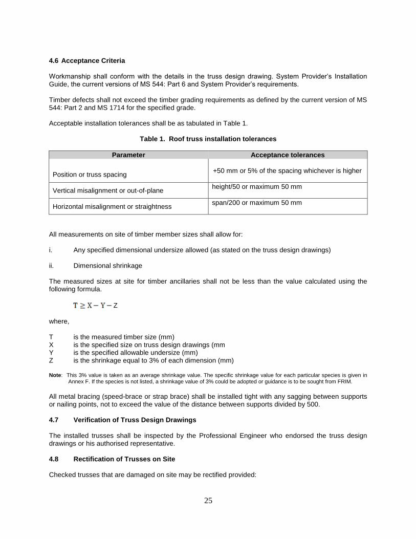
Acceptable installation tolerances shall be as tabulated in Table 1.
Table 1. Roof truss installation tolerances
Parameter Acceptance tolerances
Position or truss spacing
+50 mm or 5% of the spacing whichever is higher
Vertical misalignment or out-of-plane height/50 or maximum 50 mm
Horizontal misalignment or straightness span/200 or maximum 50 mm
All measurements on site of timber member sizes shall allow for: i. Any specified dimensional undersize allowed (as stated on the truss design drawings) ii. Dimensional shrinkage The measured sizes at site for timber ancillaries shall not be less than the value calculated using the following formula.
Z
where, T is the measured timber size (mm) X is the specified size on truss design drawings (mm Y is the specified allowable undersize (mm) Z is the shrinkage equal to 3% of each dimension (mm) Note: This 3% value is taken as an average shrinkage value. The specific shrinkage value for each particular species is given in
Annex F. If the species is not listed, a shrinkage value of 3% could be adopted or guidance is to be sought from FRIM.
All metal bracing (speed-brace or strap brace) shall be installed tight with any sagging between supports or nailing points, not to exceed the value of the distance between supports divided by 500. 4.7 Verification of Truss Design Drawings The installed trusses shall be inspected by the Professional Engineer who endorsed the truss design drawings or his authorised representative. 4.8 Rectification of Trusses on Site Checked trusses that are damaged on site may be rectified provided:
26
i. The System Provider agrees that the said trusses can be rectified ii. Rectification details are provided by the System Provider
iii. Rectification details are approved by the System Provider in writing. The rectification details shall be approved by the Professional Engineer with a copy submitted to the Main Contractor. SECTION 5. QUALITY ASSURANCE AUDIT TEAM 5.1 System Provider (SP)
Each System Provider shall form an audit and inspection team under the supervision of an engineer for implementing and maintaining the Quality Assurance System.
Members of the team shall be experienced or are trained in at least one or more of the process areas under the scope of this Quality Assurance System and are to audit or inspect these process areas only.
Factory inspections are to be carried out on a random basis, provided production is scheduled for the nominated day.
Site installation inspections are carried out as soon as practicable prior to handing over of the works by the Truss Fabricator.
This team shall liase with any other third party involved in auditing for this Quality Assurance System (refer to Annex B - Summary of Documentation and Inspections).
5.2 Truss Fabricator Each fabricator shall identify their personnel who shall have quality assurance responsibilities at their operations.
The suggested personnel shall be: i. General Manager : overall executive responsibility ii. Technical Manager or Designer : design and detailing
iii. Factory Manager or Supervisor : production and distribution
iv. Technical Manager or Supervisor: site installation
5.3 Fabricator Human Resources The technical competency of the personnel involved in the following process areas shall be audited annually by the System Provider: i. Design and detailing ii. Production and distribution iii. Site installation

27
ANNEX A (normative)
STEEL FOR CONNECTOR MANUFACTURING
A1 General This section is to confirm that the steel supplied for the manufacture of toothed metal plate connectors meet the specifications required to ensure the design values of the connectors are met. Toothed metal plates are used as connectors in the fabrication of the prefabricated timber truss systems. These connectors are manufactured from light gauge galvanized steel having teeth punched out in one direction and bent perpendicular to the base of the plate. The galvanized steel is supplied to the System Providers or manufacturers of the toothed metal plates in the form of coils.
A2 Documentation or records
The steel supplier’s Mill Test Certificate is to accompany each shipment.
The minimum information required on the certificates shall include the following: i. Suppliers’ name ii. Coil number or shipment number iii. Date of shipment iv. Coil thickness and width v. Steel mechanical properties (tensile strength, yield strength and elongation) vi. Galvanizing coating mass or galvanizing standard used All mill test certificates shall be filed based on the coil number/shipment number or the date of shipment and retrieved, if necessary, for inspection or audit purposes. The records shall be retained for a minimum period of five years by the System Provider.
A3 Checking parameters The following properties of the steel coils shall be tested and confirmed by an accredited laboratory as specified in A7 of this Annex: i. Mechanical properties
a) Ultimate steel tensile strength b) Minimum steel yield strength c) Elongation
ii. Anti-corrosion coating iii. Galvanizing coating mass
iv. Coil thickness A4 Checking format
The Mill Test Certificate(s) of all coil shipments received shall be checked for conformance with the acceptance standard for the parameters stated by the System Provider.
28
In addition, samples selected from coils at random, shall be sent to an accredited test laboratory to verify that the minimum mechanical properties and galvanizing coating masses are achieved. A5 Frequency of checks
The System Provider shall check the Mill Test Certificate for every shipment received. One sample from a coil selected at random shall be sent. In addition, at a minimum frequency of once every six months, one sample from a coil selected at random, shall be sent to an accredited test laboratory A6 Acceptance criteria
Criteria for acceptance shall be based on the following standards or other approved equivalent standards: i. Steel mechanical properties
a) AS 1397: 2011 Table 2.2 - Mechanical Property Requirements for Structural Grades and
Table 2.3 - Mechanical Property Requirements for Formability/Grades, or
b) JIS G 3302 Table 7.8 - Yield Point, Tensile Strength, Elongation and Non-aging (cold-rolled base metal used)
ii. Galvanizing coating mass
a) AS 1397: 2011 Table 3.1 - Coating Mass Requirements, or
c) JIS G 3302 Table 2 - Minimum coating mass on both surfaces for sheets or coils
having same coating mass on both surfaces
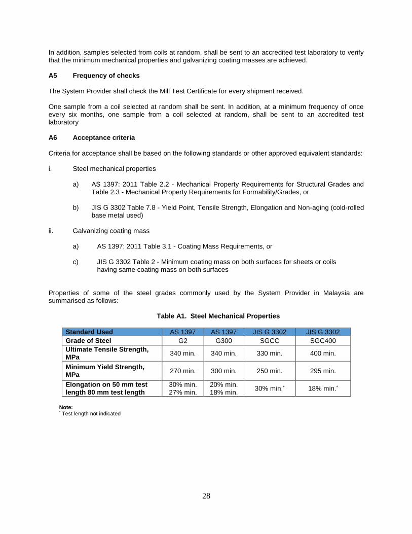
Properties of some of the steel grades commonly used by the System Provider in Malaysia are summarised as follows:
Table A1. Steel Mechanical Properties
Standard Used AS 1397 AS 1397 JIS G 3302 JIS G 3302
Grade of Steel G2 G300 SGCC SGC400
Ultimate Tensile Strength, MPa
340 min. 340 min. 330 min. 400 min.
Minimum Yield Strength, MPa
270 min. 300 min. 250 min. 295 min.
Elongation on 50 mm test length 80 mm test length
30% min. 27% min.
20% min. 18% min.
30% min.* 18% min.*
Note: * Test length not indicated
29
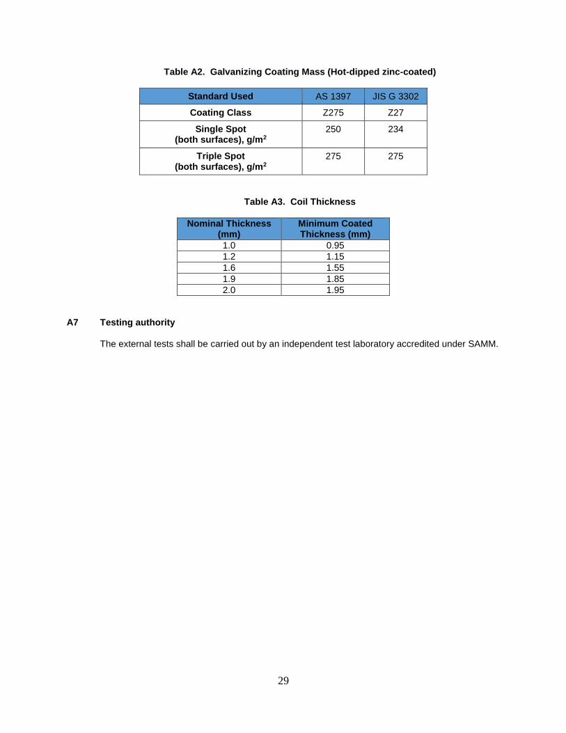
Table A2. Galvanizing Coating Mass (Hot-dipped zinc-coated)
Standard Used AS 1397 JIS G 3302
Coating Class Z275 Z27
Single Spot (both surfaces), g/m2
250 234
Triple Spot (both surfaces), g/m2
275 275
Table A3. Coil Thickness
Nominal Thickness (mm)
Minimum Coated Thickness (mm)
1.0 0.95
1.2 1.15
1.6 1.55
1.9 1.85
2.0 1.95
A7 Testing authority
The external tests shall be carried out by an independent test laboratory accredited under SAMM.

30
ANNEX B (normative)
SUMMARY OF DOCUMENTATION AND INSPECTIONS
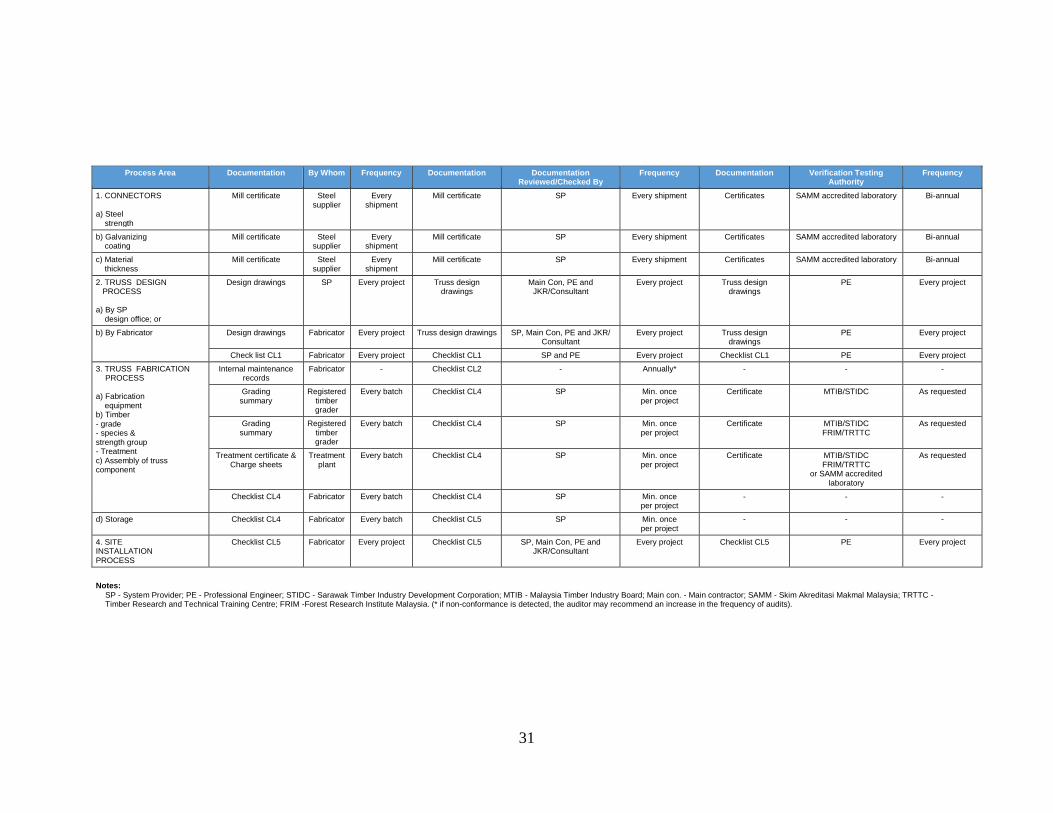
Table B1. Summary of documentation and inspections
31
Notes:
SP - System Provider; PE - Professional Engineer; STIDC - Sarawak Timber Industry Development Corporation; MTIB - Malaysia Timber Industry Board; Main con. - Main contractor; SAMM - Skim Akreditasi Makmal Malaysia; TRTTC - Timber Research and Technical Training Centre; FRIM -Forest Research Institute Malaysia. (* if non-conformance is detected, the auditor may recommend an increase in the frequency of audits).
Process Area Documentation By Whom Frequency Documentation Documentation Reviewed/Checked By
Frequency Documentation Verification Testing Authority
Frequency
1. CONNECTORS a) Steel strength
Mill certificate Steel supplier
Every shipment
Mill certificate SP Every shipment Certificates SAMM accredited laboratory Bi-annual
b) Galvanizing coating
Mill certificate Steel supplier
Every shipment
Mill certificate SP Every shipment Certificates SAMM accredited laboratory Bi-annual
c) Material thickness
Mill certificate Steel supplier
Every shipment
Mill certificate SP Every shipment Certificates SAMM accredited laboratory Bi-annual
2. TRUSS DESIGN PROCESS a) By SP design office; or
Design drawings SP Every project Truss design drawings
Main Con, PE and JKR/Consultant
Every project Truss design drawings
PE Every project
b) By Fabricator Design drawings Fabricator Every project Truss design drawings SP, Main Con, PE and JKR/ Consultant
Every project Truss design drawings
PE Every project
Check list CL1 Fabricator Every project Checklist CL1 SP and PE Every project Checklist CL1 PE Every project
3. TRUSS FABRICATION PROCESS
a) Fabrication equipment b) Timber - grade - species & strength group - Treatment c) Assembly of truss component
Internal maintenance records
Fabricator - Checklist CL2 - Annually* - - -
Grading summary
Registered timber grader
Every batch Checklist CL4 SP Min. once per project
Certificate MTIB/STIDC As requested
Grading summary
Registered timber grader
Every batch Checklist CL4 SP Min. once per project
Certificate MTIB/STIDC FRIM/TRTTC
As requested
Treatment certificate & Charge sheets
Treatment plant
Every batch Checklist CL4 SP Min. once per project
Certificate MTIB/STIDC FRIM/TRTTC
or SAMM accredited laboratory
As requested
Checklist CL4 Fabricator Every batch Checklist CL4 SP Min. once per project
- - -
d) Storage Checklist CL4 Fabricator Every batch Checklist CL5 SP Min. once per project
- - -
4. SITE INSTALLATION PROCESS
Checklist CL5 Fabricator Every project Checklist CL5 SP, Main Con, PE and JKR/Consultant
Every project Checklist CL5 PE Every project

32
ANNEX C (normative)
PROCESS FLOW CHARTS
FC 1. Total System Quality Check
FC 2.1. Truss Plant Equipment Maintenance Process
FC 2.2. Truss Plant Equipment Maintenance Process (continued)
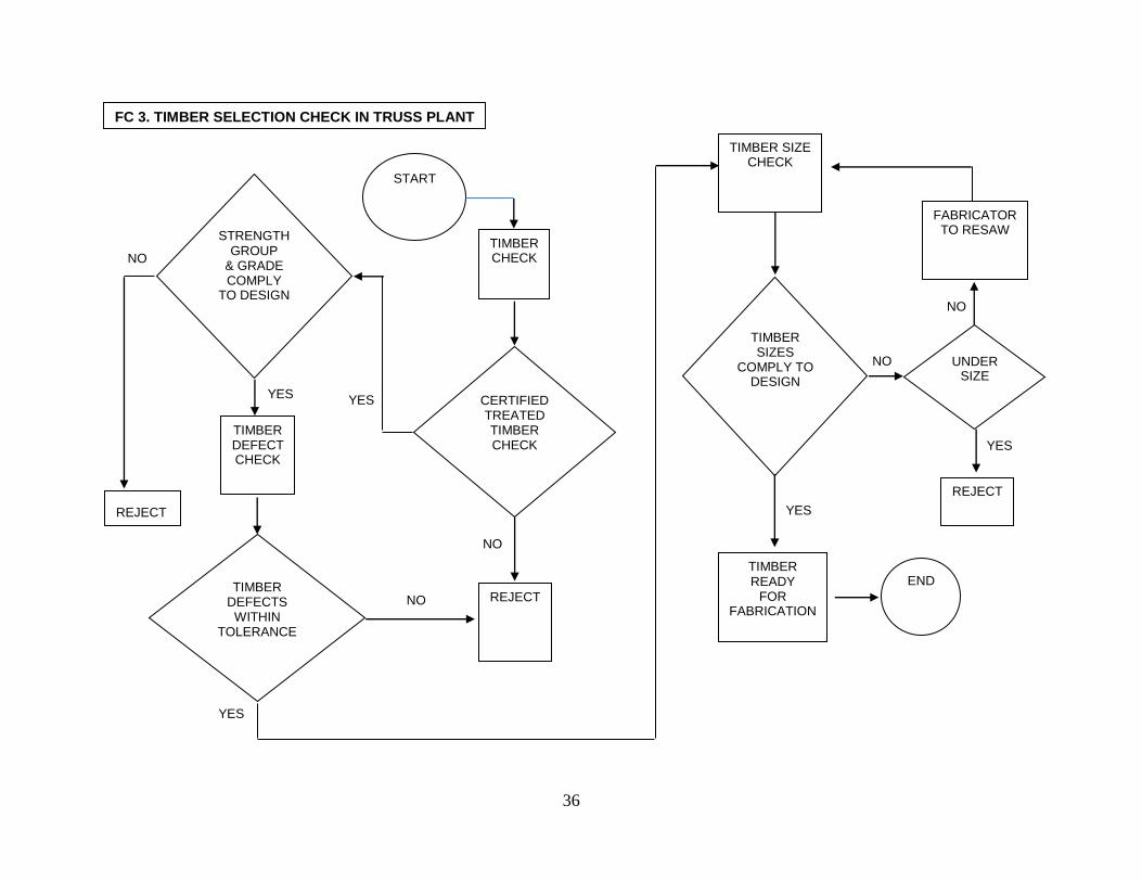
FC 3. Timber Selection Check in Truss Plant
FC 4. Stages for Timber Flow – Fabricator with Licensed Timber Grader:
a) a) Truss Fabricator/Sawmill with licensed timber grader b) Truss Fabricator with treatment facilities c) Truss Fabricator without treatment facilities

33
START
CONNECTOR PLATE CHECK
CONNECTOR QUALITY IS OK
SP PRODUCTION TAKE ACTION
YES
TRUSS PLANT EQUIPMENT
CHECK
ALL EQUIPMENT CONDITION
IS OK
NO
YES
SP EQUIPMENT TEAM/
TRUSS PLANT MECHANIC
TO FIX
NO
YES
TIMBER CHECK
TIMBER COMPLY TO DESIGN &
SPECIFICATION
FABRICATOR’S RESPONSIBILITY
TO COMPLY NO
YES
NO
YES
TRUSS INSTALLATION
CHECK
TRUSS INSTALLATION ACCORDING
TO DRAWINGS
FABRICATOR’S RESPONSIBILITY
TO COMPLY & SP/PE
ADVICE RECTIFICATION
NO
YES
QAS COMPLIED END
NOTE:
SP - System Provider
PE – Professional Engineer
TRUSS DESIGN
FABRICATION WITHIN
TOLERANCE
SP TO ADVICE RECTIFICATION
TRUSS FABRICATION
TOLERANCE CHECK
TRUSS AT SITE CHECK
(PRIOR INSTALLATION) TRUSS
HANDLING IS OK
SP TO ADVICE
RECTIFICATION
NO
FC 1. TOTAL SYSTEM QUALITY CHECK

34
START
CUTTING EQUIPMENT
CHECK
SAW BENCH CHECK
TO MAKE GOOD
SAW PHYSICAL
CONDITION
TO MAKE GOOD
SAW ANGLE
CALIBRATION
TO CALIBRATE
PRESSING EQUIPMENT
CHECK
HYDRAULIC OIL/FILTER CONDITION
TO CLEAN /REPLACE
HYDRAULIC HOSES & VALVES
CONDITION
TO REPAIR /REPLACE
CONTROL BUTTONS ARE
WORKING
TO REPAIR /REPLACE
NO
NO
NO
YES
YES
YES
HYDRAULIC PRESSURE
IS RIGHT
ADJUSTMENT TO RIGHT
PRESSURE
NO
OK
YES
OK
YES
NO
NOT OK
NOT OK
TO FC 2.2 PORTAL OR ‘A’ FRAME
FC 2.1. TRUSS PLANT EQUIPMENT MAINTENANCE PROCESS
TO FC 2.2 BENCH PRESS

35
REPAIR AND PUT TO
THE CORRECT LEVEL
HYDRAULIC HOSES & VALVES
CONDITION
TO REPAIR /REPLACE
HYDRAULIC PRESSURE
IS RIGHT
ADJUSTMENT TO RIGHT
PRESSURE
NO
OK
YES
YES
NO
NOT OK
PORTAL OR ‘A’ FRAME BRAKE SYSTEM
IS WORKING
ADJUST TO RIGHT
BRAKE PRESSURE
YES
NO
BENCH PRESS EQUIPMENT
CHECK
TO CLEAN /REPLACE
OK
NOT OK HYDRAULIC OIL/FILTER CONDITION
END
FROM FC 2.1
FC 2.2 TRUSS PLANT EQUIPMENT MAINTENANCE PROCESS (continued)
FROM FC 2.1
JIG TABLE & FLO BOXES ON FLAT
LEVEL
36
FC 3. TIMBER SELECTION CHECK IN TRUSS PLANT
TIMBER SIZES
COMPLY TO DESIGN
NO
YES
TIMBER SIZE CHECK
TIMBER DEFECTS
WITHIN TOLERANCE
NO
YES
TIMBER DEFECT CHECK
TIMBER READY
FOR FABRICATION
END
START
TIMBER CHECK
STRENGTH GROUP
& GRADE COMPLY
TO DESIGN
YES
REJECT
REJECT
FABRICATOR TO RESAW
YES
NO
CERTIFIED TREATED TIMBER CHECK
NO
YES
NO
REJECT
UNDER SIZE

37
Timber selection
Seasoning
Grading
Treatment (If required)
Cutting
Truss Fabrication
Delivery
Install at site
Verification (grading, species &
treatment)
No
Yes
Retreatment
Treated Timber
Certification
Prefabricated Timber Roof Truss
Certification
Note: For Fabricator without treatment plant, the in-coming timber in the fabricator’s factory shall be certified treated timber For Fabricator without a licensed timber grader, arrangement can be made with MTIB or STIDC for timber grading services.
FC 4. STAGES FOR TIMBER FLOW - FABRICATOR WITH LICENSED TIMBER GRADER
Treated timber
Certification compliance

38
ANNEX D (Informative)
CHECKLISTS
CL 1. Checklist for Truss Design & Detail
CL 2. Checklist for Truss Fabricating Equipment
CL 3. Checklist for Documentation for Site Measurement
CL 4. Checklist for Timber and Trusses at Truss Plant
CL 5. Checklist for Truss Installation

39
CL 1. Pg CL1/1 of 3
CHECKLIST FOR TRUSS DESIGN & DETAILS
Date: ________ Fabricator Name: _______________________________________________________ Project Title: __________________________________________________ __________________________________________________
__________________________________________________ __________________________________________________
Job No.: ______________________ Designer: ______________________ A. RESULT OF TRUSS DESIGN & DETAILS CHECK The design was assessed on the following criteria: 1.0 Availability of Architectural, Structural and M&E drawings Y / N 2.0 Design according to all loading specified Y / N 3.0 Truss design parameters are clearly stated Y / N 4.0 Truss design is properly engineered is accordance with
recognised standard Y / N 5.0 Drawing details are well presented Y / N Fabricator: _________________________ Company Stamp: Signature: _________________________ Date: _________________________ System Provider _________________________ Company Stamp: Signature: _________________________ Date: _________________________ Professional Engineer: _________________________ Company Stamp: Signature: _________________________ Date: _________________________

40
Pg CL 1/2 of 3
General notes: This checklist is to be checked against the roof truss design and details done by the fabricators. Design
and details information that complies with the checks should be marked with ‘ ‘. Otherwise mark with ‘X’ in the appropriate box provided.
FILLED BY CHECKED BY CHECKED BY
DESIGNER SYSTEM PROVIDER P. ENGINEER
1.0 DRAWING REQUIRED
1.1 Architectural: [ ]
(a) Roof Plan [ ] [ ]
(b) Elevation [ ] [ ]
(c) Sections [ ] [ ]
(d) Floor Plan [ ] [ ]
(e) Details [ ] [ ]
(f ) Others [ ] [ ]
1.2 Structural
(a) Roof beam layout [ ] [ ] [ ]
1.3 Service load [ ]
(a) Air-con unit & ducting system [ ] [ ]
(b) Water tank [ ] [ ]
(c) Fire fighting system [ ] [ ]
(d) Others [ ] [ ]
2.0 LOADING CRITERIA [ ]
2.1 ROOFING SELF WEIGHT kN/m2
[ ]
2.2 CEILING SELF WEIGHT kN/m2
[ ]
2.3 ROOF LIVE LOAD kN/m2
[ ]
2.4 DESIGN WIND SPEED m/s [ ]
2.5 Service load
(a) Air-con unit & ducting system [ ]
(b) Water tank [ ]
(c) Fire fighting system [ ]
(d) Others [ ]

41
Pg CL 1/3 of 3
FILLED BY CHECKED BY CHECKED BY
DESIGNER SYSTEM PROVIDER P. ENGINEER
3.0 DESIGN [ ]
(a) Truss Spacing mm
(b) Roof Pitch degrees [ ]
(c) Top Chord Restraints mm [ ]
(d) Bottom Chord Restraints mm [ ]
(e) Stress Grade [ ]
(f) Strength Group & Grade [ ]
(g) Joint Group [ ]
(h) Moisture [ ]
(i) Others [ ]
4.0 TRUSS DESIGN [ ]
(a) Trusses [ ]
(b) Rafters [ ]
(c) Batten [ ]
(d) Wall Plate [ ]
(e) Service Load [ ]
(f) On-site Splicing [ ]
(g) Truss Hold-down [ ]
(h) Truss Bracing [ ]
5.0 DETAILING & PRESENTATION [ ]
(a) Trusses Marking [ ]
(b) Rafers [ ]
(c) Stiffener [ ]
(d) Web Ties [ ]
(e) Hold-downs [ ]
(f) Connections [ ]
(g) Bracing [ ]
6.0 COMMENTS
By System Provider
By Professional Engineers

42
CL 2. Pg CL 2/1 of 3
CHECKLIST FOR TRUSS FABRICATING EQUIPMENT
Fabricator Name: __________________________________________________________ Factory Location: _______________________________ Tel: _________________ _____________________________
_____________________________ Fax: __________________
Factory Manager: ________________________ Equipment QC Officer: ________________________ Date of Inspection by System Provider: __________________ System Provider’s Representative: ________________________ Date of Last Inspection: _____________________________________ A. RESULT OF TRUSS FABRICATING EQUIPMENT INSPECTION This inspection on truss fabricating equipment was conducted on ___________ and the findings are:- a) Equipment was maintained in good condition according
to System Provider’s requirement. Yes / No b) Maintenance records available Yes / No If ‘No’, c) The comments of the findings AND/OR recommended rectifications are :
1._______________________________________________________
_______________________________________________________
2._______________________________________________________ _______________________________________________________
Checked in the presence of :
Fabricator Rep: _________________ Company Stamp:
Signature: _________________
Date: _________________
Checked by :
System Provider: _________________ Company Stamp:
Signature: _________________
Date: _________________
43
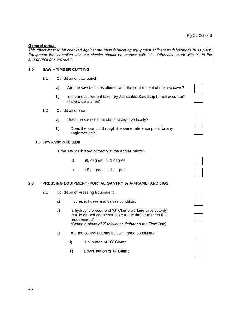
Pg CL 2/2 of 3
General notes: This checklist is to be checked against the truss fabricating equipment at licensed fabricator’s truss plant.
Equipment that complies with the checks should be marked with ‘ ‘. Otherwise mark with ‘X’ in the appropriate box provided.
1.0 SAW – TIMBER CUTTING
1.1 Condition of saw bench
a) Are the saw benches aligned with the centre point of the two saws? b) Is the measurement taken by Adjustable Saw Stop bench accurate?
(Tolerance 2mm)
1.2 Condition of saw
a) Does the saw-column stand straight vertically?
b) Does the saw cut through the same reference point for any angle setting?
1.3 Saw Angle calibration
Is the saw calibrated correctly at the angles below?
i) 90 degree 1 degree
ii) 45 degree 1 degree 2.0 PRESSING EQUIPMENT (PORTAL GANTRY or A-FRAME) AND JIGS
2.1 Condition of Pressing Equipment
a) Hydraulic hoses and valves condition. b) Is hydraulic pressure of ‘G’ Clamp working satisfactorily
to fully embed connector plate to the timber to meet the requirement? (Clamp a piece of 2” thickness timber on the Flow-Box)
c) Are the control buttons below in good condition?
i) ‘Up’ button of ‘G’ Clamp ii) Down’ button of ‘G’ Clamp
44
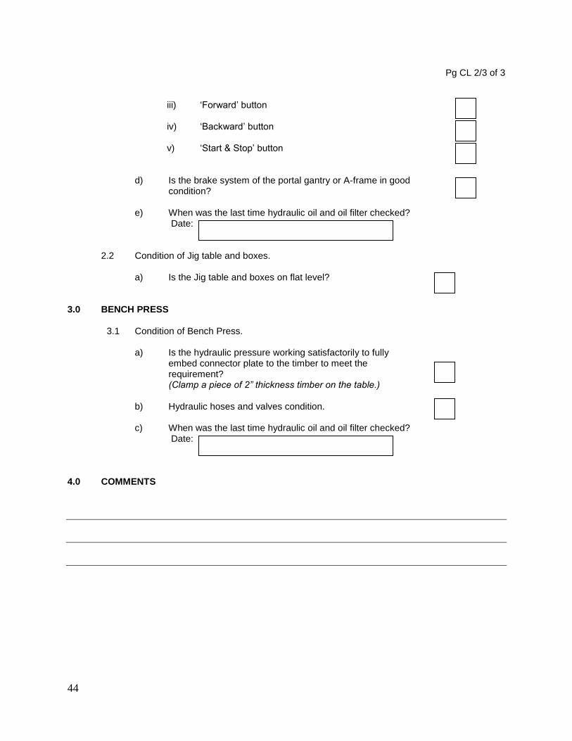
Pg CL 2/3 of 3
iii) ‘Forward’ button iv) ‘Backward’ button v) ‘Start & Stop’ button
d) Is the brake system of the portal gantry or A-frame in good
condition? e) When was the last time hydraulic oil and oil filter checked?
Date:
2.2 Condition of Jig table and boxes.
a) Is the Jig table and boxes on flat level? 3.0 BENCH PRESS
3.1 Condition of Bench Press.
a) Is the hydraulic pressure working satisfactorily to fully embed connector plate to the timber to meet the requirement? (Clamp a piece of 2” thickness timber on the table.)
b) Hydraulic hoses and valves condition. c) When was the last time hydraulic oil and oil filter checked?
Date:
4.0 COMMENTS
45
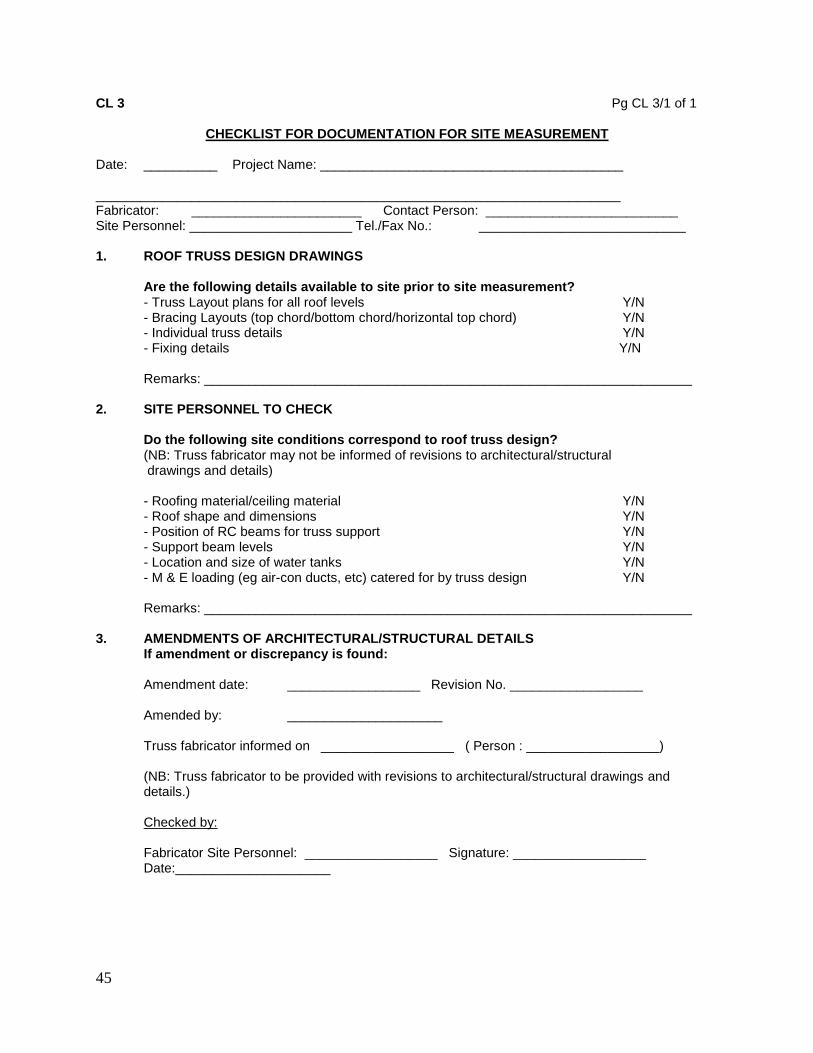
CL 3 Pg CL 3/1 of 1
CHECKLIST FOR DOCUMENTATION FOR SITE MEASUREMENT Date: __________ Project Name: _________________________________________ _______________________________________________________________________ Fabricator: _______________________ Contact Person: __________________________ Site Personnel: ______________________ Tel./Fax No.: ____________________________ 1. ROOF TRUSS DESIGN DRAWINGS
Are the following details available to site prior to site measurement? - Truss Layout plans for all roof levels Y/N - Bracing Layouts (top chord/bottom chord/horizontal top chord) Y/N - Individual truss details Y/N - Fixing details Y/N Remarks: __________________________________________________________________
2. SITE PERSONNEL TO CHECK
Do the following site conditions correspond to roof truss design? (NB: Truss fabricator may not be informed of revisions to architectural/structural drawings and details) - Roofing material/ceiling material Y/N - Roof shape and dimensions Y/N - Position of RC beams for truss support Y/N - Support beam levels Y/N - Location and size of water tanks Y/N - M & E loading (eg air-con ducts, etc) catered for by truss design Y/N Remarks: __________________________________________________________________
3. AMENDMENTS OF ARCHITECTURAL/STRUCTURAL DETAILS If amendment or discrepancy is found: Amendment date: __________________ Revision No. __________________
Amended by: _____________________ Truss fabricator informed on __________________ ( Person : __________________) (NB: Truss fabricator to be provided with revisions to architectural/structural drawings and details.) Checked by: Fabricator Site Personnel: __________________ Signature: __________________ Date:_____________________

46
CL 4 Pg CL 4/1 of 4
CHECKLIST FOR TIMBER AND TRUSSES AT TRUSS PLANT
Fabricator Name: _______________________________ Factory Location: _______________________________ Tel: _________________ _______________________________ Fax: _________________ Project Title: __________________________________________________ __________________________________________________ __________________________________________________ Block Checked: ______________________ Job No.: _______________ Factory Manager: ______________________ Quality Control Officer for Timber Selection & Sorting: _________________ Timber Sizing: ________________ Truss Assembly & Pressing: __________________ Timber Treatment : ___________
Date of Inspection: _______________________ Fabricator’s Representative (Name & Signature) : _______________________________________ A. RESULT OF TIMBER AND TRUSSES INSPECTION AT TRUSS PLANT This inspection on timber, timber preservative treatment and truss fabrication at the truss plant was commenced on _________________ and were found to: a) Conform to manufacturing specifications of the System Provider. Yes / No If ‘No’, b) The findings and rectifications or actions required are:
1. ______________________________________________________
2. ______________________________________________________
Verified by MTIB: __________________ Company Stamp : Signature: __________________________ Date: ___________________________

47
Pg CL 4/2 of 4
General note: This checklist is used to check trusses fabricated at a licensed fabricator’s truss plant.
1.0 TIMBER PRESERVATIVE TREATMENT
Instructions:
i) If checked parameter complies with specifications, mark with ‘ ‘. Otherwise mark with ‘X’ in the appropriate box provided. Comments to be noted in the Section 6.0 ‘REMARKS’ if appropriate.
1.1 Is timber treatment done within the plant?
1.2 If answer to above is ‘NO’.
- Are treatment certificates provided by supplier and done to specification? (Treatment Certificate)
1.3 If treatment is done within the plant.
- Is treatment certificate provided by fabricator and treatment done to specification? (Treatment Certificate)
GENERAL INSTRUCTIONS FOR SECTIONS 2.0, 3.0 AND 4.0: i.) Ten (10) trusses shall be randomly selected and individually checked against the truss design
drawings (Refer to Truss Design Drawings) for the parameters stated in Sections 2.0, 3.0 and 4.0 below.
ii.) Use separate page CL.4/4 for each individual truss selected to record results for Section 3.0 Truss Geometry and Section 4.0 Truss Quality Jointing Inspection checks.
iii.) For non-conformances, state the action or rectification needed.
2.0 TIMBER SIZE, GRADE, DEFECTS AND BOW INSPECTION
Instructions: 1.0 For each truss, check for defects in timber exceeding the limits stated in the MS1714 in terms of
‘Splits, Knots, Sloping grain, Borer holes, Bow etc.” 2.0 For each truss, randomly pick a minimum of one timber component for each cross-section size and
record its measurement.
2.1 What type of timber grading method used to grade timber?
Visual Grading Machine Grading
(Refer Attachment 3: Grading Summary)
2.2 Check on the selected timber component(s) of each individual truss selected for the
criteria in the following table.

48
Pg CL 4/3 of 4 Table 1: Measured sizes and presence of defects
Note: In the cross-section column states the various required nett design timber sizes for the selected trusses. Refer to Annex E and MS 1714 for defects identification 3.0 TRUSS GEOMETRY
Instructions: i) For each truss, sketch the overall truss profile on Pg CL4/4 and check the overall span and height
against the fabrication drawings.
4.0 TRUSS JOINTING QUALITY INSPECTION
Instructions: i) For both faces of each joint for each selected truss, record the connector sizes, positioning and
jointing quality in Pg CL4/4 of 4.
4.1 Inspect jointing quality of finished truss.
5.0 MARKING & STACKING OF FINISHED TRUSSES
5.1 Are finished trusses clearly and correctly marked? 5.2 Stacking of finished trusses :
a) Are trusses bundled off ground? (To avoid the trusses from being saturated specifically after raining)
b) Are trusses stacked correctly and supported sufficiently to avoid sagging?
6.0 REMARKS (if any) ___________________________________________________________________ ___________________________________________________________________
Pg CL 4/4 of 4
__x__ __x__ __x__ __x__
1
2
3
4
5
6
7
REMARKSTRUSS DEFECTS
CROSS-SECTION SIZE (mm x mm)

49
General note:Use ONE sheet of this page for EACH truss checked.
For Section 3.0. TRUSS GEOMETRY
REMARKS: _________________________________________________________________ ______________________________________________________________________ For Section 4.0 TRUSS JOINTING QUALITY INSPECTION (Check both faces of truss joints)
TRUSS PROFILE, MEMBER, AND JOINT NOS.
TRUSS MARK
TRUSS NO.
CHORD NO.
WEBS NO.
PROJECT:
DATA
JOINTS PLATE PLATE PLATE TIMBER JOINT JOINT
NOS. SIZES PLACEMENT PRESSING THICKNESS TIGHTNESS TYPE
1
2
3
4
5
6
7
8
9
10
11
12
13
14
15
16
17
18
19
20
REMARKSNO

50
CL 5. Pg CL 5/1 of 8
CHECKLIST FOR TRUSS INSTALLATION Fabricator Name: ____________________________________________________ Project Title: ____________________________________________________ ____________________________________________________ ____________________________________________________ Block Checked: ________________________ Job No.: ________________ Installer: ________________________ The final inspection is carried out in the presence of:
System Provider: __________________________________________________
Fabricator: __________________________________________________
Professional Engineer: __________________________________________________
Main Contractor’s Rep __________________________________________________
Consultant Engineer or S.O. Reps/JKR: ________________________________ Date of Inspection: ___________________ A. RESULT OF TRUSS INSTALLATION INSPECTION If any remedial work needs to be carried out, the proposed rectification is: 1. _________________________________________________________________________
2. _________________________________________________________________________
3. _________________________________________________________________________
4. _________________________________________________________________________ Approved By P.E.(Name): _______________________ Company Stamp Signature: __________________________ Date: _______________
OK NOT OK OK NOT OK
1 Wallplates 2 Trusses And Rafters 3 Bracing
Timber Bracing Steel Bracing
4 Other Framing Components Waling Plate Under-Purlins
5 Service Loads 6 Tile Battening (if applicable) 7 Purlins (if applicable) 8 Fascia Board
Materials Workmanship Remarks

51
Pg CL 5/2 of 8
General Instructions: i.) Use checklist in conjunction with truss layout and full set of truss designs (Refer to Design
Drawings).
ii.) Where brackets [ ] are provided, mark if acceptable, mark if rectification is required.
iii.) On truss layout plan, identify location of defect by putting a cross “” where it occurs, and describe defect by writing item number, e.g. 1.2(c) means starter bar not bent properly.
1. WALL-PLATES (extra care for roofs subject to high wind loading)
Specified size : _____________________ Grade specified : _____________________
No.
Location (or grid line)
Measured Size
Non-permissible
defects (Y/N)
Remarks
1
2
3
1.1 Materials:
a) No non-permissible timber defect between starter bar and truss [ ] b) Size of starter bar/anchor bolt matches specifications [ ]
1.2 Workmanship: a) Gaps between wall plate and beam at truss/rafter positions packed [ ] b) No knots at starter bar/anchor bolt positions [ ] c) Anchor bars bent sharply and secured at ends [ ] d) If applicable, washers provided for anchor bolts [ ] e) If applicable, anchor bolts tightened [ ] f) All wall plates anchored at minimum of 2 locations, or wall-plate with
one anchor joined to next piece with steel brace or timber block [ ] g) Wall-plate not notched for roofs subject to high wind loading [ ]
2. TRUSSES AND RAFTERS
2.1 Materials: a) Timber - defects within permissible limits* -
i) Knots [ ] iii) Checks and shakes (splits) [ ] ii) Wane [ ] iv) Fractures [ ]
* Refer to MS 544 Part 2 or Malaysian Grading Rules for Standard Structural or better grade
b) Truss joints-
i) Damage to connectors [ ] ii) Missing connectors [ ]
Pg CL 5/3 of 8 2.2 Workmanship:
All trusses visually checked for obvious misalignment and

52
incorrect spacing. Yes / No a) Spacing of trusses and rafters [ ]
(Specified truss spacing : _____________ mm)
Measurement of Truss-to-Truss Spacing (Tolerance +50mm)
Truss No.
Truss-to-truss spacing Remarks To the left To the right
b) Vertical alignment (misalignment < height/50 or max. 50mm) [ ] c) Horizontal alignment (misalignment < span/200 or max. 50mm) [ ]
Measurement of Vertical and Horizontal Misalignment
Truss Mark :
Truss Profile (indicate positions where vertical (V) and horizontal (H) alignment measurements are taken)
Truss Span :
Max. Truss Ht :
Vertical alignment tolerance( max. ht / 50 or 50 mm whichever is less) :
Horizontal alignment tolerance( Span / 200 or 50mm, whichever is less) :
Truss No.
Vertical Alignment at Position
Horizontal Alignment at Position
Remarks
V1 V2 V3 H1 H2 H3
1
2
3
4
5
6
7
8
Pg CL 5/4 of 8 d) Internal supports provided at correct locations as designed [ ]
53
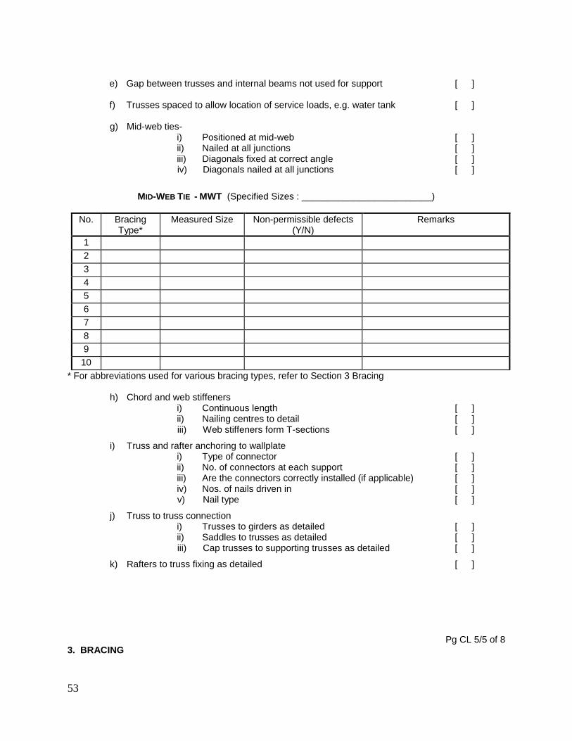
e) Gap between trusses and internal beams not used for support [ ] f) Trusses spaced to allow location of service loads, e.g. water tank [ ] g) Mid-web ties-
i) Positioned at mid-web [ ] ii) Nailed at all junctions [ ] iii) Diagonals fixed at correct angle [ ] iv) Diagonals nailed at all junctions [ ]
MID-WEB TIE - MWT (Specified Sizes : _________________________)
No. Bracing Type*
Measured Size Non-permissible defects (Y/N)
Remarks
1
2
3
4
5
6
7
8
9
10
* For abbreviations used for various bracing types, refer to Section 3 Bracing
h) Chord and web stiffeners i) Continuous length [ ] ii) Nailing centres to detail [ ] iii) Web stiffeners form T-sections [ ]
i) Truss and rafter anchoring to wallplate i) Type of connector [ ] ii) No. of connectors at each support [ ] iii) Are the connectors correctly installed (if applicable) [ ] iv) Nos. of nails driven in [ ] v) Nail type [ ]
j) Truss to truss connection i) Trusses to girders as detailed [ ] ii) Saddles to trusses as detailed [ ] iii) Cap trusses to supporting trusses as detailed [ ]
k) Rafters to truss fixing as detailed [ ]
Pg CL 5/5 of 8 3. BRACING

54
Specified Sizes : _______________________________________________
No. Bracing Type*
Measured Size Non-permissible defects (Y/N)
Remarks
1
2
3
4
5
6
7
8
*Abbreviations used for bracing types :
Top Chord Bracing - tcb Bottom Chord Tie - bct
Bottom Chord Bracing - bcb Diagonal brace - db
3.1 Materials of correct size and type [ ]
3.2 Workmanship (timber bracing) a) Diagonal bracing provided for positional stability [ ] b) Bracing nailed at all junctions [ ] c) Bracing spliced according to specifications [ ] d) Bracing finished at wall plate according to specifications [ ] e) Bracing detail at cantilever [ ] f) Bracing angles [ ] g) Bracing lay-out [ ] h) For multilevel trusses, horizontal top chords of supporting trusses laterally tied and braced [ ]
3.3 Workmanship (steel brace) a) Bracing layout and position [ ] b) End fixing detail at heel [ ] c) End fixing at apex [ ] d) Bracing splicing detail [ ] e) Bracing tightness [ ] f) Nail type and size [ ]
4. OTHER FRAMING COMPONENTS
4.1 Waling plate a) Material [ ] b) Fixing detail [ ]
4.2 Under-purlins a) Material [ ] b) Fixing detail [ ]
Pg CL 5/6 of 8
55
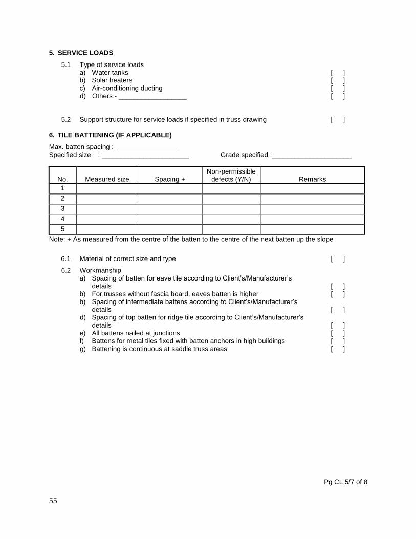
5. SERVICE LOADS
5.1 Type of service loads a) Water tanks [ ] b) Solar heaters [ ] c) Air-conditioning ducting [ ] d) Others - __________________ [ ]
5.2 Support structure for service loads if specified in truss drawing [ ]
6. TILE BATTENING (IF APPLICABLE)
Max. batten spacing : _________________ Specified size : _______________________ Grade specified :_____________________
No.
Measured size
Spacing +
Non-permissible defects (Y/N)
Remarks
1
2
3
4
5
Note: + As measured from the centre of the batten to the centre of the next batten up the slope
6.1 Material of correct size and type [ ]
6.2 Workmanship a) Spacing of batten for eave tile according to Client’s/Manufacturer’s
details [ ] b) For trusses without fascia board, eaves batten is higher [ ] b) Spacing of intermediate battens according to Client’s/Manufacturer’s
details [ ] d) Spacing of top batten for ridge tile according to Client’s/Manufacturer’s
details [ ] e) All battens nailed at junctions [ ] f) Battens for metal tiles fixed with batten anchors in high buildings [ ] g) Battening is continuous at saddle truss areas [ ]
Pg CL 5/7 of 8

56
7. PURLINS (IF APPLICABLE)
Max. purlin spacing : _________________ Specified size : ____________________ Grade specified : __________________
No.
Measured size
Spacing +
Non-permissible defects (Y/N)
Remarks
1
2
3
4
5
Note” + As measured from the centre of the purlin to the centre of the next purlin up the slope
7.1 Material of correct size and type [ ]
7.2 Workmanship a) Top purlin spaced to suit fixing of ridge piece [ ] b) Intermediate purlins spaced-
i) Within Manufacturer’s limit [ ] ii) To suit multiple sheets [ ] iii) To allow for end laps of multiple sheets [ ]
c) Purlins fixed with purlin anchors according to detail [ ] d) Orientation of purlins according to design detail [ ]
8. TIMBER FASCIA BOARD
Specified size (by fabricator) : _____________________
No.
Location (or grid line)
Measured size
Non-permissible defects (Y/N)
Remarks
8.1 Material of correct size and type [ ]
8.2 Workmanship a) For concrete/clay tile roofs, fascia board positioned above batten line
for eaves tile [ ] b) Fascia board spliced at correct positions [ ] c) Horizontal alignment of fascia board [ ] d) Edge of eaves tile is in line with axis of storm gutter [ ]
Pg CL 5/8 of 8

57
9. SKETCHES (note any damage caused by other sub-contractors):
I.
II.
III.
IV.

58
ANNEX E (normative)
MS 544: PART 2: 2001 CODE OF PRACTICE FOR STRUCTURAL USE OF TIMBER PART 2 : PERMISSIBLE STRESS DESIGN OF SOLID TIMBER
Appendix C. Grading of Malaysian structural timbers

59
Appendix E
GRADING OF MALAYSIAN STRUCTURAL TIMBERS
E1. Grade The timber should be graded, by assessing the characteristics covered by Clauses E1 to E11 inclusive on each piece, in the size and condition in which it is used, into the following grades: a) select structural; b) standard structural; and c) common building The grades are multipurpose grades, i.e. applicable to all structural timbers whether used as bending members, or in endwise compression. In the case of timber used as beams, the recommended working stresses (as given in Clause 6 Design considerations of MS 544 : Part 1) will apply no matter which way up the members intended for resawing to shorter lengths. The standard structural grade should be specified for normal purposes. The select structural grade is intended for special purposes, particularly when the strength/weight ratio of the timber is to be a maximum, for example in towers for transmission lines and trusses of very long span. The common building grade is intended for wooden members used in less important parts of building frames, which are not usually designed by means of engineering calculations. E2. Open shakes, surfaces checks and end checks E2.1 Measurement The size of an open shake or surface check should be taken as its depth projected into a surface at right angles to the face on which it occurs. The projected depths of all checks occurring within the middle half of the face should be added together to assess the magnitude of the total defect. A feeler gauge of 0.13 mm thickness should be used in measuring the size of an open shake or surface check. E2.2 Grading limits To qualify for a particular grade, a member should not have shakes or checks whose size, expressed as a fraction of the width of the face at right angles to the one on which the defects occur, exceeds the maximum value given in Table E1.
Table E1. Maximum size of shakes and checks
Grade Maximum permissible limit
Select
Standard
Common
1/6 thickness
1/3 thickness
1/2 thickness

60
E3. Slope of grain E3.1 Measurement The slope of grain should be measured over a distance sufficiently great to determine the general slope, disregarding slight local deviations (round small knots, etc.). The minimum distance over which the slope of grain is measured should not ordinarily be less than the distance over which a deviation of 25 mm is permitted, e.g. a slop of 1 in 15 should be measured over distance of not less than 375mm if possible. A cranked scribe with a freely swiveling handle should be used. The slope of grain shall be measured on the face or edge where it is most severe (see E12). E3.2 Grading limits To qualify for a particular grade, a member should not have a slope of grain steeper than the value given in Table E2.
Table E2. Maximum slope of grain
Grade Maximum slope of grain
Select
Standard
Common
1 in 16
1 in 10.7
1 in 8
E4. Spiral grain Where spiral grain occurs, the slope of grain should be determined by measuring the worst slope of grain on the faces and edges and taking the square root of the sum of the square of the slopes. For example if these slope are 1 in 18 and 1 in 12, the combined slope is:
or a slope of 1 in 10
NOTE. This procedure is intended to apply where it is deemed necessary to measure the slope of grain in most cases, it will be sufficient for the grader to use his judgement in rejecting timber containing spiral grain to an undesirable extent.
E5. Wane E5.1 Measurement The amount of wane on any surface should be the sum of the wane at the two arises, and should be expressed as a fraction of the width of the surface on which it occurs (see Figure E1).
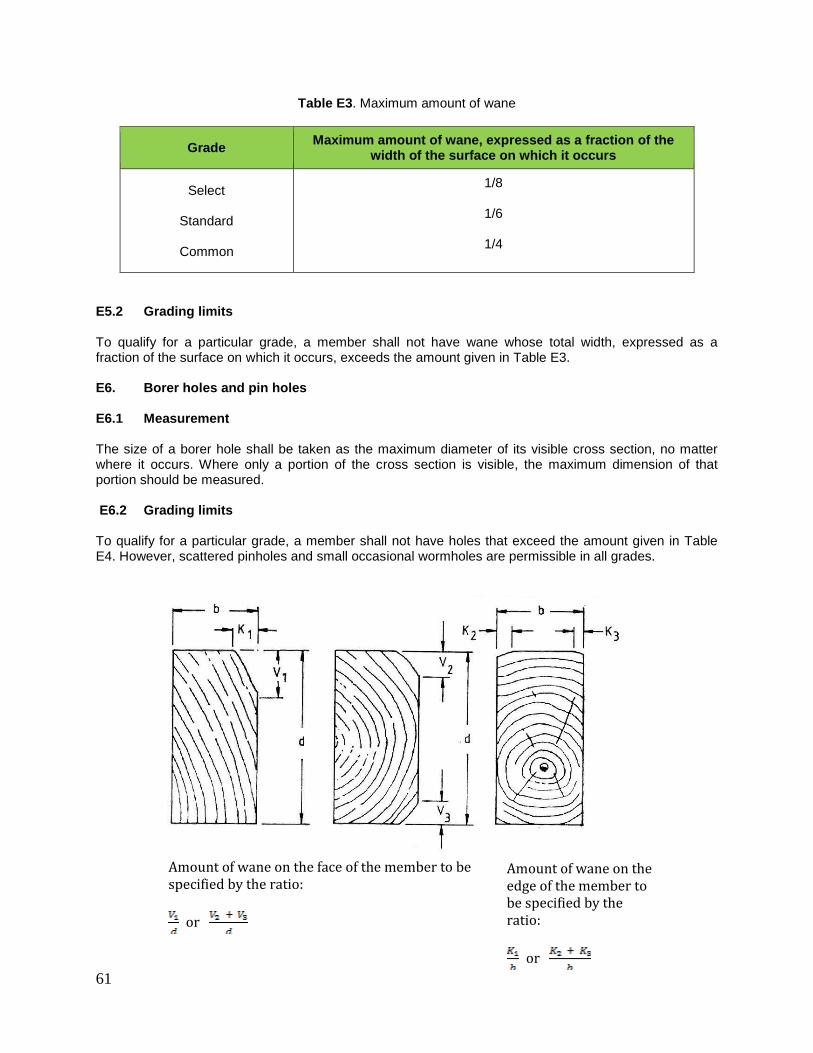
61
Table E3. Maximum amount of wane
Grade Maximum amount of wane, expressed as a fraction of the
width of the surface on which it occurs
Select
Standard
Common
1/8
1/6
1/4
E5.2 Grading limits To qualify for a particular grade, a member shall not have wane whose total width, expressed as a fraction of the surface on which it occurs, exceeds the amount given in Table E3. E6. Borer holes and pin holes E6.1 Measurement The size of a borer hole shall be taken as the maximum diameter of its visible cross section, no matter where it occurs. Where only a portion of the cross section is visible, the maximum dimension of that portion should be measured. E6.2 Grading limits To qualify for a particular grade, a member shall not have holes that exceed the amount given in Table E4. However, scattered pinholes and small occasional wormholes are permissible in all grades.
Amount of wane on the face of the member to be specified by the ratio:
or
Amount of wane on the edge of the member to be specified by the ratio:
or
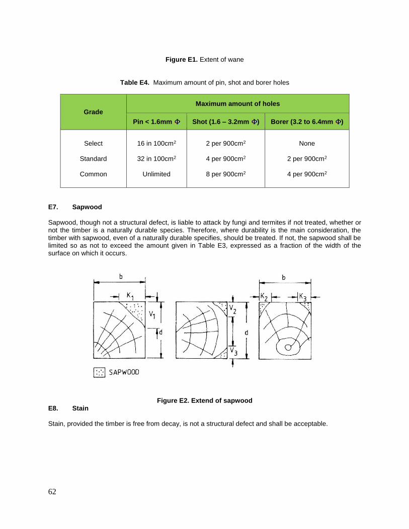
62
Figure E1. Extent of wane
Table E4. Maximum amount of pin, shot and borer holes
Grade
Maximum amount of holes
Pin < 1.6mm Shot (1.6 – 3.2mm ) Borer (3.2 to 6.4mm )
Select
Standard
Common
16 in 100cm2
32 in 100cm2
Unlimited
2 per 900cm2
4 per 900cm2
8 per 900cm2
None
2 per 900cm2
4 per 900cm2
E7. Sapwood Sapwood, though not a structural defect, is liable to attack by fungi and termites if not treated, whether or not the timber is a naturally durable species. Therefore, where durability is the main consideration, the timber with sapwood, even of a naturally durable specifies, should be treated. If not, the sapwood shall be limited so as not to exceed the amount given in Table E3, expressed as a fraction of the width of the surface on which it occurs.
Figure E2. Extend of sapwood E8. Stain Stain, provided the timber is free from decay, is not a structural defect and shall be acceptable.

63
E9. Curvature E9.1 Measurement The extent of curvature is determined by measuring the maximum deviation from a tightly stretched string or wire, expressed as a ratio of the length of the timber. E9.2 Grading limits To qualify for a particular grade, a member shall not have curvature whose deviation exceeds the amount given in Table E5.
Table E5. Maximum amount of curvature
Grade Maximum slope of grain
Select
Standard
Common
5 mm in 3 m
10 mm in 3 m
15 mm in 3 m
Table C6 shows permissible deviations in curvature for some common lengths.
Table E6. Permissible deviations in curvature
Length of timber, m
Permissible deviations (mm)
Select grade (5mm in 3m)
Standard grade (10mm in 3m)
Common grade (10mm in 3m)
2 3 7 10
3 5 10 15
` 7 13 20
5 8 17 25
6 10 20 30
7 12 23 35
8 13 27 40
E10. Knots E10.1 Measurement The size of a knot shall be taken as the maximum diameter of its visible cross section, no matter where it occurs. Where the knot can be seen in longitudinal section as well as in cross section, the longitudinal section should be ignored. Where two or more knots occur in the same cross section, each knot should be measured as just described and the sum of these measurements taken as a diameter of an equivalent single knot.

64
E10.2 Grading limits To qualify for a particular grade, a member shall not have knots whose sizes exceed the maximum values given in Tables C7 and C8. E11. Other defects All pieces showing fungal decay, brittleheart or other abnormal defects affecting strength shall be excluded from all grades, except in pieces of standard structural and common building grades that have unsound or hollow knots which contain fungal decay. In such cases the permissible size of unsound knots for the respective grades are as shown in Table 8.
Table E7. Maximum width of permissible sound knots
Grade Maximum width of knots
Select dimension of face, to maximum of 38mm in diameter. 1 per 1mm in length
Standard dimension of face, to maximum of 75mm in diameter. 1 per 1mm in length
Common dimension of face, to maximum of 100mm in diameter. 1 per 1mm in length
Table E8. Maximum width of permissible unsound knots
Grade Maximum width of knots
Select None
Standard dimension of face, to maximum of 50mm in diameter. 1 per 2.4mm in length
Common dimension of face, to maximum of 75mm in diameter. 1 per 1mm in length
E12. Guided to the determination of slope of grain To ascertain the slope of the grain in timber it is necessary to study both the quartered and flat-sawn faces of the member. If seasoning checks are present, these will indicate the slope of the grain. Slope of grain can be more accurately determined by means of a scribe, as shown in Figure C3 comprising a cranked rod with a swivel handle and a needle, similar to a gramophone needle, at the tip, set to a slight trailing angle. The needle is pressed into the wood and the scribe is drawn along with a steady action in the apparent dissection of the grain, which is indicated more precisely as the needle forms a groove. If the pressure on the needles is insufficient it may be dragged across the grain: on the other hand, a steady action is impossible if the pressure is excessive and the needle penetrates too far into the wood. If the action is correcting the needle follows the grain even when the direction of pull of the scribe is slightly out of line. This may be used to check that the scribe does follow the grain by scribing another groove in close proximity on each side of the original one with direction of pull diverging slightly outwards in each case when, if the grooves are following the grain, they will be parallel to each other.
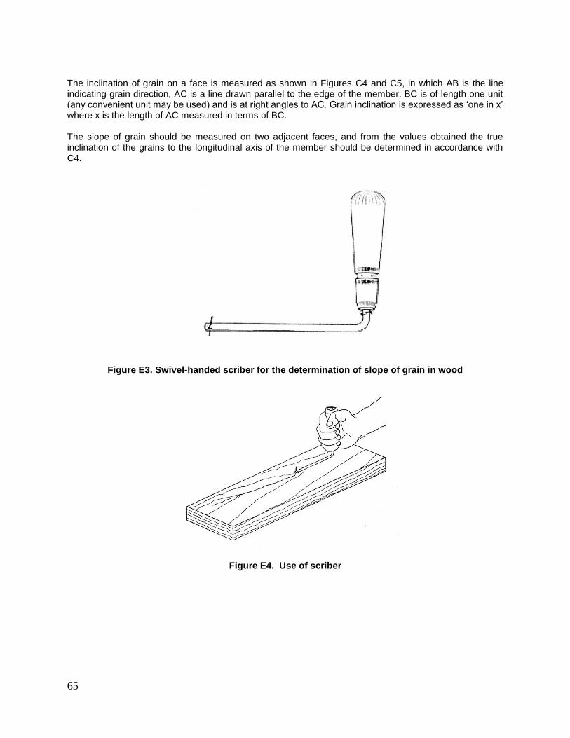
65
The inclination of grain on a face is measured as shown in Figures C4 and C5, in which AB is the line indicating grain direction, AC is a line drawn parallel to the edge of the member, BC is of length one unit (any convenient unit may be used) and is at right angles to AC. Grain inclination is expressed as ‘one in x’ where x is the length of AC measured in terms of BC. The slope of grain should be measured on two adjacent faces, and from the values obtained the true inclination of the grains to the longitudinal axis of the member should be determined in accordance with C4.
Figure E3. Swivel-handed scriber for the determination of slope of grain in wood
Figure E4. Use of scriber
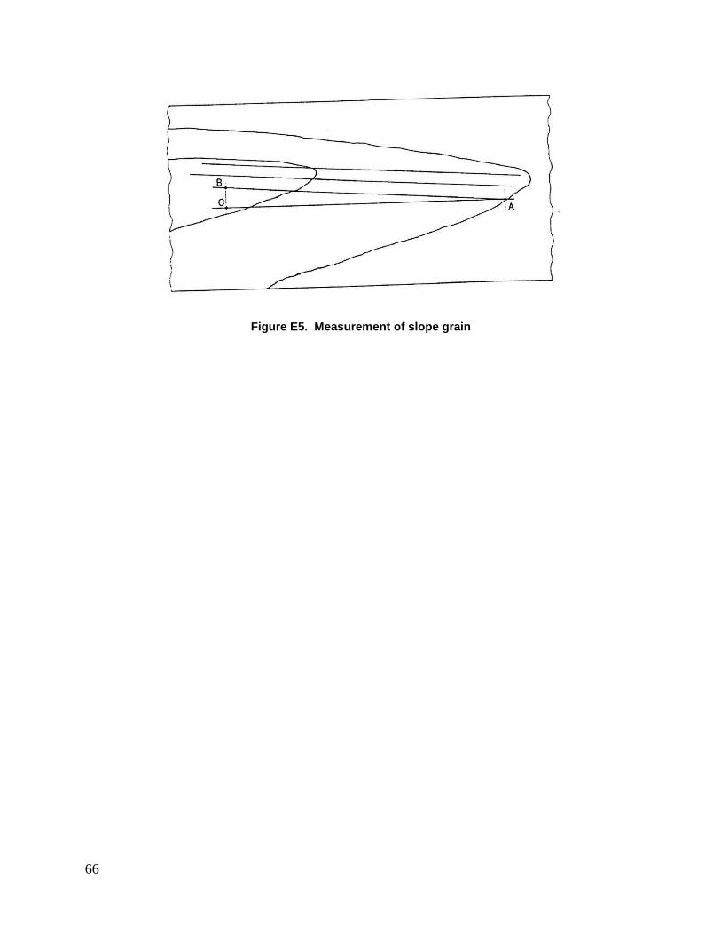
66
Figure E5. Measurement of slope grain

67
ANNEX F (normative)
MS544: 1978 TABLE A1. CLASSIFICATION OF TIMBERS INTO SHRINKAGE GROUPS
Table A1. Classification of timbers into shrinkage groups (based on average tangential shrinkage from green to 19 per cent moisture content)
Group 1
0.5 to 1.5 per cent inclusive
Group 2 Over 1.5 to 2.5 per cent
Group 3 Over 2.5 to 3.5 per cent
Group 4 Over 3.5 to 5 per cent
Group 5 Over 5 per cent
CHENGAL* (Balanocarpus heimi - King) DAMAR MINYAK* (Agathis alba) JELUTONG* (Dyer a costulata - Hook. f.) KELEDANG* (Artocarpus lanceifolius - Roxb. (A.rigidus) KUNGKUR* (Pithecellobium confertum) MACHANG* (Mangifera longipes) (M. indica) (M. foetida Lour.)
BINTANGOR* (Calopyllum inophyllum) (C.kunstleri) (C.curtisii) GIAM* (Hopea helferi (Dyer, Brandis) (H. nutans - Ridl.) KERANJI* (Dialium Platysepalum Baker) MEDANG* (Litsea megacapa) (L. firma) MEMPISANG* (Cathocalyx maingayi) MERANTI, DARK RED* (Shoreabracteolata Dyer)
BALAU* (Shorea laevis Ridl.) (S. maxwelliana King) (S. glauca - King) BALAU, RED* (Shorea guiso (Blanco) Bl.) (S. kunstleri - King) (S. ochroploia) BITIS* (Madhuca utilis Ridl.) (H.J. Lam) DURIAN* (Durio oxleyanus) KEDONGONG* (Canarium rufum) (Santiria laevigata - Bl.) KEKATONG* (Cynometra inaequifolia A. Gray)
GERONGGANG* (Cratoxylon spp.) KAPUR* (Dryobalanops aromatica - Gaertn.) (D. oblongifolia) KERUING* (Dipterocarpus baudii - Korth) (D. cornutus Dyer) (D. costulatus van sloot) (D. crinitus) (D. lowii) MEMPENING (Quercus lamponga)) MEMPISANG* (Mezzittia leptopoda Oliv.) MERANTI, DARK RED* (Shorea platyclados)
KERUING* (Dipterocarpus Gramdoflorus) MERANTI BAKAU* (Shorea rugosa var. uliginosa) PUNAH* (Tetramerista glabra)
*Timbers that appear in the Malayan Grading Rules

68
Table A1. Continued
Group 1 0.5 to 1.5 per cent inclusive
Group 2 Over 1.5 to 2.5 per cent
Group 3 Over 2.5 to 3.5 per cent
Group 4 Over 3.5 to 5 per cent
Group 5
Over 5 per cent
MEDANG* (Dehaasia nigrescens)
MERANTI, WHITE* (Shorea talura) MERBAU* (Intsia palembanica Baker) MERPAUH* (Swintonia schwenkii) (S. spicifera Hook.f.) (S.penangiana) RENGAS* (Melanorrhoea torquota) SEPETIR* (Sindora coriacea Prain) SESENDOK* (Endospermum malaccense Muell. -Arg.) TUALANG* (Koompassia excelsa - Taub.)
MERANTI, LIGHT RED* (Shorea hemsleyana
King) MERANTI, WHITE* (Shorea bracteolata Dyer) MERAWAN* (Hopea sulcata) PERUPOK* (Lophopetalum reflexum) (L. Maingayi Ridl.) (L. floribundum) (L. subovatumKing) PULAI* (Alstonia angustiloba) TABAN MERAH (Palaquinumgutta) TEMBUSU* (Fragraea FragransRoxb.)
KEMPAS* (Koompassia malaccensis Maing.) KULIM* (Scorodocarpus borneersis - Becc.) MELUNAK* (Pentace triptera - Mast) MENGKULANG* (Heritiera javanica Bl.) (H. simplicifolia Mast.) MERANTI, DARK RED* (Shorea pauciflora King) MERANTI, WHITE* (Shorea hypochra Hance) MERANTI, YELLOW* (Shorea resinanigra Foxw.) MERAWAN* (Hopea nervosa King) MERTAS (Ctenolophon parvifolius) MINYAK BEROK (Xanthophyllum verrucosum) PENARAHAN* (Myristica gigantea) (M.maingayi)
PENAGA (Mesua ferrea) RAMIN (MELAWIS)* (Gonystylus bancanus (Miq.) Baill.)
MERANTI, LIGHT RED* (Shorea parvifolia Dyer) MERANTI, LIGHT RED* (Shorea leprosula Miq.) (Shorea acuminata - Dyer) MERSAWA* (Anisoptera spp.) NYALAS* (Parastemon urophyllum) SIMPOH* (Dillenia grandifolia) TERAP* (Parartocarpus triandra) TERENTANG* (Campnosperma Macrophylla)

69
RESAK* (Vatica cuspidata (Ridl.) Sym.) TERAP* (Artocarpus Scortechnii Hook.f.) TERENTANG* (Campuosperma Auriculata Hook.f.)
*Timbers that appear in the Malayan Grading Rules

70
ANNEX G
(informative)
TERMS APPLYING TO PREFABRICATED TIMBER ROOF TRUSSES
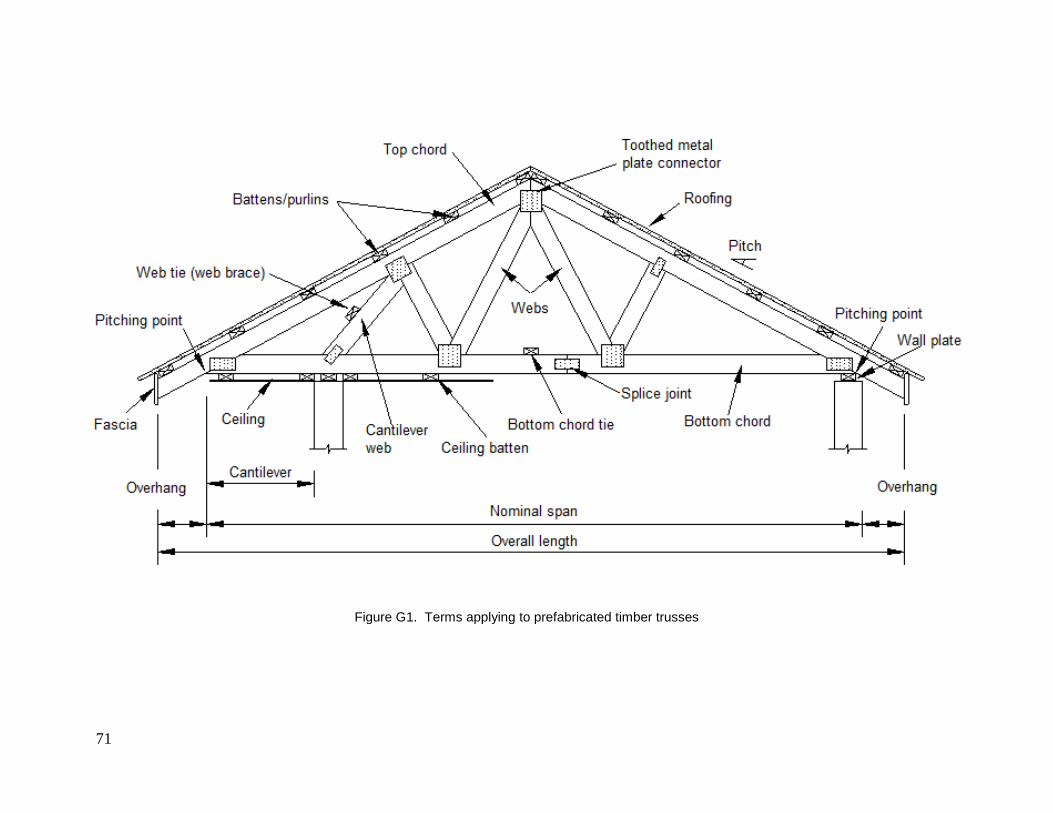
71
Figure G1. Terms applying to prefabricated timber trusses
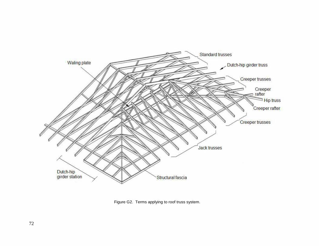
72
Figure G2. Terms applying to roof truss system.

73
ANNEX H
(informative)
Some Examples of Truss Fabrication Defects Involving the Toothed Metal Plate (Nail Plate)
Connectors
Terms applied to roof truss system
a)
b)
c)
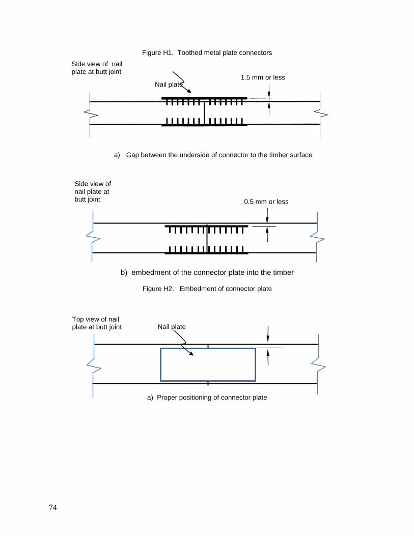
74
Figure H1. Toothed metal plate connectors
a) Gap between the underside of connector to the timber surface
b) embedment of the connector plate into the timber
Figure H2. Embedment of connector plate
a) Proper positioning of connector plate
Side view of nail plate at butt joint
Side view of nail plate at butt joint
Top view of nail plate at butt joint
1.5 mm or less
0.5 mm or less
Nail plate
Nail plate

75
b) Mispositioning of connector plate across the width of timber
c) Mispositioning of connector plate along the length of timber
Note: Mispositioning of connector by not more than 6mm for connector dimension of less than 150mm (in the direction
of the dimension), and, 12mm for connector dimension of 150mm or more (in the direction of the dimension).
Figure H3. Positioning of toothed metal plate connectors.
Figure H4. Side view of a butt joint: acceptable placement of nail plates
(teeth are not bent or flattened)
Top view of nail plate at butt joint
Top view of nail plate at butt joint
Part of connector projects outside the timber edge
Misposition
Misposition
Side view of nail plates at butt joint
Nail plate

76
(a)
(b)
Figure H5. Side view of a butt joint: Teeth roll or roll-over (teeth bent or flattened)
a) Case 1
b) Case 2
Figure H6. Vertical gaps.
Nail plate moves during pressing
Nail plate moves during pressing
High density timber Very high density timber
Side view of nail plates at butt joint
Side view of nail plates at butt joint
Top view of nail plate at butt joint
Gap
Gap
Nail plate
Nail plate with teeth either bent or flatened
Side view of nail plates at butt joint
Gap

77
Figure H7. Horizontal gap in built-up structural members
a) Case 1
b) Case 2
Figure H8. Mismatch timbers
Side view of nail plates at butt joint
Side view of nail plates at butt joint
Edge joint
End joint
Gap
Top view of nail plates at edge and end jointed components
Nail platxe

78
REFERENCES
Standards Australia International Ltd. AS 4440-2004 Installation of Nailplated Timber Roof Trusses. Sydney: Standard Australia International Ltd.; 2004. European Committee for Standiardization. BS EN 1991-1-1:2002 Eurocode 1. Action on Structure. General Actions. Densities, Self-weight Imposed Loads for Buildings. Brussels; 2002. BS EN 1991-1-7:2006+A1:2014 Eurocode 1. Actions on Structure. General Actions. Accidental Actions. Brussles; 2006.

79
AKNOWLEDGMENT This Malaysian Construction Industry Standard is a revision of the CIS 5:2004. The committee involved in the revision consists of the following representatives: Tn. Hj. Sazali Che Amat Construction Industry Development Board Malaysia Nur Hanis Amsari Rashimah Adenan Ahmad Nuhairi Haji Abdul Razak Ramlan Bidin Md Zahari Abdul Rahman Ir. Pof. Dr. Mohd Zamin Bin Jumaat Board of Engineers Malaysia Datin Salamah Selamat Forest Research Institute Malaysia Zainuddin Mohd Damin Haustek Engineering Sdn. Bhd. Tn. Hj. Ahmad Rosli Abd Rahman Jabatan Kerja Raya Megat Kamarulzaman Megat Yusoff Mohd Khairi Yaacob Dr. Mohd Norzamri Mat Amin Malaysian Timber Industry Board Dr. Yeoh Beng Hoong Hajah Mahsuri Mat Dris Nor Liza Mat Yasok Wan Suhaimi Wan Chek Ng Wun Pin Multinail Asia Sdn Bhd Ahmad Zabidi Abdul Rashid Persatuan Pengusaha Kayu-Kayan dan Perabot
Bumiputra Malaysia Ar. Mariyah binti Pit Pertubuhan Akitek Malaysia Prof. Dr. Badorul Hisham Abu Bakar Universiti Sains Malaysia Dr. Mustafasanie M. Yussof Prof. Madya Dr. Mohd Ariff Jamaludin Universiti Teknologi Mara (Chairman)
Related Documents