STANDARD BIDDING DOCUMENT FOR PROCUREMENT OF WORKS Augmentation and Rehabilitation of Water Supply and Sewerage System Package – 1 Water Supply Pipeline and Sewerage Network System at Patiala Town, (District Patiala) (Under AMRUT) (Value of the Project Rs 1752.48 lakh) Volume -2 SECTION-5 TECHNICAL CONDITIONS, SPECIFICATIONS & REQUIREMENTS Standard Basic Specifications & General Requirement April, 2018

Welcome message from author
This document is posted to help you gain knowledge. Please leave a comment to let me know what you think about it! Share it to your friends and learn new things together.
Transcript
STANDARD BIDDING DOCUMENT FOR PROCUREMENT OF WORKS
Augmentation and Rehabilitation of
Water Supply and Sewerage System
Package – 1
Water Supply Pipeline and Sewerage Network System
at
Patiala Town, (District Patiala)
(Under AMRUT)
(Value of the Project Rs 1752.48 lakh)
Volume -2
SECTION-5
TECHNICAL CONDITIONS, SPECIFICATIONS & REQUIREMENTS
Standard Basic Specifications & General Requirement
April, 2018

Patiala Town Under AMRUT Scheme
Section-5 Volume -2 Package-1
Water Supply Pipeline and Sewerage Network System
Standard Basic Specifications & General Requirement Technical Conditions, Specifications & Requirements
2
Contractor:
Date:
Executive Engineer:
Date:
CONTENTS A. INTRODUCTION 5
B. WATER SUPPLY SYSTEM 6
C. SCOPE OF WORK 6
1. DISTRIBUTION SYSTEM AND RISING MAIN 6
2. FIRE HYDRANTS 6
3. SLUICE VALVE 7
4. AIR VALVES 7
5. RE-SURVEY OF PROPOSED WATER DISTRIBUTION SYSTEM 7
6. DEMARCATION OF EXTENSION AREAS 7
7. MAKING ROAD MOTOR-ABLE 7
8. RESTORATION OF ROADS 8
D. SPECIFICATIONS 8
1. SPECIFICATION FOR DUCTILE IRON PIPES 8
2. QUALITY ASSURANCE PROTOCOL (DI PIPES) - QUALITY ASSURANCE STEPS TO BE TAKEN
AT SITE 13
3. DI FITTINGS & SPECIALS 16
4. JOINTS BETWEEN PIPE AND FITTINGS 19
5. TYPE TESTS 19
6. LAYING AND JOINTING OF DI PIPES 21
7. G.I PIPES 25
8. SPECIFICATION FOR CI DOUBLE FLANGED SLUICE VALVES 26
9. SPECIFICATION FOR CI SURFACE BOXES FOR SLUICE VALVES 26
10. CI/DI FITTINGS FOR CI/DI PRESSURE PIPES FOR WATER 26
11. UNDERGROUND FIRE HYDRANT, SLUICE VALVE TYPE (WITH ROAD SURFACE BOX) 26
12. SPECIFICATION FOR INDICATING PLATE FOR FIRE HYDRANT AND SLUICE VALVES 27
13. SPECIFICATION FOR CI SPUN PRESSURE PIPES FOR WATER 27

Patiala Town Under AMRUT Scheme
Section-5 Volume -2 Package-1
Water Supply Pipeline and Sewerage Network System
Standard Basic Specifications & General Requirement Technical Conditions, Specifications & Requirements
3
Contractor:
Date:
Executive Engineer:
Date:
14. HORIZONTAL CAST IRON PRESSURE PIPES 28
15. VERTICALLY CAST IRON PRESSURE PIPES FOR WATER 28
16. SPECIFICATION FOR SPUN HEMP YARN 28
17. SPECIFICATION FOR PIG LEAD 28
18. SPECIFICATIONS FOR PLASTIC FOOT STEP 29
19. INSPECTION OF MATERIAL 29
E. SEWERAGE SYSTEM 30
1. EXISTING SEWERAGE SYSTEM 30
2. SCOPE OF WORK 31
3. SPECIFICATIONS OF MATERIALS 34
4. QUALITY ASSURANCE PROTOCOL FOR U-PVC PIPES 34
5. QUALITY ASSURANCE STEPS TO BE TAKEN AT SITE 37
6. QUALITY ASSURANCE PROTOCOL HDPE T-GRIP FOR LINING FOR RCC PIPES 41
7. DESIGN CRITERIA 46
F. STANDARD BASIC SPECIFICATION 48
1. GENERAL 48
2. EARTH WORK 50
3. DRAINAGE IN THE VICINITY OF EXCAVATION 52
4. EXCAVATION IN TRENCHES AND CABLE DUCTS 53
5. BACK FILLING / EARTH FILLING 54
6. FILLING AND EMBANKMENT 55
7. SHORING/STRUTTING/TIMBERING 56
8. QUALITY ASSURANCE 57
9. SAFETY PLAN 57
10. ENVIRONMENTAL QUALITY MANAGEMENT PLAN 58
11. TOPOGRAPHICAL SURVEY AND SOIL INVESTIGATION AGENCY 58
12. FIELD OFFICES 58
13. FACILITIES TO BE PROVIDED FOR THE ENGINEER, HIS REPRESENTATIVES & CONSULTANTS
58

Patiala Town Under AMRUT Scheme
Section-5 Volume -2 Package-1
Water Supply Pipeline and Sewerage Network System
Standard Basic Specifications & General Requirement Technical Conditions, Specifications & Requirements
4
Contractor:
Date:
Executive Engineer:
Date:
14. CEMENT SPECIFICATIONS 58
15. STEEL BARS FOR CONCRETE REINFORCEMENT 60
16. SAMPLES AND TESTS OF MATERIALS 60
G. GENERAL CONDITIONS 61
1. GENERAL 61
2. QUALITY CONTROL 62
3. QUALITY ASSURANCE 64
4. BUILDING WORKS 64
5. LIST OF MANDATORY TESTS 65
6. INSPECTION OF WORKS 66
7. WORK TO BE EXECUTED IN ACCORDANCE WITH SPECIFICATIONS DRAWINGS & ORDER 66
8. PREAMBLE TO BILL OF QUANTITIES (CIVIL PORTION) 66
9. LIST OF INDIAN STANDARDS 67

Patiala Town Under AMRUT Scheme
Section-5 Volume -2 Package-1
Water Supply Pipeline and Sewerage Network System
Standard Basic Specifications & General Requirement Technical Conditions, Specifications & Requirements
5
Contractor:
Date:
Executive Engineer:
Date:
Name of work:
Package – 1
Water Supply Pipeline and Sewerage Network System
(a) Providing, laying, jointing, cutting, testing and commissioning the
work of DI Pipe ISI marked for Distribution system, Rising (Pumping)
Main Pipeline;
(b) Providing, laying, jointing , testing and commissioning work of Lateral
Sewers of ISI marked U-PVC SN8 Non-Pressure Pipe as per
IS:15328- latest and main sewers of RCC pipe Class NP-3 (IS:458-
latest) with HDPE lining and refilling trench, consolidating,
construction of Brick Manholes Chambers, House Connections and
IC;
(c) Dismantling of Roads for House Service Connection (HSC) and
pipeline for water Supply and Sewerage system and refilling trench,
consolidating and making road motor-able using serviceable material
and dismantling & restoration of road Works of Concrete paving and
Brick paving roads; at Patiala Town (under AMRUT)
Approx. Value of the Project Rs 1752.48 lakh
A. INTRODUCTION
1. PROJECT BACKGROUND
Providing basic services (e.g. water supply, sewerage, urban transport) to
households and building amenities in cities which will improve the quality of
life for all, especially the poor and the disadvantaged is a national priority.
Government of India has launched AMRUT Mission for providing
infrastructural facilities related to Water Supply, Sewerage, Drainage,
Transportation and Green Spaces.
Punjab Municipal Infrastructure Development Corporation (PMIDC) is a nodal
agency for State of Punjab for implementation of ATAL MISSION for
REJUVENATION and URBAN TRANSFORMATION (AMRUT) PUNJAB
Programme.

Patiala Town Under AMRUT Scheme
Section-5 Volume -2 Package-1
Water Supply Pipeline and Sewerage Network System
Standard Basic Specifications & General Requirement Technical Conditions, Specifications & Requirements
6
Contractor:
Date:
Executive Engineer:
Date:
PMIDC has appointed M/S Shah Technical Consultants Pvt. Ltd. (STC) as
Project Development and Management Consultant for Atal Mission for
Rejuvenation and Urban Transformation (AMRUT) for the State of Punjab (for
16 cities approved under AMRUT scheme of Govt. of India).
B. WATER SUPPLY SYSTEM
1. EXISTING WATER SUPPLY SYSTEM
(a) Source of water supply: Ground water
(b) Nos. of Tube wells: 134 Nos.
(c) Over Head Service Reservoirs presently: 20 Nos.
(d) Total water supply : 77.08 MLD
(e) Type of Water Supply: Intermittent system
(f) Total Hours of Supply: 12 Hrs. daily 3 times
(g) Existing water distribution network: 448 Km.
(Pipe diameter ranging from 80 mm to 350 mm of DI/C.I/ A.C)
(h) Total number of House Holds 95550 Nos.
(i) Existing water Supply Connections with meters: 26900 Nos.
C. SCOPE OF WORK
1. DISTRIBUTION SYSTEM AND RISING MAIN
Description 100m
m 150mm 200mm 250mm
Total length-
m
Distribution Main, DI-K7
23049 10120 2551 1520 37240
Rising Main, DI-K9 - - 690 690
Total Length 23049 10120 3241 1520 37930
2. FIRE HYDRANTS
15 numbers Fire Hydrants is proposed to tap the water for Fire Brigade to meet
the water demand for fire at Tube well locations.

Patiala Town Under AMRUT Scheme
Section-5 Volume -2 Package-1
Water Supply Pipeline and Sewerage Network System
Standard Basic Specifications & General Requirement Technical Conditions, Specifications & Requirements
7
Contractor:
Date:
Executive Engineer:
Date:
3. SLUICE VALVE
Shall be provided at every kilometer on long mains, at all branches, of the
arterial mains, and on at least two of the branch lines of every cross junction
(a) Underground installation with spindle &
(b) Surface box when diameter is < 200 mm
(c) In chamber when dia. is ≥ 200 mm
(d) Sluice valve- up to 300mm same as pipe dia, & above 300mm 2/3 of pipe
dia
(e) When diameter is ≥ 300 mm, butterfly valve
(f) Scour valve – Low points in pipeline and all dead ends
(g) Size – For main pipe line half of pipe dia (maximum 250 mm), minor lines
equal to pipe dia
4. AIR VALVES
Air Valves shall be provided at every 500m on long mains, at all high elevation
points.
Size – one-eighth to one-twelfth of the diameter of pipe
5. RE-SURVEY OF PROPOSED WATER DISTRIBUTION SYSTEM
Prior to the conduct Detailed Engineering Design, re-survey, the existing water
source locations, proposed reservoir locations, yield & drawdown of tube wells
and water quality data, existing water supply details are to be collected.
6. DEMARCATION OF EXTENSION AREAS
The extension of distribution system areas are spread at various locations.
7. MAKING ROAD MOTOR-ABLE
After lying of pipeline, the refilling of trench will be done with the excavated
material with compaction shall be done as per specifications. The dismantled
road shall be made motor-able by using serviceable material collected and well
compacted with suitable roller. No extra payment will be made for thus making
road motor-able and no deduction will be made for using service able material
for making road motor-able.

Patiala Town Under AMRUT Scheme
Section-5 Volume -2 Package-1
Water Supply Pipeline and Sewerage Network System
Standard Basic Specifications & General Requirement Technical Conditions, Specifications & Requirements
8
Contractor:
Date:
Executive Engineer:
Date:
8. RESTORATION OF ROADS
The restoration of roads shall be done on deposit works through the agencies
that built/ modified the roads and the restoration of road shall be done as per
specification of dismantled Roads Road.
D. SPECIFICATIONS
1. SPECIFICATION FOR DUCTILE IRON PIPES
(a) Specification of Double Flanged D.I. Pipes ISI marked centrifugally cast DI pressure pipes with flanged ends should be confirming to IS 8329 latest edition with up to date amendments. The flanges should be class PN 16 and the barrel shall be K-9. The rubber gaskets shall confirm to IS 638.
(b) ISI marked centrifugally cast (spun) Ductile iron pressure pipes with socket/spigot ends confirming to IS8329 in standard working length of 4.00m, 5.00m, 5.50m and 6.00m for class K-7/K-9 suitable for push on joint (Rubber Gasket Jointing) with inside cement mortar lining.
(c) ISI marked SBR quality Tyton Rubber Gaskets (Push on joint type) as per IS5382& IS12820 suitable for jointing of DI spun Tyton pipes.
(d) The bidder shall supply attested photocopies of license granted by BIS authority to the manufacturer for marking the pipes & rubber rings with ISI certification mark before inspection of material.
(e) At the time of supply, the bidder shall supply a certificate of manufacturer at the time of inspection of material that each and every pipe has been tested for “WORKS HYDRAULIC PRESSURE TIGHTNESS TEST” as per IS code.
(f) The bidder shall supply attested photocopies of license granted by BIS authority for making the DI Detachable joints & rubber rings with ISI certification mark before inspection of material.
1.1 CENTRIFUGALLY CAST (SPUN) DUCTILE IRON PRESSURE PIPES FOR
WATER
(a) General
This specification covers the specific requirement of design, material,
manufacture / fabrication, constructional features, inspection & testing,
transportation, handling, laying and site testing of Ductile Iron (DI) Pipes,
Joints, fittings and specials.

Patiala Town Under AMRUT Scheme
Section-5 Volume -2 Package-1
Water Supply Pipeline and Sewerage Network System
Standard Basic Specifications & General Requirement Technical Conditions, Specifications & Requirements
9
Contractor:
Date:
Executive Engineer:
Date:
(b) Code and Standards
The material, design, manufacture, dimensions, tolerances, mechanical
properties, internal cement mortar lining, external zinc coating along with
bituminous finished layer, inspection and testing of DI water pipes shall
comply with the latest Indian Standard, “IS 8329 (Centrifugally cast (spun)
ductile iron pressure pipes for water, gas and sewage – specification)” or
equivalent international standard unless otherwise specified elsewhere in
this Technical Specification. The various referred National and
International codes generally used in the design, manufacture and testing
of DI pipes are as mentioned below:
Ser
No Code No Code Title
1. IS 8329 Centrifugally cast(spun) ductile iron pressure pipes for water,
gas and sewage – specification
2. IS 9523 Ductile iron fittings for pressure pipes for water, gas and
sewage – specification
3. IS 5382 Rubber sealing rings for gas mains, water mains and sewers
4. IS 638 Specification for Sheet Rubber Jointing and Rubber Insertion
Jointing
5. IS 12288 Code of practice for use and laying of Ductile Iron pipes
6. IS 11606 Methods for sampling of Cast Iron pipes and fittings
7. IS 455 Portland slag cement
8. IS 12330 Sulphate resisting Portland cement
9. IS 6452 Specification for high alumina cement for structural use
10. IS 6909 Specification for super - sulphated cement
11. IS 8112 43 grade ordinary Portland cement
12. IS 1387 General requirements for supply of metallurgical materials
13. IS 1500 Methods for Brinell hardness test for metallic materials
14. IS 1608 Mechanical testing of metals - tensile testing
15. ISO 2531 Ductile iron pipes, fittings, accessories and their joints for
water applications
16. ISO 4179 Ductile iron pipes and fittings for pressure and non-pressure
Pipelines -- Cement mortar lining
17. ISO 4633 Rubber seals -- Joint rings for water supply, drainage and
sewerage pipelines - Specification for materials
18. ISO 8179 Ductile iron pipes -- External zinc based coating -- Part 1:
Metallic zinc with finishing layer
19. ISO 8179 Ductile iron pipes -- External zinc coating -- Part 2: Zinc rich
paint with finishing layer

Patiala Town Under AMRUT Scheme
Section-5 Volume -2 Package-1
Water Supply Pipeline and Sewerage Network System
Standard Basic Specifications & General Requirement Technical Conditions, Specifications & Requirements
10
Contractor:
Date:
Executive Engineer:
Date:
Ser
No Code No Code Title
20. ISO 8180 Ductile iron pipelines - - Polyethylene sleeving for site
application
21. ISO 10802 Ductile iron pipelines - - Hydrostatic testing after installation
22. ISO 10803 Design method for ductile iron pipes
23. ISO 16132 Ductile iron pipes and fittings - - Seal coats for cement mortar
linings
24. AWWA M 41
Ductile - Iron pipe and fittings (guideline code for design,
manufacturing, testing, jointing, laying &installation etc.)
25. BSEN 545 Ductile iron pipes, fittings, accessories and their joints for
water pipelines - Requirements and test methods
Note: - All IS codes referred here are of latest edition with up to date
amendments.
1.2 DESIGN REQUIREMENTS
(a) Classification
The class of DI pipes to be provided shall be as specified in the data
sheet attached with this sub section. The external diameter and wall
thickness of socket and spigot pipes for the specified Class shall be as
per IS 8329 or equivalent international standard.
Pressure class and thickness class of pipe flanges shall be as specified in
the data sheet attached with this sub section and shall conform to the
requirements of IS 8329 or equivalent international standard.
(b) Length
Socket and Spigot pipes shall be supplied in standard working lengths of
5.5m or 6m and flanged pipes in lengths of 4m / 5m / 5.5m as per
requirements.
(c) Tolerances
Tolerances on External diameter, ovality, thickness and length of pipes
etc. shall conform to the provisions of IS 8329 or equivalent international
standard.
(d) Material Requirements
The metal used for manufacturing the pipes shall be of good quality,
commensurate with the mechanical requirements laid down in IS 8329 or
equivalent international standard.
Patiala Town Under AMRUT Scheme
Section-5 Volume -2 Package-1
Water Supply Pipeline and Sewerage Network System
Standard Basic Specifications & General Requirement Technical Conditions, Specifications & Requirements
11
Contractor:
Date:
Executive Engineer:
Date:
(e) Manufacturing Requirements
Pipes supplied shall be centrifugally cast (spun) Ductile Iron pipes
conforming to IS 8329 or equivalent international standard. The pipes
shall be stripped with all precautions to avoid warping or shrinkage
defects, detrimental to their good quality. The pipes shall be sound and
free from surface or other defects.
(f) External Layer
The DI pipes supplied shall be provided with external protection of metallic
zinc coating with finishing layer of bituminous paint as per IS 8329 or
equivalent international standard.
(g) Internal Lining
The pipes shall be provided with suitable cement mortar internal lining as
per IS 8329 or equivalent international standard.
(h) Joints
Push on flexible joints shall be provided for pipe to pipe connection as per
IS 8329 or equivalent. Wherever, flange joints are required e.g. at terminal
points, valves, over ground and underground pipe connection etc.,
Welded on flanges shall be used.
(i) Rubber Gaskets
Rubber gasket used with push on flexible joints shall conform to the
requirements of IS 5382 or equivalent. Rubber gaskets for use with
flanged joints shall conform to IS 638 or approved equivalent.
1.3 QA REQUIREMENTS FOR DI PIPES, FITTINGS AND SPECIALS
Following tests / inspections to be carried out on the finished pipes, Joints,
Gaskets, DI Fittings & specials as per relevant IS/ISO standard.
(a) Pipes produced are subject to following checks
(i) Visual Inspection for workmanship, marking, visual defect etc.
(ii) Mechanical Properties as per relevant governing Standard
(iii) Dimension
a. Inside Diameter
b. Outside Diameter
c. Wall Thickness

Patiala Town Under AMRUT Scheme
Section-5 Volume -2 Package-1
Water Supply Pipeline and Sewerage Network System
Standard Basic Specifications & General Requirement Technical Conditions, Specifications & Requirements
12
Contractor:
Date:
Executive Engineer:
Date:
d. Ovality of Pipes
e. Length of Pipes
f. Straightness
(iv) Hydrostatic Leak Tightness to be carried out as per relevant standard.
(v) Zn coating & Bituminous painting on external layer DI pipes shall be
carried out as per relevant standard / Technical Specifications.
(vi) Identification – Manufacturer Logo, Nominal Diameter, Class, length
indication for cutting of pipe at site, ISI certification mark, pipe no.
a. Internal lining of suitable cement mortar shall be done as per
relevant standard / Technical Specifications.
b. Rubber gaskets shall confirm to the requirement of relevant
standard / Technical Specifications.
c. Joints for pipe, DI Fittings & specials shall be as per relevant
standard / Technical Specifications.
1.4 DATA SHEET FOR DI PIPES, FITTINGS & SPECIALS
Ser No Description Parameters
1. Pipe Material
Ductile Iron (DI) pipe internally
cement mortar lined and externally
coated with metallic zinc & finishing
layer of bituminous paint
2. Applicable standards IS / ISO / AWWA / BS as listed in
technical specification
3. Hazen & William‟s constant 140
4. Pipe Class K7/K9 based on approved design as
per IS 8329 or equivalent
5. Pipe Joint type Push on flexible joints as per IS 8329
6. Pipe Joint type at valves, pumps
and other piping
Flange Joints as per IS8329 & IS
9523
7.
Welded on Flange (as applicable)
Pressure
Class
PN 16
8. DI fittings class K12 as per IS 9523 or equivalent
9. DI fittings flange (as applicable)
class PN 16 / as per approved design
10. Restrain mechanism at bends,
specials etc. Thrust Blocks
11. Other Requirements As per technical specification
Patiala Town Under AMRUT Scheme
Section-5 Volume -2 Package-1
Water Supply Pipeline and Sewerage Network System
Standard Basic Specifications & General Requirement Technical Conditions, Specifications & Requirements
13
Contractor:
Date:
Executive Engineer:
Date:
2. QUALITY ASSURANCE PROTOCOL (DI PIPES) - QUALITY ASSURANCE
STEPS TO BE TAKEN AT SITE
(DI PIPES IS 8329:2000 and AMENDMENTS)
2.1. CHECK OF DOCUMENTATION
As and when, the truck with the consignment reports to the Work Site, the
Executive on ground from the Agencies should obtain the Certificate to the
effect that the pipes have been manufactured strictly as per IS Code
8329:2000. This documentation will include Manufacturer‟s Certificate and the
Test Reports. Normally, the driver of the consignment should be in possession
of the said Certificate.
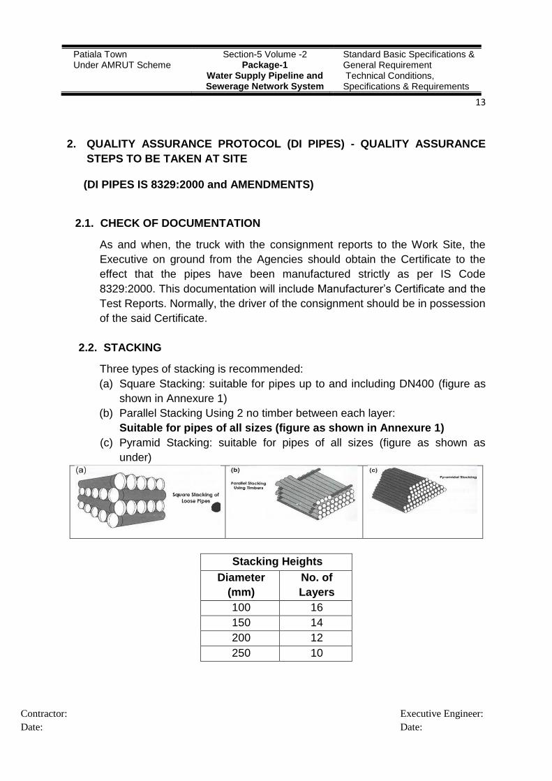
2.2. STACKING
Three types of stacking is recommended:
(a) Square Stacking: suitable for pipes up to and including DN400 (figure as
shown in Annexure 1)
(b) Parallel Stacking Using 2 no timber between each layer:
Suitable for pipes of all sizes (figure as shown in Annexure 1)
(c) Pyramid Stacking: suitable for pipes of all sizes (figure as shown as
under)
Stacking Heights
Diameter
(mm)
No. of
Layers
100 16
150 14
200 12
250 10
Patiala Town Under AMRUT Scheme
Section-5 Volume -2 Package-1
Water Supply Pipeline and Sewerage Network System
Standard Basic Specifications & General Requirement Technical Conditions, Specifications & Requirements
14
Contractor:
Date:
Executive Engineer:
Date:
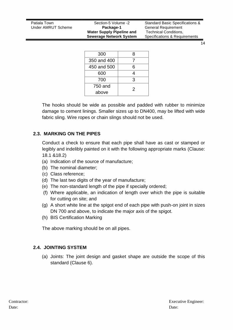
300 8
350 and 400 7
450 and 500 6
600 4
700 3
750 and
above 2
The hooks should be wide as possible and padded with rubber to minimize
damage to cement linings. Smaller sizes up to DN400, may be lifted with wide
fabric sling. Wire ropes or chain slings should not be used.
2.3. MARKING ON THE PIPES
Conduct a check to ensure that each pipe shall have as cast or stamped or
legibly and indelibly painted on it with the following appropriate marks (Clause:
18.1 &18.2)
(a) Indication of the source of manufacture;
(b) The nominal diameter;
(c) Class reference;
(d) The last two digits of the year of manufacture;
(e) The non-standard length of the pipe if specially ordered;
(f) Where applicable, an indication of length over which the pipe is suitable
for cutting on site; and
(g) A short white line at the spigot end of each pipe with push-on joint in sizes
DN 700 and above, to indicate the major axis of the spigot.
(h) BIS Certification Marking
The above marking should be on all pipes.
2.4. JOINTING SYSTEM
(a) Joints: The joint design and gasket shape are outside the scope of this
standard (Clause 6).

Patiala Town Under AMRUT Scheme
Section-5 Volume -2 Package-1
Water Supply Pipeline and Sewerage Network System
Standard Basic Specifications & General Requirement Technical Conditions, Specifications & Requirements
15
Contractor:
Date:
Executive Engineer:
Date:
(i) Push-on-Joint: In case of push-on flexible joints, the spigot ends shall
be suitably chamfered or rounded off to facilitate smooth entry of pipe
in the socket fitted with the rubber gasket (Clause 6.1, 6.1.1 & 6.1.2).
2.5. PHYSICAL CHARACTERISTICS
(a) A check of the following physical characteristics will be carried-out of
samples as mentioned above:-
(i) Sampling (Table in Clause 9.2)
(ii) Dimensions & Ovality (Clause 13, Table 2, Tolerances: Clause 15,
Table 7&8)
(Dimensions tests will be conducted at storage site)
2.6. MANUFACTURER TESTS
Sampling for Mechanical Acceptance Tests
(a) The mechanical acceptance tests shall be carried out on samples of
ductile iron pipes which shall be grouped in following batch sizes.(Clause
9.2)
DN (mm) Maximum Batch Size
80- 250 200 Pipes
300- 600 100 Pipes
700 - 1000 60 Pipes
1100 - 1400 40 Pipes
1600 - 2000 30 Pipes
In order to check compliance with the requirements specified in 10, a sample
ring or bar shall be taken from the spigot end of pipe. (Clause 9.3)
2.7. MECHANICAL TESTS (Clause 10)
Mechanical tests shall be carried out during manufacture. One test shall be
conducted for every batch of production. The number of pipes for each batch
shall be as laid down in 9.2. The results obtained shall be taken to represent
all the pipes of that batch. (Clause 10.1)
2.8. ZINC COATING (Clause 16.2 Annex A)
The mean dry film thickness of the finishing layer shall not be less than 70 µm
with nowhere less than 50 µm.
OR
BITUMINOUS COATING (Clause 16.2 Annex C)

Patiala Town Under AMRUT Scheme
Section-5 Volume -2 Package-1
Water Supply Pipeline and Sewerage Network System
Standard Basic Specifications & General Requirement Technical Conditions, Specifications & Requirements
16
Contractor:
Date:
Executive Engineer:
Date:
The mean thickness of the coating shall be not less than 70 µm and the local.
2.9. CEMENT MORTAR LINING (Clause 16.3 Annex B)
Thickness of the Lining (Clause B-5 Table 15)
2.10. HYDROSTATIC SITE TEST PRESSURES AND HYDRAULIC WORKING
PRESSURE
(Annex E Table 1 Amendment)
(a) Tests to be conducted for DI Pipe and Fittings at Two Laboratories
The following tests for DI Pipe and Fittings(as per IS 9523:2000) suitable
for push-on flexible joints are to be got conducted from the labs at
Research & Development Centre For Bicycle & Sewing Machines,
Ludhiana and Sri Ram at Delhi as per BIS:-
(i) Tensile Test (Clause 10.1.1 as per IS 8329:2000)
(ii) Brinell Hardness Test (Clause 10.2 as per IS 8329:2000)
(iii) Hydrostatic Test (Clause 11 as per IS 8329:2000)
(iv) Sizes (Clause 12 as per IS 8329:2000)
(v) Dimensions (Clause 13 as per IS 8329:2000)
(vi) Tolerances (Clause 15 as per IS 8329:2000)
(vii) Quality Assurance (Clause 17 as per IS 8329:2000)
(viii) Cement Mortar Lining (Clause 16.3 Annex B as per IS 8329:2000)
(ix) Bituminous Coating (Clause 16.2 Annex C as per IS 8329:2000)
(b) Rubber Gasket
The following test is to be got conducted from the labs at CIPET Amritsar
and Sri Ram at Delhi as per BIS:-
(i) The test is to be got conducted as per IS 5382 (1985): Rubber Sealing
Rings for Gas Mains, Water Mains and Sewers [PCD 13: Rubber and
Rubber Products] suitable for push-on flexible joints.
3. DI FITTINGS & SPECIALS
3.1. GENERAL
(a) The manufacturing unit should have ISO 9001 certification.

Patiala Town Under AMRUT Scheme
Section-5 Volume -2 Package-1
Water Supply Pipeline and Sewerage Network System
Standard Basic Specifications & General Requirement Technical Conditions, Specifications & Requirements
17
Contractor:
Date:
Executive Engineer:
Date:
(b) The company should have fully equipped laboratory with in-house
microscope to check modularity and to check chemical composition along
with tensile, hardness & elongation by universal testing machine. The
laboratory of the manufacturer should be accredited by NABL.
(c) Since the socket design is not given in the standard the min. socket
thickness of fittings at any point must not be lesser than minimum body
thickness given in the standard.
3.2. DESIGN REQUIREMENTS
(a) Classification
(b) The class of DI fittings to be provided shall be as specified in the data
sheet attached with this sub section. The external diameter and wall
thickness of fittings for Push on joints for the specified Class shall be as
per IS 9523 or equivalent.
(c) The Pressure class of flanged fittings shall be as specified in the data
sheet attached with this sub section and shall conform to the requirements
of IS 9523 or equivalent.
3.3. PERMISSIBLE DEVIATIONS ON LENGTH OF FITTINGS
The permissible deviations on the length of fittings shall be as per IS 9523 or
equivalent.
3.4. TOLERANCES
Tolerances on external diameter, Raised face height, thickness and Flange
drilling of fittings etc. shall conform to the provisions of IS 9523 or to the
provisions of international equivalent standard to which they are supplied.
3.5. MATERIAL REQUIREMENTS
The metal used for manufacturing the fittings shall conform to the appropriate
grade as specified in IS 1865, in commensurate with the requirements of IS
9523 or equivalent.
3.6. MANUFACTURING REQUIREMENTS
(a) The fittings shall be stripped with all precautions to avoid warping or
shrinkage defects, detrimental to their good quality. The fittings shall be
sound and free from surface or other defects.

Patiala Town Under AMRUT Scheme
Section-5 Volume -2 Package-1
Water Supply Pipeline and Sewerage Network System
Standard Basic Specifications & General Requirement Technical Conditions, Specifications & Requirements
18
Contractor:
Date:
Executive Engineer:
Date:
(b) Linings and Coatings for Ductile Iron Fittings
(c) The DI Fittings are to be lined with Cement Mortar Linings with a sand
cement mixture and the lining thickness should be as per Table 33 (
Annex B) of IS 9523. The Coatings to DI fittings shall be similar in line with
the provisions of DI pipes. All fittings must be painted with Zinc rich paint
as per Annexure A of IS 9523. Bitumen being used for External coating
should be approved By WRAS or similar approval authority. However, in
soil conditions where soil resistivity is less than 1000 ohm-cm with or
without water table, fusion bonded epoxy lined and coated DI fittings to be
used in place of other type of lined and coated fittings.
(d) Fittings with Flexible Push-on joint
(e) Flexible joints shall be of spigot and socket “push-on” type suitable for
angular deflection in any direction and capable of axial movement to
compensate for thermal expansion or contraction and ground movement.
(f) Fittings with Flanged joint
(g) Fittings with Flanged joints will be with raised face and they shall be
supplied complete with approved gaskets, hot dipped galvanized or
cadmium plated bolts, nuts.
(h) Fittings with Mechanical joint
(i) Where Fittings with mechanical type joints are specified, proposed and
approved they shall be supplied complete with approved gaskets, glands,
hot dipped galvanized or cadmium plated bolts, nuts and all other
necessary accessories.
(j) Fittings with Restrained Joints
(k) DI fittings with restrained joints shall be utilized in underground application
where pipelines have to cross roads through existing ducts or in areas
with restricted accessibility where the use of concrete anchor blocks is
prohibited, or as directed by the Engineer-in-Charge. The CONTRACTOR
shall submit with his bid with full details of the type of restrained joint he
proposes to use.
(l) Whenever in the course of work the CONTRACTOR intends to utilize
restrained joints he shall obtain prior approval from the Engineer-in-
Charge.
(m) Calculation of the number of pipe lengths with restrained joints required
on both sides of the fitting shall follow the manufacturer‟s recommendation
and shall be subject to the Engineer-in-Charge approval.

Patiala Town Under AMRUT Scheme
Section-5 Volume -2 Package-1
Water Supply Pipeline and Sewerage Network System
Standard Basic Specifications & General Requirement Technical Conditions, Specifications & Requirements
19
Contractor:
Date:
Executive Engineer:
Date:
(n) Restrained joints shall be designed in accordance with ISO 10804-1. The
permissible angular deflection will be as declared by the manufacturer.
The performance Type test of this Joint in line with ISO 10804-1/EN545
has to be established by the manufacturer by getting it witnessed by a
NABCB (National Accreditation Board for Certification Bodies) or IAF
(International Accreditation Forum) or EA (European Cooperation for
Accreditation) accredited institution / certification agency. The certificate
must be produced with the technical bid.
(o) Rubber ring for joints shall be of a type that will not deteriorate when
stored under manufacturer‟s guidelines or during operation. The rubber
gasket shall be of EPDM elastomer in accordance with IS5382 suitable for
water supply.
4. JOINTS BETWEEN PIPE AND FITTINGS
(a) Push on flexible joints shall be provided for pipe to fitting connection as per
IS 9523 or equivalent. Flange joints, wherever required, shall conform to the
requirements of IS 9523 or equivalent.
(b) Rubber gaskets
(c) Rubber gasket used shall conform to IS: 53821985 or amended up to date.
Other requirements of gaskets are as per clause-7 of IS 95232000. Rubber
Gaskets to be ISI marked EPDM quality.
5. TYPE TESTS
(a) The contractor / manufacturer shall carry out the type tests as listed in this
specification on the pipes to be supplied under this contract. The bidder shall
indicate the charges for each of these type tests separately in the relevant
schedule of Section VII (Forms & Procedures) and the same shall be
considered for the evaluation of the bids. The type tests charges shall be
paid only for the test(s) actually conducted successfully under this contract
and upon certification by the Employer.
(b) The type tests shall be carried out in presence of the Employer‟s
representative, for which minimum 15 days‟ notice shall be given by the
contractor. The contractor shall obtain the Employer‟s approval for the type
test procedure before conducting the type test. The type test procedure shall
clearly specify the test set–up, instruments to be used, procedure,

Patiala Town Under AMRUT Scheme
Section-5 Volume -2 Package-1
Water Supply Pipeline and Sewerage Network System
Standard Basic Specifications & General Requirement Technical Conditions, Specifications & Requirements
20
Contractor:
Date:
Executive Engineer:
Date:
acceptance norms, recording of different parameters, interval of recording,
precautions to be taken etc. for the type test(s) to be carried out.
(c) In case the contractor / manufacturer has already conducted such specified
type test(s), he may submit the type test reports to the Employer during
detailed engineering for consideration of waiver of conductance of such type
test(s) or otherwise as deemed fit by Employer. Such test(s) should have
been either conducted at an independent laboratory or duly approved by
accredited third party agency. The Employer reserves the right to waive
conducting of any or all the specified type test(s) under this contract. In case
type tests are waived, the type test charges shall not be payable to the
contractor.
(d) The type test shall be performed whenever a significant change is made in
the design, material or process of manufacture or a new size or size range of
the product is being supplied by the manufacturer.
5.1. JOINT LEAK TIGHTNESS TEST
(a) Tests for joints (push on flexible joints) shall be conducted as per the
guidelines of ISO 2531 to establish adequate joint performance with
respect to internal pressure, external pressure and vacuum pressure
under both normal alignment of joints and deflected alignment of joints as
dictated in ISO 2531.
(b) Tests for Leak tightness and mechanical resistance of flanged joints shall
be conducted as per ISO 2531.
(c) Cement Lining Smoothness Type Test
(d) The contractor / manufacturer should have carried out Cement Lining
Smoothness test to establish C value (Hazen & William‟s constant) of the
offered DI pipe as 140. Necessary certificate for the same shall be
furnished to the Employer.
(e) In case the contractor / manufacturer has not carried out the test, the
same shall be carried out by the contractor / manufacturer within the
scope of this contract.
(f) Ring bend test
(g) Ring bend test for 3% deflection with respect to external diameter of DI
pipe offered shall be conducted by contractor / manufacturer to prove that
internal cement mortar lining does not come off the substrate surface of
Ductile Iron on random basis for each manufacturing lot.

Patiala Town Under AMRUT Scheme
Section-5 Volume -2 Package-1
Water Supply Pipeline and Sewerage Network System
Standard Basic Specifications & General Requirement Technical Conditions, Specifications & Requirements
21
Contractor:
Date:
Executive Engineer:
Date:
(h) If the contractor / manufacturer of pipes do not have the facility for this
type test at his own works, the same can be arranged by him to conduct
and demonstrate the test.
5.2. MARKING
Each Pipe shall have as cast or stamped or legibly and indelibly painted on it
with the following marks:-
(a) The Manufacturer's name or trademark on each pipe
(b) The nominal diameter of pipes and batch number.
(c) Class of Pipes and fittings
(d) A white ring line showing length of insertion at spigot end
(e) Standard ISI certification mark for the pipes conforming to IS or
international standard mark to which they are supplied.
(f) The last two digits of the year of manufacture
(g) Any important information that the manufacturer deems fit to be inscribed
on pipe.
6. LAYING AND JOINTING OF DI PIPES
6.1. LAYING UNDERGROUND
(a) Pipes shall be lowered into the trench with tackle suitable for the weight of
pipes. For smaller sizes, up to 250 mm nominal bore, the pipe may be
lowered by the use of ropes but for heavier pipes suitable mechanical
equipment shall be used.
(b) All construction debris shall be cleared from the inside of the pipe either
before or just after a joint is made. All persons shall vacate any section of
trench into which the pipe is being lowered.
(c) The assembly for the pipes shall be made as recommended by the pipe
manufacturer and using the suitable tools.
(d) The socket and spigot ends of the pipes shall be brushed and cleaned.
The chamfered surface and the end of the spigot end have to be coated
with a suitable lubricant recommended by the manufacturer of the pipes.
Oil, petroleum bound oils, grease or other material, which may damage
the rubber gasket, shall not be used as lubricant. The rubber gasket shall
be inserted into the cleaned groove of the socket. It shall be checked for
correct positioning.
Patiala Town Under AMRUT Scheme
Section-5 Volume -2 Package-1
Water Supply Pipeline and Sewerage Network System
Standard Basic Specifications & General Requirement Technical Conditions, Specifications & Requirements
22
Contractor:
Date:
Executive Engineer:
Date:
(e) The two pipes shall be aligned properly in the pipe trench and the spigot
end shall be pushed axially into the socket either manually or with a
suitable tool specially designed for the assembly of pipes and as
recommended by the manufacturer. The spigot has to be inserted up to
the insertion mark on the pipe spigot. After insertion, the correct position
of the socket has to be tested with a feeler blade.
(f) Deflection of the pipes, if any, shall be made only after they have fully
been assembled. The deflection shall not exceed 75% of the values
indicated by manufacturer.
(g) On gradients of 1 in 115 or steeper, precautions shall be taken to ensure
that the spigot of the pipe being laid does not move into or out of the
socket of the laid pipe during the jointing operations. As soon as the joint
assembly has been completed, the pipe shall be held firmly in position
while the trench is back filled over the barrel of the pipe. The backfill shall
be well compacted.
(h) Special provisions in trench shall be made for accommodating socket
(Bell) of each pipe, as applicable so that barrel is uniformly rested on even
trench bed surface, which is well compacted as recommended in codes /
standards.
(i) At the end of each working day and whenever work is interrupted for any
period of time, the free ends of laid pipes shall be protected against the
entry of dirt, water or other foreign matter by means of approved plugs or
end caps.
6.2. LAYING ABOVE GROUND
(a) The following is applicable only when no additional bending moments
except that those due to self-weight of pipe and its content are present. If
any additional moments are present, piping contractor has to suitably
support the pipe in consultation with manufacturer and Employer.
(b) Socket and spigot pipes
(c) Socket (Bell) and spigot pipes shall be provided with one support (usually
pedestal or steel pipe support) per pipe. The supports shall be positioned
behind the socket of each pipe.
(d) Pipes shall be fixed to the supports with mild steel straps so that axial
movement due to expansion and contraction resulting from temperature
fluctuations is taken up at individual joints in the pipeline. Joints shall be

Patiala Town Under AMRUT Scheme
Section-5 Volume -2 Package-1
Water Supply Pipeline and Sewerage Network System
Standard Basic Specifications & General Requirement Technical Conditions, Specifications & Requirements
23
Contractor:
Date:
Executive Engineer:
Date:
assembled with the spigot end withdrawn 5 to 10 mm from the bottom of
the socket to accommodate thermal movements.
(e) The designed anchorage shall be provided to resist the thrusts developed
by internal pressure at bends, tees, etc.
(f) Where a pipeline crosses a watercourse, the design and method of
construction shall take into account the characteristics of the watercourse
to ascertain the nature of bed, scour levels, maximum velocities, high
flood levels, seasonal variation, etc., which affect the design and laying of
pipeline.
(g) Flanged pipes
(h) The maximum unsupported span for flanged pipes shall not be more than
8 m. The supports shall be located at the centre of every second pipe.
(i) The maximum unsupported span at water course shall also be not more
than 8 m. The relative position of pipe joints and pipe supports shall be as
per IS 12288 or equivalent.
(j) The supports of all flanged pipe work spans shall be stable and unyielding
due to movements in the pipeline.
(k) The straps shall prevent any lateral movement or lifting of the pipelines
but not restrict expansions and contractions caused by temperature
fluctuations.
6.3. CUTTING OF PIPES
(a) The cutting of pipe, if required, for inserting valves, fittings etc. shall be
done in a neat and workman like manner without damage to the pipe or
lining so as to leave a smooth end at right angles to the axis of the pipe.
Cutting of pipes shall be reduced to a minimum required.
(b) Cutting has to be made with suitable tools as per IS 12288 or equivalent
and according to the recommendations of the manufacturer. The spigot
end has to be chamfered again at the same angle as the original
chamfered end. If there is no mark for the insertion depth on the spigot
ends of the (cut) pipe it shall be marked again according to the
instructions of the manufacturer.
6.4. PIPELINE ANCHORAGE
(a) Pipeline shall be securely anchored at dead ends, tees, bends, tapers and
valves to resist thrust arising from internal pressure. Suitable thrust blocks
made of concrete shall be designed and cast- in-situ.

Patiala Town Under AMRUT Scheme
Section-5 Volume -2 Package-1
Water Supply Pipeline and Sewerage Network System
Standard Basic Specifications & General Requirement Technical Conditions, Specifications & Requirements
24
Contractor:
Date:
Executive Engineer:
Date:
(b) All specials like bends, tees etc. and appurtenances like valves etc. shall
be laid in synchronization with the pipes. The Contractor has to ensure
that the specials and accessories are available at site ready to be installed
together with the pipes.
6.5. EXTERNAL PROTECTION
(a) The details of soil resistivity data when enclosed with this specification is
for general guidance of the contractor and the accuracy, validity &
adequacy of the data shall be verified by the Contractor.
(b) The contractor shall carry out soil resistivity survey along the ROW of the
pipeline using Wenner‟s 4 pin method in the presence of Employer‟s
representatives.
(c) On completion of all field work, a report incorporating resistivity (on
semilog graph sheets) data shall be prepared by the contractor and
submitted to the Employer.
(d) In case of highly corrosive soil (soil resistivity less than 1000 ohm cm),
polyethylene sleeving shall be provided for encasement of the pipes,
fittings and joints against corrosion. This encasement shall be so
designed to prevent the contact of pipe, fittings and joints with the
surrounding backfill and bedding material. It shall conform to the
requirements of IS 8329 & IS 12288 or equivalent international standards.
6.6. HYDRAULIC TESTING OF PIPELINES
(a) After laying and jointing, the pipeline shall be tested for soundness and
leak tightness of pipes, fittings and joints, and soundness of any
construction work. The pipeline may be tested in sections.
(b) Water and other facilities as required for such hydro testing shall be
arranged by the Contractor. Each section shall be properly sealed off with
special stop ends secured by adequate temporary anchors. The thrust on
the stop ends shall be calculated and the anchors designed to resist it. All
permanent anchors shall be in position and, if of concrete, shall have
developed adequate strength before testing begins.
(c) Hydraulic Testing of Sections
(i) Pipes may be covered during testing. Joints shall be kept open for
visual inspection. The pipeline shall be filled with water and pressure
tested from the lowest point.

Patiala Town Under AMRUT Scheme
Section-5 Volume -2 Package-1
Water Supply Pipeline and Sewerage Network System
Standard Basic Specifications & General Requirement Technical Conditions, Specifications & Requirements
25
Contractor:
Date:
Executive Engineer:
Date:
(ii) The section under test shall be filled with water, taking care that all the
air is displaced either through vents at the high points or by using a
pig or a sphere. After filling with water the pipeline shall be left to
stabilize for a period of 1 hr. During the test period, make-up water is
continuously added to maintain the pressur. After filling, the pipeline
shall be adequately pressurized for a period of time to achieve stable
conditions.
(iii) The pipeline is then pressurized up to the full test pressure and the
section under test completely shall be closed off. The test pressure
shall be 1.5 times the rated pressure of pipes or of the proposed
maximum design pressure of the section. Apply the pressure by
continuously pumping at a constant rate.
(iv) The test pressure shall be maintained for a period of not less than 10
minutes to reveal any defects in the pipes, joints or anchorages. The
test pressure shall be measured such as to ensure that the required
test pressure is not exceeded at any point in the entire pipeline.
(v) If the test is not satisfactory, the fault shall be found and rectified.
Methods employed for finding faults shall be as per IS 12288.
(vi) Tests should be performed on reasonable lengths of pipelines. Long
lengths more than 2000 mtr .
(d) Hydraulic Testing of Complete Pipeline
(i) After all the sections have been joined together on completion of
section testing, a test on the complete pipeline shall be carried out.
This test shall be carried out at a pressure as specified in the data
sheet attached with this subsection. During the test, the pressure at
any point in the pipeline shall not exceed the pressure as specified in
the data sheet attached with this subsection.
7. G.I PIPES
G.I. Pipes G.I. pipes and specials should be medium class (B-Class) ISI marked
as per IS Code. Pipes should be wiped, clean & dry and free from clay, oil and
grease before they are laid. Inside of the socket and outside of spigot should be
wire brushed.
The pipe line should be properly cleaned/flushed before commissioning.

Patiala Town Under AMRUT Scheme
Section-5 Volume -2 Package-1
Water Supply Pipeline and Sewerage Network System
Standard Basic Specifications & General Requirement Technical Conditions, Specifications & Requirements
26
Contractor:
Date:
Executive Engineer:
Date:
8. SPECIFICATION FOR CI DOUBLE FLANGED SLUICE VALVES
(a) Sluice Valves for water supply shall be ISI marked in accordance with IS
14846 and as per list of Makes attached.. CI Flanged type of nominal sizes
80 to 600mm and pressure PN-1
(b) The components/parts of Sluice Valves shall be manufactured from
preferred material mentioned in table-1 of IS 14846 except for body seat
ring, Wedge facing ring and bushes which shall be made of stainless steel.
The Body Length over Flanges shall be as given under Column 3 i.e. PD in
table 3 of IS14846.
(c) Each valve shall be hydrostatically tested as per clause 10 of IS14846 for
closed end Test as well as open End Test. The Valves shall be suitable for
application in horizontal, position as well as for use in pipeline in
unsupported and terminal position rigidly held at one end only.
(d) The CI double flanged sluice valves shall be supplied either with Cap or with
Hand wheel.
(e) The bidder shall supply attested photocopies of license granted by BIS
authority to the manufactures for marking the CI, Double Flanged Sluice
Valves with ISI certification mark before inspection of materials.
9. SPECIFICATION FOR CI SURFACE BOXES FOR SLUICE VALVES
(a) ISI marked, CI surface Box for sluice valve conforming to IS 3950
(b) The contractor shall supply attested photocopies of license granted by BIS
authority to the manufacturer for moving C.I. surface box with ISI certification
mark before inspection of material.
10. CI/DI FITTINGS FOR CI/DI PRESSURE PIPES FOR WATER
The CI fittings shall conform to IS 1538. The metal used for manufacturing shall
be of a quality not less than that specified for grade-FG150 of IS 210. DI fittings
conforming to IS 9523 shall be used for DI pipes.
11. UNDERGROUND FIRE HYDRANT, SLUICE VALVE TYPE (WITH ROAD
SURFACE BOX)
(a) Under ground Fire Hydrant Sluice valves shall conform to IS909.
(b) The hydrants shall consist of the following components as detailed is IS909.
Patiala Town Under AMRUT Scheme
Section-5 Volume -2 Package-1
Water Supply Pipeline and Sewerage Network System
Standard Basic Specifications & General Requirement Technical Conditions, Specifications & Requirements
27
Contractor:
Date:
Executive Engineer:
Date:
(c) One double flanged 80mm i/d ISI marked sluice valve with one road surface
Box. The spindle of sluice valve shall be of stainless steel as per IS6603
(d) Duck foot bend.
(e) Flange riser.
(f) An externally threaded out let and outlet cap placed on the outlet by means
of chain.
12. SPECIFICATION FOR INDICATING PLATE FOR FIRE HYDRANT AND
SLUICE VALVES
(a) Enameled indicating plates made of 16 gauge Mild Steel sheet with ground
colour Prussian blue and letters in white enamel. The indicating plates
should have 4 No. holes of 4 mm dia meter for screws, on the corners. The
size of the plate shall be 150mm x 150mm with back side also black
enameled to protest if from rust. (As per drawing attached).
(b) The height and thickness of letters on the indicating plates shall be as per
drawing attached in this NIT.
(c) The margins of lettering, holes on four corners etc. shall be as per drawing
attached in this NIT.
13. SPECIFICATION FOR CI SPUN PRESSURE PIPES FOR WATER
(a) ISI marked, socket and spigot centrifugally cast (spun) iron pressure pipes
for water shall conform to IS1536 suitable for Rubber Gasket Jointing (push
on).
(b) The nominal lengths of pipes shall be 3.66 meter, 4.00 meter, 4.50 meter,
5.00 meter, 5.50 meter & 6.00 meter.
(c) At the time of supply, the bidder shall supply a certificate of manufacturer at
the time of inspection of material that each and every pipe has been tested
for “WORKS HYDRAULIC PRESSURE TIGHTNESS TEST” as per IS Code.
(d) ISI marked SBR quality Tyton Rubber Gaskets (Push on joint type) as per
IS5382 & IS12820 suitable for jointing of CI spun Tyton pipes.
(e) The bidder shall supply attested photocopies of license granted by BIS
authority to for marking the pipes & rubber rings with ISI certification mark
before inspection of material.

Patiala Town Under AMRUT Scheme
Section-5 Volume -2 Package-1
Water Supply Pipeline and Sewerage Network System
Standard Basic Specifications & General Requirement Technical Conditions, Specifications & Requirements
28
Contractor:
Date:
Executive Engineer:
Date:
14. HORIZONTAL CAST IRON PRESSURE PIPES
(a) ISI marked Double Flanged Horizontally cast iron pressure pipes as per
IS7181- Class B.
(b) The standard length of pipes shall be 2.75 meter.
(c) At the time of supply, the bidder shall issue a certificate that each and every
pipe has been tested for “WORKS HYDRAULIC PRESSURE TIGHTNESS
TEST” as per IS Code.
(d) The bidder shall submit attested photocopies of license granted by BIS
authority to the manufacturer for marking the pipes & rubber rings with ISI
certification mark. The license should clearly indicate the validity & class
covered in it.
15. VERTICALLY CAST IRON PRESSURE PIPES FOR WATER
(a) IS marked, Double Flanged Horizontally cast iron pressure pipes shall
conform to IS1537, Class B,
(b) The standard length of pipes shall be 2.75 meter (As per IS Code
366,4,4.88,5 & 5.5.m).
(c) At the time of supply, the bidder shall issue a certificate that each and every
pipe has been tested for “WORKS HYDRAULIC PRESSURE TIGHTNESS
TEST” as per IS Code.
(d) The bidder shall submit attested photocopies of license granted by BIS
authority to the manufacturer for marking the pipes & rubber rings with ISI
certification mark. The license should clearly indicate the validity & class
covered in it.
16. SPECIFICATION FOR SPUN HEMP YARN
Spun Hemp Yarn shall conform to IS6587. It shall be of variety No 3, (un-tarred)
as specified in table-1 of IS6587.
17. SPECIFICATION FOR PIG LEAD
(a) Pig lead shall be purity 99.99% conforming to IS27.
(b) The pig lead shall be arranged Minerals & Metals Trading Corporation of
India Limited.

Patiala Town Under AMRUT Scheme
Section-5 Volume -2 Package-1
Water Supply Pipeline and Sewerage Network System
Standard Basic Specifications & General Requirement Technical Conditions, Specifications & Requirements
29
Contractor:
Date:
Executive Engineer:
Date:
18. SPECIFICATIONS FOR PLASTIC FOOT STEP
(a) Foot step shall be of co-polypropylene coated over a 12mm diameter. Tor
steel bar and having dimensions as shown in the sketch attached with this
NIT.
(b) The step shall be tested at a load of 225 Kg as per IS 5455 (with up to date
amendments).
19. INSPECTION OF MATERIAL
(a) Inspection of material to be arranged by the contractor, for bonafide use on
this work, will be conducted at manufacturer premises except cement which
shall be inspected at site.
(b) The inspection of the material shall be carried out by an officer duly
authorized by the concerned Superintending Engineer.
19.1. FACILITIES FOR TESTS AND INSPECTION
The bidder shall at his own expenses afford to the Inspecting Officer, all
reasonable facilities and such accommodation as may be necessary for such
test and inspection. The Inspecting Officer shall have full and free access at
any time, during the execution of the contract to the manufacturer‟s works
from whom the supply of material is arranged for the aforesaid purpose and
the bidder is required to make arrangement for inspection of the material or
any part thereof at his premises or at any other place specified by the
Inspecting Officer.
19.2. COST OF TESTS AND INSPECTION
The bidder shall provide without any extra charge, all material, tools, labour
and assistance of every kind in which the Inspecting Officer may require for
any test and inspection. The Inspecting Officer shall in his sole judgment be
entitled to remove for test and inspection any of the material to any premises
other than his (manufacturer) premises.
19.3. LIABILITY FOR COSTS OF LABORATORY TEST
In the event of rejection of material or any part thereof by the Inspecting
Officer which is removed to the laboratory or other place of test, the

Patiala Town Under AMRUT Scheme
Section-5 Volume -2 Package-1
Water Supply Pipeline and Sewerage Network System
Standard Basic Specifications & General Requirement Technical Conditions, Specifications & Requirements
30
Contractor:
Date:
Executive Engineer:
Date:
contractor, on demand shall pay to the Engineer-in-charge all costs incurred in
such removal.
19.4. METHOD OF TESTING
The Inspecting Officer shall have the right to put all the material or part thereof
to such tests as he may think fit and proper. The bidder shall not be entitled to
object on any ground what so ever to the method of testing by the Inspecting
Officer.
19.5. REMOVAL OF REJECTED MATERIAL
If any material is rejected by the Engineer-in-charge after tests and inspection,
the material so rejected shall be removed from the premises of Engineer-in-
charge by the bidder at his own cost. Such rejected material shall under all
circumstance lie at the risk of the bidder from the moment of such rejection
and if such material is not removed by the bidder within a period of 3 days, the
Engineer-in-charge may dispose of such material in any way at the bidder‟s
risk and cost of the bidder. The Engineer-in-charge shall also be entitled to
recover handling and storage charges if incurred during which period the
rejected material is not removed.
19.6. ENGINEER-IN-CHARGE/AUTHORIZED REPRESENTATIVE RIGHT OF
REJECTION
Notwithstanding any approval which the Engineer-in-charge may have given
in respect of the material it shall be lawful for the Engineer-in-charge to reject
the material or any part thereof, if the material or any part or portion thereof is
not in conformity with the terms and conditions of the NIT.
E. SEWERAGE SYSTEM
1. EXISTING SEWERAGE SYSTEM
(a) Lateral Sewer : 439.00 Km
(b) Main Sewer : 65.00 Km
(c) House Connections : 48020 Nos
(d) STP(SBR Technology) : 2 No (46 MLD and 10 MLD)
Patiala Town Under AMRUT Scheme
Section-5 Volume -2 Package-1
Water Supply Pipeline and Sewerage Network System
Standard Basic Specifications & General Requirement Technical Conditions, Specifications & Requirements
31
Contractor:
Date:
Executive Engineer:
Date:
2. SCOPE OF WORK
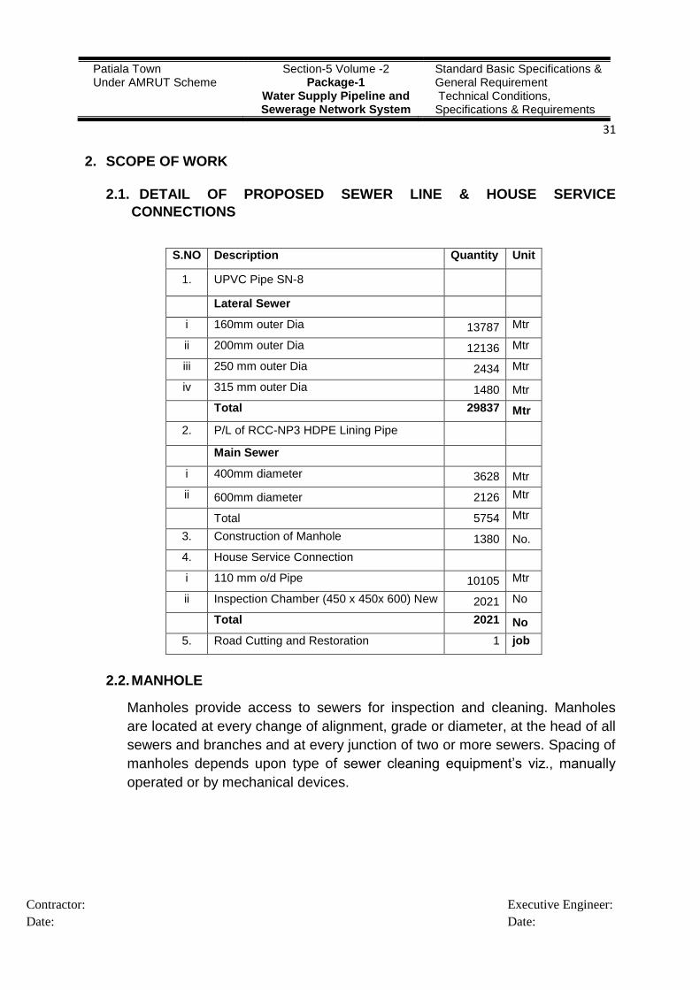
2.1. DETAIL OF PROPOSED SEWER LINE & HOUSE SERVICE
CONNECTIONS
S.NO Description Quantity Unit
1. UPVC Pipe SN-8
Lateral Sewer
i 160mm outer Dia 13787 Mtr
ii 200mm outer Dia 12136 Mtr
iii 250 mm outer Dia 2434 Mtr
iv 315 mm outer Dia 1480 Mtr
Total 29837 Mtr
2. P/L of RCC-NP3 HDPE Lining Pipe
Main Sewer
i 400mm diameter 3628 Mtr
ii 600mm diameter 2126 Mtr
Total 5754 Mtr
3. Construction of Manhole 1380 No.
4. House Service Connection
i 110 mm o/d Pipe 10105 Mtr
ii Inspection Chamber (450 x 450x 600) New 2021 No
Total 2021 No
5. Road Cutting and Restoration 1 job
2.2. MANHOLE
Manholes provide access to sewers for inspection and cleaning. Manholes
are located at every change of alignment, grade or diameter, at the head of all
sewers and branches and at every junction of two or more sewers. Spacing of
manholes depends upon type of sewer cleaning equipment‟s viz., manually
operated or by mechanical devices.
Patiala Town Under AMRUT Scheme
Section-5 Volume -2 Package-1
Water Supply Pipeline and Sewerage Network System
Standard Basic Specifications & General Requirement Technical Conditions, Specifications & Requirements
32
Contractor:
Date:
Executive Engineer:
Date:
2.3. BRICK RECTANGULAR MANHOLES CHAMBERS
Constructing brick masonry manhole in cement mortar 1:5 ( 1 cement : 5
coarse sand ) R.C.C. top slab 20cm thick using M-20 mix by using mixer and
vibrator, TMT Fe500 @ 63.464 kg/per cum, foundation concrete 1:4:8 mix (1
cement: 4 coarse sand : 8 graded stone aggregate 40mm nominal size) inside
plastering 12.5 mm thick with cement mortar 1:2 (1 cement: 2 coarse sand)
finished with floating coat of neat cement and making 40 mm thick benching in
cement concrete 1:2:4 (1 cement : 2 coarse sand : 4 graded stone aggregate
20mm nominal size) finished with a floating coat of neat cement, Orange
colour PVC steps including RCC cover with frame (extra heavy duty).
Complete as per standard design complete in all respects as per CSR Punjab
specifications.
2.4. VENTILATION SHAFTS
In modern, well designed sewerage system, there is no need to provide
ventilation on such elaborate scale considered necessary in the past,
especially with the present day policy to not intercepting traps in house
connections. The ventilating columns are not necessary where intercepting
traps are not provided. It is necessary however, to make provision for the
escape of air to take care of the exigencies of full flow and also to keep the
sewage as fresh as possible especially in outfall sewers.
The RCC ventilating shafts of 9.0m high have been proposed along the main
sewers with a distance of 1000m between two ventilating shafts as per
drawing.
2.5. MANHOLE COVERS AND FRAMES
The size of the manhole covers should be such that there should be clear
opening of not less than 560 mm diameter for manholes exceeding 0.90 m
depth. Provision of manhole covers has been in accordance to IS: 12592-
2002. The cover frame is proposed to be embedded in plain concrete on top
of masonry to correct alignment and level with suitable lifting arrangement.
2.6. HOUSE SERVICE CONNECTIONS
It has been decided that the provision of house service connections needs to
be provided under the project. A provision of House Service Connection

Patiala Town Under AMRUT Scheme
Section-5 Volume -2 Package-1
Water Supply Pipeline and Sewerage Network System
Standard Basic Specifications & General Requirement Technical Conditions, Specifications & Requirements
33
Contractor:
Date:
Executive Engineer:
Date:
Chambers (Inspection Chambers) has been provided, 1 No Inspection
Chamber outside the Property.
2.7. INSPECTION CHAMBER
Construction of brick masonry inspection chambers size as given below up to
0.60 mtr average depth in 1:5 cement sand mortar, lime concrete with 40 per
cent lime mortar 2:3 in foundation, cement concrete 1:2:4 benching 12.50mm
thick cement plaster 1:2 with a floating coat of 1mm thick of neat cement,
Providing and fixing of SFRC of RCC cover including 450mm frame medium
duty conforming to I.S.I complete as per standard design.
The property connections of sewage would be provided through Inspection
Chamber (I.C.), one I.C. Size of 450x450x600mm outside the property.
2.8. MAKING ROAD MOTOR-ABLE
After lying of pipeline, the refilling of trench will be done with the excavated
material with compaction shall be done as per specifications. The dismantled
road shall be made motor-able by using serviceable material collected
(including brick and interlocking tile) and well compacted with suitable roller.
No extra payment will be made for thus making road motor-able and no
deduction will be made for using service able material for making road motor-
able.
2.9. RESTORATION OF ROADS
The restoration of roads shall be done on deposit works through the agencies
that built/ modified the roads and the restoration of road shall be done as per
specification of dismantled Roads Road.
2.10. PIPELINE
(a) A permanent baseline, cross lines & bench marks shall be established to
serve as reference.
(b) All excavated materials obtained from excavation shall be Departments
property.
(c) The specifications given under this clause shall cover guide lines for
providing all types of pipes for sewerage, interconnecting pipes in
wastewater treatment units etc.
Patiala Town Under AMRUT Scheme
Section-5 Volume -2 Package-1
Water Supply Pipeline and Sewerage Network System
Standard Basic Specifications & General Requirement Technical Conditions, Specifications & Requirements
34
Contractor:
Date:
Executive Engineer:
Date:
(d) The diameters and types of pipes shall be as described in the approved
drawings. The pipes shall include all types of pipes. All the materials shall
be as per relevant Indian Standards. The specials and fittings shall be
installed in locations as per approved drawings or as directed by
Engineer-in-charge.
(e) The work includes supply of all types of pipes at the site of work, road
cutting and remaking, excavation of trenches in all types of soil, lowering
of pipes into the trenches, concrete bedding where specified, aligning to
line and grade, jointing, testing, back filling of trenches to meet the
requirements of Indian Standards codes of practices in a best
workmanlike manner.
(f) The Punjab PWD Specifications / IS Codes should be followed for work of
pipe laying.
3. SPECIFICATIONS OF MATERIALS
3.1. PIPELINE MATERIAL
The Material used in Pipeline work is Un-Plasticized Poly Vinyl Chloride
(U-PVC) and RCC-NP3 HDPE Lining. Construction of Manhole Brickwork
has size of 1200mm x 7500mm, 1500mmx 900mm, 1200mmx 1800mm
and 1500mmx 1800mm.
(a) U-PVC Pipe SN-8 as per IS:15328-2003 : 160mm outer dia to
315mm outer dia
(b) RCC Pipe Class NP-3 as per IS:458-2003: 400mm to 600mm dia
(c) Brick work in Manhole : As per CSR Punjab
(d) Manhole Cover(MD,HD & EHD) : As per IS12592-2002
(e) PVC Encapsulated Foot Steps : As per IS:10910
(f) Pipe Bedding: Providing and filling local sand as per specification for
uPVC & RCC NP3 pipes.
4. QUALITY ASSURANCE PROTOCOL FOR U-PVC PIPES
(U-PVC SN8 NON-PRESSURE PIPES AS PER IS 15328: 2003)
4.1. CHECK OF DOCUMENTATION
As and when, the truck with the consignment reports to the Work Site, the
Executive on ground from the Agencies should obtain the Certificate to the
Patiala Town Under AMRUT Scheme
Section-5 Volume -2 Package-1
Water Supply Pipeline and Sewerage Network System
Standard Basic Specifications & General Requirement Technical Conditions, Specifications & Requirements
35
Contractor:
Date:
Executive Engineer:
Date:
effect that the pipes have been manufactured strictly as per IS Code
15328:2003. This documentation will include Manufacturer‟s Certificate and
the Test Reports. Normally, the driver of the consignment should be in
possession of the said Certificate.
4.2. SAMPLING FOR PHYSICAL CHARACTERISTICS VISUAL APPEARANCE
AND DIMENSIONAL REQUIREMENTS
Samples Required for Dimensional requirements as per IS Code 15328:
(a) If no Failure. Minimum 13 Nos and maximum 50 Nos
(b) If Failure. Maximum 100 Nos
(As per Table 13 Clause F-1.1.1 and F-1.4.3)
4.3. MARKING ON THE PIPES
Conduct a check to ensure that each pipe is clearly and indelibly marked in
ink/paint or hot embossed on white base at intervals of not more than 3m as
under:-
(a) Manufacturer‟s name/Trade-mark
(b) Outside diameter
(c) Stiffness class (SN8)
(d) Batch or Lot Number and Period of Manufacture
(e) BIS Certification Marking
(f) Any other marking which would be prescribed by the ULB
The above marking should be on all pipes.
4.4. PHYSICAL CHARACTERISTICS
A check of the following physical characteristics will be carried-out of samples
as mentioned above as per IS Code 15328:
(a) Sampling (Table 13 Clause F-1.1.1 and F-1.4.3)
(b) Dimensions (Clause 6.1.1 to 6.1.4.1)
(Dimensions tests will be conducted at storage site)
(c) Appearance (Clause 7.1)
(i) The internal and external surface of the pipes should be smooth,
clean and free from grooving, blistering and any other surface
irregularity, which is likely to prevent conformance of the pipe with the
standard.

Patiala Town Under AMRUT Scheme
Section-5 Volume -2 Package-1
Water Supply Pipeline and Sewerage Network System
Standard Basic Specifications & General Requirement Technical Conditions, Specifications & Requirements
36
Contractor:
Date:
Executive Engineer:
Date:
(ii) Slight shallow longitudinal grooves or irregularities in the pipe are
permissible, provided the wall thickness remains within permissible
limits.
(iii) The pipe wall does not contain impurities or pores.
(iv) The pipe ends should be clearly cut and reasonably square to the
axis of pipe.
(d) Colour (Clause 7.2)
(i) The colour of the pipe should be dark (any shade of brown)
(ii) The pipe shall have uniform colour throughout the entire wall
(iii) Slight variations in the appearance of the colour are permitted.
(iv) Check for Cracks: Pipes shall be checked to ensure that during
transportation they have not cracked and care shall be taken during
unloading at site.
(v) Storage: Pipes shall be stored under shade and on pre prepared
leveled ground.
Notes:
i. A day before the pipes are to be received, CIPET Amritsar would be
contacted to dispatch a suitable person to assist the Departmental and
Consultant to conduct the above checks and take samples for the lab tests.
The lab tests for which samples are to be sent to CIPET Amritsar and Sri Ram
Lab at Delhi are mentioned at Para-6 below.
ii. The samples for the lab tests would be signed and sealed by all concerned.
This will ensure that no change can be made during transportation of
samples. The samples required for lab tests will be as per (Table 14 Clause F-
1.5.2 and F-1.6.2), (Table 15 Clause F-1.7.2), (Three samples of one meter
each are required for Resistance to Internal Hydrostatic Pressure Acceptance
test (1 hr/27C)
iii. 05 working days would be required to conduct the tests and the Report of the
tests should be obtained from CIPET on the sixth day (through E-mail).
iv. Once confirmation is received that all Reports/Test Results are in order then
the payment can be released as per the Contract Agreement.
4.5. TESTS TO BE CONDUCTED AT TWO LABORATORIES
The following tests are to be got conducted from the labs at CIEPT Amritsar
and Sri Ram at Delhi as per BIS:-

Patiala Town Under AMRUT Scheme
Section-5 Volume -2 Package-1
Water Supply Pipeline and Sewerage Network System
Standard Basic Specifications & General Requirement Technical Conditions, Specifications & Requirements
37
Contractor:
Date:
Executive Engineer:
Date:
(a) Vicat Softening Point (VSP)
(b) Longitudinal Reversion
(c) Resistance to External Blow at 0C
(d) Ring Stiffness
(e) Resistance to Internal Hydrostatic Pressure
(i) Acceptance Test (1 hr/27C)
(ii) Type Test (1000 hrs/60C)
(f) Internal Hydrostatic Pressure Test for Elastomeric Sealing Ring joints
Solvent Cement Joints. (applicable only for Pipe Joints)
(g) Internal negative Hydrostatic Pressure for Elastomeric Sealing ring
joints. Solvent cement joints. (applicable only for Pipe Joints)
(h) Sulphated Ash Content (Max 11%) (11% requirement is for Pressure
pipes. This being non-pressure UPVC pipe The %age of Sulphated ash
may be increased and fixed by Mutual understanding of buyer and seller,
optimize the cost)
(i) Density (1.40 to 1.46 gm/cc) (1.40-1.46 gm/cc range for density
requirement is for Pressure pipes. This being non-pressure UPVC pipe
The range for density may be increased and fixed by Mutual
understanding of buyer and seller, To optimize the cost)
Notes:
i. The tests listed at 1(j) & (k), though not mentioned in the IS Code are
considered essential to confirm there is no adulteration beyond the
maximum limit prescribed in the IS Code.
ii. These tests should be accordingly included in the Tender Documents.
5. QUALITY ASSURANCE STEPS TO BE TAKEN AT SITE
{PRECAST CONCRETE PIPES (WITH REINFORCEMENT)
NP3 AS PER IS 458:2003}
5.1. CHECK OF DOCUMENTATION
The Executive at site should obtain the following documents from the Agency
and Agency should obtain the same form the Supplier of pipes:-

Patiala Town Under AMRUT Scheme
Section-5 Volume -2 Package-1
Water Supply Pipeline and Sewerage Network System
Standard Basic Specifications & General Requirement Technical Conditions, Specifications & Requirements
38
Contractor:
Date:
Executive Engineer:
Date:
(a) Certificate to the effect that the Precast Concrete Pipes (with
Reinforcement) NP3 pipes have been manufactured strictly as per IS
code IS 458: 2003. This Certificate would include Manufacturer‟s Test
Certificate and Test Reports
(b) Conduct a check to ensure that each pipe is clearly and indelibly marked
in ink/paint or embossed on white base as under. The following markings
should be on all procured pipes/collars:-
(i) Identification of the source of Manufacture
(ii) Class and size of pipe/collar
(iii) The words „SPUN PIPE‟ or „VERTICAL CAST PIPE
(REINFORCED‟) as may be applicable, for pipes
(iv) Date of manufacture
(v) BIS Certification Marking
(vi) Any other marking which would be prescribed by the ULB.
(c) The above information shall be clearly marked on outside for pipes up to
and 350 mm internal diameter, and both outside and inside for pipes
above
350 mm internal diameter. The information shall be clearly marked on
the outside for collars.
(d) Obtain from the manufacturer a Certificate indicating the details relating
to quality, quantity and dispersion of steel in the pipes as well as the
clear cover to the steel provided in the pipes. (Clause 6.2.3 of IS
458:2003).
5.2. CLASSIFICATION
Class Description Conditions Where Normally Used
NP3 Reinforced (in case of pipes manufactured by vibrated casing process) concrete, medium-duty, non-pressure pipes
For drainage and irrigation use, for cross drains/culverts carrying medium traffic
NP4 Reinforced and also unreinforced (in case of pipes manufactured by vibrated casting process) concrete, heavy-duty, non-pressure pipes.
For drainage and irrigation use, for cross drains /culvert carrying heavy traffic
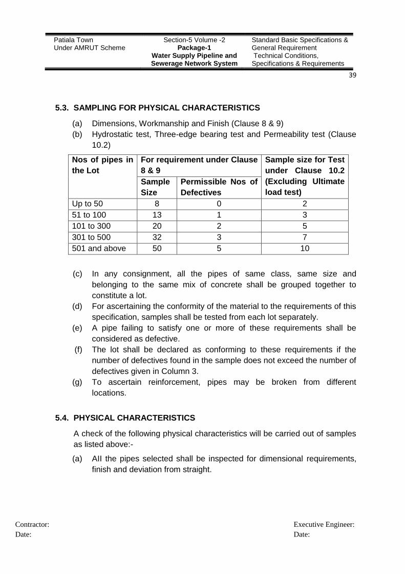
Patiala Town Under AMRUT Scheme
Section-5 Volume -2 Package-1
Water Supply Pipeline and Sewerage Network System
Standard Basic Specifications & General Requirement Technical Conditions, Specifications & Requirements
39
Contractor:
Date:
Executive Engineer:
Date:
5.3. SAMPLING FOR PHYSICAL CHARACTERISTICS
(a) Dimensions, Workmanship and Finish (Clause 8 & 9)
(b) Hydrostatic test, Three-edge bearing test and Permeability test (Clause
10.2)
Nos of pipes in
the Lot
For requirement under Clause
8 & 9
Sample size for Test
under Clause 10.2
(Excluding Ultimate
load test)
Sample
Size
Permissible Nos of
Defectives
Up to 50 8 0 2
51 to 100 13 1 3
101 to 300 20 2 5
301 to 500 32 3 7
501 and above 50 5 10
(c) In any consignment, all the pipes of same class, same size and
belonging to the same mix of concrete shall be grouped together to
constitute a lot.
(d) For ascertaining the conformity of the material to the requirements of this
specification, samples shall be tested from each lot separately.
(e) A pipe failing to satisfy one or more of these requirements shall be
considered as defective.
(f) The lot shall be declared as conforming to these requirements if the
number of defectives found in the sample does not exceed the number of
defectives given in Column 3.
(g) To ascertain reinforcement, pipes may be broken from different
locations.
5.4. PHYSICAL CHARACTERISTICS
A check of the following physical characteristics will be carried out of samples
as listed above:-
(a) AII the pipes selected shall be inspected for dimensional requirements,
finish and deviation from straight.

Patiala Town Under AMRUT Scheme
Section-5 Volume -2 Package-1
Water Supply Pipeline and Sewerage Network System
Standard Basic Specifications & General Requirement Technical Conditions, Specifications & Requirements
40
Contractor:
Date:
Executive Engineer:
Date:
(b) A pipe failing to satisfy one or more of these requirements shall be
considered as defective.
5.5. WORKMANSHIP AND FINISH (CLAUSE 9.0)
(a) Pipes shall be straight and free from crack except that craze cracks may
be acceptable.
(b) The ends of the pipes shall be square with their longitudinal axis so that
when placed in a straight line in the trench, no opening between ends in
contact shall exceed 3 mm in pipes up to 600 mm diameter (inclusive),
and 6 mm in pipes larger than 600 mm diameter.
(c) The outside and inside surfaces of the pipes shall be dense and hard
and shall not be coated with cement wash or other preparation.
(d) The inside surface of the pipe shall be smooth.
(e) For better bond, inner surface of the collar may have rough finish.
(f) The pipes shall be free from defects resulting from imperfect grading of
the aggregate, mixing or moulding.
(g) Pipes shall be free from local dents or bulges greater than 3.0 mm in
depth and extending over a length in any direction greater than twice the
barrel wall thickness.
(h) Pipes may be repaired, if necessary, because of accidental injury during
manufacture or handling and shall be accepted if in the opinion of the
Engineer-in-Charge, the repairs are sound and appropriately finished
and cured, and the repaired pipe conforms to the requirements of this
specification.
5.6. DEVIATION FROM STRAIGHT
The deviation from straight in any pipe throughout its effective length, tested
by means of a rigid straight edge as described in IS 3597 shall not exceed, for
all diameters, 3 mm for every metre run.
5.7. TESTS TO BE CONDUCTED AT TWO LABORATORIES
The following tests are to be got conducted from an authorised and reputed
NAB approved labs:-
(a) The specimens of pipes selected in accordance with 10.1 shall be
subjected to the following tests in accordance with IS 3597:-
(i) Permeability Test

Patiala Town Under AMRUT Scheme
Section-5 Volume -2 Package-1
Water Supply Pipeline and Sewerage Network System
Standard Basic Specifications & General Requirement Technical Conditions, Specifications & Requirements
41
Contractor:
Date:
Executive Engineer:
Date:
(ii) Hydrostatic Test
(iii) Three-Edge Bearing Test
(iv) Split Tensile Tests of concrete cylinder (see 5.5.2) made from the
concrete used for the pipes.
(b) Rubber Ring chords used in pipe joints shall conform to Type-2 of IS
5382.
Note:
i. The permeability test when conducted in accordance with the method
described in ISL3597 shall meet the requirement of final permeability,
which shall not exceed 0.3 cm3.
ii. Initial absorption should not exceed 2.0 cm3 and the deviation in any two
readings during initial absorption should not be more than 8 cm3.
iii. For Non-pressure pipes, 2% of the pipes shall be tested for hydrostatic
test pressure.
6. QUALITY ASSURANCE PROTOCOL HDPE T-GRIP FOR LINING FOR RCC
PIPES
6.1. GENERAL
(a) T-grip liner is new introduction for lining of concrete pipes with a
Polyethylene material. The following guidelines have been made to
ensure that the product is of a material of laid down quality parameters.
(b) T-grip PE Liner should be made from Polyethylene compound. To
maintain the characteristics, Manufacturers can use combination PE
materials. However, the liner and allied products used for installation
should be made from the propriety grade resin. The T-grip PE liners, the
actual resin used in manufacture must constitute not less than 99% of
the resin used in formulation. The Manufacturer is permitted to make
changes in the formation of the T-grip PE liner, but only after prior
approval from the Engineer-in-Charge of Project and technical
demonstration no quality parameters are compromised.
(c) At any time during the course of Project, whether during Manufacture of
the specified T-grip PE liner or in its installation finally in the RCC Pipe,
the Engineer-in-Charge should retain samples of the T-grip PE liner or
welding strips for testing.

Patiala Town Under AMRUT Scheme
Section-5 Volume -2 Package-1
Water Supply Pipeline and Sewerage Network System
Standard Basic Specifications & General Requirement Technical Conditions, Specifications & Requirements
42
Contractor:
Date:
Executive Engineer:
Date:
(d) Properties
The following are the main properties T-grip PE liner:
Ser
No
Test UOM Value Test Method
1. Material HDPE
2. Density g/cc 0.93-0.94 ASTM D 1238
3. Melt Flow Rate (190 deg. C, 2.16
kg. wt.)
g/10 min. ≤ 1.00 ASTM D 638
4. Tensile Strength at Yield MPa ≥15 ASTM D 638
Tensile Strength at break MPa ≥24 ASTM D 638
5. Elongation at Yield % 12(Min) ASTM D 638
Elongation at break % 600(Min) ASTM D 1603
6. Carbon Black content % 2-3 ASTM D 2240
7. Shore durometer 1-sec. ≥50
10-sec.240
ASTM D 570
8. Water Absorption % ≤0.08 ASTM D 4801
9. Thickness Mm 1.65 (Min)
HDPE T-grip manufacturer should have in house testing facility for the
tests which are mentioned in this circular.
(e) All T-grip PE liner including locking extensions, all joints and
welding strip shall be free of cracks and other defects that may
affect the protective properties of the material.
(f) Colour
Colour of T-Rib PE liner shall be of twin colour. In twin colour,
Portion of T-rib (Outer layer) which is embeded in RCC Pipe shall be
Black-UV resistant and portion (Inner layer) which are come in
contact with fluid shall be Grey/Blue.
(g) Thickness of inner layer should be 20% of the thickness of total T-
rib e.g. If T-rib liner thickness is 2.5mm, then inner layer thickness
should be 0.5mm.
(h) Test
(i) General:
a. Sample taken fro T-grip PE liner, Joints or Weld Strips shall be
tested to determine material properties.

Patiala Town Under AMRUT Scheme
Section-5 Volume -2 Package-1
Water Supply Pipeline and Sewerage Network System
Standard Basic Specifications & General Requirement Technical Conditions, Specifications & Requirements
43
Contractor:
Date:
Executive Engineer:
Date:
b. Determination of tensile strength and elongation shall be
accordance with ASTM D 638 using Die IV. Determination of
indentation hardness shall be in accordance with ASTM D2240
using type D Durometer, except that a single thickness of material
and indentation hardness shall be made on 1x3 inch (25x75mm)
specimens. Thickness of specimen shall be the thickness of the
sheet or strip.
(ii) Measurement of initial Physical Properties:
This measurement determines the initial values for tensile strength,
weight, elongation and indentation hardness prior to chemical
resistance test.
(iii) Chemical Resistance Test:
a. Determine the physical properties of the specimens after
exposure to chemical solutions.
b. Test specimen shall be conditioned to constant weight as 72◦F
(24◦C) before and after submersion in the followig solutions for a
period of 112 days at 72◦+or-5◦F (24◦+or-3◦C).
Chemical Test
Method
Change in Weight
Not more than
Sodium Hypo-Chloride 1%
As per
ASTM D
543
0.09%
Ferric Chloride 1% 0.09%
Sodium Chloride 5% 0.09%
Sulphuric Acid 20% 0.09%
Nitric Acid 1% 0.09%
Sodium Hydroxide 5% 0.09%
Ammonium Hydroxide 5% 0.09%
Soap & Detergent Solution
2% 0.09%
c. At 28 day intervals, specimen shall be removed from each
chemical solution and tested. If any specimen fails to meet the
112 day exposure, the material will be subject to rejection.
d. Chemical Resistance test to be performed as type test once in
year.
(iv) Details and Dimensions:
a. Approval of Detail: T-grip PE liner, strip and other accessory
pieces shall conform to the requirements of these specifications
and applicable provision of standard plans.

Patiala Town Under AMRUT Scheme
Section-5 Volume -2 Package-1
Water Supply Pipeline and Sewerage Network System
Standard Basic Specifications & General Requirement Technical Conditions, Specifications & Requirements
44
Contractor:
Date:
Executive Engineer:
Date:
b. Thickness of Material: The minimum thickness of sheet and strip
shall be as follows:-
Material Thickness
Sheet with
Locking
Extensions
1.65 mm min (for size up to 300mm RCC Pipe)
2.00 mm min (above 300 mm and less than 600 mm)
2.50 mm min (above 600m and less than 1200mm)
Sheet Plain 1.65 mm min
Joint Strip 1.65 mm min
Weld Strip 1.65 mm min
c. Unit weight w.r.t thickness of material: The Approximate unit
weight with respect to thickness shall be as follows:- Thickness Unit weight-kg/m
2
2.00 mm 3±2%
2.50 mm 3.4±2%
3.00 mm 3.95±2%
d. Material Sizes: T-grip PE liner used for RCC pipe shall be sized
to provide the coverage by the plans.
e. Locking Extensions:
i. T-grip PE liner to be embedded in concrete shall have internal
locking extensions.
T-grip PE liner be anchored to concrete surfaces during vertical
casting of RCC pipes.
ii. Locking extensions shall be of the same material as the T-grip
PE liner, shall be integrally extruded with the PE liner, it should
have an approved cross section with a minimum web thickness
of 3 mm. They shall be ≥ 63.5 mm apart and shall be such that
when the extensions are embedded in the concrete, the liner will
be held permanently in place. Height of Locking extensions
should be ≥ 11 mm from bottom of PE liner. Width of locking
extension should be ≥10.00 mm.

Patiala Town Under AMRUT Scheme
Section-5 Volume -2 Package-1
Water Supply Pipeline and Sewerage Network System
Standard Basic Specifications & General Requirement Technical Conditions, Specifications & Requirements
45
Contractor:
Date:
Executive Engineer:
Date:
iii. Locking extensions shall be parallel and continuous except
where interrupted for joints flaps, weep channels, strap channels
and for other purposes shown on the plans or permitted by the
engineer.
iv. The T-grip PE liner edge which will be lower terminal edge in the
structure shall not extend beyond the base of the final locking
extensions more than 3/8 inch (10mm).
f. Flaps: When transverse flaps are specified or required, they shall
be fabricated by removing locking extensions so that maximum of
0.32 inch (0.8mm) of the base of the locking extensions remains on
the sheet.
g. Pull Test for Locking Extensions: T-grip PE liner locking
extensions embedded in concrete shall withstand a test pull of at
least 75 pounds per linear inch applied perpendicularly to the
concrete surface for a period of 1 minute, without rupture of the
locking extensions or withdrawal from embedment. This rest shall
be made at a temperature between 86◦F to 95◦F (30◦C to 35◦C)
inclusive.
h. Water Absorption Rate
i. (% change maximum in original weight) as per ASTM D570.
ii. Results are 0.1% over first 24 hours then the rate drops rapidly.
Total absorbed amount is not increased over prolonged period.
i. Water Vapor Transmission Rate:
i. This test is to be performed as per ASTM E96 (38◦C and 100%
relative humidity).
ii. The transmission rate should be 0.020 (per 100 square inches
per day) for T-grip PE liner thickness of 1.5mm.
j. Co-Efficient of Linear/Thermal Expansion:
i. This test is to be performed as per ASTM D696.Test results
should be 1.2x10⁻⁴ per ◦C rise in temperature.
ii. T-grip PE liner should not exhibit significant
contraction/expansion differentials to concrete. Hardness-Shore
Durometer “D” should be 55 to 25◦C as per ASTM D2240 test
method.
k. Oxidation Induction Time (OIT): This test to be performed as per
ISO-11357/ Test results should be ≥ 20 minutes minimum at 200◦C.
l. Shop Welded Joints: Shop welded joints, used to fuse individual
sections of T-grip PE liner together, shall be at least equal to the
minimum requirements of the liner for thickness, and shall be

Patiala Town Under AMRUT Scheme
Section-5 Volume -2 Package-1
Water Supply Pipeline and Sewerage Network System
Standard Basic Specifications & General Requirement Technical Conditions, Specifications & Requirements
46
Contractor:
Date:
Executive Engineer:
Date:
tested for tensile strength. Tensile strength measured across the
welded joints as well as Hot-air fabrication welds, shear value shall
be 90% of Yield strength of the parent material using a 1x5 straight
die.
m. Spark Test: All liner shall be shop tested for holes with a spark
tester set to 20,000 volts to 30,000 volts. Sheets having holes shall
be satisfactorily repaired in the shop prior to shipment from the
manufacturer‟s plant.
There should be marking of batch number and manufacturer
brand at regular interval on every 50 meters.
7. DESIGN CRITERIA
Design Period. The design period for the project is taken as 30 years. With initial
year as 2015, intermediate design year will be 2030 and Ultimate design year will
be 2045
The proposed sewerage network is designed for the ultimate stage flows
expected in the year 2045, considering a design period of 30 years (excluding
construction period).
Per Capita Sewage Flow: As per CPHEEO norms, about 80% of water supply
finds its way as wastewater into sewers i.e. 108 lpcd. In addition to that 5%
provisions have been made for non-domestic flows.
Per capita flow of 113.40 lpcd, including provisions for infiltration 5% of the
average flow sewage generation has been considered for the design.
7.1. GROUND WATER INFILTRATION FACTOR
When the Ground water table is high, there will be some infiltration into the
sewers. The pipe joints are the locations where the infiltrations are expected
much. They influence in increasing the depth of flow in the sewer pipeline.
The allowance for infiltration of groundwater at the rate of 500 to 5000
liter/km/day for sewers or 250 to 500 liters/manhole or 5000 to 50000
liters/ha/day is proposed in the CPHEEO Manual. Generally, infiltration per
length of sewer is adopted in design. CPHEEO manual indicates that this
shall tend to minimum.
7.2. PEAK FACTOR
Peak factor or the ratio of maximum to average flows. Computation of peak
flow in design of the underground sewerage network is considered based on

Patiala Town Under AMRUT Scheme
Section-5 Volume -2 Package-1
Water Supply Pipeline and Sewerage Network System
Standard Basic Specifications & General Requirement Technical Conditions, Specifications & Requirements
47
Contractor:
Date:
Executive Engineer:
Date:
cumulative nodal population.
Hydraulics of Sewers: Flow in sewers is said to be steady, if the rate of
discharge at a point in a conduit remains constant with time, and if the
discharge varies with time, it is unsteady. The hydraulic analysis of sewers is
simplified by assuming steady flow conditions. The design of wastewater
collection system presumes flow to be steady and uniform. A properly
functioning sewer has to carry the peak flow for which it is designed and
transport suspended solids in such a manner that deposits in a sewer are kept
to minimum. The unsteady and non-uniform wastewater flow characteristics
are accounted in the design by proper sizing of manholes.
7.3. DESIGN FLOW-FRICTION FORMULA
The available head in sewers is utilized in overcoming surface resistance and,
in small part, in attaining kinetic energy for flow. The design practice is to use
the Manning‟s formula for open channel and the Hazen Williams or Darcy –
Weisbach formula for closed conduit or pressure flow.
Manning‟s formula will be adopted for the design of sewers.
V=1/n * R2/3*S1/2
Q = A ×V
Where:
Q = Discharge in (m3/sec)
A = Cross-sectional area in (m2)
S = Slope of hydraulic gradient
D = Internal dia of pipeline in (m)
V = Velocity in (m/sec)
R = Hydraulic radius in (m)
n = Manning‟s coefficient of roughness
7.4. MANNING’S COEFFICIENT OF ROUGHNESS
Manning‟s roughness coefficient varies with the type of pipe material used in
sewer construction. As pipes deteriorate with age, a roughness coefficient is
considered for the design period assuming fair condition in sewers. The
roughness coefficient N is considered same for all diameters when flowing full
and is adopted for new U-PVC pipe and RCC HDPE Lining pipe as 0.011.

Patiala Town Under AMRUT Scheme
Section-5 Volume -2 Package-1
Water Supply Pipeline and Sewerage Network System
Standard Basic Specifications & General Requirement Technical Conditions, Specifications & Requirements
48
Contractor:
Date:
Executive Engineer:
Date:
7.5. MINIMUM DIAMETER OF PIPE
As per CPHEEO manual minimum sizes of sewer of 160 mm o/d U-PVC pipe
is considered and for other reaches above 315 mm o/d, HDPE lined RCC
pipes are proposed.
F. STANDARD BASIC SPECIFICATION
1. GENERAL
(a) During construction of work all the conditions as per Punjab, C.S.R. will
be applicable
(b) Sanction from Railways, Forest Dept., B&R and PSEB etc. will be
arranged by the Employer. Payment if made to the concerned
Department by the agency will be reimbursed to the agency on actual
receipt of the Department.
(c) All the safety precautions will be taken to avoid any damage/incident.
(d) Electric poles, telephone cables, trees etc. should be protected with due
care. The contractor will be responsible for any damage to Electric Pole
& Wires Telephone cables etc. any payment on this account, will be
borne by him.
(e) Suitable arrangement must be made for street drainage.
(f) There should be approach for houses.
(g) Specification may have to be changed as per site conditions for which
nothing extra will be paid.
(h) All the sewer lines will be got tested by contractor before filling. If there
is any leakage or damage during execution or after commissioning, the
same will be rectified by the contractor at his own cost, loss or damage
what so ever may be shall be borne by the contractor.
(i) Material defect, execution defect or other defect such as gradient etc if
any on the part of the contractor, found at later stage which could not be
traced while execution due to hidden work and are not part of
maintenance, will remain the responsibility of the contractor to set right
the same at his own cost though he may have taken his all dues.
(j) Cross-Sections of Excavation: The cross-section of excavations
adopted in Estimate is not standard. Hence depending upon the nature
of soil, depth of excavation and spring level, the required slope should
be approved by the concerned SE and paid accordingly.
Patiala Town Under AMRUT Scheme
Section-5 Volume -2 Package-1
Water Supply Pipeline and Sewerage Network System
Standard Basic Specifications & General Requirement Technical Conditions, Specifications & Requirements
49
Contractor:
Date:
Executive Engineer:
Date:
(k) Offset in Excavation: Since, the excavation is not too deep and suitable
side slope have been is proposed. Hence there is no need of providing
offset in the excavation (as in such cases, sub-soil water level very near
to the ground level), pumping sets can be provided at ground level.
Payment should be restricted accordingly.
(l) Carriage of Surplus Earth/Spoils: Carriage of surplus earth should be
paid as per CSR Item No 29.7 C
(m) Tender Rated: To avoid in-balanced tenders, it should be ensured that
rates quoted by contractor should be % below or above the scheduled
item taken in DNIT of the work.
(n) uPVC/RCC Pipes should be ISI Marked.
All the RCC / uPVC Pipes to be utilized in the work should be procured
from and approved manufactured (who has the manufacturing unit as
per the laid down IS standard i.e. has the requisite BIS Certificate).
Before procuring these pipe should be got tested as per the relevant IS
Code.
(o) Level & Gradients. While execution of the work it should be ensure that
sewers have been laid as per Design Statement (approved) i.e. at
proper levels and gradients.
(p) Execution of work. The work of laying pipeline should commence from
the downstream and no gap should be maintained while laying the pipe
lines.
(q) Commissioning of Pipes. Before commissioning the pipe line they
should be tested to confirm there is no leakage and requisite water
flows in the concerned pipe line.
(r) The detailed technical specifications for all the items are covered in this
part of the tender documents. In case any item is not covered or
missing, Punjab, PWD book of specifications, relevant IS code Manual
on water supply & water treatment & Manual on sewerage and sewage
treatment shall have to be followed upon. Approval of Engineer-in-
Charge is required in this case.
(s) Moreover, in case of any discrepancy between specifications laid down
in this document and Punjab PWD book of specifications/relevant IS
code, the decision of the Engineer-in-Charge will be final & applicable.
(t) Wherever reference is made to Indian Standard Specifications, the
latest amendments shall be applicable.
(u) Miscellaneous
Patiala Town Under AMRUT Scheme
Section-5 Volume -2 Package-1
Water Supply Pipeline and Sewerage Network System
Standard Basic Specifications & General Requirement Technical Conditions, Specifications & Requirements
50
Contractor:
Date:
Executive Engineer:
Date:
(i) Road cutting
Road cutting of any type viz. Brick flooring, CC flooring, metal led
road will be done wherever required before laying the water
supply/sewerage lines.
(ii) Shifting of Electric and Telephone poles
Electric and telephones poles coming in the alignment of sewerage
lines and causing any hindrance in the execution of the work will be
got shifted by the agency from the concerned department at his
level. Payment if any made to the concerned department will be
reimbursed to the agency on actual receipt of the department.
(v) Drawings
(i) Tentative Layout Plan are being made available by the PWSSB to
the Bidder.
(ii) 2.Drawing of manholes for pipe sewer
(iii) 3.Drawing of X- Section of uPVC/R.C.C. pipe sewer
(w) As-built Drawings
After construction and commissioning of all civil works mentioned
above, the contractor shall submit the five complete sets of As-built
Drawings along with editable soft copy. The As-built Drawings are the
Detailed Engineering Drawings showing the actual details on which the
Construction/Fabrication/Erection has been carried out. The contractor
shall have to obtain approval of the As-built Drawings from the
Engineer.
(x) Activity Bar Chart
The successful bidder shall submit Activity Bar Chart, giving Time
Schedule for each activity according to priorities of Engineer-in-charge.
The construction activities shall be based on this Bar Chart. Whenever
there is a deviation from the approved Bar chart, a revised Bar chart
shall be submitted by the Contractor. During the construction duration
the updated Bar Chart shall be submitted to the Engineer-in-Charge
from time to time.
2. EARTH WORK
General

Patiala Town Under AMRUT Scheme
Section-5 Volume -2 Package-1
Water Supply Pipeline and Sewerage Network System
Standard Basic Specifications & General Requirement Technical Conditions, Specifications & Requirements
51
Contractor:
Date:
Executive Engineer:
Date:
The conditions/specifications laid down hereunder will hold good whether the
excavation is to be carried out over areas for leveling, foundations of structures,
trenches for pipes or cables or any other type of work which involves earth work
like leveling or forming/embankments etc as per Punjab, PWD specifications.
(a) Earthwork in excavation includes site-clearing activities like removal of
shrubs, loose stones, and rubbish of all kinds, interfering with the works and
with complete removal of roots.
(b) The products of the above clearing operations shall be removed from the
site, dumped, stacked at a place or places, burnt or otherwise disposed of
as directed by the Engineer-in-Charge with in the compound.
(c) A permanent base line and cross lines shall be established to serve as
reference grid using MS plates, pegs, pins set in concrete or brick masonry
pillars where they will be free from disturbances.
(d) A permanent bench mark or marks as required necessary for the works
connected to the nearest GTS benchmark shall be established for reference.
(e) Excavation shall be carried out in all types of soil like top soil, silt, sand,
gravel, soft murram, clay, kanker, hard materials like disintegrated rock
shale which can be removed by picks, crow bars and showels. Soil/earths
may contain boulders. Loosening of rocks include the other methods of
excavation other than blasting such as chiseling, wedging line drilling to
avoid shattering of rock. The Engineer-in-Charge shall decide what method
shall be adopted for removal of the hard rock.
(f) All excavation shall be strictly done true to line, level, grade or slope as the
case may be for the respective structure as shown in the drawings/directed
by the Engineer-in-Charge.
(g) Sides and bottoms of excavation shall be cut sharp and true. Under cutting
shall not be permitted. Earth sides of excavation shall not be used in lieu of
formwork for placement of concrete unless authorised in special cases, by
the Engineer-in-Charge where limitation of space for larger excavation
necessitates such decision.
(h) Excavation, whose sides are required to be maintained at a steeper slope
than the stable slopes, will be required to be properly stored and strutted
failing which the contractor will be required to execute the work by open
cutting by the approval of Engineer-in-Charge.
(i) Negligence on account of this leading to any mishap will be entirely the
responsibility of the contractor.
Patiala Town Under AMRUT Scheme
Section-5 Volume -2 Package-1
Water Supply Pipeline and Sewerage Network System
Standard Basic Specifications & General Requirement Technical Conditions, Specifications & Requirements
52
Contractor:
Date:
Executive Engineer:
Date:
(j) All surplus soil/earth shall be transported and disposed off as directed by the
Engineer-in-charge. The rates quoted by the contractor shall be deemed to
be inclusive of all such works.
3. DRAINAGE IN THE VICINITY OF EXCAVATION
(a) The contractor shall control the drainage in the vicinity of all Excavation so
that the surface of the ground will be properly sloped to prevent surface
water running into excavated areas during construction. Arrangements shall
be made for preventing rain and other extraneous liquids entering the
excavated parts. Seepage water shall be directed to flow away from the
trenches by gravity. If any pumping is required to keep the trench and the
exposed areas dry for further work the same shall be done by the contractor
at his own expenses.
(b) The rates quoted by the contractor shall be deemed to be inclusive of all the
above costs or charges for stipulations stated above.
(c) Excavated material shall not be deposited within 1.5 meters from the top
edge of the excavation in case of MPS and 0.6m in case of sewerage.
(d) The contractor shall remove the excavated material to spoil heaps on the
site transport the same to a place as directed by the Engineer-in-Charge.
(e) If the bottom of the excavation is left exposed by the contractor and in the
opinion of the Engineer-in-Charge it has become deleteriously affected by
atmospheric changes or affected by water then the contractor shall remove
at his own cost such portions of the affected foundations and shall make
good by filling with lean concrete or with compacted sand as directed by the
Engineer-in-Charge.
(f) Where Excavation is made in excess of the depths required as shown in the
drawings or as directed by the Engineer-in-Charge the contractor shall at
his own expense fill up to the required level with lean concrete or well
compacted sand as decided by the Engineer-in-Charge.
(g) Loose, soft or bad soil encountered in Excavation at the required depth on
Engineer-in-Charge's directions shall be excavated to the firm bed and the
difference of levels between the required level and the firm bed shall be
filled up or dealt with as directed by the Engineer-in-Charge.
(h) Any obstacle encountered during excavation shall be reported immediately
to the Engineer-in-Charge and shall be dealt with as instructed by him.
Same shall be applicable for any antiques/treasure found during Excavation.

Patiala Town Under AMRUT Scheme
Section-5 Volume -2 Package-1
Water Supply Pipeline and Sewerage Network System
Standard Basic Specifications & General Requirement Technical Conditions, Specifications & Requirements
53
Contractor:
Date:
Executive Engineer:
Date:
(i) Any public utility services/facilities like water supply lines, sewers,
telephone/electric cables poles etc., met with during Excavation shall not be
damaged and no disruption is caused to the utility service on account of
damages caused by the contractor. Such facilities shall be properly
supported in their original positions by giving slings, suspension beams etc.
at contractors own expenses.
(j) The contractor shall undertake any concreting or construction work of any
nature on the excavated surfaces in the presence of representative of
Engineer-in-charge.
(k) The contractor shall be solely responsible for the protection of adjoining
properties from damages that may be on account of excavation close to the
properties whether the property belongs to government or to a private party.
(l) The contractor shall make all arrangements for proper warnings like
providing fences, danger flags, barricading, night warning lights, watch and
ward etc., to caution the public as well as the labourers engaged by him
about the dangers that may be involved by excavation of trenches, pits,
foundations etc.. Safety code for excavation work IS: 3764-1966 shall be
rigidly followed unless instructed otherwise by the Engineer-in-charge.
(m) Any useful material obtained during Excavation shall be stacked as directed
by the Engineer-in-Charge and will be the property of the department. The
decision of the Engineer-in-Charge in this regard shall be final and binding
on the contractor.
(n) Any material used by the contractor out of the excavated stuff in lieu of his
own materials shall be charged to the contractor at the market rates as
decided by Engineer-in-charge.
(o) The rates quoted shall include back filling of excavated material & disposal
of surplus earth as directed by the Engineer-In-Charge.
4. EXCAVATION IN TRENCHES AND CABLE DUCTS
(a) Excavation as required for manholes, other overflow structures, cross
drainage works, extra depths for joints of pipes shall be carried out as
shown in the drawings/directed by the Engineer-in-Charge.
(b) For deep foundations necessary shoring and strutting shall be executed as
directed by the Engineer-in-Charge. If additional slopes are to be provided
where vertical cuts are not possible the same shall be executed without any
Patiala Town Under AMRUT Scheme
Section-5 Volume -2 Package-1
Water Supply Pipeline and Sewerage Network System
Standard Basic Specifications & General Requirement Technical Conditions, Specifications & Requirements
54
Contractor:
Date:
Executive Engineer:
Date:
additional cost. The rates quoted shall be deemed to be inclusive of all such
extra work.
(c) The trench shall be kept perfectly dry by preventing the extraneous water
entering the pits and also wherever necessary by pumping at the cost of the
contractor. No additional cost of dewatering shall be payable.
(d) The trenches after laying, jointing and testing of pipes/cables are to be back
filled. The trenches shall be filled with the excavated material as directed by
the Engineer-in-Charge.
(e) All surplus soil/earth shall be transported and disposed of as directed by the
Engineer-in-Charge. The back filling shall be done very carefully so as not to
damage the pipe/cables or disturb the alignments/levels of the pipe / cables.
The back filling shall be done in layers on both sides of the pipes, watered,
consolidated by ramming to a dense layer. The thickness of each layer shall
not be more than 15 cms. Special care shall be taken to avoid unequal
pressures and not to disturb the pipe.
(f) In case the excavated material falls short of requirement the back fill
soil/earth shall be taken from borrow pits approved by the Engineer-in-
Charge. The rates quoted by the contractor shall be deemed to be inclusive
of all such works.
(g) Sight rails and boning rods are to be used at regular intervals as directed by
the Engineer-in-Charge to excavate the trenches true to line and grade.
5. BACK FILLING / EARTH FILLING
(a) Back filling of earth around liquid retaining structures and pipes shall be
done only after the water-tightness test is done to the satisfaction of the
Engineer-in-Charge .Chosen earth out of the excavated earth shall be used
for backfilling/embankments.
(b) Care shall be taken to see that unsuitable soil/earth does not get mixed up
with the material proposed to be used for filling.
(c) The soil/earth to be used for back-filling shall have the prior approval of the
Engineer-in-Charge.
(d) Backfill shall be placed in successive horizontal layers of loose material not
more than 15 cm thick. The material shall be brought to within + or -2% of
the optimum moisture content as described in IS:2720 (part VIII) after
adjusting the moisture content, the layers shall be thoroughly compacted
Patiala Town Under AMRUT Scheme
Section-5 Volume -2 Package-1
Water Supply Pipeline and Sewerage Network System
Standard Basic Specifications & General Requirement Technical Conditions, Specifications & Requirements
55
Contractor:
Date:
Executive Engineer:
Date:
with such equipment as may be required to obtain a density equal to or
greater than 95% of maximum laboratory dry density.
(e) Successive layers of filling shall not be placed until the layer under
construction has been thoroughly compacted to satisfy the requirements laid
down in the requirements.
6. FILLING AND EMBANKMENT
(a) The area where filling or embankment is to be carried out shall be cleared
from loose material and the virgin soil shall be exposed. All shrubs and
vegetation with roots are cleared. All soft patches shall be removed and
filled with selected soil/earth and consolidated. Exposed soil/earth shall be
consolidated properly to obtain 95% of maximum laboratory dry density of
the soil.
(b) Approved filling material shall be uniformly spread in layers not exceeding
15 cms in loose depth. All clods, lumps, etc. shall be broken before
consolidation.
(c) Successive layers of filling shall not be placed until the layer under
construction has been thoroughly compacted to satisfy the requirements laid
down in these specifications.
(d) The contractor shall give the samples of the earth he proposes to use for
back filling for testing, if required or directed by the Engineer-in-Charge
along with the following characteristics of the soil/earth.
(e) Soil/earth having laboratory maximum dry density of less than 1500 kg per
cubic meter shall not be used.
(f) If the layer fails to meet the required density it shall be reworked or the
materials shall be replaced and method of compaction altered as directed by
the Engineer-in-Charge to obtain the required density.
(g) If any test indicates less than the specified degree of compaction the
Engineer-in-Charge may require all the fill placed subsequent to the latest
successfully tests to be removed and compacted and compaction procedure
to be done once again to obtain satisfactory density.
(h) The contractor shall perform all necessary tests to determine optimum
moisture content and the degree of compaction. He shall furnish the
results to the Engineer -in-charge.
(i) Prior to rolling the moisture content of the material shall be brought to within
+ or - 2% of the optimum moisture content as described in IS: 2720-(part

Patiala Town Under AMRUT Scheme
Section-5 Volume -2 Package-1
Water Supply Pipeline and Sewerage Network System
Standard Basic Specifications & General Requirement Technical Conditions, Specifications & Requirements
56
Contractor:
Date:
Executive Engineer:
Date:
VIII). The moisture content shall preferably be on the wet side for potentially
expansive soil/earth. After adjusting the moisture content as described in
this clause, the layers shall be thoroughly compacted by means of rollers till
95% of maximum laboratory dry density is obtained.
(j) If the layer fails to meet the required density it shall be reworked or the
materials shall be replaced and method of compaction altered as directed by
the Engineer-in-Charge to obtain the required density.
(k) The embankment shall be finished to the alignment levels and grades, cross
sections, dimensions shown in the drawings or as directed.
(l) If sand filling is specified in the tender for filling the trenches, plinth or
foundations the sand used shall be hard, free from inorganic materials and
deleterious materials and approved by the Engineer-in-Charge. Filling shall
be carried out in layers not exceeding 15 cms in loose depth and flooded
and tamped till it meets the approval of the Engineer-in-Charge.
(m) The contractor shall perform all necessary tests to determine optimum
moisture content and the degree of compaction. He shall furnish the results
to the Engineer -in-charge.
7. SHORING/STRUTTING/TIMBERING
(a) When the depth of foundation or pipe trench is deep and the soil/earth is soft
and generally for depths more than 1.5 mtrs. stepping, sloping and or
paneling and strutting of sides shall be done as directed by the Engineer-in-
Charge. The decisions regarding the positions and depths at which and
what type of precautions are to be provided shall be decided by the
Engineer-in-Charge.
(b) It shall be the responsibility of the contractor to take all necessary
precautions or steps to prevent the sides of trenches from collapse. The
contractor shall be responsible to make good any losses or damages
caused to execute works, life and property due to his negligence.
(c) Deep Excavation shall be inspected after every rain, storm, or other hazards
and if necessary the precautions required shall be augmented.
(d) Planking and strutting shall be either "Close" or "Open" type depending
upon the nature of the soil/earth surcharge and depth of excavation etc.
(e) The timbering shall be of sufficient strength to resist earth pressure and
ensure safety to the adjoining property and to persons. Where the

Patiala Town Under AMRUT Scheme
Section-5 Volume -2 Package-1
Water Supply Pipeline and Sewerage Network System
Standard Basic Specifications & General Requirement Technical Conditions, Specifications & Requirements
57
Contractor:
Date:
Executive Engineer:
Date:
Excavation is subjected to vibrations due to machinery, vehicles, rail traffic,
blasting and other sources, additional bracings shall be provided.
(f) Generally the specifications and sizes and spacing of sheeting, Waters and
struts used for timbering of different depths shall be as given in the IS:3764-
1965 Safety code for excavation work unless otherwise specified in the
tender elsewhere. Shoring shall extend 30 cms. above the vertical sides.
(g) Withdrawal of timbering shall be done very carefully to prevent collapse of
the sides of Excavation and any damage to the work executed.
(h) Timbering will be provided in the trenches as per Punjab PWD
specifications.
8. QUALITY ASSURANCE
Contractor shall prepare detailed plan for this Contract for Quality Assurance and
Quality Control and get it approved from the Engineer. The Contractor shall
deploy adequate number of suitable experts whose sole responsibility shall be to
strictly implement the QA/QC plan and conduct necessary tests to ensure highest
quality standard. All other measures that the Contractor may feel necessary or as
may be directed by the Employer‟s Representative i.e. the Engineer or his
representative shall be followed. It covers the inspections of construction
material, manufacture and supply of equipment and of the works carried out.
9. SAFETY PLAN
The Bidder shall describe his proposed Safety Plan which shall be developed to
ensure zero fatal accidents and zero hazardous incidents/occurrences in all
construction works, including descriptions of the company‟s standard policies and
procedures regarding its site organization and procedures, methods and
frequency of conducting safety audits at the Site(s), record keeping and reporting,
providing safety training for its personnel, issue and mandatory use of safety
equipment, details of the qualifications and experience of the Bidder‟s safety
officers to be deployed at the Site(s), etc.
The Bidder shall provide separate descriptions of its proposed safety plan during
the design and construction phase, and the subsequent operations and
maintenance phase.

Patiala Town Under AMRUT Scheme
Section-5 Volume -2 Package-1
Water Supply Pipeline and Sewerage Network System
Standard Basic Specifications & General Requirement Technical Conditions, Specifications & Requirements
58
Contractor:
Date:
Executive Engineer:
Date:
10. ENVIRONMENTAL QUALITY MANAGEMENT PLAN
The Bidder shall provide details of its proposed environmental management plan
in sufficient detail so as to demonstrate the procedures that will be used to
ensure that the environmental requirements and shall be satisfactorily met.
The Bidder shall provide separate descriptions of its proposals for minimizing any
adverse environmental impacts/effects during the design and construction phase,
and the subsequent operations and maintenance phase.
11. TOPOGRAPHICAL SURVEY AND SOIL INVESTIGATION AGENCY
The Contractor is required to reconfirm the topographical survey, soil
investigation and design provided by the Employer in the tender document.
12. FIELD OFFICES
The Contractor will be required to set up necessary number of field offices for
supervision of the works. He should establish at least one office in the Project
area within 14 days and they may be further increased as the work proceeds.
13. FACILITIES TO BE PROVIDED FOR THE ENGINEER, HIS REPRESENTATIVES & CONSULTANTS
The Contractor shall provide and upkeep the following facilities for the Employer
and Employer‟s Representative. The cost for these facilities shall be included in
the Contract Price.
Provision of toilets and pantry should be kept at office building of sufficient floor
area. The Employer‟s Representative will provide the layout of the building within
10 days of issuance of the Letter of Acceptance. The office building shall be
equipped with office furniture (at least 2 tables, 6 chairs, necessary filing and
drawing cabinets, etc.), and shall be provided with electricity, fan, computer and
ink jet printer A4 size.
14. CEMENT SPECIFICATIONS
Cement shall be as per standard specifications which are as under:-
(a) ISI marked/ ordinary Portland cement grade 43 as per IS: 8112(latest edition with up to date amendments.) (latest edition with up to date amendments).

Patiala Town Under AMRUT Scheme
Section-5 Volume -2 Package-1
Water Supply Pipeline and Sewerage Network System
Standard Basic Specifications & General Requirement Technical Conditions, Specifications & Requirements
59
Contractor:
Date:
Executive Engineer:
Date:
(b) Samples of cement arranged by the contractor shall be taken by the Engineer-in-charge and got tested in accordance with provisions of relevant BIS codes. In case test results indicate that the cement arranged by the contractor does not conform to the relevant BIS codes, the same shall stand rejected and shall be removed from the site by the contractor at his own cost within, a week‟s time of written order from the Engineer-in-charge to do so.
(c) The bidder shall submit attested photo copies of licenses granted by BIS authority for marking the cement with ISI certification mark. The license should clearly indicate the validity and class covered in it. The bidder shall be responsible for safe delivery of cement in the store of Engineer-in-charge. Any bag found torn or damaged or having contents having less than 50 Kg. or sewed manually shall not be accepted and will have to be removed from the store of Engineer-in-charge.
(d) Storage on the site
The cement shall be stored in a suitable whether proof building and in such a manner as to permit easy access for proper inspection & counting. The cement shall be stored in such a manner as to prevent deterioration. Cement of different types & brands shall be kept in separate stacks and marked accordingly. All cement stored on the site shall be arranged in batches, and used in the same order as received from the manufacturer. A cement register shall be maintained at site in which all entries shall be completed day to day, showing the quantities received, date of receipt, source of receipt, type of cement etc. and also the daily cement consumption on site. This register shall be accessible to the Engineer-in-charge for his certification.
(e) Rejection of cement
The Engineer-in-charge may reject any cement as a result of any test thereof, notwithstanding the manufacturer‟s certificate. He may also reject cement which has deteriorated owing to inadequate protection during storage from moisture or due to intrusion of foreign matter or other causes. Any such cement which is considered defective by the Engineer-in-charge shall not be used, and shall be promptly removed from the site of the work by the contractor at his own expenses.
Patiala Town Under AMRUT Scheme
Section-5 Volume -2 Package-1
Water Supply Pipeline and Sewerage Network System
Standard Basic Specifications & General Requirement Technical Conditions, Specifications & Requirements
60
Contractor:
Date:
Executive Engineer:
Date:
15. STEEL BARS FOR CONCRETE REINFORCEMENT
(a) ISI marked, high strength deformed steel bars (CTD bars) or TMT plant rolled bars grade Fe-500 as per IS: 1786.
(b) The bidder shall procure steel reinforcement bars conforming to relevant IS codes from main producers. The contractor shall have to obtain, and furnish test certificates to the Engineer in Charge in respect of all supplies of steel brought by him to the site of work. Samples shall also be taken and got tested by the Engineer in Charge as per the provisions in this regard in the relevant IS codes. In case the test results indicate that the steel arranged by the contractor does not conform to IS codes, the same shall stand rejected and shall be removed from the site of work by the contractor at his cost within a week time from written orders from the Engineer in Charge to do so.
(i) The steel reinforcement shall be brought to the site in bulk supply of 10 tonnes or more or as decided by the Engineer-in-charge.
(ii) The steel reinforcement shall be stored by the contractor at site of work in such a way as to prevent distortion and corrosion and nothing extra shall be paid on this account. Bars of different sizes and lengths shall be stored separately to facilitate easy counting and checking.
(iii) For checking nominal mass, tensile strength, bend test, re-bend test etc specimen of sufficient length shall be cut from each size of the bar at random at frequency not less than that specified below: a. The bidder shall submit attested photocopy of license granted by
BIS authority to the manufacturer for marking the steel with ISI certification mark. The license should clearly indicate the validity & class covered in it. The steel procured only from primary steel producers (who produce steel using iron ore as basic raw material) and have integrated plant such as SAIL, RINL, IISCO, TISCO, JINDAL etc. shall be used.
16. SAMPLES AND TESTS OF MATERIALS
The Contractor shall submit samples of such materials as may be required
by the Engineer-In-Charge and shall carry out the specified tests directed
by the Engineer-In-Charge at the site or at the supplier's premises or at the
laboratory approved by the Engineer-In-Charge. Approved laboratory for
material testing are any public funded institution of National reputation or
any other laboratory approved by Punjab Water Supply & Sewerage Board
/ DWSS/Municipal Corporation

Patiala Town Under AMRUT Scheme
Section-5 Volume -2 Package-1
Water Supply Pipeline and Sewerage Network System
Standard Basic Specifications & General Requirement Technical Conditions, Specifications & Requirements
61
Contractor:
Date:
Executive Engineer:
Date:
Samples shall be submitted and tests carried out sufficiently early to enable
further samples to be submitted and tested if required by the Engineer-In-
Charge‟s.
The Contractor shall give the Engineer-In-Charge‟s seven days' notice in
writing of the date on which any of the materials will be ready for testing or
inspection at the supplier's premises or at a laboratory approved by the
Engineer-In-Charge‟s. The Engineer-In-Charge‟s shall attend the test at the
appointed place within seven days of the said date on which the materials
are expected to be ready for testing or inspection according to the
Contractor, failing which the test may proceed in his absence unless
instructed by the Engineer-In-Charge‟s to carry out such a test on a
mutually agreed date in his presence. The Contractor shall in any case
submit to Engineer-In-Charge‟s within seven days of every test such
number of certified copies (not exceeding six) of the test results as the
Engineer-In-Charge‟s may require. Approval by the Engineer-In-Charge‟s
as to the placing of orders for materials or as to samples or tests shall not
prejudice any of the Engineer-In-Charge‟s Powers under the Contract. The
provisions of this clause shall also apply to materials supplied under any
nominated sub-contract
G. GENERAL CONDITIONS
1. GENERAL
(a) The cleaning & removal of debris etc. shall be carried out side by side during
the execution of work as well as on the completion. All debris shall have to
be removed by the contractor and the completed work to be handed over
free of debris and allied structures created with the construction of work.
(b) The staking of materials for construction of work shall be done as per
instructions of site Engineer.
(c) Work shall be executed strictly as per Punjab PWD specifications (latest
edition with up to date amendments).
Items/ part of items not covered under Punjab PWD specifications shall be carried
out as per relevant ISI specifications with latest amendments.

Patiala Town Under AMRUT Scheme
Section-5 Volume -2 Package-1
Water Supply Pipeline and Sewerage Network System
Standard Basic Specifications & General Requirement Technical Conditions, Specifications & Requirements
62
Contractor:
Date:
Executive Engineer:
Date:
2. QUALITY CONTROL
(a) All testing procedures shall be as per Punjab PWD/ISI. Frequency of the
mandatory test shall be carried out as per table of “List of Mandatory Tests”.
For all materials, as per “list of approved makes” the contractor shall submit
manufactures list certificates and no testing of such materials will be
required, unless otherwise directed by the Engineer-in-charge. However, for
all other equivalent materials to be incorporated in the work the contractor
shall obtain prior approval of the Engineer-in-charge and have these
materials tested from the Govt. recognized laboratories/Engineering College
/Polytechnic at the cost of the construction agency.
(b) Areas, where the sulphate contents in soil and sub soil water are
predominant, the cement work shall be executed for all foundations &
masonry of Super structure with sulphate resistant cement only.
(c) In sulphate prone areas, where the intensity of sulphate is higher in Sub Soil
Water only clear water shall be used for mixing and curing purposes.
(d) Watch and ward liability of construction/demolished materials during
execution of work shall be of the agency itself.
(e) The references to CSR in the BOQ are just for general guidance to bidders.
The rates and prices to be quoted in BOQ shall except in so far as it is
otherwise provided under the contract agreement, include all constructional
plants, labour , supervision , material erection ,maintenance , insurance ,
profit, all carriages for bringing the materials to site and its reloading , taxes
and duties , together with all general risks, liabilities and obligations set out
as implied in the contract .All quoted rates shall include all expenses to
complete all items of works as per specifications and no extra shall be
payable.
(f) The method of measurement of completed work for payment shall be in
accordance with Punjab PWD specifications.
(g) The rates should be written in words as well as in figures.
(h) The Executive Engineer, reserves the option to take away any item of work
or part thereof at any time during the currency of contract and to re-allot it to
any other agency with due to notice to the Contractor without liability of any
kind of payment or compensation.
(i) Any material left at site one month after completion of work shall become the
property of the Corporation/Board and no payment shall be made to the
contractor for the material.

Patiala Town Under AMRUT Scheme
Section-5 Volume -2 Package-1
Water Supply Pipeline and Sewerage Network System
Standard Basic Specifications & General Requirement Technical Conditions, Specifications & Requirements
63
Contractor:
Date:
Executive Engineer:
Date:
(j) Surplus earth from excavation of foundations or basement shall be placed
by the contractor at the places approved by the Engineer-in-charge .No
earth so excavated shall be sold by the contractor to any private parties.
(k) No pits should be dug by the contractor near the site of work taking out for
use on the work. In case of default the pits so dug will be filled in, at the cost
of the contractor plus twelve percent departmental charges.
(l) All the concrete work shall be done with the use of concrete mixers to be
arranged by the Contractor at his own cost. He will also make arrangement
for concrete vibrator for the compaction concrete during placing.
(m) The contractor will make his own arrangements for water required for
construction purpose at his own cost.
(n) Actual quantities of completed and accepted work will be paid for.
(o) The contractor will arrange his own tools and plants required for work.
(p) No carriage or incidentals will be borne by the Employer for moving the
materials beyond the place where the contractor has agreed to take delivery
thereof.
(q) The contractor shall provide at his own cost and expenses all labour and
materials etc. necessary by layout and check of any portion of work
whenever required by the Engineer-in-charge or his staff nothing extra shall
be paid for that.
(r) The contractor shall be responsible for housing, sanitation and medical
treatment of the labour employed on the work and shall carry out all the
Rules framed on the subject .In the event of the failure to provide any or all
above amenities the same shall be provided by the Employer and the cost
thereof shall be recovered from the Contractor .Any dispute regarding the
above points shall be settled by the Engineer-in-charge whose decision shall
be final.
(s) In case of emergency the contractor shall be required to pay his labour
every day and if this is not done, the Employer will make the requisite
payment and recover the same from the contractor.
(t) The contractor at all times shall keep his authorized Engineer agent
stationed at the site of work.
(u) Special conditions are binding over and above the similar conditions in the
contractor agreement Performa.
(v) Although all the material required for construction of work are to be arranged
by the contractor but the important materials such as cement, steel, lead,
etc. and brought at site by the contractor shall got checked from sub –

Patiala Town Under AMRUT Scheme
Section-5 Volume -2 Package-1
Water Supply Pipeline and Sewerage Network System
Standard Basic Specifications & General Requirement Technical Conditions, Specifications & Requirements
64
Contractor:
Date:
Executive Engineer:
Date:
Divisional Engineer-in-charge and be entered in the site register for their
source and brands. This material shall not be removed from site by the
contractor without the prior approval from the Executive Engineer-in-charge.
3. QUALITY ASSURANCE
Agency shall have to procure necessary Equipment and apparatus for conducting
field tests at site such as gradation of material, aggregate impact value of
aggregates, sieve analysis of soils slump test of concrete, cold bend test of steel,
compacted DBD of soil & testing of percentage of bitumen in the bitumen mixes
etc. Apparatus required for field laboratories are tabulated as under. The
contractor shall set up a quality control field laboratory equipped with the test
equipment indicated underneath and employ trained staff to carry out periodical
tests, as per directions and procedure laid down by the Engineer-in-
charge/Quality Control Cell of Employer. The record of test results shall be
maintained properly at site of work.
4. BUILDING WORKS
(a) Pan Balance with standard set of weights up to 5 kg.
(b) Physical balance with standard set of weight up to 2 kg along with fractional
weights.
(c) Sieve analysis set for sandy soils and sands
(d) Sieve analysis set for coarse aggregates
(e) Moulds of (15 cm x 15 cm x 15cm) for moulding concrete cubes.
(f) Slump test apparatus for concrete
(g) Aggregate impact value machine.
(h) Gas burner
(i) Necessary Glass Ware and Trays etc.
(j) Compressive testing machine with calibration test certificate.
(k) Oven for tests of bricks
(l) Dumpy level for setting out of works
(m) Sub grade soil shall be laid in max 9” thick layers and shall be compacted to
max DBD at optimum moisture content.
(n) For specialized tests, the services of approved laboratories shall be taken
sealed respective samples shall be forwarded by the Engineer-in-Charge /
his respective to a specific laboratory for specified tests and results shall be
also obtained by him. Testing Charges for such tests shall be borne by the
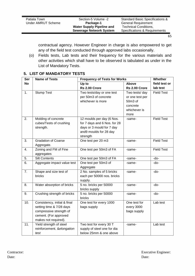
Patiala Town Under AMRUT Scheme
Section-5 Volume -2 Package-1
Water Supply Pipeline and Sewerage Network System
Standard Basic Specifications & General Requirement Technical Conditions, Specifications & Requirements
65
Contractor:
Date:
Executive Engineer:
Date:
contractual agency. However Engineer in charge is also empowered to get
any of the field test conducted through approved labs occasionally.
(o) Fields tests, Lab tests and their frequency for the various materials and
other activities which shall have to be observed is tabulated as under in the
List of Mandatory Tests.
5. LIST OF MANDATORY TESTS
Ser
No
Name of Tests Frequency of Tests for Works Whether
field test or
lab test
Up to
Rs 2.00 Crore
Above
Rs 2.00 Crore
1. Slump Test Two tests/day or one test
per 50m3 of concrete
whichever is more
Two tests/ day
or one test per
50m3 of
concrete
whichever is
more
Field Test
2. Molding of concrete
cubes/Tests of crushing
strength.
12 moulds per day (6 Nos.
for 7 days and 6 Nos. for 28
days or 3 mould for 7 day
and9 moulds for 28 day
strength
-same- Field Test
3. Gradation of Coarse
Aggregate.
One test per 20 m3 -same- Field Test
4. Zoning and FM of Fine
aggregates
One test per 50m3 of FA -same- Field Test
5. Silt Contents One test per 50m3 of FA -same- -do-
6. Aggregate impact value test One test per 50m3 of
Aggregate
-same- -do-
7. Shape and size test of
bricks
2 No. samples of 5 bricks
each per 50000 nos. bricks
supply.
-same- -do-
8. Water absorption of bricks 5 no. bricks per 50000
bricks supply
-same- -do-
9. Crushing strength of bricks 5 no. bricks per 50000
bricks
-same- -do-
10. Consistency, initial & final
setting time & 7/28 days
compressive strength of
cement. (For approved
makes not required).
One test for every 1000
bags supply
One test for
every 3000
bags supply
Lab test
11. Yield strength of steel
reinforcement. &elongation
test
Two test for every 30 T
supply of steel one for dia
below 25mm & one above
-same- Lab test

Patiala Town Under AMRUT Scheme
Section-5 Volume -2 Package-1
Water Supply Pipeline and Sewerage Network System
Standard Basic Specifications & General Requirement Technical Conditions, Specifications & Requirements
66
Contractor:
Date:
Executive Engineer:
Date:
6. INSPECTION OF WORKS
A necessary testing kit for the inspection of work made available as required by
the Engineer-in-charge.
During the inspection if any work or its portion is found to be substandard it shall
have to be dismantled and constructed by the contractual agency at his own cost.
7. WORK TO BE EXECUTED IN ACCORDANCE WITH SPECIFICATIONS
DRAWINGS & ORDER
The contractor shall execute the whole and every part of the work in the most
systematic and Workman like manner both as regards materials and labour and
otherwise in every respect in strict accordance with the Punjab PWD
specifications latest edition/IS codes or orders. The contractor shall also follow
exactly, fully and faithfully to the designs, drawings and instructions in writing
relating to the work assigned by the Engineer-in-Charge. The contractor shall be
furnished free of charge three copies of all such drawings and one copy of
agreement with complete documents. He shall, if so required, be entitled at his
own expenses to make or cause to be made copies of the drawings, designs,
specifications and instructions as aforesaid.
8. PREAMBLE TO BILL OF QUANTITIES (CIVIL PORTION)
(a) The items of RCC given above cover both cast in – Situ and pre-cast work,
the pre-cast work including the cost of hoisting and fixing in position,
complete in all respects Pre-cast panels shall be provided with smooth
finishing at no extra cost.
(b) Clean washed coarse sand having fineness modules, of 2.0 to 3.4 shall be
used as per latest IS code 383.
(c) Steel shuttering shall be used for slabs/columns and other superstructure
components and nothing extra shall be paid over and above the quoted
rates.
25mm dia.
12. Cold bend test of Steel Two tests for each supply -same- Field test

Patiala Town Under AMRUT Scheme
Section-5 Volume -2 Package-1
Water Supply Pipeline and Sewerage Network System
Standard Basic Specifications & General Requirement Technical Conditions, Specifications & Requirements
67
Contractor:
Date:
Executive Engineer:
Date:
9. LIST OF INDIAN STANDARDS
(Latest Edition)
(Material & Execution of Works etc.)
Ser
No IS Code Description
1. IS 3114 Laying of CI pipes
2. IS 1536 CI S/S pipe
3. IS 5382 Rubber gaskets
4. IS 5330 Anchor or thrust blocks
5. IS 8329 CI ductile pipes S/S
6. IS 12820 Rubber gaskets
7. IS 9523 Fittings
8. IS 8329 Testing of Ductile Iron pipe
9. IS 12288 Laying of ductile iron pipes
10. IS 780 CI Plain ended SV and d/f SV
11. IS 2685 Selection, installation & O & M of SV
12. IS 5531 CI P/E specials
13. IS 1538 CI socketed or flanged specials
14. IS1363 Part I & III Nut & Bolts
15. IS638 (2nd
Rev.) Rubber Insertion Joints
16. IS 210 Material of CI specials
17. IS 909 FH (SV type)
18. IS 3950 CI surface box for SV
19. IS 782 Caulking lead
20. IS1239 Mild steel tubes, tubular and other wrought steel fitting
(Part I and II)
21. IS 1538 Cast iron fitting for pressure pipes for Water sewage
(Part I – xxiii)
22. IS 2906 Sluice valve for water works purpose (350 to 1200mm size)
Note: Any item in the execution of works or material not covered in the above
list shall be governed by the relevant Indian Standard CODE, PWD
Specifications or prescribed specifications or orders as per the decision of
Engineer-in-Charge.
Related Documents