FLÄKT WOODS LIMITED FANS IN FIRE SAFETY SMOKE CONTROL BY PRESSURISATION By: J.A. WILD, C.ENG; F.I.MECH.E. A SIMPLIFIED APPROACH TO PRESSURISATION CALCULATIONS © Copyright 2000 Fläkt Woods Limted England.

Staircase Pressurization Calculations Procedure
Oct 21, 2015
Welcome message from author
This document is posted to help you gain knowledge. Please leave a comment to let me know what you think about it! Share it to your friends and learn new things together.
Transcript
FLÄKT WOODS LIMITED
FANS IN FIRE SAFETY
SMOKE CONTROLBY
PRESSURISATION
By: J.A. WILD, C.ENG; F.I.MECH.E.
A SIMPLIFIED APPROACH TO PRESSURISATION CALCULATIONS
© Copyright 2000 Fläkt Woods Limted England.

2
This document has been produced as a general guide and its contents should not be construed as anyrepresentation on our part as to the quality or fitness of our products for any particular purpose, nor asproviding advice on the design of fire and smoke control systems. You are recommended to consult yourprofessional advisers on matters relating to the design and installation of any such systems.

3
SMOKE CONTROL BY PRESSURISATION
SUMMARY
Woods Technical Paper - WTP41 - 1998 Edition - traces the development of Pressurisa-tion Systems in the control of Fire Smoke In Buildings.
Based on the revised British Standard - BS5588: Part 4: 1998, Code of practice for smokecontrol using pressure differentials it outlines the requirement of both the various systemsdetailed in this Code Of Practice and the fans required to power these systems.
This Paper supports WTP41 and is intended to assist engineers in designing pressurisa-tion systems. It examines in detail the fan engineering problems raised by the new Code,and suggests a simplified method for quickly estimating the air volume rates required -useful at the early stage of the project.
1.0 INTRODUCTION
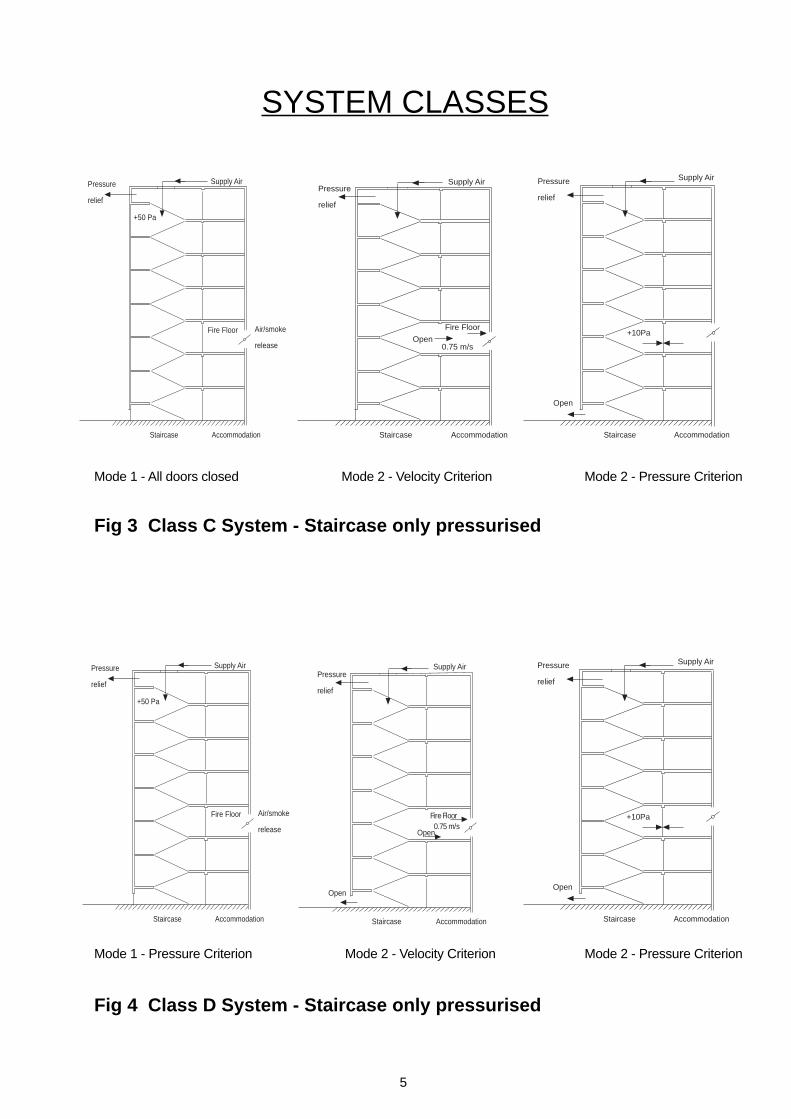
BS5588: Part 4: 1998, brought together the pressurisation requirement of earlier CodesOf Practice, (BS5588 Part 4: 1978 & BS5588 Part 5: 1991) and added three additionalscenarios - making a total of five classes of pressurisation systems.
These five classes of system are outlined in Table 1 below - detailed in Figs. 1 to 5.
TABLE 1 - CLASS OF SYSTEMS
System Area of Use Requirement of System Class A Residential, sheltered housing To maintain pressure of 50Pa when all
& Buildings with three door doors are closedprotection. To maintain velocity of 0.75m/s
through open Fire Floor DoorDoor Status - See Fig 1
B Protection of firefighting shafts To maintain pressure at 50Pa whenall doors are closedTo maintain velocity of 2.0m/s throughopen Fire Floor DoorDoor Status - See Fig 2
C Commercial premises (using To maintain pressure of 50Pa with allsimultaneous evacuation) doors closed
To maintain velocity of 0.75m/s throughopen Fire Floor DoorTo maintain pressure of 10Pa with finalExit Door OpenDoor Status - See Fig. 3
D Hotels, hostels and institutional-type As above (C)buildings, excluding those in Class A Door Status - See Fig. 4
E Buildings using phased evacuation As above (C)Door Status - See Fig. 5

4
Mode 1 - Pressure criterion all doors closed Mode 2 - Velocity Criterion
Fig 1 Class A System - Staircase only
Staircase Accommodation
Fire Floor
Supply Air
50 Pa
Pressure
relief
Air/smokerelease
Staircase Accommodation
Fire FloorOpen
0.75 m/s
Supply Air
Air/smokerelease
Pressure
relief
Staircase LiftLobby
Accommodation
Supply Air
+ 50 PaPressure
relief
Fire FloorAir/smoke
Release
Staircase LiftLobby
Accommodation
2.0 m/s
Open
FireFightingStairs
Supply Air
Fire Floor
Open
Air/smokerelease
Pressure
relief
SYSTEM CLASSES
Mode 1 - Pressure criterion all doors closed Mode 3 Fire Fighting - Velocity Criterion
Fig 2 Class B System - Fire Fighting Stairs and Lift
5
Fig 3 Class C System - Staircase only pressurised
SYSTEM CLASSES
Mode 1 - All doors closed Mode 2 - Velocity Criterion Mode 2 - Pressure Criterion
Staircase Accommodation
Fire Floor
Open0.75 m/s
Supply AirPressure
relief
Staircase Accommodation
Open
Supply AirPressure
relief
+10Pa
Staircase Accommodation
+50 Pa
Pressure
relief
Fire Floor
Supply Air
Air/smoke
release
Staircase Accommodation
Open
Supply AirPressure
relief
+10Pa
Staircase Accommodation
+50 Pa
Pressure
relief
Fire Floor
Supply Air
Air/smoke
release
Staircase Accommodation
Fire Floor
Open0.75 m/s
Supply AirPressure
relief
Open
Mode 1 - Pressure Criterion Mode 2 - Velocity Criterion Mode 2 - Pressure Criterion
Fig 4 Class D System - Staircase only pressurised

6
Staircase Accommodation
+50 Pa
Pressure
relief
Fire Floor
Supply Air
Air/smoke
release
SYSTEM CLASSES
Mode 1 - Pressure Criterion
Staircase Accommodation
Fire FloorOpen
0.75 m/s
Open
Open
Supply AirPressure
relief
Staircase Accommodation
Open
+10Pa
Open
Open
Supply AirPressure
relief
Fire Floor
Mode 2 - Pressure Criterion Mode 2 - Velocity Criterion
Fig 5 - Class E Systems - Staircase only pressurised
7
The requirements of these Fire Pressurisation System classes produce a wide range ofvariation in the leakage paths from the pressurised spaces. Fortunately, a number ofthese leakage paths are common to more than one system, and hence a degree ofstandardisation becomes possible. These common features are listed below:-
1. ALL CLASSES of system have a PRESSURE CRITERION of 50Pa with ALLDOORS CLOSED (Mode 1)
2. CLASS A SYSTEMS - have a velocity criterion of 0.75m/s through the OPENFIRE DOOR (Mode 2) with ALL other DOORS CLOSED.
3. CLASS B SYSTEMS - have a VELOCITY CRITERION of 2.0m/s through theOPEN FIRE FLOOR DOOR (Mode 3) with the FINAL EXIT DOOR OPEN
CLASS B SYSTEMS - have a PRESSURE CRITERION of 50Pa in the FIREFIGHTING LIFT at all times.
4. CLASS C SYSTEMS - have a PRESSURE CRITERION of 10Pa with the FINALEXIT DOOR OPEN, AND a VELOCITY CRITERION of 0.75m/s through theOPEN FIRE FLOOR DOOR with ALL OTHER DOORS CLOSED (Mode 2).
5. CLASS D SYSTEMS - have a PRESSURE CRITERION of 10Pa AND aVELOCITY CRITERION of 0.75 m/s through the OPEN FIRE FLOOR DOORwith the FINAL EXIT DOOR OPEN (Mode 2)
6. CLASS E SYSTEMS - have a PRESSURE CRITERION of 10Pa with the FINALEXIT and TWO NON FIRE FLOOR DOORS OPEN, AND a VELOCITYCRITERION of 0.75 m/s through the OPEN FIRE FLOOR DOOR with the FINALEXIT and ONE NON FIRE FLOOR DOOR OPEN
7. LIFT SHAFTS - have a top vent aperture of 0.1m2 in addition to the lift doors.
2.0 BASIC PRINCIPLES & FAN ENGINEERING
The two BASIC PRINCIPLES which control the design and ultimately the satisfactoryfunctioning of a PRESSURISATION SYSTEM for Smoke Control were defined by J.H.Klote as being:-
(1) That airflow can control smoke movement if the average VELOCITY is of sufficientmagnitude (VELOCITY CRITERION)
(2) That PRESSURE differences across barriers can act to control smoke movement(PRESSURE CRITERION)
The VELOCITY CRITERION usually, but not always, establishes both the air quantityrequirement and the airflow patterns for the system, where NATURAL EXHAUST fromthe fire floor is used.
8
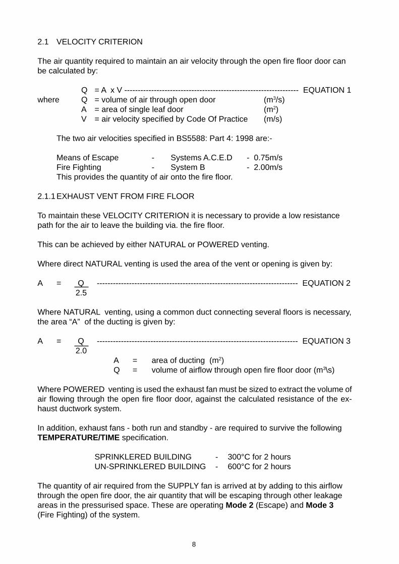
2.1 VELOCITY CRITERION
The air quantity required to maintain an air velocity through the open fire floor door canbe calculated by:
Q = A x V ----------------------------------------------------------------- EQUATION 1where Q = volume of air through open door (m3/s)
A = area of single leaf door (m2)V = air velocity specified by Code Of Practice (m/s)
The two air velocities specified in BS5588: Part 4: 1998 are:-
Means of Escape - Systems A.C.E.D - 0.75m/sFire Fighting - System B - 2.00m/sThis provides the quantity of air onto the fire floor.
2.1.1EXHAUST VENT FROM FIRE FLOOR
To maintain these VELOCITY CRITERION it is necessary to provide a low resistancepath for the air to leave the building via. the fire floor.
This can be achieved by either NATURAL or POWERED venting.
Where direct NATURAL venting is used the area of the vent or opening is given by:
A = Q --------------------------------------------------------------------------- EQUATION 22.5
Where NATURAL venting, using a common duct connecting several floors is necessary,the area “A” of the ducting is given by:
A = Q --------------------------------------------------------------------------- EQUATION 32.0
A = area of ducting (m2)Q = volume of airflow through open fire floor door (m3\s)
Where POWERED venting is used the exhaust fan must be sized to extract the volume ofair flowing through the open fire floor door, against the calculated resistance of the ex-haust ductwork system.
In addition, exhaust fans - both run and standby - are required to survive the followingTEMPERATURE/TIME specification.
SPRINKLERED BUILDING - 300°C for 2 hoursUN-SPRINKLERED BUILDING - 600°C for 2 hours
The quantity of air required from the SUPPLY fan is arrived at by adding to this airflowthrough the open fire door, the air quantity that will be escaping through other leakageareas in the pressurised space. These are operating Mode 2 (Escape) and Mode 3(Fire Fighting) of the system.
9
2.2 PRESSURE CRITERIONThe quantity of air required to maintain the PRESSURE CRITERION can be calculatedby:-
Q = 0.83 AE p0.5 ------------------------------------------------------ EQUATION 4
where Q = volume flow of air required (m3/s)A
E= effective leakage area (m2) - (See Table 2)
p = pressure specified by Code Of Practice (Pa)
This will deal with the known leakage from the pressurised space. The unknown leak-age’s are allowed for by adding 50% - recommended in the Code Of Practice - to theresulting air quantity. Hence Equation 4 becomes:-
Q = 0.83 AE p0.5 x 1.50 --------------------------------------------- EQUATION 5
There are two pressure criterion specified in BS5588: Part 4: 1998
All Doors Closed - 50PaCertain Doors Open - 10Pa
Hence to make this equation work we need to establish AE - the effective leakage area
from the pressurised space. There are three possible open/door configurations.
1. For single openingsA
E= A
1 - EQUATION 6
2 For several openings in parallelA
E= A
1 + A
2 + A
3 + A
4 - EQUATION 7
3 For several openings in seriesAE = 1 1 1 1
A1
2 A2
2 A32 A
42 - EQUATION 8
These open/door configurations are discussed in more detail in WTP41
2.2.1 PRESSURE RELIEF DAMPER
Generally the air volume required to achieve the VELOCITY CRITERION or PRES-SURE CRITERION when doors are OPEN exceed that necessary to establish thePRESSURE CRITERION when all doors are CLOSED (DETECTION PHASE) .
To prevent the build-up of excessive pressures in the pressurised space (escape routes)when all doors are CLOSED (+ 60Pa in BS5588:Part 4:1998), a pressure relief damperis required between the pressurised space and an area of zero pressure (usually out-side the building).
[ ] - 0.5
+ + +
10
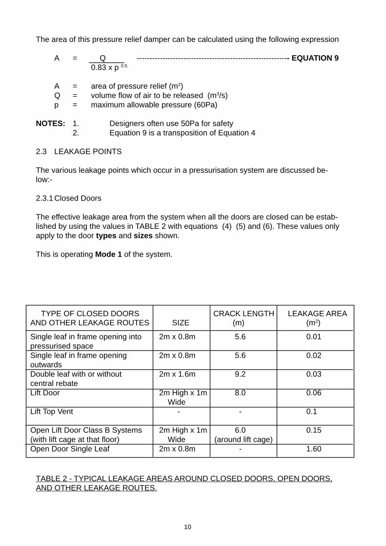
The area of this pressure relief damper can be calculated using the following expression
A = Q ----------------------------------------------------------- EQUATION 90.83 x p 0.5
A = area of pressure relief (m2)Q = volume flow of air to be released (m3/s)p = maximum allowable pressure (60Pa)
NOTES: 1. Designers often use 50Pa for safety2. Equation 9 is a transposition of Equation 4
2.3 LEAKAGE POINTS
The various leakage points which occur in a pressurisation system are discussed be-low:-
2.3.1Closed Doors
The effective leakage area from the system when all the doors are closed can be estab-lished by using the values in TABLE 2 with equations (4) (5) and (6). These values onlyapply to the door types and sizes shown.
This is operating Mode 1 of the system.
TABLE 2 - TYPICAL LEAKAGE AREAS AROUND CLOSED DOORS, OPEN DOORS,AND OTHER LEAKAGE ROUTES.
TYPE OF CLOSED DOORS CRACK LENGTH LEAKAGE AREAAND OTHER LEAKAGE ROUTES SIZE (m) (m2)
Single leaf in frame opening into 2m x 0.8m 5.6 0.01pressurised spaceSingle leaf in frame opening 2m x 0.8m 5.6 0.02outwardsDouble leaf with or without 2m x 1.6m 9.2 0.03central rebateLift Door 2m High x 1m 8.0 0.06
WideLift Top Vent - - 0.1
Open Lift Door Class B Systems 2m High x 1m 6.0 0.15(with lift cage at that floor) Wide (around lift cage)Open Door Single Leaf 2m x 0.8m - 1.60
11
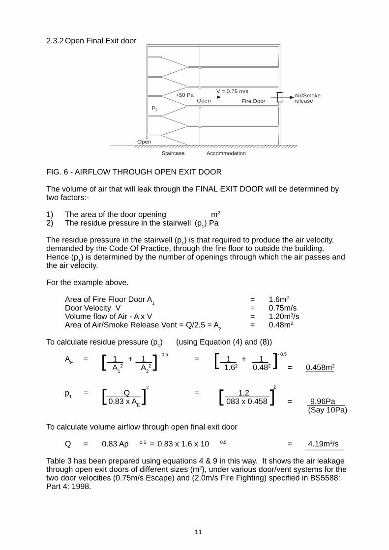
2.3.2 Open Final Exit door
FIG. 6 - AIRFLOW THROUGH OPEN EXIT DOOR
The volume of air that will leak through the FINAL EXIT DOOR will be determined bytwo factors:-
1) The area of the door opening m2
2) The residue pressure in the stairwell (p1) Pa
The residue pressure in the stairwell (p1) is that required to produce the air velocity,demanded by the Code Of Practice, through the fire floor to outside the building.Hence (p1) is determined by the number of openings through which the air passes andthe air velocity.
For the example above.
Area of Fire Floor Door A1
= 1.6m2
Door Velocity V = 0.75m/sVolume flow of Air - A x V = 1.20m3/sArea of Air/Smoke Release Vent = Q/2.5 = A
2= 0.48m2
To calculate residue pressure (p1) (using Equation (4) and (8))
AE = 1 + 1 = 1 + 1 A1
2 A22 1.62 0.482 = 0.458m2
p1 = Q = 1.2 0.83 x A
E 083 x 0.458 = 9.96Pa
(Say 10Pa)
To calculate volume airflow through open final exit door
Q = 0.83 Ap 0.5 = 0.83 x 1.6 x 10 0.5 = 4.19m3/s
Table 3 has been prepared using equations 4 & 9 in this way. It shows the air leakagethrough open exit doors of different sizes (m2), under various door/vent systems for thetwo door velocities (0.75m/s Escape) and (2.0m/s Fire Fighting) specified in BS5588:Part 4: 1998.
[ ]
[ ]
Staircase Accommodation
+50 Pa
p1
Open
V = 0.75 m/sAir/SmokereleaseFire DoorOpen
[ ]
[ ]2
- 0.5
2
- 0.5
12
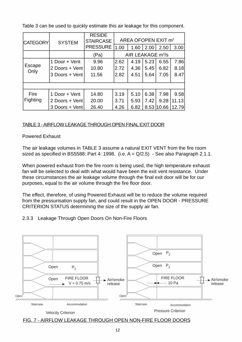
Table 3 can be used to quickly estimate this air leakage for this component.
CATEGORY SYSTEM
TABLE 3 - AIRFLOW LEAKAGE THROUGH OPEN FINAL EXIT DOOR
Powered Exhaust
The air leakage volumes in TABLE 3 assume a natural EXIT VENT from the fire roomsized as specified in BS5588: Part 4: 1998. (i.e. A = Q/2.5) - See also Paragraph 2.1.1.
When powered exhaust from the fire room is being used, the high temperature exhaustfan will be selected to deal with what would have been the exit vent resistance. Underthese circumstances the air leakage volume through the final exit door will be for ourpurposes, equal to the air volume through the fire floor door.
The effect, therefore, of using Powered Exhaust will be to reduce the volume requiredfrom the pressurisation supply fan, and could result in the OPEN DOOR - PRESSURECRITERION STATUS determining the size of the supply air fan.
2.3.3 Leakage Through Open Doors On Non-Fire Floors
Staircase Accommodation
P2
Open
FIRE FLOOR
Open
Open
Staircase
P2
Open
FIRE FLOOR
Open
Open P2
Pressure CriterionVelocity Criterion
V = 0.75 m/sAir/smokerelease
Air/smokerelease10 Pa
Accommodation
FIG. 7 - AIRFLOW LEAKAGE THROUGH OPEN NON-FIRE FLOOR DOORS
AREA OFOPEN EXIT m2
1.00 1.60 2.00 2.50 3.00
(Pa) AIR LEAKAGE m3/s 1 Door + Vent 9.96 2.62 4.19 5.23 6.55 7.86 2 Doors + Vent 10.80 2.72 4.36 5.45 6.82 8.18 3 Doors + Vent 11.56 2.82 4.51 5.64 7.05 8.47
1 Door + Vent 14.80 3.19 5.10 6.38 7.98 9.58 2 Doors + Vent 20.00 3.71 5.93 7.42 9.28 11.13 3 Doors + Vent 26.40 4.26 6.82 8.53 10.66 12.79
FireFighting
EscapeOnly
RESIDESTAIRCASEPRESSURE
13
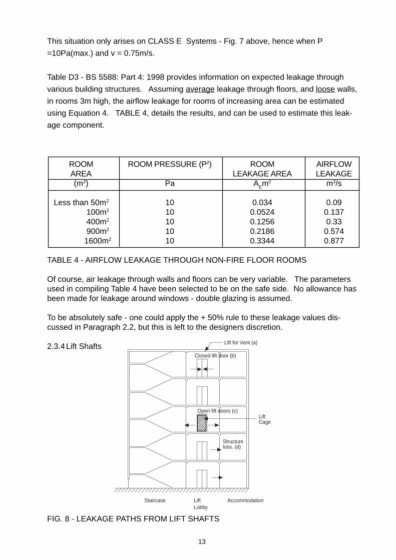
This situation only arises on CLASS E Systems - Fig. 7 above, hence when P
=10Pa(max.) and v = 0.75m/s.
Table D3 - BS 5588: Part 4: 1998 provides information on expected leakage through
various building structures. Assuming average leakage through floors, and loose walls,
in rooms 3m high, the airflow leakage for rooms of increasing area can be estimated
using Equation 4. TABLE 4, details the results, and can be used to estimate this leak-
age component.
ROOM ROOM PRESSURE (P2) ROOM AIRFLOWAREA LEAKAGE AREA LEAKAGE(m2) Pa AEm2 m3/s
Less than 50m2 10 0.034 0.09100m2 10 0.0524 0.137400m2 10 0.1256 0.33900m2 10 0.2186 0.574
1600m2 10 0.3344 0.877
TABLE 4 - AIRFLOW LEAKAGE THROUGH NON-FIRE FLOOR ROOMS
Of course, air leakage through walls and floors can be very variable. The parametersused in compiling Table 4 have been selected to be on the safe side. No allowance hasbeen made for leakage around windows - double glazing is assumed.
To be absolutely safe - one could apply the + 50% rule to these leakage values dis-cussed in Paragraph 2.2, but this is left to the designers discretion.
2.3.4 Lift Shafts
FIG. 8 - LEAKAGE PATHS FROM LIFT SHAFTS
Staircase LiftLobby
Accommodation
Closed lift door (b)
Open lift doors (c)
Structureloss. (d)
Lift for Vent (a)
LiftCage
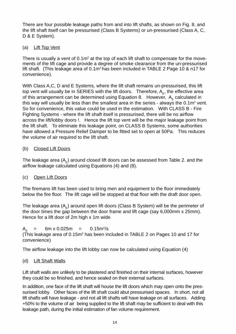
14
There are four possible leakage paths from and into lift shafts, as shown on Fig. 8, andthe lift shaft itself can be pressurised (Class B Systems) or un-pressurised (Class A, C,D & E System).
(a) Lift Top Vent
There is usually a vent of 0.1m2 at the top of each lift shaft to compensate for the move-ments of the lift cage and provide a degree of smoke clearance from the un-pressurisedlift shaft. (This leakage area of 0.1m2 has been included in TABLE 2 Page 10 & n17 forconvenience).
With Class A,C, D and E Systems, where the lift shaft remains un-pressurised, this lifttop vent will usually be in SERIES with the lift doors. Therefore, AE, the effective areaof this arrangement can be determined using Equation 8. However, AE calculated inthis way will usually be less than the smallest area in the series - always the 0.1m2 vent.So for convenience, this value could be used in the estimation. With CLASS B - FireFighting Systems - where the lift shaft itself is pressurised, there will be no airflowacross the lift/lobby doors !. Hence the lift top vent will be the major leakage point fromthe lift shaft. To eliminate this leakage point, on CLASS B Systems, some authoritieshave allowed a Pressure Relief Damper to be fitted set to open at 50Pa. This reducesthe volume of air required to the lift shaft.
(b) Closed Lift Doors
The leakage area (AE) around closed lift doors can be assessed from Table 2. and theairflow leakage calculated using Equations (4) and (8).
(c) Open Lift Doors
The firemans lift has been used to bring men and equipment to the floor immediatelybelow the fire floor. The lift cage will be stopped at that floor with the draft door open.
The leakage area (AE) around open lift doors (Class B System) will be the perimeter ofthe door times the gap between the door frame and lift cage (say 6,000mm x 25mm).Hence for a lift door of 2m high x 1m wide
AE = 6m x 0.025m = 0.15m2/s(This leakage area of 0.15m2 has been included in TABLE 2 on Pages 10 and 17 forconvenience)
The airflow leakage into the lift lobby can now be calculated using Equation (4)
(d) Lift Shaft Walls
Lift shaft walls are unlikely to be plastered and finished on their internal surfaces, howeverthey could be so finished, and hence sealed on their external surfaces.
In addition, one face of the lift shaft will house the lift doors which may open onto the pres-surised lobby. Other faces of the lift shaft could abut pressurised spaces. In short, not alllift shafts will have leakage - and not all lift shafts will have leakage on all surfaces. Adding+50% to the volume of air being supplied to the lift shaft may be sufficient to deal with thisleakage path, during the initial estimation of fan volume requirement.
15
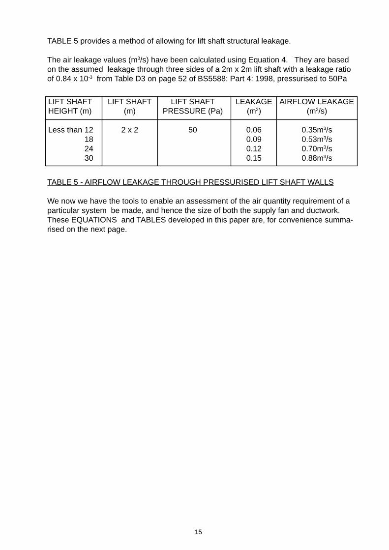
TABLE 5 provides a method of allowing for lift shaft structural leakage.
The air leakage values (m3/s) have been calculated using Equation 4. They are basedon the assumed leakage through three sides of a 2m x 2m lift shaft with a leakage ratioof 0.84 x 10⁻³ from Table D3 on page 52 of BS5588: Part 4: 1998, pressurised to 50Pa
TABLE 5 - AIRFLOW LEAKAGE THROUGH PRESSURISED LIFT SHAFT WALLS
We now we have the tools to enable an assessment of the air quantity requirement of aparticular system be made, and hence the size of both the supply fan and ductwork.These EQUATIONS and TABLES developed in this paper are, for convenience summa-rised on the next page.
LIFT SHAFT LIFT SHAFT LIFT SHAFT LEAKAGE AIRFLOW LEAKAGEHEIGHT (m) (m) PRESSURE (Pa) (m2) (m2/s)
Less than 12 2 x 2 50 0.06 0.35m3/s18 0.09 0.53m3/s24 0.12 0.70m3/s30 0.15 0.88m3/s
16
[ ] + +
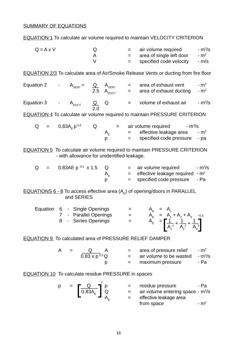
SUMMARY OF EQUATIONS
EQUATION 1 To calculate air volume required to maintain VELOCITY CRITERION
Q = A x V Q = air volume required - m3/sA = area of single left door - m2
V = specified code velocity - m/s
EQUATION 2/3 To calculate area of Air/Smoke Release Vents or ducting from fire floor
Equation 2 - AVENT
= Q AVENT
= area of exhaust vent - m2
2.5 ADUCT
= area of exhaust ducting - m2
Equation 3 - ADUCT
Q Q = volume of exhaust air - m3/s 2.0
EQUATION 4 To calculate air volume required to maintain PRESSURE CRITERION
Q = 0.83AE p 0.5 Q = air volume required - m3/s
AE
= effective leakage area - m2
p = specified code pressure - pa
EQUATION 5 To calculate air volume required to maintain PRESSURE CRITERION - with allowance for unidentified leakage.
Q = 0.83AE p 0.5 x 1.5 Q = air volume required - m3/sA
E= effective leakage required - m2
p = specified code pressure - Pa
EQUATIONS 6 - 8 To access effective area (AE) of opening/doors in PARALLEL
and SERIES
Equation 6 - Single Openings = AE
= A1
7 - Parallel Openings = AE
= A1 + A
2 + A
3-
8 - Series Openings = AE
= 1 1 1 A
12 A
22 A
32
EQUATION 9 To calculated area of PRESSURE RELIEF DAMPER
A = Q A = area of pressure relief - m2
0.83 x p 0.5 Q = air volume to be wasted - m3/sp = maximum pressure - Pa
EQUATION 10 To calculate residue PRESSURE in spaces
p = Q p = residue pressure - Pa0.83A
EQ = air volume entering space - m3/sA
E= effective leakage area
from space - m2
[ ]2
0.5

17
ROOM ROOM PRESSURE (p2) ROOM AIRFLOWAREA PRESSURE (p2) LEAKAGE AREA LEAKAGE(m2) Pa m2 m3/s
Less than 50m2 10 0.034 0.09100m2 10 0.0524 0.137400m2 10 0.1256 0.33900m2 10 0.2186 0.574
1600m2 10 0.3344 0.877
SUMMARY OF TABLES
TABLE 2 - TYPICAL LEAKAGE AREAS AROUND CLOSED DOORS, OPENDOORS AND OTHER LEAKAGE ROUTES
TABLE 3 - AIRFLOW LEAKAGE THROUGH OPEN FINAL EXIT FLOOR
TABLE 4 - AIRFLOW LEAKAGE THROUGH NONE FIRE FLOOR DOORS
TABLE 5 - AIRFLOW LEAKAGE THROUGH PRESSURISED LIFT SHAFT WALLS
LIFT SHAFT LIFT SHAFT LIFT SHAFT LEAKAGE AIRFLOW LEAKAGEHEIGHT (m) (m) PRESSURE (Pa) (m2) (m2/s)
Less than 12 2 x 2 50 0.06 0.35m3/s18 0.09 0.53m3/s24 0.12 0.70m3/s30 0.15 0.88m3/s
TYPE OF CLOSED DOOR CRACK LENGTH LEAKAGE AREAAND OTHER LEAKAGE ROUTES SIZE (m) (m)
Single Leaf in Frame Opening into 2m x 800mm 5.6 0.01Pressurised SpaceSingle Leaf in Frame Opening 2m x 800mm 5.6 0.02OutwardsDouble Leaf with or without 2m x 1.6m 9.2 0.03Central RebateLift Door 2m High x 1m 8.0 0.06
WideLift Top Vent - - 0.1
Open Lift Door Class B Systems 2m High x 1m 6.0 0.15 Wide
Open Door Single Leaf 2m x 0.8m - 1.60
AREA OFOPEN EXIT m2
1.00 1.60 2.00 2.50 3.00
(Pa) AIR LEAKAGE m3/s 1 Door + Vent 9.96 2.62 4.19 5.23 6.55 7.86 2 Doors + Vent 10.80 2.72 4.36 5.45 6.82 8.18 3 Doors + Vent 11.56 2.82 4.51 5.64 7.05 8.47
1 Door + Vent 14.80 3.19 5.10 6.38 7.98 9.58 2 Doors + Vent 20.00 3.71 5.93 7.42 9.28 11.13 3 Doors + Vent 26.40 4.26 6.82 8.53 10.66 12.79
FireFighting
EscapeOnly
RESIDESTAIRCASEPRESSURE
CATEGORY SYSTEM
18
3. WORKED EXAMPLES
A complete and detailed calculation procedure with worked examples is outlined inBS5588: Part 4: 1998. Designers should follow this approach when seeking approvalfor their schemes.
The examples in this paper utilise the “tools” described in Paragraph 2. This muchsimpler method developed from procedures created and used by Mr. C. H. Moss is veryuseful for the initial sizing and selection of the supply air fans. It will always tend toover-estimate the air supply requirements (See WTP41).
The examples cover each of the five pressurisation system classes detailed in BS5588:Part 4: 1998 and include between them, all the system elements and leakage pathsdiscussed in Paragraphs 1 & 2. They assumed NATURAL EXHAUST from the FIREFLOOR. For convenience and clarity the EQUATIONS and TABLES used in theseexamples are referenced in the Right-hand Column of each page.
The Code Of Practice suggests that an allowance is added to the air quantity require-ments calculated to cover any airflow leakage of ductwork.
Sheet metal Ductwork - + 15%Builders Work Ducts - + 25%
In this paper these allowances are left to the discretion of the Designers.

19
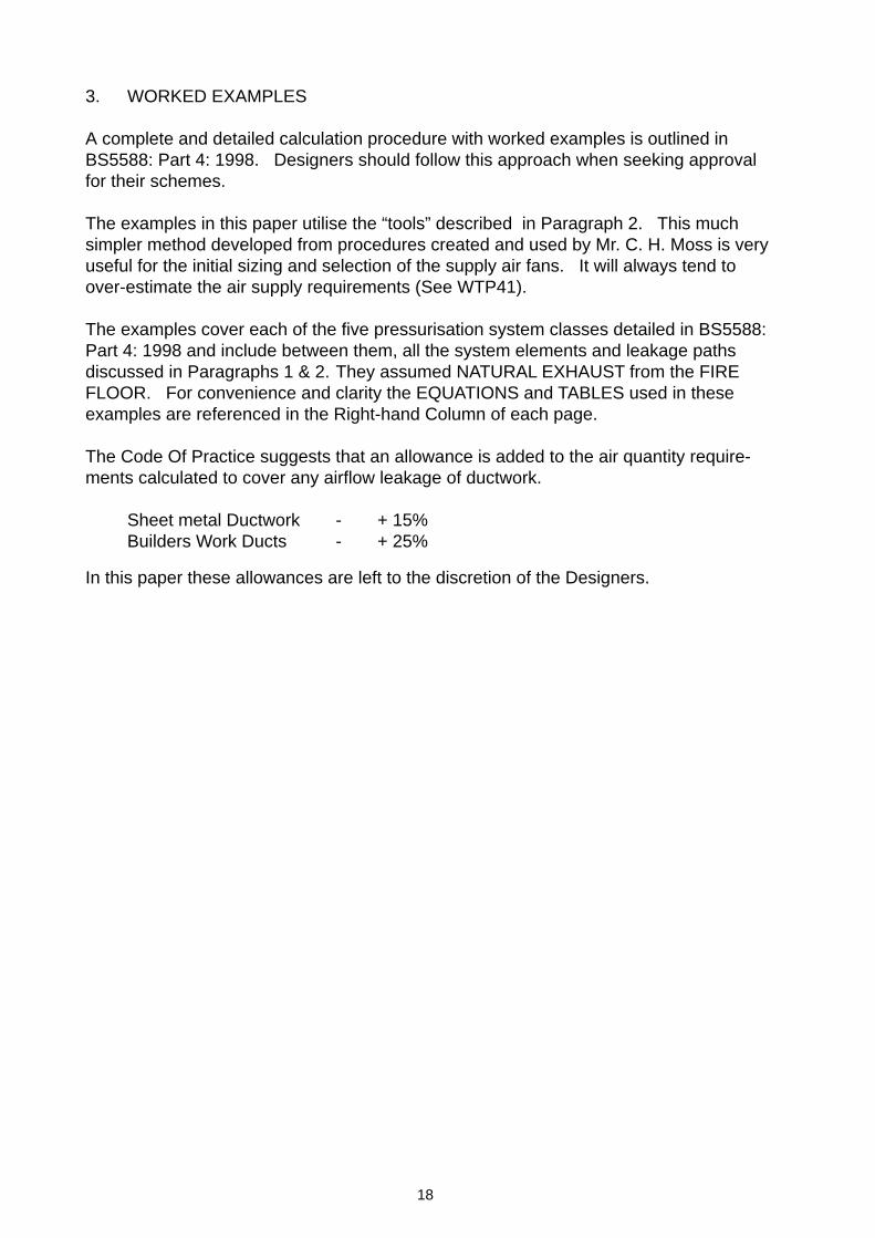
3.1 CLASS A SYSTEM - STAIRCASE ONLY PRESSURISED
Plan
MODE 1 - PRESSURE CRITERION REFERENCE
Leakage Area - 7 Single Doors opening in at 0.01m2 = 0.07m2
1 Double Door at exit = 0.03m2
AE = 0.10m2 - TABLE 2
Airflow required = Q = 0.83 AE p 0.5
= 0.83 x 0.1 x 50 0.5 = 0.586m3/s - EQUATION 4 + 50% = 0.880m3/s - EQUATION 5
Accommodation
Stairs
Staircase Accommodation
50 Pa
(all doors closed)
Fire FloorAir/smoke
release
Supply AirPressure
relief
20
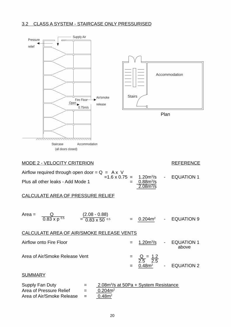
3.2 CLASS A SYSTEM - STAIRCASE ONLY PRESSURISED
MODE 2 - VELOCITY CRITERION REFERENCE
Airflow required through open door = Q = A x V =1.6 x 0.75 = 1.20m3/s - EQUATION 1
Plus all other leaks - Add Mode 1 = 0.88m3/s2.08m3/s
CALCULATE AREA OF PRESSURE RELIEF
Area = Q (2.08 - 0.88)= = 0.204m2 - EQUATION 9
CALCULATE AREA OF AIR/SMOKE RELEASE VENTS
Airflow onto Fire Floor = 1.20m3/s - EQUATION 1 above
Area of Air/Smoke Release Vent = Q = 1.22.5 2.5
= 0.48m2 - EQUATION 2
SUMMARY
Supply Fan Duty = 2.08m3/s at 50Pa + System ResistanceArea of Pressure Relief = 0.204m2
Area of Air/Smoke Release = 0.48m2
Staircase Accommodation
(all doors closed)
Fire FloorOpen
0.75m/s
Air/smoke
release
Supply AirPressure
relief
Accommodation
Stairs
Plan
0.83 x 50 0.50.83 x p 0.5

21
3.3 CLASS A SYSTEM - STAIRCASE & LOBBY PRESSURISED
MODE 1 - PRESSURE CRITERION REFERENCE
Stairs (Stairwell and lift lobbies pressurised - No airflow across stairwell/lobby door)
Leakage Area = 1 double door at exit = AE = 0.03m2 - TABLE 2
Airflow required = Q = 0.83 AE p 0.5
= 0.83 x 0.03 x 50 0.5 = 0.176m3/s - EQUATION 4+ 50% = 0.264m3/s - EQUATION 5
Lobbies
Leakage Area = 7 double doors to accommodation at 0.03 = 0.21m2 - TABLE 2
Lift top vent = 0.10m2
AE = 0.31m2
Airflow required = Q = 0.83 AE P 0.5
= 0.83 x 0.31 x 50 0.5 = 1.82 m3/s - EQUATION 4 + 50% = 2.73m3/s - EQUATION 5
MODE 1 Total airflow required - (0.264 + 2.73) = 2.994m3/s
(Say 3.0m3/s)
NOTE : 50% rule used for lift shaft leakage
Plan
Staircase LiftLobby
Accommodation
Fire Floor
+ 50 Pa
Supply Air
Air/smokerelease
Pressurerelease
Lift LiftLobby
Accom.
Stairs
22
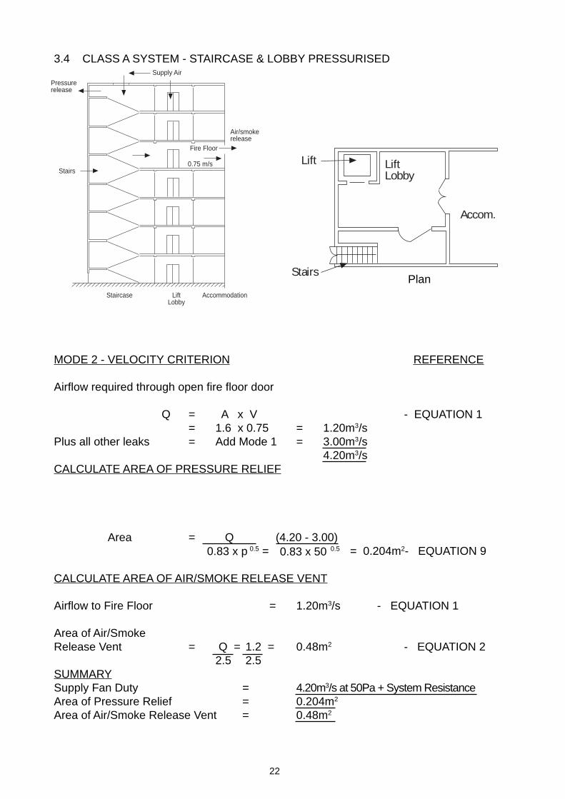
3.4 CLASS A SYSTEM - STAIRCASE & LOBBY PRESSURISED
MODE 2 - VELOCITY CRITERION REFERENCE
Airflow required through open fire floor door
Q = A x V - EQUATION 1= 1.6 x 0.75 = 1.20m3/s
Plus all other leaks = Add Mode 1 = 3.00m3/s4.20m3/s
CALCULATE AREA OF PRESSURE RELIEF
Area = Q (4.20 - 3.00) 0.5 = 0.5 = 0.204m2- EQUATION 9
CALCULATE AREA OF AIR/SMOKE RELEASE VENT
Airflow to Fire Floor = 1.20m3/s - EQUATION 1
Area of Air/SmokeRelease Vent = Q = 1.2 = 0.48m2 - EQUATION 2
2.5 2.5SUMMARYSupply Fan Duty = 4.20m3/s at 50Pa + System ResistanceArea of Pressure Relief = 0.204m2
Area of Air/Smoke Release Vent = 0.48m2
Lift LiftLobby
Accom.
Stairs
Staircase LiftLobby
Accommodation
Supply Air
Pressurerelease
0.75 m/sStairs
Fire Floor
Air/smokerelease
Plan
0.83 x 500.83 x p
23
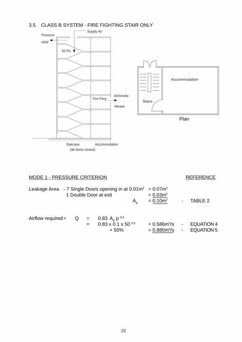
3.5 CLASS B SYSTEM - FIRE FIGHTING STAIR ONLY
MODE 1 - PRESSURE CRITERION REFERENCE
Leakage Area - 7 Single Doors opening in at 0.01m2 = 0.07m2
1 Double Door at exit = 0.03m2
AE = 0.10m2 - TABLE 2
Airflow required = Q = 0.83 AE p 0.5
= 0.83 x 0.1 x 50 0.5 = 0.586m3/s - EQUATION 4+ 50% = 0.880m3/s - EQUATION 5
Accommodation
Stairs
Staircase Accommodation
50 Pa
(all doors closed)
Fire FloorAir/smoke
release
Supply AirPressure
relief
Plan
24
0.83 x 50 0.5
3.6 CLASS B SYSTEM - FIRE FIGHTING STAIR ONLY
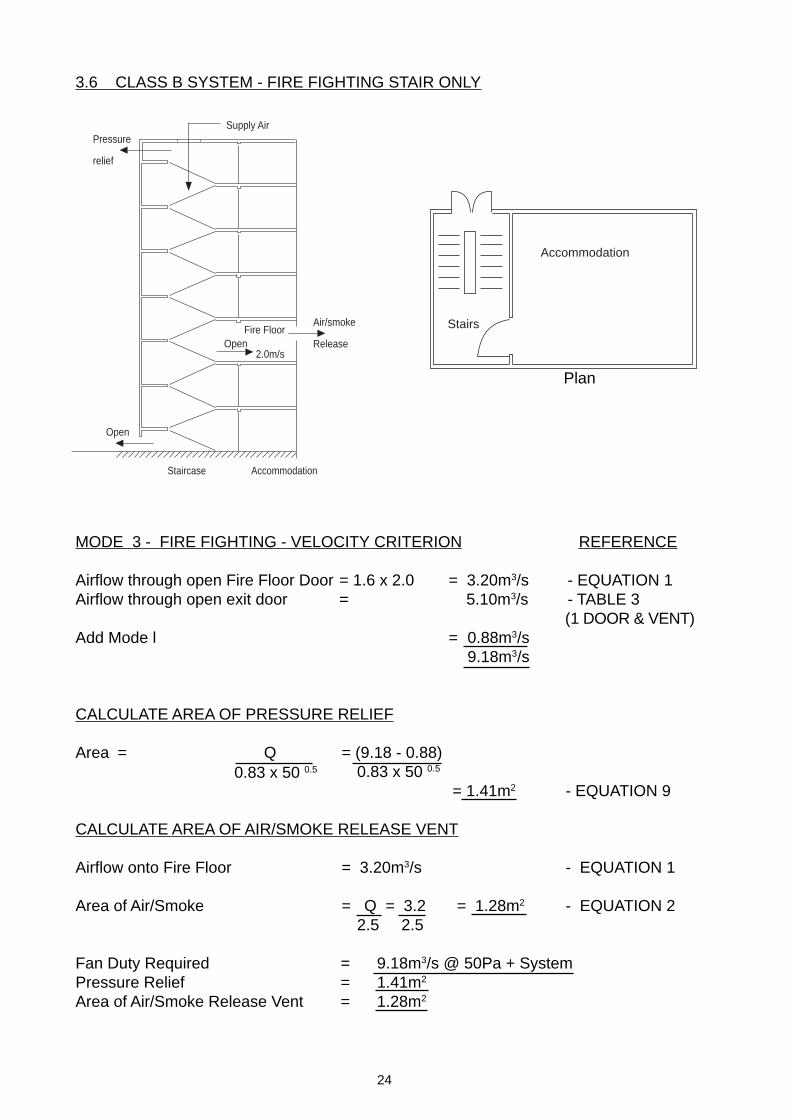
MODE 3 - FIRE FIGHTING - VELOCITY CRITERION REFERENCE
Airflow through open Fire Floor Door = 1.6 x 2.0 = 3.20m3/s - EQUATION 1Airflow through open exit door = 5.10m3/s - TABLE 3
(1 DOOR & VENT)Add Mode l = 0.88m3/s
9.18m3/s
CALCULATE AREA OF PRESSURE RELIEF
Area = Q = (9.18 - 0.88) 0.83 x 50 0.5
= 1.41m2 - EQUATION 9
CALCULATE AREA OF AIR/SMOKE RELEASE VENT
Airflow onto Fire Floor = 3.20m3/s - EQUATION 1
Area of Air/Smoke = Q = 3.2 = 1.28m2 - EQUATION 2 2.5 2.5
Fan Duty Required = 9.18m3/s @ 50Pa + SystemPressure Relief = 1.41m2
Area of Air/Smoke Release Vent = 1.28m2
Accommodation
Stairs
Staircase Accommodation
Fire FloorOpen
2.0m/s
Open
Supply Air
Air/smoke
Release
Pressure
relief
Plan

25
3.7 CLASS B SYSTEM - FIRE FIGHTING STAIRS & LIFT
MODE 1 - PRESSURE CRITERION ALL DOORS CLOSED REFERENCE(No airflow across stair/lobby doors)
Stairs
Leakage area = 1 double Door At Exit = 0.03m2 - TABLE 2Airflow to stairs = Q = 0.83 AE 50 0.5 = 0.176m3/s - EQUATION 4
+50% = 0.264m3/s - EQUATION 5
Lobbies (No airflow across lift/lobby doors)
Leakage area = 7 single doors opening out at 0.02m2 = 0.14m2 - TABLE 2
Airflow to lobbies = Q = 0.83 x 0.14 x 50 0.5 = 0.821m3/s - EQUATION 4+ 50% = 1.232m3/s - EQUATION 5
Lift Shaft
Leakage area = 1 lift top vent = 0.10m2 - TABLE 2Walls 21m high = 0.12m2 - TABLE 5
0.22m2
Airflow to Lift Shaft = Q = 0.83 x 0.22 x 50 0.5 = 1.29m3/s - EQUATION 4
50% allowance not required - Structure leaks allowed for direct
Total Airflow Mode 1 = 1.29 + 1.23 + 0.264 = 2.78m3/s
Staircase LiftLobby
Accommodation
Fire Floor
+ 50 Pa
Supply Air
Air/smokerelease
Pressurerelease
LiftLobby
Accom.
Stairs
Lift
Plan
26
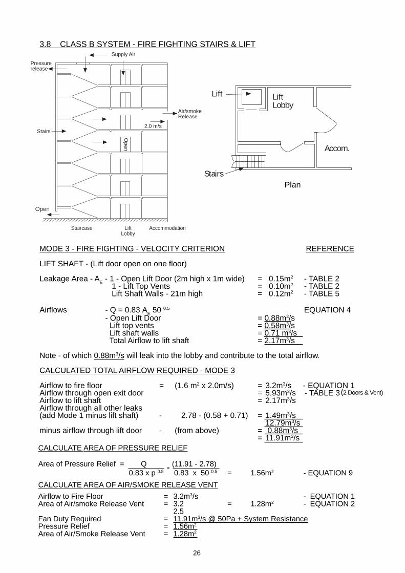
3.8 CLASS B SYSTEM - FIRE FIGHTING STAIRS & LIFT
MODE 3 - FIRE FIGHTING - VELOCITY CRITERION REFERENCE
LIFT SHAFT - (Lift door open on one floor)
Leakage Area - AE - 1 - Open Lift Door (2m high x 1m wide) = 0.15m2 - TABLE 2 1 - Lift Top Vents = 0.10m2 - TABLE 2 Lift Shaft Walls - 21m high = 0.12m2 - TABLE 5
Airflows - Q = 0.83 AE 50 0.5 EQUATION 4- Open Lift Door = 0.88m3/s Lift top vents = 0.58m3/s Lift shaft walls = 0.71 m3/s Total Airflow to lift shaft = 2.17m3/s
Note - of which 0.88m3/s will leak into the lobby and contribute to the total airflow.
CALCULATED TOTAL AIRFLOW REQUIRED - MODE 3
Airflow to fire floor = (1.6 m2 x 2.0m/s) = 3.2m3/s - EQUATION 1Airflow through open exit door = 5.93m3/s - TABLE 3Airflow to lift shaft = 2.17m3/sAirflow through all other leaks(add Mode 1 minus lift shaft) - 2.78 - (0.58 + 0.71) = 1.49m3/s
12.79m3/sminus airflow through lift door - (from above) = 0.88m3/s
= 11.91m3/sCALCULATE AREA OF PRESSURE RELIEF
Area of Pressure Relief = Q (11.91 - 2.78) 0.83 x p 0.5 0.83 x 50 0.5 = 1.56m2 - EQUATION 9
CALCULATE AREA OF AIR/SMOKE RELEASE VENT
Airflow to Fire Floor = 3.2m3/s - EQUATION 1Area of Air/smoke Release Vent = 3.2 = 1.28m2 - EQUATION 2
2.5Fan Duty Required = 11.91m3/s @ 50Pa + System ResistancePressure Relief = 1.56m2
Area of Air/Smoke Release Vent = 1.28m2
Staircase LiftLobby
Accommodation
Supply Air
Pressurerelease
2.0 m/sStairs
Open
Air/smokeRelease
Open
LiftLobby
Accom.
Stairs
Lift
Plan
(2 Doors & Vent)
=
27
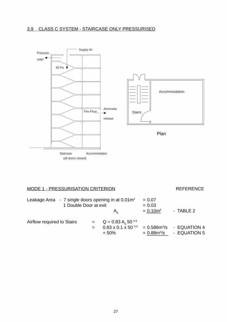
3.9 CLASS C SYSTEM - STAIRCASE ONLY PRESSURISED
Plan
MODE 1 - PRESSURISATION CRITERION REFERENCE
Leakage Area - 7 single doors opening in at 0.01m2 = 0.07 1 Double Door at exit = 0.03
AE = 0.10m2 - TABLE 2
Airflow required to Stairs = Q = 0.83 AE 50 0.5
= 0.83 x 0.1 x 50 0.5 = 0.586m3/s - EQUATION 4+ 50% = 0.88m3/s - EQUATION 5
Accommodation
Stairs
Staircase Accommodation
50 Pa
(all doors closed)
Fire FloorAir/smoke
release
Supply AirPressure
relief
28
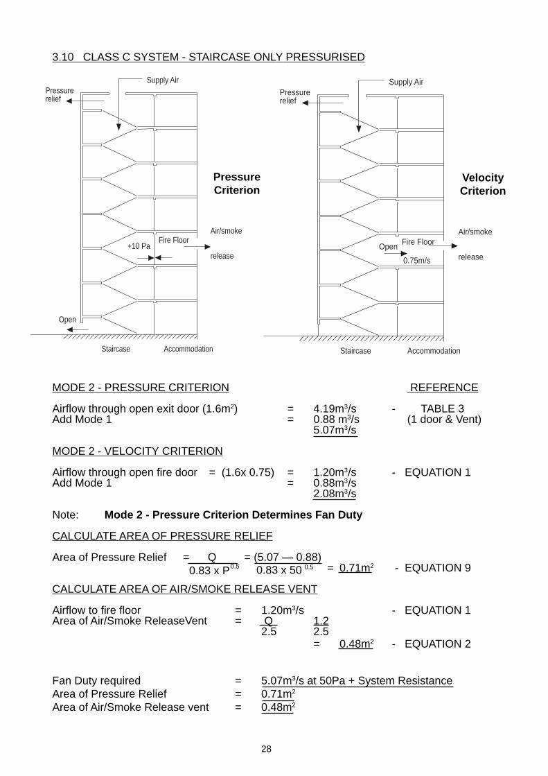
3.10 CLASS C SYSTEM - STAIRCASE ONLY PRESSURISED
MODE 2 - PRESSURE CRITERION REFERENCE
Airflow through open exit door (1.6m2) = 4.19m3/s - TABLE 3Add Mode 1 = 0.88 m3/s (1 door & Vent)
5.07m3/s
MODE 2 - VELOCITY CRITERION
Airflow through open fire door = (1.6x 0.75) = 1.20m3/s - EQUATION 1Add Mode 1 = 0.88m3/s
2.08m3/s
Note: Mode 2 - Pressure Criterion Determines Fan Duty
CALCULATE AREA OF PRESSURE RELIEF
Area of Pressure Relief = Q = (5.07 — 0.88) = 0.71m2 - EQUATION 9
CALCULATE AREA OF AIR/SMOKE RELEASE VENT
Airflow to fire floor = 1.20m3/s - EQUATION 1Area of Air/Smoke ReleaseVent = Q 1.2
2.5 2.5= 0.48m2 - EQUATION 2
Fan Duty required = 5.07m3/s at 50Pa + System ResistanceArea of Pressure Relief = 0.71m2
Area of Air/Smoke Release vent = 0.48m2
0.83 x 50 0.50.83 x P0.5
Staircase Accommodation
Fire FloorAir/smoke
release
Supply AirPressurerelief
Open
0.75m/s
VelocityCriterion
Staircase Accommodation
Fire Floor
Supply AirPressurerelief
Open
+10 Pa
Air/smoke
release
PressureCriterion

29
CLASS D SYSTEMS - STAIRCASE ONLY PRESSURISED
MODE 1 - ALL DOORS CLOSED REFERENCE
Leakage Area = 7 single doors to accommodation at 0.01m2 = 0.07m2
1 Double Door at Exit = 0.03m2
AE = 0.10m2 - TABLE 2
Airflow required to stairs = Q = 0.83 AE 50 0.5
= 0.83 x 0.1 x 50 0.5 = 0.586m3/s - EQUATION 4+ 50% = 0.880m3/s - EQUATION 5
Accommodation
Stairs
Staircase Accommodation
50 Pa
(all doors closed)
Fire FloorAir/smoke
release
Supply AirPressure
relief
Plan
30
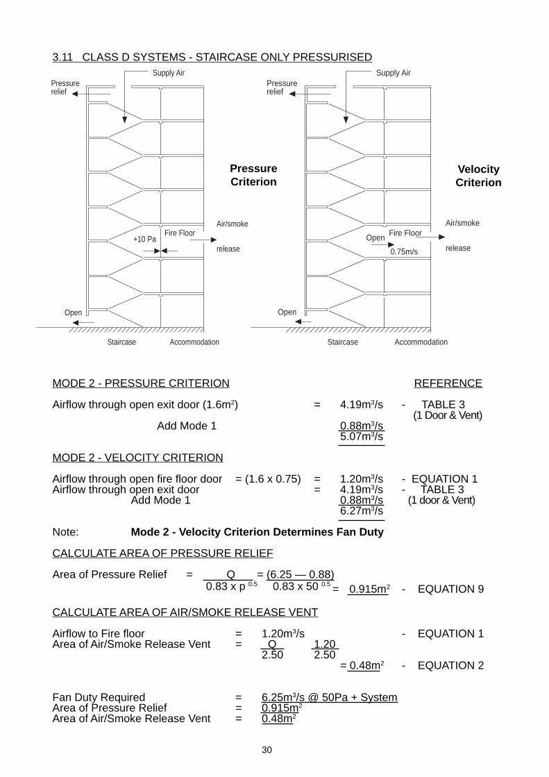
3.11 CLASS D SYSTEMS - STAIRCASE ONLY PRESSURISED
MODE 2 - PRESSURE CRITERION REFERENCE
Airflow through open exit door (1.6m2) = 4.19m3/s - TABLE 3 (1 Door & Vent)
Add Mode 1 0.88m3/s5.07m3/s
MODE 2 - VELOCITY CRITERION
Airflow through open fire floor door = (1.6 x 0.75) = 1.20m3/s - EQUATION 1Airflow through open exit door = 4.19m3/s - TABLE 3
Add Mode 1 0.88m3/s (1 door & Vent)6.27m3/s
Note: Mode 2 - Velocity Criterion Determines Fan Duty
CALCULATE AREA OF PRESSURE RELIEF
Area of Pressure Relief = Q = (6.25 — 0.88) = 0.915m2 - EQUATION 9
CALCULATE AREA OF AIR/SMOKE RELEASE VENT
Airflow to Fire floor = 1.20m3/s - EQUATION 1Area of Air/Smoke Release Vent = Q 1.20
2.50 2.50= 0.48m2 - EQUATION 2
Fan Duty Required = 6.25m3/s @ 50Pa + SystemArea of Pressure Relief = 0.915m2
Area of Air/Smoke Release Vent = 0.48m2
Staircase Accommodation
Fire FloorAir/smoke
release
Supply AirPressurerelief
Open
0.75m/s
Open
Staircase Accommodation
Fire Floor
Supply AirPressurerelief
Open
+10 Pa
Air/smoke
release
0.83 x p 0.5 0.83 x 50 0.5
VelocityCriterion
PressureCriterion
31
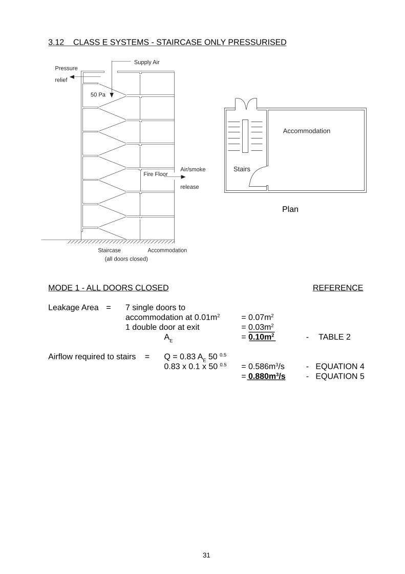
3.12 CLASS E SYSTEMS - STAIRCASE ONLY PRESSURISED
Plan
MODE 1 - ALL DOORS CLOSED REFERENCE
Leakage Area = 7 single doors toaccommodation at 0.01m2 = 0.07m2
1 double door at exit = 0.03m2
AE = 0.10m2 - TABLE 2
Airflow required to stairs = Q = 0.83 AE 50 0.5
0.83 x 0.1 x 50 0.5 = 0.586m3/s - EQUATION 4= 0.880m3/s - EQUATION 5
Staircase Accommodation
50 Pa
(all doors closed)
Fire FloorAir/smoke
release
Supply AirPressure
relief
Accommodation
Stairs

32
3.13 CLASS E SYSTEMS - STAIRCASE ONLY PRESSURISED
MODE 2 - PRESSURE CRITERION REFERENCEAirflow through open exit door (1.6m2) = 4.19m3/s - TABLE 3
(1 door & Vent)Airflow through two open accommodation doorsassuming open accommodation area at 900m2 = 0.574m3/s - TABLE 4
0.574m3/s - TABLE 4Add Mode 1 0.88m3/s
6.218m3/s
MODE 2 - VELOCITY CRITERION
Airflow through open fire floor door = 1.6 x 0.75 = 1.20m3/s - EQUATION 1Airflow through open exit door 1.6m2 = 4.19m3/s - TABLE 3
(1 door & Vent)Airflow through open accommodation door 900m2 0.574m3/s - TABLE 4
Add Mode 1 0.88m3/s6.824m3/s
Note: Mode 2 = Velocity Criterion Determines Fan Duty
CALCULATE AREA OF PRESSURE RELIEF
Area of Pressure Relief = Q (6.82 - 0.88)= 1.01m2
CALCULATE AREA OF AIR/SMOKE RELIEF VENT
Airflow to Fire Floor = 1.20m3/s - EQUATION 1Area of Air/Smoke Relief Vent = Q 1.20
2.50 2.50 = 0.48m2 - EQUATION 2
Fan Duty Required = 6.824m3/s @ 50Pa + SystemArea of Pressure Relief = 1.01m2
Area of Relief Vent = 0.48m2
Staircase Accommodation
Fire Floor
Supply AirPressurerelief
Open0.75m/s
Open
Open
Air/smoke
Release
0.83 x p 0.5 0.83 X 50 0.5
VelocityCriterion
PressureCriterion
Staircase Accommodation
Supply AirPressurerelief
Open
10 Pa +Fire door
Open
Open
Air/smoke
Release

33
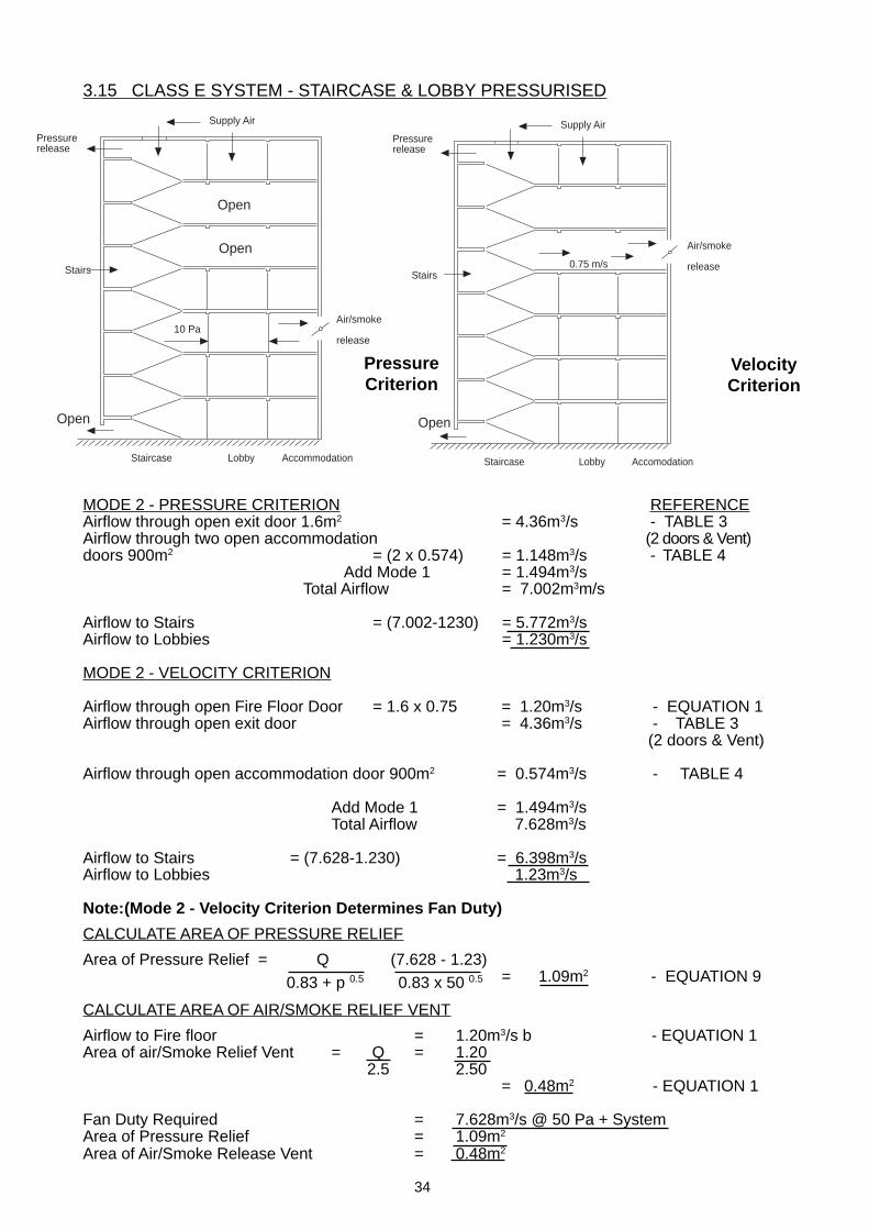
3.14 CLASS E SYSTEM - STAIRCASE & LOBBY PRESSURISED
MODE 1 - ALL DOORS CLOSED REFERENCE
Stairs
There will be no flow through Stairs/Lobby Doors
Leakage Area =1 x Double Door at exit AE= 0.03m2 - TABLE 2Airflow required to (Stairs) = Q = 0.83 A
E 0.5
= 0.83 (0.03) x 50 0.5 = 0.176m3/s - EQUATION 4 + 50% 0.264m3/s - EQUATION 5
Lobbies
Leakage Area = 7 x Single doors opening outat 0.02 = 0.14m2 - TABLE 2
Airflow required to (Lobbies) = Q = 0.83 AE 50 0.5
= 0.83 (0.03) x 50 0.5 = 0.82m3/s - EQUATION 4+ 50% = 1.23m3/s - EQUATION 5
Total Airflow Required Mode 1 = 1.23 + 0.264 =1.494m3/s
Staircase Lobby Accommodation
Supply Air
Pressurerelease
Stairs
Fire Door50 PaFireFloor
Air/smoke
Release
Plan
Lobby
Accom.
Stairs
34
3.15 CLASS E SYSTEM - STAIRCASE & LOBBY PRESSURISED
MODE 2 - PRESSURE CRITERION REFERENCEAirflow through open exit door 1.6m2 = 4.36m3/s - TABLE 3Airflow through two open accommodation (2 doors & Vent)doors 900m2 = (2 x 0.574) = 1.148m3/s - TABLE 4
Add Mode 1 = 1.494m3/s Total Airflow = 7.002m3m/s
Airflow to Stairs = (7.002-1230) = 5.772m3/sAirflow to Lobbies = 1.230m3/s
MODE 2 - VELOCITY CRITERION
Airflow through open Fire Floor Door = 1.6 x 0.75 = 1.20m3/s - EQUATION 1Airflow through open exit door = 4.36m3/s - TABLE 3
(2 doors & Vent)
Airflow through open accommodation door 900m2 = 0.574m3/s - TABLE 4
Add Mode 1 = 1.494m3/sTotal Airflow 7.628m3/s
Airflow to Stairs = (7.628-1.230) = 6.398m3/sAirflow to Lobbies 1.23m3/s
Note:(Mode 2 - Velocity Criterion Determines Fan Duty)
CALCULATE AREA OF PRESSURE RELIEF
Area of Pressure Relief = Q (7.628 - 1.23) = 1.09m2 - EQUATION 9
CALCULATE AREA OF AIR/SMOKE RELIEF VENT
Airflow to Fire floor = 1.20m3/s b - EQUATION 1Area of air/Smoke Relief Vent = Q = 1.20
2.5 2.50 = 0.48m2 - EQUATION 1
Fan Duty Required = 7.628m3/s @ 50 Pa + SystemArea of Pressure Relief = 1.09m2
Area of Air/Smoke Release Vent = 0.48m2
Staircase Lobby Accommodation
Supply Air
Pressurerelease
Stairs
10 PaAir/smoke
release
Open
Open
Open
Staircase Lobby Accomodation
Supply AirPressurerelease
Stairs0.75 m/s
Air/smoke
release
Open
VelocityCriterion
PressureCriterion
0.83 + p 0.5 0.83 x 50 0.5

35
4. FAN SELECTION
The fan performance and dimensional data is included with this paper to enable design-ers to quickly size a suitable supply fan for a particular system.
The Performance Curves are taken from Woods JM Aerofoil Fan Data and are pre-sented as “Block Curves” covering the performance range of a particular fan on a TotalPressure/Volume Flow Scale.
The example outlined on the curves and tables are the Class B System - Fire-fightingStair & Lifts
Fan Duty Required = 11.91m3/sec at 300Pa (Total Pressure)Fan Selected = 90JM/25/4/6/.....Motor Rating = 9.0kW @ 32° PAPhysical Size (max.) = 1006mm dia. x 520mm longWeight = 183 kg
This may not be the only, or indeed, the best selection for this particular duty, but will atleast allow design work to proceed whilst the selection is being refined by Woods Engi-neers.
In addition, all fans both supply and extract, for pressurisation system, are now requiredto be provided with 100% Standby. Mounting the two fans in series will create addi-tional resistance on the running fan and the fan duty will need modifying to allow for this.Again, Wood’s Engineers should be consulted.
Woods Air Movement Engineers are trained in the application of the fans for Pressurisa-tion System and are able to provide advice and support during the design and fan selec-tion stages.
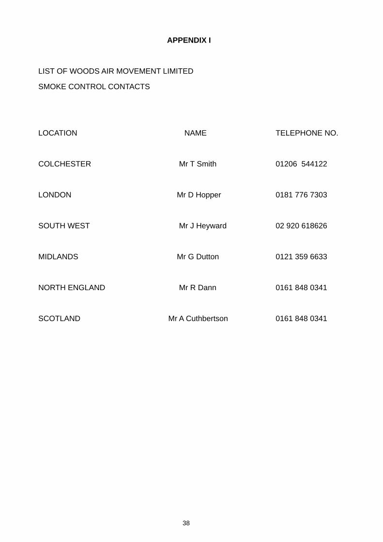
A list of name contacts is detailed on Appendix 1.
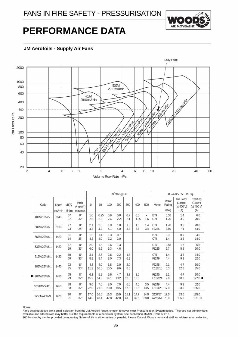
36
NotesFans detailed above are a small selection from the JM Aerofoil range, chosen to cover most Pressurisation System duties. They are not the only fansavailable and alternatives may better suit the requirements of a particular system, see publication JM/SS, C23a or C1a.100 % standby can be provided by mounting JM Aerofoils in either series or parallel. Please Consult Woods technical staff for advise on fan selection.
PERFORMANCE DATA
JM Aerofoils - Supply Air Fans
FANS IN FIRE SAFETY - PRESSURISATION
40JM2840 rev/min
56JM
- 14
20 re
v/min
50JM2910 rev/min
63JM
- 14
20 re
v/min
71JM
- 14
20 re
v/min
80JM
- 14
40 re
v/min
90JM
- 14
50 re
v/min
100J
M - 14
50 re
v/min
125J
M - 14
70 re
v/min
Duty Point
300
2000
1000800
600
400
200
10080
60
40
20
Tota
l Pre
ssur
e Pa
.2 .4 .6 .8 1 2 4 6 8 10 20 40
Volume Flow Rate m3/s
60
m3/sec @ Pa 380-420 V / 50 Hz / 3φ
Code Speed
rev/min
dB(A)
@ 3m
PitchAngle (°)min/max
0 50 100 200 300 400 500 MotorMotorRating
(kW)
Full LoadCurrent
(at 400 V)(A)
StartingCurrent
(at 400 V)(A)
40JM/16/2/5... 2840 8°32°
0.952.5
0.92.4
0.82.25
0.72.1
0.51.85
-1.6
BT9CT9
0.581.70
1.43.5
6.020.0
50JM/20/2/6... 2910 8°24°
2.04.2
1.94.1
1.84.0
1.63.8
1.53.6
1.43.4
CT9F2225
1.703.80
3.57.1
20.044.0
56JM/20/4/6... 1420 8°38°
1.44.0
1.33.2
0.73.0
BT9CT9
0.31.4
0.93.5
4.614.0
63JM/20/4/6... 1420 8°36°
1.85.6
1.65.3
1.34.6
CT5F2225
0.582.7
1.75.8
6.530.0
71JM/20/4/6... 1420 8°36°
2.88.4
2.68.0
2.27.3
1.66.3
CT9F2249
1.44.4
3.59.3
14.052.0
80JM/25/4/6... 1440 8°36°
4.010.8
3.810.5
3.09.6
2.08.0
F2245D132/18
2.16.3
4.712.8
30.085.0
90JM/25/4/6... 1450 8°32°
5.914.6
5.614.1
4.713.2
3.812.0
2.510.5
F2245D132/24
2.19.0
4.718.3
30.0127.0
1.02.6
2.14.3
1.54.2
2.06.0
3.18.8
4.211.2
6.215.2
6767
7773
6164
6769
6969
7275
7579
100JM/25/4/6... 1450 8°32°
7.021.0
8.020.0
7.018.5
6.017.5
4.515.5
3.513.5
F2249D160/26
4.417.0
9.333.0
52.0185.0
9.022.0
7883
125JM/40/4/9... 1470 8°32°
16.643.4
16.342.8
15.942.0
15.141.0
14.739.5
14.038.0
D200/57W225/MF
17.073.0
33.0135.0
185.01010.0
17.044.0
9091
37
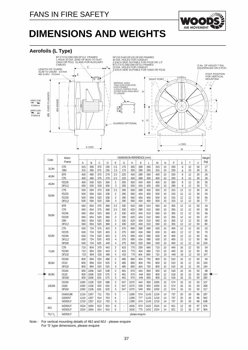
Aerofoils (L Type)
Note : For vertical mounting details of 48J and 60J - please enquireFor 'S' type dimensions, please enquire
DIMENSIONS AND WEIGHTS
FANS IN FIRE SAFETY
C
ØB
OV
ER
FLA
NG
ES
ØA
INS
IDE
E
GUARDS OPTIONAL
AIRFLOW
FORM B
AIRFLOW
FORM A
K CRS
DF132,D160,DF132,DF160 FRAMES40 DIA. HOLES FOR CONDUIT.2 EACH SIDE SUITABLE FOR PG29 OR 1.5"BT,CT,F22,D80,D90,DF112 FRAMES23 DIA. HOLES FOR CONDUIT.2 EACH SIDE SUITABLE FOR CM20 OR PG16
S No. OF HOLES T DIA.EQUISPACED ON H PCD.
L CRS
M
SIGHT PORT
DP
BT,CT,F22,D80,D90,DF112 FRAMES1 HOLE 20 DIA. (END OF BOX) TO SUITCM16 OR PG11 GLAND FOR AUXILIARYCABLES
G
FOOT POSITIONFOR VERTICALMOUNTING
VLENGTH OF GUARD31JM TO 100JM - 137mm48J & 60J - 212mm
IMPERIAL SIZEST/Box D160,D180,D200,D225 FRAMES2-HOLES TAPPED PG29OTHER SIZES AVAILABLETO ORDER
CodeMotorFrame
DIMENSION REFERENCE (mm) Weight(kg)A B C D E G H K L M N P S T
31JM8
40JMBT9CT5
400400
480480
375375
279279
2.52.5
225225
450450
289289
350350
400400
1010
250250
88
1212
45JM F2229 450 530 520 306 3 255 500 434 400 450 10 280 8 12
71JM
263055
303030
V
80JM
90JM
100JM
CT5 315 395 375 235 2.5 175 355 289 265 315 10 200 108 2730
50JM
CT9F2225F2229
500500500
594594594
375520520
338338338
2.533
290290290
560560560
289434434
450450450
500500500
101010
315315315
121212
121212
345465
303030
56JM
BT9CT9F2245F2229
560560560560
654654654654
375375520520
368368368368
2.52.533
330330330330
620620620620
289289434434
510510510510
560560560560
10101010
355355355355
12121212
12121212
34385667
50505050
63JM
CT5F2225F2249
630630630
724724724
375520520
403403403
333
375375375
690690690
289434434
580580580
630630630
101010
400400400
121212
121212
527081
505050
CT9 710 804 375 443 3 415 770 259 660 710 10 440 16 12 5450F2249 710 804 520 443 3 415 770 404 660 710 10 440 16 12 8550
710 804 415 770 660 710 10 440 16 12 50404480 147DF132 520 4
F2249D132
800800
894894
520520
488525
35
485485
860860
404404
750750
800800
1010
510510
1616
1212
94163
5050
800 894 485 860 750 800 10 510 16 12 50404525 194DF132 520 5F2245 900 1006 520 538 3 491 970 444 850 900 10 518 16 15 8850D132 900 1006 520 575 5 491 970 444 850 900 12 518 16 15 18350
900 1006 491 970 549 850 900 12 518 16 15 50575 280DF160 625 5
F2249 1000 1106 520 588 3 547 1070 444 950 1000 10 574 16 15 10750D160 1000 1106 625 625 5 547 1070 539 950 1000 12 574 16 15 26850
1000 1106 547 1070 549 950 1000 12 574 16 15 50625 317DF160 625 5
D160/LBK 1219 1357 711 753 5 - 1289 574 1143 1219 14 737 20 18 28786D200/57 1219 1357 914 753 6 - 1289 777 1143 1219 14 737 20 18 56286
1219 1357 - 1289 674 1143 1219 14 737 20 18 86753 638W200/LF 813 648J
W200/LF 1524 1694 813 910 6 - 1626 674 1422 1524 14 921 12 18 67687W200/LF 1524 1694 914 910 6 - 1626 775 1422 1524 14 921 12 18 90487
W200/LF
60J
75J 1/2 please enquire
315 395 175 355 289 265 315 10 200 10 30235 31D80 375 2.5
450 530 255 500 434 400 450 10 280 8 12 30306 72DF112 520 3
500 594 290 560 434 450 500 10 315 12 12 30338 77DF112 520 4
560560
654654
330330
620620
434434
510510
560560
1010
355355
1212
1212
5050
368368
5880
D90DF112
520520
34
630630
724724
375375
690690 529
580580
630630
1010
400400
1212
1212
5050
434403440
96234DF160
DF112 520625
44
38
APPENDIX I
LIST OF WOODS AIR MOVEMENT LIMITED
SMOKE CONTROL CONTACTS
LOCATION NAME TELEPHONE NO.
COLCHESTER Mr T Smith 01206 544122
LONDON Mr D Hopper 0181 776 7303
SOUTH WEST Mr J Heyward 02 920 618626
MIDLANDS Mr G Dutton 0121 359 6633
NORTH ENGLAND Mr R Dann 0161 848 0341
SCOTLAND Mr A Cuthbertson 0161 848 0341

39

40
Ref: WTP 42
Related Documents