1655 (240) I ·1517 (220) 1379 (200) 1241 (180) ' 1103 (160) 965 (140) 827 i (120) ' - 690 (100) 552 (80) 414 (60) 276 (40) 138 (20) 0 I I I I Tensile strength -y / v / v / v / / I Tensile / Tensiie v v I / / v v ./ / ...- I I v / "" "' / I / / / v / 71 ,, '-Yield strength I y (0.2 % offset)- l I I / "-< Elongation "" I '-Yield strength - I (0.2% offset) "' I ..--- Elongation v I I' "--Yield strength :z (0.2% offset) I I I I ."""' ' " ........... 1o---- Elongation (a) ............. ........... (b) - -- - ...... (c) -- 0 10 20 30 40 50 60 0 10 20 30 40 50 60 0 10 20 30 40 50 60 Cold work , 0 /o Cold work,% Cold work, % 80 60 0 - c 40 .2 0 0' c 20 .2 w 0 igure 1-1. Effecz of cold working on I ensile properzies ofzhree auszenizic szainless szeels. (a) zype 301, (b) zype 302. and :) zype 304.

Stainless Steels Course Transparencies
Dec 01, 2015
Welcome message from author
This document is posted to help you gain knowledge. Please leave a comment to let me know what you think about it! Share it to your friends and learn new things together.
Transcript
1655 (240)
I ·1517 (220) 1379 (200) 1241 (180)
' 1103 ~ (160)
~ 965 ~ (140) ~ 827 i (120) ' - 690
(100) 552 (80) 414 (60)
276 (40)
138 (20)
0
I I I I Tensile strength -y /
v / v
/ v /
/ I Tensile strength~ / Tensiie strength~
~
v v I / / v v
./ / ~ ...-I I v / "" ~ "' /
I / /
/ v / 71 ,,
'-Yield strength I
y (0.2 % offset)-
l I I / "-< ~ Elongation
"" ~ I '-Yield strength -
I (0.2% offset)
"' I ..--- Elongation
v I I' "--Yield strength
:z (0.2% offset)
I I I I ."""' ' " ........... ~ 1o---- Elongation
(a) ............. ........... (b) --- - ...... (c) --
0 10 20 30 40 50 60 0 10 20 30 40 50 60 0 10 20 30 40 50 60
Cold work , 0/o Cold work,% Cold work, %
80
60 ~ 0
-c
40 .2 0 0' c
20 .2 w
0
igure 1-1. Effecz of cold working on I ensile properzies ofzhree auszenizic szainless szeels. (a) zype 301, (b) zype 302. and :) zype 304.
\
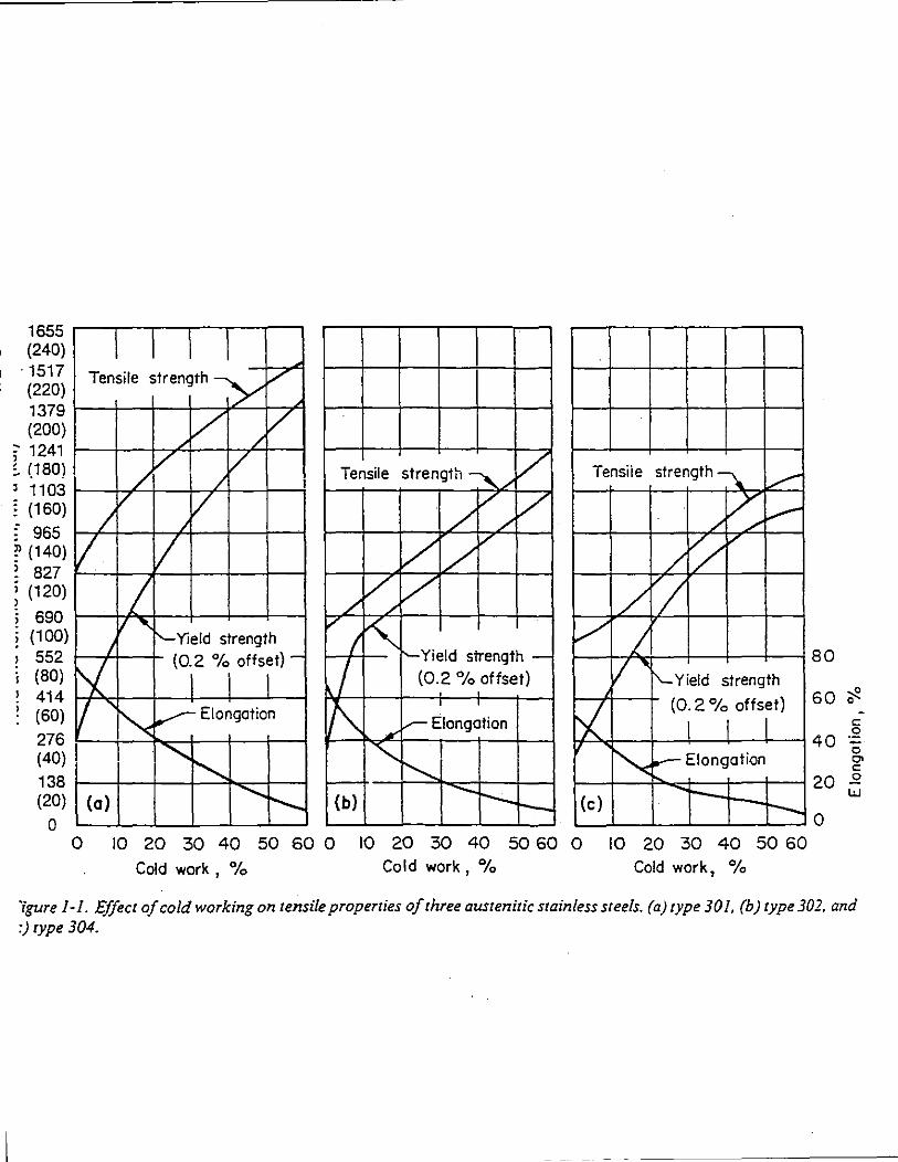
Figure 1-2. An arra_v· of machinery pares produced by machining from type 416.
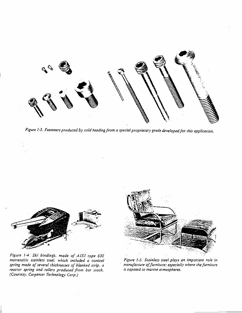
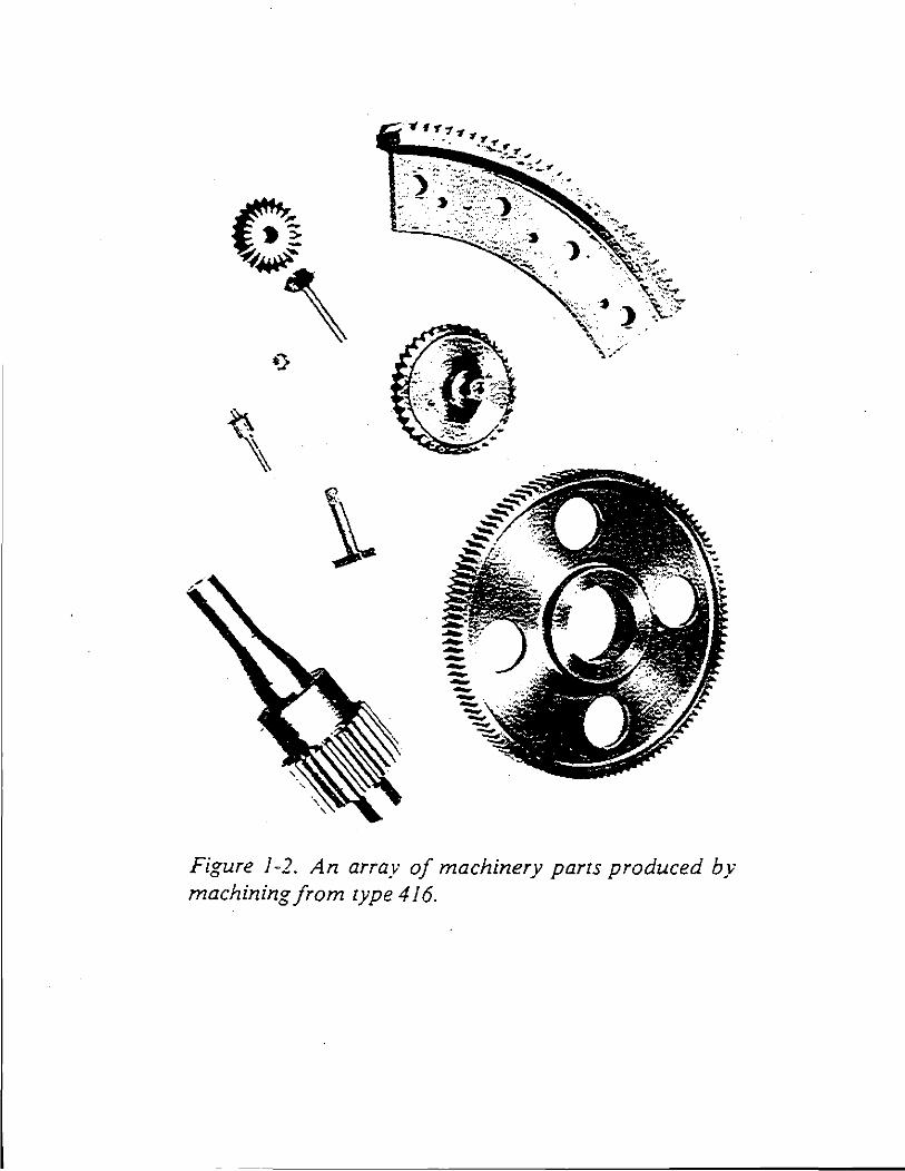
Figure 1-3. Fasteners produced by cold heading from a special proprietary grade developed for this application.
Figure I -4. Ski bindings. made of AJSJ type 630 martensitic stainless steel. which included a conical spring made of several thicknesses of blanked strip, a reactor spring and rollers produced from bar stock. (Courtesy. Carpenter Technology Corp.)
Figure 1-5. Stainless steel pla.'!S an important role in manufacture of furniture: especially where the furniture is exposed to marine atmospheres.
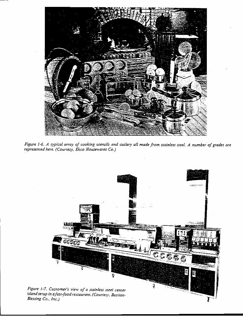
Figure 1-6. A typical array of cooking utensils and cutlery all made from stainless steel. A number of grades are represented here. (Courtesy. Ekco Housewares Co.)
Figure 1~1. Customer's view of a stainless steel center island setup in a fast-food restaurant. (Courtesv. Bastian-Blessing Co .. Inc.) · r-·
\ /
,,//"'~··
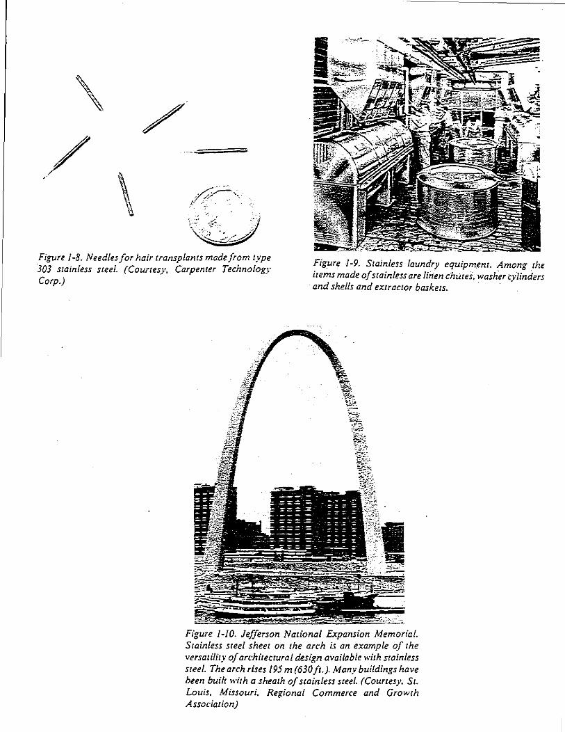
:.!~ Figure 1-8. Needles for hair transplants made from type 303 stainless steel. (Courtesy, Carpenter Technology Corp.)
Figure 1-9. Stainless laundry equipment. Among the ite,;,s made of stainless are linen chutes. washer cylinders and shells and extractor baskets. ·
Figure 1-10. Jefferson National Expansion Memorial. Stainless steel sheet on the arch i.! an example of the versatility of a"·hitectural design available with stainless steel. The arch rises 195m (630ft.). Many buildings have been built with a sheath of stainless steel. (Courtesy. St. Louis. Missouri. Regional Commerce and Growth Association)
_j
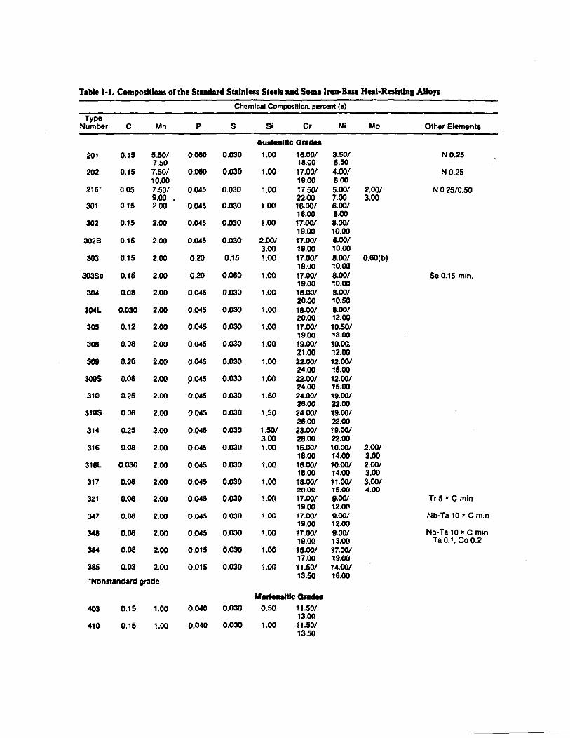
Table 1·1. Compositions of the Standard Stainless Steels and Some Iron-Base Heat·Rais11n& Alloys
Chemical Composition. pereent (a)
Type Number c Mn p s Si Cr Ni Mo Other Elements
AuahlniUc G,.dM
201 0.15 5.50/ 0.080 0.030 1.00 16.00/ 3.50/ ND.25 7.50 18.00 5.50
202 0.15 7.50/ 0.080 0.030 1.00 17.00/ 4.00/ N0.25 10.00 19.00 8.00
216' 0.05 7.50/ 0.045 0.030 1.00 17.50/ 5.00/ 2.00/ N 0.25/0.50 9.00 22.00 7.00 3.00
301 0.15 2.00 0.045 0.030 1.00 16.00/ 6.00/ 18.00 8.00
302 0.15 2.00 0.045 0.030 1.00 17.00/ 8.00/ 19.00 10.00
3028 0.15 2.00 0.045 0.030 2.00/ 17.00/ 8.00/ 3.00 19.00 10.00
303 0.15 2.00 0.20 0.15 1.00 17.00{ 8.00/ 0.60(b) 19.00 10.00
303Se 0.15 2.00 0.20 0.060 1.00 17.00/ 8.00/ Se 0.15 min. 19.00 10.00
304 0.08 2.00 0.045 0.030 1.00 18.00/ 8.00/ 20.00 10.50
304L 0.030 2.00 0.045 0.030 1.00 18.00/ 8.00/ 20.00 12.00
305 0.12 2.00 0.045 0.030 1.00 17.00/ 10.50/ 19.00 13.00
308 0.08 2.00 0.045 0.030 1.00 19.00/ 10.00. 21.00 12.00
309 0.20 2.00 0.045 0.030 1.00 22.00/ 12.00/ 24.00 15.00
309S 0.08 2.00 $).045 0.030 1.00 22.00/ 12.00/ 24.00 15.00
310 0.25 2.00 0.045 0.030 1.50 24.00/ 19.00/ 26.00 22.00
310S 0.08 2.00 0.045 0.030 1.50 24.00/ 19.00/ 26.00 22.00
314 0.25 2.00 0.045 0.030 1.50/ 23.00/ 19.00/ 3.00 26.00 22.00
316 0.08 2.00 0.045 0.030 1.00 16.00/ 10.00/ 2.00/ 18.00 14.00 3.00
316L 0.030 2.00 0.045 0.030 1.00 16.00/ 10.00/ 2.00/ 18.00 14.00 3.00
317 0.08 2.00 0.045 0.030 1.00 18.00/ 11.00/ 3.00/ 20.00 15.00 4.00
321 0.08 2.00 0.045 0.030 1.00 17.00/ 9.00/ TI5•Cmin 19.00 12.00
347 0.08 2.00 0.045 0.030 1.00 17.00/ 9.00/ Nb-Ta 10 x C min 19.00 12.00
348 0.08 2.00 0.045 0.030 1.00 17.00/ 9.00/ Nb-Ta 10 • C min 19.00 13.00 TaO. I, Co0.2
384 0.08 2.00 0.015 0.030 1.00 15.00/ 17.00/ 17.00 19.00
385 0.03 2.00 O.Q15 0.030 1.00 11.50/ 14.00/
•Nonstandard grade 13.50 16.00
Marlen8lllc c.-403 0.15 1.00 0.040 0.030 0.50 11.50/
13.00 410 0.15 1.00 0.040 0.030 1.00 11.50/
13.50
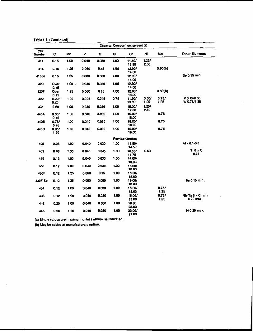
Table 1-1. (Continued)
Chemical Composition. percent (a)
Type Number c Mn p s Si Cr Nl Mo Other Elements
414 0.15 1.00 0.040 0.030 1.00 11.50/ 1.251 13.50 2.50
416 0.15 1.25 0.060 0.15 1.00 12.00/ 0.60(b) 14.00
416Se 0.15 1.25 0.080 0.060 1.00 12.001 Se 0.15 min 14.00
420 Over 1.00 • 0.040 0.030 1.00 12.001 0.15 14.00
420F Over 1.25 0.060 0.15 1.00 12.00/ 0.60(b) 0.15 14.00
422 0.20/ 1.00 0.025 0.025 0.75 11.001 0.50/ 0.75/ v 0.1510.30 0.25 13.00 1.00 1.25 W0.7511.25
431 0.20 1.00 0.040 0.030 1.00 15.00/ 1.251 17.00 2.50
440A 0.601 1.00 0.040 0.030 1.00 16.00/ 0.75 0.75 18.00
4408 0.75/ 1.00 0.040 0.030 1.00 16.00/ 0.75 0.95 18.00
440C 0.95/ 1.00 0.040 0.030 1.00 16.001 0.75 1.20 18.00
FonlllcGradft 405 0.08 1.00 0.040 0.030 1.00 11.501 AI • 0.1.0.3
14.50 409 0.08 1.00 0.045 0.045 1.00 10.501 0.50 Ti6x C
11.75 0.75 429 0.12 1.00 0.040 0.030 1.00 14.001
16.00 430 0.12 1.00 0.040 0.030 1.00 18.001
18.00 430F 0.12 1.25 0.060 0.15 1.00 16.001
18.00 430F Se 0.12 1.25 0.060 0.060 1.00 16.001 Se0.15 min.
18.00 434 0.12 1.00 0.040 0.030 1.00 16.001 0.751
18.00 1.25 436 0.12 1.00 0.040 0.030 1.00 16.00/ 0.75/ Nb-Ta 5 • C min,
18.00 1.25 0.70 max. 442 0.20 1.00 0.040 0.030 1.00 18.00.
23.00 448 0.20 1.50 0.040 0.030 1.00 23.001 N 0.25 max.
27.00
(a) Single values are maximum unless otherwise indicated.
(b) May be added at manufactun~rs option.
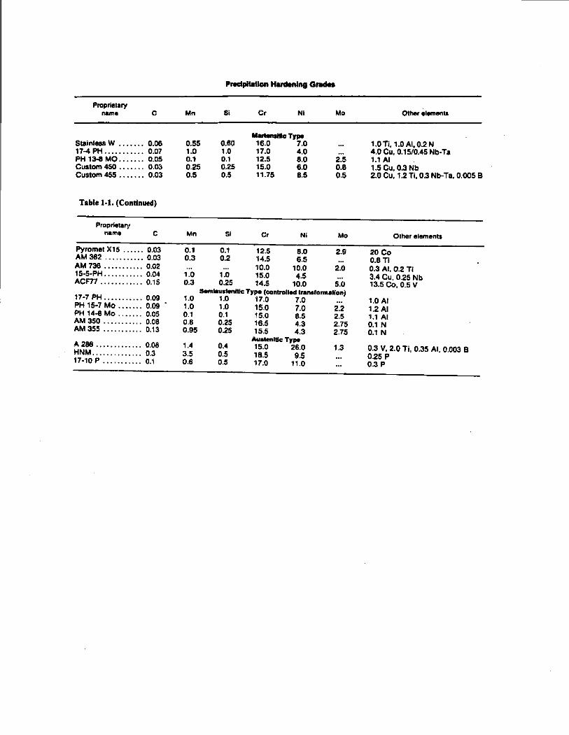
PNCipi .. Uon Honlenlng o.-
Propriolary nome c Mn Si Cr Nl Mo Other elements
M .......... cTpe Stain!us W . . . • . . . 0.06 0.55 0.60 16.0 7.0 1.0Ti. 1.0AI,0.2 N 17-4 PH ........... 0.07 1.0 1.0 17.0 4.0 4.0 Cu, 0.15/0.45 Nb-Ta PH 13-8 MO ...••.. 0.05 0.1 0.1 12.5 8.0 2.5 1.1 AI Custom 450 ...•... 0.03 0.25 0.25 15.0 6.0 0.8 1.5 Cu, 0.3 Nb Cuotom 455 . . . • • . . O.D3 0.5 0.5 11.75 8.5 0.5 2.0 Cu, 1.2 Ti, 0.3 Nb-Ta. 0.005 B
Table 1-J. (Continued)
Proprietary name c Mn Sl Cr Nl Mo Other elements
Pyromel X15 ...... 0.03 0.1 0.1 12.5 8.0 2.9 20 Co AM 362 .........•. 0.03 0.3 0.2 14.5 6.5 0.8TI AM 736 .•••.•...•. 0.02 10.0 10.0 2.0 0.3 AI, 0.2 Ti 15-5-PH . . . . . . . . . . . 0.04 1.0 1.0 15.0 4.5 3.4 Cu. 0.25 Nb ACF77 ..••....•... 0.15 0.3 0.25 14.5 10.0 5.0 13.5 Co, 0.5 V
Semiaustenltfc Type (cantrollecl transfomt~~lfon) 17-7 PH ..•..•.•.•. 0.09 1.0 1.0 17.0 7.0 1.0 AI PH 15·7 Mo .••.•.. 0.09 1.0 1.0 15.0 7.0 2.2 1.2 AI PH 14-8 Mo ..•.... 0.05 0.1 0.1 15.0 8.5 2.5 1.1 AI AM 350 ......•.... 0.08 0.8 0.25 16.5 4.3 2.75 0.1 N AM 355 .•....•.... 0.13 0.95 0.25 15.5 4.3 2.75 0.1 N
Au•~en~t~c Tr .. A 286 ..•.......... 0.08 1.4 0.4 15.0 26.0 1.3 0.3 V, 2.0 Ti. 0.35 AI. 0.003 B HNM .............. 0.3 3.5 0.5 18.5 9.5 0.25 p 17-10 p ........... 0.1 0.6 0.5 17.0 11.0 0.3 p
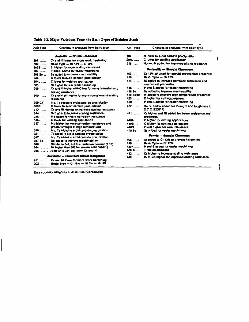
Table 1-2. Major Variations From tbelluic Types or Staialeos Steels
AJSITypo
301 ••••.• 302 ..... . 3028 ... . 303 ..... . 303 Sa ..
*······ :IOOL ••••• 305 308
309
309 CT . 3095 ...• 310 314 .... .. 316 ..... . 316L .... . 311
Changes in analyses from blsic type -----Cr and Ni lower for more wortc hardening 8atcTJP1-Cr1ft-Nin. Sl higher for more acallng resistance P ancs S added tor euier machining Se added to improve rn.Chlnabtlity C lower to avoid carbide precipitation c lower ror welding application Ni higher for Ina work hardening Cr and Ni higher with C low for more corrosion and scaling resistance Cr and Ni still higher tor mon1 corro~ion and sealing resistance Nb. Ta added to avoid carbide preciphatlon Clower to avoid carbide precipitlltion Cr and Nl higt'lest to Increase scaling resistance Si higher 10 increase scaling resistance Mo added tor more corroaion ,_latance C lower for welding application Mo higher tor more corrosion Mttance and gre.ter strength at high tempe,.tures
318 Nb;Ta added to avoid carbide precipitalion 321 Ti added to avoid carbide precipitation 341' Nb. Ta added to avoid carbide precipitation 347 S. .. Se added to improve machinability 348 ...... Similar to 347, but low tantalum content (0. 10) 384 .•..•.• Ni higher ttt.n 306 for eevere cold hucllng 385 •••.•.. Similar to 384 but lower Cr and Nl
-tllc-Ch ..... __ _
201 Cr and Nl rower for rnor. walk hardening 202 ll88lc 1)pe - Cr 18~ - Ni ~ - Mn R
Data courtesy Allegheny Ludlum SlMI Corporation
AISI Type
204 •···•· 204L ..••• 216 .....
403 410 .,. 416 416 Sa .. •1a Spec 420 •..... 420F ••...
422
431
440.0 4408 440C 440Se ..
405 •.••..
430 ······ .30F .... . ll30 n .. . 442 "6 ......
Changes In analyses from basic type
C lower to avoid carbide precipitation C rower for welding application Mo and N added for improved pttling resistance
-tie- SIJolthl a. ..... _ Cr 1~ adjusted for spec~ mechanical properties 8ulc TrJIO- Cr I~ Nl added to increan corrosion resistance and mechaniCII propertiu P and S added ror easlet machining S. added to lmprov. machinability W added to Improve high temperature properties C higher for cuning purposes P and S added ror euler machining
Mo. V. and W added for strength and. toughness to 650"C (1200"F) Cr higher and Nl added tor better resistance and properties C higher tor cutting applications C higher for cutting appUcations C still higher tor v.:ear rHistence Se addecl for euier machining F---ChroAiadded to Cr 1~ to prevent hardening Bnlc TJpo - Cr lnlo P and S added tor .....,. IMChlnlng Titanium 111blllmd Cr higher to inctnae ~eating rnlallnce Cr mUI:h higher tor Improved tc:allng retistance
1-tostoln_S_
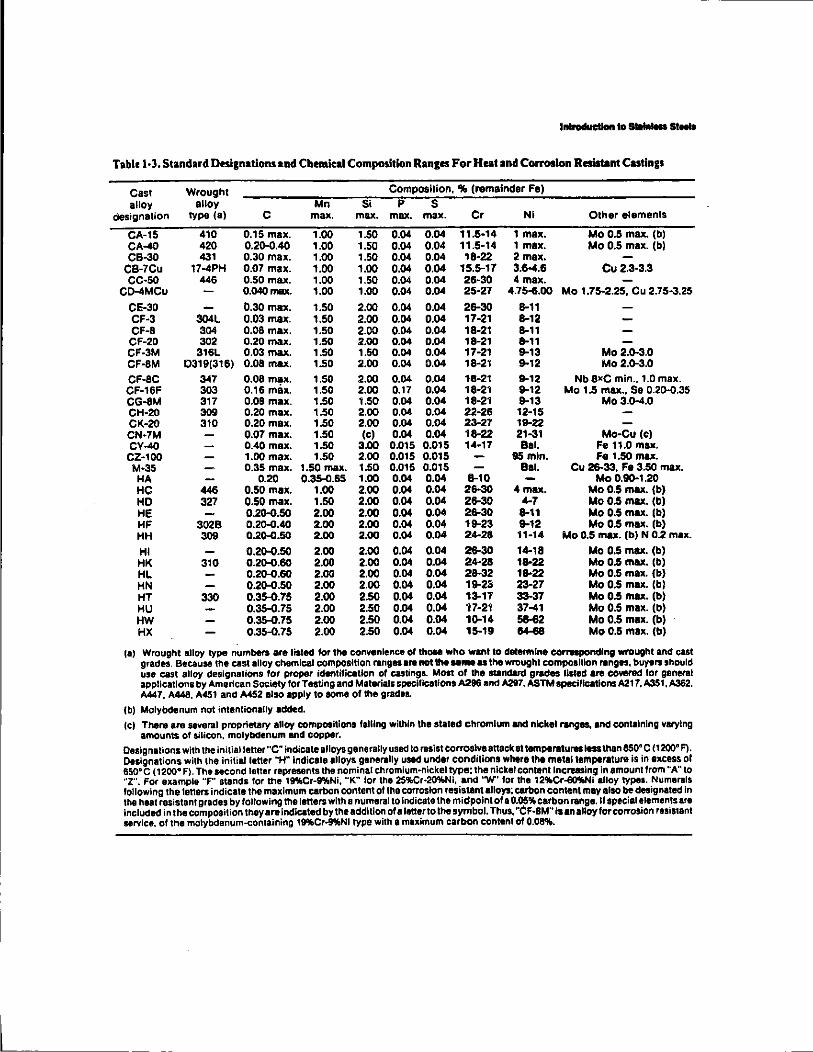
Table 1·3. Standard Desi1nations and Chemical Composition Ranges For Heat and Corooalon Resistant Castings
Cast Wrought Composition, 11M. (remainder Fe)
alloy alloy Mn Si p s designation type (8) c max. max. max. max. Cr Ni Other elements
CA-15 410 0.15 max. 1.00 1.50 0.04 0.04 11.5-14 1 max. Mo 0.5 max. (b) CA-40 420 0.20.0.40 1.00 1.50 0.04 0.04 11.5·14 1 max. Mo 0.5 max. (b) CB-30 431 0.30 max. 1.00 1.50 0.04 0.04 18·22 2max.
CB-7Cu 17-4PH 0.07 max. 1.00 1.00 0.04 0.04 15.5-17 3.6-4.6 Cu2.3·3.3 CC-50 446 0.50 max. 1.00 1.50 0.04 0.04 26·30 4 max.
CD-4MCu 0.040max. 1.00 1.00 0.04 0.04 25·27 4.75~.00 Mo 1.75-2.25, Cu 2.75-3.25
CE-30 0.30 mill<. 1.50 2.00 0.04 0.04 26-30 8-11 CF·3 304L 0.03 max. 1.50 2.00 0.04 0.04 17·21 8-12 CF-8 304 0.08 max. 1.50 2.00 0.04 0.04 18-21 8-11 CF-20 302 0.20 max. 1.50 2.00 0.04 0.04 18-21 8-11 CF-3M 316L 0.03 max. 1.50 1.50 0.04 0.04 17·21 9-13 Mo 2.0.3.0 CF·BM 0319(316) 0.08 max. 1.50 2.00 0.04 0.04 18-21 9-12 Mo 2.0.3.0
CF-BC 347 0.08 max. 1.50 2.00 0.04 0.04 18-21 9-12 Nb axe min., 1.0 max. CF·16F 303 0.16 m&x. 1.50 2.00 0.17 0.04 18-21 9-12 Mo 1.5 max., So 0.20.0.35 CG-8M 317 0.08 max. 1.50 1.50 0.04 0.04 18-21 9-13 Mo 3.D-4.0 CH-20 309 0.20 max. 1.50 2.00 0.04 0.04 22·26 12·15 CK·20 310 0.20 max. 1.50 2.00 0.04 0.04 23-27 19-22 CN·7M 0.07 max. 1.50 (c) 0.04 0.04 18-22 21-31 Mo-Cu (C) CV-40 0.40 max. 1.50 3.00 0.015 O.D15 14·17 Bal. Fe 11.0 max.
CZ·100 1.00 max. 1.50 2.00 0.015 O.D15 95mln. Fe 1.50 ma.x. M·35 0.35 max. 1.50 max. 1.50 0.015 0.015 Bal. Cu 26-33, Fe 3.50 max.
HA 0.20 0.35-{).65 1.00 0.04 0.04 8-10 Mo 0.110-1.20 HC 446 0.50 max. 1.00 2.00 0.04 0.04 26-30 4 max. Mo 0.5 max. (b) HD 327 0.50 max. 1.50 2.00 0.04 0.04 28-30 ~7 Mo 0.5 max. (b) HE 0.2().0.50 2.00 2.00 0.04 0.04 ~0 8-11 Mo 0.5 max. (b) HF 3028 0.2o-D.40 2.00 2.00 0.04 0.04 19-23 9-12 Mo 0.5 max. (b) HH 309 0.2().0.50 2.00 2.00 0.04 0.04 2~28 11·14 Mo 0.5 mu. (b) N 0.2 max.
HI 0.20.0.50 2.00 2.00 0.04 0.04 26-30 1~18 Mo 0.5 max. (bl HK 310 0.2().0.60 2.00 2.00 0.04 0.04 24-28 18-22 Mo 0.5 max. (b) HL 0.2().0.60 2.00 2.00 0.04 0.04 28-32 18-22 Mo 0.5 max. (b) HN 0.20.0.50 2.00 2.00 0.04 0.04 19-23 23-27 Mo 0.5 max. (b) HT 330 0.35-0.75 2.00 2.50 0.04 0.04 13-17 33-37 Mo 0.5 max. (b) HU 0.35-{).75 2.00 2.50 0.04 0.04 17-21 37-41 Mo 0.5 max. (b) HW 0.35-0.75 2.00 2.50 0.04 0.04 10.14 ~2 Mo 0.5 max. (b) HX 0.35-0.75 2.00 2.50 0.04 0.04 15-19 - Mo 0.5 max. (b)
(a) Wrought alloy type numbers are listed for the convenience of thOIII who want to determine corrwspondlng wrought and cut grades. Because the cast alloy chemical composition ranges are not 11M .. ,... as the wrought composition ranges, buyers should use cast alloy designations for proper identification of castings. Most of the ltlnelard grades lilted are cowrad tor general applications by American SOG.iety lor Testing and Materials specifications A296 and la97. ASTM speciflcations A217, A351, A362. A447, A448. A451 and A452 also apply to some of the grades.
(b) Molybdenum not intentionally added.
(c) There are several proprietary alloy compositions falling within the stated chromium and nickel ranges. and containing varying amounts of silicon, molybdenum and copper.
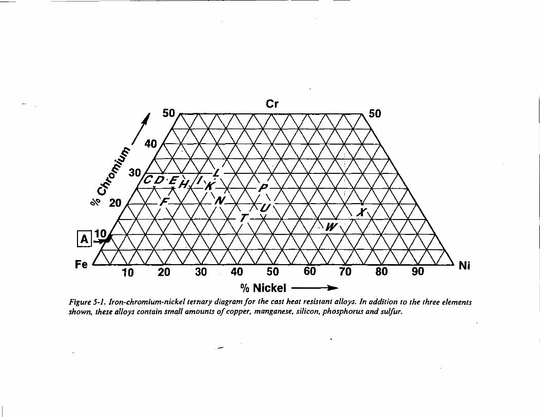
Designations with the iniUalleher "C" indicate alloys generally used to resist corroalveanackattemperaturestessthan 850° C 11200a F). Designations with the initial letter "H" Indicate alloys genet'llly uttd under conditions where the me1a1 tempel'lture is in excess or 650° C (1200• F). The second letter represents the nominal chromium-nickel type: the nickel content Increasing in amount from "A" to "Z". For example "F" stands lor the 1ftCr-9%Ni, "K" lor the 25%Cr-~Ni, and 'W' for the 12,.Cr-6t)IM,Ni alloy types. Numerals following the letters indicate the maximum carbOn content of the corrosion resistant alloys; carbon content may also be deeignattd In the heat resistant grades by ronowing the litters with a numeral to Indicate the midpoint of a 0.05~ carbon range.lf special elements are included in the composition they are indicated by the addition of alenerto the symbol. Thus, "CF-8M" is an alloy for corrosion resistant service. of the molybdenum-containing 1KCr..ftNI type with a maximum carbon content of 0.08ql,.
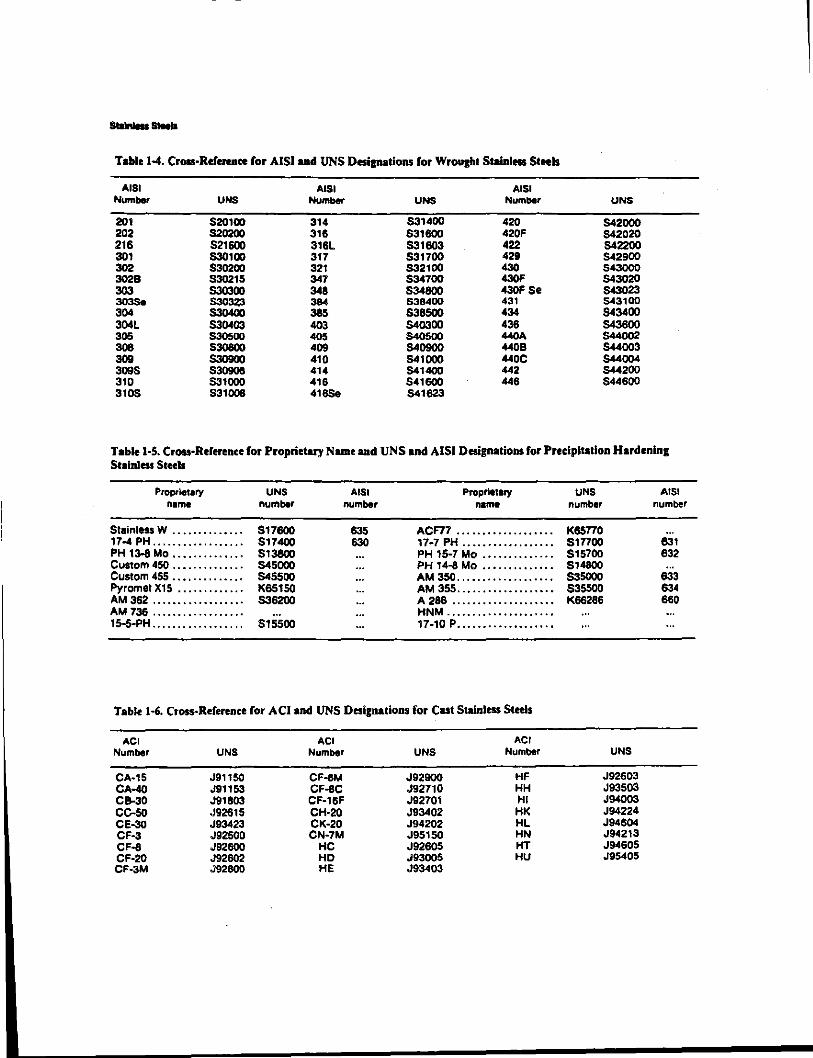
--Tallie 1-4. Cross·Refermce for AISiaad UNS Desianations for Wroucht Stainless Steels
A lSI AISI AISI Number UNS Number UNS Number UNS
201 5201110 314 $314110 420 542000 202 5202110 316 $316110 420F 542020 216 5216110 316L $31603 422 542200 301 $301110 317 531700 429 542900 302 $302110 321 S32100 430 543000 3028 S30215 347 534700 430F 543020 303 5303110 348 5346110 430F So 543023 303Se S30323 384 536400 431 543100 304 S30400 385 $365110 434 543400 304L S30403 403 540300 438 5436110 305 530500 405 5405110 440A 544002 308 530800 409 540900 4408 544003 309 S30900 410 541000 440C 544004 3095 530906 414 541400 442 544200 310 531000 416 5416110 446 544600 3105 8311106 416Se 541623
Tablel·S. Cross-Reference for Proprietary Name and UNS and AISI Designations for Precipitation Hordenine Stainless Steels
Proprie .. ry UNS A lSI Proprietary UNS A lSI name number number name number number
StalnlessW .............. 5176110 635 ACF77 . .................. Kesno . .. 17-4 PH .................. 517400 630 17·7 PH .........•..•..... 5tnoo 631 PH 13-8 Mo ..•.......•... 8138110 PH 15·7 Mo ·············· 8t5700 632 Custom 450 .............. 545000 PH 14-8 Mo .............. 814600 . .. Custom 455 ..•........... 545500 AM350 ................•.. $35000 633 Pyromet XIS ············· K65150 AM 355 ................... 835500 634 AM382 ·················· $36200 A266 ···················· K66286 660 AM736 .................. HNM ..................... 15-S.PH ............... , .. 5155110 11·10 P ...................
Table 1·6. Cross-Reference for ACiand UNS Designations for Cut Stainless Steels
ACI ACI ACI Number UNS Number UNS NIJmber UNS
CA·15 J91150 CF-8M J92900 HF J92603 CA-40 J91153 CF-8C J92710 HH J93503 C&-30 J91803 CF·16F J92701 HI J94003 CC-50 J92615 CH-20 J93402 HK J94224 CE-30 J93423 CK·20 J94202 HL J94604 CF·3 J92500 CN·7M J95150 HN J94213 CF-8 J92600 HC J92605 HT J94605 CF·20 J92602 HD J93005 HU J95405 CF-3M J92800 HE J93403
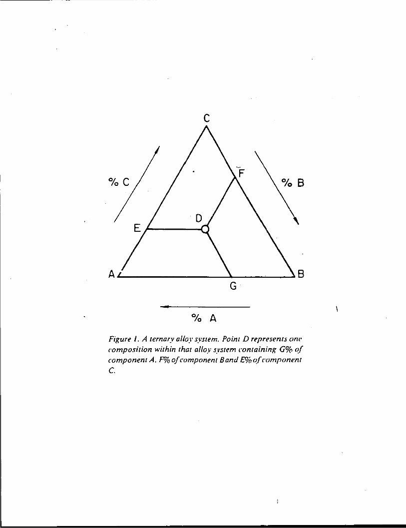
c
%C
A~------------~----~~8 G
Figure I. A ternary alloy system. Point D represents om· composition within that alloy system containing G% c~{ component A. F% of component Band £!1(, c~{ component c.
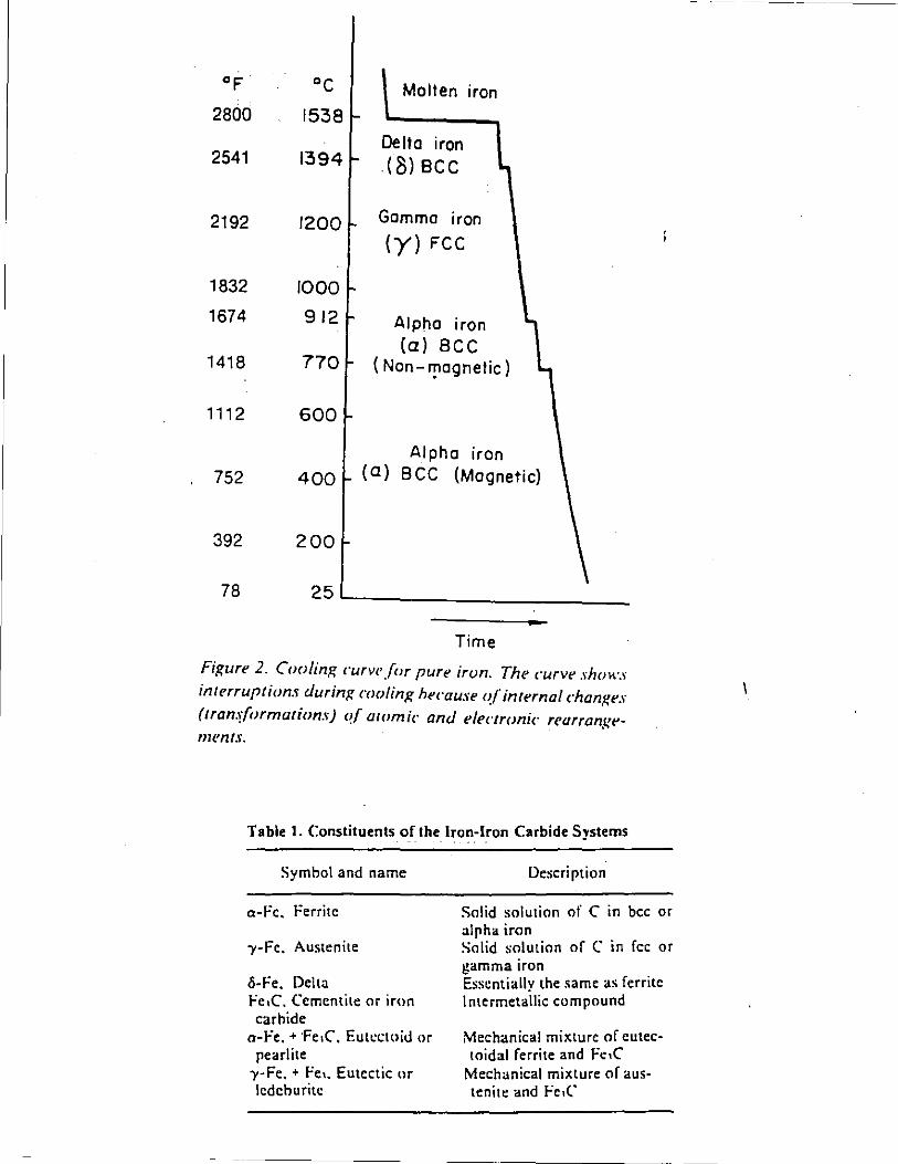
2800 1538
2541 1394
2192 1200
1832 1000
1674 912
1418 770
1112 600
Mallen iran
Delta iran (8)BCC
Gamma iron
(y) FCC
Alpha iron (a) sec
(Non- f!lagnetic)
Alpha iran 752 400 (a) B CC (Magnetic)
392 200
78 25 ..__ __________ _
Time
Figure 2. Cooling curve for pure irun. The curve shows interruptions during cooling hecause <!/"internal chanKe-' (tran.!Iormations) C!{ atomic and electronic rearrangetn('nts.
Table I. Constituents of the Iron-Iron Carbide Systems
Symbol and name
o-Fc. Ferrite
-y-Fe. Austenite
c5-Fe. Delta Fe,C, Cementite or iron carbide
o-Fe. • ·Fe,C, Eut~ctoid or pearlite
-y-Fe. • Fe •. Eutectic or lcdeburitc
Description
Solid solution of C in bee or alpha iron Solid solution of C in fcc or gamma iron Essentially the same as ferrite lntermetallic compound
Mechanical mi"ture of eutectoidal ferrite and Fc.C
Mechanical mixture of austenite and Fe,('
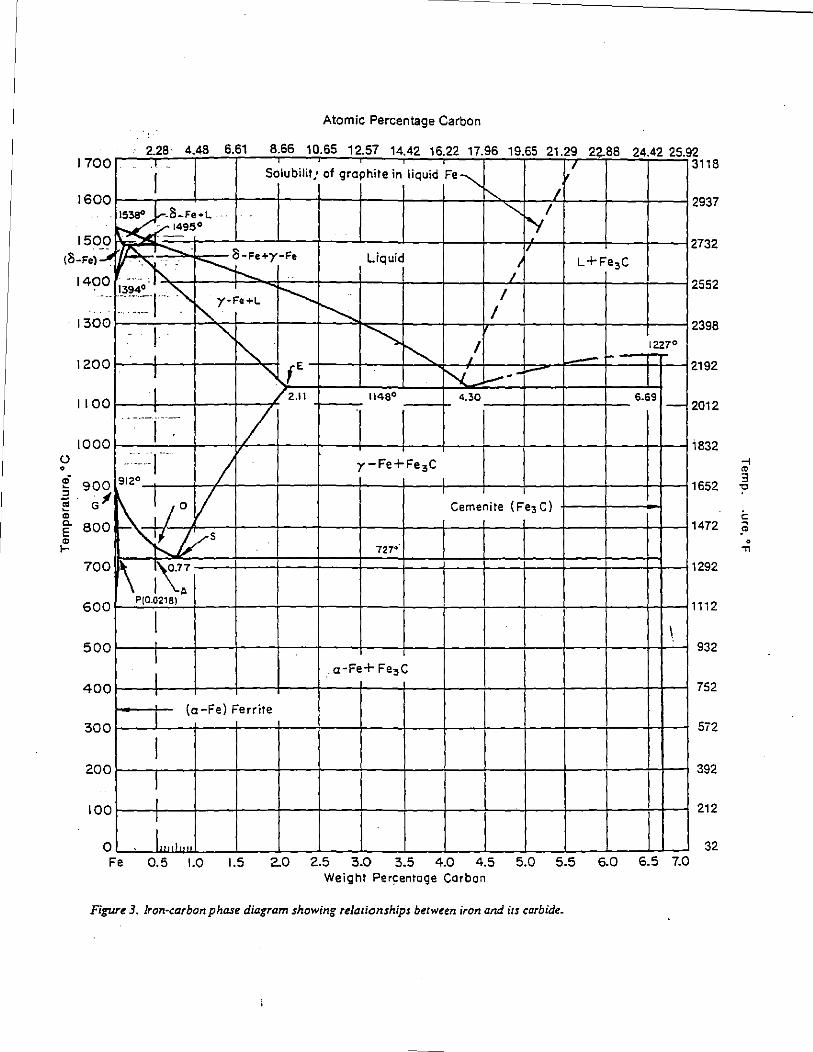
Atomic Percentage Carbon
228· 4 48 6 61 866 10 65 1257 1442 1622 1796 1965 2129 2288 2442 2592 ·'· ' , 3118 I Solubilit: of graphite in liquid Fe"""
16oor---.-~~--r---t---t---+---4---4---4"~~--~~~--~--~--~2937 8-Fe•L '-...., "v/
, ··:;- 1495 ° 1
1700
1500~~~~~-~-t--~----~--t---~---L---t---t--_,f-~~--+---+---~2732 (8-Fe}::.;.. I"': 1
......... . 8-Fe+y-Fe
1400 i394~ ~ . / Liquid
2552 ---~:=r--"-. "'-y-F• .. L I'--~ / 1
. I 300 r---_ -;-I -r>-.."'+--r----t------=~............_:--t---+-+------!-+-+----t--12398 ~ ~"'-... I 12zro
() 0
I 20 0 !----+-1 ---ii----t1__,., "-..-t E -1---h-+-l~ -.........J__,14---b...-~-==--lr::.:::::j::r-~ 2192 I '~f~~~---~~'L~~~~-~-r·-~r--r--~
1100 ----1-- //zJt +----1148° .----+-- 4.30:--,--+---1:------+--6.691- 2012
I000~--~--+---~~~---+----1----t---+---4---~--~---+--~~~i832
y-Fe+Fe 3C
-T---1-.f-t---r--t---r--4---t-:--+--~, ---+---r--+-~~1652 G
80 Cemenite {Fe3 C)
~~~4---t---1----+---~--+---r--t---4----+----rt__,1472
727°
700~~~-,~'\~0-~7:~==~==~==~===+==~==~==~==~==~==~~====~~1292
600~~·~10~.0=21~8~)-+---r---r-~--~-~--+---r--~---+----+----~~1112
I I \ 5001----t,-~-+--t--_,--+--r-~-t--_,--r_,__++__,
_l a-Fe+ Fe3C 4oor---t-,--+---4----r---+--~----t---+---+---4
1--~:---t---4-r-~
I {a-Fe) Ferrite
3oor---~~r---r---t---t---+---4---4---4---4---4----r---rt-~
200~~:~~-4--~-4'--~~--~-4--+--+--+--+~ loor-~'r-~---+---+---+---+---+---+---r--~--,_ __ ,_ __ ,_r-1
: o~~'Will'"~·,u_·--~--~--~--~--~--~--~~~~--~--~~~
2.0 2.5 3.0 3.5 4.0 4.5 5.0 5.5 6.0 6.5 7.0 Fe 0.5 1.0 1.5 Weight Per~entage Corban
Figure 3. Jron·carbonphase diagram showing relationships between iron and irs carbide.
932
752
5i2
392
212
32
-i
"' 3 "C
i:: .Cil
0 .,
AtOfl'l< ~et~loqf IWcll1111
•c IS SO
10 20 lO 40 50 60 70 eo 90
~-~~i I •• - 0.] - L
ria-~ ~ 1500
1450
1400 tl'J•' I
900 ,,z· I I I
I I ro·-~•·";' \. c- ,._ .... _ ........
.,\ '·y\
~ ,c-•·-
... L ... •j
"'I ··t ·. :!IOO:tS• •• ••
800
,,.. 700
600
..... I ' .
/ I I \ I ' ' . 'r~'
!.. ... ... ....... ••••••. 'lo..~ I 500
I .... ,_ / , 400
300 Fe 10 zo 30 40 so 60 70 80 90
Weight Percentage Nickel
'F
2700
2fm
2600
1600
l
1-400
1200
1000
BOO
700
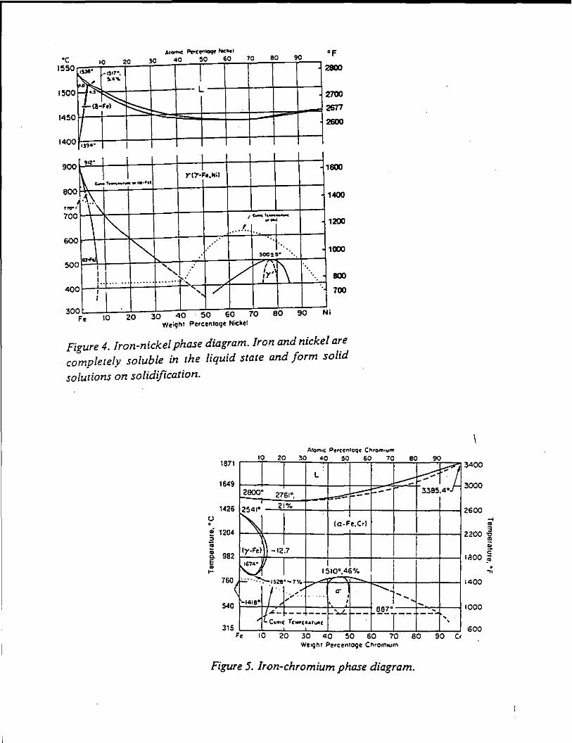
Figure 4. Iron-nickel phase diagram. /ron and nickel are completely soluble in the liquid state and form solid
solutions on solidification.
10 20 30 40 50 60 187 l
164 9
142 6 ll • ! 120 4 • ;; ;; ~ 982 ~ ...
760
540
315
<
L I zeoo· 2761°, -- --
K 21%
(a.Fe.Crl
ly-Fel -12.7 I
~I I I 1510°,46'"1.
. : .. :.:. ·>1!!28•-7•t. I
(·/ cr ['-1418° ," ..
... ' I
J~- -- --- ':.."- --" f..Cu1111: Tr...,c .. ru~tr
70 so 90
...-:: ~ -- ;385.4°
I !
' I I I I
~I l',_ ' 887° ---r- ' ' ... 10 20 30 40 so so 10 eo
Wu~l'lr Percenroge Cl"tromtum 90 Cr
Figure 5. Iron-chromium phase diagram.
3000
2600 .... ..
zzoo -5
I
I
I
~
~ c aoo _;;;
400
000
600
. ...
ATOMIC PERCENTAGE CARlON
••• ... 12.51 16.22 19.65
"' ... 10.65 , .. 42 17.98
1800 2100 ...
1500
« 2600
1•00 2SOO
~ 1300 , .
• Y<t-M3C+I. . , 2300 ~
• , •
=!ZOO • •
• • :
2100 c ~ 1100
: !900 ...
1000 r+MJC
""' ooo 1600
800 1400
• 3.0 '·' •o .. ••
WE1GH1 PERCENTAGE C,t.lt8QN
(a)
ATONIC PERCENTAGE CARBON
2.28 ••• 1500
Loquod 2600
t•oo l•lt•Loquod
t:lOO
1200
f 2100
~ 1100 . • . • 1900;;: ,
:c \000
• •
!
• 0
• 't+ICrFei 7 CJ • '
1700 ~ ..;
000 1600
1•00
tl+ICrfeltC:l
700 ,_ ' --' It• ~, ~«•ICrPo:t.C+ICtfllfltCl
1200
800 ICrFifi"C' '
o.• 0.2 0.3 o.• ~· o.o 0.7 0.0 0.9 •. o
WEIGHT PERCENT AGE CARBON
••• 1800 "' 1500
1400
IJ 1300 . • ~ uoo • . -· • ~ 1100
1000
900
ooo ,.. •• •• "
.UOMIC PEIICENT.lGE CARBON-I 66 !.Z..S7 16.22 19.U
14 41 1796
"' IOU
2800
%600
2500
2300 i ~ • • 1100 c ;;:
1900 ...
1100 .... 1400
,, zo %5 30 35 40 4, so WEIG)tT PEPCI!toll'AGE CARBON
(c) (b)
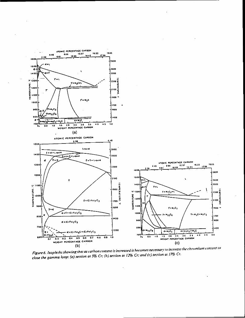
Figure 6. lsopleths sho~·ing that as rarhon nmrrnt is inarased it heC"om~s ntcts.rary w inc-rease tht! chromium conumt to
close the gamma loop: (a) section at 5% Cr: (h) stet ion at ll!';fl Cr: and (c·) serrion at 17CJf Cr.
1.3
1.2
I. I
1.0
z 0 0.9 CD a: <( 0.8 0
w ~ 0.5
0.3
0,2
8
-...PERMANENT CARBIDES AND -
-RETAINED AUSTENITE --rrr--~~•-
A+C
12
WEIGHT% CHROMIUM
F+C
SHADED ZONE COMPRISES
QUENCH-HAROENABLE ALLOYS
36
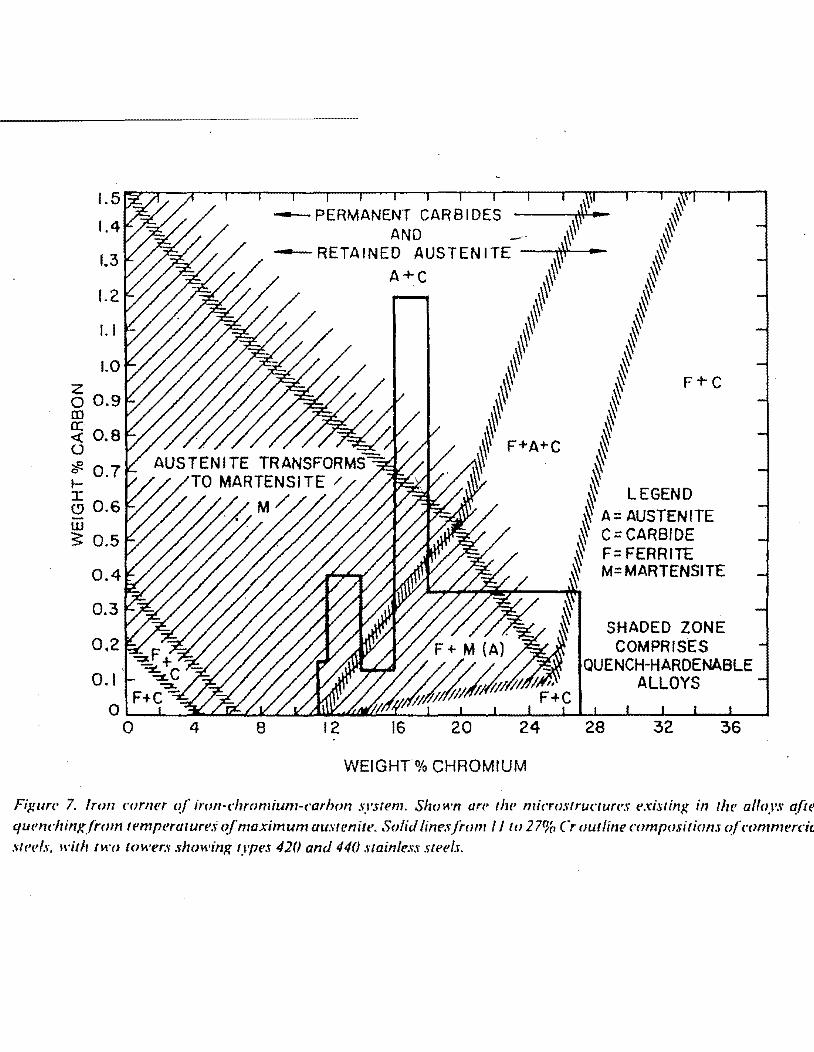
Fi}!ure 7. Iron c·orner c~f' ircm·chromium-c"arhon sprem. Shown an' the micro.wructun•s t•xisting in the• a/fays afte quendrinxfrom temperature.<; o.f'maximum au.wenite. Solid linesfrom II to 27W, Cr outline compositions c~f'<'ommercia :aeels. 1\'itlr H1·o tower:; .~lwwing types 420 and 440 stainless steel.r.
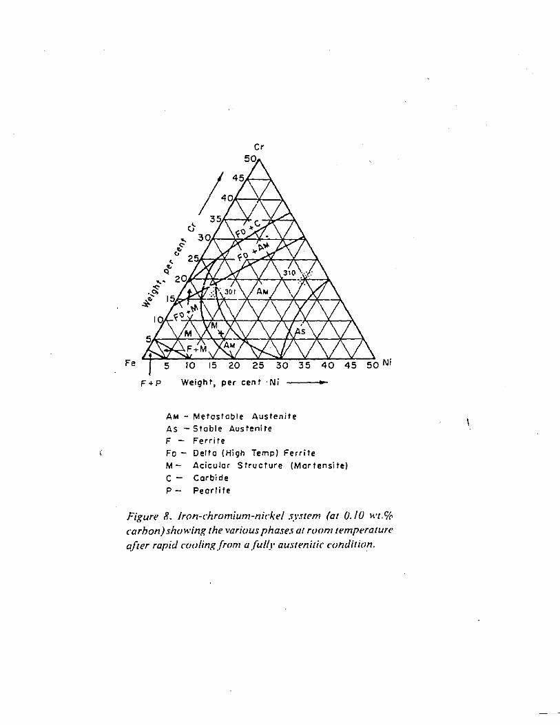
F+P Weight, per cent ·Ni
AM - Metastable Austenite
As -Stable Austenite
F - Ferrite
Fo- Delta (High Temp) Ferrite
M- Acicular Structure (Martensite)
C - Carbide
P- Pearlite
Figure 8. Iron-chromium-nickel system (at 0.10 wt.% carbon) showing the various phases at room temperature after rapid cooling from a fully austenitic condition.
1000 0 0
UJ a: 800 :J I-<{ a: UJ 600 Q.. ~ UJ I- 400
200
1832 -I m s;:
1472 '"'0 m :::0
~ 1112 c
:::0
' m -' 0
752 ,
' \ 392
oc \ \
\
30 20 10 0 % CR
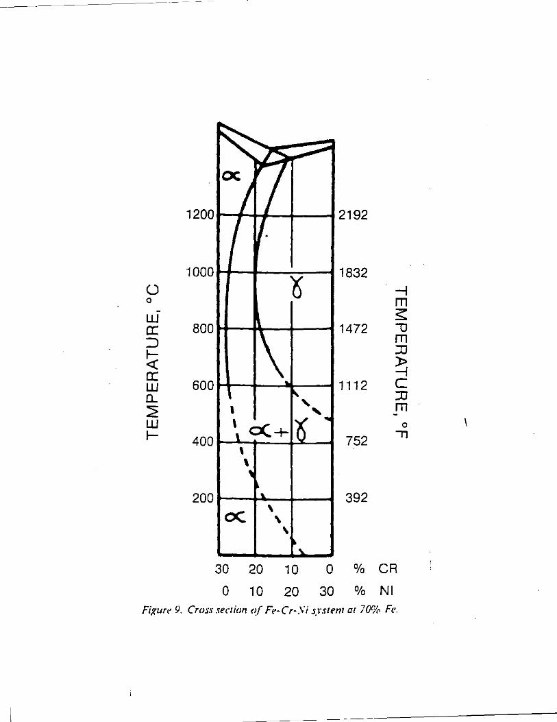
0 10 20 30 % Nl Fixure 9. Cross seer ion of Fe-t"r-Si srsrem ar 70% Fe. . .
I I I I I I I I I I I . I .
1-. a+L ·BI Q
a+y+L ~ ~ HI ..-- Y+L O+y Jl
1-
0 871 0
N2 y ----1-
1- ~bide ...----Q.l Gl ..... ::J -ro ..... Q.l a. E G2 Q.l
426 I-
~· 51 -----Q --- 5 f-+ -2
1-y a + r + Carbide
1'---- ,. Q ------------P2
r-
Q + Carbide 93 I 01 I I I I I I I I I I I .
• 0 0.1 0.2
Weight Percent Carbon
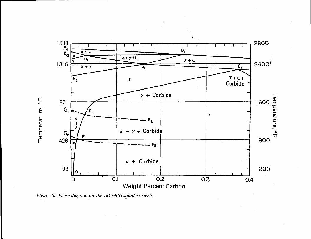
Fi!{ure Ill. Phase diuwum /cJr the 18Cr-8Ni stainless steels. . -
I I I I
-
El
"' Y+L+ Carbide -
-
-. --
-
-
-I I I I
0.3 0.4
2800
2400 1
-1 <D
1600 3 "'0
<D
BOO
200
..... Ill ..... c ..... <D
0
11
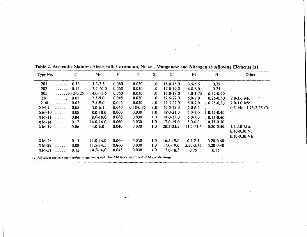
Table 1. Austenitic Stainless Steels with Chromium, Nickel, Manganese and Nitrogen as Alloying Elements (a)
Type No. c Mn p s Si Cr Ni N Dlher
201 0.15 5.5-7.5 0.060 0.030 1.0 16.0-18.0 3.5c5.5 0.25 202 0.15 7.5-10.0 0.060 0.030 1.0 17.0-19.0 4.0-6.0 0.25 205 ...... 0.12-0.25 14.0-15.5 0.060 0.030 1.0 16.0-18.0 1.0-1.75 0.32-0.40 216 0.08 7.5-9.0 0.045 0.030 1.0 17.5-22.0 5.0-7.0 0.25-0.50 2.0·3.0 Mo 2161. 0.03 7.5-9.0 0.045 0.030 1.0 17.5-22.0 5.0-7.0 • 0.25-0.50 2.0·3.0 Mo
XM-1 0.08 5.0-6.5 0.040 0.18-0.35 1.0 16.0-ll!.O 5.0-6.5 i
0.5 Mo. 1.75-2.25 Cu XM-10 0.08 8.0-10.0 0.060 0.030 1.0 18~0-21.0 5.0-7.0 I 0.15-0.40 XM-11 0.04 l!.0-1 0.0 0.060 0.030 1.0 18.0-21.0 5.0-7.0 . 0.15-0.40 XM-14 0.12 14.0-16.0 0.060 O.OJO 1.0 17.0-19.0 5.0-6.0 • 0.35-0.50 XM-19 0.06 4.0-6.0 0.040 0.030 1.0 20.5-23.5 11.5-IJ.5 0.20C0.40 1.5·3.0 Mo.
0.10·0.30 V, 0.10-0.30 N h
XM-28 0.15 11.0-14.0 0.060 0.030 1.0 16.5-19.0 0.5-2.5 0.20-0.40 XM-29 0.08 11.5-14.5 O.G60 0.030 1.0 17.0-19.0 2.50-3.75 0.20-0.40 XM-31 0.12 14.5-16.0 0.045 0.030 1.0 17.0-18.5 0.75 0.35
(a) All values arc maximum unless ran,:cs arc sl~tcd. The XM lypes arc from ASTM spccilic:..tinns.
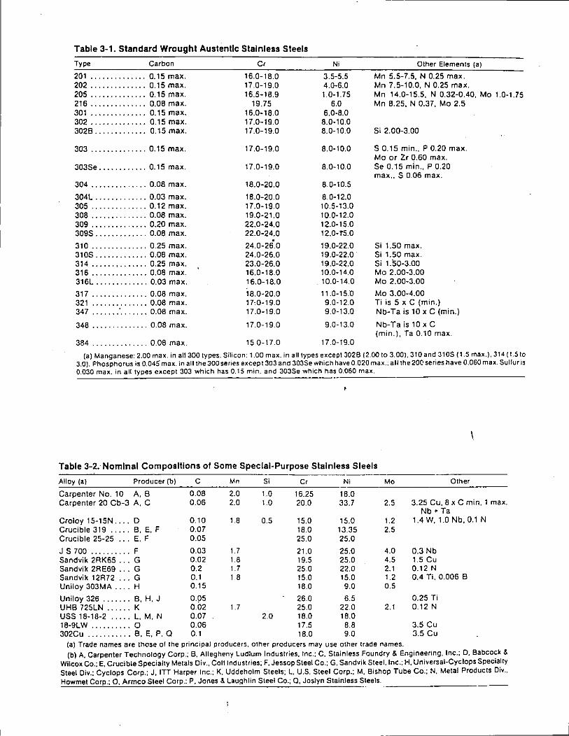
Table 3-1. Standard Wrought Austenllc Stainless Steels
Type Carbon Cr
201 .............. 0.15 max. 16.0-18.0 202 .............. 0.15 max. 17.0-19.0 205 .............. 0.15 max. 16.5-18.9 216 .............. 0.08 max. 19.75 301 .............. 0.15 max. 16.0-18.0 302 .............. 0.15 max. 17.0-19.0 3028 ............. 0.15 max. 17.0-19.0
303 .............. 0.15 max. 17.0-19.0
303Se ............ 0.15 max. 17.0-19.0
304 .............. 0.08 max. 18.0-20.0
304L ............. 0.03 max. 18.0-20.0 305 .............. 0.12 max. 17.0-19.0 308 .............. 0.08 max. 19.0-21.0 309 .............. 0.20 max. 22.0-24.0 309S ............. 0.08 max. 22.0-24.0
310 .............. 0.25 max. 24.0-26.0 310S ............. 0.08 max. 24.0-26.0 314 ...... , ....... 0.25 max. 23.0-26.0 316 .............. 0.08 max. 16.0-18.0 316L ............. 0.03 max. 16.0-18.0
317 .............. 0.08 max. 18.0·20.0 321 .............. 0.08 max. 17·.0·19.0 347 ...... .' ....... 0.08 max. 17.0-19.0
348 .............. 0.08 max. 17.0-19.0
384 .............. 0.08 max. 15.0-17.0
Ni
3.5-5.5 4.0-6.0 1.0-1.75
6.0 6.0-8.0
8.0-10.0 8.0-10.0
8.0-10.0
8.0-10.0
8.0-10.5
8.0-12.0 10.5-13.0 10.0-12.0 12.0-15.0 12.0-r5.0
19.0-22.0 19.0-22.0 19.0-22.0 10.0-14.0
. 10.0-14.0
11.0-15.0 9.0·12.0 9.0-13.0
9.0-13.0
17.0-19.0
Other Elements (a)
Mn 5.5-7.5, N 0.25 max. Mn 7.5-10.0, N 0.25 max. Mn 14.0-15.5, N 0.32·0.40, Mo 1.0·1.75 Mn 8.25, N 0.37, Mo 2.5
Si 2.00-3.00
S 0.15 min., P 0.20 max. Mo or Zr 0.60 max. Se 0.15 min., P 0.20 max .. S 0.06 max.
Si 1.50 max. Si 1.50 max. Si 1.50-3.00 Mo 2.00·3.00 Mo 2.00-3.00
Mo 3.00-4.00 Ti is 5 x C (min.) Nb-Ta is 10 x C (min.)
Nb-Ta is 10 x C (min.), Ta 0.10 max.
{a) Manganese: 2.00 max. in all300 types. Silicon: 1.00 max. in all types except 3026 {2.00 to 3.00), JtOand 3105 (1.5 max.), 314 (t.Sto 3.0). Phosphorus is 0.045 max. in all the 300 series except 303 and 303Se which have 0.020 max .. all the 200 series have 0.060 max. Sulfur is 0.030 max. in all types except 303 which has 0.15 min. and 303Se which has_o~.0:..:6:..:0_m_a:_x:_. ______________ _
Table 3-2.- Nominal Compositions of Some Special-Purpose Stainless Steels
Alloy (a) Producer (b) c Mn Si Cr Ni Mo Other
Carpenter No. 10 A, 8 0.08 2.0 1.0 16.25 18.0 Carpenter 20 Cb-3 A, C 0.06 2.0 1.0 20.0 33.7 2.5 3.25 Cu. 8 x C min. 1 max.
Nb + Ta Croley 15·15N .... 0 0.10 1.8 0.5 15.0 15.0 1.2 1.4 W, 1.0 Nb, 0.1 N Crucible 319 ..... 8, E, F 0.07 18.0 13.35 2.5 Crucible 25-25 ... E. F 0.05 25.0 25.0
J S 700 .......... F 0.03 t .7 21.0 25.0 4.0 0.3 Nb Sandvik 2RK65 ... G 0.02 1.8 19.5 25.0 4.5 1.5 Cu Sandvik 2RE69 ... G 0.2 t.7 25.0 22.0 2.1 0.12 N Sandvik 12R72 ... G 0.1 t.8 15.0 15.0 1.2 0.4 Ti. 0.006 8 Uniloy 303M A .... H 0.15 18.0 9.0 0.5
Uniloy 326 ....... 8, H, J 0.95 26.0 6.5 0.25 Ti UHB 725LN ...... K 0.02 t .7 25.0 22.0 2.1 0.12 N uss 18·18·2 ..... L, M, N 0.07 2.0 18.0 18.0 18-9LW .......... 0 0.06 17.5 8.8 3.5 Cu 302Cu ........... 8, E, P. Q 0.1 18.0 9.0 3.5 Cu
(a) Trade names are those of the principal producers, other producers may use other trade names. (b) A, Carpenter Technology Corp.; B. Allegheny Ludlum Industries. Inc.; C. Stainless Foundry & Engineering, Inc.; D, Babcock &
Wilcox Co.: E, Crucible Specialty Metals Oiv., Coli Industries; F, Jessop Steel Co.; G. Sandvik Steel.lnc.: H, Universal-Cyclops Specialty Steel Oiv.: Cyclops Corp.; J, ITT Harper Inc.: K. Uddeholm Steels; L, U.S. Steel Corp.; M. Bishop Tube Co.: N. Metal Products Div .. Howmet Corp.; 0, Armco Steel Corp.: P. Jones & Laughlin Steel Co.; 0, Joslyn Stainless Steels. ---------·---
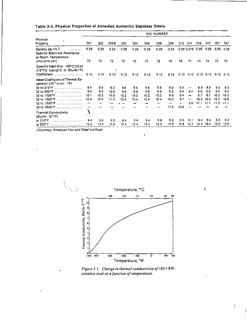
Table 3-3. Physical Properties of Annealed Austenitic Stainless Steels
AISI NUMBER
Physical
Property 301 302 3028 303 304 305 308 309 310 314 316 317 321 347
Density (lb./in. 1) 0.29 0.29 0.29 0.29 0.29 0.29 0.29 0.29 0.29 0.279 0.29 0.29 0.29 0.29 Specific Electrical Resistance at Room Temperature (microhm-em) 72 72 72 72 72 72 72 78 78 77 74 74 72 73
Specific Heat (0 to 1oo•c [32 to 212"F)) (cal/goc or Btu/lb.°F) Coefficient .......... 0.12 0.12 0.12 0.12 0.12 0.12 0 12 0.12 0.12 0 12 0.12 0.12 0.12 0.12
Mean Coefficient of Thermal Ex-pension (10' 6 in./in.- °F) 32to2t2•F ....... 9.4 9.6 9.0 9.6 9.6 9.6 9.6 8.8 8.0 8.9 8.9 9.3 9.3 32 to sao• F ....... ........... 9.5 9.9 10.0 9.9 9.9 9.9 9.9 9.3 9.0 8.4 9.0 9.0 9.5 9.5 32 to 1000"F ....... . . . . . . . . . . 10.1 10.2 10.8 10.2 10.2 10.2 10.2 9.6 9.4 9.7 9.7 10.3 10.3
32to 1200"F .. 10.4 10.4 , 1.2 10.4 10.4 10.4 10.4 10.0 9.7 10.3 10.3 10.7 10.6 32 to tsoo·F ...... 98 11. 1 1, .1 11.2 11.1
32to 1800"F ............ 11.5 10.6
Thermal Conductivity \ (Btu/hr. ·ft1·°F) at 212"F ·····-····· ·········· 9.4 9.4 9.2 9.4 94 94 8.8 90 8.2 10.1 9.4 9.4 9.3 9.3
at 932" F . . . . . . . . . . . . . . . . . . . . . 12.4 12.4 12.5 12.4 12.4 12 4 12.5 10.8 10.8 12.1 12.4 12.4 12.8 12.8 ------ ---- --- ------
(Courtesy, American Iron and Steel Institute)
Temperature, o C
~ " -ISS -129 .7J ·18 " 65
~ 10
~ 9 , iii i;7 :~ 6 u , " c 0 • 0
• § ' ~
"' 1- I
0 _.,., -400 ·300 ·200 ·100 0 100 150
Temperature, oF
Figure3-l. Change in rhermal conducrivity of 18Cr-8Ni stainless sreel as a function of temperature.
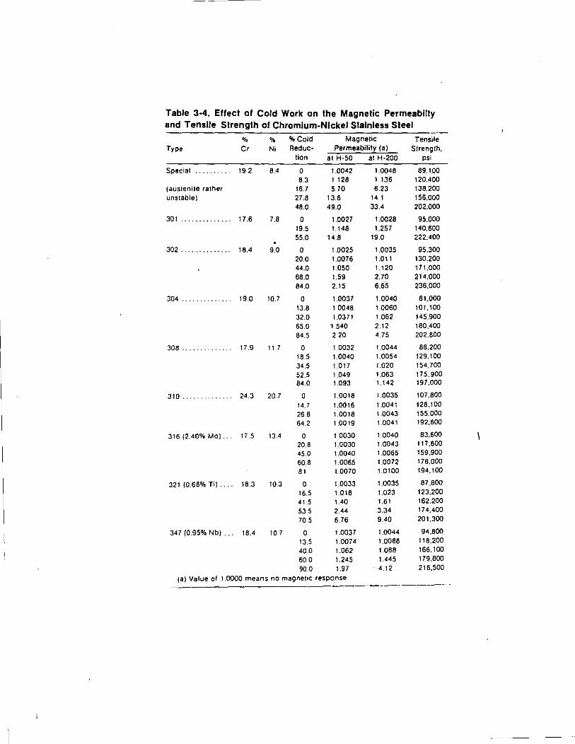
Table 3·4. Effect of Cold Work on the Magnetic Permeabllty and Tensile Strength of Chromium-Nickel Slalnless Steel
% 'lo %Cold Magnetic Tensile Type Cr Ni Reduc- Permeability (a) Strength,
lion at H-50 at H-200 psi
Special 19 2 8.4 0 1.0042 1.0048 89.100 8.3 1 128 1 136 120.400
(austenile rather 16.7 5.70 6.23 138.200 unstable) 27.8 13.6 14.1 156,000
48.0 49.0 33.4 202.000
301 .............. 17.6 7.8 0 1.0027 1.0028 95,000 19.5 1.148 1.257 140,600 55.0 14.8 19.0 222,400
302 .............. 18.4 9.0 0 1.0025 1.0035 95,300 20.0 1.0076 1.011 130.200 44.0 1.050 1.120 171,000 68.0 1.59 2.70 214,000 84.0 2.15 6.65 236,000
304 " " " " " " " 19.0 10.7 0 1.0037 1.0040 81,000 13.8 1.0048 1.0060 101,100 32.0 1.0371 1.062 145.900 65.0 1.540 2.12 180,400
84.5 2 20 4 75 202.800
JOB 17.9 11.7 0 1.0032 1.0044 88,200 18.5 1.0040 1.0054 129. tOO
34.5 1.017 1.020 154.700 52.5 1.049 1.063 175.900 84.0 1.093 1.142 197,000
310 .. 24.3 20.7 0 1.0018 1.0035 107,800
14.7 1.0016 1.0041 128.100 26.8 1.0018 1.0043 155.000
64.2 1.0019 1.0041 192,600
316 (2.40% MO). li 5 13.4 0 1.0030 1 0040 83.600
20.8 1.0030 1.0043 117,800
45.0 1.0040 1.0065 159.900
60.8 1.0065 1.0072 178,000
81 1.0070 1.0100 194,100
321 {0.68% Ti) .... 18.3 10.3 0 1.0033 1.0035 87,800
16.5 1.018 1.023 123,200
41.5 1.40 1.61 162.200
53.5 2.44 3.34 174,400
705 6.76 9.40 201.300
347 (0.95% Nb) ... 18.4 10 7 0 1.0037 1.0044 94.800
13.5 1.0074 1.0088 118.200
40.0 1.062 1.088 166,100
60.0 1.245 1.445 179.SOO
90.0 1.97 4.12 216.500
(a) Value of 1.0000 means no magnet•c response ----------·
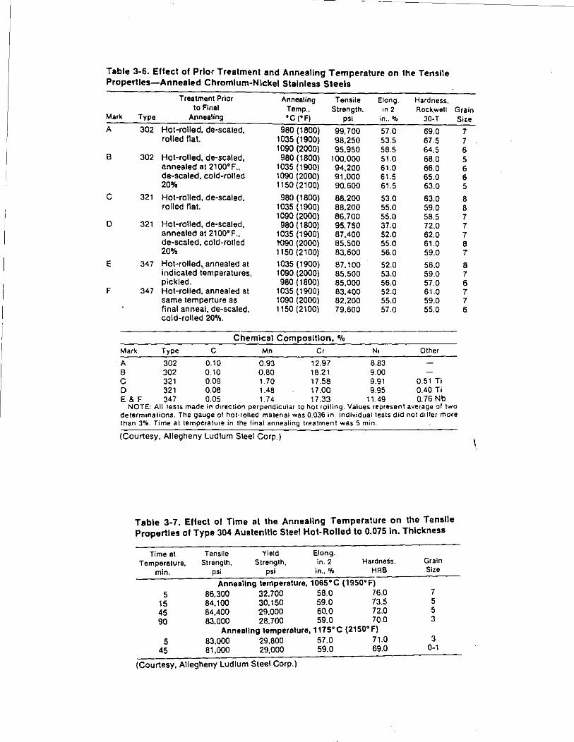
Table 3-6. Effect of Prior Treatment and Annealing Temperature on the Tensile Properties-Annealed Chromium-Nickel Stainless Steels
Treatment Prior Annealing Tensile Elong. Hardness. to Final Temp., Strength,
'" 2 Rock.well Grain
Mark Type Annealing •c ('Fl psi in .. % 30-T Siz.e A 302 Hot-rolled. de-scaled, 980 (1800) 99,700 57.0 69.0 7
rolled !Ia t. 1035 (1900) 98,250 53.5 67.5 7 1090 (2000) 95,950 58.5 64.5 6
B 302 Hot-rolled, de-scaled. 980 (1800) 100,000 51.0 68.0 5 annealed at 2100'F., 1035 (1900) 94,200 61.0 66.0 6 de-scaled, cold-rolled 1090 (2000) 91.000 61.5 65.0 6 20% 1150 (2100) 90,600 61.5 63.0 5
c 321 Hot-rolled, de-scaled. 980 (1800) 88.200 53.0 63.0 8 rolled flat. 1035 (1900) 88,200 55.0 59.0 8
1090 (2000) 86,700 55.0 58.5 7 D 321 Hot-rolled, de-scaled, 980 (1800) 95,750 37.0 72.0 7
annealed at 2100'F .. 1035 (1900) 87,400 52.0 62.0 7 de-scaled, cold-rolled 1'090 (2000) 85,500 55.0 61.0 8 20% 1150 (2100) 83,600 56.0 59.0 7
E 347 Hot-rolled,, annealed at 1035 (1900) 87,100 52.0 58.0 8 indicated temperatures, 1090 (2000) 85,500 53.0 59.0 7 pickled. 980 (1800) 85,000 56.0 57.0 6
F 347 Hot-rolled, annealed at 1035 (1900) 83,400 52.0 61.0 7 same temperture as 1090 (2000) 82.200 55.0 59.0 7 final anneal, de-scaled. 1150 (2100) 79.600 57.0 55.0 6 cold-rolled 20%.
Chemical Composition, %
Mark Type c Mn Cr Ni Other
·A 302 0.10 0.93 12.97 8.83 B 302 0.10 0.80 18.21 9.00 c 321 0.09 1.70 17.58 9.91 0.51 Ti D 321 0.08 1.48 17.00 9.95 0.40 Ti E&F 347 0.05 1.74 17.33 11.49 0.76 Nb
NOTE: All !ests made in direction perpendicular to hot rolling. Values represent average ol two determinations. The gauge ol hoi-rolled matenal was 0.036 in. Individual tests did not ddler more than 3%. Time at temperature in the final annealing treatment was 5 min.
(Courtesy, Allegheny Ludlum Steel Corp.)
Table 3-7. Effect ol Time al the Annealing Temperature on the Tensile Properties of Type 304 Austenitic Steel Hot-Rolled to 0.075 ln. Thickness
Time at Temperature,
min.
5 15 45 90
5 45
Tensile Yield Elong. Strength. Strength, in. 2 Hardness.
psi psi in., % HRB
Annealing temperature, 1065' C (1950' F) 86.300 32,700 58.0 76.0 84.100 30,150 59.0 73.5 84,400 29.000 60.0 72.0 83,000 28,700 59.0 70.0
Annealing temperatura, 1175" C (2150" F) 83,000 29.800 57.0 71.0 81,000 29,000 59.0 69.0
(Courtesy, Allegheny Ludlum Steel Corp.)
Grain Size
7 5 5 3
3 0-1
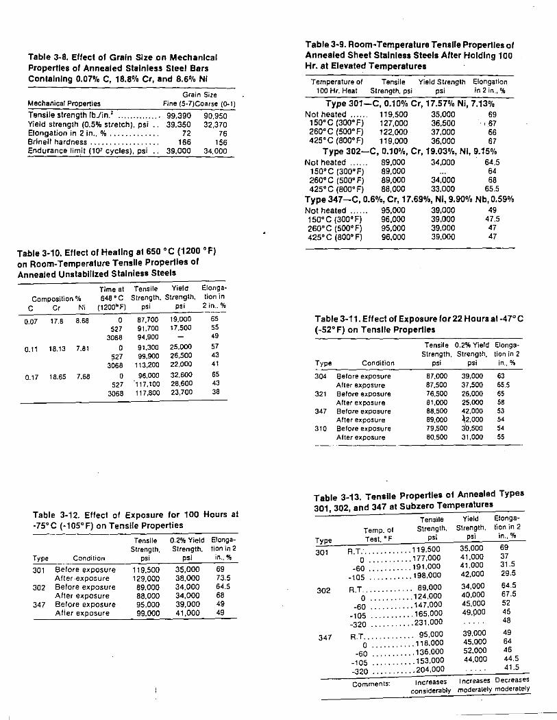
Table 3-8. Effect of Grain Size on Mechanical Properties of Annealed Stainless Steel Bars Containing 0.07% C, 18.8% Cr, and 8.6% Nl
Grain Size Mechanical Properties Fine (5-7)Coarse {Q..I)
Tensile strength lb./in.' ............. . 99,390 90,950 Yield strength (0.5% stretch), psi .. 39.350 32,370 Elongation in 2 in., % ............ . 72 76 Brinell hardness ................. . 166 156 Endurance limit (107 cycles). psi •. 39,000 34,000
Table 3·1 0. Effect of Heating at 650 • C (1200 • F) on Room-Temperature Tensile Properties of Annealed Unstablllzed Stainless Steels
Time at Tensile Yield Elonga-
Composition% 648 oc Strength. Strength, tion in
c Cr Ni (1200'F) psi psi 2 in .. %
0.07 17.8 8.68 0 87,700 19,000 65 527 91.700 17,500 55
3068 94,900 49
0.11 18.13 7.81 0 91.300 25.000 57 527 99,900 26,500 43
3068 113,200 22.000 41
0.17 18.65 7.68 0 96,000 32,600 65 527 117,100 28,600 43
3068 117,800 23,700 38
Table 3-12. Effect of Exposure for 100 Hours at -75" C (·1 as• F) on Tensile Properties
Tensile 0.2% Yield Elonga-Strength, Strength, tion in 2
Type Condition psi psi in .. % ---··-· 301 Before exposure 119,500 35,000 69
After-exposure 129.000 38,000 73.5 302 Before exposure 89.000 34.000 64.5
After exposure 88,000 34,000 68 347 Before exposure 95,000 39,000 49
Aller exposure 99,000 41,000 49
Table 3-9. Room· Temperature Tensile Properties of Annealed Sheet Stainless Steels After Holding 100 Hr. at Elevated Temperatures
Temperature at Tensile Yield Strength Elongation 100 Hr. Heat Strength, psi psi in 2 in.,%
Type 301-C, 0.10% Cr, 17.57% Ni, 7.13% Not heated ...... 119,500 35,000 69 150" C (300" F) 127,000 36,500 , 67 260"C (500"F) 122,000 37,000 66 425"C (800"F) 119,000 36,000 67
Type 302-C, 0.10%, Cr, 19.03%, Nl, 9.15% Not heated .. . . . . 89,000 34,000 64.5
150" C (300" F) 89,000 64 260" C (500" F) 89,000 34,000 68 425" C (800" F) 88,000 33,000 65.5
Type 347-C, 0.6%, Cr, 17.69%, Nl, 9.90% Nb, 0.59% Not heated .. .. .. 95,000 39,000 49 150"C (300"F) 96,000 39,000 47.5 260"C (500" F) 95,000 39,000 47 425" C (800" F) 96,000 39,000 47
Table 3-11. Effect of Exposure for 22 Hours at -47" C (-52" F) on Tensile Properties
Tensile 0.2% Yield Elonga-Strength, Strength, tion in 2
Type Condition psi psi in.,%
304 Before exposure 87,000 39,000 63 Alter exposure 87,500 37,500 65.5
321 Before exposure 76,500 26,000 65 After exposure 81,000 25,000 58
347 Before exposure 88,500 42,000 53 After exposure 89,000 ~.2.000 54
310 Before exposure 79.500 30.500 54 After exposure 80,500 31,000 55
Table 3-13. Tensile Properties of Annealed Types 301, 302, and 347 at Subzero Temperatures
Tensile Yield Elonga-
Temp. of Strength. Strength. lion in 2
Type Test. D F psi psi in.,%
301 R.T.· ............ 119.500 35,000 69
0 ........... 177.000 41,000 37 -60 ...... " ... 191,000 41.000 31.5
-105 ........... 198,000 42.000 29.5
302 R.T. ............ 89,000 34,000 64.5
0 ........... 124.000 40,000 67.5
-60 ........... 147,000 45,000 52
-105 ........... 165.000 49.900 45
-320 ........... 231,000 48
347 R.T ......... · .. · 95,000 39,000 49
0 ........... 118,000 45,000 64
-50 ......... "136.000 52,000 46
-105 ......... "153.000 44,000 44.5
-320 ......... "204,000 41.5
Comments: Increases Increases Decreases considerably moderately moderately
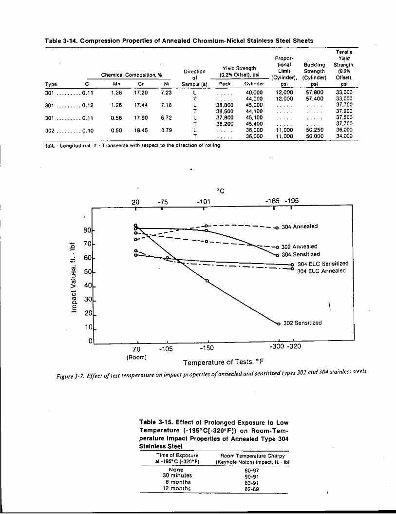
Table 3·14. Compression Properties ol Annealed Chromium-Nickel Stainless Steel Sheets
Yield Strength Direction
Chemical Composition, % of {0.2% Olfset). psi
Type c Mn Cr Ni Sample{a) Pack Cylinder
301 ......... 0.11 1.28 17.20 7.23 L 40,000 T 44,000
301 ......... 0.12 1.26 17.44 7.18 L 38.800 45.000 T 38.500 44,100
301 ......... 0.11 0.56 17.90 6.72 L 37,800 45,100 T 38.200 45.400
302 ......... 0.10 0.50 18.45 8.79 L 36.000 T 36.000
(a)L- Longitudinal: T- Transverse with respect to lhe direction of rolling.
::c ::: IIi
·Ql :J iii > -() "' a. E
80
70
60
50
40
30
20
10
0
20
70 (Room)
·c -75 -101
-105 -150
Temperature of Tes:s. • F
Proper-tional Buckling Limit Strength
{Cylinder), {Cylinder) psi psi
12.000 57,800 12,000 57.400
11,000 50.250 11,000 50.000
-185 -195
302 Sensi1ized
-300 -320
Tensile Yield
Strength. {0.2%
Olfset), psi
33.000 33,000 37,700 37.900 37.500 37.700 36,000 34.000
Figure 3-2. Effect of test temperature on impact properties of annealed and sensitized types 302 and 304 stainless steels.
Table 3-15. Effect ol Prolonged Exposure to Low
Temperature (·195"C[-320"F]) on Room-Tem
perature Impact Properties ol Annealed Type 304 Stainless Steel
Time of Exposure at ·195'C {-320'F)
None 30 minutes 6 months
12 months
Room Temperature Charpy (Keyhole Notch) Impact. ft. · lbl
80·97 90·91 83·91 82·89
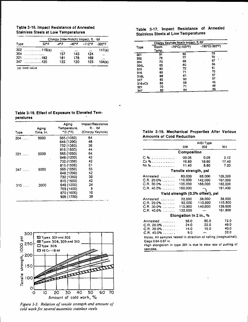
T~ble 3-16.1mpacl Resistance of Annealed Stainless Steels at Low Temperatures
Charpy (Vee-Notch) Impact. ft. · lbf
Type 32°F -4° F -4o•F -tt2•F -3oo•F 302 .. 119(a) 117(a) 304 157 143 124 321 .. 182 181 178 169 347 .. 120 122 120 123 t04(a)
(a) lzod value
Table 3-18. Eflect of Exposure to Elevated Tern-peratures
Aging Impact Resistance Aging Temperature. ft. . lbf
Type Time, hr. ·c (•F) (Charpy Keyhole)
304 .
321 ....
347
310
~ ·;;; 100 c: ~
0 0
5000 565 (1050) 64 648 (1200) 48 732 (1350) 36 815 (1500) 44
5000 565 (1050) 64 648 (1200) 42 732 (1350) 42 815 (1500) 51
5000 565 (1050) 55 648 (1200) 42 732 (1350) 39 815 (1500) 42
3000 648 (1200) 24 759 (1400) 8 870 (1600) 10 926 (1700) 38
·-------
S Types 30 I and 302
11!11 Types 308,309 ond 310 ---1f--+---1 0Type 305
C 16Cr-18NI
10 20 30 40 50 60 70 Amount of cold work, %
Figure 3-3. Relation of tensile strength and amount of cold work for several austenitic stainless Sll'els.
Table 3-17. Impact Resistance of Annealed Stainless Steels at Low Temperatures
Charpy Keyhole Notch Impact, fl·lbf
Type Room -76°C(-105°F) -195°C(·320•F) Tern.
301 91 92 79
302 75 77 70
304 70 68 67
304L 65 60 56 61 310 80 72
316 80 71 70
316L 68 61 57 57 317 82 90
316+Cb 68 58 45 48 321
347 70 71 60 54 55
Table 3-19. Mechanical Properties Aller Various Amounts of Cold Reduction
A lSI Type 308 302 301
Composition c %........ .. .. . . 00.05 0.09 0.12 Cr%............. 19.80 18.60 17.40 Ni% . . . . . . . . . . . . . 11.40 8.80 7.20
Tensile strength, psi Annealed . . . . . . . . 80,000 88,000 126,300 C. A. 20.0% . . . . . . . 110,000 142.000 167,000 C. A. 30.0% . . . . . . . 135,000 168,000 182.200 C. A. 40.0% . . . . . . . 160,000 -
1 191.400
Yield strength (0.2% offset), psi Annealed ....... . C.R. 20.0% ...... . C. A. 30.0% ...... . C.R. 40.0% ... .
32.000 92,000
115.000 132.000
38,000 110.000 140,000
Elongation In 2 ln., %
Annealed . . . . . . . . 58.0 60.0 C.R. 20.0% . . . . . . . 24.0 22.0 C.R. 30.0% . . . . . . . 14.0 15.0 C. A. 40.0% . . . . . . . 9.0
38.600 115.800 139.800 161.800
72.0 49.0 40.0 32.0
Notes. All samples tested in direction of rotting (longitudinal); Gage 0.04-0.07 in. High elongation in type 301 is due to slow rate of pulling of samples.

r----------------------------------------------------------------------------- -----
2101,-------------------------------~
120
90
60 Proportional Umit
0 25
~ 20 E!onQalion ~ .c 15 u E
10
"' s 5
0 " 0 a ~- 2• • ~ ~ M ~ n Hours at 175° C (350° F)
Figure 3·4. Effect of holding time at 175' C (350' F) on· mer/lanical properties of type 301 stainless steel.
Table 3-21. Effect of Cold-Rolling Temperature on work-Hardening
Holling Tfl•nperature.
·c i"Fl
Reduction AoomTemperature Elongation by Roll- Tensile Strength, in 2 in. ing,% psi ~
Ruom 60.0 178,500 6.0 (-105) 26.8 169,700 15.0 ( .;i20:cl ______ 1:.::8:.::.3~ __ _:_16::.;9:.:,8::.;0:.::0 ___ 2:.::2:.::.0~-
G• •fllPOSition: Type 302: C 0.11: Cr 17 .88; Ni 9.95 Tlllckness of the test samples: 0.040 in.
Table 3-20. Compression Properties of Two Types of Stainless Steels Annealed and Cold-Rolled 35%
Direction ol Test
302
Composition
Alloy Type
C%...................... 0.10 Cr%..................... 18.45 Ni%..................... 8.80
Modulus of elasticity, 1 o' pal
301
0.11 17.15 7.20
Annealed ... L 28.0 28.0 T 28.0 29.0
C.R. 35% .... L 26.0 26.0 T 27.0 27.0
Yield strength (0.2% offset), psi Annealed ... L 36,000 40,000
T 36.000 44,000 C.R. 35% .... L 95.000 139.000
T 149,000 185.000
Buckling strength, psi Annealed ... L 50.250
T 50.000 C.R. 35% .... L 151,800
T 183,110
57.800 57,400
184.500 214.300
Table 3-22. Effect of Temperature on Strength and Ductility of Annealed and Cold-Worked Stainless Steel
Temper- Tensile Yield Strength Elongation
ature Strength. (0.2% in 2 in ..
Type of Test psi Offset), psi % ·--·--
302 Annealed Room 89,000 34.000 67 0' F 124.000 40.000 67.5
-60" F 147.000 45.000 52 (a)
302 1/7-hard Room 155.000 150.000 14 o•F 161,000 157.000 33
-60' F 181,000 157,000 38
(a) 0.350 in w1de. All others 0.500 in. wide. - ·---------
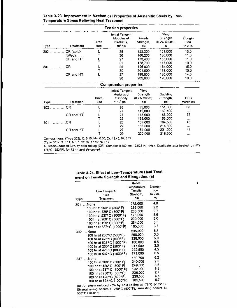
Table 3-23. Improvement In Mechanical Properties of Austenitic Steels by LowTemperature Stress Relieving Heat Treatment
····----------- -·-·---Tension properties
-·--- -- ---- - ·------------·-lnilial Tangent Yield
Modulus of Tensile Strength e"Jonga-Oirec- Elasticity. Strength. (0.2% Ollset). lion
Type Treatment lion 106 psi psi % in 2 in. ---·- ---·-302 . .. CR (cold- L 26 155.300 131.000 15.0
rolled) T 30 166.200 130,000 11.0 CR and HT L 27 173.400 155,000 . 11.0
T 31 178.700 147.000 10.0 301 ... CR L 26 196.000 164.000 15.0
T 30 201.000 13B.OOO 10.0 CR and HT L 27 198.000 1BO.OOO 14.0
T 30 202.000 170.000 10.0
Compression properties
Initial Tangent Yield Modulus of Strength Buckling
Direc- Elasticity. {0.2% Offset). Strength. HAC Type Treatment tion • 10' psi psi psi Hardness
302. .. CR L 26 95,000 151.BOO 36 T 27 149.000 1B3.100
CR and HT L 27 118.000 15B.OOO 37 T 29 169.000 193,000
301 .. CR L 26 139,000 184,500 43 T 27 185,000 214,300
CR and HT L 27 161,000 201,200 44 T 29 200,000 21B,500
Compositions: (Type 302): C. 0.10; Mn. 0.50; Cr. 18.45; Ni. 8.79 (Type 301): C. 0.11; Mn. 1.32; Cr. 17. 15; Ni 7.17 All steels reduced 35% by cold rolling (CA). Samples 0.889 mm (0.035 in.) thick. Duplicate tests heated to (HT) 176_° C (350° F), for 72 hr. and air-cooled.
Table 3-24. Ellect of Low-Temperature Heal Treatment on Tensile Strength and Elongation. {a)
Room Temperature Elonga-
Low Tempera- Tensile tion
ture Strength, In 2 in ..
Type Treatment psi 'II
301 ... None 275.000 4.0 100 hr al 260" C (500" F) 2B6,000 2.2 100 hr at 426" C (BOO" F) 266,500 2.7 100 hr at 537"C (1000"F) 173,000 5.6 100 hr at 260"C (500"F) 290,000 3.0 100 hr at 426" C (BOO" F) 254,000 5.5 100 hr at 537"C (1000"F) 165,000 6.7
302 ... None 235,000 5.7 100 hr at 260"C (500"F) 250,000 3.0 100 hr ai426"C (BOO" F) 228.000 5.0 100 hr at 537"C (1000"F) 180,000 6.5 100 hr at 260"C (500"F) 247,500 3.0 100 hr ai426"C (BOO" F) 222,500 4.5 100 hr al 537" C (1000" F) 171,000 6.5
347 ... None 1B9,700 6.2 100 hr at 260"C (500"F) 240,000 2.5 100 hr ai426"C (800"F) 249,000 3.5 100hrat537"C (1000"F) 192.000 6.2 100 hr at 260"C (500"F) 236,000 2.7 100 hr a1426"C (800"F) 239,500 4.5 100 hr at 537"C (1000"F) 182,500 6.7
(a) All steels reduced 400fa by cold rolling at -76oC (-105°F). Strengthening occurs at 260° C (500° F), annealing occurs at
538"C (1000"F).
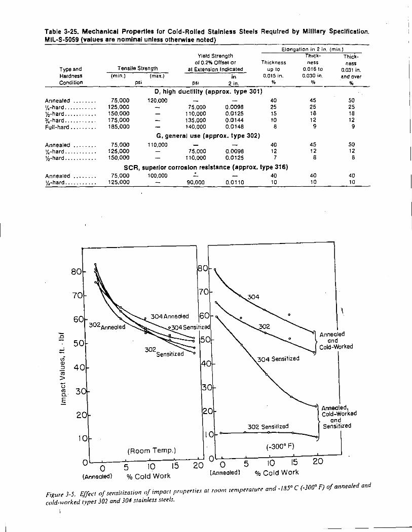
Table 3-25. Mechanical Properties for Cold-Rolled Stainless Steels Required by Military Specification. MIL-S-5059 (values are nominal unless otherwise noted)
Elongation in 2 in. (min.)
Type and Hardness Condilion
Annealed ....... . v4-hard .......... . v,-hard .......... . 3J4-hard .......... . Full-hard ........ .
Annealed ....... . 1/ 4-hard .......... . %-hard .......... .
Annealed ....... . v.~-hard .......... .
80
70
60
.c 50 -
ui "' 40 " "' > u "' 3 a. E
20
10
0 0
Yield Strength ot 0.2% Offset or
Tensile Strength at Extension Indicated in
Thickness up to
0.015 in.
% (min.) {max.)
75.000 125.000 150.000 175.000 185.000
75.000 125.000 150.000
psi psi 2 in.
D, high ductility (approx. type 301) 120.000 40
75.000 0.0098 25 110.000 0.0125 15 135.000 0.0144 10 140.000 0.0148 8
G, general use (approx. type 302) 110.000
75.000 110.000
0.0098 0.0125
40 12 7
SCR, superior corrosion resistance (approx. type 316) 75.000 100.000 • 40
125.000 90.000 0.0110 10
40 304 Sensitized
30
20
302 Sensitized 10
(Room Temp.) (-300° F)
5 10 15 20 ° 0 5 10 15
(Annealed) %Cold Work (Annealed) %Cold Work
Thi<;k- Thick-ness ness
0.016 to 0.031 in. 0.030 in. and over
% %
45 50 25 25 18 18 12 12
9 9
45 50 12 12
8 8
40 40 10 10
l-~"'· Cold-Worked ond
Sensitized
20
· d 185° C (-300° F) of annealed and Figure 3-5. Effect of sensitization of impact properties at room remperature an -
cold-worked types 302 and 304 .uainless steels.
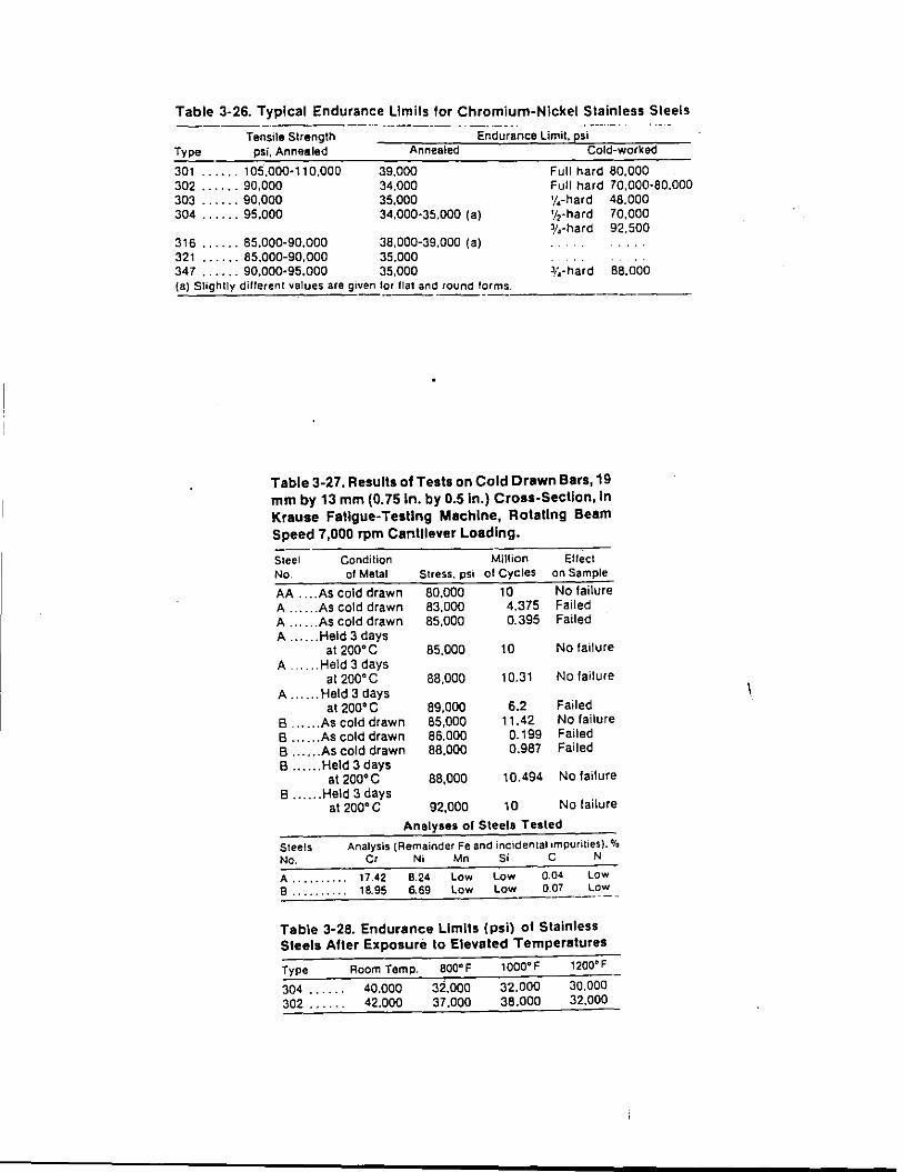
Table 3-26. Typical Endurance limits tor Chromium-Nickel Stainless Steels
Tensile Strength Type psi, Annealed
301 ...... 105,000-110.000 302 ...... 90.000 303 ...... 90,000 304 ...... 95.000
316 ...... 85.000-90.000 321 ...... 85.000-90.000 34 7 ...... 90,000-95,000
Endurance Limit, psi Annealed
39.000 34.000 35.000 34,000·35.000 (a)
38,000-39.000 (a) 35.000 35.000
Cold-worked
Full hard 80,000 Full hard 70,000-80.000 v,-hard 48.000 v,-hard 70,000 ~/4-hard 92.500
~~·hard 88.000 (a) Slightly dillerenl values are g1ven lor flat and round !arms. ----------'-----·
Table 3-27. Results of Tests on Cold Drawn Bars, 19 mm by 13 mm (0. 75 ln. by 0.5 ln.) Cross-Section, In Krause Fatigue-Testing Machine, Rotating Beam Speed 7,000 rpm Cantilever Loading.
Steel Condition Million Effect No. of Metal Stress. psi of Cycles on Sample
AA .... As cold drawn 80,000 10 No failure A ...... As cold drawn 83,000 4.375 Failed A ...... As cold drawn 85,000 0.395 Failed A ...... Held 3 days
at 200'C 85,000 10 No failure A. .... Held 3 days
at 200'C 88,000 10.31 No failure A ...... Held 3 days
at 200'C 89,000 6.2 Failed B ...... As cold drawn 85,000 1 1.42 No failure B ...... As cold drawn 86,000 0.199 Failed B ...... As cold drawn 88,000 0.987 Failed B ...... Held 3 days
al 200'C 88,000 10.494 No failure B ...... Held 3 days
at 200'C 92,000 10 No failure
Analyses of Steels Tested
A, .. ,...... 17.42 8.24 Low Low 8 . . . . . . . . . . 18.95 6.69 Low Low
0.04 007
Low LOW
Table 3-28. Endurance Limits (psi) of Stainless Steels After Exposure to Elevated Temperatures
Type Room Temp.
304 . . . . .. 40.000 302 . . . . . . 42.000
800 111 F
32.ooo 37,000
1Q00111 F
32.000 38.000
30.000 32,000

Table 3-5. Room-Temperature Mechanical Properties of Austenitic Stainless Steels (a)
Room Yield Tensile Temp. AtSt Strength, Strength, Elongation. Hardness
Jzod, Type Condition 1000 psi 1000 ps; (b) %in 2 in. BHN HAC tt. . tbt 201 ...... Ann 55 110 50 890 100 201 ...... cw to 140 to 185 50-8 to C41 202 ...... Ann 55 100 50 890 100 301 ...... Ann 40 110_ 60 165 885 100 301 ...... CW to 140 to 185 60-8 to C41 302 ...... Ann 40 90 55 155 882 100 302 ...... CW to 150 to 180 55-10 to CJ5 303 ...... Ann 35 90 55 160 884 85 303 ...... CW to 100 to 180 55-30 to 330 to C35 304 ...... Ann 35 85 55 150 880 100 304 ...... cw to t50 to 180 55-10 to 330 to C35 305 ...... Ann 37 85 55 156 882 100 JOB ...... Ann 35 85 55 150 880 100 308 ...... CW to 150 to 180 55-10 to 330 to C35 309 ...... Ann 40 90 65 165 885 100 310 ...... Ann 40 95 65 170 887 100 314 ...... Ann 50 100 40 180 890 90 314 ...... CW to 125 to 150 40-10 10 CJO 316 ...... Ann 35 85 55 150 880 90 316 ...... cw to 125 to 150 55-10 · to 300 to CJO 317 ...... Ann 40 90 55 160 885 90 321 ...... Ann 35 87 55 150 880 90 321 ...... cw to 125 to 150 55-10 to 300 to CJO 347 ...... Ann 35 92 50 160 884 90 347 ...... cw to 125 to 150 50-10 to 300 to C30 348 ...... Ann 35 92 50 160 884 90 (a) Austenitic stainless steels are annealed between 1010 and 1120" C (1 850and 2050" F). Properties for cold~worked steels are lor approximately %:-hard sheet. except lor 303, lor which. properties pertain to cold-drawn bar slack. (b) Yield strength at 0.2% offset.
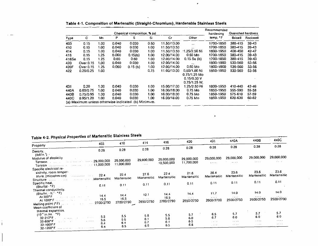
Table 4-1. Composition or Marlenslllc (Straight-Chromium), Hardenable Stainless Steels
Recommended Chemical composition.% (a) hardening Quenched hardness
Type c Mn p s Si Cr Other temp, of Brine \I Rockwell
403 0.15 1.00 0.040 0.030 0.50 11.50/13.00 1700-1850 380-415 39-43 410 0.15 1.00 0.040 0.030 1.00 11.50/13.50 1700-1850 380-415 39-43 414 0.15 1.00 0.040 0.030 1.00 11.50/13.50 ·1.25/2.50 Ni 1800-1950 400-450 42-47 416 0.15 1.25 0.060 0.15(b) 1.00 12.00/14.00 0.60 Mo 1700-1850 380-415 39-43 416Se 0.15 1.25 0.60 0.60 1.00 12.00/14.00 0.15 Se (b) 1700-1850 380-415 39-43 420 Over 0.15 1.00 0.040 0.030 1.00 12.00/14.00 1800-1900 530-560 53-56 420F Over 0.15 1.25 0.060 0.15(b) 1.00 12.00/14.00 0.60 Mo 1800-1900 530-560 53-56 422 0.20/0.25 1.00 0.75 11.00/13.00 0.50/1.00 Ni 1850-1950 530-560 53-56
0.75/1.25 Mo 0.15/0.30 v 0. 75/1.25 w.
431 0.20 1.00 0.040 0.030 1.00 15.00/17.00 1.25/2.50 Ni 1800-1950 410-440 42-46 440A 0.60/0.75 1.00 0.040 0.030 1.00 16.00/18.00 0.75 Mo 1850-1950 555-590 55-58 4408 0.75/0.95 1.00 0.040 0.030 1.00 16.00/18.00 0.75 Mo 1850-1950 575-610 57-59 440C 0.95/1.20 1.00 0.040 0.030 1.00 16.00/18.00 0.75 Mo 1850-1950 620-630 60·62 {a) Maximum unless otherwise indicated. (b) Minimum.
Table 4-2. Physical Properties or Marlensilic Stainless Steels 440C
416 420 431 4'0A 4408 403 410 414
Properly 0.28 0.28 0.28 0.28 0.28
0.28 0.28 0.28 Oens1ty, 0.28
{lbflin. 'l · 29,000.000 Modulus ol elasticity 29,000.000 29.000,000 29,000.000 29,000,000 29.000,000 29,000,000
Tension .. 29.000,000 29,000,000 10,500,000 11,700,000
Torsion . 11.000,000 11,000,000 Specific electrical re·
sistivity, room temper- 27.6 22.4 21.6 28.4 23.6 23.6 23.6 ature. (microhm-em) 22.4 22.4
Martensitic Martensitic Martensilic Martensilic Martensitic Martensitic Martensitic Martensitic Martensitic
Structure Specillc heat. 0.11 0.11 0.11 0.11 0.11 0.11
(Biu/lbl ·oF) 0.11 0.11 0.11
Thermal conductivily. (Btu/hr.· H.:· oF) 14.4 14.4 11.7 14.0 14.0 14.0
At 200° F 14.4 14.4 12.1 16.5 16.5 ....
At 1000° F .. 16.5 2650/2750 2600/2700 2500/2750 250012750 2500/2700 Melling point (° F) 2700/2790 2700/2790 2650/2750 2700/2790 -Mean coefficient of
thermal expansion. 5.7 ( 10·o ln./in. · "F) 5.5 5.7 6.5 5.7 5.7
32·212°F 5.5 5.5 5.8 6.7 6.0 60 60 5.6 56 61 5.6 6.0
32·600°F 6.4 6.4 6 7 6.<1 65 32-1000" F
6.4 6.5 6.9 6.5 6.8 32-1200" F
RANGE I ANGE 2 RANGE 3 RANGE 4
Slrns T~mpcorinq
"' ~tlitvin9 No! Used Anntalino Hardenino
~ r "' "' ~
"' c z . 0 0
"' • -< u :1; .:
Toughness
"' "' "' z ~ :1; c
"' • ::> 0 0 ~ ... u .:
"' ... Corros1on -<
"' z ~ c
Q ;;
"' 0 0 . "' ~ a: .: 0 u \-----'-----;-,-;'Low C~rbon Typ U 1
~~~20=5~1~400~1~4~2~5~1.:00;1~~6~50~11~20;0~1~8;.70~11;600~1-"'0~~(2~) REHEATING TEMPERATURE, •c (•F) •• Quenchtd
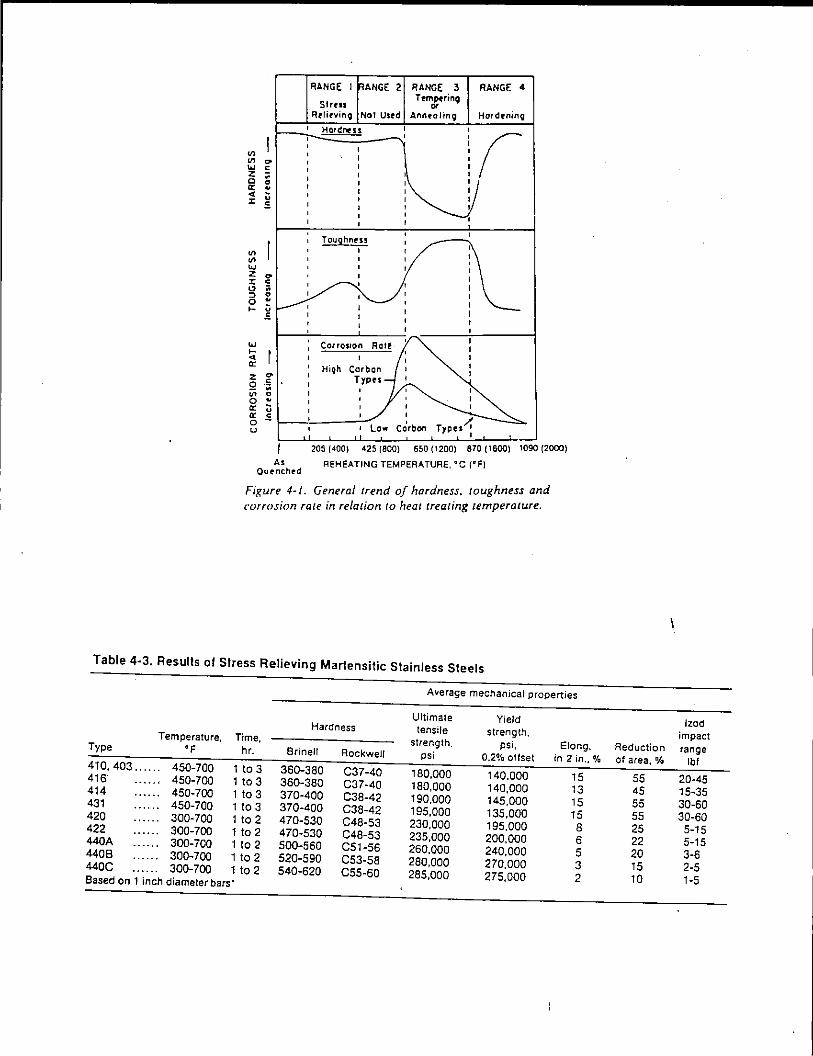
Fixure 4-1. General trend of hardness. /Oughness and corrosion rate in relation to heat treating temperature.
Table 4-3. Results ol Stress Relieving Martensitic Stainless Steels
Average mechanical properties
Ultimate Yield Hardness tensile strength, Temperature, Time, strength. psi, Elong. Type 'F hr. Sri nell Rockwell psi 0.2% offset in 2 in.,%
410. 403 ...... 450-700 1 to 3 360-380 C37-40 180.000 140.000 15 416" 450-700 1 to 3 360-380 C37-40 180.000 140,000 13 414 450-700 1 to 3 370-400 C38-42 190.000 145.000 15 431 450-700 1 to 3 370-400 C38-42 195.000 135.000 15 420 300-700 1 to 2 470-530 C48-53 230.000 195.000 8 422 300-700 1 to 2 470-530 C48-53 235.000 200.000 6 440A 300-700 1 to 2 500-560 C51-56 260.000 240.000 5 4408 300-700 1 to 2 520-590 C53-58 280,000 270,000 3 440C 300-700 1 to 2 540-620 C55-60 285,000 275,000 2 Based on 1 inch diameter bars·
lz:od impact
Reduction range of area,% lbf
55 20-45 45 15-35 55 30-60 55 30-60 25 5-15 22 5-15 20 3-6 15 2-5 10 1-5
~
.,...--rl200 ~ z ~
1----'--liOO 111
" 0
<40 c:i ~
\.J------1 20 ;
AEH!:ATING TEMPERATURE, oc (°F)
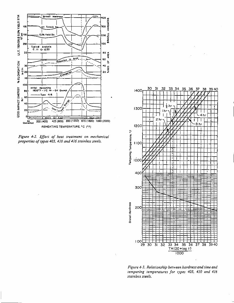
Figure 4-2. Effect of heat treatment on mechanical properties of types 403, 410 and 416 stainless steels.
u. . ~ "@
140
130
120
0
0
0
:1. 110 E
0
• >~ 0 ·o • E tooo ~
. • •
400
300
-E 200 • l:
• -= a;
100
30 31 32 33 34 35 36 37 38 3940 I I /
I II
4 hr I II I/
I hr 1 1t:11 I I I I) '-4hr r+-I
2 ~r I\ r\ 8
1 h~ I 1"-) ",{
I 'Y I/ I I I I I /I I
' I r/ I I
'/ I I I '/I [/ I I I I
r; / i I I I "II / ,I I I i
I ! I I
" . • . . • .
. ' : f++ -
"" H-
-
' I ' I . -29 30 31 32 33 34 35 3o 37 38 3940
Tx(20+1og tl
1000
Figure 4-3. Relationship between hardness and time and tempering temperatures for types 403, 410 and 416 stainless steels.
,), I Tolol Tests~ 3281
-- -- '·'"~! of Hl9he$1 V l ____ ... ------- Clues -------·- --1~.
--0 ~ ! "•
1/0
roo
90
8
;g I ,. 7 0 \I --~ " a:
w \ ' ,, ~\
"" ~ 60
\
I \
0 ' " ' '
1-
~ ;!
5
c ' 0 4 !:!
0 -I
'1'--.li'JJ. ' rt Of ........ l.o ............ ""e~, V.
0 .... ..,. OIIJe
I -- ' --2
Type 403 Ternfldled --0 --
Bri~ell 21~12"'\
0 4 2 ' 5
OIAMioTEA OF BAR. INCHES
6
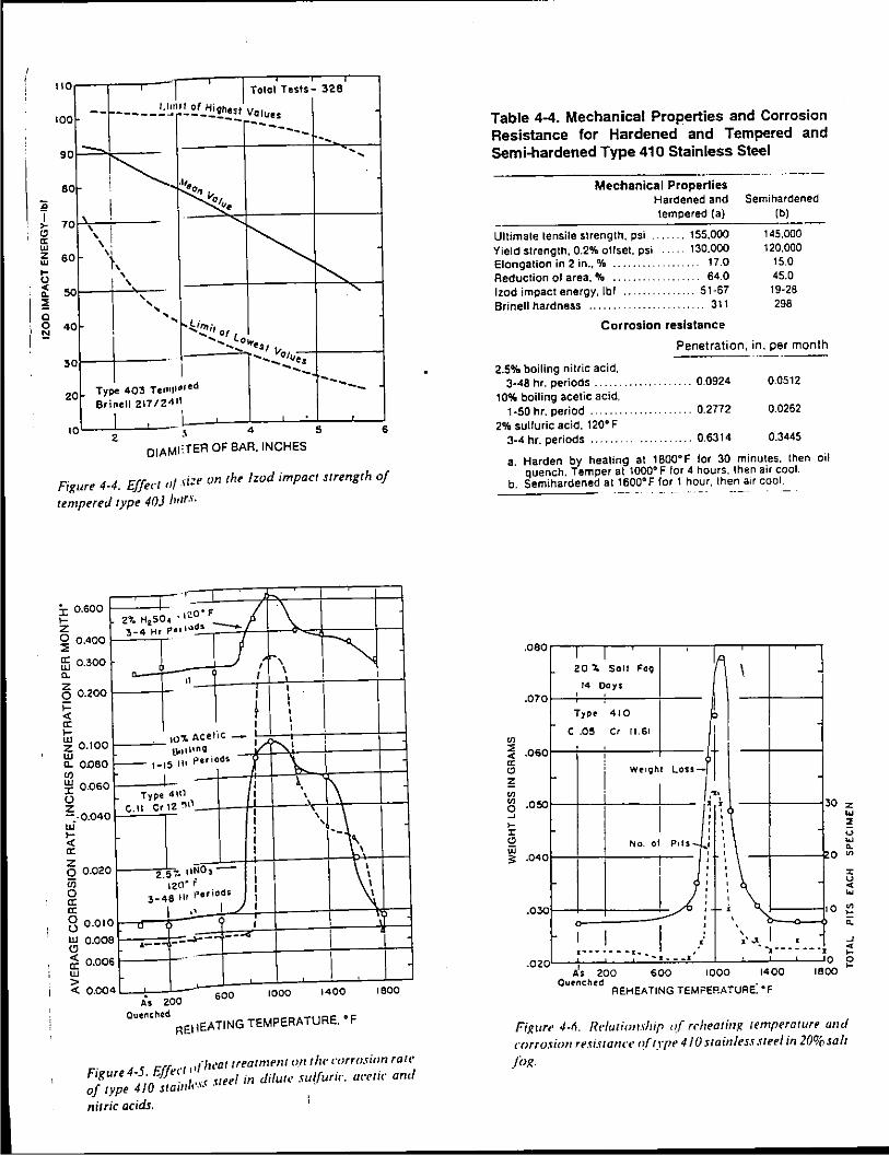
Figure 4·4. Effect o/ .>i:e on the !zod impact strength of
tempered type 40) Jr,rrs.
I o.soo .... z ~ 0.400
ffi 0.300 0. z 0 0.200 ;::: <( 0: l;j z 0.100 w 0. O.OBO
"' ~ 0.060 () z -.o.04 ui ~ 0:
0
-r
\ 2% H2S04 -l~o· F ./ 3-4 Hr P•• loldi -._
J ( f-, I'-"
I \ I
I I
I • • . ! I
I ul'J. ACetiC -
~· ' U•••\lnQ !/ ;--- 1-15 lit periods 1 \,_
I I, 1\ Type 4Hl II \ C. II Cr 12 "lll ',!_-\,
z 0 0.02 iii 0 0: 0:
0 2.57· nNO,-
~ 120" f
3_
48 111 rer iods
I 0 8 0.01
~ 0.00
C2 0.00 w
8
6
> <( 0.00 4
,, --o
' ----- --·-- I .. - I
0 1400 1600 . As 200 600 100
Quenched REi! EATING TEMPERATURE. 'F
. 5
E'" . t'lu•attreatmt'nl o.ntht• corrosion rart• Frgure 4· . ..JJec ''' · · 1
410 · 1 ·~~ ~reel in dilute• sul{unc acettc anc
of type stalll 1 • • • •
nitric acids.
Table 4-4. Mechanical Properties and Corrosion Resistance for Hardened and Tempered and Semi-hardened Type 410 Stainless Steel
Mechanical Properties Hardened and tempered (a)
Ultimate tensile strength, psi Yield strength, 0.2% offset. psi Elongation in 2 in., % ..... . Reduction of area. o/a •••••.•. lzod impact energy, lbf ..... . Brinell hardness
.... 155,000 130.000
17.0 64.0
.. ... 51·67 311
Corrosion resistance
Semi hardened (b)
145.000 120.000
15.0 45.0
19·26 298
Penetration. in. per month
2.5% boiling nitric acid, 3-48 hr. periods
10% boiling acetic acid, 1·50 hr. period .......
2% sulluric acid. 120" F 3-4 hr. periods ...... .
" 0.0924 0.0512
"' 0.2772 0.0262
0.6314 0.3445
a. Harden by heating at 1 BOO" F lor 30 minutes. then oil quench. Temper at 1000" F lor 4 hours. then air cool.
b. Semihardened at 1600" F for 1 hour, then a1r cool.
.08 0
.07
"' ~ .OS
13 ;; "'
0
0
I I lA 20 '- Salt Fo9 I
14 Days ' Type 410
c .05 c' II 61 I
! Lou-t
i We•oht
,, I I
~ .050 ~
5:
.. ~ . ' ' ' '
30 z
"' 2
" w ;:: .04 0
.030
.02
' No. ol P•ls ... ' ' '
l ' '
J! ' ' I I :
' '
.\ ' ' ' ·"'~
I . •
I
u
"' 0. 0 ~
" :;;! "' 0 ~ t: 0.
I . • ··------·-- -.-------. ~ .. 1--.I-- -J
I As 200 600 1000 1400 Ournchtd
REHEATING TEMPERATURE: •F
0 g 1800
Figure 4-fl. Relationship r~( rrheating temperature unci corrosion resi.uann· t~{ type 41 U stainless steel in 20% salt
/i>l(.
200 ,---,------,--~--,-~--r---,--r----,
,--I~ HCL. IZO"F I
1---'---1-~3 I Hr Ptuods l
100 ---+---aJ LlttO , - ~ -:__~ ~->- 0 I I ~ ~ ""o
1· - .
z~ ~-o ... -. ·•·. . • ~§tl40 _JI .... \ ... I --·~-~.'1\__t,__ .... a: ~ 1 65 't HN03 • 801hn9 ', ,· a:=)•O . ' I •. 0 ~ 1 .J 1 3 • 48 Hr PttlndS • ,• u .,. I I '· . w!l Typr 410 ·-. 1 •• '
~ ~ UZO C .II Cr 12 ~0 a: ·l w '· ;; OIOL_~_jl__L~~_L~~~~~~~
AI 200 600 1000 1400 1800
Quenched
REHEATING TEMPERATURE. "F
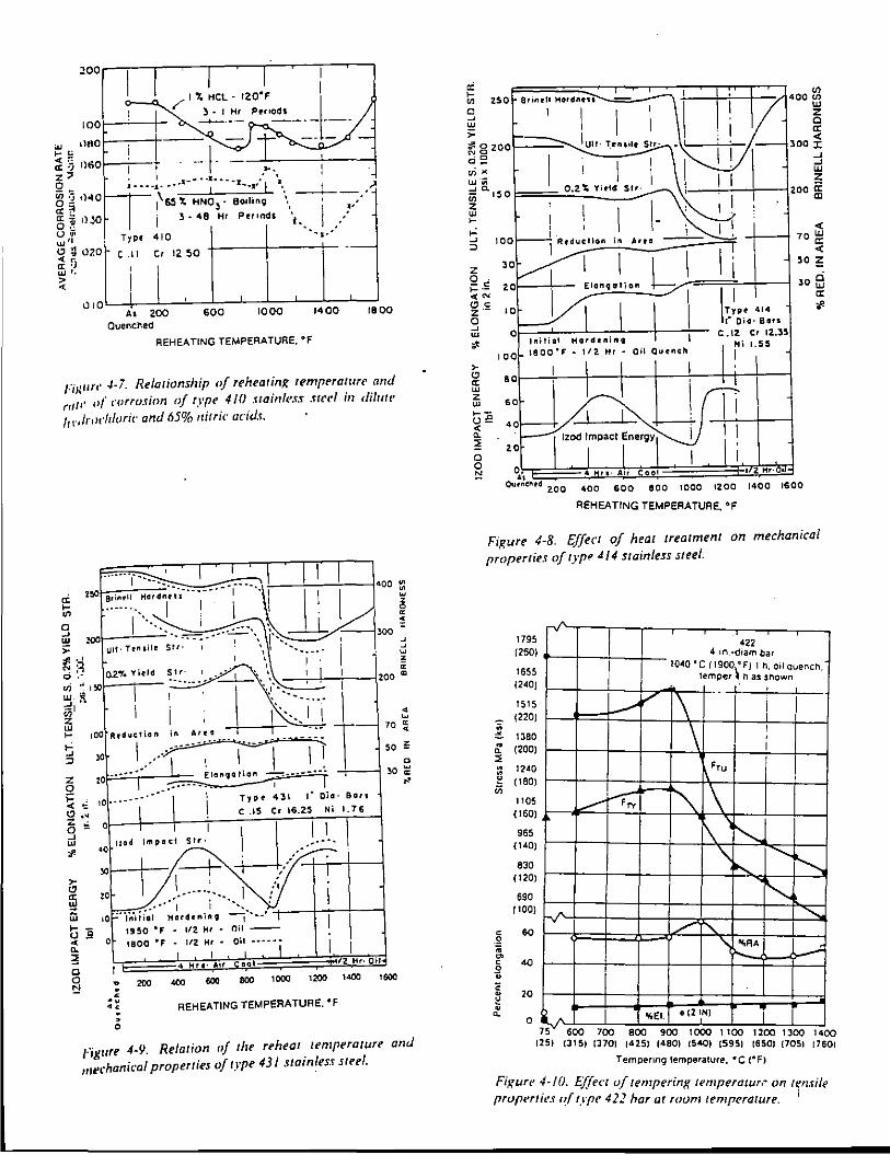
FiJ:IIt't' .J.-7. Relationship of rehear in~ rempnawrr and ,,,. o( corroJion of type 4/0 .uainh•ss stet'~ in difutf'
hr 11rorldoriC' and 65% nitric acids.
ci 'Z:C ... 400 t::
~
z 0
" • ~
'3 I ~ :oo~--'---' 300 =
J J ~ > Ull· Tensile z
" ~ ~~ ~ '- 0.2're Yield ~~r 1 _ •• -· 1 • ',\ __1_i 1
~/"' \ : -----· -\ ·-.:;~-+tl --i 200 (II
g I ·· ..• I 1 ~ tOO AeCIIIttion tn Aret •••
~ >0 ____ !_ ..... ~ :Z ZO. ~ Elor~qt!IOII ~ ~ o ==-------• I ~ ~ tO·------····· \ Type 431 t" Qia· Bort
~ ·~ 0 "'' lmpo•l '"'i Llc
1
.15 Cr 16.25 ~i 1.76
';/! 40 -----·
. _L_.~· ··~II G I
I , : . , . .------:.__ I ;'i
ffi 1.i ~----------1 i ·-•• : I' I I tor lntt1al Hard•nin<;t --j"·h• 1 ... -u .e -< 0 .. ::!
1950 •f • liZ Hr • Oil --
1800 •f • liZ Hr • Oil •••••• I
4 Hit•ltt "' IZ_ Hr· Oil
• ~ 70 ~
50 ~ a
30 ~
"
0
g 200 """ 600 BOO 1000 1200 1.000 1600 . < .. •• • 0
REHEATING TEMPERATURE. "F
figure 4-9. Relation of the rt>htat temperature and mechanical properties of type 431 stainless steel.
a: ~ ~ Cl) 250 Brinrll Harclftt-U - 400 Cl')
~ 1 I I ~ ,_ I < # o 200 Ult· 300 l:
d g I . I _, ~~ I I ~ : o.
150 0.2~ Yirtcl Sir· ZOO«:
~ ' m z w >- I ,_; 5 100 I. oninArto
i"'1j-L I 'I I I
< 70 w
~ z o. ~-= <'"' ClC z·o ~ w ,_
>-"' a: w z w ~-u£ <1: ~ 0
2
<00
Elonqotion /1 ~~ 414
.- Typ.t "'" ,~ O•o·
5
Oil Quench
IZ Ct 12.3 c. 1.55
50 !:
30 fa a: i'
aol ! I I I I I i ! I 60
o~ 4 Hfl· AiFCOot -Vt~Oi Oll:~c:llrd 2.00 400 600 SOO 1000 IZOO 1400 1600
REHEATING TEMPERATURE. "F
Figure 4-8. Effect of heat treatment on mechanical properties oftypl! d/4 stainless steel.
~ • a. ::; " " ~ in
179 (260
165 (240
151: (220
138 (200
12d
(180
110 (160
965 (140
830 (120
690 (100
c 60 2 ;;;
"' § 40
• c ~ 20
• a. 0
422 4 tn.-dtam bar
I 1040 • C (1900\ F) I h, oil Quench.
temper has shown __ __(
' -v Li I \ I
' I ' F,u
....---f--F;, "" 1\ \ "'-.
'\ ....... ~ "' !'----
r.; ........ L I"'\.
' ... AA ~
ij_ ~~~tEl. o 12 IN)
75" 600 100 aoo goo toco 1100 1200 13oo 1400 125) 13151 13701 14251 1480) !5401 !5951 !6501 (705! (760!
Tempettng lemperature. "C f"F)
Fixun• 4-/0. Elfe,·t of tempering temperatuN" on ltjn.rile prupertie.f r?(type 422 har at rovm temperature. 1
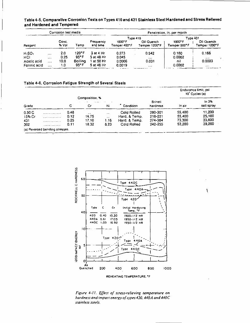
Table4-5. Comparative Corrosion Tests on Types 410 and 431 Stainless Steel Hardened and Stress Relieved and Hardened and Tempered
------Corrosion test media Penetration, in. per month
Type 410 Type 431 Cone. Frequency 1800'F Oil Quench 1900'F I Oil Quench
Reagent %Vol Temp and lime Temper 4QQ•F Temper 1200•F Temper sao• F Temper 1200°F --------··
H:SO, 2.0 120'F 3 at 4 Hr 0.273 0.542 HCt 0.25 95'F 5 at48 Hr 0.045 Acetic acid 10.0 Boiling 1 at 50 Hr 0.0006 0.031 Formic acid 1.0 95'F 5 at48 Hr 0.0019
·-- ------ ...
Table 4-6. Corrosion Fatigue Strength of Several Steels
Grade
o.soc 15% Cr 431 302
c 0.48 0.12 0.25 0.11
(al Reversed bending stresses.
"' "'
Composition, %
Cr
1~.75 17.10 18.32
Ni
1.16 8.23
Sri nell • Condition hardness
Cold Rolled 280·301 Hard. & Temp. 218-221 Hard. & Temp. 274-384
Cold Rolled 242-255
-----
I 60f---~o::!::--l---+---+-l---l-----l ~ ___ I Type 440~
...J - 1'-....... l 1 _.....-~ ------- ~- ....._ Typt 440A~ \
g 50- --IP~~.--:~~ -:-:-! ---...~~
>
" a; w z w
40
Type c
420 0.40 13.30 440A 0.61 17.03 440C 1.03 16.92
' ln1ti0l Hardenmq
Temp. "F -f-----\ 1900-1/2 HR 1950-1/2 HR 1950-1/2 HR
10-- ---t-- I Typt420-;" 1"·~ ... ,
.' Typt 440A -._ ;
s ,__ - I .... ·-;J: .....:: - ,--!. ...::::-+- .. --·> __ .-- ./ 1 Type 440C ----
.. ·-- I / ' I F=-~-:::_....:::..J_I___..__ji-__,__J,:::::::=j
Of-" As
Outnchtd 200 400 600 800 1000
REHEATING TEMPERATURE. "F
Figure 4-11. Effect of stress-relieving temperature on hardness and impacr energy o(rypes 420. 440A and 440C stainless sttel.s.
0.160 0.168 0.0002
nil 0.0003 0.0002
--------
Endurance limit. psi 10' Cycles (a)
ln3% In air salt spray
55.400 11,200 55,400 25,100 73,300 33,600 53,200 39,200
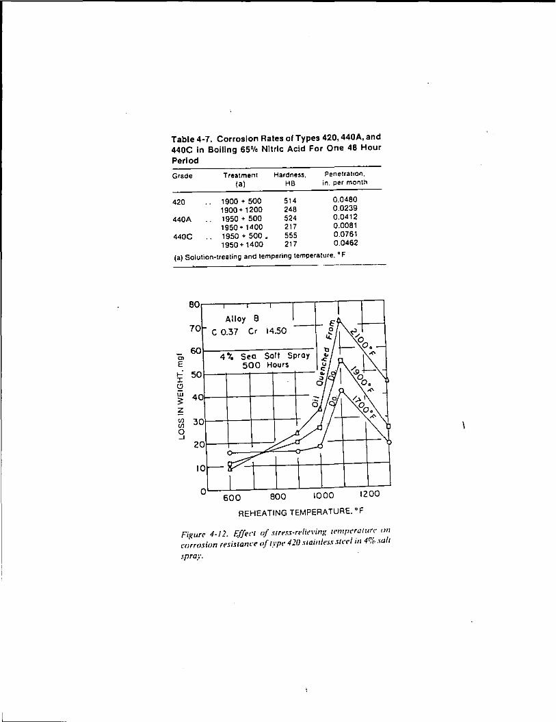
Table 4-7. Corrosion Rates of Types 420, 440A, and 440C In Boiling 65% Nitric Acid For One 48 Hour Period
Grade Treatment Hardness. PenetratiOn,
(a) HB in. per month
420 1900 + 500 514 0.0480 1900+ 1200 248 0.0239
440A 1950 + 500 524 0.0412 1950+ 1400 217 0.0081
440C 1950 + 500- 555 0.0761 1950 + 1400 217 0.0462
(a) Solution-treating and tempering temperature. a F
"' E
70 Alloy B
C 0.37 Cr
ro~~----------4% Sea Salt Spray 500 Hours
,.: 50 1-----.----..----t---+--I (!)
w :;; z 401~-4--~--~--~
~ 30~~~~~-1--+ 0 -'
·-·-----
oL--6~0-0-~-BOLO_J__IO~O-O_L-_1~2~00~
REHEATING TEMPERATURE. "F
FiKurr 4-12. Effect of stres:r-reli<•\•inx wm[H'ratun· tm corrosion resistance of typt• 420 .uainle.u .'itt'el in 4% .'ialt
spray.
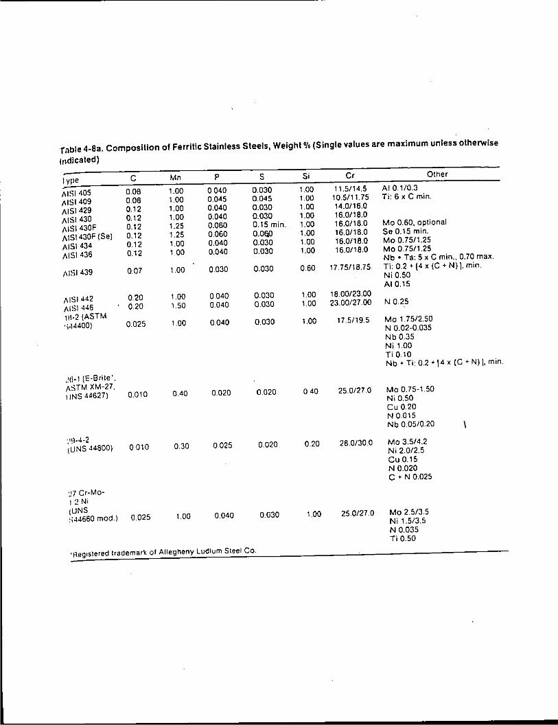
·rnble 4-Sa. Composition of Ferrilic Stainless Steels, Weight 'lo (Single values are maximum unless otherwise
indicated)
lype c Mn p s Si Cr Other
A lSI 405 0.08 1.00 0040 0.030 1.00 11.5/14.5 AI 0.1/0.3
A lSI 409 0.08 1.00 0.045 0.045 1.00 10.5/11.75 Ti: 6 x C min.
AISI429 0.12 1.00 0.040 0.030 1.00 14.0/16.0
AJSI 430 0.12 1.00 0.040 0.030 1.00 16.0/18.0
AJSI 430F 0.12 1.25 0.060 0.15 min. 1.00 16.0118.0 Mo 0.60. optional
AiSI430F (Se) 0.12 1.25 0.060 0.0!;0 1.00 16.0/18.0 Se 0.15 min.
A lSI 434 0.12 1.00 0.040 0.030 1.00 16.0/18.0 Mo 0.75/1.25
A lSI 436 0.12 1.00 0.040 0.030 1.00 16.0/18.0 Mo 0.75/1.25 Nb + Ta: 5 x C min .. 0.70 max.
A lSI 439 007 1.00 0.030 0.030 0.60 17.75/18.75 Ti: 0.2 + [4 x (C + N) ], min. Ni 0.50 AI 0.15
A lSI 442 0.20 1.00 0 040 0.030 1.00 18.00/23.00
AISI 446 0.20 1.50 0.040 0.030 1.00 23.00/27.00 N 0.25
111-2 (ASTM •;.\4400) 0.025 1.00 0.040 0.030 1.00 17.5/19.5 Mo 1 75/2.50
N 0.02-0.035 Nb 0.35 Ni 1.00 Ti 0.10 Nb + Ti: 0.2 + [ 4 x (C • N) ]. min .
. !6-1 (E-Brite'. ASTM XM-27. tiNS 44627) 0.010 0.40 0020 0 020 0 40 25.0/27 0 Mo 0.75-1.50
Ni 0.50 Cu 0.20 N0.015 Nb 0.05/0.20
; 19-4-2 1UNS 44800) 0.010 0.30 0.025 0.020 0.20 28.0/30 0 Mo 3.5/4.2
Ni 2.0/2.5 Cu 0.15 N 0.020 C • N 0.025
":.7 Cr-Mo-1.2 Ni tUNS :io\4660 mod.) 0.025 1.00 0.040 0.030 1.00 25.0/27.0 Mo 2.5/3.5
Ni 1.5/3.5 N 0.035 Ti 0.50
'Reg•stered trademark of Allegheny Ludlum Steel Co.
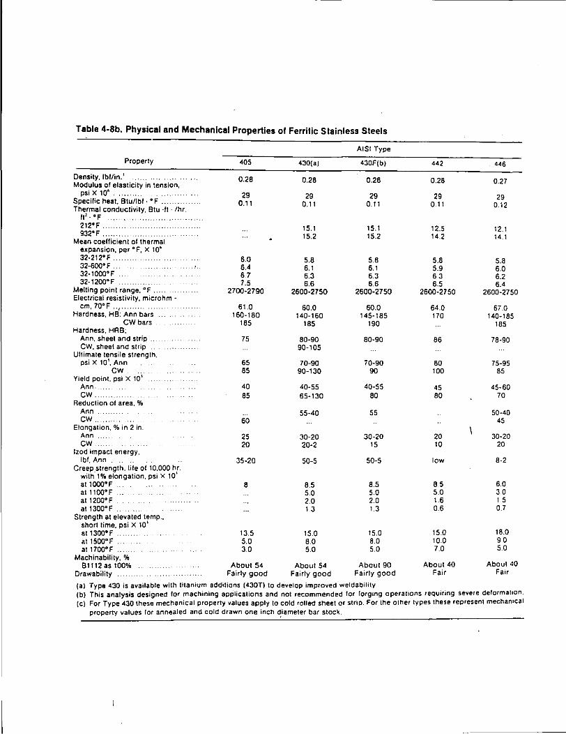
Table 4-Sb. Physical and Mechanical Properties ol Ferritic Slainless Steels
AISI Type
Property 405 430(a) 430F(bl 442 446
Density, lbflin. 1
Modulus of elasticity in tension, 0.28 0.28 0.28 0.28 0.27
psiXlO~ ...... 29 29 29 29 29 Specific heat. Btu/lbl . • F . 0.11 0.11 0.11 0.11 0. i2 Thermal conductivity, Btu ·fl · /hr.
fl: . oF 212°F .. 15.1 15.1 12.5 12.1 932°F 15.2 15.2 14.2 14.1
Mean coefficient of thermal expansion, per °F, X tO& 32·212•F. 6.0 5.8 5.8 5.8 5.8 32-600° F .. . .'. 6.4 6.1 6.1 5.9 6.0 32-1000°F 6.7 6.3 6.3 6.3 6.2 32·1200•F 7.5 6.6 6.6 6.5 6.4
Melting point range, • F . 2700·2790 2600-2750 2600-2750 2600-2750 2600·2750 Electrical resistivity, microhm-
em, 70°F .. 1 .... 61.0 60.0 60.0 64.0 67.0 Hardness, HB: Ann bars 160·180 140-160 145·185 170 140-185
CW bars 185 185 190 185 Hardness. HAB;
Ann, sheet and strip . 75 80-90 80·90 86 78·90 CW, sheet and strip 90-105
Ultimate tensile strength. psi X 10'. Ann 65 70-90 70-90 80 75-95
cw 85 90-130 90 100 85 Yield point, psi X 101
Ann. 40 40-55 40-55 45 45-60 CW. 85 65-130 80 80 70
Reduction of area, % Ann 55-40 55 50-40 cw. 60 45
Elongation,% in 2 in. Ann 25 30-20 30-20 20 30-20 CW. 20 20-2 15 10 20
tzod impact energy, lbf, Ann 35·20 50-5 50-5 low 8-2
Creep_strength. life of 10.000 hr. with 1% elongation. psi X 10' at 1000°F . 8 8.5 8.5 8.5 6.0 at 11QQ°F so 5.0 5.0 3.0 at1200°F 2.0 2.0 1.6 1 5 at1300°F 13 1.3 0.6 0.7
Strength at elevated temp., short lime. psi X 10' at 1300°F 13.5 15.0 15.0 15.0 18.0 at 1500°F 5.0 8.0 8.0 10.0 90 at 17QQ°F 3.0 5.0 5.0 7.0 5.0
Machinability. % 91112 as 100% About 54 About 54 About 90 About 40 About 40
Drawability Fairly good Fairly good Fairly good Fair Fair
(a) Type 430 is available with titanium additions {430T) to develop improved weldability (b) This analysis designed for machining apPlications and not recommended lor rorg~ng operalions requiring severe delorma110n. (c) For Type 430 these mechanical property values apply to cold rolled sheet or strip. For the other types these represent mechamcal
property values lor annealed and cold drawn one inch d,iameler bar stock.
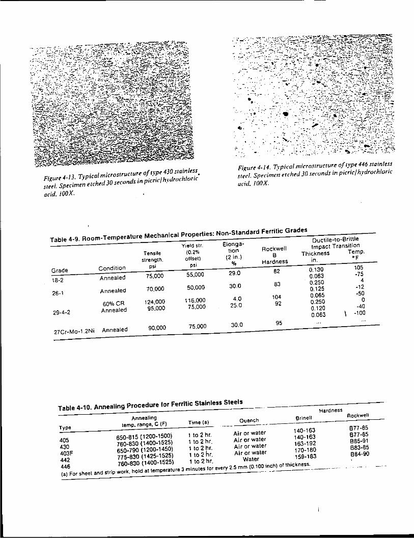
Figure 4-/3. Typical microstructure of typ• 430 stainless. steeL Specimen ezchecl 30 seronds in pil·rid hyclrodzloric
acid. JOOX.
, .. _.;-.-
. --_-· _ _.;-' :,~-·
.. -- .... .-
...
... :.--
• •· .-..
- ·--
-. -~ . -· ..
;:.:w ~. ·. -·:~·
.~ .... -·_:-:· :: __ "..:~--- -~--··, . :- ·. :··.
Figure 4-14. Typical microstructure of type 446 stainless stef'i. Spt'cimt•n t'tched 30 seconds in picric/ hydrochloric
acicl. IOOX.
Table 4-9. Room-Temperature Mechanical Properties: Non-Standard Ferri tic Grades
Elonga-Oucti le-to-8 rittle
Yield sir.
Tensile (0.2% tion Rockwell Impact Transition
strength. otlset) (2 in.) B Thickness Temp.
Grade Condition psi P" % Hardness in. "F
18-2 Annealed 75,000 55,000 29.0 62 0.130 105
0.063 -75
26-1 Annealed 70,000 50.000 30.0 63 0.250 4
0.125 -12
60%CR 124,000 116.000 4.0 104 0.065 -50
29·4-2 Annealed 95,000 75.000 25.0 92 0.250 0 0.120 -40
0.063 -100
27Cr·Mo-1.2Ni Annealed 90,000 75.000 30.0 95
Table 4-10. Annealing Procedure for Ferrllic Stainless Steels Hardness
Annealing
Type lemp, range, C (F) Time (a) Quench Brine\1 Rockwell
-----------
405 650-815 (1200-1500) 1 to 2 hr. Air or water 140-163 877-85
430 760-830 (1400-1525) 1to2hr. Air or water 140-163 877-85
403F 650-790 (1200-1450) 1to2hr. Air or water 163-192 885-91
442 775-830 (1425-1525) 1 to 2 hr. Air or water 170-180 883-85
446 760-830 (1400-1525) 1 to 2 hr. Water 159-183 884-90
(a) For sheet and sHip work, hold at temperature 3 minutes for every 2.5 mm (0.100 inch) of thickness.
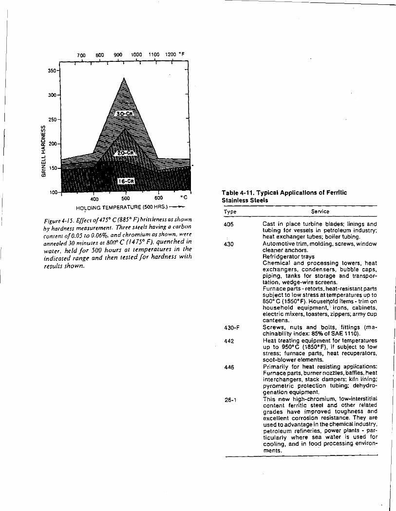
en en w z c a: ~ -' -' w z a: C!l
700 BOO 900 1000 1100 1200 'F
400 500
HO~D\NG TEMPERATURE (500 HAS.)-
Figure 4-15. Effect of 475' C (885' F)hrittleness as slwwn h~· hardness measurement. Three suets having a carbon c~nlE'nl of0.05 ro 0.06%. and chromium as shown. were annealed 30 minutt.< at 800' C (1475° F). quenched in water. held for 500 hours at umperatures in the indicated range and then rested for hardness wtth results shown.
Table 4-11. Typical Applicalions of Ferrlllc Stainless Steels
Type
405
430
430-F
442
446
26-1
Service
Cast in place turbine blades: linings and tubing for vessels in petroleum industry: heat exchanger tubes: boiler tubing. Automotive trim, molding. screws, window cleaner anchors. Refri dgerator trays Chemical and processing towers, heat exchangers, condensers, bubble caps, piping, tanks for storage and transportation, wedge-wire screens. Furnace parts- retorts. heat-resistant parts subject to low stress at temperatures up to 850' C (1550'F). Houset\old items- trim on household equipment,·. irons, cabinets, electric mixers, toasters, zippers; army cup canteens. Screws, nuts and bolts, fittings (machinability index: 85% of SAE t 1 10). Heat treating equipment for temperatures up to 950' C (1850' F), if subject to low stress: furnace parts, heat recuperators, soot-blower elements. Primarily for heat resisting applications: Furnace parts, burner nozzles, baffles. heat interchangers. stack dampers: kiln lining: pyrometric protection tubing: dehydrogenation equipment. This new high-chromium, low-interstitial content ferritic steel and other related grades have improved toughness and excellent corrosion resistance. They are used to advantage in the chemical industry, petroleum refineries, power plants - particularly where sea water is used for cooling, and in food processing environments.
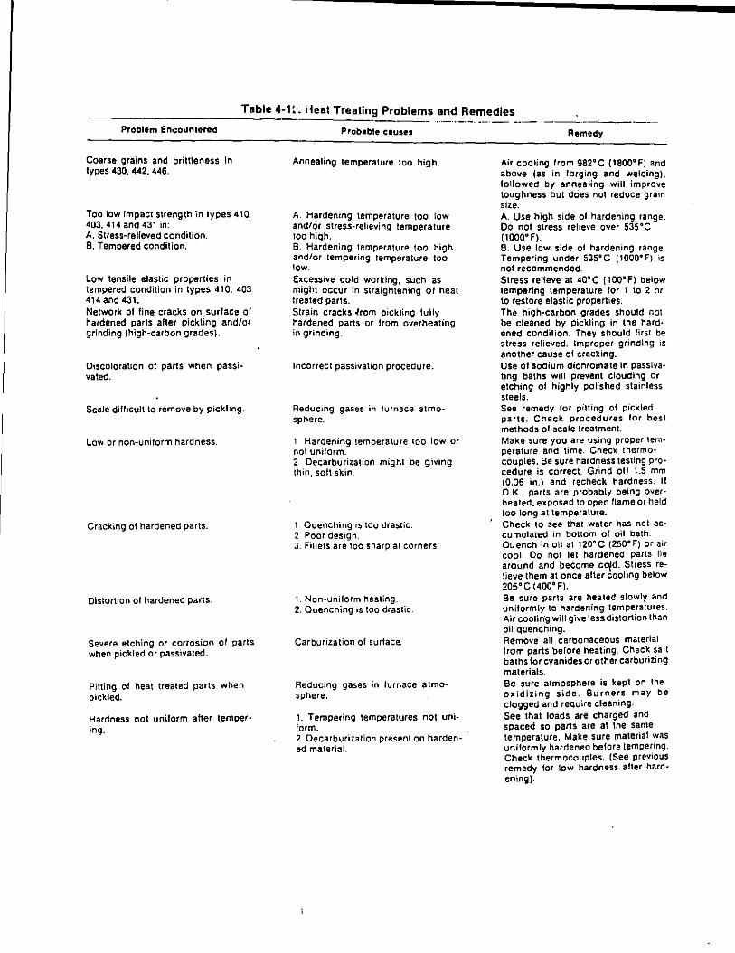
___________ T_a_b_l_e_4_-_1:_·_._H_e:_a_I:_T_:_•_:_ea:::t:::in:_:g Problem_:; _a~~~~~e_dl_es __ ---·--------Problem Encounlered
Coarse grains and brittleness in types 430. 442. 446.
Too low impact strength in types 410. 403,414 and 431 in: A. Stress-relieved condition. B. Tempered condition.
Low tensile elastic properties in tempered condition in types 410. 403 414 and 431. Network of fine cracks on surface of hardened parts alter pickling and/or grinding (high-carbon grades).
Discoloration of parts when passivated.
Scale difficult to remove by pickling.
Low or non-uniform hardness.
Cracking of hardened parts.
Distortion of hardened parts.
Severe etching or corrosion of parts when pickled or passivated.
Pitting of heat treated parts when pickled.
Hardness not uniform aher tempering.
Probable causes
Annealing temperature too high.
A. Hardening temperature too low and/or stress-relieving temperature too high. B. Hardening temperature too high and/or tempering temperature too low. Excessive cold working, such as might occur in straightening of heat treated parts. Strain cracks ~rom pickling tully hardened parts or from overheating in grinding.
Incorrect passivation procedure.
Reducing gases in furnace atmosphere.
1 Hardening temperature too low or not uniform. 2. Decarburization might be giving thin, soft skin.
1 Quenching rs too draslic. 2 Poor design. 3. Fillets are too sharp at corners
1. Non-unilorm heating. 2. Quenching is too drastic.
Carburization of surface.
Reducing gases in furnace atmosphere.
1. Tempering temperatures not uniform. 2. Decarburization present on hardened material.
Remedy
Air cooling from 982°C {1800°F) and above (as in forging and welding). followed by annealing .will improve toughness but does not reduce grain size. A. Use high side of hardening range. Do not stress relieve over 535°C (tOOO"F). B. Use low side of hardening range. Tempering under 535°C (1000°F) is not recommended. Stress relieve at 40°C p00°F) below tempering temperature for 1 to 2 hr. to restore elastic properties. The high-carbon grades should not be cleaned by pickling in the hardened condition. They should first be stress relieved. Improper grinding is another cause of cracking. Use of sodium dichromate in passivating baths will prevent clouding or etching of highly polished stainless steels. See remedy lor pitting of pickled parts. Check procedures lor best methods of scale treatment. Make sure you are using proper temperature and time. Check thermocouples. Be sure hardness testing procedure is correct. Grind oil 1.5 mm (0.06 in.) and recheck hardness. II O.K .. parts are probably being over· healed, exposed to open !tame or held too long at temperature. Check to see that water has not accumulated in bottom of oil bath Quench in oil at 120"C (250"F) or air cool. Do not let hardened parts lie around and become c~d. ~tress relieve them at once alter cooling below 205"C (400"F). Be sure parts are heated slowly and uniformly to hardening temperatures. Air coolin·g will give tess distortion than oil quenching. Remove all carbonaceous material from parts before heating. Check salt baths lor cyanides or other carburizing materials. Be sure atmosphere is kept on the oxidizing side. Burners may be clogged and require cleaning. See that loads are charged and spaced so parts are at the same temperature. Make sure material was uniformly hardened before tempering. Check thermocouples. (See previous remedy for tow hardness alter hardening).
L__
Cr
'' ' Fe ' " 10 ( }( v )( '' ){ )( }( v }( }( - y )( y '' y ){ ' Ni
%Nickel--~ Figure 5-J. Jron-chromium-nickelternary diagram for the cast heat resistant alloys. In addition to the three elements shown, these alloys contain small amounts of copper, manganese, silicon, phosphorus and sulfur.
-
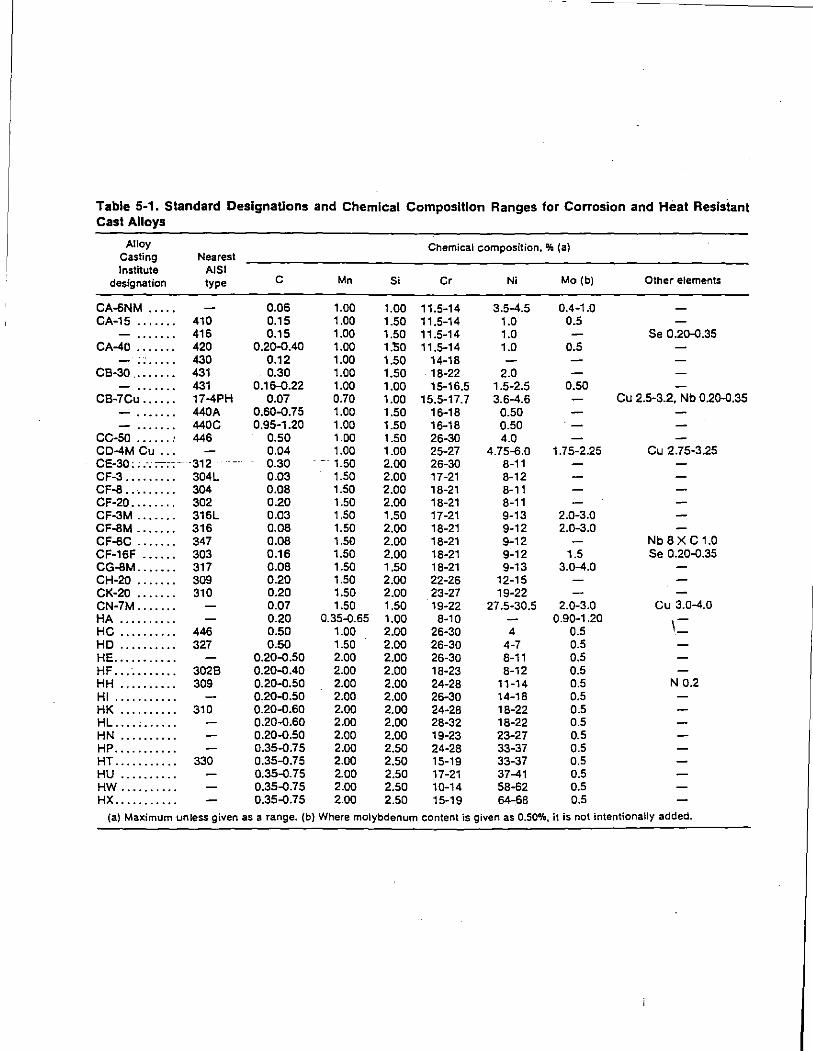
Table 5-1. Standard Designations and Chemical Composition Ranges for Corrosion and Heat Resistant Cast Alloys
Alloy Chemical composition. OJa (a) Casting Nearest Institute AJSI
designation type c Mn Si Cr Ni Mo (b) Other elements
CA-6NM ..... 0.06 1.00 1.00 11.5-14 3.5-4.5 0.4-1 .o CA-15 ....... 410 0.15 1.00 1.50 11.5-14 1.0 0.5
416 0.15 1.00 1.50 11.5-14 1.0 Se 0.20-<l.35 CA-40 ....... 420 0.20-<l.40 1.00 1.50 11.5-14 1.0 0.5
430 0.12 1.00 1.50 14-18 CB-30 ........ 431 0.30 1.00 1.50 18-22 2.0
431 0.16-<l.22 1.00 1.00 15-16.5 1.5-2.5 0.50 CB-7Cu ...... 17-4PH O.Q7 0.70 1.00 15.5-17.7 3.6-4.6 Cu 2.5-3.2. Nb 0.20-<>.35
440A 0.60-<l.75 1.00 1.50 16-18 0.50 440C 0.95-1.20 1.00 1.50 16-18 0.50
CC-50 ...... : 446 0.50 1.00 1.50 26-30 4.0 CD-4M Cu ... 0.04 1.00 1.00 25-27 4.75-6.0 1.75-2.25 Cu 2.75-3.25 CE-30; .. -. :-:-;: ·-- ·312. 0.30 - -- 1.50 2.00 26-30 8-11 CF-3 ......... 304L 0.03 1.50 2.00 17-21 8-12 CF-8 ......... 304 0.08 1.50 2.00 18-21 8-11 CF-20 ........ 302 0.20 1.50 2.00 18-21 8-11 CF-3M ....... 316L 0.03 1.50 1.50 17-21 9-13 2.0-3.0 CF-8M ....... 316 0.08 1.50 2.00 18-21 9-12 2.0-3.0 CF-8C ....... 347 0.08 1.50 2.00 18-21 9-12 Nb8XC1.0 CF-16F ...... 303 0.16 1.50 2.00 18-21 9-12 1.5 Se 0.20-<l.35 CG-8M ....... 317 0.08 1.50 1.50 18-21 9-13 3.0-4.0 CH-20 ....... 309 0.20 1.50 2.00 22-26 12-15 CK-20 ....... 310 0.20 1.50 2.00 23-27 19-22 CN-7M ....... 0.07 1.50 1.50 19-22 27.5-30.5 2.0-3.0 Cu 3.0-4.0 HA .......... 0.20 0.35-<J.65 1.00 8-10 0.90-1.20 HC .......... 446 0.50 1.00 2.00 26-30 4 0.5 HD .......... 327 0.50 1.50 2.00 26-30 4-7 0.5 HE ........... 0.20-<J.50 2.00 2.00 26-30 8-11 0.5 HF ........... 3026 0.20-<l.40 2.00 2.00 18-23 8-12 0.5 HH .......... 309 0.20-<l.50 2.00 2.00 24-28 11-14 0.5 N 0.2 HI ........... 0.20-<l.SO 2.00 2.00 26-30 14-18 0.5 HK .......... 310 0.20-<l.60 2.00 2.00 24-28 18-22 0.5 HL .... , ...... 0.20-0.60 2.00 2.00 28-32 18-22 0.5 HN .......... 0.20-<l.50 2.00 2.00 19-23 23-27 0.5 HP ........... 0.35-<J.75 2.00 2.50 24-28 33-37 0.5 HT ........... 330 0.35-<J.75 2.00 2.50 15-19 33-37 0.5 HU .......... 0.35-<J.75 2.00 2.50 17-21 37-41 0.5 HW .......... 0.35-<J.75 2.00 2.50 10•14 58-62 0.5 HX ........... 0.35-<l.75 2.00 2.50 15-19 64-68 0.5
(a) Maximum unless given as a range. (b} Where molybdenum content is given as 0.50%, it is not intentionally added.
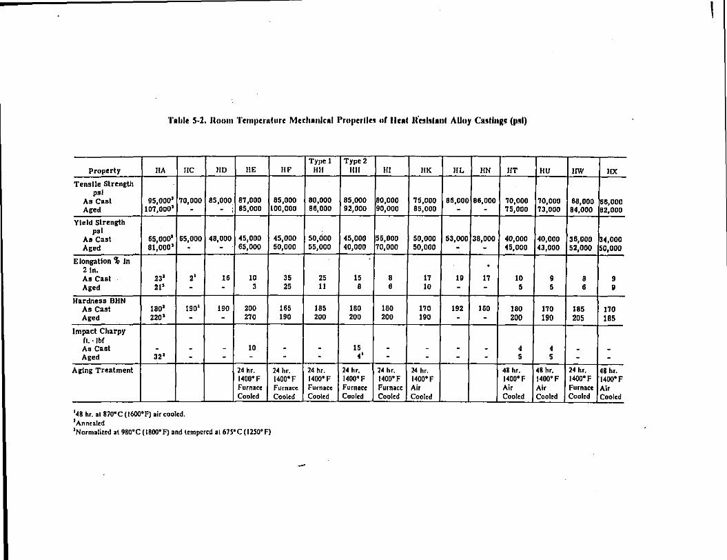
'l'ohle S-2. lloom 'l'emJscralurc Mechanical l'ruJ•crlle• of llfRI liHI•Ianl Alloy Ca•llugJ (Js•l)
Property IIA IIC
Tensile Strength psi
As Cast 95,0001 70,000 Aged 107,0003 -
Yield Strength psi
65,0001 As Cast 65,000 Aged 81,000' -
Elongation% In 21n. As Cast 23' 2' Aged 21' -
Hardness BHN As Cast lBO' 1901
Aged 220' -Impact Charpy
ft. · lbf As Cast - -Aged 32' -
Aging Treatment
148 hr. at no·c (1600°F) air cooled. 1Anncalcd
110 liE IIF
85,000. 87,000 85,000 - : 85,000 100,000
48,000. 45,000 45,000 - 65,000 50,000
16 10 35 - 3 25
190 200 165 - 270 190
- 10 -- - -24 hr. 24 hr. 1400°F 1400' F Furnace Furnace Cooled Cooled
1Normalized at 98o•c { 1800°F) and tempered al 67S•c (1250°F)
Type 1 Type 2 Ill! Jill Ill IlK IlL liN liT
80,000 85,000 80,000 75,000 86,000 88,000 70,000 88,000 92,000 90,000 85,000 - - 75,000
so,doo 45,000 55,000 50,000 53,000 38,000 40,000 55,000 40,000 70,000 50,000 - - 45,000
. 25 15 8 17 19 17 10 II 8 6 10 - - 5
185 180 180 170 192 160 180 200 200 200 190 - - 200
- 15 - - - - 4 - 4' - - - - 5
24 hr. 24 hr. 24 hr. 24 hr. 48 hr. 1400' F 1400' F 1400'F 1400'F 1400' F Furnace Furnace Furnace Air Air Cooled Cooled Cooled Cooled Cooled
I
IIU IIW !IX
70,000 60,000 66,000 73,000 84,000 82,000
40,000 36,000 34,000 43,000 52,000 50,000
9 8 9 5 6 9
170 185 170 190 205 185
4 - -5 - -
48 hr. 24 hr. 48 hr. 1400' F 1400' F 1400'F Air Furnace Air Cooled Cooled Cooled
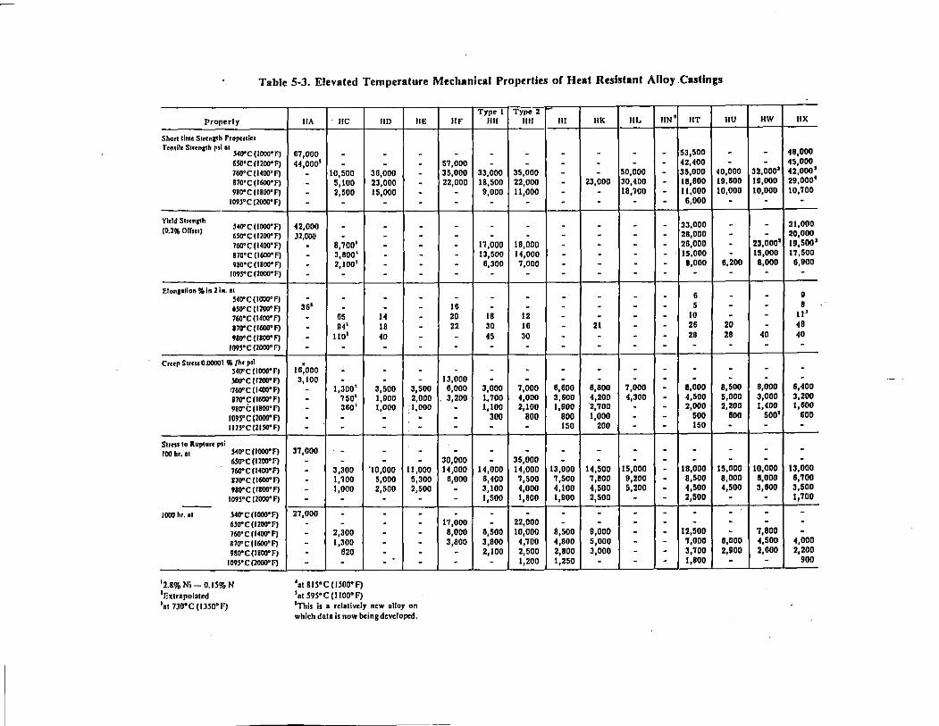
Table 5-3. Elevated Temperature Mechanical Properties of Heal Resistant Alloy .Castings
Properly
Shonlimt Strcna:th Propcnin Tcn1ilc Strength psi at
.S40"C(I000°F) 6WC(I2000F) 760°C(I400"F) 870" c ( 1600" F) 9IO"C(IIOO"F)
109l"CC2000"F)
Yield Strcna:th 540"C IIOOO"F) (O.l% orrm) UO" C (!lOG- F) 760" C ( 1400" F) 170"C IJGIWF) 9SO"C(IBooeF)
I09.5°C(2000•F)
Elon111lon %In lin. a1 !140"C (1000" F) UO"C(I200"F) 7605 C(I400"F) sro•ccr600•FJ 9Bo•c (1800" F)
1on•cuOOO"FJ
Crttr Sum 0.00001 91. /hr rsl !!41f'c uooo·n !!oo•c cnoo-F) :760"C(I400•F) 170"C(1600"F) 980"i:(IBOO"F)
109!1"C(1000"F) 111.5"C(21.50"F)
Sutss lo Rupture psi IOOhr. II !140"C (fOOD• F)
6SO"C (1200"F) 760"C(I400•F) 810"C (1600"f) 980"C (IIOO"F)
1095°C (2000"F) ---1000 hr. II S40"C(IOOO"F)
6.500C(I200"F) 760" c ( 1400" F) 110" c ( 1600" F) 9BD"C(IBOO"f)
I09S•C(2000"F)
12.8% Ni- O.IS% N 1Extrapolated 1at 730"C (IJSO"F)
IIA IIC
67,000 -44,0001 -- 10,500
- 5,100 - 2,500 - -
42,000 -)2,000 -- 8,700 1
- 3,800 1
- z,too' - -- -
36' -- 65 - 94' - 1101
- -to:ooo -3,100 -- 1,300 1
- 7501
- 360 1
- -- -37,000 -
- -- 3,300 - 1,700 - 1,000
- -27 ,ooo -
- -- 2,300 - 1,300
- 620 - -
•at BIS"C(HOD"F) 1nr59S"C (IIOO"F)
liD liE
- -- -36,000 -23,000 -15,000 -
- -- -- -- -- -- -- -
- -- -H -18 -40 -- -
- -- -
3,500 3,500 1,900 2,000 1,000 :t,ooo - . - -- -- -
'10,000 11,000 5,000 5,300 2,500 2,500 - . -- -- -- -- -- -- -
'This is a rclalivcly new alloy on which data is now bcinBdcvclopcd,
IfF
-57,000 35,000 22,000
--
-------
16 20 22 ---
13,000 6,000
. 3,200 ----
30,000 14,000
6,000 ---
17,000 8,000 3,800
--
Type 1 Type 2 1111 1111 Ill IlK IlL liN a liT IIU
- - - - - - 53,500 -- - - - - - 42,400 -
33,000 35,000 - - 50,000 - 35,000 40,000 18,500 22,000 - 23,000 30,400 - 18,800 19,600 9,000 11,000 - - 18,700 - 11,000 10,000
- - - - - - 6,000 -- - - - - - 33,000 -- - - - - - 28,000 -
11,000 18,000 - - - - 28,000 -13,500 14,000 - - - - 15,000 -
8,300 7,000 - - - - 8,000 8,200 - - - - - - - -
- - - - - - 6 -- - - - - - 5 -
18 12 - - - - 10 -30 16 - 21 - - 26 20 45 30 - - - - 28 28
- - - - - - - -
- - - - - - - -- - - - - - - -
3,000 7,000 6,600 8,800 7,000 - 8,000 8,500
·~ 700 4,000 3,600 4,200 4,300 - 4,500 5,000 1, too 2,100 1,900 2,700 - - 2,000 2,200
300 800 800 1,000 - - 500 BOO
- - 150 200 - - 150 -- - - - - - - -- 35,000 - - - - - -
H,ooo 14,000 13,000 14,500 15,000 - 18,000 15,000 6,400 7,500 7,500 7,800 9,200 - 8,500 8,000 3,100 4,000 4,100 4,500 5,200 - 4,500 4,500 1,500 1,800 1,900 2,500 - - 2,500 -- - - - - - - -- 22,000 - - - - - -
8,500 10,000 8,500 9,000 - - 12,500 -3,800 4,700 4,800 s,ooo - - '1,000 6,000 2,100 2,500 2,800 3.000 - - 3,700 2,900
- 1,200 1,250 -~--
- - 1,800 -
HW IIX
- 48,000 - 45,000 32,0001 42,000 1
19,000 29,0004
10,000 10,'1'00
- -- 21,000 - 20,000
23,0001 19,500' 15,000 1'1,500 8,000 6,900 - -
- • - 8 - II' - 48
40 40 - -
- -- -6,000 6,400 3,000 3,200 1,400 1,600
5001 600 - -- -- -
10,000 13,000 8,000 8,100 3,800 3,500 - 1,700
- -- -7,800 -4,500 4,000 2,800 2,200
- 900
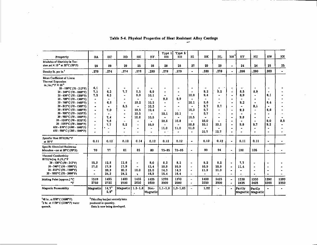
Property
Modulus of Eluticity in Ten· sion psi X 10"1 at lO"C (70"' f)
Density lb. per in. 1
Mnn Codricicnt of linear Thumal Expansion in.!in./"F X 10'1
20-IOO"CJ70-212"F) 20-S40"C(l0-IOOO"FI 20 -•so•c 110. 1200"FJ 20- 700"'C (70- IJOO"F) 20 . 760" c (70 • 1400" F) 20 • Bll" c 110 • 1 soo• FJ 20- 870"C (70 • 1600"F) 20 -IJOIPC (70- 16l00F) 20 • 980" C (10 • 1800" F)
20- IOIO"C (70 • 1830"F) 20-1093"C(70-2000"F)
M0-870"C(I200-1600"F) 6S0-980"C(J200.JBOO"F)
Specific Ileal DTU/Ib/"F at70"F
Specific Electrical Resistance: Microhm- em at 20"C (70"F)
Thermal Conductivity DTU/hr/sq. n.tn.r F
20-IOO"C(70-212"F) 20 • S40"C (10 • IOOO"F} 20 • BU"C (10- UOO"F)
20 · 109S"C (70 • 2000"F}
Mchin1 Point (approx,) "C "F
Magnetic Permeability
148 hr. mi870"C (1600,1=). 12 hr. al I uooc (21oo•f) wacer quench.
Table 5-4. Physical Properlles of Heat Resistant Alloy Casllngs
IIA IIC liD
29 29 29
.279 .274 .274
6,1 - -7.1 6.3 7.7 7.5 6.3 -- - -- 6,6 -- - 8.5
- 7.0 -- - -- 7.4 -- 7.6 -- 7.7 9.2 . - - -- - -
0.11 0.12. 0.12
70 77 81
15.2 12.6 12.6 17.0 17,9 17.9 - 20.3 20.3 - 24.2 24.2
1510 1495 1480 2750 2725 2700
Magnetic 14.7' 9,9 1
Magnetic
1TIIis alloy hasjusl rccenlly been produced in quancicy. Dala is now beins developed.
liE
25
.276
-9.5 9.9 -
10.2 -10.5 10.5 10.8 ----
0.14
85
--
10.0 ,
1455 2650
1.3-1.8 .
Type 1 Type 2 · IIF 1111 1111 III IlK IlL
28 28 28 27 29 29
.280 .279 .279 - ,280 .279
- - - - - -9.9 - - - 9.2 9.2
10.1 - - 10.0 9.4 -- 9.9 9.9 - - -
10.3 - - 10.1 9.6 -10.3 - - - 9,7 9.7 10.4 - - 10.3 9.7 -- 10.1 10.1 - 9.7 -10.5 - - 10.5 - -- 10.8 10.8 - 10.0 -10.9 - - 10.8 10.1 10.1 - 11.0 11.0 11.0 - -- - - - 10.7 10.7
0.12 0.12 0.12 - 0.12 0.12
80 75-85 75-85 - 90 94
9.0 8.2 8.2 - 8.2 8.2 13.4 10.9 10.9 - 10.9 10.9 15.0 14.3 14.3 - 11.9 11.9 16.9 16.4 16.4 - - -1425 1370 1370 - 1400 1425 2600 2500 2500 - 2550 2600
Non~ 1.1-1.9 1.0-1.05 - 1.02 -Magnetic
HN' liT IIU IIW IIX
- 24 24 25 25
- .286 .290 .300 -
- -· - - -- 8.5 8.9 - -- 8.9 - 8.1 -- - - - -- 9.2 - 8.4 -- - 9.1 - -- 9.3 - 8,6 -- - - - -- 9.8 - - -- - - 9.0 8.5 - 9.8 9.7 ·9.2 -- - - - -- - - - -
- 0.11 0.11 - -- 100 105 - -
- 7.7 - - -- 11.4 - - -- - - - -- - - - -- 1330 1330 1290 1290 - 2425 2425 2350 2350
- Partly Partly - -Magnetic Magnetic
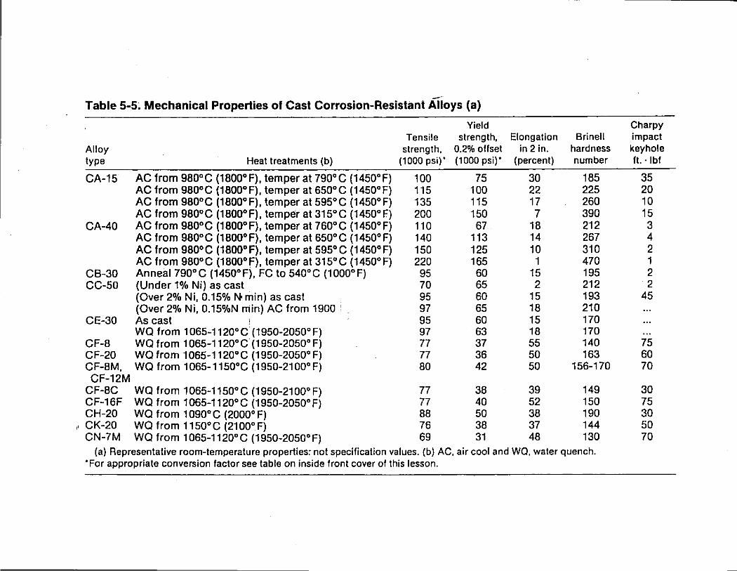
-Table 5-5; Mechanical Properties of Cast Corrosion-Resistant Alloys (a)
Yield Charpy Tensile strength, Elongation Brinell impact
Alloy strength, 0.2% offset in 2 in. hardness keyhole type Heat treatments (b) (1000 psi)' (1000 psi)' (percent) number ft. · I bf
CA-15 AC from 98o•c (18oo•F), temper at 790"C (1450"F) 100 75 30 185 35 AC from 980"C (1800°F), temper at 650°C (1450°F) 115 100 22 225 20 AC from 980°C (1800°F), temper at 595°C (1450"F) 135 115 17 260 10 AC from 98o•c (18oo•F), temper at 315"C (1450"F) 200 150 7 390 15
CA-40 AC from 980°C (18oo•F), temper at 760"C (1450°F) 110 67 18 212 3 AC from 98o•c (18oo•F), temper at 65o•c (1450°F) 140 113 14 267 4 AC from 980°C (1800"F), temper at 595°C (1450°F) 150 125 10 310 2 AC from 98o•c (1800°f), temper at 315"C (1450°F) 220 165 1 470 1
CB-30 Anneai790"C (1450°F), FC to 540"C (1000°F) 95 60 15 195 2 CC-50 (Under 1% Ni) as cast ' 70 65 2 212 2
(Over 2% Ni, 0.15% No min) as cast 95 60 15 193 45 (Over 2% Ni, 0.15%N min) AC from 1900 97 65 18 210
CE-30 As cast 95 60 15 170 WQ from 1065-1120"C(1950-2050"F) 97 63 18 170
CF-8 WQ from 1065-1120"C (1950-2050" F) 77 37 55 140 75 CF-20 WQfrom 1065-1120"C (1950-2050"F) 77 36 50 163 60 CF-8M, WQ from 1065-1150"C (1950-2100"F) 80 42 50 156-170 70 CF-12M
CF-8C WQ from 1 065-1150" C (1950-21 00" F) 77 38 39 149 30 CF-16F WQ from 1065-1120° C (1 950-2050" F) 77 40 52 150 75 CH-20 WQ from 1090"C (2000"F) 88 50 38 190 30 CK-20 WQ from 1150"C (2100"F) 76 38 37 144 50 CN-7M WQ from 1065-112o•c (1950-2050"F) 69 31 48 130 70
(a) Representative room-temperature properties: not specification values. (b) AC, air cool and WQ, water quench. ·For appropriate conversion factor see table on inside front cover of this lesson.
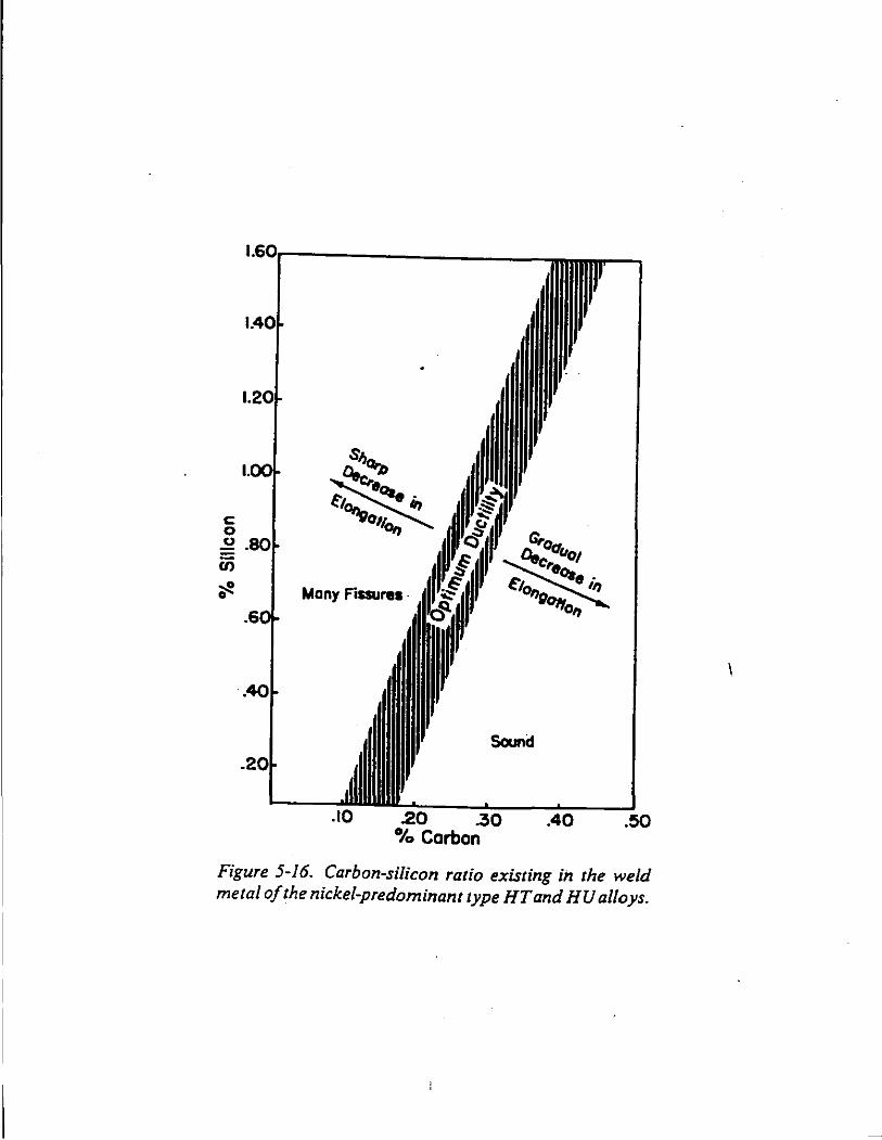
c:: 0 ~ C/)
~ 0 Many Fissures .
Sound
.10 .20 .30 .40 .!SO %Carbon
Figure 5-16. Carbon-silicon ratio existing in the weld metal of the nickel-predominant type HTand HU alloys.
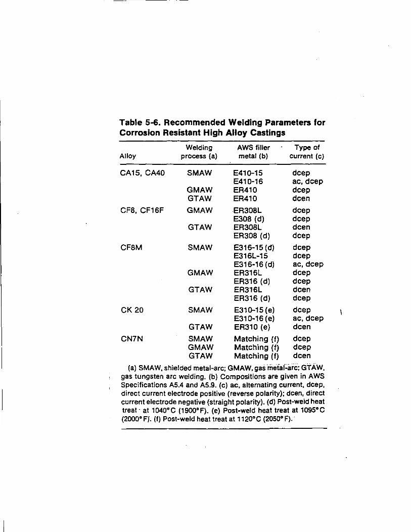
Table 5-6. Recommended Welding Parameters for Corrosion Resistant High Alloy Castings
Welding AWS filler Type of Alloy process (a) metal (b) current (c)
CA15, CA40 SMAW E410-15 deep E410-16 ac, deep
GMAW ER410 deep GTAW ER410 dcen
CFB, CF16F GMAW ER308L deep E308 (d) deep
GTAW ER308L dcen ER308 (d) deep
CFBM SMAW E316-15 (d) deep E316L-15 deep E316-16 (d) ac, deep
GMAW ER316L deep ER316 (d) deep
GTAW ER316L dcen ER316 (d) deep
CK20 SMAW E310-15 (e) deep E310-16 (e) ac,dcep
GTAW ER310 (e) dcen
CN7N SMAW Matching (f) deep GMAW Matching (f) deep GTAW Matching (f) dcen
(a) SMAW, shielded metal-arc; GMAW, gas ·mefaf~ari:; GTAW, gas tungsten arc welding. (b) Compositions are given in AWS Specifications A5.4 and A5.9. (c) ac, alternating current, deep, direct current electrode positive (reverse polarity); dcen, direct current electrode negative (straight polarity). (d) Post-weld heat treat· at 1040"C (1900"F). (e) Post-weld heat treat at 1095"C (2000" F)". (f) Post-weld heat treat at 1120"C (2050" F).·
I
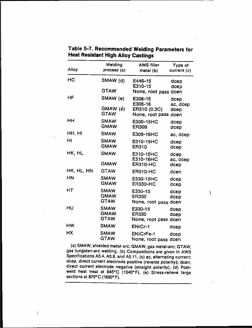
Table 5-7. Recommended Welding Parameters for Heat Resistant High Alloy Castings
Alloy
HC
HF
HH
HH, HI
HI
HK,HL
HK, HL, HN
HN
HT
HU
HW
HX
Welding process (a)
SMAW (d)
GTAW
SMAW (e)
GMAW (e) GTAW
SMAW GMAW
SMAW
SMAW GMAW
SMAW
GMAW
GTAW
SMAW GMAW
SMAW GMAW GTAW
SMAW GMAW GTAW
SMAW
SMAW GTAW
AWS filler Type of metal (b) current (c)
E446-15 deep E310-15 deep None, root pass deen
E308-15 deep_ E308-16 ae,deep ER310 (0.3C) deep None, root pass deen
E309-15HC deep ER309 deep
E309-16HC ae,dcep
E310-15HC deep ER310 deep
E310-15HC deep E310-16HC ae,deep ER310-HC deep
ER310-HC de en
E330-15HC deep ER330-HC deep
E330-15 deep ER330 deep None, root pass deen
E330-15 deep ER330 deep None, root pass deen
ENiCr-1 deep
ENiCrFe-1 deep None, root pass deen
(a) SMAW, shielded metal-arc; GMAW, gas metal-arc; GTAW. gas tungsten-arc welding. (b) Compositions are given in AWS Specifications A5.4, A5.9, and A5.11. (c) ac, alternating current; deep, direct current electrode positive (reverse polarity); dcen, direct current electrode negative (straight polarity). (d) Postweld heat treat at B45"C (1040"F). (e) Stress-relieve large sections at 870" C (1600" F). ·

Figure 5-2. Valves made oftype CN-lMCu used for handling 93 to 98% sulfuric acid.
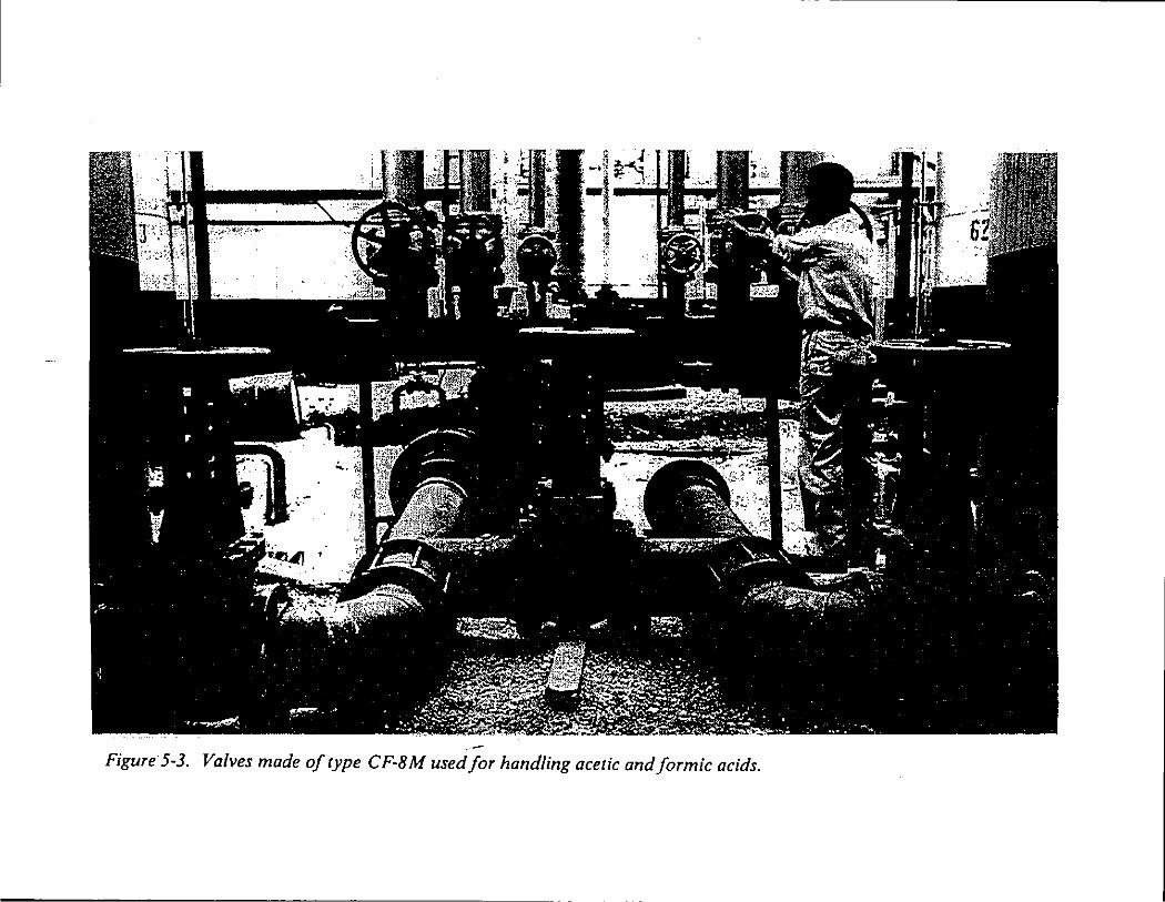
Figure· 5-3. Valves made of type CF-BM used for handling acetic and formic acids.
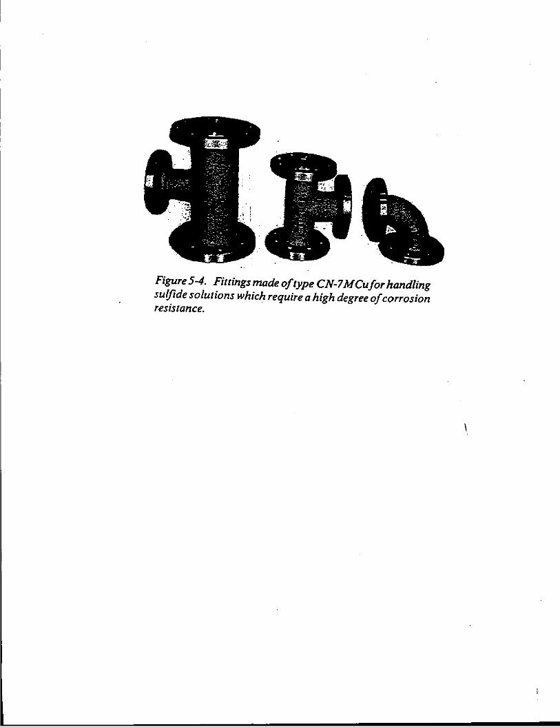
Figure 5-4. Fittings made of type CN-7 MCufor handling sulfide solutions which require a high degree of corrosion resistance.
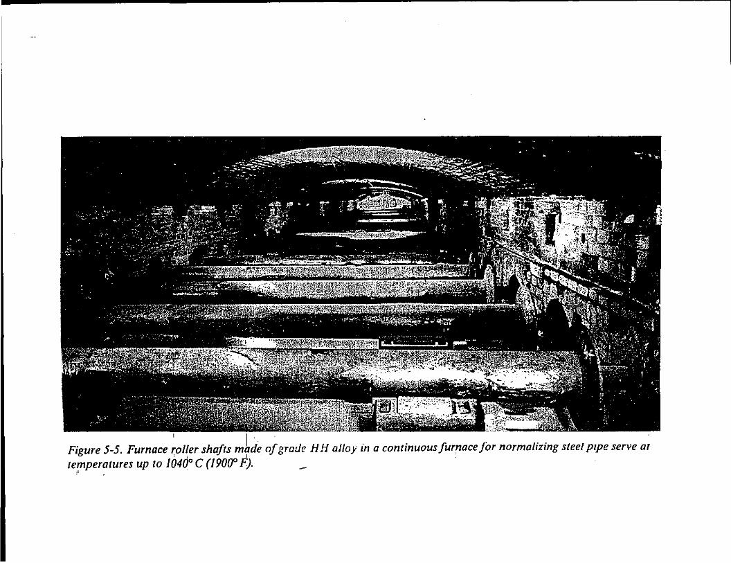
Figure 5-5. Furnace r:oller shafts of grade H H al/o y in a continuous furnace for normalizing steel p1pe serve ar . • I
temperatures up to 1040° C (19000 F). ~ .
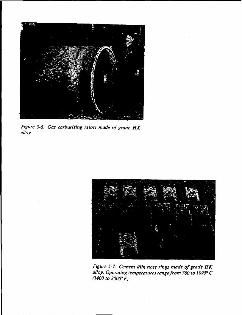
Figure 5-6. Gas carburizing retort made of grade HX alloy.
Figure 5-7. Cement k"i/n nose rings made of grade H K alloy. Operating temperatures range from 760 to 1095° C (1400 to 2000° F).
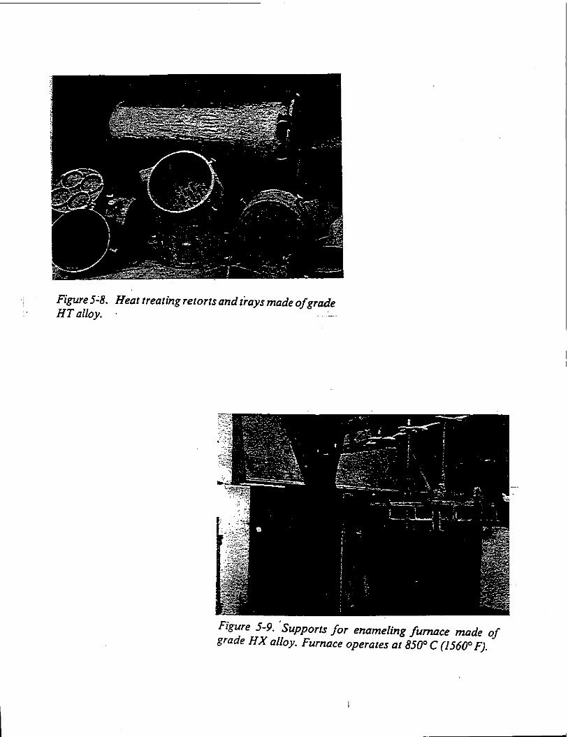
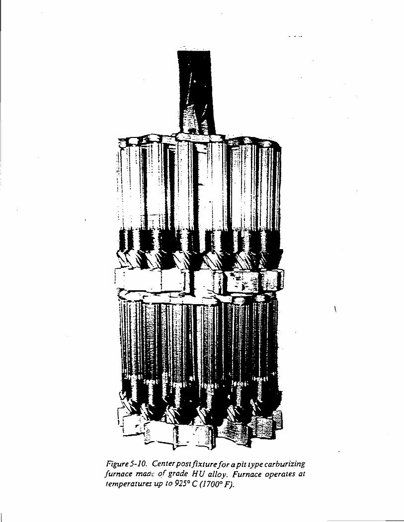
' ' ""' r I ;• I '-'
~~ ;:;,;; --
Figure 5-10. Center post fixture for a pit type carburizing furnace maci,· of grade HU alloy. Furnace operates at temperatures up to 925° C (1700° F).
I
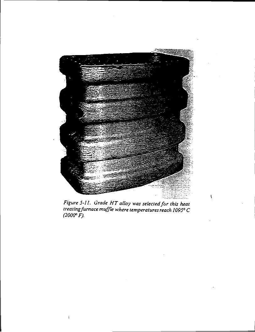
Figure 5-11. Grade HT alloy was selected for this heat treatingfurnace muffle where temperatures reach 1095° C (2000C F).
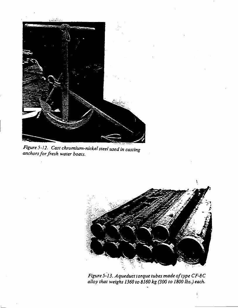
Figure 5-12. Cast chromium-nickel steel used in casting anchors for fresh water boats.
\.
Figure 5-"n. Aqueduct torque tubes made of type CF-8C alloy that weighs 1360 to 8160 kg (30() to 1800 lbs.) each.
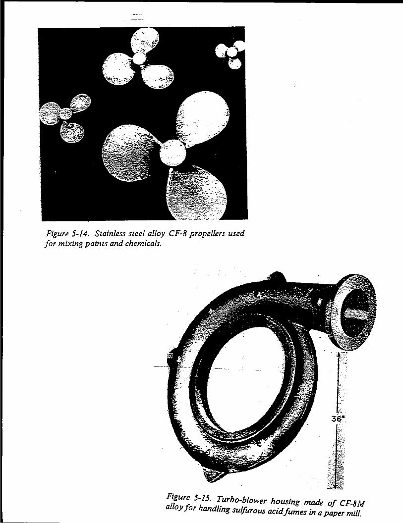
Figure 5-14. Stainless steel. alloy CF-8 propellers used for mixing paints and chem1cals.
Figure 5-15. Turbo-blower housing made of CF-8M alloy for handling sulfurous acid fumes in a paper mill.
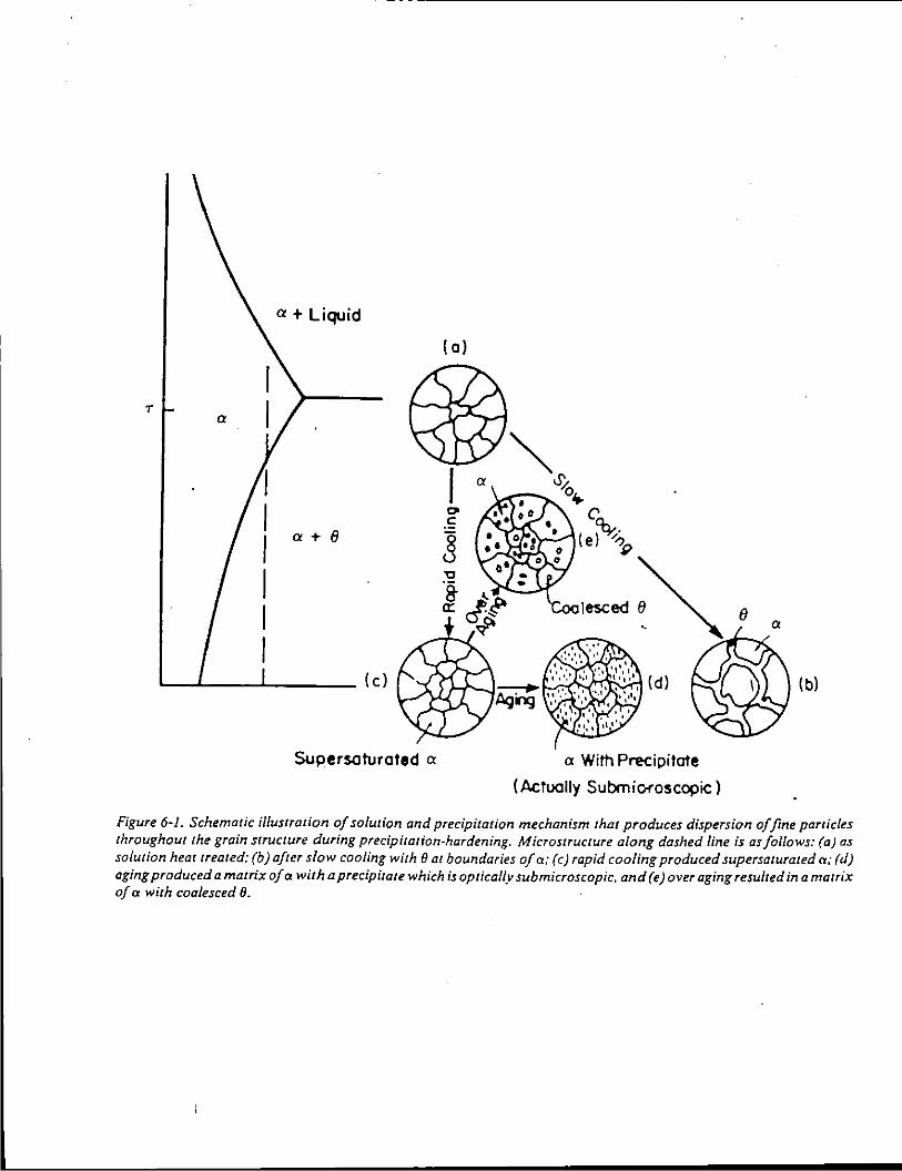
a+ Liquid
T
a + ()
(c)
Supersaturated a
( 0)
I 0 .s ]
a
a With Precipitate
(Actually SubmiOf"oscopic)
(b)
Figure 6-1. Schematic illustration of solution and precipitation mechanism that produces dispersion of fine particles throughout the grain struciUre during precipitation-hardening. Microstructure along dashed line is as follows: (a) as solution heat treated: (b) after slow cooling with 8 at boundaries of a: (c) rapid cooling produced supersaturated cr: (d) aging produced a matrix of a with a precipitate which is optically submicroscopic, and (e) over aging resulted in a matrix of a with coalesced 8.
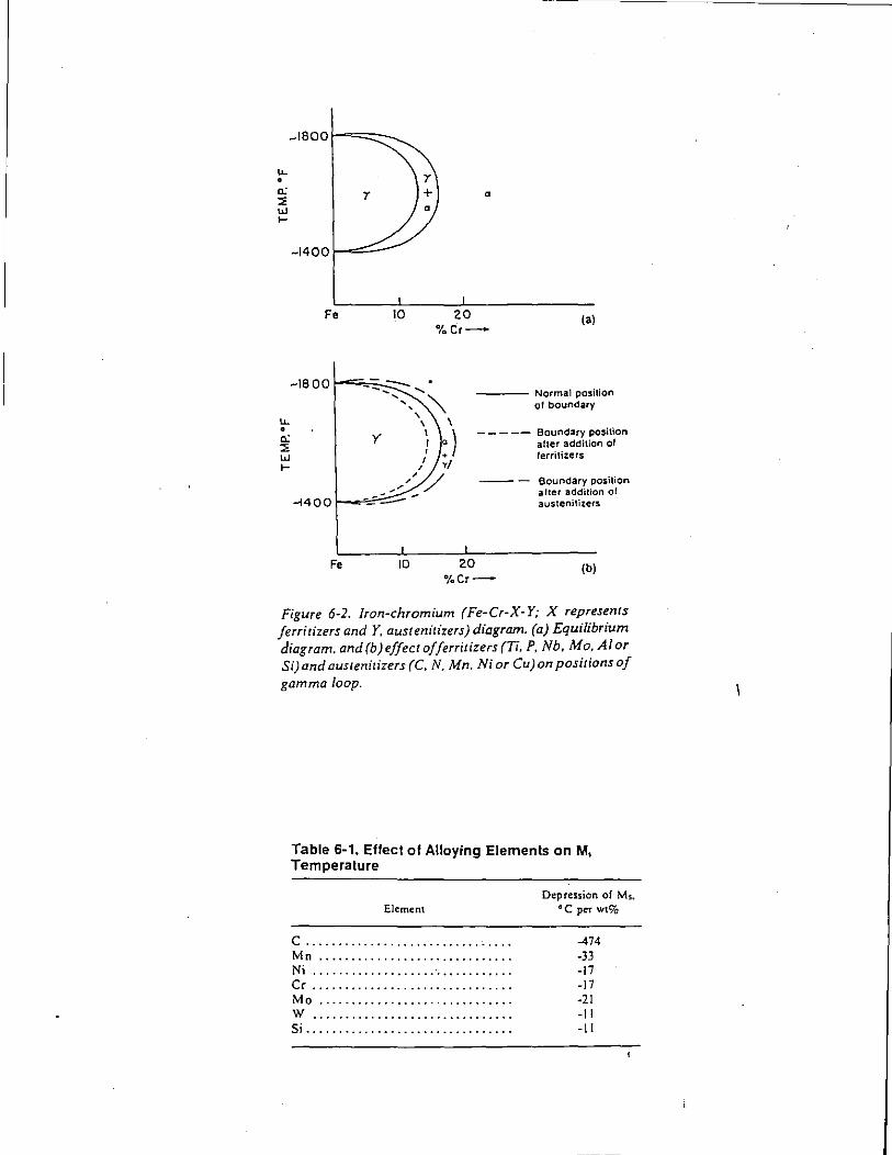
~1800
lL • 0: ::E UJ ....
lL • 0: ::E UJ ....
~1400
Fe 10
Fe 10
a
20 %Cr-
(a)
---- Normal position of boundary
----- Boundary position alter addition ol lerrilizers
20 %Cr-
Boundary position after addition of austenitizers
(b)
Figure 6-2. Iron-chromium (Fe-Cr-X-Y; X represents Jerritizers andY, austenitizers) diagram. (a) Equilibrium diagram. and (b)effect offerritizers (Ti, P, Nb, Mo, AI or Si) and austenitizers (C, N, Mn. Ni or Cu) on positions of gamma loop.
Table 6-1. Effect of Alloying Elements on M, Temperature
Element
c ............................... . Mn ............................. . Ni .............................. . Cr .............................. . Mo ............................. . w .............................. . Si ............................... .
Depression of Ms. °C per wt%
-474 -33 -17 -17 -21 -II -II
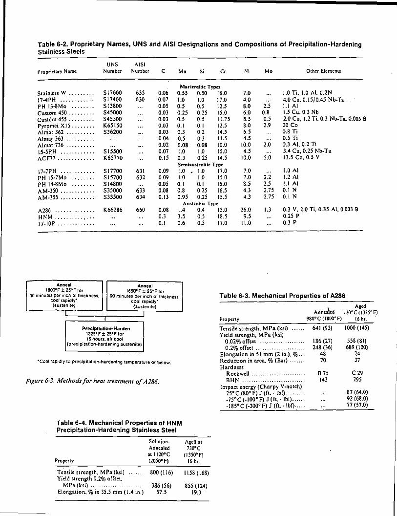
Table 6-2. Proprietary Names, UNS and AISI Designations and Compositions of Precipitation-Hardening Stainless Steels
UNS A lSI Proprietary Name Number Number c Mn Si Cr Ni Mo Other Elemems
Martrnsilic Types Stainless W ......... 517600 635 0.06 0.55 0.50 16.0 7.0 1.0 Ti. 1.0 AI, 0.2N 17-4PH . . . . . . . . . . . . 517400 630 O.Q7 1.0 1.0 17.0 4.0 4.0 Cu. 0.15/0.45 Nb-Ta PH 13·8Mo ........ 513800 0.05 0.5 0.5 12.5 8.0 2.5 1.1 AI Custom 450 ......... 545000 0.03 0.25 0.25 15.0 6.0 0.8 I.S Cu. 0.3 Nb Custom 455 ......... 545500 0.03 0.5 0.5 II. 75 8.5 0.5 2.0 Cu, 1.2 Ti. 0.3 Nb-Ta. 0.005 B Pyromei X 15 ........ K65150 0.03 0.1 0.1 12.5 8.0 2.9 20 Co A I mar 362 .......... 536200 0.03 0.3 0.2 14.5 6.5 0.8 Ti Almar 363 .......... 0.04 0.5 0.3 II.S 4.5 0.5 Ti Almar·736 .......... O.o2 0.08 0.08 10.0 10.0 2.0 0.3 AI. 0.2 Ti !5-5 PH ········· ... 515500 O.Q7 1.0 1.0 15.0 4.5 3.4 Cu, 0.25 Nb-Ta ACF77 ............. K65770 0.15 0.3 0.25 14.5 10.0 5.0 I 3.5 Co. 0.5 V
Srmiaustcnitic Type 17-7PH . . . . . . . . . . . . 517700 631 0.09 1.0 1.0 17.0 7.0 1.0 AI PH !5-7Mo ........ 515700 632 0.09 1.0 1.0 15.0 7.0 2.2 1.2 AI PH 14-SMo ........ 514800 0.05 0.1 0.1 15.0 8.5 2.5 1.1 AI AM-350 ............ 535000 633 0.08 0.8 0.25 16.5 4.3 2.75 0.1 N AM-355 ........... : 535500 634 0.13 0.95 0.25 15.5 4.3 2.75 0.1 N
Austenitic Type
A286 .............. K66286 660 0.08 1.4 0.4 HNM .......... , ... 0.3 3.5 0.5 17-IOP ............. 0.1 0.6 0.5
Anneal Anneal t800"F ± 25" F for 1650"F ± 2S"F for
r)O minutes per inch of thickness, 90 minutes per inch of thickness, cool rapidly' cool rapidly'
(austenite) (austenite)
I
Precipitation-Harden 1325"F ± 25"F for 16 hours. air cool
(precipitation-hardening austenite)
·cool rapidly to precipitatiOn·hardening temperature or below.
Figure 6-3. Methods for heat treatment of A286.
Table 6-4. Mechanical Properties of HNM Precipitation-Hardening Stainless Steel
SolutionAnnealed at 1)2Q°C
Property {2050° f)
Tensile strength. MPa (ksi) 800 (116) Yield strength 0.2% offset,
MPa (ksi) .. .... .. .. .. . .. . . . . . . .. 386 (56) Elongation,% in 35.5 mm (1.4 in.) 57.5
Aged at 730'C
(I 350' F) 16 hr.
1158(168)
855 (124) 19.3
15.0 26.0 1.3 0.3 V. 2.0 Ti, 0.35 AI, 0.003 B 18.5 9.5 0.25 p 17.0 11.0 0.3 p
Table 6-3. Mechanical Properties of A286
Property
Tensile strength. MPa (ksi) Yield strength, MPa (ksi)
0.02% offset ................... . 0.2% offset ..................... .
Elongation in 51 mm (2 in.). % .. . Reduction in area.% (Bar) ...... . Hardness
Rockwell ....................... . BHN ........................... .
Impact energy (Charpy Y·notch) 25'C (80'F) J (ft.· lbf) ........ . -75°C (-100°F) J (ft. ·lbf) ..... . -185'C (-300' F) J (ft.· lbf) .... .
Aged Annea\.ed 720'C ( 1325' F)
980'C (I BOO' F) 16 hr.
641 (93) 1000 (145)
186 (27) 558 (81) 248 (36) 689 (100)
48 24 70 37
B 75 C29 143 295
87 (64.0) 92 (68.0) 77 (57.0)
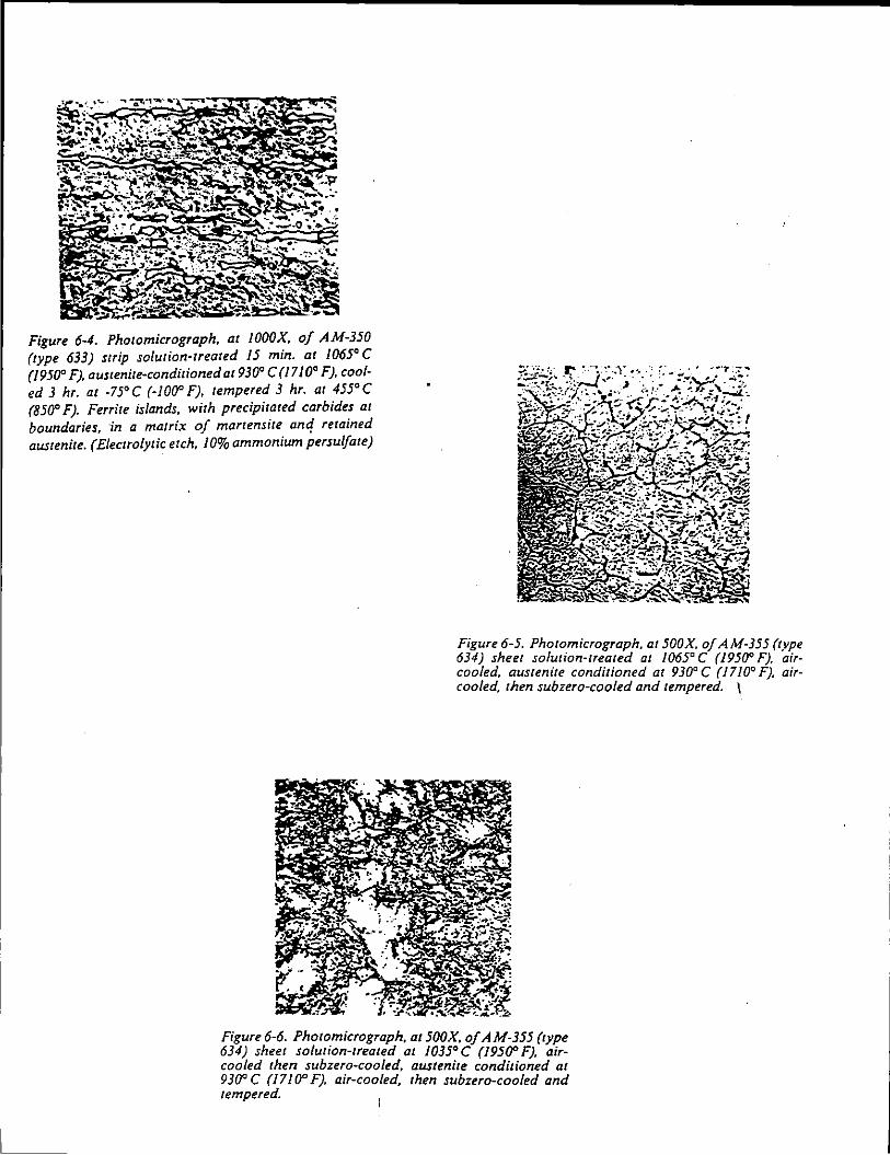
Figure 6-4. Photomicrograph. at JOOOX. of AM-350 (type 633) strip solution-treated I 5 min. at /065' C (19500 F), austenite-conditioned at930' C (17/0' F). cooled 3 hr. at ·75'C (-100' F), tempered 3 hr. at 455'C (850' F). Ferrite islands. with precipitated carbides at boundaries. ·fn a matrix of martensite anc! retained austenite. (Electrolytic etch. 10% ammonium persu/fate)
Figure 6-5. Photomicrograph. at 500X. of A M-355 (type 634) sheet solution-treated at 1065' C (1950' F). aircooled, austenite conditioned at 930' C (1710' F). aircooled, then subzero-cooled and tempered. 1
Figure 6-6. Photomicrograph, at500X. of AM-355 (type 634) sheet solution-treated at 1035'C (19500 F). aircooled then subzero·cooled. austenite conditioned at 930' C (1710' F). air-cooled, then subzero-cooled and tempered.
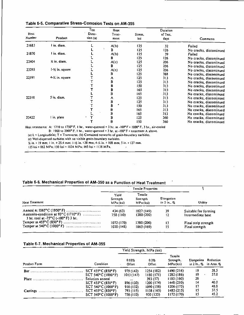
Table 6-5. Comparative Slress-Corrosion Tesls on AM-355
Test Heat Duration Heat Dirc:c- Treat- Stress, of Test,
Number Product tion (a) ment ksi days
21683 I in. diam. L A( b) 125 32 L B 125 126
21870 I in. diam. L A( b) 125 39 L B 125 126
22404 ~in. diam. L A( c) 125 206 L B 125 206
23295 1-~ in. square L A( c) 125 206 L B 125 388
22,191 4-V. in. square T A 125 313 T B 125 313 T B 150 313 T B 165 313 L B 16S 313
22310 5 in. diam. T A 12S 313 T B 12S 313 T B ISO 313 T B 16S 313 L B 16S 313
23422 I in. plate T B 12S 360 T B ISO 360
Heat treatments: A: 1710 to 1750°F, I hr .. water-quenced + 3 hr. at -100°F + 1000°F, 3 hr .. air-cooled 8: 1900 to 2000° F. I hr., water-quenced + 3 hr. at -100°F +treatment A above.
(a) L = Longitudin'al; T =Transverse. (b) Contained networks of grain-boundary carbides. {c) Well-dispersed carbides with no visible grain-boundary carbides. y. in.= 19 mm: I in.= 25.4 mm: 1-Vz in. =38 mm: 4-V. in.= 108 mm: 5 in.= 127 mm. 125ksi '862 MPa: 150 ksi' 1034 MPa: 165 ksi' 1118 MPa.
Table 6-6. Mechanical Properties of AM-350 as a Funclion of Heal Trealmenl
Tensile Properties
Heat Treatment
Yield Strength MPa (ksi)
Tensile Strength MPa (ksi)
Elong:uion in 2 in .. %
Anneal ati06s•c (1950°F) ........................ . A ustenite-conditiori at 93° C ( 1710° f) ............ .
434 (63) 758(110)
1027 (149) 1380 (200)
3 hr. cool at -75° C (-100° F) 3 hr. Temper at4ss•c (850°F) .......................... . Temper atS40°C (1000° F) ........................ .
1072 (170) 1020(143)
1380 (200) 1065(169)
Table 6-7. Mechanical Properties of AM-355
Yield Strength. MPa (ksi)
0.02% 0.2% Product Form Condition Offset Offset
Bar .......... ........................... SCT 4SS• C (8SO• F) 979 (142) 12S4 (182) SCT S40°C (IOOO•F) 1013(147) 1180 (171)
Plate ........ . . . . . . . . . . . . . . . . . . . . . . . . . . - Solution anneal 393 (57) SCT 4SS• C (8So• F) 896 ( 130) 1200(174) SCT 540°C (IOoo•F) 910 (132) 1090(158)
Castings ............................ _ . _ . SCT 4S5•C (8SO•F) 793 (liS) 1138 (16S) SCT S40•C (IOOO•F) 7S8 (110) 930 (135)
39 12
13 IS
Tensile Strength. MPa (ksi)
1490(216) 1282(186) 1103(160) 1448(210) 1206(17S) 1482 (21S) 1172 (170)
Comments
Failed No cracks, discontinued Failed No cracks, discontinued No cracks, disconiinued No cracks, discontinued No cracks, discontinued No cracks, discontinued No cracks, discontinued No cracks, discontinued No cracks, discontinued No cracks, discontinued No cracks, discontinued No cracks, discontinued No cracks, discontinued No cracks, discontinued No cracks, discontinued No cracks, discontinued No cracks, discontinued No cracks, discontinued
Utility
Suitable for forming Intermediate heat
Final strip strength Final strength
Elongation Reduction in 2 in .. % in Area.%
19 38.5 19 S7.0 26 14 40.0 17 48.0 15 37.5 15 4S.2
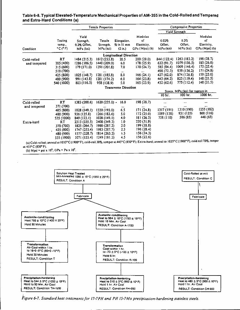
Table 6-8. Typical Elevated-Temperature Mechanical Properties of AM-355 in the Cold-Rolled and Tempered and Extra-Hard Conditions (a)
Condition
Cold-rolled and tempered
Cold-rolled and tempered
Testing temp .. oc (oF)
RT 205 (400) 315(600) 510 (700) 425 (800) 480 (900)
540 ( 1000)
RT 371 (700)
Tensile Propenic:s
Yield Modulus Strength. Tensile Elongation. of
0.2% Offset. Strength. %in 51 mm Elasticity. MPa (ksi) MPa (ksi) (2 in.) GPa (Mpsi) (b)
Longitudinal Direction 1484 (215.3) 1612 (233.8) 20.5 200 (29.0) 1286 ( 186.5) 1440 (209.0) 6.0 178 (25.9) 179 ( 171.0) 1391 (201.8) 7.0 170 (24.7)
1025 (148.7) 1281 (185.8) 8.0 166(24.1) 991 (143.8) 1201 (174.2) 6.0 164 (23.8) 803 (116.5) 958 (138.9) 5.0 165 (23.9)
Transverse Direction
1383 (200.6) 1620 (235.0) • 16.0 198 (28.7)
485 (800) 1028 (149.1) 1330 (193.0) 6.5 171 (24.8) 480 (900) 936 (135.8) 1266 (183.6) 5.0 172 (25.0) 535(1000) 849(123.1) 1028(149.1) 4.0 181 (26.2)
RT 2313 (335.5) 2408 (349.3) 1.0 220 (31.9) 370 (700) 1825 (264.7) 1980 (287.2) 2.0 199 (28.8) 425 (800) 1747 (253.4) 1983 (287.7) 2.5 196 (28.4) 480 (900) 1577 (228.7) 1814 (263.2) 1.5 156 (24.3) 535 (1000) 1071 (155.4) 1249 (181.2) 4.5 156 (22.6)
Compressive Properties
Yield StrenS!h
Modulus 0.02% 0.2% of Offset. Offset. Elasticity,
MPa (ksi) MPa (ksi) GPa (Mpsi) (b)
844(122.4) 1263 ( 183.2) 198 (28.7) 632 (91.7) 1079 (156.5) 185 (26.8) 585 (84.4) I 009 ( 146.4) 175 (25.4) 498 (72.3) 939 (136.2) 171 (24.8) 427 (62.0) 874 (126.8) 159 (23.0) 443 (64.2) 823 (119.4) 148 (21.5) 432 (62.6) 775 (ll2.4) 148 (21.5)
Stress. MPa (k.si) ror rUJ:!lUre in 10 hr.
1317 (191) 1089 (158) 758 (Ito)
100 hr.
1310 (190) 931 (135) 586 (85)
1000 hr.
1255 (182) 800(116) 448 (65)
(a) Cold-rolled: anneal at 1035° C ( 1900° F), co\d-ro\130%. temper at 445°C (850° F): Extra-hard: anneal to 1035° C ( 1900° F), cold ro1170%. temper
at 455° C (850° F). (b) Mpsi =psi x \06
: GPa = Pax 109•
Solution Heat Trealed Cold-Rolled at mill Mill-Annealed 1066 ± 15°C (1950 ± 25°F) RESULT; Condition A
RESULT: Condition C
I ' I Fabricate I j Fabricate j
~ ~ Austenlle-condlllonlng
Austenite conditioning Heal to 954 ±: 10'"C (1750 ± 15°F)
Heat 760 ± t5°C (1400 x 25°F) Hold 10 Min. Air Cool Hold 90 Minutes RESULT: Condition A·1750
Transformallon Tranaronnallon Air Cool within 1 hr. Cool within 1 hr. to 16•0 ·5'"C (60+0 ·10° F) to ·73 ± 5°C (·100 ± 10°F) Hold 30 Minutes Hold 8 hr. RESULT: Condition T RESULT: Condition R·lOO
Preclpltallon·hardenlng Preclpltallon·hardenlng Heat to 544 ± 5°C ( 1 050 ± 10" F) Heat to 510:: S°C (950 ± 10°F) Hold to 90 Min. Air Cool Hold 1 hr. Air Cool
Precipitation-hardening Heat 10 480 ±sac (900 = 10°F) Hold 1 hr. Air Cool
RESULT: Condition TH·1U50 _ RESULT: Condition AH·950 RESULT: Condition CH·900
hgure 6-7. Standard heat treatments for 17-7PH and PH /5-7Mo precipitation-hardening stainless steels.

11-TPH Condition TH-1050 17-7PH Condiiton AH-950 ;
1700 i' 240
i ~ 1500 ll_2201 _ __;_ ____ .;_. ___ r--· ~ "' Ultimate tensile slreng __ 1_h _!_ --~-J ..; =:;2001
~ 1300 u1 \ 5! Ill 180 ~ O.?'lo
1
yield Slrength_ .••. _ .;
I a· · 1 ElongatiOn -~
11 00 t&o 1---- r - • · , -··r--:-·-----la "" 1 ; ! • : 1 • s· ~-·\;!; 1 · -,-··---r----!--,-.:::~=,-~...;__...J. § I ' . .
l ' . \ ~o--l. _ _i_L
I i i ; 1800 1900 2000 2100 2200
Solution treatment temperature, G F Solution treatment temperature. • F
1000 1100 1200 1000 1100 1200 Solution treatment temperature. •c Solution treatment temperature, "C
Figure 6-8. Effect of solution-treatment temperature on final properties of 17-7 PH. (a) TH-1050 and (b) RH-950. (Courtesy Armco Steel Corporation)
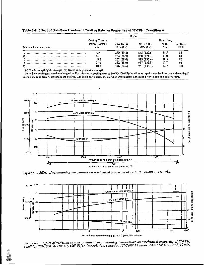
-· ... ...... iJ ~g:.;
Table 6-9. Effect of Solution-Treatment Cooling Rate on Properties of 17-7PH, Condition A
Solution Treatment. min.
2 ··················································· 20 .................................................. .
2 5
15
, Cooling Time to 540'C (IOOO'F)
min.
Air Air
9.5 27.0
I 10.0 (a) Notch strength/yield strength. (b) Notch strength/tensile strength.
Ratio
NS/YS (a) MPa (ksi)
270 (39.2) 254 (36.9) 262 (38.0) 262 (38.0) 376 (54.6)
Elongation, NS/TS (b). %in. MPa (ksi) 2 in.
845 ( 122.6) 41.5 860 (124.7) 39.0 919 (133.4) 28.5 937 (I 35.8) 17.7 951 (138.1) 12.7
Hardness, HRB
S5 84 86 91 100
Note: $\ow cooling rates reduce elongation. For this reason, cooling rates to 540° C ( 1000° f) should be as rapid as obtained in normal air cooling if satisfactory condition A properties are desired. Cooling is particularly critical when intermediate annealing prior to addition cold working.
210
1400 200 ' --1300 190
• .. o; 160 ::; ~
~
~1200 :i ~ • u; Ji 170
......_ 1100 160
150
1000
1200
650
Ult'Jate tenLe stretth
J I I I
0.2% yield strength I
Elongation
1300
-- -·--I
1400 Austenite-conditioning temperature, oF
750 Austenite-conditioning temperature. oc
- i ---r--...............
"'-.,
""' 1500
Figure 6-9. Effect of conditioning temperature on mechanical properties of 17-7 PH. condition TH-1050.
1500 220
200
• ..: .. ::e 1250 ·;-; 180 ..; • ~
~ ,; u; • •
I I I IT II Ultimate tensile strength
' I I I I I I 0.2Gfa yield strength
I ..--$160
~
850
m 0 , c • g-? -1'
1 0 ~ §
8
6
4
II ! : I
I 1
3 3
1000 I 140 Elongation
1 o·~ .:.
5 10 50 100
Austenite-conditioning lime at 760°C (1400° F), minutes
500 1 8
000
Figure 6-10. Effect of variation in time at austenite-conditioning temperature on mechanical pr~perties ~f 17-7 PH. condition TH-1050. At 760° C (1400° F)fortime solution, cooled to 16° C (60° F). hardened at566 C (1050 F)90 mtn.
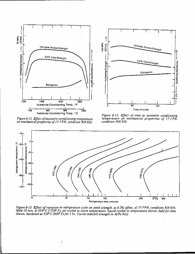
~~ ::;~
o!: ~-
Ultimate Tensile Strength
l .c 0, 0-2% Yield Strength c ~ ;;;
"' ;-.s n 0 ;; • • ! • u ;-.s "' m
0 , "' •
Elongation =· 0 ,
1200
Austenite-Conditioning Temp., ° F
700 BOO 900 1000 Austenite-Conditioning Temp., oc
Figure6-1 1. Effect of austenite-conditioning temperature on mechanical properties of 17-7 PH. condition RH-950.
;l ,f ~ ~ ·25~ 0. •
e "'e • - -40 !!! g c ~ .g -50 :u e "' . ::: .g' £ Qi
a: -75 ·60
-100 -75
10
t • 0.. "iii. Ultimate 7 ::; ~ - ensiles 0 0 lrength :! !:'.
r -=· - 0-2% Yield St
"' rength c ~ -;;;
"' Elongation c .. • ~ u .=
l
Time, minutes
Figure 6-12. Effect of time at austenite conditioning temperature on mechanical properties of 17-7PH. condition RH-950.
Refrigeration time. minutes
Figure 6·13. Effect of variation in refrigeration cycle on yield strength. at 0.2% offset. of 17-7 PH, condition RH-950. Held 10 min. at 954" C (1750° F). air-cooled to room temperature, liquid-cooled to temperature shown. held for time shown, hardened at 510° C (950" F) for 1 hr. Curves indicat~ strength in M Pa (ksi).
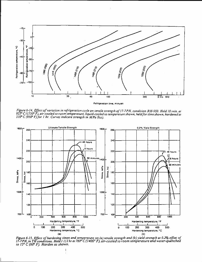
-10
0
·20
~ ~ . . ·25
.,; e ; .. ;; ~ • -40 • 0. 0. E·SO E .! .! 0 0 §' .g .Q
~ ~ ~
. ~-75 0 • ~
"' -60 E ::! ;;; • • a: a:
-75 -100
10
Refrigeration time. minutes
Figure 6-14. Effect of variation in refrigeration cycle on tensile strength of I 7-7 PH, condition RH-950. Held 10 Min. at 955° C (1750° F), air-cooled to room temperature, liquid-cooled to temperature shown, held for time shown, hardened at 5/0° C (950° F) for I hr. Curves indicate strength in M Pa (ksi).
1800
1400
1000
700
260
240
220
200
·;:;; 180 ~
.,; • e (i) 16 0
14 0
0 12
10 0
-
0 200
0 100
Ultimate Tensile Strength
/ -5: 48l hou's
8 hours
(( H ~:a minut
1/ \
_,A w \\\ .... ~ I \1
400 600 800 1000
Har~_ening temperature, "F
200 300 400 500
1800
es1400
1000
700
.. ~
260
240
220
200
:: 180 e in
16 0
14 0
12 0
10 0 0
0 2"!. Yield Strength . .
r 48 hours
/ Q ~8hou" (I, v-- ~minutes
v ~\_ ~ l\ \ /.
~ \
[7 200 400 600 800 1000
Hardening temperature. '"F
0 100 200 300 400 500· Hardening temperature. "C Hardening temperature. "C
00 (b) Figure 6-15. Effect of hardening times and temperature on (a) tensile strength and (b) yield strength at 0.2% offset of 17-7 PH, in TH conditions. Held I I /2 hrat 760° C (1400° F), air-cooled to room temperature and water-quenched to /5° C (600 F). Harden as shown.

tHble 6-10. Effect of Hardening Temperature on Notch Strength (a)
Yield Precipitation- Strength Tensile Notch
Hardening 0.2% Offset. Strength. Strength. Treatment MPa {ksi) MPa (ksi) MPa (ksi) NS/YS (b) NS/TS (c)
RH-950 1572 (228) 1703 (247) 745 ( 108) 0.47 0.44 RH-1000 1586 (230) 1675 (243) 965(140) 0.61 0.58 RH-1050 1517 (220) 1565 (227) 1117 (162) 0.74 0.71 RH-1100 1255 (182) 1324 (192) 1200 (174) 0.96 0.91
1/·II'H .......................... . RH-950 1517 (220) 1627 (236) 827(120) 0.55 0.51 RH-1000 1413 (205) 1544 (224) 738 ( 107) 0.52 0.48 RH-1050 1276 (185) 1413 (205) 1103(160) 0.86 0.78 RH-1100 931 (135) 1207 (175) 1082(157) 1.18 0.90
1 ;~) PH IS-7Mo specimen 0.063 in. (1.60 mm) and 17-7PH specimens 0.050 mm (0.020 in.). All25.4 mm (I in.) wide .DIS mm (0.0007 in.) max root r 111 Jiu~. All tests in transverse direction. (b) Notch strength{ yield strength. (c:) Notch strength/tensile strength.
Jl:ll:t courtesy of NASA- Lewis Laboratory.
Fi~'"' 6-16. Photomicrograph. at 500X. showi'!g as•
1 •11Jed microstructure of 17-4PH. Structure IS un-
a/11' · · · · I I d l .r 11 pered martenswc matnx wrt r e ongate poo s o1
/.:rite. Etchant: HCI-Picric acids.
F' 6_17 Photomicrograph. at 500X. showing m'i~~~:tructu~e of 17-4PH. condition H-1075. Etchant: HCI-Picric acids. ·
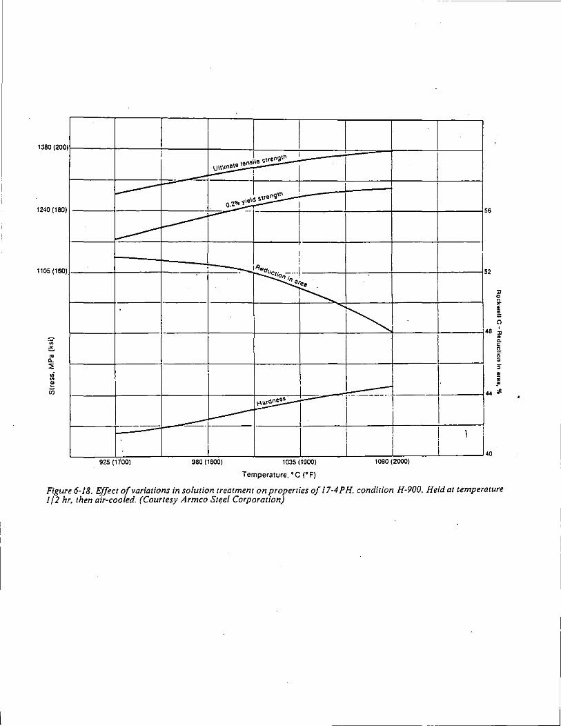
1380 (200 )
--1240 (180 )
----1105 (160 )
925(1700)
I gto I '\e streo
uu;rnate \ensl !
-I ! '" . "\~ o.2ot.J!. I -
----~-
-
-
' ; - iRea i
~ .
.
I
~
~r-- .
i 980 (1800) 1035 (1900)
Temperature, °C (°F)
I
I I
I
I
5 6
5 2
l! 0 n
~ 4 I
~ • g, 0
8 ' l! • 0. c n g ,
J -···
" • • ~
I I \
I. i 0 1090 (2000)
Figure 6-18. Effect of variations in solution treatment on properties of 17-4PH. condition H-900. Held at temperature I/ 2 hr. then air-cooled. (Courtesy Armco Steel Corporation)
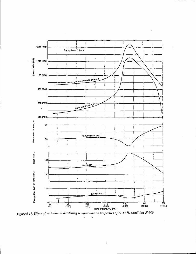
I I
1J8Q {2QQ) 1 ·---l-------· --·------' ' I
:_~~
'··· :~ ___ ;~ Ag•ng lime: 1 hour
~ ... ,~1 , , :---::; I '
::! ' 1 ~ , I . . u; 1105 (160) ---·----:---·---~--- •··.
I ' I ! l . te~sile suength
11tt.ma1e
~~--:~~1 --· --: ----·------ ·: :
965 (140) A
;
-··-~ 111·\1 :=::::=-;---- ,------r I --.
·~---;---c I '
54Cf- sso (1000) (1200)
Figure 6·19. Effect of variation in hardening temperature on properties of 17-4PH. condition H-900.
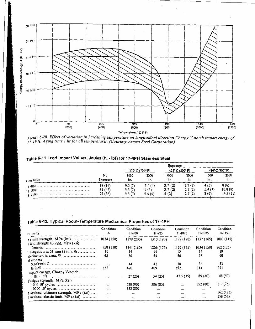
60 ll!lJ) . ·--,---,--,------,---,---,-----,.
7/ll'•il) .---·f----+---1'------i-------l--_J ___ J_ __ _
''!.,~----~----igs< _____ J-__ •2*-os~--L---,3,hs---L------,,d3or---~--~s,~o--~--~so (200) (400) (600) (800) (1000) (1200)
Temperature. •c (° F)
!"Wifi' 6-20 .. Effect of variation in hardening temperature on longitudinal direction Charpy V-notch impact energy of 1 ' .J/'H. Agmg tzme I hr for all temperatures. (Courtesy Armco Steel Corporation)
rullie 6-11. lzod Impact Values, Joules (It· lbl) lor 17-4PH Stainless Steel
E:c.posure
llO'C (700' F) 425' c (800° F) 480' c c9oo• F)
No 1000 2000 1000 2000 1000 2000
1 11111 1~tion E:..posure hr. hr. hr. hr. hr. hr.
II •JOO ...... .............................. 19 ( 14) 9.5 (7) 5.4 (4) 2.7 (2) 2.7 (2) 4 (3) 8 (6)
11 111110 ................................... 61 ( 45) 9.5 (7) 4 (3) 2.7 (2) 2. 7 (2) 5.4 (4) 10.8 (8)
tl 11110 ................................... 76 (56) 9.5 (7) 5.4 (4) 4 (3) 2. 7 (2) 8 (6) 14.9(11)
rable 6-12. Typical Room-Temperature Mechanical Properties o117-4PH
Condition Condition Condition Condition Condition Condition
l't11pcrty A H-900 H-925 H-1025 H-1075 H-1150
1 ensile strength, MPa (ksi) ................. 1034(150) 1379 (200) 1310 (190) 1172 (170) 1137 (165) 1000 (145) 1 1dd strength (0.2%), MPa (ksi)
Tension ................................... 758 (110) 1241 (180) 1206 (175) 1137 (165) 1034 (150) 862 (125) t•lungation in 51 mm (2 in.),% ............. 10 14 14 15 16 19 Hcduction in area,% ....................... 45 50 54 56 58 60 t 1 ardness
Rockwell C ............................... 44 42 38 36 33 Brinell ..................................... 332 420 409 352 341 311
tulpact energy, Charpy V-notch, J (ft.. lbf) ................................. 27 (20) 34 (25) 47.5 (35) 89 (40) 68 (50)
t'atigue strength, MPa (ksi) tO X 106 cycles ............................ 620 (90) 586 (85) 552 (80) 517 (75) tOO X tO' cycles .......................... 552 (80)
rnrsional ultimate strength, MPa {ksi) ... 862 (125) rorsional elastic limit, MPa (ksi) .......... 358 (52)
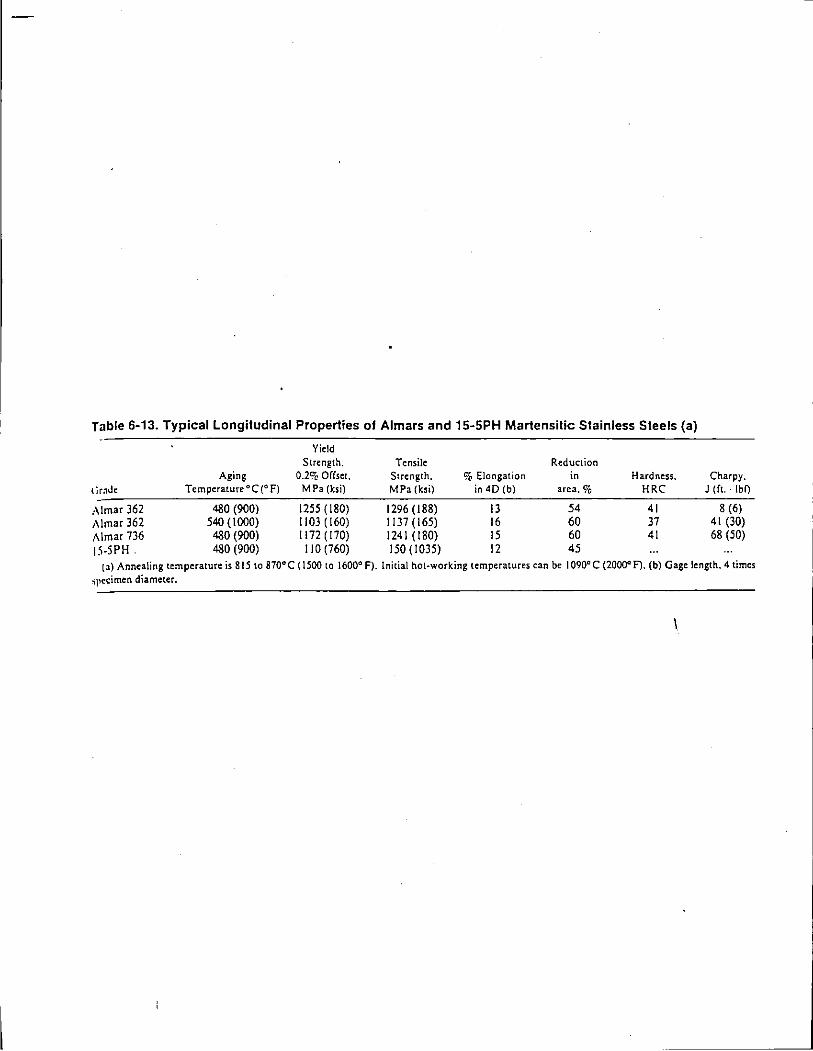
Table 6-13. Typical Longitudinal Properties of Almars and 15-SPH Martensitic Stainless Steels (a)
Yield Strength. Tensile Reduction
Aging 0.2% Offset. Strength, % Elongation in Hardness. Charpy. t iraJe Temperature oc (0 f) MPa (ksi) MPa (ksi) in 40 (b) area,% HRC J (ft.. lb0
,\lmar 362 480 (900) 1255 (180) 1296 ( 188) 13 54 41 8 (6) i\lmar 362 540 ( 1000) 1103 (160) 1137 (165) 16 60 37 41 (30) Almar 736 480 (900) 1172 (170) 1241 (180) 15 60 41 68 (50)
15-SPH. 480 (900) 110 (760) 150(1035) 12 45
(a) Annealing temperature is 815 to 870°C ( 1500 to 1600° f). Initial hot~working temperatures can be I 090° C (20000 F). (b) Gage length. 4 times 'iJlcdmen diameter.
I
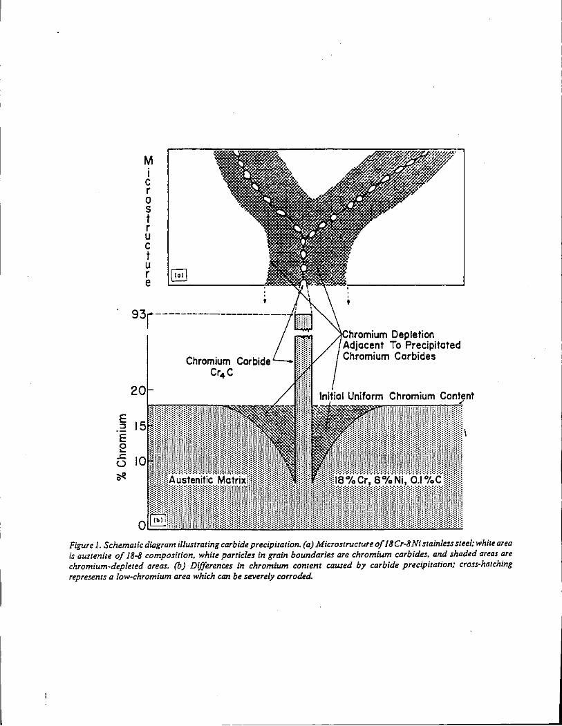
E ::s E e
...:: (.)
~
M I c r 0 s f r u c f u r e
93r
20
[§]
Chromium Carbide Cr4 C
':\Chrr1mium Depletion Adjacent To Precipitated Chromium Carbides
Figure 1. Schematic dillgram illustrating carbide precipitation. (a) Microstructure of 18Cr-8Ni stainless steel; white area is austenite of 18-8 composition. white particles in grain boundaries are chromium carbides. and shaded areas are chromium-depleted areas. (b) Differences in chromium content caused by carbide precipitation; cross-hatching represents a low-chromium area which can be severely corroded.
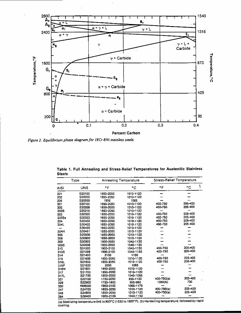
u. 0
.; -:I ;; -.. c. E .. ....
2800 A, Az
2400
1600
G,
·~ 800
200
I I I I T I I I I I
F:;:-a+L a
~ i;t," HI a+"'+L --a+'Y J,
~ Hz 7
1- -------1- ---- - 'Y + Carbide
s, _a -------- s + -2
-'Y a + 'Y + Carbide ...... "' a ----------Pz
. a+ Carbide
a, I I I I ' I ' I
0 0.1 0.2
Percent Carbon
Figure 2. Equilibrium phase diagram/or 18Cr·8Ni stainless steels.
I I I I I I 1540
a, .-y+L
E, 1315 . ........_ -.... 'Y+L+
Carbide -
-870
---
425
--
- 95 I I I I I I
0.3 0.4
Table 1. Full Annealing and Stress-Relief Temperatures lor Austenitic Stainless Steels
Type Annealing Temperature Stress-Relief Temperature
A lSI UNS op oc op oc 201 520100 1850-2050 1010-1120 202 520200 1850-2050 1010-1120 205 520500 1950 1065 301 530100 1850-2050 1010-1120 400-750 205-400 302 530200 1850-2050 1010-1120 400-750 205-400 3028 530215 1850-2050 1010-1120 303 530300 1850-2050 1010-1120 400-750 205-400 3035e 530323 1850-2050 1010-1120 400-750 205-400 304 530400 1850-2050 1010-1120 400-750 205-400 304L 530403 1850-2050 1010-1120 400-750 205-400
530403 1850-2050 1010-1120 304N 530451 1850-2050 1010-1120 305 520500 1850-2050 1010-1120 308 530800 1850-2050 1010-1120 309 530900 1900-2050 1040-1120 3095 530908 1900-2050 1040-1120 310 531000 1900-2100 1040-1150 400-750 205-400 3105 521008 1900-2100 1040-1150 400-750 205-400 314 521400 2100 1150 316 521600 1850-2050 1010-1120 400-750 205-400 316L 521603 1850-2050 1010-1120 400-750 205-400 316F 521620 2000 1095 316N 521651 1850-2050 1010-1120 317 531700 1850-2050 1010-1120 317L 531703 1900-2000 1040-1095 321 532100 1750-2050 855-1120 400-750(a) 205-400
329 532900 1750-1800 955-980 1350(b) 730 330 N08330 1950-2150 1065-1175 347 524700 1850-2050 1010-1120 400-750(a) 205-400 348 534800 1850-2050 1010-1120 400-750(a) 205-400
384 538400 1900-2100 1040-1150
{a) Stablizing temperature 845 to 900°C (1550 to 165011 F). (b) Harden'ing temperature, to/lowed by rapid cooling.
-i .. 3 ., .. ~
" 2' ~
~ 0
(')
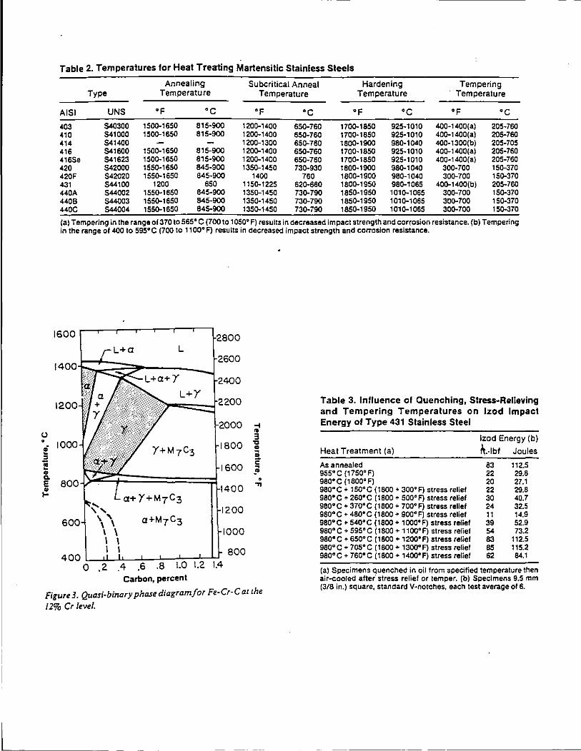
u • ! ::1 e .. c. E ~
Table 2. Temperatures for Heal Treating Martensilic Stainless Steels
Annealing Subcritical Anneal Hardening Tempering Type Temperature Temperature Temperature Temperature
A lSI UNS "F ·c "F ·c "F •c "F •c 403 540300 150Q-1650 815-900 120Q-1400 650-760 170Q-1850 925-1010 400-1400(a) 205-760 410 541000 150Q-1650 815-900 120Q-1400 650-760 170Q-1850 925-1010 40Q-1400(a) 205-760 414 541400 1200-1300 65Q-760 1800-1900 980-1040 400-1300(b) 205-705 416 541600 150D-1650 815-900 120Q-1400 650-760 1700-1850 925-1010 40D-1400(a) 205-760 4165e 541623 150D-1650 815-900 120Q-1400 65D-760 170D-1850 925-1010 400-1400(a) 205-760 420 542000 155Q-1650 845-900 135D-1450 730-930 180D-1900 98Q-1040 30D-700 15Q-370 420F 542020 155D-1650 845-900 1400 760 1800-1900 980-1040 30D-700 15Q-370 431 544100 1200 650 115Q-1225 62Q-660 1800-1950 98Q-1065 40Q-1400(b) 205-760 440A 544002 155D-1650 845-900 1350-1450 73Q-790 1850-1950 101Q-1065 30Q-700 15Q-370 4408 544003 155Q-1650 845-900 135Q-1450 730-790 1850-1950 101Q-1065 30D-700 15Q-370 440C 544004 155Q-1650 845-900 135Q-1450 73Q-790 1850-1950 1010-1065 300-700 150-370
(a) Tempering in the range of 370 to sss• C (700 to 1050° F) results in decreased impact strength and corrosion resistance. (b) Tempering in the range of 400 to 595 111 C (700 to 1100•F) results in decreased impact strength and corrosion resistance.
1600
Carbon, percent
~ .. 3 ., .. ; 2' ~ • .,
Table 3. Influence of Quenching, Stress-Relieving and Tempering Temperatures on lzod Impact Energy of Type 431 Stainless Steel
Heat Treatment (a)
As annealed 955"C (1750"F) 98o·c (1800"Fl sso•c + 1so•c (1800 + 30011 F) stress relief 980'" C + 260° C ( 1800 + 500° F) stress relief 980°C + 370°C (1800 + 700°F) stress relief 980°C + 480°C (1800 + 900°F) stress relief 980° C + 540° C ( 1800 + 1000° F) stress relief sso•c + sssoc (1800 + 1100°F) stress relief sso•c +- ssooc (1800 + 1200°F) stress relief 980°C + 705°C (1800 + 1300°F) stress relief 980°C + 760°C (1800 + 1400°F) stress relief
lzod Energy (b)
~.·lbf Joules
S3 22 20 22 30 24 11 39 54 83 85 62
112.5 29.8 27.1 29.8 40.7 32.5 14.9 52.9 73.2
112.5 115.2 84.1
Fii{Ure 3. Quasi-binary phase diagram for Fe-Cr-C at the
I 2% Cr level.
(a) Specimens quenched in oil from specified temperature then air-cooled after' stress relief or temper. (b) Specimens 9.5 mm (3/8 in.) square, standard V-notches, each test average or 6.
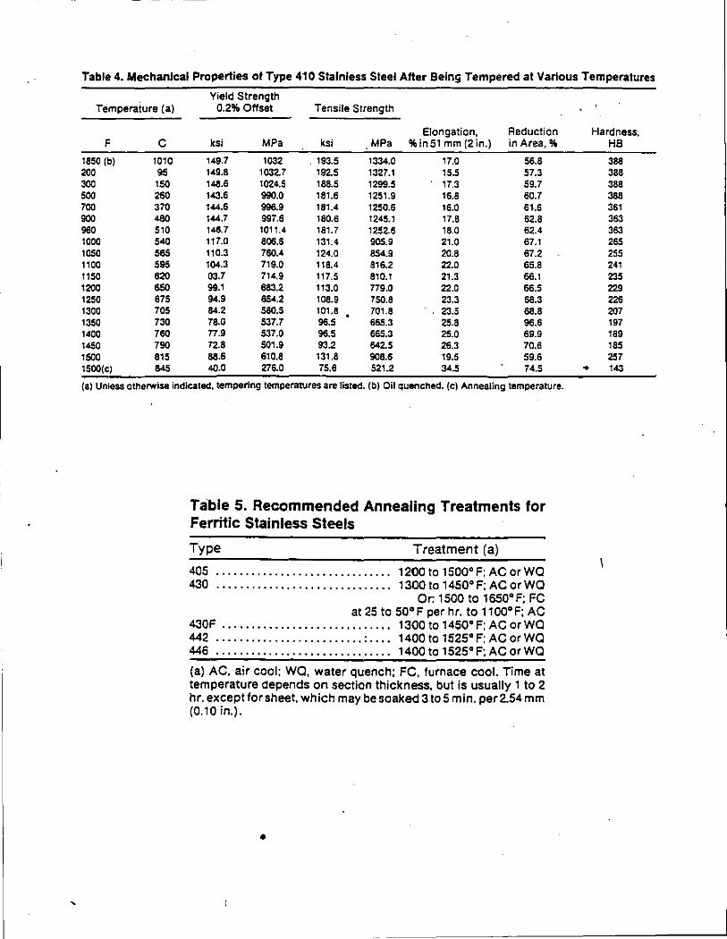
'
-------------
Table 4. Mechanical Properties of Type 410 Stainless Steel After Being Tempered at Various Temperatures
Yield Strength Temperature (a) 0.2% Offset Tensile Strength
Elongation, Reduction F c ksi MPa ksi MPa %in 51 mm (2 in.) in Area,%
1850 (b) 1010 149.7 1032 . 193.5 1334.0 17.0 56.8 200 95 149.8 1032.7 192.5 1327.1 15.5 57.3 300 150 148.6 1024.5 188.5 1299.5 17.3 59.7 500 260 143.6 990.0 181.6 1251.9 16.8 60.7 700 370 144.6 996.9 181.4 1250.6 16.0 61.6 900 480 144.7 997.6 180.6 1245.1 17.8 62.8 960 510 148.7 1011.4 181.7 1252.6 18.0 62.4 1000 540 117.0 806.6 131.4 905.9 21.0 67.1 1050 565 110.3 760.4 124.0 854.9 20.8 87.2 1100 595 104.3 719.0 118.4 816.2 22.0 65.8 1150 620 03.7 714.9 117.5 810.1 21.3 66.1 1200 650 99.1 683.2 113.0 n9.o 22.0 66.5 1250 675 94.9 654.2 108.9 750.8 23.3 66.3 1300 705 84.2 580.5 101.8 701.8 23.5 88.8 1350 730 78.0 537.7 96.5 665.3 25.8 96.6 1400 760 n.9 537.0 96.5 665.3 25.0 69.9 1450 790 72.8 501.9 93.2 642.5 26.3 70.6 1500 815 88.6 610.8 131.8 908.6 19.5 59.6 1500(cl 845 40.0 276.0 75.6 521.2 34.5 74.5
(a) Unless otherwise indicated, tempering temperatures are listed. (b) Oil quenched. (c) Annealing temperature.
Table 5. Recommended Annealing Treatments for Ferritic Stainless Steels
Type Treatment (a)
405 .............................. 1200to1500°F;ACorWQ 430 .............................. 1300to14SO•F;ACorWQ
Or: 1500 to 1sso• F; FC at 25 to so• F per hr. to 11oo•F: AC
430F ............................. 1300to14SO•F;ACorWQ 442 ......................... : .... 1400to1525°F;ACorWQ 446 .............................. 1400 to 152s•F; AC orWQ
(a) AC, air cool: WQ, water quench; FC, furnace cool. Time at temperature depends on section thickness, but is usually 1 to 2 hr. exceptforsheet. which may be soaked 3to5 min. per2.54 mm (0.10 in.).
•
Hardness, HB
388 388 388 388 361 363 363 265 255 241 235 229 226 207 197 189 185 257
• 143
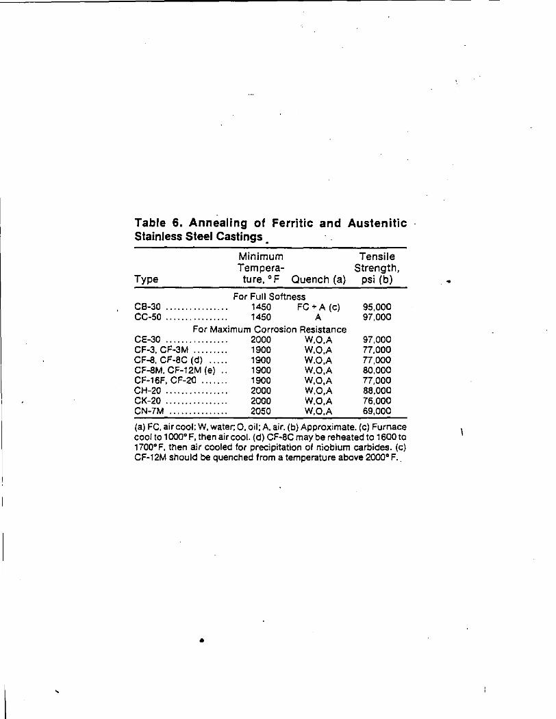
'
Table 6. Annealing of Ferritic and Austenitic Stainless Steel Castings
Type
Minimum Tempera-ture, • F Quench (a)
For Full Softness CB-30 .. . . . .. . . .. .. . . . 1450 FC +A (c) CC-50 . . . . . . . . . . . . . . . . 1450 A
For Maximum Corrosion Resistance CE-30 . . . . . . . . . . . . . . . . 2000 W.O.A CF-3, CF-3M .. .. .. ... 1900 W,O,A CF-8, CF-8C (d) .. .. . 1900 W,O,A CF-8M, CF-12M (e) .. 1900 W,O,A CF-16F, CF-20 .... .. . 1900 W,O,A CH-20 .. .. .. .. . .. .. .. . 2000 W,O,A CK-20 .. .. .. .. .. .. .. .. 2000 W,O,A CN-7M .. .. . .. .. .. .. .. 2050 W,O,A
Tensile Strength,
psi (b)
95,000 97,000
97,000 77,000 77,000 80,000 77,000 88,000 76,000 69,000
(a) FC. air cool: W, water; 0, oil; A, air. (b) Approximate. (c) Furnace cool to 1000• F, then air cool. (d) CF-8C maybe reheated to 1600 to 1700° F, then air cooled for precipitation of niobium carbides. (c) CF-12M should be quenched from a temperature above 2000• F ..
•
•
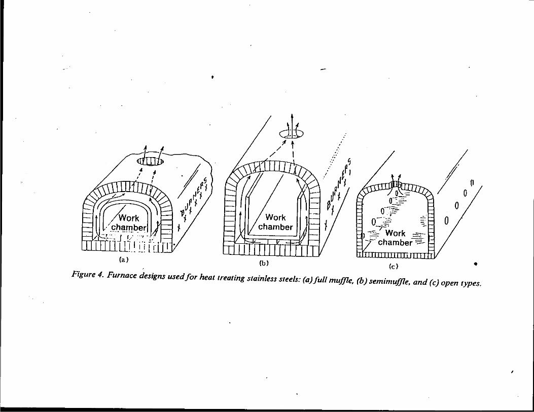
•
Jb /t
/ I
(a) (b)
· . .. .. ~
_,. .... /) l1
~~ j
0 ::: 0~.:.::
o- .· ,=-.. o+~· -
1 -:c: Work -~ --·chamber-:::-
(c)
0
• Figure 4. Furnace designs used for heat treating stainless steels: (a)full muffle, (b) semimufJle, and (c) open types.
,
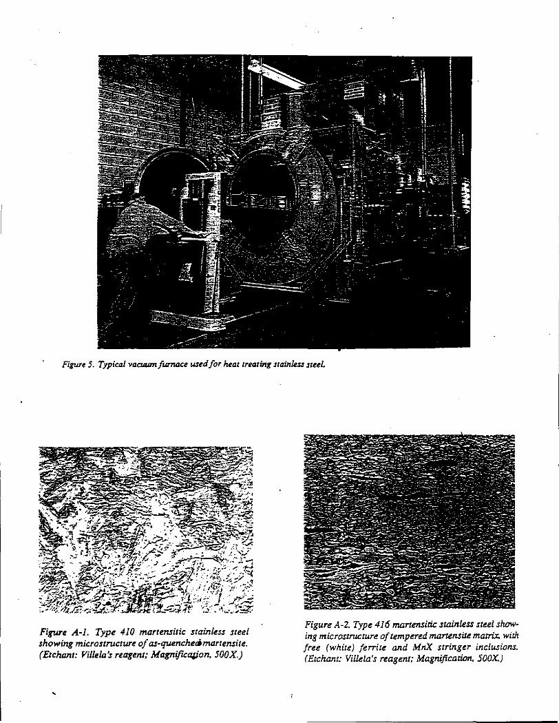
Figure 5. Typical vacuum furnace wed for heattrealinlf stainkss steel.
-. . /, .~ .... .. ~-"~ ~~/ .-t
"',!!\ ·;-:-:";
~··_;. • ~:,.,,;-<
~)"~.:..·.--'~
Figure A-1. Type 410 martensitic stainless steel showing microstructure of as-quenchecjmartensite. (Etchant: Villela's reagent; MagnificaJjon, 500X.)
'
Figure A-2. Type 416 martensitic slllinless steel showing microstructure of tempered martensite matrix. with free (white) ferrite and MnX stringer inclusions. (Etchant: Villela's reagent; Magnification, 500X)
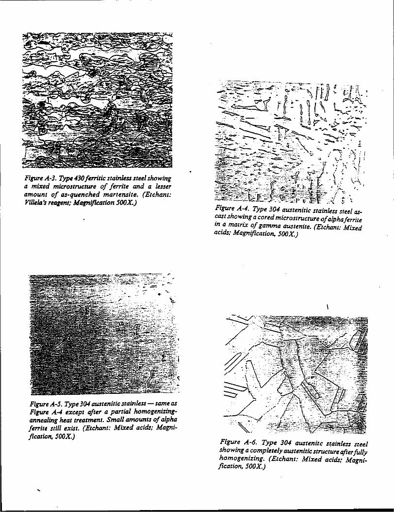
Figure A-3. Type430feTTitic stainless steel showing a mixed microstructuTe of ferrite and a lesser amount of as-quenched martensite. (Etchant: Villela's reqent; Magnification 500X.)
Figure A-S. Type 304 austenitic stainless- sa':'~ as Figure A-4 except after a partial homogeniZITigannealing heat treatment. Small amo~ts of a/ph~ fe"ite still exist. (Etchant: Mixed aczds; Magnzjication, 500X.)
Figure A-6. Type 304 austenite s(ainless steel showing a completely austenitic structure after fully homogenizing. (Etchant: Mixed acids; Magnification, 500X.)
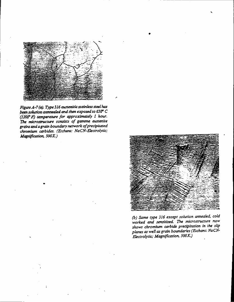
Figpr.e A"7(.aj). Type 316 au-stenitic stainless steel has /:i"en fO/Jzpiol!. annnetiled and then exposed 10 6511' C (12000 F;) temperature far approximately l hour. The microsuw:ture consists of gtzmmll austenite grtlinsand a grain bo.Wtdary network of precipitated chromium carbides. (Etchant: NaCN-Electrolytic; Magnification, SOOX.)
•
. •
'
•
(b) Same type 316 except solution annealed, cold worked and sensitized. The microstructure now shows chromium carbide precipitation in the slip planes as well as grain boWtdaries (Etchant: NaCNElectrolytic; Magnification, SOOX.)
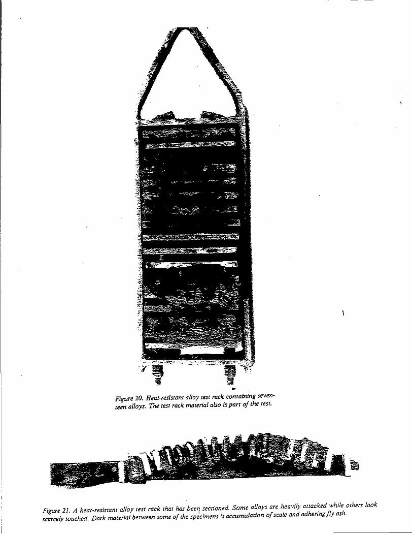
.. Figure 20. Heat-resistant alloy test rack containing seven· teen alloys. The test rack material also is part of the test.
Figure 21. A heat-resistanr alloy test rack that has beery sectioned. Some alloys are heavily attacked while others look scarcely touched. Dark material between some of the specimens is accumulation of scale and adhering fly ash.
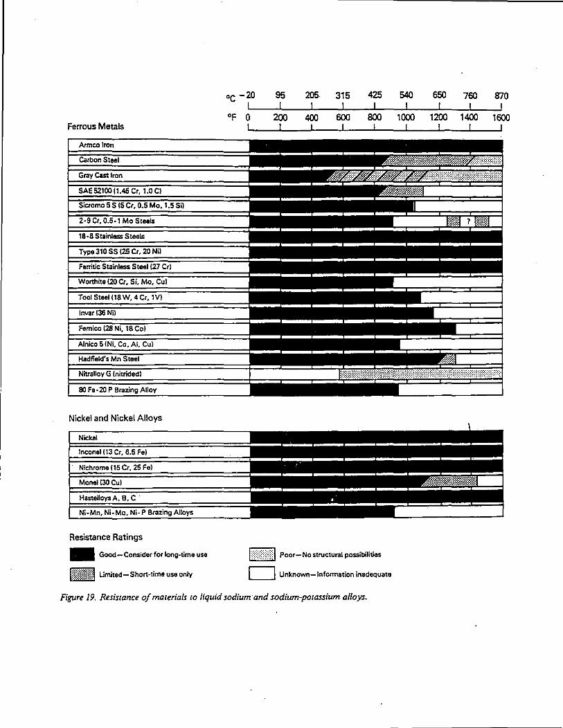
Ferrous Metals
Nickel and Nickel Alloys
Resistance Ratings
- Good-Consider for long-time use
M~1{~1\ Umited-Short-time use only
oc -20
°F 0
95 205. 315 425
j}~}j{J Poor- No structural possibilities
D Unknown-Information inadequate
Figure 19. Resistance of materials to liquid sodium and sodium-potassium alloys.
540 650 7f'IJ 870
1f'IJO
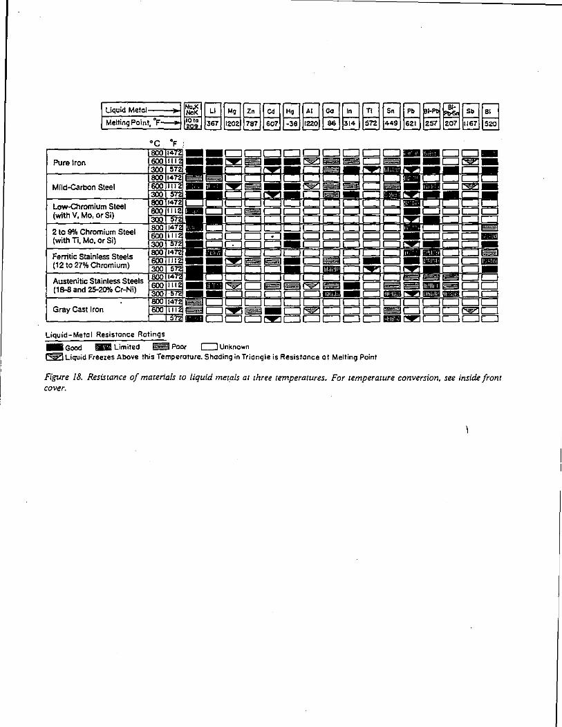
Pure Iron
Mild-carbon Steel
Low-Chromium Steel (with V, Mo, or Si)
2 to 9% Chromium Steel (with Ti, Mo, or Si)
Fenitic Stainless Steels (12 to 27% Chromium)
Austenitic Stainless Steels (1 8-8 and 25-20o/o Cr-Ni)
Gray Cast Iron
Liquid-Metal Resistance Ratings
-Good 1E11 Limited ~Poor c:::J Unknown ~Liquid Freezes Above this Temperature. Shading in Triangle is Resistance at Melting Point
Figure 18. Resistance of materials ro liquid met_als at three temperatures. For temperature conversion, see inside front cover.
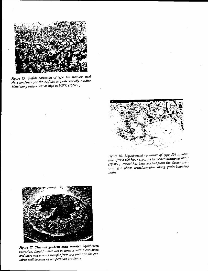
Figure 15. Sulfide corrosion of rype 310 srainless sreel. Nore rendency for rhe sulfides ro preferenrially oxidize. Meralremperarure was as high as 9000C (165C1'F).
Figure 17. Thermal gradienr mass rransfer liquid-meral corrosion. Liquid metal was in contact with a container, and rhere was a mass rransfer from hor areas on rhe conrainer wall because of remperarure gradienrs.
.. :-&..-:::;· - :~/·
Figure I 6. Liquid-meral corrosion of rype 304 srain/ess sreel afrer a 400-hour exposure 10 molren /irhiu'Vt ar 98C1'C (180(1' F). Nickel has been leached from rhe ddrker areas causing a phase rransformarion along grain-boundary
parhs.
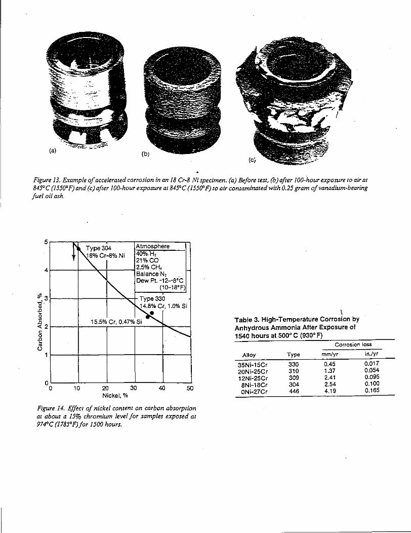
Figure I 3. £~ample of accelerated corrosion in an I 8 Cr-8 Ni specimen. (a) Before test, (b) after /00-hour exposure to air at 845°C (I5500F)and (c) after IOO-hour exposure at 845°C (/5500F) to air contaminated with 0.25 gram of vanadium-bearing fuel oil ash.
5
4
#3 ~·-·
" .c 0 "' .c <(2 c: 0 .c ~
(.)
1
() ()
Type304 Atmosphere
~Cr-8%Ni 40%.H, -·
21%CO 2.5% CH,
'\ Balance:N,
""' Dew Pt. ·12-·S'C
(1Cl-18'F)
Type330
...... ~r, 1.0% Si
15.5% Cr, 0.47% Si e
~
10 20 30 40 50 Nickel,%
Figure /4. Effect of nickel content on carbon absorption at about a I5% chromium level for samples exposed at 97~C (/785°F)for I 500 hours.
I Table 3. High-Temperature Corrosion by Anhydrous Ammonia After Exposure of 1540 hours at 500° C (930' F)
Corrosion loss
Alloy Type mm/yr in./yr
35Ni-15Cr 330 0.45 0.017 20Ni·25Cr 310 1.37 0.054 12Ni-25Cr 309 2.41 0.095 8Ni-18Cr 304 2.54 0.100 ONi·27Cr 446 4.19 0.165
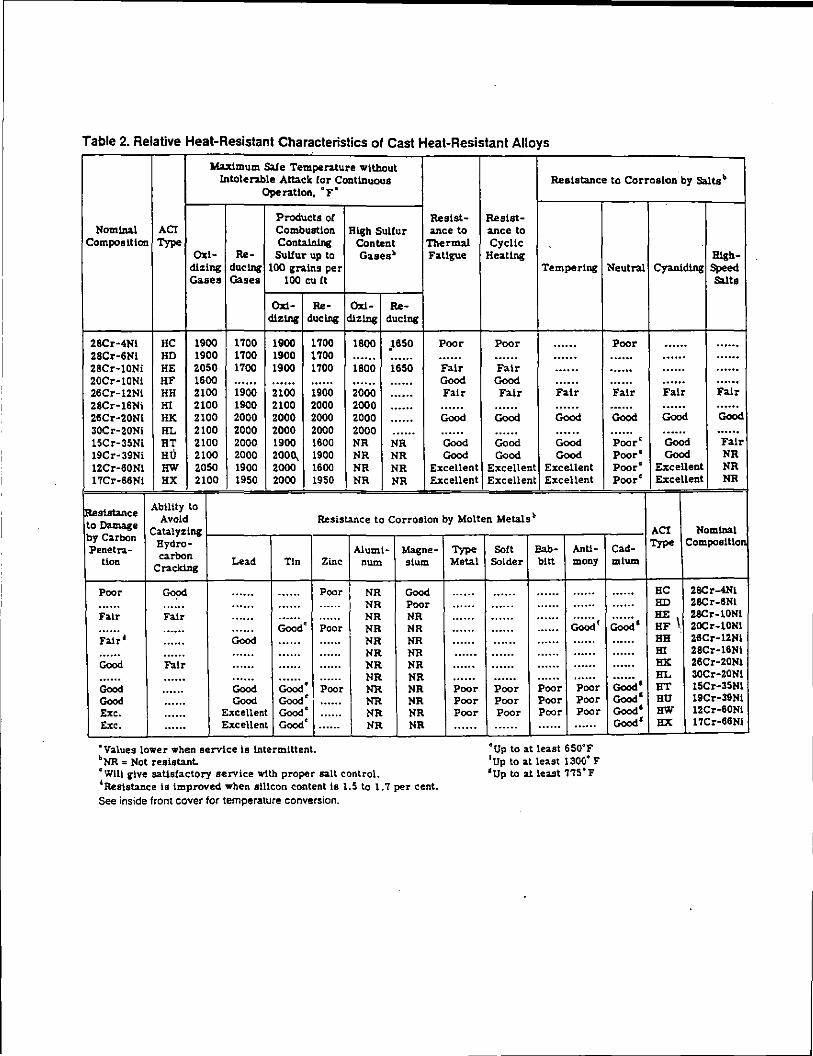
Table 2. Relative Heat-Resistant Characteristics of Cast Heat-Resistant Alloys
Maximum Safe Temperature wtthout Intolen.ble Attack lor Continuous Reaiata.Dce to Corrosion by Salta'-
Ope ration, • F •
Products ol Resist- Resist-Nominal AC! Combustion Hlib Sulfur ance to ance to
Composttton Type ConWnlng Content Thermal Cyclic Ox!- RA!- Sullur up to Gasesb Fatigue Heating
di:ing duclng 100 grains per Tempering Gases Gases 100 cult
Ox!- RA!- Ox!- RA!-dlzlng duclng dlzlng duclng
28Cr·4!11 HC 1900 1700 1900 1700 1800 .1850 Poor Poor ...... 28Cr-6!11 HD 1900 1700 1900 1700 ...... ...... ...... . ..... ...... 28Cr·10!1i HE 2050 1700 1900 1700 1800 1650 Fair Fatr ...... 20Cr·10!11 HF 1600 ...... ...... ...... ...... .. .... Good Good ...... 26Cr-12!1i HH 2100 1900 2100 1900 2000 ...... Fair Fair Fair 28Cr·16!11 HI 2100 1900 2100 2000 2000 ...... ...... . ..... ...... 26Cr·20!11 HK 2100 2000 2000 2000 2000 ...... Good Good Good 30Cr-20!11 HL 2100 2000 2000 2000 2000 ...... ...... ...... ...... 15Cr-35!1i HT 2100 2000 1900 1600 !IH !IR Good Gcod Good 19Cr·39!1i HU 2100 2000 2ooo_ 1900 !IR !IR Good Gcod Good 12Cr-60!11 HW 2050 1900 2000 1600 !IR !IR Excellent Excellent Excellent 17Cr-86!11 HX 2100 1950 2000 1950 !IR !IR Excellent Excellent Excellent
Ability to fReslstance Avoid Resistance to Corrosion by Molten Metals b to Damage Catalyzing by Carbon Hydro-Penetra-
carbon tion Cracking
Lead Tin
Poor Gcod ...... ...... ...... ...... ...... .. .... Fair Fair ...... ...... ...... ··-··· ...... Good' Fair• ...... Gcod ...... ...... ...... ...... ...... Gcod Fair ...... ...... ...... ...... ...... Gcod ...... Gcod ~e Gcod ...... Gcod Gcod' Ex c. ...... Excellent Gcod' Exc. ...... Excellent Good'
·values lower when service is intermittent. bNR = Not resistant.
Aluml- Magne-Zinc num sium
Poor !IR Gcod .. .... !IR Poor ...... !IR NR Poor !IR !IR .. .... !IR !IR ...... !IR !IR ...... !IR !IR . ..... !IR !IR Poor !IR !IR ...... IIR !IR .. .... !IR !IR ...... !IR !IR
cWill give satisfactory service with proper salt control. dReststance is improved when stucon content is 1.5 to 1.7 per cent. See inside front cover for temperature conversion.
Type Metal
.. ....
......
......
......
...... ...... ...... . ..... Poor Poor Poor .. ....
Soft Bab- AnU· Solder bitt many
...... .. .... ...... ...... ...... ...... . ..... .. .... Gc;;;d f .. .... ...... ...... ...... ...... .. .... .. .... ...... ...... .. .... ...... . ..... ...... ...... Poor Poor Poor Poor Poor Poor Poor Poor Poor ...... ...... .. ....
•up to at least 6so•F 1Up to at least 130/j• F •up to at least 7'75 • F
111gb-Neutral Cyaniding Speed
Salta
Poor ...... ...... ...... ...... ...... ...... ...... ...... . ..... ...... ...... Fair Fair Fair .. .... ...... ...... Good Good Good .. .... ...... ...... Poore Good Fair Poore Good IIR Poore Excellent !IR Poore Excellent !IR
ACI Nominal
Cad· Type Composltlo'
mlum
...... BC 28Cr-4111
...... BD 28Cr-8!11
Gc;;;d. BE 28Cr-1DNI BF \ 20Cr-1DNI
...... BB 26Cr-12!11
...... Bl 28Cr-16!11
...... HK 28Cr-20!11
~· BL 30Cr·ZO!Il BT 15Cr-35!11
Gcod' BU 19Cr-39!11 Good' HW 12Cr-80!11 Gcod' BX 17Cr-88!11
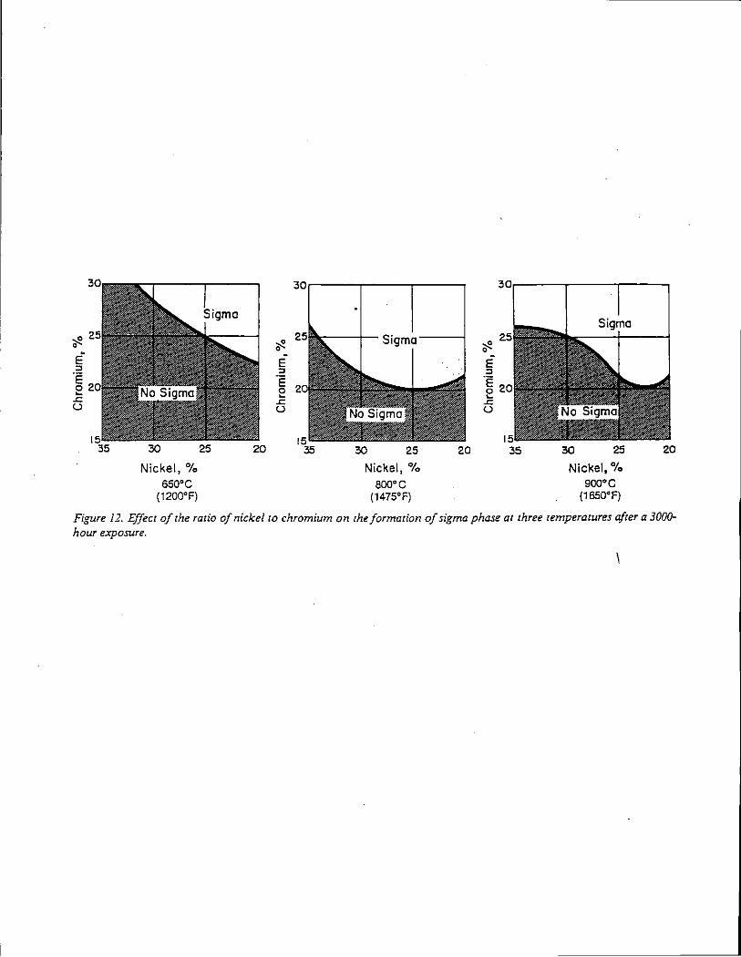
Nickel,% sso•c
(1200'F)
E " .E 2 .<: u
Nickel,% aoo•c
(1475'F)
E " .E 2
.<: u
25
Nickel,% eoo•c
(1650'F)
20
Figure 12. Effect of the ratio of nickel to chromium on the formation of sigma phase at three temperatures after a 3000-hour exposure.
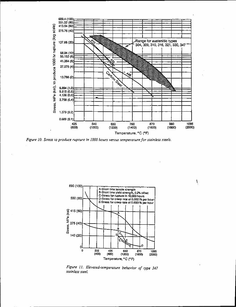
.., ... u
"' Ol .2
425 (800)
540 (1000)
650 (1200)
760 (1400)
austenitic types 310,316,321,330,347
870 (1600)
980 (1800)
1095 (2000)
Temperature, 'C ('F)
Figure 10. Stress to produce rupture in 1000 hours versus temperature for stainless steels.
690 (1 OO)IT---r-:-:::--:c---::-~~~~~-, A-Sho/1 time tensile strength
\ 8-Short time yield strength. 0.2% offset ~ C-Stress for rupture in 10,000 hours
550 {BO}t--'<1--+D-Stress for creep rate of 0.0001'/a per hour ~ E-Stress for creep rate of 0.0001% per hour
'iii 415 (60JI--t-t~'--~~F:::-t-' -+--+----11-+-l :_ I -......A
~ "' ~ 275 ( 40) 1\.
~ -1-t--+-~8- \" en D c:-'-- - ...,_
140 (20)1-+-t~+-+- 1<;~ 'f--1-1 -===-~ct-~
:~ "r--~-E,.,_ __ D
0~~~-L-=~~~~~_L~ 0 205 425 650 870 1095
(400) (800) (1200) (1600) (2000)
Temperature, 'C ('F)
Figure /1. Elevated-temperature behavior of type 347 stainless steel.
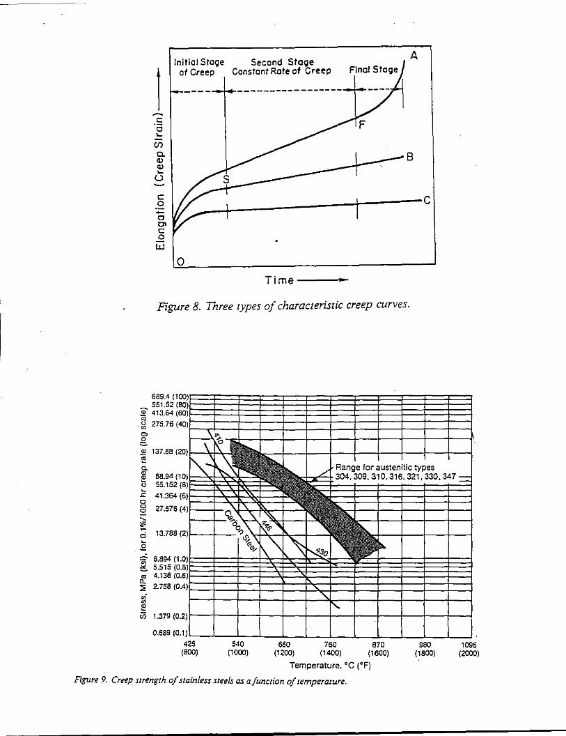
Initial Stege Second StoQe A
1
I of Creep Constant Rote of Creep
~----~-----------------
~
.s c ....
U'l
~I I ~ I ~s ., .... u ~
-~ 1// -c 0> c 0
w I
0
Time
Figure 8. Three types of characteristic creep curves.
'100) 689.4 - 551.52 ~ 413.64
"' ~ 275.76 0> g 2 137.88 1:
(80) (80)
(40)
c
a. Range for austenitic types ~ 68.94 t 55.15
'10) 304,309,310,316.321,330,347 = (B)
.c: 41.364 0
(6)
g 27.57 (4) -.._ "' • d 13.78· (2) ~
.£ 'iii 6.894 "'- 5.515 ttl 4.136 a. ::;; 2.758 .,; "' e (ij 1.379
0.689
i.O) (0.8) (0.6)
(0.4)
(0.2)
{0.1!
425 (800)
540 (1000)
650 (1200)
760 (1400)
870 (1600)
Temperature. 'C ('F)
Figure 9. Creep strength of stainless steels as a function of temperature.
980 (1800)
1095 (2000)
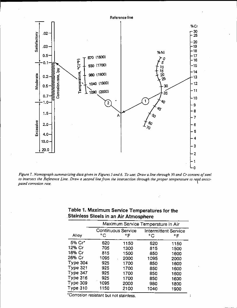
~ .02 0 -0
"' -.!!! .03 ;,; IJl
0.5
0.1
" - 0.2 .,· I!! -I!! " "C c: 0 0.5 0
::iE 'iii 0 --0.7 0 u
1.0
1.5
" > 2.0 ·;;; Ul ., 0 X 4.0 w
10.0
u: 0
u 0
.,· :; -ca
~' E " 1-
870 (16001
930 (17001
980 (16001
1040 ( 19001 ......_
1090 (20001
Reference line
%Ni
30
35
%Cr 30 25
20 19 18 17 16
15
14 13
12
11
10
9
8
7
6
5
4
3
2
1
0
Figure 7. Nomograph summarizing data given in Figures 5 and 6. To use: Draw a line through Ni and Cr content of steel to intersect the Reference Line. Draw a second line from the intersection through the proper temperature lO re\d anticipated corrosion rate.
Table 1. Maximum Service Temperatures for the .Stainless Steels in an Air Atmosphere
Maximum Service Temperature in Air
Alloy
5% cr· 12% Cr 18% Cr 26% Cr Type 304 Type 321 Type 347 Type 316 Type 309 Type 310
Continuous Service oc °F
620 705 815
1095 925 925 925 925
1095 1150
1150 1300 1500 2000 1700 1700 1700 1700 2000 2100
·corrosion resistant but not stainless.
Intermittent Service oc °F
620 815 850
1095 850 850 850 850 980
1040
1150 1500 1600 2000 1600 1600 1600 1600 1800 1900
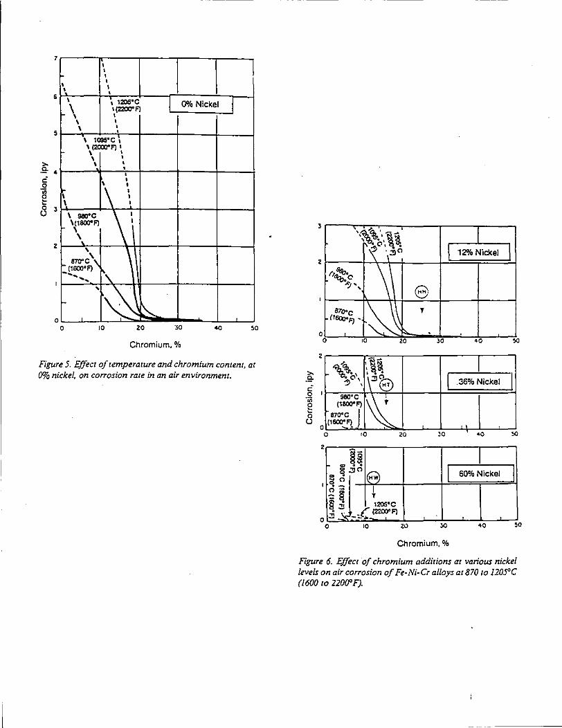
7
6
5
,.. .e- 4
g g 8 3
2
I
0
I I I
I I
I I I
\ , 120S•c I 0% Nickel 1 f-\ I 1220Q"F} I
\ I
\ I
• ' 1css•c , \ (200Q"F} I \ . \ . \ .
• • I
1,- [\ I I
\ I I I
1 sao·c \\ 1(1800"F} \ '.
\ \ 870"C\ (1600"F}
~\. ------ '·~
~ 0 10 zo 50
Chromium,%
Fi~re 5. Effect of temperature and chromium content, at 0% nickel, on corrosion rate in an air environment.
,.. ,g.
" 0 ·;;; g 0 (J
3
\~~ .. r ' • . '& ~o. •
2 ·,~"
r,:;;:.c ~ .. , \\
B7ooc f. (I<QooF) •
0 0
• l~
10
z --.,-q. ',~~ ~~., 1\~n "'!>"\ e
1
sao·c [~ (1800'F} '
870"C J (1800"F}
0 -0 10
2
~~ ~ .. g .:;JCI lA '" ~ 0
I ~ -. 0--:: 8 §.:!5 .:!i..s. 0
0
I T 1205•c
.t. (2200" F) __ ..,
10
20
20
20
\ 12% Nickel \
e '
->O <0
I .36% Nickel
JO •a
I 60% Nickel
>0 40
Chromium,%
"'
I
"'
I
50
Figure 6. Effect of chromium additions at various nickel levels on air co"osion of Fe-Ni-Cr alloys at870 to I205°C (I 600 to 22000 F).
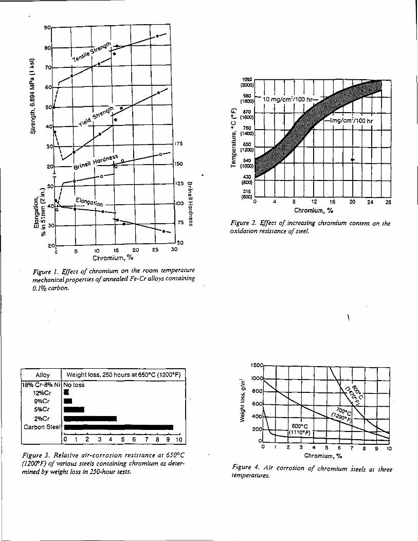
I I I I 1 ... --1 \ ,~ L---<;:,\<•«"- !--"'
tf,\l.e • ~ef' •/
90
eo
0 v 0
r I ,.../ I / I
0 ~'t\~ S''e~
0 ~\~.'6 •
~ l,./ I / 0 I
I , .... 3
v .. 'rlo•a"• ~ l--- l"'"o-
2 o1-- e•i"""
,.. I I
~ op
0
0 2 • 0
1-o-
€1ongotion
·-·~·
5 \0 15 20
Chromium, 0/o
-r-._
25
I 75
I 50
I
I
25 CD ~
5" "
00 J: c a. ~
" 75 ::::
50 30
Figure /. Effect of chromium on the room temperature mechanical properries of annealed Fe-Cr alloys containing
0.1% carbon.
Alloy Weight loss, 250 hours at 650'C (1200'F)
18% Cr-8% Ni No loss 12%Cr • 9'A>Cr • 5'A>Cr -2%Cr
Carbon Steel
0 1 2 3 4 5 6 7 8 9 10
Figure 3. Relative air-corrosion resistance at 650°C (1200' F) of various steels containing chromium as determined by weight loss in 250-hour tests.
J15 (600) ~..__-7--'---.':--'-~-'--~--'---'---'---'--'-_J
0 4 6 12 16 20 26
Chromium. 0/o
Figure 2. Effect of increasing chromium content on the oxidation resistance of steel.
Chromium, 0/o
Figure 4. Air corrosion of chromium Steels at three temperatures.
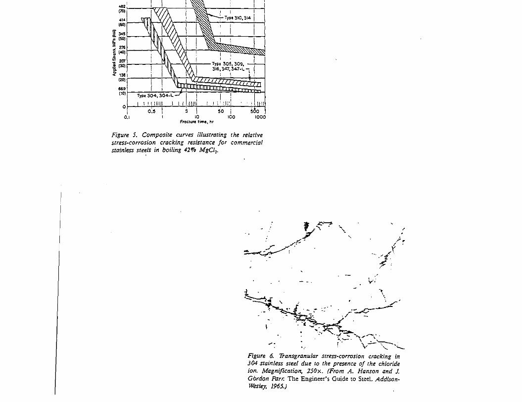
(80) ;--------
0.1 Fracture time, hr
Figure 5. Composite curves illustrating the relative stress~corrasion cracking resistance for commercial stainless steels in boiling 42% MgCI,.
' , ;::--....., ./' . ·,'..
,.... /r-- '• ...... ~--:· - '
y ~~. // ·.
l ~-;
-·_,-~~-.. ' . ·- ·--:....c--,. J ... ~ -. . .I -·
·-' - < ~~ . -~~-
\
- -~-. ~ ~--1 • • - "(....:. "\~ ~"----- ,- \.· '----
Figure 6. Transgranular srress~corrosion cracking in 304 stainless steel due zo che presence of che chloride ion. Magnification, 250x. (From A. Hanson and J. Gbrdon Parr. The Engineer's Guide to Steel. AddisonWesley. 1965.)
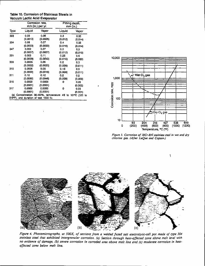
Table 10. Corrosion of Stainless Steels in Vacuum Lactic Acid Evaporator
Corrosion rate, Pitting depth, mm ~n.) per yr. mm ~n.)
Type Liquid Vapor Liquid Vapor
302 0.03 0.05 0.3 0.35 (0.0013) (0.0025) (O.o12) (0.014)
304 0.08 0.07 0.4 0.35 (0.0033) (0.0030) (0.016) (0.014)
347 0.002 0.07 0.3 0.3 (0.0007} (0.0027) (0.012) (0.010)
321 0.003 0.11 0.25 0.5 (0.0009) (O.oo4:J) (O.o10) (0.020)
309 0.0005 0.05 0.2 0.3 (0.0002) (0.0020) (0.008) (0.011)
310 0.0005 0.05 0.15 0.3 (0.0003) (0.0018) (0.006) (0.011)
311 0.12 0.12 0.2 0.2 (0.0050) (0.0048) (0.008) (0.009)
316 0.0003 0.0003 0 0.05 (0.0001) (0.0001) (0.002)
317 0.0003 0.0003 0 0.03 (0.0001) (0.0001) (0.001)
(a) Concentration 30-60%. temperature 49 to 215°F), and duration of test 1000 hr.
101"C (120 to
10,000
1,000
>o c. E .; li! c: 0 100 . ·u; g 0 u
10
<=
I I
I
I I I J \+Wet Cl, gas I I
I
r- .... I I 'ri
I
7"""Tc',sj 93 204 316 427 538 649
0 (200) (400) (600) (800) (1000) (1200) Temperature, "C ('F)
Figure 3. Corrosion of 18Cr-8Ni stainless steel in wet and dry chlorine gas. (After LaQue and Copson.)
Figure 4. Photomicrographs, ac 500)(, of sections from a welded fused salt electrolycic-ce/1 poc made of cype 304 stainless steel chat exhibited incergranular corrosion. (a) Section through heac-ajfecced zone above melt level with no evidence of damage, (b) severe corrosion in corroded area above melt line and (c) moderate corrosion in hearaffected zone below melt line.
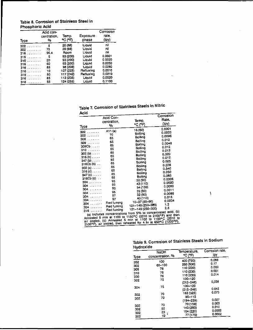
Table 8. Corrosion of Stainless Steel in Phosphoric Acid
Acid con-centration, Temp.
Type % oc ("F)
302 ........ 5 20 (68) 302 ....... 75 20 (68) 316 ...... 90.4 Room
316 ........ 5 93 (200) 316 ........ 20 93 (200) 316 ........ 60 93 (200) 316 ....... 85 98 (208) 316 ... 10 107 (225) 316 ... 50 117 (242) 316 ..... 85 113 (235) 316 ........ 85 124 (255)
Corrosion Exposure rate,
phase (ipy) Uquid nil Liquid nil Liquid nil Liquid 0.0001 Liquid 0.0020 Liquid 0.0050 Uquid 0.0280
Refluxing 0.0010 Refluxing 0.0210
Liquid 0.0520 Liquid 0.1100
Table 7. Corrosion of S1ainless Steels in Nitric
Acid Acid Con 4 Corrosion centration, Temp. Rate,
Type o/o oc (0F) 0PY) 302 .. .. .. . A11 (a) 16 (60) 0.0001 302 . . . . . . . 10 Boiling 0.0003 308 . . . . . . 65 Boiling 0.0096 309 . . . . . . . 65 Boiling 0.012 309Cb . . . . . 65 Boiling 0.0048 310 . . . . . . . 65 Boiling 0.012 302 (b) . . . . . 65 Boiling a .012 316 (b)..... 65 Boiling 0.020 347 (b)..... ss Boiling o.mz 316Cb (b) . . 65 Boiling 0.025 302 (c) . . . . . 65 Boiling 0.228 316 (c) . . . . . 65 Boiling 0.540 347 (c) . . . . . 65 Boiling 0.050 316Cb (c) . . 65 Boiling 0.085 304 .. .. .. . 93 32 (90) 0.0006 304 .. .. . 93 43 (110) 0.0020 304 . . . . . . . 93 54 (130) 0.0080 304 .. .. .. . 95 32 (90) 0.0011 304 . . . . . . . 97 32 (90) 0.0088 304 .. .. .. . 97 43 (110) 0,015 304 .. .. .. . Red fuming 10-27 (SG-80) 0.0004 304 . • . . . . . Red fuming 121-149 (25Q-3!l0) 1.3 316 . . . • . . . Red fuming 121-149 (25Q-300) 2.5
(a) Includes concentrations from SOfa to concentrated acid. (b) Annealed 5 min at 1100 to 1150°C {2010 to 2100°F) and then air cooled. (c) Annealed 5 min at 1100 to 1150°C (2010 to 2100°F), air cooled. then reheated for 4 hr at 650°C (1200°F).
Table 9. Corrosion of Stainless Steels in Sodium
Hydroxide NaOH Temperature. Corrosion rate,
Type concentration.% oc (OF) ipy
302 100 400 (750) 0.068
302 6Q-100 260 (500) 0.17
309 76 110 (230) 0.020
310 76 110 (230) 0.021
330 76 110 (230) 0.014
302 75 10Q-120 (212-248) 0,038
304 75 10Q-120 (212-248) 0.045
302 70 163 (325) 0.073
302 70 90-115 (194--239) 0.027
302 70 70 (156) 0.003
302 50 143 (290) 0.010
302 23 ' 104(220) 0.0002
302 10 ' 77 (170) 0.0002
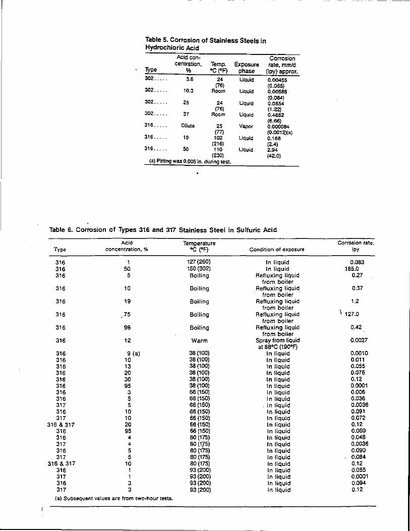
Table 5. Corrosion of Stainless Steels in Hydrochloric Acid
Acid con· Corrosion centraticn, Temp. Exposure rate, mmld
Type % •c (•FJ phase (ipy) approx. 302 ..... 3.6 24 Uquid 0.00455
302 ..... (76) (0.065)
10.3 Room Liquid 0.00588
302 ..... 25 (0.084)
24 Uquid 0.0854
302 ..... (76) (1.22)
37 Room Liquid 0.4662
316 ..... Dilute (6.66)
25 Vapor 0.000084 (77) (0.0012)(a)
316 ..... 10 102 Liquid 0.168 (216) (2.4)
316 ..... so 110 Uquid 2.94 (230)
(a) Pitting was 0.005 in. during test. (42.0)
Table 6. Corrosion of Types 316 and 317 Stainless Steel in Sulfuric Acid
Acid Temperature Corrosion rate. Type concentration, ~~ •c (•F) Condition of exposure ipy
316 1 127 (260) In liquid 0.083 316 50 150 (302) In liquid 185.0 316 5 Boiling Refluxing liquid 0.27
from boiler 316 10 Boiling . Refluxing liquid_ 0.37
from boiler 316 19 Boiling Refluxing liquid 1.2
from boiler I 121.0 316 75 Boiling Refluxing liquid
from boiler 316 96 Boiling Refluxing liquid 0.42
from· boiler 316 12 Warm Spray from liquid 0.0027
at aa•c (190•F) 316 9 (a) 38 (100) In liquid 0.0010 316 10 38 (100) In liquid 0.011 316 13 38 (100) In liquid 0.055 316 20 38 (100) In liquid 0.076 316 30 38 (100) In liquid 0.12 316 95 38 (100) In liquid 0.0001 316 3 66 (150) In liquid 0.006 316 5 66 (150) In liquid 0.036 317 5 66 (150) . In liquid 0.0036 316 10 66 (150) In liquid 0.091 317 10 66 (150) In liquid 0.072
316 & 317 20 66 (150) In liquid 0.12 316 95 66 (150) In liquid 0.060 316 4 80 (175) In liquid 0.048 317 4 80 (175) In liquid 0.0036 316 5 80 (175) In liquid 0.090 317 5 80 (175) In liquid 0.084
316 & 317 10 so (175) In liquid 0.12 316 1 93 (200) In liquid 0.055 317 1 93 (200) In liquid 0.0001 316 3 93 (200) In liquid 0.094 317 3 93 (200) In liquid 0.12
(a) Subsequent values are from two-hour tests.
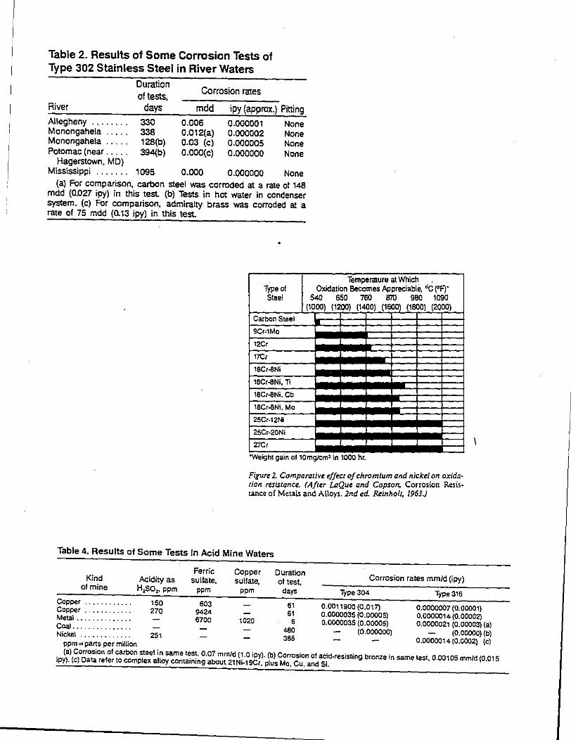
Table 2. Results of Some Corrosion Tests of Type 302 Stainless Steel in River Waters
River
Allegheny ........ . Monongahela .... . Monongahela .... . Potomac (near .... .
Hagerstown, MD}
Duration of tests,
days
330 338 128(b) 394(b}
Corrosion rates
mdd ipy (approx.) Pitting
0.006 0.012(a} 0.03 (c) O.OOO(c}
0.000001 0.000002 0.000005 0.000000
None None None None
Mississippi . . . . . . . 1095 0.000 0.000000 None (a} For comparison, carbon steel was corroded at a rate of 148
mdd (0.027 ipy) in this test (b) Tests in hot water in condenser system. (c) For comparison, admiralty brass was corroded at a rate of 75 mdd (0.13 ipy) in this test.
Type of Steel
Carbon Steel
9Cr-1Mo
12Cr
17Cr
,8Cr-8Ni
18Cr..SNi, Ti
18Cr-8Ni, Cb
18Cr-8Ni, Mo
25Cr-12Ni
25Cr-20Ni
2iCr
Temperature at Which . . . Oxidation Becomes Appreciable, 'C ('F)'
540 650 760 870 980 1090 (1000) (1200) (1400) (1600) (1800) (2000)
"WeJght gam of 10mg/Cm' 1n 1000 hr.
Figure 2. Comparative effect of chromium and nickel_ on oxi~ation resistance. (After LaQue and Copson, Corro:non Resistance of Metals and Alloys. 2nd ed. Reinholc, 1963.)
Table 4. Results of Some Tests in Acid Mine Waters
Ferric Kind Acidity as sulfate,
of mine HzSOz. ppm ppm
Copper ............ 150 603 Copper ............ 270 9424 Metal .............. 6700 Coal. .............. Nickel ............. 251
ppm= parts per million
Copper Duration sulfate, of test,
ppm days
61 61
1020 6 460 365
Corrosion rates mm/d (ipy)
Type 304
0.0011900 (0.017) 0.0000035 (0.00005) 0.0000035 (0.00005)
(0.000000)
Type 316
0.0000007 (0.00001) 0.0000014 (0. 00002) 0.0000021 (0.00003) (a)
(0.00000) (b) 0.0000014 (0.0002) (c)
{a) Corrosion of carbon steel in same test, 0.07 mm/d {1.0 ipy). (b) Corrosion of acid~resisting bronze in same test, 0.00105 mm/d (0.01 5 ipy). (c) Data refer to complex alloy containing about 21Ni·19Cr, plus Mo, Cu. and Si.
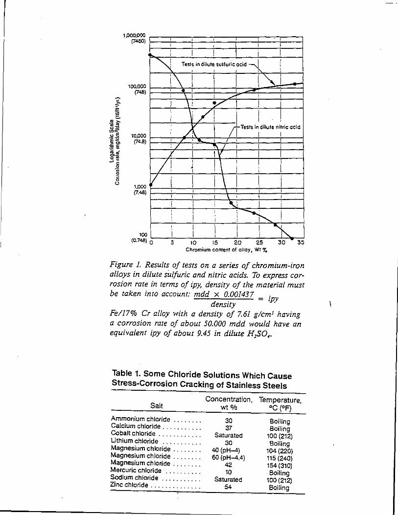
~
~ ~ .. ,..
B~ <lli'r
1,000,000 (7480)
100,000 (748)
u E 10,000 e '< (74.B) ~~ ii~ o<D -'~
0
~ 1; (.)
1,000 {7.48 )
I I I I ' I
' i i I I ! I I I I
~ ' Tests in dilute sulfuric acid """- I ' ' I I
i_\ I I I i"" I
I I -' I I I
: _il : ......r" I I
! \i v I ! i i :/1 I i ! '
. I
ftTests in1
dilute ni;ric acid I
v I I L~
I ' I I I I :/ I ~.I I I '
1 I I I I I i
/! I I ' I i I
' I I i ' v ' I I \ I I i ! I I ' I i I I I I
I I I \ ' ! I
l I i \J I ' I
' i ' ~ I \ I ' ' : ' I i i I "h. I I I I I ! i 100
(0.748) 0 5 10 15 20 25 30 35 Chromium content of aHoy, Wt "•
Figure 1. Results of tests on a series of chromium-iron alloys in dilute s'u/furic and nitric acids. To express corrosion rate in terms of ipy, density of the material must be taken into account: mdd x 0.001437
= ipy density
Fe/17% Cr alloy with a density of 7.61 glcmJ having a corrosion rate of about 50.000 mdd would have an equivalent ipy of about 9.45 in dilute H1SO,.
Table 1. Some Chloride Solutions Which Cause Stress-Corrosion Cracking of Stainless Steels
Salt
Ammonium chloride ....... . Calcium chloride .......... . Cobalt chloride ........... . Uthium chloride .......... . Magnesium chloride ....... . Magnesium chloride ....... . Magnesium chloride ....... . Mercuric chloride ......... . Sodium chloride .......... . Zinc chloride ............. .
Concentration, Temperature, wt Ofo oc (OF)
30 '31
Saturated 30
40 (pH-4) 60 (pH-4.4)
42 10
Saturated 54
Boiling Boiling
100 {212) Boiling
104 (220) 115 {240) 154 (310) Boiling
100 {212) Boiling
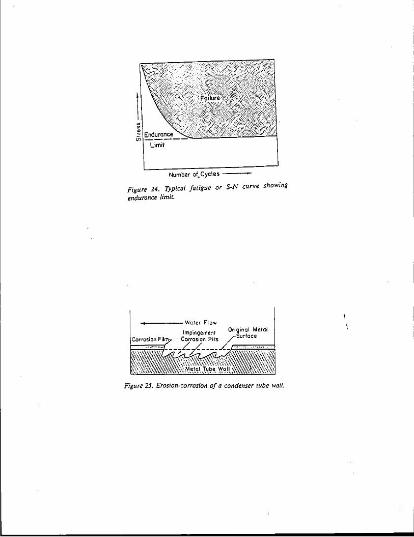
r----------------------------------------------------------
Limit
Number oi. Cycles
Figure 24. Typical fatigue or S-N curve showing
endurance limit.
~--------Water Flow
Figure 25. Erosion-corrosion of a condenser cube wall.
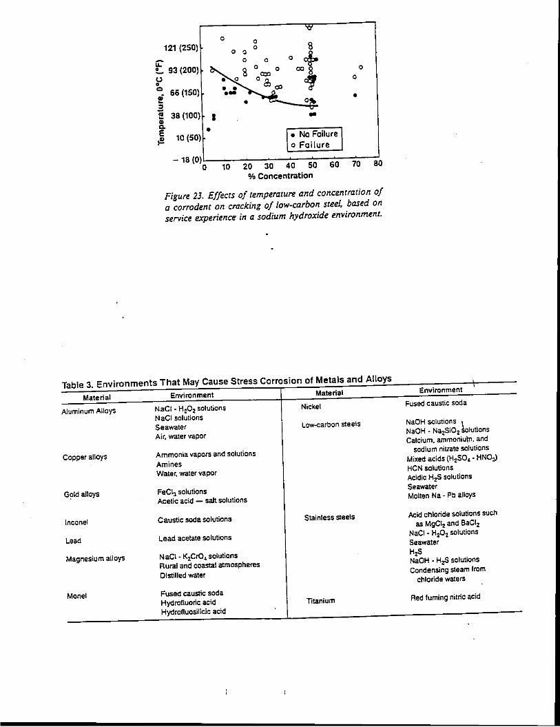
"' 0 0
121 (250) 0 8 0 0 oot u: 0 0 0
t.. 93 (200) 8 0 0 0
(.) = • • 0 oa, of 0
0 66 (150) • • "' .; ·- Olfo • - • :I ...,. iii 38 (100) I - -" c. • r. No Failure I E ,!! 10 (50)
o Failure
- 18 (0) 0 10 20 30 40 50 60 70 80
% Concentration
Figure 23. Effects of temperature and concentration of a corrodent on cracking of low-carbon steel, based on service experience in a sodium hydroxide environment.
Table 3. Environments That May Cause Stress Corrosion of Metals and Alloys
Material
Aluminum Alloys
Capper alloys
G~ld allays
lnconel
Lead
Magnesium alloys
Monel
Environment
NaCI - H20 2 solutions NaCI solutions Seawater Air, water vapor
Ammonia vapors and solutions Amines Water, water vapor
FeC\3 solutions Acetic acid - salt solutions
Caustic soda solutions
Lead acetate solutions
NaCI - K2Cr04 solutions Rural and coaStal atmospheres Distilled water
Fused caustic soda Hydrofluoric acid Hydrofluosilicic acid
Material
Nickel
Low-carbon steels
Stainless steels
Titanium
Environment
Fused caustic soda
NaOH solutions \ NaOH - Na2Si02 Solutions Calcium, ammoniu\n. and
sodium nitrate solutions Mixed acids (H2SO, • HN03) HCN solutions Acidic H2S solutions Seawater Molten Na. Pb allays
Acid chloride solutions such as MgCI2 and BaCI2
NaCI • H20 2 solutions Seawater HzS NaOH • HzS solutions Condensing steam from
chloride waters
Red fuming nitric acid
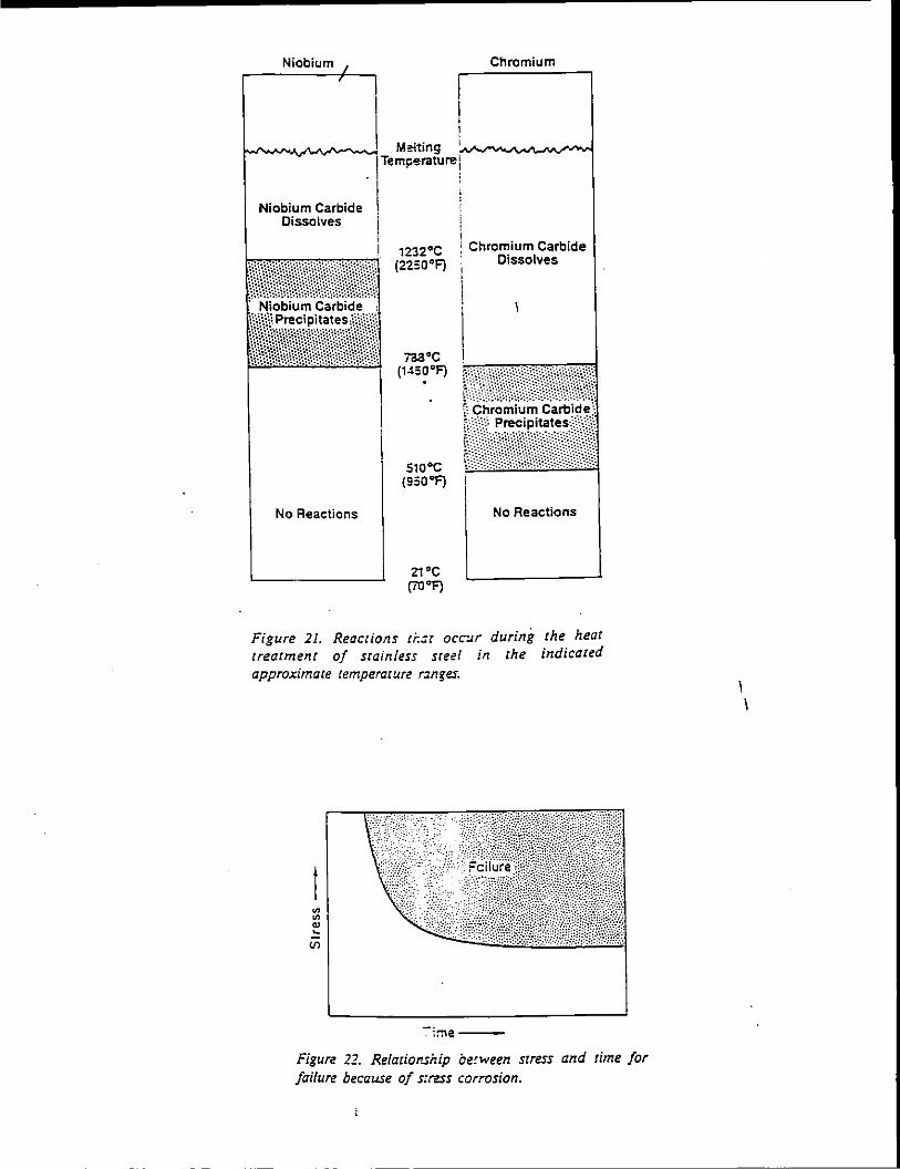
Niobium
Niobium Carbide Dissolves
Chromium
1232°C (2250°F)
Chromium Carbide Dissolves
No Reactions
703°C (14so•FJ .
s1o•c (950"F)
21°C (70"F)
Figure 21. Reactions ti:ar occ-.1.r treatment of stainless steel in approximate temperarure r3nges.
No Reactions
during the
the heat indicated
-:"be---
Figure 22. Relaciof'.sirip be!ween srress and time for failure because of s:ro.ss corrosion.
' '
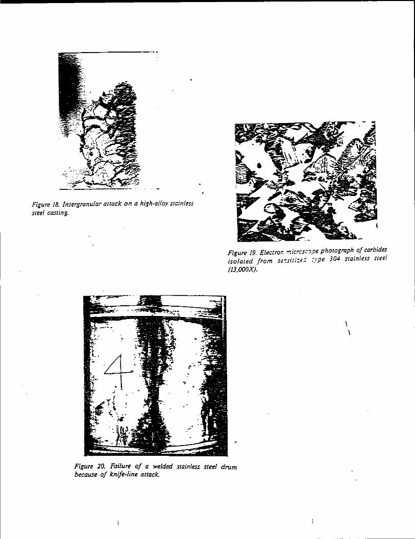
Figure 18. Intergranular attack on a high~alloy stainless steel casting.
. /j ; LL
I
' l .;
Figure 19. Electror. micrcs::op< photograph of carbides isolated from sec.siti:;.:: :ype 304 stainless steel
(JJ,OOOX).
' '
Figure 20. Failure of a welded stainless steel drum because of knife-line arrack.
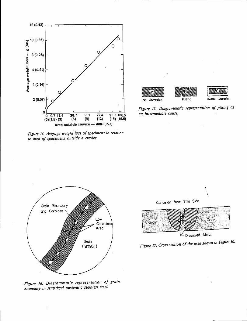
12 (0.42) ,-.-.--.....---..,...----.,..-----,
...,. 10 (0.35) ·o N
.£. 0
"' I 8 (0.28) 0
~ ~
~ -~ 6 (0.21) 0
; ~ 0 ~ 4(0.14) / ~ 0
2 (0.07) I of, ' , · ..
0 9.7 19.4 38.7 58.1 77.4 ---::;rc,o 106.5 (15) (16.5) (0)(1.5) (3) (6) (9) (12)
Area outside crevice - mm:z (in.2)
Figure 14. Av~rage weight loss of specimens in relation to area of specimens outside a crevice.
Groin Boundary
and Carbides
Groin (18%Cr)
Figure 16. Diagrammatic representation of grain boundary in sensitized austenitic stainless steel.
jj
-No Corrosion Pitting
iaca: 1.. - ~ Oieroll Corrosion
Figure 15. Diagrammatic representation of pitting as an intermediate cause.
Corrosion from This Side
Figure 17. Cross section of the area shown in Figure 16.
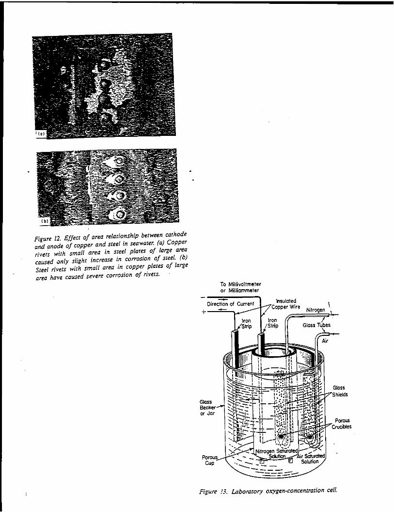
Figure 12. Effect of area relationship between cathode and anode of copper and steel in seawater. (a) Copper rivers with small area in steel plates of large area caused only slight increase in corrosion of steel. (b) Steel rivets with small area in copper plates of large area have caused severe corrosion of rivers.
To Millivoltmeter or Milliammeter
,,_ " . oratory oxygen-concentration cell. ,,·,u·e .'3. Lab
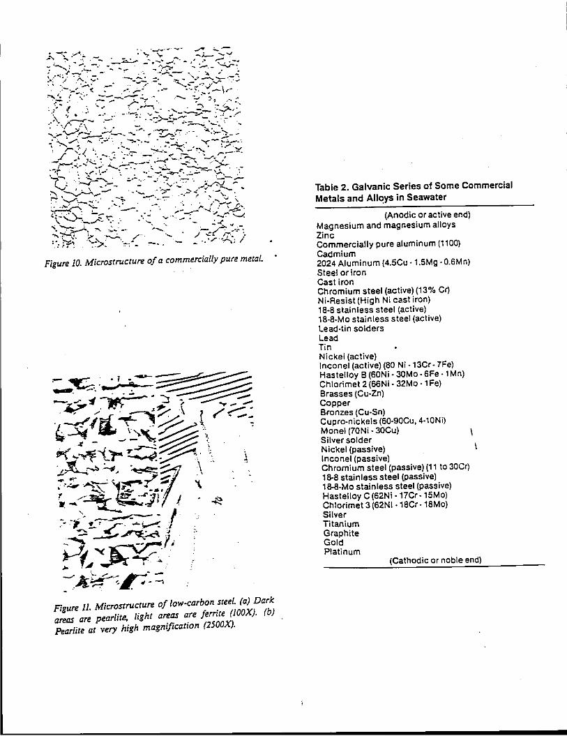
--.. -·- --· ...,.,.. -,_:._, --~ :"'4:;- _,......._ . '::- ....... -. _.....,
~ .. _ .... ·, . .:-..... :;. ' ' .
.
~ ~-- -~·- --~-;r 4;:.- .. l '( _.;..-.__ ..
~-:~~q.:-' -~--~:__ -~_:~-7·_--:·. ~/-. >~ ~ ... ,'._;.-·,: -- . ,..,--:-- -...;.., ~ \ ..............-. _r _,_ ·. ..... .. -- . ....,_ ""-"!
'\ ~-:- ,· -.~ ... :__ '-.......... - ~ ..:.-<._ -"".:...-. ~ ~.:. ~ -~ /''. ..... . ./ ~~:.....: .. ·. :_·_. ~ -~'>- ··~: ... _ -.. . . ·,.r··A; I
Figure 10. Microstructure of a commercially pure metal.
Figure 11. Microstructure of /ow-carbon ~tee!. (a) Dark areas are pearlite, light areas are ferrzte (JOOX). (b) Pearlite at very high magnification (2500X).
Table 2. Galvanic Series of Some Commercial Metals and All~ys in Seawater
(Anodic or active end) Magnesium and magnesium alloys Zinc Commercially pure aluminum (1100) Cadmium 2024 Aluminum (4.5Cu -1.5Mg- 0.6Mn) Steel or iron Cast iron Chromium steel (active) (13% Cr) Ni-Resist (High Ni c".st iron) 18-8 stainless steel (active) 18-8-Mo stainless steel (active) Lead-tin solders Lead Tin Nickel (active) lnconel (active) (80 Ni -13Cr- 7Fe) Hastelloy B (60Ni- 30Mo- SFe- 1 Mn) Chlorimet 2 (66Ni- 32Mo- 1 Fe) Brasses (Cu-Zn) Copper Bronzes (Cu-Sn) Cupro-nickels (60-90Cu, 4-10Ni) Monel (70Ni- 30Cu) Silver solder Nickel (passive) lnconel (passive) Chromium steel (passive) (1 1 to 30Cr) 18-8 stainless steel (passive) 18-8-Mo stainless steel (passive) Hastelloy C (62Ni -17Cr -15Mo) Chlorimet 3 (62Ni ·18Cr -18Mo) Silver Titanium Graphite Gold Platinum
(Cathodic or noble end)

Car: cr. Cer.:~r
Moist ;lmmcnium
Chloride
+
Pas: -;t-----l Ccrhcca I
---
----~~-
Currer.t Flew
+
: r.c :.:se ·. !;.-:.:e l
Fi•ure 9. Seccion of a dry cell or bacw·;; .. \[nO, ~ally is added as a polarizer for longer o;<W/ life.
Table 1. Electromotive Force Series, 25"C (77° F)l•l
Electrode reaction
Standard electrode potential, V \b)
(Ac:rl9 end) SodiL., Magr.:sium Beryl.·um Alurr.'cum Man~:nese Zinc Chrcr::ium Iron Cadr..:um Coba.: Nicke: Tin Lead Hydr:~;en
Cop~=' Cop1=ar Silve' P\atirum Gold
Na- Na• Mg- Mg+• Se- Be""•
+e + 2e + 2e + 3e + 2e + 2e + 3e + 3e + 2e + 2e + 2e + 2e + 2e + 2e + 2e
AI - Ar~•• Mn- Mn•• Zn-- Zn""• Cr-- cr••• Fe- Fe+++ Cd- Cd++ Co- co•• Ni- Ni++ Sn-- sn•• Pb-- Pb•+ H
2- 2H+
Cu- cu•• cu- cu· Ag- Ag• Pt- Pt•• Au- Au•••
+e +e + 2e + 3e
- 2.712 -2.34 - 1.70 - 1.67 - 1.05 - 0.762 - 0.71 - 0.44 - 0.402 - 0.277 - 0.250 - 0.136 - 0.126
0.000 + 0.345 + 0.522 + 0.800 + 1.2 + 1.42
(Nccle end) {a) !-':'dro,en is the reference point. (b) There are two schools
of thc-~gl'lt on + v'rsus - sign on these voltages; the main thing::: l<eep in mind is that !he more active {the more minus in this ta.:1e) :he more the metal tends to oxidize {lose electrons orcor:Ce).
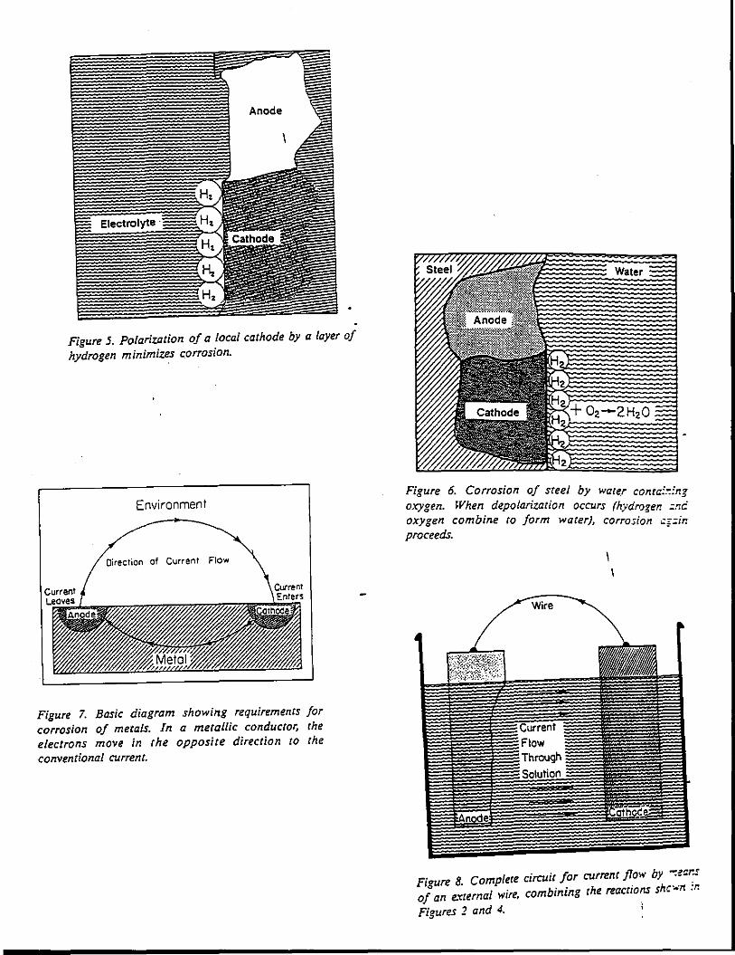
Figure 5. Polarization of a local cathode by a layer of hydrogen minimizes corrosion.
Environment
Direction of Current Flow
Figure 7. Basic diagram showing requirements for corrosion of metals. In a metallic conductor, the electrons move in the opposite direction to the conventional current.
Figure 6. Corrosion of steel by wate.r conta:.":ng oxygen. When depolarization occurs (hydrogen =mi oxygen combine ro form water), corrosion ::g=m proceeds.
Figure 8. Complete circuit for currenc flow by -:ecr.s of an e.'Cternal wire, combining the reactions shc---·n :r.
Figures 2 and 4.
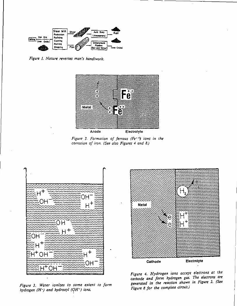
I
Figure I. Narure reverses man's handiwork.
~ +-
Anode Electrolyte
Figure 2. Formation of ferrous (Fe· -y ions in rhe corrosion of iron. (See also Figures 4 and 8.)
Cathode Electrolyte
Figure 3. Water ionizes to some extent to form hydrogen (H·j and hydroxyl (qH-; ions.
Figure 4. Hydrogen ions accept electrons at rhe cathode and form hydrogen gas. The elecrrons are generated in the reaction shown in Figure 2. (See Figure 8 for the complete circuit.)
'
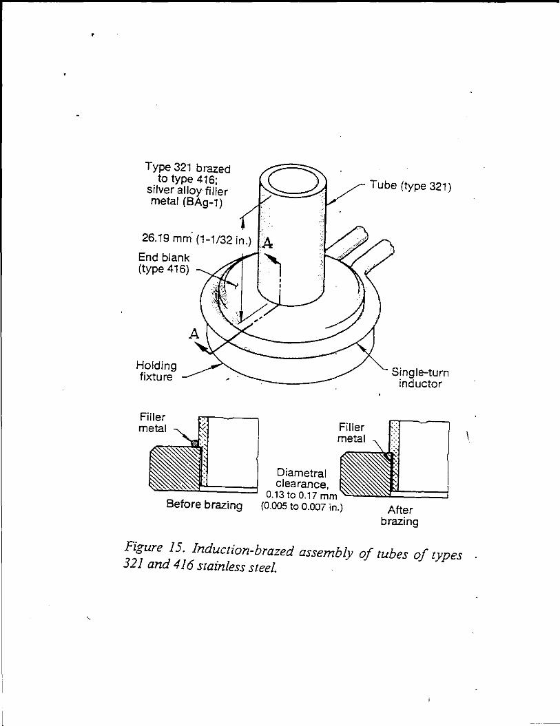
•
Type 321 brazed to type 416;
silver alloy filler metal (BAg-1)
26.19 mm (1-1/32 in.)
End blank (type 416)
Holding fixture
Filler metal
Before brazing
Filler metal
Tube (type 321)
Single-turn inductor
After brazing
Figure 15. Induction-brazed assembly of tubes of types 321 and 416 stainless steel.
I
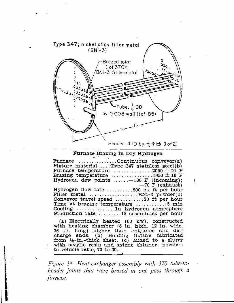
'
Type 347; nickel alloy filler metal (8Ni-3)
Brazed joint (I of 370);
BNi-3 filler metal
:l ,)~o
-1:)\l,)\)' )J,_.:
Header, 4 10 by 1 ~ thick (I of 2)
Furnace Brazing in Dry Hydrogen - - . '
Furnace ........... ; ... Continuous conveyor(a.) Fixture material .... Type 347 stainlesS steel(b) Furnace temperature ............... 2050 + 10 F Brazing temperature ........... · ..... 1950 + 10 F Hydrogen dew points ...... -100 F (incoming) ;
-70 F (exhaust) Hydrogen fiow rate .......... 600 cu ft per hour Filler metal ................... BNi-3 powder(c) Conveyor travel speed .......... _.30 ft per hour Time at brazing temperature ............ 5 min Cooling ............... In hydrogen atmosphere Production rate ......... 15 assemblies per hour
(a.) Electrically heated (60 kw), constructed with heating chamber (6 in. high, 12 in. wide, 36 in. long) higher than entrance and dis~ charge ends. (b) Holding fixture fabricated from %-in.-thick sheet. (c) Mixed to a. slurry with acrylic resin and xylene thinner; powderto-vehicle ratio, 70 to 30.
Figure 14. Heat-exchanger assembly with 370 tube-toheader joints that were brazed in one pass through a furnace.
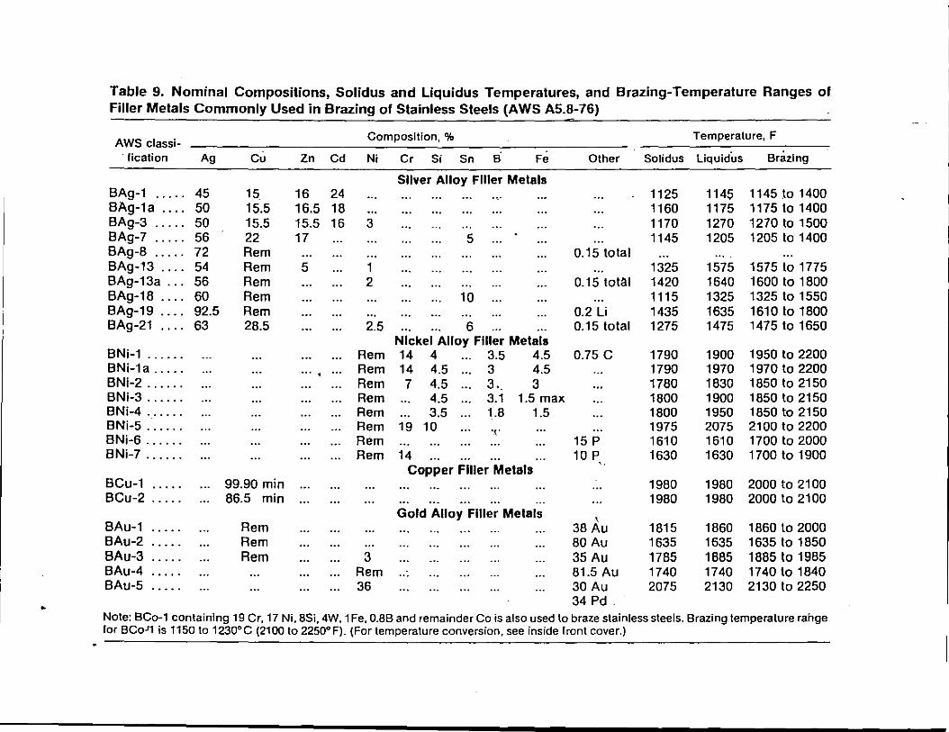
Table 9. Nominal Compositions, Solidus and Liquidus Temperatures, and Brazing-Temperature Ranges of Filler Metals Commonly Used in Brazing of Stainless Steels (AWS A5.8-76)
AWS classi- Composition, % Temperature, F
·tication Ag c.:. Zn Cd Ni Cr Si Sn B Fe Other Solidus liquidus Brazing
Sliver Alloy Filler Metals BAg-1 ..... 45 15. 16 24 1125 1145 1145 lo 1400 BAg-1a .... 50 15.5 16.5 18 1160 1175 1175 to 1400 BAg-3 ..... 50 15.5 15.5 16 3 1170 1270 1270 to 1500 BAg-7 ..... 56 22 17 5 1145 1205 1205 to 1400 BAg-8 ..... 72 Rem 0.15 total BAg-13 .... 54 Rem 5 1 1325 1575 1575 to 1775 8Ag-13a ... 56 Rem 2 0.15 total 1420 1640 1600 to 1800 BAg-18 .... 60 Rem 10 1115 1325 1325 to 1550 BAg-19 .... 92.5 Rem 0.2 Li 1435 1635 1610 to 1800 BAg-21 0 ••• 63 28.5 2.5 6 0.15 total 1275 1475 1475 to 1650
Nickel Alloy Filler Metals BNi-1 ...... Rem 14 4 3.5 4.5 0.75 c 1790 1900 1950 to 2200 8Ni-1a ..... .... Rem 14 4.5 3 4.5 1790 1970 1970 to 2200 BNi-2 ...... Rem 7 4.5 3 •. 3 1780 1830 1850 to 2150 BNi-3 ...... Rem 4.5 3.1 1.5 max 1800 1900 1850 to 2150 BNi-4 ...... Rem 3.5 1.8 1.5 1800 1950 1850 to 2150 BNi-5 ...... Rem 19 10 '.(,' 1975 2075 2100 to 2200 BNi-6 ...... Rem 15 p 1610 1610 1700 to 2000 BNi-7 ...... Rem 14 10 p 1630 1630 1700 to 1900
Copper Filler Metals ..
BCu-1 •• 0 •• 99.90 min 1980 1980 2000 to 2100 BCu-2 ..... 86.5 min 1980 1980 2000 to 2100
Gold Alloy Filler Metals ' BAu-1 Rem 38 Au 1815 1860 1860 to 2000
BAu-2 Rem 80 Au 1635 1635 1635 to 1850 BAu-3 Rem 3 35 Au 1785 1885 1885 to 1985 BAu-4 Rem ... 81.5 Au 1740 1740 1740 to 1840 BAu-5 36 30 Au 2075 2130 2130 to 2250
34 Pd. Note: BCo-1 containing 19 Cr, 17 Ni, BSi, 4W, 1 Fe, 0.88 and remainder Co is also used to braze stainless steels. Brazing temperature rahge lor BCoJ1 is 1150 to 1230°C (2100 to 2250°F). (For temperature conversion, see inside front cover.)
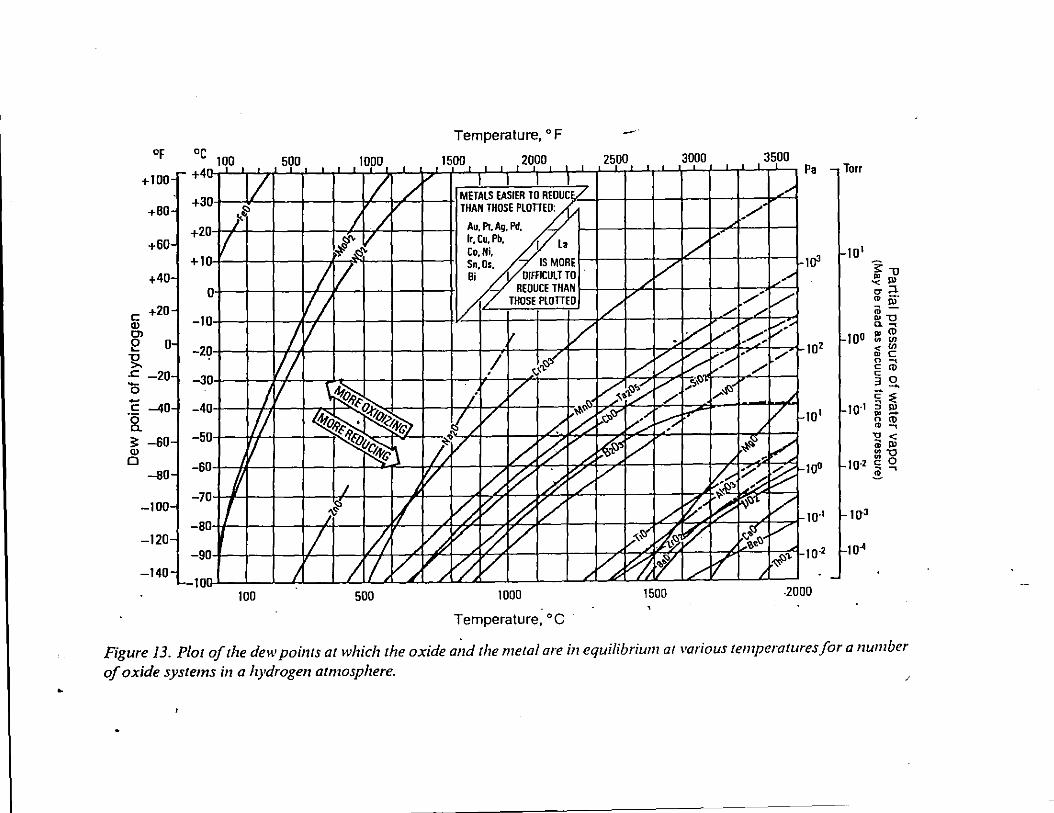
•
Of
+100
+80
+60
+40
c +20 Q) Ol e o ~ .c -20 0 c: -40 ·g_ 5: -60 Q)
0 -60
-100
-120
-140
oc TOO +4 A
+3 I ] !:>
!<.~
+2 ) /' v +I J
0
-1 J
-2 J
-3 ]
I J
l/ J 'I
-4
-5
)1 :L
-6
-7
-8
-9 )
-10' ' 100
500 . -
l VI 1/
.L
Temperature, oF
1000 1500 2000 - ~-- I . I I -~- I
/ / v I L _l I
METALS EASIER TO REOUC'/ THAN THOSE PlOTIEO:
/ ./ Au, Pl. Ag, Pd, !:>"' v lr. Cu. Pb, I lo
;f ,<:>"' Co,Ni,
I v Sn,Os. IS MORE Bi OIFACULTTO
REDUCE THAN
Ill I/ THOSE PlOTIEO
v II v I !:I< . 1-'"'
~~~ v i
~ 7L / ~~<:!
o-9., • rq<'~ /. /;: -9'-"ov~ ~1
~~v 1./: ~ v ;; /..
v l0 ~ # ~ I ~
~ ? v ~ ~ [# v I I~ v# ~ ~ v
_L[Lv~.tr _L ~ / . /
500 1000
Temperature, oc
-· 2500 --, 3000
I/ v
/
;/ v
.v / / v
...-<.~ v ~~ "" /
-;. .. ~ v; l-'l l?"
~~v v
/ ~-v"~ ~ ~
~ ~ ff' / 1500
3500 .L I
_/·
/-/ /
v·· .......... ; [,-· . ....... /
..... -$)
~~ , ./. 7 ~~ -Y: .;;
~ ~1)'1.
f.~<;, -o•
v
---
1-_./
/ ;;:"' /
./.
/ 1-
~ ~ 1-
v ~
Pa
TCJ'l
102
TO'
to"
Torr
101
~"U .e! "' ,.::l. "' --ro~
"" c.~
too e: ~ < (/) .. c 0 ~
§ ro 3 0 --c: ::;:
to·• 3 "' .. -o ro .. ~ " < <il "' :::-o
10·2 c: 0 i"""'
w·• I-To"
#"' "I o-2 f-TO ..
-2000
Figure 13. Plot of the dew points at which the oxide and the metal are in equilibrium ar various temperaruresfora number of oxide systems in a hydrogen atmosphere.
/
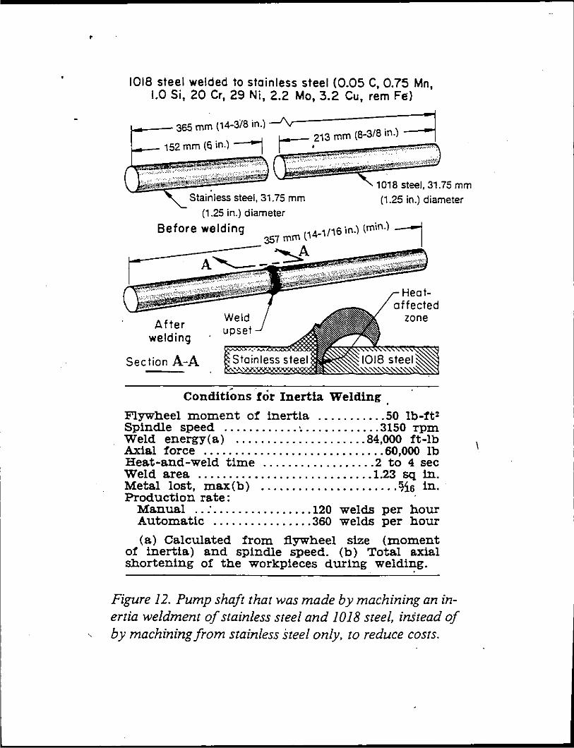
'
1018 steel welded to stainless steel (0.05 C, 0.75 Mn, 1.0 Si, 20 Cr, 29 Ni, 2.2 Mo, 3.2 Cu, rem Fe)
f--- 365 mm (14-3/8 in.) _..Py . 1 I "' ~ 213 mm (8-3/8 ln.) 1 .___ 152 mm (6 in.) ___, r---= • ~-- ----···· ·······--··· '\·
I -~·.,.·~'~ J -~- """"""" , ~"":"":'"'~"'·'·.... (~~·:- ... Cl'',"'0·""',8.,,s .. t.eel·. 3,,.1 ... 75 mm O!Zl!i::i~·:l!'li!R''i'~;.; ~·~ :' '!"~-:: .. ::~.,!~ :.:-;:··~~~ ii!!~=~~~.
Stainless steel, 31.75 mm
After welding
Section A-A
(1.25 in.) diameter
Heataffected
zone
Conditions for Inertia Welding
Flywheel moment o:r: inertia ........... 50 lb-ft2
Spindle speed ............ ~ ............ 3150 -rpm Weld energy(a) ..................... 84,000 ft-lb Axial force ............................. 60,000 lb Heat-and-weld time .................. 2 to 4 sec Weld area ............................ 1.23 sq in. Metal lost, max(b) ...................... %s in. Production rate: ·
Manual .. : . ............... 120 welds per hour Automatic ................ 360 welds per hour
(a) Calculated !rom flywheel size (moment o! inertia) and spindle speed. (b) Total axial shortening o! the workpieces during weldi~g.
Figure 12. Pump shaft that was made by machining an inertia weldment of stainless steel and 1018 steel, in.Stead of by machining from stainless steel only, to reduce costs.
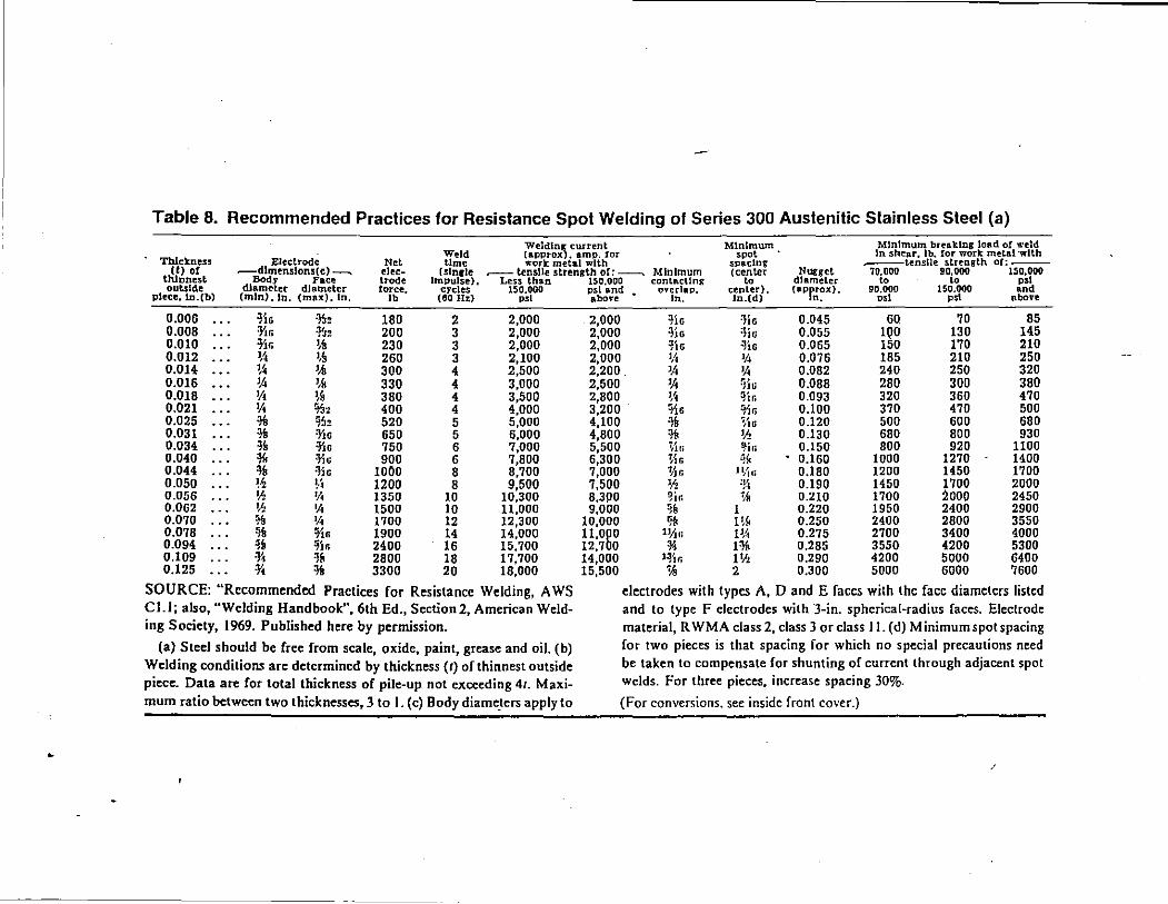
Table 8. Recommended Practices for Resistance Spot Welding of Series 300 Austenitic Stainless Steel (a)
Weldin~ current Minimum Minimum breaking load o! weld
Thickness Weld (aPPtox • amp. tor spot In shear, lb, !or work met.n.l·wlth
Elect.rode Not Ume work metal with spacing ..---tensile strength or:--(!) of .--dlmenslons(e)--.. elee- (slnrle .---tensile strenRlh or:---. Minimum (center Nugget 70.000 90,000 150,000
thinnest Body Face trade Impulse). Less than 150,000 contRctlnr to diameter to to "'' outside diameter diameter force, crcles 150.000 psi and overlap, center), capr~~x>. 90,000 150.000 and piece, ln.(b} (min). In. (max), In, Jb (60Hz) "'' above ln. ln.( d) "'' "'' above
0.006 ~JG ·13, 180 2 2,000 2,000 ~JG =J.JG 0.045 60 70 85 0.008 =Yin ~32 200 3 2,000 2,000 =}Js :HG 0.055 1QO 130 145 0,010 =}'jr, '·~ 230 3 2,000 2,000 ~16 ~lo 0.065 150 170 210 0.012 1,~ ·.~ 260 3 2,100 2,000 lA 'II 0.076 185 210 250 0.014 1,~ 'AI 300 4 2,500 2,200. 'A 'A 0.082 240 250 320 0,016 'A ·.~ 330 4 3,000 2,500 'A !Jiti 0.088 280 300 380 0.018 'A
'·" 380 4 3,500 2,800 1,1 qjr, 0.093 320 360 470
0.021 'A %:z 400 4 4,000 3,200 'i\s "' 0.100 370 470 500 d6 0.025 % ~~!! 520 5 5,000 4,100 ~B ~'lli 0.120 500 600 680 0.031 % !JiG 650 5 6,000 4,800 ~- lJ.! 0.130 680 800 930 0.034 ~· :Y,u 750 6 7,000 5,500 %.fi ~·~~ 0.150 800 920 1100 0.040 *' =JiG 900 6 7,800 6,300 %6 ~~ 0.160 1000 1270 1400 0.044
~· !lie 1000 8 8,700 7,000 %r. 1Vi·• 0.180 1200 1450 1700 0.050 ~~ ~/, 1200 8 9,500 7,500 lf.! =!~ 0.190 1450 1700 2000 0.056 'h 1fl 1350 10 10,300 8,300 ~ir. % 0.210 1700 2ooo 2450 0.062 'h '!' 1500 10 11,000 9,000 ~fl 1 0.220 1950 2400 2900 0.070 ')!, 'II 1700 12 12,300 10,000 % H~ 0.250 2400 2800 3550 0.078
~· o/J.r. 1900 14 14,000 11,0~0 ll!J.fi H~ 0.275 2700 3400 4000 0.094 ~i lj'Jr. 2400 16 15,700 12,7 0 * 1% 0.285 3550 4200 5300 0.109 :y, ~~ 2800 18 17,700 14,000 l~J:r. I'll 0.290 4200 5000 6400 0.125 .. •• 3300 20 18,000 15,500 'AI 2 0.300 5000 6000 7600
SOURCE: "Recommended Practices for Resis<ance Welding, A WS electrodes with <ypes A, D and E faces with <he face diameters listed Cl.l; also, "Welding Handbook", 6th Ed., Section2, American Weld- and to type F electrodes with 3-in. spherical-radius faces. Elec<rode ing Society, 1969. Published here by permission. material, R WMA class 2, class 3 or class II. (d) Minimum spot spacing
(a) Steel should be free from scale, oxide, paint, grease and oil. (b) for two pieces is that spacing for which no special precautions need
Welding conditions are determined by thickness (I) of thinnest outside be taken to compensate for shunting of current through adjacent spot
piece. Data are for total thickness of pile-up not exceeding 4r. Maxi- welds. For three pieces. increase spacing 30%.
mum ratio between two thicknesses, 3 to I. (c) Body diame_ters apply to (For conversions. see inside front cover.)
•
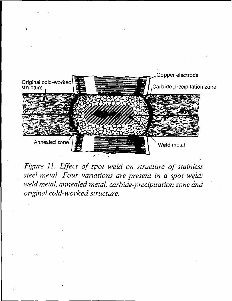
'
Copper electrode Original cold-worked structure Carbide precipitation zone
Annealed zone
.•
Figure II. Effect of spot weld on structure of stainless steel metal. ·Four variations are present in a spot w~Jd: weld metal, annetiled metal, carbide-precipitation zone and original cold-worked structure.
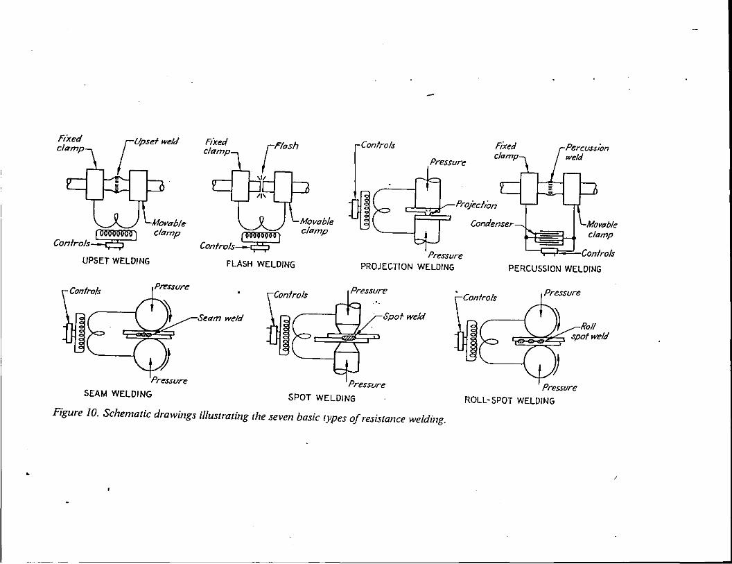
-- --·--------------------
fixed clamp
FLASH WELDING
Controls Controls
Seam weld
SEAM WELDING SPOT WELDING
fixed
Pressure
Pressure PROJECTION WELDING
Spofweld
clamp
PERCUSSION WELDING
Controls
Pressllre ROLL-SPOT WELDING
Figure 10. Schematic drawings illustrating the seven basic types of resistance welding.
• /
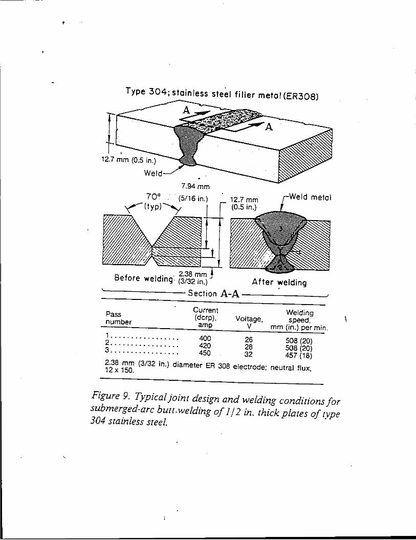
•
Type 304; stainless steel filler metal (ER308)
12.7 mm (0.5 in.}
We
7.94mm
70° · (5/16 in.} (typ}"'y
f I . . 2.38 mm
Be ore we dmg. (3/3-2 in.}
12.7 mm (0.5 in.}
After welding '---------Section A-A ----------J
Current Pass (dcrp), number amp
Welding Voltage, speed,
V mm (in.} per min. 1................. 400 2 .. " """""". 420 3 .. """" """. 450
26 508 (20} 28 508 (20} 32 457 (18}
2.38 mm (3/32 in.} diameter ER 308 electrode; neutral flux, 12 X 150.
Figure 9. Typical joint design and welding conditions for submerged-arc buu.welding of I/ 2 in. thick plates of type 304 stainless steel.
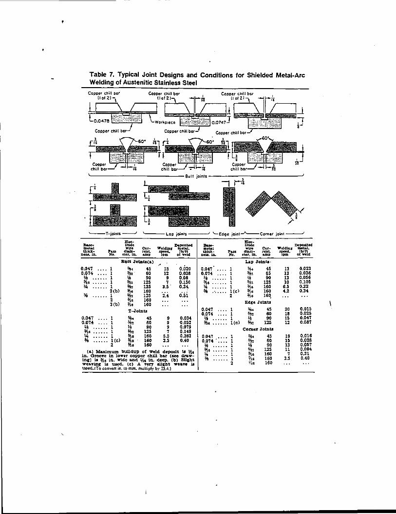
'
Table 7. Typical Joint Designs and Conditions for Shielded Metal-Arc Welding of Austenitic Stainless Steel
Copper chill bor Ool21\
I \_Workp1e.ce
U \ I ·c.a•1• \';''F?J@\
Copper c:hil I bar Copper c:,ill bor-J
'---T-joints ---.J
0.047 •.•. 0.074 .•.. ;& *• '.4
0.047 ••.. 0.074 .... ;I .Joia •••••• "" ..... . l! ..... .
-...... ""' Ou-PIUI <IIlJa.- rmt.
No. etcr, Ill. &mp
1 1 1 1 1 2(b) 1 2 3(b)
1 1 1 1 1 1 (e) 2
Butt ~Ob:l.tl(:a) -%-1 45 15 ll:. 60 12 ;1 90 9 %2 125 7 l\, 125 3.5 . iis 160 ~b 125 2.4 -ns 160 na 160 T-lolnts
45 60 90
125 160 160 160
9 9 9 7
5.5 3.5
o.02o 0.038 0.08 0.150 0.3~
0.51
0.034 0.052 0.079 0.149 0.262 0.40
{a.) Maximum bullclup of weld depcalt 1a ;\t ln. Groove 1t1. lower copper c:h.lll bar (&ee drawing) 1a ii, 111 ln. wtdo and. ;{6 ln. deep. (b) Sllght wea.v1ng La used. (c) A very allg.bt wea.ve 1a used.!To c:onven in. 10 mm. mulliply by !SA.)
'
{' '--Edge joint_...,__Corner joint---'
ElK• . ..... 'W'1re cur-
Pus dla.a:!.- rmc, No. etcr, Ill. amp
0.047 • • . . I 0.074 .•.• 1 ~-8 l ¥.r.a 1 '4 I % ..••.• l(cl
2
0.047 . • • • I 0.074 •••• I ;1 . . . . . . 1 ~s ...... l(c)
0.047 ...• 1 0.074 .•••• 1 lii 1 =Ka 1 \4 1 ;; 1
2
Lap Joints·
"" 45 ll: 65 l,8 90 %3 125 :n.a 160 ~8 160 ;l.a tsq
Edre Jol.D.t.s
~.. 45 ll: 60 ~' 90 %:: 125
Comer loi.Dt.s
"" 45 ll: 60 ;s go ~::: 125 :ria 160 ;ts 160 ;is 160
Depoatted. Wllldllla' metal. SPeed. lb/ft
1pm. of weld
13 13 13 10
6.5 4.2
20 18 15 12
19 15 13 11
7 3.5
0.023 0.036 0.056 0,105 0.22 0.34
0,015 0.025 0.047 0.087
0.016 0.028 0.057 0.094 0.21 0.40
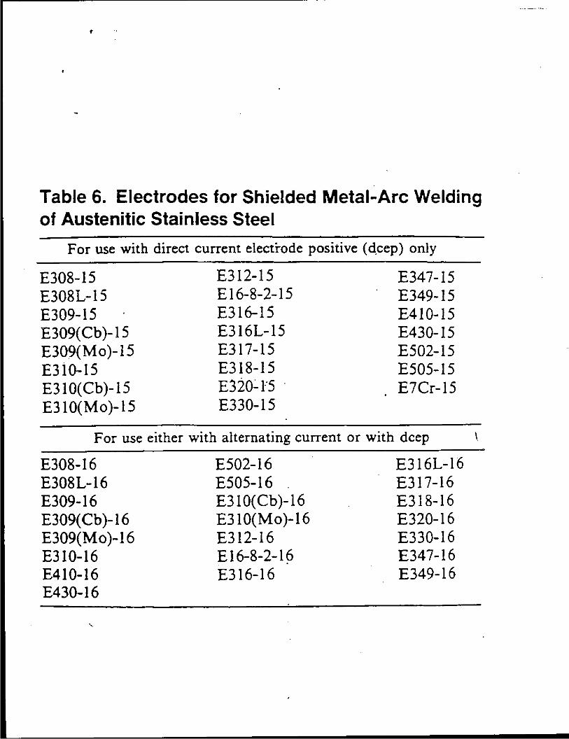
'
Table 6. Electrodes for Shielded Metal-Arc Welding of Austenitic Stainless Steel
For use with direct current electrode positive (d,cep) only
£308-15 E308L-15 £309-15 E309(Cb)-15 E309(Mo )-15 £310-15 E310(Cb)-15 E310(Mo)-15
£312-15 £16-8-2-15 £316-15 E316L-15 £317-15 £318-15 £320~1"5 . £330-15
E347-15 £349-15 E410-15 £430-15 E502-15 E505-15 E7Cr-15
For use either with alternating current or with deep I
£308-16 E308L-16 £309-16 £309( Cb )-16 E309(Mo)-16 £310-16 £410-16 £430-16
£502-16 £505-16 E310(Cb)-16 E310(Mo)-16 £312-16 £16-8-2-1~ £316-16
E316L-16 E317-16 E318-16 E320-16 E330-16 £347-16 E349-16
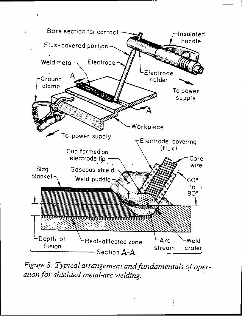
•
Flux- covered portion
Weld metal
Ground clamp
/To power supply
Cup formed on electrode tip --..
.• -
Slag blanket
Gaseous shield
Weld puddle __ _
Insulated handlE'
Electrode
holder ""
Workpiece
To power supply
Electrode covering (flux)
Core w1re
""60° to 1 80°
~7:"!1
-Depth of Heat-affected zone eld fusion stream crater
'---------Section A-A----------'
Figure 8. Typical arrangement and fundamentals of oper-ation for shielded metal-arc welding. ·
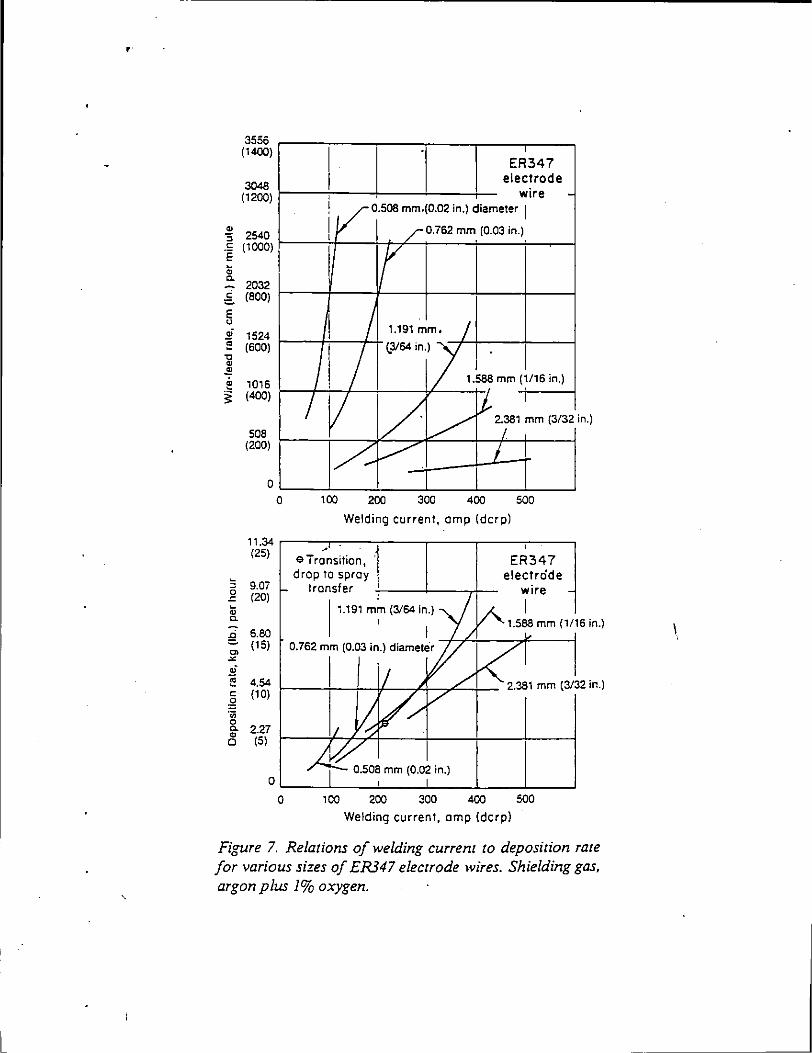
'
L
3556 (1400)
ER347
3048 (1200)
.. 2540 :;
c: (1000) .E ~ Q.
2032
electrode
' wire -
f V 0.508 mm.(0.02 in.) diameter 1
[ I ./0.762 mm (0.03 in.) .
r .g (800)
E ~
,; 1524 ~ (600)
" .. 4! ~ 1016
I I 1.191 mm. I
I l3/64 in.) l . I
I 1.588 mm (;/16 in.)
~ (400)
508 I/ / ~ IJ. 2.381 ~m (3/32 i
I n.)
(200)
~ ~ I 0
0 100 200 300 400 500
Welding current, amp (dcrp)
11.34 ,----,-.,-----.-1----,--.----.----, '25
) e Tr;ns;tion, · ER34 7 drop to spray electrode
0 9.07 transfer +,-----1----rt- wire .<:: (20) ~ 1.191 mm (3/64 in.) I c.
g 6.80 C> (15)
"' ~ t-: 4.54 g (10)
0.762 mm (0.03 in.) diameter
f-----\-~-+~-~!f---.r-f---7"'=---+-- 2.381 mm (3/32 in.)
·;;
&. " 0
2.27 (5)
0.508 mm (0.02 in.)
0~-~--~-~--~-~--~ 0 100 200 300 400 500
Welding current, amp (dcrp)
Figure 7. Relations of welding current to deposition rate for various sizes of ER347 electrode wires. Shielding gas, argon plus 1% oxygen.
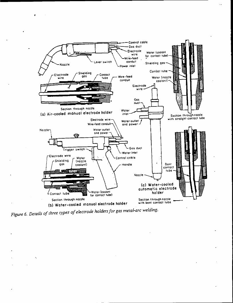
'
L'!ver switch
Section through nozzle
(a) Air-cooled manual electrode holder
Electrode wire
Section through nozzle
Power inlet
Wire-feed conduit
wire
Gas duct
Water {coolon! for contact rube)
Shielding
ContOct tube
Water inlet ~-''-'::J~==:::J Section nozzle
Water outlet and power
Gas duct
Nozzle
with straight contact tube
Bent contact
tube
(c) Water-cooled automatic electrode
holder
-(b) Water-cooled manual electrode holder Section througn nozzle with bent contact tube
Figure 6. Details of three types of electrode holders for gas metal-arc welding.
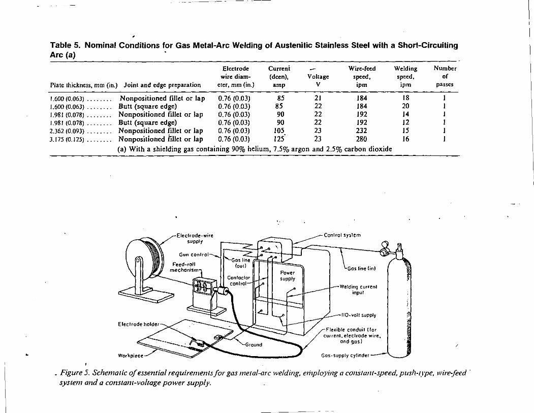
•
• Table 5. Nominal Condilions for Gas Metal-Arc Welding of Austenitic Stainless Steel with a Short-Circuiting Arc (a)
Plate thickness, mm (in.)
1.600 (0.063) ........ 1.600 (0.063) ........ 1.981 (0.078) ........ I. 981 (0.078) ........ 2.362 (0.093) ........ 3.175(0.125) ········
Electrode Curreni Wire-feed Welding wire diam- (deen), Voltage speed, speed,
Joint and edge preparation eter, mm (in.) amp v ipm ipm
Nonpositioned fillet or lap 0.76 (0.03) 85 21 184 18 Butt (square edge) 0.76 (0.03) 85 22 184 20 Nonpositioned fillet or lap 0.76 (0.03) 90 22 192 14 Butt (square edge) 0.76 (0.03) 90 22 192 12 Nonpositioned fillet or lap 0. 76 (0.03) 105 23 232 15 Nonpositioned fillet or lap 0. 76 (0.03) 125. 23 280 16
(a) With a shielding gas containing 90% helium, 7.5% argon and 2.5% carbon dioxide
Workpiece
Electrode-wire supply
Gun control
Power supply
Control system
Gas line {in)
Welding current input
110-voll supply 1:
~r. Flexible conduit (for !
current, electrode wire, oncf. g,os l
Gas-supply cylinder--'-._ _ _;
Number of
passes
/
_ Figure 5. Schematic of essemial requirements for gas metal-arc welding, e1i1ploying a cons tam-speed, pusll-rype, ll'ire:feed · system and a consram-voltage power supply.
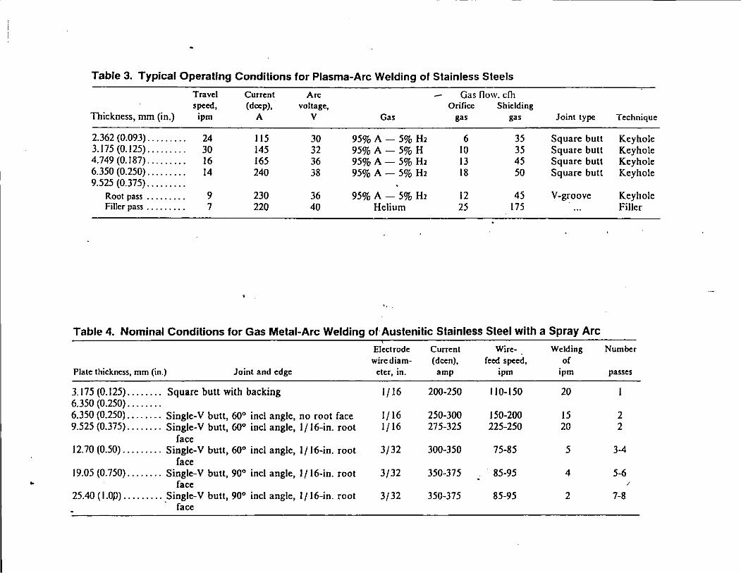
Table 3. Typical Operating Conditions for Plasma-Arc Welding of Stainless Steels
Travel Current Arc Gas flow. dh speed, (deep), voltage, Orifice Shielding
Thickness, mm (in.) ipm A v Gas gas gas Joint type Technique
2.362 (0.093) ......... 24 115 30 95% A- 5% H2 6 35 Square butt Keyhole 3.175 (0.125) ......... 30 145 32 95% A- 5% H 10 35 Square bull Keyhole 4. 749 (0.187) ......... 16 165 36 95% A- 5% H2 13 45 Square bull Keyhole 6.350 (0.250) ......... 14 240 38 95% A- 5% H2 18 50 Square bull Keyhole 9.525 (0.375) .........
Root pass ......... 9 230 36 95% A- 5% H2 12 45 V-groove Keyhole Filler pass ......... 7 220 40 Helium 25 175 Filler
Table 4. Nominal Conditions for Gas Metal-Arc Welding of Austenitic Stainless Steel with a Spray Arc
Electrode Current Wire· Welding Number wirediam· (dcen), feed speed, of
Plate thickness, mm (in.) Joint and edge eter, in. amp ipm ipm passes
3.175 (0.125) ........ Square butt with backing lf16 200-250 110-150 20 6.350 (0.250) ........ 6.350 (0.250) ........ Single-Y butt, 60° inc! angle, no root face 1/16 250-300 150-200 15 2 9.525 (0.375). . . . . . . . Single-Y butt, 60° incl angle, 1/16-in. root 1/16 275-325 225-250 20 2
face 12.70 (0.50) ......... Single-Y butt, 60° incl angle, 1/lti-in. root 3/32 300-350 75-85 5 3-4
face 19.05 (0.750) ........ Single-Y butt, 90° incl angle, 1/16-in. root 3/32 350-375 85-95 4 5-6
• face /
25.40 (I.Op) ......... Single-Y butt, 90° incl angle, 1/16-in. root 3/32 350-375 85-95 2 7-8 face
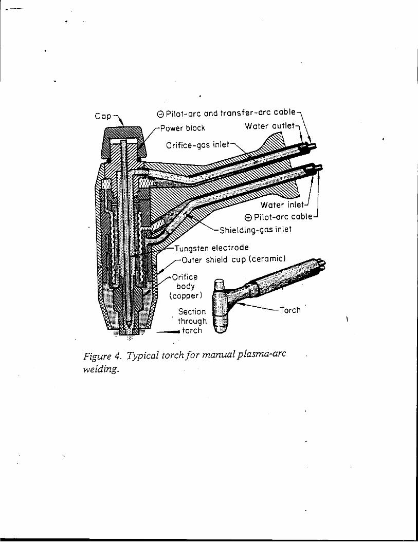
•
8 Pilot-arc and transfer-arc cable
r-1-'nw,•r block Water outlet
Orifice-gas inlet
E) Pilot-arc cable
Shielding-gas inlet
ungsten electrode Outer shield cup (ceramic)
Orific~a body
(copper l
Section through
--torch
Torch
Figure 4. Typical torch for manual plasma-arc welding.
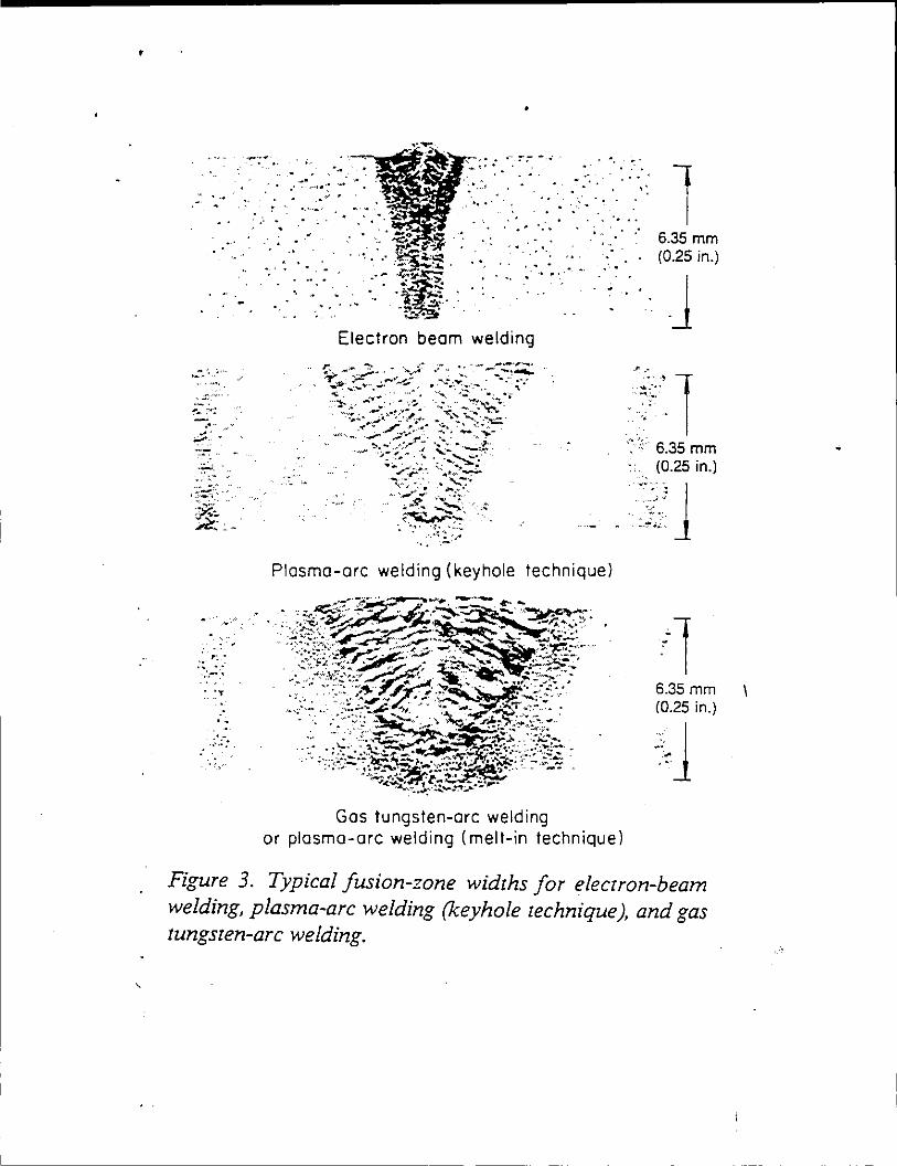
'
•.
.:.:- .. ~·,..
-~.·
.•.
. "' .. · .:.-·. : _'T
: ..
. ,·
·-. · . '"~" ...
. .... . . . ~
. -, ' . . .. .·- ......
~ . . . "
Electron beam welding
•. . : . .. ' ,.
. · ..
l 6.35 mm (0.25 in.) . .. J . - . . . .
.1< ••
......... ··1 . ·
. ...... _ ..
6.35 mm (0.25 in.)
..... ..• : .•.
... ·.. . I ·. ::.: 1
Plasma-arc welding (keyhole technique)
Gas tungsten-arc welding
6.35 mm (0.25 in.) ... ·1 .,
·-. •.
or plasma-arc welding (melt-in technique)
Figure 3. Typical fusion-zone widths for electron-beam welding, plasma-arc welding (keyhole technique), and gas tungsten-arc welding.
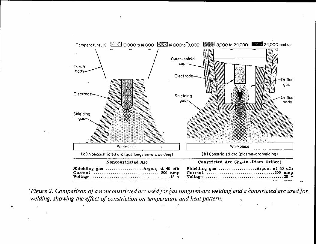
•
Temperature, K: C2:IJ 10,000 to 14,000 B§:~<J 14,000 tOIB,OOO IBJ 18,000 lo 24,000 .. 24,000 and up
Shielding
Outer- shield cup
Shielding
(a) Nonconstricted ore (gas tungsten-ore welding)
Nonconstrlcted Arc
'Jf:Ew--Orifice gas
(b) Conslricled ore (plasma-ore welding)
Constricted Arc (?16-In.-Diam Orifice)
Shielding g68 .................. Argon, at 40 cfh Shielding gas .................. Argon, at 40 cfh Current ................................ 200 amp current ................................ 200 amp Voltage ..................................... 15 v Voltage ..................................... 30 v
'Figure 2. Comparison of a nonconstricted arc used for gas tungsten-arc welding· and a constricted arc used for. welding, showing the effect of constriction on temperature and heat pattern .
/
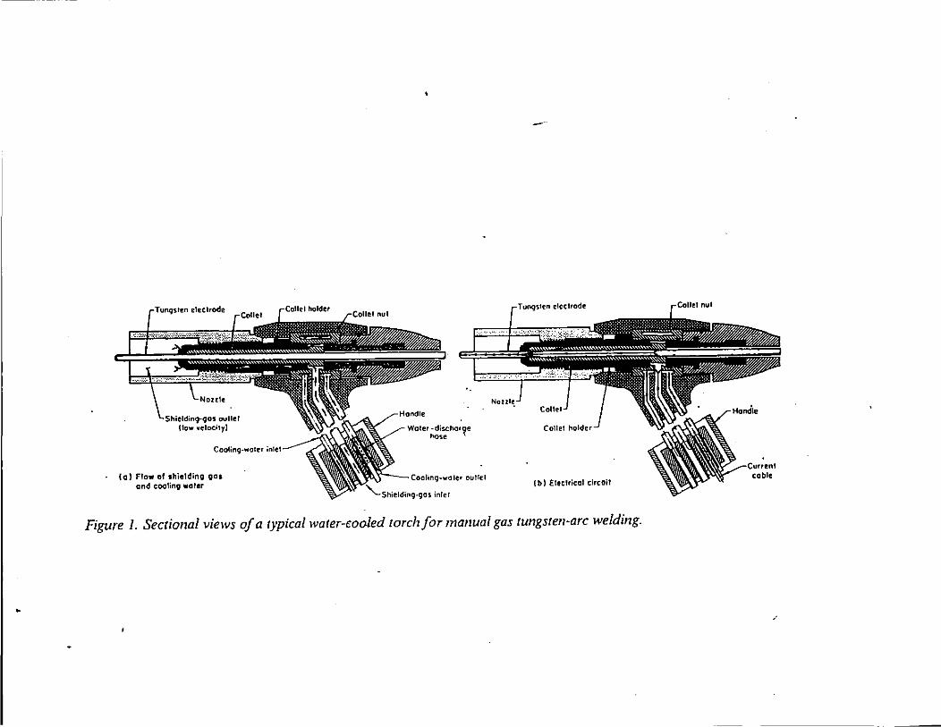
•
Coolinq-waler inlel
(a) Flow of shielding oas gnd cooling water
'·
- T'"""""" electrode
I b) Eleclric:al circOil
Figure 1. Sectional views of a typical water-waled torch for manual gas tungsten-arc welding .
cable
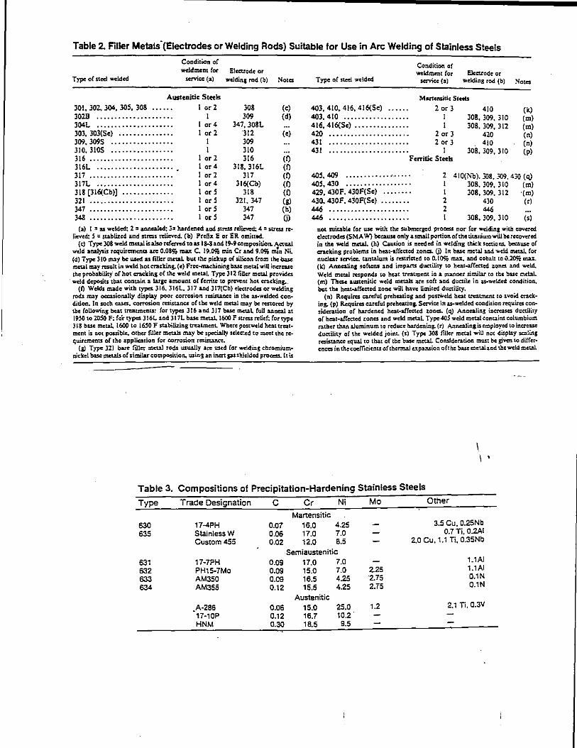
Table 2. Filler Metals-(Eiectrodes or Welding Rods) Suitable for Use in Arc Welding of Stainless Steels
Type of stcd welded
Conditicn of wddmcnt for
servic: (a)
Austenitic Steels
301, 30Z. 304, 305, 308 I or 2 302B ..................... I 304L ····················· 1 or4 303, 303(5e) ............... 1 or 2 309. 3095 ................. I 310. 3105 ················· I 316 ······················· I or 2 316L ..................... . I or4 317 ······················· I or 2 317L ····················· I or 4 318 [316(Cb)] .............. I or S 321 ······················· I or S 347 ······················· I or 5 348 ······················· I orS
Electrode or welding rod (b)
308 309
347, 308L 312 309 310 316
318, 316L 317
316(Cb) 318
321. 347 347 347
Notes
(c) (d)
(e)
(f) (f) (f) (f) (f) (g) (h)
Gl (a) I =as welded; 2 =annealed; 3= hardened and. st~ relieved; 4 =stress re-o
lieved:. S = stablized and stress rclicvcd. (b) Prefix E or ER omiucd. {c) Type 308 weld meW is also rdctRd to as la.8 aod 19-9 campositioa. Actual
wdd analysis requirements arc 0.089& max C. 19.09& min Cr and 9.(1% m!n Ni.. (d) Type: 310 may be used as filler metaL but the piekup o( silicon from the base metal may result in wdd hot cracking. (e) Frcc-ma.c!Uning base metal wiU increase the probability" o( hot cracking of the weld metaL Type 312 filler metal provides weld deposits that coatain a large amount o{ ferrite to prevent hot cracking..
(l) Wc.lds made with types 316. 316L. 317 aad-317(Cb) electrodes or welding rods may OCCLSionaUy display poor corrosiort rcsistallcc in the as-wdded condition. In such cases, corrosion ~istance of the weld metal may be restored by tbe following heat tn:atments: for types 316 and 317 buc metaL fuU uncal at 1950 to 20!iO F; fo'r types 316L and 317L base metaL 1600 F stress relief: for type 3 IS base metal, 1600 to 1650 F stabilizing treatment.. Where post weld hett treatment is aot possible, other filler metals may be spccia!ly sel~cd to meet the requirements of the application {or eorrosion rcsi.sunce.
(g) Type 321 bare filler metal rods usually arc used for welding chromiumnickel base metals of similar composition. using an inert gas shielded process. lt is
Type of ncel welded
403, 410, 416, 416(5e) .•.... 403, 410 ..•..•••.......... 416, 416(5e) •.•.••••.......
420 •••·•··•••·•·••••··•·· 431 ..................... . 431 •.. ··••·•·· .......... .
Condition of wekimcnt for
service (a) Electrode or
welding rod (b)
Manensitie Sceels
2 or 3 410 I I
2 or 3 2 or 3
I
308, 309, 310 308, 309, 312
420 410
308,309,310 F eJTitic Steels
(k) (m) (m) (n) (n) (p)
405, 409 ............ •'- .. .. 405, 430 ................. . 429, 430F. 430F(5e) .•...••. 430, 430F. 430F(5e) ....•..•
446 ·••·•·••·····••····•·· 446 ..................... .
2 410(Nb). 308.309.430 (q) I 308, 309, 310 (m) 1 308,309, 312 ·(m) 2 430 (r) 2 446 1 308, 309, 310 (s)
not suitable for usC with the submerged process nor for welding with covC'cd. electrodes (SMA 'W') because only a small portion of the titanium will be r«:ovcrcd ia the weld metal. (h) Caution is needed in welding thick sections. because of cracking problems in heat-affected zones. (j) In base metal and weld metaL for nuclear service. tantalum is resuictcd to 0.10% max, and cobalt to 0.20% max. (k) Anacaling softens and impans ductility to hcat·affectcd zones and weld. Weld metal responds to heat trc:1tment in a manner similar to the base mdal. (m) These ausr.cnitic weld metals ate soft and ductile in as-weld¢4 condition. but the belt-affected. zone will have limited ductility.
(n) Requires careful prehcatiag and postWc.ld heat ucatmc:nt to avoid eraeking. (p) Requires arc!ul preheating. Service in as-welded coadition requires consideration of hardened heat-affected zones. (q) Annealing U.crc:ascs ductility of heat-affected zones and weld metal. Type40S weld metal contains columbium rather than aluminum to red LICe hardeaing. (r) Annealing is employed to increuc ductility of the welded joint. (s) Type 308 filler metal will not display scaling resistance equal to that of the base metal. Consideratioa must be given to differences in thecoc:fficienu of thermal expansion oft he base metal. a ad the weld metal
\ \
Table 3. Compositions of Precipitation-Hardening Stainless Steels
Type
630 635
631 632 633 634
Trade Designation C Cr Ni Mo Other
Martensitic 17-4PH 0.07 16.0 4.25 3.5 Cu. 0.25Nb StainlessW 0.06 17.0 7.0 0.7 Ti, 0.2A1 Custom 455 0.02 12.0 8.5 2.0 Cu. 1.1 Ti, 0.35Nb
Semiaustenitic 17-7PH 0.09 17.0 7.0 1.1Al
PH15-7Mo 0.09 15.0 7.0 2.25 1.1A1
AM350 0.09 16.5 4.25 2.75 0.1N
AM355 0.12 15.5 4.25 2.75 0.1N
Austenitic .A-256 0.06 15.0 25.0 1.2 2.1 Ti. 0.3V 17-10P 0.12 16.7 10.2. HNM 0.30 18.5 9.5
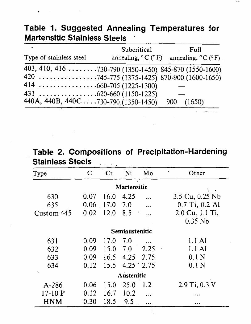
'
Table 1. Suggested Annealing Temperatures for Martensitic Stainless Steels ·
Subcritical Full Type of stainless steel annealing, ° C (° F) annealing, ° C (° F)
403, 410, 416 ........ 730-790 (1350-1450) 845-870 (1550-I600) 420 ................ 745-775 (1375-I425) 870-900 (1600-1650) 414 ............... -660-705 (1225-1300) 43I ................ 620-660 (II50-I225) 440A, 440B, 440C ... -730-790.(1350-I450) 900 (1650)
Table 2. Compositions of Precipitation-Hardening Stainless Steels . Type c Cr Ni Mo Other
Martensitic I •
630 0.07 I6.0 4.25 3.5 Cu, 0.25 Nb 635 0.06 I 7.0 7.0 0.7 Ti, 0.2 AI
Custom 445 0.02 I 2.0 8.5 2.0 Cu, I. I Ti, 0.35 Nb
Semiaustenitic
631 0.09 I 7.0 7.0 1.1 AI 632 0.09 15.0 7.0 2.25 1.1 Al 633 0.09 I6.5 4.25 2.75 0.1 N 634 0.12 15.5 4.25. 2.75 0.1 N
Austenitic
A-286 0.06 15.0 25.0 1.2 2.9 Ti, 0.3 V 17-10 p 0. I2 16.7 10.2 HNM 0.30 18.5 9.5
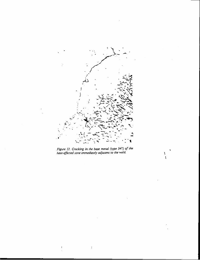
·-. ~ · .. : ,.
·. ..
i I
/
------
Figure 12. Cracking in the base metal (type 34i) of the heat-affected zone immediately adjacent to the weld. I
I
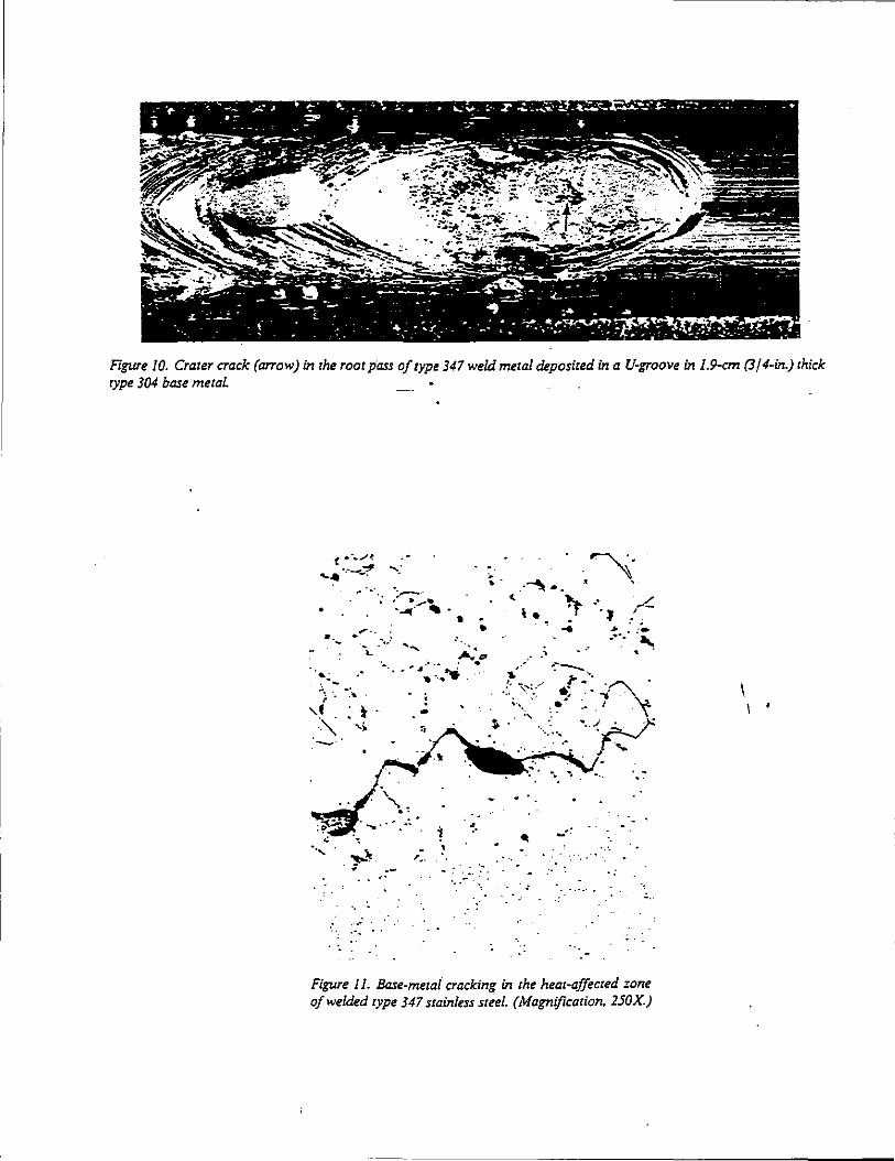
Figure /0. Crater crack (arrow) in the root pass of type 347 weld metal deposited in a U-groove in /.9-cm (3 / 4-in.) thick type 304 base metaL
•
··-
· .....
·. -··-
• . ...
• ... -·.:~
·~ .• ··- . . ·.--..... .. .• ....
-,.
~-
- .. · ..
~-. '
... ·'
Figure II. Base-meta{ cracking in the heat-affected zone of welded type 347 stainless steel. (Magnification. 2.50X.)
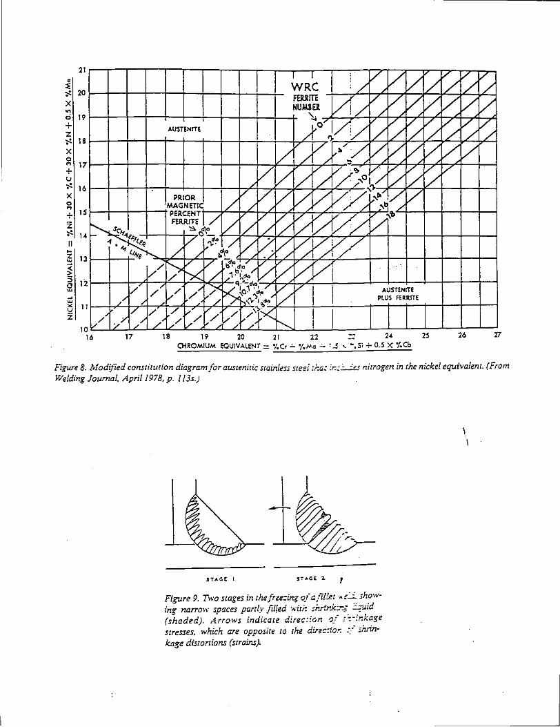
19 20 21 22 2< 25 26 'I7 CHROMIUM EQUIVALENT- •,'.Cr..:.. •f.Mc...:... :..! -.._ ... Si + 0.5 X j'.Cb
Figure 8. lvfodified constitution diagram for austenitic stainless steel :r..a: :r.:~ nitrogen in the nickel equivalent. (From Welding Journal, April 1978, p. I /3s.)
S":'.,.CE 2. ,
Figure 9. Two stages in thefree=ing of a.fil!e! ..,.!:..;:_showing narrow spaces parrly filled .... ·iti: sr.r.r.ko-... ., ':'-'id (shaded). Arrows indicate direc:ian ,_,-- c':-:r.kage stresses, which are opposite co the dfrec:ior: -~--- shrinkage disrorrions (strains).
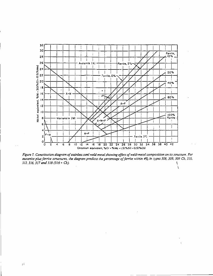
:~~~=~1 ~~=:=~~=! =~~=! ==:=:1 :=:i =~==! =~=:::1 ===! =1: I f I I • j1 I I j I Y' Fe.,ire, 28r-~-t~r-+-~-+~~~~~-+--~+-~~--~~~/·~--~~· IO%_
26 I I ! I I I ! I I I i ' X v I /! I r-.,.
1 11
I Auslenite (A) --'--1 -'---i--\1
Ferr
1
ite,51"to---yy' y I 1 I
~ 24 1 " ' I I 1 : i .If'- ' I
!! "'-1 ! i i ! I I I I i Y Y I /V [ I _,.1 2o,•t.
~:: !"l I i I I =·i"'•·,o%,W Y 1 A' I lA ! I ~ ,8~1 I I'!--.. I i i I ' VYI/1 i Y1 l/i•o;----., 1"-J -I •• 1M "'-i ! . i VV!/ :_.rl". lA I i I i 161---+---"1-<:-+ ., ! I"{ 1 I N : x~~Vl/1 l./1 J/1 i 1.---i 80% ~ 14r-i--t-,~+-~-+~~+--'-~~~~~71-'-~4-~~~~~r-~
~~ 2 ~1-+1~1~~-~~~~ ~~~'{~!/~/~V~I ~··F~/r~: ~~~~~~ ~~-+~~~ -~ lOr--I-' --;-I -+! --+-i -+~~~ -+i ----!7'1 )S(~. *-V_.,..! /~4.Y--+--7I.c:._7+-+! ---:---+1---:---! -'1---1 ~ 8 ~O<J~nsill (Mil N }'/ y x~v~.J---~1..:/:::.j./__J!i,_,l_-+---::;;. ....... l---i;:::l :....;: ~~.~.;; z li' ! I : I I I }"<C ·.·~~ / f>V I I J..---r' I I !
6
\I I i :, ',X I \ ~ "'-.-Y: I I 1 I I 4
F•',; I i I / ! M~F ! ):,--'- ! i ! I I i I I ~ K' I I y : I _..l..--i' I I ' I I ~"""; (FJI I I I
0 2 4 6 8 10 12 14 16 18 20 22 24 26 28 30 32 34 36 38 40 42 Chromium equivolent, '"IoCr • '"loMo • 1.5{%5i) •0.5(%Cb)
Fi~e 7. Conszituzion dil:zgram of stainless steel weld metal showing effect of weld-metal composition on its structure. For austenite plus ferrite structures, the dil:zgram predicts the percentage of ferrite within 4% in t)pes 308, 309, 309 Cb, 3/0, 311. 316, 317 and 318 (316 + Cb). I
I
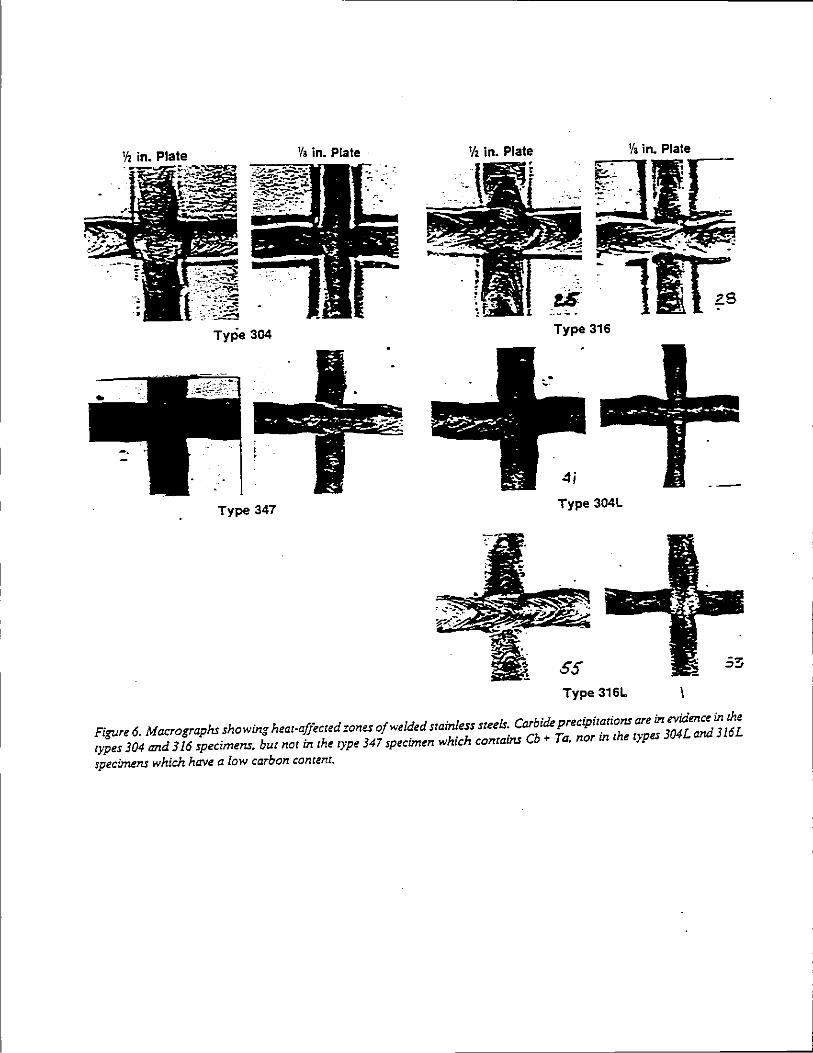
'lz in. Plate 1/a in. Plate 'h in. Plate
.. !S.
Type 304 Type 316
Type 347 Type 304L
Type 316L
Figure 6. Macrographs showing heat-affected zones of welded stainless steels. Carbide precipitations are in evidence in the types 304 and 316 specimens. but not in the type 347 specimen which contains Cb ~ Ta, nor in the types 304L and 316L
specimens which have a low carbon content.
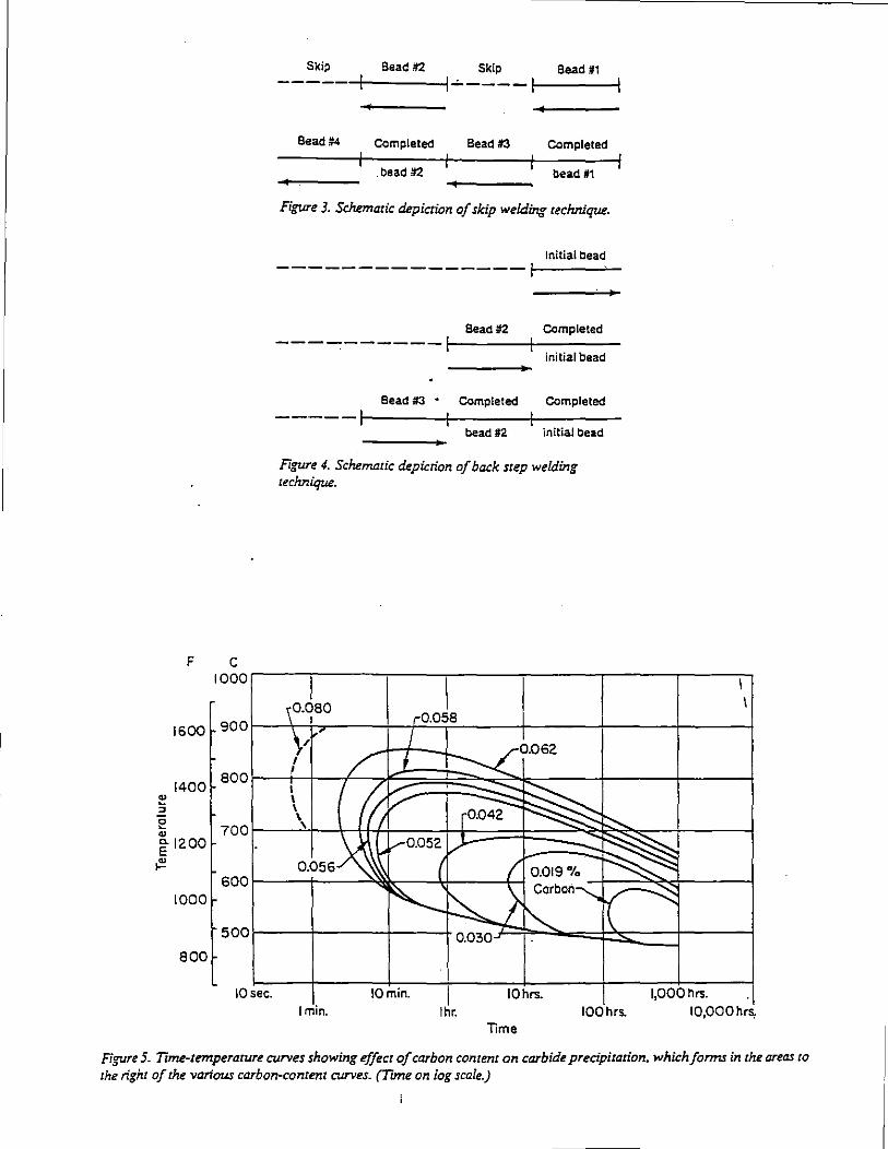
F c 1000
1600 900
1400 800
"' 5 e 700 " ~ 1200
~ 600
1000
500
800
lOsee.
Skip Bead !12 Skip Bead ~1 ----r----;
Bead #4 Completed Bead#3 COmpleled
. bead !12 bead #1
Figure 3. Schematic depiction of skip welding technique.
Initial bead ---------------~-----~-
Bead 112 COmpleted ----------1----!----
initial bead
Bead #3 • COmpleled COmpleted
----- t-------1-----t----bead #2 initial bead
Figure 4. Schematic depiction of back step welding technique.
r0.05B
0.062 I !
I I \ \
' 0.056
I min. I
I hr. IOmin. IOhrs.
Time 100 hrs.
\ \
J,OOOhrs. ·I IO,OOOhrs,
Figure 5. Time-temperature curves showing effect of carbon content on carbide precipitation. which forms in the areas to the right of the various carbon-content curves. (T~me on iog scale.)
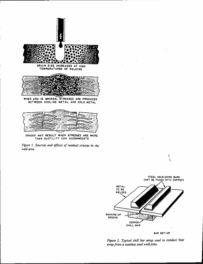
GRAIN SIZE INCREASES AT HIGH TEMPERATURES OF WE~OING
WHEN ARC IS BROKEN, BETWEEN COO~ING META~
CRACKS MAY RESU~T WHEN STRESSES ARE MORE THAN DUCTILITY CAN ACCOMMODATE
FiiJUl'e I. Sources and effects of residual stresses in the weld area.
METAL TO BE
CHILL BAR
STEEL HOLO·OOWN BARS (MAY BE WITH COPPER)
BAR SET-UP .
Figure 2. Typical chill bar serup used to conduct heat away from a stainless steel weld joint.
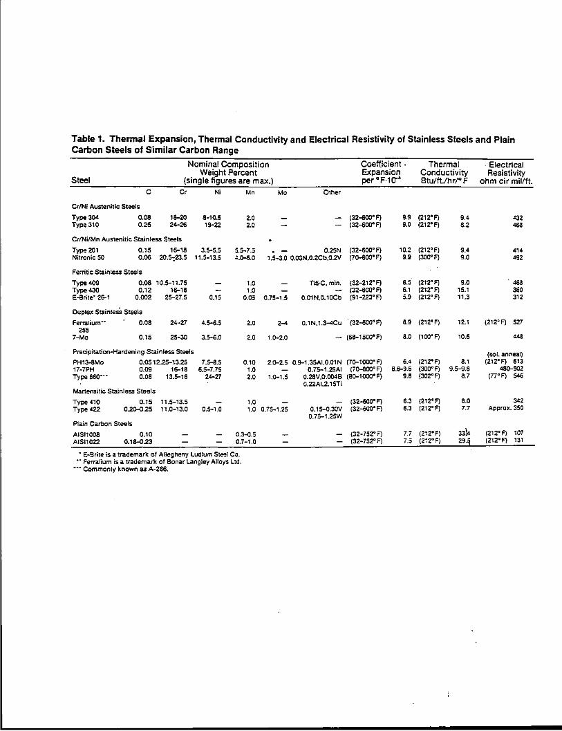
Table 1. Thermal Expansion, Thermal Conductivity and Electrical Resistivity of Stainless Steels and Plain Carbon Steels of Similar Carbon Range
Nominal Composition Coefficient . Thermal . Electrical Weight Percent Expansion Conductivity Resistivity
Steel (single figures are max.) per"F·1tr Btu/11./hr/" F ohm cir mil/ft. c Cr N; Mn Mo Other
Cr/Ni Austenitic: Steels
Tyoe304 0.08 18-20 8·10.5 2.0 (32-600" F) 9.9 (212"F) 9.4 .!32 Type 310 0.25 24-26 19-22 2.0 (32-600" F) 9.0 (212"F) 8.2 468
Cr/Ni/Mn Austenitic Stainless Steels
Type 201 0.15 16-18 3.5-5.5 5.5-7.5 0.2SN (32-600"F) 10.2 {212°F) 9.4 414 Nitronic 50 0.06 20.5:23.5 11.5-13.5 4.o-6.0 1.5-3.0 0.03N,0.2Cb.0.2V (70-600"F) 9.9 (300"F) 9.0 492
Ferritic Stainless Steels
Type 409 0.08 10.5-11.75 1.0 TiS·C, min. (32-212" F) 6.5 (212"F) 9.0 . 468 Type430 0.12 16-18 1.0 (32-600° F) 6.1 (212"F) 15.1 360 E-Brite' 26-1 0.002 25-27.5 0.15 0.05 O.iS-1.5 0.01 N,0.10Cb (91-223"F) 5.9 (212" F) 11.3 312
Duplex StainlesS Steels
Ferralium·· 0.08 24-27 4.5-6.5 2.0 2-4 0.1 N,1.3-4Cu . (32-600" F) 8.9 (212"F) 12.1 (212"F) 527 255
7-Mo 0.15 25-30 3.5-Ei.O 2.0 l.Q-2.0 (68-1 sao• F) 8.0 (100"F) 10.6 448
Precipitation-Hardening Stainless Steels (sol. anneal) PH13-8Mo 0.0512.25-13.25 7.5-8.5 0.10 2.o-2.5 0.9-1 .35A1,0.01N (7D-1 coo· F) 6.4 (212"FJ 8.1 (212°F} 613 17-7PH o.os 15-18 6.5-7.75 1.0 0.75-1.2SAI (i0-800"'F) 6.5-9.6 (300"F) 9.5-9.8 48G-502 Type s6o··· 0.08 13.5-16 24-27 2.0 1.G-1.5 0.28V,0.004B (8Q-1000"F) 9.8 (302" F) 8.7 (77"F) 546
0.22AI.2.15Ti Martensitic Stainless Steels
Type 410 0.15 , 1.5-13.5 1.0 (32--600° F) 6.3 (212"'F) 8.0 3<2 Type 422 0.20-0.25 , , .0-13.0 0.5-1.0 1.0 0.75-1.25 0.15-0.30V (32-600" F) 6.3 (212"F) 7.7 A~~rox. 350
0.75-1.2SW Plain Carbon Steels
AISI1008 0.10 0.3~.5 (32-752""1 7.i (212"F) 3314 (212"F) 107 AISI1022 0.18-0.23 0.7-1.0 (32-752"'F) 7.5 (2i2"'F) 29.3 (212°F) 131
• E-Srite is a trademark ot Allegheny Ludlum Steel Co. •• Ferralium is a trademark of Bonar Langley Alloys Ltd.
-··Commonly known as A-286.
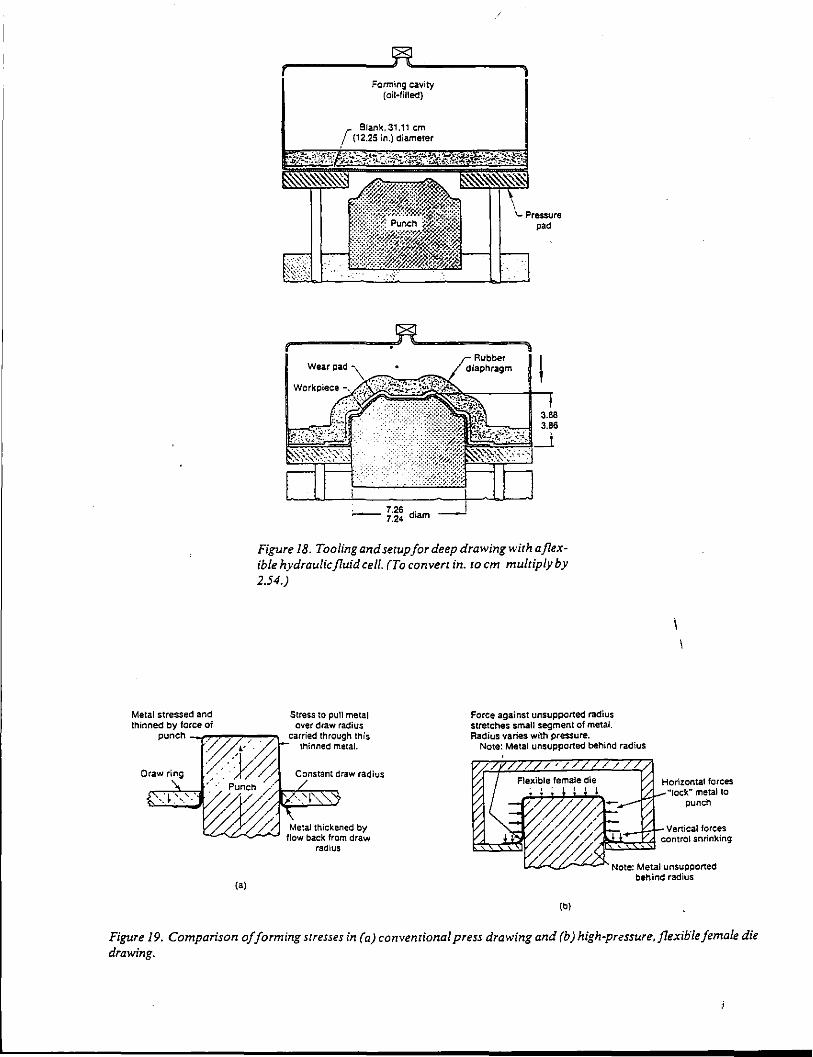
Metal stressed and thinned by force of
Wear pad
Forming cavity (oil·filled)
: 7.26 d' -7.24 lam
Rubber diaphragm
Figure 18. Tooling and setup for deep drawing with a flexible hydraulic fluid cell. (To convert in. to em multiply by 2.54.)
punch -.,r-r~,...,~~':n
Stress to pun metal over draw radius
carried through this thinned metal.
Force against unsupported radius srretches small segment of metal. Radius varies with pressure.
Note: Metal unsupported behind radius
(a)
Metal thickened by flow back from draw
radius
Horizontal forces "lock" metal to
punch
L..<..?-Z,y-'-""--" Note: Metal unsupported behind radius
(b)
Figure 19. Comparison of forming stresses in (a) conventional press drawing and (b) high-pressure,flexiolefemale die drawing.
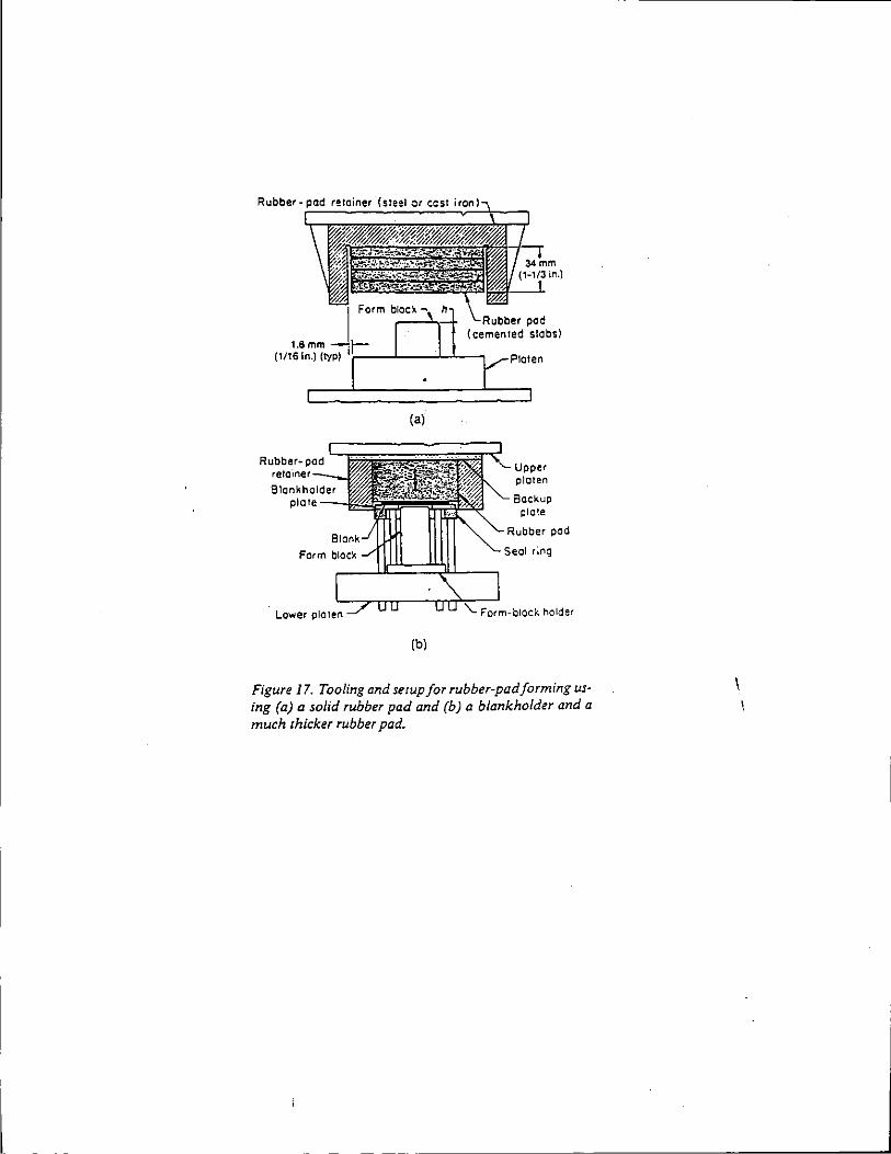
(a)
Upper platen
Backup plate
~ h<uo;o., pod
Seal r;ng
~l.JC::=:~------,
(b)
Figure 17. Tooling and serup for rubber-pad forming using (a) a solid rubber pad and (b) a blankholder and a much thicker rubber pad.
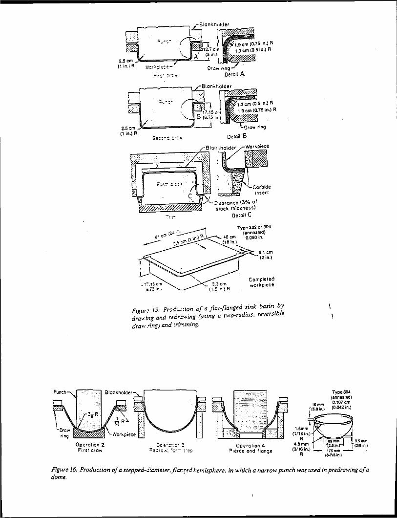
Operation 2 First draw
in.} R
Detail E
insert
:teorcnce (3% of stack thickness)
Detail C
Completed workp1ece
F<> 15. Pr~d:...::ion of o jla:-flanged sink basin_ by Iaure . . . . adius reversible
d . _ana re_.. .. -....,.1ng (usmCT a rwo-r · ra\,.m; ... - ~
drah· .ring) and tr:""'!ming.
Operation 4 P1erce and flange
4.8mm (3116in.)
A
Type304 (annealed) O.l07cm (0.042 in.)
Figure 16. Production of a scepped-i:ameter,_ficr.;<d hemisph~re. in which a narrow punch was used in predrawing of a dome.
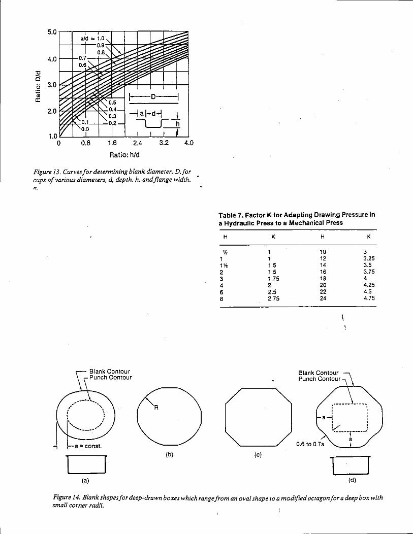
1.0 L...L__L_JL..L--L~-t__..L--1!..._.1 0 0.8 1.6 2.4 3.2 4.0
Ratio: h/d
Figure 13. Curves for determining blank diameter, D.for cups of various diameters, d, depth, h, and flange width, n.
A
(b)
(a)
Table 7. Factor K for Adapting Drawing Pressure in a Hydraulic Press to a Mechanical Press
H K H K
'h 1 10 3 1 1 12 3.25 1'h 1.5 14 3.5 2 1.5 16 3.75 3 1.75 18 4 4 2 20 4.25 6 2.5 22 4.5 8 2.75 24 4.75
\.
(----- ----.. , ' ' ' ' a-' ' ' ' ' ' v ' I '"-••·•,-•••_;
a 0.6 to 0.7a
(c)
l r (d)
Figure 14. Blank shapes for deep-drawn boxes which range from an oval shape to a modified octagon for a deep box with small corner radii.
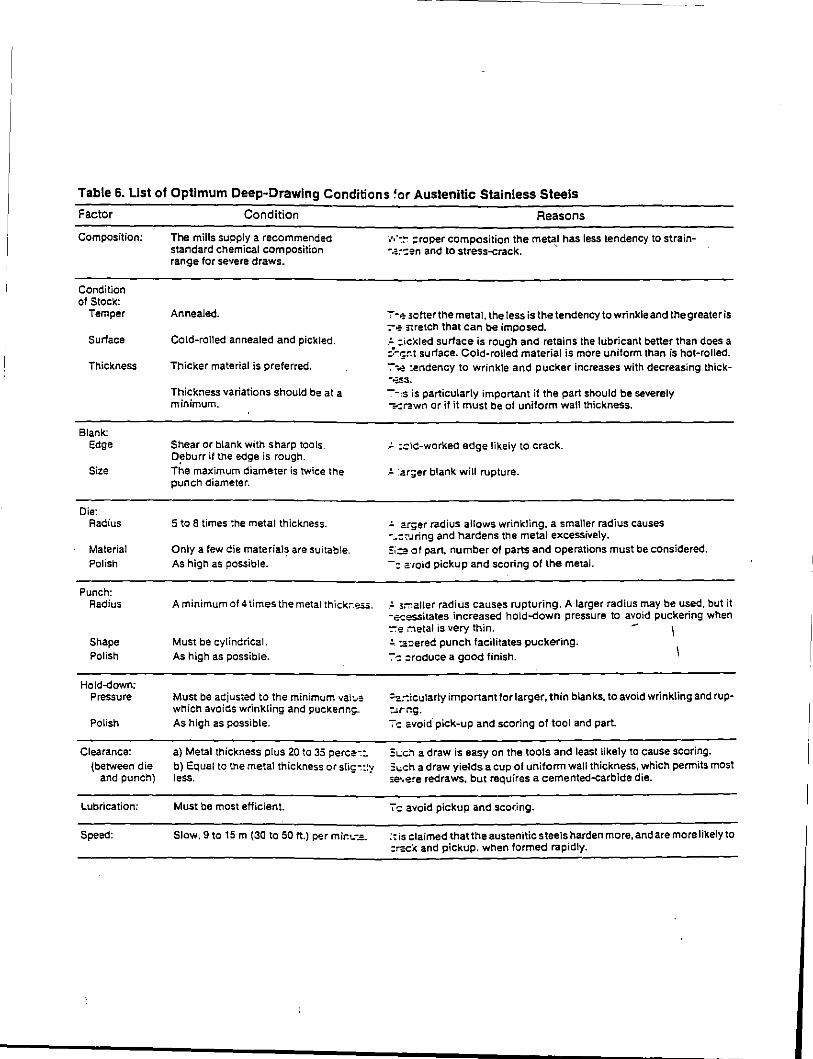
Table 6. List of Optimum Deep-Drawing Conditions ~or Austenitic Stainless Steels
Factor
Composition:
Condition of Stock:
Temper
Surface
Thickness
Blank: Edge
Size
Die: Radius
Material Polish
Punch: Radius
Shape Polish
Hold-down; Pressure
Polish
Clearance: (between die
and punch}
Lubrication:
Speed:
Condition
The mills supply a recommended standard chemical composition range for severe draws.
Annealed.
Cold-rolled annealed and pickled.
Thicker material is preferred.
Thickness variations should be at a minimum.
Shear or blank with sharp tools. Oeburr if the edge is rough.
The maximum diameter is twice the punch diameter.
5 to 8 times the metal thickness.
Only a few die material~ are suitable. As high as possible.
A minimum of 4 times the metal thick:-.~.
Must be cylindrical. As high as possible.
Must be adjusted to the minimum vai!.l! which avoids wrinkling and puckerin!;As high as possible.
a) Metal thickness plus 20 to 35 perce--:: b) Equal to the metal thickness or slic-::~v less. - ·
Must be most efficient.
Slow. 9 to 15m (30 to 50 ft.) per mir.._-.=.
Reasons
·,·,·-:~ ;:roper composition the metal has less tendency to strain--.::':en and to stress-crack. '
7-f.!' setter the metal, the tess is the tendency to wrinkle and thegreateris :-.:- s-;retch that can be imposed. .:.. :ickled surface is rough and retains the lubricant better than does a :~--:t;nt surface. Coldarolled material is more uniform than is hot-rolled. ~-..a- :endency to wrinkle and pucker increases with decreasing thick--.;s,s.
--~sis particularly important if the part should be severely -=-:l;!:wn or if it must be of uniform wall thickness.
_:.. :.::lC-worked edge likely to crack.
.:.. :ar;er blank will rupture.
:.. .arger radius allows wrinkling. a smaller radius causes --:':'.lring and hardens the metal excessively. =:;.::g of part. number of parts and operations must be considered. -= 2:1oid pickup and scoring of the metaL
_:.. s;:-:aner radius causes rupturing. A larger radius may be used, but it -ecessitates increased hold--down pressure to avoid puckering when :-:e r:1etal is very thin. - \ :.._ :a:ered punch facilitates puckering.
7-: ;:reduce a good finish.
=a:-:icularly important for larger, thin blanks, to avoid wrinkling and rup::Jrr.g. 7-:: avoid. pick-up and scoring of tool and part.
3~..:c.~ a draw is easy on the tools and least likely to cause scoring. =:~,;ch a draw yields a cup of uniform wall thickness, which permits most Y!'.e~e redraws. but requires a cemented--carbide die.
7c avoid pickup and scor.ing.
:-:is claimed that the austenitic steels harden more, and are more likely to :~cl< and pickup. when formed rapidly.
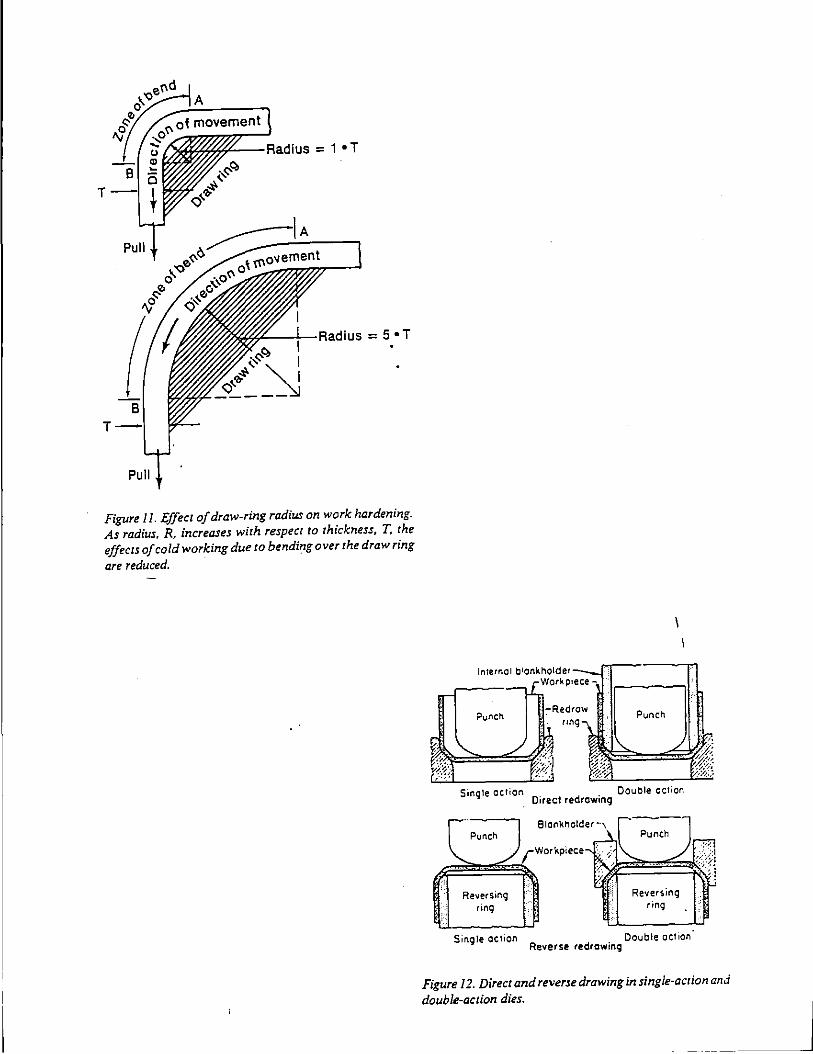
A
= 1 •T
T
= 5 •T
-~(?, I .. ~ <::>'-"'~ "' i -----~
T
Pull
Figure II. Effect of draw-ring radius on work hardening. As radius. R. increases with respect to thickness, T. the effects of cold working due to bending over the draw ring
are reduced.
,:;.
Reversing ring
Single action
Blal"'kt'lolder --,
Workpiece
Reversing ring
Double aCtion Reverse redrawing
Figure 12. Direct and reverse drawing in single~action and
double-action dies.
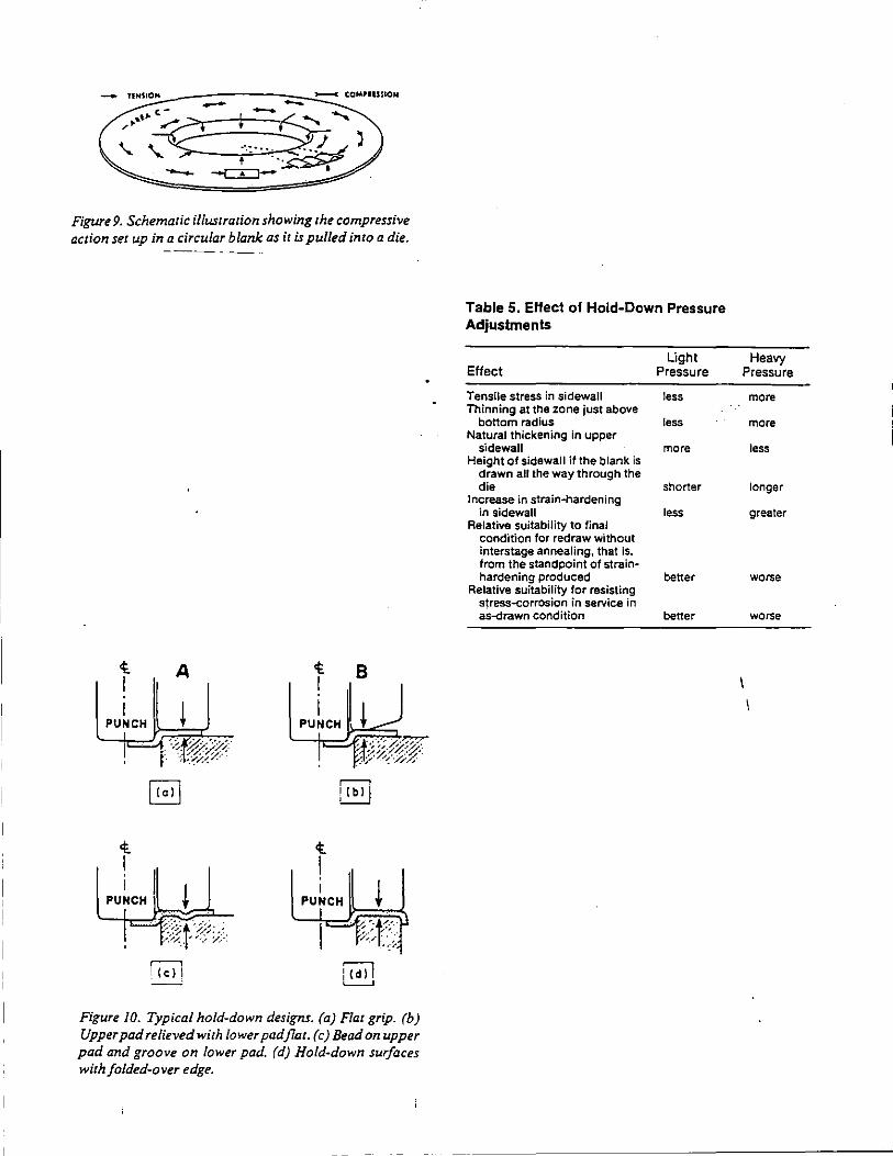
Figure 9. Schematic illustration showing the compressive action set up in a circular blank as it is pulled into a die.
t I I
PUNCH
t I
PUNCH
A
I
t I I
PUNCH
t I I
PUNCH
8
I ~
Figure 10. Typical hold-down designs. (a) Flat grip. (b) Upper pad relieved with lower pad flat. (c) Bead on upper pad and groove on lower pad. (d) Hold-down surfaces with folded-over edge.
Table 5. EHect of Hold-Down Pressure Adjustments
Effect
Tensile stress in sidewall Thinning at the zone just above
bottom radius Natural thickening in upper
sidewall Height of sidewall if the blank is
drawn all the way through the die
Increase in strain~hardening in sidewall
Relative suitability to final condition for redraw without interstage annealing, that is, from the standpoint of strainhardening produced
Relative suitability for resisting stress-corrosion in service in as~rawn condition
Light Pressure
less
less
more
shorter
less
better
better
Heavy Pressure
more
more
less
longer
greater
worse
worse
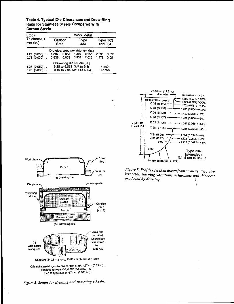
Table 4. Typical Die Clearances and Draw-Ring Radii for Stainless Steels Compared With Carbon Steels
Stock Thickness, t mm (in.)
Work Metal
Carbon Steel
Ty~e 430
Types 302 and 304
Die clearance per side. em !in.) 1.27 (0.050) .. . 1.397 0.055 1.397 0.055 0.76 (0.030) ... 0.8:!8 0.033 0.838 C.033
2.286 0.090 1.372 0.054
1.27 (0.050) .. . 0.76 (0.030) .. .
Draw-ring radius. em (in.) 6.35 to 9.525 (1/4 to 3,3; 0.19to7.94 (3/16to5i16)
Punch
(a) Drawing die
4t min 4tmin
/- 1/ork.pi&"'..e
~~~~
(c) Completed wor11:piece
{b) Trimming die
Car.:lide lr:s.ert
(1 0~ 2)
Area ~at wrinkled
'Nhen :~ieee was drawn
frcli.
:YP< ~
61.59cm (24.25 in.) long. 45.09 em (17-3/4 i:~.) wide
Original material: galvanized carbon steel. 1.27 ~"7: (0.05 i:-:.): changed to type 430, 0.787 mm {0.031 1:-.. ::
tnen to type 302. 0.787 mm 1_0.031 in.;
Fiplre 8. Setups for drawing and trimming a basin.
31.75 em (12.5 in.)
:;:j_l~==-d~i~am::e~te:r~l::::;1._ Thickness. ~r, (:r. ..
f Rockwell hardness: 1.956 (O.Oi7j (·3.5:.:-1. I c 38 (B 110) -- 1.879 (0.07-!-} {-~,
1.702 (0.06Tj (-1~. I c 39 (B 1!0) - 1.623 (0.06<) (·!2:'-.1
I I t.' 'l9 (0.009) ( .,.,
1.422 (0.1)50) (-z:<a,
31.11 em I 1.397 (0.055) ~-J.5~ (12.25 i
1
n.) 1.384 (0.05451 !4~.
I ,
i I ! ~
l.i --
1.384 (O.Q51..5, 1-i~ 1 1.333 (0.0525'1 ~~
·/---1.232 (0.04&:) 1.-~E~.
Type 304 (annealed)
. 0.145 em (0.057 ir.. 1.194 mm (0.047 in.) (-18li.O)
Figure 7. Profile of ashe// drawn from an austenitic s:w~ less sreel. showing variations in hardness and ihic.;:r..eJ: produced by drawing. 1
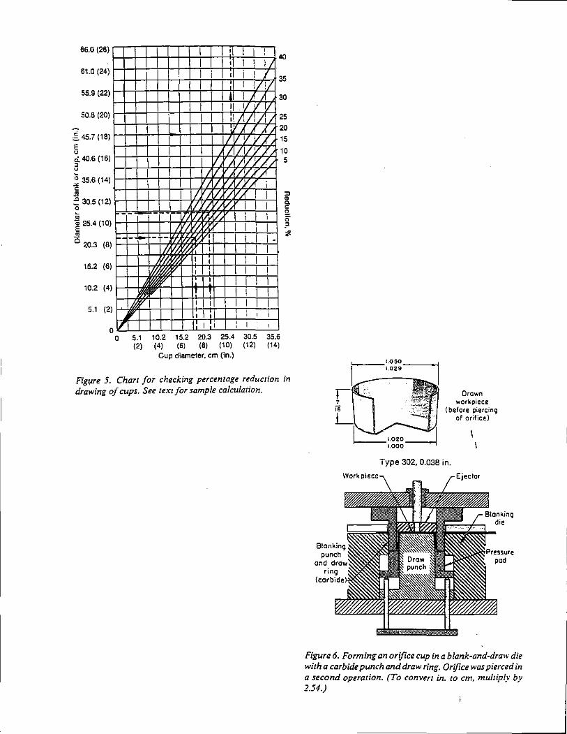
66.0 (26) I 40
! I 61.o 1241 H,-\--t-t++++-t-t-tH--o---.!,l-1·
r+-r,_~r+-rt-ri;rl i-~1/r.!/~~ 55.9 1221 Hrl-t-t+++-t-t-Hih--1'--T'-i 30
I I 1/ I 1/ 50.8 1201 f---I-I-HH-t-t-+--+1--+-ti-1+ 1, 171
1F-;71
1Y1 25
20 ,§, 45.7 1181 Hh--++1 _,...+I +1 ++-Hf-A-h-.1 .¥1 15
5 10 ·;I v.~ Q. 4().6 (16) 5 v I V. v , u
~ ~.6 (14) I-I-Hrl-t-t-t-t.fT7'hA'm7''-:---1 c I
I IV '/ v '/
1/ /. ~ I ~ 30.5 1121 f-I-HH-l-t-4t,4,H74<7'i>"+-+-!
1---1 1/. /.'/
'/. '//. i ' ~ = ~ 25.4 1101 HHrl-t-t--t.H:nf5~,LJ-+++-i--i
5 20.3 (8) ~r-i-~t:t;~rJ~~tttt=t1 I /j I
'I. I
15.2 (6) H-1--+-lt
10.2 (4 I '
I I ' I '
5.1 (2
0 lrl I 1: I I I ' 0 5.1 10.2 15.2 20.3 25.4 30.5 35.6
(2) (4) (6) (8) (10) (12) (14) Cup diameter, em (in.)
Figwe 5. Chart for checking percentage reduction in drawing of cups. See text for sample calculation.
Work ·
Drawn workpiece
(before piercing of orifice)
Type 302, 0.038 in.
Figure 6. Forming an orifice cup in a blank-and-draw die with a carbide punch and draw ring. Orifice was pierced in a second operation. (To convert in. to em, multiply by 1.54.)
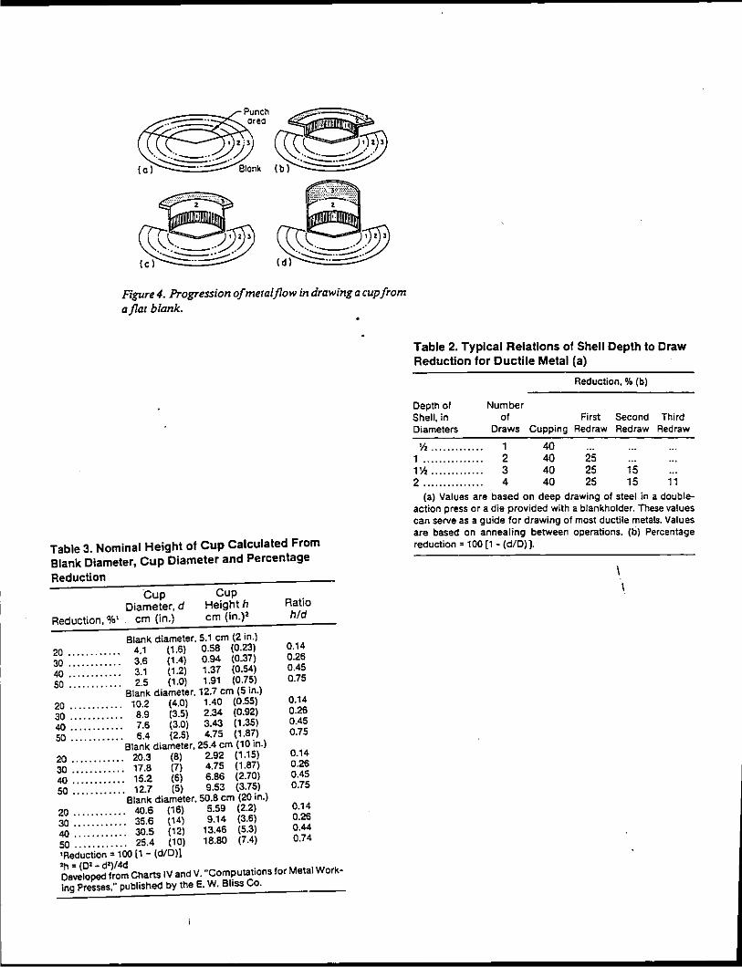
Figure4. Progression of meta/flow in drawing a cup from a flat blank.
Table 3. Nominal Height of Cup Calculated From Blank Diameter, Cup Diameter and Percentage
Reduction
Cup Diameter, d
Reduction, o/o1 em (in.)
Cup Heighth em (in.)'
Ratio hid
Blank diameter, 5.1 em {2 in.) 20 .. .. .. . .. . .. 4.1 (1.6) 0.58 (0.23) 0.14 30 . . .. . . . . . . . . 3.6 (1.4) 0.94 (0.37) 0.26 40 .. . .. ... ... . 3.1 (1.2) 1.37 (0.54) 0.45 50 . . . . . . . . . . . . 2.5 (1.0) 1.91 (0.75) 0.75
Blank diameter, 12.7 em (5 in.) 20 ............ 10.2 (4.0) 1.40 (0.55) 0.14 30 . . . . . . . . . . . . 8.9 (3.5) 2.34 (0.92) 0.26 40 . . . . . . . . . . . . 7.6 (3.0) 3.43 (1.35) 0.45 50 . . . . . . . . . . .. 6.4 (2.5) 4.75 (1.87) 0.75
Blank diameter, 25.4 em (10 in.) 20 ............ 20.3 (8) 2.92 (1.15) 0.14 30 ............ 17.8 (7) 4.75 (1.87) 0.26 40 . . . . . . . .. . . . 15.2 (6) 6.86 (2.70) 0.45 50 . . . . . . . . . . . . 12.7 (5) 9.53 (3.75) 0.75
Blank diameter. 50.8 em (20 in.) 20 ............ 40.6 (16) 5.59 (2.2) 0.14 30 . . . . . . . . . . . . 35.6 (14) 9.14 (3.6) 0.26 40 . . . . . . . . . . . . 30.5 (12) 13.46 (5.3) 0.44 50 . . . . . . . . . . . . 25.4 (10) 18.80 (7.4) 0.74 'Reduction= 100 [1- (d/D)j 'h = (0'- d')/4d Developed from Charts IV and V. "Computations for Metal Work~ ing Presses," published by the E. W. Bliss Co.
Table 2. Typical Relations of Shell Depth to Draw Reduction for Ductile Metal (a)
Reduction.% (b)
Depth of Number Shell, in of First Second Third Diameters Draws Cupping Redraw Redraw Redraw
1h ········· .... 1 40 1 ··············· 2 40 25 1\o\ ............. 3 40 25 15 2 ............... 4 40 25 15 11
(a) Values are based on deep drawing of steel in a doubleaction press or a die provided with a blankholder. These values can serve as a guide for drawing of most ductile metals. Values are based on annealing between operations. (b) Percentage reduction= 100 [1- (diD)].
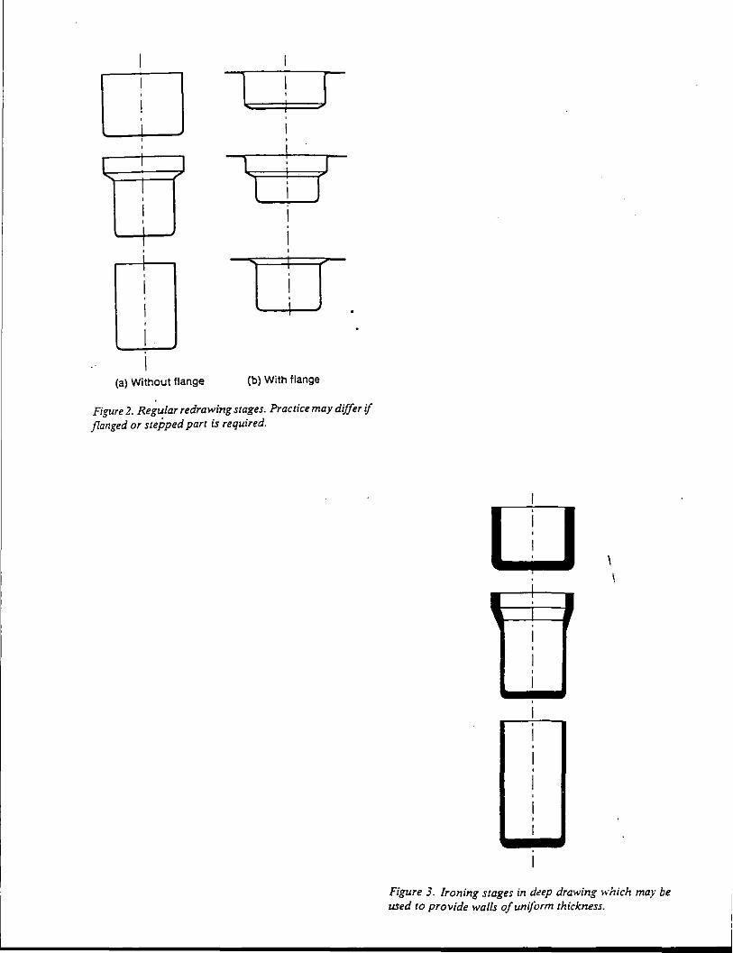
,--------- -- --
I I I ' I .. ¥
I
r I I 1 ' <
( l ..
I ' I I I ; :
I ;
(a) Without flange (b) With flange
Figure 2. Regular redrawing stages. Practice may differ if flanged or stepped parr is required.
i : I I
Figure 3. Ironing stages in d~ep drawing }~·hich ma.v be used to provide walls of uniform thickness.
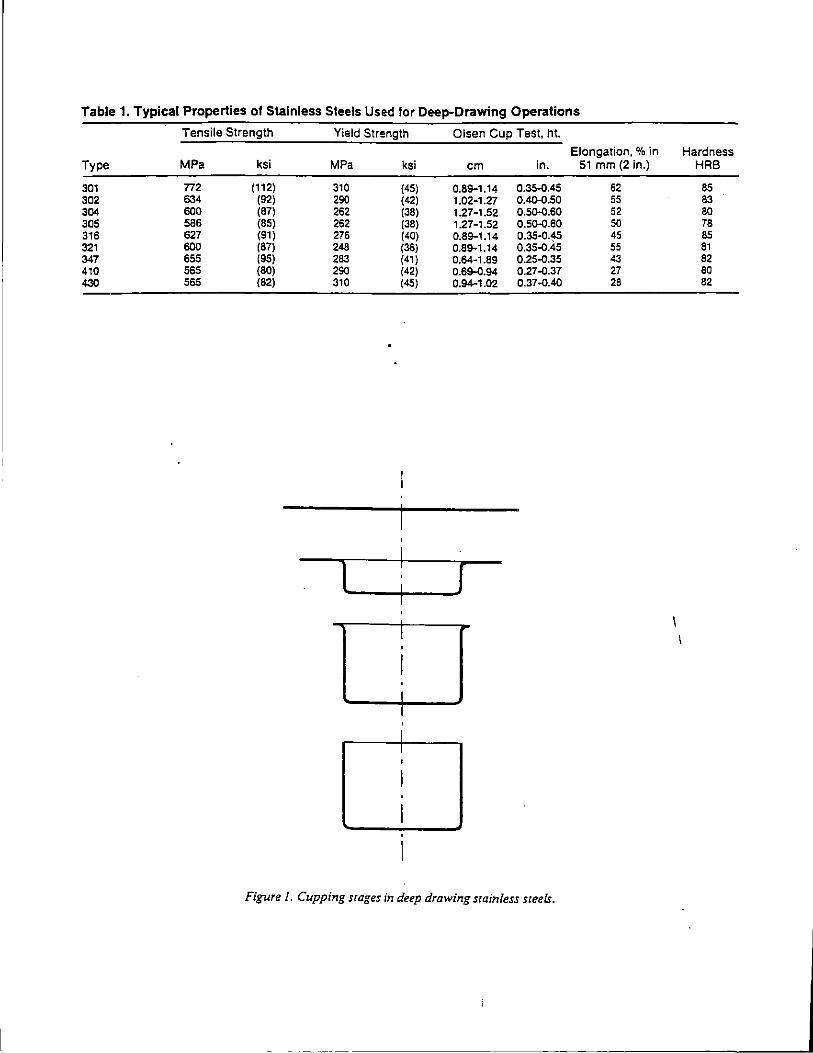
Table 1. Typical Properties of Stainless Steels Used lor Deep-Drawing Operations
Type
301 302 304 305 316 321 347 410 430
Tensile Strength
MPa ksi
772 (1 12) 634 (92) 600 (87) 586 (85) 627 (91) 600 (87) 655 (95) 565 (80) 565 (82)
Yield Strength
MPa
310 290 262 262 276 248 283 290 310
t
ksi
(45) (42) (38) (38) (40) (36) (41) (42) (45)
I •
I • I I . I I
'
Olsen Cup Test, ht.
em in.
0.89-1.14 0.35.0.45 1.02-1.27 0.4Q.0.50 1.27-1.52 0.50.Q.60 1.27-1.52 O.SO.Q.60 0.89-1.14 0.35.Q.~S 0.89-1.14 0.35.0.45 0.64-1.89 0.2S.Q.35 0.69-0.94 0.27.0.37 0.94-1.02 0.37.0.40
I
Figure/. Cupping srages in deep drawing stainless steels.
Elongation,% in 51 mm (2 in.)
62 55 52 50 45 55 43 27 28
Hardness HRB
85 83 so 78 65 81 82 80 82
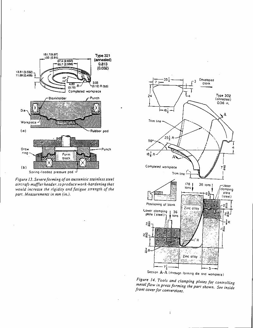
Draw nng
(b)
Spring-loaded pressure pad
Type 321 (annealed)
0.813 (0.032)
3.05 (0. 1 2) A (typ)
Punch
Figure 13. Severe forming of an austenitic srainle~s steel aircraft-muffler header. to produce work·hardemng th:t would increase the rigidity and fatigue strength oft e part. Measurements in mm (in.).
Trim line
Developed blank -
Type 302 (annealed) 0.016 in,
Section A-A (through forming die and workpiece)
Figure 14. Tools and clamping plates for controlling metal flow in press forming the parr shown. See inside front cover for conversions.
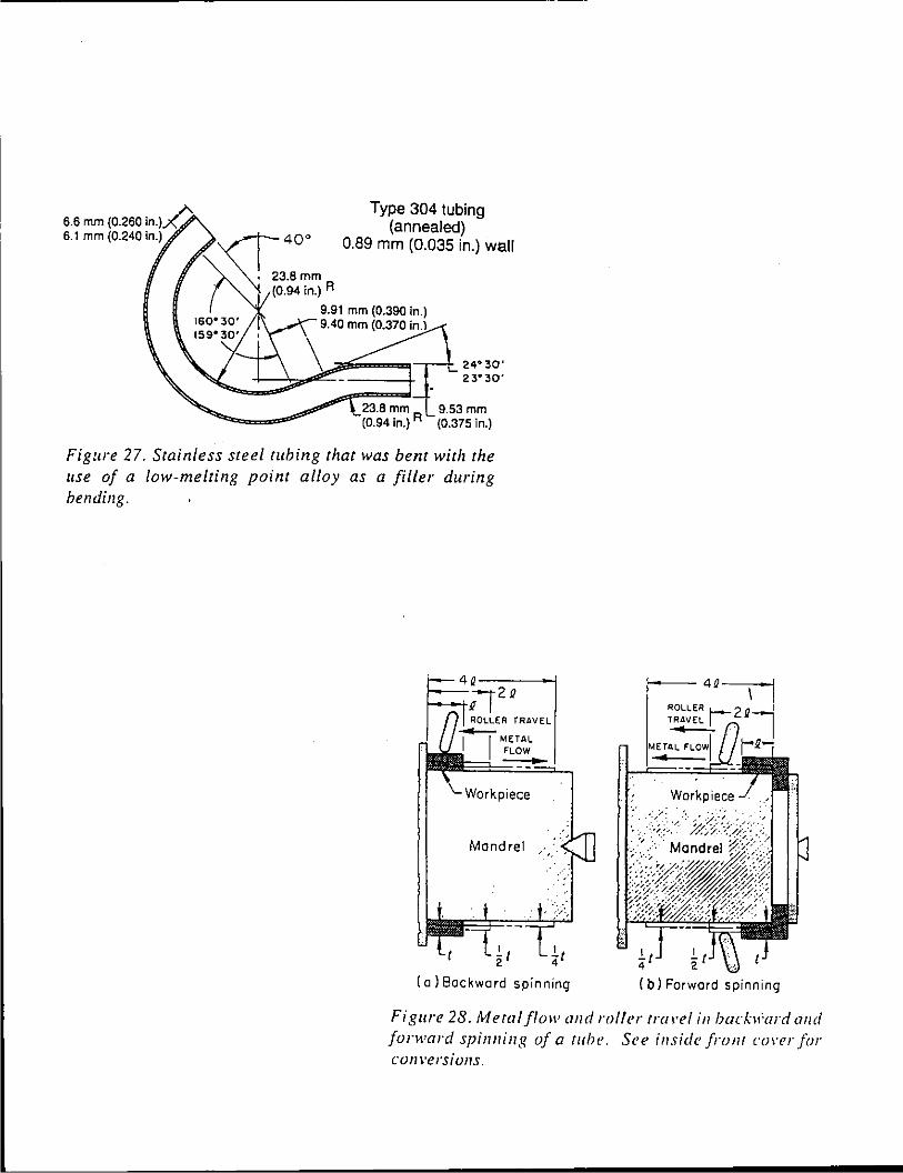
6.6 mm (0.260 in.)~ 6.1 mm (0.240 in.)
Type 304 tubing (annealed)
0.89 mm (0.035 in.) wall
9.53 mm (0.375 in.)
Figure 27. Stainless steel tubing that was bent with the use of a /ow-melting point alloy as a filler during bending.
R TRAVEL ,.;...__ METAL FLOW
Mandrel
!.t -'-t 2 4
(a) Backward spinning
;---- 4D---
-'-t 4
(b) Forward spinning
Figure 28. Meta/flow and roller tra•·el in bach'ard and forward spinning of a tuhe. See inside fro Ill cm·er fin· con versions.
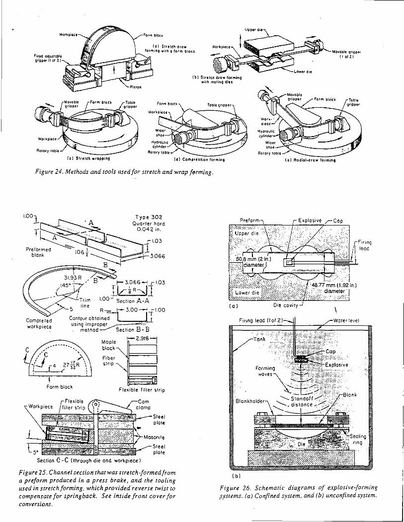
blOCk
(o) Slretcll draw formin9 with a farm blacll Mo~able ~ripper
( 1 ot 2)
(b) Slrelcll drowlarmin9 will\ molino; diu
Figure 24. Methods and tools used for stretch and wrap f~rming.
31.93 R
Type 302 Quarter hard
0.042 rn
1 ~~ t- 3.066--: r 1 03
/4:J7 ~k:~R-,J] - -7---L;,rrm 1 00 Sect1on A-A · >- l1ne / 5 R"' r300 [fi.OO
Comple red Contour obtained workpiece usrng 1m proper _..........-~,··
Form block
5'
method__.....- Sect1on 8-8
Maple >-- 2.9161
block""" 1
Fiber '.)~===::;1 Slrrp ~
,,~~~
Flexible filter strip
<'<---Steel plate
%;<'r:7-M.oson•le
Steel plate
Section C- C (through die and workpiece l
Figure 25. Channel section that was stretch-formed from a preform produced in a press brake, and the tooling used in strerchforming, which provided reverse twist to compensate for springback. See inside front cover for conversions.
(e) Radial-draw larmino;
Preform 1
(o) Die cavity
Sla okhold<or-.,
(b)
Figure 26. Schematic diagrams of explosive-forming eYStems. (a) Confined system, and (b) unconfined system.
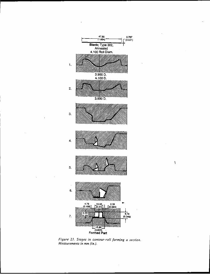
47.85 0.787 r-----11.8&4) ___ _,1 (0031)
Blank; Type 302, T Annealed
4.100 Roll Diam.
1.
2.
3.
4.
5.
6.
7.
Figure 23. Stages in contour-roll formfng a section. Measurements in mm (in.).
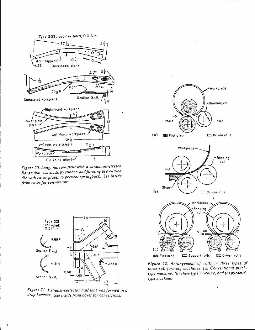
Type 302, quarter herd, 0.016 in.
37.!...!. 64
blank
Completed workpiece
Left-hand workpiece >------- 38 ~ _____ _,
Cover plate (steel} 2t
Die (zinc alloy)-'
Figure 20. Long, narrow strut with a contoured-stretch flange that was made by rubber-pad forming in a curved die with cover plates to prevent springback. See ms1de front cover for conversions.
Type 321 (ann~~aled) 0.0 ~2 in.
l.0.89R Secl,on ll- 8
( -UIR
Section 1\- A
Figure 21. Erhaust-collecror half that was formed in a drop hamm('r. See inside front cover for conversions.
""IIONT
( 0 l lil1 Flat oreo
Workpiece
(b)
Workpiece
D Driven rolls
Bending roll
D Driven rolls
m Flat area 0 Support rolls c:J Driven rolls
Figure 22. Arrangement of rolls in three types of three-roll forming machines. (a) Conventional pinchtype machine, (b) shoe-type machine, and (c) pyramidtype machine.
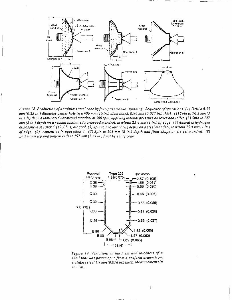
Wooo j rnanorel- I
1 Operohon 3 . l
-2-!_;_1
Operohon a
t_, __ ,
,.
Type 305 (dnn~oledl
S.C:!i r..
Ooera11an ~
Comote rrd · .. orkc,ece
Figure 18. Production of a stainless steel cone by four-pass manual spinning. Sequence of operations: ( 1) Drill a 6.35 mm (0.25 in.) diameter center hole in a 406 mm ( 16 in.) diam blank. 0.94 mm (0.037 in.) thick. (2) Spin to 76.2 mm (3 in.) depth on a laminated hardwood mandrel at 300 rpm, applying manual pressure on lever and roller. (3) Spin to 127 mm (5 in.) depth on a second laminated hardwood mandrel, to within 25.4 mm (I in.) of edge. (4) Anneal in hydrogen atmosphere at 104o•c ( 1900°F); air cool. (5) Spin to 178 mm (7 in.) depth on a steel mandrel, to within 25.4 mm ( 1 in.) of edge. (6) Anneal as in operation 4. (7) Spin to 203 mm (8 in.) depth and final shape on a steel mandrel. (8) Lathe-trim top and bottom ends to 197 mm (7.75 in.) final height of cone.
Rockwell Type 302 Thickness Hardness 1.91 (0.075) ~ r-2.67 (0.105)
c 38 _,,,.., --'-----=:;,r 1.55 (0.061) c 39 - "! 0.66 (0.026)
C39-.
C39-·
305 (12) C38-·
C36-!
-u-0.66 (0.026)
0.66 (0.026)
0.69 (0.027)
8 96 _/ .. . 1.65 (0.065)
8 99 _/ I 1.57 (0.062} B 98..J L 1.65 (0.065)
1-- 152 (6) ----1
Figure 19. Variations in· hardness and thickness of a shell that was power-spun from a preform drawn from stainless stee/1.9 mm (0.078 in.) thick. Measurements in mm (in.).
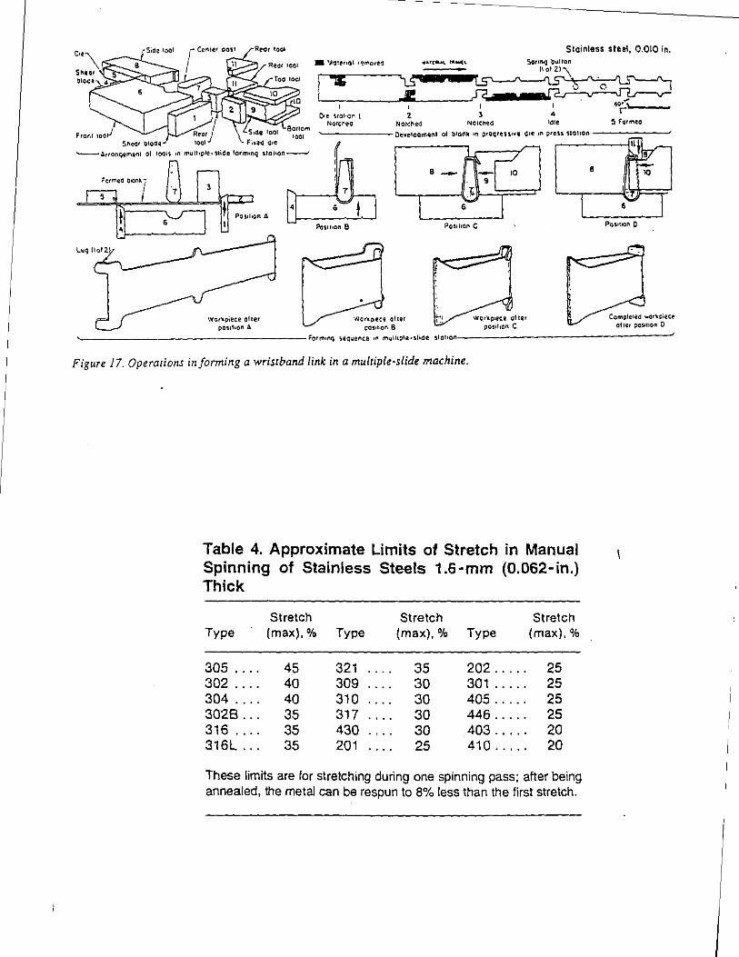
Stainless steel, 0.010 in.
-A~ronqement of toots '" muthple.sticSe lotmonq stouon---'
Workoiece of ter posotoon A
O•e stot•OI'1 t Notc~eo Notched
WQrkl)•ece ol!er C:OS•I•Qn 8
t •
,.-
1'1~ ~ - - 10 9
>: •"""' I
P0~1to0n C
'•i
Figure 17. Operations informing a wristband link in a multiple-slide machine.
Table 4. Approximate Limits of Stretch in Manual Spinning of Stainless Steels 1.6-mm (0.062-in.) Thick
Stretch Stretch Stretch Type (max),% Type (max),% Type (max).%
305 45 321 35 202 ..... 25 302 40 309 30 301 ..... 25 304 40 310 30 405 ..... 25 3028 ... 35 317 30 446 ..... 25 316 .... 35 430 30 403 ..... 20 316l ... 35 201 25 410 ..... 20
These limits are for stretching during one spinning pass; after being annealed, the metal can be respun to 8% less than the first stretch.
•
Posotoon 0
Compte•eo workoiete ofter posouon 0
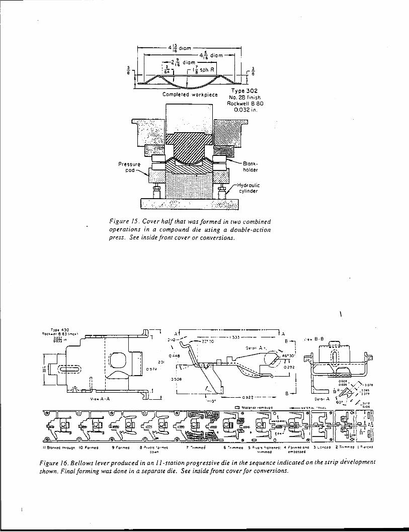
tl Blono.~e~ r~rou9n !0 For,.,ea
'----- 15 ---------1 r 4 i6 dtom
,-lrlvcJ•oulic cylinder
Figure 15. Cover half that was formed in two combined operations in a compound die using a double·ac:tion press. See inside front cover or conversions.
9 F'crmed 9 l>,.,ers '.l<"'e'l ~~ .. n
\
0449
::>508
6 ~''"'"'ta 5 =>-vor~ llarte~~d; <I F~rmeo ana 3 l:nc~o Z ;,...,..,~., l =,.,,,!d "''"meCI ~moc,sed
Figure 16. Bellows lever produced in an JJ.station progressive die in the sequence indicated on the strip dfvelopment shown. Final forming was done in a separate die. See inside front cover for conversions.
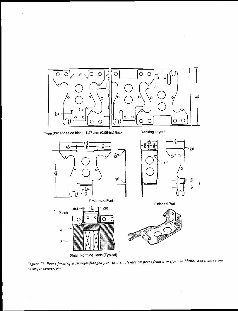
0 0
• 0 0 0 0
0 0 0
0 0
Type 302 annealed blank, 1.27·mm (0.05-in.) thick
9 Oi6
u Preformed Part
Finish Forming Tools (Typical)
0 0 0 0
0 0
0 0
0 0
0 0
Blanking Layout
•
0 0
Finished Part
'
Figure 12. Press forming a straight-flanged part in a single·action press from a preformed blank. See inside front
cover for conversions.
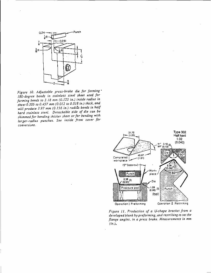
Figure 10. Adjustable press-brake die for forming· 180-degree bends in stainless steel sheet used for forming bends to 3.18 mm (0.125 in.) inside radius in sheet 0.305 to 0.457 mm (0.012 to 0.018 in.) thick, and wi/J produce 3.97 mm (0.156 in.) radius bends in half hard stainless steel. Detachable side of die can be shimmed for bending thicker sheet or for bending with larger·radius punches. See inside front cover for
conversions.
Type 302 Half hard
1.02 (0.040)
Qperorion 2 Restriking
Figure I 1. Production of a U-shape bracket from a developed blank by preforming, and restriking to set the flange angles. in a press brake. t'vleasurements in mm (in.).
-
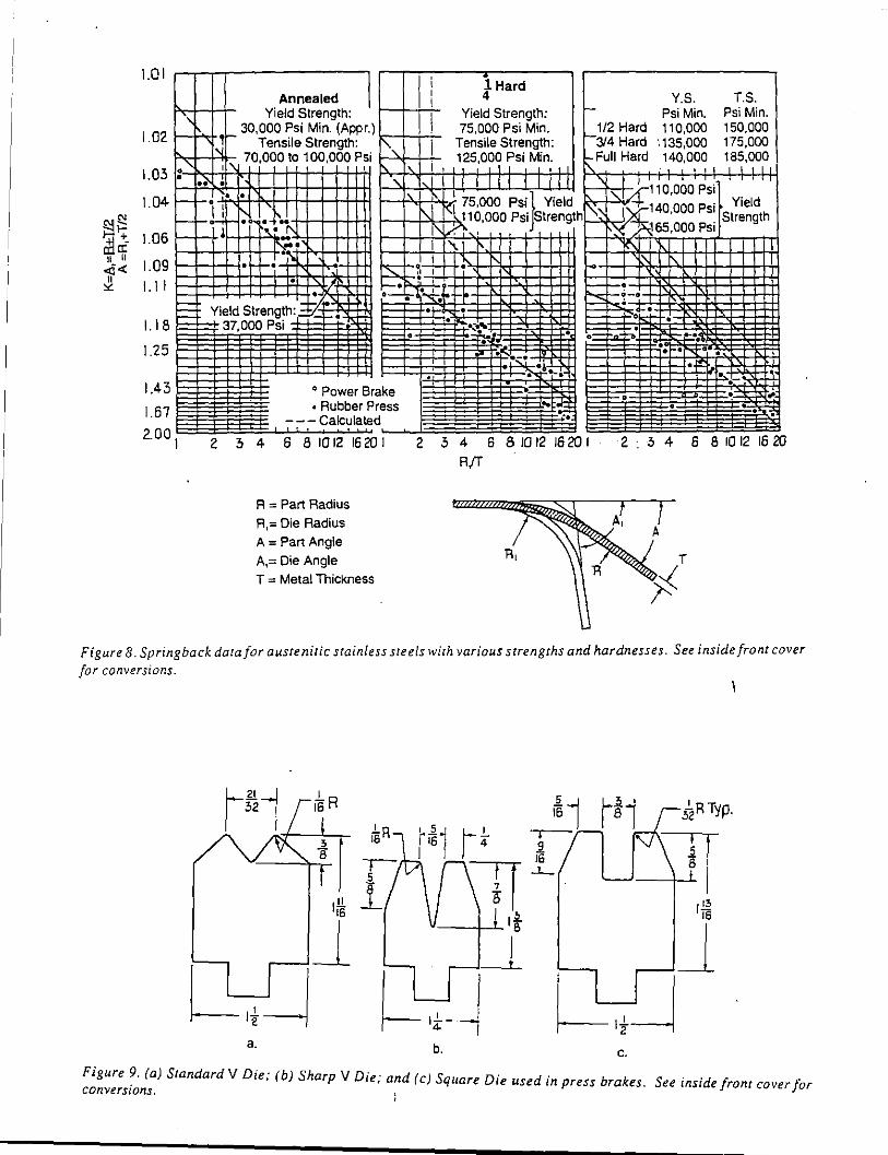
1.0 I ,.-,--.-..,.-------,~ ,...-.,.-,....,---..---}-----, ,------------. 1
Hard Annealed Y.S. T.S.
,, Yield Strength: 1--+-+-i- Yield Strength: f- Psi Min. Psi Min. r 30,000 Psi Min. (Appr.)k-+-ir+- 75,000 Psi Min. f-~~~ Hard 110,000 150,000
1.02 f-'NIJ Tensile Strength: "" Tensile Strength: 1 "'"'Hard 1135,000 175,000 P"<:+-+-11
11>:-, 70,000 to 100,000 Psi 1--"1---+-'- 125,000 Psi Min. f.-Full Hard 140,000 185,000
J.03 :~--l'-c+-Tf-'"!.-i-1-J--1-++-1-+-J+H f'.:--N+f-+f-+t+f-1 --f-f-H-H • o I I. I I I .'\ 1
1 I , I ~ 10,000 . ..;_, •• •
1.04 f-f-• ," • 1--+'-+-7'<t:.<J;o~gg0 Psi Yield !'\~· ' ~~"n.oo~ ~:; Yield I-_Ji • ". ~:.b<+H-+14-H 1--+-l-"hf-i~~~, PSI '"""\!" ~"'< ; nnl) Psi
1.06 r-:;.. ~ • ~~· 1---+-~~~-+~+-+-~+H
I 1.09
I. I I
E= 1.18 1--
1.25
1.43
1.67
2.00 I 2
. ' 0 .o-;-, I
37,000 Psi
o Power Brake • Rubber Press
, , - Calculated
3 4 6 8 10 12 16 20 I
R = Part Radius R,= Die Radius A = Part Angle A.= Die Angle T = Metal Thickness
2 3 4 6 81012 16201 2 R/f
Rl
Figure 8. Springback datafor austenitic stainless steels with yarious strengths and hardnesses. See inside front cover for conversions.
c. a. b.
Figure 9. (a) StandardV Die; (b) Sharp V Die; and (c) Square Die used in press brakes. converswns. ; See inside fronr cover for
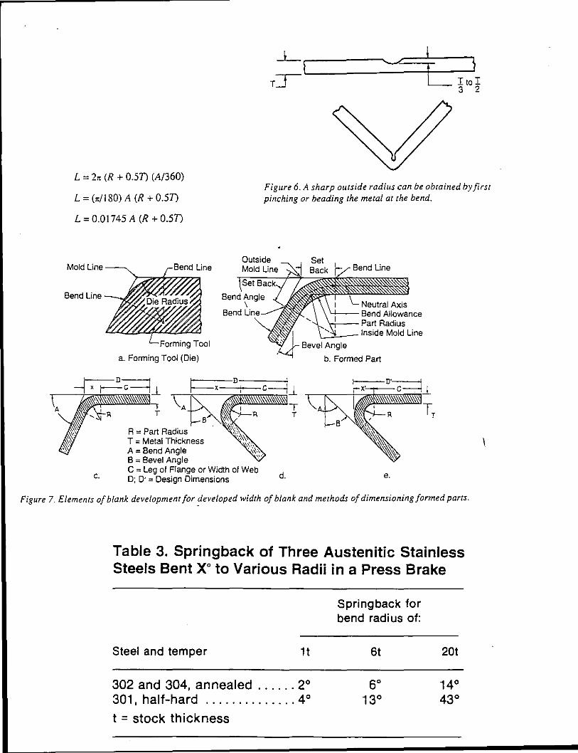
_j_ '\ ----...__.,
TT
L = 2~ (R + 0.51) (A/360)
L = (~/180) A (R + 0.51)
L = 0.01745 A (R + 0.51)
Figure 6. A sharp outside radius can be obrained byfirsr pinching or beading the metal at the bend.
Mold Line
c.
a. Forming Tool (Die)
R = Part Radius T = Metal Thickness A = Bend Angle B = Bevel Angle C = Leg of Flange or Width of Web D; D· = Design Dimensions d.
Neutral Axis '-'-- Bend Allowance \+--Part Radius
L-,___lnside Mold Line
e.
Figure 7. Elemenrs of blank development for developed width of blank and mer hods of dimensioning formed parts.
Table 3. Springback of Three Austenitic Stainless Steels Bent xo to Various Radii in a Press Brake
Steel and temper 1t
302 and 304, annealed ...... 2° 301, half-hard .............. 4°
t = stock thickness
Springback for bend radius of:
6t 20t
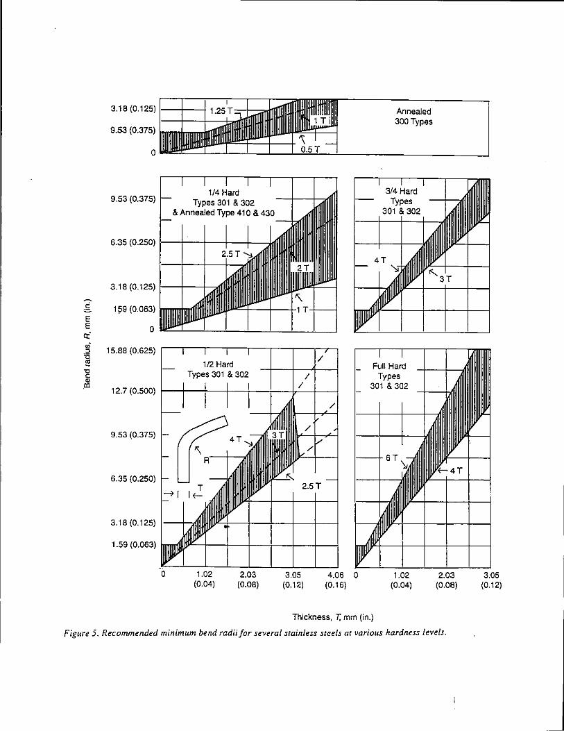
:§. E E a: .,; :J '0 ['!
"C c " .ca
3.18 (0.125) 1--+--l
9.53 (0.375)
0
9.53 (0.375)
3.18 (0.125)
1 ?9 (0.063)
0
15.88 (0.625)
12.7 (0.500)
9.53 (0.375)
6.35 (0.250)
3. 18 (0.125)
1.59 (0.063)
0 1.02 (0.04)
2.03 (0.08)
3.05 (0.12)
4.06 0 (0.16)
Annealed 300 Types
Full Hard Types
301 & 302
1.02 (0.04)
Thickness, T. mm (in.)
2.03 (0.08)
Figure 5. Recommended minimum bend radii for several stainless steels at various hardness levels.
3.05 (0.12)
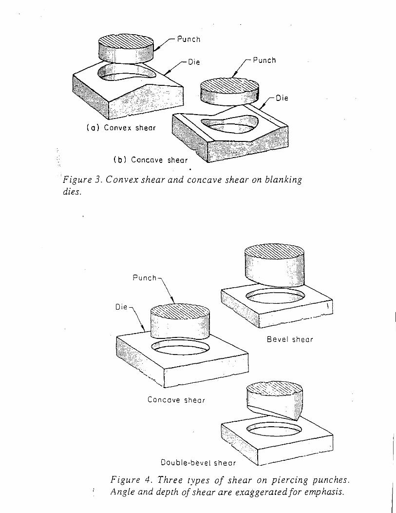
Punch
Die Punch
Die
(o) Convex shear
(b) Concave shear
Figure 3. Convex shear and concave shear on blanking dies.
Punch
Bevel shear
Concave shear
Double-bevel shear
Figure 4. Three types of shear on piercing punches. Angle and depth of shear are exaggerated for emphasis.
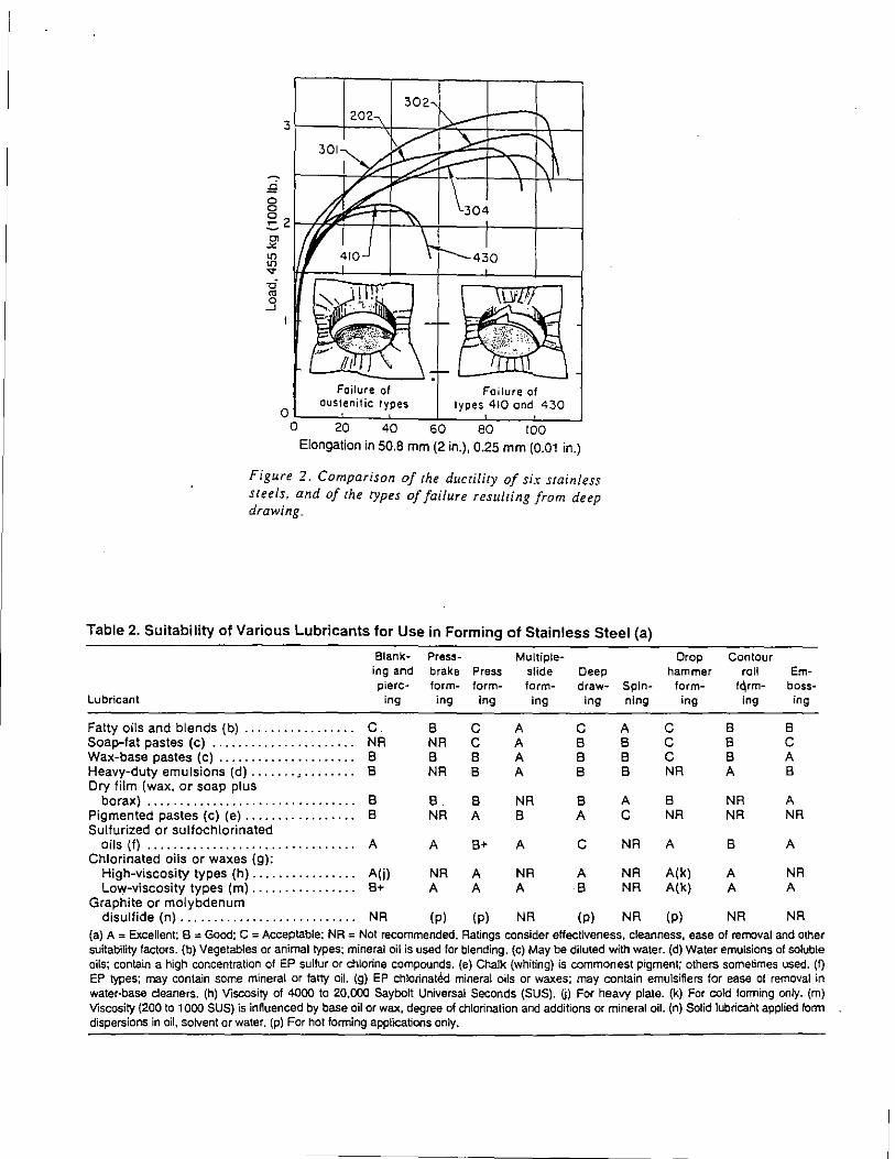
Failure of Failure of austenitic types types 410 end 430
00~~~--~--~--~~~~~ 20 40 60 80 100
Elongation in 50.8 mm (2 in.), 0.25 mm (0.01 in.)
Figure 2. Comparison of the ductility of six stainless steels, and of the types of failure resulting from deep drawing.
Table 2. Suitability of Various Lubricants for Use in Forming of Stainless Steel (a)
Blank· Press- Multiple-ing and brake Press slide Deep pierc- form- form- form- draw- Spin-
Lubricant ing ing ing ing ing ning
Fatty oils and blends (b) ................. c 6 c A c A Soap-fat pastes (c) ...................... NR NR c A 6 6 Wax-base pastes (c) ..................... 6 6 6 A 6 6 Heavy-duty emulsions (d) ....... , ........ 6 NR 6 A 6 6 Dry film (wax, or soap plus
borax) ................................ 6 6 6 NR 6 A Pigmented pastes (c) (e) ................. 6 NR A 6 A c Sulfurized or sulfochlorinated
oils (f) ......•......................... A A 6+ A c NR Chlorinated oils or waxes (g):
High-viscosity types (h) ................ A(j) NR A NR A NR Low-viscosity types (m) ......•.......•. 6+ A A A 6 NR
Graphite or molybdenum disulfide (n) ........................... NR (p) (p) NR (p) NR
Drop Contour hammer roll Em-
form- f~rm- boss-ing ing ing
c 6 6 c 6 c c 6 A NR A 6
6 NR A NR NR NR
A 6 A
A(k) A NR A(k) A A
(p) NR NR (a) A = Excellent; 8 = Good; C = Acceptable: NR = Not recommended. Ratings consider effectiveness, cleanness, ease of removal and other suitability factors. (b) Vegetables or animal types: mineral oil is used for blending. (c) May be diluted with water. (d) Water emulsions of soluble oils; contain a high concentration of EP sulfur or chlorine compounds. (e) Chalk (whiting) is commonest pigment; others sometimes used. (f) EP types; may contain some mineral or fatty oil. (g) EP chlorinat~ mineral oils or waxes: may contain emulsifiers for ease of removal in water-base cleaners. (h) Viscosity of 4000 to 20,000 Saybolt Universal Seconds (SUS). ij) For heavy plate. (k) For cold forming only. (m) Viscosity (200 to 1000 SUS) is innuenced by base oil or wax, degree of chlorination and additions or mineral oil. (n) Solid lubricalit applied fonn dispersions in oil, solvent or water. (p) For hot forming applications only.

Table 1. Relative Suitability of Stainless Steels for Various Methods of Forming (a)
Suitability for:
Yield Press· strength, brake Deep Roll
0.2'14> offset, form- draw- Spin- ·rorm- Emboss-Steel MPa ksi Blanking Piercing ing ing ning ing Coining lng
Auatenltlc Steel1 201 ................ 379 55 8 c 8 A-8 C-D 8 8-C 8-C 202 ................ 379 55 8 8 A A 8-C A 8 8 301 ................ 276 40 8 c 8 A-8 c-o 8 8-C 8-C 302 ................ 255 37 8 8 • A A 8-C A 8 8 3028 ............... 276 40 8 8 8 8-C c c 8-C 303, 3035e ......... 241 35 8 8 O(b) 0 D D C-D c 304 ................ 241 35 8 8 . A A 8 A 8 R 304L ............... 207 30 8 8 A A 8 A 8 b 305 ................ 255 37 8 8 A 8 A A A-8 A-8 308 ................ 241 35 8 8(b) D D D D 309,3095 ........... 276 40 8 8 A(b) 8 c 8 8 8 310,3105 .......... 276 40 8 8 A(b) 8 8 A 8 8 314 ................ 345 50 8 8 A(b) 8-C c E: 8 8-C 316 ................ 241 35 8 8 A(b) 8 8 A 8 8 316L ............... 207 30 8 8 A(b) 8 8 A 8 8 317 ...... : .. ....... 276 40 8 8 A (b) 8 8-C 8 8 8 321, 347, 348 ....... 241 35 8 8 A 8 8-C 8 8 8 384, 385 ............ 241 35 8 8 A A-8 A A A-8 A-8
Martenaltlc Steels 403, 410 ............ 276 40 A A-8 A A A A A A 414 ................ 655 95 A 8 A(b) 8 c c 8 c 416, 416Se ......... 276 40 8 A-8 C(b) D 0 D D c 420 ................ 345 so 8 8-C C(b) C-D 0 c-o C-D c 431 ................ 655 95 C-D C-D C(b) C-D D C-D C-D C-D 440A ............... 414 60 8-C C(b) C-D 0 C-D D c 4408 ................ 427 62 0 D D 440C ............... 448 65 D D D
FerrUle SttMis 405 ................ 276 40 A A-8 A(b) A A A A A 409 ................ 255 37 lr' A-8 A(b) A A A A A 429 ................ 310 45. A A-8 A(b) A-8 A A A A 430 ................ 310 45 A A-8 A(b) A-8 A A A A 430F ............... 379 55 8 A-8 A(b) A-8 A A A A 430F 5e ............ 379 55 8 A-8 8-C(b) D D D C-D c 434 ................ 393 57 8 A-8 8 8 8 8 A-8 A-8 436 ................ 393 57 8 A-8 8 8 8 8 A-8 A-8 442 ................ 345 50 A A-8 A(b) 8 8-C A 8 8 446 ................ 345 so A 8 A(b) 8-C c 8 8 8
(a) A, Excellent; 8, Good; C, Fair; 0, Not generally recommended. Suitability ratings are based on comparison of the steels within any one class; thus it should not be inferred that a ferritic steel with an A rating is more formable than an austenitic steel with a C rating for a particular method. (b) Severe sharp bends should be avoided.
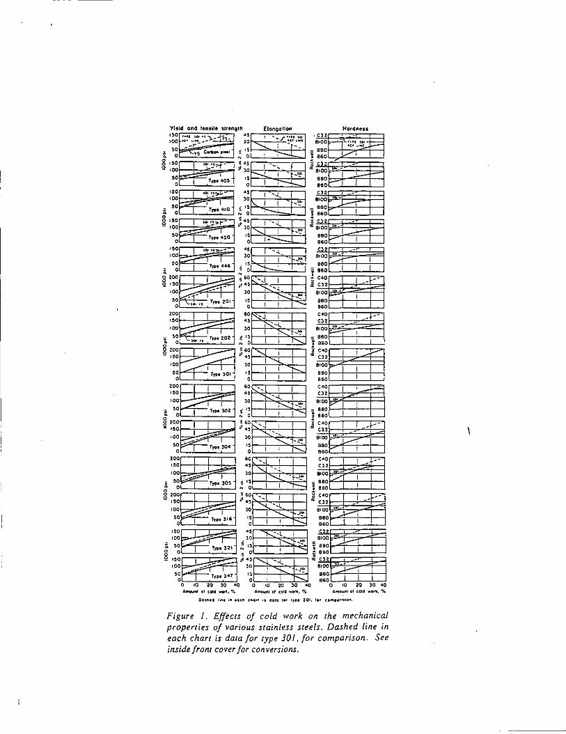
ro-c •G••t).~ ..... ~. ii ' __ ,..- '
:~. i 5~ g
Cu-11eoo1
:I ·~· :!~- _J g •oo
._ -' :r r,, 40~ 00
0
:I "0 •co
i ~~ g
:I "0 100
g
--
"·' '.!,....-
' I r, .. , 410
'"' '.!'>ri
TJIJI 1
4~0 ;r 00 0
:I •oo 100
50
& 0 8 200 Q 1,0 I
If!!,,,_-
TI'PI !446 ~
I -'-o::: -•CO
00 0
-:;., ---" ---I I_
200
"0 •CO
;. ~~
.,_-,., .. I .....,...
'- .... ,,
r,,. 201
I I
I I TJPO 202
§~~~~ •CO
'~ -1 r,,. ~or
:~~~ •co
i s~ TJfMI 302
~ ~~ 0 I
•O 50
0 o I -f-::"'_;p-
-0
0 0
20
" •o 0
0 0
~ 5
I ·;....----
r,, ~04
I -
' r,... 30'
§:~~~ 5~~
Amoo.nr cr cold -'· ~.
~f±J -H. 1=~~-~--~ ~
lO I - •• IS I -.,
0 I I
•o_~~ i •o ~0 I '-.l...
.-'!' " I~ ' .::, 0 I I j
~=~im- :i lO I IS I I o I I
=~~' .. : lO I~---
§ ·~ ' ' "' 0 I I I ! ;;~~-I :
30 .... l.. I ,~
1
~ I I
Hardness Cl2 -
8100 ri\.;;:r .. ~t.:t::==l 880 . B60 I 1
Cl::! -810~r -
I I
==~~- I Cl2 ' -
8100 ' -880 ' BiO I Cl -8100
I ::~p I I
'" - ' 8t00 . ::~I
I I I
c•o
'" -I -f--
--8100 I
880 BiO I
c<O I ---"' -8100 .. -880
;;o-, I
BiO I
c<O I ' Cl2
8100 I
880 BiO I
c<O I ' -Cl2
8100 .. 880
! BiO I I e<O I I ir--Cl2 -
a•oo . -880 l--· I BiO I I e<O I I -+--Cl2 -•oo .. 880
/f I
BiO I I I e<O I I --Cl2 --••oo .. -880
J.--; 860
I
Cl -BIO~r
... j.--,
::~r I I Cl2 -
8100 ><•
.. o ~. I I I e&O
01020J000 A""c'"" cl calc! ••••. "to
Figure I_ Effects of cold work on the mechanical properties of various stainless steels. Dashed line in each chart is data for type 301, for comparison. See inside front cover for conversions.
_ _j
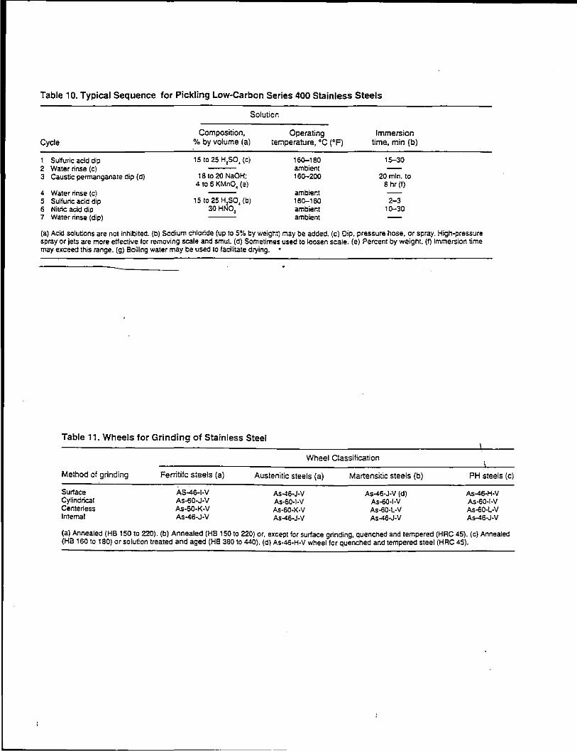
Table 1 0. Typical Sequence for Pickling Low-Carbon Series 400 Stainless Steels
Cycle
1 Sulfuric acid dip 2 Water rinse (c) 3 Caustic permanganare dip (d)
4 Water rinse (c) 5 Sulfuric acid dip 6 Nitric acid dip 7 Water rinse (dip)
Solutior.
Composition, % by volume (a)
15 to 25 H,so, (c)
18 to 20 NaOH: 4 to 6 KMnO~ (~)
15 to 25 H,so, (b) 30 HNO~
Operating ter:1perature, oc r:F)
16Q-180 ambient 16Q-200
ambient 16Q-180 ambient ambient
Immersion time, min (b)
15-30
20 min. to 8 hr (I)
2-3 1Q-30
(a) Acid solutions are not inhibited. {b) Sodium chloride (up to 5% by weight) may be added. (c) Dip, pressure hose, or spray. High-pressure spray or jets are more effective tor removing scale and smut. (d) Sometimes used to loosen scale. (e) Percent by weight. (f) Immersion time may exceed this range. (g) Boiling water may be used to facilitate drying.
Table 11. Wheels for Grinding of Stainless Steel
Wheel Classification
Melhod of grinding Ferritifc steels (a) Austenitic steels (a) Martensitic steels (b)
Surface Cylindrical Centerless Internal
AS-46-t·V As-60·J·V As·60·K·V As-46-J·V
As-46-J·V As·6Q.I.V As·60·K·V As-46-J-V
As-46·J·V (d) As·60-t·V As.OO·L·V As-46~J~V
PH steels (c)
As-46-H·V As·60·l·V As·60·L·V As-46-J~V
(a) Annealed (HB 150 to 220). (b) Annealed (HB 150 to 220) or. except for surface grinding. quenched and tempered (HRC 45). {c) Annealed (HB 160 to 180) or solution treated and aged (HB 380 to 440). (d) As-46-H.Y wheel for quenched and tempered steel (HRC 45).
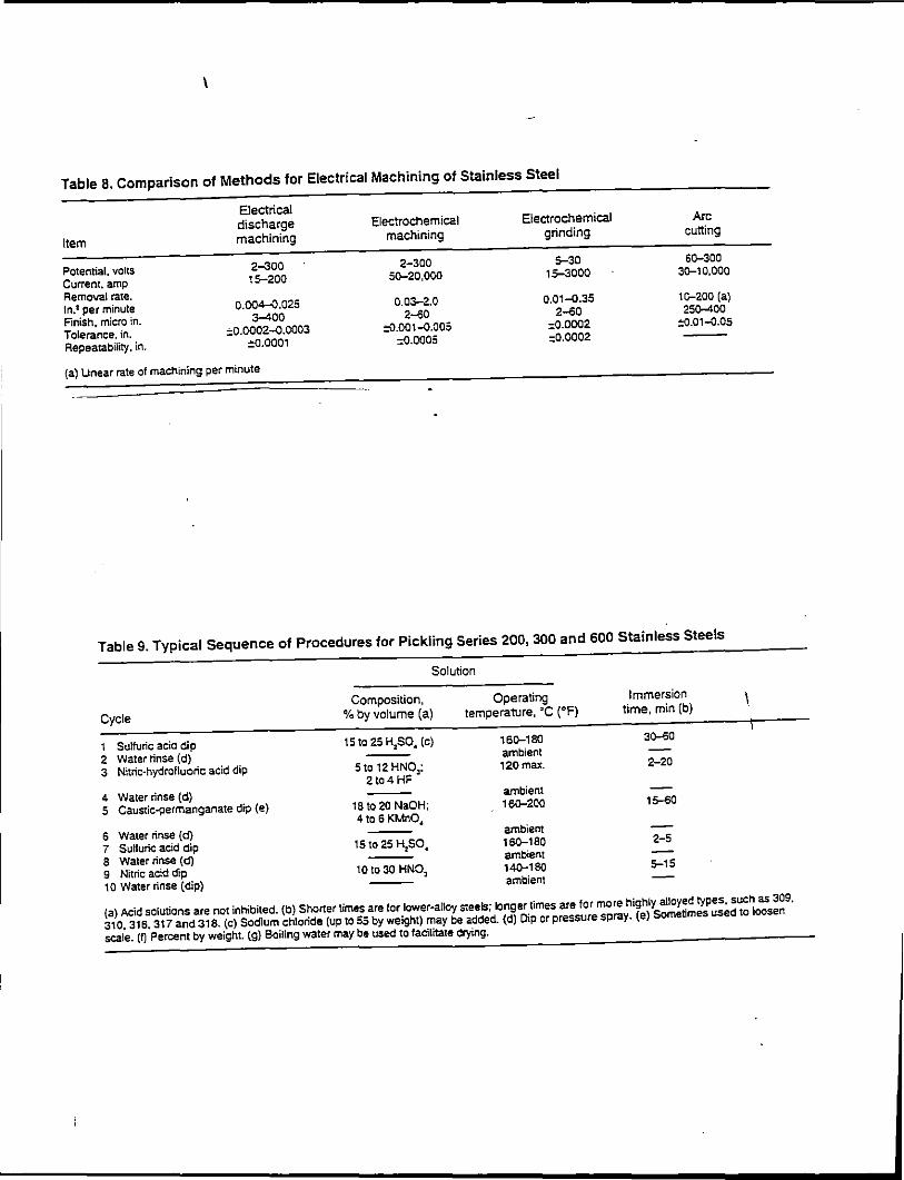
\
Table a. Comparison of Methods for Electrical Machining of Stainless Steel
Item
Potential, volts Current, amp Removal rate. ln.3 per minute Finish. micro in. Tolerance. in. Repeatability, in.
Electrical discharge machining
2-300 15-200
0.004-0.025 3-400
::0.0002-0.0003 ::::0.0001
(a) Unear rate of machining per minute
Electrochemical machining
2-300 5Q-20.000
0.03-2.0 2-60
::0.001-0.005 =0.0005
Electrochemical grinding
5-30 15-3000
0.01-0.35 2-<;0
:0.0002 :0.0002
Arc cutting
6Q-300 JQ-10,000
1c-200 {a) 25()-400
::0.01-0.05
Table 9. Typical Sequence of Procedures for Pickling Series 200, 300 and 600 Stainless Steels
Cycle
t Sulfuric acid dip 2 Water 'rinse (d) 3 Nitric-hydrofluoric acid dip
4 Water rinse {d) 5 Caustic-permanganate dip (e)
6 Water rinse (d) 7 Sulfuric acid dip 8 Water rinse (d) 9 Nitric acid dip 10 Water rinse (dip}
Solution
Composition, Operating
% by volume (a) temperature, 'C ('F)
151o 25 H,SO, {c) 16Q-180 ambient
5 to 12 HNOl; 2to4HF
120max.
ambient t8 to 20 NaOH; 16Q-200 4to 6 KMnO,
ambient 15 to 25 H250, 160-t80
ambient tO to 30 HNOl 140-180
ambient
Immersion time, min (b)
3D-<;O
2-20
15-<;0
2-5
5-15
(a) Acid solutions are not inhibited. (b) Shorter times are for lower-alloy s<eels; longer times are for more highly alloyed types, such as 309, 310, 316,317 and 318. (c) Sodium chloride (up to 55 by weight) may be added. (d) Dip or pressure spray. (e) Sometimes used to loosen scale. (f) Percent by weight. (g) Boiling water may be used to facilitate drying.
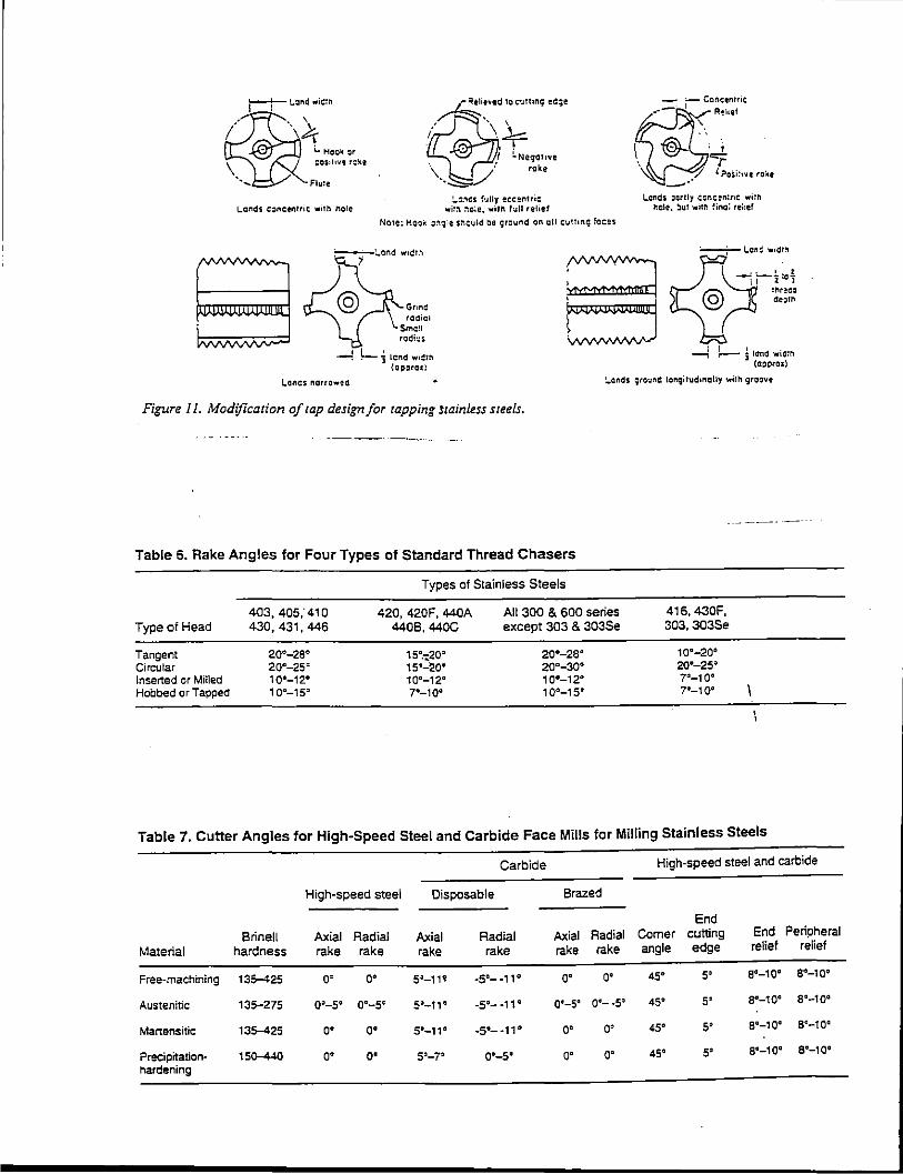
i
t=J-"'~""
i.. Moo~ ~r QOS;hV'! r:K!
Flu:e
Lands c:~neentric w•Tl'l noTe
;P!t~' ;:·~~:.::·· ~ "k'
;.:.,cs fully eccentric wit:.. :-:c;e, wirn full relief
NoTe: Hoc~ ::'l:;ie s~culd be ground on all c;uT:•nq feces
~';.and w1dt.~
--! ~ Jlcnd wi~rr. (OI)QtOl)
~. ; ,"~"::'
l ~oSi:,.,,e rolo.e ~
l..cnds ~ortly ccr11:en:ric: wi:n l:cle, ~uT witfl ~ina; rei:ef
~'~;~;,~ w '"" --1 1- J lend wid:!'!
(OCICitO:r.}
l.oncs narrowed :.ends qro1.1nd longitud•naUy with groove
Figure I I. Modification of tap design for tapping Stainless steels.
Table 6. Rake Angles for Four Types of Standard Thread Chasers
Type of Head
Tangent Circular Inserted or Milled Hobbed or Tapped
403,405,"410 430,431,446
20'"-28" 20"-25= 10"-12" 1 0"-15~
Types of Stainless Steels
420,420F,440A 4408. 440C
15"-20" 15;..::20" 10"-12" 7"-10"
All 300 & 600 series except 303 & 303Se
20"-28" 20"-30" 10"-12" 10"-15=
416, 430F, 303,303Se
10"-20" 20"-25~
7"-1 0" 7"-10"
Table 7. Cutter Angles for High-Speed Steel and Carbide Face Mills for Milling Stainless Steels
Carbide High-speed steel and carbide
High-speed steel Disposable Brazed
End Brinell Axial Radial Axial Radial Axial Radial Comer cutting End Peripheral
Material hardness rake rake rake rake rake rake angle edge relief relief
Free-machining 135-425 0' o• s~-1111 -5"--11" o· o• 45' 5' 8"-10" 8"-10"
Austenitic 135-275 oo-so a~~-s~ 5'-11° -s~~- _,," oe-sa 0"-·5' 45' 5' 8"-10" 8"-10"
Martensitic 135-425 o• o• 5"-11" -5"- -11° 0' 0' 45' 5' 8"-10° 8"-10"
Precipitation- 15Q-.4.10 o• o· 5'-7" 0"-5' o· 0' 45' 5' 6"-10" 8"-10"
hardening
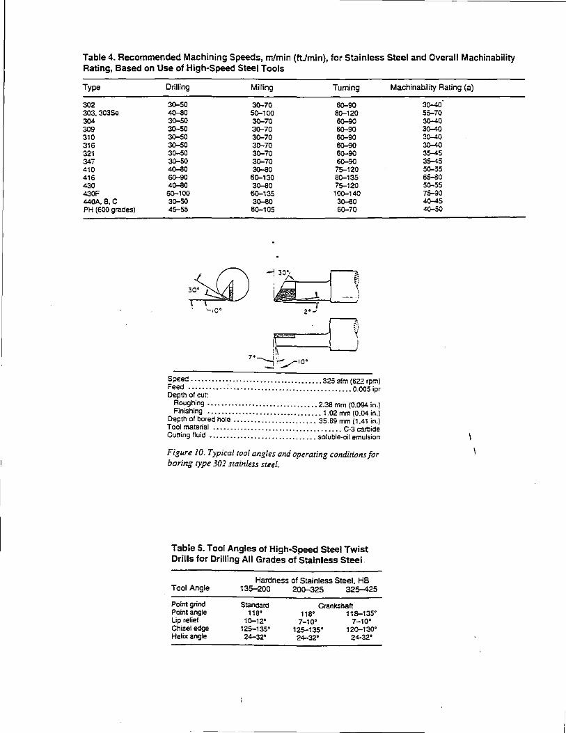
Table 4. Recommended Machining Speeds, m/min (ftJmin), for Stainless Steel and Overall Machinability Rating, Based on Use of High-Speed Steel Tools
Type
302 303, 303Se 304 309 310 316 321 347 410 416 430 430F 440A, e.c PH (600 grades)
Drilling Milling Turning
3D-50 3Q-70 6Q-90 ~0 5Q-100 BQ-120 3D-50 3Q-70 SQ-90 3Q-50 3Q-70 6Q-90 3D-50 3Q-70 6Q-90 3D-50 3Q-70 6Q-90 3Q-50 3Q-70 6Q-90 3Q-50 3Q-70 6Q-90 4o-ll0 3o-ll0 75-120 SQ-90 6Q-130 BQ-135 4Q-80 3o-ll0 75-120 SQ-100 BQ-135 10Q-140 3Q-50 3o-ll0 3()-60 45-55 BQ-105 6Q-70
z·•
Speed · .... · .... · ............................ 325 sfm (622 rpm) Feed · · · · · · · .. · ·. · .. · ............................... 0.005 ipr Depth of cut: R_o~g~ing ................................ 2.38 mm (0.094 in.} FJniShmg ...•..•..•..••.........•..••.•.•. 1.02 mm (0.04 in.)
Depth of b?red hole ..•..................... 35.69 mm {1 .41 in.) Tool matenal .•.•.............................••.. C-3 cart:lide Cutting fluid •............................•. soluble-oil emulsion
Figure 10. Typical tool angles and operating conditions for boring type 302 stainless steel.
Table 5. Tool Angles of High-Speed Steel Twist Drills for Drilling All Grades of Stainless Steel
Tool Angle
Point grind Point angle Up relief Chisel edge Helix angle
Hardness of Stainless Steel, HB 135-200 200-325 325-425
Standard 118" 1~12"
125-135° 24-32'
Crankshaft 118° 11&-135"
7-10" 7-10° 125-135" 12Q-130"
24-32° 24-32"
Machinability Rating (a)
3()-40 55-70 3()-40 3()-40 3()-40 3()-40 35-45 3!;-45 50-55 65-80 S0-55 75-90 4()-45 40-50
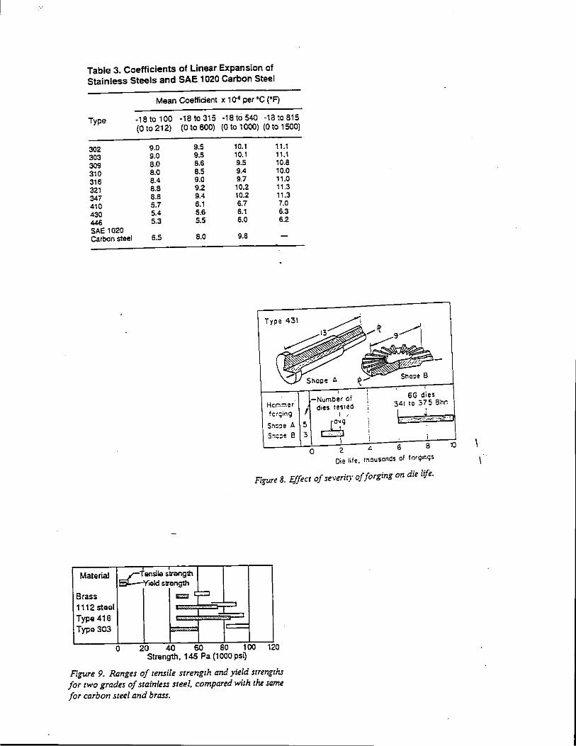
Table 3. Coefficients of Linear Expansion of Stainless Steels and SAE 1020 Carbon Steel
Mean Coefficient x 1 ~ per •c ('F)
Type ·18to100 ·18 to 315 -18tos40 ·18 to 815 (O to 212) (0 to 600) (0 to 1 000) (0 to 1 500)
302 9.0 9.5 10.1 11.1
303 9.0 9.5 10.1 11.1
309 8.0 8.6 9.5 10.8 310 8.0 8.5 9.4 10.0
316 8.4 9.0 9.7 11.0
321 8.8 9.2 10.2 11.3
347 8.8 9.4 10.2 11.3
410 5.7 6.1 6.7 7.0
430 5.4 5.6 6.1 6.3
446 5.3 5.5 6.0 6.2 SAE 1020 carbon steel 6.5 8.0 9.8
Type 431
6G dies 341 to 375 3M HeMmer
fc~;ing
-Number of f dies tesTed
I '
ro~g L .,...,.!~~·~
C:::J I
5:-::::::e 8 3
2 6 0 8
Die life, mouscnds of forg1ngs
Figure 8. Effect of severity of forging on die life.
Material ~ ensiMJ strength YM>Id strength
~ Brass vo;:J
1112steal ...... ..l Type 416 ····.·.···-·-· _ ....
Type 303 i= 0 20 40 60 80 100 120
Strength, 145 Pa (1 000 ps~
Figure 9. Ranges of rensile srrengrh and yield srrengrhs for rwo grades of srainless sreel. compared wirh rhe same for carbon sreel and brass.
10
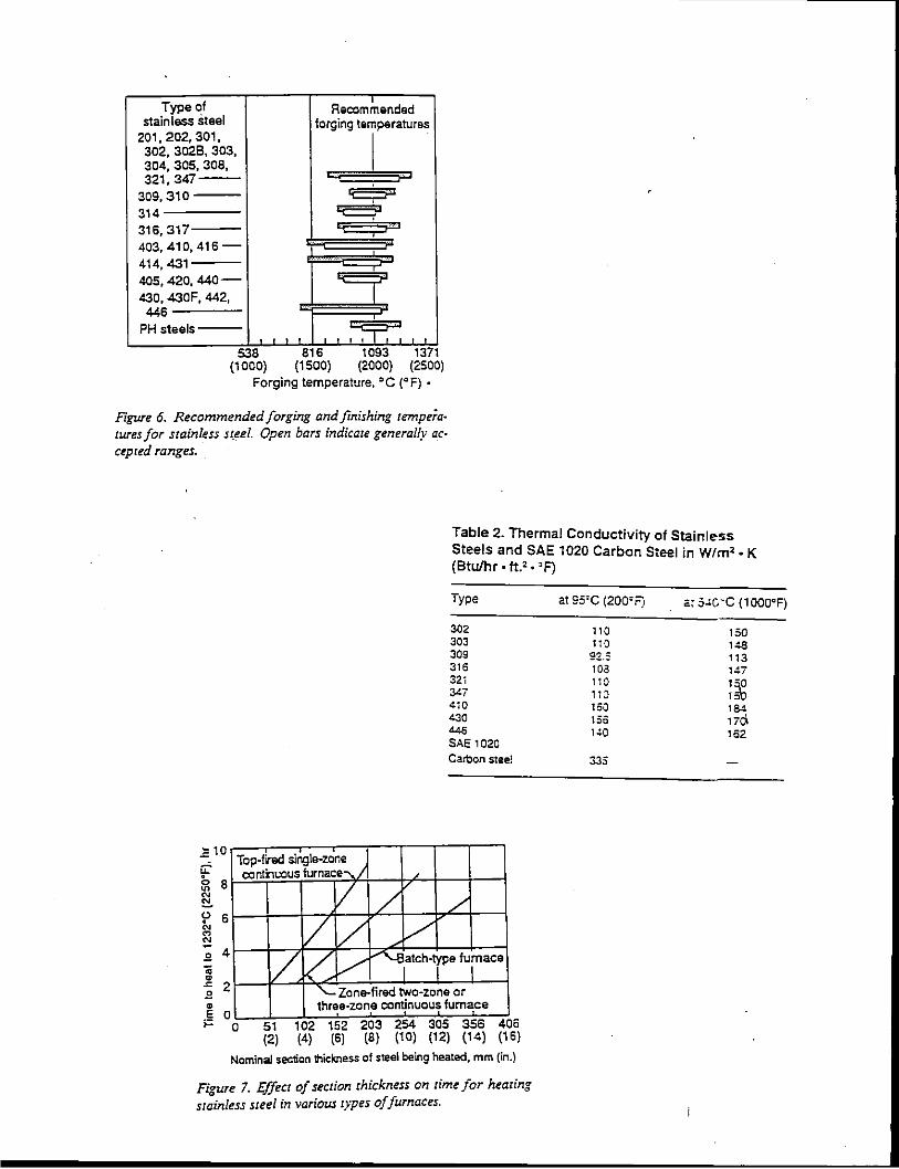
Type of Recom:nendad s1ainless steel forging te~peratures
201. 202, 301. 302, 3028, 303, 304, 305, 308, 321,347--
309,310 L:::;: 314 ~ 316, 317
. ' .
403,410,416-414, 431
~ 405, 420, 440-430, 430F, 442,
446 PH steels---
" :T. " ' 538 816 1093 1371
(1 000) (1 500) (2000) (2500) Forging temperature, 'C ('F) •
Figure 6. Recommended forging and finishing rempera· tures for stainless S(~el. Open bars indicace generally ac· cepced ranges.
Table 2. Thermal Conductivity of Stainless Steels and SAE 1020 Carbon Steel in Wlm'. K (Btulhr ·ft.'. 'F)
Type
302 303 309 316 32i 347 410 430 446 SAE 1020 Carbon stee!
Top-fired single-zone continuous furnace--. I
..c 10
I' 6 "' "' "' 3 4 ;; ~
-"' 2 3 ~
E 0 i= 0
/ / /
/ i/ /
/. / v ~atch-~pe fu\ace
'-Zone-fired two-zone or three· zone continuous furnace
51 102 152 203 254 305 356 406 (2) (4) (6) (8) (1 0) (1 2) (1 4) (1 6)
Nominal section thickness of steel being heated, mm (in.)
Figure 7. Effect of section thickness on rime for hearing srainles.s steel in various types of furnaces.
at 95'C (200'F) •: s~o··c (1000'F)
110 150 110 148
92.:: 113 103 147 110 1 ·o 110 1~ 150 1S4 130 17ci 10:.0 162
335
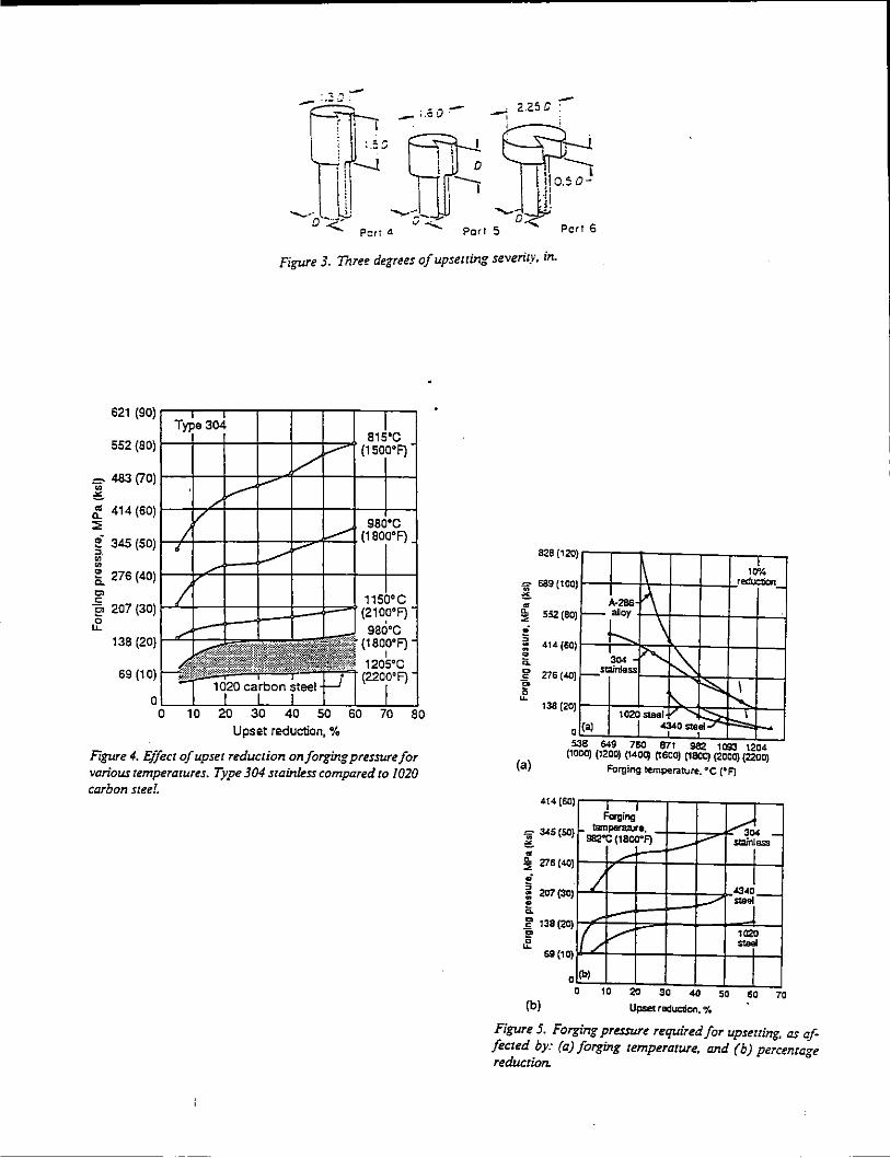
- :.3]~ _;.60~ -2.25C
l\\o-~ ~a~
Pori 5 Fieri 6
Figure 3. Three degrees of upsetting seven·ry. in.
69 (10)
0~~~~~~~~~~~~~ 80
Upset reduction,%
Figure 4. Effect of upset reduction on forging pressure for various temperatures. Type 304 stainless compared to 1020 carbon steel.
828 (120 )
) "';;; 689 {100 <!. ~
1\
A-286
'"' )-c \ ~ 552 (80
"= 414(50 ) 1304 ~~
) f--slainless -.....: • a ~ 276 (40 r ~
138 (20 ) 10j Sleel ::---....
(a) -o:r'O Sleel-' 0
1Jt, red!.aion_
~ \
(a)
538 &49 760 871 982 1093 1204 {1000) (1200) ~400) ~600) ~800) {2000) {2200)
Forging temperature. •c (•F)
414(60 ) ~ctg;ng' ----d_ '=iii 345 (50
<!. )"-"'""""""'·· 982"C (1800"F) _,... 'i ... ~
~ Z7Ei (40)
§. 207 (30)
a ~ 138(20)
" of
(b)
69(10)
0
_..
/ 434J ./ 1-
(/ / 11l20 ,.., (b) I
0 10 20 30 40 so so 70
Upset raduc:rion. %
Figure 5. Forging pressure required for upseuing, as affected by: (a) forging temperature, and (b) percentage reduction.
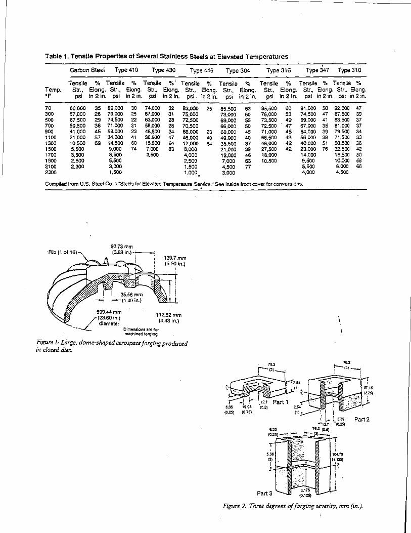
Table 1. Tensile Properties of Several Stainless Steels at Elevated Temperatures
Carbon Steel Type 4t0 Type 430 Type446 Type 304 Type 316 Type 347 Type 310
Tensile % Tensile % Tensile %·. Tensile % Tensile % Tensile % Tensile % Tensile % Temp. Str., Elan g. Str., Elong. Str., Elong, Str .. Elong. Str., Elong. Str., Elong. Str., E!ong. Str .. Elong. 'F psi in 2in. psi in 2 in. psi in 2 in. psi in 2 in. psi in 2 in. psi in 2 in. psi in 2 in. psi in2 in.
70 60.000 35 89.000 30 74.000 32 83,000 25 85,500 63 85.500 60 91.000 50 92.000 47 300 67,000 28 79.000 25 67,000 31 75,000 73,000 60 76,000 53 74.500 <7 87,500 39 500 67.500 29 74,500 22 63,000 28 72,500 69,000 55 73.500 49 69,000 41 83,500 37 700 59,500 36 71.000 21 58,000 28 70,500 66,000 so 72.500 47 67.000 35 61.000 37 900 41,000 45 58.000 23 48,500 34 66,000 23 60,000 45 71,000 45 64.000 39 79.500 34 1100 21,000 57 34,000 41 30.500 47 46,000 40 49,000 40 66,500 43 56.000 39 71,500 33 1300 10,500 69 14,500 60 15.500 64 17,000 84 35.500 37 46.000 42 40.000 51 50.500 36 1500 s.soo 9,000 74 7,000 83 8,000 21,000 39 27,500 42 23.000 76 32,500 42 1700 3,500 8,500 3,500 4,000 12.000 46 18.000 14.000 18.500 50 1900 2,600 5,500 2,500 7,000 63 10,500 9,500 10.000 sa 2100 2,300 3,000 1,500 4,500 n 5,500 6.000 66 2300 1,500 1,000. 3,000 4,000 4.500
Compiled from U.S. Steel Co.'s •steels for Elevated Temperature Seryice.~ See inside front cover for conversions.
Rib (1 of 16) 93.73 mm (3.69 in.)·7---'
139.7mm (5.50 in.)
112.52 mm (4.43 in.)
Dimensions are 1or machined forging
Figure r I..tirge, dome-shaped aerospace forging produced in closed dies.
\
Figure 2. Three degrees of foiging severity, mm (in.).
Related Documents