Since 1985 V07 The World’s Best Locking Fastener Installation Instructions ~~~~~~~~~~~~~~~~~~~~ Railroad Roller Bearing Cap Screw Locking System

Welcome message from author
This document is posted to help you gain knowledge. Please leave a comment to let me know what you think about it! Share it to your friends and learn new things together.
Transcript

Since 1985
V07
The World’s Best Locking Fastener
Installation Instructions~~~~~~~~~~~~~~~~~~~~
Railroad Roller Bearing Cap Screw Locking System
Description
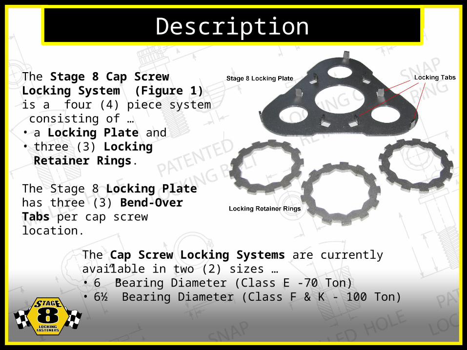
The Stage 8 Cap Screw Locking System (Figure 1) is a four (4) piece system consisting of …• a Locking Plate and • three (3) Locking Retainer Rings.
The Stage 8 Locking Plate has three (3) Bend-Over Tabs per cap screw location.
The Cap Screw Locking Systems are currently available in two (2) sizes …• 6” Bearing Diameter (Class E -70 Ton)• 6½” Bearing Diameter (Class F & K - 100 Ton)
1. Install the Locking Plate
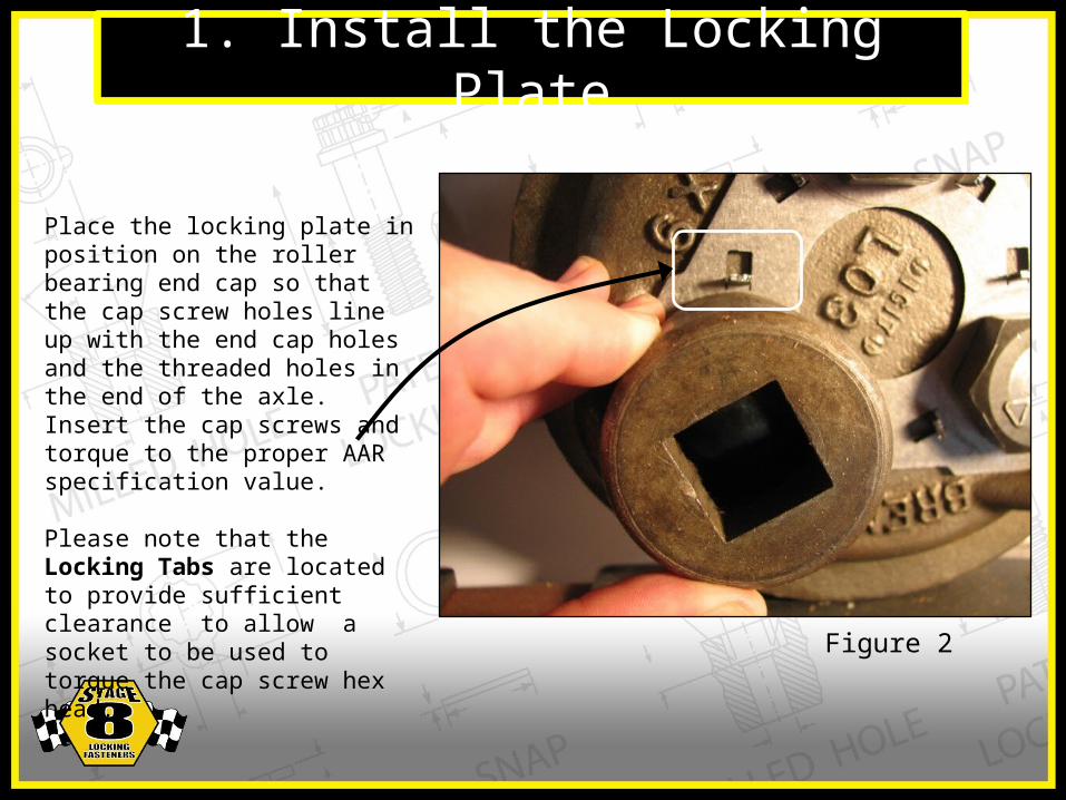
Place the locking plate in position on the roller bearing end cap so that the cap screw holes line up with the end cap holes and the threaded holes in the end of the axle. Insert the cap screws and torque to the proper AAR specification value.
Please note that the Locking Tabs are located to provide sufficient clearance to allow a socket to be used to torque the cap screw hex head.
Figure 2

2. Position the Locking Retainer Ring
The objective is to place the Locking Retainer Ring in position so that the three (3) Locking Tabs can be bent into the notches of the Locking Retainer Ring and lock the cap screw in place.
Figure 3 indicates a Locking Retainer Ring where the Notch is in alignment with the Locking Tabs. If alignmentis achieved in the first attempt, proceed to Step 3.
Figure 3
NOTCH
LOCKINGTAB
2. Position the Locking Retainer Ring (cont’d)
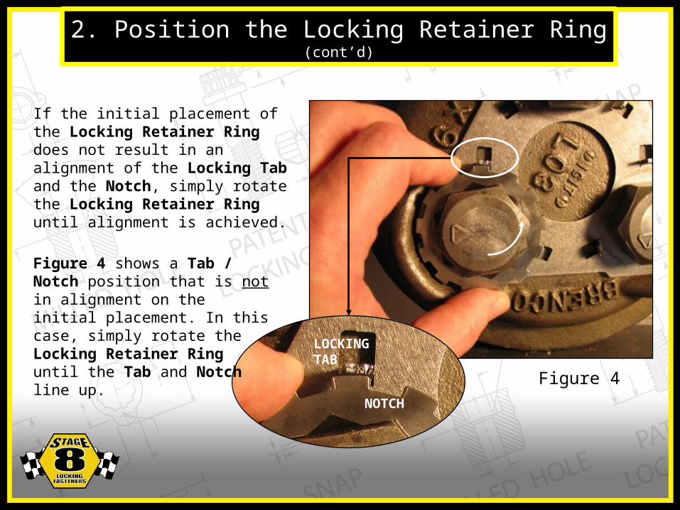
If the initial placement of the Locking Retainer Ring does not result in an alignment of the Locking Tab and the Notch, simply rotate the Locking Retainer Ring until alignment is achieved.
NOTCH
LOCKINGTAB
Figure 4 shows a Tab / Notch position that is not in alignment on the initial placement. In this case, simply rotate the Locking Retainer Ring until the Tab and Notch line up.
Figure 4

3. Lock the Cap ScrewOnce the Locking Tabs are aligned with the Notches, simply bend the tabs over using a screwdriver or chisel and hammer.
The Locking Tabs do not have to be hammered flat onto the surface of the Locking Retainer Ring. A 45° bend angle is sufficient to hold the Locking Retainer Ring in place.
Figure 6 depicts a properly installed locking system, which will provide over 10 times the torque resistance to loosening compared to the standard locking plate.
Figure 5
Figure 6
Related Documents


![admin.bdi-usa.comadmin.bdi-usa.com/FileUploads/CMSFiles/ProductGuide[0].pdf · LOCKING INDUSTRIAL ADHESIVES AND SEALANTS . ... Taper Roller Thrust Z-Mill TIMKEN ... Lovejoy Magnadrive](https://static.cupdf.com/doc/110x72/5ab0ed817f8b9a1d168bf2c3/adminbdi-usa-0pdflocking-industrial-adhesives-and-sealants-taper-roller.jpg)