STAF, STAF-SG BALANCING BALANCING VALVES BALANCING VALVE – PN 16 AND PN 25 – DN 20-400 A flanged, cast iron (STAF) and ductile iron (STAF-SG) balancing valve that delivers accurate hydronic performance in an impressive range of applications. The STAF/STAF-SG is ideal for use mainly on the secondary side in heating and cooling systems. HANDWHEEL Equipped with a digital read-out, the handwheel ensures accurate and straightforward balancing. SELF-SEALING MEASURING POINTS For simple, accurate balancing. POSITIVE SHUT-OFF FUNCTION For easy maintenance.

Welcome message from author
This document is posted to help you gain knowledge. Please leave a comment to let me know what you think about it! Share it to your friends and learn new things together.
Transcript
STAF, STAF-SG BALANCING
BALANCING VALVES
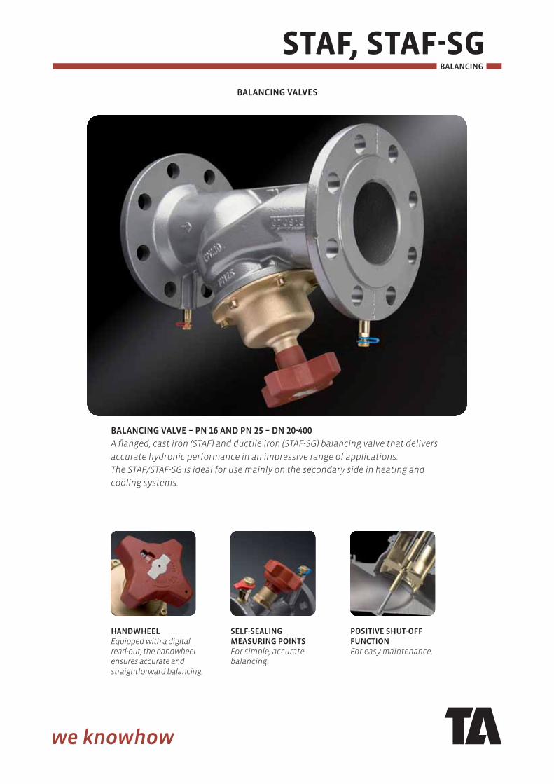
BALANCING VALVE – PN 16 AND PN 25 – DN 20-400
A fl anged, cast iron (STAF) and ductile iron (STAF-SG) balancing valve that delivers
accurate hydronic performance in an impressive range of applications.
The STAF/STAF-SG is ideal for use mainly on the secondary side in heating and
cooling systems.
HANDWHEELEquipped with a digital read-out, the handwheel ensures accurate and straightforward balancing.
SELF-SEALING MEASURING POINTSFor simple, accurate balancing.
POSITIVE SHUT-OFF FUNCTIONFor easy maintenance.
STAF, STAF-SG BALANCING
2
TECHNICAL DESCRIPTION
Applications:Heating and cooling systems
Functions:BalancingPre-settingMeasuring Shut-off (The balancing cone for valve DN 65-400 is pressure released).
Dimensions:STAF: DN 65-150STAF-SG: DN 20-400
Pressure class:STAF: PN 16STAF-SG: PN 16 and PN 25 (see each product)
Temperature:Max. working temperature: 120°CFor higher temperatures (max. 150°C), please contact the nearest sales offi ce.Min. working temperature: STAF: -10°CSTAF-SG: -20°C
Material:Body, STAF: Cast iron EN-GJL-250 (GG 25). Body, STAF-SG: Ductile iron EN-GJS-400-15. DN 20-150: Bonnet, restriction cone and spindle of AMETAL®.DN 200-300: Bonnet of ductile iron, cone of Bronze and spindle of AMETAL®. DN 350-400: Bonnet of ductile iron, cone of silicon brass CuZn16Si4-C (EN 1982) or brass CuZn35Pb2Al-C-GS (EN 1982) and spindle of AMETAL®. Seat seal: Cone with EPDM ring. Bonnet bolts: Chromed steel. Handwheel: DN 20-150 polyamide, DN 200-400 aluminium. AMETAL® is the dezincifi cation resistant alloy of TA.
Surface treatment:DN 20-200: Epoxy painting. DN 250-400: Duasolid painting.
Marking:Body: TA, PN, DN, fl ow direction arrow, material and casting date (year, month, day).CE-marking according to table:
Marking STAF STAF-SG
(PN 16)
STAF-SG
(PN 25)
CE DN 65-150 DN 200 DN 50-125CE 0409* DN 250-400 DN 150-400
*) Notifi ed body.
Face to face length:ISO 5752 series 1, BS 2080 and EN 558-1 series 1.
STAF, STAF-SG
3
BALANCING
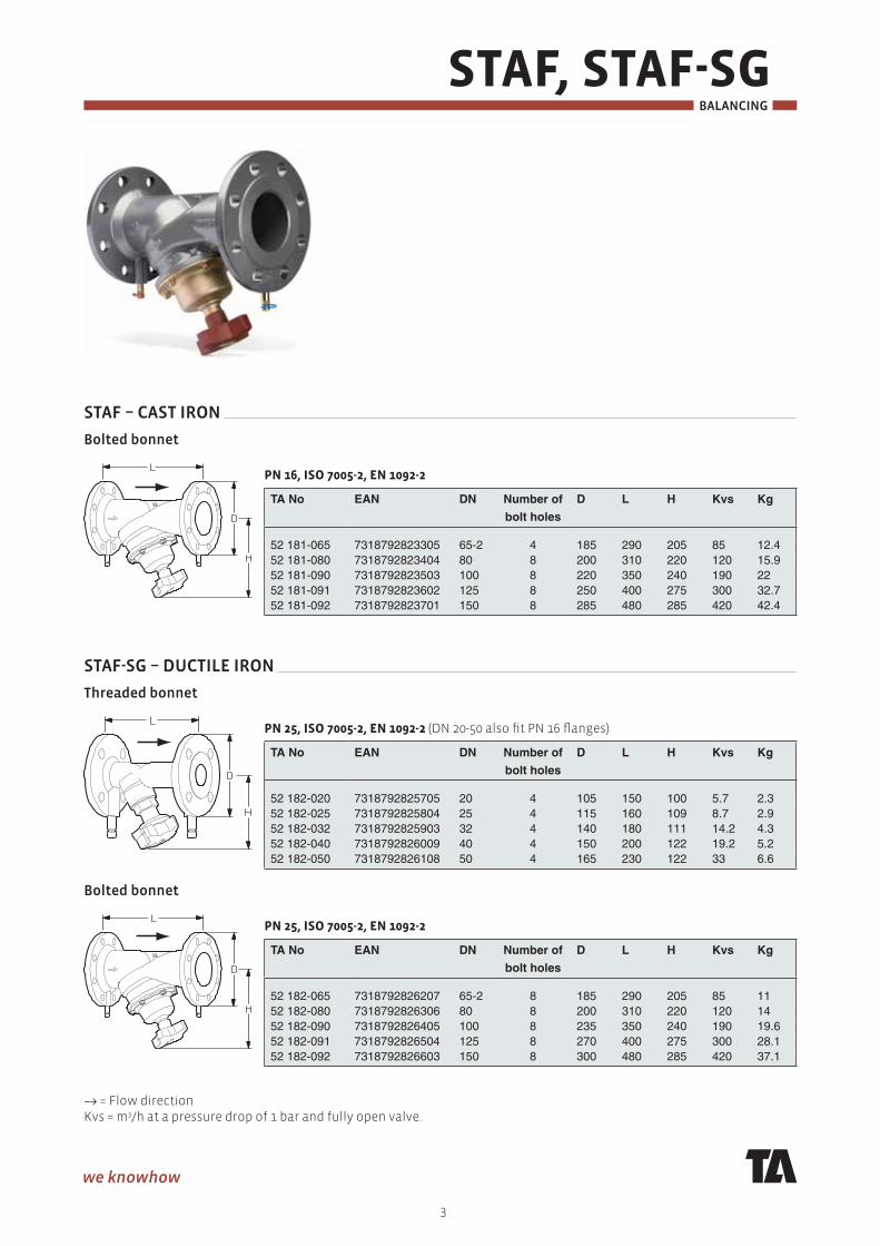
STAF – CAST IRON
Bolted bonnet
PN 16, ISO 7005-2, EN 1092-2
TA No EAN DN Number of
bolt holes
D L H Kvs Kg
52 181-065 7318792823305 65-2 4 185 290 205 85 12.452 181-080 7318792823404 80 8 200 310 220 120 15.952 181-090 7318792823503 100 8 220 350 240 190 2252 181-091 7318792823602 125 8 250 400 275 300 32.752 181-092 7318792823701 150 8 285 480 285 420 42.4
STAF-SG – DUCTILE IRON
Threaded bonnet
PN 25, ISO 7005-2, EN 1092-2 (DN 20-50 also fi t PN 16 fl anges)
TA No EAN DN Number of
bolt holes
D L H Kvs Kg
52 182-020 7318792825705 20 4 105 150 100 5.7 2.352 182-025 7318792825804 25 4 115 160 109 8.7 2.952 182-032 7318792825903 32 4 140 180 111 14.2 4.352 182-040 7318792826009 40 4 150 200 122 19.2 5.252 182-050 7318792826108 50 4 165 230 122 33 6.6
Bolted bonnet
PN 25, ISO 7005-2, EN 1092-2
TA No EAN DN Number of
bolt holes
D L H Kvs Kg
52 182-065 7318792826207 65-2 8 185 290 205 85 1152 182-080 7318792826306 80 8 200 310 220 120 1452 182-090 7318792826405 100 8 235 350 240 190 19.652 182-091 7318792826504 125 8 270 400 275 300 28.152 182-092 7318792826603 150 8 300 480 285 420 37.1
→ = Flow directionKvs = m3/h at a pressure drop of 1 bar and fully open valve.
STAF, STAF-SG BALANCING
4
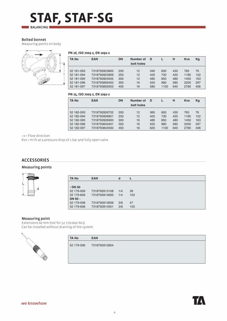
Bolted bonnetMeasuring points on body
PN 16, ISO 7005-2, EN 1092-2
TA No EAN DN Number of
bolt holes
D L H Kvs Kg
52 181-093 7318792823800 200 12 340 600 430 765 7652 181-094 7318792823909 250 12 425 730 420 1185 12252 181-095 7318792824005 300 12 485 850 480 1450 16352 181-096 7318793859402 350 16 520 980 585 2200 29752 181-097 7318793859303 400 16 580 1100 640 2780 406
PN 25, ISO 7005-2, EN 1092-2
TA No EAN DN Number of
bolt holes
D L H Kvs Kg
52 182-093 7318792826702 200 12 360 600 430 765 7652 182-094 7318792826801 250 12 425 730 420 1185 12252 182-095 7318792826900 300 16 485 850 480 1450 16352 182-096 7318793843401 350 16 555 980 585 2200 29752 182-097 7318793843500 400 16 620 1100 640 2780 406
→ = Flow directionKvs = m3/h at a pressure drop of 1 bar and fully open valve.
ACCESSORIES
Measuring points
TA No EAN d L
- DN 50 52 179-009 7318792813108 1/4 3952 179-609 7318792814600 1/4 103DN 65 - 52 179-008 7318792813009 3/8 4752 179-608 7318792814501 3/8 103
Measuring pointExtensions 60 mm (not for 52 179-000/-601).Can be installed without draining of the system.
TA No EAN
52 179-006 7318792812804
L
d
STAF, STAF-SG
5
BALANCING
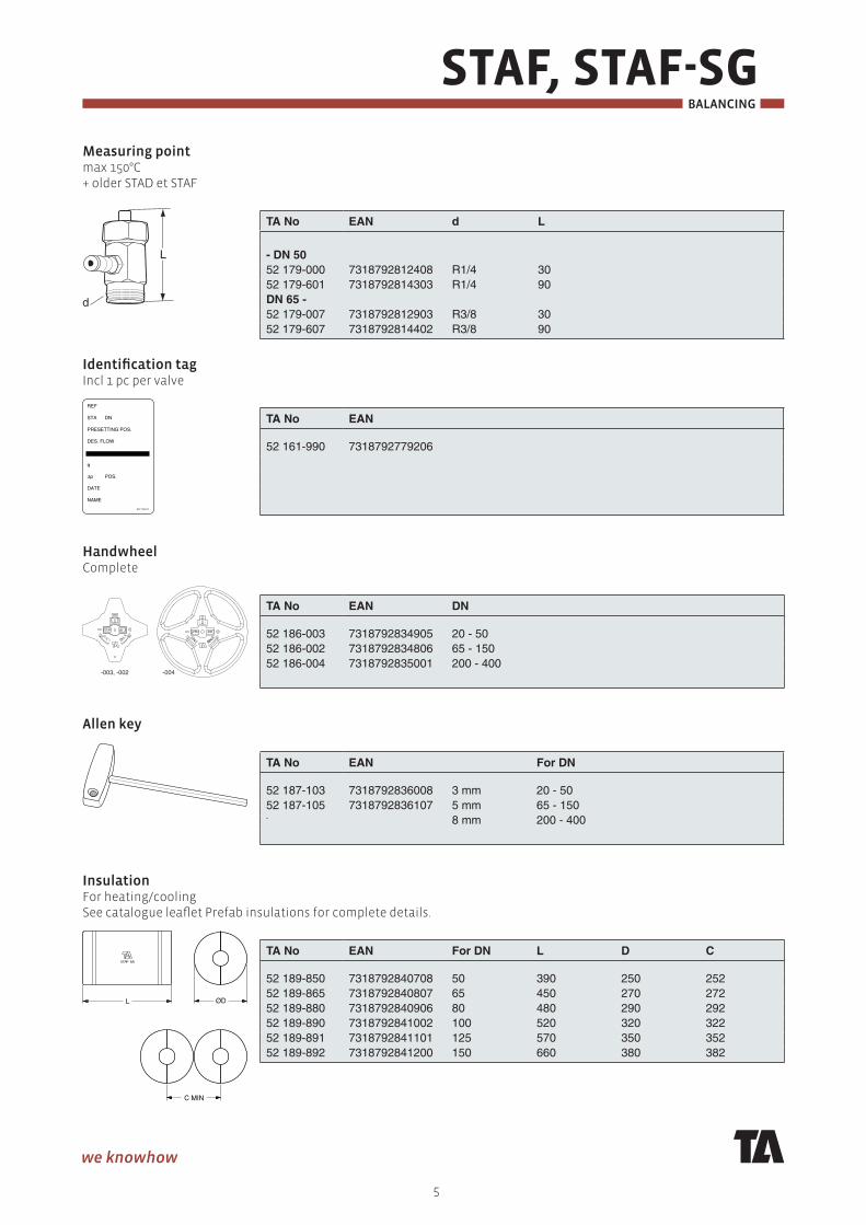
Measuring pointmax 150°C+ older STAD et STAF
TA No EAN d L
- DN 50 52 179-000 7318792812408 R1/4 3052 179-601 7318792814303 R1/4 90DN 65 - 52 179-007 7318792812903 R3/8 3052 179-607 7318792814402 R3/8 90
Identifi cation tagIncl 1 pc per valve
TA No EAN
52 161-990 7318792779206
HandwheelComplete
TA No EAN DN
52 186-003 7318792834905 20 - 5052 186-002 7318792834806 65 - 15052 186-004 7318792835001 200 - 400
Allen key
TA No EAN For DN
52 187-103 7318792836008 3 mm 20 - 5052 187-105 7318792836107 5 mm 65 - 150- 8 mm 200 - 400
InsulationFor heating/coolingSee catalogue leafl et Prefab insulations for complete details.
TA No EAN For DN L D C
52 189-850 7318792840708 50 390 250 25252 189-865 7318792840807 65 450 270 27252 189-880 7318792840906 80 480 290 29252 189-890 7318792841002 100 520 320 32252 189-891 7318792841101 125 570 350 35252 189-892 7318792841200 150 660 380 382
d
L
-003, -002 -004
STAF, STAF-SG BALANCING
6
MEASURING POINTS
Measuring points are self-sealed. Remove the cap and insert the probe through the seal.
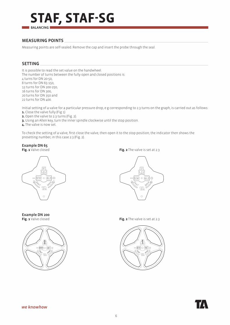
SETTING
It is possible to read the set value on the handwheel. The number of turns between the fully open and closed positions is:4 turns for DN 20-50,8 turns for DN 65-150,12 turns for DN 200-250,16 turns for DN 300,20 turns for DN 350 and22 turns for DN 400. Initial setting of a valve for a particular pressure drop, e g corresponding to 2.3 turns on the graph, is carried out as follows:1. Close the valve fully (Fig 1)2. Open the valve to 2.3 turns (Fig. 2).3. Using an Allen key, turn the inner spindle clockwise until the stop position.4. The valve is now set. To check the setting of a valve, fi rst close the valve, then open it to the stop position; the indicator then shows the presetting number, in this case 2.3 (Fig. 2).
Example DN 65Fig. 1 Valve closed Fig. 2 The valve is set at 2.3
Example DN 200Fig. 1 Valve closed Fig. 2 The valve is set at 2.3
STAF, STAF-SG
7
BALANCING
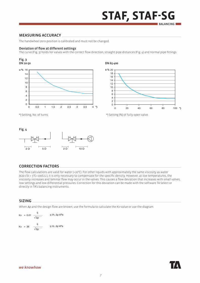
MEASURING ACCURACY
The handwheel zero position is calibrated and must not be changed.
Deviation of fl ow at different settingsThe curve (Fig. 3) holds for valves with the correct fl ow direction, straight pipe distances (Fig. 4) and normal pipe fi ttings.
Fig. 3DN 20-50 DN 65-400
*) Setting, No. of turns. *) Setting (%) of fully open valve.
Fig. 4
2 D 10 D2 D5 D
CORRECTION FACTORS
The fl ow calculations are valid for water (+20°C). For other liquids with approximately the same viscosity as water (≤20 cSt = 3°E=100S.U.), it is only necessary to compensate for the specifi c density. However, at low temperatures, the viscosity increases and laminar fl ow may occur in the valves. This causes a fl ow deviation that increases with small valves, low settings and low differential pressures. Correction for this deviation can be made with the software TA Select or directly in TA’s balancing instruments.
SIZING
When Δp and the design fl ow are known, use the formula to calculate the Kv-value or use the diagram.
0
2
4
6
8
10
12
14
16
0 0,5 1 1,5 2 2,5 3 3,5 4 *)
± %
0 2 4 6 8
10 12 14 16 18 20
0 20 40 60 80 100 *)
± %
STAF, STAF-SG BALANCING
8
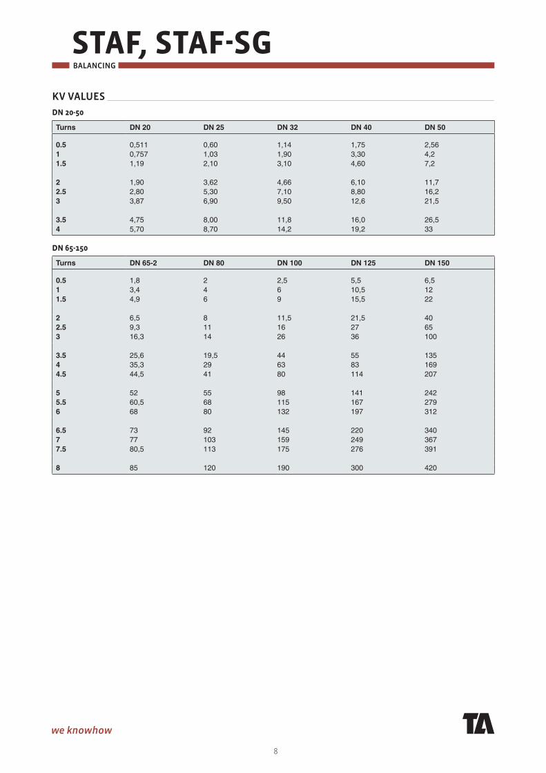
KV VALUES
DN 20-50
Turns DN 20 DN 25 DN 32 DN 40 DN 50
0.5 0,511 0,60 1,14 1,75 2,561 0,757 1,03 1,90 3,30 4,21.5 1,19 2,10 3,10 4,60 7,2 2 1,90 3,62 4,66 6,10 11,72.5 2,80 5,30 7,10 8,80 16,23 3,87 6,90 9,50 12,6 21,5 3.5 4,75 8,00 11,8 16,0 26,54 5,70 8,70 14,2 19,2 33
DN 65-150
Turns DN 65-2 DN 80 DN 100 DN 125 DN 150
0.5 1,8 2 2,5 5,5 6,51 3,4 4 6 10,5 121.5 4,9 6 9 15,5 22 2 6,5 8 11,5 21,5 402.5 9,3 11 16 27 653 16,3 14 26 36 100 3.5 25,6 19,5 44 55 1354 35,3 29 63 83 1694.5 44,5 41 80 114 207 5 52 55 98 141 2425.5 60,5 68 115 167 2796 68 80 132 197 312 6.5 73 92 145 220 3407 77 103 159 249 3677.5 80,5 113 175 276 391 8 85 120 190 300 420
STAF, STAF-SG
9
BALANCING
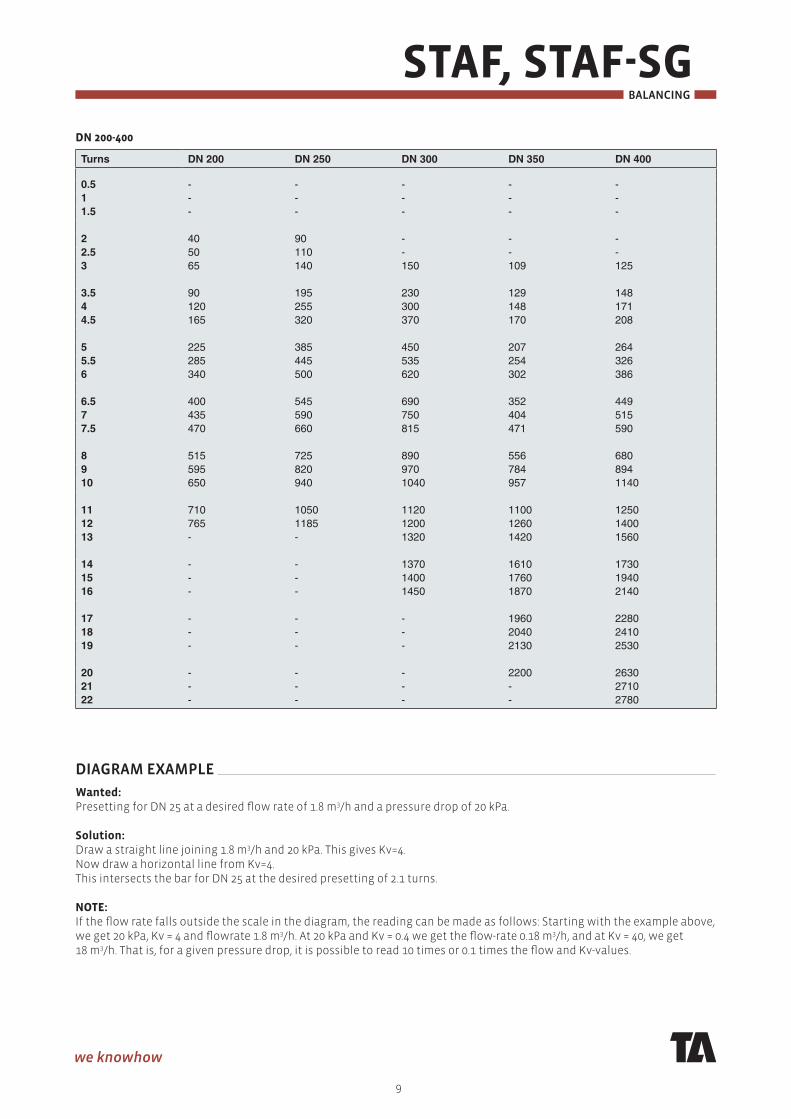
DN 200-400
Turns DN 200 DN 250 DN 300 DN 350 DN 400
0.5 - - - - -1 - - - - -1.5 - - - - - 2 40 90 - - -2.5 50 110 - - -3 65 140 150 109 125 3.5 90 195 230 129 1484 120 255 300 148 1714.5 165 320 370 170 208 5 225 385 450 207 2645.5 285 445 535 254 3266 340 500 620 302 386 6.5 400 545 690 352 4497 435 590 750 404 5157.5 470 660 815 471 590 8 515 725 890 556 6809 595 820 970 784 89410 650 940 1040 957 1140 11 710 1050 1120 1100 125012 765 1185 1200 1260 140013 - - 1320 1420 1560 14 - - 1370 1610 173015 - - 1400 1760 194016 - - 1450 1870 2140 17 - - - 1960 228018 - - - 2040 241019 - - - 2130 2530 20 - - - 2200 263021 - - - - 271022 - - - - 2780
DIAGRAM EXAMPLE
Wanted:Presetting for DN 25 at a desired fl ow rate of 1.8 m3/h and a pressure drop of 20 kPa.
Solution:Draw a straight line joining 1.8 m3/h and 20 kPa. This gives Kv=4. Now draw a horizontal line from Kv=4. This intersects the bar for DN 25 at the desired presetting of 2.1 turns.
NOTE:If the fl ow rate falls outside the scale in the diagram, the reading can be made as follows: Starting with the example above, we get 20 kPa, Kv = 4 and fl owrate 1.8 m3/h. At 20 kPa and Kv = 0.4 we get the fl ow-rate 0.18 m3/h, and at Kv = 40, we get 18 m3/h. That is, for a given pressure drop, it is possible to read 10 times or 0.1 times the fl ow and Kv-values.
STAF, STAF-SG BALANCING
10
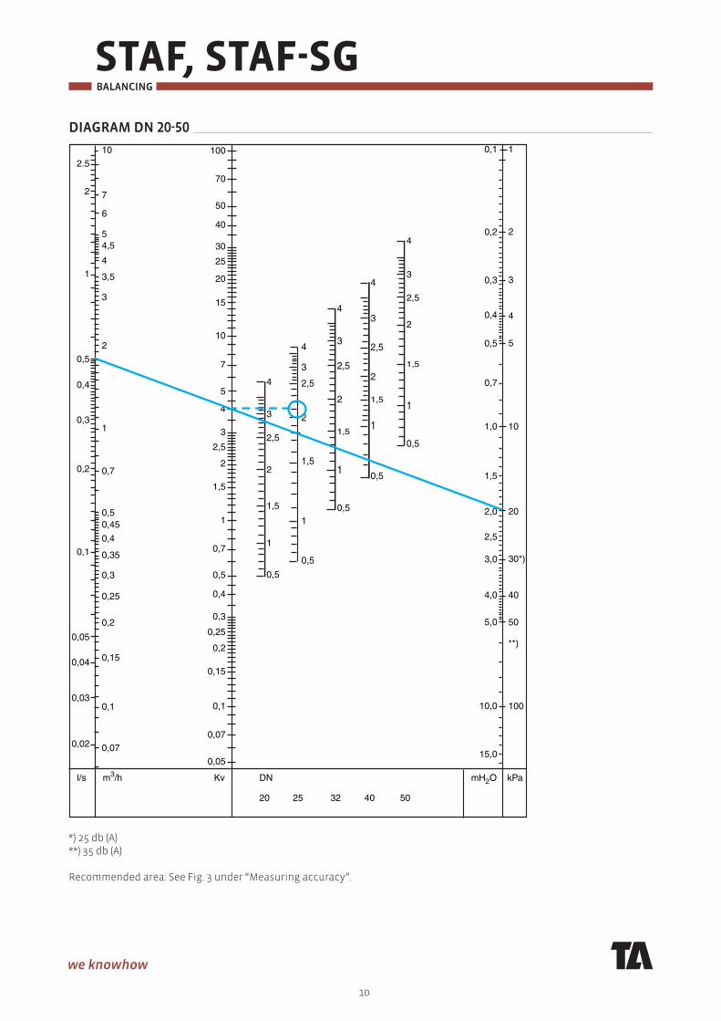
DIAGRAM DN 20-50
15,00,05
0,07
0,1
0,15
0,2
0,25
0,3
0,4
0,5
0,7
1
1,5
2
2,5
3
4
5
7
10
15
20
25
30
40
50
2
1
0,5
0,4
0,3
0,2
0,1
0,05
0,04
0,03
0,02
2.5
10
7
6
54,5
4
3,5
3
2
1
0,7
0,50,45
0,4
0,35
0,3
0,25
0,2
0,15
0,1
0,07
l/s m3/h mH2O kPaKv DN
20 25 32 40 50
70
100
10,0
5,0
4,0
3,0
2,5
2,0
1,5
1,0
0,7
0,5
0,4
0,3
0,2
0,1 1
2
3
4
5
4
3
2,5
2
1,5
1
0,5
20
10
30*)
40
50
100
**)
4
3
2,5
2
1,5
1
0,5
4
3
2,5
2
1,5
1
0,5
4
3
2,5
2
1,5
1
0,5
4
3
2,5
2
1,5
1
0,5
*) 25 db (A)**) 35 db (A) Recommended area: See Fig. 3 under “Measuring accuracy”.

STAF, STAF-SG
11
BALANCING
DIAGRAM DN 65-150
1
1,5
2
2,5
3
4
5
7
10
15
20
25
30
40
50
70
100
150
200
250
300
400
500
20
10
5
4
3
2
1
0,5
0,4
0,3
27,8 100
70
60
5045
40
35
30
20
10
15
7
54,5
4
3,5
3
2,5
2
1,5
1
l/s m3/h mH2O kPaKv DN 65-2 80 100 125 150
700
1000
10,0
5,0
4,0
3,0
2,5
2,0
1,5
1,0
0,7
0,5
0,4
0,3
0,2
0,1 1
2
3
4
5
4
5
678
3
2
1
0,5
20
30*)
40
50
100
**)
4
5
6
78
3
2
1
0,5
4
5
6
78
3
2
1
0,5
4
5
6
78
3
2
1
0,5
4
5
678
3
2
1
*) 25 db (A)**) 35 db (A) Recommended area: See Fig. 3 under “Measuring accuracy”.
STAF, STAF-SG BALANCING
12
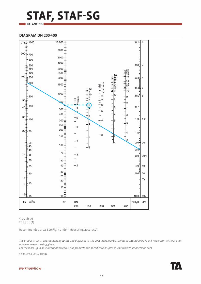
DIAGRAM DN 200-400
10
15
20
25
30
40
50
70
100
150
200
250
300
400
500
700
1000
1500
2000
2500
3000
4000
5000
200
100
50
40
30
20
10
5
4
3
278 1000
700
600
500450
400
350
300
200
100
150
70
5045
40
35
30
25
20
15
10
l/s m3/h mH2O kPaKv DN
200 250 300
7000
10 000
10,0
5,0
4,0
3,0
2,5
2,0
1,5
1,0
0,7
0,5
0,4
0,3
0,2
0,1 1
2
3
4
5
4
3
6
5
7
89101112
2
20
1 0
30*)
40
50
100
**)
4
3
6
5
7
89101112
2
4
3
6
5
7
8
10121416
350 400
6
5
8
7
9
10111213
16
4
3
6
5
7
8
10
12
14
16
3
4
14
2018
9
11
13
182022
*) 25 db (A)**) 35 db (A) Recommended area: See Fig. 3 under “Measuring accuracy”.
The products, texts, photographs, graphics and diagrams in this document may be subject to alteration by Tour & Andersson without prior
notice or reasons being given.
For the most up to date information about our products and specifi cations, please visit www.tourandersson.com.
5-5-15 STAF, STAF-SG 2009.11
Related Documents