STADIUM & SPORT HALL

Welcome message from author
This document is posted to help you gain knowledge. Please leave a comment to let me know what you think about it! Share it to your friends and learn new things together.
Transcript

STADIUM & SPORT HALL

www.seatupturkey.com.tr

STADIUM SERIES
WELLCOME TO OUR STADIUM SERIES
In our factory we have our own plastic injection
machine to produce stadium plastic chairs.
As well SeatUpTurkey® has much more to offer
you: We develop VIP Seats for Stadium and sport
salons and these models are serving Important
and fancy sports clubs in Turkey and around the
world.
As well recently we became a main role in
Turkey and in the middle east for the production
of telescopic seating systems and portable
seating system.
Thanks to the metal section in our factory which
has been extended for that purpose.has been
extended for that purpose.

STADIUS 220 General Features
• Producing according to ISO 9001:2008 management system.
•Ourproductsstandsthestandardsof:V2-UL94(Flammability),
ISO4892-2(Ultraviolet) and TSEN12727 (Unbreakable).
• All the metal parts that are in use in our products are: TS EN 10204
3 / 1 standard.
• We only use original raw materials during the producing process.
• In order to provide maximum protection from sun light in outdoor
and lights in indoor we use: Ultraviolet stabilizer.
• WeonlyusehighqualitycolorsinordertoavoidfadingofColorsasresult
Ofexposuretosunlightorotherlights.
• Thestructureofthebackandtheseatofourseatsisbuiltasorthopaedic
Inordertoavoiduncomfortablefeelingwhilesittingforlongtime.
• As a result of using original raw materials with high quality our
stadium seats always looks shiny and have live color.
• Our stadium chairs have 4 mounting points and for each point
there is hard plastic cover for protection and for esthetic.
• In the center of our stadium chairs there is a canal that will collect
out water in a case of rain or humidity and therefore the chair will
stay dry rather if it's located in indoor or outdoor area.
STADIUM SERIES STADIUM SERIES
6 | STADIUM SERIES | 7

STADIUM SERIES STADIUM SERIES
8 | STADIUM SERIES | 9

STADIUS 111
STADIUM SERIES STADIUM SERIES
10 | STADIUM SERIES | 11

STADIUS TIP-UP 401 General Features
• The stadium seats will be produce by polythene or polypropylene materiels which have high-strenght
values.
• In raw material doesn't have non-standard (scrap) and weighting material filler.
• UV stabilizer for protective purposes and paint to prevent discoloration to be added in the raw
meterials which will be used to production folding stadium seat on request.
• Maximum-resistant paint is used to against the light.
• Production is carried out according to ISO 9001:2008 quality management system.
• Due to the use of the original raw materials, our stadium seat colors are bright and vivid.
• 4 Point made easy mounting provides the necessary rigidity.
• With the metal washers on the mounting points and relaxation resistance to breakage is increased
STADIUS 401
• Certainly not on the water bar.
• On the seat through the discharge channel, the water would drain at the bottom rung of chairs.
• Back and legs that will not disturb the structure and orthopedic seating is capable of.
• In line with customer demand; Ultraviolet Stabilizers spiked, fire retardant additive, light of sensitivity,
impact resistance against high product can be produced.
Note: The STADIUS 401 model can be produce with many versions and with combination between the
versions such as : -with upholstery, -with armreast, -with writing table, with fixing legs to the floor, with
fixed method to floor, and more.
STADIUM SERIES STADIUM SERIES
12 | STADIUM SERIES | 13

STADIUS TIP-UP 401 STADIUS TIP-UP 401
STADIUM SERIES STADIUM SERIES
14 | STADIUM SERIES | 15

STADIUS 401 with upholstery STADIUS 401 with armrest and table
STADIUM SERIES STADIUM SERIES
16 | STADIUM SERIES | 17

VIP SEATUP2 ANTI PANIC • Product has certified according to TS EN 12727.
• Seatrest and backrest frame are steel construction and are covered
by foam at the density
of 50±5 (kg/m³) in special aluminium moulds.
• Framed seatrest and backrest foam surfaces are upholstered with
desired fabric, leather or
articifial leather.
• Armrest structure is manufactured by aluminium, armrest is
manufactured by ABS plastic material.
• Armrests have antipanic feature. When user stands up from sitting
position, backrest and armrest
are closed together.
• When armchair is closed, it occupies as armrest carcass width and
leaves a wide usage area
for user at the passing area.
• Product is covered by nylon and packed into cartoon box.
Note: This model can be produce with many versions such as : - fixing
to stairs, fixing to floor with 2 legs and for Telescopic systemes.
STADIUM SERIES STADIUM SERIES
18 | STADIUM SERIES | 19

PLAYER SEAT
We are producing varieties of
player seats including the bench
and the Shelter construction
with unbreakable and Anti
UV fiber glass roof.
Models can be custom made.
STADIUM SERIES STADIUM SERIES
20 | STADIUM SERIES | 21

BLOW MOLDING SEATSFor stronger and extra durability performance we present our new Blow Molding Stadium Seats.
STADIUM SERIES STADIUM SERIES
22 | STADIUM SERIES | 23

TELESCOPIC SYSTEM
WELLCOME TO OUR TELESCOPIC SYSTEM
www.seatuptelescopic.com

TELESCOPIC SYSTEMS
The purpose of this technical specification; Telescopic Grandstand will be used for the manufacture of
all kinds of devices, equipment and grandstands national and / or international standards to ensure
the safety of life and property in accordance with the principles of determining the arrangements to
be made. According to the static calculations and architectural design of the project which will be the
statistical value of the steel material to be used in the system in the(TSE EN 10219-2) standard; steel
material is used. Lightweight Galvanized, specially formatted perforated U-profile are the main carri-
er of the profile systems with ST37 boxes manufactured, all along has been developed together with
coarse and fine products.
TELESCOPIC GRANDSTAND FEATURES
Telescopic grandstands total 3 and Platform 4 will consist of ordinary. Width for Platforms starting
from the Ground will be 80 cm, Width only for the bottom Platform will be 125 cm. When the Telescopic
Grandstands are open it will be 285 cm. When the Telescopic Grandstand closes, the Platforms will hide
into the last Platform and will cover 100 cm space.
PLATFORM AND CARRIER FRAME FEATURES
Skeleton of the platform in the manufacturing of 2 mm galvanized sheet metal bent in special forms and
sizes ISO 1461/1999 (E), DIN EN 1461 standard perforated sheet metal to be used.
Only in the vertical and horizontal carrier box profile will be used. When they are joined with other
carriers rivet welding will not be used.
Quick and most cost effective way to fix any
faults that may arise later it will be attached
with bolts and nuts. Welding will not be used in
anyway on the skeleton of the Platform. Welding
will only be used on the connection of platform
and the electric motor.
Materials used for the manufacture of the Tele-
scopic Grandstand and railings are below;
• Pipes DIN 2394
• Box Profiles DIN 2395
• Lama (Metal piece) DIN 1016
Gas Metal Arc Welding will be used for the manu-
facture of the Structure. Welding method-da DIN
8559 – AWS 5, BS EN 288 Part 3 1988 Standards
will be applied. Wire used ill meet SG2 standards.
TELESCOPIC SYSTEMS TELESCOPIC SYSTEMS
26 | TELESCOPIC SYSTEMS | 27

THE SCARECROW AND THE ESTABLISHMENT OF THE BARS:
For the installation of Railing, should be placed on its side, using screws as shown in the illustration
every railing should be mounted onto a platform.
Bolts must be placed as shown in the image.
Supporting structure and railing shall be coated with hot dip galvanizing method.
SHUTTING DOWN PLATFORMS AND THE STAIRS
Platform and the stair will be covered with 12mm Thick Polywood. 2 mm thick acoustic PVC floor tile
will be applied ontop. The stairs will be in 100x33 cm min.
WHEELS
The carrier wheels to be used will be selected according to the nature of the area. Wheel diameter Ø
150x45 mm, carrying capacity 500 kg per wheel.
ELECTRIC MOTOR
For the movement of the Telescopic Grandstand the Electric Motor will be mounted onto the first Plat-
form. Control button will also be attached for the Platform to move back and forward. Roulette will be
carried out by human power or electric motor, product to absorb the reaction forces that could shock
absorber in terms of roulette-type will be selected. The wheels on the wagon bobbins that connects the
dın5401, Heat 1086 will meet normal standard.
TELESCOPIC SYSTEMS TELESCOPIC SYSTEMS
28 | TELESCOPIC SYSTEMS | 29

We are developing and produc-
ing varieties of VIP seats that
can be used for telescopic sys-
tems.
TELESCOPIC SYSTEMS TELESCOPIC SYSTEMS
30 | TELESCOPIC SYSTEMS | 31

TELESCOPIC SYSTEMS TELESCOPIC SYSTEMS
32 | TELESCOPIC SYSTEMS | 33
TELESCOPIC SYSTEMS TELESCOPIC SYSTEMS
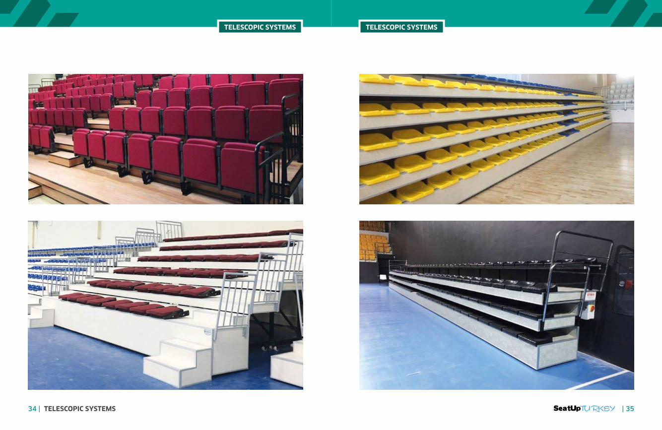
34 | TELESCOPIC SYSTEMS | 35

TELESKOPİK FRONT AND FRONT SIDE ISOMETRIC APPEARANCE
510,0000m
510,0000m
80,0000m
510,0000m
80,0000m
100,0000m
94,0000m
94,0000m
100,0000m
126,8600m
153,6500m
2. Platform Angle8 units
3. Platform Angle8 units
2. Platform Carrier8 units
1. Platform Carrier8 units
3. Platform Carrier8 units
1. Platform Kasa4 Adet
2. Platform Kasa4 Adet
3. Platform Kasa4 Adet
4 PCS 510 CM TELESCOPIC TRIBUNE
440,0000m
440,0000m
440,0000m
90,0000m
90,0000m
110,0000m
104,0000m
104,0000m
110,0000m
117,5000m
145,1000m
1. Platform Carrier 2units
2. Platform Carrier 2units
3. Platform Carrier 2units
2. Platform Angle2 units
1. Platform Safe1 unit
2. Platform Safe1 unit
3. Platform Safe1 unit
3. Platform Angle2 units
1 pc 440 CM TELESCOPIC TRIBUNE
TELESCOPIC TRIBUNE INSTALLATION GUIDE
TELESCOPIC SYSTEMS TELESCOPIC SYSTEMS
36 | TELESCOPIC SYSTEMS | 37

PLATFORM INSTALLATION
The platform frames are placed on the carrier feet as shown in the figure. Two M8x80 bolts and nutsare used at each foot for connection.After each platform frame is connected to its own legs, it is placed on top of each other in such a waythat it stands in line with the stands.
1
2
3
4
ELECTRIC MOTOR INSTALLATION
After the platform assembly is finished, there are 40x40 mm brackets for motor connectionbetween each platform rack in the first row. As shown in the figure, the motor case is insertedbetween the brackets and assembled using 4 M8x80 bolts and nuts. Once the engine has beenassembled, the wheels of the carrier feet and the wheels in the engine case are aligned toensure proper system operation.
CLAY PLATFORM ASSEMBLY
Two independent 510 cm platforms are mounted to each other with the helpof bolts and nuts M8x80 through the mounting holes in each step as shown. Inthis way, the two platform platforms are prevented from moving independentlyof each other.
6
5
CORNER ASSEMBLY AND FIXATION
Each carrier is connected to the connecting flanges at the rear of the foot and inthe middle of the 2nd and 3rd row platform casings as shown by 40x40 mmbrackets. M14x30 bolts are used for connection.After the specified assembly process is finished, it is placed in the field where thetribune is used and fixed at the place. Twisted L-shaped connecting brackets areused to secure them in place. As shown in the figure, L is mounted on one sidewith bolts in the rear wheel and on the other side with steel dowels, fixing is done.
7
8
CONNECTION LAMPS
9
TELESCOPIC SYSTEMS TELESCOPIC SYSTEMS
38 | TELESCOPIC SYSTEMS | 39

SEAT INSTALLATION
There are 192 different PVC seats and 18 different VIP seats. PVC seats are assembled in four groups as shown in the layout chart below, with 48being one. There is only one group for 18 VIP seats.The seat assembly is also made with the attachment markings on both seat versions. The connecting plates come out of the package with one sidemounted on the seat. The other part, which is empty, is equally spaced so as to correspond to the wooden part of the platform frame.
48 UNITS SEAT MODEL STADIUS111 - 4 GROUP
18 UNITS VIP SEATS - 1 GROUP
10
İ
İ İ İ
İ İ İ
İ İ İ
Ğİ
ELECTRIC PANEL CONNECTION SCHEME
TELESCOPIC TRIBUNE USE INSTRUCTION
- Be sure to read the operating instructions before
operating the platform!
- You provide environmental safety for the plat-
form.
- Open the cover of the telescopic tribune electric
panel and remove all the fuses inside.
- Check whether the telescopic tribune electrical
panel is receiving electrical power from the light
sensors on the panel.
- The platform is moved on the electric panel us-
ing the forward and back buttons.
- As long as the platform is moved forward (to
open the platform), the platform stops and stops
when the forward button is held down, and stops
when the back button is pressed to hold back the
platform.
- When the platform moves forward or backward,
close all the fuses in the electric panel and do not
forget to close the cover of the electric panel.
WARNING
- Other than the technical officers, interference
with the electric system is PROHIBITED. HIGH
VOLTAGE INCLUDED!
- During the opening or closing processes of the
telecopic tribune, there shall be no substance or
person on, under, in front of or around it.
- The maximum capacity of the telescopic tribunes
is 210 persons. Exceeding the capacity is DAN-
GEROUS and PROHIBITED!
- The telescopic tribunes must be fully open or
fully closed. Half-open use is DANGEROUS and
PROHIBITED!
TELESCOPIC SYSTEMS TELESCOPIC SYSTEMS
40 | TELESCOPIC SYSTEMS | 41

PROTABLE SYSTEM MINI STADIUM
PROTABLE SYSTEM MINI STADIUM PROTABLE SYSTEM MINI STADIUM
42 | PROTABLE SYSTEM MINI STADIUM | 43

PROTABLE SYSTEM MINI STADIUM PROTABLE SYSTEM MINI STADIUM
44 | PROTABLE SYSTEM MINI STADIUM | 45

www.seatupturkey.com.tr Seatup Turkey | Manufacturing Seating Solutions Catalogue 2020 - 2021

CONTACT INFO
Head office.
Altınova Mh. İstanbul Cd. Buttim iş Merkezi
C Blok No: 424/5 Ofis No: 3160 16250
Osmangazi, Turkey / Bursa
Mobil.
+90 542 719 67 12
Tel.
+90 224 999 67 07
Mail.
Related Documents