Minnesota Pollution Control Agency 520 Lafayette Road North St. Paul, Minnesota 55155-4194 651-296-6300 • 800-657-3864 2013 Stabilization Pond Systems Operations • Maintenance • Management

Welcome message from author
This document is posted to help you gain knowledge. Please leave a comment to let me know what you think about it! Share it to your friends and learn new things together.
Transcript

Minnesota Pollution Control Agency520 Lafayette Road NorthSt. Paul, Minnesota 55155-4194651-296-6300 • 800-657-3864
2013 Stabilization Pond SystemsOperations • Maintenance • Management

Minnesota Pollution Control Agency
520 Lafayette Road North | Saint Paul, MN 55155-4194 | www.pca.state.mn.us | 651-296-6300
Toll free 800-657-3864 | TTY 651-282-5332
wq-wwtp8-22
Authors
Original authors: Williard N. Sexauer, Roger V. Karn 2013 edition: Gene Erickson, Kay Curtin, Steve Duerre
Contributors to editions 1975, 1979, 1994, 1996, 1999
Janet Eckart, Gene Erickson, Linda Grant, Del Haag, Mike Herman, Dianne Navratil, Dwayne Nelson, Brian Roach
Acknowledgements
Wastewater training staff appreciate the attendees of stabilization pond training courses beginning in January, 1974; their comments and suggestions have been incorporated into this manual.
Editing and Graphic Design
Graphic design: Carol Pruchnofski, Nancy Ellefson
Editor: Nancy Ellefson
Cover photo: City of Albany, Minnesota
Courtesy of Stantec Consulting Services
The stabilization pond at Albany, constructed in 1955, was the first such system in Minnesota. The system was upgraded in 1984 with construction of the two pond cells in the background. The pre-aeration pond was added in 2001.

Stabilization Pond Systems Operation, Maintenance, Management | i
Forward
This manual was developed to help wastewater operators understand how wastewater is treated in stabilization ponds. It is intended to provide a comprehensive guide for an operator to follow during normal operation and maintenance. Although many practices covered in this manual can be used for all types of ponds, information does not specifically include aerated ponds, polishing ponds or storage lagoons.
This manual is NOT intended to replace various procedures and requirements contained in your NPDES permit; it only serves as guidance to the user. In cases where there are differences, your NPDES permit is the final governing document and should be relied upon for compliance purposes.
The manual is organized to follow the normal flow of wastewater after its discharge to a sanitary sewer system, including collection system operation and maintenance.
Disclaimer
Any references to commercial products are for illustration purposes only and do not constitute endorsement by the Minnesota Pollution Control Agency or the State of Minnesota.
Dedication
The Minnesota Pollution Control Agency (MPCA) began offering wastewater operator training in the early 1970s under the leadership of the operator training group’s first supervisor, Bill Sexauer. Bill’s vision included not only mandatory wastewater operator certification, but also specific training for stabilization pond operators and others. As a result, the first pond seminar was held in January, 1974. Because of Bill’s leadership and wisdom and based on experience from those seminars, this manual was first created in 1975. Although Bill passed away on March 14, 2010, his legacy of pond seminars continues.
This manual is dedicated to Willard (Bill) Sexauer.

ii | ©2013 Minnesota Pollution Control Agency All rights reserved.

Stabilization Pond Systems Operation, Maintenance, Management | iii
Contents
Contents1. Introduction to stabilization ponds ............................................ 1
2. Wastewater collection systems ................................................ 19
3. Lift stations ............................................................................... 29
4. Stabilization ponds treatment process ..................................... 37
5. Design criteria ........................................................................... 51
6. Stabilization pond operation .................................................... 61
7. Discharging stabilization ponds ................................................ 81
8. Maintenance ............................................................................ 95
9. Sampling and lab testing ........................................................ 109
10. Records and reports ............................................................... 117
11. Safety ...................................................................................... 125
12. Personnel ................................................................................ 133
13. Troubleshooting ...................................................................... 139
14. Appendix ................................................................................ 149
A: Pump calibration procedure & worksheet ........................ 151
B: Emergency notification ..................................................... 155
C: Solving word problems & design problems 1 & 2 ............. 157
D: Total days needed to discharge ......................................... 161
E: Discharge calculation worksheet ....................................... 163
F: Discharge evaluation report ............................................ 165
G: Dilution ratio worksheet ................................................... 167
H: MPCA regional offices ....................................................... 169
I: Various pond worksheets & spreadsheets ........................ 171
J: References and suggested resource material .................... 187

iv | ©2013 Minnesota Pollution Control Agency All rights reserved.

Stabilization Pond Operation and Maintenance | 1
1 — Introduction
1Introduction to Stabilization Ponds
Characteristics of wastewater ................................................ 3
Commonly-measured parameters .......................................... 5
Biological organisms ............................................................... 6
Overview of wastewater treatment ....................................... 7
Management and operator responsibility ............................ 13
Effluent quality limits............................................................ 14
Total Maximum Daily Load (TMDL) ...................................... 14
Unauthorized releases (bypassing) ....................................... 15
Upsets ................................................................................... 16
Effluent violation .................................................................. 17
Written reports ..................................................................... 17
Significant industrial users .................................................... 17
NPDES permit provisions ...................................................... 18
Public health concerns ......................................................... 18

2 | ©2013 Minnesota Pollution Control Agency All rights reserved.
1 — Introduction

Stabilization Pond Operation and Maintenance | 3
1 — Introduction
Chapter 1 — Introduction
Characteristics of wastewaterWastewater is water that has been degraded or contaminated. It generally contains 99.9 percent water and 0.1 percent solids. Sources of wastewater include:
• Human and animal wastes
• Household wastes
• Infiltration of ground water
• Inflow of surface waters (rain water)
• Various industrial wastes
Physical characteristicsThe physical characteristics of wastewater – color, odor, temperature, flow, solids – can tell you a lot about the type of waste you are receiving at your facility as well as warn you of developing problems.
• Color – The color of normal domestic wastewater is gray, resembling dirty dishwater. A black color may indicate septic (no oxygen) conditions or certain types of industrial loading. Many color variations can occur. If you know the source and nature of the wastewater, you can often use color as a tool to assist you in operating your facility.
• Odor – The odor of fresh domestic wastewater is often described as musty. A rotten egg odor (hydrogen sulfide) indicates septic conditions.
• Temperature – The normal influent temperature of domestic wastewater is a few degrees warmer than the water supply. Higher temperatures may indicate industrial cooling water discharges. Cooler water may indicate excessive infiltration or inflow water.
• Flow – The variation in flow in a community may be extreme, especially in smaller cities. The impact of this variation may cause severe problems depending on the type of wastewater treatment plant you operate.
• Solids – Wastewater is 99.9 percent water and 0.1 percent solids. It is the 0.1 percent solids that creates the need for wastewater treatment facilities.
Types of solidsSolids in wastewater are classified by their characteristics.
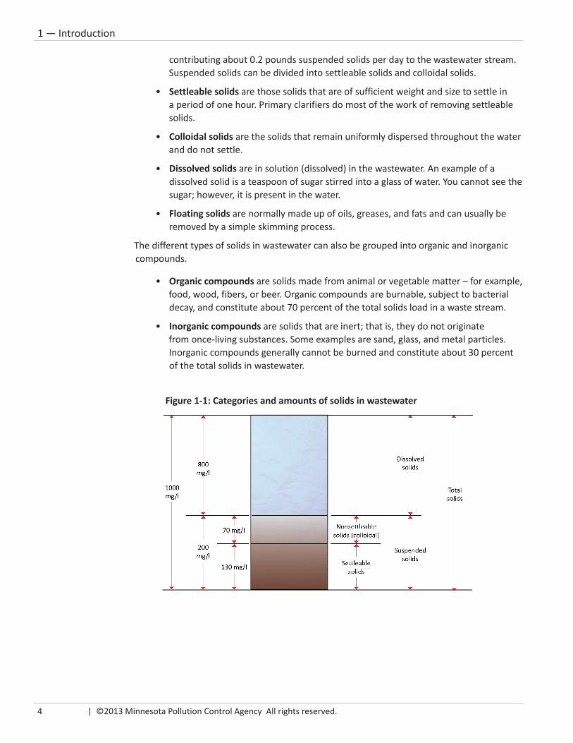
• Total solids includes all solids: suspended, dissolved, and floating solids. Each person contributes an average of 0.5 pounds of total solids per day to the waste stream.
• Suspended solids are visible; they are hanging (in suspension) in the water. They are normally removed by a sedimentation or filtration process. Typical domestic wastewater contains about 200-250 mg/L of suspended solids, with each person
4 | ©2013 Minnesota Pollution Control Agency All rights reserved.
1 — Introduction
contributing about 0.2 pounds suspended solids per day to the wastewater stream. Suspended solids can be divided into settleable solids and colloidal solids.
• Settleable solids are those solids that are of sufficient weight and size to settle in a period of one hour. Primary clarifiers do most of the work of removing settleable solids.
• Colloidal solids are the solids that remain uniformly dispersed throughout the water and do not settle.
• Dissolved solids are in solution (dissolved) in the wastewater. An example of a dissolved solid is a teaspoon of sugar stirred into a glass of water. You cannot see the sugar; however, it is present in the water.
• Floating solids are normally made up of oils, greases, and fats and can usually be removed by a simple skimming process.
The different types of solids in wastewater can also be grouped into organic and inorganic compounds.
• Organic compounds are solids made from animal or vegetable matter – for example, food, wood, fibers, or beer. Organic compounds are burnable, subject to bacterial decay, and constitute about 70 percent of the total solids load in a waste stream.
• Inorganic compounds are solids that are inert; that is, they do not originate from once-living substances. Some examples are sand, glass, and metal particles. Inorganic compounds generally cannot be burned and constitute about 30 percent of the total solids in wastewater.
Figure 1-1: Categories and amounts of solids in wastewater

Stabilization Pond Operation and Maintenance | 5
1 — Introduction
Commonly-measured parametersBecause a waste stream entering a treatment plant may have different physical characteristics, it is important to have some way of determining waste load quality. Measurable characteristics include:
• pH – pH is a measure of hydrogen ion concentration in a liquid indicating how acidic or alkaline the liquid is. It is measured on a scale from zero to 14; seven is neutral – neither acidic or alkaline. The pH concentration can affect biological activity. However, if the pH is within the range of six to nine, normal biological activity should not be affected.
• Dissolved oxygen (DO) is the oxygen concentration existing in a solution (dissolved) with water. It is available for fish to breathe and aerobic microorganisms to utilize. If not present at certain levels, aquatic life cannot be sustained. Dissolved oxygen can be added to water in several ways: by aeration equipment, turbulent flow, algae, or wind. Whatever the mechanism, dissolved oxygen is of major importance for good wastewater treatment.
• Temperature – as the temperature of water rises, its ability to hold dissolved oxygen decreases (see Table 1-1). Knowing how much oxygen water can hold (determined by its temperature), plus knowing the DO value present (after conducting a DO test), will determine whether you need to add more oxygen. The farther the DO value is below the holding capacity of the water, the more oxygen you can add. At zero degrees Centigrade and at sea level, the most oxygen that will dissolve in water is 14.6 mg/L. At 20 degrees Centigrade, the most oxygen is about 9 mg/L. However, because of excessive algal activity, stabilization ponds have been known to hold more than 14.6 mg/L (often as high as 25-30 mg/L). This condition of water holding more oxygen than normal is called super-saturation.
• Biochemical oxygen demand (BOD) – BOD measures the amount of oxygen needed by bacteria to decompose organic matter and some inorganic chemicals such as ammonia and nitrite under aerobic (in the presence of oxygen) conditions. Normal domestic wastewater contains about 200-250 mg/L of BOD with each person contributing about 0.17 pounds per day to the waste stream. The BOD test is conducted for a period of five days in an incubator at 20 degrees C. The higher the BOD, the more organic and inorganic pollutants are in the sample, and more oxygen is needed by the bacteria to decompose the organic material. The lower the BOD, the less pollutants in the sample; less oxygen is needed for decomposition. The term BOD is used both for the analysis and to describe the strength of the waste in terms of pollution potential.
• Carbonaceous BOD (CBOD) – CBOD analysis is similar to BOD analysis, except that before incubation, a chemical is placed into the sample bottle that inhibits the bacteria that nitrify, or break down the nitrogen compounds in the sample. This means only the remaining or carbon-based (carbonaceous) BOD will be analyzed by the test. Most pond systems in Minnesota report CBOD test results on their
Figure 1-2: pH scale

6 | ©2013 Minnesota Pollution Control Agency All rights reserved.
1 — Introduction
Discharge Monitoring Report (DMR), as nitrifying bacteria are not active in a pond system in cold weather. The CBOD test then gives a more accurate assimilation of
the breakdown of organic material in a pond system.
• Chemical Oxygen Demand (COD) – COD analysis, relies on the oxygen used during the breakdown of the organic and inorganic compounds in a sample containing chemicals, not bacteria like the BOD test. COD does not measure the oxygen-consuming potential associated with certain dissolved organic compounds, but it will give a quick estimate of the strength of a sample, which indicates its pollution potential. A COD test takes only two hours compared to five days for a BOD test, making it much more applicable for process control. Municipal facilities that accept septage or industrial waste use the COD test to determine a waste’s effect on the system before they allow it. Note that the COD test cannot be used for DMR reporting purposes.
• Total suspended solids (TSS) – TSS represent the portion of the total solids load that is not dissolved. To determine TSS, a specific volume of sample is poured through a pre-weighed filter pad. The filter pad is weighed again after drying in an oven at 103 to 105oC to remove all the water. The gain in dry weight (in milligrams) is then compared to the volume of sample (in milliliters) that was poured through the filter pad. The final results are expressed in milligrams per liter. TSS usually corresponds with BOD. If a sample tests high for TSS, the BOD usually tests high also. If the TSS result is low and the BOD result high, it may mean that the BOD is caused by dissolved organic or inorganic compounds.
Biological organismsOrganisms living in a waste stream can also be analyzed. Bacteria and algae are one-celled microscopic living organisms. They are similar in function and life processes to animals and plants. The number of bacteria in wastewater ranges from 2 to 20 million per cubic centimeter.
A waste stream contains many types of bacteria that can be classified in the following broad categories:
• Parasitic bacteria live at the expense of a host and depend upon the host for food and proper environmental conditions.
Table 1-1: Solubility of oxygen in water (mg/L)oC oF O2
oC oF O2
0 32.0 14.6 26 78.8 8.21 33.8 14.1 27 80.6 8.12 35.6 13.8 28 82.4 7.93 37.4 13.5 29 84.2 7.94 39.2 13.1 30 86.0 7.65 41.0 12.8 31 87.8 7.56 42.8 12.5 32 89.6 7.47 44.6 12.2 33 91.4 7.38 46.4 11.9 34 93.2 7.29 48.2 11.6 35 95.0 7.1
10 50.0 11.3 36 96.8 7.011 51.8 11.1 37 98.6 6.912 53.6 10.8 38 100.4 6.813 55.4 10.6 39 102.2 6.714 57.1 10.4 40 104.0 6.615 59.0 10.2 41 105.8 6.516 60.8 10.0 42 107.6 6.417 62.6 9.7 43 109.4 6.318 64.4 9.5 44 111.2 6.219 66.2 9.4 45 113.0 6.120 68.0 9.2 46 114.8 6.021 69.0 9.0 47 116.6 5.922 71.6 8.8 48 118.4 5.823 73.4 8.7 49 120.2 5.724 75.2 8.5 50 122.0 5.625 77.0 8.4 51 123.8 5.5

Stabilization Pond Operation and Maintenance | 7
1 — Introduction
• Pathogenic bacteria can be harmful because they can cause diseases. They grow within the body of the host and produce toxic or poisonous compounds that cause disease in the host.
• Saprophytic bacteria are the workers. They feed on dead organic matter and are the most important bacteria for treating wastewater.
• Algae are primitive plants, one or many-celled and usually aquatic, capable of producing their energy from carbon dioxide and water by photosynthesis. Algae normally found in stabilization ponds are essential because they are the principal suppliers of dissolved oxygen to the pond system.
Other microscopic and macroscopic organisms also exist in wastewater. Microscopic organisms (microorganisms) are too small to see without a microscope; they are present in both plant and animal forms. Microorganisms aid in decomposition, although they are not as abundant as bacteria. Macroscopic organisms are larger, more complex organisms that are visible to the naked eye. They play a part in the decomposition of organic matter. Viruses are also present but they do not play a part in treatment. However, like pathogenic bacteria, they cause a number of diseases.
Overview of wastewater treatmentThe primary purpose of wastewater treatment is to protect the health and well-being of the community. The goals of wastewater treatment include:
• Prevent disease and nuisance conditions
• Avoid contamination of water supplies and navigable waters
• Maintain clean water for survival of fish, bathing, and recreation
• Conserve water for all uses
Wastewater treatment is the process by which solids in the wastewater are partially removed and changed from complex organic solids to relatively stable organic solids that eventually settle out of the water. Summaries of the different types of wastewater treatment processes in use are discussed later in this section.
A wastewater treatment facility allows us to cleanse water under controlled conditions. Without a wastewater treatment facility, the cleansing process could occur naturally in a pond, lake or several miles of a flowing stream. However, by providing a wastewater treatment facility, we can prevent the degradation and pollution of these waters.
Natural cleansing is the ability of water to:
• Reduce bacterial content
• Satisfy BOD requirements of wastewater
• Stabilize organic material
• Return dissolved oxygen to normal levels
Figure 1-3: Algae in a pond system

8 | ©2013 Minnesota Pollution Control Agency All rights reserved.
1 — Introduction
This process occurs in four overlapping zones within a given body of water:
1. Degradation zone
2. Decomposition zone
3. Recovery zone
4. Clean water zone
The degradation zone is normally located directly below the discharge point and may show visible evidence of pollution.
The decomposition zone is characterized by anaerobic decomposition or putrefaction (septic – no oxygen – conditions). However, this zone may not exist if the volume of wastewater is small compared to the receiving water’s volume because dissolved oxygen may not be depleted.
The recovery zone is characterized by the reappearance of aerobic bacteria, fish, and other higher organisms.
Finally, the clean water zone occurs when the quality of the stream either is back to the original state or better than it was above the discharge point. Self-purification of water will accomplish approximately the same functions as a secondary treatment facility. However, neither process will remove metal pollutants.
There are many different types of wastewater treatment units that can be combined to form a variety of treatment facilities. Figure 1-4 is an overview of these units. Table 1-2 provides more detail about their purposes and mechanisms for providing treatment.
Figure 1-4: Wastewater treatment units

Stabilization Pond Operation and Maintenance | 9
1 — Introduction
Table 1-2: Treatment processes and function
Preliminary: Flow meter Measures and records flowScreening Removes roots, rags, cans and large debrisGrit removal Removes sand and gravel
Solids handling:
(Digester)Treats solids removed by other processes
Pre-aeration Freshens wastewater and helps remove oil
Primary: Sedimentation & flotation Removes settleable and floatable materials
Secondary: Biological processes Removes BOD and suspended and dissolved solids
Advanced (Tertiary):
Chemical & physical processes
Removes additional suspended and dissolved solids and nutrients
Disinfection Kills pathogenic organisms
Dechlorination Removes chlorine residual
Preliminary treatmentThe purpose of preliminary treatment is to remove some of the larger solids or debris that can clog or damage pumps, or interfere with subsequent treatment processes from the wastewater. Many different types of units are used. Bar racks, baskets and fine screens are designed to remove gross solid material for eventual disposal by incineration or disposal in an approved landfill. Comminuting devices (such as grinders, cutters, and shredders) are used to break or cut up solids so they can be returned to the wastewater without causing damage. Grit chambers are used to remove inorganic solids such as sand and gravel. Pre-aeration may or may not be used.
Primary treatmentPrimary treatment is designed to remove organic and inorganic settleable and floating solids by the physical process of sedimentation (settling). This is accomplished by reducing the velocity of the wastewater enough so that the solids settle out. The units that slow the water down and allow solids to settle are clarifiers and septic tanks. The removal efficiencies for these treatment units are about 90-95 percent of the settleable solids, 40-60 percent of the suspended solids, and 25-30 percent of the BOD.
Secondary treatmentSecondary treatment is used when wastewater has more organic solids (BOD) in suspension or solution than the receiving waters could accept if only primary treatments were utilized. Secondary treatment depends mainly upon aerobic (needing oxygen) organisms to biologically break down the organic solids in wastewater and produce stable inorganic and organic solids. This process is comparable to what happens in the recovery zone in a natural body of water.

10 | ©2013 Minnesota Pollution Control Agency All rights reserved.
1 — Introduction
There are several basic types of secondary treatment facilities:
• Trickling filter
• Activated sludge
• Stabilization pond
• Rotating biological contactor
• Membrane filter
• Subsurface sewage treatment system (SSTS)
Treatment systems are also classified as:
1. Suspended growth In suspended growth systems, the waste and microbes float in solution. Ponds and activated sludge are suspended growth systems.
2. Attached growth In attached growth systems, the microbes and waste are attached to a media of some type. Trickling filters and rotating biological contactors are attached growth systems.
In a trickling filter (which is not really a filter), the bacteria that live in a slime layer attached to the media in the filter break down the organic wastes (Figure 1-5). The natural flow of air between the rocks or the filter media supplies oxygen to the bacteria. Periodically, portions of the slime layer slough off the media and are removed in the secondary clarifier.
A rotating biological contactor (RBC) is similar to a trickling filter system (Figure 1-6). In a RBC, the filter media consists of large, circular plastic disks mounted on a rotating shaft. A
slime layer grows on the media like it does on a trickling filter. However, rather than being stationary, the media rotates in and out of the incoming wastewater. The bacteria get oxygen when they rotate out of the wastewater and are exposed to air. The slime layer also sloughs off and settles as sludge in the secondary clarifier.
When properly operated, a trickling filter and rotating biological contactor can normally reduce BOD by 65-85 percent.
In an activated sludge process (Figure 1-7), bacteria attached to the floc particles live in the aeration tank and break down the organic waste (BOD and TSS) suspended in the water. Mechanical aeration equipment provides oxygen to the bacteria. The floc
Figure 1-6: Rotating Biological Contactor
Figure 1-5: Trickling filter

Stabilization Pond Operation and Maintenance | 11
1 — Introduction
particles created in the aeration tank are allowed to settle in the secondary clarifier. They are then either returned to the aeration tank or wasted out of the system to a digester or other solids treatment. A properly operated activated sludge facility can reduce BOD and TSS by 80-95 percent.
In a stabilization pond system (Figure 1-8), bacteria that live in both the sludge layer and in the water break down the organic wastes. The algae living in the water provide the oxygen in this process. A properly operated stabilization pond system can reduce BOD by 80-95 percent.
Figure 1-8: Stabilization pond
Figure 1-7: Activated sludge process

12 | ©2013 Minnesota Pollution Control Agency All rights reserved.
1 — Introduction
When public sewers are not available, a subsurface treatment system (SSTS) may be used to treat wastewater for a cluster of homes. These systems, which are designed to treat sewage, not industrial wastes, require a NPDES permit (if over 10,000 gallons per day) and regular service by a certified operator. Homeowner associations may contract for operator services for their SSTS.
In a SSTS (Figure 1-9), wastewater flows first into a septic tank where solids separate from the liquid. Floatable solids, such as fats, float to the top forming a scum layer. Settleable solids sink to the bottom where they are partially decomposed by anaerobic bacteria. To maintain the system, the septic tank must be pumped periodically to remove the floatable and settleable solids.
Following the septic tank, an aerobic treatment tank (similar to an activated sludge or attached growth process) located after the septic tank provides secondary treatment to nitrify the effluent to remove ammonia. From there, the effluent generally is pumped through a network of perforated pipe into an absorption field composed of rock and soil for final disposal. Together they cause a biomat to form at the bottom of the trench to slow the release to the soil. The biomat is an organic layer that assists (along with the soil particles) in biologically treating the wastewater.
In some cases, after a disinfection process, the effluent may be discharged to a receiving water.
Tertiary or advanced treatment
Tertiary (advanced) treatment refers to a final treatment process, or additional treatment following a conventional secondary treatment system.
Polishing ponds are one form of tertiary treatment designed for further removal of BOD and total suspended solids (TSS). Spray irrigation, however, is normally designed only for nutrient removal. There are several forms of advanced treatment (such as chemical treatment and dual media filters) that can also be incorporated for solids removal, nutrient removal, or generally improved effluent qualities.
Figure 1-9: Subsurface sewage treatment system

Stabilization Pond Operation and Maintenance | 13
1 — Introduction
Sterilization and disinfection are not the same. Sterilization means to totally kill all organisms. In wastewater treatment, sterilization would be cost prohibitive.
Disinfection and de-chlorinationSecondary and tertiary treatment removes a majority of the BOD and TSS and some of the pathogenic organisms. Disinfection is needed to remove more pathogenic organisms. Disinfection means the destruction of only potentially harmful or pathogenic organisms – not all the organisms in the waste stream. There are two common methods of disinfection:
1. Chlorination (gas or liquid)
2. Ultraviolet light
Because chlorine is toxic, chlorination must be followed by a de-chlorination process to remove residual chlorine in the final effluent. Typically, sulfur dioxide, sodium metabisulfate or sodium bisulfate are used to remove chlorine residual. Disinfection using ultraviolet light involves routing treated wastewater through a tank containing bulbs that emit ultraviolet light.
Solids handlingThe methods for handling wastewater treatment solids have two functions:
• Reduce the volume of materials to be handled by removing some of the liquid portion
• Decompose the highly organic matter to relatively stable or inert organic and inorganic compounds from which water will separate more readily
Aerobic and anaerobic digesters and sludge lagoons are the units used in a facility to reduce volumes as well as decompose organic matter. Dewatering methods use gravity belt thickeners, belt presses, centrifuges, and drying beds or reed beds to evaporate the water.
Management and operator responsibilityOperation of a wastewater treatment system is a joint effort of the wastewater treatment facility owner and operator; each has certain areas of responsibility.
OwnerThe owner may be a private agency, governing board of a sanitary district or city council that had the treatment facility constructed. It is to this individual or group that the operator is ultimately accountable.
The owner must provide a certified operator who is conscientious, properly trained, and capable of operating and maintaining the facility after being given proper instruction and orientation. If the current operator leaves, the owner must obtain an immediate replacement. An owner should provide opportunities for plant personnel to expand their knowledge through attending training sessions with groups such as the Minnesota Pollution Control Agency, the Minnesota Wastewater Operator Association or Minnesota Rural Water Association.

14 | ©2013 Minnesota Pollution Control Agency All rights reserved.
1 — Introduction
The owner must establish a salary level that encourages tenure of trained and experienced personnel.
The owner must obtain from the appropriate regulatory agency any permit required for operation of the plant. The owner is ultimately responsible for the performance of the treatment facility. To maintain such performance, the owner must provide general supervision of the operator, and supply all necessary tools, materials, and parts for proper plant operation and maintenance. The owner must also provide adequate funds for plant maintenance and expansion as needed.
OperatorA pond operator is responsible for the conscientious and proper operation and maintenance of the installation. This includes maintaining buildings, grounds, and equipment.
The operator must conduct the tests and observations required for proper facility operation and regulatory reporting requirements. The operator should notify the owner of the results in terms that can be easily understood.
An operator must be able to interpret laboratory tests and use the results to control treatment plant operation.
An operator must inform the owner of the need for tools, parts and supplies, with sufficient advance notice to insure the items will be available when needed.
An operator must become fully acquainted with the plant and treatment process, become certified, and take advantage of training offered by the regulatory agency, an operator association, or local community college.
Effluent quality limitsThe National Pollutant Discharge Elimination System (NPDES) permit establishes effluent quality limits for all wastewaters discharged to surface waters of the state. The limits were calculated to prevent violation of water-quality standards for the receiving water. Typical limits for stabilization ponds are listed in Table 1-3. Ponds are allowed a controlled discharge to receiving waters only during the spring and fall periods when stream flow is usually higher. Some pond systems may have additional NPDES limits.
Table 1-3:Typical effluent discharge limits
Biochemical Oxygen Demand 25 mg/LSuspended solids 45 mg/LFecal coliform group organisms* 200 colony forming units (CFU)/100 mlpH range 6.0 — 9.0Phosphorus** 1.0 mg/L
*If system cannot produce effluent quality meeting fecal limits, disinfection may be necessary (stabilization ponds typically do not need disinfection)
**In addition, some pond systems also may have a maximum mass kg/year limit.

Stabilization Pond Operation and Maintenance | 15
1 — Introduction
Total Maximum Daily Load (TMDL)The federal Clean Water Act requires states to adopt water quality standards to protect lakes, streams, and wetlands from pollution. The standards define how much of a pollutant (bacteria, nutrients, turbidity, mercury, etc.) can be in the water and still meet designated uses, such as drinking water, fishing, and swimming. A water body is impaired if it fails to meet one or more water quality standards.
To identify and restore impaired waters, Section 303(d) of the Clean Water Act requires states to:
1. Assess all waters of the state to determine whether they meet water quality standards.
2. List waters that do not meet standards and update every even-numbered year.
3. Conduct TMDL (total maximum daily load) studies to determine what pollutant reduction goals are needed to restore waters.
Federal and state regulations and programs also require implementation of restoration measures to meet TMDLs.
Pond systems that discharge to an impaired surface water, watershed or drainage basin may be required to comply with additional permits or permit requirements in order to meet pollutant reduction goals established by a TMDL study. Requirements may include certain pollutant restrictions and monitoring. Your NPDES permit will indicate whether your facility must comply with specific TMDL requirements.
For more information about TMDLs, search the MPCA website (http://www.pca.state.mn.us) for TMDL. Also refer to the Clean Water Act — CWA303(d)(4)(A) — and the Code of Federal Regulations (CFR) at 40 CFR 122.44.I.2.i.
Unauthorized releases (bypassing)Except for conditions specifically described in your NPDES permit, all unauthorized bypasses, overflows, discharges, spills or other releases of wastewater or materials to the environment, whether or not intentional, are prohibited. However, the MPCA considers compliance with permit requirements, frequency of release, quantity, type, location, and other relevant factors when determining appropriate enforcement action.
Upon discovery of a release, a permittee must do the following:
1. Take all reasonable steps to immediately end the release.
2. Notify the Minnesota Department of Public Safety Duty Officer at 1-800-422-0798 (toll free) or 651-649-5451 (metro area) immediately upon discovery of the release. In addition, you should also contact your MPCA regional compliance staff during business hours at 1-800-657-3864. See Appendix B for emergency notification poster.
3. Recover as rapidly and as thoroughly as possible all substances and materials released or immediately take other action as may be reasonably possible to minimize or abate
If you discharge to an impaired waterbody, you may have additional requirements.

16 | ©2013 Minnesota Pollution Control Agency All rights reserved.
1 — Introduction
pollution to waters of the state or potential impacts to human health. If the released materials or substances cannot be immediately or completely recovered, contact the MPCA. If directed by the MPCA, consult with other local, state or federal agencies (such as the Minnesota Department of Natural Resources and/or the Wetland Conservation Act authority) for implementing additional cleanup or remediation activities in wetland or other sensitive areas.
4. Collect representative samples of the release immediately after discovery and test for parameters of concern. If needed, contact MPCA regional compliance staff during business hours to discuss sampling parameters and protocol. Collect fecal coliform bacteria samples if the release contains or may contain wastewater. If the release cannot be immediately stopped, consult with MPCA regional staff regarding additional sampling requirements. Collect samples for at least (but not limited to) two times per week for as long as the release continues.
5. Submit the sampling results as directed by the MPCA. At a minimum, submit the results to the MPCA with the next Discharge Monitoring Report (DMR) on a Release Sampling Report form. The form is available on the web page http://www.pca.state.mn.us/hqzqb28.
UpsetsWhen factors beyond operator control result in a system upset and temporary noncompliance with an applicable effluent limit, prepare to provide evidence showing:
• The specific cause of the upset
• That the upset was unintentional
• That the upset resulted from factors beyond reasonable control and did not result from operational error, improperly designed treatment facilities, inadequate treatment facilities, lack of preventative maintenance, or increases in production that are beyond the design capability of the treatment facility
• That the facility was properly operated at the time of the upset
• That the MPCA and Minnesota duty officer were properly notified of the upset according to requirements in the facility’s NPDES permit
• That remedial measures required by the facility’s NPDES permit were implemented
Immediately report discharge violations that threaten human health, drinking water or the environment.
Figure 1-10: Release sampling report page 1

Stabilization Pond Operation and Maintenance | 17
1 — Introduction
Effluent violationIf sampling indicates a violation of any discharge limit specified in your permit, immediately:
1. Make every effort to verify the violation by collecting additional samples, if appropriate
2. Investigate the cause of the violation
3. Take action to prevent future violations
4. Report immediately any violations that pose a threat to human health or a drinking water supply, or represent a significant risk to the environment
Report to the Minnesota Department of Public Safety Duty Officer at 1-800-422-0798 (toll free) or 651-649-5451 (metro area). In addition, you should also contact your MPCA regional office during business hours at 1-800-657-3864. Record the violations and the results of additional sampling on the next appropriate DMR.
Written reportsWith the next DMR, include a written report describing any release, bypass, upset, or permit violation that occurred in the previous month. Include in the report at least the following information:
1. A description of the discharge, including volume, duration, effluent characteristics (monitoring results), and receiving water
2. The cause of the bypass, upset, or violation and the steps taken to reduce, eliminate, and prevent its recurrence
3. The exact dates and times that the bypass, upset or violation occurred, and if it is still occurring, the anticipated duration of the bypass, upset or violation
4. Measures taken to reduce any adverse impact resulting from the bypass, upset, or noncompliance
5. For emergency bypass events, a description of any industrial and/or commercial users discharging high strength or toxic wastewater to the portion of the system from which the bypass has occurred
Significant industrial usersA significant industrial user (SIU) is an industry that meets one or more of the following criteria:
• Discharges 25,000 gallons per day or more of process wastewater
• Contributes a load of five percent (5%) or more of the capacity of the Publicly Owned Treatment Works (POTW)
• Is designated a SIU by you (the permittee) or the MPCA because it has a reasonable potential to adversely impact the POTW, or the quality of its effluent or residuals
As the permittee, you must establish pretreatment requirements for each significant industrial user.

18 | ©2013 Minnesota Pollution Control Agency All rights reserved.
1 — Introduction
You, as the permittee, must establish pretreatment requirements for each SIU. The level of pretreatment a SIU must meet is based on your permit requirements and limits. You must make sure that the SIU’s pretreatment is at a level that will ensure you are able to comply with applicable state and federal regulations and your permit limits.
To ensure the SIU is meeting the discharge requirements you establish, you or the SIU will need to do representative monitoring on both quantity and quality of the discharge. Monitor for the pollutants of concern on a schedule appropriate for the potential impact of the discharge.
If a SIU discharges during a calendar year, you must submit a Pretreatment Annual Report for that calendar year by January 31 of the following year. The MPCA has reporting forms available from the web page http://www.pca.state.mn.us/veizb30. Submit the report by January 31 to:
MPCA Attn: WQ Submittals Center 520 Lafayette Road North St. Paul, Minnesota 55155-4194
NPDES permit provisionsFollow facility operation, quality control and other provisions found in the guidelines in your NPDES permit. An operator should always read and understand the facility’s NPDES permit because it contains important information concerning the operation of the wastewater facility.
Public health concernsBoth the operator and the public must view stabilization ponds like any other wastewater treatment facility. Use caution and control to ensure public safety and health. Use stabilization ponds for their intended purpose only – not for public recreation.
The size of stabilization ponds is usually insignificant compared to the local natural water bodies. However, in some areas, stabilization ponds are the only sizable area of open water and are attractive to both children and adults for recreational purposes. Incidents of boating, ice-skating, extensive waterfowl hunting, and even swimming in ponds have been reported. You must prohibit recreational use and take steps to prevent it for safety reasons:
• Even though the efficiency of bacterial removal is very high, contamination or infection from pathogenic organisms is possible from contact with wastewater in a stabilization pond.
• Although most stabilization ponds attain a depth of only six feet, this is still deep enough for a person to drown.
Read your NPDES permit!

Stabilization Pond Operation and Maintenance | 19
2 — Wastewater Collection Systems
Wastewater Collection Systems
Types of collection systems .................................................. 21
Basic parts of a collection system ......................................... 22
Wastewater flow .................................................................. 22
Materials used in pipe construction ..................................... 22
Manholes .............................................................................. 23
Operation and maintenance ................................................. 24
Cleaning equipment ............................................................. 24
Inspection ............................................................................. 26
Smoke testing ....................................................................... 26
Design velocity ..................................................................... 26
Measuring velocities in gravity systems .............................. 27
2

20 | ©2013 Minnesota Pollution Control Agency All rights reserved.
2 — Wastewater Collection Systems

Stabilization Pond Operation and Maintenance | 21
2 — Wastewater Collection Systems
Chapter 2 — Wastewater Collection SystemsThe wastewater collection system is probably the oldest part of the wastewater facility. There is evidence of collection systems being used in India around 3750 B.C. The oldest sewer still in existence is an arched sewer built in Rome around the first century. It was used for carrying wastes from the Roman Forum to the Tiber River.
These old collection systems were all gravity-flow sewers. Although collection system are still designed for gravity flow, area topography often requires that lift or pumping stations be used to help get the wastewater to the treatment plant.
A major problem for collections systems is caused by inflow and infiltration – often referred to as I and I or I/I. The first I, inflow, is a direct connection to the collection system from sources such as roof drains, basement sump pumps and manhole covers. The second I, infiltration, is ground water seeping in through indirect connections such as joints and cracks in the collection system. Studies have shown that the majority of I/I is caused by inflow from private sources.
Types of collection systemsThere are generally three types of wastewater collection systems:
1. Storm sewers
2. Combined storm and sanitary sewers
3. Sanitary sewers
Storm sewersStorm sewers are the oldest type of collection system. They are used to carry runoff resulting from rain events and snow melt away from streets, parking lots, and developed areas.
Combined sewersThe combined collection system is the second oldest. During dry weather, this system carries wastewater; but during rain events, it is also used to carry away the stormwater. Some cities still may have combined sewer systems.
Sanitary sewersSeparate sanitary collection systems were first introduced in this country in the early 20th century. Their function is to collect and transport only domestic and industrial wastewaters to wastewater treatment plants.
Collection systems include storm sewers, sanitary sewers and combined sewers.

22 | ©2013 Minnesota Pollution Control Agency All rights reserved.
2 — Wastewater Collection Systems
Basic parts of a collection systemAll types of collection systems collect and convey wastewater using the following:
• Catch basins and curb inlets (not used with sanitary sewers) are chambers or openings built into the curb line of a street or parking lot to admit storm water into the storm water collection system.
• Lateral sewers (not used in storm sewers) are sewers that discharge into a branch or other sewer and have no other common sewer tributary into them. They are used to collect wastewater from individual homes or commercial and industrial facilities.
• Branch sewers collect discharges from homes and industries via the lateral sewers and then transport the wastewater to a main sewer. The minimum size of branch sewer is eight inches.
• Main sewers collect the wastewater from several branch sewers (serving several hundred acres) and convey it to an interceptor sewer.
• Interceptor sewers are normally large and receive flows from the main sewer and convey it to the treatment facilities.
• Force mains are pipes used to convey wastewater under pressure from the discharge side of a lift station.
Wastewater flowA typical collection system is designed to receive the present flows from domestic, commercial, and industrial sources as well as estimated future flows for at least 20 years. For domestic flow, the average for each person is 100 gallons per person per day. Commercial flows range from 2,000 to 16,000 gallons per day per acre. Industrial flows can reach up to 10,000 gallons per day per acre. Flow allowances of 100 gallons per inch of pipe diameter per mile of length per day are made for inflow from rainwater and infiltration from groundwater.
Materials used in pipe constructionCollection system pipe are made from either rigid or flexible pipe. Rigid pipe derives a substantial part of its load-carrying capacity from the structural strength inherent in the rigid
pipe wall. It will crack when subjected to a load or lack of support that exceeds the strength of the pipe. It will not return to its original shape. Flexible pipe derives its load-carrying capacity from the interaction of the flexible pipe and the soils affected by the deflection of the pipe. Flexible pipe bends or bulges when subjected to a load and then returns to its original shape, or close to it.
Collection system pipes are made of many different materials. The material is selected for its strength and its ability to resist deterioration from wastewater
and minimize infiltration and exfiltration (water leaving the pipe).
Collection system pipes may be flexible or rigid.

Stabilization Pond Operation and Maintenance | 23
2 — Wastewater Collection Systems
Examples of rigid pipe include:
• Vitrified clay pipe – VCP VCP was used extensively for constructing lateral and main gravity sewers for many years because of its ability to resist attack from the acids, alkalis, gases and solvents found in wastewater. In new construction, PVC pipe is now taking its place.
• Cast iron pipe (gray iron pipe) – CIP CIP is used in both gravity and pressure sanitary sewers. Because of its ability to resist crushing, CIPs are used for force mains, river, creek and bridge crossings, and in shallow trenches under streets where heavy traffic loads are expected.
• Asbestos cement pipe – ACP ACP pipes are watertight and resist abrasion and deterioration by most wastewater. Their major fault is their inability to resist corrosion caused by the acid formed by hydrogen sulfide. Do not use ACP in places or situations where hydrogen sulfide can be released.
• Reinforced concrete pipe – RCP RCP is used extensively when constructing stormwater collection systems and larger trunk and interceptor sewers in the sanitary collection system. Sometimes the inside of the pipe is coated with materials that resist corrosive action caused by the acids found or generated in wastewater.
Examples of flexible pipe include:
• Ductile iron pipe – DIP DIP is used for both gravity and pressure sewers. DIP is manufactured by adding either cerium or magnesium to cast iron pipe just before the pipe casting process.
• Polyvinylchloride pipe – PVC PVC pipe is flexible and resistant to most chemicals found in wastewater. PVC pipe is used for both gravity and pressure sewers, along with force main construction.
• Polyethylene pipe – PE PE pipe is used for pressurized lines where flexibility and resistance to bursting is desired. It is often used in climates where water may freeze in the line because its flexibility prevents rupture during freeze-thaw cycles. Pipe lengths can be readily assembled in the field by a machine that uses heat and pressure to fuse the ends of the pipe.
ManholesManholes are openings constructed to allow workers and equipment to access the sewer for cleaning and inspection. Manholes should have a minimum diameter of at least 48 inches and be located at the end of each line, at all changes in grade, size or alignment, and at all intersections. The distance between manholes should not exceed 400 feet for sewers 15 inches or less and 500 feet for sewers 18 inches to 30 inches. Distances up to 600 feet may be approved in cases where adequate modern cleaning equipment for such spacing is available.
Figure 2-1: Manhole cover

24 | ©2013 Minnesota Pollution Control Agency All rights reserved.
2 — Wastewater Collection Systems
Operation and maintenanceDo not just think about maintaining and inspecting the collection system – do it! For years, collection systems were maintained only on an emergency basis. Planned operation and preventive maintenance has been proven to increase the life of the system. It will also save taxpayer money by minimizing stoppages, and help you locate inflow and infiltration problem areas so you can fix them.
What should be done to ensure the system will operate smoothly – without blockages and without disrupting service? The following methods of operation should help in the operation and maintenance of your collection system. To make operating and maintaining your collection system easier:
• Show the location of all lines on readily available maps
• Make sure all lines are accessible and the rights-of-way are cleared
• Use good quality, undamaged materials in construction
• Use manhole spacing to determine the length of cables needed in a cleaning device
• Establish preventive maintenance procedures that include scheduled routine inspection and cleaning of the different parts of the wastewater collection system
• Clean troublesome areas more often as the situation dictates (Often ten percent of the total line will require 50 percent of the maintenance effort.)
• Continuously inspect for illegal connections and illegal discharges
• Repair known breaks before routine cleaning to avoid additional damage
Cleaning equipmentThe two methods for cleaning sewers are hydraulic or mechanical. Depending on the size of your collection system, you may want to rent or purchase some of the following equipment to help in operating and maintaining your system.
Hydraulic cleaning equipment includes the following, discussed in more detail below:
• Balling
• High velocity cleaners
• Flushing
• Poly pigs
BallingBalling involves pulling a manufactured ball with groves in it to create a head pressure and spinning or scouring action behind it. It is the least expensive and will remove grit/sand/grease in the collection system. It is not effective on roots.
Figure 2-2: Balls used in cleaning sewers

Stabilization Pond Operation and Maintenance | 25
2 — Wastewater Collection Systems
High velocity cleanersThe most popular piece of cleaning equipment today is a machine known as a jetter, jet cleaner, or high pressure cleaner. It opens stoppages and removes grease and debris from smaller diameter sewer lines by using a nozzle propelled by high velocity jets of water to cut and scour its way through the line. Some operators also use it to wash manholes and clean wet wells.
FlushingFlushing uses a surge of water to move light, decaying organic matter downstream in a slowly moving sewer line. If a fire hydrant it not convenient, it involves using a water truck and fire hose. Flushing is probably the least effective method of cleaning sewers.
Poly pigA poly pig is a soft flexible polyurethane ball that is pushed through a force main by pumping from the lift station. It is typically used to clean force mains by scouring the inside of the pipe.
Mechanical cleaning equipment uses the following:
• Power rodders
• Bucket machines
Power rodders A power rodder is a machine fitted with a steel rod with a device at the end. The rodder is pushed or pulled through the sewer. The device rotates as the rodder moves and cuts its way through blockages of grease, roots or other debris. Some devices used with the rodding machine are corkscrews, augers, root saws, sand leaders, porcupines, spear head, and last but not least, a Friday afternoon pick-up tool. A Friday afternoon pick-up tool is used to retrieve a rod that breaks during the process of clearing a blockage. At one time, the power rodder was the most widely used device for cleaning sewers.
Bucket machinesThe bucket machine is a specially designed power winch that is placed over manholes. It controls a traveling bucket that has one end open and a set of jaws on the opposite end. The bucket is pulled through the sewer from the jaw end. This keeps the jaws open and picks up debris. When the bucket is full, it is pulled back through the sewer by the opposite end. This closes the jaws and retains the debris. Once removed from a manhole, the debris in the bucket is dumped into a truck. The process is repeated until the line is clear. Bucket machines are mostly used to clean storm sewers
Figure 2-3: High velocity jet cleaner

26 | ©2013 Minnesota Pollution Control Agency All rights reserved.
2 — Wastewater Collection Systems
Inspection Inspecting a collection system will help you:
• Prevent leaks and blockages from developing
• Identify existing leaks
• Collect information to develop operation and maintenance programs
The most common way to inspect collection systems is television inspection. Televising provides instant and reliable real-time pictures on the overall condition of the system. Some municipalities own their equipment; others rent or contract to have their system televised.
Regular television inspection of a collection system can be valuable to discover the following:
• Possible upcoming blockages
• Broken pipe
• Protruding taps
• Inflow and infiltration locations
• Illegal connections
The camera is normally pulled in the direction of flow after the line has been cleaned.
Smoke testingSmoke testing of a collection system may be used to determine:
• Sources of inflow
• Proof of building connections
• Location of illegal connections
• Location of broken sewers
• Location of lost manholes
To conduct this type of work, you need a smoke blower, pipe plugs and a source of smoke, such as a smoke bomb or liquid smoke.
To avoid alarming the public, give advance notice that you will be using this procedure. Ensure you notify the local fire and police departments as well as community members who may be directly impacted.
Design velocitySewers are designed to convey wastewater at a minimum velocity of two feet per second during average daily flow or, at the very least, during peak daily flow. If the velocity is less than two feet per second, solids can settle in the line and eventually create a blockage. Problems can also occur if
Figure 2-4: Smoke test showing inlet location

Stabilization Pond Operation and Maintenance | 27
2 — Wastewater Collection Systems
Table 2-1: Minimum sewer slopes
Sewer-pipe diameter
Minimum slope in ft/100 ft
8 inches 0.4010 inches 0.2812 inches 0.2214 inches 0.1715 inches 0.1516 inches 0.1418 inches 0.1221 inches 0.1024 inches 0.0827 inches 0.06730 inches 0.05833 inches 0.05236 inches 0.04639 inches 0.04142 inches 0.037
the velocity is too high. Wastewater flowing too fast has a tendency to splash when forced to change directions in the sewer. Splashing allows the release of odors and gases that can accelerate the corrosion of concrete and metal structures in the sewer. To obtain minimum velocity, the minimum slopes given in Table 2-1 are recommended.
It is unlikely to achieve a velocity of two feet per second in the lines continuously. However, this minimum scouring velocity should be reached or exceeded during peak flows. In pressure-sewer lines, the velocities will be higher depending upon the number of pump stations operating.
Measuring velocities in gravity systemsProblems with sewer design, roots or other obstructions can slow down the velocity of wastewater. An operator can use dyes or floats to measure velocity to determine whether problems exist.
When used properly, dyes can be an effective way to estimate wastewater velocity.
1. Place a small amount of dye in an upstream manhole; note the time.
2. Record the amount of time between when the dye was inserted until you to see the dye at the downstream manhole (T1).
3. Also record the time from when you inserted the dye upstream until it disappears in the downstream manhole (T2).
4. Record the distance between upstream and downstream manhole.
5. Estimate the velocity using this formula:
Velocity (in feet per second) = 0.5 x Distance (in feet) (T1 + T2) (in seconds)
When using a float to determine velocity, use an easily recognized object, such as an orange ball or stick. To estimate the velocity, record the time it takes the float to travel a known distance and then use the following formula:
Velocity = 0.85 or 0.90 x Distance Time
Note: Because of friction of the water against the walls in the sewer line, the water velocity is not a true indication of the average velocity of all the water through the sewer. Engineers have determined that most of the water flowing through a sewer has a velocity of 85 to 90 percent of that of the surface water. To calculate the average velocity of the water in the sewer we have to reflect this difference in our formula by multiplying distance divided by time by 0.85 or 0.90. Use 0.90 for sewer pipes flowing at 100 percent capacity and 0.85 for sewer pipes flowing under 50 percent capacity.

28 | ©2013 Minnesota Pollution Control Agency All rights reserved.
2 — Wastewater Collection Systems

Stabilization Pond Operation and Maintenance | 29
3 — Lift Stations
3 Lift StationsLift station types ................................................................... 31
Lift station operation and maintenance ............................... 31
Flow measurement and recording ....................................... 33
Emergency operation ........................................................... 34
Influent line operation .......................................................... 35

30 | ©2013 Minnesota Pollution Control Agency All rights reserved.
3 — Lift Stations

Stabilization Pond Operation and Maintenance | 31
3 — Lift Stations
Chapter 3 – Lift StationsWastewater is conveyed to the primary pond(s) of a stabilization pond system either by a lift station and force main or by a gravity sewer. However, a force main directly into a primary pond is not allowed.
Lift station typesThe purpose of a lift station is to pump (lift) the wastewater to a higher elevation. Lift stations are placed in collection systems when the wastewater can no longer flow by gravity. There are many different types of lift stations in use:
• Submersible pump lift stations Submersible pump lift stations are the most common type of lift stations. They have a pump and motor completely submerged in a wet well. The centrifugal pump is watertight and controlled by floats, electrodes, air bubblers or microprocessors.
• Wet well/dry well lift stations In this type of pumping station, the pumps are located in a separate chamber (dry well) with only the suction pipe submersed in the wet well. Either floats or an air-bubbler pipe that senses the depth of the water in the wet well controls the pumps. Back pressure exerted on the air supply activates a pressure switch that starts the pumps. It is important that the dry well be well ventilated and dehumidified to protect the equipment and ensure the safety of the operator.
• Pneumatic ejectors A pneumatic ejector is used for small flows (less than 100 gpm) and low head. An inward-swinging check valve admits the flow to the bottom of an airtight pot. When the water fills to a certain level, it trips a signal to admit compressed air to the pot above the water. Then the wastewater is discharged through an outward-swinging check valve. This type of lift station is fairly maintenance free except for the chamber (pot), which is susceptible to corrosion caused by acids found and formed in wastewater.
Lift station operation and maintenanceThe pumps in a lift station convey the wastewater under pressure via a force main to the pond system. The pump design should allow the operator to maintain and repair the equipment without taking the lift station out of service. Remember that all types of lift stations require daily inspection. Regularly perform preventive maintenance to avoid operational problems and breakdowns.
Maintaining a lift station involves:
• General cleaning
• Lubricating according to manufacturers’ recommendations
• Checking the amount of pumping time on each pump to ensure equal operating time (If both pumps run together during high flows, you will need to check that time also.)

32 | ©2013 Minnesota Pollution Control Agency All rights reserved.
3 — Lift Stations
• Removing debris and grease that may accumulate in the wet well
• Cleaning floats and electrodes
• Inspecting check valves to make sure they are closing properly
Bar racks and comminutors and other solids removal equipmentPumps handling raw wastewater may be preceded by a bar rack or basket with openings of about two inches (barminutor). In some situations, comminuting devices (comminutors) are
incorporated to crush or grind debris so that it does not as easily damage pumps or downstream equipment. Using these pretreatment devices protects pumps and valves, thereby reducing repairs and replacements of treatment equipment further down the line.
Clean bar racks and baskets on a regular schedule so they perform according to design and avoid clogging and possible sewer back up. Properly store and dispose of screenings from bar racks and baskets to eliminate odor problems.
Regularly check comminuting devices and maintain them following manufacturers’ recommendations.
Other solids removal equipment, such as mechanical bar screens and grit removal systems, may be found in larger collection system lift stations.
Most stabilization pond systems do not have this type of equipment
DehumidificationElectrical controls, as well as other metal parts in a lift station, are subject to damage if exposed to excessive moisture. Using dehumidifiers to control moisture in lift stations can significantly reduce this problem.
Lift station ventilationProvide adequate ventilation in all lift stations to:
• Avoid building up excessive air pressure or vacuum above the wastewater in the wet well as the sewage rises or falls
• Prevent the accumulation of explosive, corrosive and lethal gases in the wet well
Dry well dewateringProvide a separate sump pump in the dry well to remove leakage or drainage from the dry well floor. All dry well floor and walkway surfaces should have adequate slope to drain liquids to the sump pump-collection point. The discharge point from the sump pump to the wet well must be above the high water level to eliminate the possibility of back siphoning into the dry well.
Figure 3-1: Bar rack

Stabilization Pond Operation and Maintenance | 33
3 — Lift Stations
Flow measurement and recordingA community must know, with reasonable accuracy, the amount of wastewater it is treating. This information is necessary to be able to:
• Compute operating costs
• Determine spring and fall discharge volume
• Determine seepage losses
• Estimate future expansion
• Complete monthly permit reporting requirements
• Evaluate treatment efficiency
Because of the need for accurate flow measurements, the MPCA requires an actual flow meter (such as a Parshall flume, magnetic meter, ultrasonic meter, etc.) for all new stabilization pond systems and existing systems that do not have a lift station. For those systems with a lift station, the use of running time meters will be acceptable until the pond system is upgraded. The capacity of each pump must be calibrated and the calibration recorded at least twice per year. Estimating flow from water usage is not acceptable because of the addition of immeasurable flow from infiltration (ground water) and inflow (rainfall and snow melt).
Parshall flume and v-notched weirsThese devices are one type of device used for measuring wastewater flows (other than for stabilization pond systems). They use an open channel to measure wastewater. The advantages of flumes are low head loss and self-cleaning ability.
Other methods of measuring liquids flowing in open channels and in pipes include, but are not limited to, a magnetic flow meter, diaphragm meters, ultrasonic meters, Doppler flow measurement, Kennison nozzles, and Venturi tubes.
Flow recordersFlow-recording devices normally are used in combination with measurement devices in flumes and weirs to provide a continuous, accurate record of flows. The measurement device is positioned in the water channel in a way that allows it to continuously sense the changing water levels passing through the flow-measuring structure. As the water level changes, the float, transducer, or bubbler sends a mechanical or electrical impulse to the recorder that records the flow on the programmable logic controller (PLC). The flow is recorded on a continual basis, usually in gallons per minute. Older systems may use charts that graph the flow over a 24-hour period. This information is used for checking peak and low flow conditions. Records provide a basis for determining inflow and infiltration problems, industrial user charges, and expansion needs.
If a composite sampler is used, the PLC also sends an electronic pulse to the sampler at pre-set amount intervals (such as every 10,000 gallons) to indicate that it should draw a sample.
Figure 3-2: Parshall flume

34 | ©2013 Minnesota Pollution Control Agency All rights reserved.
3 — Lift Stations
Running time meterFor stabilization pond systems, the most common method used in calculating influent flow is from the running time of the lift station pumps. The flow is calculated by multiplying the total time logged on each pump by the volume the pump will actually pump. The volumes of both pumps are added to obtain the total flow. During wet weather conditions, both pumps may run together at times. When that happens, a third running time meter is required. If
the high flow meter is running at the same time as the others, that time will be subtracted from the other meters running at the same time.
To ensure that measurements taken using running time meters are accurate, your NPDES permit requires you to calibrate the pumps at least twice a year to determine the actual gallons per minute pumped by each pump. You must also calibrate both pumps running together. To do this, follow the Pump Calibrations Procedure in Appendix A (Appendix A also contains a Pump Calibration Worksheet). Keep the calibration on file. Pump readings can be recorded on spreadsheets (see Appendix I for examples of spreadsheets). Worksheets and spreadsheets are also available on the MPCA website at http://www.pca.state.mn.us/f9ap8yx.
Emergency operationIn an emergency, lift stations must continue to operate – either by external electrical power, portable pumps or holding basins – to protect public health and prevent the discharge of raw wastewater to water bodies, basements, streets, or other public property. If wastewater is being released (bypassed), you are required to notify the Minnesota Duty Officer (see Appendix B).
Standby power supplyTo ensure an emergency power supply for lift stations, you can do one or more of the following:
1. Connect lift station to at least two independent utility sources.
2. Provide portable or in-place internal combustion engine equipment that will generate electrical or mechanical energy.
3. Provide portable pumping equipment.
NOTE: Place standby power units in operation for a short period every 30 days to ensure they will work properly when needed.
Holding basinsAnother method sometimes employed in an emergency is diverting wastewater to a holding basin. After electrical service is restored, the contents of the holding basin are fed back into the wet well as pumping capacity permits.
Figure 3-3: Running time meter

Stabilization Pond Operation and Maintenance | 35
3 — Lift Stations
Alarm systemsAll lift stations must have an alarm system. The alarm system activates in cases of power failure, pump failure, or any cause of lift station malfunction. Alarms must be connected to an automatic setup where various employees are on-call to respond to the situation in a very short time.
Electrical systemsSince many difficulties in operating a lift station can be caused by the electrical system, it is important that the operator is knowledgeable about basic functions of the system. Always use extreme caution when working around electricity. You will likely need the services of a licensed electrician.
Spare partsAvoid lift station down time by carrying a reasonable stock of spare parts that are subject to failure. Parts should include manufacturer recommended bearings, seals, filters and packing. Use of parts or lubricants not recommended by the manufacturer may damage equipment.
Influent line operationWastewater must enter the primary pond by means of a gravity sewer – not a force main. The wastewater is discharged horizontally at the bottom of the primary pond, at the midpoint of the width and two-thirds the length away from the outlet structure.
A horizontal and center discharge discourages short-circuiting and enhances the dispersion of solids throughout the primary pond(s), both of which are essential for good biological activity
In some older systems, wastewater is discharged directly to the primary pond via a force main. This is not allowed because, in the case of a break in the force main, the contents of the primary could be released back through the break. Also, many pond systems with an influent force main directly into the primary pond have experienced plugging because of solids buildup around the vertical riser at the end of the influent line.
MaintenanceWhen the force main is unusually long, it may have been designed larger than normal to reduce head loss due to friction and to help decrease pumping costs. Therefore, it may be advisable to turn on all the pumps in the lift station occasionally to increase the velocity of flow in the force main to help scour solids deposits that have accumulated during low flow or low velocity periods.
If wastewater flow to the ponds is by gravity, the influent line may accumulate solids. This will be especially true if the influent line comes into the primary pond with an elbow at the end. Grit and sand will accumulate around the vertical pipe outlet (elbow) and will
Figure 3-4: Wastewater enters at the bottom of the primary pond

36 | ©2013 Minnesota Pollution Control Agency All rights reserved.
3 — Lift Stations
eventually plug the pipe. Flush it out occasionally by closing the gate on the line at the dike and backing wastewater into the influent sewer of the pond and then suddenly opening it to create a surge of flow.
Stabilization Pond Operation and Maintenance | 37
4 — Stabilization Ponds Treatment Process
4Stabilization Ponds Treatment Process
Background and history ........................................................ 39
Types of pond systems ......................................................... 40
Advantages / disadvantages of pond systems ...................... 42
Bacterial classification of ponds ........................................... 42
Seasonal variations in stabilization ponds ............................ 43
Symbiotic cycle ..................................................................... 44
Factors affecting pond activity ............................................. 46

38 | ©2013 Minnesota Pollution Control Agency All rights reserved.
4 — Stabilization Ponds Treatment Process

Stabilization Pond Operation and Maintenance | 39
4 — Stabilization Ponds Treatment Process
Chapter 4 – Stabilization Ponds Treatment Process
Background and historyUsing a stabilization pond system as a secondary treatment for domestic and industrial wastewater is relatively new when compared with other forms of secondary treatment. However, experience and data from Minnesota pond systems have shown that when properly designed, constructed, operated, and maintained, a stabilization pond system is capable of producing an effluent compliant with National Pollutant Elimination System (NPDES ) permit limits. The only exception to this is meeting limits for total phosphorus and ammonia nitrogen. Biological conditions, such as cold temperatures that inhibit nitrification, will prevent a pond system from meeting ammonia nitrogen permit limits. Chemicals are needed to reduce total phosphorus to below NPDES permit limits.
The biological stabilization of wastewater in treatment facilities is similar to the biological stabilization process that occurs in a stream, pond, or lake. In these water bodies, observation has shown that wastewater stabilization takes place under both aerobic and anaerobic conditions. When designing a mechanical wastewater treatment facility, engineers try to provide conditions under which the biological stabilization process will occur in an environment bounded by concrete, steel, and mechanical devices. The same wastewater stabilization process that happens in a natural pond or lake may also be carried out in a stabilization pond under controlled conditions.
Both the conventional mechanical wastewater treatment facility and the stabilization pond system accomplish the same end results: protecting our natural streams and lakes from pollution and degradation by untreated domestic and industrial wastewater discharges.
Fessenden, North Dakota was the first municipality in the northern part of the United States to use a stabilization pond for wastewater treatment. This pond was developed in 1928 from a natural pond area. In 1949, Maddock, North Dakota designed and constructed the first man-made wastewater treatment pond in the Upper Midwest. The success of these installations, and the many others now in use, has led to the wide acceptance of stabilization ponds as a satisfactory wastewater treatment method in northern climates.
In 1955, the first installation in Minnesota was placed in operation at Albany. Plans and specifications for the original installations at Albany, Warren, and Breckenridge were approved by the State Water Pollution Control Commission (the predecessor to the Minnesota Pollution Control Agency) with the understanding that the ponds were to be considered an experiment and design changes might be required if pond operation was not satisfactory.
The installation at Albany was of special interest because milk waste constituted about 75 percent of the total strength of the wastewater it received. The Minnesota Department of Health
Figure 4-1: Albany ponds

40 | ©2013 Minnesota Pollution Control Agency All rights reserved.
4 — Stabilization Ponds Treatment Process
made a detailed study of the Albany pond during the first year and a half of operation. Results of samples collected from the ponds, together with physical observations, showed that operation was satisfactory based on conformance to design criteria. Treatment results at Albany and subsequent installations were sufficiently favorable so that stabilization ponds no longer are considered experimental, but are approved on the same basis as those for conventional mechanical treatment plants.
There are over 600 municipal wastewater treatment systems in Minnesota. Of those, a little less than half are stabilization ponds. These installations range considerably in size from a total of about 335 acres to less than 1 acre with an average size around 15 acres.
Types of pond systemsBecause of the many different applications of pond systems, it is important to define the different types of pond systems to avoid confusion in later discussions.
Stabilization pondA stabilization pond system is one in which the natural purification process occurs under controlled conditions with a discharge to surface water in the spring and fall of the year.
It is a secondary treatment facility designed to reduce wastewater solids and biochemical oxygen demand through settling and decomposition by the system bacteria. During the summer, algae in the pond primarily supply the dissolved oxygen required by the bacteria. During the winter, anaerobic conditions exist. Although stabilization ponds typically have a minimum detention time of 180 days, pond systems in north of an east-west line passing through Brainerd, Minnesota, are required to have a minimum detention time of at least 210 days.
Spray irrigation pondA spray irrigation pond is identical to a stabilization pond, except for two differences:
1. Treated wastewater is discharged to agricultural land when a cover crop that is not used for human consumption is actively growing
2. The minimum detention time for a spray irrigation pond increases to at least 210 days to allow for winter storage
Aerated pondAn aerated pond system also is designed to reduce wastewater solids and biochemical oxygen demand through settling and decomposition by the system bacteria. However, in an aerated pond, the dissolved oxygen required by the bacteria is supplied by mechanical aerators or diffused aeration.
This system can be designed for a continuous or controlled discharge. The minimum detention time for continuous discharge is 25 days. The detention time for a controlled discharge system is similar to that of a stabilization pond.
There are many types of pond systems.

Stabilization Pond Operation and Maintenance | 41
4 — Stabilization Ponds Treatment Process
Anaerobic pondAn anaerobic pond is designed to treat incoming waste under anaerobic (no dissolved oxygen) conditions throughout its entire depth. The process can be very odorous, but is highly efficient in destroying organic waste. Anaerobic ponds normally are used for treating biosolids, animal waste, or some types of industrial waste.
Polishing pondA polishing pond system follows a secondary mechanical treatment system. Its purpose is to:
• Further reduce the Biochemical Oxygen Demand (BOD) and Total Suspended Solids (TSS) before discharge
• Provide storage for controlled discharges or land application
• Possibly remove phosphorus
Polishing ponds often are considered a form of tertiary treatment. Their detention times vary between three and 210 days, depending on their purpose. Polishing ponds typically are non-aerated systems.
Infiltration pond or basinInfiltration ponds or basins are a series of shallow ponds or basins 0.5 feet to 1.5 feet deep used to dispose of treated wastewater. Operations normally consist of periodic controlled amounts to alternate shallow ponds with subsequent drying periods. Any remaining pollutant removal occurs by filtration, biological activity, and absorption as the effluent percolates through the soil. Depending on the location of the ground water, infiltration ponds may be designed with an underlying network of drains to collect and return the water back to the head works of the treatment system.
Industrial waste storage lagoonsIndustrial waste storage lagoons store high-strength wastes from processing operations such as vegetable canneries and beet sugar plants. The waste may have associated nuisance odors. Complete biological treatment usually is not accomplished in a lagoon, but may later be realized by an additional process such as land application or mechanical treatment. Generally, the main purpose of a storage lagoon is for the removal of settleable and floating solids.

42 | ©2013 Minnesota Pollution Control Agency All rights reserved.
4 — Stabilization Ponds Treatment Process
Advantages and disadvantages of stabilization pond systemsThe advantages and disadvantages of stabilization pond systems are listed below.
Advantages• Controlled seasonal discharges
• Lower construction and operation costs
• Accepts surge (excessive) flow more readily
• Low chemical and energy usage
• Very little (if any) sludge disposal problems
• Adaptable to land application of final effluent
• Lower mechanical failure potential
• Potentially increased design life
• Wildlife habitat
Disadvantages• Possible spring odors
• Larger land usage
• Operations somewhat dependent on climatic conditions
• Maintenance needed during busy times of the year
• Possible ground water contamination
• Potential for higher suspended solids (because of algae)
The term stabilization pond will be used to describe the process we are concerned with throughout this manual. When comparing different types of pond systems to the stabilization pond, many factors are similar. However, be careful about drawing conclusions from this manual that processes discussed apply directly to your specific system.
Bacterial classification of ponds In addition to classifying pond systems by type, they can also be classified according to the kinds of bacteria that are actively decomposing the organic waste. The bacteria are classified according to the form of oxygen (O2) they use to continue their life processes.
Aerobic bacteriaAerobic bacteria use dissolved oxygen for their life processes. Dissolved oxygen refers to oxygen molecules that are in solution (dissolved) within the water; e.g., fish also use this form of oxygen.
Not all processes discussed in this manual apply directly to your specific system.

Stabilization Pond Operation and Maintenance | 43
4 — Stabilization Ponds Treatment Process
Aerobic ponds are ponds that have dissolved oxygen distributed throughout the entire volume. An aerobic pond would not normally have a sludge layer. It receives its dissolved oxygen from algae. In the case of an aerated pond, it receives oxygen from mechanical aeration equipment.
Anaerobic bacteria Anaerobic means a condition in which free and dissolved oxygen are unavailable. Anaerobic bacteria grow only in the absence of dissolved oxygen. Anaerobic ponds are ponds that are void of dissolved oxygen throughout their entire content for the entire year. Anaerobic bacteria remove oxygen from sulfur compounds and in the process produce hydrogen sulfide (H2S). This very odorous and dangerous gas initially smells like rotten eggs. After a short period, H2S will numb your sense of smell.
During the spring, Minnesota stabilization ponds change from an anaerobic condition to an aerobic condition. As the ice melts, H2S and other gases are released. How long the anaerobic-to-aerobic process takes depends on weather, particularly wind action and temperature. Typically, the odorous condition lasts from 3 to 10 days. To avoid odor problems in an anaerobic pond system, a cover is installed on the pond, such as a crust of heavy scum, hay, straw, or a manufactured cover.
Facultative bacteriaFacultative bacteria can use dissolved oxygen or combined oxygen. They are able to adapt to changing oxygen conditions and continue decomposition while a system changes from aerobic to anaerobic, or anaerobic to aerobic.
Facultative ponds contain an aerobic zone and an anaerobic zone, with a facultative or transition zone in between.
Stabilization pond systems in Minnesota are classified as facultative ponds because communities of aerobic, facultative, and anaerobic organisms work together to decompose the waste.
Seasonal variations in stabilization pondsMinnesota climactic conditions change drastically from summer to winter and winter to summer. This change greatly affects the design and operation of pond systems.
SummerAlgae produce the maximum amount of oxygen during the summer months and wind mixes it into the water. The result is that most of the upper layer of a pond will be an aerobic zone. A facultative zone would occupy the middle area, with an anaerobic zone existing in the sludge layer on the pond bottom.
Anaerobic bacteria grow only when there is no dissolved oxygen.

44 | ©2013 Minnesota Pollution Control Agency All rights reserved.
4 — Stabilization Ponds Treatment Process
WinterAlgae die off in the winter and the ice cover prevents wind action and the oxygen that they provide. Since the source of oxygen has been eliminated, in winter the pond would be primarily or totally anaerobic.
Spring and fallSpring and fall are transitional periods. In spring, algae begin to grow and produce oxygen. With the addition of wind action, both will convert the pond from anaerobic to aerobic conditions. In fall, algae die off, so the aerobic zone decreases until the pond becomes ice covered and reaches winter anaerobic conditions.
Symbiotic cycleA complex community of microorganisms stabilizes wastewater in a pond system. Stabilization is a mutually beneficial interaction, or symbiotic relationship between bacteria and algae. In proper combination, objectionable characteristics of wastewater disappear. This mutually beneficial interaction is called the symbiotic cycle (Figure 4-2).
BacteriaBacteria are a group of microscopic organisms that lack chlorophyll and use organic nutrients as a food source. One might think of them as very small animals that need the same basic requirements as any animal: home, food, oxygen and water. Although many other organisms play vital roles in pond operation, bacteria are mainly responsible for the biological oxidation of wastewater in stabilization ponds, just as they are in trickling filters or activated sludge aeration tanks. Biological oxidation is the process in which microorganisms oxidize organic compounds, partially or completely, to carbon dioxide and water.
Bacteria and other pond organisms accomplish this by decomposing and digesting the organic matter in the pond. In the process, they use oxygen as the oxidizing agent, obtain the energy they need to sustain their life processes, release carbon dioxide and clean the water.
Obviously, this process requires the presence of oxygen in the dissolved form since oxidation can occur only under aerobic conditions. The utilization of molecular oxygen by bacteria and
Figure 4-2: Symbiotic cycle

Stabilization Pond Operation and Maintenance | 45
4 — Stabilization Ponds Treatment Process
other microorganisms is called aerobic respiration. Respiration is a process by which living organisms or cells take in oxygen from the air or water and utilize it to oxidize food and give off by-products, especially carbon dioxide. The role of these organisms in the ecology of the pond is similar to that of oxygen-breathing animals in the total balance of animals and plants in nature.
The breakdown of complex organic compounds (such as carbohydrates, fats, and proteins) by aerobic bacteria produces simpler inorganic substances: carbon dioxide (CO2), ammonia (NH3), nitrates (NO3), nitrites (NO2), phosphates (PO4) and other nutrients required by algae for various life processes.
AlgaeUnlike bacteria, which are part of the animal kingdom, algae are a very large and diverse group of simple, autotrophic organisms. Autotrophic means that they produce complex organic compounds like carbohydrates, fats and proteins from simple substances using energy from light (photosynthesis) or inorganic chemical reactions (chemosynthesis). Algae contain chlorophyll (the green plant enzyme), which uses sunlight for energy to convert carbon dioxide and inorganic substances to oxygen through the photosynthesis process. One can think of algae as very small plants. All types of algae have the same basic requirements: sunlight, C02, nutrients, and water.
Through photosynthesis, algae use carbon dioxide to produce the free or dissolved oxygen that helps maintain the aerobic system and support bacteria. Producing the major portion of the dissolved oxygen is the most important role algae perform in the pond. On a normal summer day, each pound of algae is capable of producing about 1.6 pounds of oxygen in a healthy active pond.
During the daytime, algae consume carbon dioxide and other nutrients and produce oxygen. This process raises the pH level of the pond. At night, algal respiration produces carbon dioxide – a process that lowers pH. Most algae, also called phytoplankton, are swimming or floating, unicellular or colonial, microscopic organisms. Although exceedingly small, these organisms often exist in sufficient quantity to give ponds a green tint.
During the stabilization process, most of the non-settleable organic matter in wastewater changes to a material that settles. Most wastewater solids, bacterial mass and algal mass eventually accumulate on the bottom of the primary and secondary ponds, forming a sludge layer. The sludge layer varies in depth from summer to winter. The depth increases in winter because biological activity decreases. In a properly functioning pond, sludge build-up should not be a problem over the design life of the facility. However, inorganic solids such as grit and sand may have to be removed around the inlet line and along the pond bottom area closest to the dike slope of the primary pond(s). The anaerobic decomposition process that occurs in the sludge layer is very efficient because of the long detention time; it results in almost total organic matter destruction.
Algal production of oxygen during daytime raises pH in the pond.
Figure 4-3: Sludge decomposition in late spring, summer and early fall
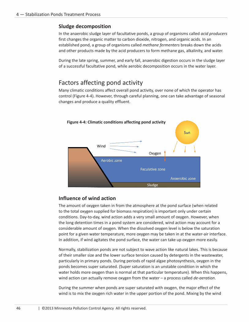
46 | ©2013 Minnesota Pollution Control Agency All rights reserved.
4 — Stabilization Ponds Treatment Process
Sludge decompositionIn the anaerobic sludge layer of facultative ponds, a group of organisms called acid producers first changes the organic matter to carbon dioxide, nitrogen, and organic acids. In an established pond, a group of organisms called methane fermenters breaks down the acids and other products made by the acid producers to form methane gas, alkalinity, and water.
During the late spring, summer, and early fall, anaerobic digestion occurs in the sludge layer of a successful facultative pond, while aerobic decomposition occurs in the water layer.
Factors affecting pond activityMany climatic conditions affect overall pond activity, over none of which the operator has control (Figure 4-4). However, through careful planning, one can take advantage of seasonal changes and produce a quality effluent.
Influence of wind actionThe amount of oxygen taken in from the atmosphere at the pond surface (when related to the total oxygen supplied for biomass respiration) is important only under certain conditions. Day-to-day, wind action adds a very small amount of oxygen. However, when the long detention times in a pond system are considered, wind action may account for a considerable amount of oxygen. When the dissolved oxygen level is below the saturation point for a given water temperature, more oxygen may be taken in at the water-air interface. In addition, if wind agitates the pond surface, the water can take up oxygen more easily.
Normally, stabilization ponds are not subject to wave action like natural lakes. This is because of their smaller size and the lower surface tension caused by detergents in the wastewater, particularly in primary ponds. During periods of rapid algae photosynthesis, oxygen in the ponds becomes super saturated. (Super saturation is an unstable condition in which the water holds more oxygen than is normal at that particular temperature). When this happens, wind action can actually remove oxygen from the water – a process called de-aeration.
During the summer when ponds are super saturated with oxygen, the major effect of the wind is to mix the oxygen rich water in the upper portion of the pond. Mixing by the wind
Figure 4-4: Climatic conditions affecting pond activity

Stabilization Pond Operation and Maintenance | 47
4 — Stabilization Ponds Treatment Process
also distributes influent wastewater throughout the pond. Because of mixing, food, dissolved oxygen, and organisms are in close proximity and the entire pond becomes an active, biological wastewater treatment facility.
Influence of lightBecause the process of photosynthesis relies on light, light is indispensable in the production of oxygen in the stabilization process. Three different, but related considerations help determine how well a pond operates and the area and depth needed for proper operation.
1. Latitude, elevation and cloud cover causes a regional variation in the amount of sunlight received during a year. Normally, for most of Minnesota, the amount of annual sunshine is about 50 to 60 percent of the total possible.
2. More importantly, seasonal change in Minnesota affects the amount of daily sunlight. Normally, summer sunshine is about 70 percent of the total possible; winter sunshine about 40 to 50 percent of the total possible.
3. How deep light can enter a pond determines how much of the pond participates in making oxygen. It also determines the best pond depth for optimum operation. Up to 30 percent of sunlight is lost when it reflects off the pond surface; more is lost when wind roughens the pond surface. How deep light penetrates the pond also depends on the amount of algae in the pond; the more algae, the less light penetrates. The amount of algae in a pond varies seasonally and from pond to pond. Studies have shown that at pond depths of more than three feet, the amount of oxygen produced is less than the amount needed. Water deeper than three feet must get oxygen by vertical mixing from wind action. For all these reasons, the best depth for operating a pond is between two and six feet.
Influence of temperaturePond temperature changes with the seasons and the amount of sunlight it receives. Generally, as temperature decreases, the rate of biochemical oxygen demand (BOD), the kind and amount of algae, the amount of bacterial activity and the rate of respiration all decrease as well.
The only thing that increases is the dissolved oxygen saturation value; colder water can hold more oxygen. Just before and after ice cover, water holds almost twice as much oxygen as it does in summer. When ice is not present and before algae begins to grow, the amount of oxygen taken in at the pond surface is an important source to supply oxygen demand during cold weather.
If a pond system is required to meet nitrogen limits during the spring discharge period, cold water may cause violations. Water temperature below 7°C (44°F) will disrupt nitrification, as the nitrifying bacteria only work in warmer temperatures. Higher flows, less mechanical aeration, and deeper ponds may keep temperatures warmer, but stabilization ponds will always have less ability for biological nitrification than other types of wastewater treatment facilities because of cold water temperatures.
As temperature decreases, biological processes within the pond slow down.

48 | ©2013 Minnesota Pollution Control Agency All rights reserved.
4 — Stabilization Ponds Treatment Process
Influence of nutrientsEnough nutrients must be available in a stabilization pond to support a healthy biological community of bacteria and algae. Municipal wastewater usually contains enough carbon, nitrogen, phosphorus and trace nutrients to support algal growth. In theory, aerobic treatment requires a BOD to nitrogen to phosphorus ratio of 100:5:1. The ratio in domestic wastewater is generally 100: 17:5, indicating that adequate nutrients are available. If the municipal wastewater contains a large volume of industrial waste that lacks these nutrients, the operator may need to add nutrients to make sure the biological growth and treatment processes take place.
Daily fluctuationsChanges in sunlight and air temperatures over a 24-hour period cause daily variations in pond temperature, dissolved oxygen concentration, pH, and other characteristics, as shown in Figure 4-5. Daily highs in dissolved oxygen may be 200 percent of saturation, while nighttime lows may approach zero. Daily fluctuations in pH, reaching as high as 10 during the day, are connected to the amount of carbon dioxide the algae use in the photosynthesis process:
1. Photosynthesis produces dissolved oxygen and uses up carbon dioxide.
2. Removing carbon dioxide reduces the acidity of the water.
3. As the acidity is reduced, the pH rises.
How much the pH rises depends upon the overall water hardness and alkalinity. The higher the hardness, the higher the pH will rise. The greater the alkalinity, the more resistance there will be to a change in pH.
Figure 4-5: Daily fluctuation in a stabilization pond

Stabilization Pond Operation and Maintenance | 49
4 — Stabilization Ponds Treatment Process
Yearly variation in stabilization pond activityWhen biological activity changes from winter conditions (anaerobic) to summer conditions (aerobic) is usually considered the objectionable time when hydrogen sulfide odors may be evident. This transition takes between three and ten days for most stabilization pond systems. During the summer and the summer-to-fall transition from an aerobic to anaerobic condition, odors should not be present. These two transition periods that occur in ponds in our northern climates must be considered when designing and operating ponds. The yearly variation is shown in Figure 4-6, and seasonal variations are shown in Figure 4-7.
Summer conditions
Remember that in summer, algae supply a large amount of dissolved oxygen through the photosynthesis process, so the pond is operating aerobically. This is the time when the pond is most active – that is, when most of the organic matter is decomposed. During this time, the sludge layer that accumulated during the winter is also decomposed by the anaerobic organisms living at the bottom of the pond.
A discharge during the summer would probably not meet permit limits because of a higher pH and large amount of suspended solids caused by algae.
Winter conditions
In the winter, ice and snow cover stops the sunlight and oxygen absorption from the atmosphere. Since dissolved oxygen is not available for aerobic decomposition, anaerobic decomposition of wastewater solids now takes place. Anaerobic biological activity is slow because of the low temperature of the wastewater in the pond. Because of this, a thicker sludge layer develops. When ice covers the pond completely, odorous gases (typically hydrogen sulfide) form because of anaerobic decomposition build up under the ice and continuously dissolve into the pond water.
A discharge during this time would probably not meet permit limits because of excessive BOD and fecal coliform.
Figure 4-6: Yearly variation in a stabilization pond

50 | ©2013 Minnesota Pollution Control Agency All rights reserved.
4 — Stabilization Ponds Treatment Process
Spring and fall conditions
In Minnesota, optimum times for discharging stabilization ponds are in the spring and fall. At these two times, called discharge windows, the system should be able to meet the majority of the permit limits and be able to discharge. Because of unpredictable weather in the spring, the spring discharge window is about two weeks shorter than the fall discharge window. In addition, the spring discharge window presents other difficult issues:
• If excessive snow melt occurs, influent flow increases because of inflow and infiltration. Increased influent flows do not allow sufficient time for the aerobic state to occur. A discharge could have BOD, DO, and fecal coliform violations because adequate aerobic decomposition has not yet taken place.
• Another problem is that the receiving waters may still be ice covered. A discharge to ice-covered receiving waters is not allowed.
• Additionally, the change from anaerobic to aerobic causes an increase in available phosphorus in the water. This results in an increase in total phosphorus and total suspended solids because of algae. The suspended solids test filters a sample of
wastewater, and re-weighs the solids in the sample. The algae do not go through the filter and are added weight, giving a higher TSS result. The algae also die and add to the sediment (sludge) layer on the bottom, causing the sludge to be removed more frequently. The older the pond system, the more phosphorus will be in sludge in the bottom of the pond.
During each of these discharge windows, an operator must release enough treated water to provide ample storage until the next discharge window. For some, this may mean only one discharge; others may need two, three, four, or even as many as five discharges during each discharge window.
These discharge windows do not apply to spray irrigation systems. Those systems must spray enough treated wastewater during the summer months when the cover crop is actively growing to provide enough storage capacity for the winter until they can spray again the following year.
Figure 4-7: Seasonal variations in a stabilization pond

Stabilization Pond Operation and Maintenance | 51
5 — Design Criteria
5Design CriteriaArea and loadings of the primary pond(s) ............................ 53
Storage capacity ................................................................... 53
Multiple units ....................................................................... 53
Location ................................................................................ 54
Soil and seal .......................................................................... 54
Water balance ...................................................................... 56
Embankments and dikes ....................................................... 56
Fencing and signs ................................................................. 57
Control structures and piping ............................................... 57
Other items needed ............................................................. 59
Design calculations ............................................................... 59
Pond depth ........................................................................... 59
Pond bottom elevations differences..................................... 59

52 | ©2013 Minnesota Pollution Control Agency All rights reserved.
5 — Design Criteria

Stabilization Pond Operation and Maintenance | 53
5 — Design Criteria
Chapter 5 – Design CriteriaMany factors affect pond operation, such as total area, loading, depth, storage capacity, and weather-related (climatic) conditions. Probably the most important factors affecting pond design are organic and hydraulic loading and area climatic conditions. Minnesota climatic conditions dictate less allowable loading than that of southern states.
In December 2009, the MPCA published Recommended Pond Design Criteria, which provides guidance on design standards for Minnesota stabilization and aerated pond systems. The publication is offered as a guide for engineers who design pond systems. The following discussion includes some of the more important items to be considered in wastewater (non-aerated) stabilization pond design. To view the guidance document, see the MPCA website at http://www.pca.state.mn.us/publications/wq-wwtp5-53.pdf.
Area and loadings of the primary pond(s)Generally, one acre of primary pond is provided for approximately 100-130 design population/population equivalent. BOD loading should not exceed approximately 22 pounds per day per acre (0.5 pounds per day per 1000 square feet) of primary pond(s) surface area.
Aerated systems loading rates are determined on a peak monthly basis, which may be characterized by industrial users or other sources, to maintain a specific level of dissolved oxygen within the aerated pond system.
Storage capacityBoth the average surface area and maximum operating depth of all ponds determine the storage capacity of a pond system. Since treatment efficiency is greatly reduced during the period of ice cover (about five to six months in Minnesota), pond systems are designed with enough capacity to store the entire wastewater flow for this period plus additional capacity to allow time for the winter to summer transition. The 180-day minimum storage capacity is calculated based on the volume between the two-foot level and the maximum level (not to exceed six feet in the primary and secondary pond). For Minnesota facilities located north of an east-west line traveling through Brainerd and for spray irrigation facilities, the minimum detention time is 210 days.
Multiple unitsAt a minimum, stabilization pond systems should contain three ponds: two primary ponds and one secondary pond. For flexibility, the primary ponds are arranged to allow the ponds to operate in either series or parallel. A two-pond system may be allowed if the horizontal surface area of dikes (toe-to-toe) of a three-pond system is greater than or equal to the pond water surface area. If a proposed
Figure 5-1: Typical pond system

54 | ©2013 Minnesota Pollution Control Agency All rights reserved.
5 — Design Criteria
system is a two-pond system (one primary and one secondary), the total overall size of both ponds cannot exceed ten acres. The ten acres is measured at the mean operating depth. There must be an adequate elevation difference between primary and secondary ponds to allow gravity filling of the secondary pond. The secondary pond bottom elevations must be at least four feet lower than the primary pond bottom elevations. If sufficient elevation difference is not available, a pump must be provided with sufficient capacity to remove at least six inches per day from the upstream pond.
In the pond system, the secondary pond must have a capacity of one-third the volume of the entire system and able to operate in series with the primary pond(s). This means that in a two-pond system where both ponds are equal depth, the primary pond should be twice as big as the secondary. For a three-pond system and larger, all ponds should be at least equal in capacity. The secondary pond is a storage pond used in preparation for discharge.
Secondary ponds are of particular value in reducing the carryover of algae and nutrients as well as wastewater bacterial counts. Secondary pond size is important because of the time needed to complete all the necessary discharges. At design flow, it will take about 66 days to discharge a properly sized secondary pond three times, assuming a difference between the primary and secondary pond bottoms of at least four feet (see Table 5-1). If this distance is not available, a pump will be needed to pump six inches per day from the upstream pond.
LocationThe location of stabilization ponds should be given as much consideration as that of conventional wastewater treatment facilities. The major objection to a wastewater treatment facility, particularly stabilization ponds, is based on aesthetics. Just like conventional facilities, stabilization ponds may develop nuisance odors when a portion of the process is out of balance. Normally, the only period of noticeable odor will be for about three to ten days during the winter to summer transition. Locate stabilization ponds, like other wastewater treatment facilities, as far as practical – and, when possible, downwind, from existing and future residential and commercial development. One-fourth mile from the nearest dwellings or occupied residence and one-half mile from a city or cluster of residences are recommended. The area should also be open and not surrounded by trees or hills that may impede wind action.
Also, consider flood plain, prevailing winds and karst topographical areas when choosing a location.
Soil and sealThe soil at the proposed pond site is important when determining the economic feasibility of ponds. Locate ponds where there is a separation of at least four feet between the top of the pond seal and the maximum high water table. In areas where bedrock is present, the required separation is a minimum of ten feet between the top of the seal and bedrock formation.
Table 5-1: Secondary volume vs discharge time
Secondary volume
(% of total vol)
Actual flow (% of design)25% 50% 75% 100%
20% 34 62 90 11525% 14 40 66 9233% 12 36 60 66

Stabilization Pond Operation and Maintenance | 55
5 — Design Criteria
Pond systems constructed after March 16, 1975, must be sealed and have seepage rates of no more than 500 gallons per acre per day. For ponds constructed before that date, acceptable seepage rates are 3,500 gallons per acre per day or less. If any reconstruction is done, the system must meet the 500 gallons per acre per day requirement.
For clay seals, a minimum thickness of 12 inches is required and is applied in lifts of no greater than six inches. For synthetic liners, a minimum thickness of 30 mils is acceptable. A mil is one thousandth of an inch (0.001 inches). (For comparison, a human hair is approximately 2 mils thick.) Either seal extends to one foot above the maximum water level of six feet.
See Figures 5-2 and 5-3 for typical clay and synthetic liner/seal construction.
Figure 5-2: Cross-section of pond sealed with clay liner
Figure 5-3: Cross-section of pond sealed with synthetic liner

56 | ©2013 Minnesota Pollution Control Agency All rights reserved.
5 — Design Criteria
Water balanceTo determine the actual seepage loss through either a clay or synthetic liner, conduct a water balance (a measurement of the flow of water in and out of a system). For newly constructed pond systems, this typically is done over a 30-day period with no influent flow. For existing pond systems, this is done over a 90-day period to allow for errors from inaccurate influent flow measurements.
When conducting a water balance test:
• Conduct the test at or near minimum water depths (For existing systems, the test is done at or near maximum depths.)
• Take all measurements (water depth, rainfall, evaporation) to the nearest millimeter
• No influent flow should be entering the pond system while conducting the water balance
To conduct a water balance you will need:
• Three sets of two barrels per set. Each barrel set rests on a concrete pad to prevent settling. In each set, one barrel has small holes in the bottom that allows the water to enter so you can measure water depth. The other barrel does not have holes and is used to measure evaporation.
• A rain gauge to measure rainfall. No pond measurements are allowed during rainfall events.
• A measurement device capable of measuring to the nearest millimeter.
To conduct a water balance, refer to MPCA guidance Pre-fill and Water Balance Criteria at http://www.pca.state.mn.us/publications/wq-wwtp5-61b.pdf.
Embankments and dikesThe minimum dike top width must be eight feet to permit access by maintenance vehicles. The side of the dike exposed to water is protected by riprap nine to twelve inches deep. The riprap must extend from the toe (bottom of the dike) to at least one foot above the high water level. (For new pond construction, it is recommended that the riprap extend to the top of the dike.)
A geotextile material is placed between the riprap and the pond liner to protect the liner. Grasses protect the top of the dike above the riprap and the outer dike slope. The minimum inner dike slope is four (horizontal) to one (vertical) – 4:1 – with the maximum inner and outer slopes of 3:1.
Minimum freeboard (top of dike to maximum high water) is three feet.
Figure 5-4: Conducting a water balance

Stabilization Pond Operation and Maintenance | 57
5 — Design Criteria
Fencing and signsEnclose the pond area with a suitable fence to discourage trespassing and prevent livestock from entering. Generally, hog wire topped with barbed wire is adequate protection. Locate the fence in a way that does not obstruct dike maintenance. Also, locate the fence in a way that winter snow buildup will not cause annual spring fence maintenance. Put in a vehicle access gate wide enough to accommodate maintenance equipment; provide all access gates with locks.
Affix no-trespassing signs along fences that also indicate the nature of the facility. Place at least one sign on each side of the site and at least one sign every 500 feet.
Control structures and pipingSatisfactory pond design includes multi-purpose control structures to minimize the number of construction sites within the dike and facilitate normal operational functions such as drawdown and flow distribution, flow and depth measurements, sampling, chemical addition and mixing.
In general, control structures:
• Are accessible for maintenance and adjustment of controls
• Contain controls to allow variable water levels and flow rate control, complete shut off and draining
• Are constructed of non-corrosive materials
• Are located to minimize short-circuiting within the pond
Control structures between ponds, or used for final discharge, must provide a watertight mechanism for controlling the flow in increments of six inches per day. This usually is accomplished by using slide gates and valves or valves alone. Figure 5-5 shows side and top-down views of a typical control structure for existing pond systems. Figure 5-6 is what is recommended for new pond construction. The telescoping valve design is recommended because it allows for easier control of transfer and discharge rates and prevents leakage. It also eliminates a safety concern because operators need not go into the control structure to remove the slide gates.
The influent line to the primary ponds should end at the midpoint of the width and approximately two-thirds the length away from the outlet structure. The line must discharge horizontally. Horizontal discharge allows for better internal mixing
Figure 5-5: Typical control structure — side view and top-down view

58 | ©2013 Minnesota Pollution Control Agency All rights reserved.
5 — Design Criteria
of the influent with the pond contents and reduces solids deposition and potential plugging of the influent line. (Vertical inlet pipes have been known to plug because of excessive grit and sand buildup.) In addition, a bottom discharge will help conserve the heat of the influent wastewater during the winter. The inlet and outlet control structures and piping for the remaining ponds are located to minimize possible short-circuiting within the pond.
All systems are designed with piping flexibility to permit isolation of any units without affecting the transfer and discharge capabilities of the total system. In addition, piping should allow the operator to direct the influent into at least two ponds and to be able to discharge from any pond.
Influent piping to control structures is located a minimum of ten feet from the toe of the dike (thirty feet if located in a corner), with a vertical intake located at least two feet from the top of the seal cover material. (Figure 5-7).
Figure 5-6: Control structure with telescoping valves
Figure 5-7: Submerged intake into control structure
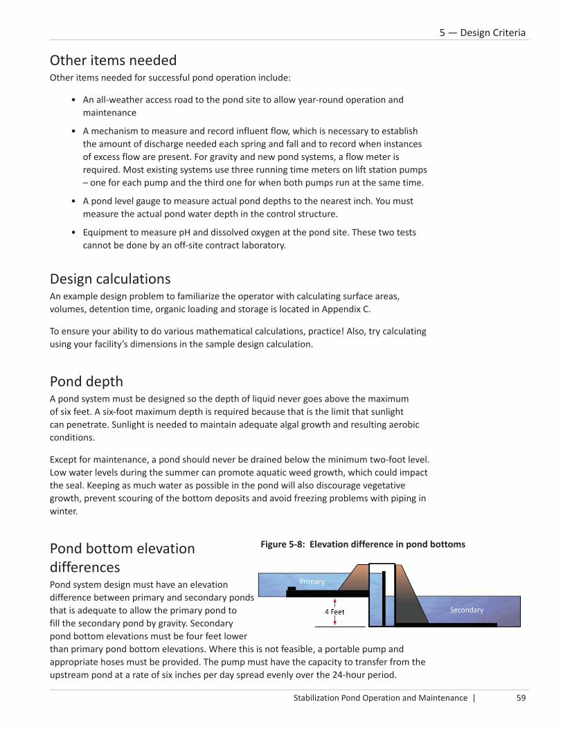
Stabilization Pond Operation and Maintenance | 59
5 — Design Criteria
Other items neededOther items needed for successful pond operation include:
• An all-weather access road to the pond site to allow year-round operation and maintenance
• A mechanism to measure and record influent flow, which is necessary to establish the amount of discharge needed each spring and fall and to record when instances of excess flow are present. For gravity and new pond systems, a flow meter is required. Most existing systems use three running time meters on lift station pumps – one for each pump and the third one for when both pumps run at the same time.
• A pond level gauge to measure actual pond depths to the nearest inch. You must measure the actual pond water depth in the control structure.
• Equipment to measure pH and dissolved oxygen at the pond site. These two tests cannot be done by an off-site contract laboratory.
Design calculationsAn example design problem to familiarize the operator with calculating surface areas, volumes, detention time, organic loading and storage is located in Appendix C.
To ensure your ability to do various mathematical calculations, practice! Also, try calculating using your facility’s dimensions in the sample design calculation.
Pond depthA pond system must be designed so the depth of liquid never goes above the maximum of six feet. A six-foot maximum depth is required because that is the limit that sunlight can penetrate. Sunlight is needed to maintain adequate algal growth and resulting aerobic conditions.
Except for maintenance, a pond should never be drained below the minimum two-foot level. Low water levels during the summer can promote aquatic weed growth, which could impact the seal. Keeping as much water as possible in the pond will also discourage vegetative growth, prevent scouring of the bottom deposits and avoid freezing problems with piping in winter.
Pond bottom elevation differencesPond system design must have an elevation difference between primary and secondary ponds that is adequate to allow the primary pond to fill the secondary pond by gravity. Secondary pond bottom elevations must be four feet lower than primary pond bottom elevations. Where this is not feasible, a portable pump and appropriate hoses must be provided. The pump must have the capacity to transfer from the upstream pond at a rate of six inches per day spread evenly over the 24-hour period.
Figure 5-8: Elevation difference in pond bottoms

60 | ©2013 Minnesota Pollution Control Agency All rights reserved.
5 — Design Criteria

Stabilization Pond Operation and Maintenance | 61
6 — Stabilization Pond Operation
6Stabilization Pond Operation
Theory of operation .............................................................. 63
Reducing CBOD, TSS and fecal coliform ................................ 65
Operational strategy ............................................................. 66
Proper pond operation ......................................................... 67
Control structures ................................................................. 70
Visual observations and the dissolved oxygen test .............. 73
Pond operation vs. chemical use .......................................... 74

62 | ©2013 Minnesota Pollution Control Agency All rights reserved.
6 — Stabilization Pond Operation
Stabilization Pond Operation and Maintenance | 63
6 — Stabilization Pond Operation
Chapter 6 – Stabilization Pond OperationThe National Pollutant Discharge Elimination System (NPDES) permit states:
“The Permittee shall at all times, properly operate and maintain the facilities and systems of treatment and control, and the appurtenances related to them which are installed or used by the Permittee to achieve compliance with the conditions of the permit. Proper operation and maintenance includes effective performance, adequate funding, adequate operator staffing and training, and adequate laboratory and process controls, including appropriate quality assurance procedures.”
A properly designed and operated controlled discharge stabilization pond system with 180 or 210-day minimum storage designed for the typical Minnesota climate should provide the operator with the necessary tools to produce an effluent (with the exception of total phosphorus and ammonia nitrogen) that will meet your NPDES effluent limits.
A stabilization pond system operator must manage and operate the pond system in a way that produces an effluent that meets the facility’s specific NPDES permit limits. Sometimes, because of design limitations, excessive influent loading, or issues within the collection system (mainly excessive inflow and infiltration), this may not always be possible. In that case, the system owner should hire a consultant engineer to determine what can be done to correct the problem(s).
Theory of operationTo operate a stabilization pond system correctly, the operator must understand the basic principle that relates to all biological treatment units. The basic principal is that all biological treatment systems require the following four items:
• A home (the pond system)
• Microorganisms (sometimes referred to as bugs or critters)
• Food (organic waste contained in the influent)
• Dissolved oxygen (produced by aeration or algae)
Microorganisms make their home in the pond system. They use oxygen dissolved in the water as they feed on and decompose organic waste entering the ponds. As organic waste is decomposed and solids settle to the bottom, the water becomes treated. Eventually, with proper water level control, the water is treated enough to discharge in the spring and fall to a nearby surface water body or irrigated during the summer.
Home + Microorganisms + Food + Oxygen = Clean water + Stable byproduct (biosolids)

64 | ©2013 Minnesota Pollution Control Agency All rights reserved.
6 — Stabilization Pond Operation
If any of these – home, microorganisms, food or oxygen – is absent, a biological treatment system will not perform properly and the operator will have a difficult time producing an effluent that meets NPDES permit limits.
Home (stabilization pond system)Home is the water within the stabilization pond system in which the food and microorganisms mix, for the most part, in an environment of dissolved oxygen. Constructing a pond system following specific design criteria will provide enough capacity and detention time to allow the reactions to occur and allow for discharge at the proper times. Most of the influent waste decomposes and settles in the primary pond(s). The secondary pond provides additional water clarification, fecal coliform reduction, and storage in preparation for discharge.
MicroorganismsThe microorganisms (bugs or critters) that decompose the organic waste in pond systems are the same as those found in many secondary biological wastewater treatment units with long detention times. Normally, incoming wastewater contains enough bugs to promote treatment. Only in very rare cases, possibly associated with certain high strength wastes, will an operator need to add microorganisms or nutrients to develop an active biological mass. This would only be a short-term solution. In that situation, you would likely add more aeration capacity.
Food (organic matter)Stabilization pond systems are designed for an organic (food) loading rate of 22 pounds CBOD/acre/day (or approximately 100 people/acre) of primary pond surface area. The influent normally supplies all the food (organic matter) the microorganisms need to support their life process. Microorganisms convert the food to a product that settles.
Dissolved oxygenWhen a pond system is functioning properly, algae and wind action supply enough dissolved oxygen (DO) for aerobic organism activity during spring, summer and fall. By operating and maintaining the system properly, the operator ensures that a good community of algae exists.
As shown in Figure 6-1, the amount of DO that water can hold (saturation level) is directly related to the temperature of the water. As the temperature of the water rises (becomes warmer), its ability to hold dissolved oxygen lowers. At sea level, 0°C (32°F) water can hold 14.6 mg/L of DO; at 20°C (68°F), water can hold only about 9.2 mg/L of DO.
Figure 6-1: Dissolved oxygen concentrations vs. temperature

Stabilization Pond Operation and Maintenance | 65
6 — Stabilization Pond Operation
Even though warmer water holds less oxygen, it supports algal growth. More algae (aided by sunlight) keep oxygen readily available. However, if an excessive amount of algae is discharged, it will eventually die and cause the DO levels in the receiving waters to drop to very low levels.
Reducing CBOD, TSS and fecal coliformIn a properly designed and operated stabilization pond system that is receiving an organic load within design conditions, biological oxygen demand (CBOD), total suspended solids (TSS) and fecal coliform levels will decrease. To be successful, an operator must know how and why this happens and how to operate the system in summer and winter in a way that encourages reduction. General mechanisms for reducing CBOD, TSS and fecal coliform include:
• Bacterial action by microorganisms in the primary pond(s) uses up most of the organic demand
• Within a few days, settling removes the majority of the influent TSS in the primary pond(s)
• TSS, in the form of algae produced in the primary pond, is reduced in the primary pond, and further reduced in the secondary pond by dying off and by being eaten by zooplankton and daphnia. By slowly transferring the primary pond water to the secondary pond, you will avoid transferring excessive phosphorus from the sludge layer. The phosphorus acts as a nutrient to the algae and promotes its rapid and excessive growth. Keeping a slow transfer rate between the primary and secondary ponds prevents excessive phosphorus from the sludge layer from moving into the secondary pond. The phosphorus that promotes algal growth will not be available in the secondary pond, resulting in more die off. (A slow transfer is defined as six inches or less from the upstream pond.)
• Fecal coliform organisms are removed by die off in an unfavorable environment, ultraviolet light from sunlight, algae toxins and predation by other microorganisms.
Reduction in summerIn the summer, some of the CBOD entering a pond system remains suspended in the water and is decomposed by the interaction of the bacteria and algae in the primary pond(s) – i.e., symbiotic cycle. The CBOD portion that enters in the form of settleable solids sinks to the bottom of the pond and is decomposed in the anaerobic sludge layer. In the primary pond(s), most of the CBOD will be decomposed by aerobic and anaerobic bacteria and converted to more stable compounds (sludge) within 30-45 days. By the time water is slowly transferred to the secondary pond, most of the CBOD should have already decomposed in the primary pond(s).
Influent wastewater also contains TSS that settles within a few days in the primary pond(s) and then undergoes anaerobic decomposition in the sludge layer. The TSS load to the secondary pond consists mainly of algae and bottom sediment held in suspension within the
Figure 6-2: Daphnia

66 | ©2013 Minnesota Pollution Control Agency All rights reserved.
6 — Stabilization Pond Operation
pond. Since the TSS tends to accumulate in the bottom one and one-half feet of the pond, it is not subject to excessive mixing. To reduce the carry-over of TSS during transfer:
• Ensure the transfer-piping inlet is two feet above the bottom of the pond
• Avoid transferring water during excessive windy conditions
• Transfer at a slow rate of no more than six inches per day from the upstream pond
Properly transferring the water through a vertical intake at least two feet above the pond bottom should reduce the TSS load (particularly phosphorus within the sludge layer) to the secondary pond.
Natural die off, predation, algae toxins, and ultraviolet light from the sun normally reduce fecal coliform organisms. Although most fecal organisms are eliminated in the primary pond(s), water transferred to the secondary pond may contain enough to violate NPDES permit limits. Water that has been properly transferred to the secondary pond will appear visually clearer than the water in the primary. Direct sunlight can then penetrate more deeply into the water and almost totally destroy the fecal organisms.
In the summer and early fall, operators often receive assistance from macroscopic (visible) organisms living in the pond system. The most common one found in Minnesota ponds is daphnia (water fleas). Daphnia, are between 0.2 and 5.0 millimeters long; they are filter feeders that consume algae and bacteria. As a result, they produce very clear water in a very short time. They are visible to the naked eye and are about the size and color of ground up pepper. Red streaks in the pond are Daphnia that turned red from being in a stressed condition. A stressed condition occurs when their food supply (algae) is diminished because of low DO levels. Figure 6-3 shows an example of daphnia under stress.
Reduction in winterIn winter, reduction of CBOD, TSS, phosphorus, and fecal coliform organisms is achieved differently because anaerobic decomposition is much slower in winter. Because of that, operators would typically operate primary ponds in parallel. By dividing the waste load equally between both primaries, more organisms will be available to reduce the waste load. In addition, incoming sludge spreads over two ponds, so the winter to spring transition from anaerobic to aerobic conditions should occur more quickly and with fewer odors.
Operational strategy: create old waterPond system design determines the flow pattern and how water levels are controlled in the pond system.
The operational strategy is all about controlling water levels in the pond system to create old water. Old water is water that has not had substantial amounts of raw wastewater (influent) added to or mixed with it. Depending upon whether
Figure 6-3: Daphnia under stress
Proper operational strategy is to create old water.
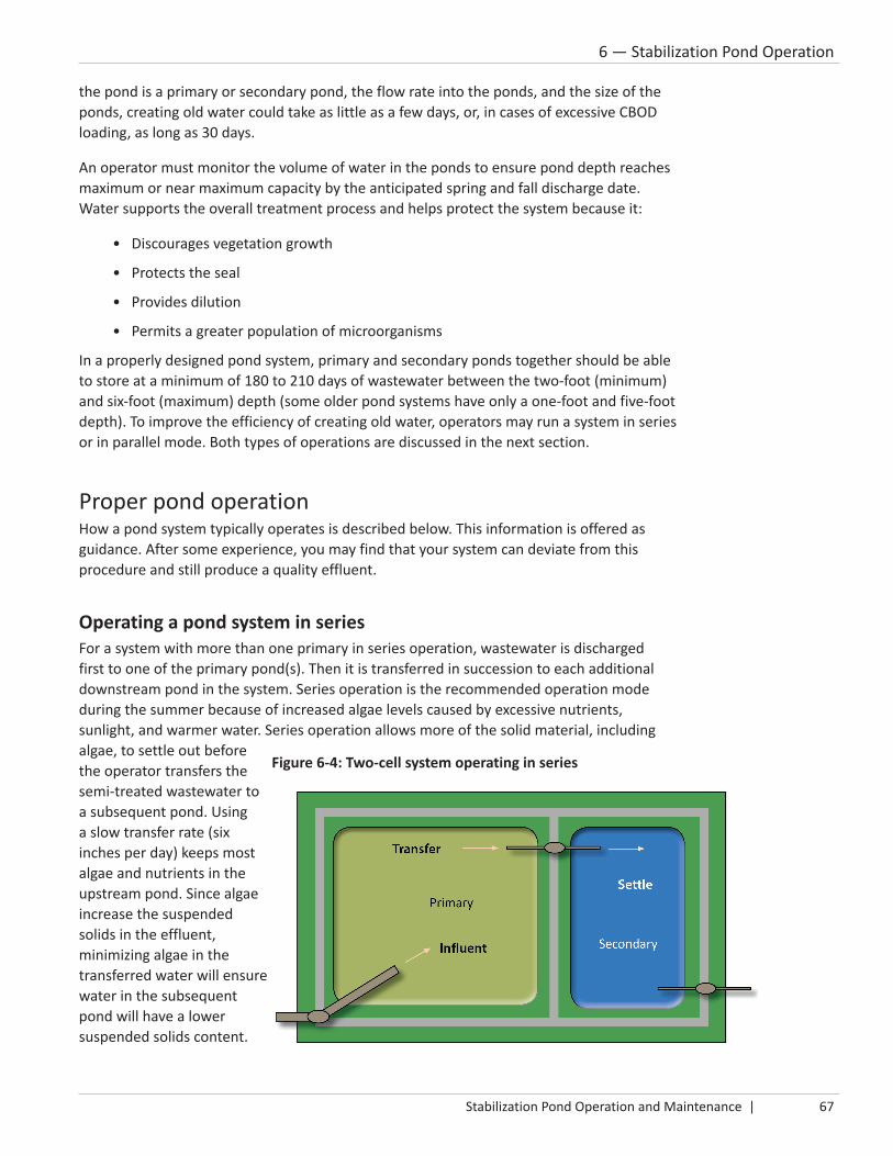
Stabilization Pond Operation and Maintenance | 67
6 — Stabilization Pond Operation
the pond is a primary or secondary pond, the flow rate into the ponds, and the size of the ponds, creating old water could take as little as a few days, or, in cases of excessive CBOD loading, as long as 30 days.
An operator must monitor the volume of water in the ponds to ensure pond depth reaches maximum or near maximum capacity by the anticipated spring and fall discharge date. Water supports the overall treatment process and helps protect the system because it:
• Discourages vegetation growth
• Protects the seal
• Provides dilution
• Permits a greater population of microorganisms
In a properly designed pond system, primary and secondary ponds together should be able to store at a minimum of 180 to 210 days of wastewater between the two-foot (minimum) and six-foot (maximum) depth (some older pond systems have only a one-foot and five-foot depth). To improve the efficiency of creating old water, operators may run a system in series or in parallel mode. Both types of operations are discussed in the next section.
Proper pond operationHow a pond system typically operates is described below. This information is offered as guidance. After some experience, you may find that your system can deviate from this procedure and still produce a quality effluent.
Operating a pond system in seriesFor a system with more than one primary in series operation, wastewater is discharged first to one of the primary pond(s). Then it is transferred in succession to each additional downstream pond in the system. Series operation is the recommended operation mode during the summer because of increased algae levels caused by excessive nutrients, sunlight, and warmer water. Series operation allows more of the solid material, including algae, to settle out before the operator transfers the semi-treated wastewater to a subsequent pond. Using a slow transfer rate (six inches per day) keeps most algae and nutrients in the upstream pond. Since algae increase the suspended solids in the effluent, minimizing algae in the transferred water will ensure water in the subsequent pond will have a lower suspended solids content.
Figure 6-4: Two-cell system operating in series

68 | ©2013 Minnesota Pollution Control Agency All rights reserved.
6 — Stabilization Pond Operation
Follow the procedures below to operate a two, three, four, or more ponds system in series.
To operate a two-pond system in series:
1. Shut off all control structures or valves, to prevent water from flowing between the primary and secondary pond. (The discharge structure must be closed.)
2. Create old water by holding it in the primary pond. When water depth in the primary pond is one foot more than the depth in the secondary pond, transfer six inches per day from the primary to secondary. (The discharge structure from the secondary pond must be closed.)
3. Continue to make old water and transfer six inches per day from the primary to secondary pond each time the primary is one foot deeper than the secondary.
To operate a system greater than two ponds in series:
1. Shut off all control structures or valves to prevent water from flowing between the primary and secondary ponds. (The discharge structure must be closed.)
2. Divert all influent flow into one of the primary ponds. (To avoid solids from building up, each year alternate influent flow between the primary ponds.)
3. When water in this primary is one foot deeper than the other primary(s), transfer six inches of water per day from one primary to the other primary.
4. Continue to make old water. When water depth in last primary is a foot more than the secondary pond, transfer six inches per day from last primary to the secondary. (The discharge structure must be closed.)
5. From then on, continue to make old water and transfer water each time the water in a pond is one foot deeper than the downstream pond.
Notes:
• When using series operation for three or more ponds, only transfer between two ponds at a time to reduce the potential for short-circuiting between ponds. Short-circuiting is when water bypasses the normal flow path and reaches the outlet in less than the normal detention time, not allowing time for sufficient treatment.
• A transfer rate of six inches per day (measured from the upstream pond) is recommended because it is slow enough to avoid transferring solids, particularly phosphorus, to the downstream pond. Excessive phosphorus will increase algae growth.
• Do not allow the secondary to remain at a depth of less than three feet for an extended period. Keeping the secondary at a depth of three feet or more will avoid excessive weed growth during the summer and freezing and damage to transfer piping in the winter.
Figure 6-5: Three-cell system operating in series

Stabilization Pond Operation and Maintenance | 69
6 — Stabilization Pond Operation
Operating a pond system in parallelTo operate in parallel, influent wastewater is discharged equally to all primary ponds by splitting the influent flow and loading equally. See Figure 6-6 and the procedure below. Parallel is the recommended operation type during winter because the overall pond system is usually anaerobic. Parallel operation distributes the solids and organic loading over a larger area, providing more treatment area when the pond is ice covered and biological activity is low. Distributing the CBOD loading helps avoid organic overload to one pond. (Note: a two-pond system cannot be operated in parallel.)
To operate a three-pond or larger system (two primary ponds and one secondary) in parallel:
1. Shut off all control structures or valves to prevent flow between all ponds. (The discharge structure must be closed.)
2. Equally, split influent flow and loading between all primary ponds.
3. Create old water by holding it in all the primary ponds. When water in a primary pond is one foot deeper than in the secondary pond, transfer six inches per day from that primary pond to the secondary.
4. After that, continue to make old water and then transfer water each time the water in a primary is one foot deeper than in the secondary.
Notes:
• A transfer rate of six inches per day is recommended because it is slow enough to avoid having solids, particularly phosphorus, transferred to the downstream pond. Excessive phosphorus will increase algae growth.
• Do not allow the secondary to remain at a depth less than three feet for an extended period of time. Keeping the secondary at a depth of three feet or more will avoid excessive weed growth during the summer and freezing and damage to transfer piping in the winter.
Transferring water between pondsWhen transferring water between ponds, follow these steps:
1. Create old water within each pond.
2. Transfer no more than six inches per day from the upstream pond.
3. As soon as possible, fill the secondary pond to a depth of at least three feet to avoid weed problems in the summer and freezing problems in the winter.
4. Isolate the secondary pond at least 30 days before the first discharge or irrigation. After that, you will need to isolate for only three to four days.
Figure 6-6: Three-cell system operating in parallel

70 | ©2013 Minnesota Pollution Control Agency All rights reserved.
6 — Stabilization Pond Operation
Elevation differenceA properly designed stabilization pond system should have at least a four-foot elevation difference between the primary and secondary ponds (Figure 6-7). With this elevation difference, a two-foot level in the primary corresponds to a six-foot level in the secondary. After discharging from the secondary pond, the elevation difference allows the operator to discharge the primary pond and refill the secondary pond to its maximum depth entirely by gravity.
When a pond system does not have an adequate elevation difference, the operator will need to use a portable pump to transfer water. As a guide, to pump six inches of water per day, you will need a 100 gallon-per-minute pump for every one acre of pond from which you are pumping. For example, if you need to transfer six inches of water from a six-acre pond, you
will need a 600 gallon-per-minute (gpm) pump (six acres times 100 gpm per acre).
When pumping, do not place the intake side of the piping near the bottom of the pond. Instead, use the control structure by pumping from one side of the divider wall to
the other. If that is not possible, use a floatation device to support the intake piping that is just below the pond surface.
After discharging four feet from the secondary pond, if additional discharge(s) are needed, the operator will use gravity or a pump to transfer water from the primary until the secondary pond depth reaches six feet. After filling the secondary, wait three or four days to allow time for the water to clarify before taking pre-discharge samples.
Control structuresOperators use control structures to regulate water levels to reach their goal of producing old water in order to produce a quality effluent that meets all NPDES permit requirements. Some control structures can be used not just to control the water level, but also to measure flow and water depth, sample, as an access point for pumping, and, when necessary, to add and mix chemicals.
Water level is controlled by adjusting slide gates, valves, or similar devices in the structure. Using slide gates or a telescoping valve allows the operator to pre-select the desired water depth.
Slide gate adjustmentsFigure 6-8 shows the correct adjustment of both slide gates in the control structure when water is not being transferred. The double slide gate system allows the operator to adjust the downstream gate without having to work against the head pressure of the upstream pond. The double slide gate system also provides better protection against leakage between the ponds. A valve on the downstream side provides additional assurance against leakage.
Figure 6-9 shows the downstream slide gate adjusted to a lower level. Then the upstream gate is raised to allow the ponds to be lowered to that level. When the ponds have reached
Figure 6-7: Elevation difference between ponds

Stabilization Pond Operation and Maintenance | 71
6 — Stabilization Pond Operation
the lower level, the operator lowers upstream slide gate and readjusts the downstream slide gate to the next lower level. Then the upstream slide gate is raised again to allow more water to transfer. The operator continues adjusting the gates until the ponds reach the desired level.
Note: If water pressure makes the upstream slide gate difficult to raise up, fill the area between the gates with water to equalize the pressure and allow for easier removal of the upstream slide gate. Also, grease or lubricate both slide gates guides to allow for easier removal.
Telescoping Valve Adjustment If your system has telescoping valves, you adjust the desired water level by the rotation of the mechanism from the outside of the control structure. The actual position (depth) of the telescoping valve is typically noted on the protruding valve stem.
Figure 6-8: Slide gate adjusted for no water transfer
Figure 6-9: Slide gate adjusted to allow water transfer

72 | ©2013 Minnesota Pollution Control Agency All rights reserved.
6 — Stabilization Pond Operation
Multiple uses for control structuresPumping between ponds should be accomplished by pumping over the splitter wall in a slide gate setup in the control structure. This will eliminate the need to place suction or discharge piping out into the pond. It will also eliminate possible erosion problems that may occur if the suction or discharge ends of the pipe were located on the dike slopes or at the pond bottom.
If you need to disinfect, you can use the control structure as a contact and mixing chamber, provided the detention time in the structure and outfall line is adequate.
Guidelines for controlling water levelsAn operator needs to be mindful of these general rules for controlling water levels in a stabilization pond system:
• To allow maximum time to clarify the transfer water, fill the secondary pond to maximum operating depth and isolate it as far ahead of the intended discharge as possible. A thirty-day isolation period is recommended before the first discharge. For subsequent discharges, only a three to four day isolation period is usually needed.
• The secondary pond is generally the first to deteriorate from excessive vegetation growth because it has the clearest water (allowing more sunlight to penetrate) and is usually the last pond to reach a three-foot water depth (adequate to discourage weed growth).
• Generally, operate a pond system in series during the summer and in parallel during the winter. However, pond systems with a very light organic (CBOD) load may get by operating only in a series mode – even during the winter.
• When operating two primary ponds in series, be careful not to organically overload the first pond. In pond systems with two primaries, both ponds together are designed to treat an organic loading of 22 lbs CBOD/acre/day (approximately 100 people per acre). However, when they are operated in series, the first pond will receive twice its designed organic loading. If overloading problems develop because of series operation, change to parallel operation.
• You may want to insulate control structures at the top to allow you to transfer water during the winter. Not insulating may allow the structures to freeze, causing significant problems when you try to transfer water.
• Do not allow water levels (especially in the secondary) to become less than three feet deep before an extended cold weather period to avoid damaging the seal or transfer piping.
• Do not transfer or discharge water during or directly after a period when the pond system has been drastically disturbed by strong winds.
• When transferring water to or from a pond, do not transfer faster than six inches per day (as measured from the upstream pond).
• Do not transfer water to a pond that is frozen or nearly frozen. The ice movement will break the inlet line.
During the summer, you will usually operate a pond system in series.

Stabilization Pond Operation and Maintenance | 73
6 — Stabilization Pond Operation
• When the elevation difference between primary and secondary ponds is less than four feet, you will need a pump capable of pumping six inches per day. The closer you are to design flow, the more important the need for a pump.
• Creating old water acceptable to discharge is the goal of proper stabilization pond operation. Creating old water is accomplished through controlling water levels in each of the ponds.
Visual observations and the dissolved oxygen testWhen operating a pond system, a trained operator may be able to determine the overall condition of the pond system by observing the water color, odors, vegetation growth and scum mats. These observations, along with results of a dissolved oxygen test, should provide enough information to estimate the overall condition of the pond system.
ColorThe color of pond water can indicate proper operation or a system imbalance. Many color variations may occur in a pond. Table 6-1 summarizes the most common cause of a color. However, the operator may need to observe the system more closely to determine the exact cause of the coloration.
OdorIn the early spring, immediately after the ice goes out, winter anaerobic conditions will produce a rotten egg odor due to the presence of hydrogen sulfide. When the pond switches from an anaerobic to an aerobic condition – a process that takes three to ten days – the odor should disappear. If the odor does not disappear, the primary pond has received too much of an organic load over the winter (possibly from a series operation or an excessive industrial load) or has an excessive amount of sludge accumulation.
In summer, a properly functioning pond system will have no odor or possibly a slightly musty odor. When odors do occur in summer, they are usually caused by organic overload, excessive sludge, or algae mats that are floating on the pond or washed up on the dikes.
Table 6-1: Common pond color
This color Often indicates
Dark green Normal primary pond operationLight green Normal secondary pond operation; indicates proper transfer
and reduced loadingDark Pea Soup Sometimes occurs in primary ponds during the summerBlack or Grey Normal right after ice out
If in summer, indicates organic overloading – too much CBODBlackish green Indicates presence of blue-green algaeRed streaks or pink
Red streaks are typically caused by daphnia under stress due to inadequate oxygen levels Pink could indicate presence of purple sulfur bacteria in anaerobic conditions or red algae in aerobic conditions

74 | ©2013 Minnesota Pollution Control Agency All rights reserved.
6 — Stabilization Pond Operation
Vegetation and floating matsProperly operating a stabilization pond requires the operator to minimize the vegetative growth or floating mats within the pond. Vegetative growth may cause operational problems such as short-circuiting (incomplete treatment), lack of mixing, improper distribution of influent load, insect breeding and, if the vegetation has deep roots, extensive seal damage.
The main problem with dense mats floating on a pond system is that they reduce the amount of sunlight that can enter the water column. Reduced sunlight limits algae activity, which, in turn, limits the amount of dissolved oxygen produced for use by the aerobic bacteria. Floating mats also limit the effects of wind action. Reduced wind action limits the mixing of pond contents and the amount of dissolved oxygen added through the mixing process. See the Maintenance chapter for more information on vegetation control and floating mats.
Dissolved oxygen testUse the dissolved oxygen meter to determine whether problems exist or are developing within the pond system. The operator must use a DO meter and take the readings directly in the pond from various locations. A normal active aerobic pond system should have a minimum of 1 to 2 mg/L of dissolved oxygen early in the morning. During the day, the dissolved oxygen concentration should be at least 5 mg/L or it may be supersaturated – above what the actual water can hold – at 14.6 mg/L or more, especially in cold weather.
If an operator observes odors, color changes, excessive mats, or vegetation, check the dissolved oxygen concentration to determine how it affects the system. Generally, dissolved oxygen should be, on an average, at least 5 mg/L.
Pond operation vs. chemical useChemicals such as alum (aluminum sulfate), ferric chloride, potassium permanganate, Hydrothol 191, or sodium percarbonate may be used to enhance the reduction of suspended solids or reduce effluent phosphorus levels. Due to toxicity concerns to sensitive receiving waters, using copper sulfate as an algaecide is not recommended. If you use copper sulfate, you must comply with the copper limits for the effluent and receiving water. All chemical doses should carefully follow manufacturer’s recommendations, including proper holding time before discharging. Call your MPCA regional compliance staff if you are thinking about using any chemical. You must report any use of chemicals on your supplemental report form.
Chemicals to reduce CBOD Chemical suppliers advertise agents, such as enzymes, to enhance biological activity, thereby reducing CBOD and improving pond efficiency or reducing overall sludge depth. In a pond system that is not organically overloaded and is operated and maintained properly, there is no measurable advantage to using enzymes. Even when a pond is organically overloaded,
Odors? Color changes? Excessive mats or vegetation? Test for dissolved oxygen!

Stabilization Pond Operation and Maintenance | 75
6 — Stabilization Pond Operation
purchasing enough enzymes to reduce CBOD adequately would be prohibitively expensive. If a pond is organically overloaded:
1. Determine the cause of overloading
2. Eliminate the cause at the source by working with the discharger to reduce discharges or pre-treat
3. Switch to parallel operation, if possible
4. Inform responsible city officials and contact your MPCA regional compliance staff for assistance, if needed
Chemicals used to reduce phosphorus Most pond systems use alum (aluminum sulfate) to reduce their total phosphorus concentration before discharging in order to comply with a NPDES permit limit for phosphorus. Some pond systems use ferric chloride or ferrous sulfate for the same purpose. Based on a survey done in 2011 of pond facilities using a chemical to reduce total phosphorus, it will require approximately 100 gallons of liquid alum per million gallons of water in the pond to reduce the total phosphorus level from 5 mg/L to less than 1 mg/L. To disperse the chemical, operators use either a small fishing boat (for a small pond system) or a pontoon boat (for larger systems). The chemical is injected into the water near the outboard motor propeller from a pump and a storage tank located on a boat . Both alum and ferric compounds require mixing to be effective. A majority of these pond systems have been very successful in reducing the total phosphorus to below 1.0 mg/L. The overall average has been 0.65 mg/L. Since every pond system will have different characteristics, ask your chemical provider to calculate the actual chemical usage for your system.
Chemicals used to reduce TSS The operator, through proper water level control, proper water transfer procedures, and discharging at the proper time will normally not have a problem with high TSS in the effluent. When the effluent of a pond has high TSS levels, it is normally because of a high algae population. A high algae population is caused by excessive phosphorus within the influent, the sludge layer or both. With a majority of Minnesota pond systems approaching 30 years of active use, an evaluation may be needed in the future to determine whether it is feasible to remove the sludge from, at least, the primary pond(s).
A common chemical used for algae control in lakes is copper sulfate or other chemicals containing copper. However, many questions related to using copper compounds in a pond system are still unanswered. The potential problems, plus the difficulty of proper application, require a much closer evaluation. Copper sulfate is not a
Figure 6-10: Applying chemicals in a pond

76 | ©2013 Minnesota Pollution Control Agency All rights reserved.
6 — Stabilization Pond Operation
quick, easy answer to algae control in a pond system. It is recommended that operators do not use copper sulfate (or other products that contain copper). A discharge after applying a copper compound would have to meet both the effluent limit and receiving water limit for copper. To discuss the copper limit in the effluent and receiving water, contact your MPCA regional complaince staff person (see Appendix H).
Other products that have been used are barley straw, Hydrothol 191, potassium permanganate, and sodium percarbonate. Use caution in choosing any product to avoid problems within the receiving waters; follow manufacturers’ recommendations.
• Barley straw releases a toxin that inhibits the actual growth of algae. Therefore, if barley straw is used, it must be in the pond system before any algae development. A large pond system may require a large amount of barley straw, so it may not be a feasible solution. The straw must also be removed from the pond before a fall discharge. Some operators will place the barley straw in netting or plastic snow fencing for easy removal. Use of 225 to 250 pounds of barley straw per surface acre is generally needed to keep the TSS concentration at lower levels
• Hydrothol 191 is an approved aquatic algaecide and herbicide. It is available in either a granular or liquid form. For it to be effective, you must use concentrations of at least 1.0 mg/L to reduce TSS levels below 45 mg/L. Also, the water temperature must be at least 68oF and aerobic. Because it is toxic at concentrations of 0.3 mg/L, you must wait at least four days before discharging the water or seven days before using the water for irrigation. This product is usually distributed over the pond surface by using a boat.
• Potassium permanganate is typically used in water treatment for taste or odor control. A normal dosage of 70 to 165 pounds per acre is needed to reduce the TSS concentration by one-half. When used, the water becomes a pink/purple color; the chemical stains your hands. Eye protection is needed as a safety measure. It can also be toxic to aquatic life. Like chlorine, it is a strong oxidizer; it is very volatile when it comes in contact with a volatile organic compound or petroleum product.
• Sodium percarbonate is an ingredient used in home and laundry cleaning products. It breaks down to hydrogen peroxide, sodium carbonate and soda ash. It is a granular, white crystalline powder and is water soluble. It comes in 50-pound bags that need to be mixed in the water. To treat light algae growth, you will need to use between three and 17 pounds per acre-foot of water. To treat heavy growth, use 30 to 150 pounds per acre-foot of water.
Figure 6-11: Algae in a pond

Stabilization Pond Operation and Maintenance | 77
6 — Stabilization Pond Operation
Chemicals used to reduce fecal coliformProperly operated and maintained pond systems should not need disinfection. If fecal coliform test results are above NPDES permit limits, it is usually caused by improper sampling techniques (i.e., taking a fecal sample in a non-sterilized container) or by a large population of birds. You cannot pour a sample from a can or bottle into a sterilized fecal coliform container. The sample must be taken in the sterilized container. It is a good idea to verify results with additional fecal coliform samples before you invest time, effort and expense trying to treat the fecal coliform.
However, if you must disinfect, there are two methods to disinfect a pond effluent with chlorine. Be aware that neither of these two methods has been used much in Minnesota pond systems.
1. Batch treatment of the secondary ponds with calcium or sodium hypochlorite Using this method requires the operator to distribute calcium or sodium hypochlorite over the entire area of the secondary ponds. By proper dosage and even distribution, this method can effectively reduce fecal coliform organisms. However, calcium hypochlorite usually is not used because of its cost and hazardous (explosive) nature.
The disadvantage of using sodium hypochlorite is that it is more expensive than liquid chlorine. Batch treatment with sodium hypochlorite normally is used when the control structure and outfall line does not provide adequate contact time of at least 30 minutes.
2. Chlorination of the effluent leaving the pond Chlorination of an actual discharge requires adding high-test hypochlorite (HTH) to the effluent as it leaves the pond. HTH can be contained in a sack or dissolved to a liquid and added at a well-mixed point (for example, where the water flows over the slide gate in the control structure). Also, there must be a minimum of 30 minutes detention time in the control structure and outfall line for the chlorine to adequately disinfect.
Dechlorination of the effluentBecause both methods of disinfection (added to the entire pond and of the effluent as it is leaving the secondary pond) have advantages and disadvantages, the operator should determine the best method for their system. Whichever method is used, it is extremely important that the proper amount of chlorine is used to disinfect without leaving a high chlorine residual in the effluent that may adversely affect the organisms within the receiving waters. If using chloride, you must meet the NPDES permit limit for chloride residual – 0.038 mg/L – during the discharge. To do that, you would have the following two options:
1. Use a dechlorination chemical such as sulfur dioxide (a gas), sodium metabisulfate (a solution), or sodium bisulfate (a solution)
2. Allow the chlorine to dissipate over time within the secondary pond. You will have to take chlorine residual samples to find when the result is less than 0.038 mg/L. Once it reaches that level, you will be able to discharge. However, monitoring of chlorine residual will have to be done, along with all the other required NPDES monitoring.
Properly operated and maintained pond systems should not need disinfection.

78 | ©2013 Minnesota Pollution Control Agency All rights reserved.
6 — Stabilization Pond Operation
If you believe you need to do any disinfection and dechlorination processes, call your MPCA regional compliance staff for assistance.
Chemicals for odor controlPond systems, when properly operated and loaded, will normally experience odor problems only for about three to 10 days during the spring thaw. The spring odors are associated with the natural biological changes in the pond: the change from winter anaerobic conditions to summer aerobic conditions. Unless the pond system is organically overloaded – the CBOD is
too high – most pond systems normally will not need chemical treatment for odors. Instead, if possible, switch to parallel operation. If that fails, then consider using chemicals. However, the best long-term solution is to eliminate the source of the organic overload.
Masking agents or perfumes have been used for odors in pond systems for a short-term solution. If a pond system experiences continuous odor problems, the answer is not a masking agent or perfume, but an in-depth evaluation of the source of the problem to determine the proper long-term solution.
When odors have to be eliminated, one of two chemical methods can be used to reduce their effect:
1. Hydrogen peroxide has been used to control hydrogen sulfide odors in pond systems. The proper application procedure requires that hydrogen peroxide be broadcast evenly over the pond surface so that the entire water volume is treated. The chemical reaction, in theory, requires 1 mg/L of hydrogen peroxide for 1 mg/L of hydrogen sulfide. If the hydrogen peroxide is properly applied, the reaction is very fast and results are noticed within minutes.
2. Sodium nitrate can be added to reduce hydrogen sulfide odors. To treat a pond system with nitrate, the salts must be dissolved in water and then dispersed into the pond water either by adding it to the influent (for a small pond) or by applying the solution on the surface with a boat (for larger ponds). The amount of nitrates to use and the frequency of application must be carefully calculated for each situation. Approximately 100 pounds of sodium nitrate per acre can be added the first day. If odor persists, add 50 pounds per acre per day after that. Adding nitrates does not add DO to the pond water, but encourages forming a population of nitrate-reducing bacteria. These bacteria will break down the waste using the nitrate compounds as an oxygen source rather than the sulfate compounds, resulting in nitrogen gases rather than hydrogen gases being produced. After adding nitrates, it takes a few days (depending upon temperature) to notice results because time is required for the colony of nitrate-reducing bacteria to develop. Adding nitrate salts will result in a longer period of reduced odor than by using hydrogen peroxide.
Odor may also occur because of large organic shock loads. In this case, temporarily resting the troubled pond by diverting the raw wastewater to an alternate pond should shorten the period of odors.
Properly operated and maintained pond systems should only smell for three to 10 days during spring thaw.

Stabilization Pond Operation and Maintenance | 79
6 — Stabilization Pond Operation
Odors may also develop from decaying vegetation, sludge, and blue-green algae mats. When these problems develop, good housekeeping practices, which include removing or breaking up the mats or vegetation, should solve the problem.
Figure 6-12: Floating mats on a pond

80 | ©2013 Minnesota Pollution Control Agency All rights reserved.
6 — Stabilization Pond Operation

Stabilization Pond Operation and Maintenance | 81
7 — Discharging Stabilization Ponds
7Discharging Stabilization Ponds
Acceptable and problem discharge periods ......................... 83
Dilution ratio determination................................................. 84
Discharge procedure ............................................................ 85
TSS and pH problems ............................................................ 91
Receiving water sampling ..................................................... 92
Spray irrigation operation and management ....................... 93

82 | ©2013 Minnesota Pollution Control Agency All rights reserved.
7 — Discharging Stabilization Ponds

Stabilization Pond Operation and Maintenance | 83
7 — Discharging Stabilization Ponds
Chapter 7 — Discharging stabilization pondsA stabilization pond discharge is the intentional or unintentional release of effluent from a stabilization pond system to the receiving waters. The operator must plan to discharge enough effluent to provide adequate storage capacity for the influent wastewater the system will receive during the next holding period, which is normally 180-210 days. Stabilization ponds that are properly designed will be discharged up to three times each during both the spring and fall discharge windows.
Excessive discharges that result in low water levels over a period may cause maintenance problems. Therefore, it is very important to discharge only enough to provide the needed storage capacity. Because the amount of influent flow and precipitation varies, the amount of water to be discharged may change from one year to the next. The number of discharges may also vary. An operator may find that no discharge is necessary or that the secondary pond must be filled and discharged many times to gain enough storage capacity. Allow adequate time to complete the necessary discharge(s). Appendix D will help you determine the total time you will need to complete each discharge; Appendix E will help you determine how much to discharge.
Acceptable and problem discharge periodsStabilization ponds are intended to be discharged when receiving waters are free of ice and the water temperature is warm enough to minimize oxygen depletion in the receiving water. In Minnesota, such favorable conditions generally occur during the spring and fall although each of the state’s nine major drainage basins exhibit individual hydrologic characteristics.
Tables 7-1 and 7-2 identify acceptable and problem discharge periods for the different areas in Minnesota to help you manage stabilization pond system discharges. Note that acceptable discharge periods for the northern regions of the state are longer than those for the southern regions to allow all discharges to be completed while receiving waters are free of ice cover.
An acceptable discharge period is not the same as a discharge window. An acceptable discharge period is defined by fixed dates in your permit. A discharge window occurs when discharge sample results should be able to meet NPDES permit limits. A discharge window is weather dependant and will change from year-to-year, and should occur within an acceptable discharge period.
Table 7-1: Acceptable discharge periods
MPCA Brainerd, Detroit Lakes, and Duluth OfficesSpring March 1 – June 30Fall September 1 – December 31
MPCA Rochester, Marshall, Mankato, Willmar, and Metropolitan (St. Paul) Offices
Spring March 1 – June 15Fall September 15 – December 31
Table 7-2: Problem discharge periods
MPCA Brainerd, Detroit Lakes, and Duluth OfficesSummer July 1 – August 31Winter January 1 – February 28 (29)
MPCA Rochester, Marshall, Mankato, Willmar, and Metropolitan (St. Paul) Offices
Summer June 16 – September 14Winter January 1 – February 28 (29)

84 | ©2013 Minnesota Pollution Control Agency All rights reserved.
7 — Discharging Stabilization Ponds
Acceptable discharge periods in Minnesota were revised July, 2009. Depending on the date of your permit, it may not reflect the revised discharge periods listed in Tables 1 and 2. As permits expire, they will be modified to reflect the revised dates. Until your facility’s permit is modified, follow the dates listed in your permit. If acceptable discharge period dates in your permit are not the same as the dates in this manual and you want to follow the new acceptable discharge periods, contact the MPCA regional compliance staff person assigned to your facility.
If your facility is covered by the Minnesota River Basin General Phosphorus Permit, you must use the dates listed in that permit; no discharge is allowed during June, July, August and September.
Avoid discharging when receiving waters are ice covered. Ice covered means 100 percent ice coverage from bank to bank, regardless of ice thickness. Discharging at this time has a high environmental impact because the ice cover slows the re-aeration of the water column in the receiving water. Even though a stretch of open water may be available at or near the discharge point, you must also consider the situation up to at least 15 miles downstream of the discharge because of the long decay rates of oxygen-demanding compounds in ice-covered receiving waters. Before ever discharging to ice-covered receiving water, you must contact and discuss the situation with your MPCA regional compliance staff and complete a Discharge Evaluation Report (see Appendix F).
During problem discharge periods and whenever receiving water is 100 percent ice covered, enough dilution must be available to protect the receiving water from excessive oxygen depletion. Should it become necessary to discharge in summer during the problem discharge period, the receiving water must be flowing fast enough to absorb the oxygen demand of the discharge. Table 7-3 is a guide to determine the required amount of dilution needed. A worksheet that will calculate the actual dilution ratio is included in Appendix G. If there is not an adequate amount of dilution, you must also sample the receiving water. You will need to discuss requirements with your MPCA regional compliance staff (see Appendix H).
Dilution ratio determinationIf you must discharge during a problem discharge period, you will need to calculate the amount of dilution necessary in relation to the pre-discharge CBOD5 concentration according to Table 7-3. See the Dilution Ratio Worksheet in Appendix G to calculate the dilution ratio.
Note: To calculate a dilution ratio, both receiving water flow rates and discharge flow rates must be expressed in units of cubic feet per second (cfs). To convert million gallons per day (MGD) to cubic feet per second (cfs), multiply the effluent flow expressed in MGD by 1.547. Example: A flow rate of 0.5 MGD is 0.5 MGD times 1.547 or 0.77 cfs.
Table 7-3: Dilution ratio determinationPre-discharge CBOD5 Concentration (mg/L)
Minimum Dilution Ratio (receiving water flow rate divided by discharge flow rate)
CBOD5 less than 5 mg/L No minimum dilution ratio necessaryCBOD5 5 to 10 mg/L 3 : 1CBOD5 10 to 15 mg/L 5 : 1CBOD5 15 to 20 mg/L 7 : 1CBOD5 20 to 25 mg/L 10 : 1More than 25 mg/L Call your MPCA regional compliance staff

Stabilization Pond Operation and Maintenance | 85
7 — Discharging Stabilization Ponds
Discharge procedureWhen discharging wastewater stabilization ponds to a receiving water, you will follow these basic steps, which are later described in detail (spray irrigation systems are not required to follow this procedure):
1. Determine whether a discharge is necessary. If it is, calculate the amount of water that must be discharged using the Discharge Calculation Worksheet found in Appendix E.
2. Plan so you have ample time to complete the necessary number of discharges within the acceptable discharge period.
3. No more than two weeks before you plan to begin the first discharge, collect representative samples from the secondary pond (If more discharges are required, the second and subsequent discharges will require about four days after transferring before taking pre-discharge samples).
4. If required, notify the MPCA regional compliance staff of your intent to discharge.
5. Discharge the amount (or part of the amount) determined in Step 1 at the rate of six inches per day or less.
6. Collect samples twice per seven days of a discharge (once every 3 days).
7. If more discharges are required (as determined in Step 1), go back to Step 3.
8. Complete monthly Discharge Monitoring Report (DMR) and any other required sample data and reports; submit them to the MPCA as required in your permit.
1. Determine whether a discharge is necessary, along with how much to discharge.
First, determine whether a discharge is even necessary. Use the Discharge Calculation Worksheet in Appendix E to help you decide whether you need to discharge and, if you do, the total number of feet of water to discharge. Calculations are based on the storage time needed until the next spring or fall discharge window (180-210 days). Add extra days to ensure you have enough storage. Calculations assume that rainfall, evaporation and seepage all balance each other; however, this may not always be true. From calculations and previous experience, the operator must decide whether the calculated discharge amount will be sufficient or whether to discharge a little more or less than the calculated amount.
Discharge only the amount needed to provide the required storage capacity. Unnecessary discharging may increase costs, work and maintenance problems within the system.
Even if you don’t discharge, you still need to complete and submit a DMR, including sample data and any other required reports (see step 8).
Discharge at a rate of six inches or less per day.
Discharge only enough to provide storage capacity.

86 | ©2013 Minnesota Pollution Control Agency All rights reserved.
7 — Discharging Stabilization Ponds
2. Plan so you have ample time to complete the necessary discharge(s) during the acceptable discharge period.
Appendix D is a guide to help you determine how much time it typically takes to complete the necessary discharge(s). This table is based on the assumption that you can completely fill the secondary after each discharge. If you cannot do that, the time required to discharge will increase dramatically. To ensure you have the best possible effluent, you need to allow time to fill the secondary pond completely with old water and at least 30 days before the first discharge. After the first discharge and then refilling the secondary, you need to wait only three to four days before taking pre-discharge samples.
Your permit allows a discharge only during the spring and fall acceptable discharge periods. Because of low influent flow, some systems may only need to discharge once a year. When that is the case, a fall discharge is preferred, since algae die off is usually more predictable. This will make it easier to meet permit limits for total suspended solids (TSS).
Some fall weather can be unpredictable; if you will be doing a fall discharge that will not completed by November 15, you need to measure the receiving water flow by November 15 in case receiving waters are ice covered before you complete discharging. You will need to know the receiving water flow rate to calculate the dilution required.
3. No more than two weeks before you plan to begin a discharge, collect representative samples from the secondary pond.
Before any discharge, you must take representative samples to estimate the quality of the proposed pond effluent. Take the samples from an aerobic secondary pond no more than two weeks before you intend to discharge.
In the spring, sample the secondary pond after it has switched from the anaerobic (no dissolved oxygen) winter conditions to the aerobic (with dissolved oxygen) spring conditions. This typically happens about a week or so after the ice is out. A sign this has happened is that the pond color will be clear or light green rather than brown, gray or black and its dissolved oxygen content will be least 2 mg/L. In the fall, take samples after algae die off; this typically happens in colder water conditions.
Everyone must sample at least for the following before a discharge to determine whether the effluent complies with NPDES permit limits. However, check your permit because individual permits may have additional permit limits requiring you to sample for additional parameters, such as ammonia, chlorides or total dissolved solids, before discharging.
At a minimum, sample for:
• Carbonaceous Biochemical Oxygen Demand (CBOD)
• Total Suspended Solids (TSS)
• Fecal coliform
• Dissolved oxygen
• pH
• Total phosphorus

Stabilization Pond Operation and Maintenance | 87
7 — Discharging Stabilization Ponds
Remember, the maximum allowed time between taking a pre-discharge sample and the beginning of the discharge is two weeks.
For more details on sampling, see Chapter 9, Sampling and Lab Testing.
To get a representative sample for carbonaceous biochemical oxygen demand (CBOD), TSS, and total phosphorus, take a grab sample in equal portions from at least four different sides of the pond and then mix them together into a composite sample. For total phosphorus samples, pour a portion of the composite sample into a sample bottle designated for nutrients. That sample container must contain a nutrient preservative.
The fecal coliform sample is a single grab sample collected in a separate sterilized container near the outfall structure. You cannot use the same container as the one used for CBOD and TSS. The fecal coliform sample container must be sterile.
For dissolved oxygen and pH, take samples at the pond site within the 24-hour period before you begin discharging.
Collect all samples at least eight feet from the dike and one foot below the surface of the pond. Do not collect samples during or immediately after excessive wind action because the pond system will be stirred up, which may cause the sample to violate NPDES permit limits.
Refrigerate or pack the sample in ice at 39°F (4°C) and transport it to the laboratory. The laboratory must receive the samples within 48 hours of sampling.
4. If required, notify the MPCA of your intent to discharge.
If all the pre-discharge sample results meet permit limits, and you will be discharging only during an acceptable discharge period, and the receiving water will not be ice covered during any part of the discharge, you do not need to notify the MPCA regional compliance staff before you discharge.
However, you must notify the MPCA regional compliance staff before discharge if any of the following situations is true:
• One or more pre-discharge sample results do not meet permit limits
• Discharge of any amount occurs during a problem discharge period
• You anticipate the discharge may occur to ice-covered receiving water (regardless of whether the discharge occurs during an acceptable or problem discharge period)
Be prepared to give all relevant information, such as pre-discharge sample results and dilution ratio calculation.
See Figure 7-2 for discharges during a Problem Discharge Period to ice-free receiving waters. See Figure 7-3 for discharges to ice-covered receiving waters.
Remember — two week maximum between taking a pre-discharge sample and discharging!

88 | ©2013 Minnesota Pollution Control Agency All rights reserved.
7 — Discharging Stabilization Ponds
Determine receiving water
flow ratePre-discharge
samples meet limits
Resample; meets limits?
Corrective measures;
meets limits?
Discharge subject to enforcement
NO
NO
NO
YES
YES
YES
YES
Call MPCA regional office
Dilution ratio adequate?
Sample effluent & stream twice each
7-day discharge period
Sample effluent twice each 7-day discharge period
Fill out Discharge Evaluation Report
NO
YES YES YES YES
Figure 7-2: Emergency discharge to ice-free receiving waters during problem discharge period
Determine receiving water
flow rate*Pre-discharge
samples meet limits
Resample; meets limits?
Corrective measures;
meets limits?
Discharge subject to enforcement
NO
NO
NO
YES
YES
YES
YES
Call MPCA regional office
Dilution ratio adequate?
Sample effluent & stream twice each
7-day discharge period
Sample effluent twice each 7-day discharge period
Fill out Discharge Evaluation Report
NO
YES YES YES YES
*You must determine receiving water flow rate before the onset of ice cover.
Figure 7-3: Emergency discharge to ice-covered receiving waters during any discharge period
DischargePre-discharge samples meet
limits
Resample; meets limits?
Corrective measures;
meets limits?
NO
NO
NO
YES
YES
YES
YESCall MPCA regional office
Sample effluent twice each 7-day discharge period
YES
Figure 7-1: Discharge to ice-free receiving water during acceptable discharge period

Stabilization Pond Operation and Maintenance | 89
7 — Discharging Stabilization Ponds
5. Discharge six inches per day or less.
Discharge by adjusting the slide gates or valves in the outfall structure to keep the discharge within the permit limit of six inches per day. Never lower the ponds below the minimum operating depth of two feet (one foot in older pond systems).
During a discharge, if pond water quality changes because of circumstances like excess winds, or if the discharge causes adverse effects on the receiving stream, reduce or discontinue the discharge and contact your MPCA regional compliance staff for assistance.
If the discharge meets all NPDES permit effluent concentration limits, but it is impossible to complete needed discharges before the end of an acceptable discharge period, it may be preferable to exceed the usual six-inch-per-day discharge rate rather than discharge to an ice-covered or low dilution receiving water. With accelerated discharges, concerns include:
• Excessive scouring of the receiving water channel
• Re-suspension (and discharge) of solids
• Potential to damage the integrity of the pond’s liner
• Potential to flood downstream properties
• Exceeding the mass loading limits (in kilograms per day) in the NPDES permit
If you believe you need to discharge faster than six inches per day, call your MPCA regional compliance staff for assistance.
6. Collect samples during a discharge
When discharging, you must sample twice during a seven-day discharge period, taking one sample every three days. Take the samples from the final control structure during the discharge. The minimum tests are listed below. Your NPDES permit may require additional tests, such as nitrogen, chlorides, etc.
• Carbonaceous Biochemical Oxygen Demand (CBOD)
• Total Suspended Solids (TSS)
• Fecal Coliform (a separate sample taken in a sterilized container)
• Total phosphorus
• Dissolved oxygen (conducted on site immediately after sampling)
• pH (conducted on site immediately after sampling)
If you take samples more frequently than required, you must include the results in the calculations reported on the monthly supplemental report form.
7. Additional Discharging
If you determine additional discharging is necessary, first refill the secondary pond using the oldest water in the system. Before refilling the secondary, close the secondary pond effluent gate. Then use the slide gates or valves between the ponds to regulate the transfer flow. If the difference in elevation between the primary and secondary pond bottom is less
If you believe you need to discharge faster than six inches per day, call your MPCA regional compliance staff for assistance!

90 | ©2013 Minnesota Pollution Control Agency All rights reserved.
7 — Discharging Stabilization Ponds
than four feet, you will need a pump to completely refill the secondary. After refilling the secondary, allow three or four days for the pond to stabilize before taking another set of pre-discharge samples. Then repeat the procedures used for the initial phase of the discharge (see Steps 1 to 6).
After completing all necessary discharges, refill the secondary pond to at least three feet to prevent weed growth in summer or ice damage to the piping system in winter. Filling the secondary pond before freezing conditions prevents damaging pipes, which happens during a transfer to a frozen pond.
Calculating the discharge flow rate
The stabilization pond discharge flow rate calculation is based on the area of the discharging pond listed in your NPDES permit and the fraction of a foot of water discharged per day. To calculate discharge flow rate you will need to take accurate measurements of the drop in pond level during the discharge. The formula for calculating the discharge flow rate in million gallons per day (MGD) is:
For example, the volume of water discharged from a three-acre pond in which the water level drops six inches in one day is calculated as follows:
Drop in water level (in feet): 6 inches 1 foot = 0.5 feet/day day 12 inches
Flow rate = 0.5 feet 3 acres 0.326 million gallons = 0.489 MGD day acre-foot
Emergency discharges
Because of the high potential for adverse environmental impact, flow-through discharges are only allowed by the MPCA in an emergency when all other options have been exhausted.
Flow-through (continuous) discharge is achieved by allowing the pond system to discharge at the maximum design operating depths. The volume of influent wastewater forces an equal volume of water to discharge between ponds resulting in a discharge to the receiving water. Although allowed in certain emergency situations, a flow-through discharge is not desirable because it maximizes the probability of water quality problems.
A flow-through discharge would likely take place if one or more of these problems exist:
• A facility is forced to release water during a problem discharge period
• The facility cannot meet effluent limits
• An adequate dilution ratio is not available
• A combination of the above-listed problems exist
Flow Rate (in MGD) = depth discharged (fraction of foot per day) times pond area (acres) times 0.326 million gallons per acre-foot

Stabilization Pond Operation and Maintenance | 91
7 — Discharging Stabilization Ponds
Because the ponds are being operated at maximum operating depths, a flow-through discharge will likely continue for the duration of a problem discharge period. The quality of the discharge is likely to degrade over time, as relatively untreated (primary) wastewater mixes with treated (secondary) wastewater.
During a flow-through discharge, your NPDES permit requires that you sample the effluent twice in a seven-day discharge period. Sampling should be done three to four days apart. You will also need to monitor the receiving water by sampling twice in a seven-day period (three to four days apart) if any of these conditions are true:
• The flow-through discharge occurs during a problem discharge period
• The receiving water is ice covered
• An adequate dilution ratio is not available
When a flow-through discharge happens, complete and submit a Discharge Evaluation Report form to the MPCA with your DMR. A copy of the form is shown in Appendix F; it is available at http://www.pca.state.mn.us/f9ap8yx.
8. Complete a monthly Discharge Monitoring Report (DMR) along with required supplemental form(s) and submit all to MPCA by the 21st day of the following month.
Record results of all lab tests conducted during the discharge, along with influent and effluent flow on the monthly supplemental operation report forms. Enter totals for all values at the bottom of the supplemental report form. Keep results of pre-discharge sampling on file with your other records; you need not report them on your supplemental report form.
All DMR and supplemental form(s) must be submitted electronically by 11:59 p.m. of the 21st day of the following month. Record related factors that may have affected the discharge in the remarks section of the supplemental form. See http://www.pca.state.mn.us/hqzqb28.
TSS and pH problemsEven stabilization ponds that are properly operated and loaded within design parameters have experienced problems with elevated pH concentrations and algal blooms that cause effluent to exceed CBOD and TSS limits. Favorable growth conditions plus nutrients (nitrogen and phosphorus) in wastewater cause algal blooms in pond systems. The algal blooms, in turn, cause effluent TSS concentrations to rise. Algae does not go through the filter on the TSS analysis and therefore is counted as a total suspended solid.
When TSS concentrations are above 45 mg/L but below 65 mg/L, a discharge would violate permitted effluent limits. However, if you wait for the ponds to clear up, you may risk having to discharge in a problem discharge period or to an ice-covered receiving water. Neither situation is good; both would violate the NPDES permit violation and make you subject to MPCA enforcement action. However, a discharge with adequate receiving water flow and favorable re-aeration conditions usually has less environmental impact. If you are in this situation, discharging an effluent with elevated TSS may be the better of two options. Call your MPCA regional compliance staff to discuss the situation, your options and the sampling requirements for the receiving waters.
If a flow-through discharge happens, complete a Discharge Evaluation Report.

92 | ©2013 Minnesota Pollution Control Agency All rights reserved.
7 — Discharging Stabilization Ponds
Most pond wastewater systems in Minnesota are required to meet permit limits of between six and nine pH. During the day, algae consume carbon dioxide in the process of photosynthesis. As this happens, it lowers the carbonic acid concentration in the water column resulting in higher pH. At night, algal respiration produces carbon dioxide. The carbon dioxide dissolves in the water column as carbonic acid and the pH drops. If you have questions about pH that is outside of the limits, call your MPCA regional compliance staff.
Receiving water samplingDischarges to ice-covered or low-flow receiving waters may deplete dissolved oxygen levels and disrupt the aquatic habitat. To protect receiving waters during these conditions, you must ensure the dilution ratio is adequate. The dilution ratio is the proportion of receiving water flow rate to effluent flow rate. The dilution varies in proportion to the effluent’s oxygen demanding characteristics. Table 7-3 (page 84) shows the minimum dilution ratio needed based on effluent CBOD5 concentrations.
If pre-discharge or effluent samples indicate that effluent limits will be exceeded during a problem discharge period and an adequate dilution ratio is not available, take two samples of each of the following three to four days apart for each seven days of discharging:
• pH
• Fecal coliform bacteria
• Dissolved oxygen
• Total phosphorus
Dissolved oxygen (DO)You may be required to collect receiving water samples for DO:
1. Upstream of the discharge point to establish the background conditions of the receiving water
2. Downstream in the river reach likely to be impacted by discharges occurring during problem discharge periods
Other considerations when sampling for DO:
• During warm weather months, the DO impact zone is likely to be within one to three river miles downstream of the discharge point.
• The DO impact zone for a discharge to ice-covered receiving water is likely to be up to 15 river miles downstream of the discharge point.
• Collect open water DO samples during the early morning hours (within two hours after sunrise).
• Collect DO samples from ice-covered receiving waters at any time during the day.
• Analyze all DO samples immediately.

Stabilization Pond Operation and Maintenance | 93
7 — Discharging Stabilization Ponds
pHIf pre-discharge or effluent sample results indicate that pH will exceed effluent limits, collect pH samples upstream of the discharge point and one to three river miles downstream of the discharge point. Analyze all pH samples immediately. You will then need to call your MPCA regional compliance staff to discuss the discharge procedure.
Fecal coliformIf pre-discharge or effluent sample results indicate that fecal coliform bacteria will exceed effluent limits, collect fecal coliform bacteria samples upstream of the discharge point and one to three river miles downstream of the discharge point. Collect fecal coliform bacteria samples in sterilized containers as individual grab samples. Preserve them properly and deliver them to the laboratory for analysis within the specified holding time. You will then need to call your MPCA regional compliance staff to discuss the discharge procedure.
Total phosphorus (TP)If pre-discharge samples indicate that total phosphorus (TP) will exceed effluent limits, collect TP samples upstream and one to three river miles downstream of the discharge point. Take TP samples as individual grab samples in their own special container, preserve them correctly and deliver them to the laboratory for analysis within the minimum specified holding time. You will then need to call your MPCA regional compliance staff to discuss the discharge procedure.
Report all receiving water monitoring results to the MPCA on the supplemental report form for the month during which the discharge occurred. If you did not or were unable to obtain receiving water samples, specify why you did not collect samples.
Spray irrigation operation and managementThe operation and management of a spray irrigation pond system is identical to a stabilization pond system, except for how the treated wastewater is irrigated during the summer to provide adequate storage for the winter season. All spray irrigation systems are designed to provide storage for at least 210 days. In northern Minnesota, the storage period may even be longer.
Goals for spray irrigationGoals for spray irrigation and management are:
• Protecting the ground water
• Protecting the surface water from runoff
• Protecting the soil
• Protecting the cover crop
• Removing nutrients
Remember to analyze dissolved oxygen and pH samples immediately!

94 | ©2013 Minnesota Pollution Control Agency All rights reserved.
7 — Discharging Stabilization Ponds
Spray irrigation managementAn excessive amount of irrigation that has not been properly treated could contaminate the groundwater. Some facilities are required to install groundwater-monitoring wells around the irrigation system to determine the effect irrigation is having on the groundwater system.
No surface runoff or discharge is allowed to any receiving waters from the irrigation site. This includes both from irrigation and precipitation mixed with the irrigation water. A runoff collection system is required. You are required to maintain daily precipitation records.
The operator must control the irrigation rate to prevent saturation of the soil. The wastewater flow from the pond system shall not contain any physical or chemical characteristics that prevent the proper operation of the land disposal system. Irrigation is not allowed during periods of precipitation. No aerosol drift that creates a nuisance condition is allowed. You are required to control and abate aerosol drift.
The NPDES permit does not allow irrigation on the irrigation site when the cover crop is dormant (not actively growing) as a result of frost or below freezing temperatures. It is also not allowed on any cover crop used directly for human consumption. The cover crop is a very important part of the irrigation system. The main function of the cover crop is to take up and remove nutrients. It not only takes up and removes nutrients, but removes some of the water, improves and maintains soil infiltration, along with adding organic matter to the soil and possibly providing some
revenue when the cover crop is sold for feed for animals.
SamplingThe NPDES permit requires sampling of the water being irrigated along with what is coming into the treatment system. Groundwater sampling may also be required. Consult your permit for the sampling requirements.
Do not irrigate when the cover crop is dormant.

Stabilization Pond Operation and Maintenance | 95
8 — Maintenance
8MaintenanceReasons for maintenance ..................................................... 97
Necessary pond system maintenance .................................. 97
Vegetation ............................................................................ 98
Controlling specific plant types ............................................ 99
Grass cover on dike slopes ................................................. 100
Controlling erosion ............................................................. 101
Controlling rodents ............................................................. 102
Floating mats ...................................................................... 103
Control structures ............................................................... 105
Controlling mosquitoes and insects ................................... 105
Solids accumulation at the inlet pipe ................................. 105
Seepage loss ....................................................................... 106
Roads, signs, gates and fences ............................................ 107

96 | ©2013 Minnesota Pollution Control Agency All rights reserved.
8 — Maintenance

Stabilization Pond Operation and Maintenance | 97
8 — Maintenance
Chapter 8 — Maintenance
Reasons for maintenanceThe National Pollutant Discharge Elimination System (NPDES) permit states:
“The Permittee shall at all times, properly operate and maintain the facilities and systems of treatment and control, and the appurtenances related to them which are installed or used by the Permittee to achieve compliance with the conditions of the permit. Proper operation and maintenance includes effective performance, adequate funding, adequate operator staffing and training, and adequate laboratory and process controls, including appropriate quality assurance procedures.”
A stabilization pond system requires routine maintenance of dikes, control structures, and lift stations to ensure structural integrity and preservation of the facility. Although maintaining a pond system can become very labor intensive if not done regularly, maintenance is extremely important. If neglected, a pond system can deteriorate in a very short time, resulting in costly repairs and even reconstruction. Neglecting maintenance will result in NPDES permit violations.
Proper maintenance is needed to:
• Protect the seal
• Reduce odor and insect problems
• Prevent short-circuiting
• Increase sunlight penetration
Necessary pond system maintenance Many areas require regular maintenance including:
• Controlling and removing vegetation – both submerged and floating (mats)
• Mowing grass
• Controlling erosion
• Controlling rodents
• Maintaining control structures
• Monitoring for seepage
• Maintaining entrance road, fences, gates and signs
Figure 8-1: Prevent erosion; maintain dikes!

98 | ©2013 Minnesota Pollution Control Agency All rights reserved.
8 — Maintenance
Vegetation
Using herbicidesAny herbicide used to control vegetation must be approved by the Department of Natural
Resources and the product registered with the Department of Agriculture. Before using an herbicide, you must identify the plant type so you know the correct herbicide to use and the proper time and method to apply it. Questions are often asked about the use of Roundup™, Rodeo™, and Reward™. Roundup™ can only be used in the riprap to eliminate excessive weed growth. Rodeo™ and Reward™ are approved aquatic herbicides for controlling weed growth within or near the water. The use of copper sulfate is not recommended. If you use copper sulfate, you must meet an effluent limit and a water quality limit for copper. This will require sampling during the discharge of both the pond and the receiving water. Before using copper sulfate, contact your MPCA regional compliance staff.
Vegetation concernsIt is necessary to control harmful vegetation growth in the dike system, near the water line, and within pond system. Shallow water areas at the water line encourage the growth of cattails, willows, cottonwoods, and similar plants. You may be able to remove small plants by pulling or cutting. In some cases, you will need to use approved herbicides.
Whatever type of vegetation control method you use, it is important to remove the plant material from the pond. If you leave it in the pond, it will decompose and increase the oxygen demand, add to the sludge layer at the bottom of the pond, create unsightly conditions and may reseed, making the problem worse.
You will need to ask yourself the following two questions concerning the growth of any vegetation:
1. Is it deep-rooted?
2. Has it affected the dissolved oxygen level in the pond (oxygen less than an average of 2 mg/L)?
If you answered yes to either of these questions, you must remove the vegetation immediately.
Promptly remove vegetation that is deep-rooted or affects dissolved oxygen!
Figure 8-2: Control vegetation

Stabilization Pond Operation and Maintenance | 99
8 — Maintenance
Types of vegetationConsider both floating and submerged vegetation:
• Floating – plants that grow to the surface create areas where scum, floating sludge, and other debris tend to congregate, eventually causing mats that block sunlight. Reduced sunlight reduces the amount of oxygen algae produce. The mats may cause odors and encourage insect breeding problems.
• Submerged – some plants have extensive and deep root systems that can penetrate the seal and cause seepage problems.
If pond water depth is not below three feet for an extended period during the summer, submerged vegetation should not be a problem. However, when the pond water level drops below three feet for an extended period of time, the operator should start regularly inspecting for plant growth that may start to develop. Typically, if the water level drops below the three-foot minimum in the primary pond, water is often turbid (murky) enough that the amount of sunlight reaching the pond bottom will be too little for plant growth. Of more concern is the secondary pond in which water will be considerably clearer. Therefore, carefully inspect the secondary pond – even when the minimum three feet of water is maintained – to ensure vegetation does not develop.
Dense stands of vegetation, both floating and submerged, may cause short-circuiting and incomplete treatment within the pond, and reduce wind action and mixing of the pond contents.
Keep vegetation in the ponds to a minimum to prevent it from:
• Destroying the pond seal
• Attracting burrowing animals
• Restricting wind action
• Harboring insects
Controlling specific plant types
CoontailCoontail is one type of submerged plant that has been shown to be beneficial. Coontail is not deep rooted. It has a main stem with branches that have needle-like leaves. The branches and needles look like a raccoon’s tail – hence the name. Coontail absorbs nutrients, and therefore limits the excessive growth of algae. Water will typically be very clear when coontail is present. Samples taken from a pond with coontail are usually low in BOD, TSS, and total phosphorus. It is generally best to leave it in the pond. Only when overall growth becomes very dense and interferes with sunlight penetration will you need to remove it.
Figure 8-3: Coontail

100 | ©2013 Minnesota Pollution Control Agency All rights reserved.
8 — Maintenance
CattailsCattails are the most troublesome deep-rooted plants found in Minnesota pond systems. Cattails easily become established in the shallow water along the dikes, or wherever the water level is below three feet for an extended period. Cattails’ extensive root system can damage the seal. They provide habitat for rodents, reduce circulation and cause short-circuiting. In addition, they may be aesthetically displeasing.
You can use several methods to control cattails; however, you must choose a removal method appropriate to the amount of plant growth and the time of year.
• Pulling Pull cattails early in their first year of growth when they are young and before they become established.
• Cutting and drowning Cut off the cattails as close to the bottom as possible. Immediately after cutting, drown them by raising the water level to at least three feet above the top of the cut cattails. If you cannot cut them close to the bottom, cut them at least three feet below the usual water level. Raising the water level to at least three feet will reduce the amount of sunlight that penetrates the water to the plants. This in turn will hinder the root system from continuing to grow. Cutting and drowning is most effective if done mid-June to mid-July when the cattail flowers are actively growing. Cattail flowers are developing when you see a dark green and pebbly textured flower on top of the stalk, with a pale green flower just below it.
• Spraying with an approved herbicide Use herbicides only as a last resort; however, if cattails are extensive and dense, using herbicides may be the only practical and effective way to eliminate them. Only use herbicides approved by the Minnesota Department of Natural Resources. Follow manufacturer’s application directions exactly. Most herbicides should not be applied until the plants are 18 inches above the water to ensure adequate leaf surface for chemical contact and allow the use of a wetting agent. Successful methods for spraying a pond include high-pressure spraying rigs mounted on dikes or fire trucks and portable spraying rigs mounted in boats. Although initial cost may be high, using the proper herbicide will likely result in increased savings in time and money overall.
Grass cover on dike slopesThe grass cover on dikes discourages erosion. Frequently mowing dike slopes is the best way to preserve the integrity of the dike system.
Appropriate grasses for use on inner dikes are fast growing, spreading and shallow rooted; however, dense types such as rye, brome, and quack are not acceptable. Use grass with long root structures, such as alfalfa or reed canary grass, only on the outer dikes. The roots of these
Using grazing animals, such as sheep, cows, and goats, as a substitute for mowing is not recommended because they will damage the dikes and make erosion problems worse.
Figure 8-4: Cattails

Stabilization Pond Operation and Maintenance | 101
8 — Maintenance
plants can alter the compaction of the inner dike and impair the water-holding capacity of the seal, eventually causing structural failure and costly repair.
When planting additional grass on the dike, use netting or mulch material to hold the grass seed and moisture while roots become established.
Mow the grass on the dikes at least monthly; twice a month is the recommended rate. Frequent cutting promotes a thicker strand of grass and allows the operator to observe developing problems on both sides of the dike slopes.
Controlling erosionThe NPDES permit requires that dikes be inspected weekly. Take special note of potentially weak areas along the dike and:
• Around control structures
• In the corners
• In areas where vegetative cover on the dike is inadequate
• In areas where dikes were not sufficiently compacted during construction
Because of increased wave action from wind traveling across the pond, erosion problems can be more serious on the downwind side of the pond. Therefore, inspect these areas more frequently.
Erosion problems greatly reduce the design life of a pond system. Erosion may:
• Wash away the liner cover material or possibly the actual liner
• Create difficult maintenance areas along the dikes
• Increase the potential for muskrat habitat and damage to the dikes
The most practical method of controlling erosion is using riprap material. Riprap, or some other acceptable method of erosion control, is required on all inner dike slopes for new pond systems. Before placing riprap on existing pond systems the first time, you must make sure the seal’s integrity is intact. Riprap material is placed from the toe of the dike to at least one foot above the high water line. A current design criterion recommends placing riprap all the way to the top of the dike.
The type of riprap you use depends upon what material is readily available. Riprap materials used for erosion control should include:
• Durable, clean rocks in assorted sizes, such as fieldstone or quarry (angular, crushed bedrock). Most rocks should be between two and nine inches in diameter and placed a minimum of six to 12 inches deep.
• Materials like snow fences or straw and hay bales may be used as a temporary measure in an emergency situation. They must be replaced by permanent riprap.
Figure 8-5: Riprap

102 | ©2013 Minnesota Pollution Control Agency All rights reserved.
8 — Maintenance
Materials that should not be used as riprap include:
• Asphalt material from streets – it would have to be replaced after a few years because freezing and thawing will break it up into small pieces and may leach toxic and oil materials into the water
• Rubble from demolished buildings and street improvement projects such as bricks or chunks of concrete sidewalks – they make excellent habitat for rodents to burrow into the dike
• Sandstone rock – over time it erodes easily
• Tires – they shift on the dike, rodents can get through them to burrow into the dike, they provide excellent breeding habitat for insects, and hazardous chemicals may leach off the tires into the pond
Controlling rodents One critical part of weekly dike inspections is to look for burrowing animals such as muskrats, badgers and gophers that can cause serious damage to the dike system.
Gophers and badgersGophers and badgers generally cause problems on the outside of the dikes. They are usually easy to detect because of the dirt mounds they make when they tunnel. Gopher and badgers cause two main problems:
1. Their dirt mounds make grass cutting and general dike maintenance difficult.
2. If their tunnels angle toward the inner dike, the possibility for the tunnel to connect with a muskrat tunnel and cause a leak greatly increases.
MuskratsMuskrats are the leading troublemakers for pond operators. They often can be eliminated simply by preventive maintenance. Since many types of vegetation are major food sources
for muskrats, controlling vegetation can help to get rid of them.
Muskrats make their homes by burrowing in dikes to provide an entrance to their den which is above the water line. Tunnels (runs) begin below the water line and penetrate the inner dike and liner/seal at an upward angle. A tunnel will end up in a dry chamber (den) above the water line. Because tunnel entrances are underwater, you will need to inspect carefully after a discharge or transfer of water to detect their presence.
Figure 8-6: Entrance to a muskrat den

Stabilization Pond Operation and Maintenance | 103
8 — Maintenance
If riprap is present, locating a muskrat run is difficult. Muskrats have been seen entering very small areas between the riprap. Operators may use several methods to find entrances to muskrat runs and muskrat dens:
• Observe where the muskrat swims to the dike; this is normally close to the tunnel entrance
• When the water level is very low, to help locate the tunnel entrance, look for muskrat tunnels below the water line
• If you have grass dikes, walk along the dike and look for any depressions in the dike; tunnels and dens are often shallow enough that you can find a depression
Discuss with your local Department of Natural Resources (DNR) Conservation Officer the best way to remove muskrats – shooting, trapping or poisoning. After eliminating the muskrats, carefully repair the damaged areas of the dike. Normally, repair requires removing the riprap and liner, digging open the tunnel, replacing the clay or vinyl liner that was removed, re-compacting the area, and then placing rip rap material at the closed tunnel entrance and den.
Floating matsFloating mats are common on a pond system in the late summer, especially in areas where there is very little wind action. Floating mats may consist of a combination of sludge, blue-green algae, grease and oil, and duckweed.Generally, if the dissolved oxygen content around the entire pond is above 5 mg/L, removal is not necessary.
Heavy mats may cause problems, such as:
• Reduced sunlight penetration, which lessens algae activity and lowers dissolved oxygen
• Odors
• Loss of aesthetics
• Creating insect breeding areas
Blue-green algaeAlthough blue-green algae could exist in ponds at all times during the summer, mats form mainly during August and early September. The presence of blue-green algae usually is associated with high organic loading, low dissolved oxygen, and warm water conditions. Mats can be poisonous to animals that drink the water. Rotting mats can cause odor problems.
Removal is usually not necessary. If it is, first try to break the mat up so it settles. If the pond containing blue-green algae is the first pond receiving the influent waste, diverting the influent to the other primary for a week or so may reduce the problem. Normally the blue-green mats will not occur if the ponds receive adequate mixing by the wind. As nights become cooler, the mats should dissipate naturally.
Heavy floating mats may cause problems!

104 | ©2013 Minnesota Pollution Control Agency All rights reserved.
8 — Maintenance
Filamentous algaeOne common type of algae occurring in the summer is filamentous algae. They are long strings of algae that clump together to form a greenish/gray mat. They tend to accumulate in corners or along the dike where there is little wind action. They are typically not large enough to cause a dissolved oxygen problem and do not have to be removed.
DuckweedDuckweed is a small floating light green plant that looks somewhat like very small clover (Figures 8-7 and 8-8). It is very common in pond systems. You will usually see it in smaller ponds and those that do not receive enough wind action. About the size of an eraser on a pencil, duckweed may be of the singular or three-leaf type. Close observation will clearly show a two-inch long root attached to the underside of the plant. Duckweed growing on a pond will look like a velvety green carpet floating on the surface. Generally, duckweed does
not cause problems, and absorbs nutrients such as nitrogen and phosphorus. In some cases, because it restricts sunlight penetration, it actually limits excessive algae growth, but usually not enough to cause a DO problem.
Sludge clumps Black or grey sludge clumps normally are seen right after ice-out in the spring. They develop during the process of anaerobic digestion near the pond bottom. Gas by-products tend to accumulate in the sludge layer causing the sludge clumps to float. Enough wind action will break up the sludge and release the gas, which allows the sludge to sink. If the sludge does not break up and settle, mix the clumps using a long pole, fire hose or boat. This should release enough gases to allow settling. When sludge clumps reoccur during the summer, look for other possible causes, such as an organic overload. If possible, you may have to switch to parallel operation.
Grease, oil or gasolineExcessive grease, oil, or gasoline on a pond surface can cause the water to be slippery, hindering wind and wave action to mix and aerate the pond. Remove oil and grease by skimming it off the surface or using pads, straw, or corn cobs to absorb it. After cleaning up the grease and oil, an operator’s primary concern should be to identify and eliminate the source of the problem before there is a recurrence. If you suspect something is being discharged into your collection system, you should discuss this with your MPCA regional compliance staff. They will be able to assist you in eliminating the source of the problem.
Figure 8-7: Duckweed
Figure 8-8: Duckweed in a pond

Stabilization Pond Operation and Maintenance | 105
8 — Maintenance
Control structuresControl structures are essential for controlling water level. An operator must make sure they always function the way they should. Problems with control structures are typically corrosion and leaking.
Reduce corrosion problems by frequently lubricating gates and valves and by moving the gates and valves often enough to ensure mobility. Another way to reduce corrosion is to increase ventilation by replacing solid manhole covers on the structures with grated covers.
Leaks in structures are usually hard to fix. An operator may use gasket material, grout, or sewer plugs to try to stop the leak. However, to get rid of the problem you may need to replace gates, slides, or telescoping valves.
Controlling mosquitoes and insectsInsects, which naturally occur around water, may discourage the use of stabilization ponds. However, in a well-maintained system, insects usually are not a problem.
U.S. Public Health Service studies found that insect population in a pond is directly proportional to weed growth; the more weeds, the more insects, since insects tend to multiply in quiet water conditions. In ponds with negligible weed growth that does not restrict wind action, insects tend not to be a problem.
To control insects, eliminate their breeding habitat. This means controlling vegetation along the dike and in the ponds, regularly mowing and removing grass, and breaking up floating materials. Use a chemical or a natural biocide such as bacillus thuringiensis to kill insect larva only in cases of severe infestation.
Solids accumulation at the inlet pipeThe settleable portion of suspended solids in wastewater tends to accumulate near or in the inlet pipe, particularly when the inlet is a vertical, rather than a horizontal pipe. Because the velocity of incoming wastewater is too low to disperse it, incoming grit and sand forms an island around a vertical inlet pipe. If allowed to accumulate, the grit and sand will plug the line.
If solids constantly accumulate at the end of the influent line, you must remove them or push them away from the pipe. Removal methods to consider include:
• Pump the excessive grit and sludge from around the inlet
• Break up the island and push the grit away from the inlet
You also need to check the collection system. Cracked collection system piping or possibly an industrial-related problem could be allowing excess grit to enter the collection system. Determine the source of the problem and eliminate it, so the problem does not reoccur.
Figure 8-9: Control structure

106 | ©2013 Minnesota Pollution Control Agency All rights reserved.
8 — Maintenance
There should not be a vertical inlet coming into the primary pond(s). The only time this happens is if there is a force main coming directly into the pond system, which is the case in some older pond systems. Besides solids accumulation, another concern with a force main coming into the pond system is a force main break. If that happens, all the water from the primary pond(s) will drain back through the force main and into the groundwater or surface water.
Seepage lossIf the clay or vinyl liner was constructed properly and if a pond system is maintained adequately, the amount of liquid lost to seepage through the pond bottom and dikes should be negligible. The allowable seepage rate for pond systems constructed after May 1975 is 500 gallons/acre/day (or 1/8 inch per week). Before May 1975, the allowable seepage rate was 3500 gallons per acre per day (1/8 inch per day).
Because of less water in a pond, excess seepage can affect the organic-hydraulic load relationship and cause problems with pond operation and overall performance. Excessive seepage might cause health or pollution problems in surrounding land, bodies of water, and ground water.
Remember that evaporation may play a role in water loss; do not mistake it for seepage loss. If you suspect excessive seepage is taking place, ask a qualified engineer for advice and recommendations about steps to take to identify and control seepage.
If you suspect excessive seepage in your pond system, you will need to use a water balance to determine the actual seepage rate. For more information on using a water balance, see MPCA document Prefill and Water Balance Criteria at http://www.pca.state.mn.us/publications/wq-wwtp5-61b.pdf.
Once it has been determined that seepage is in excess of recommended standards, you will need to reconstruct the pond to eliminate the problem. When finished, it will need to meet the 500 gallons per acre per day seepage limit no matter when the pond was originally constructed.
Natural clayNatural clay is the most common type of seal material used in Minnesota. A finished clay seal is normally a minimum of one foot thick. Riprap of at least four inches of a durable material will protect the clay seal from erosion.
To maintain the seal, you must first stop problems that will damage it: erosion, plant and tree roots, and burrowing animals. Then, you must fix the damage. Maintaining pond seal integrity involves vigilance and consistent pond maintenance.
BentoniteBentonite is a pure form of clay that is sometimes used for liners. Normally, bentonite is incorporated with other natural materials and then applied in a seal layer four to six inches thick. Erosion protection is used over the entire pond to protect the seal.
If construction and maintenance is done correctly, seepage loss should be negligible.

Stabilization Pond Operation and Maintenance | 107
8 — Maintenance
Bentonite seals encounter problems similar to clay seals. However, bentonite seal problems are usually more extensive because bentonite seals are thinner and allow fewer margins for errors. For example, a person wearing waders might cause problems just walking around in a bentonite-sealed pond. The bentonite layer must be kept wet or cracking will occur.
Vinyl synthetic linersIt is important to maintain bedding and cover material for vinyl liners. Cover material serves a dual purpose: it protects and anchors the liner. Liners that are not designed to be left exposed become susceptible to damage from animals, equipment, and sunlight.
Some pond systems are designed with an exposed vinyl liner. These liners have been treated to withstand exposure to sunlight.
Large bubbles, caused by excessive gas buildup, leakage, or high ground water, have been known to develop under vinyl liners. Whatever the cause, the operator must take immediate action to correct the problem. The bubbles will continue to stretch the liner and eventually will cause it to develop a leak.
Roads, signs, gates, and fencesAll pond systems must have an adequate all-weather road to allow the operator to conduct weekly inspections all year.
Ponds must have signs placed on each side of the pond site and one every 500 feet on the perimeter. The sign must inform of the nature of the facility and against trespassing.
An entrance gate of sufficient size to allow mowing equipment to enter the pond site must be locked whenever it is not actually in use to prevent unauthorized access.
Enclose the entire pond area inside a stock-tight fence to prevent livestock from entering and discourage trespassing. Place the fence so it does not get in the way of maintenance vehicles and mowing equipment travelling along the top of the dike.
Figure 8-10: Installing a synthetic liner
Figure 8-11: Site sign

108 | ©2013 Minnesota Pollution Control Agency All rights reserved.
8 — Maintenance

Stabilization Pond Operation and Maintenance | 109
9 — Sampling and Lab Testing
9Sampling and Lab Testing
Sample types ...................................................................... 111
Laboratory equipment ........................................................ 113
Laboratory tests .................................................................. 113
Four-hour composite sampling ........................................... 115

110 | ©2013 Minnesota Pollution Control Agency All rights reserved.
9 — Sampling and Lab Testing

Stabilization Pond Operation and Maintenance | 111
9 — Sampling and Lab Testing
Chapter 9 — Sampling and Lab TestingThe National Pollutant Discharge Elimination System (NPDES) Permit issued to a facility regulates its operation and maintenance. The permit requires each facility to submit monthly discharge monitoring reports along with supplemental operational reports. It also requires sampling and analysis of the raw wastewater and the treated effluent to evaluate removal efficiency and promote proper operations. Sample results are used for operational control and to show compliance with the permit. Therefore, proper sampling is very important to ensure the sample collected represents what is really happening.
Sample typesThere are two basic types of samples taken at a wastewater stabilization pond:
1. Grab samples
2. Composite samples
The type of sample you take depends on the analysis. Generally, a clean two-liter (slightly more than two quarts) sample is adequate for most physical and chemical analysis. However, you must take some samples in their own container or pour them into a container with a preservative.
Grab samplesA grab sample is a sample collected at one time and in one location. A grab sample is used to:
• Get a sample of something that can easily change if stored or added to other samples
• Prevent a test sample from being contaminated by another sample
• Sample when a composite would not provide a relevant result
• Comprise a portion when taking a composite sample
You will take a grab sample when testing for dissolved oxygen, fecal coliform, and pH. Since dissolved oxygen or pH can easily change if stored, you must use the correct procedures and test immediately at the pond site to get accurate results. To avoid contamination in fecal coliform samples, be sure to take the grab sample in a separate sterilized container.
Note that a single grab sample is not representative of total waste flow or pond conditions.
Take a grab sample when testing for dissolved oxygen, fecal coliform or pH.

112 | ©2013 Minnesota Pollution Control Agency All rights reserved.
9 — Sampling and Lab Testing
Composite samplesA composite sample is a mixture of grab samples taken at regular intervals during a specific period. A composite sample will help you determine what is happening in the system during a specific period. Use a composite sample when you want to find BOD, TSS, and total phosphorus.
The key factor in a composite sample is that the grab samples must be combined in the correct proportion. For influent samples, the proportion is determined by the flow rate at the time each grab sample was taken.
Sampling locationsYour NPDES permit will specify what you must sample for and whether it is to be collected as a grab or composite sample.
Gather samples of raw wastewater (influent) in one of these locations:
• The wet well of the lift station that pumps wastewater to the pond system
• The inlet manhole at the pond site
When gathering the sample, select wastewater that is entering the wet well or structure. Do not select water near the bottom of the wet well since solids tend to settle out immediately upon entering the basin. Also, do not select water right at the surface where floating solids could enter the container and change test results.
To meet pre-discharge sampling requirements, take four grab samples for BOD, TSS and total phosphorus. The samples must be of equal volume and taken from each of the four sides of the secondary pond. Gather the grab samples about eight feet from the pond edge and one foot below the surface. Then, mix them together in one sample bottle to form the composite sample. Place a portion of this sample in a special bottle to test for total phosphorus.
During a discharge, gather effluent samples from the outlet control structure.
If you are required in your permit to take samples for dissolved oxygen from the water body to which you will discharge:
1. Collect samples as close as possible to the center of the stream’s flow.
2. Collect the upstream sample near the pond outfall pipe.
3. Collect the downstream sample far enough from the outfall pipe to ensure the effluent has had adequate time to mix thoroughly into the stream.
Representative samplesSamples must represent the wastewater as closely as possible. To avoid misleading results, you must make sure to gather the sample correctly and that no change occurs in the sample between the time it was collected and the time it was analyzed.
During discharge, gather effluent samples from the outlet control structure.

Stabilization Pond Operation and Maintenance | 113
9 — Sampling and Lab Testing
To gather representative samples:
• Take samples only where the wastewater is well mixed.
• If a sample contains large particles, break them up to make the sample more homogenous (of similar consistency).
• Do not include deposits of growths or floating materials in the sample.
• When collecting samples near walls, be careful not to scrape the walls with the sampler.
• Do not sample in the corners of a pond.
• Do not sample during or immediately after windy conditions.
• After sampling, refrigerate or pack the samples in ice to a temperature of 39oF or 4oC.
• Never hold a sample more than 48 hours before analysis.
• Use a separate sterilized container to collect fecal coliform samples. Simply washing the sampler does not remove the potential for contamination.
• Use a DO and a pH meter to determine DO and pH. Collect the sample as far away from the edge as possible and about one foot below the pond surface.
Laboratory equipmentAny laboratory supply company will carry all the equipment you need to do the analytical tests required for your facility. Since an operator must collect all the required samples and analyze for pH and DO right away at the site, the facility must have equipment to do that. However, for other tests, equipment costs may be high enough that hiring a private testing firm to conduct the tests may be less expensive. The facility owner will decide what is best for the facility.
Laboratory testsThe following discussion will allow an operator to become familiar with the basic laboratory tests needed by a stabilization pond system. Your NPDES permit lists all the tests and observations as well as how often you need to do them. Consult your permit frequently and become thoroughly familiar with its contents.
When you conduct laboratory tests to comply with permit conditions (rather than for control tests), make sure the method used is an approved procedure.
NOTE: Tests described in this manual may not all match the parameters required by your permit.
Your permit may require different testing parameters than those described here.
Figure 9-1: Sampling

114 | ©2013 Minnesota Pollution Control Agency All rights reserved.
9 — Sampling and Lab Testing
Carbonaceous biochemical oxygen demand (CBOD)Before treatment, normal domestic wastewater usually contains between 200 and 250 milligrams per liter (mg/L) of five-day CBOD (CBOD5). Before discharge, most permits require that this be reduced to 25 mg/L. The test for CBOD measures the amount of dissolved oxygen that biological organisms need to maintain growth and activity (decompose organic matter) at a specific temperature and for a selected period. The accepted standard test uses a five-day incubation period at 20oC.
The CBOD is then calculated based on the reduction of the dissolved oxygen and the size of the sample used. Test for CBOD within 48 hours of sampling.
Total suspended solids (TSS)Domestic wastewater normally contains between 200 and 250 mg/L of suspended solids. Most permits require that TSS be reduced to 45 mg/L before discharge. The suspended solids in wastewater are solids that are insoluble. Particles size varies. Some particles are large and heavy; they tend to settle readily under quiet conditions. Smaller particles may settle slowly under the pull of gravity or not at all.
To test for suspended solids, filter a known quantity of wastewater through a glass fiber filter that has been prepared and weighed. Dry it for an hour and then weigh the amount of material deposited on the filter. Report the findings in mg/L.
Fecal coliform Fecal coliform organisms are indicator organisms; they include only the species that predominantly live in the guts of warm-blooded animals. Since water-borne pathogens are associated with fecal contamination, a fecal coliform examination, rather than the total coliform test, gives more direct evidence of the possible presence of pathogens.
When sampling for fecal coliform organisms, take the sample in a separate, sterilized container to ensure the sample is not contaminated. The sample must arrive at the testing laboratory within 24 hours of sampling. Report the colonies of fecal coliform per 100 milliliters or CFU/100 ml.
pHpH is a numerical expression of the acid or alkalinity intensity of water using a range of zero to 14. A pH value below 7.0 means the solution is acidic; a value above 7.0 means the solution is alkaline. A pH value of exactly 7.0 means the solution is neutral – neither acidic nor alkaline. The further the value is below or above 7.0 (neutral), the more acidic or alkaline it is. Most bacteria perform best in an environment that has a pH range between 6.0 and 9.0.
To determine pH, use a pH meter. To calibrate correctly, you will need at least two buffers, one of which has a pH of 7.0 and the others a pH of 4.00 or 10.0. Do not use buffers after the expiration date.
You must determine the pH on site immediately after sampling. Report in Standard Units (S.U.).
Figure 9-2: pH scale

Stabilization Pond Operation and Maintenance | 115
9 — Sampling and Lab Testing
Dissolved oxygen (DO)
The DO test measures the amount of oxygen dissolved in the water. Dissolved oxygen in the water comes from the air and from the oxygen given off by aquatic plants (primarily algae) during photosynthesis.
DO in a pond can range from as low as 1 mg/L (in the early morning) to over 20 mg/L (later in the afternoon). To find dissolved oxygen levels, use a dissolved oxygen meter. Test for DO on site at the time you sample.
NutrientsNutrients refers primarily to total phosphorus and Kjeldahl nitrogen. Total Kjeldahl nitrogen, or TKN, is the combined amount of organic and ammonia nitrogen. Since different forms of nitrogen and phosphorus are principal food elements for algae growth, you must test effluents discharged to sensitive receiving waters for both these elements.
Total phosphorus includes all available and unavailable phosphorus in the sampled wastewater, including both organic and inorganic forms. Some NPDES permits limit total phosphorus to a maximum of 1.0 mg/L in the effluent before discharge. Some also may have a mass kilogram per year limit.
Four-hour composite samplingA composite sample represents an entire sampling period. To get an influent composite sample, take a series of grab samples at regular intervals, proportion them according to the flow, and then combine them to form one final sample. It is important to adjust the amount of grab sample in proportion to the flow at the time the sample was taken before adding it to the final composite container.
Use one of these methods to collect a composite sample:
• Use an automatic sampling device that will composite according to flow at the time of sampling
• Take individual samples manually and then combine in proportion to flow
Materials neededTo get an accurate composite sample you will need:
• A clean sampling container to take grab samples
• A large (two and one-half gallon or larger) clean sample container in which to combine the individual samples
• A device to accurately measure each grab sample – such as a graduated cylinder
• A container in which to send your final composite sample to the testing facility
• A refrigerator or container of ice to keep the composite sample at 39oF or 4oC
A composite sample is a mixture of samples that represents an entire sampling period.
Figure 9-3: Use clean sampling containers

116 | ©2013 Minnesota Pollution Control Agency All rights reserved.
9 — Sampling and Lab Testing
Sampling procedureCollect at least one sample each hour during the four-hour period you believe will best represent the entire day’s flow following this procedure:
1. Estimate the average flow over the sampling period. To do this, check your flow records for the past few days (not including weekends). If there is no heavy rainfall or unusual industrial flow, assume flow is about the same.
2. Select the K value from Table 9-1 corresponding to your average flow (in Step 1). The table assumes you take one sample each hour. (Example: for a flow rate of 95 GPM, the K value is 15.)
3. Collect your first sample at the beginning of the time interval you selected and note the average influent flow. Multiply the flow times the K value you found in Step 2 to determine the amount of sample (in milliliters) to add to your large sample container.
Example: If the average flow to your facility is 95 GPM when you collect the sample, your K value is 15. Add 95 x 15 or 1425 milliliters to the sample container.
4. Thoroughly mix your sample. Then measure the amount determined in Step 3 and pour into the large collection container. Place the container in the refrigerator or pack it in ice.
5. Continue sampling each hour and add the required amount to the large container following Steps 3 and 4 until you have completed the four-hour composite period.
6. After adding the last sample to the composite container, mix the large composite sample vigorously. Then, pour out the amount required for analysis into the container you will send to the lab for analysis. Keep the sample refrigerated or pack it in ice until it is analyzed. The lab must begin the analysis within 48 hours.
For questions about proper sampling procedures, contact your MPCA regional compliance staff.
Table 9-1: Four-hour composite
Estimated flow K value1 – 4 GPM 5005 – 9 GPM 200
10 – 20 GPM 10021 – 50 GPM 40
51 – 100 GPM 15101 – 350 GPM 7
351 – 1000 GPM 2

Stabilization Pond Operation and Maintenance | 117
10 — Records and Reports
10Records and Reports
Reason for records .............................................................. 119
Information needed ........................................................... 119
Suggested maintenance forms ........................................... 121
Operation and maintenance costs...................................... 122
Annual report ..................................................................... 122

118 | ©2013 Minnesota Pollution Control Agency All rights reserved.
10 — Records and Reports

Stabilization Pond Operation and Maintenance | 119
10 — Records and Reports
Chapter 10 — Records and Reports
Reason for recordsKeeping adequate performance records is an integral part of good pond operation. Accurate pond and laboratory records can help the operator determine the best facility operating procedures. Records can indicate when problems develop and help identify the source of the problem. They provide an excellent way to check which things are already done and which need to be finished. Significant details of day-to-day experience have important historical value; they form a running account of pond system operation.
It is important that you, the operator, establish a record-keeping system that is useful for your needs and for your particular facility. The type and number of records depends upon how you may use them. The most efficient way to keep records is:
• Plan what data is essential and useful
• Prepare forms on which the information can be entered quickly
• Preserve records in files that are permanent, accessible and can be located quickly
Your NPDES permit requires you to retain all records for at least three years. Records include DO and pH meter calibrations, lift station pump capacity calculations and laboratory sheets. The MPCA may request that you keep the records for a longer period.
Information neededWhen keeping records for a pond system, include the following information:
1. Plans and specifications Keep a complete set of as-built drawings of the facility available. Record and include on the drawings any changes made, such as piping and electrical changes.
2. Operating records Keep records that are detailed enough to enable you to continuously evaluate collection system and pond system performance. Maintain records indicating the amount of time spent on each operation.
3. MPCA Discharge Monitoring Reports (DMR) and Supplemental Reports Forms The MPCA requires that DMRs, including supplemental report forms and any other pertinent attachments, be submitted electronically. Before making a submittal, you must sign up for an account by completing and submitting an eDMR Electronic Signature User Agreement signed by the permit owner who designates the person responsible for electronic submittal (more than one person can be designated to submit your DMRs).
After receiving authorization and at least one week before submitting your first eDMR, verify the system will allow your eDMR submittal. Do this by logging on to the system, accessing an available eDMR and submitting the form. For more information
The type and number of records you keep depends upon how you may use them.
You must retain all records for at least three years.

120 | ©2013 Minnesota Pollution Control Agency All rights reserved.
10 — Records and Reports
on eDMR submittals, go to the MPCA website (http://www.pca.state.mn.us/hqzqb28). Or, contact your assigned MPCA regional compliance staff or data manager.
To file electronically, access your supplemental operational report and DMR by logging into your account on the MPCA website. When submitting electronically, reports must be submitted by 11:59 p.m. of the 21st day following the month during which the monitoring was completed. If you still are submitting them by mail, both forms must be postmarked no later than the 21st day following the month during which the monitoring was completed. You are required to keep a copy of these reports for at least 3 years.
Document operation and maintenance repairs and concerns on your supplemental report form. This includes any bypass or release incident that occurred and the time at which you reported it to the Minnesota Duty Officer.
4. Maintenance records Keep records of facility equipment, its service requirements, the service schedule, the work performed and when it was completed. To maximize usefulness, keep these records permanently:
• Equipment inventory
• Operation and maintenance instructions
• Equipment specifications from supplier
• Spare parts inventory
• Where spare parts can be purchased
• Preventive maintenance records
• Preventative maintenance schedule
• Service record cards
5. Spare parts The number and kind of spare parts you keep on hand is determined by how often you need to replace them and the availability of the parts and service. You will need to keep enough to maintain equipment whose breakdown could cause property damage or spills of untreated wastewater from sewer backups. Lift station pump maintenance is critical. If it takes more than a day or two to get pump parts, keep spare parts in stock. Your pump supplier may recommend which parts to stock.
Stock critical parts!

Stabilization Pond Operation and Maintenance | 121
10 — Records and Reports
Suggested maintenance formsTwo forms will help you keep track of equipment maintenance:
1. A preventive maintenance card (Figure 10-1)
2. An equipment maintenance record (Figure 10-2)
Make a preventive maintenance card for each piece of equipment. Each card should contain:
• The type of equipment
• The nameplate data
• The location of the equipment
• The installation date
• The approved preventive maintenance schedule
• Special lubricants specified by the manufacturer
• A reference to troubleshooting information that may be included in instruction manuals
• Space for the person doing the maintenance to initial and date the card
• Space to note any unusual problems and corrective maintenance that was done
Figure 10-1: Preventive maintenance card
Figure 10-2: Equipment maintenance record

122 | ©2013 Minnesota Pollution Control Agency All rights reserved.
10 — Records and Reports
An equipment maintenance record should have space to:
• Note non-scheduled maintenance and repairs
• List the parts used
• Indicate the man-hours expended on each major piece of equipment
You can use the information from the equipment maintenance record to help determine what to keep in your spare part inventory and to document the need for replacing equipment.
Operation and maintenance costsSummarize operation and maintenance costs monthly. These records will help you:
• Determine the efficiency of the treatment process
• Decide spare parts inventories
• File the annual report
You may also find them useful to compare the treatment cost per million gallons of wastewater with equivalent costs from other communities of similar size. Large cost differences between communities point to inefficiencies in operation and maintenance. See an example of an operating cost record on the next page.
Annual reportMaintaining a summary of plant performance and costs will allow you to evaluate performance and prepare a budget. Evaluate costs monthly. Then use your monthly operation records to prepare an annual summary of operating data and costs. To determine user charges, you will need records of waste loads received from industries. See an example of information that may be required in an annual report on page 124.

Stabilization Pond Operation and Maintenance | 123
10 — Records and Reports
Operating Cost Record for (month/year)____________________________
Labor Notes Hours CostAdministrativeOperationalMaintenanceLaboratory
Sub-total
Chemicals (type) Notes Quantity Cost
Sub-total
Supplies (type) Notes Quantity CostLaboratory
Cleaning
Maintenance
Miscellaneous
Sub-total
Maintenance Notes Quantity CostParts
New equipment
Sub-total
Utilities Notes Quantity CostElectricityNatural gasWaterTelephone
Sub-total
Total

124 | ©2013 Minnesota Pollution Control Agency All rights reserved.
10 — Records and Reports
Annual Report for (facility/year)____________________________________________________________________
Operating data Notes TotalConnected populationEquivalent population (Avg. BOD loading divided by 0.17 lb BOD/day/person)Flow, MGD
Summer averageWinter average
Screenings (cu ft/day)BOD
Influent, mg/LEffluent, mg/L% reduction
TSSInfluent, mg/LEffluent, mg/L% reduction
pHEffluent, maxEffluent, min
Other
Cost data Notes CostLaborChemicalsMaintenanceSuppliesVehicle operation (non -alary)UtilitiesInsuranceMiscellaneous
Total costs $Budget or revenue $
Total gain/(loss)

Stabilization Pond Operation and Maintenance | 125
11 — Safety
11SafetySafety matters .................................................................... 127
Confined space regulation .................................................. 127
Confined space dangers ..................................................... 129
Atmospheric monitoring and ventilation ........................... 129
Confined space rescue services .......................................... 129
Personal hygiene ................................................................ 130
Sewer maintenance safety precautions ............................. 130
Lift station and stabilization pond safety ............................ 131
Body infection and disease safety precautions .................. 131
Safety equipment ............................................................... 132

126 | ©2013 Minnesota Pollution Control Agency All rights reserved.
11 — Safety

Stabilization Pond Operation and Maintenance | 127
11 — Safety
Chapter 11 — SafetySafety matters!Many people may be able to go through the normal day-to-day activities required of an operator; that does not necessarily mean they are a good operator. To be a good operator you must recognize your responsibility to yourself, your family, your co-workers, your employer, and your facility. Through proper training, safety programs and experience you can carry out these responsibilities and stay alive and injury-free.
The wastewater industry has one of the highest employee accident rates in the United States. Various safety surveys show that frequency of wastewater employees’ injuries is substantially higher than similar industries. Safety survey studies from the Water Environment Federation have shown that 50% of all injuries occur to employee with less than five years of wastewater experience. In addition, these same studies attribute 72% of all injuries to non-certified employees.
Safety in the wastewater field cannot be stressed enough. You must protect not only yourself, but also your fellow workers and citizens from unnecessary accidents. When accidents happen, there are usually three common factors missing:
1. The awareness that a hazard existed
2. The responsibility for your own safety and the safety of others around you
3. A commitment to that responsibility
Confined space regulationMinnesota Occupational Safety and Health Administration (MN OSHA) confined space regulations 29 CFR 1910.146 defines a confined space as having these three characteristics:
1. A size large enough and configured in such a way that an employee can bodily enter and perform assigned work
2. Has a limited or restricted means of entry or exit (such as manholes, trenches, lift stations, storage tanks, sewer lines, etc.)
3. Is not designed for continuous employee occupancy
Prevent accidents!
Figure 11-1: Stay safe in confined spaces

128 | ©2013 Minnesota Pollution Control Agency All rights reserved.
11 — Safety
Before entering a confined space, OSHA requires a confined space entry permit if there is one or more of the conditions listed below.
• Contains or has the potential to contain a hazardous atmosphere
•Contains a material that has the potential for engulfing the entrant
•Has an internal configuration such that an entrant could be trapped or asphyxiated by inwardly converging walls or a floor that slopes downward and tapers to a smaller cross-section
•Contains any other recognized serious safety or health hazards
The permit is an employer’s overall written program for controlling and protecting employees from confined space hazards and for regulating employee entry into confined spaces. The entry permit checklist is a written or printed document to identify the potential hazards and allow a controlled entry into the confined space. It must contain or identify the following items:
• Identification of the permitted space
• Purpose for the entry
• Date and duration of the permit
• A list of authorized entrants
• Names of attendants – a person stationed outside of the confined space – and supervisors – a person responsible for determining whether acceptable conditions are present; an attendant and supervisor can be the same person as long as that person is trained properly
• Hazards of the space to be entered
• Measures used to isolate the space to eliminate or control hazards
• Acceptable entry conditions
• Results of atmosphere monitoring
• Rescue and emergency services that can be summoned and means for summoning those services
• Communicating methods used by entrants and attendants to maintain contact
• Safety information necessary for the specific site
• Additional permits, such as hot work, welding, cutting, etc.
For more information on confined space, see the MNOSHA website at http://www.dli.mn.gov/mnosha.asp or contact the compliance section at 651-284-5050 or toll free at 1-877-470-6742.
Do you need a confined space entry permit?

Stabilization Pond Operation and Maintenance | 129
11 — Safety
Confined space dangersMost confined space facilities are linked to three hazardous atmospheres:
1. Atmospheric oxygen is less than 19.5% or more than 23.5%
2. Flammable gas, vapor, or mist is in excess of 10% of its lower explosive limit. (Methane generated from anaerobic decomposition is an example of a flammable gas.)
3. A toxic atmospheric condition – typically related to hydrogen sulfide caused by anaerobic decomposition or carbon monoxide caused by combustion with a lack of oxygen. Hydrogen sulfide is extremely dangerous because after a short period, it will numb your sense of smell. Carbon monoxide is colorless, tasteless, odorless.
Atmospheric monitoring and ventilationAtmospheric testing is required for two distinct purposes
1. An evaluation of the hazards of the permit space
2. Verification that acceptable conditions exist to enable entry into that space
The atmosphere of a confined space should be analyzed using equipment that is sufficiently sensitive and designed specifically to identify and evaluate a hazardous atmosphere. Monitoring equipment should sound an alarm and provide data and information when:
• The oxygen concentration is less than 19.5%
• Flammable gas or vapor is present at a concentration of 10 percent or more of the lower flammable limit
• Hydrogen sulfide is present at or above 10 parts per million (ppm) or carbon monoxide is present at or above 35 ppm
Continuous monitoring and portable mechanical ventilation with 100% outside fresh air is required before and while the person is in the confined space.
When monitoring, oxygen is the first test because most combustible gas meters are oxygen dependant and will not provide reliable readings in an oxygen deficient atmosphere. Combustible gases are tested next because the threat of fire or an explosion is both immediate and more life threatening than exposure to toxic gases.
Confined space rescue servicesPersons adequately trained and equipped to perform such rescues must do confined space rescues. Never attempt a rescue by yourself. More than half of confined space fatalities are unprepared would-be rescuers. The first responder will likely be the local fire or police department. Because MNOSHA defines timely rescue as three to four minutes, you must notify the first responders and plan together before needing an actual rescue. Determine how quickly they can come to the area. Ensure they are aware of the dangers they may encounter and all the possible situations they may face.
Many confined space dangers are from one of three hazardous atmospheric conditions!

130 | ©2013 Minnesota Pollution Control Agency All rights reserved.
11 — Safety
Personal hygieneBasic hygiene precautions are important for workers in and around wastewater. The following list is a good set of hygiene practices.
• Wash your hands thoroughly with soap and water after contact with wastewater.
• Avoid touching your face, mouth, eyes, nose, or open sores and cuts while working with wastewater.
• Wash your hands before you eat, drink, or smoke and before and after using the bathroom.
• Eat in designated areas away from wastewater-handling activities.
• Do not smoke or chew tobacco or gum while working with wastewater.
• Use barriers between skin and surfaces exposed to wastewater.
• Remove excess wastewater solids and sludge from footwear before entering a vehicle or building.
• Keep wounds covered with clean, dry bandages.
• If wastewater contacts your eyes, thoroughly, but gently, flush eyes with water.
• Change into clean work clothing on a daily basis and reserve footwear for use at the work site.
• Do not wear work clothes home or outside the work environment.
• Use gloves to prevent skin abrasion.
Sewer maintenance safety precautionsOne may encounter many hazards when working in the wastewater collection system including physical injury, infections and diseases, toxic exposure, and drowning. To minimize the potential for injury, take the following precautions:
• When working in a manhole, tank, container or other confined space, make sure it is properly ventilated and monitored and that there is at least one person above ground with whom to communicate and who can call for emergency assistance in case of trouble.
• Remove and replace heavy manhole covers carefully and only with the proper tools. After removal, lay the cover flat on the ground at least two feet away from the open manhole. Be careful when descending into a manhole; guard against slippery, loose, corroded, broken or otherwise defective steps or rungs. Remedy such defects immediately, together with any cracks or breaks in the manhole wall.
• Wear an approved safety harness, with attached lifeline connected to a tripod when entering a manhole.
• Everyone should be qualified in basic first aid.
Lift station and stabilization pond safetyTo support worker safety, maintain a high level of good housekeeping:
Support safety through good housekeeping!
Take basic hygiene precautions to protect yourself when working with wastewater.

Stabilization Pond Operation and Maintenance | 131
11 — Safety
• Keep floors, walls and equipment free from dirt, grease and debris.
• Keep tools properly stored when not in use.
• Make minor repairs to structures and appurtenances immediately to avoid further damage and possible accidents.
• Keep walkways clean and free from slippery substances. If ice forms on walks, apply salt or sand, or cover with earth or ashes that can be removed later.
Be particularly cautious when working with the electrical system:
• Never work on electrical equipment with wet hands, clothes or shoes.
• Always wear appropriate safety gloves for electrical work. Don’t work on the inside of a control panel unless you are a qualified electrician and make sure that all controls are locked out when working on mechanical equipment.
Be safety conscious by reminding everyone of specific safety instructions, including how to contact the nearest medical center and fire station, and rescue, resuscitation and first aid techniques.
• Wear a life preserver when using a boat on stabilization ponds.
• Install warning signs near dangerous machinery and at locations involving a stumbling hazard. Design and locate the signs to call attention to a specific danger. Use discretion when determining the number and placement of signs so personnel will pay attention to them.
• Place sufficient Underwriters Laboratories (UL) approved fire extinguishers in readily accessible locations.
Body infection and disease safety precautionsAvoid infection and disease by taking these precautions:
• Treat cuts, skin abrasions and similar injuries promptly. When working with wastewater, the smallest cut or scratch is potentially dangerous, so clean it immediately.
• See a doctor for all injuries.
• Provide first aid training for all personnel.
• Get inoculated at least for tetanus and get a booster every 10 years. Also, consider getting inoculated for Hepatitis A and B and any other inoculations recommended by the Center for Disease Control and Prevention. Keep a record of all immunizations in an employee health record to assure yourself of receiving up to date boosters, etc.
• Keep fingers out of your nose, eyes and mouth because germs are usually found on the hands.
• After work, before eating and at other convenient times, wash hands thoroughly with plenty of soap and hot water. Keep fingernails short and remove all dirt as often as possible with a nail file or a stiff soapy brush.
Take precautions to avoid infection and disease!

132 | ©2013 Minnesota Pollution Control Agency All rights reserved.
11 — Safety
• When conducting laboratory work, use pipet bulbs rather than the mouth to avoid introducing contamination to your mouth. Do not drink water from laboratory glassware; provide paper cups for drinking. Do not prepare food in a laboratory.
• Keep your hands out of wastewater, sludge and grit as much as possible. When contact is unavoidable, wear rubber gloves.
• Ensure emergency first aid kits for treating minor, on-the-job injuries are readily accessible.
• Use rubber gloves when cleaning clogged pumps and pipes. Protection is particularly important when skin is broken or irritated.
• Wear coveralls or a complete change of clothes during working hours. Wear boots or rubbers to keep feet clean and dry when in contact with wastewater.
Safety equipmentEssential safety equipment every wastewater facility should have includes:
• Approved equipment to monitor for toxic and explosive gases and oxygen deficiencies
• Self-contained air packs to use in oxygen deficient situations
• Approved safety harnesses, lines and tripod
• Proper protective clothing, footwear, and head gear
• Ventilating equipment
• Non-sparking tools
• Communications equipment
• Explosion-proof lantern and other safe illumination device(s)
• Warning signs and barriers
• Emergency first aid kits
• Appropriate UL-approved fire extinguishers
• Eye washes and shower stations in laboratory areas
• Safety goggles for work in laboratories and other dangerous areas
• Approved visible clothing while working in traffic control situations
Obtain and maintain necessary safety equipment!
Figure 11-2: Wash your hands!

Stabilization Pond Operation and Maintenance | 133
12 — Personnel
12PersonnelOperator certification ......................................................... 135
Certification requirements ................................................. 135
Training ............................................................................... 136
Skills .................................................................................... 137

134 | ©2013 Minnesota Pollution Control Agency All rights reserved.
12 — Personnel

Stabilization Pond Operation and Maintenance | 135
12 — Personnel
Chapter 12 — PersonnelThe individual responsible for the operation and maintenance of a treatment facility is required to be certified. Mandatory certification helps to ensure operators have demonstrated sufficient knowledge to successfully run a wastewater treatment plant. Properly run facilities protect public health and receiving waters.
To provide optimum facility operation, an operator must also have up-to-date training. Training is available from various organizations. Operators are strongly encouraged to attend training events offered by the MPCA, Minnesota Rural Water Association, or Minnesota Wastewater Operators Association to gain the knowledge and skills needed to improve technical abilities.
Operator certificationMost NPDES permits require stabilization pond systems to have a Class D (or possibly Class C) state certified operator. The certified operator is directly responsible for the operation, maintenance and testing functions required to ensure the system is in compliance with the permit terms and conditions. Once an operator is certified, eight contact renewal hours must be completed every three years to maintain certification.
If you choose to meet operator certification through a contractual agreement, you must provide a copy of the contract to the MPCA Water Quality Submittals Center. The contract must include the:
• Certified operator’s name
• Certificate number
• Company name, if appropriate
• Period covered by the contract and provisions for renewal
• Duties and responsibilities of the certified operator
• Duties and responsibilities of the permittee
• Provisions for notifying the MPCA 30 days before the contract is terminated if it is terminated before the expiration date
Notify the MPCA within 30 days of a change in operator certification or contract status.
Certification requirementsIn Minnesota, wastewater treatment plants are categorized into four classifications based on the complexity of the facility and the receiving water sensitivity from A (highest) to D (lowest). The classification also takes into account the type of operation (treatment provided) and plant capacity (design flow population equivalent). Stabilization pond systems generally have a Class D classification. Regulations require that a person who has full and active responsibility for the daily on-site operation of the treatment facility hold a certificate equal to or above the classification of the facility.
Wastewater operators need to obtain and maintain certification!

136 | ©2013 Minnesota Pollution Control Agency All rights reserved.
12 — Personnel
A person who wants to apply for a Class D certificate must have:
• A high school diploma or equivalent and
• A minimum of one year of experience in the operation of a wastewater facility (or in a related field) or
• Satisfactorily completed an approved program in water/wastewater technology at an accredited institution
Before you can take a certification exam, you must:
1. Apply to take the exam
2. Pay a non-refundable exam application fee by the application deadline
3. Be approved
After an application is approved, you must pass a written exam to get Class D certification. To maintain certification, you must attend eight hours of approved training every three years. If you fail to attend training during that time period, you will need to re-take the exam to regain your certification.
The Class D exam consists of all multiple-choice questions, including some math problems.
The MPCA offers exams periodically throughout the year at various locations – often at the end of certain training courses.
To see a list of MPCA training events, including stabilization pond seminars, and the exam schedule, visit the MPCA training page at http://www.pca.state.mn.us/sbizd72. Scroll down to view the current wastewater operator training schedule.
TrainingOperators and staff need adequate training to be able to operate the pond system efficiently and keep up with changes in treatment system operation and equipment. Examples of training that pond operators need includes how to:
• Operate a pond system to meet discharge limits
• Discharge correctly during the required acceptable discharge period
• Take proper samples
• Maintain the pond system
• Troubleshoot problems
• Meet permit reporting requirements
Take the time to look for training opportunities that will help you learn optimum pond operation and maintenance.
Stabilization Pond Operation and Maintenance | 137
12 — Personnel
Skills Operators need the skill and ability to perform all tasks involved in operating a treatment facility. At a minimum, an operator needs these qualifications:
• Good reasoning ability
• Good mathematical skills
• Ability to communicate well verbally and in writing using the English language
• Completion and certification of at least MPCA Class D level and any additional training necessary to safely and correctly operate plant equipment
• Completion of laboratory training on all tests necessary for plant operation
• A good aptitude in writing skills, motor coordination, manual dexterity, color identification and eye-hand-foot coordination
• An interest in wastewater treatment and treatment process
• Good physical condition and able to do heavy lifting
• Ability to work in sometimes dirty and smelly working conditions

138 | ©2013 Minnesota Pollution Control Agency All rights reserved.
12 — Personnel

Stabilization Pond Operation and Maintenance | 139
13 — Troubleshooting
13TroubleshootingTable 13-1: Weeds and trees .............................................. 141
Table 13-2: Algae, grease/oil, and floating mats ................ 142
Table 13-3: Animals and insects ......................................... 143
Table 13-4: Overloading — hydraulic and organic .............. 144
Table 13-5: Underloading — hydraulic and organic ............ 144
Table 13-6: Odors ............................................................... 145
Table 13-7: Permit violation at discharge ........................... 146
Table 13-8: Excessive solids accumulation in primary ....... 147
Table 13-9: Leakage and seepage ....................................... 147
Table 13-10: Control structures .......................................... 148

140 | ©2013 Minnesota Pollution Control Agency All rights reserved.
13 — Troubleshooting

Stabilization Pond Operation and Maintenance | 141
13 — Troubleshooting
Chapter 13 — TroubleshootingTables 13-1 through 13-10 summarize problems that stabilization pond operators often encounter. The tables are a guide. For more information, refer to the appropriate sections in this or other manuals. This manual has not addressed all possible problems nor has it answered all possible questions. When you have problems for which you don’t have a solution, tyr the following:
• Discuss it with another pond system operator(s)
• Contact your Minnesota Pollution Control Agency regional office compliance person
• Discuss the situation at a Minnesota Wastewater Operators Association or Minnesota Rural Water Association meeting
• Contact your city’s consulting engineer
Table 13-1: Weeds and trees
Problem Observation Harmful effect Probable cause Possible solutionCattails and bulrushes
Excessive growth along dikes in shallow water area; usually in water less than 3 ft deep
•Damagesseal•Reducescirculation•Providesinsect
habitat•Encouragesmuskrats•Causesshort-
circuiting•Reduceswindaction
•Lowwaterlevel•Lackofproper
maintenance•Seedcropofcattails
or bulrushes close to ponds
•Pullnewgrowth•Lowerwaterlevelandcut;
then raise water 3 ft above the top of the plant
•Spraywithapprovedherbicide
•Removedeadvegetation
Small trees Normally found on dike in shallow water or on dikes
•Rootsaredeeppenetrating and will damage seal
•Reduceswindaction•Providesinsect&
muskrat habitat•Producesunsightly
appearance•Weakensdike
compaction
Lack of proper maintenance
•Pullnewgrowth•Frequentlymownew
growth •Sprayoldertreestokill;cut
and remove trees•Applygranularbrushkillers
to roots if water at tree base is shallow
Duck weed •Clover-likefloatingplant
•Lookslikevelvetygreen carpet
•Shallowroots•Singularorthree-leaf
types
•Thickmatsmayhinder sunlight penetration
•Lessthan50%coverage usually not a problem
•Thickmatsmayrotand cause odors
•NormalJulythroughSeptember
•Comesfromduckwings
•Warmerwater•Quietwater;lackof
wind action
•CheckpondDO;ifmorethan 5 mg/L, should not cause problem
•Increasewindactionbyremoving weeds, trees, etc.
•Skimminghelpsshortterm(7-10 days)
•Herbicidesmayhelpshortterm
•Normallydiesoffwithcoolfall nights

142 | ©2013 Minnesota Pollution Control Agency All rights reserved.
13 — Troubleshooting
Table 13-2: Algae, grease/oil, and floating mats
Problem Observation Harmful effect Probable cause Possible solutionAlgae (right after spring ice-out)
•Blackishgreendirectly after ice out indicated cold water algae bloom
•Normallyonprimary(s)
•Dependsonduration•Maybecomedifficult
to meet TSS limit
•Anaerobic/aerobicconditions
•Slowiceoutonponds
•Lackofsnowcoverduring winter allows sunlight penetration through ice
•Waitforalgaetodieoff;then proceed with normal discharge (~ 5-15 days)
•Ifconditionpersists,contact your MPCA regional office staff
•Ifachronicproblem,investigate excessive phosphorus within the sludge layer
Algae (spring discharge)
Paler green color •Indicatesaerobicpond, beginning summer cycle
•Naturalgrowth(symbiotic cycle)
Algae (summer)
Dark green color •Normal•Necessaryforproper
treatment
•Naturalgrowth(symbiotic cycle)
Algae (fall)
Light to medium green color
Possible violation of TSS limit
•Tooearlytodischarge(August/September)
•Warmfall•Recenttransferfrom
primary(s)•Improperpond
operation; did not create old water
•Excessivenutrientsininfluent/sludge
•Noriseroutletpipein primary(s)
•Waituntilalgaeclears(usually October)
•Completewatertransferamonth before discharge
•Installriserpipetopreventrecurrence
•Checknutrientloading•Makeolderwaterin
primary(s)•Mayneedchemical
treatment
Blue-green algae mats
•Appearsasbrightgreen mat ½ to 4 inches thick
•Occursinsmallclumps or in large mats
•Reducessunlightpenetration, wind action and mixing
•Maybetoxictoanimals drinking water
•Rottingmatscreateodors
•LowDO•Highorganicsand
nutrients•LowpH•Excessivewarm
water
•Breakupmatwithfirehose, motorboat with air-cooled engine
•Useherbicides•Forsmallamount,waitfor
natural die-off with cool fall nights
Greases and oils •Pondmayappearvery quiet (little wave action)
•Visibleaccumulationin corners
•Thickoilstendtoclump
•Reducedwindactionand mixing
•Thicklayerreducessunlight penetration
•Industrialdischargeor spill
•Flushingaccumulatedoils from collection system
•Tanktruckaccidents
•Skimoff•Containwithfloating
booms•Useabsorbentpads,straw
or corn cobs to pick up materials; then remove
•Containandremoveatliftstation or manhole before plant

Stabilization Pond Operation and Maintenance | 143
13 — Troubleshooting
Table 13-3: Animals and insects
Problem Observation Harmful effect Probable cause Possible solutionMuskrats •Dipsindiketopor
slope•Entranceholesin
dike slope (if grass covered)
•Nestsbuiltofcattailswithin pond
•Damageseal•Seepageintoground
water causing contamination
•Migrationtopondduring dry weather
•Pondvegetation(mostly cattails) provides food and shelter
•Marshareaclosetopond
•Impropermaintenance
•Removefood(plants)supply
•GetpermissionfromDNRto shoot or trap animals
•Keeppondclearofvegetation
•Lowerwaterleveltoexpose entrance and re-establishing existing seal by closing off tunnels/runs with existing seal material
•Useproperriprapondikesto discourage burrows
•Poisonbyapprovedmethods
Badgers, gophers and groundhogs
Mound or holes on dike top or outer dike
•Damagetodikesystem
•Tunnelsindikeincrease leak potential and/or dike failure
•Makesmowingandmaintenance more difficult
Rise in land elevation is a good area to dig tunnel
•Traporshoot•Drownout•Poisonbyapproved
methods
Sheep •Structuraldamagetodikes
•Damageseal
•Brokenfence•Animalsarethereto
replace mowing
•Removesheep•Repairfence•Mowthenormalway!
Cattle •Structuraldamagetodikes
•Damageseal
•Brokenfence•Gatetopondsleft
open
•Removecattle•Repairfence•Keepgatelocked
Mosquito •Excessivemosquitoespresent
•Excessivelarvaeinwater sample
•Nuisancecondition•Maycarrydisease
•Scum,algaeorsludgemats on pond
•Vegetation•Stagnantwater•Lackofwindaction
•Keeppondclearofweeds•Ensureadequatewind
action•Removematsandscum•Lastresort:spraywith
larvacide (Use approved chemicals and procedures)

144 | ©2013 Minnesota Pollution Control Agency All rights reserved.
13 — Troubleshooting
Table 13-4: Overloading — hydraulic and organic
Problem Observation Harmful effect Probable cause Possible solutionHydraulic •Can’tcomplete
discharges during Acceptable Discharge Period
•Exceeddesignflows•Needtobypass
during rain/snow melt conditions
•Reducesdetentiontime
•Increaseerosionpotential
•Sewerbackupsintobasements
•Excessivewearonliftstation
•Excessindustrialflow•Infiltration•Inflow•Increasedpopulation•Combinedsewers•Watermainbreak
•Workwithindustrytoreduceflows
•Disconnectsumppumps,footingdrains, roof drains and catch basins from sanitary sewer
•Repairorreplaceleakingmanholecovers
•Repairbrokensewerlines•Educatepeopletouselesswater•Installwatermeterstodiscourage
excessive water use•Repairwatermain
Organic •Odorproblem(otherthan in spring)
•Possibleexcessivesludge mats
•Watercolorismilky,gray, brown, black or red
•LowDO
•Exceedpermitdischarge limits
•Odorissuewithadjacent land owner
•ExcessindustrialCBOD loading
•Increasedpopulation•Seriesoperation
causes overload of one primary
•Algaekill•Bacteriakill
•Workwithindustrytoreduceloading
•Convertflowpatternfromseriesto parallel operation
•Checkfortoxicmaterialsthatmayhave killed biological community; eliminate source
•Recirculatefreshoxygen-richwater to affected pond
•Installsupplementalaeration
Table 13-5: Underloading — hydraulic and organic
Problem Observation Harmful effect Probable cause Possible solutionHydraulic •Flowdatashows
continuous low influent flows
•Lowwaterdepth;always less than 3 feet
•Iflevelsaretoolow, problems can develop (weeds, odor, piping freeze-up, etc.)
•Flowmeasurementequipment in error
•Overdesigned•Brokensewerline
(exfiltration)•Excessivepond
seepage•Excessive
evaporation•Populationdecrease
•Calibrateflowmeasurementequipment; repair if incorrect
•Receivingflowadequate,butlosses from seepage, and/or evaporation, excessive discharge(s); do not discharge unless necessary
•Reducenumberofcellsinsystem(but maintain isolated cell for later use)
•Addwater•Re-evaluatedesign;reconstruct
system•Possiblewaterbalanceto
determine seepageOrganic •Quarterlyinfluent
test indicates light CBOD loading
•Pondneverturnsdark green
•Normallynota problem on controlled discharge ponds
Overdesigned

Stabilization Pond Operation and Maintenance | 145
13 — Troubleshooting
Table 13-6: Odors
Problem Observation Harmful effect Probable cause Possible solutionSpring odors
•Hydrogensulfide(rotten egg) odor of more than 10 days
•Pondwaterisblack,brown or gray color
Issues with surrounding land owners
•Normalchangefromwinter anaerobic to summer aerobic condition if less than 10 days
•Normalchangeiflonger than 10 days and weather has been colder than normal
•Didnotoperateinparallel over the winter
•ExcessiveorganicCBODload
•Waitfor3-10daysaftericeoutto determine whether change to aerobic condition occurs
•Mayneedtoaddchemicalinsevere cases (hydrogen peroxide, sodium nitrate)
•Installingaerationequipmentafterice out makes problem worse, but may shorten duration
Summer odors
•Odors•Excessivesludge
mats (over 50%)•Excessiveblue-green
algae mats (over 50%)
•LowDO(under5 mg/L in the afternoon)
Issues with surrounding land owners
•Decayingmatsorvegetation
•Organicallyoverloadedpond system
•Extendedperiodofcloudy or rainy weather
•Seasonalindustriesmay cause periodic overloading or toxic problems
•Breakuporremovemats•CheckpondDOtoseeifalgal
activity is adequate•Checkforadequatewindmixing•Checkifodorsarecausedbyother
source•Convertfromseriestoparallel
operation•Applyhydrogenperoxideor
sodium nitrate•Ifcauseisorganicoverload,
determine the source and work to reduce it
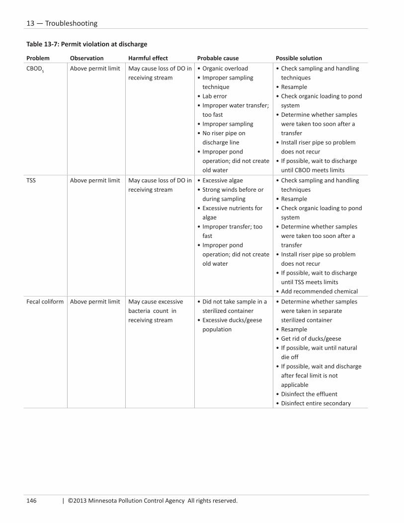
146 | ©2013 Minnesota Pollution Control Agency All rights reserved.
13 — Troubleshooting
Table 13-7: Permit violation at discharge
Problem Observation Harmful effect Probable cause Possible solutionCBOD5 Above permit limit May cause loss of DO in
receiving stream•Organicoverload•Impropersampling
technique•Laberror•Improperwatertransfer;
too fast•Impropersampling•Noriserpipeon
discharge line•Improperpond
operation; did not create old water
•Checksamplingandhandlingtechniques
•Resample•Checkorganicloadingtopond
system•Determinewhethersamples
were taken too soon after a transfer
•Installriserpipesoproblemdoes not recur
•Ifpossible,waittodischargeuntil CBOD meets limits
TSS Above permit limit May cause loss of DO in receiving stream
•Excessivealgae•Strongwindsbeforeor
during sampling•Excessivenutrientsfor
algae•Impropertransfer;too
fast•Improperpond
operation; did not create old water
•Checksamplingandhandlingtechniques
•Resample•Checkorganicloadingtopond
system•Determinewhethersamples
were taken too soon after a transfer
•Installriserpipesoproblemdoes not recur
•Ifpossible,waittodischargeuntil TSS meets limits
•AddrecommendedchemicalFecal coliform Above permit limit May cause excessive
bacteria count in receiving stream
•Didnottakesampleinasterilized container
•Excessiveducks/geesepopulation
•Determinewhethersampleswere taken in separate sterilized container
•Resample•Getridofducks/geese•Ifpossible,waituntilnatural
die off•Ifpossible,waitanddischarge
after fecal limit is not applicable
•Disinfecttheeffluent•Disinfectentiresecondary

Stabilization Pond Operation and Maintenance | 147
13 — Troubleshooting
Table 13-8: Excessive solids accumulation in primary
Problem Observation Harmful effect Probable cause Possible solutionSludge build-up in primary(s)
•Risingsludgemats or clumps
•Black/greywater•LowDO
(consistently less than 5 mg/L
•Odors•Increasedsolidsloadto
secondary
•Organicoverload•Normaltoaccumulate
over winter•Bacteria/algaenotin
proper balance
•Checkforexcessiveorganicloading
•Ifpossible,divertflowtoother primary
•Removesludge
Solids buildup at end of influent pipe
Island visible during low level water
•Blockageofinfluentline•Odorsifislandisexposed•Shallowareamay
develop excessive vegetation
•Excessivegritproblemincollection system
•Poordesignoninfluentpipe; inlet line is vertical instead of horizontal
•Correctbrokensewer•Checkinfluentline;repairif
needed•Carefullyremoveisland
with suction pump, etc.
Table 13-9: Leakage and seepage
Problem Observation Harmful effect Probable cause Possible solutionWater loss •Consistentlylow
water level•Emergent
vegetation over entire pond
•Groundwatercontamination
•Increasedvegetationdueto low water level
•Lowinfluentflow;ascompared to design flow
•Excessiveseepagethrough seal
•Deeprootedvegetation•Muskratsdamage•Seepagethrough/around
control structure
•Conductwaterbalancetodetermine actual seepage
•Patchholescausedbyanimals
•Removedeep-rootedvegetation and repair root damage
•Inspectcontrolstructure(s)for seepage

148 | ©2013 Minnesota Pollution Control Agency All rights reserved.
13 — Troubleshooting
Table 13-10: Control structures
Problem Observation Harmful effect Probable cause Possible solutionLeakage Less than normal pond
water depthInadequate water levels to maintain proper treatment
•Slidegatesareleakingbetween gate and guides
•Noshutoffvalveafterslide gates
•Leakbetweenconcretewalls and control structure wall
•Leakaroundoutsideofcontrol structure
•Machinegates•Installnewgates•Installgasket,ifpossible•Temporarilyplugareabetween
gates with bentonite or clay until permanent solution is found
•Installnewslides/guides•Groutconcretejoints•Installshutoffvalve
Corrosion •Slidegatesstuck•Pittingofmetal•Metaloxidebuild-up
on gates or slides
•Doesnotallowproper slide gate adjustment
•Can’toperatepond properly to create old water
•Poorventilation•Anaerobicconditionin
structure•Gatesandslidesare
different types of metal•Gatesandslidesarenot
corrosion resistant
•Installgratedcover•Cleanouttoreducebiological
activity in structure•Regularlylubricategatesand
slides•Installnewgatesandslides

Stabilization Pond Operation and Maintenance | 149
14 —Appendix A
AppendixA: Pump Calibration Procedure & Worksheet............................... 151
B: Emergency Notification ............................................................ 155
C: Solving Math Problems & Design Problems 1 & 2 .................... 157
D: Total Days Needed to Discharge ............................................... 161
E: Discharge Calculation Worksheet ............................................. 163
F: Discharge Evaluation Report ..................................................... 165
G: Dilution Ratio Worksheet ......................................................... 167
H: MPCA Compliance and Enforcement Coverage Areas .............. 169
I: Pond Worksheets & Spreadsheets ........................................... 171
•PumpCalibrationSpreadsheet—CircularWetWell ............. 173
•PumpCalibrationSpreadsheet—RectangularWetWell ...... 175
•GeometricMeanCalculationforFecalColiformResults ....... 177
•PumpReadingsinHours(thirdmeterrunswithothers ........ 179
•PumpReadingsinMinutes(thirdmeterrunswithothers) ... 181
•PumpReadingsInHours(thirdmeterindependent) ............. 183
•PumpReadingsInMinutes(thirdmeterindependent) ......... 185
J: References and Suggested Resource Material .......................... 187
14

150 | ©2013 Minnesota Pollution Control Agency All rights reserved.
14 — Appendix
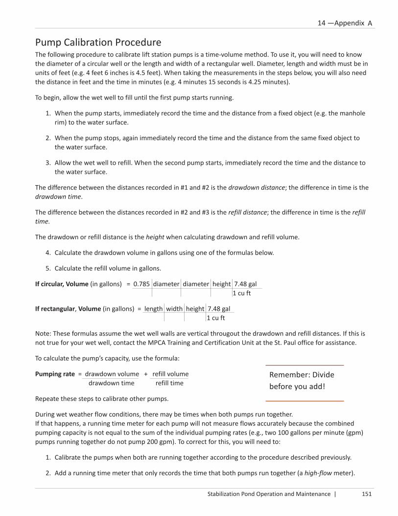
Stabilization Pond Operation and Maintenance | 151
14 —Appendix A
Pump Calibration ProcedureThe following procedure to calibrate lift station pumps is a time-volume method. To use it, you will need to know the diameter of a circular well or the length and width of a rectangular well. Diameter, length and width must be in units of feet (e.g. 4 feet 6 inches is 4.5 feet). When taking the measurements in the steps below, you will also need the distance in feet and the time in minutes (e.g. 4 minutes 15 seconds is 4.25 minutes).
To begin, allow the wet well to fill until the first pump starts running.
1. When the pump starts, immediately record the time and the distance from a fixed object (e.g. the manholerim) to the water surface.
2. When the pump stops, again immediately record the time and the distance from the same fixed object tothe water surface.
3. Allow the wet well to refill. When the second pump starts, immediately record the time and the distance tothe water surface.
The difference between the distances recorded in #1 and #2 is the drawdown distance; the difference in time is the drawdown time.
The difference between the distances recorded in #2 and #3 is the refill distance; the difference in time is the refill time.
The drawdown or refill distance is the height when calculating drawdown and refill volume.
4. Calculate the drawdown volume in gallons using one of the formulas below.
5. Calculate the refill volume in gallons.
If circular, Volume (in gallons) = 0.785 diameter diameter height 7.48 gal 1 cu ft
If rectangular, Volume (in gallons) = length width height 7.48 gal 1 cu ft
Note: These formulas assume the wet well walls are vertical througout the drawdown and refill distances. If this is not true for your wet well, contact the MPCA Training and Certification Unit at the St. Paul office for assistance.
To calculate the pump’s capacity, use the formula:
Pumping rate = drawdown volume + refill volume drawdown time refill time
Repeate these steps to calibrate other pumps.
During wet weather flow conditions, there may be times when both pumps run together. If that happens, a running time meter for each pump will not measure flows accurately because the combined pumping capacity is not equal to the sum of the individual pumping rates (e.g., two 100 gallons per minute (gpm) pumps running together do not pump 200 gpm). To correct for this, you will need to:
1. Calibrate the pumps when both are running together according to the procedure described previously.
2. Add a running time meter that only records the time that both pumps run together (a high-flow meter).
Remember: Divide before you add!
A

152 | ©2013 Minnesota Pollution Control Agency All rights reserved.
14 — Appendix
3. If all three running time meters are recording while both pumps are running, subtract the time from the high-flow meter from the others. After that, the running times from each meter can be used to calculate the actualdaily flow. For example:
• Two pumps each calibrated at 50-gpm capacity
• Both pumps running together calibrated at 75 gpm
• Each pump ran for 240 minutes one day
• Both pumps ran together for 100 minutes that same day
Sample calculation The operator at Happy Valley, Minnesota does not know the pumping capacity of their pumps in the main lift station. Using the information below, determine the pump’s capacity in gallons per minute.
• The diameter of the wet well is 8 feet
• Drawdown time = 4 minutes 15 seconds or 4.25 minutes
• Refill time = 6 minutes 45 seconds or 6.75 minutes
• Drawdown distance = 1 foot 3 inches or 1.25 feet
• Refill distance = 1 foot 2 inches or 1.17 feet
Formula: Volume (of a cylinder) = 0.785 x Diameter2 x Height
Drawdown Volume = 0.785 8 ft 8 ft 1.25 ft 7.48 gal = 469.74 gal 1 cubic ft
Refill Volume = 0.785 8 ft 8 ft 1.17 ft 7.48 gal = 439.68 gal 1 cubic ft
Pumping Rate = Drawdown Volume + Refill Volume Drawdown Time Refill Time
= 469.74 gal + 439.68 gal 4.25 min 6.75 min
= 110.52 gal/min + 65.13 gal/min = 175.65 gal/min
240 minutes - 100 minutes = 140 minutes (time pumps run separately)Pump 1 50 gpm x 140 minutes/day = 7,000 gal/dayPump 2 50 gpm x 140 minutes/day = 7,000 gal/dayPumps 1 & 2 75 gpm x 100 minutes/day = 7,500 gal/day
Total 21,500 gal/day
A
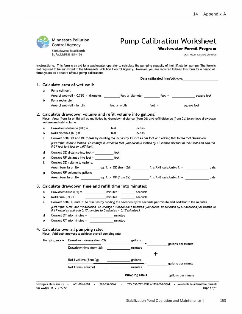
Stabilization Pond Operation and Maintenance | 153
14 —Appendix AA

154 | ©2013 Minnesota Pollution Control Agency All rights reserved.
14 — Appendix A

Stabilization Pond Operation and Maintenance | 155
14 —Appendix AB

156 | ©2013 Minnesota Pollution Control Agency All rights reserved.
14 — Appendix B

Stabilization Pond Operation and Maintenance | 157
14 —Appendix A
10 Steps to solving word problemsDo not be tempted to look at a problem and start punching numbers into a calculator. This only ensures you will get the wrong answer quickly. Instead, follow this method to help ensure success!
1. Read the problem carefully. (You may need to read it twice!)
2. Draw and label a picture of the problem.
3. Think about the information you are given and what you are trying to find.
4. Choose a formula. (Some problems may require more than one formula.)
5. Write down the formula as it is given. Rearrange it if it is not in the form you need.
6. Replace the words in the formula with the numbers and units of the information you have beengiven. Sometimes you may have information you don’t need and sometimes you will have to useconversion factors to change units you are given to those needed in the formula. Don’t let thatthrow you or fool you!
7. Cancel units in the formula to make sure the only units left are the ones you want in your answer.
8. Now, get out your calculator and carefully multiply all the numbers on the top and divide by all thenumbers on the bottom.
9. Ask yourself if the final answer is reasonable for the question being asked.
10. Double check to make sure your answer is in the units being asked for.
Congratulations! You should have the correct answer.
C

158 | ©2013 Minnesota Pollution Control Agency All rights reserved.
14 — Appendix C
Design problem #1You are operating a stabilization pond system that receives an average flow of 76,000 gpd with an average influent BOD of 220 mg/L. The primary pond is 750 feet long and 407 feet wide; the secondary is 750 feet long and 203 feet wide. The maximum depth is 6 feet; the minimum depth is 2 feet. Using this information, find:
1. The area, in acres, of the primary and secondary ponds.2. The storage volume, in gallons and acre-feet of the primary and secondary ponds.3. The total detention time, in days, between the maximum and minimum depths.4. The BOD loading, in pounds per day on the primary pond.5. The total primary pond organic loading, in pounds of BOD per acre per day.
1. Area = length x width
Primary pond area (acres) = 750 ft 407 ft 1 acre = 7 acres 43,560 sq ft
Secondary pond area (acres) = 750 ft 203 ft 1 acre = 3.5 acres 43,560 sq ft
2. Volume = length x width x height OR area x height
Primary volume (acre-ft) = 7 acres x 4 ft = 28.0 acre-ft 28.0 acre-ft 326,000 gal = 9,128,000 gal 1 acre-ft
Secondary volume (acre-ft) = 3.5 acres x 4 ft = 14.0 acre-ft 14.0 acre-ft 326,000 gal = 4,564,000 gal 1 acre-ft
3. Detention time (days) = total volume = 9,128,000 gal + 4,564,000 gal = 180 daysflow rate 76,000 gpd
4. Loading (lbs/day) = BOD (mg/L) x Flow (MGD) x 8.34 lbs/gal
Loading, primary = 220 mg/L x 0.076 MGD x 8.34 lbs/gal = 139 lbs/day
(Note: To convert gal/day to MGD, divide by 1,000,000)
5. Loading/acre = Total loading (lbs/day) = 139 lbs/day = 19.8 lbs/day/acreSize of pond (acres) 7.0 acres
Answers to Design Problem #2
1. Primary = 5.0 acres; secondary = 2.5 acres2. Primary = 20.0 acre-ft or 6,520,000 gallons; secondary = 10 acre-ft or 3,260,000 gallons3. 163 days4. 125.1 lbs/day5. 25.02 lbs/day/acre

Stabilization Pond Operation and Maintenance | 159
14 —Appendix A
Design problem #2You operate a stabilization pond system that receives an average flow of 60,000 gpd with an average influent BOD of 250 mg/L. The primary pond is 670 feet long and 325 feet wide; the secondary pond is 670 feet long and 163 feet wide. The maximum depth is 6 feet and the minimum depth is 2 feet. Using this information, find:
1. The area, in acres, of the primary and secondary ponds.
2. The storage volume, in gallons and acre-feet of the primary and secondary ponds.
3. The total detention time, in days, between the maximum and minimum depths.
4. The BOD loading, in pounds per day on the primary pond.
5. The total primary pond organic loading, in pounds of BOD per acre per day.
C

160 | ©2013 Minnesota Pollution Control Agency All rights reserved.
14 — Appendix C

Stabilization Pond Operation and Maintenance | 161
14 —Appendix AD
Total Days Needed to DischargeTo avoid discharging during the Problem Discharge Period, you must determine how long it will take to discharge enough water to allow adequate volume for storage and plan ahead for when you must begin the first discharge. Table D-1 will help you decide the total time needed to complete all the necessary discharges. The table is based on the assumption that the secondary pond is full and is ready to have pre-discharge samples taken.
Discharge #1: Six days are allowed for test results based on the BOD test, which takes five days, and allows for an extra day to receive results. Since the allowable discharge rate is six inches per day, a discharge of four feet will take eight days.
Time needed for discharge #1: 6 days (test results) + 8 days (discharge time) = 14 days
Discharge #2: Assuming you are transferring four feet of water from an upstream pond at six inches per day, the transfer will take eight days. Four days are allowed for settling — the time it typically takes to settle what was transferred.
Time needed for discharge #2: 8 days (transfer) + 4 days (settling) + 6 days (test results) + 8 days (discharge) = 26 days
Total time for discharges 1 & 2: 14 days + 26 days = 40 days
Discharge #3: Add 26 days (same as time needed for discharge #2) for this and all subsequent discharges.
If you need to discharge more than three times during each discharge window, it is likely because the secondary pond is not properly sized or a pump is not available to allow a complete filling of the secondary pond. In many older pond systems, the secondary pond is too small compared to the primary pond(s). Also, the elevation difference may not be adequate.
A properly designed pond system (both secondary pond size and adequate elevation difference) at design flow will have three discharges and will take approximately 66 days to discharge enough water to allow for either 180 or 210 days of storage time. This will allow an operator to stay within the Acceptable Discharge Period (see Table 7-1 on page 83).
Key to remaining within the Acceptable Discharge Period is a proper secondary pond size and a four-foot elevation difference between the primary and secondary pond. An adequate elevation difference allows the operator to completely fill the secondary pond before the first and each of the remaining discharges. Without a properly-sized secondary pond and sufficient elevation difference, the total days needed to discharge increases dramatically —sometimes as much as doubling the time. This will cause permit violations. One solution is to purchase a pump of sufficient size that will fill the secondary pond in eight days. If this cannot be done, then you will be increasing the number of discharges, possibly putting you out of the Acceptable Discharge Period and resulting in a permit violation.
Table D-1: Total days needed to discharge
Number of discharges needed*1 2 3 4 5
Transfer time 0 8 8 8 8Settle time (after transfer)
0 4 4 4 4
Test results 6 6 6 6 6Discharge time 8 8 8 8 8Days/discharge 14 26 26 26 26Total days all discharges
14 40 66 92 118
*With four feet difference in elevation or a pump of sufficient size

162 | ©2013 Minnesota Pollution Control Agency All rights reserved.
14 — Appendix D

Stabilization Pond Operation and Maintenance | 163
14 —Appendix AE

164 | ©2013 Minnesota Pollution Control Agency All rights reserved.
14 — Appendix E
Instructions for the Pond Discharge Calculation WorksheetThis form is provided as an aid for the stabilization pond operator to calculate the amount of treated wastewater to discharge in order to provide the approximate storage needed for the upcoming summer or winter time period. The assumption used in this calculation is that rainfall will equal pond seepage plus pond evaporation. The form has been created to be used electronically. After you enter your numbers in the ‘yellow’ form field boxes, the ‘orange’ and ‘green’ form field boxes will automatically be populated with the calculations. The form is not required to be submitted to the Minnesota Pollution Conrol Agency. However, you are required to keep this form for a period of three years as a record of your pond discharge calculations.
This worksheet is available on the MPCA website at: http://www.pca.state.mn.us/f9ap8yx.
Example: Calculating discharge volumeAn operator has taken pre-discharge samples and is ready to discharge to provide adequate storage.
Given the following information, determine how many feet of water the operator must remove from the secondary pond to provide adequate storage. Also, calculate how many days that will take.
• Surface area of primary pond = 6 acres
• Surface area of secondary pond = 3 acres
• Difference in pond bottom elevations = 4 feet
• Daily average flow = 55,000 gallons/day
• Storage time needed = 195 days
• Maximum pond depths = 6 feet
• Minimum pond depths = 2 feet
• Measured depth of primary pond = 3 feet
• Measured depth of secondary pond = 6 feet
A total of 4.97 feet will be discharged. Two discharges will be needed. The first discharge will be for a discharge of four feet. The second one will be for the balance of 4.97 feet minus four feet that was previously discharged or 0.97 feet (after transfer from the primary).
The total days for discharging will be as follows:
1. Discharge four feet from the secondary at six inches per day = 8 days2. Transfer two feet from the primary at six inches per day = 4 days 3. Wait 4 days for secondary to settle = 4 days4. Sample secondary and wait for results = 6 days 5. Discharge one foot from secondary = 2 days6. Total days needed to discharge a total of 5 feet = 24 days
To help you do this calculation, refer to the Discharge Calculation Worksheet in Appendix E. Also see Appendix I to see a paper copy of a spreadsheet that is available electronically to help you do this calculation. The electronic spreadsheet is available on the MPCA website at: http://www.pca.state.mn.us/f9ap8yx.

Stabilization Pond Operation and Maintenance | 165
14 —Appendix AF

166 | ©2013 Minnesota Pollution Control Agency All rights reserved.
14 — Appendix F

Stabilization Pond Operation and Maintenance | 167
14 —Appendix AG

168 | ©2013 Minnesota Pollution Control Agency All rights reserved.
14 — Appendix G

Stabilization Pond Operation and Maintenance | 169
14 —Appendix AH
Contact Information
MPCA Regional Offices
Brainerd7678 College Road — Suite 105 Baxter, MN 56425 218-828-2492, 800-657-3864Fax: 218-828-2594
Detroit Lakes714 Lake Avenue — Suite 220 Detroit Lakes, MN 56501 218-847-1519, 800-657-3864Fax: 218-846-0719
Duluth525 Lake Avenue South — Suite 400 Duluth, MN 55802 218-723-4660, 800-657-3864Fax: 218-723-4727
Mankato12 Civic Center Plaza — Suite 2165 Mankato, MN 56001 507-389-5977, 800-657-3864Fax: 507-389-5422
Marshall504 Fairgrounds Road — Suite 200 Marshall, MN 56258 507 537-7146, 800-657-3864 Fax: 507 537-6001
Rochester18 Wood Lake Drive SE Rochester, MN 55904 507-285-7343, 800-657-3864Fax: 507-280-5513
St. Paul520 Lafayette Road North St. Paul, MN 55155-4194 651-296-6300, 800-657-3864TTY: 651-282-5332
Willmar 1601 Highway 12 East — Suite 1 Willmar, MN 56201-6002 320-214-3786, 800-657-3864Fax: 320-214-3787
See http://www.pca.state.mn.us/iryp3e4 for a map of regional boundaries.
See http://www.pca.state.mn.us/publications/wq-wwtp1-10.pdf for a map of compliance and enforcement staff coverage areas. On the home page (http://www.pca.state.mn.us), click on “Water” in the menu bar. Then, click on “Wastewater” and scroll to locate the document “Municipal and Industrial Wastewater Facility Compliance and Enforcement Coverage Areas.”

170 | ©2013 Minnesota Pollution Control Agency All rights reserved.
14 — Appendix H

Stabilization Pond Operation and Maintenance | 171
14 —Appendix AI
Appendix I is a collection of copies of electronic worksheets and spreadsheets designed by MPCA staff to help pond operators perform various calculations, some of which are required by your NPDES permit. When using one of these, the resulting calculations are records, which you must keep for a period of at least three years.
To access electronic copies of all of these documents (and others), see the MPCA website: http://www.pca.state.mn.us/f9ap8yx
• Pump Calibration Spreadsheet — Circular Wet Well (Excel) [wq-wwtp7-32] ................................. 173
• Pump Calibration Spreadsheet — Rectangular Wet Well (Excel) [wq-wwtp7-33] ........................... 175
• Geometric Mean Calculation for Fecal Coliform Results (Excel) [wq-wwtp7-34] ............................ 177
• Pump Readings in Hours (third meter runs with the other two) (Excel) [wq-wwtp7-35] ................ 179
• Pump Readings in Minutes (third meter runs with the other two) (Excel) [wq-wwtp7-36] ............ 181
• Pump Readings in Hours (third meter independent of the other two) (Excel) [wq-wwtp7-37] ...... 183
• Pump Readings in Minutes (third meter independent of the other two) (Excel) [wq-wwtp7-38] .. 185

172 | ©2013 Minnesota Pollution Control Agency All rights reserved.
14 — Appendix I

Stabilization Pond Operation and Maintenance | 173
14 —Appendix AI

174 | ©2013 Minnesota Pollution Control Agency All rights reserved.
14 — Appendix I
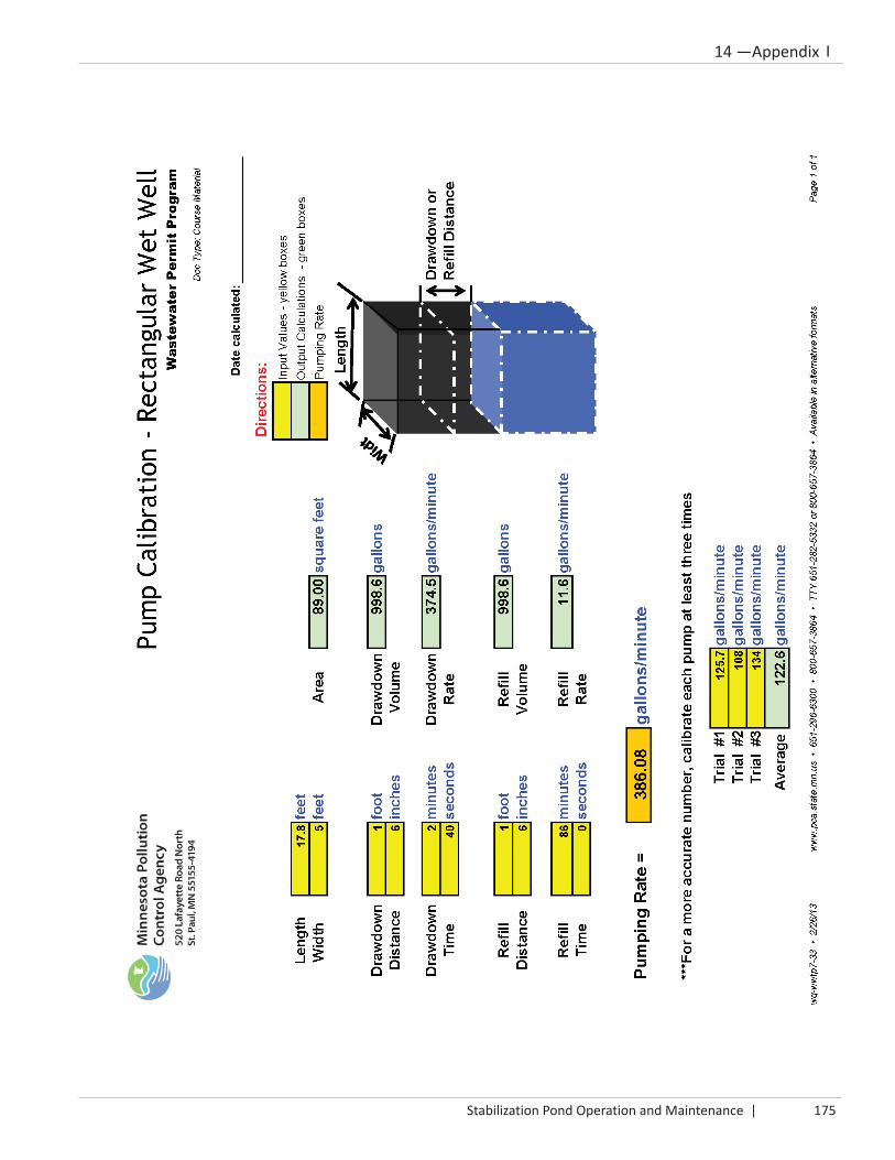
Stabilization Pond Operation and Maintenance | 175
14 —Appendix AI

176 | ©2013 Minnesota Pollution Control Agency All rights reserved.
14 — Appendix I

Stabilization Pond Operation and Maintenance | 177
14 —Appendix AI

178 | ©2013 Minnesota Pollution Control Agency All rights reserved.
14 — Appendix I

Stabilization Pond Operation and Maintenance | 179
14 —Appendix AI

180 | ©2013 Minnesota Pollution Control Agency All rights reserved.
14 — Appendix I

Stabilization Pond Operation and Maintenance | 181
14 —Appendix AI

182 | ©2013 Minnesota Pollution Control Agency All rights reserved.
14 — Appendix I

Stabilization Pond Operation and Maintenance | 183
14 —Appendix AI

184 | ©2013 Minnesota Pollution Control Agency All rights reserved.
14 — Appendix I

Stabilization Pond Operation and Maintenance | 185
14 —Appendix AI

186 | ©2013 Minnesota Pollution Control Agency All rights reserved.
14 — Appendix I
Stabilization Pond Operation and Maintenance | 187
14 —Appendix AJ
References and suggested resource material• APHA, AWWA, WEF. Standard Methods for the Examination of Water and Wastewater. 18th edition,
Washington: APHA, 1992
• Applied Biochemists, Inc. How to Identify and Control Water Weeds and Algae. Mequon: AppliedBiochemists, Inc., 1976
• Brock, Thomas D. Biology of Microorganisms. Englewood Cliffs: Prentice-Hall, Inc., 1970
• Eldon De Camp. Operating Waste Stabilization Ponds. Cedar Rapids: Kirkwood Community College,Environmental Occupations Department under contract with EPA, Manpower Training Program, RegionVII, 1975.
• Gloyna, D. Eng. Earnest F. Waste Stabilization Ponds. Geneva: World Health Organization, 1971
• Hammer, J. Mark. Water and Wastewater Technology. New York: John Wiley & Sons, Inc., 1975
• Hiatt, A.L. “Waste Treatment Ponds,” Operation of Wastewater Treatment Plants, A Field Study TrainingProgram. Chapter 9. Sacramento: Sacramento State College, Dept. of Civil Engineering for U.S. EPA,Technical Grant No. 5TT1-WP-16-03, 1970
• Iowa Department of Environmental Quality. Waste Facultative Pond Operations Manual. Des Moines, nodate.
• Kerri, Kenneth D. Project Director. Operation and Maintenance of Wastewater Collection Systems,Operation of Wastewater Treatment Plants, A Field Study Training Program. Sacramento: CaliforniaState University, Dept. of Civil Engineering for U.S. EPA, Municipal Permit and Operation Division, GrantNo. T900690010, 1992.
• Maine Department of Environmental Protection. “Lagoon Systems in Maine,” An InformationalResource for Operators of Lagoon Systems, http://lagoonsonline.com
• Metcalk & Eddy, Inc. Wastewater Engineering: Collection, Treatment and Disposal. New York: McGraw-Hill, Inc., 1991. Third edition.
• Michigan Department of Natural Resources, Environmental Protection Bureau, Water Quality Division,Training and Certification Section. Lagoon Operator Training Manual. Lansing: DNR, 1977
• Middlebrooks, Jones, Reynolds, Torpy, Bishop. Lagoon Information Source Book. Michigan: Ann ArborScience, 1978.
• Minnesota Pollution Control Agency, Recommended Pond Design Criteria (wq-wwtp5-53), December2009.
• New York State Department of Health and others. Manual of Instruction for Sewage Treatment PlantOperators. Albany: New Your State Dept. of Health, no date.
• Oregon Department of Environmental Quality. Information for Domestic Sewage Lagoons orStabilization Ponds. Portland: DEQ, February 1977.
• “Ponds as a Wastewater Treatment Alternative,” Water Resources Symposium Number Nine. Austin:Center for Research in Water Resources, University of Texas, 1976.
• Principles of Design and Operations of Wastewater Treatment Pond Systems for Plant Operators,Engineers, and Managers. U.S. EPA Office of Research and Development, National Risk ManagementResearch Laboratory - Land Remediation and Pollution Control Division. EPA/600/R-11/088. August2011.

188 | ©2013 Minnesota Pollution Control Agency All rights reserved.
14 — Appendix J
• Second International Symposium for Waste Treatment Lagoons. Kansas City, Missouri: Missouri Basin Engineering Health Council & FWQA, June 23-25, 1975.
• Texas Water Utilities Association. Manual of Wastewater Operations, Fourth Edition. Lancaster: Lancaster Press, 1971.
• University of Minnesota. St. Anthony Falls Hydraulic Laboratory. “Modeling Daphnia Population in Wastewater Stabilization Ponds in Minnesota,” Project Report No. 325, Hathaway and Stafan, June 1992.
• “Upgrading Wastewater Stabilization Ponds to Meet New Discharge Standards,” Proceedings of a Symposium held at Logan State University, Utah, August 21-23, 1974. Logan: Utah Water Research Laboratory and NERC, U.S. EPA, Cincinnati, November 1974.
• Virginia State Water Control Board, Bureau of Applied Technology Training Division. Stabilization Ponds and Lagoons. 1976.
• WEF. Operation of Wastewater Treatment Plants Manual of Practice 11, 2007.
• Zickefoose, Chuck and R.B. Joe Hayes. Operations Manual Stabilization Ponds. Washington, D. C.: U.S. EPA Office of Water Program Operations, EPA-430/9-77-012, August 1977.


Related Documents