Welcome message from author
This document is posted to help you gain knowledge. Please leave a comment to let me know what you think about it! Share it to your friends and learn new things together.
Transcript
Stabilization of periodic orbits of the buck converter bytime-delayed feedback�Carles Batlley, Enric Fossasz, and Gerard OlivarxDept. de Matem�atica Aplicada i Telem�atica, UPCEUPVG, Av. V. Balaguer s/n Vilanova i la Geltr�u 08800 SPAINAbstractTime-delay autosynchronization (TDAS) can be used to stabilize unstable pe-riodic orbits in dynamical systems. The technique involves continuous feedback ofsignals delayed by the orbit's period so that the feedback signal vanishes on thetarget orbit and hence the later is a solution of the original dynamical system.Furthermore, this control method only requires the knowledge of the period ofthe unstable orbit. The feedback gain needed to achieve stabilization varies withthe bifurcation parameter(s) of the system, resulting in a domain of control, thecomputation of which requires, in general, detailed information about the targetorbit(s).In this paper we compute the domain of control of the unstable periodic orbitsof the PWM controlled buck converter for a couple of TDAS schemes. For bothschemes we get an analytical expression for the closed curve whose index deter-mines the stability, and this index is then numerically computed. We run severalsimulations of the controlled systems and discuss the results. The main result isthat TDAS greatly increases the range of values of the input voltage where thePWM control yields a periodic orbit with a small rippling.1 IntroductionControl of chaos, meaning supression of the chaotic regime in a system by means of asmall, time-dependent perturbation, has been a subject of interest in recent years [1].In [2] it was pointed out that the many unstable periodic orbits (UPOs) embedded ina strange attractor could be used to produce regular behaviour to the advantage of�Work partially supported by CICYT under Projects TAP94-0552 and [email protected]@[email protected] 1

engineers trying to control nonlinear systems in which chaotic uctuations are presentbut undesirable.Pyragas [3] proposed a method, called time-delayed autosynchronization, whichinvolves a control signal formed with the di�erence between the current state of thesystem and the state delayed by one period of the UPO. Theoretical justi�cation of thismethod has been put forward in [4] and partial characterization, in terms of the Floquetexponents of the original system, of cases when TDAS cannot work has been performedin [5]. Variants, involving combinations of signals from the system delayed by in�niteinteger multiples of the UPO's period [6], or nonlinear functions of the delayed signal[7], have also been proposed. TDAS and its variants have the advantage that the onlyinformation needed about the target orbit is its period, and that no computer processingmust be done to generate the control signal, in contrast with the OGY method [2]. Themethod has even been applied to spatially extended systems [8][9].In general, the feedback gain which succesfully stabilizes the orbit lies in a �nite, andoften narrow, orbit dependent range. When viewed in the space of the feedback gain andthe bifurcation parameter(s) of the system, the region where TDAS can be successfullyapplied is called the domain of control of the TDAS. In [8][10] a method was proposedto compute the domain of control of a given TDAS scheme without having to explicitlyintegrate the resulting time-delay equations. The relevant time-dependent linear dif-ferential equation, containing detailed information about the target orbit, must be, ingeneral, numerically integrated. However, for a class of nonlinear systems, those whosevector �eld is piecewise linear, this integration can be done analytically. In particular,this has been applied to several PWM controlled dc-dc converters. [11][12][13]Figure 1 shows the basic scheme of the voltage-controlled buck converter (see [14]and references therein for a description of this DC-DC power converter). Essentially,the load voltage v(t) is compared with a periodic rampr(t) = Vref + VL� + VU � VL�T twith t evaluated mod T , and the switch S is open if v(t) > r(t) and closed otherwise.If we assume that the inductor current i(t) is always positive, the system has only twotopologies and is described bydvdt = � 1RCv + 1C i; didt = � 1Lv + ELu(t)where u(t) = 1 � �(v � r(t)). Notice that the system is nonlinear only because of thestate space depending changing topology. The input voltage E acts as a bifurcationparameter. We refer to [14, 15, 16] for detailed descriptions of the bifurcation diagrammof this system and its chaotic regime. Methods of stabilization of its UPOs based onmodi�cations of the OGY techniques ans others have been analyzed [17][18]. In all the2
�� ��� BBB������#" !
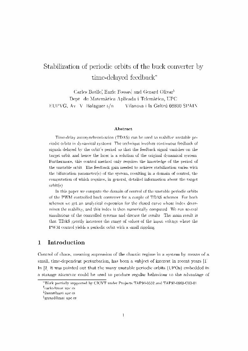
S L RE Civ-6 6
Figure 1: The basic scheme of the buck converter. The two topologies correspond to Sopen and the diode conducting and to S closed and the diode in inverse polarization(closed).numerical computations in this paper we will use the values R = 22 , C = 47 �F,L = 20 mH, � = 8:4, T = 400 �s, VL = 3:8 V, VU = 8:2 V, Vref = 11:3 V and E varyingin the range [20; 35] V.We propose two TDAS schemes for the buck converter, which we call active andpassive. In the �rst, or active scheme, a voltage source �v(t) = �(v(t) � v(t � �))is added to the load branch in such a way that the di�erential equation for the totalvoltage in the load branch becomesdvdt = � 1RCv + 1C i+ �RC (v(t) � v(t� �)):Here � is a dimensionless feedback gain and � is the period of the target UPO, a multipleof the ramp's period T . In the second, or passive scheme, no power is injected into thecircuit but now the signal which is compared to the ramp to determine the change intopology is v(t)� � [M1(v(t) � v(t� �)) +M2(i(t)� i(t� �))] ;instead of v(t). Again � is a dimensionless feedback gain, whileM1, also dimensionless,and M2, measured in ohms, are adjustable parameters describing the coupling of thefeedback signal to the system. Notice that in both schemes the feedback signal vanisheson the target ��periodic UPO.We will be concerned with the stabilization of T�periodic orbits of the buck con-verter which cross the ramp exactly once per ramp-period, and such that at the begin-ning of every period one has v > r(t). More general situations, such as stabilization ofhigher periodic orbits, can be easily treated as well, as described in [11].3
The paper is organized as follows. Floquet exponents for the T�periodic orbits ofthe buck converter are analytically computed in Section 2. In Section 3 we describethe method of Bleich and Socolar [8] to compute the domain of control and apply itto the two TDAS schemes for the buck converter, obtaining analytical expressions forthe curve whose index determines the succes of the stabilization. Section 4 is devotedto the numerical computations of the index for the various schemes and to numericalsimulations of the time-delay controlled systems. Finally, we state our conclussions inSection 5.2 Floquet exponents of the buck converterSince it is relevant to our posterior analysis and we have not found any explicit referencein the literature, we compute here the Floquet exponents for the T�periodic orbits ofthe buck converter. We refer to [19] for a detailed presentation of the theory of linear,periodic coe�cient di�erential systems.Consider a system driven by a ��periodic vector �eld_x = f(x; t) ; f(x; t+ �) = f(x; t); (1)and assume that it has a ��periodic orbit x�(t+ �) = x�(t). A linear stability analysiswith x = x� + � yields the following equation for the displacement_� = Dxf(x�; t)�: (2)The matrix Dxf(x�; t) is ��periodic since both the explicit t dependence and thedependence through x� are ��periodic. Hence (2) is a linear system for � with time-periodic coe�cients. Floquet theory tells us to look for solutions of the form��(t) = e�tu�(t) (3)where � is a complex number called a Floquet exponent an u�(t) veri�esu�(t+ �) = u�(t) (4)The periodicity condition (4) determines the allowed values of �. From (2) and (3) weget for u� �u�(t) + _u�(t) = Dxf(x�; t)u�(t): (5)If x� is to be assimptotically stable, all the solutions of (4) (5) must obey <(�) < 0.Equation (5) admits a formal solutionu�(t) = U�(t)u�(0) (6)4

in terms of a time-ordered matrix exponentialU�(t) = P exp�Z t0 (Dxf(x�(t0); t0)� �) dt0� : (7)The periodicity condition on u� imposes u�(0) = U�(�)u�(0), and thus the Floquetexponents are determined by det (U�(�)� I) = 0 (8)In most cases U�(�) cannot be computed from the matrix exponential (7) and one mustfall back to the numerical integration of equation (5).For the buck converter, the vector �eld f(x; t) is, with x = (v; i)T ,f(x; t) = �1=(RC) 1=C�1=L 0 ! vi !+ EL 01 ! (1� �(v � r(t)))If we write u�(t) = (x(t); y(t))T , equation (5) becomes_x = �� 1RC � ��x+ 1C y_y = �� 1L � EL �(v�(t)� r(t))� x� �y (9)As explained in Section I, we assume that v� crosses the ramp at t = tc, mod T ,and hence �(v�(t)� r(t)) = 1j _v�(tc)� _r(tc)j�(t � tc) � ��(t� tc); (10)so (9) becomes _x = � (2k + �)x+ 1C y_y = � 1L(1 + �E�(t � tc))x� �y; (11)where k = 1=(2RC) and, for future use, we also de�ne ! = (1=(LC)� k2)1=2, which isa real number for the numerical values of our circuit parameters. System (11) can beintegrated analytically because the time-dependent, Dirac delta term only introducesa jump of value ��E=Lx(tc) for y(t) at t = tc. In fact, system (11) is a particularinstance of the general equation_x = f(x) + �(t � tc)Ax; (12)5
where x 2 Rn and A is a matrix. For such system, the jump at t = tc is given by [20]x(tc+) = eAx(tc�): (13)In our case, A = 0 0��EL 0 ! (14)and computing the exponential one indeed gets that there is no jump for x(t) whiley(tc+) = y(tc�)� �ELx(tc�). Hence one can obtainU�(T ) = A11 A12A21 A22 ! and det(U�(T )� I) = (A11A22 �A12A21)� (A11 +A22) + 1withA11 = � 1!e�(k+�)T (k sin!T � ! cos!T ) (15)+ E�LC!2 e�(k+�)T sin!(T � tc)(k sin!tc � ! cos!tc)A12 = 1!C e�(k+�)T sin!T + E�LC2!2 e�(k+�)T sin!(T � tc) sin!tcA21 = � 1!Le�(k+�)T sin!T+ E�L!2 e�(k+�)T (k sin!(T � tc) + ! cos!(T � tc)) (k sin!tc � ! cos!tc)A22 = 1!e�(k+�)T (k sin!T + ! cos!T )� E�LC!2 e�(k+�)T (k sin!(T � tc) + ! cos!(T � tc)) sin!tc (16)Notice that (A11A21)T and (A12A22)T are the solutions at t = T corresponding tothe initial conditions (1 0)T and (0 1)T , respectively. Hence A11A22 � A12A21 is theWronskian, at t = T , of those solutions, and can be computed directly from the traceof (11) without using (16): A11A22 �A12A21 = e�2(k+�)T :Calculating A11 + A22 from (16) one �nally gets the determining equation for theFloquet exponentse�2(k+�)T � e�(k+�)T �2 cos!T � E�LC! sin!T�+ 1 = 0: (17)Notice that in the above expression the orbit dependent information in entirely con-tained in the product E�. We can solve (17) for � in terms of E� and get the twoFloquet exponents �(E�) = �k � 1T log'�(E�); (18)6
0.0085
0.009
0.0095
0.01
0.0105
0.011
0.0115
0.012
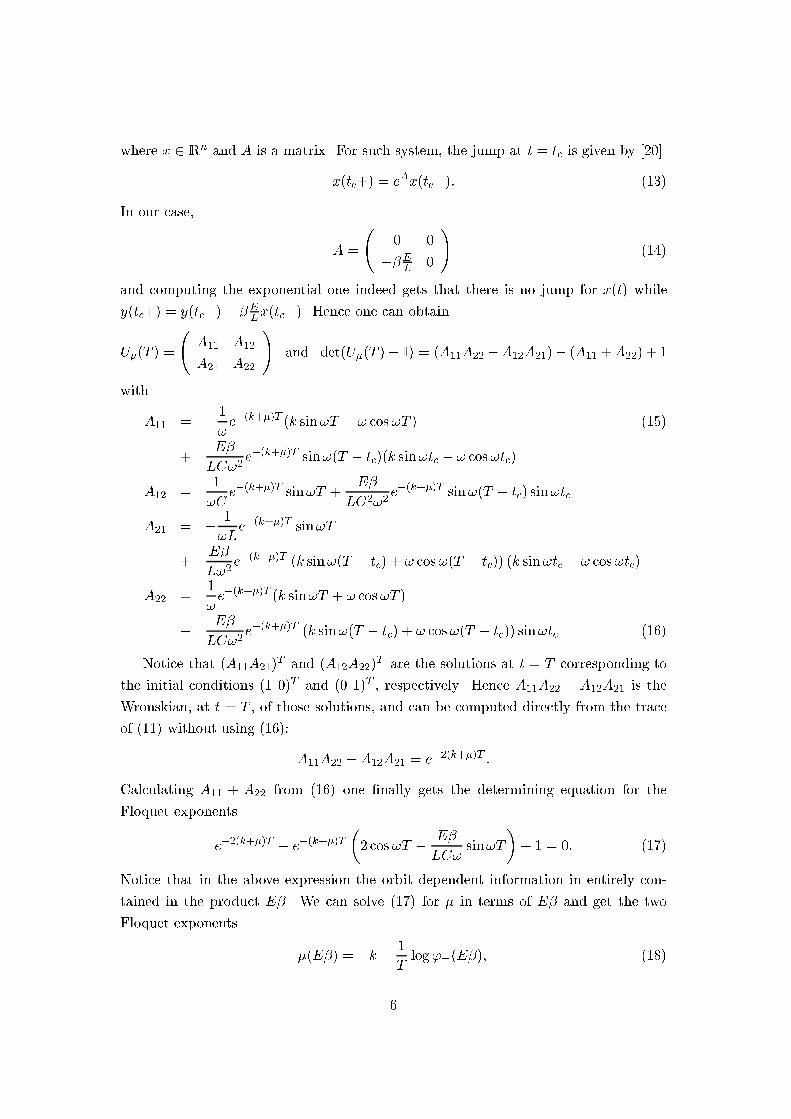
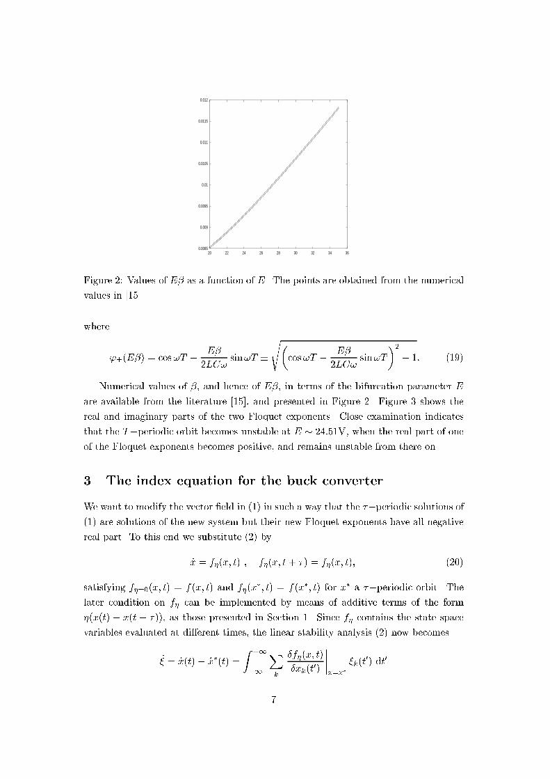
20 22 24 26 28 30 32 34 36Figure 2: Values of E� as a function of E. The points are obtained from the numericalvalues in [15].where'�(E�) = cos!T � E�2LC! sin!T �s�cos!T � E�2LC! sin!T�2 � 1: (19)Numerical values of �, and hence of E�, in terms of the bifurcation parameter Eare available from the literature [15], and presented in Figure 2. Figure 3 shows thereal and imaginary parts of the two Floquet exponents. Close examination indicatesthat the T�periodic orbit becomes unstable at E � 24:51V, when the real part of oneof the Floquet exponents becomes positive, and remains unstable from there on.3 The index equation for the buck converterWe want to modify the vector �eld in (1) in such a way that the ��periodic solutions of(1) are solutions of the new system but their new Floquet exponents have all negativereal part. To this end we substitute (2) by_x = f�(x; t) ; f�(x; t+ �) = f�(x; t); (20)satisfying f�=0(x; t) = f(x; t) and f�(x�; t) = f(x�; t) for x� a ��periodic orbit. Thelater condition on f� can be implemented by means of additive terms of the form�(x(t) � x(t � �)), as those presented in Section 1. Since f� contains the state spacevariables evaluated at di�erent times, the linear stability analysis (2) now becomes_� = _x(t)� _x�(t) = Z +1�1 Xk �f�(x; t)�xk(t0) ����x=x� �k(t0) dt07
-3000
-2500
-2000
-1500
-1000
-500
0
500
1000
1500
2000
0.0085 0.009 0.0095 0.01 0.0105 0.011 0.0115 0.012-8000
-6000
-4000
-2000
0
2000
4000
6000
8000
0.0085 0.009 0.0095 0.01 0.0105 0.011 0.0115 0.012Figure 3: Real and imaginary parts of the Floquet exponents of the buck converter asa funcion of E�. When the real parts split, the imaginary parts collapse to a uniquevalue, which corresponds to ��=T , indicating that the Floquet multipliers exp(�=T )become real and negative. At E� � 0:94 one of the real parts becomes positive, whichmeans that one of the Floquet multipliers crosses the unit circle at �1.For f� of the form we are going to work with, i.e. local in x(t) and x(t� �), the abovefunctional derivatives yield terms with �(t� t0) and �(t� � � t0), so �nally_�(t) = A0(t)�(t) +A1(t)�(t� �); (21)where both A0(t) and A1(t) are ��periodic. Equation (21) is thus a linear, time-delayed, periodic coe�cient system of di�erential equations for �. Since a time-delayeddi�erential equation is equivalent to an in�nite dimensional system of ordinary di�eren-tial equations, we have an in�nite dimensional Floquet problem (see [21] for the theoryof time-delayed di�erential equations). In any case, we have to look again for solutionsof the form ��(t) = e�� tp�(t); (22)where p� is ��periodic and we have written the Floquet exponent as �� . The di�erentialequation for p� is _p� = �A0(t)� �� I� p� + e��A1(t)p� (23)8

which is an ordinary di�erential equation, just a s in the case of �nite dimensionalFloquet theory. Again, the formal solution to (23) isp�(t) = P exp�Z t0 �A0(t0) + e��A1(t0)� �� I� dt0� p�(0) (24)= U�(t) p�(0) (25)(This U� di�ers by exp(��t=�) from the evolution operator used in [8], but the reason-ing is the same). The periodicity condition imposes det(U�(�)�I) = 0, which, de�ninge�� = z, becomes g(z) � det(U� log z(�)� I) = 0 (26)The linear stability condition is thus equivalent to the requirement that all the zerosof g(z) are outside the unit circle. However, due to the time-delay character of theoriginal problem, g(z) has now an in�nite number of zeros corresponding to the in�nitedimensions in phase space, and a better way than their explicit computation must bedevised to �nd out their locations. SinceU� log z(�) = z Pexp�Z �0 (A0(t) + zA1(t)) dt� (27)has no poles inside the unit circle, by a well-known theorem of complex analysis, thenumber of zeros of g(z) inside the unit circle equals the index of the curve g(z) whenz runs over the unit circle. Hence the periodic orbit x� is linearly asimptotically stableif and only if the index of g(z) around the origin when z 2 S1 is zero.We will now apply the above result to the two TDAS schemes proposed for the buckconverter.For the active scheme the vector �eld isf�(x; t) = � 1RC 1C� 1L 0 ! vi !+ EL 01 ! (1� �(v � r(t))) + �RC 10 ! (v(t)� v(t� T ))and (23) becomes, with p�(t) � (x(t) y(t))T ,_x = �� 1RC (1� � + �e��)� �� �x+ 1Cy_y = �� 1L � EL�(v�(t)� r(t))� x� �� yor, using (10), _x = � (2k(1 � � + �e��) + �� )x+ 1Cy_y = � 1L(1 + �E�(t � tc))x� �� y (28)9

It is seen that this system is (11) with the obvious identi�cations. Hence the corre-sponding equation (26) can be obtained from (17):e�2(k̂+�=�)T � e�(k̂+�=�)T �2 cos !̂T � E�LC!̂ sin !̂T�+ 1 = 0: (29)where k̂ = k(1 � � + �e��) ; !̂ = � 1LC � k̂2�1=2 :We get �nally g(z) = z2e�2k̂T � ze�k̂T �2 cos !̂T � E�LC!̂ sin !̂T�+ 1: (30)Notice that in this expression k̂ and !̂ depend on z, and that g(z) depends analyticallyon z since no odd orders of !̂ are present in the corresponding power expansion.For the passive TDAS scheme the modi�ed vector �eld isf�(x; t) = �1=(RC) 1=C�1=L 0 ! vi !+ EL 01 ! (1� � [v(t)� r(t)� �M1(v(t)� v(t� T ))� �M2(i(t) � i(t� T ))])and, using (10), equation (23) is now_x = � (2k + �� )x+ 1Cy_y = � 1Lx+ p�(t� tc)x+ q�(t� tc)y � �� y (31)with p = ��EL �1� �M1(1� e��)�q = �EL �M2 �1� e��� :In the notation of (12) we have nowA = 0 0p q ! (32)and the jump can again be computed using (13). The �nal result is the followingexpression for g(z):g(z) = z2e�2kT+q � z e�kT!2LC (K1 cos!T +K2 sin!T ) + 1; (33)with K1 = (1� k2LC)(1 + eq)K2 = L!(pq + kC)(eq � 1)10

20 22 24 26 28 30 32 34
-10
-5
0
5
10
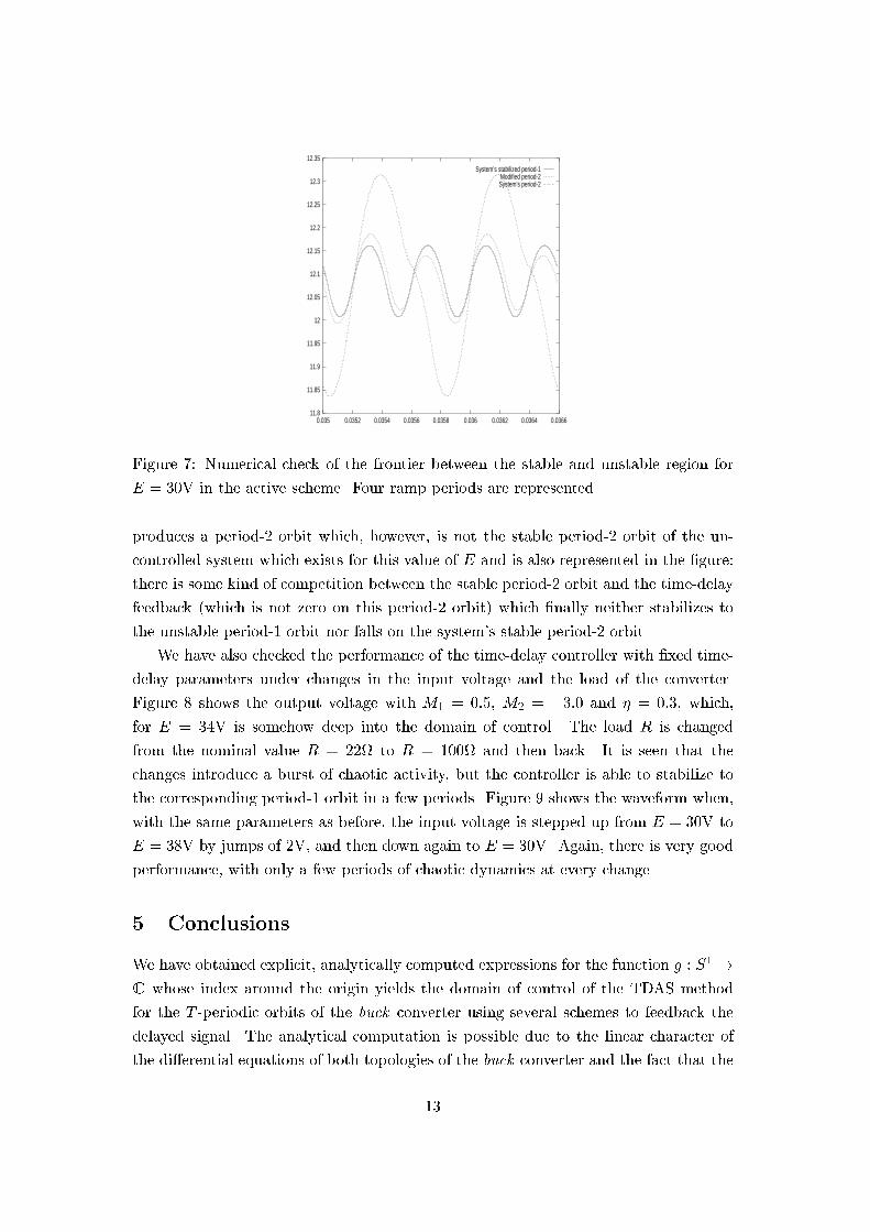
Figure 4: Domain of control for the active scheme. Vertical axis: � 2 [�10; 10]. Hori-zontal axis: E from 20V to 35V. Black: index = 0 (stable), Grey: index = 1 (unstable),White: index = 2 (unstable).4 Numerical analysis and simulationsWe can now numerically evaluate the index of g(z) using the analytical expressions ob-tained in the previous Section. To this end, g(z) is evaluated over S1 using a su�cientlydense set of complex points. The complex algebra has been numerically implementedwith the complex library of the GNU g++ compiler. Figure 4 shows the domain of con-trol for the active scheme and Figure 5 displays the domains of control for the passivescheme and several values of the couplings M1 and M2.We have run many simulations of the time-delay controlled systems to get a feelingfor the efectiveness of the method, and some of them are reported here. Figure 6 showssimulations using the passive TDAS scheme with � = 0:5, M1 = 0:1 and M2 = �4:0for both E = 28 and E = 34. In both cases the control starts to act after 80 periods ofthe ramp, so in the initial part the system exhibits the natural 2T -periodic and chaoticwaveforms, respectivelly. It is seen that the the control needs a transient of only a fewperiods to stabilize the T -periodic orbit.In order to check the frontier between the zones of the domain of control, we havenumerically integrated the time-delay feedback equations for several values of the bifur-cation parameter E and the feedback gain � on both sides of the analytically computedfrontier, although some times numerical integration errors may produce a wrong resultif � is too close to the frontier. One of those checks is presented in Figure 7, whichcorresponds to input voltage E = 30 with the �rst feedback scheme. The solid linecorresponds to � = �1:3 and the dashed one to � = �1:2. The expression (30) for g(z)predicts index 0 for the former and index 1 for the later. We see indeed that � = �1:3stabilizes the system to the period-1 orbit, while � = �1:2 does not. In fact, � = �1:211

20 22 24 26 28 30 32 34
-1-0.5
00.5
1
20 22 24 26 28 30 32 34
-1-0.5
00.5
1Figure 5: Domains of control for the passive scheme and several values of the couplingparameters: [M1 = 0:1, M2 = �4:0] and [M1 = 0:5, M2 = �3:0]. Vertical axis:� 2 [�1; 1]. Horizontal axis: E from 20V to 35V. Black: index = 0 (stable), Grey:index = 1 (unstable), White: index = 2 (unstable).
10
11
12
13
14
15
16
0 0.01 0.02 0.03 0.04 0.05 0.06
output voltage
10
11
12
13
14
15
16
0 0.01 0.02 0.03 0.04 0.05 0.06
output voltage
Figure 6: Time-delay feedback simulations for E = 28V and E = 34V using the passivescheme with � = 0:5, M1 = 0:1 and M2 = �4:0.12
11.8
11.85
11.9
11.95
12
12.05
12.1
12.15
12.2
12.25
12.3
12.35
0.035 0.0352 0.0354 0.0356 0.0358 0.036 0.0362 0.0364 0.0366
System’s stabilized period-1Modified period-2System’s period-2
Figure 7: Numerical check of the frontier between the stable and unstable region forE = 30V in the active scheme. Four ramp periods are represented.produces a period-2 orbit which, however, is not the stable period-2 orbit of the un-controlled system which exists for this value of E and is also represented in the �gure:there is some kind of competition between the stable period-2 orbit and the time-delayfeedback (which is not zero on this period-2 orbit) which �nally neither stabilizes tothe unstable period-1 orbit nor falls on the system's stable period-2 orbit.We have also checked the performance of the time-delay controller with �xed time-delay parameters under changes in the input voltage and the load of the converter.Figure 8 shows the output voltage with M1 = 0:5, M2 = �3:0 and � = 0:3, which,for E = 34V is somehow deep into the domain of control. The load R is changedfrom the nominal value R = 22 to R = 100 and then back. It is seen that thechanges introduce a burst of chaotic activity, but the controller is able to stabilize tothe corresponding period-1 orbit in a few periods. Figure 9 shows the waveform when,with the same parameters as before, the input voltage is stepped up from E = 30V toE = 38V by jumps of 2V, and then down again to E = 30V. Again, there is very goodperformance, with only a few periods of chaotic dynamics at every change.5 ConclusionsWe have obtained explicit, analytically computed expressions for the function g : S1 !C whose index around the origin yields the domain of control of the TDAS methodfor the T -periodic orbits of the buck converter using several schemes to feedback thedelayed signal. The analytical computation is possible due to the linear character ofthe di�erential equations of both topologies of the buck converter and the fact that the13

9
10
11
12
13
14
15
16
0 0.01 0.02 0.03 0.04 0.05 0.06 0.07 0.08
output voltage
Figure 8: Dynamical behaviour of the controller for �xed values of the time-delayfeedback parameters when the load is changed. 200 ramp periods are represented. Thetime-delayed feedback is turn on from the beginning. The changes in the load occurafter 80 and 160 periods, respectively.
11.9
12
12.1
12.2
12.3
12.4
12.5
0 0.01 0.02 0.03 0.04 0.05 0.06 0.07 0.08 0.09
output voltage
Figure 9: Dynamical behaviour of the controller for �xed values of the time-delay feed-back parameters when the input voltage is changed. 225 ramp periods are represented.The time-delayed feedback is turn on from the beginning and the input voltage ischanged every 25 periods. 14
change of topology only introduces a delta function in the relevant equations, whichcan be translated to a delta function in the time variable. As noted in [11], the methodcan be extended to higher periodic orbits, as well as to the case of ETDAS.We have numerically con�rmed our results by simulating the time-delayed systemand checking the predicted behaviour when varying the feedback gain. The simulationsshow that TDAS is quite e�ective for the buck converter, although we have not exhaus-tively explored the basin of attraction of the stabilized orbits. The method allows theextension of the PWM control to higher values of the duty cycle, deep in the chaoticregion, and thus increases the performance of the controller. We have seen that, �xingthe values of the time-delay feedback parameters not too near to the border of thedomain of control corresponding to a given set of nominal values, the same time-delaycontroller can be used for di�erent values of the input voltage and the load, which isquite interesting from a practical point of view.References[1] T. Shinbrot, C. Grebogi, E. Ott, and J. Yorke, \Using small perturbations tocontrol chaos," Nature, vol. 363, pp. 411{417, 1993.[2] E. Ott, C. Grebogi, and J. Yorke, \Controlling chaos," Phys. Rev. Lett., vol. 64,pp. 1196{1199, 1990.[3] K. Pyragas, \Continuous control of chaos by self-controlling feedback," Phys. Lett,vol. A170, pp. 421{428, 1992.[4] W. Just, T. Bernard, M. Ostheimer, E. Reibold, and H. Benner, \Mechanism oftime-delayed feedback control," Phys. Rev. Lett., vol. 78, pp. 203{206, 1997.[5] H. Nakajima and Y. Ueda, \On the stability of delayed feedback control of chaos,"in Control of Oscillations and Chaos (F. Chernousko and A. Fradkov, eds.), vol. 3,pp. 411{414, IEEE, 1997. August 27-29, St. Petersburg, Russia.[6] J. Socolar, D. Sukow, and D. Gauthier, \Stabilizing unstable periodic orbits infast dynamical systems," Phys. Rev. E, vol. 50, pp. 3245{3248, 1994.[7] M. Sousa-Vieira and A. Lichtenberg, \Controlling chaos using nonlinear feedbackwith delay," Phys. Rev. E, vol. 54, pp. 1200{1207, 1996.[8] M. Bleich and J. Socolar Phys. Lett. A, vol. 210, pp. 87{, 1996.[9] M. Bleich, D. Hochheiser, J. Moloney, and J. Socolar, \Controlling extendedsystems with spatially �ltered, time-delayed feedback," Phys. Rev. E, vol. 55,pp. 2119{2126, 1997. 15

[10] M. Bleich and J. Socolar, \Stabilization of periodic orbits controlled by time-delayfeedback," Phys. Rev. E, vol. 57, pp. 16{21, 1996.[11] C. Batlle, E. Fossas, and G. Olivar, \Extended time-delay stabilization of thebuck converter," tech. rep., Dept. de Matem�atica Aplicada i Telem�atica, UPC,1996. Electronically available at http://xxx.lanl.gov as chao-dyn/9609009.[12] C. Batlle, E. Fossas, and G. Olivar, \Time-delay stabilization of the buck con-verter," in Control of Oscillations and Chaos (F. Chernousko and A. Fradkov,eds.), vol. 3, pp. 590{593, IEEE, 1997. August 27{29, St. Petersburg, Russia.[13] C. Batlle, E. Fossas, and G. Olivar, \Time-delay stabilization of periodic orbitsof the current-mode controlled boost converter," in Linear Time Delay Systems(J. Dion, L. Dugard, and M. Fliess, eds.), pp. 111{116, IFAC, 1998. July 6{7,Grenoble, France.[14] J. Deane and D. Hamill, \Analysis, simulation and experimental study of chaosin the buck converter," in IEEE Power Electronics Specialists Conference 1990,vol. II, pp. 491{498, IEEE, 1990. June 1990, San Antonio, Texas.[15] E. Fossas and G. Olivar, \Study of chaos in the buck converter," IEEE Transac-tions on Circuits and Systems{I, vol. 43, pp. 13{25, 1996.[16] M. di Bernardo, , E. Fossas, G. Olivar, and F. Vasca, \Secondary bifurcations andhigh periodic orbits in voltage controlled buck converter," Int. J. Bifurcation andChaos, vol. 7, pp. 2755{2771, 1997.[17] K. Chakrabarty and S. Banerjee, \Control of chaos in piecewise-linear systemswith switching nonlinearity," Phys. Lett. A, vol. 220, pp. 115{120, 1995.[18] C. Batlle, E. Fossas, and G. Olivar, \Stabilization of periodic orbits in variablestructure systems. Application to dc-dc power converters," Int. J. Bifurcation andChaos, vol. 6, pp. 2635{2643, 1996.[19] W. Rugh, Linear System Theory. Upper Saddle River, New Jersey: Prentice Hall,1996.[20] A. Filippov, Di�erential Equations with Discontinuous Righthand Sides. New York:Kluwer Academic Publishers, 1988.[21] J. Hale and S. Verduyn-Lunel, Introduction to Functional Di�erential Equations.New York: Springer-Verlag, 1993. 16
Related Documents